Loading ...
Loading ...
Loading ...
● Piping Thickness and Material
Use the pipe as below.
Thickness Material
Diameter
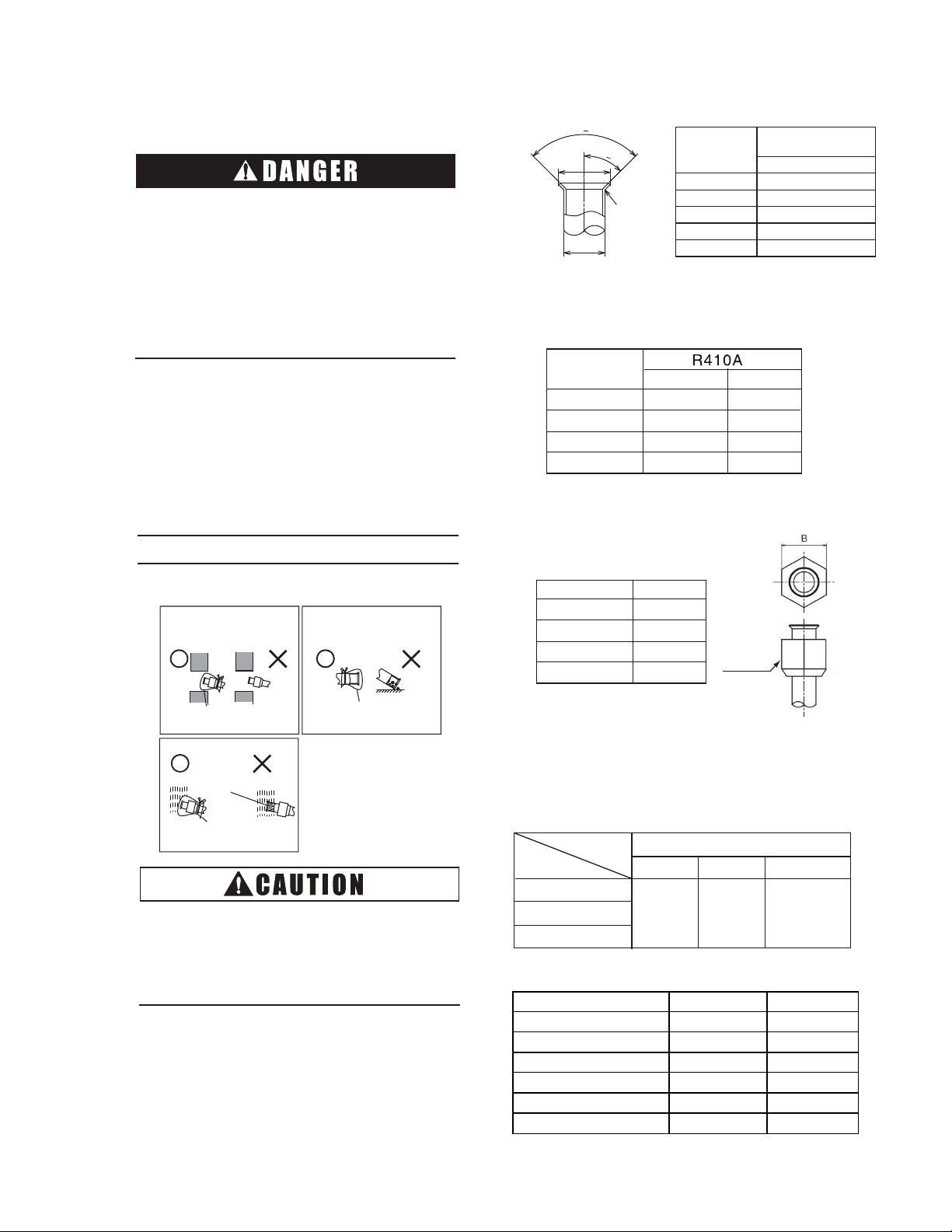
● Flare Nut Dimension
Use the flare nut as below.
<Flare Nut Dimension B in(mm)
Diameter R410A
Flare Nut
8
Use refrigerant R410A in the refrigerant cycle.
Do not charge oxygen, acetylene or other
flammable and poisonous gases into the
refrigerant cycle when performing a leakage
test or an air-tightness test. These types of
gases are extremely dangerous and can
cause an explosion. It is recommended that
compressed air, nitrogen or refrigerant be
used for these types of tests.
5.1 Piping Materials
(1) Prepare locally-supplied copper pipes.
(2) Select the piping size from the Table 5.1.
(3) Select clean copper pipes. Make sure
there is no dust and moisture inside of the
pipes. Blow the inside of the pipes with
nitrogen or dry air, to remove any dust or
foreign materials before connecting pipes.
NOTE
● Cautions for Refrigerant Pipe Ends
When installing pipe through
the wall, secure a cap at the
end of the pipe.
Correct
CorrectIncorrect Incorrect
Correct Incorrect
HoleHole
Attach a cap
or vinyl tape.
Attach a cap
or vinyl tape.
Attach a cap
or vinyl bag with
rubber band.
Do not place the pipe
directly on the ground.
Rain water can
enter.
5. Refrigerant Piping Work
O
O
O
O
● Flaring Dimension
Perform the flaring work as shown below.
● Cap the end of the pipe when the pipe is to
be inserted through a hole.
● Do not put pipes on the ground directly
without a cap or vinyl tape at the end of the
pipe.
work according to the tables.
Table 5.2 Limitation of Outdoor Unit
Outer Diameter of Pipe
Gas Liquid
5.2 Refrigerant Piping Work
(1) Ensure that the directions for refrigerant piping
Diameter
Branch Pipe
B-102H
Capacity
(Btu/h)
36
48
60
Table 5.3 Indoor Unit Pipe Model
Table 5.1 Piping Size
in (mm)
Diameter
(d)
A
+0
-0.02 (-0.4)
R410A
1/4 (6.35) 0.36 (9.1)
3/8 (9.52) 0.52 (13.2)
1/2 (12.7) 0.65 (16.6)
5/8 (15.88) 0.78 (19.7)
3/4 (19.05) (
)
1/64 ~ 1/32R
A
d
90
o
+
2
o
45
o
+
2
o
in (mm)
1/4 (6.35)
3/8 (9.52)
1/2 (12.7)
5/8 (15.88)
0.031 (0.8)
0.031 (0.8)
0.039 (1.0)
0.031 (0.8)
1/4 (6.35)
21/32 (17)
3/8 (9.53)
7/8 (22)
1/2 (12.7)
1-1/32 (26)
5/8 (15.88)
1-5/32 (29)
5/8 (15.88)
3/8 (9.53)
in (mm)
in (mm)
Capacity(kBtu/h) Gas Pipe Liquid Pipe
0~17 1/2(12.7) 1/4(6.35)
19~22(4-Way Cassette) 1/2(12.7) 1/4(6.35)
19(Ducted) 5/8(15.88) 1/4(6.35)
22(Ducted) 5/8(15.88) 3/8(9.53)
18~22(Wall-Mounted) 5/8(15.88) 3/8(9.53)
24~ 5/8(15.88) 3/8(9.53)
Loading ...
Loading ...
Loading ...