
SNAP
EMBOÎTER
AJUSTE A PRESIÓN
LEARN BUTTON
BOUTON APPRENDRE
BOTÓN DE APRENDIZAJE
TONE BUTTON
BOUTON TONALITÉ
BOTÓN DE TONO
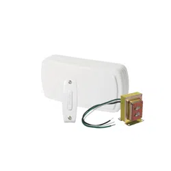
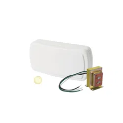
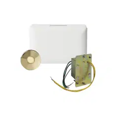
LINE VOLTAGE DOOR CHIME
NuTone offers a chime mechanism that can be wired directly to 120V AC
line voltage inside a two-gang dual voltage junction box (CARLON Model#
SC200DV or equivalent box, minimum 3-in. deep, 20 cu. in. - sold separately).
Use the appropriate wiring directions that follow.
WIRING
Turn Off Power at Service Entrance Before Wiring this Chime.
ALL ELECTRICAL WORK MUST BE DONE IN ACCORDANCE WITH
LOCAL AND/OR NATIONAL ELECTRICAL CODE AS APPLICABLE.
Purpose of Control: Operating Control, Type 1 Action, Pollution
Degree 2, Impulse Voltage: 2500.
Construction of Control: Enclosed plastic, installed in a two-gang dual
voltage junction box.
FINAL WIRING
1. Install a two-gang dual voltage junction box (CARLON Model#
SC200DV or equivalent box, minimum 3-in. deep, 20 cu. in. - sold
separately) at desired location of door chime. Ensure junction box is
positioned properly to mount flush with the drywall.
2. Run 120 VAC to the line voltage side of the junction box.
3. For wired pushbuttons only: Run two conductor 18-22 gauge wire to
chime location. Note: Pushbutton wires MUST NOT be placed inside
the line voltage side of the junction box. Place low voltage wires
through the low voltage opening in the other side of two-gang dual
voltage junction box.
READ AND SAVE THESE INSTRUCTIONS
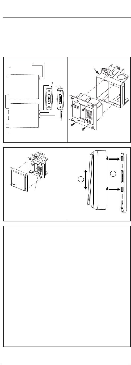
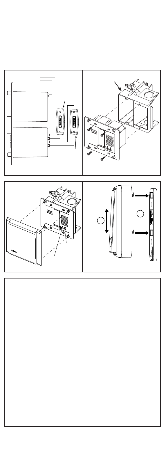
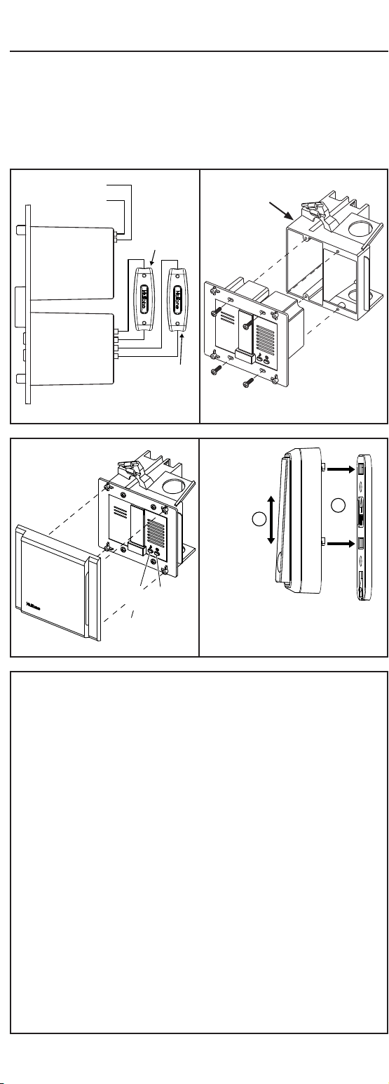
FIG. 2
1. Wire chime mechanism to 120 VAC line (black to black; white to
white). FIG 1
2. If wireless kinetic pushbutton is used, skip to step 5.
3. Press low voltage wires from front door pushbutton into the low
voltage terminal block locations F, and COM1
4. If rear door pushbutton is used press low voltage wires from rear
door pushbutton into the low voltage terminal block locations R,
and COM2.
5. Secure chime mechanism to two-gang dual voltage junction box
with provided four (4) #6-32 screws. FIG. 2
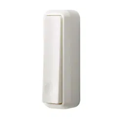
6. Install decorative cover by snapping it onto four posts on the
chime mechanism until it sits flush against the wall FIG. 3.
NOTE: Chime tone selectivity is not an option for wired
configuration. Wired default tones: front - "ding dong", rear - "ding".
For Warranty Statement, Service Parts, Technical Support, or to
Register your product, please visit our website or call:
In the United States - NuTone.com 888-336-6151.
In Canada - NuTone.ca 877-896-1119
ROUGH-IN WIRING
WIRELESS PUSHBUTTON OPERATION
If kinetic button is used, the chime mechanism has two buttons
underneath the decorative cover used for wireless button pairing, and
tone selection.
To pair wireless kinetic buttons:
1. Remove the decorative cover on the chime mechanism
2. Press the LEARN button on the chime mechanism. The LED will be
ON , and the chime will sound BEEP BEEP. FIG 3
3. Press the kinetic button to pair.
4. There are 8 chime tones programmed on the unit. Press the TONE
button to hear each tone, the last played tone will be stored in
memory for the kinetic button. FIG 3
5. If a rear door kinetic button is also used, repeat steps 3 and 4.
Different tones may be selected for front and rear doors.
6. Press the LEARN button again to quit the LEARN mode, LED will
turn off.
7. Install the decorative cover back onto the chime mechanism. FIG 3
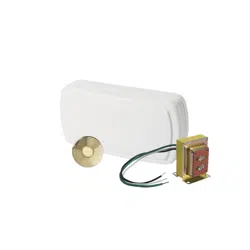
KINETIC BUTTON INSTALLATION
1.
To release the mounting plate push down tab on bottom of pushbutton while
pushing upwards on the body of the button. FIG. 4
2. Place mounting plate in the desired location near the door and secure
using provided two screws.
3. Align the two tabs on the back of the pushbutton with the slots in
mounting plate, and press down until it snaps in place.
120 VAC LINE IN
NEUTRAL
N
L
COM 2
R
COM 1
F
CHIME
MECHANISM
REAR
DOOR
(if included)
FRONT
DOOR
FIG. 1
FIG. 4
Regulatory Information
The 99528969 Chime Mechanism, and PB340K Kinetic Pushbutton are certified to comply with
applicable FCC and IC rules and regulations governing RF and EMI emissions. Refer to 99528969,
and PB340K. This device complies with Part 15 of the FCC Rules. Operation is subject to the
following two conditions: (1) This device may not cause harmful interference, and (2) This device
must accept any interference received, including interference that may cause undesired operation.
FCC Notice
This equipment has been tested and found to comply with the limits for a Class B digital
device, pursuant to Part 15 of the FCC Rules. These limits are designed to provide reasonable
protection against harmful interference in a residential installation. This equipment generates,
uses, and can radiate radio frequency energy and, if not installed and used in accordance with
the instructions may cause harmful interference to radio communications. However, there is no
guarantee that interference will not occur in a particular installation. If this equipment does cause
harmful interference to radio or television reception, which can be determined by turning the
equipment off and on, the user is encouraged to try to correct the interference by one or more of
the following measures:
• Reorient or relocate the receiving antenna.
• Increase the separation between the equipment and receiver
• Connect the equipment into an outlet on a circuit different from that to which the receiver is
connected.
• Consult the dealer or an experienced radio/TV technician to help.
Changes or modifications not expressly approved by the party responsible for compliance could
void the user’s authority to operate the equipment.
ISED Compliance Statement
This device contains licence-exempt transmitter(s)/receiver(s) that comply with Innovation,
Science and Economic Development Canada’s licence-exempt RSS(s). Operation is subject to
the following two conditions:
1. This device may not cause interference.
2. This device must accept any interference, including interference that may cause undesired
operation of the device.
Regulatory ID for PB340K Kinetic Pushbutton
FCC ID: LQP-WB028
IC: 2245A-WB028
1
2
KINETIC
BUTTON
99046096B
CARLON Model#
SC200DV or equivalent
box (sold
separately)
LINE
VOLTAGE
LOW
VOLTAGE
FIG. 3
SNAP
EMBOÎTER
AJUSTE A PRESIÓN
LEARN BUTTON
BOUTON APPRENDRE
BOTÓN DE APRENDIZAJE
TONE BUTTON
BOUTON TONALITÉ
BOTÓN DE TONO
LINE VOLTAGE DOOR CHIME
NuTone offers a chime mechanism that can be wired directly to 120V AC
line voltage inside a two-gang dual voltage junction box (CARLON Model#
SC200DV or equivalent box, minimum 3-in. deep, 20 cu. in. - sold separately).
Use the appropriate wiring directions that follow.
WIRING
Turn Off Power at Service Entrance Before Wiring this Chime.
ALL ELECTRICAL WORK MUST BE DONE IN ACCORDANCE WITH
LOCAL AND/OR NATIONAL ELECTRICAL CODE AS APPLICABLE.
Purpose of Control: Operating Control, Type 1 Action, Pollution
Degree 2, Impulse Voltage: 2500.
Construction of Control: Enclosed plastic, installed in a two-gang dual
voltage junction box.
FINAL WIRING
1. Install a two-gang dual voltage junction box (CARLON Model#
SC200DV or equivalent box, minimum 3-in. deep, 20 cu. in. - sold
separately) at desired location of door chime. Ensure junction box is
positioned properly to mount flush with the drywall.
2. Run 120 VAC to the line voltage side of the junction box.
3. For wired pushbuttons only: Run two conductor 18-22 gauge wire to
chime location. Note: Pushbutton wires MUST NOT be placed inside
the line voltage side of the junction box. Place low voltage wires
through the low voltage opening in the other side of two-gang dual
voltage junction box.
READ AND SAVE THESE INSTRUCTIONS
FIG. 2
1. Wire chime mechanism to 120 VAC line (black to black; white to
white). FIG 1
2. If wireless kinetic pushbutton is used, skip to step 5.
3. Press low voltage wires from front door pushbutton into the low
voltage terminal block locations F, and COM1
4. If rear door pushbutton is used press low voltage wires from rear
door pushbutton into the low voltage terminal block locations R,
and COM2.
5. Secure chime mechanism to two-gang dual voltage junction box
with provided four (4) #6-32 screws. FIG. 2
6. Install decorative cover by snapping it onto four posts on the
chime mechanism until it sits flush against the wall FIG. 3.
NOTE: Chime tone selectivity is not an option for wired
configuration. Wired default tones: front - "ding dong", rear - "ding".
For Warranty Statement, Service Parts, Technical Support, or to
Register your product, please visit our website or call:
In the United States - NuTone.com 888-336-6151.
In Canada - NuTone.ca 877-896-1119
ROUGH-IN WIRING
WIRELESS PUSHBUTTON OPERATION
If kinetic button is used, the chime mechanism has two buttons
underneath the decorative cover used for wireless button pairing, and
tone selection.
To pair wireless kinetic buttons:
1. Remove the decorative cover on the chime mechanism
2. Press the LEARN button on the chime mechanism. The LED will be
ON , and the chime will sound BEEP BEEP. FIG 3
3. Press the kinetic button to pair.
4. There are 8 chime tones programmed on the unit. Press the TONE
button to hear each tone, the last played tone will be stored in
memory for the kinetic button. FIG 3
5. If a rear door kinetic button is also used, repeat steps 3 and 4.
Different tones may be selected for front and rear doors.
6. Press the LEARN button again to quit the LEARN mode, LED will
turn off.
7. Install the decorative cover back onto the chime mechanism. FIG 3
KINETIC BUTTON INSTALLATION
1.
To release the mounting plate push down tab on bottom of pushbutton while
pushing upwards on the body of the button. FIG. 4
2. Place mounting plate in the desired location near the door and secure
using provided two screws.
3. Align the two tabs on the back of the pushbutton with the slots in
mounting plate, and press down until it snaps in place.
120 VAC LINE IN
NEUTRAL
N
L
COM 2
R
COM 1
F
CHIME
MECHANISM
REAR
DOOR
(if included)
FRONT
DOOR
FIG. 1
FIG. 4
Regulatory Information
The 99528969 Chime Mechanism, and PB340K Kinetic Pushbutton are certified to comply with
applicable FCC and IC rules and regulations governing RF and EMI emissions. Refer to 99528969,
and PB340K. This device complies with Part 15 of the FCC Rules. Operation is subject to the
following two conditions: (1) This device may not cause harmful interference, and (2) This device
must accept any interference received, including interference that may cause undesired operation.
FCC Notice
This equipment has been tested and found to comply with the limits for a Class B digital
device, pursuant to Part 15 of the FCC Rules. These limits are designed to provide reasonable
protection against harmful interference in a residential installation. This equipment generates,
uses, and can radiate radio frequency energy and, if not installed and used in accordance with
the instructions may cause harmful interference to radio communications. However, there is no
guarantee that interference will not occur in a particular installation. If this equipment does cause
harmful interference to radio or television reception, which can be determined by turning the
equipment off and on, the user is encouraged to try to correct the interference by one or more of
the following measures:
• Reorient or relocate the receiving antenna.
• Increase the separation between the equipment and receiver
• Connect the equipment into an outlet on a circuit different from that to which the receiver is
connected.
• Consult the dealer or an experienced radio/TV technician to help.
Changes or modifications not expressly approved by the party responsible for compliance could
void the user’s authority to operate the equipment.
ISED Compliance Statement
This device contains licence-exempt transmitter(s)/receiver(s) that comply with Innovation,
Science and Economic Development Canada’s licence-exempt RSS(s). Operation is subject to
the following two conditions:
1. This device may not cause interference.
2. This device must accept any interference, including interference that may cause undesired
operation of the device.
Regulatory ID for PB340K Kinetic Pushbutton
FCC ID: LQP-WB028
IC: 2245A-WB028
1
2
KINETIC
BUTTON
99046096B
CARLON Model#
SC200DV or equivalent
box (sold
separately)
LINE
VOLTAGE
LOW
VOLTAGE
FIG. 3
CARILLON DE PORTE à tension secteur
NuTone offre un mécanisme de carillon qui peut être raccordé directement
à une tension secteur de 120 V CA à l’intérieur d’une boîte de jonction
double CARLON modèle n ° SC200DV ou boîte équivalente, 3 po. profond,
20 cu. po. minimum - (vendu séparément).
Utilisez les directives de câblage qui conviennent ci-dessous.
CÂBLAGE
Coupez le courant au panneau électrique avant de connecter ce carillon.
TOUTES LES CONNEXIONS ÉLECTRIQUES DOIVENT ÊTRE CONFORMES
AU CODE MUNICIPAL ET/OU NATIONAL DE L’ÉLECTRICITÉ EN VIGUEUR.
But de la commande : Commande de fonctionnement, action de type 1,
degré de pollution 2, tension de choc : 2500.
Construction de la commande : Boîtier en plastique, installé dans une
boîte de jonction double.
CÂBLAGE FINAL
1. Installez une boîte de jonction double CARLON modèle n ° SC200DV ou
boîte équivalente, 3 po. profond, 20 cu. po. minimum - (vendu séparément)
à l’endroit voulu pour le carillon. Assurez-vous que la boîte de jonction sera
placée au ras de la surface du mur.
2. Enfilez le câble d’alimentation 120 VCA dans la partie sous tension de la
boîte de jonction.
3. Pour les boutons-poussoirs câblés uniquement : Acheminez un fil à deux
conducteurs de calibre 18-22 jusqu’à l’emplacement du carillon. Remarque
: Lers fils du bouton-poussoir.
NE DOIVENT PAS être placés à l’intérieur du côté sous tension de la boîte
de jonction. Enfilez les fils de basse tension dans l’ouverture du côté basse
tension de la boîte de jonction double.
LISEZ CES DIRECTIVES ET CONSERVEZ-LES
FIG. 2
1. Raccordez le carillon à l’alimentation 120 VCA (noir à noir, blanc à blanc).
FIG. 1
2. Si vous utilisez le bouton-poussoir cinétique, passez à l’étape 5.
3. Pressez les fils de basse tension du bouton-poussoir de la porte avant dans
les bornes de basse tension F et COM1.
4. Si vous utiisez un bouton-poussoir pour la porte arrière, pressez les fils de
basse tension du bouton-poussoir de la porte arrière dans les bornes de
basse tension R et COM2.
5. Fixez le mécanisme du carillon sur la boîte de jonction double avec les
quatre (4) vis n° 6-32 fournies. FIG. 2
6. Installez le couvercle décoratif en l’emboîtant dans les quatre goujons du
mécanisme du carillon jusqu’à ce qu’il soit au ras du mur FIG. 3
REMARQUE : Le choix de la tonalité du carillon n’est pas possible en
configuration câblée. Tonalités par défaut câblées: avant - "ding dong",
arrière - "ding".
Pour la déclaration de garantie, les pièces de rechange, l’assistance
technique ou pour enregistrer votre produit, veuillez visiter notre site
Web ou appeler : Aux États-Unis : NuTone.com 888-336-6151
Au Canada : NuTone.ca 877-896-1119
CÂBLAGE BRUT
FONCTIONNEMENT DU BOUTON-
POUSSOIR SANS FIL
Si vous utilisez le bouton cinétique, le carillon comporte deux boutons sous le
couvercle décoratif servant à jumeler les boutons sans fil et sélectionner la tonalité.
Pour jumeler les boutons cinétiques sans fil :
1. Enlevez le couvercle décoratif du mécanisme du carillon.
2. Appuyez sur le bouton LEARN (Apprendre) du mécanisme du carillon. La DEL
s’allume, et le carillon fait BIP BIP. FIG. 3
3. Appuyez sur le bouton cinétique pour le jumeler.
4. Huit tonalités de carillon sont programmées. Appuyez sur le bouton TONE
(Tonalité) pour entendre chaque son, la dernière tonalité écoutée étant alors
mise en mémoire pour le bouton cinétique. FIG. 3
5. Si vous utilisez aussi un bouton cinétique pour la porte arrière, répétez les
étapes 3 et 4. Différents tons peuvent être sélectionnés pour les portes avant
et arrière.
6. Appuyez de nouveau sur le bouton LEARN (Apprendre) pour quitter le mode
d’apprentissage et la DEL s’éteindra.
7. Remettez le couvercle décoratif sur le mécanisme du carillon. FIG. 3
INSTALLATION D’UN BOUTON
CINÉTIQUE
1. Pour dégager la plaque de montage, appuyez sur l’onglet situé au bas du
bouton-poussoir tout en poussant le corps du bouton vers le haut. FIG. 4
2. Placez la plaque de montage à l’endroit voulu près de la porte et fixez-la avec
les deux vis fournies.
3. Alignez les deux onglets à l’endos du bouton-poussoir sur les fentes de la
plaque de montage et pressez pour engager le bouton en place.
ENTRÉE 120 VCA
NEUTRE
N
L
COM 2
R
COM 1
F
MÉCANISME
DE CARILLON
PORTE
ARRIÈRE
(si incluse)
PORTE
AVANT
FIG. 1
FIG. 4
FIG. 3
Avis relatif à la réglementation
Le mécanisme de carillon 99528969 et le bouton-poussoir cinétique PB340K sont certifiés conformes
à la réglementation de la FCC et d’Industrie Canada régissant les émissions FR et les interférences
électromagnétiques. Se reporter à 99528969 et PB340K. Cet appareil est conforme aux normes énoncées
à la section 15 des règlements de la FCC. Son fonctionnement est assujetti aux deux conditions suivantes :
(1) l’appareil ne doit pas provoquer d’interférences nuisibles, et (2) il doit tolérer les interférences reçues,
notamment celles susceptibles de provoquer un fonctionnement non souhaité.
AVIS DE LA FCC
Cet équipement a été testé et constaté conforme aux limites des appareils numériques de Classe B
en vertu de la section 15 des Règlements de la FCC. Ces limites visent à offrir une protection raisonnable
contre les interférences indésirables dans une installation résidentielle. Cet équipement génère, utilise et
peut émettre des radiofréquences et, s’il n’est pas installé et utilisé conformément aux instructions, peut
produire des interférences nuisibles pour les radiocommunications. Il n’y a toutefois aucune garantie que
des interférences ne se produiront pas dans une installation particulière. Si cet équipement produit des
interférences qui nuisent à une réception radio ou télévisuelle, ce qui peut être déterminé en éteignant et
en allumant l’appareil, l’utilisateur est invité à corriger la situation par l’un ou l’autre des moyens suivants :
• Réorienter ou déplacer l’antenne réceptrice.
• Éloigner l’équipement du récepteur.
• Brancher l’équipement dans une autre prise de courant sur un circuit différent de celui du récepteur.
• Consulter le détaillant ou un technicien spécialisé en radio / télévision.
Toute modification non expressément approuvée par la partie responsable du respect de la réglementation
peut annuler le droit de l’utilisateur d’utiliser cet équipement.
Déclaration de conformité ISED
L’émetteur/récepteur exempt de licence contenu dans le présent appareil est conforme aux CNR
d’Innovation, Sciences et Développement économique Canada applicables aux appareils radio exempts
de licence. L’exploitation est autorisée aux deux conditions suivantes :
1. L’appareil ne doit pas produire de brouillage;
2. L’appareil doit accepter tout brouillage radioélectrique subi, même si le brouillage est susceptible d’en
compromettre le fonctionnement.
Identiant réglementaire du bouton-poussoir cinétique PB340K
Identifiant de la FCC : LQP-WB028
Identifiant d’Industrie Canada : 2245A-WB028
EMBOÎTER
BOUTON
APPRENDRE
BOUTON
TONALITÉ
BOUTON
CINÉTIQUE
99046096B
CARLON MODÈLE N° SC200DV OU
BOÎTE ÉQUIVALENTE
(VENDU
SÉPARÉMENT)
TENSION DU
SECTEUR
BASSE
TENSION
1
2
TIMBRE DE PUERTA de voltaje de línea
NuTone ofrece un mecanismo de timbre que se puede cablear directamente al voltaje
de línea de 120 VCA dentro de una caja doble de conexiones de voltaje de dos tomas
CARLON Modelo # SC200DV o caja equivalente, 3 pulg. profundo, 20 pies cúbicos
pulg. mínima - (se vende por separado).
Siga correctamente las siguientes instrucciones de cableado.
CABLEADO
Desconecte la alimentación en la acometida eléctrica antes de conectar
los cables del timbre.
TODO EL TRABAJO ELÉCTRICO DEBE REALIZARSE DE ACUERDO CON LOS
CÓDIGOS ELÉCTRICOS LOCALES Y/O NACIONALES CORRESPONDIENTES.
Propósito del control: Control de funcionamiento, acción tipo 1,
contaminación grado 2, voltaje de impulso: 2500.
Construcción del control: Plástico cerrado, instalado en una caja de
conexiones de voltaje doble de dos tomas.
CABLEADO FINAL
1. Instale una caja doble de conexiones de voltaje de dos tomas CARLON
Modelo # SC200DV o caja equivalente, 3 pulg. profundo, 20 pies cúbicos
pulg. mínima - (se vende por separado) en la ubicación deseada del
timbre de la puerta. Asegúrese de que la caja de conexiones esté situada
adecuadamente para que se monte a nivel con la pared de yeso.
2. Conecte los 120 VCA en el lado del voltaje de línea de la caja de conexiones.
3. Pase un alambre calibre 18-22 de dos conductores a la ubicación del
timbre. Nota: Los alambres del botón NO deben colocarse dentro del
lado del voltaje de línea de la caja de conexiones. Coloque alambres de
bajo voltaje a través de la abertura de bajo voltaje en el otro lado de la
caja doble de conexiones de voltaje de dos tomas.
LEA Y CONSERVE ESTAS INSTRUCCIONES
FIG. 2
1. Cablee el mecanismo del timbre a la línea de 120 VCA (negro con negro,
blanco con blanco). FIG. 1
2. Si usa el botón cinético inalámbrico, continúe con el paso 5.
3. Presione los alambres de bajo voltaje del botón de la puerta delantera en
el bloque de terminales de bajo voltaje, en las ubicaciones F y COM1.
4. Si usa un botón para la puerta trasera, presione los alambres de bajo
voltaje del botón de la puerta trasera en el bloque de terminales de bajo
voltaje, en las ubicaciones R y COM2.
5. Asegure el mecanismo del timbre a la caja doble de conexiones de voltaje
de dos tomas con los cuatro (4) tornillos #6-32 suministrados. FIG. 2
6. Instale la cubierta decorativa a presión sobre los cuatro postes del
mecanismo del timbre hasta que quede a nivel contra la pared. FIG. 3
NOTA: La capacidad de seleccionar el tono del timbre no es opción para
la configuración cableada.
Si desea consultar la declaración de garantía, repuestos de servicio, apoyo
técnico o para registrar su producto, visite nuestro sitio web o llame:
En Estados Unidos: - NuTone.com 888-336-6151
En Canadá - NuTone.ca 877-896-1119
CABLEADO HASTA EL EMPALME
OPERACIÓN DEL BOTÓN INALÁMBRICO
Si usa el botón cinético, el mecanismo del timbre tiene dos botones por debajo
de la cubierta decorativa, que se usan para acoplar el botón inalámbrico y para la
selección del tono.
Para acoplar botones cinéticos inalámbricos:
1. Retire la cubierta decorativa en el mecanismo del timbre.
2. Presione el botón LEARN (Aprender) en el mecanismo del timbre. La luz LED
se encenderá y el timbre emitirá dos pitidos BIP BIP. FIG. 3
3. Presione el botón cinético para acoplar.
4. La unidad tiene 8 tonos de timbre programados. Presione el botón TONE
(Tono) para escuchar cada tono; el último tono reproducido se guardará en
la memoria para el botón cinético. FIG. 3
5. Si también usa el botón cinético de la puerta trasera, repita los pasos 3 y
4. Se pueden seleccionar diferentes tonos para las puertas delanteras y
traseras.
6. Presione otra vez el botón LEARN (Aprender) para salir del modo de
aprendizaje y la luz LED se apagará.
7. Instale la cubierta decorativa nuevamente en el mecanismo del timbre. FIG. 3
INSTALACIÓN DEL BOTÓN CINÉTICO
1.
Para liberar la placa de montaje, presione hacia abajo la pestaña en la parte
inferior del botón mientras empuja hacia arriba el cuerpo del botón. FIG. 4
2. Coloque la placa de montaje en la ubicación deseada cerca de la puerta y asegure
con los dos tornillos suministrados.
3. Alinee las dos pestañas en la parte posterior del botón con las ranuras en la
placa de montaje y presione hacia abajo hasta que se sujete en su lugar con un
chasquido.
LÍNEA DE ENTRADA
DE 120 VCA
NEUTRO
N
L
COM 2
R
COM 1
F
MECANISMO
DEL TIMBRE
PUERTA
TRASERA
(si se incluye)
PUERTA
DELANTERA
FIG. 1
FIG. 4
FIG. 3
Información normativa
El mecanismo de timbre 99528969 y el botón cinético PB340K están certificados para cumplir con
las reglas y reglamentos de FCC e IC correspondientes que rigen las emisiones de RF y EMI. Consulte
99528969 y PB340K. Este dispositivo cumple con la Parte 15 de las reglas de la FCC. La operación está
sujeta a las dos condiciones siguientes: (1) Este dispositivo no puede ocasionar interferencias nocivas,
y (2) Este dispositivo debe aceptar cualquier interferencia recibida, incluida la interferencia que pueda
provocar un funcionamiento no deseado.
Aviso de la FCC
Este equipo ha sido probado y se determinó que cumple con los límites de un dispositivo digital Clase
B, de conformidad con la parte 15 de las Reglas de la FCC. Estos límites están diseñados para brindar
una protección razonable contra las interferencias nocivas en una instalación residencial. Este equipo
genera, utiliza y puede irradiar energía de radiofrecuencia y, si no se instala y utiliza de acuerdo con
las instrucciones, podría causar interferencias nocivas a las comunicaciones por radio. No obstante,
no hay garantía de que no se generará interferencia en una instalación particular. Si el equipo provoca
interferencias nocivas en la recepción de señales de radio o de televisión, lo cual se puede determinar
apagando y encendiendo el equipo, se recomienda al usuario que trate de corregir la interferencia
mediante una o más de las siguientes medidas:
• Reorientar o reubicar la antena de recepción.
• Aumentar la separación entre el equipo y el receptor.
• Conectar el equipo en un tomacorriente en un circuito diferente a aquel donde esté conectado el receptor.
• Solicite asistencia al distribuidor o a un técnico con experiencia en radio y TV.
Los cambios o modificaciones no aprobados expresamente por la parte responsable del cumplimiento
podrían anular la autoridad del usuario para operar el equipo.
Declaración de cumplimiento ISED
Este dispositivo contiene transmisor(es) / receptor(es) exento(s) de licencia que cumplen con los RSS(s)
exentos de licencia de Innovación, Ciencia y Desarrollo Económico de Canadá. La operación está sujeta a
las siguientes dos condiciones:
1. Este dispositivo no puede causar interferencias.
2. Este dispositivo debe aceptar cualquier interferencia, incluida la interferencia que pueda causar un
funcionamiento no deseado del dispositivo.
ID regulatoria para el botón cinético PB340K
ID de la FCC: LQP-WB028
ID de la IC: 2245A-WB028
AJUSTE
A PRESIÓN
BOTÓN
DE TONO
BOTÓN DE
APRENDIZAJE
1
2
BOTÓN
CINÉTICO
99046096B
CARLON Modelo # SC200DV o
caja equivalente
(se vende por
separado)
VOLTAJE
DE LÍNEA
BAJO
VOLTAJE

99046096B

99046096B