Loading ...
Loading ...
Loading ...
9
English
Attaching and Removing Polishing Pads
(Fig.C, D)
WARNING: To reduce the risk of serious personal
injury, do not allow any loose portion of the polishing
bonnet or its attachment strings to spin freely. Tuck
away or trim any loose attachment strings. Loose and
spinning attachment strings can entangle your fingers
or snag on theworkpiece.
Polishing pads with a diameter of 7" (180 mm) may be used
with the DCM849.
nOTE: The DCM849 may use either type of polishing pad
assembly describedbelow.
To Attach Polishing Pad with Rubber
Backing Pad (Fig. A, C)
1. To attach polishing pad
14
, push the hub of the clamp
washer
15
through the hole in the center of the
polishing pad as far as it willgo.
Soft Rubber Gear Case Cover (Fig.A)
The soft rubber gear case cover
9
is designed to eliminate
metal gear case scuffs on painted or polishedsurfaces.
The soft rubber gear case cover can be removed if required.
To take off the cover, remove the three mounting screws
and lift the cover over the gearcase.
Your tool may come with a soft rubber gear case cover. The
soft rubber gear case cover is available at extra cost from
your local dealer or authorized servicecenter.
Wool Ingestion Shields (Fig.A)
The wool ingestion shields
10
are designed to reduce the
amount of wool, dust, and debris that gets ingested by the
motor during normal use. The goal of the ingestion shields
is to improve durability as compared to a unit without the
ingestionshields.
Each ingestion shield can be easily removed for cleaning by
slipping a finger or coin underneath the removal recess and
pulling to release thecover.
The wool ingestion shields can be cleaned with soap and
water and a soft bristle brush in the event they get clogged
with polish and debris. Clean the shields as soon as you start
to see buildup on theoutside.
Your tool may come with a set of wool ingestion shields.
The wool ingestion shields are available at extra cost from
your local dealer or authorized servicecenter.
Handles
Attaching Auxiliary Handle (Fig. A)
WARNING: Before using the tool, check that the
handle is tightenedsecurely.
Screw the auxiliary handle
7
tightly into one of the holes
on either side of the gear case. The auxiliary handle should
always be used to maintain control of the tool at alltimes.
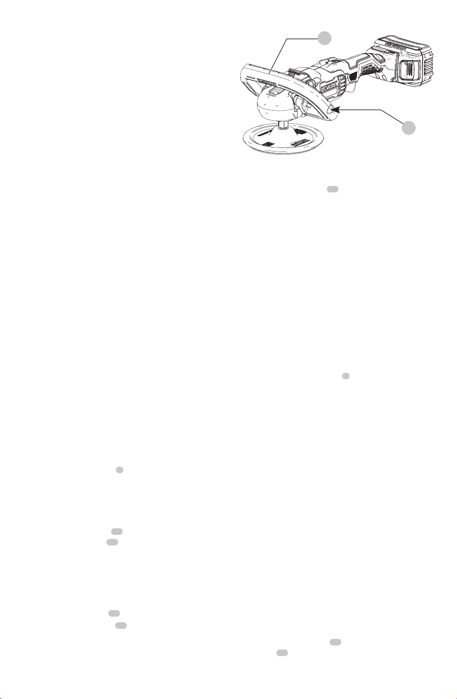
Installation of the Bail Handle Assembly
(Fig B)
1. Place the bail handle
12
over the polisher gear case
aligning the screws
13
with the threaded holes and
the ears on the gear case with the slots in the bail
handleassembly.
2. Tighten the screws with the supplied hex wrench to
secure the handle to thepolisher.
Adjustment of the Bail handle Angle (Fig. B)
1. Loosen both screws
13
2 fullturns.
2. Rotate the bail handle
12
to the desired 45˚ or 90˚
position making sure that the detent grovesalign.
3. Re-tighten the screws to secure the handle to
thepolisher.
ASSEMBLY AND ADJUSTMENTS
WARNING: To reduce the risk of serious personal
injury, turn unit off and remove the battery pack
before making any adjustments or removing/
installing attachments or accessories. An
accidental start-up can causeinjury.
Intended Use
The DCM849 heavy-duty polisher is designed for polishing
painted or unfinished metal, fiberglass, and composite
surfaces in professional applications. Common examples
of use include but are not limited to: auto/marine/RV/
motorcycle detailing and finish correction, boat construction
and repair, and metal or concretefinishing.
DO nOT use under wet conditions or in presence of
flammable liquids orgases.
DO nOT let children come into contact with the tool.
Supervision is required when inexperienced operators use
thistool.
Wall Mounting
DCB107, DCB112, DCB113, DCB115, DCB118, DCB132
These chargers are designed to be wall mountable or to
sit upright on a table or work surface. If wall mounting,
locate the charger within reach of an electrical outlet,
and away from a corner or other obstructions which may
impede air flow. Use the back of the charger as a template
for the location of the mounting screws on the wall. Mount
the charger securely using drywall screws (purchased
separately) at least 1” (25.4 mm) long, with a screw head
diameter of 0.28–0.35” (7–9mm), screwed into wood to an
optimal depth leaving approximately 7/32” (5.5 mm) of the
screw exposed. Align the slots on the back of the charger
with the exposed screws and fully engage them in theslots.
Fig. B
12
13
Loading ...
Loading ...
Loading ...