WARNING! Do not set relative humidity too high during cold
weather. Over humidification can result in condensation,
structural damage and mold. Condensation within a building's
structure can cause loss of structural strength. Condensation
can also enable mold and mildew growth resulting in personal
injury and damage to building structure and contents.
RESIDENTIAL AIR TREATMENT PRODUCTS
Manual humidistat/dehumidistat
control
R
II. APPLICATION
The MHX3 control provides low voltage control of most
humidifiers. The humidistat uses a SPDT switch and is designed
for wall mounting in the living area or mounting on the return air
duct.
RANGE: 10% to 85% RH ELECTRICAL RATING: 30 VAC, 60 VA
OPERATING MODES
The MHX3 can be configured for operation as a standard
humidistat or dehumidistat. When using this product as a
standard humidstat terminals C and NO must be used. Use MHX3
face plate for the humidistat version. When using this product as a
dehumidistat terminals C and NC must be used. Use DHX3 face
plate for the dehumidistat version.
I. SAFETY
WARNING! Improper electrical wiring can result in fire,
failure or loss of humidity control. Disconnect electrical
power before installing and servicing. Failure to disconnect
electrical power may result in injury or death. All local
building and electrical codes must be followed.
The MHX3 humidistat must be installed by a qualified technician.
Failure to properly install the MHX3C may result in property
damage or personal injury.
Homeowners must read instructions and understand the operation
of the MHX3 and the humidifier(s) it controls.
Improper operation can result in over or under humidification.
Over humidification can result in condensation, structural damage
and mold. Condensation within a building's structure can cause
loss of structural strength. Condensation can also enable mold
and mildew growth resulting in personal injury and damage to
building structure and contents.
Safety questions regarding the MHX3 may be directed to General
Filters, Inc. Toll free (866) 476-5101
MHX3
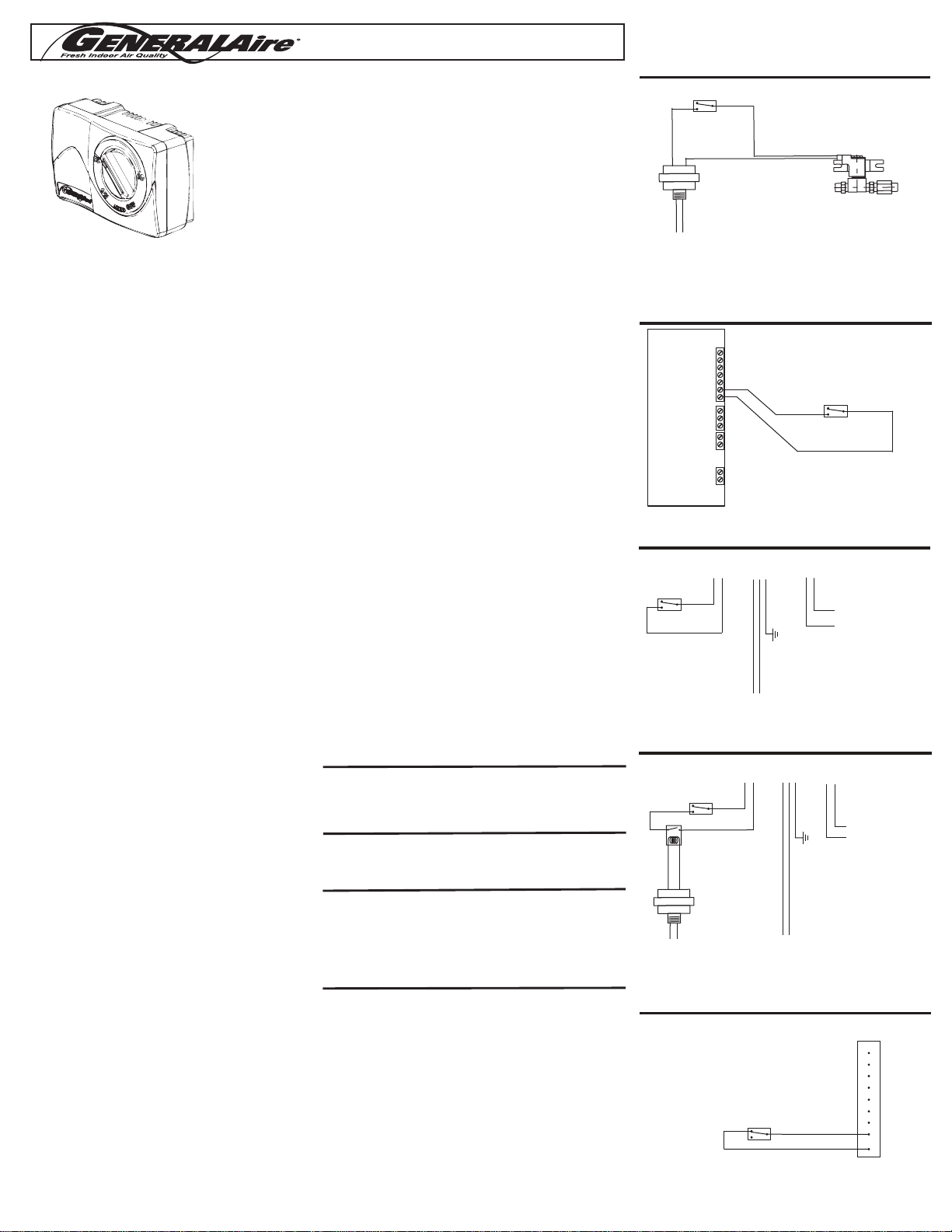
WIRING DIAGRAMS
DIAGRAM 1 WIRING 24V. BYPASS HUMIDIFIER
HUMIDIFIER 24V.
SOLENOID VALVE
OR 24V. DRUM MOTOR
727-58
24 V. TRANSFORMER
(OMIT IF POWER SUPPLY
IS 20-30 VAC)
120V. POWER SUPPLY
SWITCHED WITH FURNACE OPERATION
HMX3
Humidistat
USE TERMINALS C AND NO FOR HUMDISTAT
DIAGRAM 2
WIRING HIGH LIMIT HUMIDISTAT WITH ELITE STEAM HUMIDIFIER
STEAM HUMIDIFIER
CONTROL MODULE
HUMIDISTAT
N2
GND
N1
AB
AB
GND
IN
NO
C
NC
C
NO
GND
24V
DIAGRAM 3 WIRING 120V. 1137/1000 POWER HUMIDIFIER
HUMIDIFIER CONTROL LEADS
(YELLOW WIRES)
HUMIDISTAT
HUMIDIFIER 24V AUX POWER
(RED WIRES)
(NOT USED, ATTACH WIRE
NUTS TO EACH LEAD)
DO NOT TOUCH TOGETHER!
110V SWITCHED WITH FURNACE HEATING CYCLE
L1 N
G
HUMIDIFIER
POWER CORD
DIAGRAM 4
WIRING 120V. 1137/1000 POWER HUMIDIFIER
HUMIDIFIER 24V AUX POWER
(RED WIRES)
(NOT USED, ATTACH WIRE
NUTS TO EACH LEAD)
DO NOT TOUCH TOGETHER!
110V CONSTANT VOLTAGE
HUMIDIFIER CONTROL LEADS
(YELLOW WIRES)
HUMIDISTAT
110V SWITCHED WITH
FURNACE HEATING CYCLE
FIELD SUPPLIED RELAY
24V COIL, N.O. 5A MIN.
L1 N
L1
N
G
HUMIDIFIER
POWER CORD
727-58
24 V. TRANSFORMER
(OMIT IF POWER
SUPPLY IS 20-30 VAC)
TROUBLESHOOTING -- Humidistat Version
SYMPTOM
DIAGNOSTIC STEPS
Humidifier turns
on and off
repeatedly
1. If mounted on wall, verify wire clearance hole in wall is sufficiently
insulated to preven drafts from affecting the humidistat.
2. If mounted on return air duct, verify humidistat is at least 24”
upstream of humidifiers air discharge.
Humidifier
operates
continuously
1. When the humidity in the home is less than the knob setting on
the humidistat the stat will operate the humidfier until the humidity
is higher. Reduce knob setting.
2. Verify function of solenoid valve.
No humidifier
operation in “ON”
mode
1. Set the thermostat to operate both furnace burner and blower.
Operation may be necessary for system power.
2. Verify terminals 2 and 3 are used on the humidistat. These are the
contacts for humidification.
3. Check voltage at at terminals 2 and 3. There should be no voltage
for an Elite Steam or 1137/1000 power humidifier. Voltage should
be 20-30 VAC from most others.
4. Verify humidifier operation by bypassing the humidistat.
Ideal humidity is
not achieved
1. Technical fault with humidifier. Check water supply, electrical
connnections and condition of the evaporator pad. Verify metering
orifice at the solenoid valve is not obstructed.
2. Humidifier run time is too short. Switch water supply to hot water if
appropriate (use copper tubing).
3. Excess air infiltration. Seal sources of air loss.
4. Humidifier is undersized. Switch water supply to hot water if
appropriate (use copper tubing). Add additional unit(s) or
replace existing unit with a larger unit.
USE TERMINALS C AND NO
FOR HUMDISTAT
DIAGRAM 5
1300 DEHUMIDIFIER
HUMIDISTAT
DH
G2
S1
S2
G1
C
W
Y
D
GENERALAIRE 1300
DEHUMIDIFIER
FORM NO MHX3-06 REV C
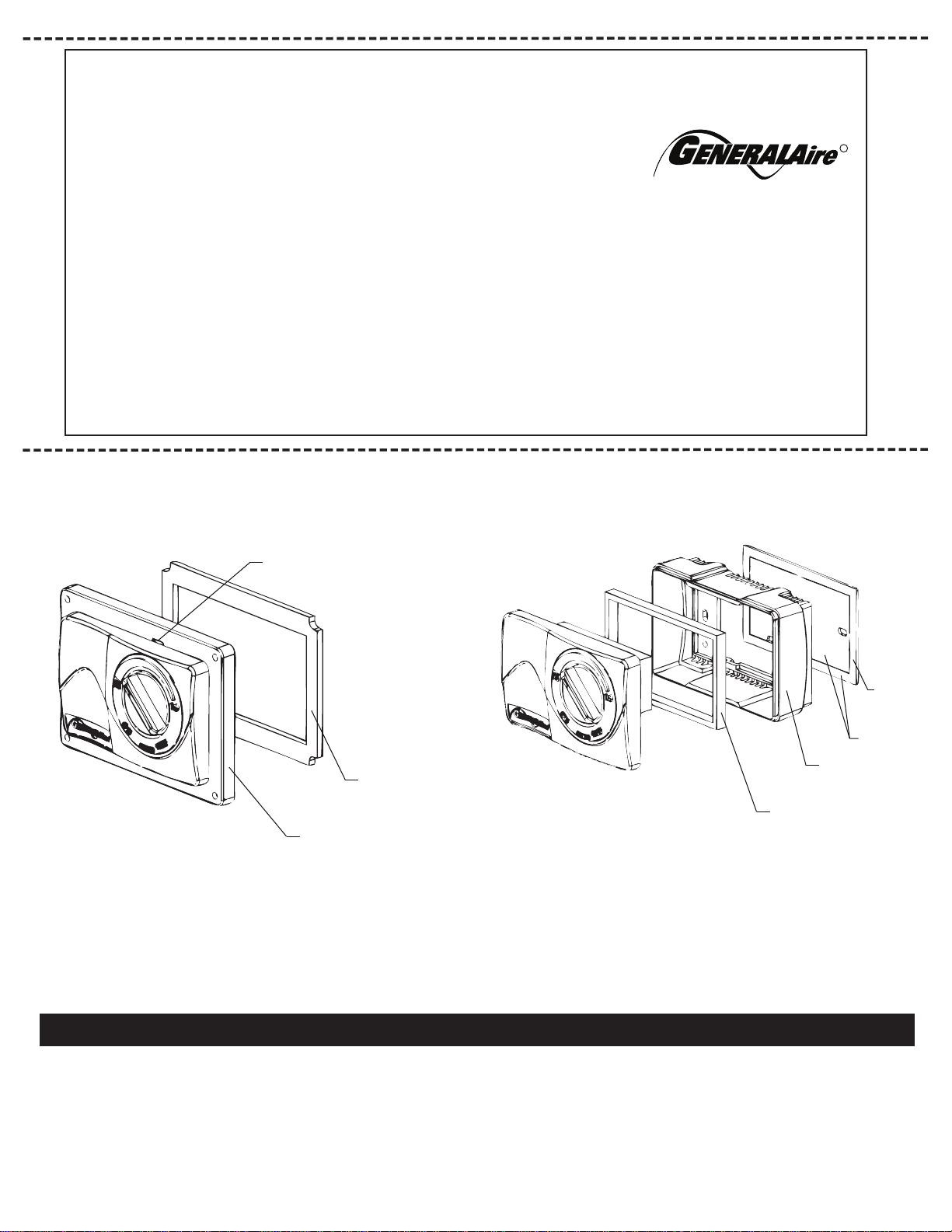
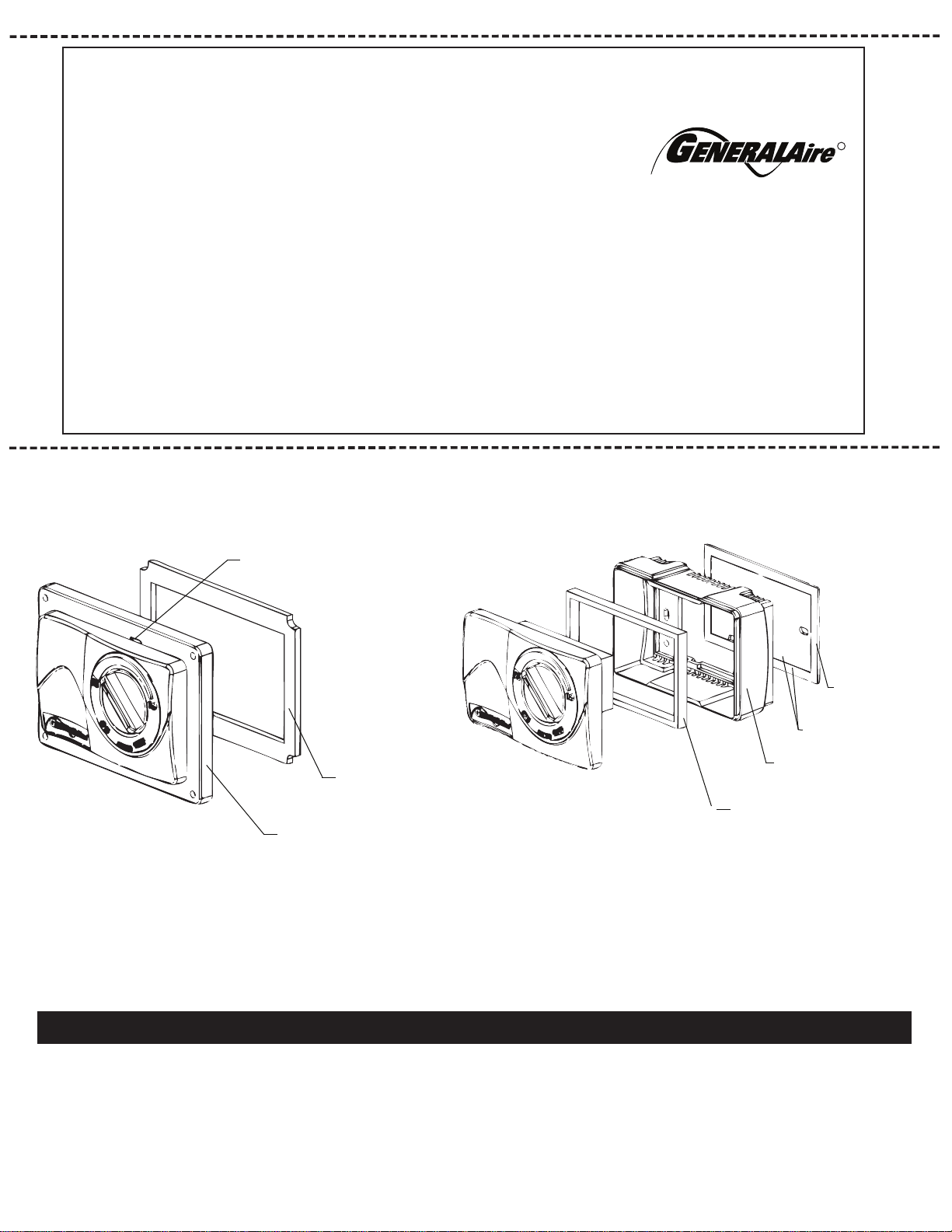
WALL MOUNT VERSION
FIG. 1
USE TERMINALS C AND NO FOR HUMDISTAT
USE TERMINALS C AND NO FOR HUMDISTAT
USE TERMINALS C AND NC FOR DEHUMDISTAT
C
NO
NC
C
NO
NC
C
NO
NC
C
NO
NC
C
NO
NC
III. INSTALLATION INSTRUCTIONS - PRECAUTIONS
The installer must be a qualified technician. Disconnect electrical
power before begining installation. Do not install the humidistat
on the warm air duct. Conduct a thorough checkout before leaving
the installation.
WALL MOUNT INSTRUCTIONS - Humidistat/Dehumidistat
versions
1. Choose a location for the MXH3 about five feet above the floor
on an inside wall with average room temperature and relative
humidity conditions.
2. Drill a small hole in the wall and run low voltage wiring to the
location chosen. Pull about 6” of wire through the hole.
Use the entire mounting gasket (both inside and outside
portions) to seal the wall opening or use foam tape to prevent
drafts from affecting the humidistat operation. (see fig 3.)
3. Remove the knob on the humidistat. Squeeze the top and
bottom of the base to release the face of the humidistat.
4. Mount the base horizontally over the wires. Attach directly to
the wall, using the two screws provided in the slotted holes.
5. Connect the wires to the screw terminals on the control assembly
as shown in wiring DIAGRAMS 1-5 Replace face and Knob.
DUCT MOUNTING ON THE RETURN AIR - WALL BASE
Humidistat/Dehumidistat versions (optional)
Do not install the humidistat on the warm air duct or within 48”
of UV light.
1. Locate the humidistat at least 24” upstream of the humidifier or
bypass on the return air duct. Avoid areas of direct radiation like
secondary heat exchanger in the fan compartment.
2. Cut a square in the duct 2-1/4” wide and 1-3/4” tall. Remove the
inner portion of the mounting gasket and discard. Use the outer
portion to seal between the plastic base and the duct. Line up the
base with the cut out and accurately mark the holes thru the plastic
duct mount
plate. (see fig 3.)
3. Revove the humidistat and drill four 3/32” mounting holes.
4. Place the outer portion of the mounting gaskets on the plastic base
and mount the base with four screws. Low voltage wire may enter
the humidistat under the gasket.
5. Connect wires to screw terminals on the control assembly as
shown in wiring DIAGRAMS 1-5. Replace the face and knob.
DUCT MOUNTING ON THE RETURN AIR - DUCT BASE
Humidistat/Dehumidistat versions (recommended)
Do not install the humidistat on the warm air duct or within 48”
of UV light.
1. Locate the humidistat at least 24” upstream of the humidifier
or bypass on the return air duct. Avoid areas of direct radiation
like secondary heat exchanger in the fan compartment.
2. Remove face by inserting screwdriver into the pry slot and
twisting (see fig. 2)
3. Use the plastic duct mount plate as a template. Accurately mark
and drill the (4) 3/32” mounting holes and cut away the 4-1/4” x 2-1/2”
section of the duct mount plate.
4. Place duct mount base gasket on the humidistat base and mount
the base with four screws. Low voltage wire may enter the humidistat
under the gasket (see fig. 2)
5. Connect wires to screw terminals on the control assembly as shown in
wiring DIAGRAMS 1-5. Replace face and knob.
MHX3 CALIBRATION INSTRUCTIONS
(Accurate humidity gauge required)
1. Use an accurate humidity gauge to determine the current relative
humidity in the room where the humidstat is located. This relative
humidity will be used in step 5.
2. Remove the face plate from the housing.
3. Turn the knob on the MHX3 faceplate to the “on” position
4. Very slowly, turn the knob clockwise until you hear a “click” from
the humidistat control and leave the knob in this position.
5. Turn the ring (not the knob) so that the knob is pointed directly
at the current relative humidity number determined in STEP 1.
6. The humidistat in now calibrated to match you humidity gauge.
Product Information:
Serial Number: _____________________________________________________________
Model: ____________________________________________________________________
Install Date: Month _______________ Day ______________ Year _____________
Owner Information:
Name: _____________________________________________________________________
Address: ___________________________________________________________________
Address 2: __________________________________________________________________
City: _______________________ State: ___________ Zip Code: ____________________
Phone: _____________________________________________________________________
Email: ______________________________________________________________________
WARRANTY REGISTRATION
Contractor Information:
Contractor Name: _____________________________________________________________
Address: ____________________________________________________________________
Address 2: ___________________________________________________________________
City: _____________________ State: ___________ Zip Code: _______________________
Contractor Phone: ____________________________________________________________
Contractor Email: _____________________________________________________________
You may register online at www.GeneralAire.com or mail form below
Mail Form To:
General Filters, Inc
Attn: Warranty Dept.
43800 Grand River Ave.
Novi, MI 48375
Fresh Indoor Air Quality
R
cut along dashed line
cut along dashed line
USA CUSTOMERS
General Filters, Inc.
43800 Grand River Ave.
Novi, MI 48375
www.GeneralAire.com
Toll Free (866) 476-5101
CANADIAN CUSTOMERS
Canadian General Filters, Ltd.
400 Midwest Rd.
Toronto, ON M1P3A9 Canada
www.CGFProducts.com
Tel. (416) 757-3691
TECHNICAL SUPPORT
FORM NO MHX3-06 REV C
USE BOTH WITH
WALL MOUNTING
USE WITH DUCT
MOUNTING ONLY
USE OUTSIDE
PORTION ONLY
WITH DUCT
MOUNTING
GASKET PLACEMENT
FIG. 3
DUCT MOUNT
VERSION
FIG. 2
DUCT MOUNT BASE
MHX3-11
DUCT MOUNT BASE
GASKET
SCREWDRIVER PRY SLOT
WALL MOUNT BASE
(CAN MOUNT ON DUCT
WITH GASKETS SHOWN)
PRODUITS DE TRAITEMENT D’AIR RÉSIDENTIELS
Commande manuelle
de l’humidistat/déshumidistat
R
SYMPTÔME
ÉTAPES DU DIAGNOSTIC
I. SÉCURITÉ
MISE EN GARDE! Un câblage électrique inapproprié risque de
provoquer un incendie, une panne ou une perte de contrôle de
l’humidité. Débrancher l’appareil de sa source d’alimentation
électrique avant de l’installer et d’en faire l’entretien. Le
non-respect de cette consigne peut entraîner des blessures ou la
mort. Tous les codes locaux de construction et d’électricité doivent
être respectés.
L’humidistat MHX3 doit être installé par un technicien qualifié. Une
installation incorrecte du MHX3C peut entraîner des dommages
matériels et des blessures.
Les propriétaires de maison doivent lire et comprendre le
fonctionnement du MHX3 et les commandes du ou des humidificateurs.
Un fonctionnement incorrect peut entraîner une humidité trop élevée ou
trop basse.
Une humidité trop élevée peut causer de la condensation, des
dommages structurels et de la moisissure. La présence de condensation
dans les structures d’un édifice peut provoquer une perte de résistance
structurale. La condensation peut également favoriser la croissance de
moisissure qui peut occasionner des problèmes de santé et
endommager la structure et le contenu de l’édifice.
Les questions de sécurité concernant le MHX3 peuvent être adressées
à General Filters, Inc. en composant le numéro sans frais
866-476-5101.
II. APPLICATIONS
Les commandes du MHX3 permettent de régler la tension de la plupart
des humidificateurs. L’humidistat utilise un interrupteur unipolaire
bidirectionnel conçu pour une installation murale dans un endroit habité
ou sur le conduit de reprise.
PLAGE DE VALEURS : 10 % à 85 % HR
CARACTÉRISTIQUES ÉLECTRIQUES : 30 volts c.a., 60 VA
MODES DE FONCTIONNEMENT
Le MHX3 peut être configuré pour fonctionner comme un humidistat
standard ou un déshumidistat. Lorsque cet appareil est utilisé comme
humidistat standard, les bornes (C) et (NO) doivent être utilisées.
Utiliser la plaque frontale MHX3 pour le humidistat. Lorsque cet appareil
est utilisé comme déshumidistat, les bornes (C) et (NC) doivent être
utilisées. Utiliser la plaque frontale DHX3 pour le déshumidistat.
III. DIRECTIVES D’INSTALLATION
PRÉCAUTIONS
L’installateur doit être un technicien qualifié. Couper l’alimentation
électrique avant de commencer l’installation. Ne pas installer l’humidistat
sur le conduit d’air chaud. Effectuer une vérification complète avant de
quitter l’installation.
INSTRUCTIONS POUR INSTALLATION MURALE – Humidistat et
déshumidistat
1. Choisir un emplacement pour le MHX3 environ 1,5 m (5 pi) au-dessus
du sol sur un mur intérieur dans une pièce ayant une température
ambiante moyenne et une humidité relative moyenne.
2. Percer un petit trou dans le mur et acheminer un fil à basse tension à
l’emplacement choisi. Sortir le fil du trou d’environ 15 cm (6 po).
Utiliser un joint de montage complet (les parties intérieure et
extérieure) pour fermer l’ouverture du trou ou utiliser de l'isolant
adhésif afin d’éviter que le tirage d’air ne nuise au fonctionnement de
l’humidistat. (Voir la figure 3)
3. Enlever le bouton de l’humidistat. Exercer une pression sur les parties
supérieure et inférieure de la base pour dégager l’avant de
l’humidistat.
4. Installer la base horizontalement pour qu’elle soit sur les fils. Fixer la
base directement sur le mur avec les deux vis fournies placées dans
les trous ovalisés.
5. Raccorder les fils aux bornes à vis de la commande comme l’illustrent
les SCHÉMAS 1 à 5. Remettre en place la face et le bouton.
INSTALLATION DU CONDUIT SUR LE RETOUR D’AIR – BASE MURALE
Humidistat et déshumidistat (facultatif)
Ne pas installer l’humidistat sur le conduit d’air chaud ou à moins de
122 cm (48 po) d'une source de rayons UV.
1. Placer l’humidistat à au moins 61 cm (24 po) en amont de
l’humidificateur ou le contourner sur le conduit de reprise. Éviter les
endroits soumis à des radiations directes, comme les échangeurs de
chaleur secondaires situés dans le compartiment du ventilateur.
2. Découper un trou carré de 5,7 cm de largeur x 4,4 cm de hauteur
(2,25 po x 1,75 po) dans le conduit. Enlever la partie intérieure du
joint de montage et la jeter. Utiliser la partie extérieure pour assurer
l’étanchéité entre la base en plastique et le conduit. Aligner la base
sur la partie coupée et marquer avec précision le trou sur la plaque
de montage en plastique du conduit. (Voir la figure 3)
3. Enlever l’humidistat et percer quatre trous de montage de 2,2 mm
(3/32 po).
4. Placer la partie extérieure du joint de montage sur la base en
plastique et fixer la base avec les quatre vis. Le fil à basse tension
peut être acheminé dans l’humidistat sous le joint.
5. Raccorder les fils aux bornes à vis de la commande comme l’illustrent
les SCHÉMAS 1 à 5. Remettre en place la face et le bouton.
MHX3
SCHÉMA 1
ALIMENTATION DE 120 V FOURNIE LORSQUE
L’APPAREIL DE CHAUFFAGE FONCTIONNE
Humidistat
HMX3
UTILISER LES BORNES (C) ET (NO) SUR L’HUMIDISTAT
UTILISER LES BORNES (C) ET (NO) SUR L’HUMIDISTAT
CÂBLAGE DE L’HUMIDISTAT DE LIMITE SUPÉRIEURE AVEC
HUMIDIFICATEUR À INJECTION DE VAPEUR ELITE
HUMIDIFICATEUR À INJECTION DE VAPEUR
MODULE DE COMMANDE
HUMIDISTAT
N2
TERRE
N1
AB
AB
TERRE
ENTRÉE (IN)
NO
C
NC
C
NO
TERRE
24 V
SCHÉMA 3
CÂBLAGE D’ALIMENTATION DE
120 V 1137/1000 DE L’HUMIDIFICATEUR
FILS DE COMMANDE
DE L’HUMIDIFICATEUR
(FILS JAUNES)
HUMIDISTAT
ALIMENTATION AUXILIAIRE DE
24 V DE L’HUMIDIFICATEUR
(FILS ROUGES)
(NON UTILISÉ, FIXER DES
SERRE-FILS À CHAQUE FIL)
NE JAMAIS JOINDRE LES FILS!
110 V ACTIVÉ PAR LE CYCLE DE CHAUFFAGE DE L’APPAREIL DE CHAUFFAGE
L1
N
G
CORDON
D’ALIMENTATION DE
L’HUMIDIFICATEUR
SCHÉMA 4 CÂBLAGE D’ALIMENTATION DE 120 V 1137/1000 DE L’HUMIDIFICATEUR
ALIMENTATION AUXILIAIRE
DE 24 V DE L’HUMIDIFICATEUR
(FILS ROUGES)
(NON UTILISÉ, FIXER
DES SERRE-FILS À
CHAQUE FIL) NE JAMAIS
JOINDRE LES FILS !
TENSION CONSTANTE DE 110 V
FILS DE COMMANDE
DE L’HUMIDIFICATEUR
(FILS JAUNES)
HUMIDISTAT
110 V ACTIVÉ PAR LE
CYCLE DE CHAUFFAGE DE
L’APPAREIL DE CHAUFFAGE
RELAIS FOURNI PAR
L’UTILISATEUR, SERPENTIN
DE 24 V, N.O. DE 5 A MIN.
L1 N
L1
N
G
CORDON
D’ALIMENTATION DE
L’HUMIDIFICATEUR
727-58 TRANSFORMATEUR
DE 24 V (OMETTRE SI
L’ALIMENTATION EST
DE 20-30 V c.a.)
L’humidificateur
s’allume et
s’éteint à
plusieurs reprises
1. Si l’appareil est monté sur un mur, s’assurer que le trou de
dégagement du câblage est bien isolé pour éviter que le tirage
d’air ne nuise au fonctionnement de l’humidistat.
2. Si l’appareil est monté sur un conduit de retour d’air, s’assurer
que l’humidistat est installé au moins à 61 cm (24 po) en aval
de la sortie d’air des humidificateurs.
L’humidificateur
fonctionne en
continu
1. Lorsque l’humidité de la maison est inférieure au réglage du
bouton de l’humidistat, ce dernier active l’humidificateur jusqu’à
ce que l’humidité soit plus élevée. Baisser le réglage du
bouton.
2. Vérifier le fonctionnement de la vanne électromagnétique.
L’humidificateur
ne fonctionne
pas en mode
MARCHE (ON)
1. Régler le thermostat de manière à faire fonctionner l’appareil
de chauffage et le ventilateur ; il peut être nécessaire que ces
appareils fonctionnent pour alimenter le système.
2. Vérifier que les bornes 2 et 3 de l’humidistat sont utilisées ; il
s’agit des contacts pour l’humidification.
3. Vérifier la tension des bornes 2 et 3. Aucune tension ne doit
être présente pour un humidificateur à injection de vapeur
Elite ou un humidificateur 1137/1000. La tension doit être de
20-30 V c.a. pour la plupart des autres appareils.
4. Vérifier le fonctionnement de l’humidificateur en contournant
l’humidistat.
L’humidité cible
n’est pas atteinte
1. L’humidificateur comporte une erreur technique. Vérifier
l’alimentation en eau, les connexions électriques et l’état du
tampon d’évaporation. Vérifier que l’orifice de mesure de la
vanne électromagnétique n’est pas obstrué.
2. Le temps de fonctionnement de l’humidificateur est trop court.
Changer l’alimentation en eau pour une alimentation en eau
chaude si cela est approprié (utiliser des tuyaux en cuivre).
3. Présence d’infiltration d’air excessive. Boucher les sources de
perte d’air.
4. La capacité de l’humidificateur est insuffisante. Changer
l’alimentation en eau pour une alimentation en eau chaude si
cela est approprié (utiliser des tuyaux en cuivre). Ajouter un ou
plusieurs humidificateurs ou remplacer l’humidificateur par un
modèle plus performant.
UTILISER LES BORNES
(C) ET (NO) SUR L’HUMIDISTAT
UTILISER LES BORNES (C) ET (NO) SUR
L’HUMIDISTAT
SCHÉMA 5 DÉSHUMIDIFICATEUR 1300
UTILISER LES BORNES (C) ET (NC) SUR LE
DÉSHUMIDISTAT
HUMIDISTAT
DH
G2
S1
S2
G1
C
(W)
(Y)
D
DÉSHUMIDIFICATEUR 1300
GENERALAIRE
FORM NO MHX3-06 REV C
INSTALLATION MURALE
FIGURE 1
MISE EN GARDE! Ne pas régler l’humidité relative à une valeur trop
élevée pendant la période hivernale. Une humidité trop élevée peut
causer de la condensation, des dommages structurels et de la
moisissure. La présence de condensation dans les structures d’un
édifice peut provoquer une perte de résistance structurale. La
condensation peut également favoriser la croissance de moisissure
qui peut occasionner des problèmes de santé et endommager la
structure et le contenu de l’édifice.
DÉPANNAGE – Humidistat
SCHÉMAS DE CÂBLAGE
CÂBLAGE DE 24 V DÉRIVATION DE L’HUMIDIFICATEUR
727-58 TRANSFORMATEUR
DE 24 V (OMETTRE SI
L’ALIMENTATION EST DE
20-30 V c.a.)
VANNE ÉLECTROMAGNÉTIQUE
DE 24 V DE L’HUMIDIFICATEUR
OU MOTEUR-TAMBOUR DE 24 V
SCHÉMA 2
C
NO
NC
C
NO
NC
C
NO
NC
C
NO
NC
C
NO
NC
INSTALLATION DU CONDUIT SUR LE RETOUR D’AIR – BASE SUR CONDUIT
Humidistat et déshumidistat (recommandé)
Ne pas installer l’humidistat sur le conduit d’air chaud ou à moins de 122 cm
(48 po) d'une source de rayons UV.
1. Placer l’humidistat à au moins 61 cm (24 po) en amont de l’humidificateur
ou le contourner sur le conduit de reprise. Éviter les endroits soumis à des
radiations directes, comme les échangeurs de chaleur secondaires situés
dans le compartiment du ventilateur.
2. Retirer l'avant de l'appareil en insérant un tournevis dans la rainure de
dégagement puis tourner (voir la figure 2).
3.
Utiliser la plaque de montage en plastique du conduit comme gabarit.
Marquer avec précision et percer les quatre trous de montage de 2,2 mm
(3/32 po), puis découper la section de 108 mm x 63,5 mm (4,25 po x 2,5 po)
dans le conduit à l'intérieur de la plaque de montage du conduit.
4. Placer le joint de montage sur la base de l'humidistat et fixer la base avec
les quatre vis. Le fil à basse tension peut être acheminé dans l’humidistat
sous le joint (voir la figure 2).
5. Raccorder les fils aux bornes à vis de la commande comme l’illustrent les
SCHÉMAS 1 à 5. Remettre en place la face et le bouton.
Procédure de calibration du modèle MHX3
(Jauge d’humidité de précision requis):
1. Utiliser une jauge d’humidité de précision afin de déterminer
le niveau d’humidité actuel de la pièce où se situe le régulateur
d’humidité (humidistat). Cette lecture sera utilisée pour l’étape 5.
2. Retirer la plaque frontale du boîtier.
3. Tourner le bouton du boîtier MHX3 jusqu'à la position «ON».
4. Très lentement, tourner le bouton vers la droite jusqu'à ce que
vous entendiez un "clic" du régulateur d’humidité (humidistat)
et laisser le bouton dans cette position.
5. Tourner la bague (PAS le bouton), de sorte que le bouton est pointé
directement vers le numéro de l'humidité relative actuelle à l'étape 1.
6. Le régulateur d’humidité (humidistat) est maintenant calibré à la
jauge d'humidité.
Renseignements sur le produit :
Numéro de série : ____________________________________________________________
Modèle : ___________________________________________________________________
Date d’installation : Mois _______________ Jour ______________ Année ____________
Renseignements sur le propriétaire :
Nom : _____________________________________________________________________
Adresse : __________________________________________________________________
Adresse 2 : ________________________________________________________________
Ville : ____________________ État/Province : ___________ Code postal : ___________
Téléphone : ________________________________________________________________
Courriel : __________________________________________________________________
ENREGISTREMENT DE LA GARANTIE
Renseignements sur l’installateur :
Nom : _____________________________________________________________________
Adresse : __________________________________________________________________
Adresse 2 : ________________________________________________________________
Ville : ____________________ État/Province : _____________ Code postal : _________
Téléphone : ________________________________________________________________
Courriel : __________________________________________________________________
Le produit peut être enregistré en ligne au www.GeneralAire.com
ou par la poste en envoyant le formulaire ci-dessous
Poster le formulaire à :
General Filters, Inc.
Attn: Warranty Dept.
43800 Grand River Ave.
Novi, MI 48375, É.-U.
Fresh Indoor Air Quality
R
découper le long de la ligne pointillée
découper le long de la ligne pointillée
CLIENTS AUX É.-U.
General Filters, Inc.
43800 Grand River Ave.
Novi, MI 48375, É.-U.
www.GeneralAire.com
Numéro sans frais : 866-476-5101
CLIENTS AU CANADA
Canadian General Filters, Ltd.
400 Midwest Rd.
Toronto, ON M1P3A9 Canada
www.CGFProducts.com
Tél. : 416-757-3691
ASSISTANCE TECHNIQUE
FORM NO MHX3-06 REV C
UTILISER LES DEUX PARTIES
POUR UNE INSTALLATION
MURALE
UTILISER POUR UNE
INSTALLATION
SUR CONDUIT UNIQUEMENT
UTILISER
UNIQUEMENT LA
PARTIE EXTÉRIEURE
POUR UNE
INSTALLATION
SUR CONDUIT
EMPLACEMENT DU JOINT
FIG. 3
INSTALLATION SUR
CONDUIT
FIG. 2
BASE D'INSTALLATION SUR CONDUIT
MHX3-11
JOINT POUR BASE
D'INSTALLATION SUR CONDUIT
FENTE DE DÉGAGEMENT POUR TOURNEVIS
BASE POUR INSTALLATION MURALE
(PEUT S'INSTALLER SUR LE CONDUIT
AVEC LES JOINTS VISIBLES)