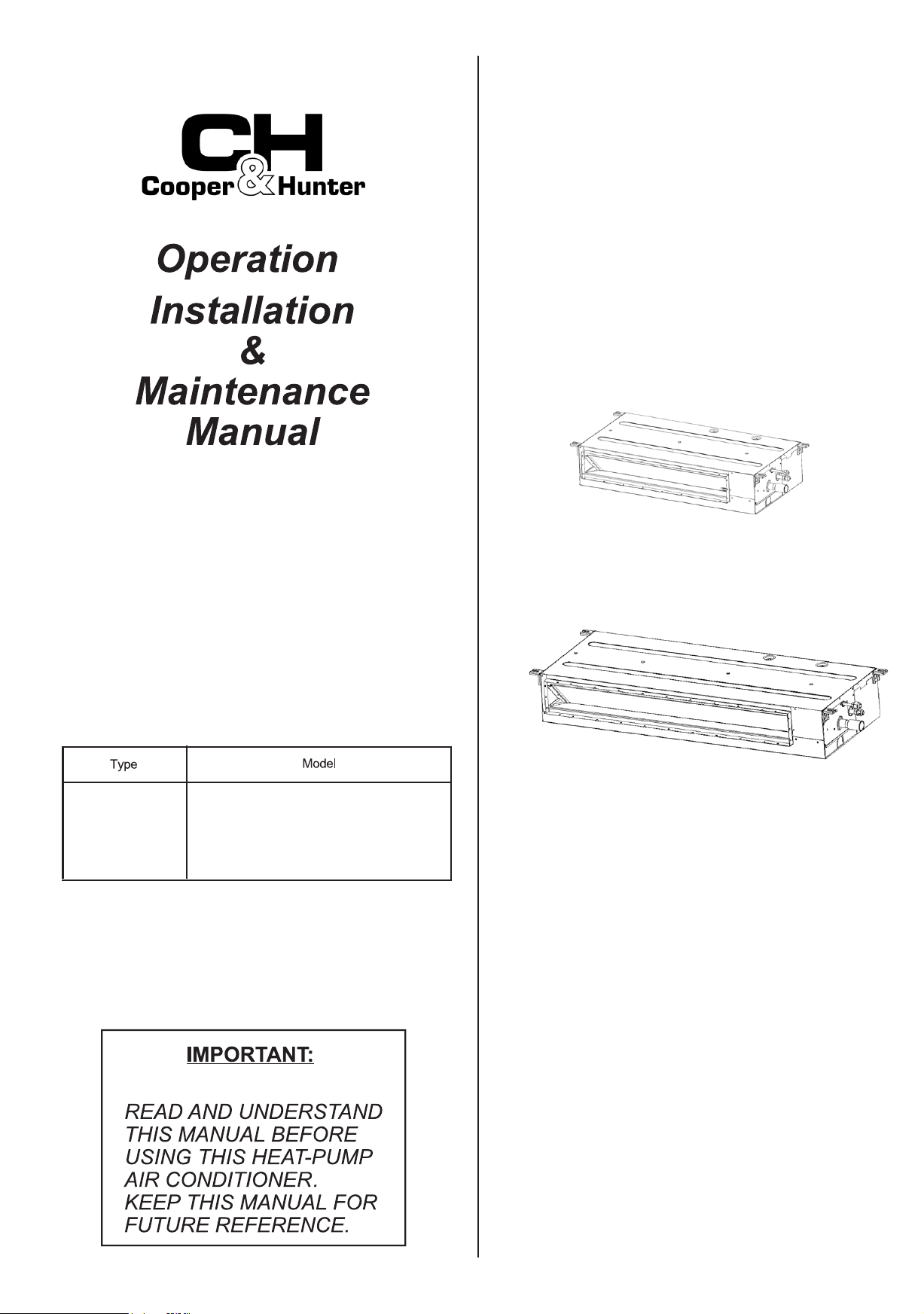
LOW HEIGHT
CEILING
DUCTED
TYPE
CHV-05SDLSP,CHV-07SDLSP
CHV-09SDLSP,CHV-12SDLSP
CHV-15SDLSP,CHV-17SDLSP
CHV-19SDLSP,CHV-22SDLSP
CHV-24SDLSP
ORIGINAL INSTRUCTIONS
- VRF INDOOR UNIT -
i
This manual should be considered as a permanent part of the air conditioning equipment. Please keep it properly.
We pursue a policy of continuous improvement in design and performance of products. The right is therefore reserved
to change specifications without notice.
Our company shall not be held responsible for any occasional damage to the air conditioner that arises during its
operation in specific environment.
This air conditioner must be used as a general air conditioner, and shall not be used for drying clothes, freezing foods,
cooling or heating and other purposes.
Please don't install the air conditioner in the following environments. Otherwise, fire, machine deformation or failure may
arise.
*
Places with spatter of oil (including machine oil).
Places with inflammable gases.
*
Places with sulfurated gases or silicon (e.g. hot spring, etc.).
*
*
Coastal areas with much salt or the places exposed to strong acids or bases
that may cause corrosion to machine.
●
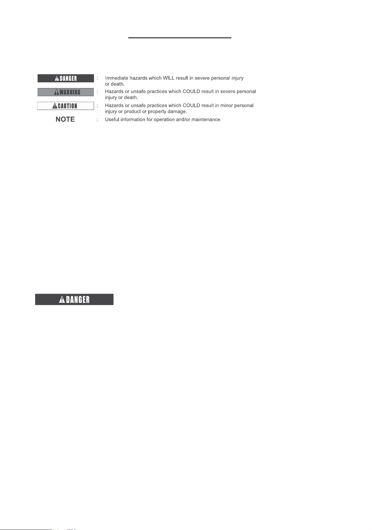
Signal words (DANGER, WARNING, CAUTION, and NOTE) are used to indicate hazard seriousness.
Definitions of the hazard levels are provided below with respective signal words.
●
IMPORTANT NOTICE
●
●
●
●
●
●
Do not orient the air outlet immediately to animals and plants, since this may cause adverse effects thereon.
The installation and service engineering have to comply with local standards, laws and regulations.
As an "appliance inaccessible to the public", the installation height of indoor unit of the air conditioner shall be at
least 98-27/64 in.(2.5m).
This air conditioner can only be installed by dealers or professionals. The installation by user may lead to water
leakage, electric shock or fire.
In case of any question, please consult the dealer or the service center designated by our company.
●
●
●
●
For environmental protection, please don't dispose of the product casually. Our company can provide recycling service
based on relevant regulations, and provide replacement parts according to relevant standards.
Refer to the instruction manual for complete machine (outdoor unit) for product standard for indoor unit.
Refer to Installation & Maintenance Manual of outdoor unit for temperature operation range.
●
●
lease dont perform installation ors suc as refrigerant piping connection drain pipe connection and iring connection.
iolations ma result in sstem leaage electrical failure or fire.
●
o not pour ater into te indoor or outdoor unit. is macine is an electric product tat ma deelop serious electric
failure en eposed to ater.
●
o not open te serice coer of indoor or outdoor units itout turning te main poer suppl oterise tis ma
ring aout serious safet accident.
●
o not touc or adust safet deices inside te indoor or outdoor units. If te are touced or readusted serious accident
ma arise.
●
Refrigerant leakage may bring about oxygen deficit-induced respiratory difficulty. In case refrigerant leakage is detected,
please turn off the main switch immediately, extinguish any naked flame, and contact service dealer.
●
Mae sure air tigtness test is performed.
Refrigerant R is nonflammale nontoic and odorless and ma produce toic gases en eposed to open flame.
ince tis refrigerant gas is eaier tan air it ma result in lac of ogen tere leading to reating difficulties en
te area near te ground is filled it tis gas. erforming lea detection and gas tigtness test it ogen acetlene or
oter flammale and toic gases ma cause eplosion so nitrogen is recommended for tis test.
●
e standards for safe refrigerant leaage in construction and sstem operation are determined ased on local regulations
or standards.
●
se it medium or iger sensing speed it an operating time of . seconds or less or electric soc or
fire ma arise.
●
or installation te refrigerant piping must e firml connected efore te operation of compressor. or repair te
refrigerant piping must e moed andled and remoed after te stop of compressor.
●
lease dont sortcircuit te protectie deice e.g. te pressure sitc etc. during operation since tis ma cause fire
or eplosion.
●
o not stamp on te macine or place sundries tereon.
●
o not put etra materials on or in te macine.
is air conditioner must e sericed professional maintenance personnel.
Rooms are recommended to e entilated once eer ours.
ote
●
eat pump air conditioner ma malfunction under te folloing conditions
*
e poer aailale from poer transformer is less tan or eual to te electrical poer of air conditioner.
e ecessiel sort distance from te poer cord of air conditioner to an igpoer electrical euipment results in
etremel ig inductie surge oltage in te poer cord of air conditioner.
*
●
●
CHECKING PRODUCT RECEIVED
●
●
●
●
●
●
●
●
●
●
●
o not use an spras suc as insecticide lacuer air spra or oter flammale gases itin approimatel meter
from te sstem.
If te eart leaage reaer is freuentl actiated please stop te sstem and contact our local dealer or ruor
serices.
Mae sure te ground ire is securel connected. e improper grounding of macine ma lead to electrical failure.
lease dont connect te ground ire to gas pipes tap ater pipes ligtning rods or pone ground ires.
Mae sure tere are no flammale materials around during raing operation. lease ear leater gloes to preent
frostite en filling refrigerant.
reent rats or oter small animals damaging te iring and electrical components. itten unprotected parts ma cause
a fire.
irml fi te connection ires. e eternal force of terminal ma result in looseness of terminal tat ma cause a fire.
Mae sure te air conditioner is installed it enoug strengt of fiation oterise te air conditioner ma fall or topple
oer ic ma ring aout macine damage or personal inur.
lease follo te installation instructions and related regulations and standards for electrical construction oterise
electrical failure or fire ma occur due to inadeuate capacit or inconsistent specifications.
eer fail to use specified iring and select correct iring since failure to do so ma cause electrical failure or fire.
lease mae sure te outdoor unit is not coered it sno or ice efore use.
●
pon receipt of tis product cec it for an sipping damage.
laims for damage eiter apparent or concealed sould e filed immediatel it te sipping compan.
ec te model numer electrical parameters poer suppl oltage and freuenc and accessories to determine if
te are correct. e standard operation metod for te macine is descried in te present manual.
lease contact local dealer en prolem arises.
Our company sall not e responsile for an conseuence of te modification to macine performed itout its
ritten consent.
IMPORTANT NOTICE
Correct Disposal of this product
This marking indicates that this product should not be disposed with other
household wastes. To prevent possible harm to the environment or human
health from uncontrolled waste disposal, recycle it responsibly to promote the
sustainable reuse of material resources. To return your used device, please use
the return and collection systems or contact the retailer where the product was
purchased. They can take this product for environmentall safe recycling.

15
. afet ummar
. nit escription
.
art ame
. Indoor nit
. efore peration
. utomatic ontrol
.
roulesooting
. If roule till Remains
. o peration
. ot ooling or eating ell
. is is ot normal
ection Installation & Maintenance Manual
.
.
afet ummar
ecessar ools and Instrument for Installation
ale of ontents
1
1
1
1
3
3
4
4
4
4
4
5
5
6
6
6
6
6
7
9
9
10
ection peration Manual
.
ransportation and andling
. ransportation
. andling of Indoor nit
.
Indoor nit Installation
. actorupplied ccessories
. Initial ec
. Installation and Repair of ilter creen
. Indoor nit Installation
.
Refrigerant iping or
. iping Materials
. iping onnection
.
rain iping
.
lectrical iring
. eneral ec
. lectrical iring onnection
.
est Run
.
rotection and ontrol eices
.
ield peration
. pecifications of ield onnected oer ord
. etting of I itc
. etting of ternal tatic ressure
11
12
12
12
13
13
14
14
15
7
6

●
Do not have the indoor unit or outdoor unit exposed to
water. All these parts are designed with electronic
components that may cause short circuit when exposed to
water.
●
Do not touch or adjust safety devices inside the indoor or
outdoor units. If these devices are touched or readjusted, it
may cause a serious accident.
●
Do not open the service cover or access the indoor or
outdoor units without turning OFF the main power supply.
●
Refrigerant leakage can cause difficulty with
breathing due to insufficient air.
●
Do not use any sprays such as insecticide, lacquer, hair
spray or other flammable gases within approximately 1
meter from the system.
●
If the indoor switchboard or fuse is frequently cut off,
please take the air-conditioning system out of service
and contact our agency.
!
!
1
1. Safety Summary
Table 2.1 Capacities of Indoor Units
Section 1 Operation Manual
●
This appliance can be used by children aged from 8
years and above and persons with reduced physical,
sensory or mental capabilities or lack of experience
and knowledge if they have been given supervision or
instruction concerning use of the appliance in a safe
way and understand the hazards involved. Children
shall not play with the appliance. Cleaning and user
maintenance shall not be made by children without
supervision.
It is recommended that the room be ventilated
every 3 to 4 hours.
Note
2. Unit Description
●
This heat-pump type air conditioning unit can consist of
one outdoor unit and several indoor units. Detailed
configurations are stated in the corresponding
installation & maintenance manual for outdoor unit.
This heat-pump type air conditioner is applicable for
refrigeration, heating, dehumidification and air supply,
etc. These features are controlled with a remote control
(option).
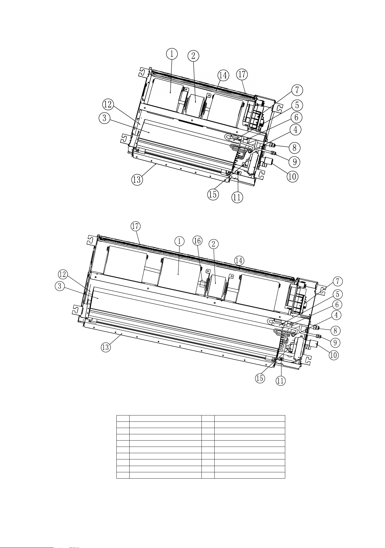
3.1 Indoor Unit
Refer to “ig.3.1 Ducted Type Indoor Unit”
3. Part Name
ominal apacit tu
Indoor nit
ucted pe
2
Name
No.
Name
1
2
4
3
6
7
5
8
Centrifugal Fan
Motor
Heat Exchanger
Electronic Expansion Valve
Filter
istriutor
Electric Box
Refrigerant Gas Pipe Connection(φa Flare)
Coupling (Models 19~24)
Drain Pump
Drain Pan
Air Outlet
Air Inlet
Float Switch
Drain Piping Base
16
13
15
14
11
12
10
9
No.
Refrigerant Liquid Pipe Connection(φb Flare)
Models 05~17
Models 19~24
17
Filter Screen
Fig. 3.1 Ducted Type Indoor Unit
3
The units that have been left unused for a long period of
time shall be electrified for more than 4 hours before
startup. Do not start the machine immediately after power-
on since this may cause damage to compressor due to
inadequate warm-up of lubricating oil.
Please check if the outdoor unit is covered with ice or
snow. If yes, please remove the ice or snow with warm
water. However, the water temperature shall not exceed
122°F since this may cause damage to plastic parts.
Turn off the main power supply if the machine is expected
to be left unused for more than 3 months, because the oil
heater band consumes power even if the compressor is
not in service. You are recommended to entrust
maintenance personnel to check the unit before startup.
Set the temperature properly. Set the temperature 2°F
lower than expected for heating, and set it 2°F higher than
expected for refrigeration so as to save resources.
Do not open doors and windows frequently during the
operation of air conditioner.
4. Before Operation
5. Automatic Control
This system is designed with the following features.
Note
Please keep the main power supply ON unless the
system is left unused for long. By doing so, the automatic
drainage device starts to function when the level of
accumulated water in machine exceeds the predefined
level.
Three-Minute Stop Protection
To protect the compressor, it is prevented for at least 3
minutes from functioning after its stop. The compressor
automatically gets started in 3 minutes.
Three-Minute Operation Protection
Ensure the compressor runs at least for 3 minutes (if the
compressor runs for less than 3 minutes, it can't stop
unless 3 minutes elapse even if all indoor temperatures
reach the set values). However, the compressor that
runs for less than 3 minutes can be brought out of
service with the remote control.
Oil Return Operation
When an indoor unit is out of service for more than 2
hours during refrigeration, it will run for a few minutes
automatically to prevent the detention of refrigeration oil
in the indoor unit in stopped state.
Freeze Protection during Refrigeration
When the outlet air temperature of indoor unit is
excessively low, refrigeration may be automatically
switched to air supply mode, in which the unit runs for a
period of time to avoid frosting on indoor heat
exchanger.
Cold Air Prevention
To prevent the output of cold air from indoor unit in
heating mode, the fan runs at low speed. The fan speed
is set based on outlet air temperature of indoor unit.
Control of Indoor Fan during Defrosting
The indoor fan is out of service during automatic
defrosting of outdoor unit.
Surplus Heat Output from Indoor Unit
Upon completion of heating, the indoor fan will keep on
running at low speed for approx. 2 minutes to reduce the
temperature of machine body.
Automatic Defrosting
Press "Run/Stop" key to stop heating. The outdoor unit
can automatically detect frost and automatically perform
defrosting for up to 10 minutes.
Overload Protection
Heating stops when outdoor temperature is excessively
high during heating. The heating resumes when the
outdoor temperature drops to a certain level.
Note
If the unit stops due to power breakdown, the system will
not automatically get into service even if power supply is
restored.
Please restart the unit from Step 1. The settings will not get
lost in the case of extremely short power-off time
(within 2 seconds). The system will come into operation
automatically in approx. 3 minutes.

!
4
6. Troubleshooting
When overflow of drain water from the indoor unit occurs,
stop the operation and contact your contractor.
When you smell or see white smoke coming from the
unit, turn OFF the main power supply and contact your
contractor.
6.1 If Trouble Still Remains
If the trouble still remains even after checking the following,
contact your contractor and inform them of the following
items.
(1) Unit Model & Name
(2) Content of Trouble
(3) Alarm Code No. on Liquid Crystal Display
6.2 No Operation
Check whether the SET TEMP is set at the correct
temperature.
6.3 Not Cooling or Heating Well
6.4 This is Not Abnormal
Smells from Indoor Unit
Smell adheres on indoor unit after a long period of
time. Please clean the filter screen and air-inlet grille or
keep the working space well ventilated.
Sound from Deforming Parts
During system startup or stop, an abrading sound
might be heard. However, this is due to thermal
deformation of plastic parts t is not abnormal.
Steam from Outdoor Heat Exchanger
During defrosting operation, ice on the outdoor heat
exchanger is melted, resulting in steam generation.
Refrigerant Flow Sound
While the system is being started or stopped, sound
from the refrigerant flow may be heard.
Check for obstruction of air flow of the outdoor or indoor
units.
Check if too many heat sources exist in the room.
Check if the air filter is clogged with dust.
Check to see if the doors or windows are opened or not.
Check if the temperature condition is not within the
operation range.

!
!
2. Necessary Tools and Instrument for Installation
5
Since the pressure of new refrigerant R410A is 1.4 times that of traditional refrigerant, its performance
is susceptible to impurities like moisture, scale and grease, etc. It's essential to remove the moisture,
dust, other refrigerants or refrigerant oils from the refrigeration system. Hence, the failure to use
specified materials and tools may result in explosion, personal injury, refrigerant leakage, electrical
failure or fire.
DANGER
Note: When in immediate contact with refrigerant, please use the installation tools and instruments
dedicated to the new refrigerant.
Section 2 Installation & Maintenance Manual
1. Safety Summary
Please don't perform installation works such as
refrigerant piping connection, drain pipe connection,
and electrical wiring connection.
Check that the ground wire is securely connected.
Connect a fuse of specified capacity.
Do not install the indoor unit, outdoor unit, wired
control and cable within approx. 39-13/32 inch. from
strong electromagnetic wave radiators such as medical
equipment.
Tool
No.
Tool
1
2
4
3
5
8
Phillips Screwdriver
Vacuum Pump
Refrigerant Gas Hose
Spanner
Copper Pipe Bender
Megohmmeter
Pipe Cutter
Brazing Kit
Clamper for Solderless Terminals
Leveler
Gauge Manifold
Cutter for Wires
Gas Leak Detector
Charging Cylinder
15
12
14
13
10
11
9
No.
Hexagon Wrench
Hoist (for Indoor Unit)
16
Ammeter
17
Voltage Meter
18
6
7

3.
Transportation and Handling
3.1 Transportation
Transport the product as close to the installation location
a po before unpacking.
Do not put any material on the product.
Handling of Indoor Unit
Do not put any foreign material into the indoor unit and check
to ensure that none exists in the indoor unit before the
installation and test run. Otherwise, a fire or failure, etc. may
occur.
Be sure not to damage insulation materials of unit’s surface
during lifting operation.
!
!
!
6
Do not install the indoor unit in a flammable environment
to avoid fire or an explosion.
●
Do not install the indoor unit outdoors. If installed
outdoors, an electric hazard or electric leakage will occur.
!
Please contact the dealer if the accessories are not
delivered with machine.
It is recommended that indoor units be installed
higher than 98-27/64 in. from the floor level.
4.1 Factory-Supplied Accessories
Check to ensure that the following accessories are packed
with the indoor unit.
4.2 Initial Check
Install the indoor unit with a proper clearance
around it for operation and maintenance
working space, as shown in Fig. 4.1.
Models 05
~
24
Top View
Fig. 4.1 Space Around Indoor Unit
4.
Indoor Unit Installation
Install the indoor unit as per national standard.
!
!
Indoor unit must be so positioned that the indoor
temperature is distributed evenly.
There should be no obstruction that blocks air flow indoors
and at air vent.
Do not install the indoor unit in a machinery shop or
kitchen where vapor from oil or its mist flows to the indoor
unit.
The oil will deposit on the heat exchanger, thereby
reducing the indoor unit performance, and may deform and
in the worst case, break the plastic parts of the indoor unit.
(Unit:in.)
Rear
Electrical Cabinet
Manhole
Front
≥17-23/32
3-15/16
5-33/64
23-5/8
23-5/8
≥39-3/8
≥23-5/8
1.. Where the ceiling
not removable, please
arrange a necessary
service access under
the indoor unit.
2.2.The service access
shall be so arranged
that the electric box
cover/internal
components can be
removed/repaired in a
convenient manner.
Accessory Bag for
Magnetic Ring
Arranged around the Power Cord of indoor
Unit
7
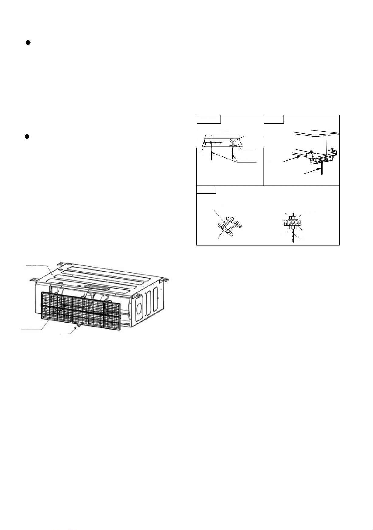
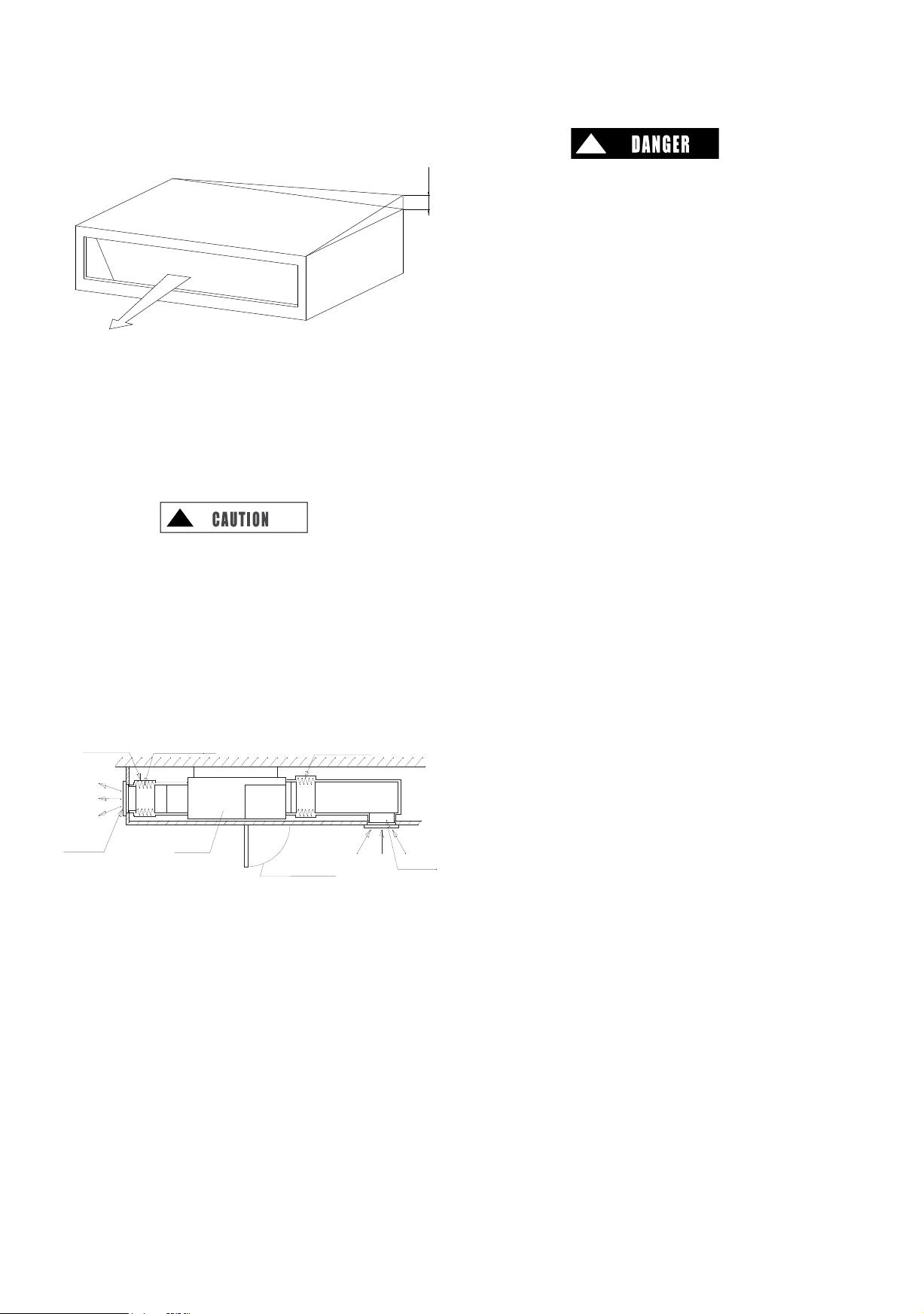
4.3 Installation and Repair of
Filter Screen
4.3.1 Installation of Filter Screen
(1) As shown in the figure below, remove the filter screen
fastening screw;
(2) Draw the filter screen down until the upper rib gets out
of the slot;
(3) Pull out the left and right ribs of filter screen out of the
machine, and take out the filter screen;
(4) Clean and reinstall the filter screen following the
reverse steps of its removal.
4.3.2 Maintenance and Servicing of
Filter Screen
Take down the filter screen from the machine during
maintenance, and remove the dust with dust collector or
water. To remove stubborn dirt, please dissolve neutral
detergent in cold water, and clean the screen therein.
Take out the well cleaned filter screen, dry and reinstall it.
Depending on local air quality, please clean the filter
screen every 3 months operation of air conditioner.
4.4 Indoor Unit Installation
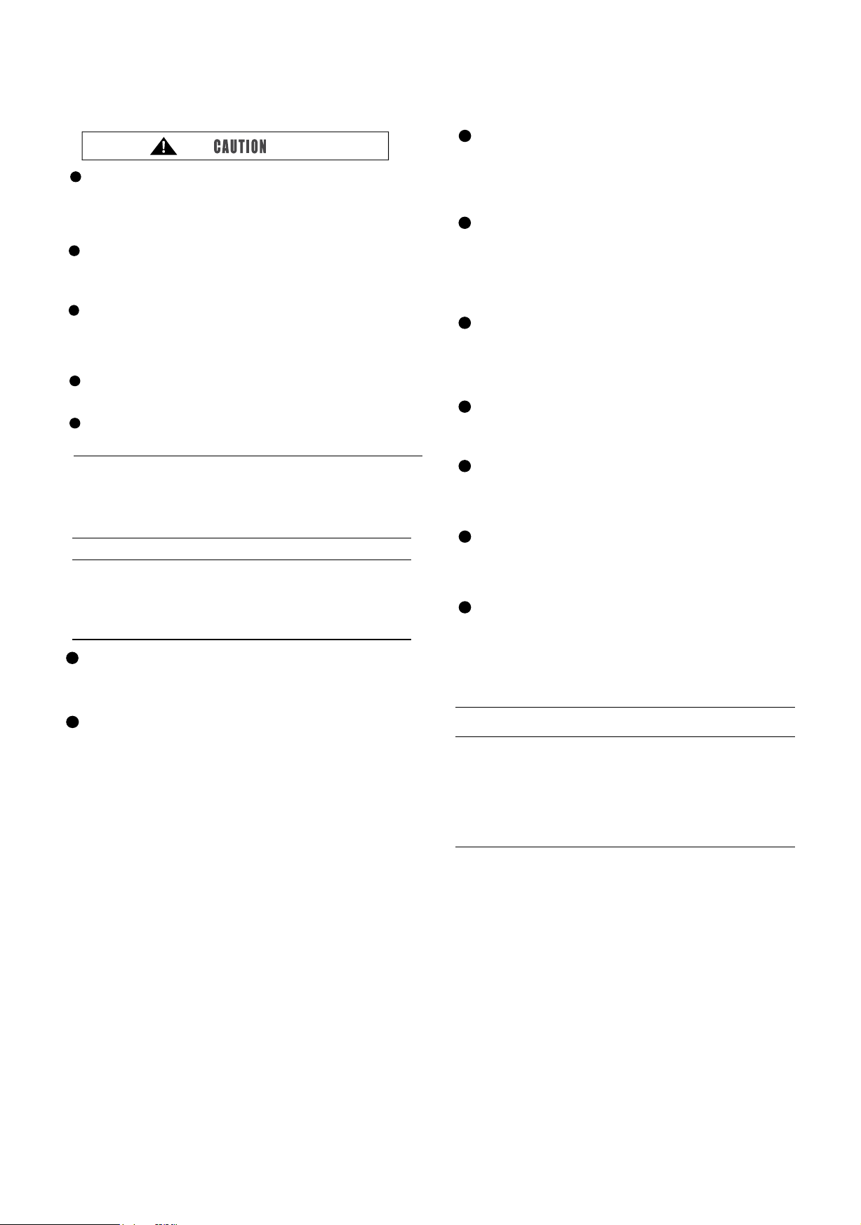
4.4.1 Suspension Bolts
Fig. 4.3 Mounting the Suspension Bolts
Fig. 4.2 Installation of Filter Screen
Indoor Unit
Air Filter
Screw
(1) Decide upon appropriate mounting position and
orientation by carefully taking into consideration the piping,
wiring and repair.
(2) Fig. 4.3 shows how to install suspension bolts.
● For Concrete Slab
5-29/32 to 6-5/16
Screw in
(221 to 331 lbs)
Concrete
Steel
Suspension
Bolt
(W3/8 or M10)
● For Steel Beam
I Beam
Suspension Bolt
(W3/8 or M10)
●
For Wooden Beam
Wooden Rib
2-3/8 to 3-17/32
in. square
timber)
Wooden Beam
Nut
Nut
Square Washer
Square Washer
Suspension Bolt
Pay attention to the following points when the indoor unit is
installed in a hospital or other facilities where there are
electronic waves from medical equipment, etc.:
(A) Do not install the indoor unit where the electromagnetic
wave is directly radiated to the electric box, wired control
cable or wired control.
(B) Install the indoor unit and components as far a po
or at least 118-7/64 inch. from the electromagnetic wave
radiator.
(C) Prepare a steel box and install the wired control in it.
Prepare a steel conduit tube and wire the control cable in it.
Then, connect the ground wire with the box and the tube.
(D) Install a noise filter when the power supply emits
harmful noises.
To avoid any corrosive action to the heat exchangers, do not
install the indoor unit in an acid or alkaline environment.
(in.)

8
05
12
19
24
27-23/64
46-19/64
29-37/64
48-1/2
15 17
35-43/64
37-7/8
Nut
Indoor Unit
Washer
Nut
Approx. 1/2
7-9/16
Fig. 4.4 Suspension Bolt
Size
Indoor Unit Capacity (kBtu/h)
Fig. 4.5 Installation of Indoor Unit
Fig. 4.6 Suspension Bolts and Nuts
Fig. 4.7 Handling Method
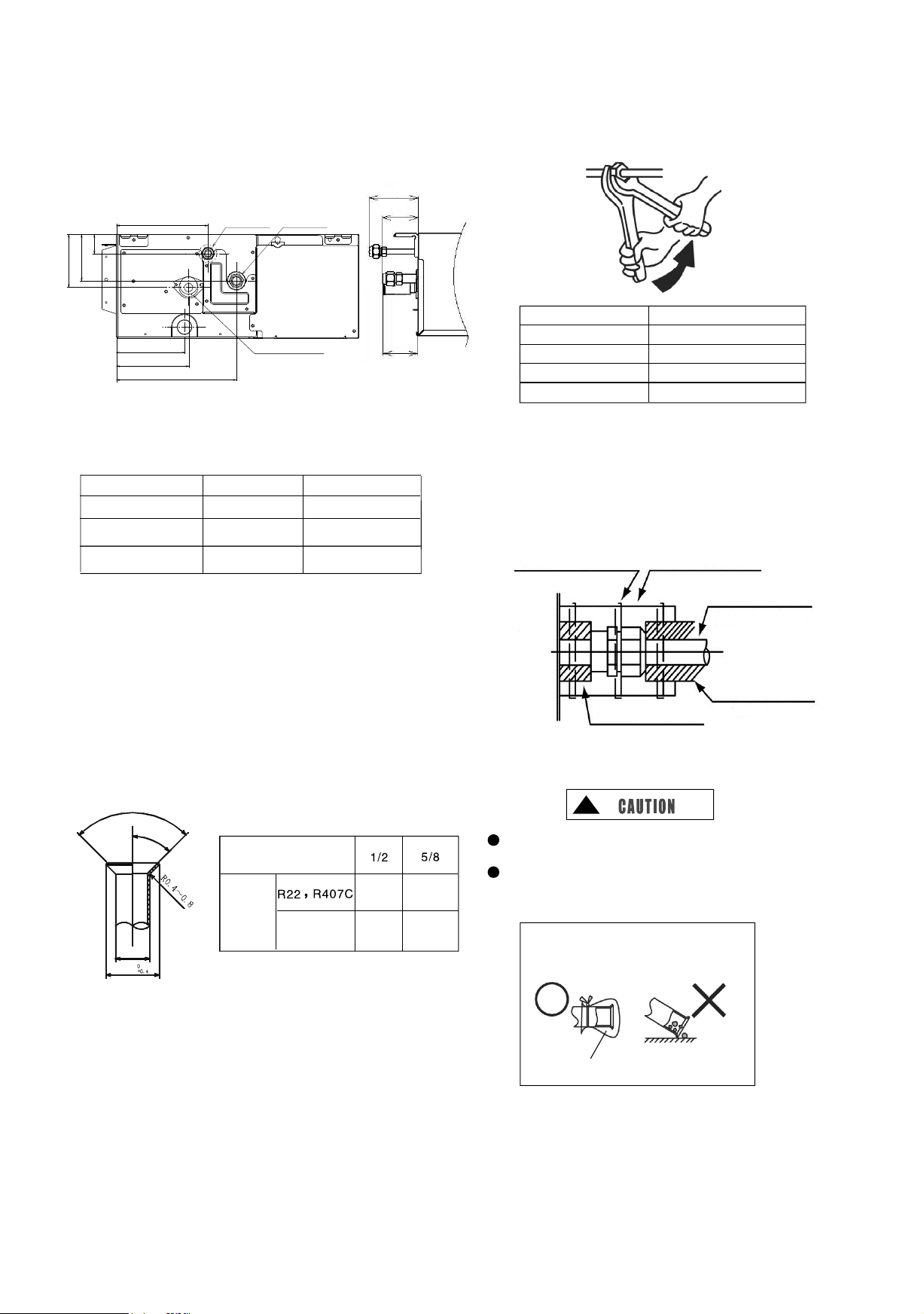
4.4.2 Suspension Bolt and Pipe
Connection Points
(1) Indicate the location of suspension bolt, and the
connection points of refrigerant pipe and drain pipe.
(2) Installation dimensions are shown in Fig. 4.4.
a (Suspension Bolt Size)
14-49/64 (Suspension Bolt Size)
Outlet Direction
Top View
4.4.3 Installation of Indoor Unit
Indoor unit is installed as shown in Fig. 4.5.
Installation of Field-Supplied Parts
Suspension Bolt 4-M10 or W3/8
Nut 8-M10 or W3/8
Washer 8-M10 or W3/8
Suspension Bolt (4-M10 or W3/8)
(Field Supplied)
Nut and Washer
(4-M10 or W3/8)
(Field Supplied)
Support Leg
(1) How to Install Suspension Bolt and Nut
Mount nuts to the four bolts as shown in Fig. 4.6.
(2) Installation of Indoor Unit
* Place the left bracket on the nut and washer of
suspension bolt as shown in the figure below.
* Make sure the left bracket is properly placed on the nut
and washer, and put the right bracket of indoor unit on the
nut and washer.
(The suspension bolt can be slightly shifted for the
placement of indoor unit.)
Nut and Washer
Suspension Bolt
Indoor Unit
Suspension Bracket
Suspension Bracket
17-33/64
1-1/16
5/16
Unit: in.
Unit: in.
Unit: in.
5.1 Piping Materials
(1) Prepare field-supplied copper pipes.
(2) Select clean copper pipes. Make sure there is no dust and
moisture inside. Blow the inside of the pipes with nitrogen or dry
air, to remove any dust or foreign materials before connecting
pipes.
(3) Select copper pipes based on Fig. 5.2.
9
Flexible Canvas Connection
Thermal
Insulation Material
Flexible Canvas Connection
Return Air Inlet
Air Outlet
Level
Fig. 4.8 Top Surface Inclination Degree
Service Access
(with Filter Screen)
Fig. 4.9 Air Duct Connection
4.4.4 Leveling of Indoor Unit
(1) Check to ensure the top surface is level, and
measure the max. top surface inclination degree.
(2) As shown in Fig. 4.8, the rear part of indoor unit is slightly
lower than its front part (by 0~13/64 in.) so as to facilitate
drainage.
(3) Tighten the suspension nut upon completion of
adjustment. It's essential to apply thread locking agent to
avoid nut looseness.
!
Please cover the machine with plastic cloth during installation
so as to keep it clean.
4.4.5 Air Duct Connection
Air duct is connected to indoor unit via canvas hose to
effectively isolate noise and vibration.
<Example>
5.
Refrigerant Piping Work
!
Use refrigerant R410A in the refrigerant cycle. Do not charge
oxygen, acetylene or other flammable and poisonous gases into
the refrigerant cycle when performing a leakage test or an air-
tight test. These types of gases are extremely dangerous and
can cause an explosion. It is recommended that nitrogen be
used for these tests.
13/16 inch
(23-5/8 in.×23-5/8 in.)
10
05~17
※
※
※
22, 24
19
※ Since the nut cap connected at gas pipe is
designed exclusively for R410A, the piping flaring
connected for off-factory installation is adjusted as
compared with R22 and R407C. Please perform the
processing operation based on the dimensions shown
below: (See Fig. 5.3)
Outside Diameter of
Piping(a)
Outside
Diameter
of
Flaring (D)
R410A
45°±2°
90°±2°
a
D
5.2 Piping Connection
(1) Piping connection points are shown in Figs. 5.1 and 5.2.
Refrigerant
Liquid Pipe
Refrigerant
Gas Pipe
Drain Pipe (for
Drain Pump)
Fig. 5.1 Piping Connection Points
Indoor Unit Capacity (kBtu/h)
Gas Pipe
Liquid Pipe
Fig. 5.2 Pipe Size
Unit: in.
Fig. 5.3 Flaring
(2) As shown in Fig. 5.4, two spanners shall be used for
tightening the nut.
Pipe Size (inch(mm))
Tightening Torque (ft.·lbs(N.m))
Fig. 5.4 Nut Tightening Torque
(3) Insulate the refrigeration piping with field-supplied
insulating pipe upon completion of refrigerant pipe
connection. See Fig. 5.5.
Wire Tie (Option)
Insulating Pipe (Option)
Refrigerant Piping Work
(Field Supplied)
Insulating Pipe
(Field Supplied)
Thermal Insulation Material (Option)
Indoor Unit
Side
Fig. 5.5 Thermal Insulation of Pipes
!
Cap the end of pipe when the pipe is to be inserted
through a hole.
Do not put pipes on the ground directly without a cap or
vinyl tape at the end of the pipe.
Do not put pipes on the ground directly
Correct
Incorrect
Blocked with tape or plug
(4) Discharging and Charging Refrigerant
Follow the Installation & Maintenance Manual for
outdoor unit.
3-53/64
3-25/64
1-3/8
6-35/64
5-5/64
5-15/64
8-21/32
2-31/64
2-19/32
3-35/64
1/2(12.7)
5/8(15.88)
1/4(6.35)
1/4(6.35)
3/8(9.53)
41/64
21/32
49/64
25/32
1/4(6.35)
3/8(9.53)
1/2(12.7)
5/8(15.88)
Unit: in.
Unit: in.(mm)
5/8(15.88)
14.75(20)
29.50(40)
44.25(60)
59.00(80)

(1)
11
! !
Excessive and inadequate refrigerant is a leading cause
of system anomaly. Please inject the right amount of
refrigerant.
6.
Drain Pipe
(1) See Fig. 6.1 for connection point of drain pipe.
(2) Find a PVC pipe with an outside diameter of 1-1/4 in.
(3) Fix the PVC pipe to drain pipe through adhesive and
factory-supplied clamp. The downward inclination of
drain pipe is 1/25~1/100 in.
(4) Make thermal insulation after the proper connection
of drain pipe.
Pipe Support
(Field Supplied)
90º Bend (VP25)
(Field Supplied)
Drain Lift Pipe (PVC Pipe, VP25)
(Field Supplied)
Indoor Unit
Drain Pipe (L11-13/16)
(Option)
Drain Pan
Drain Pump
Rubber Stopper
(Accessory)
Drain Pipe (PVC Pipe,VP0.98)
(Field Supplied)
1/25~1/100 downward inclination
14-23/32~35-7/16 (Lift)
Fig. 6.1 Drain Pipe
Where the relative humidity of air inlet or ambient air
exceeds 80%, an auxiliary drain pan shall be fabricated at
installation site and placed under the indoor unit, as shown
in Fig. 6.2.
Indoor Unit
Auxiliary Drain Pan
(Field Supplied)
Drain Outlet
Fig. 6.2 Drain Pan
!
The drain pipe installed shall slope down; otherwise, the
condensate may flow back and leak into the room when
the indoor unit is turned off.
(2) The drain pipe shall not be connected with sewage pipe
or other drain pipes.
(3) Where the main drain is connected to other indoor units,
each indoor unit must be higher than the main. Select
drain pipes in ample size depending on the refrigerating
capacity and quantity of indoor units.
(4) Check if water flows without obstruction following the
procedure shown below after the proper connection of
wires and drain pipes.
a. Turn on the power
b. Fill the drain pan with 68oz(2L) or 84oz(2.5L) of water.
c. Check and ensure the water flows without obstruction
and no leakage exists. Pour 68oz(2L) of water if no
water flows out of pipe end.
2-9/32
2-9/32
Unit:(in.)
63/64
63/64
9-1/4
14-31/32
63/64
7-13/32
11-15/32
1-31/32~22-11/16

12
Turn OFF the main power switch to the indoor unit and
the outdoor unit and wait for at least minutes before
electrical wiring work or a periodical check is performed.
Check to ensure that the indoor and outdoor fans have
stopped before electrical wiring or a periodical check.
Protect the wires, drain pipe, electrical parts, etc. from
rats or other small animals. If no protection is arranged,
rats may gnaw at unprotected parts and at the worst, a
fire will arise.
Avoid the contact of wires with the refrigerant piping,
sheet metal edges and electrical components in unit.
Otherwise, the wire may be damaged or even cause fire.
Use ELB with medium sensing rate (earth leakage
breaker with action time being equal to 0.1 seconds or
less). The failure to do so may result in electric shock or
fire.
The wires must be firmly secured. External force applied
to terminals may cause a fire.
Never connect the power terminal block for air
conditioner to power cord. At the indoor unit side of air
conditioner, power wiring can be extended through a
power distribution box. Be sure to calculate the wiring
capacity carefully, since excessively low wiring capacity
may frequently cause fire.
Do not start the system before all check points are
thoroughly checked.
Fix the wire clamp body and its nuts to the wiring hole
of electric box using a torque of 0.74~0.89ft.lbs
(1.0~1.2N.m).
Connect the cable of wired control to the connectors
on the printed circuit board in electric box through the
wire clamp and wiring hole.
Connect power cord and the communication cables of
indoor and outdoor units to corresponding terminals of
electric box in the same way.
Upon completion of electrical wiring, the wire clamp nut
shall be manually tightened to block condensate and
insects.
7.
Electrical Wiring
!
!
Wrap the accessory packing around the wires, and plug
the wiring connection hole with the seal material to
protect the product from any condensate or insects.
Tightly secure the wires with the cord clamp inside the
indoor unit.
Secure the cable of wired control using the cord clamp
inside the electric box.
Tighten screws to the following torques.
7.1 General Check
Make sure that the field-selected electrical components
(main power switches, circuit breakers, wires, conduit
connectors and wire terminals) have been properly
selected according to the electrical data given in
"Technical Catalog I". Make sure the components comply
with National Electrical Code (NEC).
Check to ensure that the power supply voltage is within
±10% of the rated voltage.
Check the capacity of the electrical wires. If the power
source capacity is too low, the system cannot be started
due to the voltage drop.
Check to ensure that the ground wire is connected.
7.2 Electrical Wiring Connection
The electrical wiring connection for the indoor unit is shown
in Fig. 7.1.
M4:
M5:
M6:
M8:
M10:
0.74~0.96 ft.·lbs(1.0
~
1.3N·m)
1.48
~1.77
ft
.
·lbs(2.0
~
2.4N·m)
6.64~8.11 ft.·lbs(9.0
~
11.0 N·m)
13.28~16.96 ft.·lbs(18.0
~
23.0 N·m)
2.95~3.69 ft.·lbs(4.0
~
5.0 N·m)

05~24
13
Wire Clamp
Terminal
Block (TB)
Enlarged View of
P Part
Terminal Block
(TB) Wiring
Wired
Remote
Control
Wire
Commu
nication
Cable
Power
Cord
Wired Control
Communication
Wire Clamp Body
Hand-Operated Nut
Wire
Electric Box
Wire Clamp Nut
The tightening torque
is recommended to
be 0.74~0.89ft.lbs .
Enlarged View of R Part
(Wire Clamp Fixation Method
Diagram)
Fig. 7.1 Wiring Connection
8.
Test Run
The debugging shall be performed as per the Installation &
Maintenance Manual.
!
The machine can't be started unless all check points are
checked and ascertained.
(A) Check to make sure the terminal resistance to ground
exceeds 1MΩ; otherwise, the electrical leakage point must
be identified and repaired before startup.
(B) The shutoff valve of outdoor unit must be checked and
fully opened before the startup of unit.
(C) Make sure the main power supply has been kept ON
for over 4h so that the heater can heat the lubricating oil of
compressor.
Pay attention to the following precautions during system
operation.
(A) Do not touch any part at exhaust end, Because the
temperatures of case and pipeline at exhaust end of
compressor may reach 194°F(90°C) or more during
operation.
(B) Don't press the AC contactor button, since this may
lead to serious accident.
9.
Protection and Control Devices
Indoor Unit
Indoor Unit Capacity (kBtu/h)
Capacity of Fuse on Indoor
Unit Control Circuit
Freeze Protection
Temperature
Cut-out
Cut-in
Set Temperature
Difference
208/230V~60Hz
°F(°C)
°F(°C)
°F(°C)
A
5
32(0)
58(14)
36(2)

Electrical Parameters and Power Cord Size of Indoor Unit
14
10.
Field Operation
208/230V~
60Hz
Total Current (A)
Cable for Permanent Wiring(AWG)
14(2.5mm
2
)
05~07
09~12
15~17
19
22~24
0.47A
Indoor Unit Capacity (kBtu/h)
10.1 Specifications of Field Connected Power Cord
Power Supply
Max. Current
Power Cord
Specifications
(AWG)
Signal Wire
Specifications
(AWG)
DO NOT connect
wires in series when
the current exceeds
63A.
0.64A
0.74A
0.74A
1.12A
14(2.5mm
2
)
14(2.5mm
2
)
14(2.5mm
2
)
12(4.0mm
2
)
10(6.0mm
2
)
8(10.0mm
2
)
6(16.0mm
2
)
18(0.82mm
2
)
Note:
MCA: Min. Circuit Amps (A);
MOP: Max. Overcurrent Protective Device (A);
kW: Fan Motor Rated Output (kW) ;
FLA: Full Load Amps (A)
(1)
Use a shielded cable for the transmitting circuit and connect it to ground.
(2) Field wiring shall be in conformity to local laws and regulations, and all wiring operations
must be performed by qualified professionals.
(3) Once the power cord is damaged, the dealer or the professionals from designated
maintenance department must be contacted in a timely manner for repair and
replacement.

(1) DIP switch must be set with power sources of the indoor
and outdoor units in OFF state. Otherwise, the settings are
invalid.
(2) The location of DIP switch is shown in the figure below
(b)
Capacity Code Setting (DSW3)
No setup is required.
The code is set before delivery. This switch is used to
set the capacity of indoor unit.
15
(a)
(3) The PCB of indoor unit is furnished with 2 rotary
switches and 6 DIP switches that must be set based on the
following requirements before test run. The system must not
be started before the completion of DIP setup.
10.2 Setting of DIP Switch
(c) Model Code Setting (DSW4)
No setup is required. The code is set before delivery.
Note:
Symbol "■" indicates the location of DIP switch.
The position indicated in the diagram is in the factory-set
state.
!
The power supply shall be turned off before the setup of
DIP switch. Otherwise, the settings will be invalid.
Indoor Unit Setting
DSW6 (Tens Digit) RSW1 (Units Digit)
Setting Position
Insert a flat head screw
driver into the slot for setup
Ex.) Set machine No. 16
No.1 is ON
Setting 6
DSW6 and RSW1 are set to "0" before delivery.
When H-Net is used, up to 64 indoor units can be
connected.
When H-Net is not used, up to 16 indoor units can be
connected.
(d) Cooling System Code No. Setting (RSW2&DSW5)
The setup is needed. All are set to OFF before delivery.
Refrigerant System Setting
DSW5 (Tens Digit) RSW2 (Units Digit)
Ex.) Set system No. 5
Setting Position
Insert a flat head
screw driver into the
slot for setup
All set to OFF
Setting 5
DSW5 and RSW2 are set to "0" before delivery.
When H-Net is used, up to 64 indoor units can be
connected.
When H-Net is not used, up to 16 indoor units can be
connected.
(e) Safety Reset (DSW7)
* Factory setting.
* Once strong current is accidentally
connected to Terminals 1 and 2 of
TB2, the PCB fuse will be blown.
Then, it's necessary to correct the
wiring and then set switch No. 1 to
ON.
Performing external static pressure setup ("C5") on wired
remote control can change the static pressure. Please refer
to the Installation & Maintenance Manual for wired remote
control.
10.3 Setting of External Static Pressure
05~
0psf(0Pa)
0.21psf(10Pa)
0.63psf(30Pa)
02
01
24
Wired Remote Control
Setting
Indoor Unit
Capacity (kBtu/h)
External Static
Pressure
00 (Factory
Setting)
All indoor units must be numbered (RSW1&DSW6)
as shown in the figure below. The outdoor unit
numbering must start with "0".

08.2022 0
The oman is ommitted to ontinuous rodut imroement. We resere the right therefore to alter the rodut information at an time
and without rior announement.