Loading ...
Loading ...
Loading ...
8. Switch operation
○
When the switch trigger is depressed, the tool rotates.
When the trigger is released, the tool stops.
When releasing the trigger of the switch, the brake will
be applied for immediate stopping.
○
The rotational speed of the drill can be controlled by
varying the amount that the switch trigger is pulled.
Speed is low when the switch trigger is pulled slightly
and increases as the switch trigger is pulled more.
CAUTION
●
The motor rotation may be locked to cease while
the unit is used as drill. While operating the
driver drill, take care not to lock the motor.
●
If the motor is locked, immediately turn the power
off . If the motor is locked for a while, the motor or
battery may be burnt.
●
Do not tighten too strongly as the screw heads
will be damaged.
9. How to select rotational speed
CAUTION
●
The selection examples shown in Table 7 should
be considered as general standard. As diff erent
types of tightening screws and diff erent materials
to be tightened are used in actual works proper
adjustments are naturally necessary.
●
When using the driver drill with a machine screw
at HIGH (high speed), a screw may damage or a
bit may loose due to the tightning torque is too
strong. Use the driver drill at LOW (low speed)
when using a machine screw.
NOTE
The use of the battery in a cold condition (below
0 degree Centigrade) can sometimes result in the
weakened tightening torque and reduced amount of
work. This, however, is a temporary phenomenon,
and returns to normal when the battery warms up.
7. Tightening torque adjustment.
(1) Tightening torque
Tightening torque should correspond in its intensity to
the screw diameter. When too strong power is used,
the screw head may be broken or be injured.
Be sure to adjust the clutch dial position according to
the screw diameter.
(2) Tightening torque indication (See Fig. 11)
The tightening torque diff ers depending on the type of
screw and the material being tightened.
The unit indicates the tightening torque with the
numbers “1, 5, 10 ... 20” on the clutch dial, and a dot.
The tightening torque at position “1” is the weakest
and the torque is strongest at the highest number.
(3) Adjusting the tightening torque (See Fig. 11)
Rotate the clutch dial and line up the numbers “1, 5,
10 ... 20” on the clutch dial, or the dot, with the triangle
mark on the outer body. Adjust the clutch dial in the
weak or the strong torque direction according to the
torque you need.
Table 6 Tightening torque
Clutch dial
position
Tightening torque
1 Approx. 5.3 in.-lbs. (0.6 N-m)
5 Approx. 11.7 in.-lbs. (1.3 N-m)
10 Approx. 19.6 in.-lbs. (2.2 N-m)
15 Approx. 27.5 in.-lbs. (3.1 N-m)
20 Approx. 35.4 in.-lbs. (4.0 N-m)
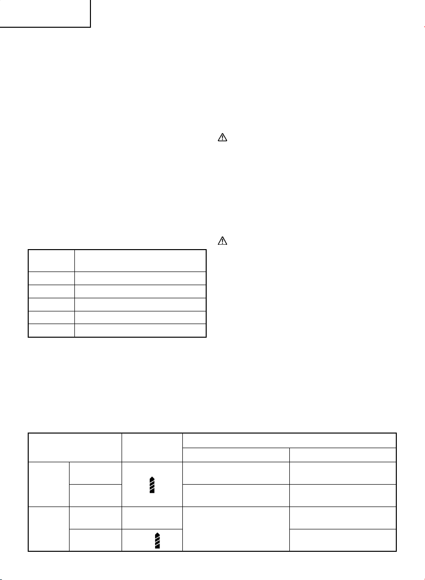
Table 7
Work Cap Position
Rotating speed selection (Position of the shift knob)
LOW (Low speed) HIGH (High speed)
Drilling
Wood
For 1 – 7/16 in. (36 mm) or
smaller diameters.
For 11/16 in. (18 mm) or smaller
diameters.
Metal ———
For drilling with a metal working
drill bit.
Screw
tightening
Small screw 1 – 20
For 1/4 in. (6 mm) or smaller
nominal diameter screws.
For 1/4 in. (6 mm) or smaller
nominal diameter screws.
Wood screw
1 –
For 5/32 in. (4.1 mm) or smaller
nominal diameter screws.
14
English
0000BookDS18DDX.indb140000BookDS18DDX.indb142020/05/1210:34:562020/05/1210:34:56
Loading ...
Loading ...
Loading ...