Owner's Manual and
Installation Instruction_
27-Inch Wide
GAS DRYERS
®
m_m
u_m_
IMPORTANT:
Read and follow all safety
and operating instructions
before first use of this product.
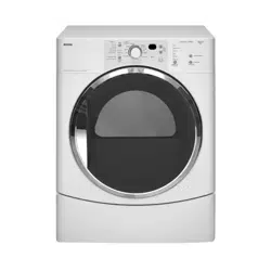
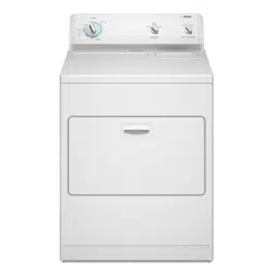
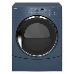
Your dryer may look different
from the dryer shown.
Sears, Roebuck and Co., Hoffman Estates, IL 60179 U.S.A.
PART NO, 3405603 PRINTED IN U.S.A.
WARNING: For your safety the information in this manual
mustbe followed to minimizethe risk of fire or explosion
or to prevent propertydamage,personalinjury,or death.
• Do not store or use gasoline or other flammable vapors and
liquids in the vicinity of this or any other appliance.
WHATTODO IFYOUSMELL GAS
• Do nottry to lightany appliance.
• Do nottouch anyelectrical switch; donotuse anyphonein
your building.
• Clearthe room,building,or area of all occupants.
• Immediatelycall your gas supplier from a neighbor's phone.
Follow the gas supplier's instructions.
• If you cannotreachyourgas supplier,call thefire department.
Installation and service must be performed by a qualified
installer,service agency,or the gas supplier.
BEFORE USING YOUR NEW DRYER
SEARS GAS DRYER WARRANTY
IMPORTANT SAFETY INSTRUCTIONS
INSTALLATION INSTRUCTIONS
OPERATING YOUR DRYER 22
LAUNDRY TIPS 29
CARING FOR YOUR DRYER
31
TROUBLESHOOTING 35
SEARS MAINTENANCE AGREEMENT 37
Please read this manual. It will help
you install and operate your new
Kenmore dryer in the safest and most
economical way.
For more information about the care
and operation of Kenmore appliances
call your nearest Sears store. You will
need the complete model and serial
numbers when requesting information.
'four dryer's model and serial numbers
are located on the Model and Serial
Number Plate.
Use the space below to record the model
number and serial number of your new
Kenmore Dryer.
Model No.
Serial No.
Date of Purchase
Keep this book and your Sears
Salescheck (receipt) in a safe place
for future reference.
3
FULL 1-YEAR WARRANTY
ON MECHANICAL AND
ELECTRICAL PARTS
For one year from the date of purchase,
wiqen this dryer is installed and operated
according to the instructions in the Owner's
Manual, Sear.'; will repair or replace any
mechanical or electrical parts in this dryer,
if defective in material or workmanship.
This warranty does not cover service
calls to correct improper installation,
including dryers that have been vented
with plastic or flexible foil.
If the dryer is subjected to other than
private family use, the above warranty
coverage is effective for only 90 days.
WARRANTY SERVICE IS AVAILABLE
BY CONTACTING THE NEAREST
SEARS SERVICE CENTER IN THE
UNITED STATES.
This warranty applies only while this
product is in use in the United States.
This warranty gives you specific legal
rights, and you may also have other
rights which vary from state to state.
Sears, Roebuck and Co., Dept. 817WA,
Hoffman Estates, IL 60179.
NOTE: Proper installation to comply
with the dryer's warranty is found in
the Installation Instructions of this
Owner's Manual.
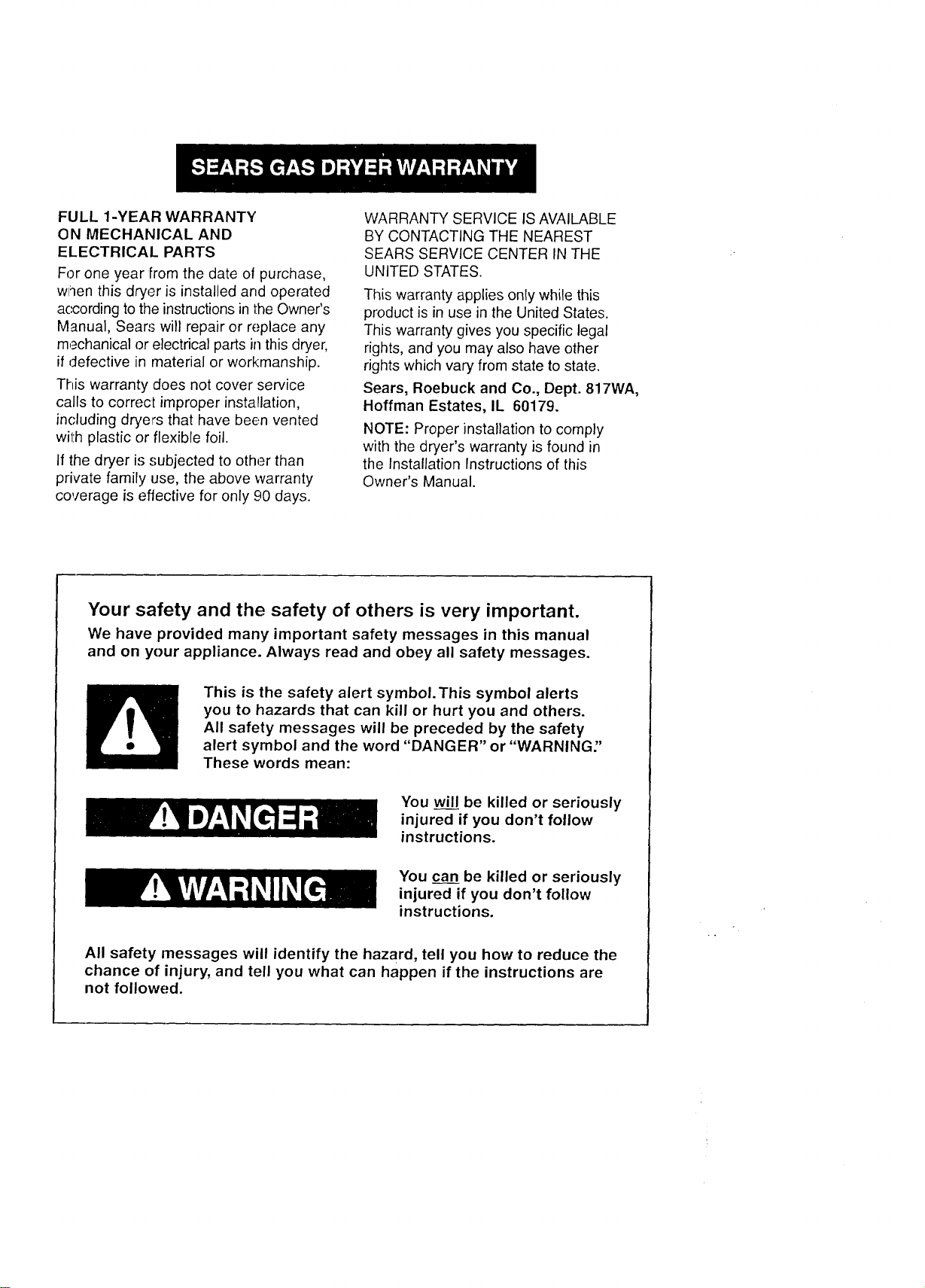
Your safety and the safety of others is very important.
We have provided many important safety messages in this manual
and on your appliance. Always read and obey all safety messages.
This is the safety alert symbol.This symbol alerts
you to hazards that can kill or hurt you and others.
All safety messages will be preceded by the safety
alert symbol and the word "DANGER" or "WARNING:'
These words mean:
You will be killed or seriously
injured if you don't follow
instructions.
You can be killed or seriously
injured if you don't follow
instructions.
All safety messages will identify the hazard, tell you how to reduce the
chance of injury, and tell you what can happen if the instructions are
not followed.
YOUR SAFE'TY IS IMPORTANT TO US.
WARNING: lb reduce the risk of fire,
electric shock, or injury to persons
when using your dryer, follow basic
precautions, including the following:
• Read all instructions before using
the dryer.
• Do not dry articles that have been
previously ('leaned in, washed in, soaked
in, or spotted with gasoline, dry-cleaning
solvents, other flammable or explosive
substances as they give off vapors that
could ignite or explode.
• Do not allow children to play on or in
the dryer. Glose supervision of children
is necessary when the dryer is used
near children.
• Before the dryer is removed from
service or discarded, remove the door
to the drying compartment.
• Do not reach into the dryer if the drum
is moving.
• Do not inst.all or store this dryer where
it will be exposed to the weather.
• Do not tamper with controls.
• Do not repair or replace any part of the
dryer or attempt any servicing unless
specifically recommended in the Owner's
Manual or in published user-repair
instructions that you understand and
have the skills to carry out.
• Do not use fabric softeners or products
to eliminate static unless recommended
by the manufacturer of the fabric softener
or product.
• Do not use heat to dry articles containing
foam rubber or similarly textured rubber-
like materials.
• Clean lint screen before or after each
load.
• Keep area around the exhaust opening
and adjacent surrounding areas free from
the accumulation of lint, dust, and dirt.
• The interior of the machine and exhaust
duct should be cleaned periodically by
qualified service personnel.
SAVE THESE INSTRUCTIONS
IMPORTANT: The gas installation must conform with local codes, or in the
absence of local codes, with the National Fuel Gas Code, ANSI Z223.1.
The dryer must be electrically grounded in accordance with local codes, or in
the absence of local codes, with the National Electrical Code, ANSI/NFPA 70.
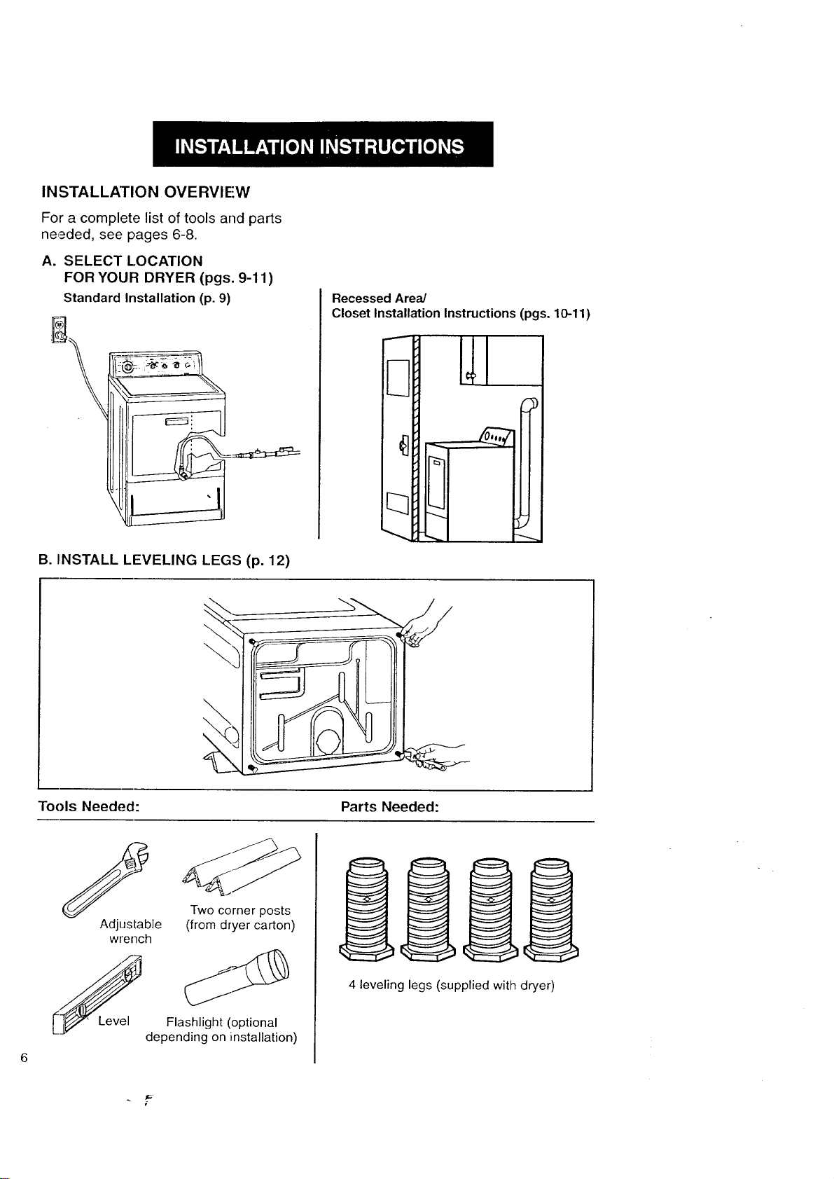
INSTALLATION OVERVIEW
For a complete list of tools and parts
needed, see pages 6-8.
A. SELECT LOCATION
FOR YOUR DRYER (pgs. 9-11)
Standard Installation (p. 9)
B. IrNSTALL LEVELING LEGS (p. 12)
Recessed Area/
Closet Installation Instructions (pgs. 10-11)
i HI
Tools Needed: Parts Needed:
6
Adjustable
wrench
Two corner posts
(from dryer carton)
Flashlight (optional
depending on installation)
4 leveling legs (supplied with dryer)
i
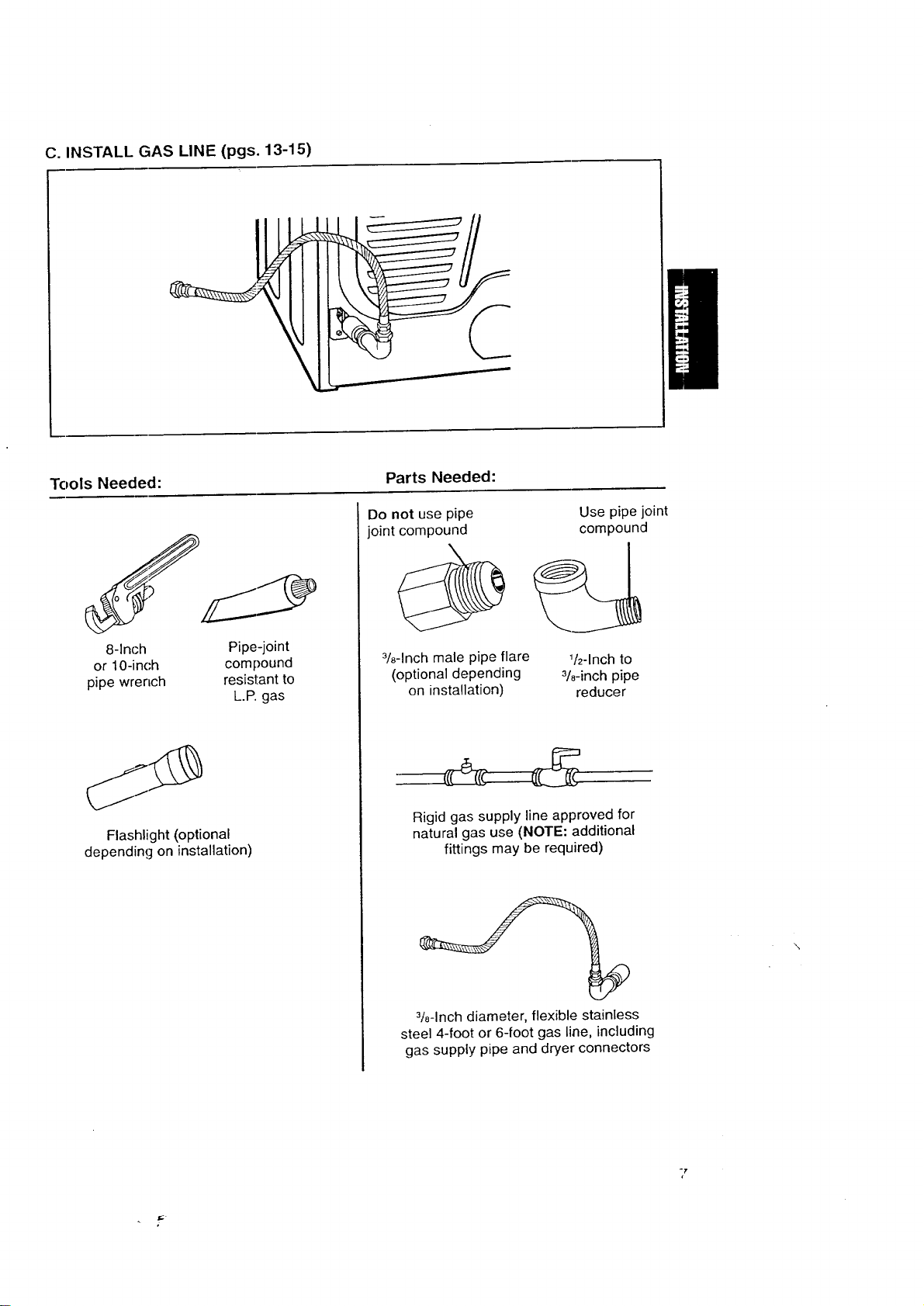
C. INSTALL GAS LINE (pgs. 13-15)
Tools Needed:
8-Inch Pipe-joint
or 10-inch compound
pipe wrench resistant to
L.P. gas
Flashlight (optional
depending on installation)
Parts Needed:
Do not use pipe
joint compound
3/8-Inch male pipe flare
(optional depending
on installation)
Use pipe joint
compound
1/2-Inch to
3/8-inch pipe
reducer
Rigid gas supply line approved for
natural gas use (NOTE: additional
fittings may be required)
3/8-Inch diameter, flexible stainless
steel 4-foot or 6-foot gas line, including
gas supply pipe and dryer connectors
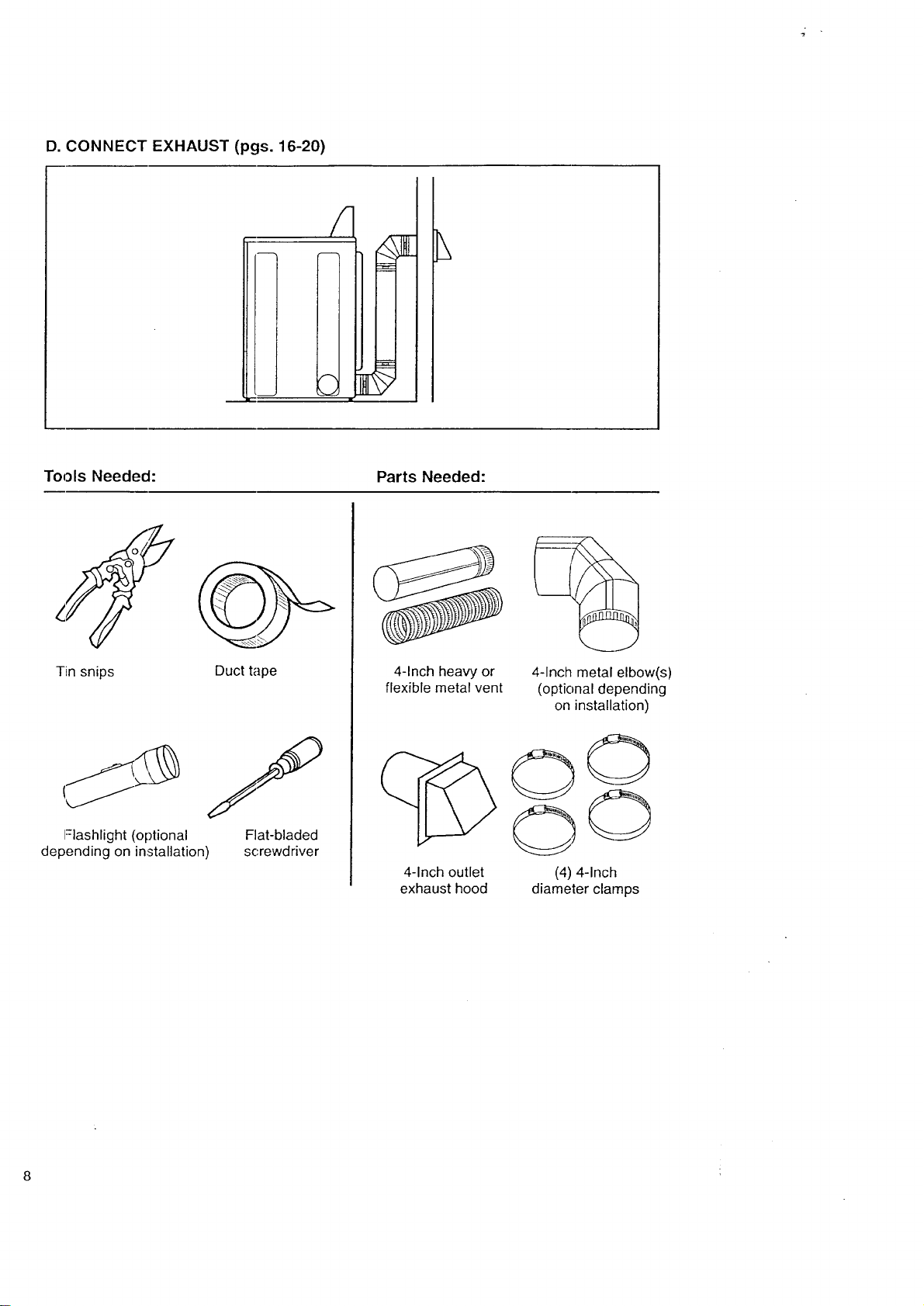
D. CONNECT EXHAUST (pgs. 16-20)
fm
Tools Needed:
Parts Needed:
Tin snips Duct tape
I-lashlight (optional
depending on installation)
Flat-bladed
screwdriver
4-Inch heavy or
flexible metal vent
4-Inch outlet
exhaust hood
4-Inch metal elbow(s)
(optional depending
on installation)
O0
O0
(4) 4-Inch
diameter clamps
8
A. SELECT LOCATION FOR
YOUR DRYER
Selecting the proper location for your
dryer makes installation easier and
gives you the best drying performance.
S']r'ANDARD INSTALLATION
Check location where dryer will be installed.
Proper installation is your responsibility.
Make sure you have everything necessary
for correct installation including proper
floor support, a level floor, a rigid gas
supply line approved for natural gas use,
and a shut-off valve.
• The dryer rnust not be installed where it
will be exposed to water and/or weather.
Proper operation of dryer cycles requires
temperatures above 45°R At lower tem-
i:,eratures, the dryer may not shut off at
the end of automatic cycles. Drying times
will be extended.
• Use, at least, the minimum installation
spacings described on page 10. This will
ensure you lqave an adequate clearance
for service and proper operation including
flow of combustion and ventilation air,
and that you have a sufficient distance
from combustible constructien.
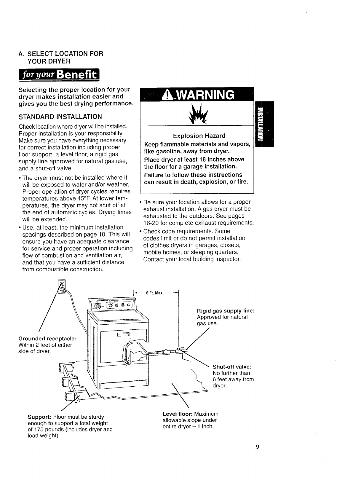
Explosion Hazard
Keep flammable materials and vapors,
like gasoline, away from dryer.
Place dryer at least 18 inches above
the floor for a garage installation.
Failure to follow these instructions
can result in death, explosion, or fire.
• Be sure your location allows for a proper
exhaust installation. A gas dryer must be
exhausted to the outdoors. See pages
16-20 for complete exhaust requirements.
• Check code requirements. Some
codes limit or do not permit installation
of clothes dryers in garages, closets,
mobile homes, or sleeping quarters.
Contact your local building inspector.
_'---- 6 Ft. Max._
Rigid gas supply line:
Approved for natural
gas use.
Grounded receptacle:
Within 2 feet of either
side of dryer.
Shut-off valve:
No further than
6 feet away from
dryer.
Support: Floor must be sturdy
enough to support a total weight
of 175 pounds (includes dryer and
load weight).
Level floor: Maximum
allowable slope under
entire dryer- 1 inch.
RE"CESSED AREA/CLOSET
INSTALLATION INSTRUCTIONS
Check governing codes and ordinances.
This dryer may be installed in a recessed
area or closet.
NOTE: No fuel burning appliances may be
installed in the same closet as a dryer.
• The dryer must not be installed where it
will be exposed to water and/or weather.
Proper operation of dryer cycles requires
temperatures above 45°E At lower tem-
peratures, the dryer may not shut off at
the end of automatic cycles. Drying times
will be extenaed.
• Use, at least, the minimum installation
spacings described below. This will
ensure you have an adequate clearance
for service and proper operation including
flow of combustion and ventilation air,
and that you have a sufficient distance
from combustible construction.
• Be sure your location allows for a proper
exhaust installation. A gas dryer must be
e}'hausted to [he outdoors. See pages
16-20 for complete exhaust requirements.
• Clqeck code requirements. Some
codes limit or do not permit installation
of clothes dryers in garages, closets,
mobile homes, or sleeping quarters.
Contact your local building inspector.
18"
_t_
-1.,--)_
OlO
FrontView
(Door Not Shown)
I
--'3'
J
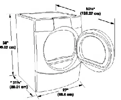
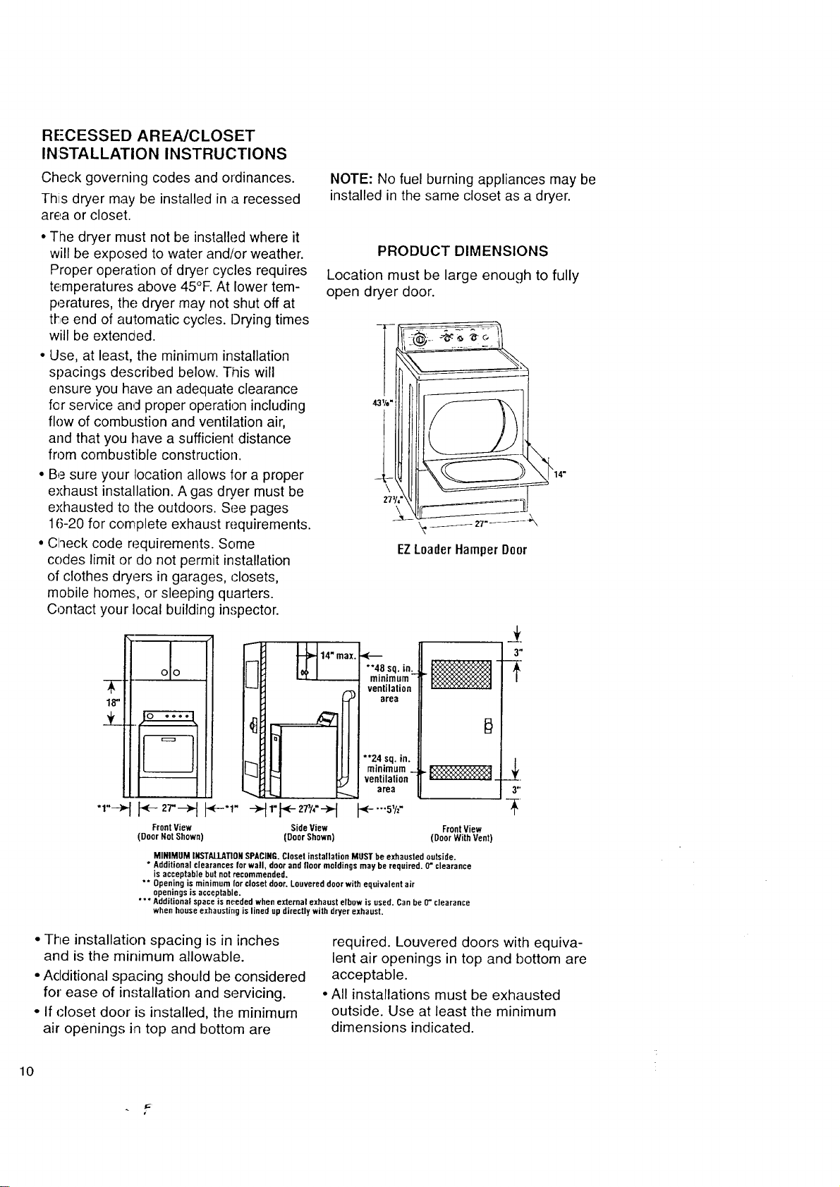
PRODUCT DIMENSIONS
Location must be large enough to fully
open dryer door.
27=],
\
kS,_27
EZLoaderHamperDoor
\14"
-_ 14" max.
_i I i
1"_ 27_14"
SideView
(DoorShown)
"'48 sq. in.
minimum -
ventilation
area
**24 sq. in.
minimum _
ventilation
area
...5_h-
3"
3 t,
Front View
(DoorWithVent)
MINIMUM INSTALLATION SPACING. Closet installation MUST be exhausted outside.
* Additional clearances for wall, door and floor moldings may be required. O"clearance
is acceptable but not recommended.
** Opening is minimum for closet door. Louvered door with equivalent air
openings is acceptable.
"** Additional space is needed when e_ernal exhaust elbow is used. Can be IT clearance
when house exhausting is lined up directly with dryer exhaust.
• The installation spacing is in inches
and is the minimum allowable.
• Additional spacing should be considered
for ease of in.,_tallation and servicing.
• If closet door is installed, the minimum
air openings in top and bottom are
required. Louvered doors with equiva-
lent air openings in top and bottom are
acceptable.
• All installations must be exhausted
outside. Use at least the minimum
dimensions indicated.
10
MOBILE HOME EXHAUST
RP'QUIREMENTS
• T[ne dryer must not be installed where it
will be exposed to water and/or weather.
Proper operation of dryer cycles requires
temperatures above 45°E At lower tem-
peratures, the dryer may not shut off at
the end of automatic cycles. Drying times
will be extended.
• Use, at least, the minimum installation
spacings described on page 10. This will
e_nsureyou have an adequate clearance
for service and proper operation includ-
irtg flow of combustion and ventilation air,
and that you have a sufficient distance
from combustible construction.
• Special provisions must be made for the
introduction of outside air into the dryer
when installed in a mobile home. The
area of any opening for the introduction
of outside air (such as a nearby window)
should be at Heasttwice as large as the
dryer exhaust opening.
This dryer is suitable for mobile home
installations. The installation must conform
to the Manufactured Home Construction
and Safety Standard, Title 24 CFR, Part
3280 (formerly the Federal Standard for
Mobile Homes Construction ,and Safety,
Title 24, HUD Part 280).
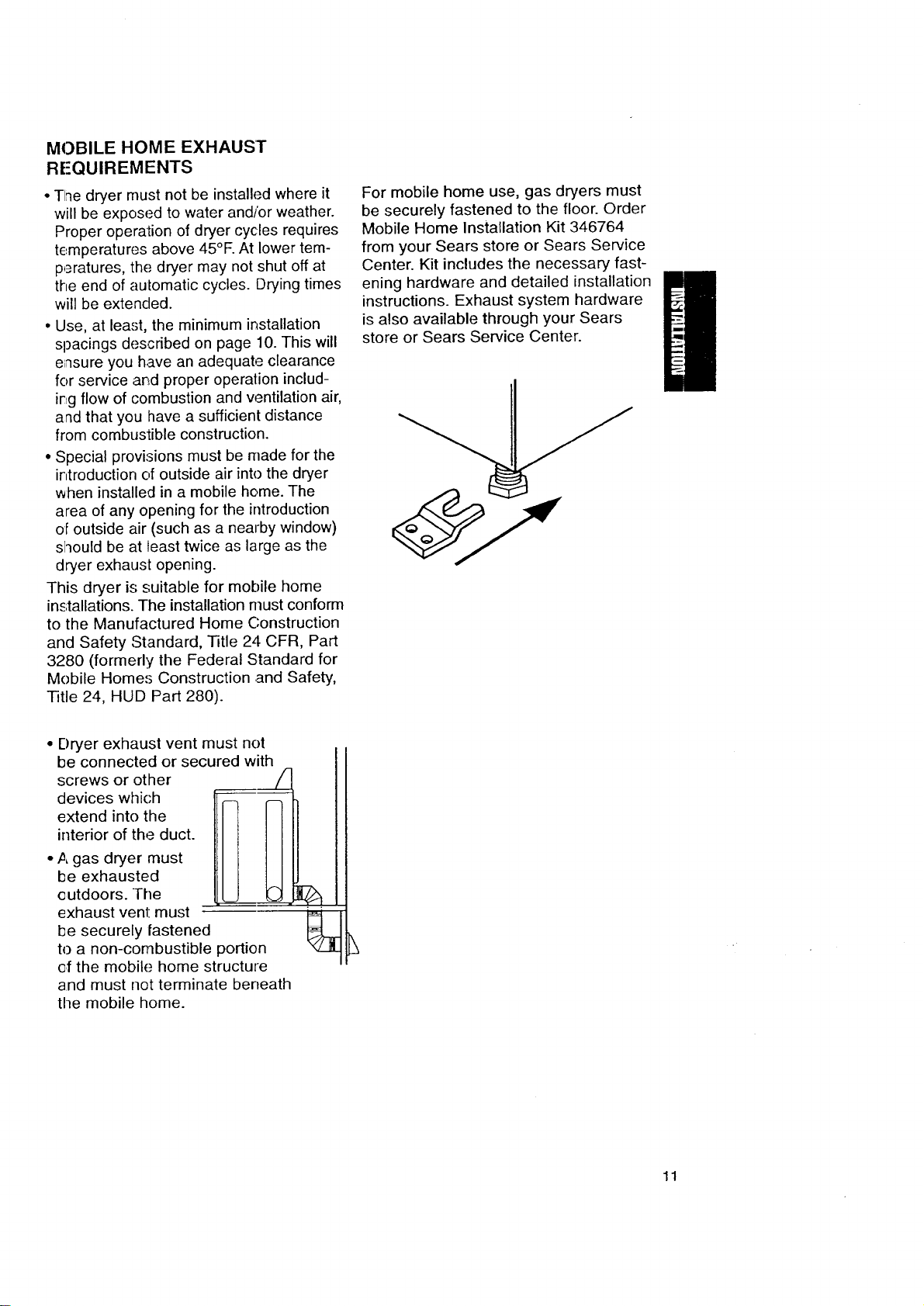
For mobile home use, gas dryers must
be securely fastened to the floor. Order
Mobile Home Installation Kit 346764
from your Sears store or Sears Service
Center. Kit includes the necessary fast-
ening hardware and detailed installation
instructions. Exhaust system hardware
is also available through your Sears
store or Sears Service Center.
• Dryer exhaust vent must not
be connected or secured with
screws or other /
devices which
extend into the _ t-
interior of the duct.
I
i
• A gas dryer must i
be exhausted t
outdoors. The _
exhaust vent must
be securely fastened
to a non-combustible portion
of the mobile home structure
and must not terminate beneath
the mobile home.
11
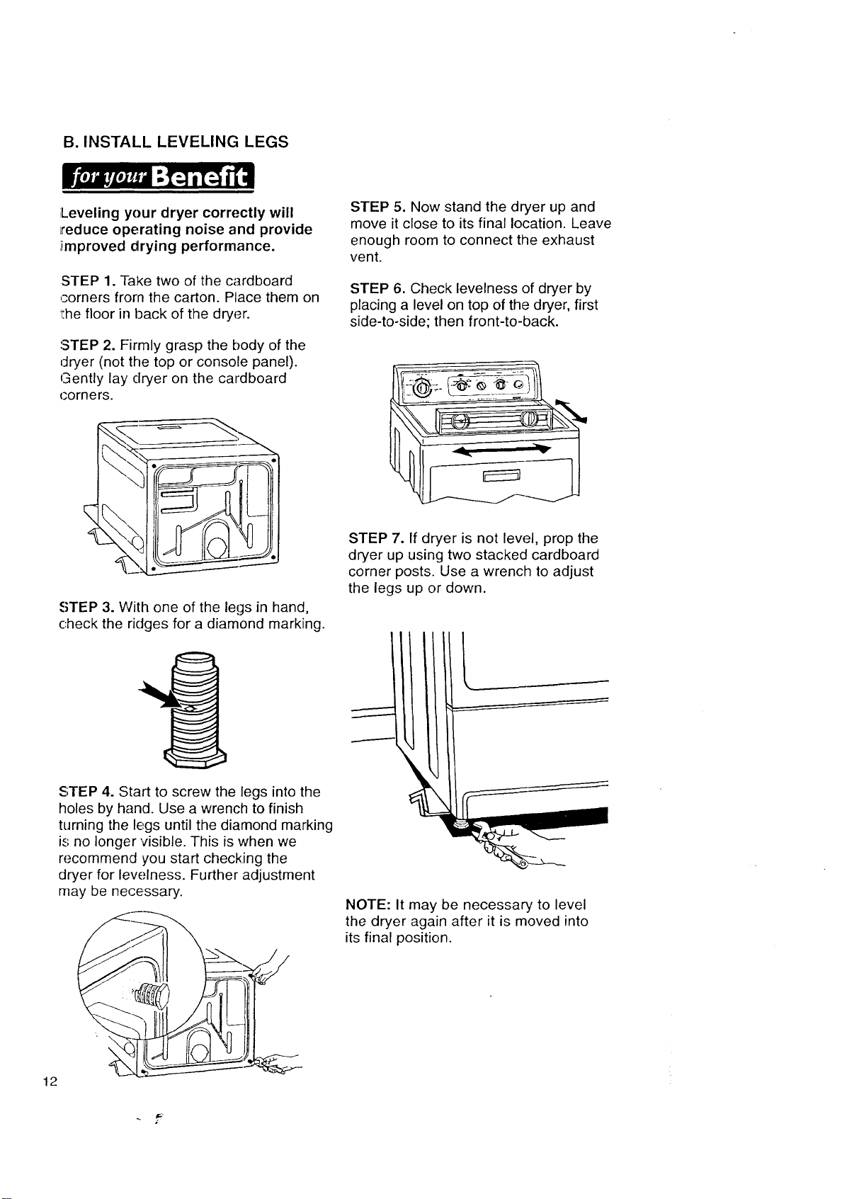
B. INSTALL LEVELING LEGS
;Leveling your dryer correctly will
1reduce operating noise and provide
iimproved drying performance.
:STEP 1. Take two of the cardboard
corners from the carton. Place them on
the floor in back of the dryer.
:STEP 2. Firmly grasp the body of the
dryer (not the top or console panel).
Gently lay clryer on the cardboard
corners.
STEP 3. With one of the legs in hand,
check the ridges for a diamond marking.
STEP 4. Start to screw the legs into the
holes by hand. Use a wrench to finish
turning the legs until the diamond marking
is no longer 'visible. This is when we
recommend you start checking the
dryer for levelness. Further adjustment
may be necessary.
\
12
STEP 5. Now stand the dryer up and
move it close to its final location. Leave
enough room to connect the exhaust
vent.
STEP 6. Check levelness of dryer by
placing a level on top of the dryer, first
side-to-side; then front-to-back.
STEP 7. If dryer is not level, prop the
dryer up using two stacked cardboard
corner posts. Use a wrench to adjust
the legs up or down.
NOTE: It may be necessary to level
the dryer again after it is moved into
its final position.
Y

C. INSTALL GAS LINE
i ,
The, proper gas connection ensures
a safe installation that meets local
code requirements.
GAS REQUIREMENTS
Explosion Hazard
Connect dryer to a regulated gas
supply.
L.P. gas supply pressure must not
exceed 13" water column.
Failure to follow these instructions
can result in death, explosion, or fire.
It is your responsibility to contact a
qualified gas line installer to ensure
you have natural gas.
• The design of this dryer has been certi-
fied by the American Gas A.,;sociation
for use at altitudes up to 10,000 feet
above sea level at the B.T.U. rating
indicated on the model/serial number
plate. Burner input adjustments are not
required when the dryer is operated
up to this level.
• When installed above 10,000 feet,
a four percent (4%) reduction of the
burner B.T.U. rating shown on the
model/serial number plate is required
for each 1,000 foot increase in eleva-
tion. For assistance when converting
to other gas types and/or installing
above 10,000 feet elevation contact
your local service company.
• Make certain your dryer has the
correct burner for the type of gas
in your home. Burner information
is located on the rating plate in
the door well of your dryer. If this
information does not agree with the
type of gas available, contact your
local Sears store or Sears Service
Center. Any change to the burner
must be made by a qualified installer.
• Provide a rigid gas supply line of
l/z-inch pipe to your dryer.
• If you are using natural gas, do not
use copper tubing.
• If your dryer has been converted to
use L.P. gas, 3/8-inch L.P.-compatible
copper tubing may be used. If the
total length of the supply line is more
than 20 feet, use larger pipe. Pipe
joint compounds that resist the action
of L.P. gas must be used. Do not use
Teflon tape.
l/z-inchgasthreaded
supply line
3/8-inchmale
threadedpipe
13
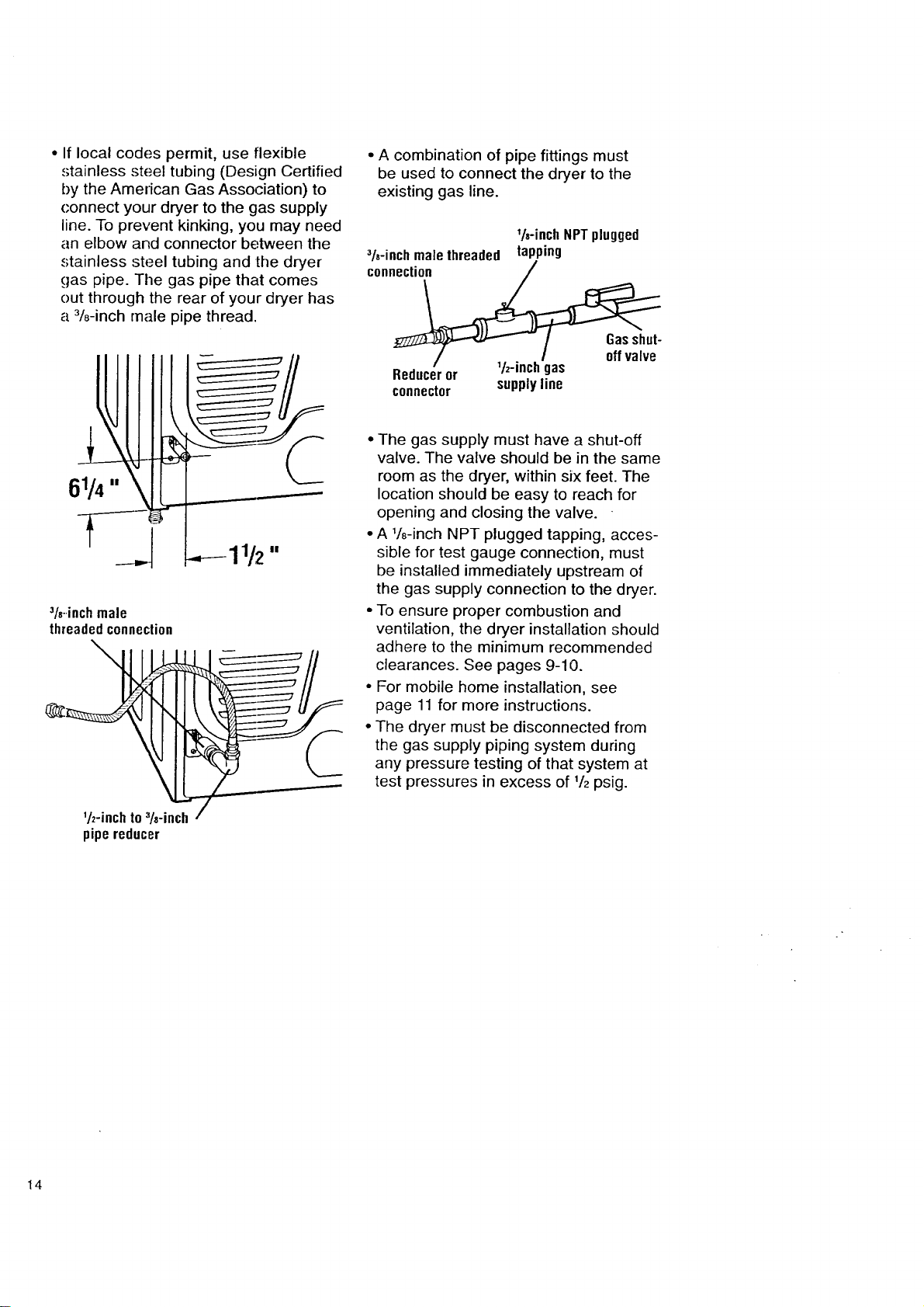
• If local codes permit, use flexible
stainless steel tubing (Design Certified
by the American Gas Association) to
(-onnect your dryer to the gas supply
line. To prevent kinking, you may need
an elbow and connector between the
stainless steel tubing and the dryer
gas pipe. The gas pipe that comes
out through the rear of your dryer has
a 3/8-inch male pipe thread.
_/8-.inchmale
threadedconnection
\
1/2-inchto3/8-inch
pipereducer
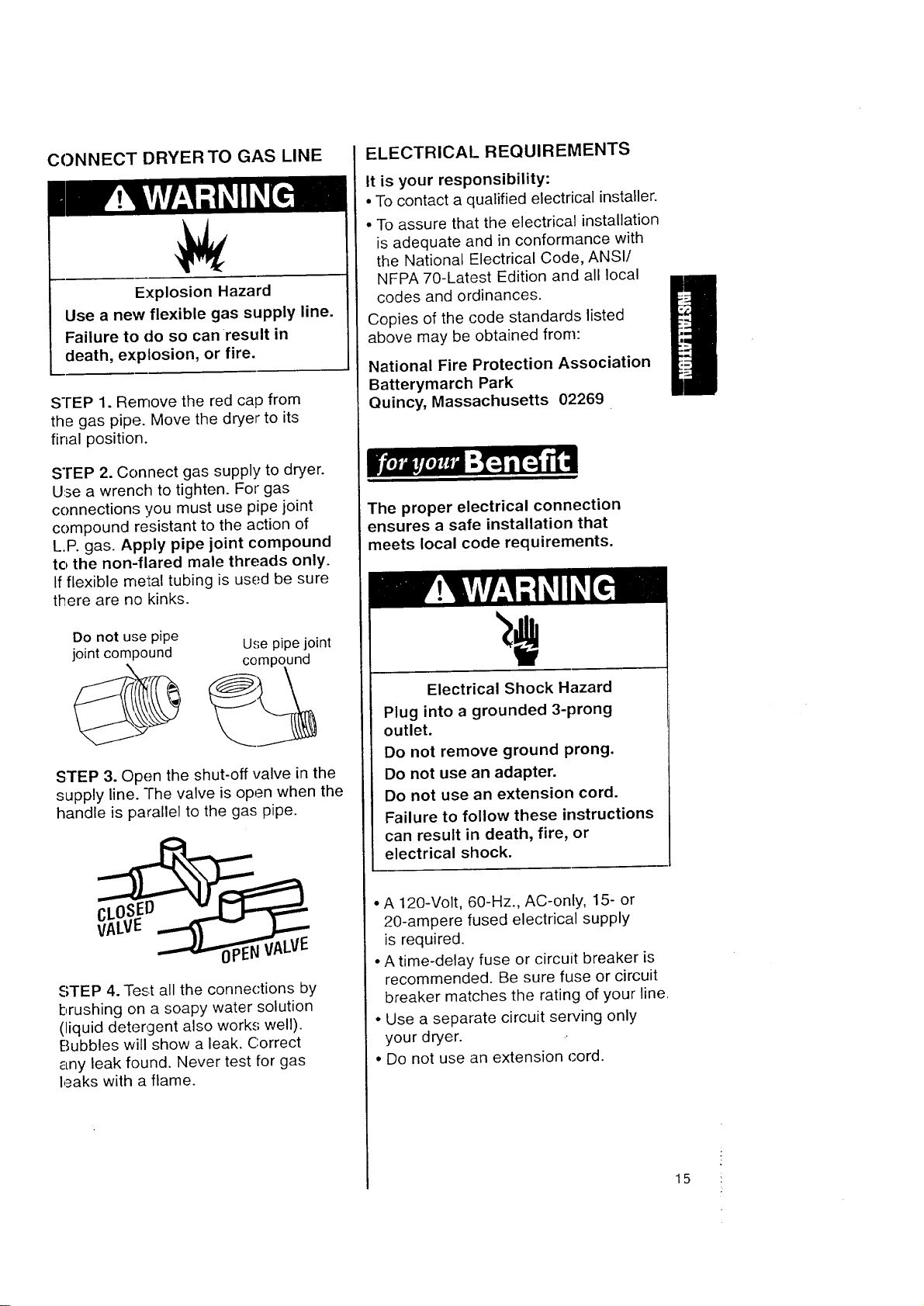
• A combination of pipe fittings must
be used to connect the dryer to the
existing gas line.
l/a-inch NPT plugged
3/a-inchmale threaded tapping
connection
%-inchgas
Reduceror
connector supplyline
Gasshut-
offvalve
• The gas supply must have a shut-off
valve. The valve should be in the same
room as the dryer, within six feet. The
location should be easy to reach for
opening and closing the valve.
• A %-inch NPT plugged tapping, acces-
sible for test gauge connection, must
be installed immediately upstream of
the gas supply connection to the dryer.
• To ensure proper combustion and
ventilation, the dryer installation should
adhere to the minimum recommended
clearances. See pages 9-10.
• For mobile home installation, see
page 11 for more instructions.
• The dryer must be disconnected from
the gas supply piping system during
any pressure testing of that system at
test pressures in excess of 1/2psig.
14
CONNECT DRYER TO GAS LINE
Explosion Hazard
Use a new flexible gas supply line.
Failure to do so can result in
death, explosion, or fire.
STEP 1. Remove the red cap from
the gas pipe. Move the dryer to its
final position.
STEP 2. Connect gas supply to dryer.
Use a wrench to tighten. For gas
connections you must use pipe joint
compound resistant to the action of
L.P. gas. Apply pipe joint compound
to the non-flared male threads only.
If flexible metal tubing is used be sure
there are no kinks.
Do not use pipe
joint compound
Use pipe joint
compound
STEP 3. Open the shut-off valve in the
supply line. The valve is open when the
handle is parallel to the gas pipe.
vALVE
STEP 4. Test all the connections by
brushing on a soapy water solution
(liquid detergent also works well).
Bubbles will show a leak. Correct
any leak found. Never test for gas
leaks with a flame.
ELECTRICAL REQUIREMENTS
It is your responsibility:
•To contact a qualified electrical installer.
• To assure that the electrical installation
is adequate and in conformance with
the National Electrical Code, ANSI/
NFPA 70-Latest Edition and all local
codes and ordinances.
Copies of the code standards listed
above may be obtained from:
National Fire Protection Association
Batterymarch Park
Quincy, Massachusetts 02269
The proper electrical connection
ensures a safe installation that
meets local code requirements.
Electrical Shock Hazard
Plug into a grounded 3-prong
outlet.
Do not remove ground prong.
Do not use an adapter.
Do not use an extension cord.
Failure to follow these instructions
can result in death, fire, or
electrical shock.
oA 120-Volt, 60-Hz., AC-only, 15- or
20-ampere fused electrical supply
is required.
• A time-delay fuse or circuit breaker is
recommended. Be sure fuse or circuit
breaker matches the rating of your line
• Use a separate circuit serving only
your dryer.
• Do not use an extension cord.
15
16
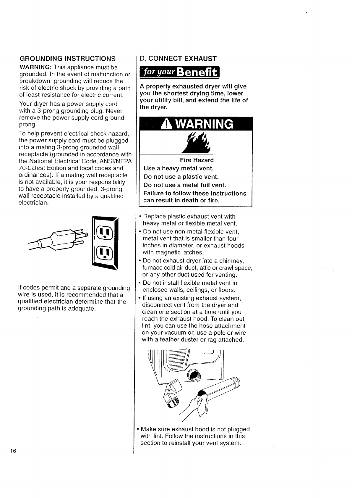
GROUNDING INSTRUCTIONS
WARNING: -[his appliance must be
grounded. In the event of malfunction or
breakdown, grounding will reduce the
risk of electric- shock by providing a path
of least resistance for electric current.
Your dryer has a power supply cord
with a 3-prong grounding plug. Never
remove the power supply cord ground
prong.
To help prevent electrical shock hazard,
the power supply cord must be plugged
into a mating 3-prong grounded wall
receptacle (grounded in accordance with
the National Flectrical Code, ANSI/NFPA
70-Latest Edition and local codes and
ordinances). If a mating wall receptacle
is not available, it is your responsibility
to have a properly grounded, 3-prong
wall receptacle installed by a_qualified
electrician.
If ('odes permit and a separate grounding
wire is used, it is recommended that a
qualified electrician determine that the
grounding path is adequate.
D. CONNECT EXHAUST
A properly exhausted dryer will give
you the shortest drying time, lower
your utility bill, and extend the life of
the dryer.
Fire Hazard
Use a heavy metal vent.
Do not use a plastic vent.
Do not use a metal foil vent.
Failure to follow these instructions
can result in death or fire.
• Replace plastic exhaust vent with
heavy metal or flexible metal vent.
• Do not use non-metal flexible vent,
metal vent that is smaller than four
inches in diameter, or exhaust hoods
with magnetic latches.
• Do not exhaust dryer into a chimney,
furnace cold air duct, attic or crawl space,
or any other duct used for venting.
° Do not install flexible metal vent in
enclosed walls, ceilings, or floors.
• If using an existing exhaust system,
disconnect vent from the dryer and
clean one section at a time until you
reach the exhaust hood. To clean out
lint, you can use the hose attachment
on your vacuum or, use a pole or wire
with a feather duster or rag attached.
• Make sure exhaust hood is not plugged
with lint. Follow the instructions in this
section to reinstall your venl system.
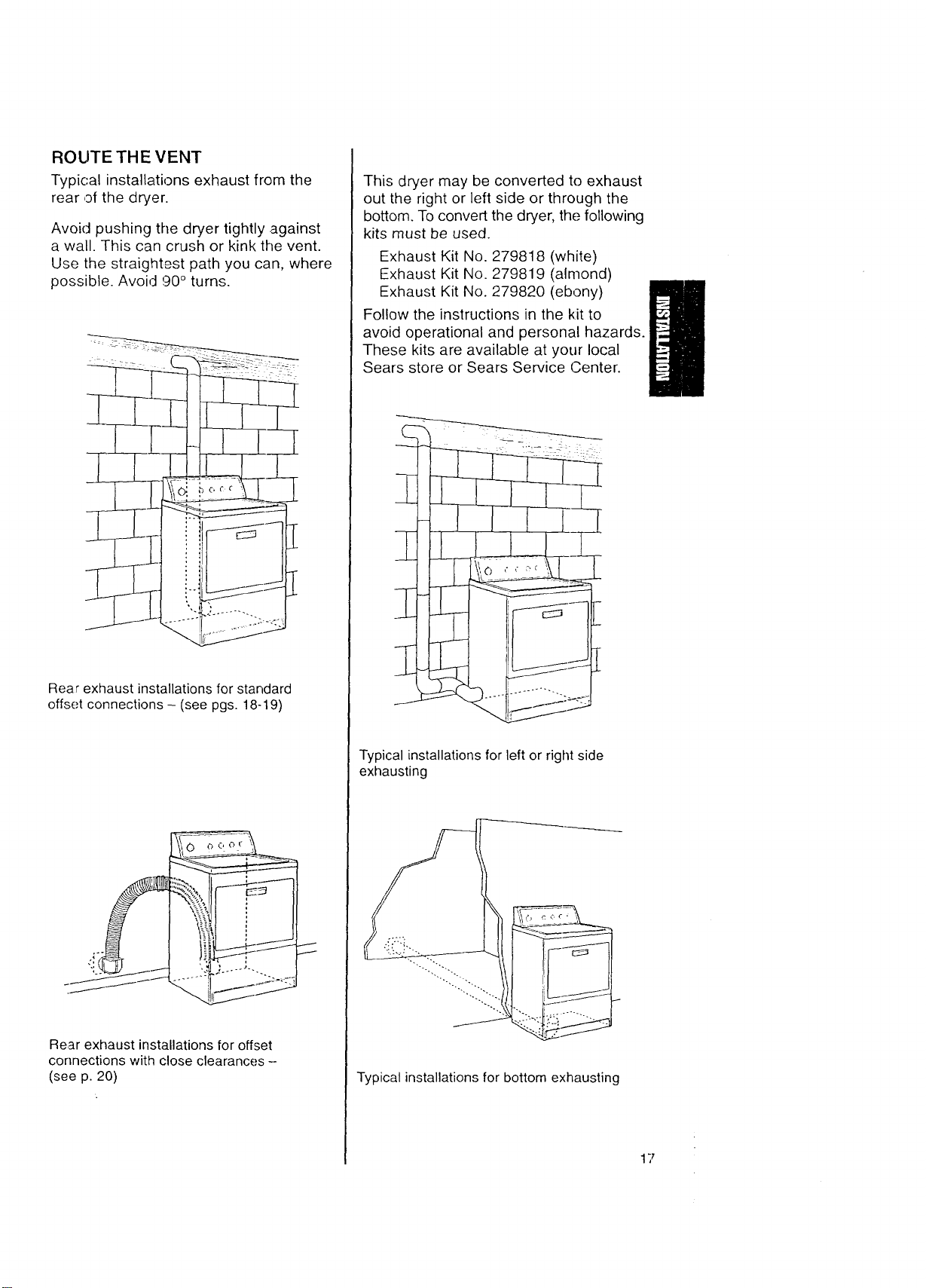
ROUTE THE VENT
Typical installations exhaust from the
rear of the dryer.
Avoid pushing the dryer tightly .against
a wall. This can crush or kink the vent.
Use the straightest path you can, where
possible. Avoid 90 ° turns.
Rear exhaust installations for standard
offset connections - (see pgs. 18-19)
Rear exhaust installations for offset
connections with close clearances -
(see p. 20)
This dryer may be converted to exhaust
out the right or left side or through the
bottom. To convert the dryer, the following
kits must be used.
Exhaust Kit No. 279818 (white)
Exhaust Kit No. 279819 (almond)
Exhaust Kit No. 279820 (ebony)
Follow the instructions in the kit to
avoid operational and personal hazards.
These kits are available at your local
Sears store or Sears Service (_Center.
Typical installations for left or right side
exhausting
Typical installations for bottom exhausting
17
18
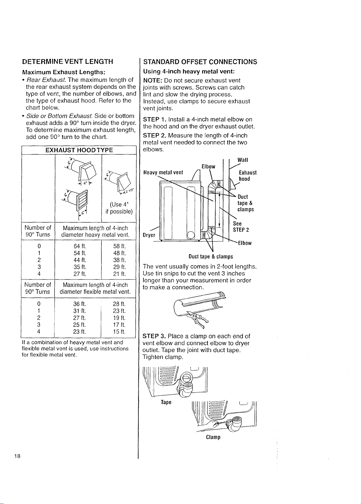
DETERMINE VENT LENGTH
Maximum Exhaust Lengths:
• Rear Exhaust. The maximum length of
the rear exhaust system depends on the
type of vent, the number of elbows, and
the type of exhaust hood. Refer to the
chart below.
• Side or Bottom Exhaust. Side or bottom
exhaust adds a 90° turn inside the dryer.
To determine maximum exhaust length,
add one 90 ° turn to the chart.
EXHAUST HOOD TYPE
(Use 4"
if possible)
Number of Maximum length of 4-inch
90° Turns diameter heavy metal vent.
0
1
2
3
4
64 ft. 58 ft.
54 ft. 48 ft.
44 ft. 38 ft.
35 ft. 29 ft.
27 ft. 21 ft.
Number of Maximum length of 4-inch
cpo°Turns diameter flexible metal vent.
0 36 ft.
1 31 ft.
2 27 ft.
3 _ 25 ft.
4 23 ft.
!
If a combination of heavy metal vent and
flexible metal want is used, use instructions
for flexible metal vent.
28 ft.
23 ft.
19 ft.
17 ft.
15 ft.
STANDARD OFFSET CONNECTIONS
Using 4-inch heavy metal vent:
NOTE: Do not secure exhaust vent
joints with screws. Screws can catch
lint and slow the drying process.
Instead, use clamps to secure exhaust
vent joints.
STEP 1. Install a 4-inch metal elbow on
the hood and on the dryer exhaust outlet.
STEP 2. Measure the length of 4-inch
metal vent needed to connect the two
elbows.
Heavy.._al vent
I
/
Dryer
Elbow
Wall
/
Exhaust
hood
x
\_' Duct
tape&
clamps
See
STEP2
_Elbow
Ducttape& clamps
The vent usually comes in 2..foot lengths.
Use tin snips to cut the vent 3 inches
longer than your measurement in order
to make a connection.
STEP 3. Place a clamp on each end of
vent elbow and connect elbow to dryer
outlet. Tape the joint with duct tape.
Tighten clamp.
Tape
Clamp
STEP4.Connectheavymetalventto
elbow.Tapethejointwithducttape.
Tightenclamp.
STEP5.Installoneendofelbowon
heavymetalvent,theotherendtothe
exhausthood.Tapejointsandtighten
clamps.
FinishInstallation,See"REVIEW
INSTALLATION"on page21.
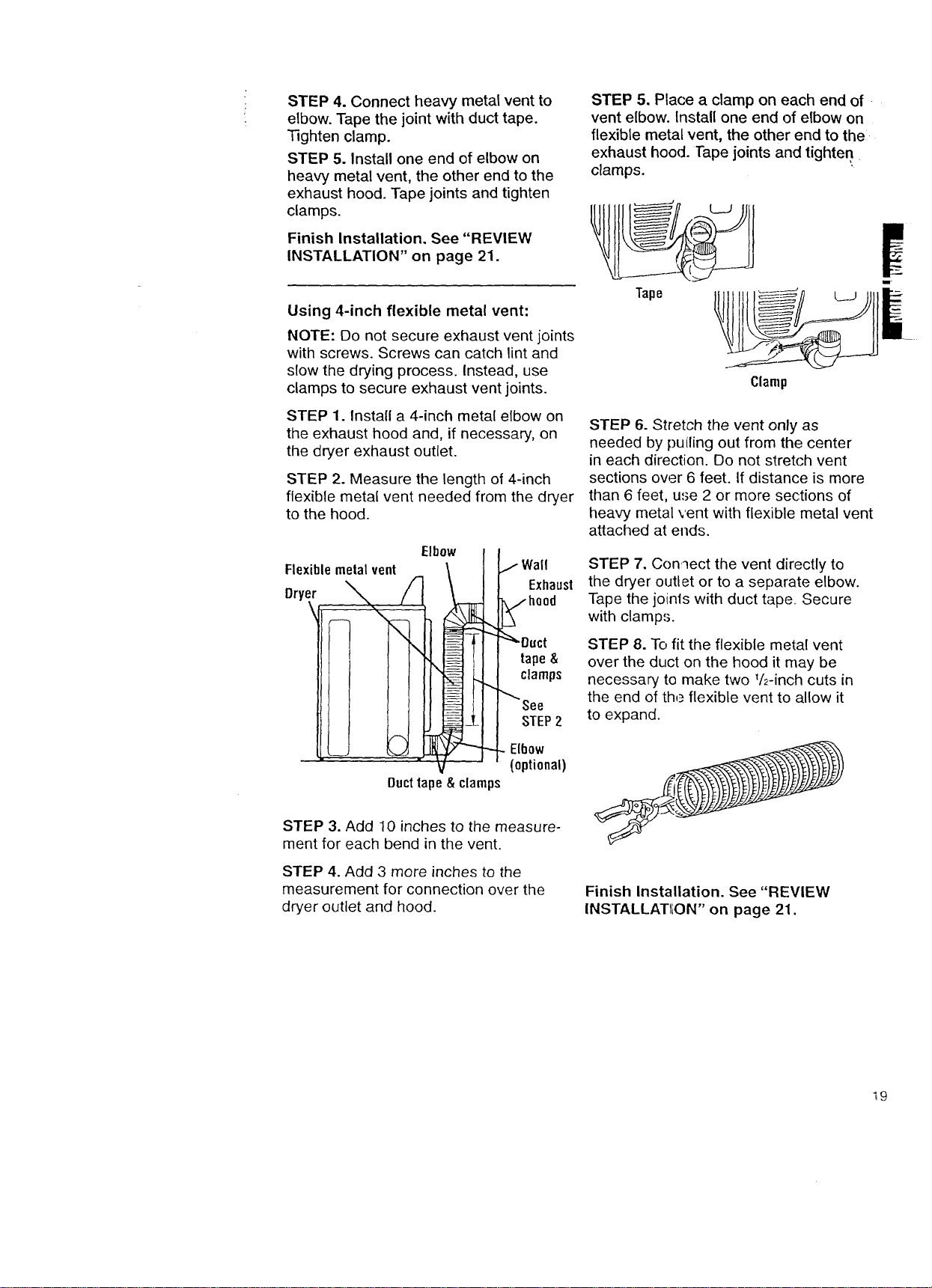
Using4-inch flexible metal vent:
NOTE: Do not secure exhaust vent joints
with screws. Screws can catch lint and
slow the drying process. Instead, use
clamps to secure exhaust vent joints.
STEP 1. Install a 4-inch metal elbow on
the exhaust hood and, if necessary, on
the dryer exhaust outlet.
STEP 2. Measure the length of 4-inch
flexible metal vent needed from the dryer
to the hood.
Elbow I I
Flexiblemetal vent \ I I1/Wall
_ \ /-1 \ I / Exhaust
I1( i I "1_,11N f l I-'_"uct
III I I I "#.Hill tape&
I r IIN
III t ! tll I_ILI I See
_ t Elbow
" " V ' ' (optional)
Ducttape & clamps
STEP 3. Add 10 inches to the measure-
ment for each bend in the vent.
STEP 4. Add 3 more inches to the
measurement for connection over the
dryer outlet and hood.
STEP 5. Place a clamp on each end of
vent elbow. Install one end of elbow on
flexible metal vent, the other end to the
exhaust hood. ]'ape joints and tighten
clamps.
Clamp
STEP 6. Stretch the vent only as
needed by puiling out from the center
in each direction. Do not stretch vent
sections over 6 feet. If distance is more
than 6 feet, use 2 or more sections of
heavy metal vent with flexible metal vent
attached at ends.
STEP 7, Connect the vent directly to
the dryer outlet or to a separate elbow.
Tape the joinls with duct tape., Secure
with clamp,';.
STEP 8. To fit the flexible metal vent
over the duct on the hood it may be
necessary to make two %-inch cuts in
the end of the flexible vent to allow it
to expand.
Finish Installation. See "REVIEW
INSTALLATliON" on page 21.
19
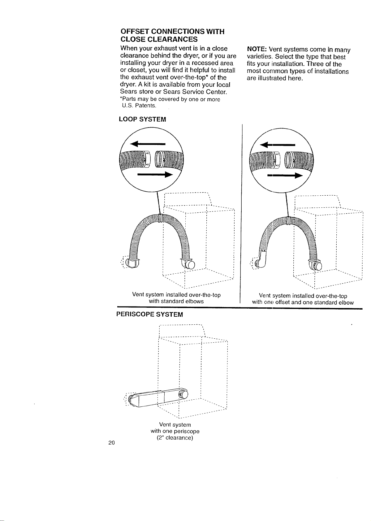
OFFSET CONNECTIONS WITH
CLOSE CLEARANCES
When your exhaust vent is in a close
clearance behind the dryer, or if you are
installing your dryer in a recessed area
or closet, you will find it helpful to install
the exhaust vent over-the-top* of the
dryer. A kit is available from your local
Sears store or Sears Service Center.
*Parts may be covered by one or more
U.S. Patents.
LOOP SYSTEM
NOTE: Vent systems come in many
varieties. Select the type that best
fits your installation. Three of the
most common types of installations
are illustrated here.
Vent system installed over-the-top
with standard elbows
Vent system installed over-the-top
with one offset and one standard elbow
PERISCOPE SYSTEM
2O
Vent system
with one periscope
(2" clearance)
REVIEW INSTALEATION
Take a few minutes to complete
this checklist£1t will help assure you
that you have a proper installation
and will increase your satisfaction
with your Kenmore dryer.
[] Check that all parts you removed
from the parts packages are now
installed.
[] Ensure that dryer is positioned in
its final location. Make sure vent is
not crushed or kinked.
[] Ensure that dryer is level by placing
a level on top of the dryer, first side-
to-side; then front-to-back. If dryer is
not level, adjust the legs up or down.
[] Check to make sure you have all
the tools you started with.
I
FINAL STEPS
[] Plug the power supply cord into
the grounded outlet or power supply.
[] Turn power supply on.
[] Wipe the interior of the drum
thoroughly with a damp cloth to
remove any dust.
[] Remove the blue protective film on
the console and any tape remaining
on dryer.
[]
[]
To remove air from the gas line, set
the dryer on a full heat cycle (not the
air cycle) for 20 minutes. After five
minutes, open dryer door. The burner
should have ignited during these five
minutes. If you do not feel heat, turn
the dryer off and WAIT5 MINUTES.
During these 5 minutes check to be
sure dryer gas supply valve is open.
Repeat steps above. If the burner still
does not ignite, see Troubleshooting
informaticn on pages 35-36.
Read the rest of this manual to fully
understand your new dryer.
2 ¸
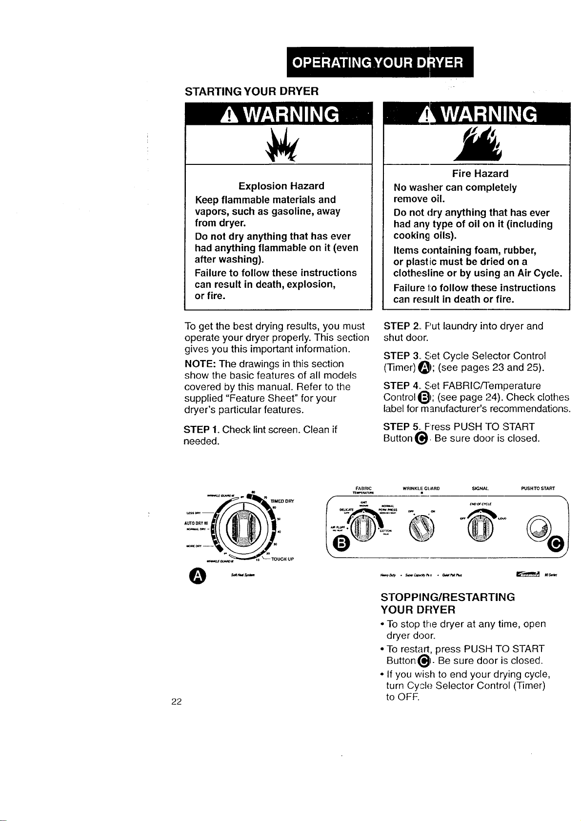
STARTING YOUR DRYER
Explosion Hazard
Keep flammable materials and
vapors, such as gasoline, away
from dryer.
Do not dry anything that has ever
had anything flammable on it (even
after washing).
Failure to follow these instructions
can result in death, explosion,
or fire.
Fire Hazard
No washer can completely
remove oil.
Do not dry anything that has ever
had any type of oil on it (including
cooking oils).
Items containing foam, rubber,
or plastic must be dried on a
clothesline or by using an Air Cycle.
Failure 1:ofollow these instructions
can result in death or fire.
To get the best drying results, you must
operate your dryer properly. This section
gives you this important information.
NOTE: The drawings in this section
show the basic features of all models
covered by this manual. Refer to the
supplied "Feature Sheet" for your
dryer's particular features.
STEP 1. Check lint screen. Clean if
needed.
STEP 2, Put laundry into dryer and
shut door.
STEP 3. Set Cycle Selector Control
(-Iqmer) _l; (see pages 23 and 25).
STEP 4.. Set FABRIC/-remperature
Control _; (see page ,_4). Check clothes
label for manufacturer's recommendations.
STEP 5,, Press PUSH -ro START
Button _, Be sure
door is closed.
22
FABRIC WRINKLE GI,L_RD SIGNAL PUSH TO START
STOPPING/RESTARTING
YOUR DRYER
• To stop the dryer at any time, open
dryer door.
• To restart, press PUSH TO START
Buttoner. Be sure door is closed.
• If you wish to end your drying cycle,
turn Cycle Selector Control (Timer)
to OFF.
CYCLE DESCRIPTION
The AUTO DRY Cycle saves you time
by providing the best drying results
in the shortest time.This can help
you save money on utility bills and
reduce the risk of fabric damage.
AUTO DRY CYCLE
Use this cycle for most loads. Drying
time varies according to type of fabric,
size of load, and dryness setting.
• Set the Cycle Selector Control (Timer)
to NORMAL DRY(*) which is good for
most fabrics.
• At the end of the cycle, feel the dried
clothes. If they are damp, select MORE
DRY the next time you do a similar load.
If they are overdried, select LESS DRY
the next time you do a similar load.
• Dryness is determined by an electronic
sensor that "feels" the amount of mois-
ture in clothes as they pass over it. When
the dryness selected is reached, the
dryer goes into a 10-minute (approx.)
COOL DOWN period.
• The End-of-Cycle SIGNAL sounds (if
selected) once the cycle is completed.
• If you do not unload the dryer, it goes
into WRINKLE GUARD automatically.
For an explanation of WRINKLE
GUARD, see page 27.
NOTE: On some models, WRINKLE
GUARD is selected by an option switch.
TIMED DRY CYCLE
Use this cycle to get up to 70 or 80
minutes (depending on model) of
heated drying time.
• The heating cycle is followed by a 10-
minute (approx.) COOL. DOWN period.
• The End-of-Cycle SIGNAL sounds (if
selected) once the cycle is completed:
NOTE: Dryers with a WRINKLE GUARD
Option control will go into WRINKLE
GUARD immediately following this cycle
if it is selectad.
TOUCH UP CYCLE
Use this cycle to smooth synthetic and
permanent press clothes that are clean
but wrinkled from being crowded in a
closet or suitcase.
• This setting provides at)out 15 minutes
of heated tumbling followed by a 10-
minute (approx.) COOL, DOWN period.
• Remove clothes immediately when
tumbling stops.
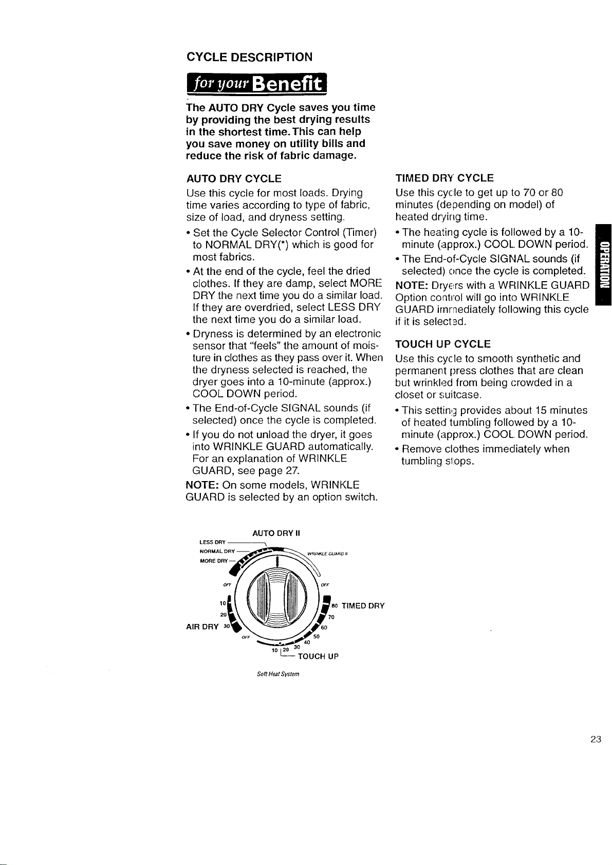
AUTO DRY II
LESS DRY --_
NORMAL DRY --
MORE
10
2O
AIR DRY
18o TIMED DRY
;0
20 30
10
L.___ TOUCH UP
Soft Heat System
23
FABRIC/TEMPERATURE CONTROL
Proper use of this control helps
ensure that fabrics are dried at the
right temperature for maximum life,.
Use this control to select the drying
temperature that matches the fabrics
in your load.
• Select LOW for delicate fabrics. Select
HIGH for durable fabrics such as sturdy
work clothes or bath towels.
• The FABRiC/Temperature Control
will not work when the Cycle Selector
Control (lqmer) is in the AIR DRY Cycle.
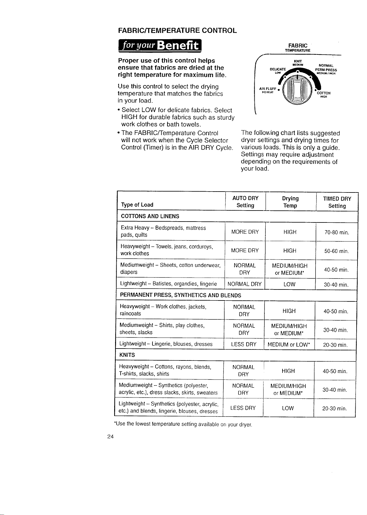
FABRIC
TEMPERATURE
F KNIT
I_mUM NORMAL
DELICATE PERM PRESS
LOW MEDIUM / H_ H
AIR FLUFF •
I_o H_AT
COTTON
The following chart lists suggested
dryer settings and drying times for
various loads. This is only a guide.
Settings may require adjustment
depending on the requirements of
your load.
Type of Load
COTTONS AND LINENS
AUTO DRY [ Drying 1. TIMED DRY
Setting Temp Setting
Extra Heavy - Bedspreads, mattress
pads, quilts
Heavyweight - Towels, jeans, corduroys,
work clothes
Mediumweight - Sheets, cotton underwear,
diapers
Lightweight- Batistes, organdies, lingerie
MORE DRY
MORE DRY
NORMAL
DRY
NORMAL DRY
PRESS, SYNTHETICS AND BLENDS
HIGH
HIGH
MEDIUM/HIGH
or MEDIUM*
LOW
70-80 min.
50-60 min.
40-50 rain.
30-40 rain.
PERMANENT
Heavyweight - Work clothes, jackets, NORMAL
HIGH 40-50 min.
raincoats DRY
Mediumweight - Shirts, play clothes, NORMAL MEDIUM/HIGH
30-40 min.
sheets, slacks DRY or MEDIUM*
Lightweight- Lingerie, blouses, dresses LESS DRY 1_4EDIUMor LOW* 20-30 rain.
KNITS
Heavyweight-Cottons, rayons, blends, NORMAL
HIGH 40-50 min.
T-shirts, slacks, shirts DRY
Mediumweight- Synthetics (polyester, NORMAL i MEDIUM/HIGH
acrylic, etc.), dress slacks, skirts, sweaters DRY i or MEDIUM* 30-40 min.
Lightweight- Synthetics (polyester, acrylic, LESS DRY I LOW 20-30 rain.etc.) and blends, lingerie, blouses, dresses
*Use the lowest temperature setting available on your dryer.
24
USING AIR DRY/AIR FLUFF
Using these cycles gives you all the
benefits of hang drying with a shorter
drying time.
Use the AIR DRY Cycle to get up to
30 minutes of drying time in room tem-
perature air. Use this setting for items
that will not tolerate heat such as plastics
and foam rubber. Also use for airing and
fluffing items such as pillows.
The AIR FLUFF Setting operates exactly
like the AIR DRY Cycle. This setting is
available on models that do not have an
AIR DRY Cycle in the Cycle Selector
Control ('lqmer).
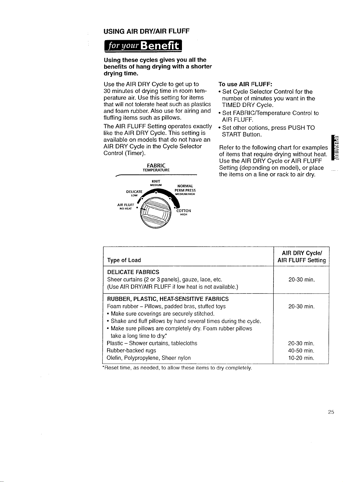
FABRIC
TEMPERATURE
KNIT
MEDIUM
NORMAL
PERM PRESS
AIR FLUFF
NO HEAT •
COI_ON
To use AIR FLUFF:
• Set Cycle Selector Control for the
number of minutes you want in the
TIMED DR'( Cycle.
• Set FABRICFI-emperature Control to
AIR FLUFF.
• Set other options, press PUSH TO
START Button.
Refer to the following chart for examples
of items that require drying without heat.
Use the AIR DRY Cycle orAIR FLUFF
Setting (depending on model), or place
the items on a line or rack to air dry.
Type of Load
DELICATE FABRICS
Sheer curtains (2 or 3 panels), gauze, lace, etc.
(Use AIR DRY/AIR FLUFF if low heat is not available.)
RUBBER, PLASTIC, HEAT-SENSITIVE FABRICS
Foam rubber - Pillows, padded bras, stuffed toys
• Make sure coverings are securely stitched.
• Shake and fluff pillows by hand several times during the cycle.
• Make sure pillows are completely dry. Foam rubber pillows
take a long time to dry.*
Plastic - Shower curtains, tablecloths
Rubber-backed rugs
Olefin, Polypropylene, Sheer nylon
*Reset time, as needed, to allow these items to dry completely.
AIR DRY Cycle/
AIR FLUFF Setting
20-30 min.
20--30min.
20-30 min.
40-50 min.
10-20 rain.
25
END-OF-CYCLE SIGNAL CONTROL
Your dryer sounds a signal when
a drying cycle is finished.The signal
is helpful when you are drying
permanent press, synthetics, and
other items. These items should be
removed from the dryer as soon as
it stops in order to prevent wrinkles.
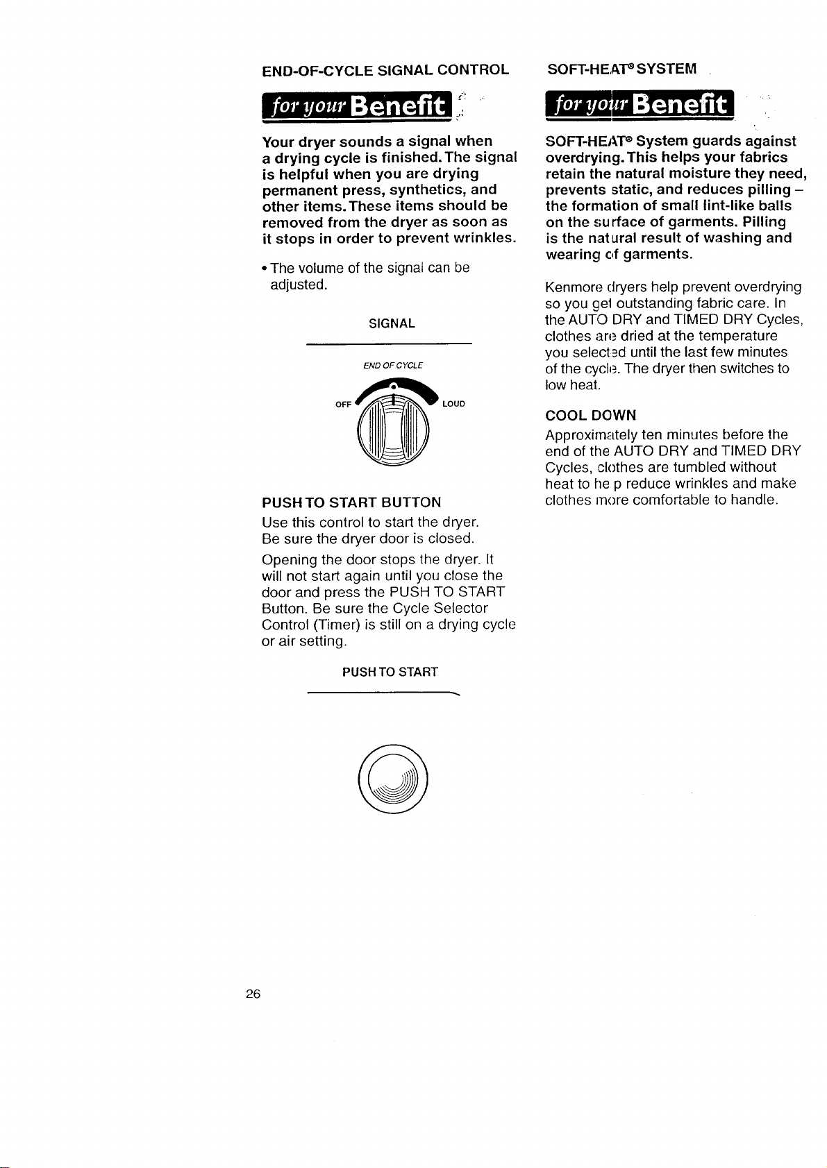
• The volume of the signal can be
adjusted.
SIGNAL
END OF CYCLE
LOUD
PUSH TO START BUTTON
Use this control to start the dryer.
Be sure the dryer door is closed.
Opening the door stops the dryer. It
will not start again until you close the
door and press the PUSH TO START
Button. Be sure the Cycle Selector
Control (Timer) is still on a drying cycle
or air setting.
PUSH TO START
SOFT-HEAT _ SYSTEM
SOFT-HEAT _ System guards against
overdrying. This helps your fabrics
retain the natural moisture they need,
prevents static, and reduces pilling -
the formation of small lint-like balls
on the surface of garments. Pilling
is the natural result of washing and
wearing of garments.
Kenmore dryers help prevent overdrying
so you gel outstanding fabric care. In
the AUTO DRY and TIMED DRY Cycles,
clothes are dried at the temperature
you select=_d until the last few minutes
of the cycle. The dryer then switches to
low heat.
COOL DOWN
Approximately ten minutes before the
end of the AUTO DRY and TIMED DRY
Cycles, clothes are tumbled without
heat to he p reduce wrinkles and make
clothes more comfortable to handle.
26
USING WRINKLE GUARD LINT ALERT
WRINKLE GUARD helps keep your
permanent press items wrinkle free
when you don't unload the dryer
promptly at the end of the AUTO DRY
Cycle.
If you do not open the door at the end
of the AUTO DRY Cycle, WRINKLE
GUARD will tumble the clothes without
heat for about 15 seconds periodically
throughout the cycle.
• On dryers with WRINKLE GUARD II,
periodic tumbling will continue for
about 40 minutes unless you open the
dryer door.
• On dryers with WRINKLE GUARD Ill,
periodic tumbling will continue for
about 21/2hours unless you open the
dryer door.
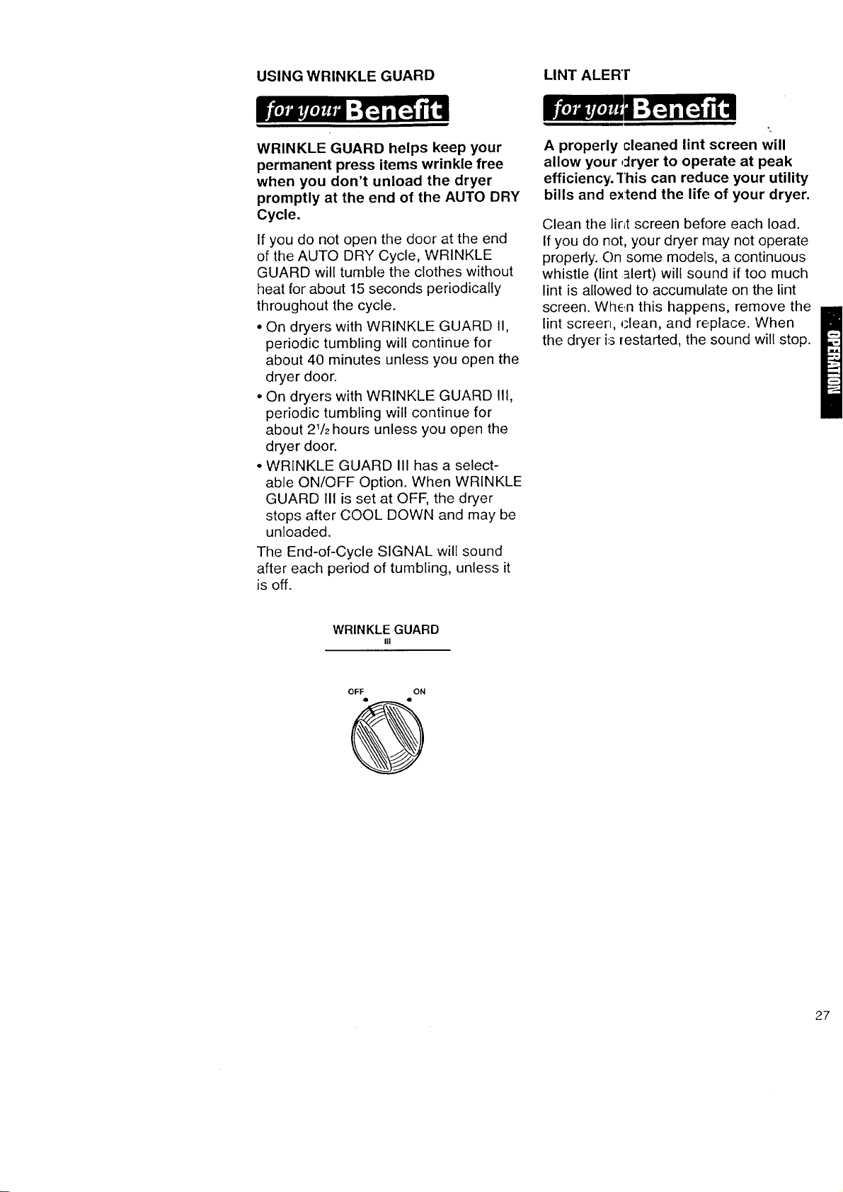
• WRINKLE GUARD III has a select-
able ON/OFF Option. When WRINKLE
GUARD III is set at OFF, the dryer
stops after COOL DOWN and may be
unloaded.
The End-of-Cycle SIGNAL will sound
after each period of tumbling, unless it
is off.
A properly cleaned lint screen will
allow your dryer to operate at peak
efficiency'. This can reduce your utility
bills and e_tend the life of your dryer.
Clean the lint screen before each load.
If you do not, your dryer may not operate
properly. (:)n some models, a continuous
whistle (lint alert) will sound if too much
lint is allowed to accumulate on the lint
screen. Whe,n this happens, remove the
lint screen, clean, and replace. When
the dryer is restarted, the sound will stop.
WRINKLE GUARD
Ul
OFF ON
27
HEATED DRY RACK
The dry rack was shipped on top
of your dryer. Remove and discard
shipping blocks before using.
Use the heated drying rack to
machine dry items you would not
necessarily want to tumble dry.
The dry rack gives you concentrated
heat for efficient and uniform drying.
It also reduces noise when drying
items that have buckles.
To Use the Heated Dry Rack:
Do not remove lint screen.
STEP 1. Open dryer door.
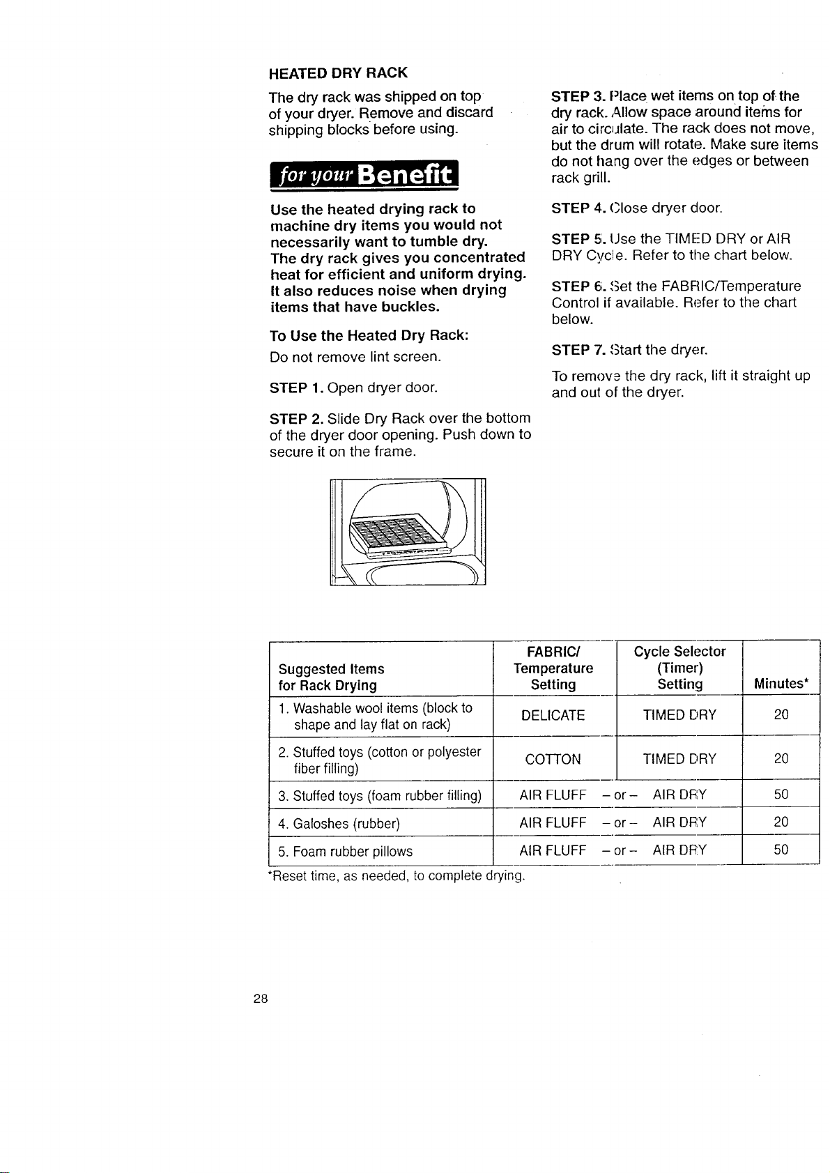
STEP 2. Slide Dry Rack over the bottom
of the dryer door opening. Push down to
secure it on the frame.
STEP 3. Place wet items on top of the
dry rack. Allow space around items for
air to circ4Jlate. The rack does not move,
but the drum will rotate. Make sure items
do not hang over the edges or between
rack grill.
STEP 4. Close dryer door.
STEP 5. Use the TIMED DRY or AIR
DRY Cycle. Refer to the chart below.
STEP 6. ,Set the FABRICfTemperature
Control if available. Refer to the chart
below.
STEP 7. ,Start the dryer.
To remow the dry rack, lift it straight up
and out of the dryer.
FABRIC/ Cycle Selector
Suggested Items Temperature (Timer)
for Rack Drying Setting Setting Minutes*
1. Washable wool items (block to
DELICATE TIMED DRY 20
shape and lay flat on rack)
2. Stuffed toys (cotton or polyester COTTON TIMED DRY 20
fiber filling)
3. Stuffed toys (foam rubber filling) AIR FLUFF - or- AIR DRY 50
4. Galoshes (rubber) AIR FLUFF - or- AIR DRY 20
5. Foam rubber pillows AIR FLUFF - or- AIR DRY 50
*Reset time, as needed, to complete drying.
28
Follow these recommendations to
help save on utility bills and prolong
the life of your garments.
PREPARING CLOTHES
FOR DRYING
• Refer to your Washer Owner's Manual
for proper washing techniques and
additional laundry tips.
• See page 5 of this book for Important
Safety Instructions.
SORTING CLOTHES
CHOOSING LOAD SIZE:S
• Mix large ilerns with small items.
Load the dryer by the amount of space
items take up, not by their weight. Do
not overload lhe dryer. Overcrowding
causes uneven drying and wrinkling,
and car) cause items to wear out faster
(because of pilling).
• You may need to rearrange large items
(sheets, blankets, tablecloths) during
a cycle to reduce bailing or rolling up.
• For better tumbling action, when drying
only a few small items, add one or two
lint-free towels. This also prevents
small lightweight items from blocking
airflow.
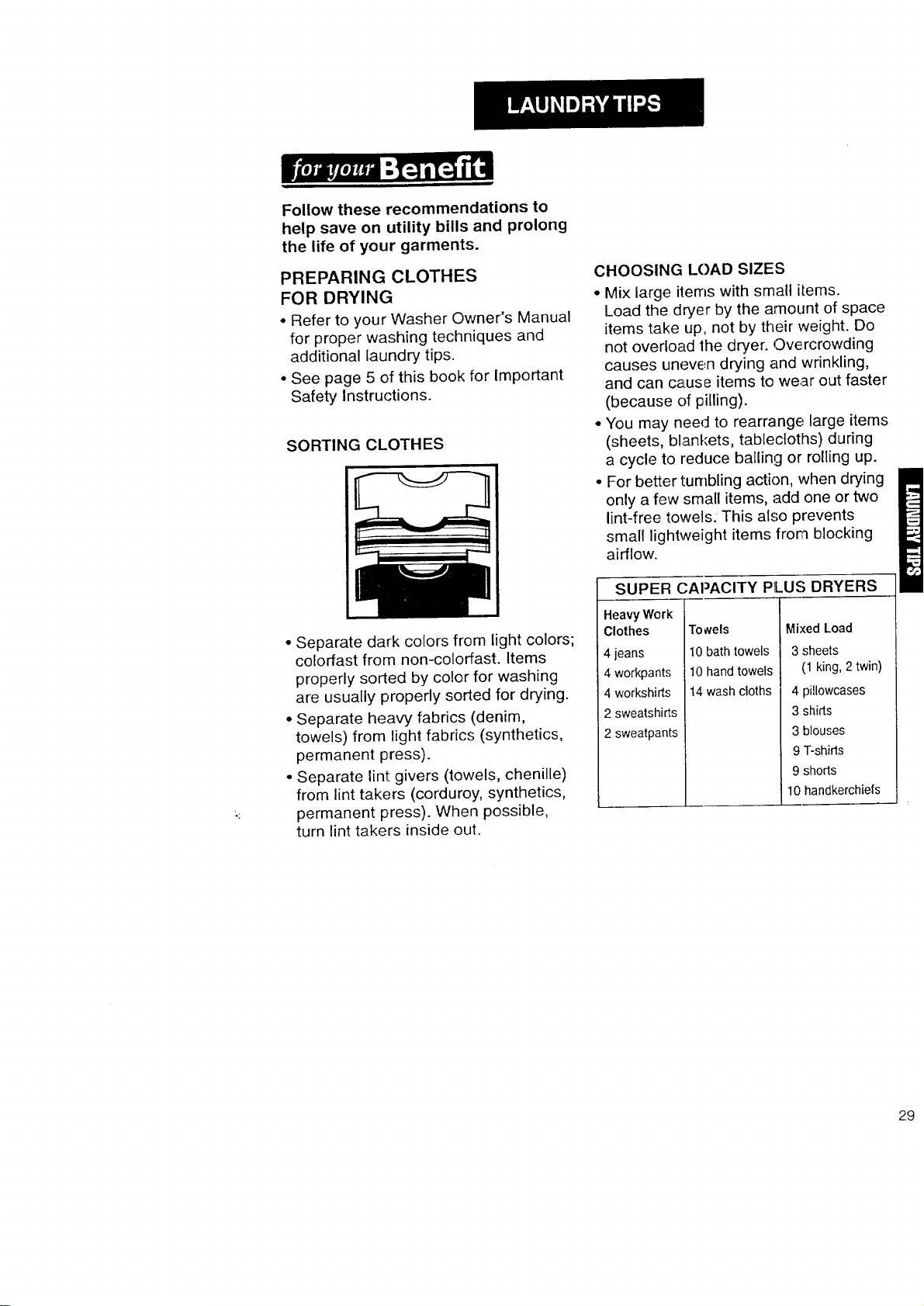
• Separate dark colors from light colors;
colorfast from non-colorfast. Items
properly sorted by color for washing
are usually properly sorted for drying.
• Separate heavy fabrics (denim,
towels) from light fabrics (synthetics,
permanent press).
• Separate lint givers (towels, chenille)
from lint takers (corduroy, synthetics,
permanent press). When possible,
turn lint takers inside out.
SUPER CAPACITY PLUS DRYERS
Heavy Work
Clothes
4 jeans
4 workpants
4 workshirts
2 sweatshirts
2 sweatpants
Towels
10 bathtowels
10 handtowels
14 wash cloths
Mixed Load
3 sheets
(1 king,2 twin)
4 pillowcases
3 shirts
3 blouses
9 T-shirts
9 shorts
10 handkerchiefs
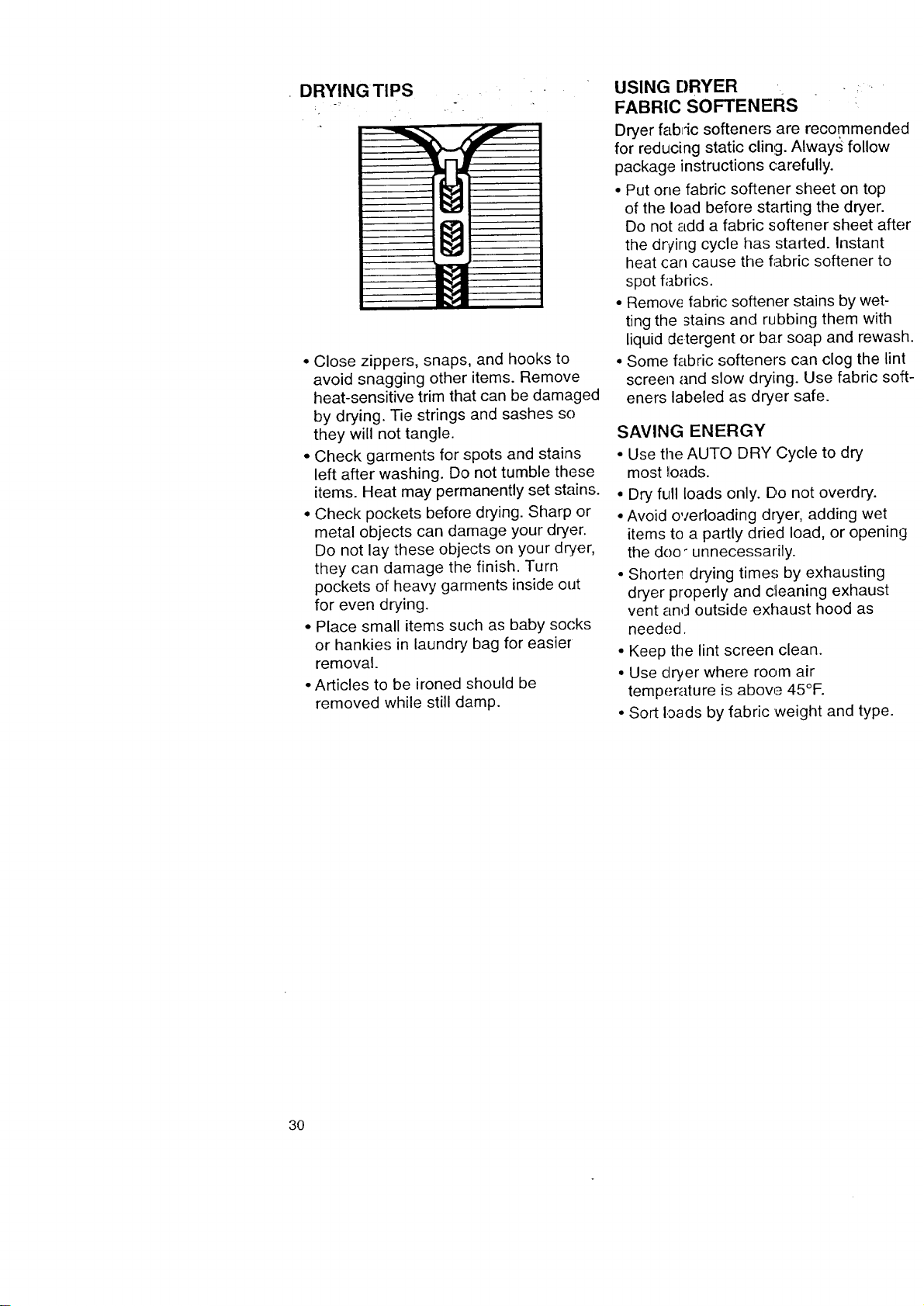
DRYING TIPS
• Close zippers, snaps, and hooks to
avoid snagging other items. Remove
heat-sensitive trim that can be damaged
by drying. Tie strings and sashes so
they will not tangle.
• Check garments for spots and stains
left after washing. Do not tumble these
items. Heat may permanently set stains.
• Check pockets before drying. Sharp or
metal objects can damage your dryer.
Do not lay these objects on your dryer,
they can damage the finish. Turn
pockets of heavy garments inside out
for even drying.
• Place small items such as baby socks
or hankies in laundry bag for easier
removal.
• Articles to be ironed should be
removed while still damp.
USING DRYER . , •
FABRIC SOFTENERS
Dryer fab:ic softeners are recommended
for reducing static cling. Always follow
package instructions carefully.
° Put one fabric softener sheet on top
of the load before starting the dryer.
Do not add a fabric softener sheet after
the dq/ing cycle has started. Instant
heat carl cause the fabric softener to
spot fabrics.
• Remove fabric softener stains by wet-
ting the stains and rubbing them with
liquid detergent or ba.r soap and rewash.
• Some fabric softeners can clog the lint
screen and slow drying. Use fabric soft-
eners labeled as dryer safe.
SAVING ENERGY
• Use the AUTO DRY Cycle to dry
most loads.
• Dry full loads only. Do not overdry.
• Avoid overloading dryer, adding wet
items to a partly dried load, or opening
the doo" unnecessarily.
• Shorter drying times by exhausting
dryer properly and cleaning exhaust
vent and outside exhaust hood as
needed.
• Keep the lint screen clean.
• Use dryer where room air
temperature is above 45°R
• Sort loads by fabric weight and type.
30
This section explains how to care for
your dryer properly and safely.
Proper care of your dryer can extend
its life and help you avoid costly
service calls.
EXTERIOR
Use a soft, damp cloth to clean the
cabinet and console. Avoid using harsh
abrasives. Do not put sharp metal
objects on or in your dryer. They can
damage the finish.
INTERIOR
Explosion Hazard
Use nonflammable cleaners.
Failure to do so can result in death,
explosion, or fire.
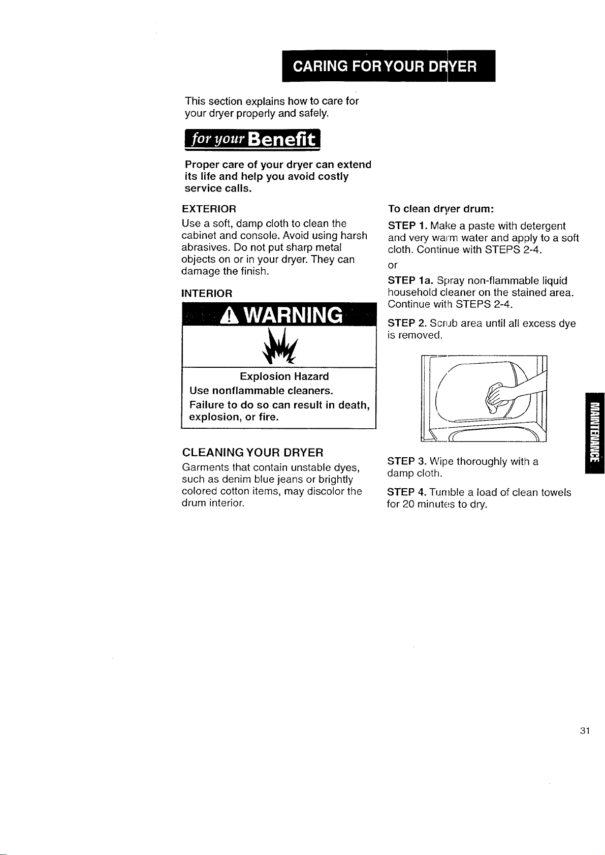
To clean dryer drum:
STEP 1. Make a paste with detergent
and very warm water and apply to a soft
cloth. Continue with STEPS 2-4.
or
STEP la. Spray non-flammable liquid
household cleaner on the stained area.
Continue with STEPS 2-4.
STEP 2. Scrub area until all excess dye
is removect.
CLEANING YOUR DRYER
Garments that contain unstable dyes,
such as denim blue jeans or brightly
colored cotton items, may discolor the
drum interior.
STEP 3. Wipe thoroughly with a
damp cloth.
STEP 4. Tumble a load olr clean towels
for 20 minutes to dry.
31
CLEANING THE LINT SCREEN
Remove Lint Before Every Load
The lint screen is located in the door
opening. Remove lint before every
load. A screen blocked by lint can
increase drying time.
To clean:
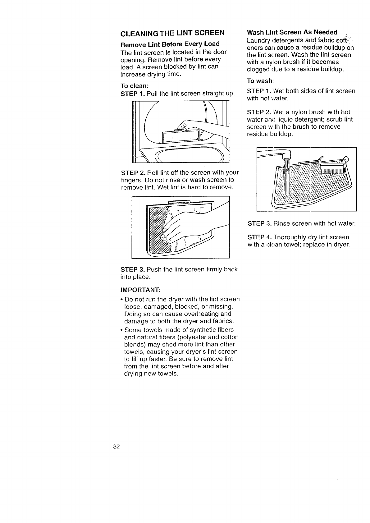
STEP 1. Pull the lint screen straight up.
STEP 2. Roll lint off the screen with your
fingers. Do not rinse or wash screen to
remove lint. Wet lint is hard to remove.
II;
III
!11
Iii
Wash Lint Screen As Needed
Laundry detergents and fabric soft-
eners can cause a residue buildup on
the lint screen. Wash the lint screen
with a nylon brush if it becomes
clogged due to a residue buildup.
To wash:
STEP 1. Wet both sides of lint screen
with hot water.
STEP 2. 'Net a nylon brush with hot
water and liquid detergent; scrub lint
screen w th the brush to remove
residue buildup.
STEP 3. Rinse screen with hot water.
STEP 4. Thoroughly dry lint screen
with a clean towel; replace in dryer.
STEP 3. Push the lint screen firmly back
into place.
IMPORTANT:
• Do not run the dryer with the lint screen
loose, damaged, blocked, or missing.
Doing so can cause overheating and
damage to both the dryer and fabrics.
• Some towels made of synthetic fibers
and natural fibers (polyester and cotton
blends) may shed more lint than other
towels, causing your dryer's lint screen
to fill up faster. Be sure to remove lint
from the lint screen before and after
drying new towels.
32
CHECKING FOR AIR FLOW
OBSTRUCTION
From time to time, you may find it helpful
to check your dryer and exhaust system
for proper air flow. Poor air flow can
result in longer drying times.
To check for air flow obstruction:
STEP 1. Check to ensure nothing is
blocking ventilation slots on dryer rear
panel.
STEP 2. Inspect exhaust hood. It should
not be blocked or obstructed.
REMOVING ACCUMULATED LINT
Lint can gather inside the exhaust
vent or dryer and be a fuel for fire. Lint
should be removed every 2 to 3 years,
or more often, depending on dryer usage.
Cleaning should be done by a qualified
service person.
To remove accumulated lint from
exhaust vent:
STEP 1. Disconnect exhaust vent from
the dryer.
STEP 2. Clean one section of vent at
a time until you reach the exhaust hood.
To clean out lint, you can use the hose
attachment on your vacuum or, use a
pole or wire with a feather duster or rag
attached.
STEP 3. Reconnect vent as described in
the "INSTALLATION INSTRUCTIONS" of
this Owner's Manual.
L__J
To remove accumulated lint from
inside the dryer:
Electrical Shock Hazard
Disconnect power before cleaning.
Replace a!l panels before operating.
Failure to follow these instructions
can result in death or electrical
shock.
STEP 1. Unplug the power supply cord
or turn off the electrical power supply.
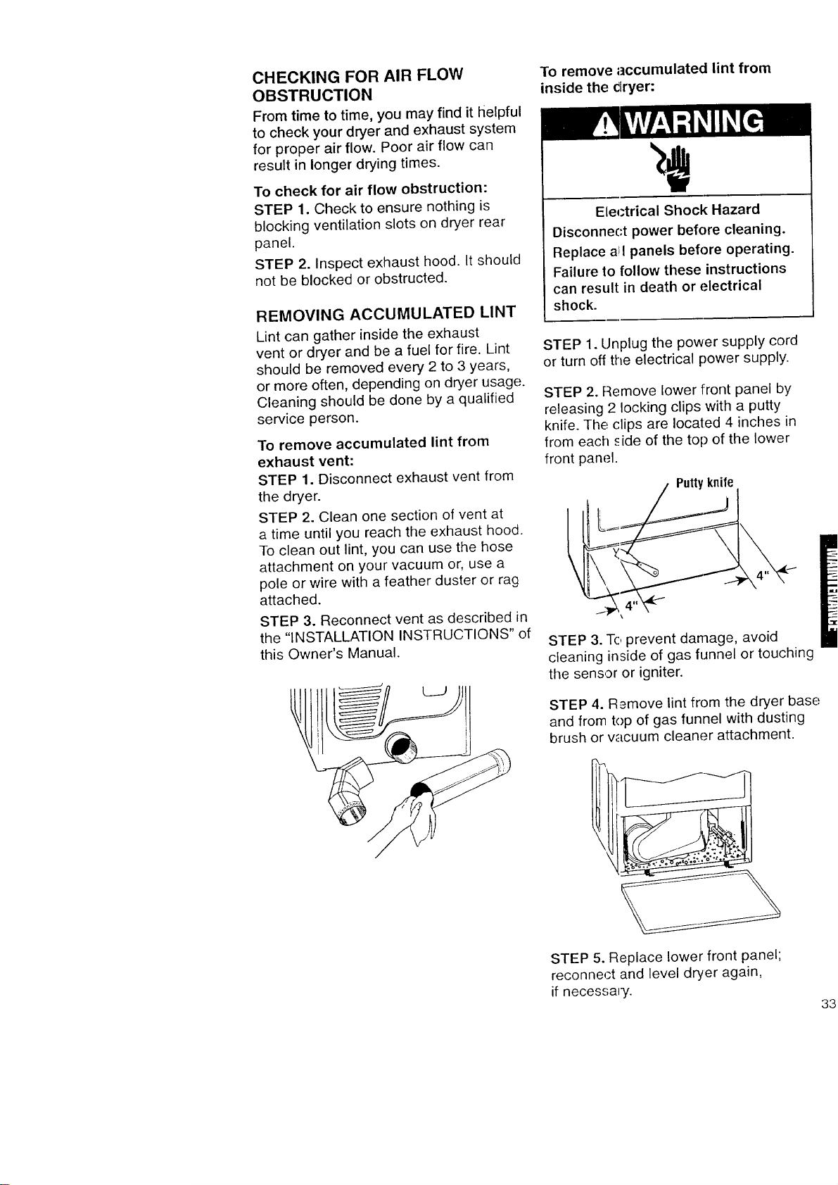
STEP 2. Remove lower front panel by
releasing 2 locking clips with a putty
knife. The clips are located 4 inches in
from each side of the top of the lower
front panel.
Putty knife
STEP 3. To prevent damage, avoid
cleaning inside of gas funnel or touchin(
the sensor or igniter.
STEP 4. Remove lint from the dryer ba._
and from top of gas funnel with dusting
brush or vacuum cleaner attachment.
STEP 5. Replace lower front panel;
reconnect and level dryer again,
if necessal¥.
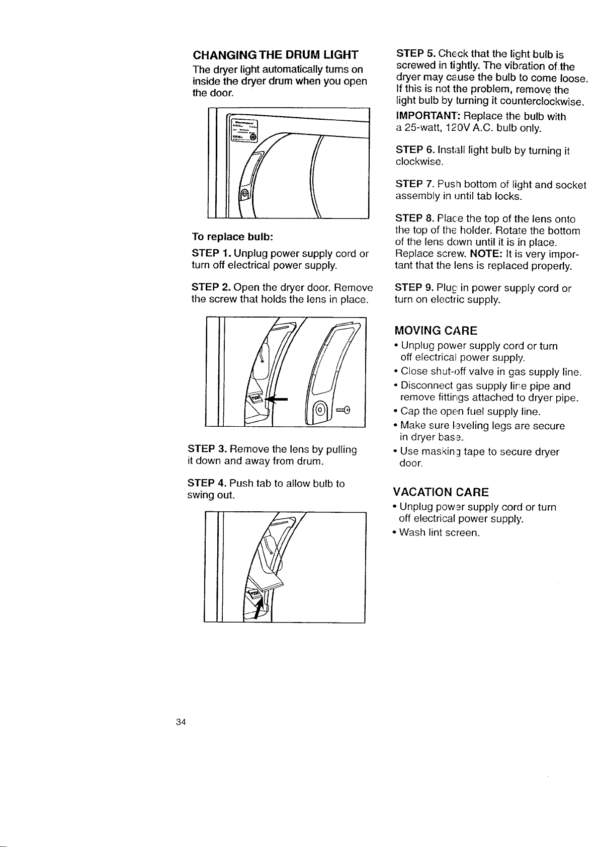
CHANGING THE DRUM LIGHT
The dryer light automatically turns on
inside the dryer drum when you open
the door.
!/
To replace bulb:
STEP 1. Unplug power supply cord or
turn off electrical power supply.
STEP 2. Open the dryer door. Remove
the screw that holds the lens in place.
i
i
STEP 3. Remove the lens by pulling
it down and away from drum.
STEP 4. Push tab to allow bulb to
swing out.
STEP 5. Check that the lightbulb is
screwed in tightly. The vibration ofthe
dryer may cause the bulb to come loose.
If this is not the problem, remov e the
light bulb by turning it ('ounterclockwise.
IMPORTANT: Replace the, bulb with
a 25-watt, 120VA.C. bulb only.
STEP 6. Install light bulb by turning it
clockwise.
STEP 7. Push bottom of light and socket
assembly in until tab locks.
STEP 8. Place the top of the lens onto
the top of the holder. Rotate the bottom
of the lens down until it is in place.
Replace screw. NOTE: It is very impor-
tant that the lens is replaced properly.
STEP 9. Plucj in power supply cord or
turn on electric supply.
MOVING CARE
• Unplug power supply cord or turn
off electrical power supply.
• Close shut-off valve in gas supply line.
• Disconnect gas supply line pipe and
remove fittings attached to dryer pipe.
• Cap the open fuel supply line.
• Make sure leveling legs are secure
in dryer base.
• Use masking tape to secure dryer
door.
VACATION CARE
• Unplug power supply cord or turn
off electrical power supply.
• Wash lint screen.
34
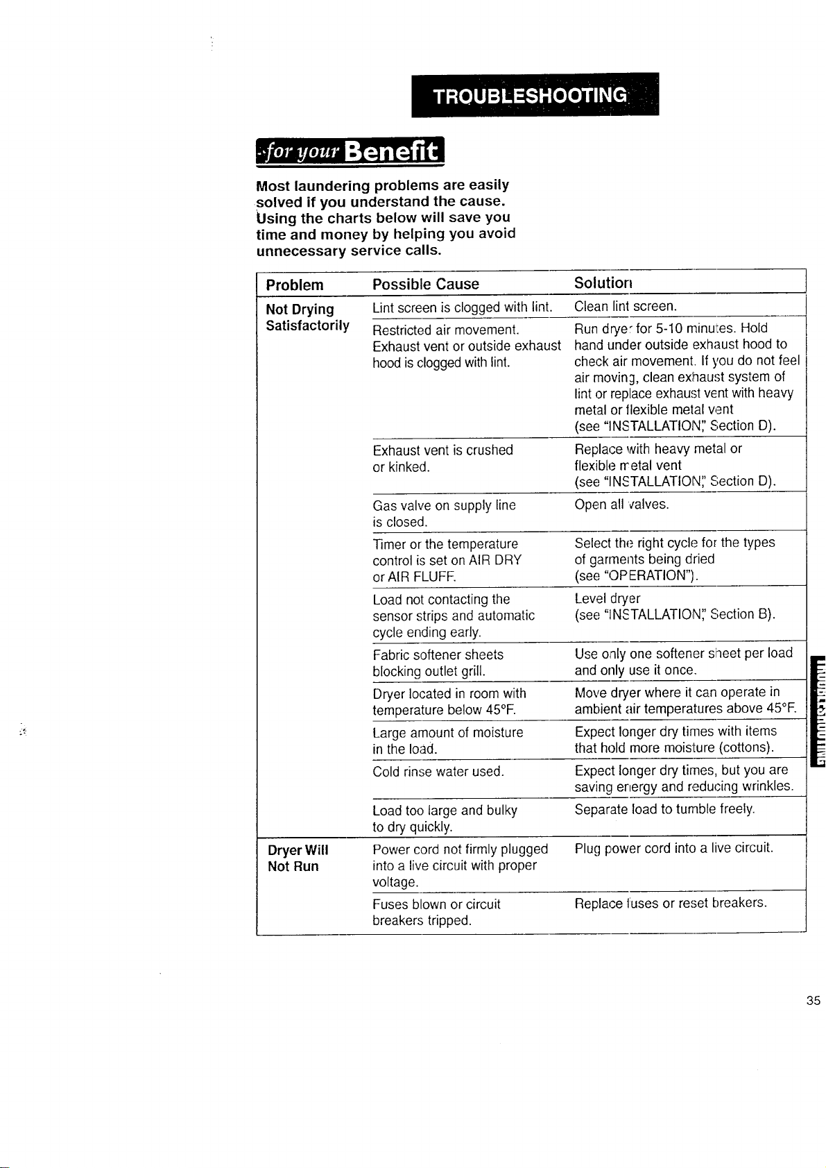
Most laundering problems are easily
solved if you understand the cause.
Using the charts below will save you
time and money by helping you avoid
unnecessary service calls.
Problem Possible Cause Solution
Not Drying Lintscreen is clogged with lint. Clean lint screen.
Satisfactorily Restricted air movement.
Exhaust vent or outside exhaust
hood is clogged with lint.
Run dryer for 5-10 minutes. Hold
hand under outside exhaust hood to
check air movement. If you do not feel
air movin;], clean exlnau,stsystem of
lint or replace exhaust vent with heavy
metal or flexible metal vent
(see "INSTALLATION',' Section D).
Exhaust vent is crushed Replace with heavy metal or
or kinked, flexible rretal vent
(see "INSTALLATION',' Section D).
Gas valve on supply line Open all valves.
is closed.
Timer or the temperature Select the right cycle for the types
control is set on AIR DRY of garments being dried
or AIR FLUFF. (see "QPERATION").
Load not contacting the Level dryer
sensor strips and automatic (see "INSTALLATION',' Section B).
cycle ending early.
Fabric softener sheets Use only one softener siqeet per load
blocking outlet grill, and only use it once.
Dryer located in room with Move dryer where it can operate in
temperature below 45°F. ambient air temperatures above 45°F.
Large amount of moisture Expect longer dry times with items
in the load. that hold more moisture (cottons).
Cold rinse water used. Expect longer dry times, but you are
savincl energy and reducing wrinkles.
Load too large and bulky Separate load to tumble freely.
to dry quickly.
Dryer Will Power cord not firmly plugged Plug power cord into a live circuit.
Not Run into a live circuit with proper
voltage.
Fuses blown or circuit Replace luses or reset breakers.
breakers tripped.
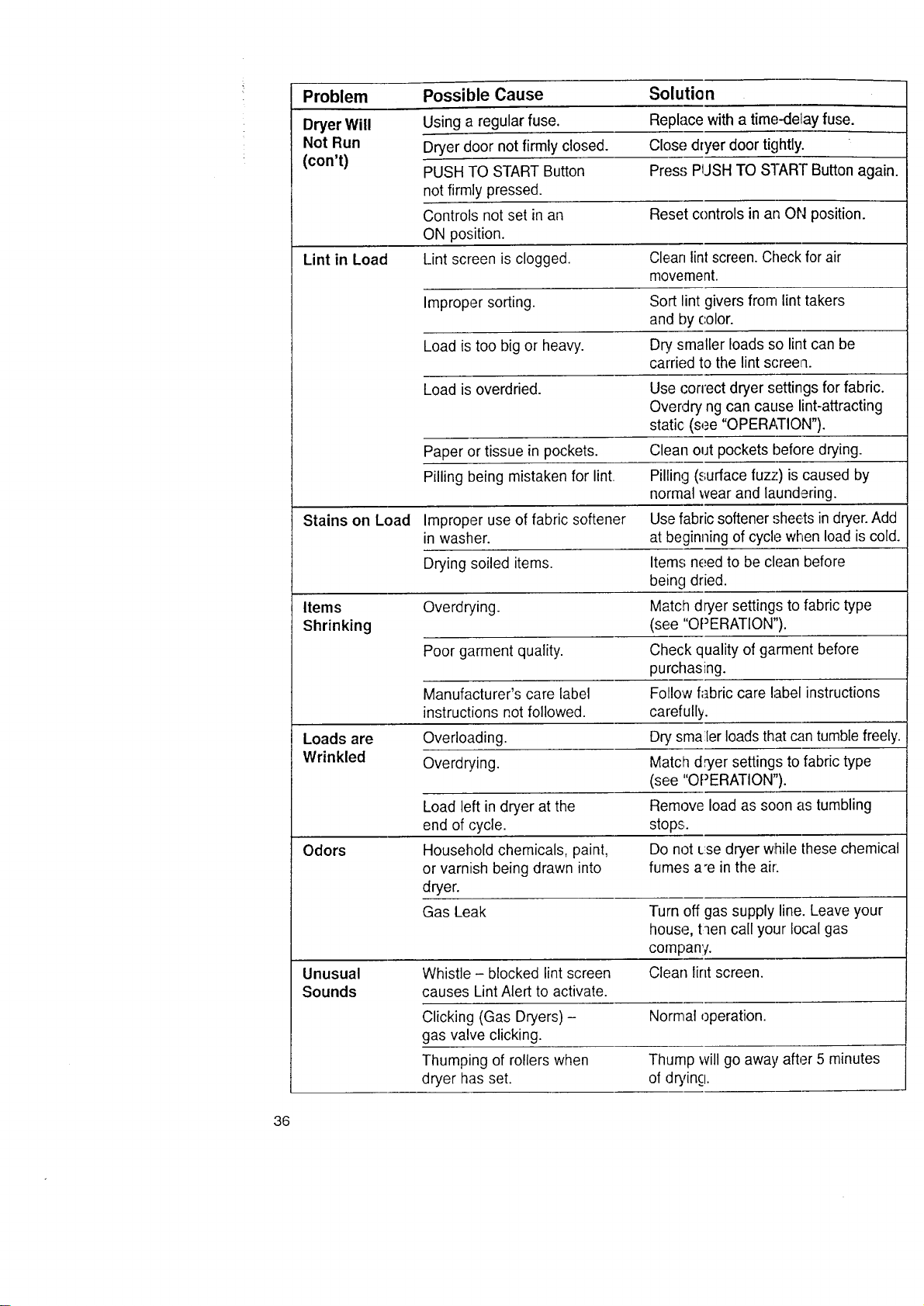
Problem Possible Cause Solution
Dryer Will Using a regular fuse. Replace with a time-detlayfuse.
Not Run Dryer door not firmly closed. Close dryer door tightly.
(con't)
PUSH TO START Button Press PUSH TO START Button again.
not firmly pressed.
Controls not set in an Reset controls in an ON position.
ON position.
Lint in Load Lint screen is clogged. Clean lint screen. Checkfor air
movement.
Improper sorting. Sort lint givers from lint takers
and by color.
Load is too big or heavy. Dry smaller loads so lint can be
carried to the lint screen.
Load is overdried. Use correct dryer settings for fabric.
Overdry ng can cause lint-attracting
static (see "OPERATION").
Paper or tissue in pockets. Clean out pockets before drying.
Pilling being mistaken for lint. Pilling (surface fuzz) is caused by
normal wear and laundering.
Stains on Load Improper use of fabric softener Use fabric softener sheets in dryer. Add
in washer, at beginning of cycle when load is cold.
Drying soiled items. Item.:;need to be clean before
beinq dried.
Items Overdrying. Matc!ndryer settings to fabric type
Shrinking (see "OPERATION").
Poor garment quality. Check quality of garment before
purchasing.
Manufacturer's care label Follow fabric care label instructions
instructions not followed, carefully.
Loads are Overloading. Dry sma ler loads that can tumble freely.
Wrinkled Overdrying. Matcln dryer settings to fabric type
(see "OPERATION").
Load left in dryer at the Remove load as soon as tumbling
end of cycle, stops.
Odors Household chemicals, paint, Do not Lse dryer wlhile these chemical
or varnish being drawn into fumes a'e in the air.
dryer.
Gas Leak Turn off gas supply line. Leave your
house, t'len call your local gas
company.
Unusual Whistle - blocked lint screen Clean lint screen.
Sounds causes Lint Alert to activate.
Clicking (Gas Dryers)- Normal operation.
gas valve clicking.
Thumping of rollers when Thump will go away after 5 minutes
dryer has set. of dryincI.
36
KENMORE DRYERS
We Service What We Sell
"We Service What We Sell" is our
assurance that you can depend on Sears
for service. Your Gas Dryer has added
value when you consider that Sears
has service units nationwide, staffed
with professional technicians specifically
trained on Sears appliances and having
the parts, tools, and equipment to ensure
that we meet our pledge to you...
"We Service What We Sell:
Sears Maintenance Agreement
Maintain the value of your Kenmore
Gas Dryer with a Sears Maintenance
Agreement. Kenmore Gas Dryers are
designed, manufactured, and tested
for years of dependable operation.
Yet any appliance may require service
from time to time.
The Sears Maintenance Agreement
• Is your way to buy tomorrow's
sen/ice at today's prices.
• Eliminates repair bills resulting
from normal use.
• Allows for as many service calls
as required.
° Provides for service by professional
Sears Trained Technicians.
• Ew.,n if you don't need repairs, the
Maintenance Agreement offers an
annual preventative maintenance
checkup at your request!
For more information,
call 1-800-827-6655.
37
Forthe repair or replacementpartsyou
needdelivereddirectlytoyourhome
Call7 am - 7 pm, 7 claysaweek
1-800-366-PART
(1-800-366-7278)
Forin-home major brand repairservice
Call24 hours aday,7 daysaweek
1-8OO-4-REPAIR
(1-800-473-7247)
Forthe locationof a SearsParts and
Repair Center inyourarea
Call24 hours aday,7 daysa week
1-800-488-1222
mm
""ilN
mm
mmmmmmm
mmmmmmm
For informationonpurchasing a Sears
MaintenanceAgreementorto inquire
aboutan existingAgreement
Call9 am - 5 pro, Monday- Saturday
1-800-827-6655
Whenrequestingserviceorordering
pads,alwaysgivethefollowing
information:
• ProductName • PartName
• ModelNumber • PartNumber
I
6 /AURS
38
America'sRepairSpecia/ists