Loading ...
Loading ...
Loading ...
II IIIIIIIII II I II IIIIIII III I llllll
iiiiiiii I IIIIII I minim lull I l IIIIII II I II
SERVICE - CUSTOMER RESPONSIBILITIES
Jllll II III I II n III il ii mill IIII _IUI[[IIIIIIII IIIIUI
A. MAINTENANCE SAFETY
1. Maintain the unit according to recom-
mended procedures.
2. Never start the unit with the blade guard re-
moved. The blade can throw debris, which can
result in serious injury.
3. Disconnect power source before perform-
ing maintenance.
I l IIIIIIIIIIIII IIIIUIIIlIIIIilIIIIIIUlIIIIUIIIIIIIIIIIIII I I
B. MAINTENANCE - BLADE
4. Replace blade parts that are cracked,
chipped, broken, or damaged in any other
way before using the unit.
5. Use only genuine SEARS replacement
paints as recommended.
6. Inspect the entire unit. Replace damaged
parts. Make sure all fasteners are in place and se-
curely fastened.
III I lj l
L A WAP_xrING I
The blade will spin momentarily after the motor I
stops. Make sure the blade has stopped _gl
and disconnect the unit from the power source i
before performing work on the blade. [
Wear protective gloves when
.......handling or performing maintenance on
the blade to help avoid injury.
• Use the proper replacement blade. Contact your
SEARS Store for the proper part number.
• The blade is reversible. When the cutting edge on
one side becomes worn, turn the blade over.
• Check blade for flatness periodically. Lay the
blade on a fiat surface and inspect the blade for
flatness. Throw away a blade that is not flat.
A WARNING , '...... I
Always replace a blade that is bent, warped,[
cracked, broken, or damaged in any other way. [
Never attempt to straighten and re-use a dam- [
aged blade. Use only the specified replacement [
blade. _ I
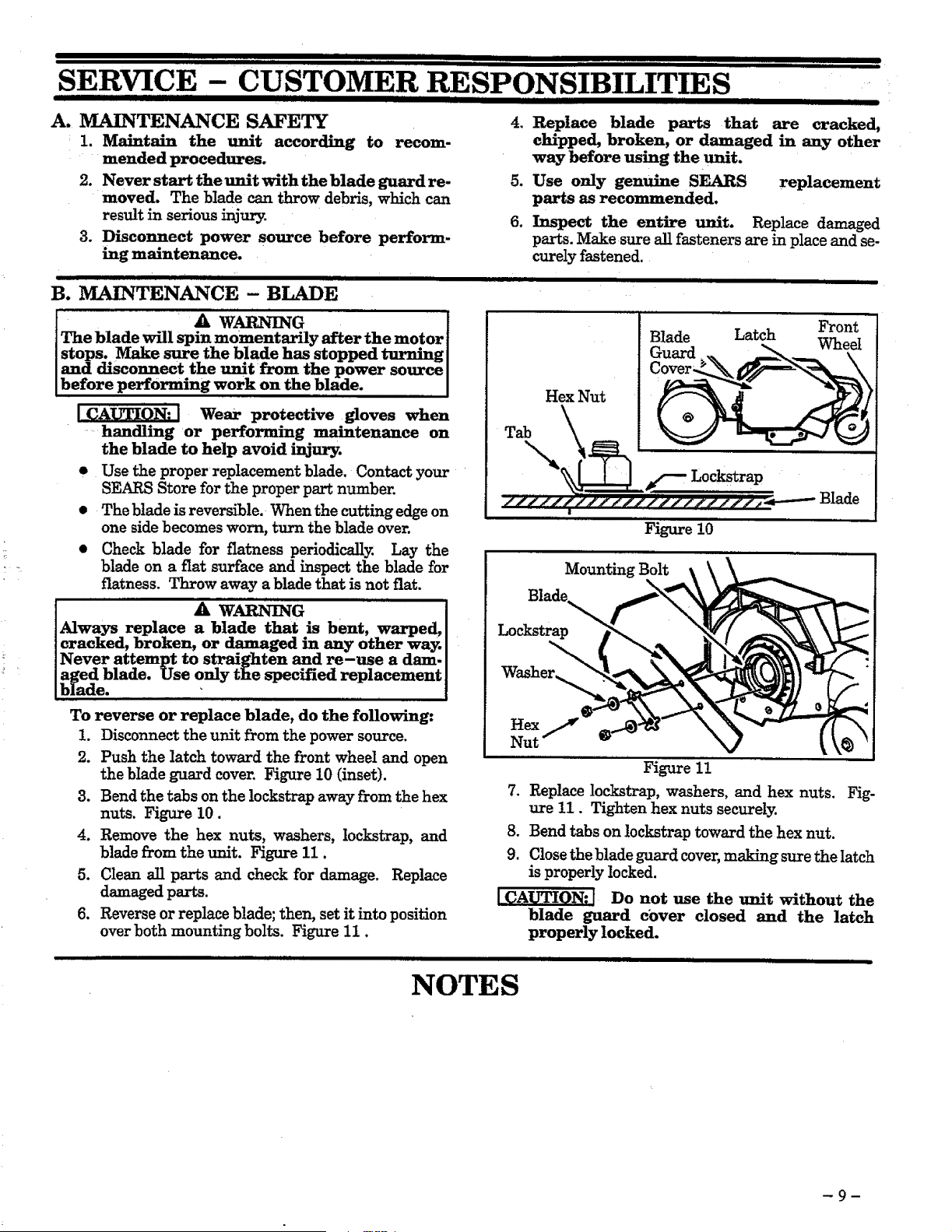
To reverse or replace blade, do the following:
1. Disconnect the unit from the power source.
2. Push the latch toward the front wheel and open
the blade guard cover. Figure 10 (inset).
3. Bend the tabs on the lockstrap away from the hex
nuts. Figure 10.
4. Remove the hex nuts, washers, lockstrap, and
blade from the unit. Figure 11.
Bhde
Guard
Latch Front
Wheel
Figure 10
Mounting Bolt
\
Lockstrap
Washer_
Hex
Nut
5+ Clean all parts and check for damage. Replace
t
Figure 1!
7. Replace lockstrap, washers, and hex nuts. Fig-
ure 11. Tighten hex nuts securely.
8. Bend tabs on lockstrap toward the hex nut.
9. Close the blade guard cover, making sure the latch
is properly locked.
ICAUTION: I Do not use the unit without the
blade guard cover closed and the latch
properly locked.
damaged parts.
Reverse or replace blade; then, set it into position
over both mounting bolts. Figure 11.
NOTES
Loading ...
Loading ...
Loading ...