Home
Bookmarks
Home
Fnirsi
Fnirsi 1014D User Manual
Page 6
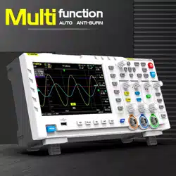
Fnirsi 1014D Desktop Oscilloscope 100mhz*2 1gs/s 2 In 1 Dual Channel Digital Oscilloscope 10mhz Signal Generator
Product instructions - Page 6
For 1014D.
PDF File Manual
,
22 pages
,
Read Online
|
Download pdf file
More photos
Product Introduction
Serious Warning
Solemnly Remind
Interface Function Indicator Diagram
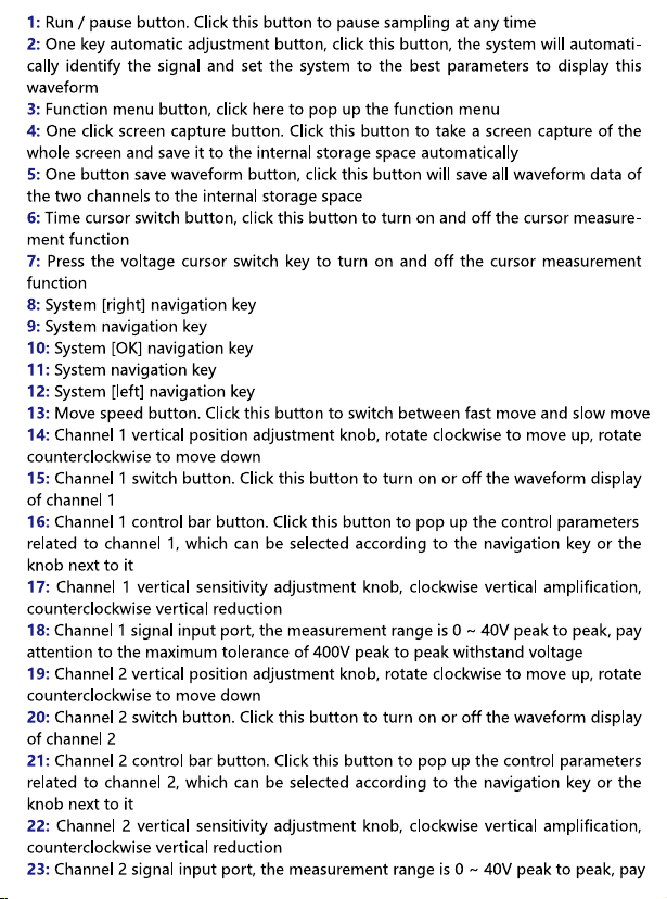
Button Function Indication Diagram
Operating Instructions (oscilloscope Part)
Open Or Close Channel 1 / Channel 2
Setting Input Coupling Mode
Set The Probe Input Ratio
Scaling Waveform
Moving Waveform
Adjust Trigger Voltage
Set Trigger Edge
Set Auto Trigger
Set Single Trigger
Set Normal Trigger
Pause Display
Automatic Waveform Adjustment
Set The Slow Scan Scrolling Mode
Time Cursor Measurement
Voltage Cursor Measurement
Set The Parameters To Be Displayed
Full Screen Capture
Save Current Waveform Data
Adjust The Screen Brightness
Adjust The Background Grid Brightness
Setting Automatic 50% Trigger All The Time
Horizontal Baseline Offset Calibration
View The Saved Screen Capture
View The Saved Waveform Data
Delete The Saved Waveform
Connect The Computer To View The Screen Capture Pictures
Operation Instruction (signal Generator Part)
Switch The Waveform Type
Adjust The Waveform Frequency
Adjust The Duty Cycle Of Square Wave
Capture Waveform
Output The Captured Waveform As The Signal Generator
Analysis Of Common Problems
Test Methods Of Common Circuits
Battery Or DC Voltage Measurement
Crystal Vibration Measurement
PWM Signal Measurement Of MOS Tube Or IGBT
Signal Generator Output Measurement
Measurement Of Domestic Electricity At 220V Or 110V
Power Ripple Measurement
Inverter Output Measurement
Measurement Of Power Amplifier Or Audio Signal
Measurement Of Vehicle Communication Signal / Bus Signal
Infrared Remote Receiver Measurement
Measurement Of Amplification Circuit With Sensors
Page 6/22
Page 1
Page 2
Page 3
Page 4
Page 5
Page 6
Page 7
Page 8
Page 9
Page 10
Page 11
Page 12
Page 13
Page 14
Page 15
Page 16
Page 17
Page 18
Page 19
Page 20
Page 21
Page 22
Contents
Table of Contents
Previous
Next
Bookmarks
Loading ...
Loading ...
Loading ...
Loading ...
Loading ...
Loading ...
File type: PDF
File name: 77414308_1014d.pdf
File size: 7.65 MB
Rating:
File Language: English
Pages: 22
Author: Fnirsi
File created: 2023-04-07
Published: 2023-04-08
Updated: 2023-10-04
Verified by
Jaqueline Hayes
on 2023-10-04
Download File
Table of Contents
×
Product Introduction
2
Serious Warning
2
Solemnly Remind
3
Interface Function Indicator Diagram
4
Button Function Indication Diagram
5
Operating Instructions (oscilloscope Part)
8
Open Or Close Channel 1 / Channel 2
8
Setting Input Coupling Mode
8
Set The Probe Input Ratio
8
Scaling Waveform
8
Moving Waveform
8
Adjust Trigger Voltage
8
Set Trigger Edge
9
Set Auto Trigger
9
Set Single Trigger
9
Set Normal Trigger
9
Pause Display
9
Automatic Waveform Adjustment
9
Set The Slow Scan Scrolling Mode
9
Time Cursor Measurement
9
Voltage Cursor Measurement
9
Set The Parameters To Be Displayed
9
Full Screen Capture
10
Save Current Waveform Data
10
Adjust The Screen Brightness
10
Adjust The Background Grid Brightness
10
Setting Automatic 50% Trigger All The Time
10
Horizontal Baseline Offset Calibration
10
View The Saved Screen Capture
10
View The Saved Waveform Data
10
Delete The Saved Waveform
10
Connect The Computer To View The Screen Capture Pictures
11
Operation Instruction (signal Generator Part)
11
Switch The Waveform Type
11
Adjust The Waveform Frequency
11
Adjust The Duty Cycle Of Square Wave
11
Capture Waveform
11
Output The Captured Waveform As The Signal Generator
12
Analysis Of Common Problems
13
Test Methods Of Common Circuits
15
Battery Or DC Voltage Measurement
15
Crystal Vibration Measurement
16
PWM Signal Measurement Of MOS Tube Or IGBT
17
Signal Generator Output Measurement
17
Measurement Of Domestic Electricity At 220V Or 110V
18
Power Ripple Measurement
18
Inverter Output Measurement
19
Measurement Of Power Amplifier Or Audio Signal
19
Measurement Of Vehicle Communication Signal / Bus Signal
20
Infrared Remote Receiver Measurement
20
Measurement Of Amplification Circuit With Sensors
21