ZHEJIANG DAHUA VISION TECHNOLOGY CO.LTD. V2.0.2
Alarm Hub
User's Manual
Important Safeguards and Warnings
This section introduces content covering the proper handling of the device, hazard prevention, and
prevention of property damage. Read carefully before using the device, and comply with the
guidelines when using it.
Operation Requirements
●
Make sure that the power supply of the device works properly before use.
●
Do not pull out the power cable of the device while it is powered on.
●
Only use the device within the rated power range.
●
Transport, use and store the device under allowed humidity and temperature conditions.
●
Prevent liquids from splashing or dripping on the device. Make sure that there are no objects
lled with liquid on top of the device to avoid liquids owing into it.
●
Do not disassemble the device.
Installation Requirements
●
Connect the device to the adapter before power on.
●
Strictly abide by local electrical safety standards, and make sure that the voltage in the area is
steady and conforms to the power requirements of the device.
●
Do not connect the device to more than one power supply. Otherwise, the device might
become damaged.
●
Observe all safety procedures and wear required protective equipment provided for your use
while working at heights.
●
Do not expose the device to direct sunlight or heat sources.
●
Do not install the device in humid, dusty or smoky places.
●
Install the device in a well-ventilated place, and do not block the ventilator of the device.
●
Use the power adapter or case power supply provided by the device manufacturer.
●
The power supply must conform to the requirements of ES1 in IEC 62368-1 standard and be no
higher than PS2. Note that the power supply requirements are subject to the device label.
●
Connect class I electrical appliances to a power socket with protective earthing.
User's Manual
I

Foreword
General
This manual introduces the installation, functions and operations of the alarm hub (hereinafter
referred to as the "hub"). Read carefully before using the device, and keep the manual safe for
future reference.
Safety Instructions
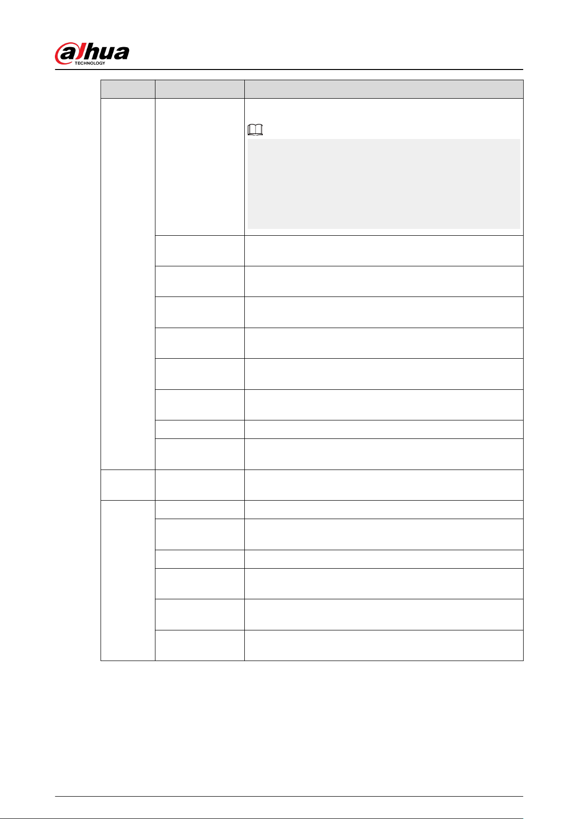
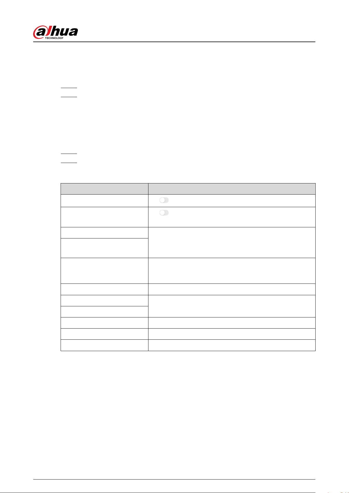
The following signal words might appear in the manual.
Signal Words Meaning
Indicates a high potential hazard which, if not avoided, will result in
death or serious injury.
Indicates a medium or low potential hazard which, if not avoided,
could result in slight or moderate injury.
Indicates a potential risk which, if not avoided, could result in
property damage, data loss, lower performance, or unpredictable
result.
Provides methods to help you solve a problem or save you time.
Provides additional information as the emphasis and supplement to
the text.
Revision History
Version Revision Content Release Time
V2.0.2
●
Added IPC conguration and alarm-video
linkage conguration.
●
Updated SIA event codes.
●
Added ATS category: SP2/DP2 in technical
specication.
August 2023
V2.0.1
●
Updated device basic conguration function.
●
Updated viewing status function.
●
Updated conguring the hub function.
●
Updated wired network conguration function.
April 2023
V2.0.0
●
Added network congurations.
●
Added arming failure events and descriptions.
●
Added SIA event codes and descriptions.
November 2022
V1.1.0
●
Added operations on COS Pro and DMSS app.
●
Added user management.
●
Updated images.
●
Updated descriptions of parameters.
February 2022
User's Manual
II

Version Revision Content Release Time
V1.0.0 First release. October 2021
Privacy Protection Notice
As the device user or data controller, you might collect the personal data of others such as their
face, ngerprints, and license plate number. You need to be in compliance with your local privacy
protection laws and regulations to protect the legitimate rights and interests of other people by
implementing measures which include but are not limited: Providing clear and visible identication
to inform people of the existence of the surveillance area and provide required contact information.
About the Manual
●
The manual is for reference only. Slight dierences might be found between the manual and the
product.
●
We are not liable for losses incurred due to operating the product in ways that are not in
compliance with the manual.
●
The manual will be updated according to the latest laws and regulations of related jurisdictions.
For detailed information, see the paper user’s manual, use our CD-ROM, scan the QR code or
visit our ocial website. The manual is for reference only. Slight dierences might be found
between the electronic version and the paper version.
●
All designs and software are subject to change without prior written notice. Product updates
might result in some dierences appearing between the actual product and the manual. Please
contact customer service for the latest program and supplementary documentation.
●
There might be errors in the print or deviations in the description of the functions, operations
and technical data. If there is any doubt or dispute, we reserve the right of nal explanation.
●
Upgrade the reader software or try other mainstream reader software if the manual (in PDF
format) cannot be opened.
●
All trademarks, registered trademarks and company names in the manual are properties of their
respective owners.
●
Please visit our website, contact the supplier or customer service if any problems occur while
using the device.
●
If there is any uncertainty or controversy, we reserve the right of nal explanation.
User's Manual
III

Table of Contents
Important Safeguards and Warnings.................................................................................................................I
Foreword............................................................................................................................................................. II
1 Introduction..................................................................................................................................................... 1
1.1 Overview........................................................................................................................................................................................1
1.2 Technical Specications...........................................................................................................................................................1
1.3 Checklist.........................................................................................................................................................................................6
2 Design............................................................................................................................................................... 7
2.1 Appearance...................................................................................................................................................................................7
2.2 Dimensions................................................................................................................................................................................... 8
3 Startup.............................................................................................................................................................. 9
3.1 Users................................................................................................................................................................................................ 9
3.2 Operation Process....................................................................................................................................................................10
4 Dolynk Care Operations for Installers..........................................................................................................12
4.1 Logging into Dolynk Care..................................................................................................................................................... 12
4.2 Adding Devices.........................................................................................................................................................................14
4.2.1 Adding the Hub............................................................................................................................................................14
4.2.2 Adding Peripherals......................................................................................................................................................20
4.3 Managing Users........................................................................................................................................................................ 20
4.3.1 Adding DMSS Admin Users......................................................................................................................................21
4.3.2 Deleting Users...............................................................................................................................................................24
4.4 Applying for DMSS Admin User's Permission................................................................................................................ 26
4.5 Delivering Devices to DMSS Admin User........................................................................................................................ 26
4.6 Operation and Device Health Maintenance...................................................................................................................27
4.6.1 Checking Device Health Status...............................................................................................................................27
4.6.2 Device Basic Congurations.................................................................................................................................... 27
4.6.3 Viewing Evaluations....................................................................................................................................................34
4.6.4 Fixing Errors...................................................................................................................................................................34
5 DMSS Operations for End Users................................................................................................................... 35
5.1 Logging in to DMSS.................................................................................................................................................................35
5.2 Adding Devices.........................................................................................................................................................................37
5.2.1 Adding the Hub............................................................................................................................................................37
5.2.2 Adding Peripheral....................................................................................................................................................... 37
5.2.3 Adding IPC......................................................................................................................................................................37
5.3 Conguring Alarm Linkage Video......................................................................................................................................41
5.4 Hub General Settings..............................................................................................................................................................42
5.5 Network Conguration.......................................................................................................................................................... 42
User's Manual
IV

5.5.1 Wired Network Conguration.................................................................................................................................42
5.5.2 Wi-Fi Network Conguration...................................................................................................................................43
5.5.3 Cellular Conguration................................................................................................................................................43
5.6 Managing Users........................................................................................................................................................................ 43
5.6.1 Adding User...................................................................................................................................................................43
5.6.2 Deleting User.................................................................................................................................................................46
6 General Operations....................................................................................................................................... 49
6.1 Single Arming and Disarming..............................................................................................................................................49
6.2 Global Arming and Disarming.............................................................................................................................................49
6.3 Manual Arming and Disarming...........................................................................................................................................50
6.4 Scheduled Arming and Disarming.....................................................................................................................................50
Appendix 1 Arming Failure Events and Description....................................................................................51
Appendix 2 SIA Event Codes and Description.............................................................................................. 53
Appendix 3 Cybersecurity Recommendations............................................................................................. 57
User's Manual
V

1 Introduction
1.1 Overview
Alarm hub is a central device in the security system, which controls the operation of all connected
peripherals. If the security system detects the presence, entry, or attempted entry of an intruder
into the armed area, the hub will receive the alarm signals from the detectors, and then alert users.
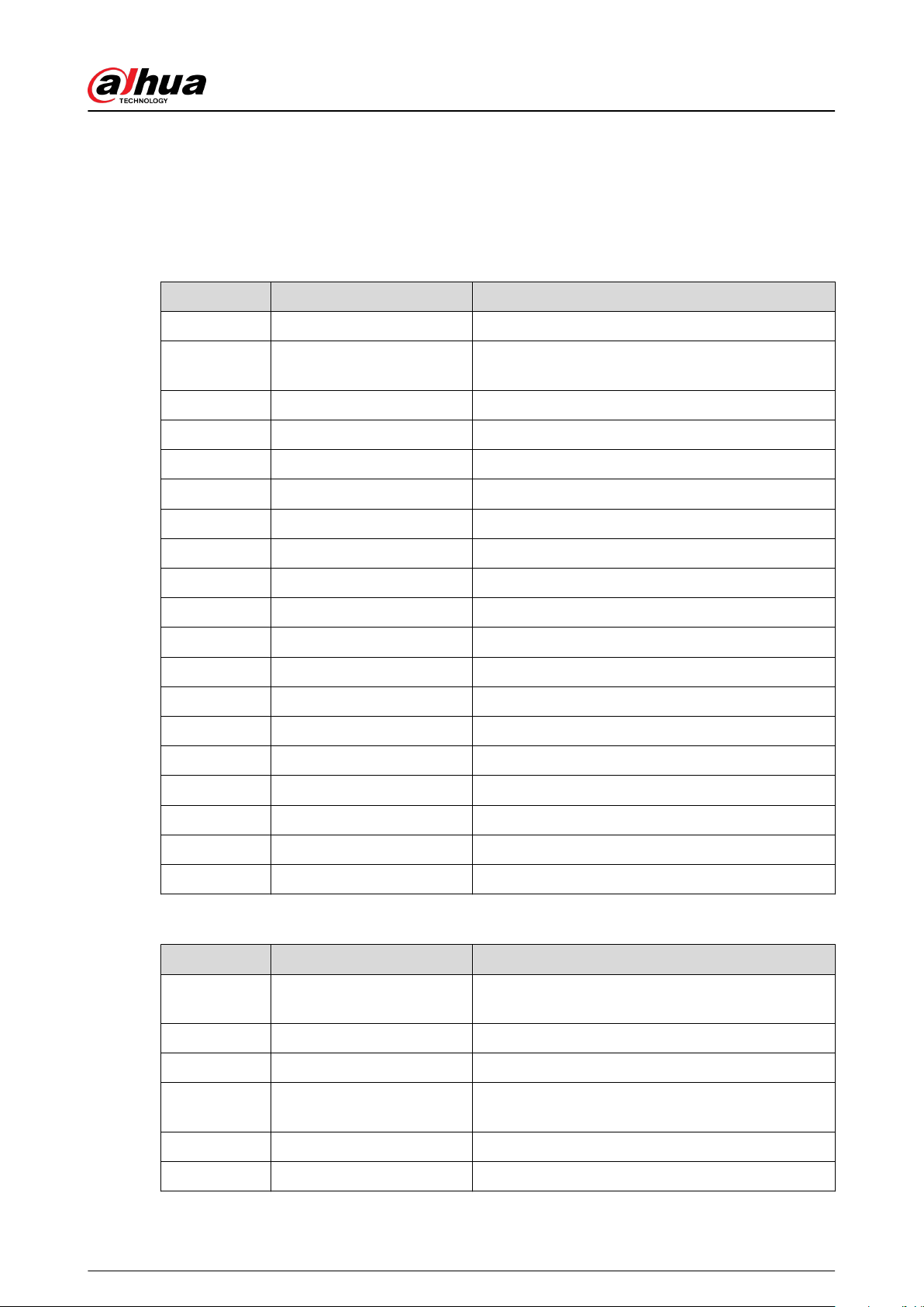
1.2 Technical Specications
This section contains technical specications of the device. Please refer to the ones that correspond
with your model.
Table 1-1 Technical specications
Type Parameter Description
Port
Network 1 RJ-45 10 M/100 M self-adaptive Ethernet port
GSM Single SIM (GSM:900/1800 MHz); dual SIM single standby
LTE
Single SIM (GSM: 900/1800 MHz, WCDMA: B1/B5/B8, LTE-FDD:
B1/B3/B5/B7/B8/B20, LTE-TDD:B38/B40/B41); dual SIM single
standby
Battery 12 V battery port
Indicator Light
1 for multiple statuses (alarm, arming, disarming, networking,
and malfunction)
Button 1 × reset, 1 × power, 1 × AP
Buzzer Built-in
Tamper 1 case tamper port for the alarm control panel
Function
SMS Notication
SMS alarm (up to 5 phone numbers)
Only available on select models.
Phone Call
Notication
Yes (up to 5 phone numbers)
Only available on select models.
Video Linkage Yes
Network Protocol TCP/IP, including PPTP, L2TP, DHCP, UPNP, and NTP
Remote Upgrade Cloud update
Conguration
Method
App
Arm and Disarm
Method
App, keypad, keyfob, schedule
User's Manual
1

Type Parameter Description
Number of
Peripherals
Max. 150-channel wireless peripherals (6 sirens, 64 wireless
keyfobs, 4 repeaters, and 8 keypads)
Area 32 areas (rooms)
Power
Management
Automatic switching between main power supply and storage
power supply
Alarm for main power loss
Alarm for battery loss and battery voltage fault
Event Logs Max. 5000
Power Failure
Protection for
Congured
Parameters
Yes
User Management Max. 8 users: 1 installer,1 administrator, 6 general users
Query
Searching for push messages, device status, and program
version. Detecting signal strength.
RF
Carrier Frequency
DHI-ARA3000H-FW2 (868)/
DHI-ARA3000H-GW2 (868)/
DHI-ARA3000H-W2 (868):
868.0 MHz–868.6 MHz
DHI-ARA3000H-FW2/DHI-
ARA3000H-GW2/DHI-
ARA3000H-W2:
433.1 MHz–434.6 MHz
Communication
Distance
DHI-ARA3000H-FW2 (868)/
DHI-ARA3000H-GW2 (868)/
DHI-ARA3000H-W2 (868):
Up to 2,000 m (6,561.68 ft) in
an open space
DHI-ARA3000H-FW2/DHI-
ARA3000H-GW2/DHI-
ARA3000H-W2:
Up to 1,200 m (3,937.01 ft) in an
open space
Transmission
Power
DHI-ARA3000H-FW2 (868)/
DHI-ARA3000H-GW2 (868)/
DHI-ARA3000H-W2 (868):
Limit 25 mW
DHI-ARA3000H-FW2/DHI-
ARA3000H-GW2/DHI-
ARA3000H-W2:
Limit 10 mW
Communication
Mechanism
Two-way
Encryption Mode AES128
Frequency
Hopping
Yes
RF Interference
Detection
For a 60-second detection, if the interference lasts longer than
30 seconds, the system reports the RF interference information.
Wi-Fi 2.4 G
Power
Supply
PS Type Type A
Main Power 12 VDC, 1.5 A
Battery Capacity 2x 3.6 V/2150 mAh
User's Manual
2
Type Parameter Description
Battery Standby
Up to 12 h
When following conditions are met, the standby time can reach
12 h:
●
Connects with Wi-Fi, GPRS/3G/4G.
●
Connects to ARC and heartbeat interval is 1800 seconds.
●
Connects to 8 inputs and 1 siren.
●
Connects to the cloud.
Battery Type
Battery type: Built-in rechargeable Lithium-ion polymer; battery
model: 18650
Max. current
available
3.5 A
Power
Consumption
Max. 15 W
Current
Consumption
Normal: 220 mA; alarm: 300 mA
Battery Low
Battery Threshold
3.5 VDC
Battery Restore
Threshold
3.7 VDC
Release Voltage < 3.358 V
Battery Recharge
Time
80% approx. 15 h
Audio and
Video
Video Input 4-channel IPC
ARC
Signaling
ATS Category DP2/SP2 (LAN/Wi-Fi and GPRS/4G)
Acknowledgment
Operation
Pass through
Protocols SIA-DC09
Primary
Transmission Path
LAN /Wi-Fi (NO 50136-2)
Secondary
Transmission Path
GPRS/4G
Notication
Equipment
C/E/F
User's Manual
3

Type Parameter Description
Certications
DHI-ARA3000H-FW2 (868)/
DHI-ARA3000H-GW2 (868)/
DHI-ARA3000H-W2 (868):
EN
50131-1:2006+A1:2009+A2:20
17+A3:2020
EN 50131-3:2009
EN 50131-6:2017
EN 50131-5-3:2017
EN 50131-10: 2014
EN 50136-2: 2013
Security Grade 2
Environmental Class II
ATS category: SP2/DP2
CE
DHI-ARA3000H-FW2/DHI-
ARA3000H-GW2/DHI-
ARA3000H-W2:
FCC
CE
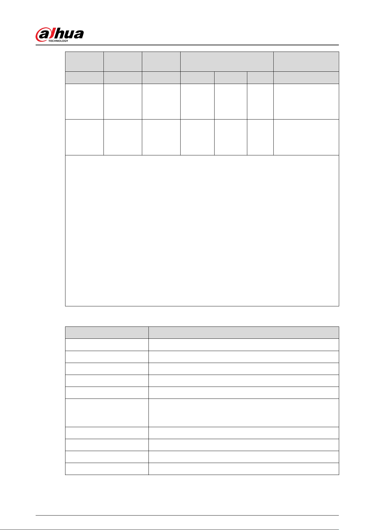
Table 1-2 ATE category
ATE
Category
Reporting
Time
Protocols Communication Devices
Communication
Device to be Used
PSTN 2G/3G IP
SP2 25 h Standard √
The check marked
communication
device
SP3 30 min Standard √ √
Only one of the two
check marked
communication
devices
SP4 3 min Encrypted √ √
Only one of the two
check marked
communication
devices
SP5 90 s Encrypted √ √
Only one of the two
check marked
communication
devices
DP1 25 h Standard √ √ √
Only two of the three
check marked
communication
devices
DP2 30 min Standard √ √ √
Only two of the three
check marked
communication
devices
User's Manual
4
ATE
Category
Reporting
Time
Protocols Communication Devices
Communication
Device to be Used
PSTN 2G/3G IP
DP3 3 min Encrypted √ √
The two check
marked
communication
devices
DP4 90 s Encrypted √ √
The two check
marked
communication
devices
ATE: Al-arm transmission equipment.
SPx (Single Path): A value that indicates the performance level achieved by a single
communication device, according to the EN 50136–1 standard.
DPx (Double Path): A value that indicates the performance level achieved by a combination of two
communication devices, according to the EN 50136–1 standard.
Reporting time: The reporting time is prescribed based on the standard of each level of
performance. Reporting time is the maximum time available to report when an alarm
transmission device fails. Al-arm transmission devices meet this requirement by regularly
reporting their status through a specic symbolic test function.
Protocols: Indicates the security level of the protocols to be used for the notication of failures.
Standard protocols and voice protocols are encrypted. High security protocols are encrypted with
an AES 128 bit or AES 256 bit encryption key.
Communication devices: Implemented communication devices.
Communication devices to be used: Indicates the number of and which communication devices
are to be used based on the ATE category.
Table 1-3 Technical specication
Technical Specification Description
ACE Classication Type A
Environmental Class II
Supply Voltage 12 VDC, 1.5 A
Product Dimensions 163.0 mm × 163.0 mm × 32.0 mm (6.42" × 6.42" × 1.26")
Packaging Dimensions 219.0 mm × 187.0 mm × 91.0 mm (8.62" × 7.36" × 3.58")
Operating Temperature
–10 °C to +50 °C (+14 °F to +122 °F)
–10 °C to +40 °C (+14 °F to 104 °F) (Certied temperature)
Humidity 10%–90% (RH)
Net Weight 0.38 kg (0.84 lb)
Gross Weight 0.8 kg (1.76 lb)
Casing PC + ABS
User's Manual
5
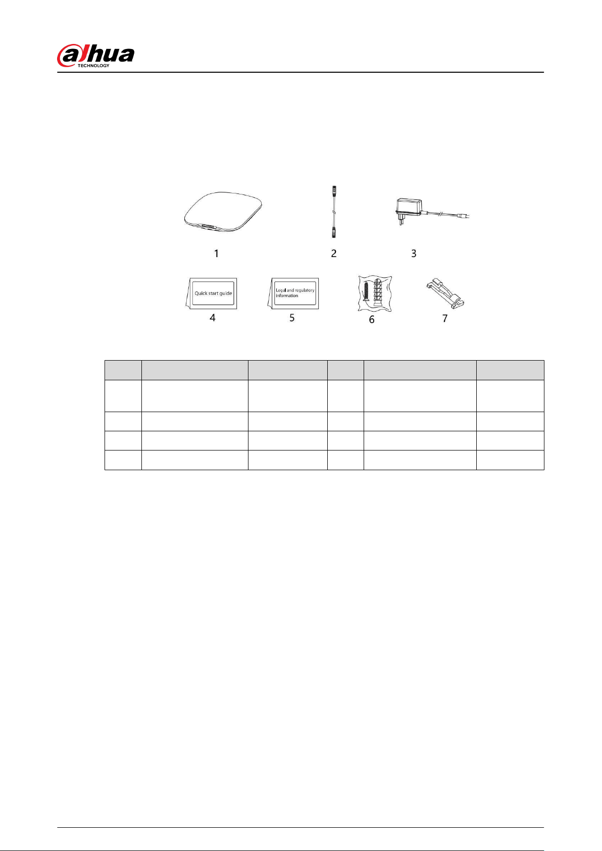
1.3 Checklist
Check the package according to the following checklist. If you nd anything damaged or lost,
contact customer service.
Figure 1-1 Checklist
Table 1-4 Checklist
No. Item Name Quantity No. Item Name Quantity
1 Alarm hub 1 5
Legal and regulatory
information
1
2 Cable 1 6 Screw package 1
3 Adapter 1 7 Wire xing clamp clip 1
4 Quick start guide 1 — — —
User's Manual
6
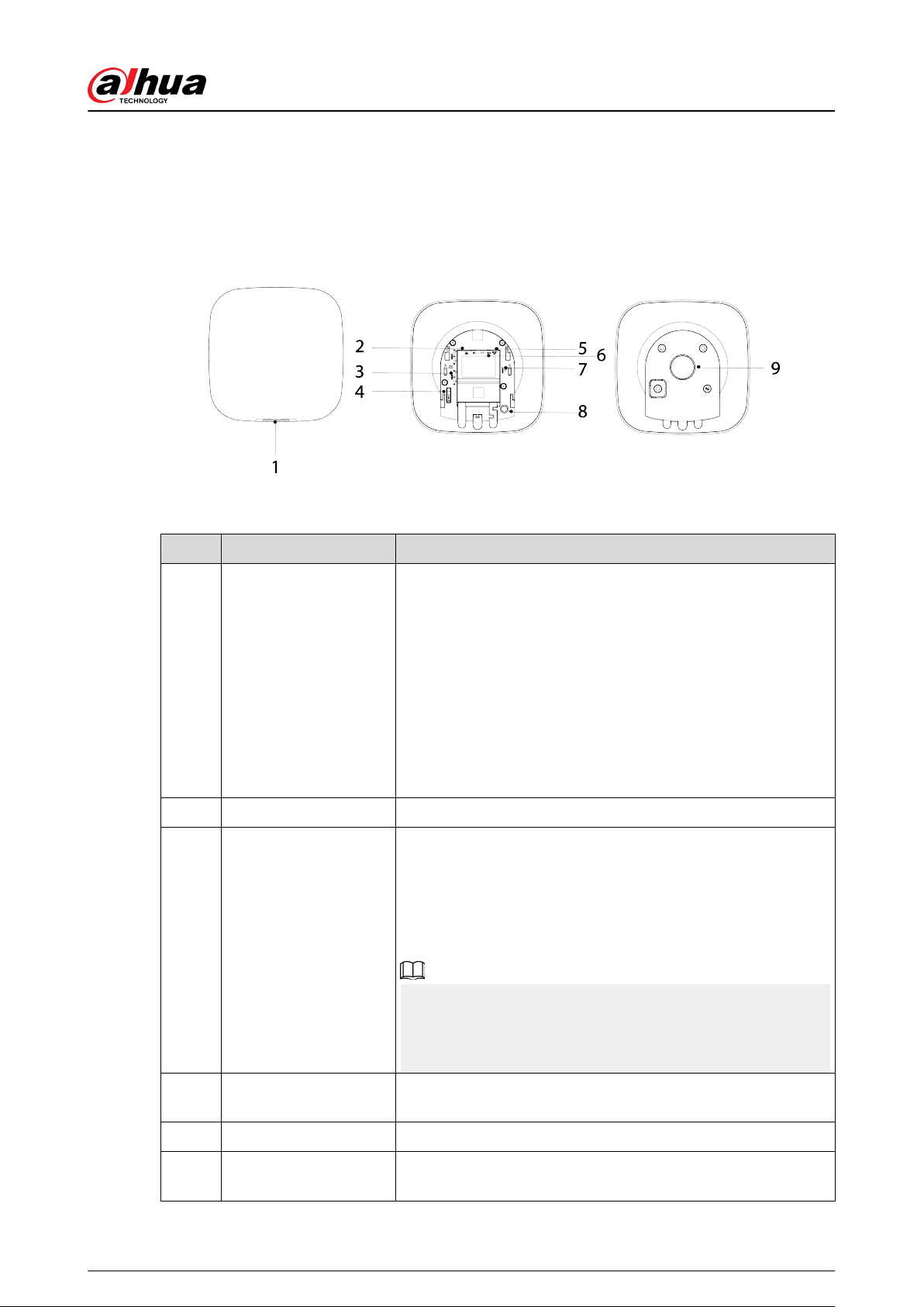
2 Design
2.1 Appearance
Figure 2-1 Appearance
Table 2-1 Structure
No. Name Description
1 Indicator
●
Flashes green slowly: Reduced sensitivity mode.
●
Flashes green: The hub starts working.
●
Solid yellow: Failed to connect to the cloud.
●
Solid green: Disarming mode.
●
Solid blue: Arming mode.
●
Flashes red: Alarm event was triggered.
●
Flashes yellow: Detected a malfunction.
●
Flashes blue: Running AP conguration or the hub is pairing
with peripherals.
●
Flashes blue quickly: Card issuing mode.
2 Ethernet cable socket Connect the hub to the Ethernet.
3 Slot for micro SIM 1/2
Install main card to the rst slot, and standby card to the
second slot.
●
Support dual SIM cards and single standby.
●
SIM cards allow the hub to use cellular data, and push alarm
notications.
●
SIM cards will not work until network conguration has
been completed.
●
SIM function is only available on select models.
4 Tamper button
When the tamper switch is released, the tamper alarm will be
triggered.
5 Power cable socket Insert power cable.
6 AP
Turn on AP, the phone will connect to the hotspot from the
hub, and then sync Wi-Fi username and password to the hub.
User's Manual
7
No. Name Description
7 Reset button
Press and hold the button for 10 seconds to restart the hub and
restore factory default settings.
8 On/o button
Press and hold the button for 2 seconds to turn on or turn o
the hub.
9 Back cover If the back cover is opened, the tamper alarm will be triggered.
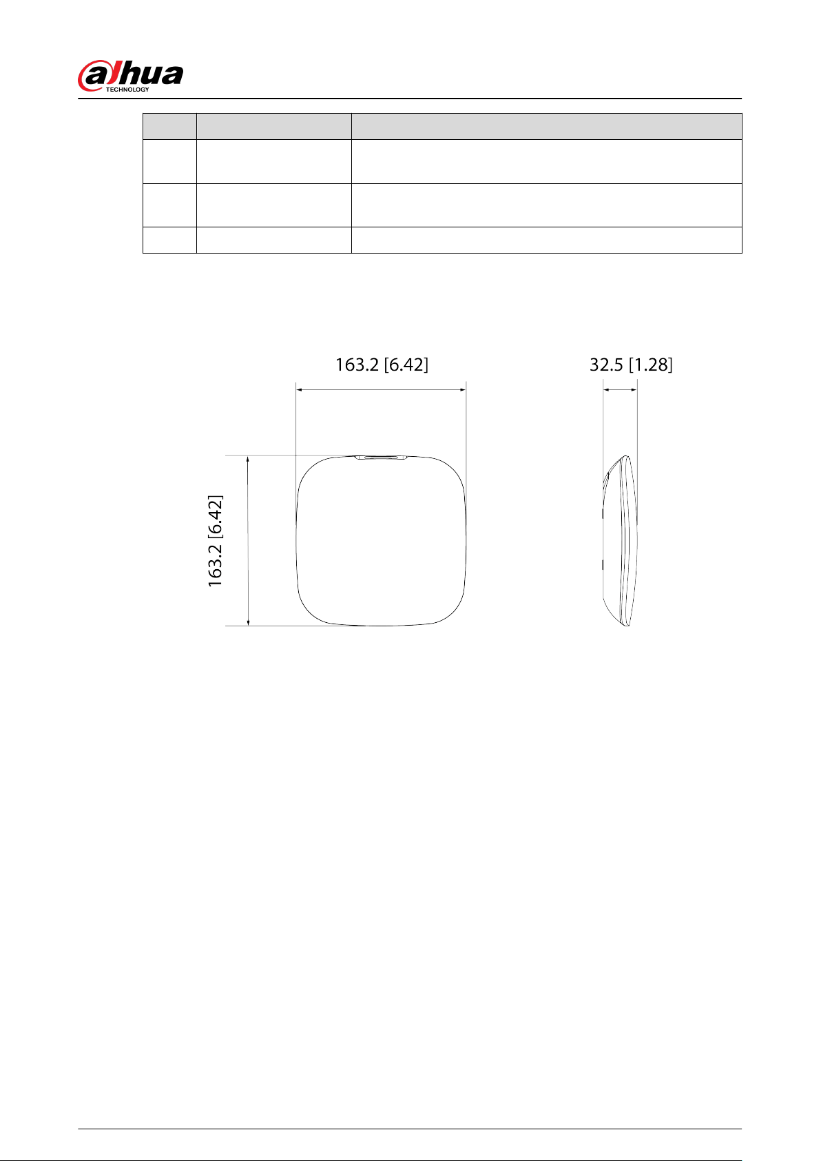
2.2 Dimensions
Figure 2-2 Dimensions (Unit: mm[inch])
User's Manual
8
3 Startup
3.1 Users
Users can only be created on the DMSS and Dolynk Care app. Classify the users into dierent roles
so that they can have dierent access levels for operating the devices.
User Access Level
Table 3-1 User access level
User Access Level
DMSS admin user L2
DMSS general user L2
Installer L3
●
Installer: Installers provide end users with operation and maintenance services. This role has to
apply for permissions from the end user (DMSS admin user) to operate the device. They can
receive permissions such as device conguration and user management.
●
DMSS admin user: The administrator user would be an end user. This role cannot be modied
and has permissions, such as device conguration and user management. The DMSS admin
users does not have permission to congure the device when installers lend the hub to them, or
when they entrust the hub to the installer.
●
DMSS general user: These are users who a DMSS admin user shares devices with through the
DMSS app. This role can be modied and only has basic permissions, such as viewing device
status, and arming and disarming rooms.
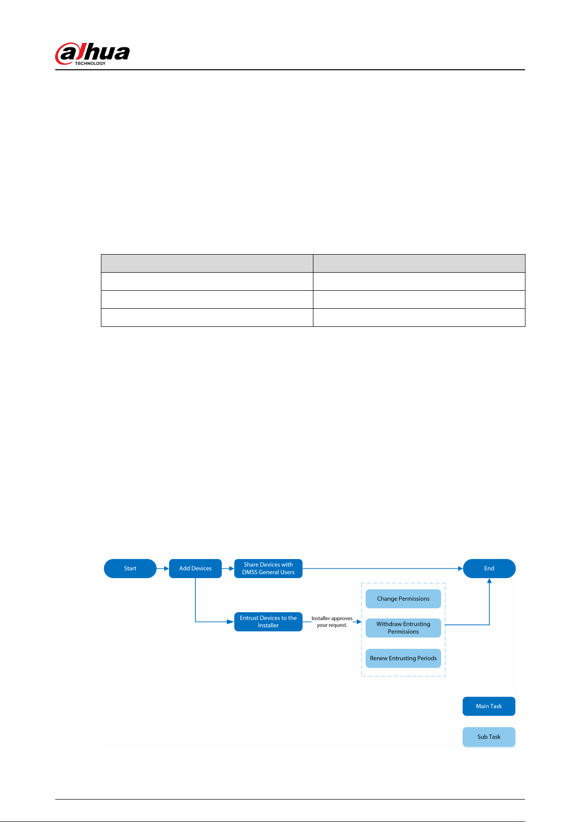
Business Flow
Following is the entrusting and sharing process on the DMSS and Dolynk Care app. Installers and
end users can follow the process to share and entrust devices.
Figure 3-1 Business ow (DMSS user)
User's Manual
9
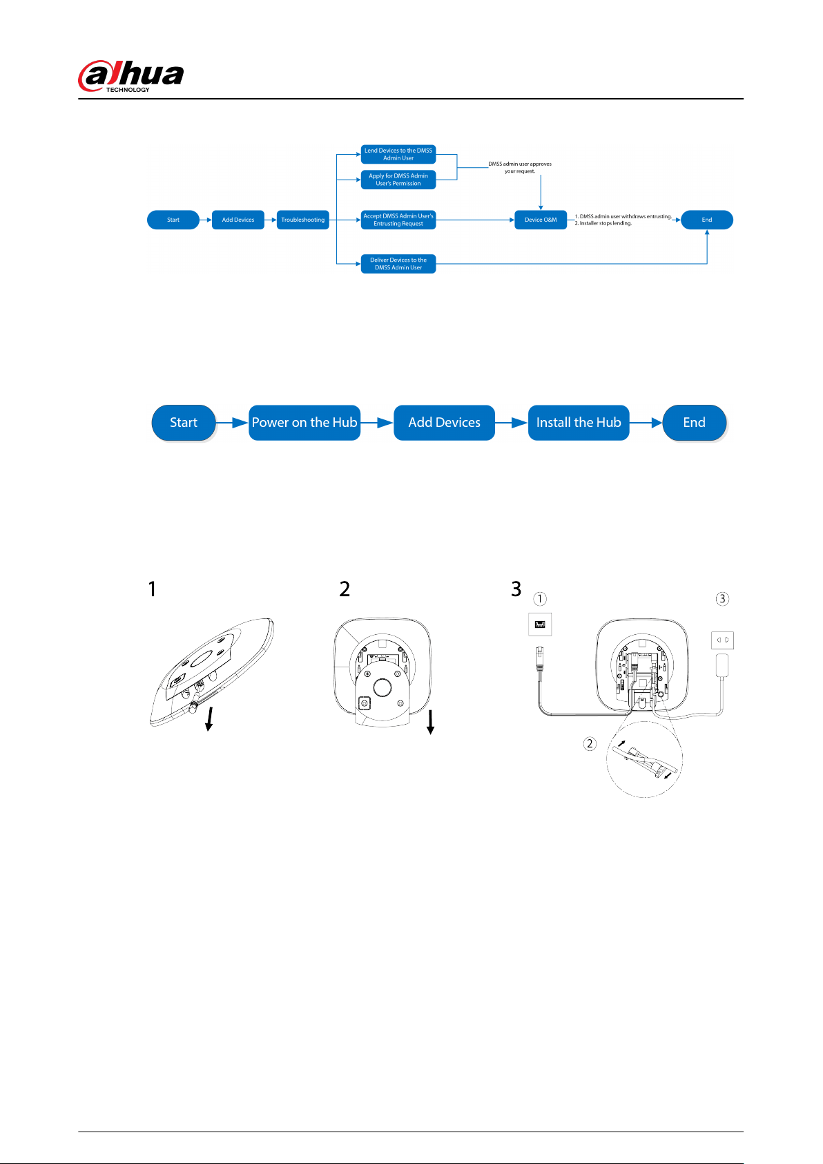
Figure 3-2 Business ow (Installer)
3.2 Operation Process
Follow the procedures below to turn on the wireless alarm system.
Figure 3-3 Operation process
Power On
Connect the hub to the Ethernet, and power on the hub.
Figure 3-4 Power on
Adding Devices
1. Add the hub to the Dolynk Care and DMSS app.
2. Add the peripherals to the hub.
Installing the Hub
We recommend using expansion screws to install the hub. Do not place the hub in the following
areas:
●
Outdoors.
●
Places close to metal objects that cause attenuation and shielding of the radio signal.
●
Places with a weak GSM signal.
User's Manual
10

●
Places close to radio interference sources that are less than 1 meter away the router and power
cables.
●
Places where the temperature and humidity exceed allowed limits.
Table 3-2 Installation items
No. Item Name No. Item Name
1 Hub 4 Mounting plate
2 M3 × 8 mm countersunk head screw 5 Expansion bolt
3 ST4 × 25 mm self-tapping screw 6 Wall
1. Conrm the position of the screw holes, and then drill them into the mounting plate.
2. Put the expansion bolts into the holes.
3. Attach the mounting plate into the wall, and then align the screw holes on the plate with the
expansion bolts.
4. Fix the mounting plate with ST4 × 25 mm self-tapping screws.
5. Put the alarm hub into the mounting plate from top to bottom.
6. Fix the alarm hub and mounting plate with M3 × 8 mm countersunk head screws.
Conguring the Hub
Congure the hub on the Dolynk Care and DMSS app.
Arming the Alarm System
You can use the keypad, keyfob and app to arm your system. After an arming command is sent to
the Dolynk Care and DMSS app, the system will check the status of the system. If the system has a
fault, you will need to choose whether to force arm it. For details on peripherals, see the user's
manual of the corresponding device.
User's Manual
11

4 Dolynk Care Operations for Installers
Dolynk Care app is designed to help installers by providing professional operation and
maintenance services for end users. It provides functions including site management, operation
and device health management, device entrusting review, and more. For details, see Dolynk Care
App User's Manual.
The gures are for reference only and might dier from the actual interface.
4.1 Logging into Dolynk Care
For rst-time use, you need to create an account. This user manual uses the operations on iOS as an
example.
Procedure
Step 1 Search for Dolynk Care in App Store to download the app.
For Android users, you can go to Google Play to search for the app.
Step 2 On your smart-phone, tap to start the app.
User's Manual
12
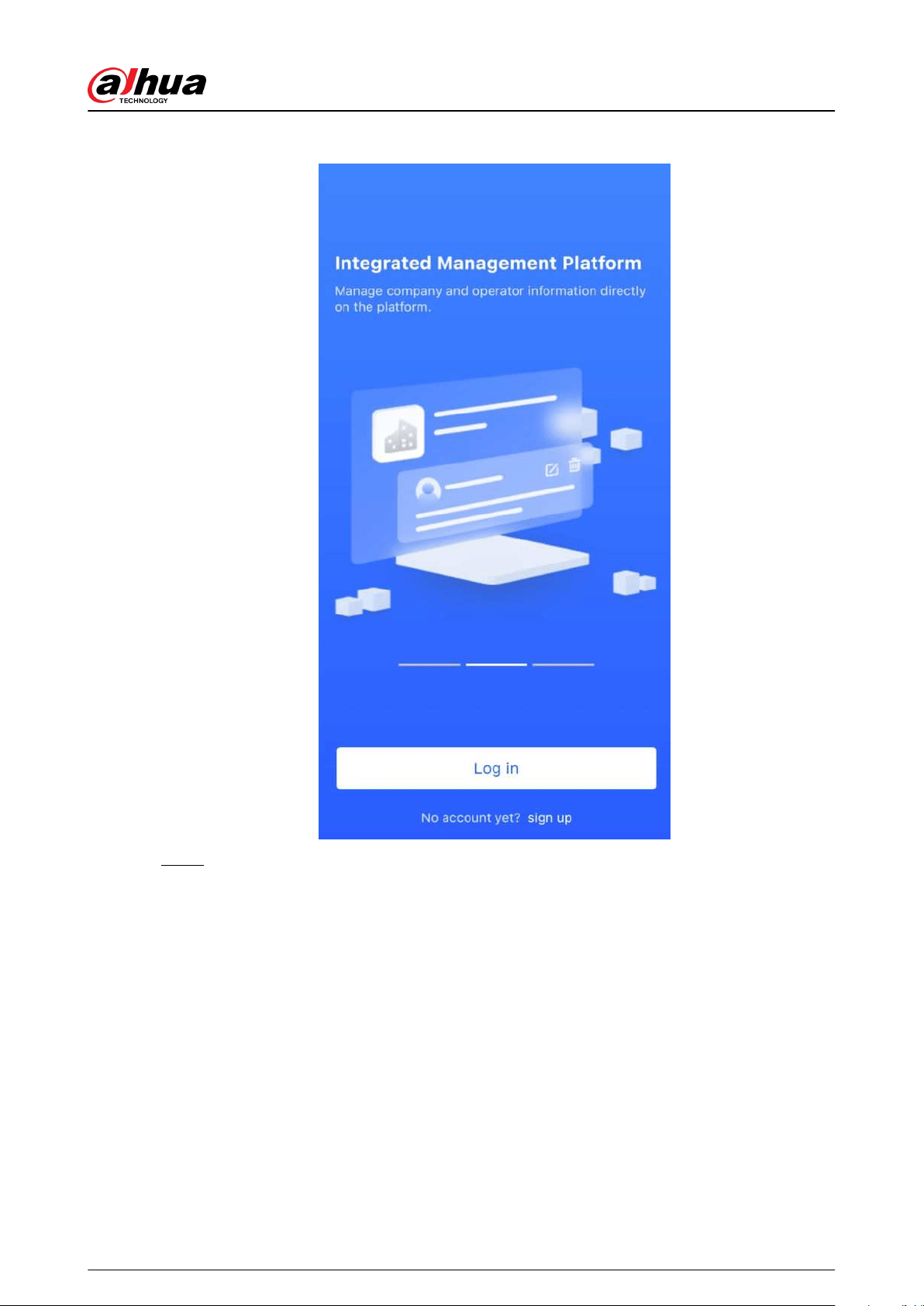
Figure 4-1 Login
Step 3 Create an account.
a. On the Login screen, tap No account yet? sign up.
b. On the Register screen, ll in the information for the required elds.
●
Company Name : Enter your company name.
●
Country Address : Select the country/ area, province/state, and city of your
company.
●
Address : Enter detailed address of your company.
●
Invitation Code : Enter the invitation code, which can be obtained from the
reseller or sales representative.
●
Email : Enter your email address.
●
Password : Enter password.
●
Verication Code : Tap Send, check your email box to receive a verication code,
and then enter the code in Verication Code.
c. Read the Privacy Policy and User Agreement, and then select the I have read and
agree to Privacy Policy and User Agreement checkbox.
d. Tap Register , and then the app returns to the Login screen.
User's Manual
13

Step 4 Enter your email address and password, and then tap Log in.
●
For new customers, account application approval is needed. It will take 1-3 days to
receive an account approval email. After that, you can log in to the app with your
account.
●
Some aliated customers do not need to be approved to register for a Dolynk Care
account. They can directly log in to the app after registration.
4.2 Adding Devices
For installers, you can add devices to the Dolynk Care app for management and maintenance.
Before adding devices, make sure that the device is connected to power and the network. You can
add alarm devices, including hubs and multiple peripherals into the app.
4.2.1 Adding the Hub
The hub can be added either in Site mode or Device mode. If you add devices in the Device
mode, you need to select a site rst. The operations for these two modes are similar. This section
uses congurations in Device mode as an example.
●
Before adding the hub, make sure that the hub is connected to power and the network.
●
Make sure that your phone has enabled Wi-Fi function.
4.2.1.1 Adding by SN or QR Code
You can add the hub by scanning the QR code of the device or manually entering device SN in the
wireless or wired network.
Procedure
Step 1 On the Home screen, tap to go to the Site screen.
User's Manual
14
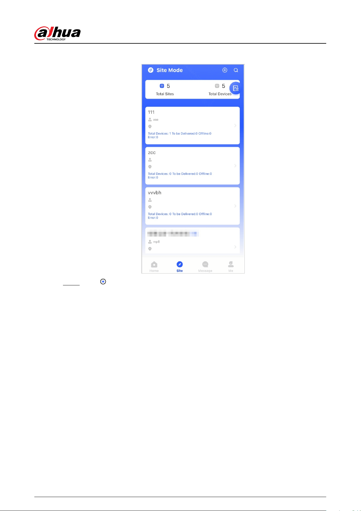
Figure 4-2 Site
Step 2 Tap to add a new site.
Enter the site information and then tap OK to create the site.
User's Manual
15

Figure 4-3 Add site
Step 3 On the Site screen that was created, tap Add Device.
Figure 4-4 Add device
Step 4 Scan device QR code, or tap Manually Add to manually enter device SN.
Step 5 Select a site, and then tap OK.
Step 6 On the Add Device screen, select a device type.
Step 7 Connect to wireless or wired network.
●
Wireless
1. Tap Wireless on the upper-right corner, and then Wireless becomes Wired.
2. Enter the password for the Wi-Fi that your phone is connected to, and then tap
Connect.
User's Manual
16

3. Follow the on-screen instructions, and then tap Next.
4. Wait for the pairing.
If failed, repeat the above procedures.
●
Wired
1. Tap Wired on the upper-right corner, and then Wired becomes Wireless.
2. Connect the device to power and the network, and then tap Next.
If failed, repeat the above procedures.
Step 8 If the hub you are adding is uninitialized, enter password and conrm it again, and then
tap Initialize the device to complete initialization.
Step 9 Tap Completed, and then you can view the device in the device list.
4.2.1.2 Adding by LAN Searching
You can search for devices and add them. Make sure that your phone and the devices are
connected to the same network.
Procedure
Step 1 On the Home screen, tap to Site screen.
Step 2 Select a site and tap Add Device to add a device.
Figure 4-5 Add a device
Step 3 Tap LAN Searching.
Step 4 On Add Device screen, enter device password, and then tap Conrm.
User's Manual
17
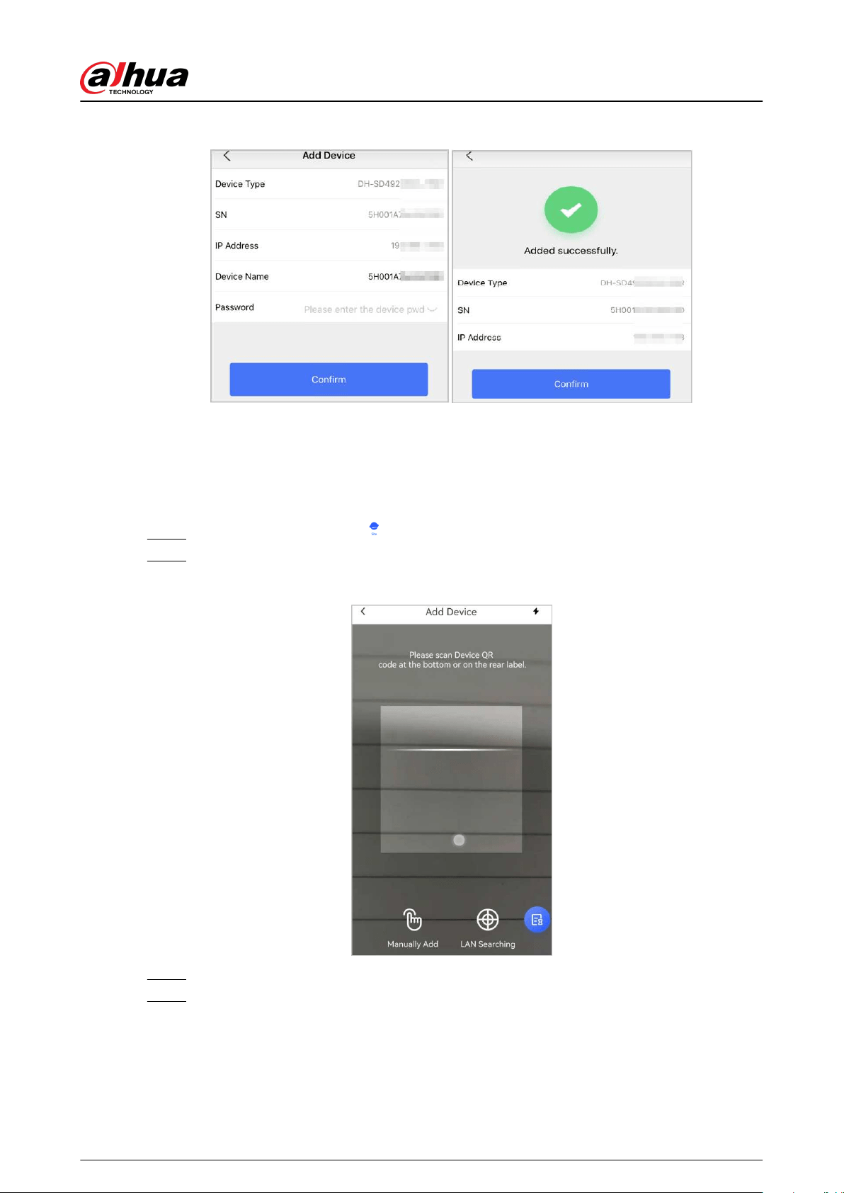
Figure 4-6 Conrm to add a device
4.2.1.3 Adding through AP Conguration
You can add the hub through AP conguration.
Procedure
Step 1 On the Home screen, tap to go to the Site screen.
Step 2 Select a site and tap Add Device to add a device.
Figure 4-7 Add a device
Step 3 Scan device QR code, or tap Manually Add to manually enter device SN.
Step 4 On the Add Device screen, select Alarm Station.
User's Manual
18
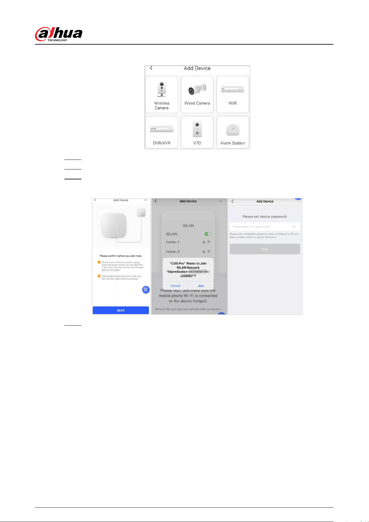
Figure 4-8 Select alarm station
Step 5 Follow the on-screen instructions and ip the DIP switch from STA to AP.
Step 6 Tap Join to connect to the device hotspot.
Step 7 Set device password to initialize the device, and then tap Next.
Figure 4-9 Add through AP conguration
Step 8 Connect to the network.
1. Select Wi-Fi.
Make sure that your phone and the device are connected to the same network.
2. Enter Wi-Fi password, and then tap Next.
3. Flip the DIP switch from AP to STA, and then tap Next.
4. Wait for device to complete network conguration.
User's Manual
19
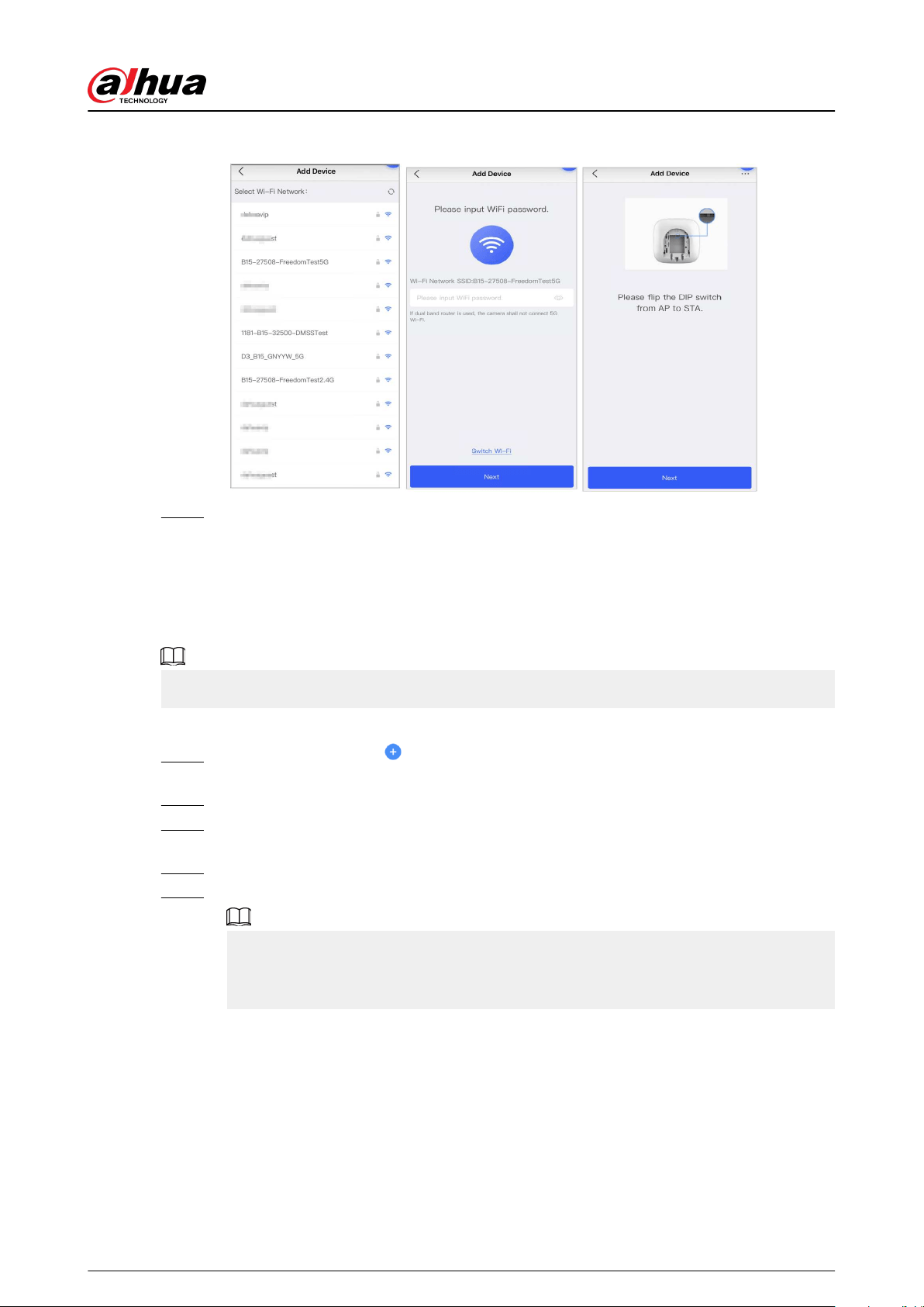
Figure 4-10 Connect to the network
Step 9 Tap Completed.
4.2.2 Adding Peripherals
You can add multiple peripherals into the hub. The section uses door detector as an example. For
details on adding peripherals, see user's manuals of respective peripherals.
Up to 6 sirens, 64 keyfobs, 4 repeaters, and 8 keypads can be added to a hub.
Procedure
Step 1 On the hub screen, tap on the upper-right corner, and then scan QR code at the
bottom of door detector.
Step 2 Tap Next.
Step 3 Follow on-screen instructions and switch the door detector to on, and then tap Next to
add it to the hub.
Step 4 Wait for the pairing.
Step 5 Customize the name of the door detector and select the area, and then tap Completed.
●
Delete the peripheral: Go to the hub screen, select the peripheral from the list, and
then swipe left to delete it.
●
Up to 32 areas can be created in a hub.
4.3 Managing Users
User's Manual
20
4.3.1 Adding DMSS Admin Users
For installer, you can add DMSS admin users by sharing entrusting devices with them or accepting
their entrusting request.
Background Information
According to EN50131 certications, the DMSS admin user does not have permission to congure
the device when installers lend the hub to them, or when they entrust the hub to the installer.
4.3.1.1 Lending the Device to the DMSS Admin Users
According to EN50131 certications, the installer can lend the hub to the DMSS admin user.
Afterwards, the installer needs to apply for permissions from the DMSS admin user, such as device
conguration, arming and disarming operations, and user management.
Make sure that the hub has not been added by other accounts.
Procedure
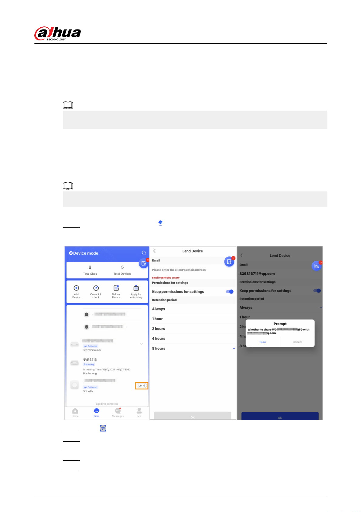
Step 1 On the Home screen, tap , and then it goes to Site screen.
Figure 4-11 Lend the hub to the DMSS admin user
Step 2 Tap on the upper-left corner to switch to Device mode.
Step 3 In the device list, select a hub, tap Lend on the right corner of the hub.
Step 4 Enter email of the DMSS admin user.
Step 5 Enable Reserve Conguration Permissions and select retention time.
Step 6 Tap Conrm.
User's Manual
21
Step 7 On the screen, tap Personal Message, you can view messages to see whether the
DMSS admin user agreed to accept your request to share with them.
A sharing message will be sent to the DMSS admin user account, and the DMSS admin
user can read the message in the DMSS app.
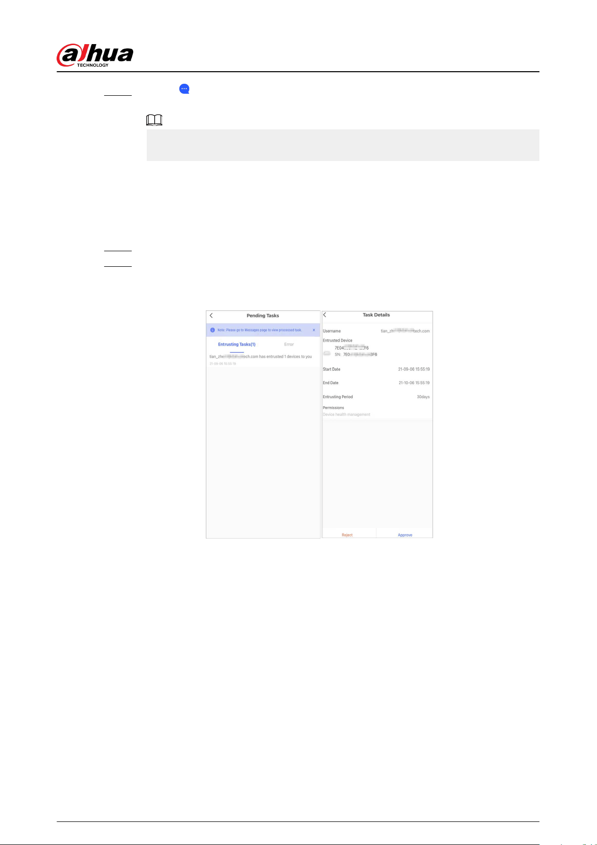
4.3.1.2 Accepting Entrusting Requests
The installer can accept DMSS admin user's entrusting request to provide O&M services for users.
Procedure
Step 1 On the Home screen, select Pending Task > Entrusting Review.
Step 2 On the Pending Task screen, select a task to view task details and handle entrusting
applications.
Figure 4-12 Handle entrusting tasks
●
To approve
1. Tap Approve , and then it goes to the Unallocated Devices screen.
2. Select devices to be allocated or tap Select all , and then tap Add to Sites.
User's Manual
22
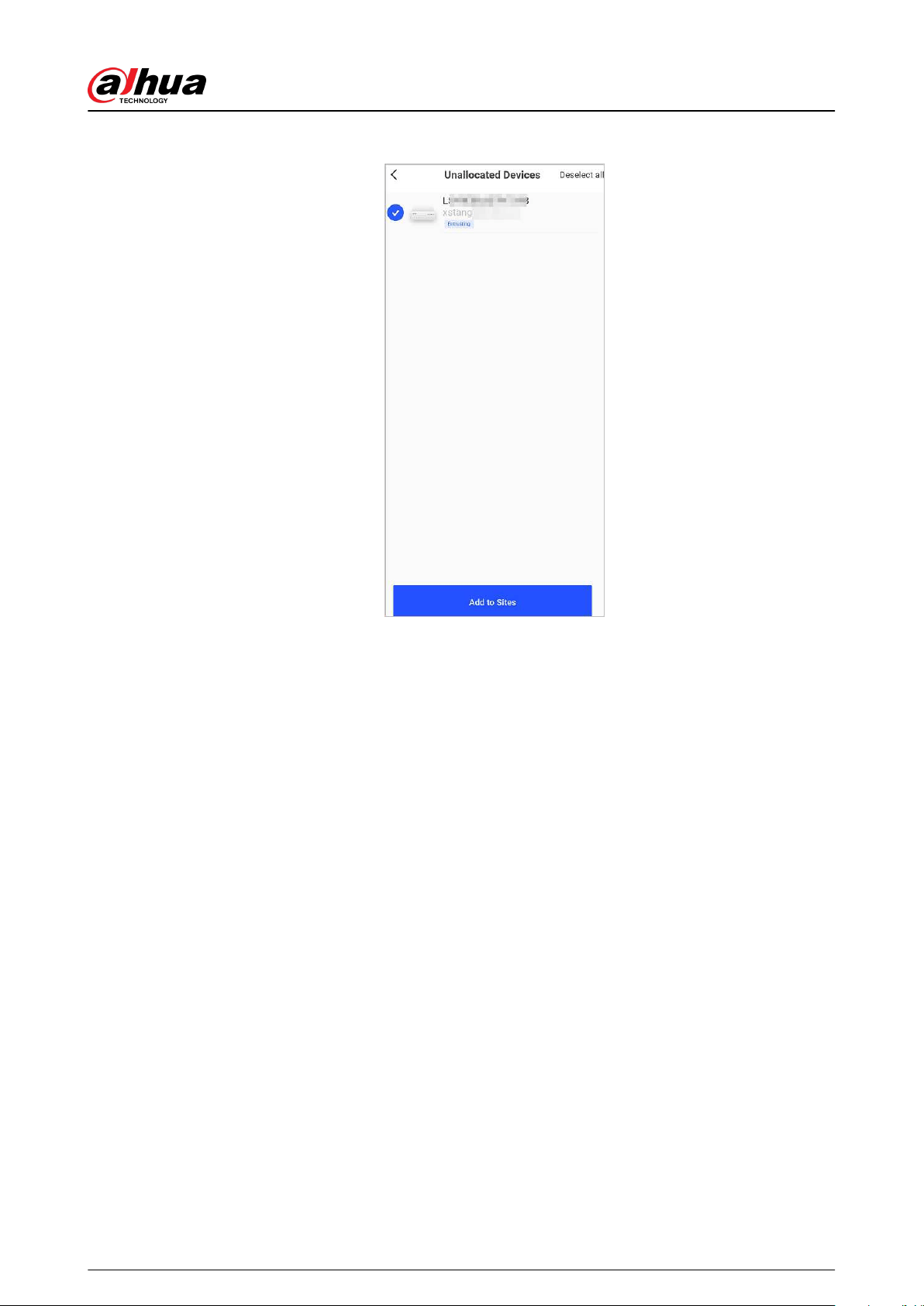
Figure 4-13 Add device to sites
3. On the Sites screen, select a site or add a new site.
4. Tap OK to conrm move this device to the selected site.
●
To reject: Tap Reject , enter reasons for rejection, and then tap Sure.
User's Manual
23
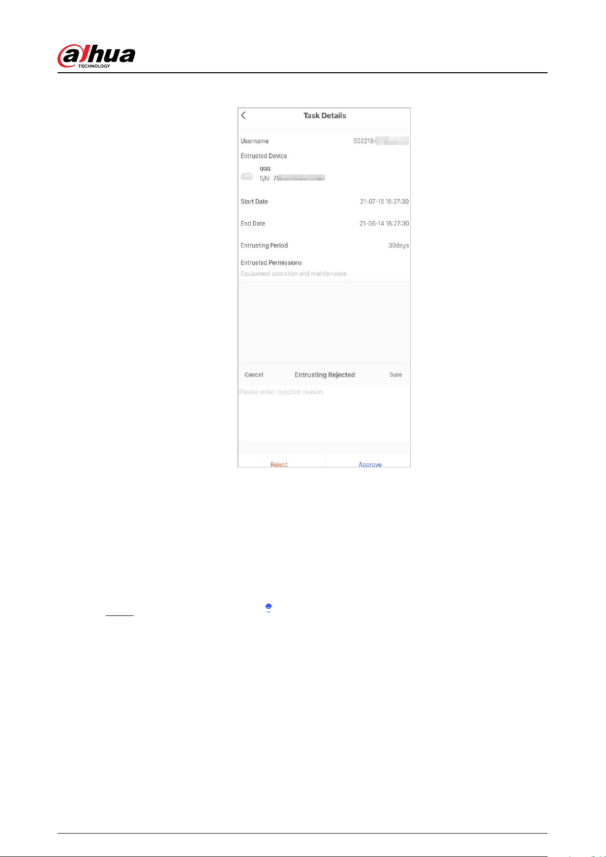
Figure 4-14 Reject
4.3.2 Deleting Users
4.3.2.1 Canceling to Lend the Devices
For installer, you can delete DMSS admin users by canceling to lend the hub to them.
Procedure
Step 1 On the Home screen, tap , and then it goes to Site screen.
User's Manual
24

Figure 4-15 Lend the hub to the DMSS admin user
Step 2 Tap on the upper-left corner to switch to Site mode.
Step 3 In the site list, select the site with the device that you lend to the DMSS admin user, then
select the hub, and then tap Cancel Lend.
The message will be sent to the DMSS admin user account, and the DMSS admin user can
read the message in the DMSS app.
4.3.2.2 Deleting Devices
For installer, you can delete DMSS admin users by deleting devices.
●
Make sure the installer has canceled to lend the devices to the DMSS admin user.
●
The installer can delete all DMSS users if DMSS admin user has shared the devices to the DMSS
general users.
Procedure
Step 1 On the Home screen, tap , and then it goes to Site screen.
Step 2 Tap on the upper-left corner to switch to Device mode.
Step 3 In the device list, select the device as needed.
Step 4 On hub screen, tap , and then tap Delete to delete the device.
User's Manual
25
4.4 Applying for DMSS Admin User's Permission
For installers, you can add the hub directly to the Dolynk Care app to provide device operation and
maintenance services for the DMSS admin users. You have time-limited permissions, including
device conguration and user management, and need to re-apply for permission upon expiry.
Procedure
Step 1 On the Home screen, tap , and then it goes to Site screen.
Step 2 Tap on the upper-left corner to switch to Device mode.
Step 3 In the device list, select the device as needed.
Step 4 On the Hub screen, select > Hub Setting, tap any parameter that you want to
congure, and then a prompt will pop up to remind you to apply for permissions from the
DMSS admin user.
Step 5 Tap Sure.
Step 6 Select permission hours, and then tap Conrm.
Step 7 On the screen, tap Personal Message to view messages to see whether the DMSS
admin user agreed to assign permissions to you.
A request message will be sent to the DMSS admin user account, and the DMSS admin
user can read the message in the DMSS app.
4.5 Delivering Devices to DMSS Admin User
After installing and conguring the devices, you can deliver devices to the DMSS admin user.
Oine and entrusted devices cannot be delivered.
The requirements of En50131certications will not be met if the installer delivers the hub to a DMSS
admin user.
Procedure
Step 1 On the Home screen, tap , and then it goes to Site screen.
Step 2 Tap on the upper-left corner to switch to Site mode.
Step 3 In the site list, select a site with devices that need to be delivered to the DMSS admin user.
Step 4 Tap , and then it goes to Deliver devices screen.
No more than 5 devices can be delivered at a time.
Step 5 Enter the DMSS admin user's emails, and then tap Sure to view deliver results. For
devices that failed to be delivered to DMSS admin user, go to the Failed screen to deliver
again.
If customers are using Imou account, then their devices will not be delivered successfully.
And a message will pop up on the Home screen stating that the account does not have
User's Manual
26
the permission. Please ask the customer to update the account on the DMSS app. For
details, see DMSS App_User's Manual.
4.6 Operation and Device Health Maintenance
Installers can provide operation and device health maintenance services, such as checking the
health status of devices, remotely conguring devices, and xing errors
4.6.1 Checking Device Health Status
You can check the online and oine status of devices in real time, and check the health status of
devices one at a time or in batches. This section uses checking in batches as an example.
Background Information
The congurations for these can be found in Site mode and Device mode. The operations for
these two modes are similar. This section uses congurations in Device mode as an example.
Procedure
Step 1 On the Home screen, tap , and then it goes to Site screen.
Step 2 Tap on the upper-left corner to switch to Device mode.
Step 3 Tap .
Step 4 Select devices you want to check, and then tap X devices selected. Start Health Check.
To select all devices, tap Select all.
Step 5 View checking results, and then tap OK.
Oine devices cannot be checked.
4.6.2 Device Basic Congurations
After adding devices, including the alarm hub and peripherals, you can view and edit general
information of the device.
Procedure
Step 1 On the Home screen, tap to go to the Site screen.
Step 2 Tap on the upper-left corner to switch to Device mode.
Step 3 In the device list, select the device as needed.
Step 4 On hub screen, tap to view and edit general information on the device.
Table 4-1 Parameter description
Parameter Description
Hub Status For details, see "4.6.2.2 Conguring the Hub".
Hub Setting For details, see "4.6.2.1 Viewing Status".
User's Manual
27

Parameter Description
Network Conguration
Tap Network Conguration to view your present network
information.
Time Zone
Tap Time Zone to select your time zone, and enable DST (daylight
saving time) if necessary.
●
Time Zone : Select the time zone in which the hub operates.
●
DST : Select date or week, and then select start time and end time.
Device Sharing
Tap Device Sharing to share the status of the hub with the other
users.
Cloud Update
Update online.
Update is not allowed when the hub is in armed status or the battery
level is low.
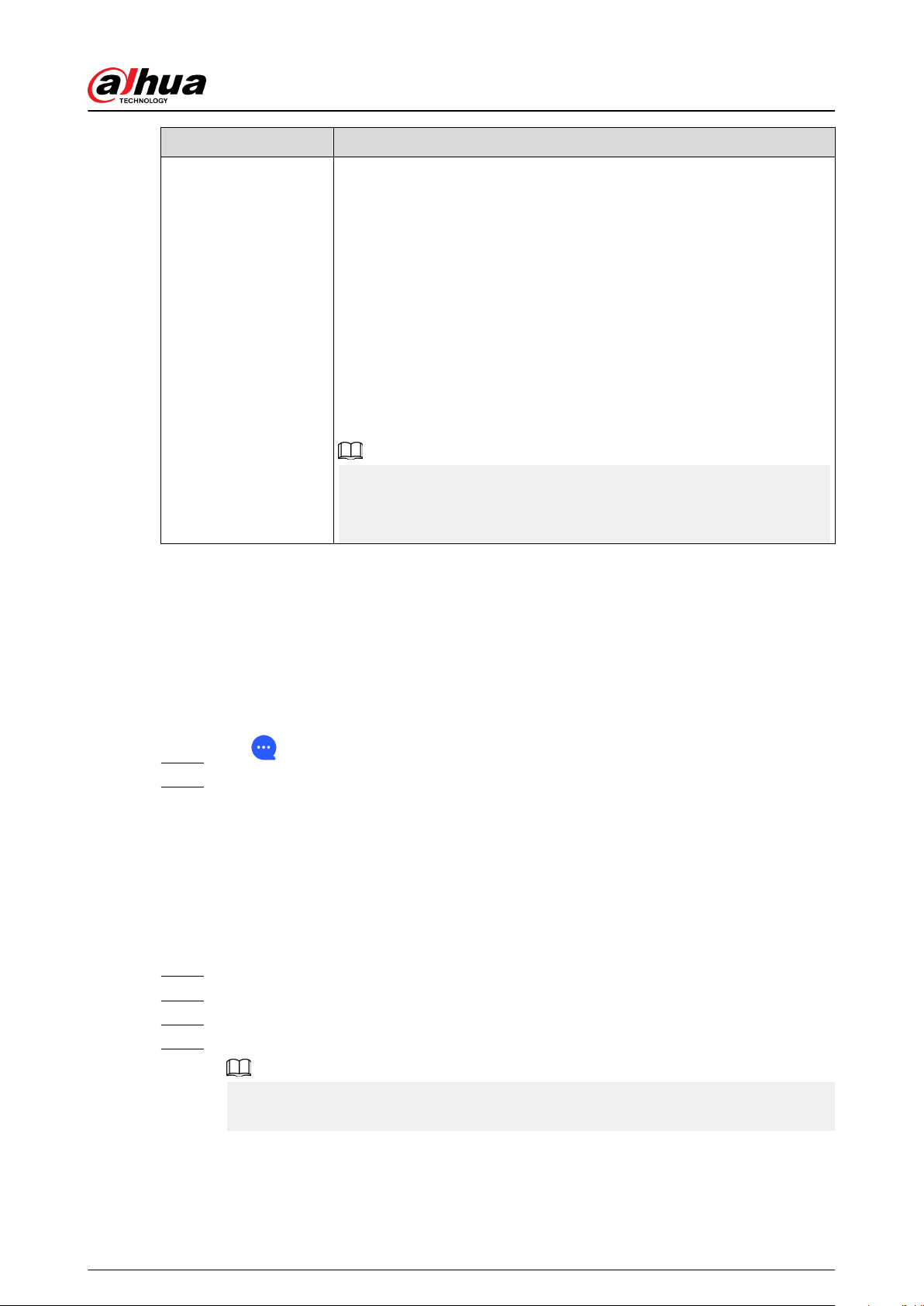
Logs
Device and app logs.
●
Device log: Select Log > Device log to view alarm logs of the
device. You can also tap
on the Device log screen to send
alarm logs to the linked email.
●
App log: Select Log > App log to view alarm logs of the Dolynk
Care. You can also tap
on the App log screen to send alarm
logs to the linked email.
User's Manual Tap User's Manual to obtain the user's manual of the alarm hub.
4.6.2.1 Viewing Status
On the Hub screen, select
> Hub Status to view the status of the hub.
Table 4-2 Status
Parameter Description
GMS/LTE Signal Strength
The signal strength of the mobile network for the active SIM card.
●
: Ultra low.
●
: Low.
●
: Moderate.
●
: High.
●
: No.
User's Manual
28
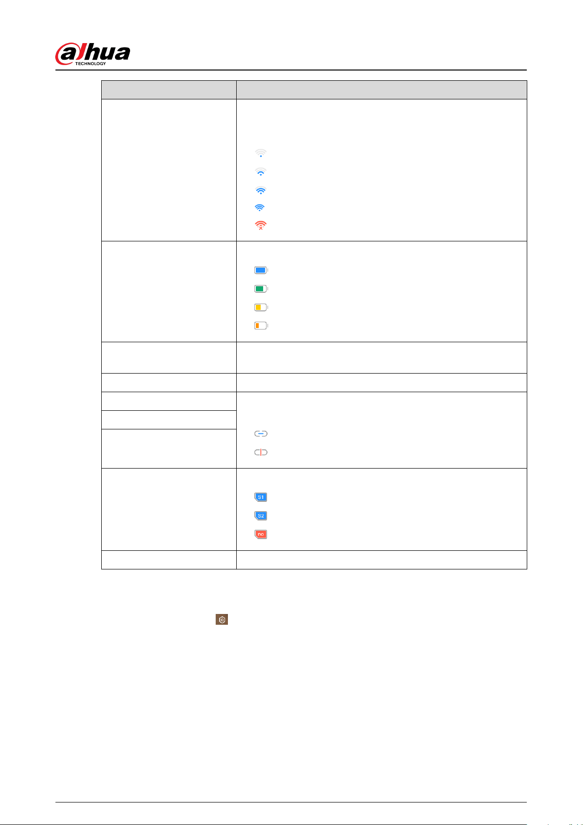
Parameter Description
Wi-Fi Signal Strength
Internet connection status of the hub via Wi-Fi. For greater
reliability, we recommend installing the hub in places with the
signal strength of at least 2 bars.
●
: Ultra low.
●
: Low.
●
: Moderate.
●
: High.
●
: No.
Battery Level
Show remaining electricity of the battery.
●
: Fully charged.
●
: Sucient.
●
: Moderate.
●
: Insucient.
Anti-tampering
The tamper mode of the peripheral, which reacts to the
detachment of the body.
Main Power Status Show main power status.
GSM/LTE Connection Status Internet connection status of the hub via SIM card, Wi-Fi, and
Ethernet.
●
: Connected.
●
: Disconnected.
Wi-Fi Connection Status
Network Cable Connection
Status
SIM Card Status
Connection status of the SIM card.
●
: SIM card 1 is active.
●
: SIM card 2 is active.
●
: No SIM card.
Program Version The program version of the hub.
4.6.2.2 Conguring the Hub
On the Hub screen, select
> Hub Setting to congure the parameters of the hub.
User's Manual
29
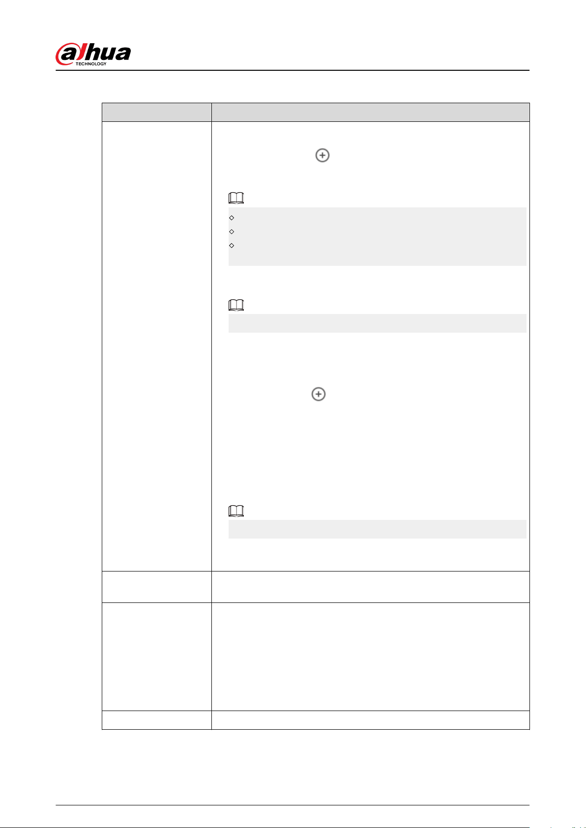
Table 4-3 Hub parameter description
Parameter Description
User Manager
You can add, modify, or delete keypad users when it is disarmed.
●
Adding Users : Tap
to add a user. Enter your username,
passcode, and duress passcode, and then select arming and
disarming permissions for the room.
Passcode and duress code must be 4 to 6 digits.
Duress passcode is optional.
Up to 32 users can be created. The rst created user is the admin
user by default. All the permissions are available to them.
●
Deleting User : Select the user, and then swipe left to delete the
user.
The admin user must be the last to be deleted.
●
Modifying User's Information : Tap the user you need to edit, and
then you can modify user's information, including username,
passcode, duress code, arming and disarming permission on the user
information page.
●
Adding Card : Tap
on the upper-right corner of the user
information page to add card for the user. Press any key to wake up
the keypad, and then place the card near the card swiping area of the
keypad to enter to the linking process within 30 seconds.
If the card information is successfully recognized, the card ID will be
displayed on the user information page, and then the keypad will
beep once. After you save the congurations, the card will have the
user's permissions.
Up to 8 cards can be linked to a user.
●
Deleting Card : Select the card, and then swipe left to delete the
card.
Global Arming/
Disarming
Arm or disarm all the detectors in all the areas with one tap.
Schedule Arming/
Disarming
Arm or disarm the areas by schedule.
●
Area : Select the area in which the hub operates.
●
Command setting : Select an armed mode as needed by tapping
Home, Away, or Disarm.
●
Time : Select the time period in which the hub operates.
●
Repeat : Copy the arming or disarming schedule.
●
Force Armed : You can arm the system when errors happen in zones.
Ringtone Setting The ringtone when entering or exiting the arming mode.
User's Manual
30
Parameter Description
LED Indicator
LED Indicator is enabled by default.
●
If LED Indicator is disabled, the LED indicator will remain o
regardless of whether the hub is functioning normally or not.
●
The function is only available when the version of the DMSS app is
1.96 or later, and the hub is V1.001.0000000.4.R.211014 or later.
Phone Number
Management
Tap Add on the upper-right corner of the page to add a phone number
to receive the event, and then select the event type that needs to send
SMS. The event types include alarm, fault, operation, and whether the
alarm is linked to the phone.
After adding, you can swipe left to test phone calls and SMS messages to
verify whether the current phone number is valid. You can also swipe
left to delete the mobile phone number.
Tap the phone number to enter the phone number editing page, and
then you can edit the number and select the event type that needs to
send SMS.
Only 2G/4G devices support this function.
Test Mode
Tap Start to test the status of the peripherals connecting to the hub in
dierent areas, and then tap Stop to complete detection.
Reduced Sensitivity
Mode
Enable Reduced Sensitivity Mode, and then the hub's transmit power
will be reduced.
The function is only available when the version of the DMSS app is 1.97
or later, and the hub is V1.001.0000000.6.R.211215 or later.
Cloud Service
Connection
Set the server-hub ping interval with the range from 150 to 900 seconds
(150 seconds by default). If the D-cloud detects that the hub's oine
duration exceeds 150 seconds, it will report the hub status to the user
through app.
The function is only available when the version of the DMSS app is 1.96
or later, and the hub is V1.001.0000000.6.R.211215 or later.
User's Manual
31
Parameter Description
Heartbeat
Congure the hub-detector ping interval. The settings determine how
frequently the hub communicates with the peripherals and how quickly
the loss of connection is detected.
●
Detector Ping Interval : The frequency of connected peripherals
operated by the hub is congured in the range of 12 seconds to 300
seconds (60 seconds by default).
The shorter the detector ping interval, the shorter the life span of the
battery.
●
Number of undelivered packets to determine connection failure :
A counter of undelivered packets is congured in the range of 3 to 60
(15 packets by default).
The smaller the number, the more frequently the oine status of
peripherals is detected and reported.
If the hub constantly loses connection with the peripherals and
cannot detect their dened heartbeats, it will report their oine
status to the system.
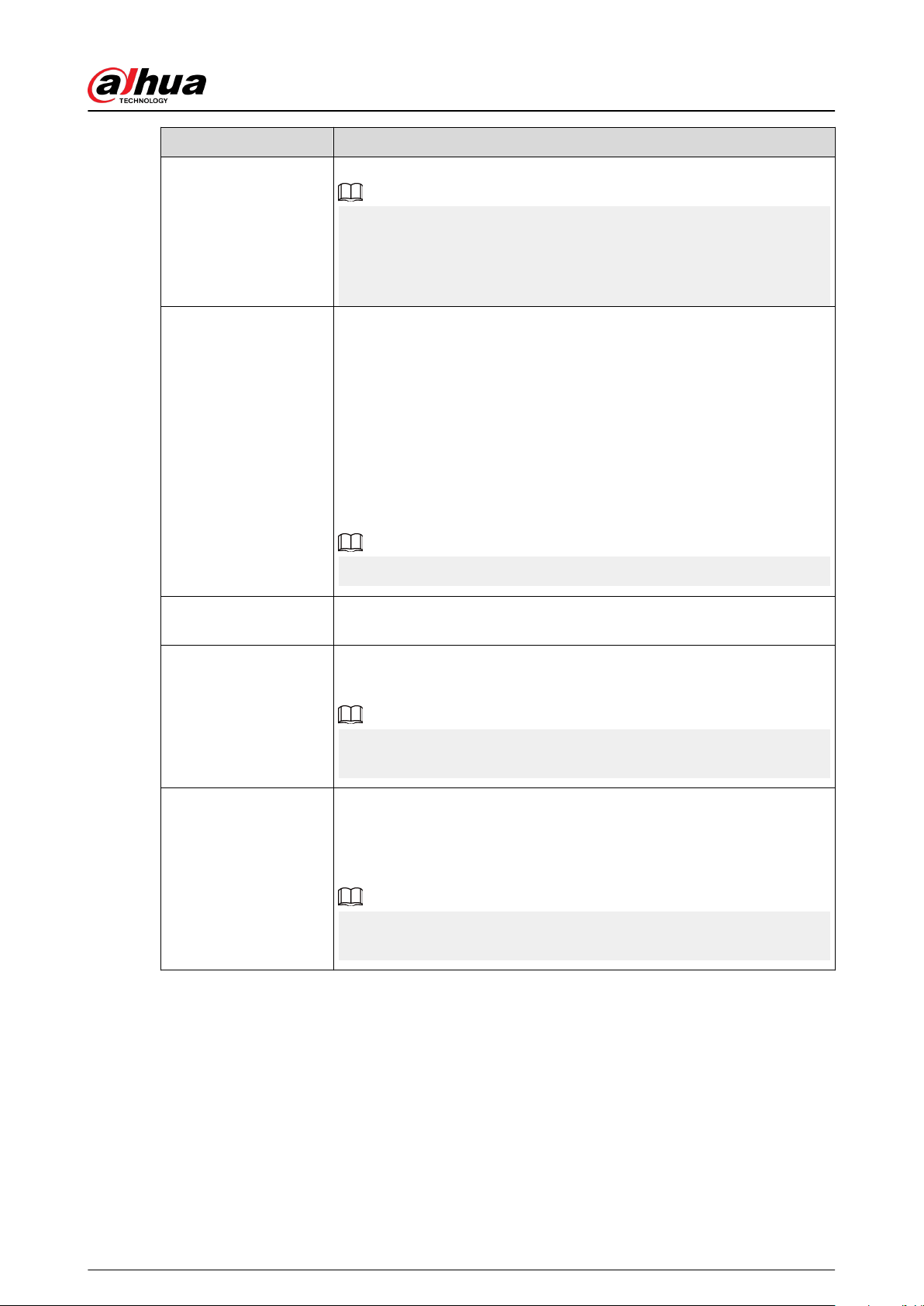
Link Siren for Tamper
●
Link Siren for Tamper : In the arming state, when the Link Siren for
Tamper is enabled, the hub will link the alarm sound.
The siren will alert when the lids of the hub and peripherals are open.
●
Always Active : Congure whether to link the alarm sound in the
disarming state. It is disabled by default. After enabling Always
Active, when the Link Siren for Tamper is enabled, the hub will link
the alarm sound in both arming and disarming state.
This is not according to EN50131-1 certications.
System Integrity Check
When enabled, the hub checks the status of all detectors before arming,
such as battery charge level, tamper incidents, and connectivity. If errors
are detected, warnings will be displayed.
●
For the keyfob, the indicator ashes green, and then turns red.
●
For the app, an alarm message pops up.
●
For the keypad, it beeps for 1 second, the arming and disarming
indicator ashes green for 2 seconds, and then it turns to the normal
status.
CMS
Enter IP address, port and device ID, and then you can register the hub
to the DSS Pro or Converter.
The function is only available when the version of the DMSS app is 1.96
or later, and the hub is V1.001.0000000.6.R.211215 or later.
User's Manual
32

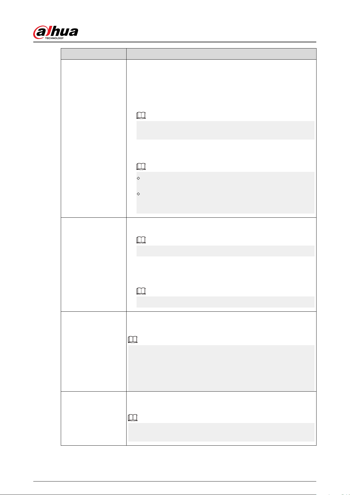
Parameter Description
Alarm Center
Enable Monitoring Station, and then set the SIA protocol parameters
for the alarm receiving center (ARC).
●
Preferred IP address : Enter the IP address and port number of the
ARC.
●
Alternative IP address : Enter the alternative IP address and port
number of the ARC.
Messages will be sent to the alternative IP address only when the
preferred IP address fails to receive the message.
If Heartbeat interval is enabled, the system will judge whether
to send the message to the preferred or alternative IP address.
●
IP Protocol : Select TCP by default.
●
Heartbeat interval : Set the heartbeat interval with the range from 0
second to 24 hours (60 seconds by default).
0 seconds means Heartbeat interval is disabled.
●
Central account : Enter the account number that created by the ARC,
which is to be used to identify the hub when the hub sends
information to the ARC.
●
Encryption : The hub uses an encryption format for information
security when you congure the ARC. AES128 is set by default.
●
Upload event : Tap
next to an event to upload it.
Alarm : Alarm message.
Error : Power failure, battery under-voltage, tamper, and oine.
Event : Prohibit the use of peripherals, add or delete peripherals,
and add or delete users.
Arm/Disarm : Message notications of arming and disarming the
system.
●
Communication Test : Supports Manual Test and Scheduled Test.
Manual Test : Manually test whether the parameters of the
preferred and alternative alarm centers are normal. If the test is
successful, the center can receive the test event.
Scheduled Test : Scheduled test is disabled by fault. After
enabling, the hub reports periodic test event regularly.
User's Manual
33
Parameter Description
Fault Check
●
Main Power Failure : It is enabled by default. After disabling, when
the main power of the hub fails, the hub will not indicate and notify.
●
Al-arm Hub Tamper : It is enabled by default. After disabling, when
the lid of the hub is open, the hub will not indicate and notify.
●
Connections to Cloud Platform : It is enabled by default. After
disabling, when the connection between the hub and cloud platform
is abnormal, the hub will not indicate and notify.
●
Wired Network and Wi-Fi Error Detection : It is enabled by default.
After disabling, when the wired network and Wi-Fi of the hub fails,
the hub will not indicate and notify.
●
RF Jamming : It is enabled by default. After disabling, when the hub
detects RF jamming, the hub will not indicate and notify, but the
event can be viewed in the log.
Disabling any of these functions will cause the system to not comply
with EN50131-1, and the error messages will not be sent related to the
disabled function.
4.6.3 Viewing Evaluations
After remotely conguring devices, and having xed errors, customers will evaluate how operators
performed in error xing and device health maintenance. The admin account can view details on
errors such as error type, the time the error occurred, suggestions and operation, the name of the
operator and ratings.
Procedure
Step 1 On screen, tap Error Notication.
Step 2 In the message list, tap a message to view message details, including customer username,
operator username, device details, error details, error xing details and rating.
4.6.4 Fixing Errors
You can x errors after abnormal devices are checked. Errors are found in two ways, including
device automatic reporting and manual checking.
Procedure
Step 1 On the Home screen, select Pending Task > Error Fixing.
Step 2 In the error list, tap an error task, and then tap Start processing.
Step 3 Fix the error according to the suggestions.
Step 4 Tap Error Fixed if the error is xed, and then wait for the customer to conrm it.
Customers will be notied of the xing status of errors. If they conrm that the error has
been xed, they will be asked to evaluate the service.
User's Manual
34
5 DMSS Operations for End Users
DMSS app provides professional security surveillance services for end users. For DMSS admin users,
you can share the hub with DMSS general users and entrust it to one enterprise. Peripherals that
come with the hub can be shared and entrusted at the same time. To share and entrust the hub by
yourself, you need to install the latest version of DMSS app.
The gures are for reference only and might dier from the actual interface.
5.1 Logging in to DMSS
The security system is congured and controlled through DMSS app. You can access to DMSS app
on iOS and Android. This section uses the operations on iOS as an example.
Make sure that you have installed the latest version of the app.
Procedure
Step 1 Search for DMSS in the app store, and then download the app.
For Android users, you can go to Google Play to download DMSS.
Step 2 On your phone, tap to start the app.
User's Manual
35
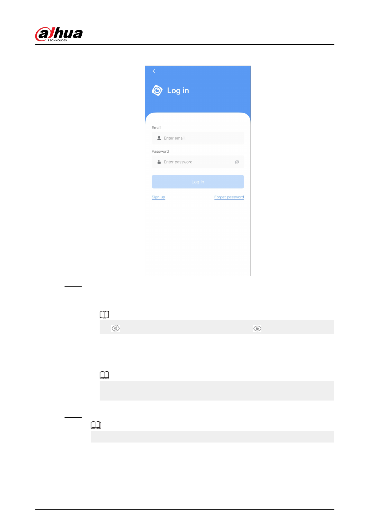
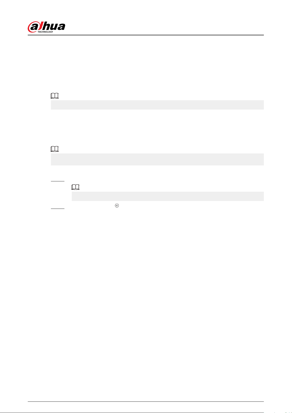
Figure 5-1 Login
Step 3 Create an account.
1. On the Login screen, tap Sign up.
2. Enter your email address and password.
Tap to show the password, and the icon will become .
3. Read the User Agreement and Privacy Policy, and then select the I have read and
agree to checkbox.
4. Tap Get verication code, check your email box for the verication code, and then
enter the code.
Use the verication code within 60 seconds of receiving it. Otherwise, the verication
code will become invalid.
5. Tap OK.
Step 4 On the Login screen, enter your email and password, and then tap Log in.
You can modify the password on the Me > Account Management > Modify Password.
User's Manual
36
5.2 Adding Devices
For end users, you can add alarm devices to DMSS app.
5.2.1 Adding the Hub
Procedure
Step 1 On the Device screen, tap , and then select SN/Scan.
Figure 5-2 Add by SN/QR code
Step 2 Add a device.
●
Scan the device QR code directly, or tap
and import the QR code picture to add a
device.
●
Tap Manually Enter SN, and then enter the device SN to manually add a device.
Step 3 Select the device type, and then tap Next.
Tap Next if the system identies the device type automatically.
Step 4 On the Add Device screen, customize the device name, enter the username and the
device password, and then tap Save.
5.2.2 Adding Peripheral
For end users, you can add multiple peripherals into the hub. The operations to add peripherals on
DMSS are the same as that on Dolynk Care app. For details, see "4.2.2 Adding Peripherals".
5.2.3 Adding IPC
Add IPCs to the hub.
Prerequisites
Make sure that the version of DMSS app is 1.99.500 or later, and the hub is V1.001.0000006.0.R.
230714 or later.
User's Manual
37

Procedure
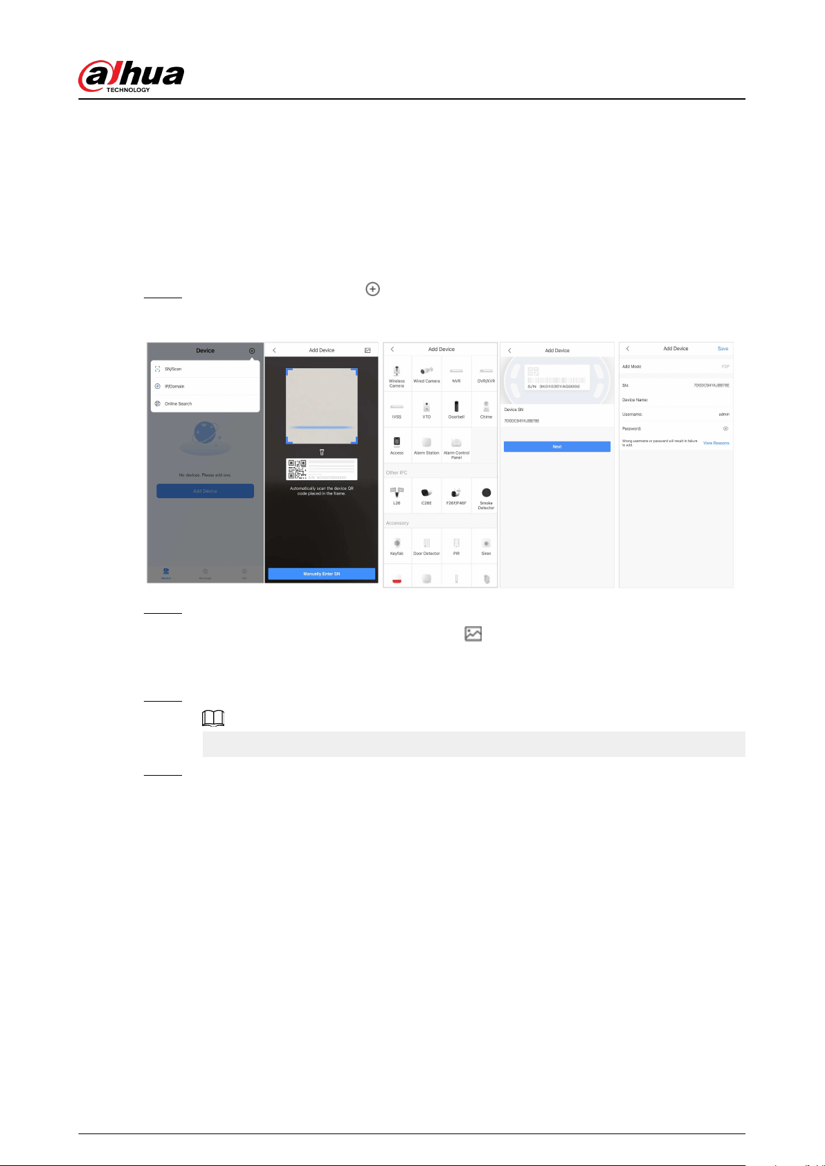
Step 1 On the hub screen, tap Peripheral , and then tap +.
Step 2 Select Add IPC.
Figure 5-3 Add IPC
Step 3 Add an IPC to the hub.
●
Manually add:
a. Congure the device name, IP address of the IPC, port number, username and the
password of the IPC, and select the area where the IPC is assigned to.
b. Tap Save.
User's Manual
38

Figure 5-4 Manually add
●
Online search:
a. Tap
to search for the IPC in the same network segment.
Figure 5-5 Online search
b. Tap Next.
c. Enter the password of the IPC and select the area where the IPC is assigned to, and
then tap Save.
User's Manual
39

Figure 5-6 Enter password
Related Operations
On the Device Details screen, congure the parameters of the IPC.
Figure 5-7 Conguring IPC
User's Manual
40

5.3 Conguring Alarm Linkage Video
Congure the alarm linkage for peripherals so that you can view video clips when the alarm is
triggered.
Prerequisites
●
Make sure that the hub is armed before you congure the alarm-video linkage.
●
Make sure that you have added peripherals to the hub.
Procedure
Step 1 On the hub screen, select a peripheral in the Peripheral list, and then tap on the
Device Details screen to congure the parameters.
Step 2 Enable Alarm-video Linkage , and then select Video Channel.
Figure 5-8 Conguration screen
Step 3 Select a video channel from the Linked Channel list, and tap Save.
User's Manual
41

Figure 5-9 Linked channel
5.4 Hub General Settings
On the Hub screen, tap
, and then you can view and edit general information of the hub.
General information of the device displayed on the DMSS app is the same as that on the Dolynk
Care app.
5.5 Network Conguration
On the General Cong of the Device Details screen, tap Network Conguration, and then you
can select network for the hub: wired network, wireless network, or cellular network.
5.5.1 Wired Network Conguration
Procedure
Step 1 Select Network Settings > Wired Network Cong.
Step 2 Congure wired network connection parameters.
Table 5-1 Description of wired network parameters
Parameter Description
DHCP
When there is a DHCP server on the network, you can enable
DHCP, and then the hub gets a dynamic IP address
automatically.
IP Address
Set the IP address manually: Set IP address, subnet mask,
default gateway, DNS and MAC address manually for the hub.
Subnet Mask
Gateway
DNS
DNS 2
MAC Address
User's Manual
42
5.5.2 Wi-Fi Network Conguration
Procedure
Step 1 Select Network Settings > Wi-Fi Network Conguration.
Step 2 Select an available Wi-Fi network in the area, and then enter the network password to
connect to the network.
5.5.3 Cellular Conguration
Procedure
Step 1 Select Network Settings > Cellular.
Step 2 Congure cellular parameters.
Table 5-2 Description of cellular parameters
Parameter Description
Cellular
Tap
next to the Cellular to enable the cellular.
Priority
Tap
next to the Priority to set the cellular as the priority
when selecting the network.
SIM 1
●
Supports dual SIM cards and single standby.
●
SIM cards allow the hub to use cellular data, and push alarm
notications.
SIM 2
APN
The Access Point Name (APN) is the name of the settings your
device reads to set up a connection for the gateway between
your carrier's cellular network and the public Internet.
Auth Mode Authentication mode of the cellular networking.
Username
The username and password of the cellular network.
Password
Dial Number The number that the hub is to call.
Mobile Data Usage View the usage of the mobile data.
Reset Statistics Reset mobile data usage to restart the count.
5.6 Managing Users
5.6.1 Adding User
For DMSS admin users, you can add both installers and DMSS general users.
User's Manual
43

5.6.1.1 Adding DMSS General User
You can go to
> Device Details > , or > Device Details > Device Sharing to share
the device. These methods are similar. This section uses sharing devices on
> Device
Sharing as an example.
Procedure
Step 1 On the Device screen, tap next to a device, and then tap Device Sharing.
Figure 5-10 Share device
Step 2 On the Device Sharing screen, share the device with the user by entering their DMSS
account or scanning their QR code.
Step 3 Select device permissions for users based on your actual need.
Step 4 Tap OK.
The account that you shared the device with will appear on the Shared User section of
the Device Sharing screen.
5.6.1.2 Adding Installer
For DMSS admin users, you can add installers by entrusting devices to them. You can entrust
devices to the installer one by one or in batches.
5.6.1.2.1 Entrusting Devices in Batches
You can entrust devices to one enterprise in batches.
Procedure
Step 1 Select Me > Batch Entrust.
User's Manual
44

Figure 5-11 Entrust devices in batches
Step 2 On the Select Device screen, select the devices to be entrusted, and then entrust those
to the enterprise. The process for entrusting multiple devices is the same as entrusting a
single device.
5.6.1.2.2 Entrusting Device One by One
Procedure
Step 1 On the Device screen, tap next to a device, and then tap Device Entrusting.
Figure 5-12 Entrust a device
Step 2 On the Entrust to Company screen, tap , and then scan the corresponding QR code
of the installer, or tap
and import the QR code picture to entrust the device to the
installer.
You can ask installers for their QR codes.
Step 3 On the Entrust to Company screen, select entrusting periods, and company viewing
permissions, and then tap OK.
●
You must select at least one viewing permission from Health Diagnosis Package and
Alarm Management.
●
Enterprise information will be automatically recognized after you scan the QR code of
the installer.
Step 4 View entrusting details on the Entrust to Company screen.
When successfully entrusted, To be Reviewed will change to Delivered.
User's Manual
45

After an entrusting request has been successfully sent, a message will pop up on the
Home screen. You need to wait for a response from the installer, which will be displayed
on the Me > Mailbox > Personal screen.
Related Operations
●
To change permissions, go to the Entrust to Company screen, and then tap Change
Permissions.
●
To withdraw entrusting permissions, go to the Entrust to Company screen, and then tap
Withdraw.
●
To renew entrusting periods, go to the Entrust to Company screen, and then tap Renew.
5.6.2 Deleting User
For DMSS admin users, you can delete both installers and DMSS general users.
5.6.2.1 Canceling Device Sharing
For DMSS admin user, you can delete DMSS general users by canceling sharing the devices with
them on the Device Sharing screen. This section uses the path of
> Device Sharing as an
example.
Procedure
Step 1 On the Device screen, tap next to a device, and then tap Device Sharing.
Step 2 In the account list of the Device Sharing screen, select an account, and tap .
Figure 5-13 Shared user
Step 3 Select Cancel Sharing , and then tap OK to cancel sharing.
5.6.2.2 Canceling Entrusting the Application
For DMSS admin users, you can delete an installer by canceling the entrusting application.
Procedure
Step 1 On the Device screen, tap next to a device, and then tap Device Entrusting.
User's Manual
46
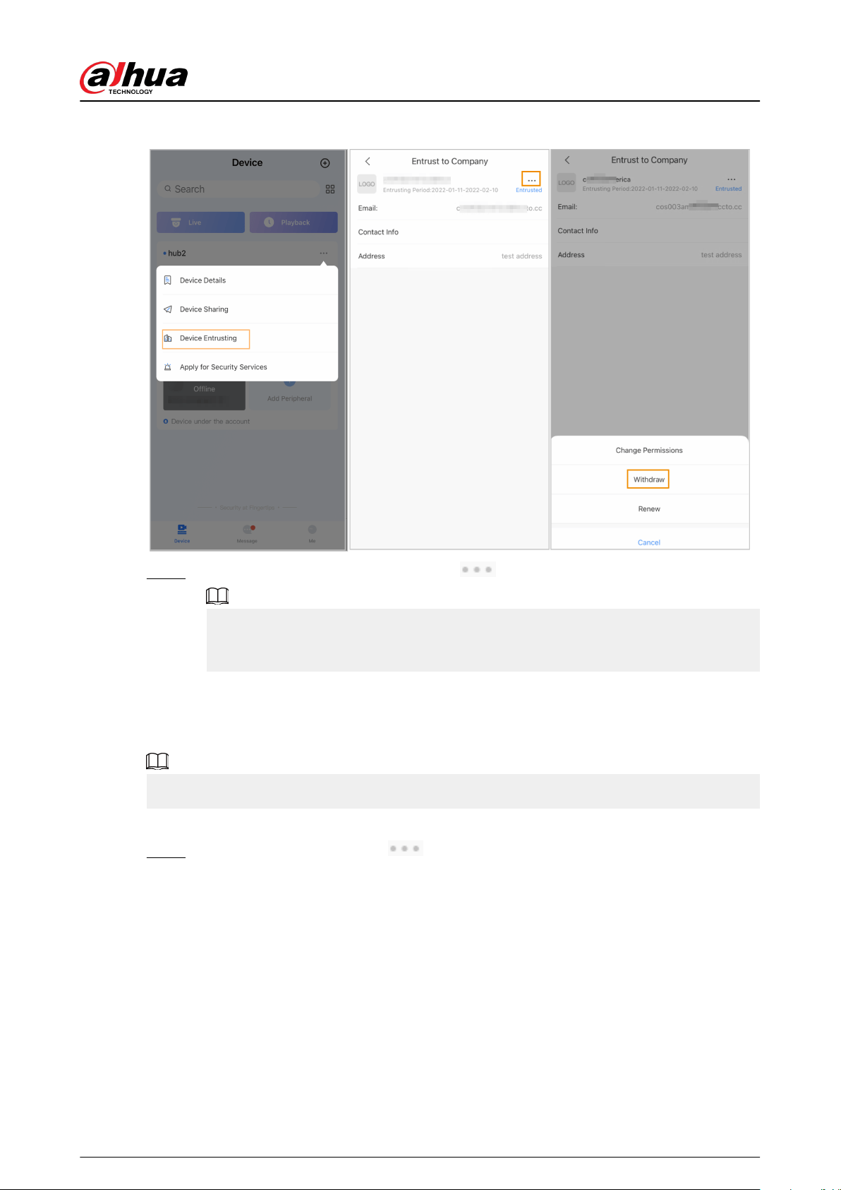
Figure 5-14 Withdraw entrusting application
Step 2 On the Device Entrusting screen, select > Withdraw, and then tap OK.
A message will be sent to the account of the installer. After the installer reads the
message and approves your request to cancel the entrusting application in Dolynk Care,
your application will be canceled.
5.6.2.3 Deleting Device
For DMSS admin user, you can delete both installers and DMSS general users by deleting devices.
DMSS admin user cannot delete an installer if the devices are shared by the installer.
Procedure
Step 1 On the Device screen, select > Device Details.
User's Manual
47
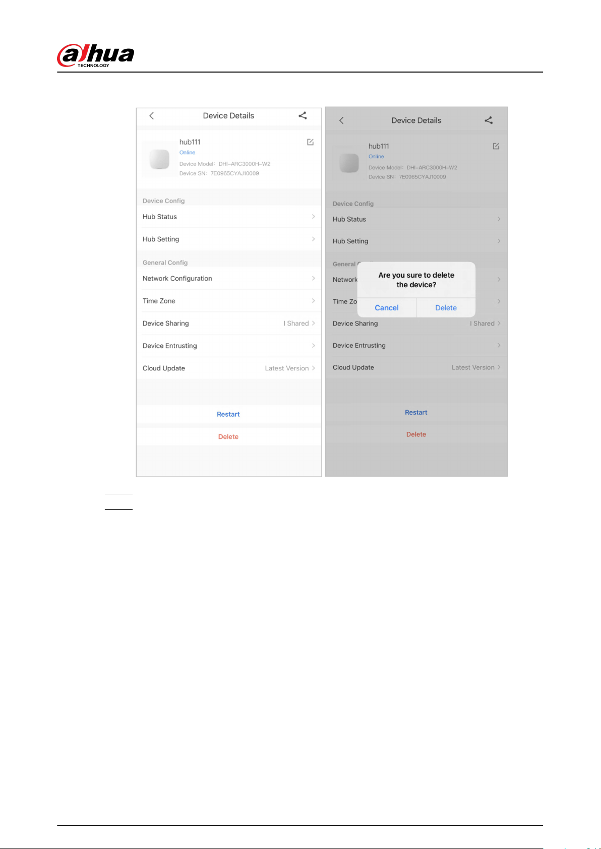
Figure 5-15 Delete the device
Step 2 On the Device Details screen, tap Delete.
Step 3 Tap Delete to delete the devices.
User's Manual
48

6 General Operations
The user in level 2 or 3 has the permission to arm and disarm the system. This section uses end
user's operation on DMSS as an example.
Prerequisites
●
Make sure that you have added a hub before performing congurations.
●
Make sure that the hub has a stable internet connection.
●
Make sure that the hub is disarmed.
Background Information
You can manage alarm hubs and peripherals, and perform operations such as arming and
disarming, conguring alarm devices.
Procedure
Step 1 On the hub screen, tap Peripheral to add the peripherals. For details on adding the
peripherals, see the user's manual of the corresponding device.
Step 2 Arm and disarm the detectors in a single area or all the areas through manual or
scheduled operations.
●
Single Arming and Disarming: Arm and disarm the detectors in a single area.
●
Global Arming and Disarming: Arm and disarm the detectors in all the areas.
●
Manual Arming and Disarming: Arm the security system through the DMSS app,
keypad or keyfob.
●
Schedule Arming and Disarming: Arm and disarm the detectors by schedule
6.1 Single Arming and Disarming
You can arm and disarm the detectors in a single area.
Procedure
Step 1 On the hub screen, tap Area.
Step 2 Tap an area, and then select from Home , Away, Disarm, and disable in the pop-up
window.
●
Home : Arm the system when inside the area of the alarm system.
●
Away : Arm the system when you leave the area of the alarm system.
●
Disarm : Turn the security system o. The opposite of arming.
●
disable : Close the current screen.
6.2 Global Arming and Disarming
Prerequisites
Make sure that you have enabled the Global Arming/Disarming function. On the hub screen,
select
> Hub Setting, and then enable Global Arming/Disarming.
Background Information
You can arm and disarm the detectors in all the areas.
Procedure
Step 1 Go to the hub screen.
Step 2 Select from Home , Away, and Disarm on the upper screen.
User's Manual
49

6.3 Manual Arming and Disarming
You can arm the security system through the DMSS app or keyfob.
●
To arm and disarm the detectors in a single area or all the areas, see "6.1 Single Arming and
Disarming", and "6.2 Global Arming and Disarming" .
●
To operate through the keyfob and keypad, you need to assign the control permissions of the
areas to the keyfob and keypad rst. For details, see the user's manual of the corresponding
keyfob and keypad.
6.4 Scheduled Arming and Disarming
You can set a schedule to arm and disarm detectors. You can congure arming plans, including
arming area, modes and periods.
Procedure
Step 1 On the hub screen, select > Hub Setting > Scheduled Arming/Disarming.
Step 2 On the Scheduled Arming/Disarming screen, tap Add, and then congure arming
plans.
●
Name : Customize a name for the arming plans.
●
Area : Select a single or multiple areas that you want to arm.
●
Command Setting : Select from Home, Away, and Disarm.
●
Time : Set an arming time.
To apply the arming time to other days, tap Repeat and select the days you want.
●
Forced Arming : Select as needed.
User's Manual
50
Appendix 1 Arming Failure Events and
Description
Appendix Table 1-1Arming failure events and description (peripherals)
No. Reason Description
1 ModuleLoss The peripheral was oine.
2 HeartError
No heartbeat packets have been sent for more than
18 minutes.
3 Alarm Alarm (24 hours).
4 Open The back cover of the device was open.
5 exOpen The back cover of the external device was open.
6 Tamper Peripheral tamper alarm was triggered.
7 LowBattery Low battery of the device was detected.
8 PriPowerLoss Peripheral main power failure was detected.
9 BatteryLoss Battery failure was detected.
10 OverVoltage Overvoltage was detected.
11 OverCurrent Overcurrent was detected.
12 OverHeat Overheat was detected.
13 FireAl-arm Fire alarm was triggered.
14 MedicalAl-arm Medical alarm was triggered.
15 SOSAl-arm SOS alarm was triggered.
16 PanicAl-arm Panic alarm was triggered.
17 GasA-larm Gas leak alarm was triggered.
18 IntrusionAl-arm Intrusion alarm was triggered.
19 HoldUpAl-arm Panic alarm was triggered.
Appendix Table 1-2Arming failure events and description (hub)
No. Reason Description
1 SOSAlert
Panic alarm can be triggered through the DMSS
app.
2 Tamper Alarm hub tamper alarm was triggered.
3 Server Connect Error The hub was oine.
4 SIAServer Connect Error
There is an error with the connection between the
hub and the SIA alarm receiving center.
5 LowBattery Low battery was detected.
6 MainLoss Main power failure was detected.
User's Manual
51

No. Reason Description
7 BatteryLoss Battery failure was detected.
8 NoGSM 2G/4G module errors was detected.
9 ATS Fault Alarm transmission system fault was detected.
10 Cellular Network ATP Fault
Alarm transmission path fault (Cellular network
failure) was detected.
11
Wired Network/Wi-Fi ATP
Fault
Alarm transmission path fault (Wireless or Wi-Fi
network failure) was detected.
User's Manual
52
Appendix 2 SIA Event Codes and Description
Appendix Table 2-1SIA event codes and description
No. Event CID Code Description
1 Motion Detected
130 Burglary Alarm.
133 24 Hour (Safe) Alarm.
134 Entry/Exit Alarm.
2
Opening Action
Detected/Closing
Action Detected
130 Burglary Alarm.
133 24 Hour (Safe) Alarm.
134 Entry/Exit Alarm.
3
External Contact was
Opened/External
Contact was Closed
130 Burglary Alarm.
133 24 Hour (Safe) Alarm.
134 Entry/Exit Alarm.
4 Duress Alarm 121 Duress Alarm.
5
Panic Button was
Pressed
122 Panic Alarm (Silent).
123 Panic Alarm (Udible).
6 Intrusion Alarm
130 Burglary Alarm.
133 24 Hour (Safe) Alarm.
134 Entry/Exit Alarm.
7 Fire Alarm 110 Fire Alarm.
8 Gas Leak Detected 151 Gas Detected Alarm.
9
Medical Alarm Button
was Pressed
100 Medical Alarm.
10
Hold-up Button was
Pressed
122 Panic Alarm (Silent).
123 Panic Alarm (Udible).
11 Glass Break Detected
130 Burglary Alarm.
133 24 Hour (Safe) Alarm.
134 Entry/Exit Alarm.
12 Tilt Detected
130 Burglary Alarm.
133 24 Hour (Safe) Alarm.
134 Entry/Exit Alarm.
13 Shock Detected
130 Burglary Alarm.
133 24 Hour (Safe) Alarm.
134 Entry/Exit Alarm.
14
Tripwire Alarm/
Tripwire Alarm Stopped
131 Perimeter Alarm
User's Manual
53

No. Event CID Code Description
15
Control Panel Lid was
Opened/Control Panel
Lid was Closed
137 Tamper.
16
Peripheral Lid was
Opened/Peripheral Lid
was Closed
137 Sensor tamper.
17
External Lid was
Opened/External Lid
was Closed
137 Sensor tamper.
18
Water Leak Detected /
Water Leak Stopped
154 Water leakage.
19
Low Battery/Battery
Level Restored
302 Low system battery.
20
Battery Fault/Battery
Restored
311 Battery missing/dead.
21
Main Power Failure/
Main Power Restored
301 AC loss.
22 RF Jamming 344 RF Receiver jam detect.
23
Alarm Transmission
System Fault/Restored
350 Communication trouble.
24
Alarm Transmission
Path:Wire Network/Wi-
Fi Fault/Restored
350 Communication trouble.
25
Alarm Transmission
Path: Cellular Network
Fault/Restored
350 Communication trouble.
26
Peripheral Connection
Lost/Peripheral
Connection Restored
355 Loss of supervision - RF.
27
Hub is Oine/ Hub is
Online
356 Loss of central polling
28
Peripheral Low Battery/
Peripheral Battery Level
Restored
302 Low system battery.
29
Peripheral Battery
Fault/Peripheral Battery
Restored
311 Battery missing/dead.
30
Peripheral Main Power
Failure/Peripheral Main
Power Restored
301 AC Loss.
31
RF-HD Connection
Failed/RF-HD
Connection Restored
354 Failure to communicate event.
User's Manual
54

No. Event CID Code Description
32
Device Locked and
Unlocked
501 Access reader disable.
33
Overvoltage Protection
Triggered /Overvoltage
Protection Restored
319 Power supply overvoltage.
34
Overcurrent Protection
Triggered Overcurrent
Protection Restored
312 Power supply overcurrent.
35
Overheat Protection
Triggered/Overheat
Protection Restored
318 Power supply overheat.
36
High Temperature/
Normal Temperature
158 High temp.
37
Low Temperature/
Normal Temperature
159 Low temp.
38 Armed
400 (App) Open/Close.
401 (Keypad) O/C by user.
403 (Scheduled
arming)
Automatic O/C.
407 (Keyfob) Remote arm/disarm.
408 (Global arming) Quick arm.
39 Disarmed
400 (App) Open/Close.
401 (Keypad) O/C by user.
403 (Scheduled
arming)
Automatic O/C.
407 (Keyfob) Remote arm/disarm.
40 Home Mode Activated 441 Armed STAY.
41 Unsuccessful Arming
454 (Arming failure) Failed to close.
455 (Scheduled arming
failure)
Auto-arm failed.
457 (Exit delay arming
failure)
Exit error (user).
42 Armed with Faults 450 Exception O/C.
43
Temporarily
Deactivated/
Reactivated
502 Temporarily deactivated.
44
Temporarily Disabled
Notications for the
Lid /Enabled
Notications for the Lid
503 Temporarily disabled.
45
Test Report was
Manually Triggered
601 Manual trigger test report.
User's Manual
55

No. Event CID Code Description
46 Periodic Test Report 602 Periodic test report.
User's Manual
56

Appendix 3 Cybersecurity Recommendations
Cybersecurity is more than just a buzzword: it’s something that pertains to every device that is
connected to the internet. IP video surveillance is not immune to cyber risks, but taking basic steps
toward protecting and strengthening networks and networked appliances will make them less
susceptible to attacks. Below are some tips and recommendations from Dahua on how to create a
more secured security system.
Mandatory actions to be taken for basic device network security:
1. Use Strong Passwords
Please refer to the following suggestions to set passwords:
●
The length should not be less than 8 characters.
●
Include at least two types of characters; character types include upper and lower case letters,
numbers and symbols.
●
Do not contain the account name or the account name in reverse order.
●
Do not use continuous characters, such as 123, abc, etc.
●
Do not use overlapped characters, such as 111, aaa, etc.
2. Update Firmware and Client Software in Time
●
According to the standard procedure in Tech-industry, we recommend to keep your device
(such as NVR, DVR, IP camera, etc.) rmware up-to-date to ensure the system is equipped
with the latest security patches and xes. When the device is connected to the public
network, it is recommended to enable the “auto-check for updates” function to obtain timely
information of rmware updates released by the manufacturer.
●
We suggest that you download and use the latest version of client software.
"Nice to have" recommendations to improve your device network security:
1. Physical Protection
We suggest that you perform physical protection to device, especially storage devices. For
example, place the device in a special computer room and cabinet, and implement well-done
access control permission and key management to prevent unauthorized personnel from
carrying out physical contacts such as damaging hardware, unauthorized connection of
removable device (such as USB ash disk, serial port), etc.
2. Change Passwords Regularly
We suggest that you change passwords regularly to reduce the risk of being guessed or cracked.
3. Set and Update Passwords Reset Information Timely
The device supports password reset function. Please set up related information for password
reset in time, including the end user’s mailbox and password protection questions. If the
information changes, please modify it in time. When setting password protection questions, it is
suggested not to use those that can be easily guessed.
4. Enable Account Lock
The account lock feature is enabled by default, and we recommend you to keep it on to
guarantee the account security. If an attacker attempts to log in with the wrong password
several times, the corresponding account and the source IP address will be locked.
5. Change Default HTTP and Other Service Ports
We suggest you to change default HTTP and other service ports into any set of numbers
between 1024–65535, reducing the risk of outsiders being able to guess which ports you are
using.
6. Enable HTTPS
We suggest you to enable HTTPS, so that you visit Web service through a secure communication
channel.
User's Manual
57

7. MAC Address Binding
We recommend you to bind the IP and MAC address of the gateway to the device, thus reducing
the risk of ARP spoong.
8. Assign Accounts and Privileges Reasonably
According to business and management requirements, reasonably add users and assign a
minimum set of permissions to them.
9. Disable Unnecessary Services and Choose Secure Modes
If not needed, it is recommended to turn o some services such as SNMP, SMTP, UPnP, etc., to
reduce risks.
If necessary, it is highly recommended that you use safe modes, including but not limited to the
following services:
●
SNMP: Choose SNMP v3, and set up strong encryption passwords and authentication
passwords.
●
SMTP: Choose TLS to access mailbox server.
●
FTP: Choose SFTP, and set up strong passwords.
●
AP hotspot: Choose WPA2-PSK encryption mode, and set up strong passwords.
10.Audio and Video Encrypted Transmission
If your audio and video data contents are very important or sensitive, we recommend that you
use encrypted transmission function, to reduce the risk of audio and video data being stolen
during transmission.
Reminder: encrypted transmission will cause some loss in transmission eciency.
11.Secure Auditing
●
Check online users: we suggest that you check online users regularly to see if the device is
logged in without authorization.
●
Check device log: By viewing the logs, you can know the IP addresses that were used to log
in to your devices and their key operations.
12.Network Log
Due to the limited storage capacity of the device, the stored log is limited. If you need to save
the log for a long time, it is recommended that you enable the network log function to ensure
that the critical logs are synchronized to the network log server for tracing.
13.Construct a Safe Network Environment
In order to better ensure the safety of device and reduce potential cyber risks, we recommend:
●
Disable the port mapping function of the router to avoid direct access to the intranet devices
from external network.
●
The network should be partitioned and isolated according to the actual network needs. If
there are no communication requirements between two sub networks, it is suggested to use
VLAN, network GAP and other technologies to partition the network, so as to achieve the
network isolation eect.
●
Establish the 802.1x access authentication system to reduce the risk of unauthorized access
to private networks.
●
Enable IP/MAC address ltering function to limit the range of hosts allowed to access the
device.
More information
Please visit Dahua ocial website security emergency response center for security announcements
and the latest security recommendations.
User's Manual
58