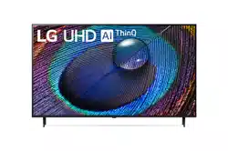
LG Electronics 43UR9000PUA 43 Inch Class Ur9000 Series Led 4k Uhd Smart Webos 23 W/ Thinq Ai Tv

User Manual

For 43UR9000PUA.

PDF File Manual, 29 pages, Read Online | Download pdf file

43UR9000PUA photo
background
ENGLISH_index
Safety and Reference
OWNER’S MANUAL
www.lg.com
Copyright © 2023 LG Electronics Inc.
All Rights Reserved.
LED TV*
Please read this manual carefully
before operating your set and retain it
for future reference.
* LG LED TV applies LCD screen with LED backlights.
The model and serial number of the product are
located on the back and on one side of the product.
Record them below in case you ever need service.
Model
Serial No.
Printed in Korea
*MFL719464322301REV01*
Supplier`s Declaration of
Conformity
Trade Name LG
Responsible
Party
LG Electronics USA,
Inc.
Address 111 Sylvan Avenue,
North Building,
Englewood Cliffs,
NJ07632
E-mail lg.environmental@
lge.com
LG Customer Information Center
For inquires or comments, visit www.
lg.com or call;
1-800-243-0000
USA, Consumer
User
1-888-865-3026
USA, Commercial
User
1-888-542-2623 CANADA
Register your product Online!
www.lg.com
43QNED75ARA
43QNED75URA
50QNED75ARA
50QNED75URA
50QNED80ARA
50QNED80URA
55QNED75ARA
55QNED75URA
55QNED80ARA
55QNED80URA
55QNED85ARA
55QNED85URA
65QNED75ARA
65QNED75URA
65QNED80ARA
65QNED80URA
65QNED85ARA
65QNED85URA
75QNED75ARA
75QNED75URA
75QNED80ARA
75QNED80URA
75QNED85ARA
75QNED85URA
86QNED80ARA
86QNED80URA
86QNED85ARA
86QNED85URA
43UR8000AUA
43UR8000AUB
43UR9000PUA
50UR8000AUA
50UR8000AUB
50UR9000PUA
50UR9000PUB
55UR8000AUA
55UR8000AUB
55UR9000PUA
65UR8000AUA
65UR8000AUB
65UR9000PUA
70UR8000AUA
70UR8000AUB
75UR8000AUA
75UR8000AUB
75UR9000PUA
75UR9000PUB
86UR8000AUA
86UR8000AUB
86UR8000PUB
86UR9000PUA
Loading page 2...
Loading page 3...
Loading page 4...
Loading page 5...
Loading page 6...
Loading page 7...
Loading page 8...
Loading page 9...
Loading page 10...
Loading page 11...
Loading page 12...
Loading page 13...
Loading page 14...
Loading page 15...
Loading page 16...
Loading page 17...
Loading page 18...
Loading page 19...
Loading page 20...
Loading page 21...
Loading page 22...
Loading page 23...
Loading page 24...
Loading page 25...
Loading page 26...
Loading page 27...
Loading page 28...
Loading page 29...

Other documents for LG Electronics 43UR9000PUA

The following documents are available:
User Manual Specification Photos

Specifications

User Manual - Transcript

  • Page 1 - English - : ENGLISHindex Safety and Reference OWNERS MANUAL wwwlgcom Copyright 2023 LG Electronics Inc All Rights Reserved LED TV Please read this manual carefully before operating your set and retain it for future reference LG LED TV applies LCD screen with LED backlights The model and serial number of the product are located on the back and on one side of the product Record them below in case you ever need service Model Serial No Printed in Korea MFL719464322301REV01 Suppliers Declaration of Conformity Trade Name LG Responsible Party LG Electronics USA Inc Address 111 Sylvan Avenue North Building Englewood Cliffs NJ07632 Email lgenvironmental lgecom LG Customer Information Center For inquires or comments visit www lgcom or call 18002430000 USA Consumer User 18888653026 USA Commercial User 18885422623 CANADA Register your product Online wwwlgcom 43QNED75ARA 43QNED75URA 50QNED75ARA 50QNED75URA 50QNED80ARA 50QNED80URA 55QNED75ARA 55QNED75URA 55QNED80ARA 55QNED80URA 55QNED85ARA 55QNED85URA 65QNED75ARA 65QNED75URA 65QNED80ARA 65QNED80URA 65QNED85ARA 65QNED85URA 75QNED75ARA 75QNED75URA 75QNED80ARA 75QNED80URA 75QNED85ARA 75QNED85URA 86QNED80ARA 86QNED80URA 86QNED85ARA 86QNED85URA 43UR8000AUA 43UR8000AUB 43UR9000PUA 50UR8000AUA 50UR8000AUB 50UR9000PUA 50UR9000PUB 55UR8000AUA 55UR8000AUB 55UR9000PUA 65UR8000AUA 65UR8000AUB 65UR9000PUA 70UR8000AUA 70UR8000AUB 75UR8000AUA 75UR8000AUB 75UR9000PUA 75UR9000PUB 86UR8000AUA 86UR8000AUB 86UR8000PUB 86UR9000PUA
  • Page 2 - English - : Important Safety Instruction Read these instructions Keep these instructions Heed all warnings Follow all instructions Do not use this apparatus near water Clean only with dry cloth Do not block any ventilation openings Install in accordance with the manufacturers instructions Do not install near any heat sources such as radiators heat registers stoves or other apparatus including amplifiers that produce heat Do not defeat the safety purpose of the polarized or groundingtype plug A polarized plug has two blades with one wider than the other A grounding type plug has two blades and a third grounding prong The wide blade or the third prong are provided for your safety If the provided plug does not fit into your outlet consult an electrician for replacement of the obsolete outlet Protect the power cord from being walked on or pinched particularly at plugs convenience receptacles and the point where they exit from the apparatus Only use attachmentsaccessories specified by the manufacturer Use only with the cart stand tripod bracket or table specified by the manufacturer or sold with the apparatus When a cart is used use caution when moving the cartapparatus combination to avoid injury from tipover Unplug this apparatus during lightning storms or when unused for long periods of time Refer all servicing to qualified service personnel Servicing is required when the apparatus has been damaged in any way such as powersupply cord or plug is damaged liquid has been spilled or objects have fallen into the apparatus the apparatus has been exposed to rain or moisture does not operate normally or has been dropped Before reading this manual Read this manual thoroughly before operating your TV and keep it for future reference On the website you can download the manual including installation using troubleshooting specifications license etc and view its contents on your PC or mobile device User Guide For more information about this TV read the USER GUIDE embedded in the product Depending upon model To open the USER GUIDE Support User Guide Optional Extras Optional extras can be changed or modified for quality improvement without any notification Contact your dealer for buying these items These devices work only with certain models The model name or design may be changed due to the manufacturers circumstances or policies Magic Remote Control Check whether your TV model supports Bluetooth in the Wireless Module Specification to verify whether it can be used with the Magic Remote A cable to connect antennas and external devices must be purchased separately Note Product specifications or contents of this manual may be changed without prior notice due to upgrade of product functions The items supplied with your product may vary depending upon the model Image shown may differ from your TV By using this product you agree that all disputes between you and LG arising out of or relating in any way to this product including but not limited to warranty disputes shall be resolved exclusively through binding arbitration on an individual basis The terms of the arbitration agreement including details on the procedure for resolving disputes is available at wwwlgcomusarbitration USA or wwwlgcomcaenarbitration Canada
  • Page 3 - English - : Warning Safety instructions CAUTION RISK OF ELECTRIC SHOCK DO NOT OPEN CAUTION TO REDUCE THE RISK OF ELECTRIC SHOCK DO NOT REMOVE COVER OR BACK NO USER SERVICEABLE PARTS INSIDE REFER TO QUALIFIED SERVICE PERSONNEL The symbol is intended to alert the user to the presence of uninsulated dangerous voltage within the products enclosure that may be of sufficient magnitude to constitute a risk of electric shock to persons The symbol is intended to alert the user to the presence of important operating and maintenance servicing instructions in the literature accompanying the device WARNING TO REDUCE THE RISK OF FIRE AND ELECTRIC SHOCK DO NOT EXPOSE THIS PRODUCT TO RAIN OR MOISTURE TO PREVENT THE SPREAD OF FIRE KEEP CANDLES OR OTHER ITEMS WITH OPEN FLAMES AWAY FROM THIS PRODUCT AT ALL TIMES Do not place the TV andor remote control in the following environments Keep the product away from direct sunlight An area with high humidity such as a bathroom Near any heat source such as stoves and other devices that produce heat Near kitchen counters or humidifiers where they can easily be exposed to steam or oil An area exposed to rain or wind Do not expose to dripping or splashing and do not place objects filled with liquids such as vases cups etc on or over the apparatus eg on shelves above the unit Near flammable objects such as gasoline or candles or expose the TV to direct air conditioning Do not install in excessively dusty places Otherwise this may result in fire electric shock combustionexplosion malfunction or product deformation Ventilation Install your TV where there is proper ventilation Do not install in a confined space such as a bookcase Do not install the product on a carpet or cushion Do not block or cover the product with cloth or other materials while unit is plugged in Take care not to touch the ventilation openings When watching the TV for a long period the ventilation openings may become hot Protect the power cord from physical or mechanical abuse such as being twisted kinked pinched closed in a door or walked upon Pay particular attention to plugs wall outlets and the point where the cord exits the device Do not move the TV whilst the Power cord is plugged in Do not use a damaged or loosely fitting power cord Be sure to grasp the plug when unplugging the power cord Do not pull on the power cord to unplug the TV Do not connect too many devices to the same AC power outlet as this could result in fire or electric shock Disconnecting the Device from the Main Power The power plug is the disconnecting device In case of an emergency the power plug must remain readily accessible Do not let your children climb or cling onto the TV Otherwise the TV may fall over which may cause serious injury Outdoor Antenna Grounding Can differ by country If an outdoor antenna is installed follow the precautions below An outdoor antenna system should not be located in the vicinity of overhead power lines or other electric light or power circuits or where it can come in contact with such power lines or circuits as death or serious injury can occur Be sure the antenna system is grounded to provide some protection against voltage surges and builtup static charges Section 810 of the National Electrical Code NEC in the USA provides information with respect to proper grounding of the mast and supporting structure grounding of the leadin wire to an antenna discharge unit size of grounding conductors location of antenna discharge unit connection to grounding electrodes and requirements for the grounding electrode Antenna grounding according to the National Electrical Code ANSI NFPA 70 Never touch this apparatus or antenna during a lightning storm You may be electrocuted Make sure the power cord is connected securely to the TV and wall socket if not secured damage to the Plug and socket may occur and in extreme cases a fire may break out Do not insert metallic or inflammable objects into the product If a foreign object is dropped into the product unplug the power cord and contact the customer service Do not touch the end of the power cord while it is plugged in You may be electrocuted
  • Page 4 - English - : If any of the following occur unplug the product immediately and contact your local customer service The product has been damaged If water or another substance enters the product like an AC adapter power cord or TV If you smell smoke or other odors coming from the TV When lightning storms or when unused for long periods of time Even the TV is turned off by remote control or button AC power source is connected to the unit if not unplugged in Do not use high voltage electrical equipment near the TV eg a bug zapper This may result in product malfunction Do not attempt to modify this product in any way without written authorization from LG Electronics Accidental fire or electric shock can occur Contact your local customer service for service or repair Unauthorized modification could void the users authority to operate this product Use only an authorized attachments accessories approved by LG Electronics Otherwise this may result in fire electric shock malfunction or product damage Never disassemble the AC adapter or power cord This may result in fire or electric shock Handle the adapter carefully to avoid dropping or striking it An impact could damage the adapter To reduce the risk of fire or electrical shock do not touch the TV with wet hands If the power cord prongs are wet or covered with dust dry the power plug completely or wipe dust off Batteries Store the accessories battery etc in a safe location out of the reach of children Do not short circuit disassemble or allow the batteries to overheat Do not dispose of batteries in a fire Batteries should not be exposed to excessive heat Caution Risk of fire or explosion if the battery is replaced by an incorrect type Moving When moving make sure the product is turned off unplugged and all cables have been removed It may take 2 or more people to carry larger TVs Do not press or put stress on the front panel of the TV Otherwise this may result in product damage fire hazard or injury Keep the packing antimoisture material or vinyl packing out of the reach of children Do not allow an impact shock any objects to fall into the product and do not drop anything onto the screen Do not press strongly upon the panel with a hand or a sharp object such as a nail pencil or pen or make a scratch on it It may causedamage to screen Cleaning When cleaning unplug the power cord and wipe gently with a soft dry cloth Do not spray water or other liquids directly on the TV Do not clean your TV with chemicals including glass cleaner any type of air freshener insecticide lubricants wax car industrial abrasive thinner benzene alcohol etc which can damage the product and or its panel Otherwise this may result in electric shock or product damage Installation Lifting and moving the TV When moving or lifting the TV read the following to prevent the TV from being scratched or damaged and for safe transportation regardless of its type and size It is recommended to move the TV in the box or packing material that the TV originally came in Before moving or lifting the TV disconnect the power cord and all cables When holding the TV the screen should face away from you to avoid damage Hold the top and bottom of the TV frame firmly Make sure not to hold the transparent part speaker or speaker grille area Use at least two people to move a large TV When transporting the TV do not expose the TV to jolts or excessive vibration When transporting the TV keep the TV upright never turn the TV on its side or tilt towards the left or right When handling the TV be careful not to damage the protruding buttons Avoid touching the screen at all times as this may result in damage to the screen Do not place the product on the floor with its front facing down without padding Failure to do so may result in damage to the screen When attaching the stand to the TV set place the screen facing down on a cushioned table or flat surface to protect the screen from scratches Mounting on the Table 1 Lift and tilt the TV into its upright position on a table Leave a minimum of 10 cm 4 inches space from the wall for proper ventilation 2 Connect the power cord to a wall outlet
  • Page 5 - English - : Do not apply foreign substances oils lubricants etc to the screw parts when assembling the product Doing so may damage the product Do not use any unapproved items to ensure the safety and lifespan of the product Any damages or injuries by using unapproved items are not covered by the warranty If you install the TV on a stand you need to take actions to prevent the product from overturning Otherwise the product may fall over which may cause injury When assembling the stand ensure that all of the provided screws are attached If the screws are not fully tightened the product may tilt or tip over resulting in damage Tightening the screws with excessive force may cause them to come off due to abrasion of the screw joint Securing TV to the Wall 1 Insert and tighten the eyebolts or TV brackets and bolts on the back of the TV If there are bolts inserted at the eyebolts position remove the bolts first 2 Mount the wall brackets with the bolts to the wall Match the location of the wall bracket and the eyebolts on the rear of the TV 3 Connect the eyebolts and wall brackets tightly with a sturdy rope or cable Make sure to keep the rope parallel to the flat surface Use a platform or cabinet that is strong and large enough to support the TV securely Brackets bolts and ropes are optional You can obtain additional accessories from your local dealer Mounting to the Wall An optional wall mount can be used with your LG Television Consult with your local dealer for a wall mount that supports the VESA standard used by your TV model Carefully attach the wall mount bracket at the rear of the TV Install the wall mount bracket on a solid wall perpendicular to the floor If you are attaching the TV to other building materials please contact qualified personnel to install the wall mount Detailed instructions will be included with the wall mount We recommend that you use an LG brand wall mount The LG wall mount is easy to adjust or to connect the cables When you do not use LGs wall mount bracket use a wall mount bracket where the device is adequately secured to the wall with enough space to allow connectivity to external devices If you are using a nonadjustable mount attach the mount to the wall Attach the cables to the TV first then attach the TV to the mount Remove the stand before installing the TV on a wall mount by performing the stand attachment in reverse For more information of screws and wall mount bracket refer to the Separate Purchase If you intend to mount the product to a wall attach VESA standard mounting interface optional parts to the back of the product When you install the set to use the wall mounting bracket optional parts fix it carefully so as not to drop When mounting a TV on the wall make sure not to install the TV by hanging the power and signal cables on the back of the TV Do not install this product on a wall if it could be exposed to oil or oil mist This may damage the product and cause it to fall When installing the wall mounting bracket it is recommended to cover the stand hole using tape in order to prevent the influx of dust and insects Depending upon model AntennaCable Connect an antenna cable or cable box to watch TV while referring to the following The illustrations may differ from the actual items and an RF cable is optional Copper wire Make sure not to bend the copper wire of the RF cable Complete all connections between devices and then connect the power cord to the power outlet to prevent damage to your TV Use a signal splitter to use 2 TVs or more DTV Audio Supported Codec MPEG Dolby Digital This TV cannot receive Ultra HD 3840 x 2160 pixels broadcasts directly because the related standards have not been confirmed Depending upon country
  • Page 6 - English - : Starting TV Turning on the TV You can simply operate the TV functions using the button Power On Press Power Off 1 Press and Hold Menu Control Press 2 Menu Selection Press and Hold 3 1 All running apps will close 2 You can access and adjust the menu by pressing the button when TV is on 3 You can use the function when you access menu control Note When the TV is turned on for the first time after being shipped from the factory initialization of the TV may take approximately one minute Your TVs OSD On Screen Display may differ slightly from that shown in this manual Depending upon model The device must be easily accessed to a location outlet near the access Some devices are not made by turning on off button turning off the device and unplugging the power cord Depending upon model Connections You can connect various external devices to the TV For more information on external devices connection refer to the manual provided with each device HDMI When connecting the HDMI cable the product and external devices should be turned off and unplugged Supported HDMI Audio format Depending upon model True HD 48kHz Dolby Digital Dolby Digital Plus 32kHz 441kHz 48kHz PCM 32kHz 441kHz 48kHz 96kHz 192kHz DTS 441kHz 48kHz 882kHz 96kHz DTSHD 441kHz 48kHz 882kHz 96kHz 1764kHz 192kHz Note If the device connected to Input Port also supports HDMI Deep Color your picture may be clearer However if the device doesnt support it it may not work properly In that case change the TVs HDMI Deep Color setting to off Depending upon model General External Devices HDMI Settings HDMI Deep Color Depending upon model Use a certified cable with the HDMI logo attached If you do not use a certified HDMI cable the screen may not display or a connection error may occur Recommended HDMI cable types 3m 984feet or less Ultra High Speed HDMI cable
  • Page 7 - English - : USB Some USB Hubs may not work If a USB device connected through a USB Hub is not detected connect it directly to the USB port on the TV Depending upon model Note For an optimal connection HDMI cables and USB devices should have bezels less than 10mm 039inches thick and 18mm 07inches width Depending upon model Use an extension cable that supports if the USB cable or USB flash drive does not fit into your TVs USB port IR Blaster Control the settop box cablesatelliteIPOTT BlurayDVD player soundbar game consoles etc using the IR Blaster Depending upon country Depending upon model Note Connect the IR Blaster cable to the TVs IR Blaster port Use universal control settings to control the device Secure the IR Blaster with the 3M tape provided In order to control external devices through quotRoom to Room Sharequot and quotHandsfree Voice Controlquot an IR blaster connection is required External Devices Supported external devices are Bluray player HD receivers DVD players VCRs audio systems USB storage devices PC gaming devices and other external devices For more information on external devices connection refer to the manual provided with each device Note The external device connections shown may differ slightly from illustrations in a manual In PC mode there may be noise associated with the resolution vertical pattern contrast or brightness If noise is present change the PC output to another resolution change the refresh rate to another rate or adjust the brightness and contrast on the Picture menu until the picture is clear Depending upon the graphics card some resolution settings may not allow the image to be positioned on the screen properly When connecting to a wired LAN use a CAT 7 cable with highspeed Internet transmission Only when port is provided The TV may be capable of operating without a settopbox from a multichannel video programming distributor MVPD Remote RS232C setup To obtain the RS232C external control setup information please visit www lgcom Download and read the manual Depending upon model Do not drop the product or let it fall over when connecting external devices Otherwise this may result in injury or damage to the product When connecting external devices such as video game consoles make sure the connecting cables are long enough Otherwise the product may fall over which may cause injury or damage the product
  • Page 8 - English - : Specications Product specifications may be changed without prior notice due to upgrade of product functions Estimated yearly energy consumption indicated on the FTC label is measured in accordance with the Test Procedures for Television Sets USA only The actual energy consumption depends on the usage environment The content watched TV settings etc For information of the power supply and power consumption refer to the label attached to the product The typical power consumption is measured in accordance with IEC 62087 or each countrys energy regulations On some models the label is inside the external device connection terminal cover Depending upon the model or country the typical power consumption may not be on label Power requirement AC 120V 5060Hz Depending upon country Only QNED75ARA QNED80ARA QNED85ARA Broadcasting Specifications Television system ATSC ATSC30 Only USA NTSCM 64 amp 256 QAM Channel coverage Band VHF 213 UHF 1469 DTV 269 CATV 1135 CADTV 1135 External antenna impedance 75Ω Except for QNED75ARA QNED80ARA QNED85ARA Broadcasting Specifications Television system ATSC NTSCM 64 amp 256 QAM Channel coverage Band VHF 213 UHF 1469 DTV 269 CATV 1135 CADTV 1135 External antenna impedance 75Ω Certain 8K inputdecoding standards may not be supported An additional device may be necessary to support certain 8K standards Upscaled and enhanced 8K images will vary depending upon the source content Depending upon model Environment Condition Operating Temperature 0C to 40C 32F to 104F Storage Temperature 20C to 60C 4F to 140F Operating Humidity Less than 80 Storage Humidity Less than 85 Conditions for Wall Mount Installation Tilt Angle 0 15 This specification range applies to TV wall mounts when adjusting for proper viewing angle
  • Page 9 - English - : Product Information Only QNED85 86QNED80 86UR90 86UR80 Wireless moduleLGSBWAC95Specifications Wireless LAN IEEE 80211abgnac Frequency range Output Power Max 2400 to 24835 MHz 185dBm 5150 to 5725 MHz 18dBm 5725 to 5850 MHz 18dBm Bluetooth Frequency range Output Power Max 2400 to 24835 MHz 9dBm As band channels can vary per country the user cannot change or adjust the operating frequency This product is configured for the regional frequency table For consideration of the user this device should be installed and operated with a minimum distance of 20 cm 78 inches between the device and the body FCC ID BEJLGSBWAC95 IC 2703HLGSBWAC95 Only 50556575QNED80 Wireless moduleLGSBWAC97Specifications Wireless LAN IEEE 80211abgnac Frequency range Output Power Max 2400 to 24835 MHz 185dBm 5150 to 5725 MHz 18dBm 5725 to 5850 MHz 18dBm Bluetooth Frequency range Output Power Max 2400 to 24835 MHz 9dBm As band channels can vary per country the user cannot change or adjust the operating frequency This product is configured for the regional frequency table For consideration of the user this device should be installed and operated with a minimum distance of 20 cm 78 inches between the device and the body FCC ID BEJLGSBWAC97 IC 2703HLGSBWAC97 Only QNED75 7075UR80 Wireless moduleLGSBWAC22Specifications Wireless LAN IEEE 80211abgnac Frequency range Output Power Max 2400 to 24835MHz 17dBm 5150 to 5725MHz 16dBm 5725 to 5850MHz 16dBm Bluetooth Frequency range Output Power Max 2400 to 24835MHz 8dBm As band channels can vary per country the user cannot change or adjust the operating frequency This product is configured for the regional frequency table For consideration of the user this device should be installed and operated with a minimum distance of 20cm 78inches between the device and the body FCC ID BEJLGSBWAC22 IC 2703HLGSBWAC22 Only 4350556575UR90 43505565UR80 Wireless moduleLGSBWAC23Specifications Wireless LAN IEEE 80211abgnac Frequency range Output Power Max 2400 to 24835MHz 17dBm 5150 to 5725MHz 16dBm 5725 to 5850MHz 16dBm Bluetooth Frequency range Output Power Max 2400 to 24835MHz 8dBm As band channels can vary per country the user cannot change or adjust the operating frequency This product is configured for the regional frequency table For consideration of the user this device should be installed and operated with a minimum distance of 20cm 78inches between the device and the body FCC ID BEJLGSBWAC23 IC 2703HLGSBWAC23
  • Page 10 - English - : Open Source Software Notice Information To obtain the source code that is contained in this product under GPL LGPL MPL and other open source licenses that have the obligation to disclose source code and to access all referred license terms copyright notices and other relevant documents please visithttpsopensourcelgecom LG Electronics will also provide open source code to you on CDROM for a charge covering the cost of performing such distribution such as the cost of media shipping and handling upon email request to opensourcelgecom This offer is valid to anyone in receipt of this information for a period of three yearsafter our last shipment of this product Licenses Magic Remote supported models only
  • Page 11 - English - : Troubleshooting In TV HDMI input press the button on the remote control three times to display the model name and serial number on the screen Cannot control the TV with the remote control Check if anything such as tape has been placed over the receiver Check if there is any obstacle between the product and the remote control Replace the batteries with new fresh ones No image display and no sound is produced Check if the product is turned on Check if the power cord is connected to a wall outlet Check if there is a problem in the wall outlet by connecting other products The TV turns off suddenly Check the power control settings The power supply may be interrupted Check if the autooff function is activated on the settings related time The autooff function may have worked This product is equipped with an autooff function that automatically turns off the power if the remote control is not used for 15 minutes without an input signal Abnormal Display If the product feels cold to the touch there may be a small flicker when it is turned on This is normal there is nothing wrong with product This panel is an advanced product that contains millions of pixels You may see tiny black dots andor brightly colored dots red blue or green at a size of 1ppm on the panel This does not indicate a malfunction and does not affect the performance and reliability of the product This phenomenon also occurs in thirdparty products and is not subject to exchange or refund You may find different brightness and color of the panel depending upon your viewing positionleftright topdown This phenomenon occurs due to the characteristic of the panel It is not related with the product performance and it is not malfunction Avoid touching the screen or holding your fingers against it for long periods of time Doing so may produce some temporary distortion effects on the screen Displaying a still image for a prolonged period of time may cause an image sticking Avoid displaying a fixed image on the TV screen for a extended length of time Generated Sound Cracking noise A cracking noise that occurs when watching or turning off the TV is generated by plastic thermal contraction due to temperature and humidity This noise is common for products where thermal deformation is required Electrical circuit hummingpanel buzzing A low level noise is generated from a highspeed switching circuit which supplies a large amount of current to operate a product It varies depending upon the product This generated sound does not affect the performance and reliability of the product When cleaning the product be careful not to allow any liquid or foreign objects to enter the gap between the upper left or right side of the panel and the guide panel Depending upon model Make sure to wring any excess water or cleaner from the cloth Do not spray water or cleaner directly onto the TV screen Make sure to spray just enough of water or cleaner onto a dry cloth to wipe the screen
  • Page 13 - English - : 1 2 3 4 NOTE TO CABLETV INSTALLER For USA and Canada This reminder is provided to call the CATV system installers attention to Article 82040 of the National Electric Code USA The code provides guidelines for proper grounding and in particular specifies that the cable ground shall be connected to the grounding system of the building as close to the point of the cable entry as practical WARNING STABILITY HAZARD A television set may fall causing serious personal injury or death Many injuries particularly to children can be avoided by taking simple precautions such as ALWAYS use cabinets or stands or mounting methods recommended by the manufacturer of the television set ALWAYS use furniture that can safely support the television set ALWAYS ensure the television set is not overhanging the edge of the supporting furniture ALWAYS educate children about the dangers of climbing on furniture to reach the television set or its controls ALWAYS route cords and cables connected to your television so they cannot be tripped over pulled or grabbed NEVER place a television set in an unstable location NEVER place the television set on tall furniture for example cupboards or bookcases without anchoring both the furniture and the television set to a suitable support NEVER place the television set on cloth or other materials that may be located between the television set and supporting furniture NEVER place items that might tempt children to climb such as toys and remote controls on the top of the television or furniture on which the television is placed If the existing television set is going to be retained and relocated the same considerations as above should be applied Symbols Refers to alternating current AC Refers to standby Refers to direct current DC Refers to ON power Refers to class II equipment Refers to dangerous voltage LG Takeback amp Recycling Policy
  • Page 17 - English - : OWNERS MANUAL EXTERNAL CONTROL DEVICE SETUP Please read this manual carefully before operating the set and retain it for future reference wwwlgcom PNO MFL71445401 1901REV00
  • Page 18 - English - : ENG ENGLISH KEY CODES KEY CODES This feature is not available for all models Code Hexa Function Note Code Hexa Function Note 00 CH PR RC Button 53 List RC Button 01 CH PR RC Button 5B Exit RC Button 02 Volume RC Button 60 PIPAD RC Button 03 Volume RC Button 61 Blue RC Button 06 gt Arrow Key Right Key RC Button 63 Yellow RC Button 07 lt Arrow Key Left Key RC Button 71 Green RC Button 08 Power RC Button 72 Red RC Button 09 Mute RC Button 79 Ratio Aspect Ratio RC Button 0B Input RC Button 91 AD Audio Description RC Button 0E SLEEP RC Button 9E LIVE MENU RC Button 0F TV TVRAD RC Button 7A User Guide RC Button 10 19 Number Key 0 9 RC Button 7C Smart Home RC Button 1A QView Flashback RC Button 7E SIMPLINK RC Button 1E FAV Favorite Channel RC Button 8E Forward RC Button 20 Text Teletext RC Button 8F Rewind RC Button 21 T Opt Teletext Option RC Button AA Info RC Button 28 Return BACK RC Button AB Program Guide RC Button 30 AV Audio Video Mode RC Button B0 Play RC Button 39 CaptionSubtitle RC Button B1 ꕗ Stop File List RC Button 40 Λ Arrow Key Cursor Up RC Button B5 RECENT RC Button V Arrow Key Cursor Down RC Button BA ꕘ Freeze Slow Play Pause RC Button 42 My Apps RC Button BB Soccer RC Button 43 Menu Settings RC Button BD ꔄ REC RC Button 44 OK Enter RC Button DC 3D RC Button 45 QMenu RC Button 99 AutoConfig RC Button 4C List RC Button 9F App RC Button 4D PICTURE RC Button 9B TV PC RC Button 52 SOUND RC Button Key code 4C 0x4C is available on ATSCISDB models which use majorminor channel For South Korea Japan North America Latin America except Colombia models
  • Page 19 - English - : ENGENGLISH EXTERNAL CONTROL DEVICE SETUP EXTERNAL CONTROL DEVICE SETUP Image shown may differ from your TV Connect the USB to SerialRS232C converterRS232CSerial input jack to an external control device such as a computer or an AV control system to control the products functions externally Note The type of control port on the TV can be different between model series Please be advised that not all models support this type of connectivity Cable is not provided USB to SerialRS232C converter with USB Cable USB Type USB IN TV PC PC RS232C IN CONTROL amp SERVICE TV TV PC TV PC SERVICE ONLY RS232C IN CONTROL amp SERVICE RS232C IN CONTROL amp SERVICE LGTV supports PL2303 chipbased Vendor ID 0x0557 Product ID 0x2008 USB to serialRS232C converter which is not made nor provided by LG It can be purchased from computer stores that carry accessories for IT support professionals RS232CSerial With RS232CSerial Cable DE9 DSub 9pin Type You need to purchase the RS232C DE9 DSub 9pin femaletofemale type to RS232CSerial cable required for the connection between the PC and the TV which is specified in the manual USB IN TV PC PC RS232C IN CONTROL amp SERVICE TV TV PC TV PC SERVICE ONLY RS232C IN CONTROL amp SERVICE RS232C IN CONTROL amp SERVICE The connection interface may differ from your TV
  • Page 20 - English - : ENG ENGLISH EXTERNAL CONTROL DEVICE SETUP Phone jack Type You need to purchase the phonejack to RS232 cable required for the connection between the PC and the TV which is specified in the manual For other models connect to the USB port The connection interface may differ from your TV USB IN TV PC PC RS232C IN CONTROL amp SERVICE TV TV PC TV PC SERVICE ONLY RS232C IN CONTROL amp SERVICE RS232C IN CONTROL amp SERVICE or USB IN TV PC PC RS232C IN CONTROL amp SERVICE TV TV PC TV PC SERVICE ONLY RS232C IN CONTROL amp SERVICE RS232C IN CONTROL amp SERVICE Customer Computer RS232C configurations 3Wire ConfigurationsNot standard PC TV RXD 2 2 TXD TXD 3 1 RXD GND 5 3 GND OR RXD 3 2 TXD TXD 2 1 RXD GND 5 3 GND DSub 9 Phone RS232C Serial port Set ID For Set ID number see quotReal Data Mappingquot on p6 1 Press SETTINGS to access the main menus 2 Press the Navigation buttons to scroll to General About this TV or OPTION and press OK 3 Press the Navigation buttons to scroll to SET ID and press OK 4 Scroll left or right to select a set ID number and select CLOSE The adjustment range is 199 5 When you are finished press EXIT Depending on model
  • Page 21 - English - : ENGENGLISH EXTERNAL CONTROL DEVICE SETUP Communication Parameters Baud rate 9600 bps UART Data length 8 bits Parity None Stop bit 1 bit Communication code ASCII code Use a crossed reverse cable Command reference list Depending on model COMMAND1 COMMAND2 DATA Hexadecimal COMMAND1 COMMAND2 DATA Hexadecimal 01 Power k a 00 to 01 15 Balance k t 00 to 64 02 Aspect Ratio k c p7 16 Color Colour Temperature x u 00 to 64 03 Screen Mute k d p7 17 ISM Method Only Plasma TV j p p8 04 Volume Mute k e 00 to 01 18 Equalizer j v p9 05 Volume Control k f 00 to 64 19 Energy Saving j q 00 to 05 06 Contrast k g 00 to 64 20 Tune Command m a p9 Brightness k h 00 to 64 21 Channel Programme AddDelSkip m b 00 to 01 08 Color Colour k i 00 to 64 22 Key m c Key Codes 09 Tint k j 00 to 64 23 Control Backlight Control Panel Light m g 00 to 64 Sharpness k k 00 to 32 24 Input select Main x b p11 11 OSD Select k l 00 to 01 25 3D Only 3D models x t p11 12 Remote Control Lock Mode k m 00 to 01 26 Extended 3D Only 3D models x v p12 13 Treble k r 00 to 64 27 Auto Configure j u p12 14 Bass k s 00 to 64 Note During playing or recording media all commands except Power ka and Key mc are not executed and treated as NG With RS232C cable TV can communicate quotka commandquot in poweron or poweroff status but with USBtoSerial converter cable the command works only if TV is on
  • Page 22 - English - : ENG ENGLISH EXTERNAL CONTROL DEVICE SETUP Transmission Receiving Protocol Transmission Command1Command2 Set ID DataCr Command 1 First command to control the TV j k m or x Command 2 Second command to control the TV Set ID You can adjust the Set ID to choose desired monitor ID number in option menu Adjustment range in TV is 1 to 99 If Set ID value is selected to 0 every connected set can be controlled Set ID is indicated as decimal 1 to 99 on menu and as Hexadecimal 0x00 to 0x63 on transmissionreceiving protocol DATA To transmit command data hexadecimal Transmit FF data to read status of command Cr Carriage Return ASCII code 0x0D Space ASCII code 0x20 OK Acknowledgement Command2 Set ID OKDatax The set transmits ACK acknowledgement based on this format when receiving normal data At this time if the data is data read mode it indicates present status data If the data is data write mode it returns the data of the PC computer Error Acknowledgement Command2 Set ID NGDatax The set transmits ACK acknowledgement based on this format when receiving abnormal data from nonviable functions or communication errors Data 00 Illegal Code Real data mapping Hexadecimal b Decimal When you enter the data in hexadecimal refer to following conversion table Channel Tune ma Command uses twobyte hexadecimal valuedata to select channel number 00 Step 0 32 Step 50 Set ID 50 FE Step 254 01 Step 1 Set ID 1 33 Step 51 Set ID 51 FF Step 255 0A Step 10 Set ID 10 63 Step 99 Set ID 99 01 00 Step 256 0F Step 15 Set ID 15 C7 Step 199 27 0E Step 9998 10 Step 16 Set ID 16 C8 Step 200 27 0F Step 9999
  • Page 23 - English - : ENGENGLISH EXTERNAL CONTROL DEVICE SETUP Commands may work differently depending on model and signal 01 Power Command k a To control Power On or Off of the set Transmissionka Set ID DataCr Data 00 Power Off 01 Power On Ack a Set ID OKNGDatax To Show TV is Power On or Off Transmission ka Set ID FFCr Ack a Set ID OKDatax Similarly if other functions transmit FF data based on this format Acknowledgement feedback presents status about each function 02 Aspect Ratio Command k c Main Picture Size To adjust the screen format Main picture format You can also adjust the screen format using the Aspect Ratio in the QMENU or PICTURE menu Transmission kc Set ID DataCr Data 01 Normal screen 43 02 Wide screen 169 04 Zoom 05 Zoom 2 Latin America except Colombia Only 06 Set by Program Original 07 149 Europe Colombia MidEast Asia except South Korea and Japan 09 Just Scan 0B Full Wide Europe Colombia Mid East Asia except South Korea and Japan 10 to 1F Cinema Zoom 1 to 16 0c 219 Depending on model Ack c Set ID OKNGDatax Using the PC input you select either 169 or 43 screen aspect ratio In DTVHDMIComponent mode highdefinition Just Scan is available Full wide mode may work differently based on model and is supported for DTV fully and ATV AV partially 03 Screen Mute Command k d To select screen mute onoff Transmission kd Set ID DataCr Data 00 Screen mute off Picture on Video mute off 01 Screen mute on Picture off 10 Video mute on Ack d Set ID OKNGDatax In case of video mute on only TV will display On Screen DisplayOSD But in case of Screen mute on TV will not display OSD 04 Volume Mute Command k e To control volume mute onoff You can also adjust mute using the MUTE button on remote control Transmission ke Set ID DataCr Data 00 Volume mute on Volume off 01 Volume mute off Volume on Ack e Set ID OKNGDatax 05 Volume Control Command k f To adjust volume You can also adjust volume with the volume buttons on remote control Transmission kf Set ID DataCr Data Min 00 to Max 64 Ack f Set ID OKNGDatax 06 Contrast Command k g To adjust screen contrast You can also adjust contrast in the PICTURE menu Transmission kg Set ID DataCr Data Min 00 to Max 64 Ack g Set ID OKNGDatax 07 Brightness Command k h To adjust screen brightness You can also adjust brightness in the PICTURE menu Transmission kh Set ID DataCr Data Min 00 to Max 64 Ack h Set ID OKNGDatax
  • Page 24 - English - : ENG ENGLISH EXTERNAL CONTROL DEVICE SETUP 08 ColorColour Command k i To adjust the screen ColorColour You can also adjust colour in the PICTURE menu Transmission ki Set ID DataCr Data Min 00 to Max 64 Ack i Set ID OKNGDatax 09 Tint Command k j To adjust the screen tint You can also adjust tint in the PICTURE menu Transmission kj Set ID DataCr Data Red 00 to Green 64 Ack j Set ID OKNGDatax 10 Sharpness Command k k To adjust the screen sharpness You can also adjust sharpness in the PICTURE menu Transmission kk Set ID DataCr Data Min 00 to Max 32 Ack k Set ID OKNGDatax 11 OSD Select Command k l To select OSD On Screen Display onoff when controlling remotely Transmission kl Set ID DataCr Data 00 OSD off 01 OSD on Ack l Set ID OKNGDatax 12 Remote control lock mode Command k m To lock the front panel controls on the monitor and remote control Transmission km Set ID DataCr Data 00 Lock off 01 Lock on Ack m Set ID OKNGDatax If you are not using the remote control use this mode When main power is off amp on plugoff and plugin after 20 30 seconds external control lock is released In the standby mode DC off by off timer or ka mc command and if key lock is on TV will not turn on by power on key of IR amp Local Key 13 Treble Command k r To adjust treble You can also adjust in the AUDIO menu Transmission kr Set ID DataCr Data Min 00 to Max 64 Ack r Set ID OKNGDatax Depending on model 14 Bass Command k s To adjust Bass You can also adjust in the AUDIO menu Transmission ks Set ID DataCr Data Min 00 to Max 64 Ack s Set ID OKNGDatax Depending on model 15 Balance Command k t To adjust balance You can also adjust balance in the AUDIO menu Transmission kt Set ID DataCr Data Min 00 to Max 64 Ack t Set ID OKNGDatax 16 ColorColour Temperature Command x u To adjust colour temperature You can also adjust ColorColour Temperature in the PICTURE menu Transmission xu Set ID DataCr Data Min 00 to Max 64 Ack u Set ID OKNGDatax 17 ISM Method Command j p Only Plasma TV To control the ISM method You can also adjust ISM Method in OPTION menu Transmission jp Set ID DataCr Data Min 02 Orbiter 08 Normal 20 ColorColour Wash Ack p Set ID OKNGDatax
  • Page 25 - English - : ENGENGLISH EXTERNAL CONTROL DEVICE SETUP 18 Equalizer Command j v Adjust EQ of the set Transmission jv Set ID DataCr 0 0 0 0 0 0 0 0 MSB Frequency Data LSB 7 6 5 Frequency 4 3 2 1 0 Step 0 0 0 1st Band 0 0 0 0 0 0decimal 0 0 1 2nd Band 0 0 0 0 1 1decimal 0 1 0 3rd Band 0 1 1 4th Band 1 0 0 1 1 19decimal 1 0 0 5th Band 1 0 1 0 1 20decimal Acknowledgement v Set ID OKNGDatax It depends on model and can adjust when sound mode is EQ adjustable value 19 Energy Saving Command j q To reduce the power consumption of the TV You can also adjust Energy Saving in PICTURE menu Transmission jq Set ID DataCr Data 00 Off 01 Minimum 02 Medium 03 Maximum 04 Auto For LCD TV LED TV Intelligent sensor For PDP TV 05 Screen off Depending on model Ack q Set ID OKNGDatax 20 Tune Command Command m a This command may work differently depending on model and signal For Europe MidEast Colombia Asia except South Korea and Japan Model Select channel to following physical number Transmission ma Set ID Data 00 Data 01 Data 02Cr Analog AntennaCable Data 00Data 01 Channel Data Data 00 High byte channel data Data 01 Low byte channel data 00 00 00 C7 Decimal 0 199 Data 02 Input Source Analog 00 Antenna TV ATV 80 Cable TV CATV Digital AntennaCableSatellite Data 00Data 01 Channel Data Data 00 High Channel data Data 01 Low Channel data 00 00 27 0F Decimal 0 9999 Data 02 Input Source Digital 10 Antenna TV DTV 20 Antenna Radio Radio 40 Satellite TV SDTV 50 Satellite Radio SRadio 90 Cable TV CADTV a0 Cable Radio CARadio Tune Command Examples 1 Tune to the Analog antenna PAL Channel 10 Set ID All 00 Data 00 amp 01 Channel Data is 10 00 0a Data 02 Analog Antenna TV 00 Result ma 00 00 0a 00 2 Tune to the digital antenna DVBT Channel 01 Set ID All 00 Data 00 amp 01 Channel Data is 1 00 01 Data 02 Digital Antenna TV 10 Result ma 00 00 01 10 3 Tune to the satellite DVBS Channel 1000 Set ID All 00 Data 00 amp 01 Channel Data is 1000 03 E8 Data 02 Digital Satellite TV 40 Result ma 00 03 E8 40 Ack a Set ID OKData 00Data 01 Data 02xa Set ID NGData 00x For South Korea NorthLatin America except Colombia Model To tune channel to following physicalmajorminor number Transmission ma 0 Data00 Data01 Data02 Data03 Data04 Data05Cr Digital channels have a Physical Major and Minor channel number The Physical number is the actual digital channel number the Major is the number that the channel should be mapped to and the Minor is the subchannel Since the ATSC tuner automatically maps the channel from the Major Minor number the Physical number is not required when sending a command in Digital
  • Page 26 - English - : ENG ENGLISH EXTERNAL CONTROL DEVICE SETUP Analog AntennaCable Data 00 Physical Channel Number Antenna ATV 0245 Decimal 2 69 Cable CATV 01 0E7D Decimal 1 14125 Data 01 04 MajorMinor Channel Number Data 01 amp 02 xx Dont care Data 03 amp 04 xx Dont care Data 05 Input Source Analog 00 Antenna TV ATV 01 Cable TV CATV Digital AntennaCable Data 00 xx Dont care Data 01Data 02 Major Channel Number Data 01 High byte Channel Data Data 02 Low byte Channel Data 00 01 27 0F Decimal 1 9999 Data 03Data 04 Minor Channel Number Data 03 High byte Channel Data Data 04 Low byte Channel Data Data 05 Input Source Digital 02 Antenna TV DTV Use Physical Channel Number 06 Cable TV CADTV Use Physical Channel Number 22 Antenna TV DTV Dont Use Physical Channel Number 26 Cable TV CADTV Dont Use Physical Channel Number 46 Cable TV CADTV Use PhysicalMajor Channel Number Only One Part Channel 66 Cable TV CADTV Use Major Channel Number Only One Part Channel 0b Cable DTV Plus Use Physical Channel Number 2b Cable DTV Plus Dont Use Physical Channel Number 4b Cable DTV Plus Use PhysicalMajor Channel Number Only One Part Channel 6b Cable DTV Plus Use Major Channel Number Only One Part Channel Two bytes are available for each major and minor channel data but usually the low byte is used alone high byte is 0 Tune Command Examples 1 Tune to the Analog cable NTSC channel 35 Set ID All 00 Data 00 Channel Data is 35 23 Data 01 amp 02 No Major 00 00 Data 03 amp 04 No Minor 00 00 Data 05 Analog Cable TV 01 Total ma 00 23 00 00 00 00 01 2 Tune to the digital antenna ATSC channel 303 Set ID All 00 Data 00 Dont know Physical 00 Data 01 amp 02 Major is 30 00 1E Data 03 amp 04 Minor is 3 00 03 Data 05 Digital Antenna TV 22 Total ma 00 00 00 1E 00 03 22 Ack a Set ID OKData 00Data 01 Data 02Data 03Data 04Data 05 xa Set ID NGData 00x For Japan Model To tune channel to following physicalmajorminor number Transmission ma 0 Data00 Data01 Data02 Data03 Data04 Data05Cr Digital AntennaSatellite Data 00 xx Dont care Data 01Data 02 Major Channel Number Data 01 High byte Channel Data Data 02 Low byte Channel Data 00 01 27 0F Decimal 1 9999 Data 03Data 04 MinorBranch Channel Number Dont care in Satellite Data 03 High byte Channel Data Data 04 Low byte Channel Data Data 05 Input Source DigitalSatellite for Japan 02 Antenna TV DTV 42 Antenna TV DTV Use PhysicalMajor Channel Number Only One Part Channel 62 Antenna TV DTV Use Major Channel Number Only One Part Channel 07 BS Broadcasting Satellite 08 CS1 Communication Satellite 1 09 CS2 Communication Satellite 2 Tune Command Examples Tune to the digital antenna ISDBT channel 171 Set ID All 00 Data 00 Dont know Physical 00 Data 01 amp 02 Major is 17 00 11 Data 03 amp 04 MinorBranch is 1 00 01 Data 05 Digital Antenna TV 02 Total ma 00 00 00 11 00 01 02
  • Page 27 - English - : ENGENGLISH EXTERNAL CONTROL DEVICE SETUP 2 Tune to the BS ISDBBS channel 30 Set ID All 00 Data 00 Dont know Physical 00 Data 01 amp 02 Major is 30 00 1E Data 03 amp 04 Dont Care 00 00 Data 05 Digital BS TV 07 Total ma 00 00 00 1E 00 00 07 This feature is varied based on the model Ack a Set ID OKData 00Data 01 Data 02Data 03Data 04Data 05 xa Set ID NGData 00x 21 ChannelProgramme AddDelSkip Command m b To skip current channelprogramme for next time Transmission mb Set ID DataCr Data 00 DelATSCISDBSkipDVB 01 Add Ack b Set ID OKNGDatax Set the saved channel status to delATSC ISDB skipDVB or add 22 Key Command m c To send IR remote key code Transmission mc Set ID DataCr Data Key code p2 Ack c Set ID OKNGDatax 23 Control Backlight Command m g For LCD TV LED TV To control the backlight Transmission mg Set ID DataCr Data Min 00 to Max 64 Ack g Set ID OKNGDatax Control Panel Light Command m g For Plasma TV To control the panel light Transmission mg Set ID DataCr Data Min 00 to Max 64 Ack g Set ID OKNGDatax 24 Input select Command x b Main Picture Input To select input source for main picture Transmission xb Set ID DataCr Data 00 DTV 02 Satellite DTV ISDBBS Japan 03 ISDBCS1 Japan 04 ISDBCS2 Japan 11 CATV 01 CADTV 10 ATV 20 AV or AV1 21 AV2 40 Component1 60 RGB 41 Component2 90 HDMI1 92 HDMI3 91 HDMI2 93 HDMI4 Ack b Set ID OKNGDatax This function depends on model and signal 25 3DCommand x t only 3D models Depending on model To change 3D mode for TV Transmission xt Set ID Data 00 Data 01 Data 02 Data 03Cr Depending on model Data Structure Data 00 00 3D On 01 3D Off 02 3D to 2D 03 2D to 3D Data 01 00 Top and Bottom 01 Side by Side 02 Check Board 03 Frame Sequential 04 Column interleaving 05 Row interleaving Data 02 00 Right to Left 01 Left to Right Data 03 3D Effect3D Depth Min 00 Max 14 transmit by Hexadecimal code
  • Page 28 - English - : ENG ENGLISH EXTERNAL CONTROL DEVICE SETUP Data 02 Data 03 functions depend on model and signal If Data 00 is 00 3D On Data 03 has no meaning If Data 00 is 01 3D off or 02 3D to 2D Data 01 Data 02 and Data 03 have no meaning If Data 00 is 03 2D to 3D Data 01 and Data 02 have no meaning If Data 00 is 00 3D On or 03 2D to 3D Data 03 works when 3D Mode Genre is manual only All 3D pattern options Data 01 may not be available according to broadcastingvideo signal Data 00 Data 01 Data 02 Data 03 00 O O O 01 X X X 02 X X X 03 X O O X dont care Ack t Set ID OKData00Data01Data02 Data03x t Set ID NGData00x 26 Extended 3DCommand x v only 3D models Depending on model To change 3D option for TV Transmission xv Set ID Data 00 Data 01Cr Data 00 3D option 00 3D Picture Correction 01 3D Depth 3D Mode is Manual Only 02 3D Viewpoint 06 3D Color Correction 07 3D Sound Zooming 08 Normal Image View 09 3D Mode Genre Data 01 It has own range for each 3D option determined by Data 00 1 When Data 00 is 00 00 Right to Left 01 Left to Right 2 When Data 00 is 01 02 Data Min 0 Max 14 transmit by Hexadecimal code Data value range0 20 converts Viewpoint range 10 10 automatically Depending on model This option works when 3D Mode Genre is manual only 3 When Data 00 is 06 07 00 Off 01 On 4 When Data 00 is 08 00 Revert to 3D video from 3Dto2D converted 2D video 01 Change 3D video to 2D video except 2Dto3D video If conversion condition doesnt meet command is treated as NG 5 When Data 00 is 09 00 Standard 02 Cinema 04 Manual 01 Sport 03 Extreme 05 Auto Ack v Set ID OKData00Data01x v Set ID NGData00x 27 Auto Configure Command j u Depending on model To adjust picture position and minimize image shaking automatically It works only in RGB PC mode Transmission ju Set ID DataCr Data 01 To set Auto Configure Ack u Set ID OKNGDatax