Loading ...
Loading ...
Loading ...
CULINARIAN SERIES
39
CAUTION!
When connecting unit to Propane (LP)
gas. Make certain the propane tank is equipped
with
i
ts own
high
-
pressure regulator in addition to
the
pressure regulator supplied with the appliance t
he
pressure & the gas
supplied
to the appliance
regulator
must not, exceed 14"
(
37 mb) water
column. A
pressure test point is provided near
the regulator
behind the kick plate
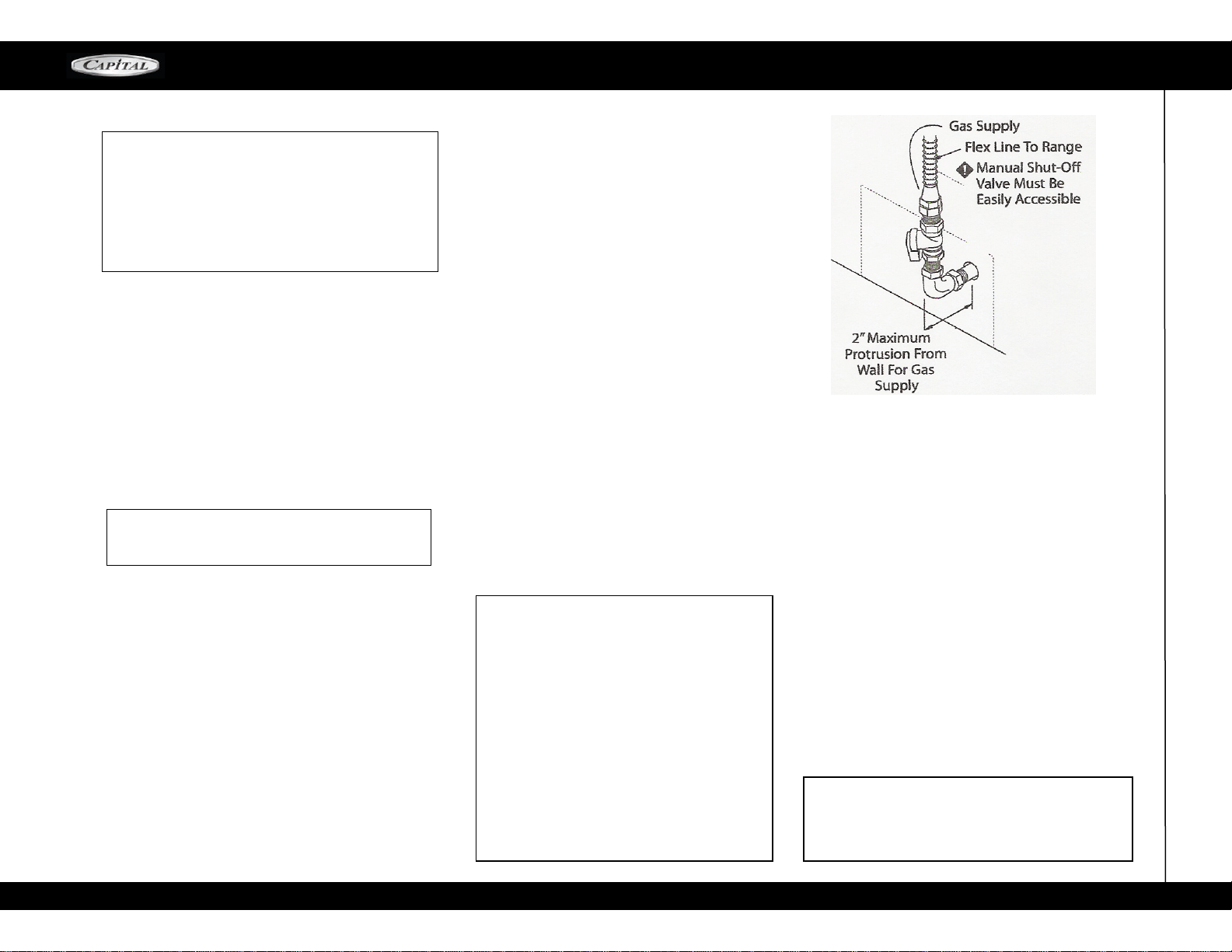
A manual shut off valve must be installed external
to
the range in an accessible location from the front
for
shutting off the gas supply when required.
The supply line MUST NOT protrude beyond the
back of the range.
Ensure that the gas supply is turned OFF at the
externalshut
-
offvalve before connecting the range.
The
gas
supply connection must be made by an
experienced technician and in accordance with
local codes or ordinances. In the absence of local
codes or ordinances, please refer to National Fuel
Gas Code ANSI Z223.1 / NFPA54
-
Current Issue.
The range is
supplied
with its ownpressureregulator
Use 5/8" diameter flex line to connect between the
gas supply and the appliance manifold pipe, which
exists at the upper left rear of the appliance. The
appliance manifold pipe connection is 1/2". Use
caution to avoid crimping the 5/8" flex line.
NOTE: the flex line for the gas supply must be
metal and approved by an approved certifying
agency (AGA, CGA, CSA, UL or CUL). NEVER use
a hose made of rubber or other synthetic material
as the heat may cause the hose to melt and de-
velop leaks, thus causing fires, physical and prop-
erty damage.
Always use pipe dope or Teflon tape on the pipe
threads, and be careful not to apply excessive pres-
sure when tightening the fittings.
Leak testing of the appliance shall be in accor-
dance with the manufacturer's instructions.
Turn on gas and check supply line connections for
leaks using a soap solution.
Never use a flame of
any sort to test for leaks.
CAUTION! The appliance must be isolated from the
gas supply piping system by closing its individual
manual shut
-
off valve during any pressure testing
of the gas supply piping system at test pressures
equal to or less than 112 psig (3.5kPa.).
The Appliance and its individual shut off valve
must be disconnected from the gas supply piping
system during any pressure testing of the system
at test pressures in excess of 1/2 psig (3.5kPa.).
When checking the manifold gas pressure, the inlet
pressure to the regulator should be at least 6.0".
DO NOT attempt any adjustment of the pres-
sure regulator.
TESTING AND ADJUSTMENTS
Install any loose components, such as burner caps
and
grates, oven racks that may have been removed
earlier to
facilitate moving the appliance. Be certain
that burner
caps seats properly
into the alignment slots in the burner
bases. Before
testing operation of the appliance, verify that
the unit
and the gas supply have been carefully
checked
for leaks and that the unit has been connected
to the electrical power supply. Turn the manual gas shut
-
off valve to the open position. Check the
operation of
the sealed gas burners by pushing
and turning each
knob counterclockwise to "Hl".
The burner igniters will
click until the flame ignites.
Burner flames should be
BLUE and stable with
no yellow tips, excessive
noise, or lifting of the
flame from the burner. If any of
these conditions exist, check that the air shutter (grill
and griddle only) or burner ports are not blocked or
clogged.
Remove any blockages that exist. If the flame is
too
yellow, indicating insufficient air, adjust the shutter
counterclockwise to increase air inlet (grill and
grid-
dle only).
CAUTION! A qualified technician must make
burner adjustments at the time of installation.
Improper or lack of adjustments may cause harmful
by
-
products or void your warranty!
WARNING! Gas line cannot be run inside back
cover of range. Run gas line in channel in back
of range.
HOOK UP
The open top burner flames should be approximately
1" to 1
-
1/4" High.
NATURAL GAS REQUIREMENTS:
PROPANE (LP) GAS REQUIREMENTS:
Inlet Connection: 1/2" N.P.T.
Min. 5/8" Dia. Flex Line.
Supply Pressure: 6" to 14" W.C.
Inlet Connection: 1/2" N.P.T.
Min. 5/8" Dia, Flex Line.
Supply Pressure: 11" to 14" W.C.
A Regulator is required at the LP source to provide
a maximum of 14" W.C. pressure to the range
regulator.
thathasbeenpermanently
mounted
totherangebody.
GAS HOOK
-
UP / TESTING AND ADJUSTMENTS
Loading ...
Loading ...
Loading ...