All-in-one Active Deterrence
Camera
User’s Manual
V1.0.0
ZHEJIANG DAHUA VISION TECHNOLOGY CO., LTD
User’s Manual
I
Foreword
Model
CDMS8113 Series
Safety Instructions
The following categorized signal words with defined meaning might appear in the manual.
Signal Words Description
Indicates a high potential hazard which, if not avoided, will
result in death or serious injury.
Indicates a medium or low potential hazard which, if not
avoided, could result in slight or moderate injury.
Indicates a potential risk which, if not avoided, may result
in property damage, data loss, lower performance, or
unpredictable result.
Indicates electrostatic Sensitive Devices.
Indicates the danger of high voltage.
Indicates a laser radiation hazard.
Indicates dangerous moving parts. Keep away from
rotating fan blades.
Indicates mechanical injuries caused by device parts.
Provides methods to help you solve a problem or save
your time.
Provides additional information as the emphasis and
supplement to the text.
Terms
To simplify descriptions, some frequently cited functions and names in this manual have the following
meanings:
Unless otherwise specified, “device” in this document refers to “All-in-one Active Deterrence
Camera”.
To keep the devices safe, IP addresses, MAC addresses, and serial numbers cited in this manual
have all been modified.

User’s Manual
II
Revision History
Version Revision Content Release Time
V1.0.0 First release. 2021.09

User’s Manual
III
Important Safeguards and Warnings
This section introduces the proper way of using the device, and danger and property damage
preventions. Before using the device, read this manual carefully. Follow the instructions and keep this
manual properly for future reference.
Operating Requirements
Do not place the Device in a place exposed to sunlight or near the heat source.
Keep the Device away from dampness, dust, or soot.
Keep the Device on a stable place to prevent it from falling.
Do not drop or splash liquid onto the Device, and make sure that there is no object filled with
liquid on the Device to prevent liquid from flowing into it.
Prevent foreign objects from entering the Device, which might result in damage.
Put the Device in a well-ventilated place, and do not block the ventilation of it.
Use the Device within the rated range of power input and output.
Do not dissemble the Device.
Transport, use, and store the Device under the allowed humidity and temperature conditions.
Do not expose the Device to water or excessive moisture when washing the car. A failure to follow
this instruction might result in short circuit, fire, or other malfunctions.
The dust on the circuit board will cause short circuit, which affect the normal operation of the
Device and even damage the Device. To make the Device work stably for a long time, please
regularly use the brush to remove the dust from components, including circuit board, connectors,
and chassis.
Keep the Device installed horizontally and make sure the internal anti-vibration components
work properly.
After all the cables are connected, tie up the cables to avoid the dangers such as short circuit, heat
and electric shock resulted from loose cables.
Pay attention to grounding of camera, since poor grounding might lead to chip damage.
Power Supply Requirements
Use the battery properly to avoid fire, explosion, and other dangers.
Replace the battery with that of the same type.
Use locally recommended power cord in the limit of rated specifications.
The appliance coupler is a disconnection device. Keep a convenient angle when using it.
Take care to complete the circuit connection. A failure to follow this instruction might result in
Device damage.
Prevent short circuit from occurring on all external wiring parts.
After all the lines connections are completed, you can start connecting power cable.
Ensure the project is well grounded to avoid interference to video and audio signals and avoid
electrostatic or induced voltage to damage the Device.
Unplug the power cable before you remove the audio/video signal cable, RS-232 or RS-485 cable;
otherwise these ports might be damaged.

User’s Manual
IV
Content
Foreword ............................................................................................................................................................ I
Important Safeguards and Warnings ............................................................................................................. III
1 Product Introduction .................................................................................................................................... 1
Overview ....................................................................................................................................................................................... 1
Function ......................................................................................................................................................................................... 1
2 Installation ..................................................................................................................................................... 3
Unpack and Check ..................................................................................................................................................................... 3
Device Structure ......................................................................................................................................................................... 3
2.2.1 Top Cover ......................................................................................................................................................................... 3
2.2.2 Side Panel Ports ............................................................................................................................................................. 4
2.2.3 Interface Definition ...................................................................................................................................................... 4
2.2.4 Dimensions ..................................................................................................................................................................... 7
Installation .................................................................................................................................................................................... 7
2.3.1 Installing SIM Card ........................................................................................................................................................ 8
2.3.2 Installing TF Card ........................................................................................................................................................... 8
2.3.3 Installing GPS Antenna ............................................................................................................................................... 8
2.3.4 Fixing Device ................................................................................................................................................................ 10
2.3.5 Connecting Power Cable ......................................................................................................................................... 10
Alarm Input and Output Connection ............................................................................................................................... 13
2.4.1 Alarm Input/Output Port Introduction ............................................................................................................... 13
2.4.2 Alarm Input Port Description ................................................................................................................................. 13
3 Basic Configuration ..................................................................................................................................... 15
Starting Device .......................................................................................................................................................................... 15
Initializing Device ..................................................................................................................................................................... 15
Logining in to Device .............................................................................................................................................................. 17
Configuring IP Address .......................................................................................................................................................... 19
Configuring General Setting ................................................................................................................................................ 21
3.5.1 Basic ................................................................................................................................................................................. 21
3.5.2 Date&Time ..................................................................................................................................................................... 22
Configuring Record Mode .................................................................................................................................................... 24
Configuring Storage Plan ...................................................................................................................................................... 25
3.7.1 Record Schedule ......................................................................................................................................................... 25
3.7.2 Snapshot Schedule .................................................................................................................................................... 27
4 Function Operations ................................................................................................................................... 30
Live ................................................................................................................................................................................................ 30
4.1.1 Real-time Monitoring Channels ............................................................................................................................ 31
Video Playback .......................................................................................................................................................................... 32
4.2.2 Control Bar ..................................................................................................................................................................... 33
4.2.3 Playing Back Recorded Video Files ....................................................................................................................... 34
4.2.4 Clipping Recording File ............................................................................................................................................ 35
Alarm Info ................................................................................................................................................................................... 36
5 System Settings ........................................................................................................................................... 38

User’s Manual
V
Configuring Alarm Events ..................................................................................................................................................... 38
5.1.1 Video Detection ........................................................................................................................................................... 38
5.1.2 Alarm Input ................................................................................................................................................................... 42
5.1.3 Exception ....................................................................................................................................................................... 44
5.1.4 Alarm Output ............................................................................................................................................................... 46
Configuring AI Plan ................................................................................................................................................................. 47
5.2.1 ADAS ................................................................................................................................................................................ 47
5.2.2 DSM .................................................................................................................................................................................. 50
File Backup .................................................................................................................................................................................. 52
Configuring Camera Parameter .......................................................................................................................................... 54
5.4.1 Camera Properties ...................................................................................................................................................... 54
5.4.2 Encode Parameters .................................................................................................................................................... 55
Configuring Network Parameters ...................................................................................................................................... 59
5.5.1 Port ................................................................................................................................................................................... 59
5.5.2 Wireless Network ........................................................................................................................................................ 61
5.5.3 3G/4G .............................................................................................................................................................................. 64
5.5.4 Email ................................................................................................................................................................................ 66
5.5.5 Register ........................................................................................................................................................................... 68
5.5.6 P2P .................................................................................................................................................................................... 68
Managing Storage Device .................................................................................................................................................... 69
5.6.1 Basic ................................................................................................................................................................................. 70
5.6.2 Disk Manager ................................................................................................................................................................ 71
5.6.3 FTP .................................................................................................................................................................................... 71
Configuring System ................................................................................................................................................................. 73
5.7.1 Configuring Serial Port Parameters ...................................................................................................................... 73
5.7.2 Managing Security ..................................................................................................................................................... 74
5.7.3 Configuring Vehicle Info ........................................................................................................................................... 75
Managing User Account ........................................................................................................................................................ 78
5.8.1 Managing User ............................................................................................................................................................. 79
5.8.2 Managing Group ......................................................................................................................................................... 81
5.8.3 Resetting Password .................................................................................................................................................... 82
6 Update .......................................................................................................................................................... 85
System Version .......................................................................................................................................................................... 85
Update.......................................................................................................................................................................................... 85
7 System Maintenance ................................................................................................................................... 87
Requirement for Maintenance ............................................................................................................................................ 87
System Information ................................................................................................................................................................. 87
7.2.1 Log .................................................................................................................................................................................... 87
7.2.2 Network Info ................................................................................................................................................................. 88
7.2.3 Disk ................................................................................................................................................................................... 88
7.2.4 Channel Info ................................................................................................................................................................. 89
7.2.5 Satellite Info .................................................................................................................................................................. 89
Automatic Maintenance ........................................................................................................................................................ 90
7.3.1 Auto Reboot .................................................................................................................................................................. 90
7.3.2 Auto Boot up ................................................................................................................................................................ 91
7.3.3 Auto Shutdown System ............................................................................................................................................ 91

User’s Manual
VI
7.3.4 Acc Delay ........................................................................................................................................................................ 91
Backup and Restore ................................................................................................................................................................. 92
7.4.1 Backing up Configurations ...................................................................................................................................... 92
7.4.2 Importing Configurations ........................................................................................................................................ 92
7.4.3 Restoring to Default ................................................................................................................................................... 93
Network Sniffer ......................................................................................................................................................................... 95
8 Logging in to the Device from DSS ............................................................................................................. 96
FAQ .............................................................................................................................................. 97
Storage Capacity Calculation .................................................................................................. 100
Legal Information .................................................................................................................... 101
Cybersecurity Recommendations ........................................................................................... 103

User’s Manual
1
1 Product Introduction
Overview
Developed on the new-generation platform, the all-in-one active deterrence camera is mobile video
monitoring products that integrate video capturing, locating, drive recording and intelligent analysis
functions.
It has the following features:
Up to 3 HDCVI video input channels and 1 built-in DSM video input channel.
The use of H.264/H.265 encoding ensures high encoding efficiency and saves storage space.
The needs of using the mobile products in different networks are taken into full consideration in
product design and 3G/4G modules or Wi-Fi modules are available.
The use of professional in-vehicle design in standard size features low power consumption and
novel shape.
Wide power voltage range adapts to various in-vehicle power supply.
Unique TF card storage design makes recording backup and management easier.
This product can be widely used for in-vehicle monitoring in public transportation, long-range
passenger transport, police patrol, urban management patrol, cash carriers, hazardous goods
transport, and logistics transport, or video monitoring in harsh environment.
Function
Table 1-1 Function Description
Function Description
Storage
Stores the data in the dedicated format which cannot be falsified to ensure the
data security.
Dual Stream
To cope with the low-bandwidth and instability of wireless network, the device
adopts the dual-stream technology (encode real-time video and the video in
network transmission separately) to optimize the encoding of network
transmission, which improves the control capability of wireless network
transmission.
Video Playback
Every channel takes recording in real time and independently, and you can
play backward, monitor through network, search and download recordings.
Supports several playback modes: Slow playback, fast playback, backward
playback, and frame-by-frame playback.
Displays the accurate time when the event occurred during playback.
Backup
Plug in a USB storage device (such as USB flash drive and mobile HDD) to back
up the data.
You can back up the data by downloading the files from the memory disk of
the device (such as TF card and USB flash drive) through the network.

User’s Manual
2
Function Description
Alarm Linkage
Provides 4-channel electric level alarm inputs that can connect to signals such
as car door signal, cornering lamp signal, reversing and braking signal, to give
an indication and take a record.
Supports one route of electric level alarm output to realize easy alarm linkage.
Protective circuit for alarm input and output ports to prevent device from
damage.
Rollover and
collision detection
Provides rollover and collision detection and timely releases alarms through the
platform.
Operation through
network
Supports remote operations through network, such as real-time remote
monitoring, video recording search and playback, and PTZ remote control.
3G/4G, Wi-Fi
Adopts the latest wireless communication technology, which has improved the
manageability of the device.
Communication
interface
Offers RS-485 port to connect with external devices.
Offers RS-232 port to connect with external in-vehicle display.
Offers standard Ethernet ports that support remote network access.
Compression
Supports multi-channel audio and video signals, and each channel signal
supports real-time compression by independent hardware to realize the sync
between sound and image.
Satellite positioning
Positioning history and recording linkage are available. Recording search can be
linked with vehicle moving track.
User’s Manual
3
2 Installation
This chapter introduces how to install the hardware of the device. Before installation, you need to
know the device information, such as top cover, side, dimensions, and ports. After obtaining a
sufficient understanding, you can install the SIM card, TF card, antenna and the device itself as needed.
Unpack and Check
When you receive the device, unpack the box for checks.
Firstly, check if there is any damage on the device appearance (although the packing materials are
specially selected for protecting the device from most of accidental hit during transportation).
Secondly, open the accessory box to check if the accessories are complete against the packing list.
Instructions about labels:
The labels on the device are very important for our after-sales service. To ensure the after-sales service,
keep the labels well, and do not tear or throw away. You need to provide the serial number of the
product when calling the after-sales service.
Device Structure
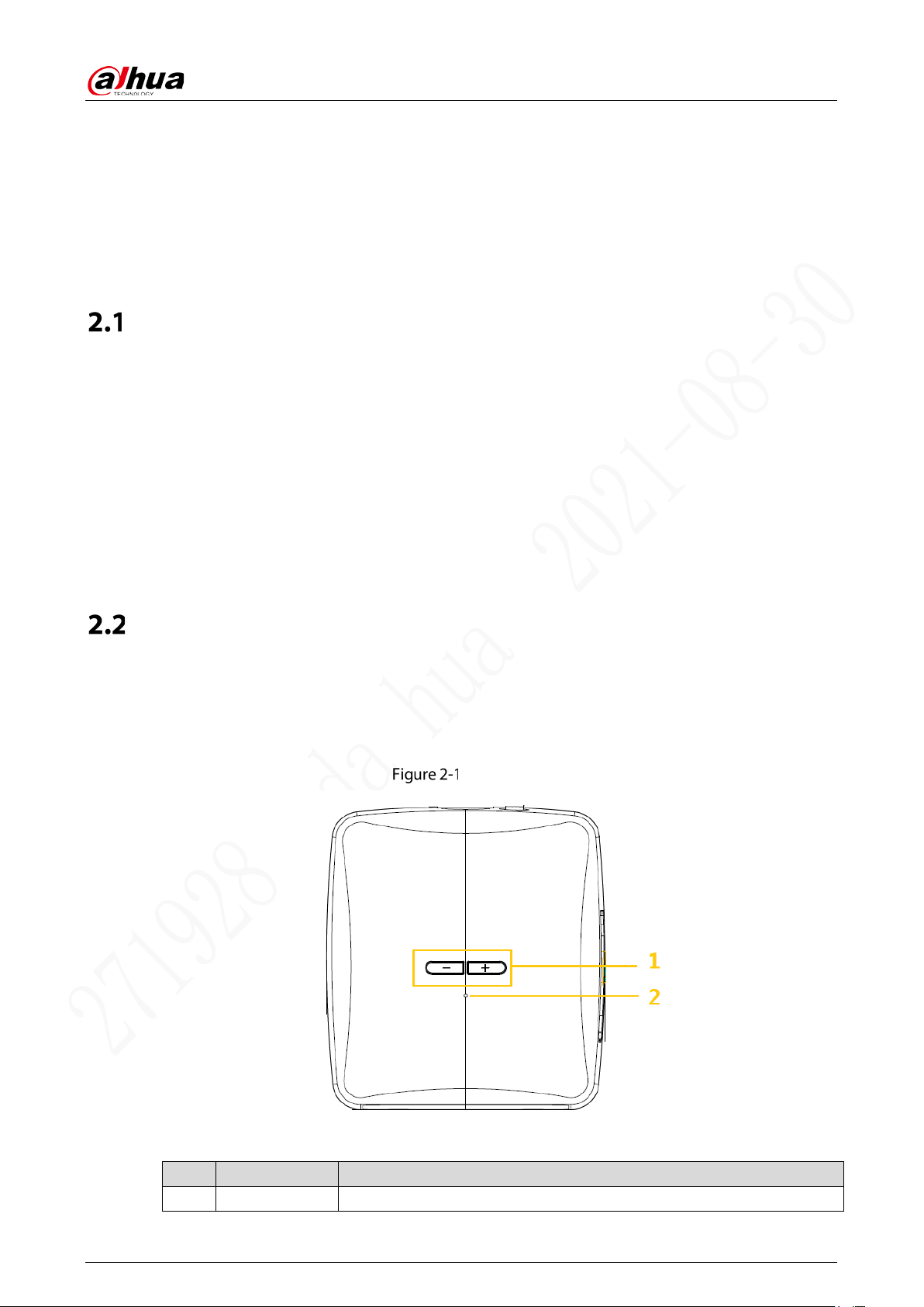
2.2.1 Top Cover
Describes the functions of the front indicators and ports.
Top cover
Table 2-1 Descriptions of ports and indicators
No. Name Descriptions
1 Volume Button Press “+” to turn up the volume and “-” to turn down the volume.
User’s Manual
4
No. Name Descriptions
2 Indicator Light
Blue light: Recording status indicator
Flashing: Recording is normal.
Solid blue: The camera is not recording.
Red Light: Connection status of GPS/4G
Flashing: The connection of GPS or 4G is abnormal.
Solid red: The connection of GPS and 4G is all abnormal.
Light off: The connection of GPS and 4G is all normal.
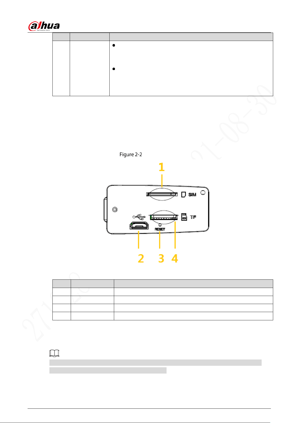
2.2.2 Side Panel Ports
Describes the ports functions of the side panel.
For the ports of the side panel, see Figure 2-2, Table 2-2 for ports function description, and “2.2.3
Interface Definition” for ports definitions.
Side panel ports
Table 2-2 Side panel port description
No. Name Function
1 SIM card port Insert SIM card.
2 USB port Connect the USB through a adapter cable.
3 RESET button Button for device reset.
4 TF card port Insert TF card.
2.2.3 Interface Definition
This manual only describes functions of each ports. You can follow these descriptions to prepare
cables or contact our sales staff for purchasing cables.

User’s Manual
5
2.2.3.1 Video Input
Video input
Table 2-3 Description
Name Description
1 VCC
2 Signal ground
3 Power ground
4
Signal
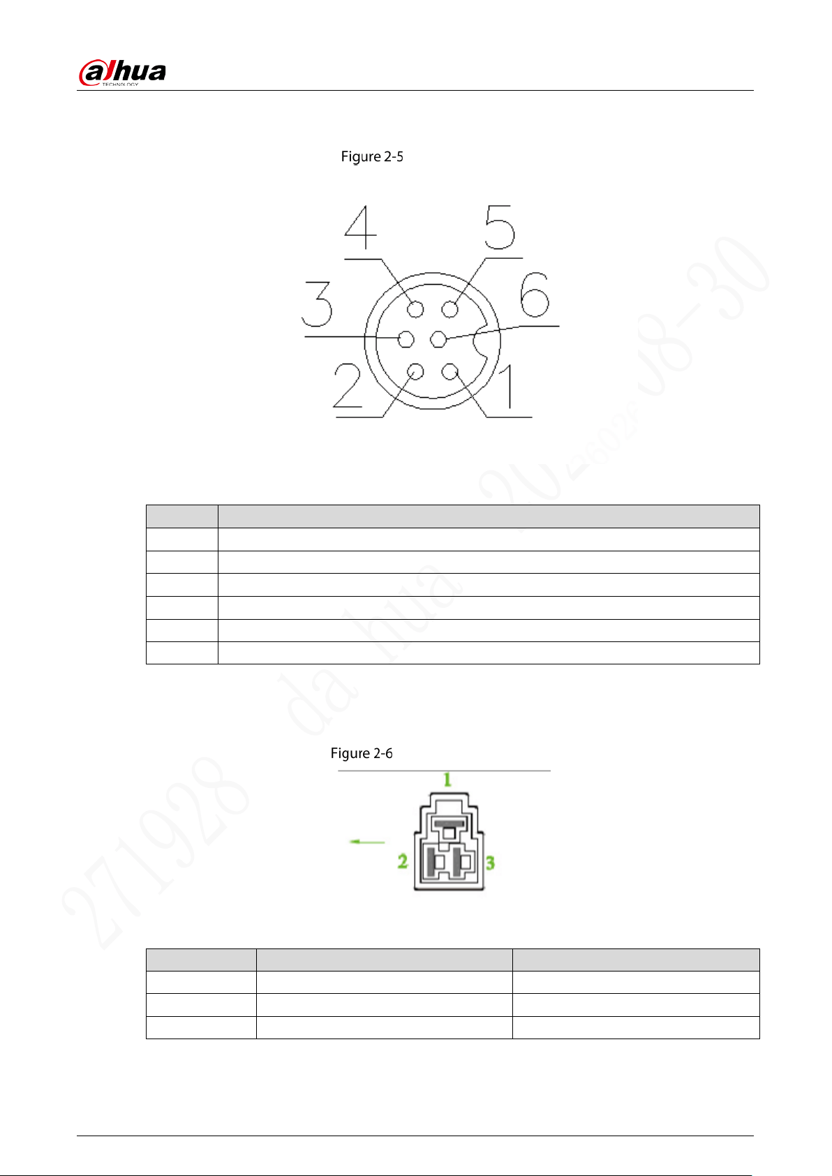
2.2.3.2 Alarm Screen Ports
Alarm screen ports
Table 2-4 Description
Name Description
1 12V
2 GND
3 RS232_RX
4
RS232_TX
5 GND
6 NC
7 NC
User’s Manual
6
2.2.3.3 Network Port
Network port
Table 2-5 Description
Name Function
1 Ethernet_TX-
2 Ethernet_TX+
3 12V
4
Ethernet_RX-
5 Ethernet_RX+
6 GND
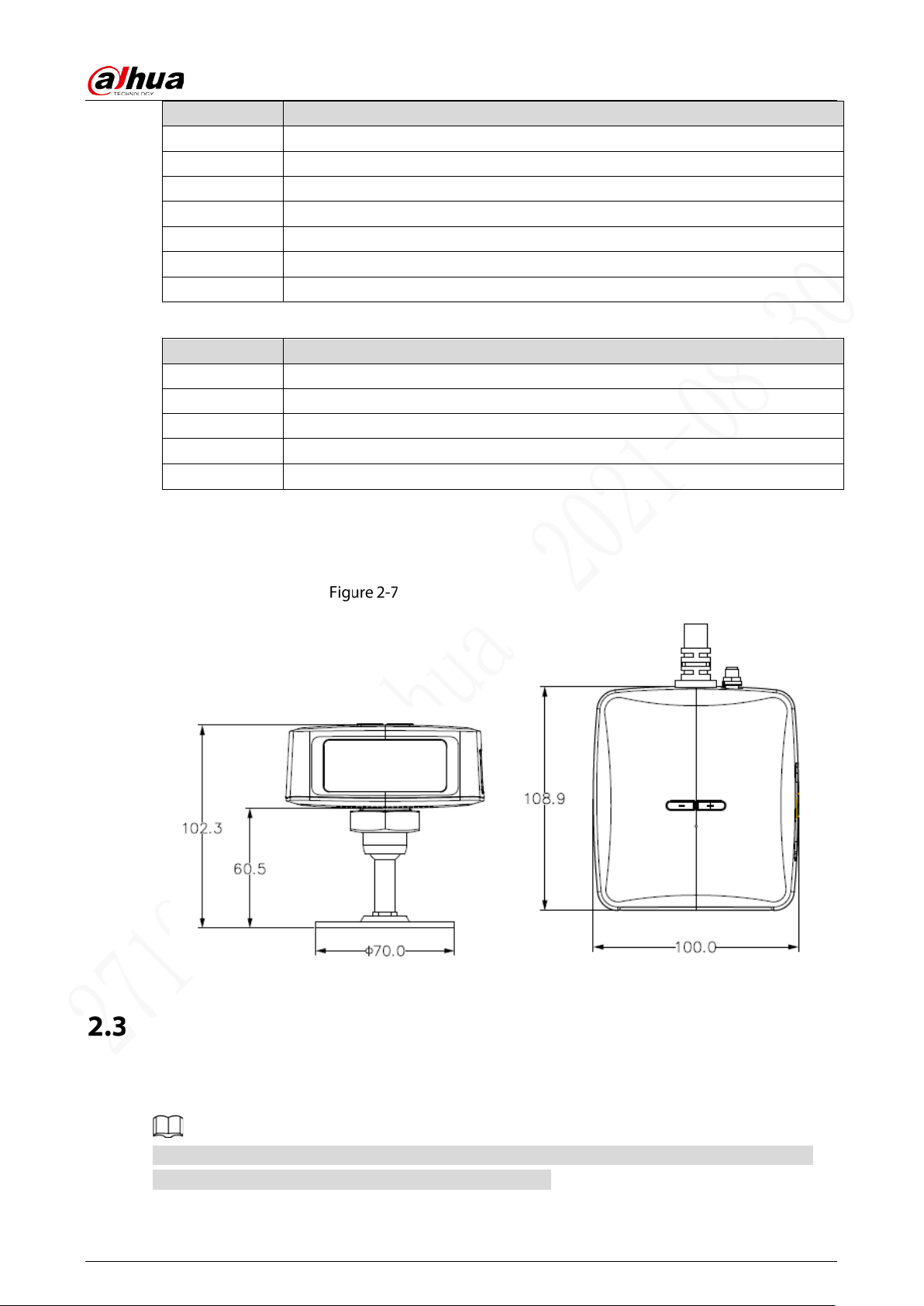
2.2.3.4 Power Input
Power input port
Table 2-6 Power input port description
Name Pins Cable Color
1 Ground Black
2 ACC signal input Orange
3 Anode input Red
Table 2-7 Cable Description (1)
User’s Manual
7
Color Pins
Yellow RS485+
Orange RS485-
Blue CAN_H
Green CAN_L
Brown RS232_TX
White RS232_RX
Purple RS232_GND
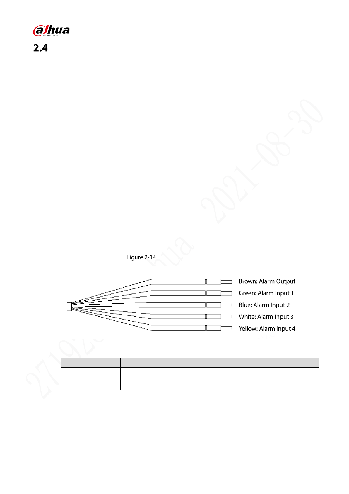
Table 2-8 Cable Description (2)
Color Pins
Brown Alarm output
Green Alarm input 1
Blue Alarm input 2
White Alarm input 3
Yellow Alarm input 4
2.2.4 Dimensions
Dimension (Unit: mm [inch])
Installation
When you receive the Device, unpack the box to check the device appearance and structures, and then
install SIM card and other items according to your network situation and storage requirement.
Before the installation is complete, make sure the device is disconnected from power, and do not
plug or unplug components when the power is connected.
User’s Manual
8
2.3.1 Installing SIM Card
The SIM card is not provided with the device by default. To connect the device to network through
dial-up connection, you need to purchase and install a SIM card.
Only supports the standard SIM cards.
Disassemble the SIM card cover.
Insert the SIM card into the card slot with corresponding marks.
Push the SIM card slot back to the device.
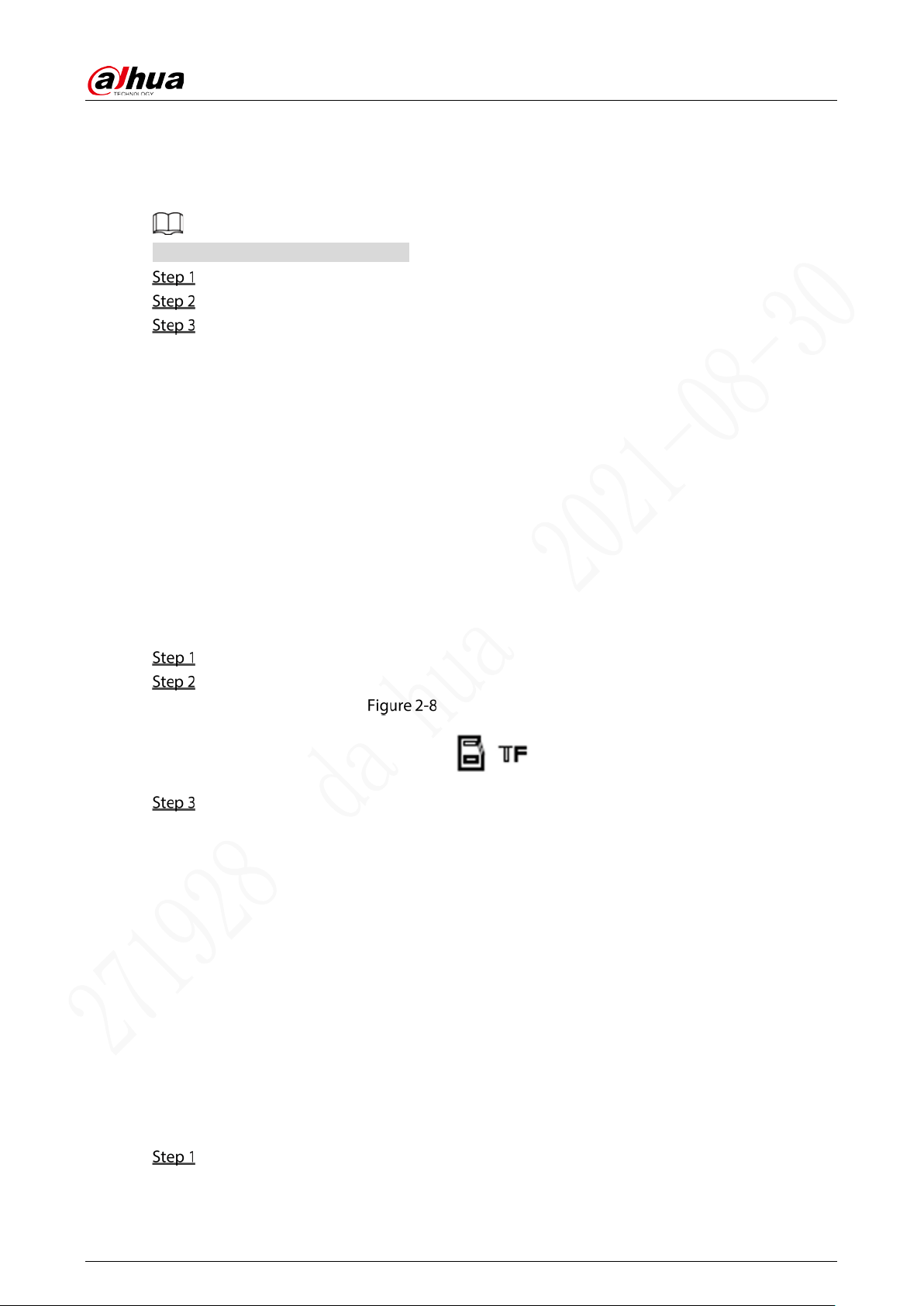
2.3.2 Installing TF Card
The TF card is not provided with the device by default. Please purchase and install it if needed.
Precondition
Make sure the device is disconnected from power source.
Procedure
The TF card slot is inside the device, do the following to install the TF card.
Disassemble the TF card cover.
Insert the TF card into the card slot with corresponding marks. See Figure 2-8.
Installing TF card
Reassemble the TF card and card slot. Fix the card cover with screws.
2.3.3 Installing GPS Antenna
The device antenna is installed to connect the device to the network and to locate the position of the
vehicle.
Positioning methods include the currently mainstream GPS positioning, Beidou positioning, with
corresponding GPS antenna and Beidou antenna.
In this document, GPS antenna is used as an example to illustrate the installation steps of locating
antennas. The installation process of other locating antenna is identical.
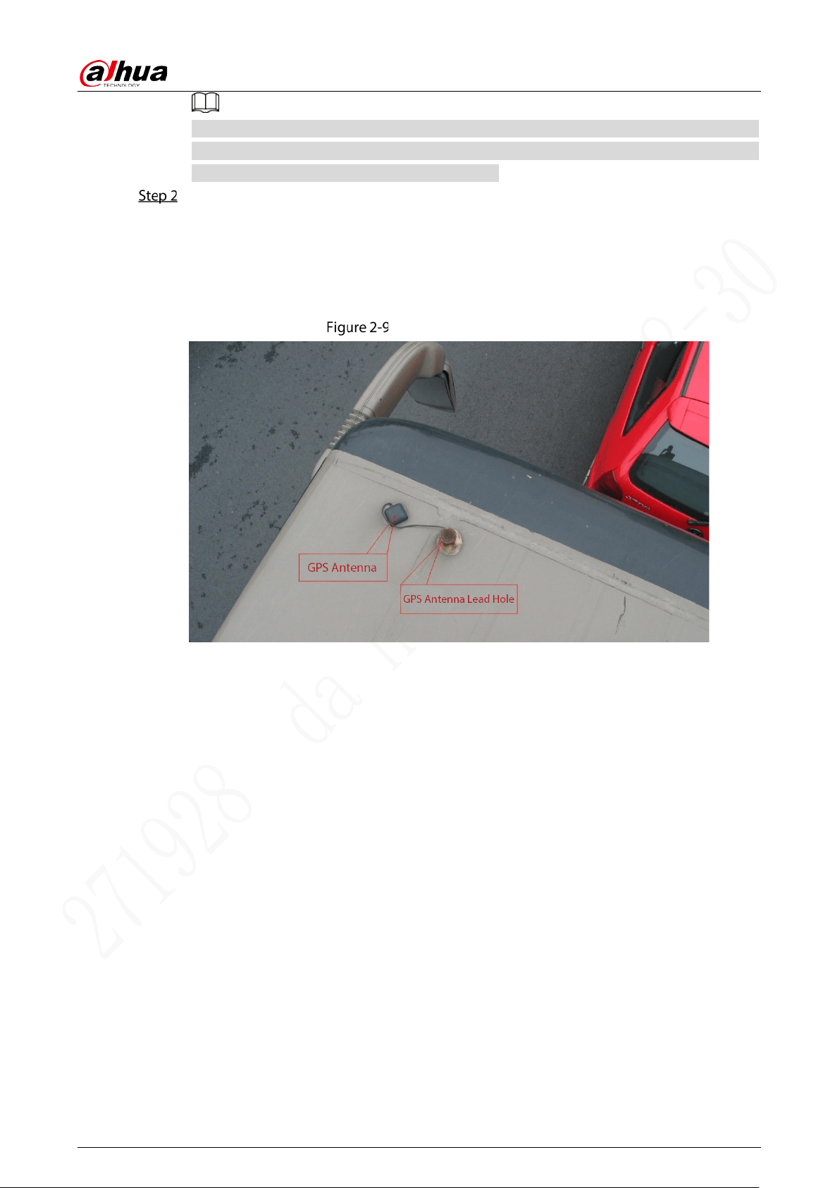
2.3.3.1 Outside Installation
Place the GPS antenna on the left front of the roof. See Figure 2-9.
The antenna is magnetically attached to the roof of the vehicle. Glue can be applied to four
sides of the GPS antenna to fix more reliably.
User’s Manual
9
To make the sensitivity and accuracy of positioning free of interference, ensure that there is
no high-power electrical or electronic interference source (such as a fan or AC compressor) or
obstacles within 1 meter around the GPS antenna.
Insert the GPS antenna lead wire into the antenna lead hole on the roof of the vehicle and
connect to the GPS antenna port inside the vehicle.
The requirements of the GPS antenna lead hole are as follows.
The inner radius is at least Ø10mm.
It must be waterproof.
Easy to replace and maintain the antenna.
Outside installation
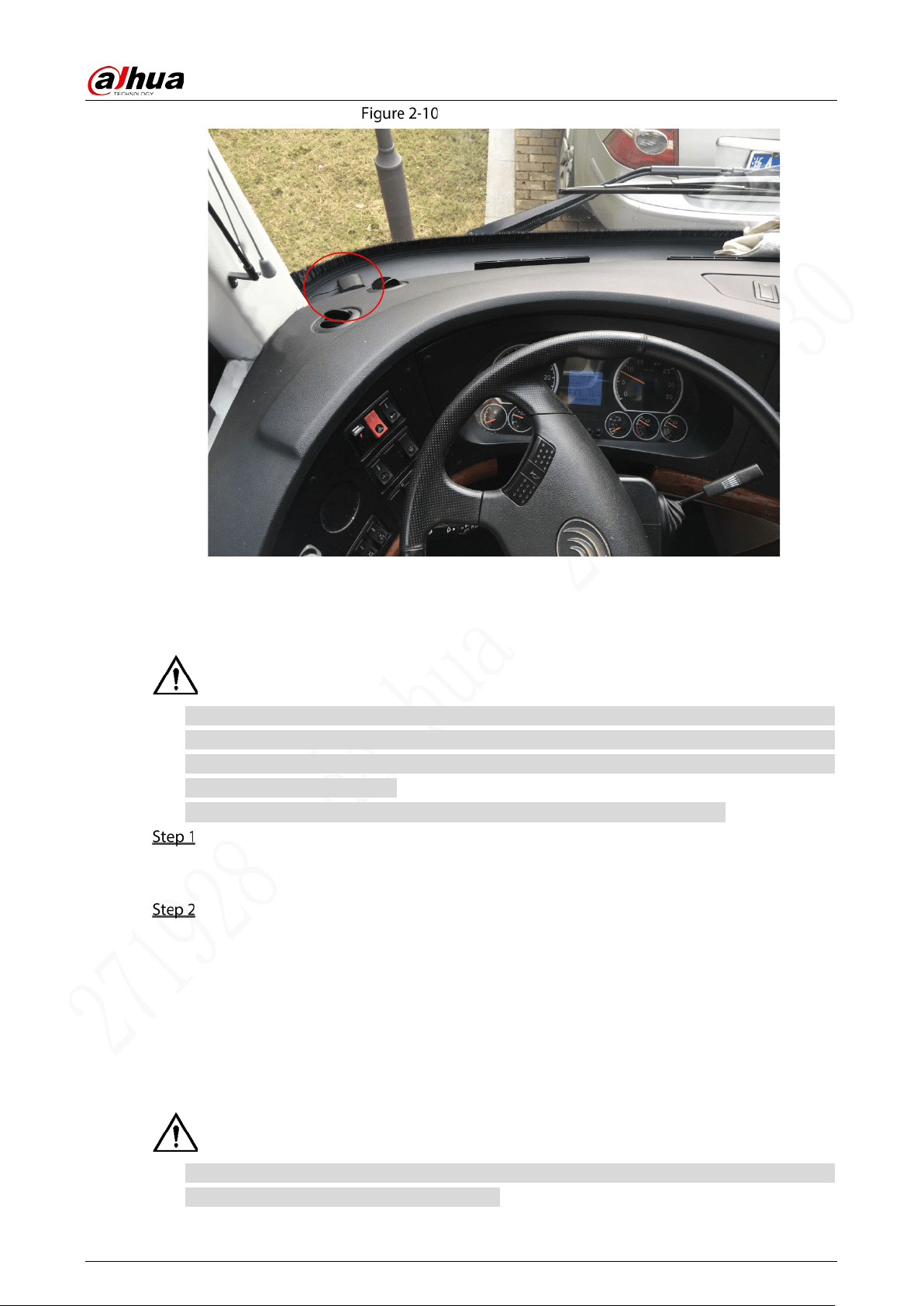
2.3.3.2 Inside Installation
When limited by waterproof and wiring requirements, the antenna can be installed inside the vehicle.
To select the installation place, it is recommended to place the antenna horizontally on the dashboard
close to the windshield, and make the GPS cable facing upward to enhance the signal, as shown in
Figure 2-10.
User’s Manual
10
Inside installation
2.3.4 Fixing Device
Install the device on the vehicle where it cannot be seen from outside. Avoid places with high
temperature or near the air conditioning system. High temperature shortens the life of the device.
If the device is too close to the air conditioner, the condensing water from the air conditioner can
short circuit or burn the device.
Power on the camera only after all external devices are connected correctly to it.
Fix the camera onto the vehicle.
1) Punch holes on the vehicle according to the installation dimensional drawing.
2) Use screws to fix the device onto the vehicle.
Connect cables to the device.
Check the voltage of the accumulator. The working voltage of this device ranges from 7V
to 36V. To make sure the device works stably, directly get power supply from the
accumulator.
When installing the basic wires, do not use excessive force to pull the control wires.
2.3.5 Connecting Power Cable
Before connecting the power cable, confirm whether the input voltage is between 7V–36V DC. If
it is out of the range, it will damage the device.
User’s Manual
11
Please make sure that the positive and negative poles of the power are connected correctly. If not,
the device may be damaged.
The diameter of the power cable should be more than 1.0mm
2
. Use power cables recommended
by our company.
When connecting the cables to the device, make sure that the main power switch of the vehicle
is turned off and the key of the vehicle is placed in the off state.
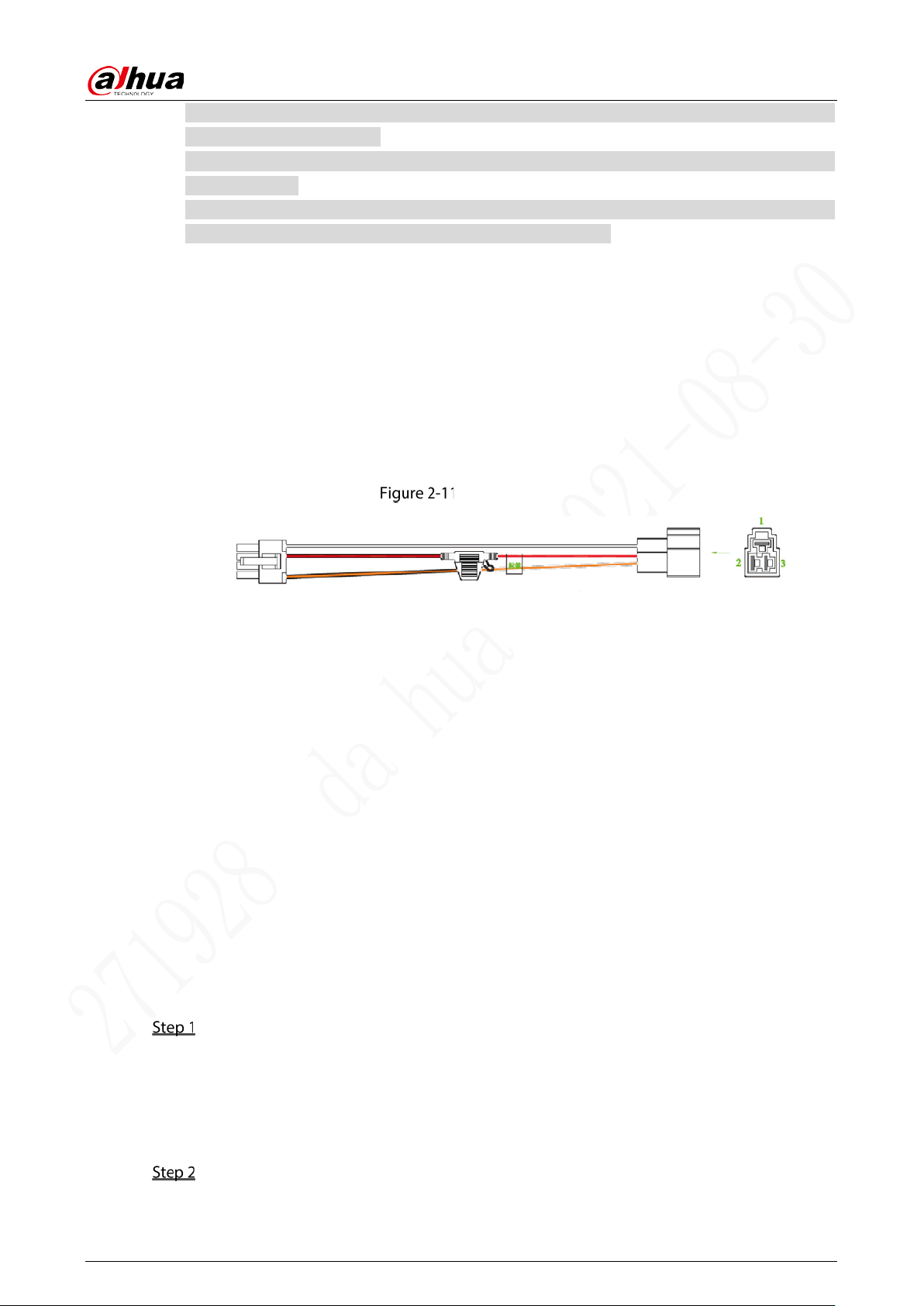
2.3.5.1 Overview
For the power cable of the device, see Figure 2-11.
Connect one end of the power cable to the power port of the device (the left port in the figure),
connect the other end to the vehicle battery (the right port in the figure).
The red one with fuse is positive pole of the power (always-live wire).
The black one is the grounding cable.
The orange one is the ACC signal (key starting wire).
Power cable
2.3.5.2 Obtain Connection Modes
In order to ensure correct cable connection, it is necessary to obtain the connection mode of the main
power switch through three methods.
Ask the vehicle manufacture the connection modes of the main power switch of the vehicle.
Measure with a multimeter: disconnect the main switch, then measure the voltage between the
vehicle body and the positive pole of the vehicle battery. If the voltage is 12V or 24V, it means that
the main switch disconnects the positive pole. If the voltage is 0V, then the main switch
disconnects the negative pole.
Visual inspection: whether the switch cable near the vehicle battery is connected to the positive
pole or the negative pole.
2.3.5.3 Connecting Operation
The camera must be connected to the ground wire, ACC signal, and constant electricity.
Enable the main power switch on the vehicle, place the key in the OFF state, and then measure
the normal live electricity of the vehicle.
Use a multimeter to measure the voltage on the fuse by switching to the DC voltage range.
When the multimeter detects voltage, it measures the normal live electricity on the vehicle.
Generally, the voltage is 24V DC for large vehicles and 12V DC for small vehicles. However, this
is subject to actual data.
When the vehicle key is placed at the ACC state or the ON state, the ACC signal of the vehicle
is measured.
User’s Manual
12
Use a multimeter to measure the voltage on the fuse by switching to the DC voltage range.
When the multimeter detects voltage, remove the car key. If the voltage changes to 0V, it
means that the measured signal is ACC on the car.
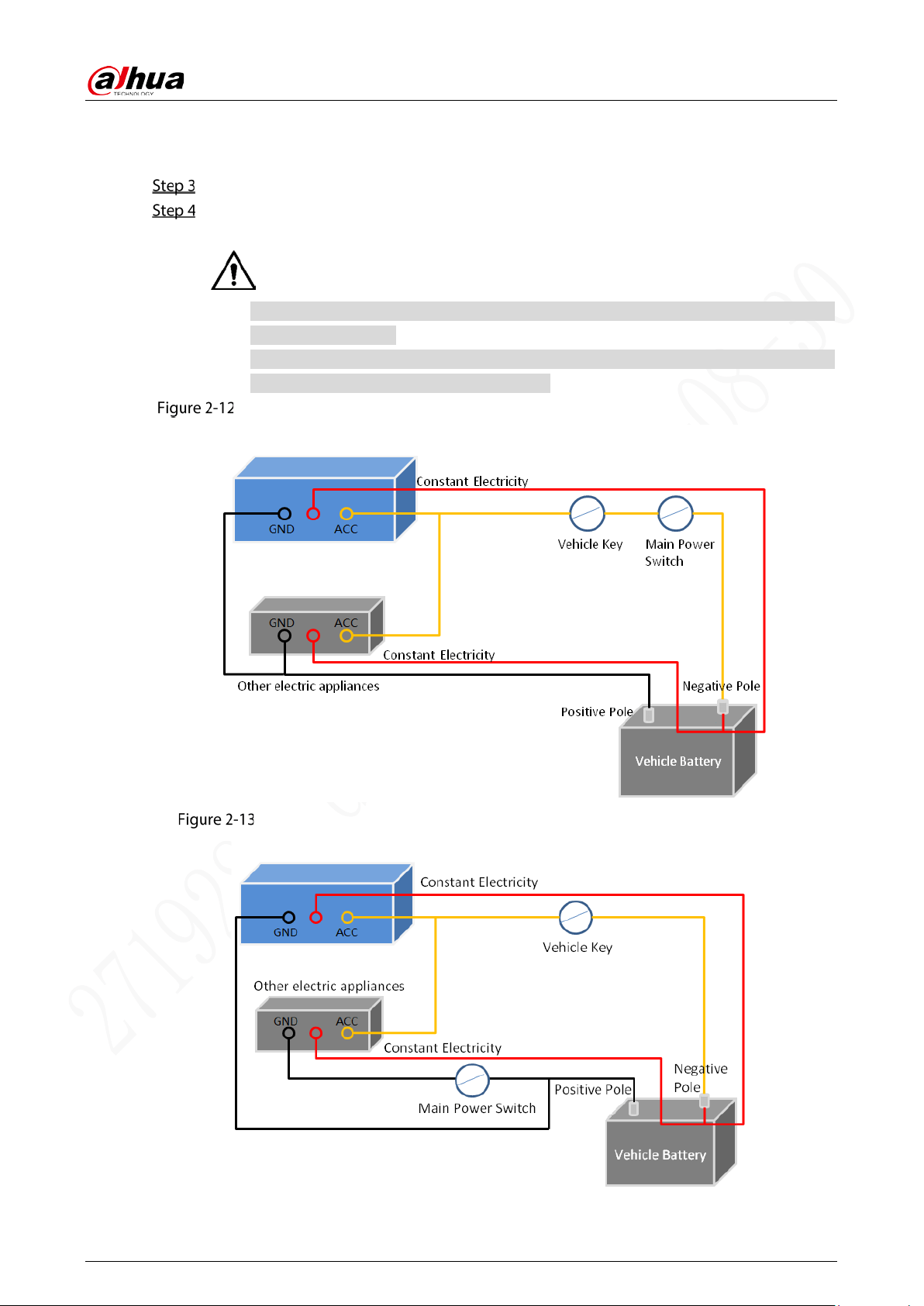
Turn off the main power switch on the vehicle, and place key in the OFF state.
Connect the power cable according to the main power switch installation mode. See Figure
2-12 and Figure 2-13.
The positive and negative poles of the battery must be equipped with protective
devices such as fuses.
For vehicles where the master power switch is installed at the cathode of the
accumulator, isolation installation is needed.
Vehicle main power switch installed on the positive pole of the vehicle battery
Vehicle main switch installed on the negative pole of the vehicle battery
User’s Manual
13
Alarm Input and Output Connection
Before using the alarm function, learn about the connections method of alarm input and output port.
Alarm Input
The alarm input port supports alarm signal from ground and device of 12V-24V voltage.
If the alarm device is connected to the device and other devices, use relay for isolation.
Alarm Output
The alarm output port cannot be connected to high-power load (less than 1A). When constructing the
output circuit, the excessive current should be prevented from causing damage to the relay. Use the
contactor for isolation when applying high-power loads.
No Restriction for Types of Alarm Input
The alarm input can be Normal Open or Normal Closed.
2.4.1 Alarm Input/Output Port Introduction
Describes alarm input and output ports.
Alarm Input/output Ports
Table 2-9 Alarm input ports description
Name Description
Alarm Output Port Alarm output port that outputs alarm signal to alarm device.
Alarm Input Port Alarm In 1–4, local alarm input port.
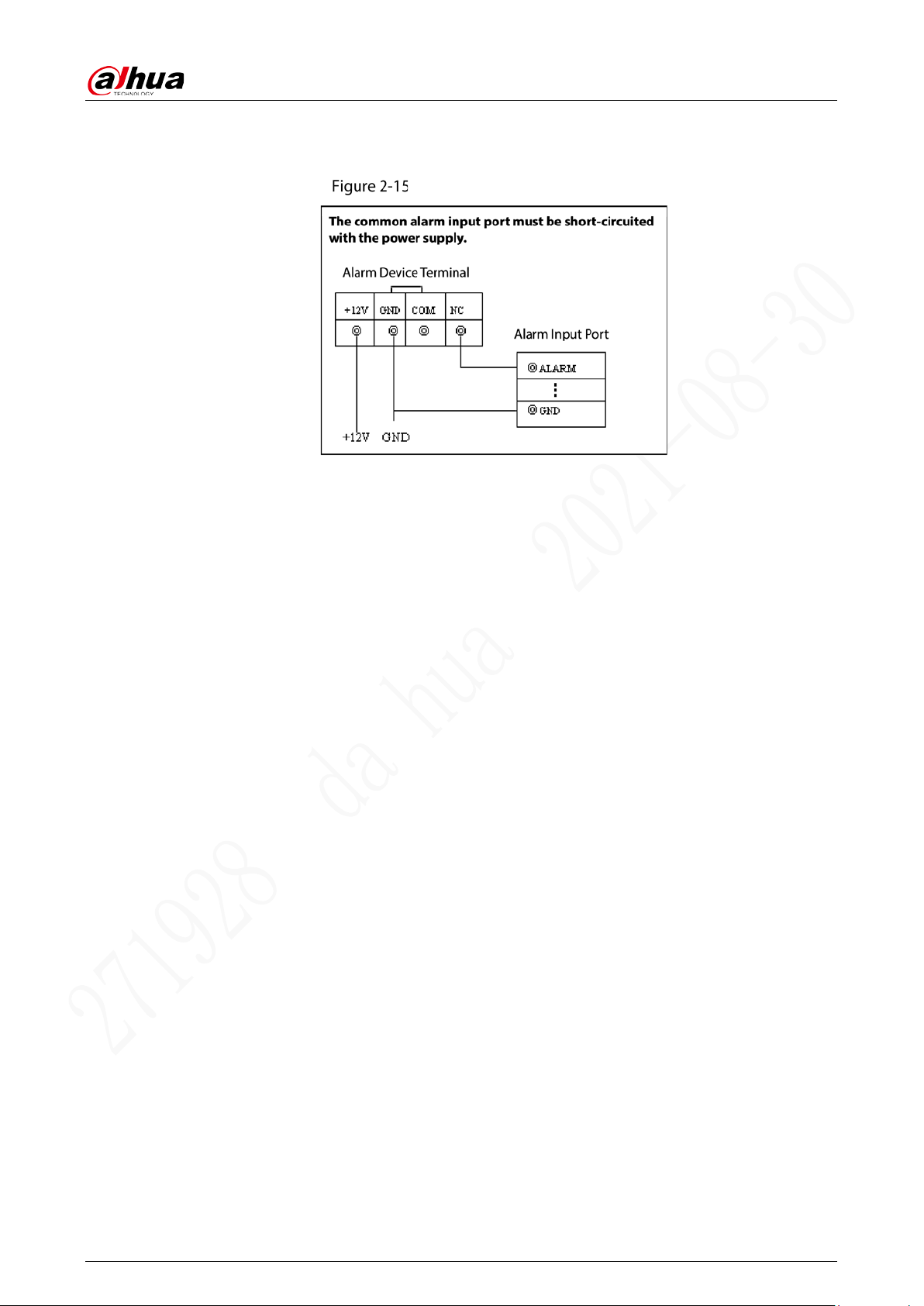
2.4.2 Alarm Input Port Description
Both NO and NC are supported.
The GND of alarm detector is in parallel connection with COM (the power supply of alarm detector
should be from external power source). See Figure 2-15.
The GND of alarm detector is in parallel connection with GND of device.
User’s Manual
14
Connect the NC port of alarm detector to the alarm input port (ALARM).
When supplying power from external power source to the alarm device, the alarm device should
be common-grounded with the device.
NC alarm input illustration

User’s Manual
15
3 Basic Configuration
This device can be operated following instructions on the APP or WEB interface. This section introduces
the WEB interface instructions. The local interface is similar and would not be elaborated here.
There are several browsers are supported, including Safari, Firefox, and IE.
Click Refresh, the system displays the latest saved configuration.
Starting Device
Before turning on the device, check whether the input voltage is correct against the device power
requirement.
To ensure the stable work of the device and the external devices connected to the device and to
prolong the service life, we recommend that you should refer to the national related standard to
use the power source that provides stable voltage with less interference from ripples.
In the first power-on, the device needs connection to the ACC to work as intended.
For the first boot up or after restoring to the default factory settings, the initialization interface is
displayed on the screen. Follow on-screen instructions to initialize your device prior to use.
Initializing Device
When you are opening the device for the first time or you have allowed your system to be restored the
factory settings, you need to initialize the device. Only after that can you operate and configure your
device.
Prerequisites
Please make sure the correct network connection between PC and the device.
Procedure
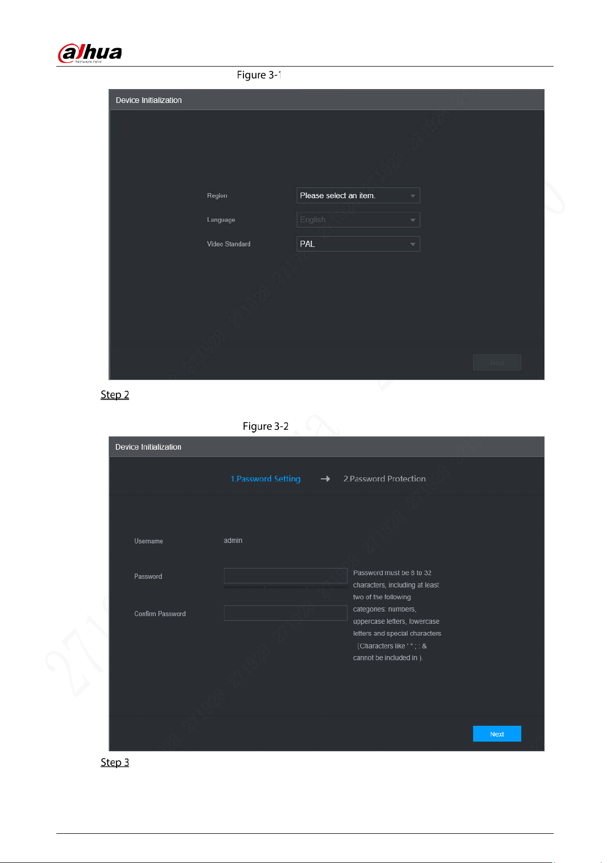
Open the browser, enter the Device IP address (the default IP address is 192.168.1.108), and
then press Enter.
The Device Initialization interface is displayed. See Figure 3-1.
User’s Manual
17
Password protection
Select the reset type based on your needs. It is recommended to enable the two types as
follows.
Select Reserved Email and then enter email address.
Check the Security Question box, select the question and enter the corresponding
answer.
Click OK.
Device initialization completed.
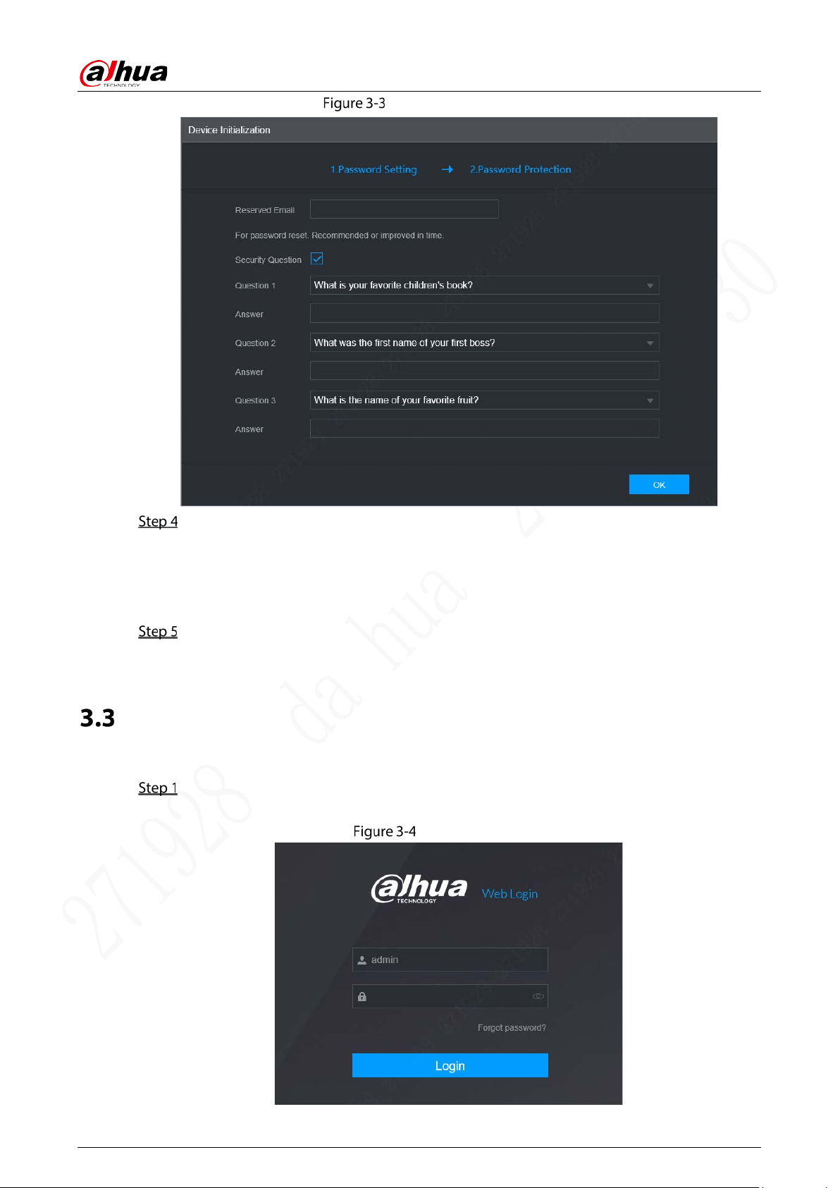
Logining in to Device
You can log in to and then configure the device.
Open the browser, enter the Device IP address, and then press Enter.
The WEB Login interface is displayed. See Figure 3-4.
WEB Login
User’s Manual
18
Enter user name and password, and then click Login.
For admin account, if you forget password, click Forgot password? to find back the password.
For details, see “5.8.3 Resetting Password”.
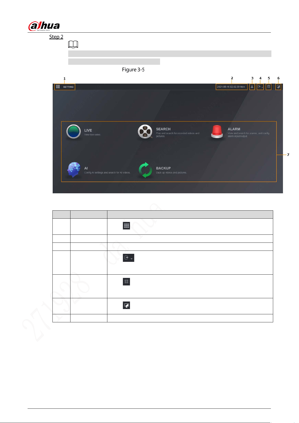
WEB interface
Table 3-1 Description of WEB interface
No. Name Description
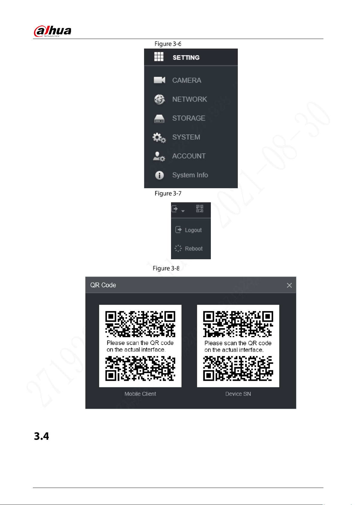
1 Setting
Click or Setting. See Figure 3-6.
2 Time Display the current time.
3 User Display the user that currently logs in.
4 Logout
Click , the system displays as Figure 3-7. Select Logout or Restart as
needed.
5 QR Code
Click , the system displays as Figure 3-8. Scan device serial number to
add the device to APP.
6 Desktop
Click to return to WEB main interface.
7 Operation System operation
User’s Manual
19
Setting
Logout
QR Code
Configuring IP Address
Connect the device to the network and make sure the device can communicate with other devices in
the network diagram.
User’s Manual
20
Prerequisites
Make sure the device is connected to the network properly.
Procedure
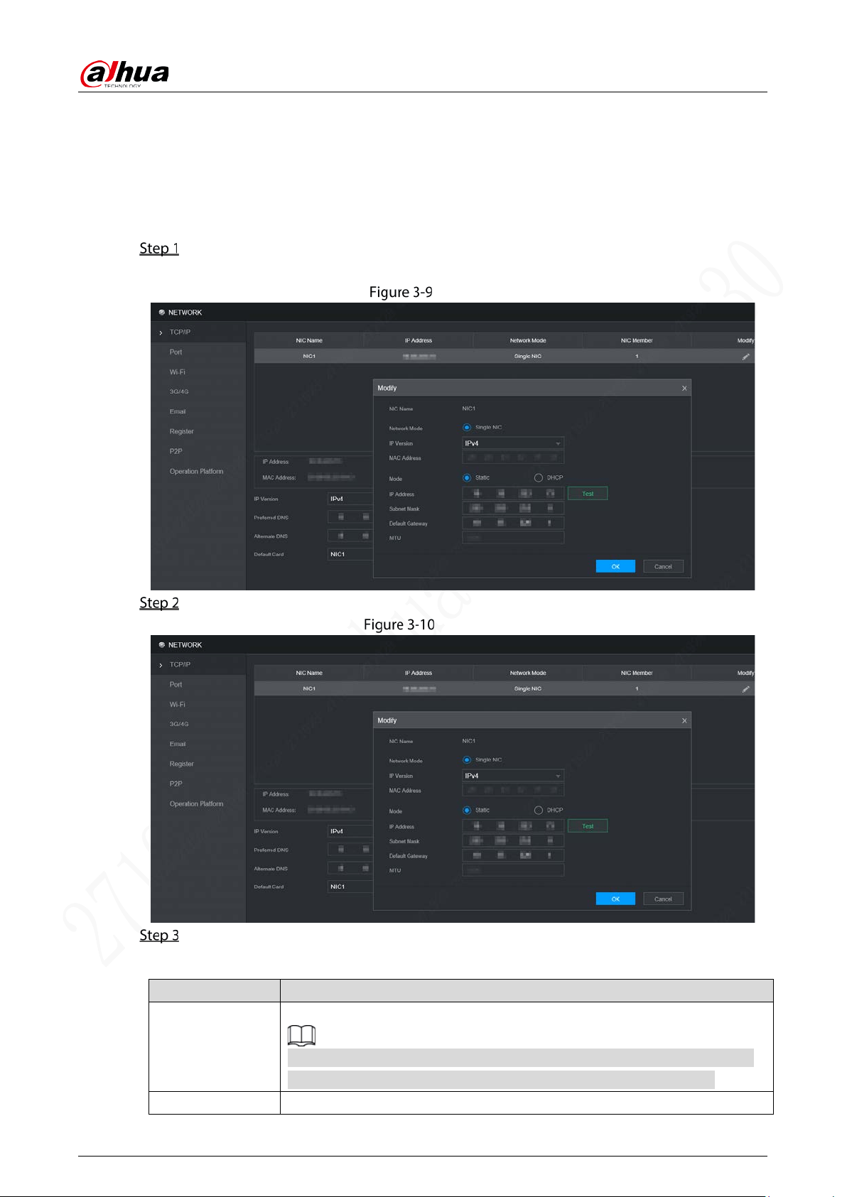
Select Setting > Network > TCP/IP.
The TCP/IP interface is displayed, see Figure 3-9.
TCP/IP
Click Modify. The Modify interface is displayed. See Figure 3-10.
Modify
Configure parameters. For details, see Table 3-2.
Table 3-2 TCP/IP parameters description
Parameter Description
IP Version
Select IPv4 or IPv6. Both versions are supported.
For IPv6 version, in the IP address box, Gateway box, Preferred DNS box,
and Alternate DNS box. Please enter 128 bits and it cannot be blank.
MAC Address MAC address of the host, which cannot be modified.
User’s Manual
21
Parameter Description
DHCP
The system automatically obtains an IP address. When the DHCP function is
enabled, the IP address, Gateway, and Subnet mask cannot be set
manually.
No matter the DHCP function is enabled or not, you can view the current IP
address.
IP Address According to your network plan, enter the modified IP address, gateway and
subnet mask.
Please ensure IP address and subnet mask are in the same network segment,
which means the front parts of the IP address and of the default gateway are
the same one.
Subnet Mask
Default Gateway
Preferred DNS IP address of DNS server.
Alternate DNS Alternate IP address of DNS.
Click OK.
Configuring General Setting
You can configure the basic settings, including basic and Date&Time.
3.5.1 Basic
Set up the general information of the device, including language, video standard, menu standby
duration, license plate, and more.
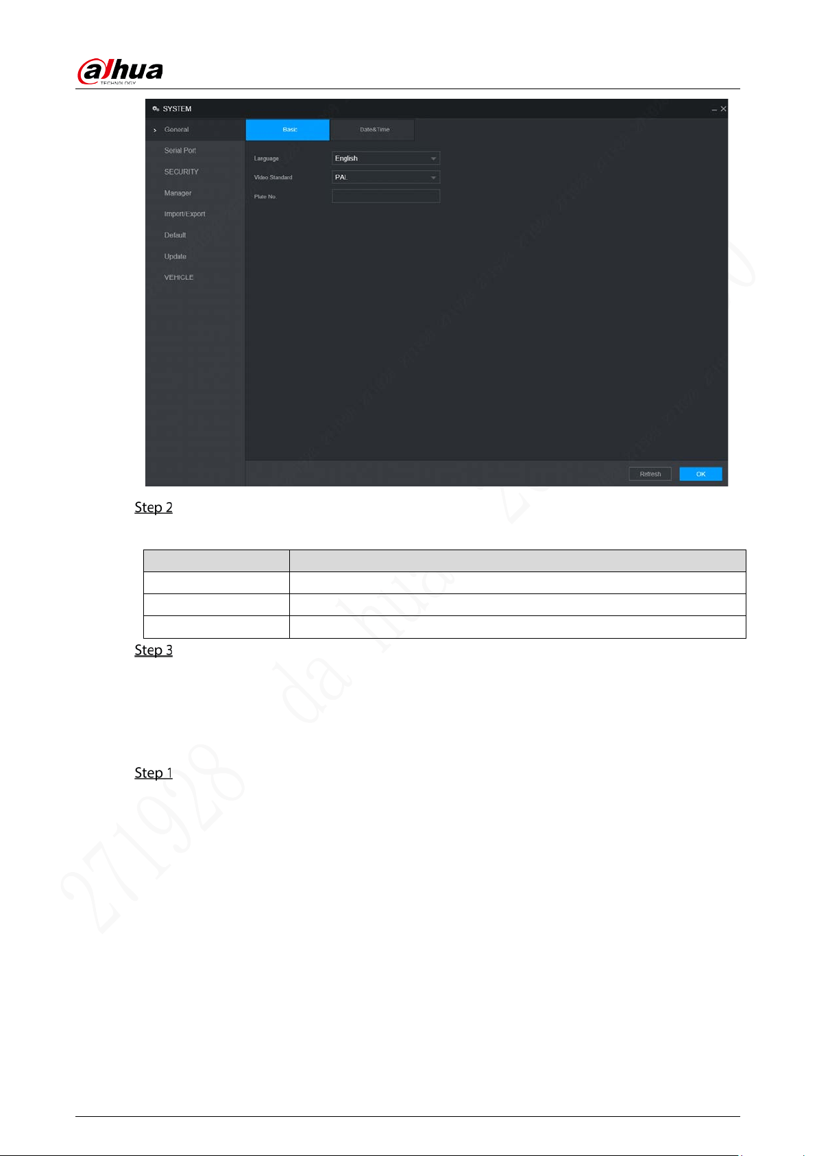
Select Setting > System > General > Basic.
The Basic interface is displayed. See Figure 3-3.
Table 3-3 Basic
User’s Manual
22
Configure parameters. For details, see Table 3-4.
Table 3-4 General settings parameters description
Parameter Description
Language Select a language for the system.
Video Standard Displays the video encode standard.
Plate No Enter the plate number of vehicle where the device is located.
Click OK.
3.5.2 Date&Time
You can configure settings such as date format, time format, and timing mode.
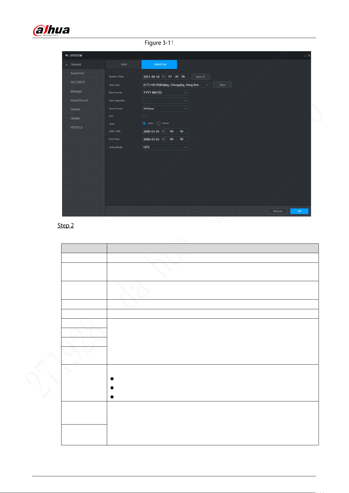
Select Setting>System > General > Date&Time.
The Date&Time interface is displayed. See Figure 3-11.
User’s Manual
23
Date&Time
Configure parameters. For details, see Table 3-5.
Table 3-5 Date&Time parameters description
Parameter Description
System Time Displays the current system date and time.
Time Zone
The time zone where the device locates.
In the Timing Mode list, if GPS or NTP is selected, configure this parameter.
Date Format
Set the date display format of the device, including YYYY-MM-DD, MM-DD-YYYY
and DD-MM-YYYY.
Date Separator Separator style of date.
Time Format Select a time format, including 24-hour and 12-hour.
DST The DST is applied in some countries or regions. Select the DST check box if it is
applied where the device is located
1. Select the DST check box.
2. According to the local regulations, configure the type, start time and end
time for the DST.
DST Type
Start Time
End Time
Timing Mode
Select a timing mode, including DSS, GPS, and NTP. The default selection is NTP.
DSS: The system time syncs with DSS platform.
GPS: The system time syncs with satellite.
NTP: The system time syncs with NTP server that you configured.
Server Address
In the Timing Mode list, if NTP is selected, configure this parameter.
After configuring NTP server, the device syncs time with NTP server.
Port
User’s Manual
24
Parameter Description
Interval
1. In the Timing Mode list, select NTP to enable the NTP timing function.
2. Configure parameters.
Server: Enter IP address of NTP server.
Synchronize: Click Manual Update to sync the device time with NTP
server.
Port: The system supports TCP protocol only and the default setting is
123.
Interval: Enter the interval that you want the device to sync time with
the NTP server. The maximum value is 65535 minutes.
Click OK.
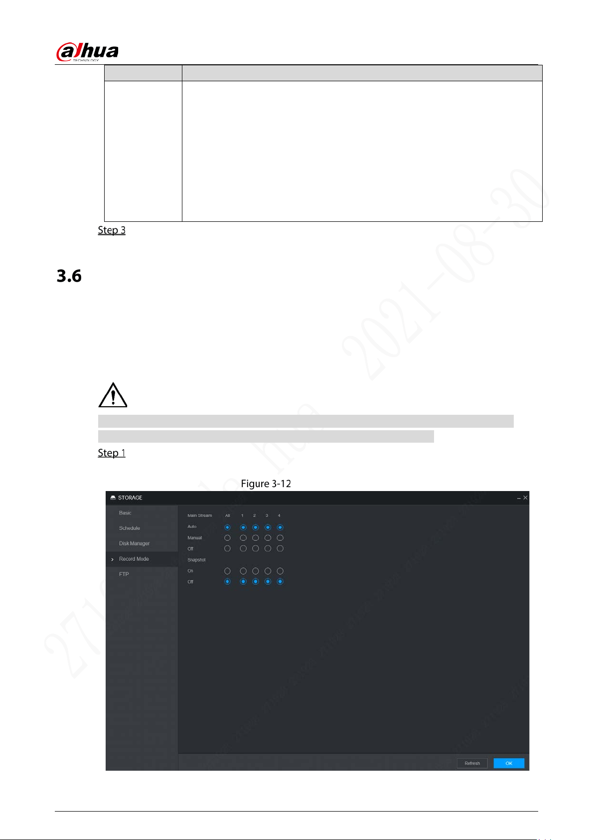
Configuring Record Mode
The record mode is consisted of manual mode and auto mode. You can also enable or disable the
snapshot function.
Auto: The recording starts automatically according to the record type and recording time as
configured in the recording schedule.
Manual: Keep general recording for 24 hours for the selected channel.
Manual recording operation requires the user have the permission to access Storage Settings.
Check to ensure the HDD installed in the device has been formatted properly.
Select Setting > Storage > Record Mode.
The Record Mode interface is displayed, see Figure 3-12.
Record mode
User’s Manual
25
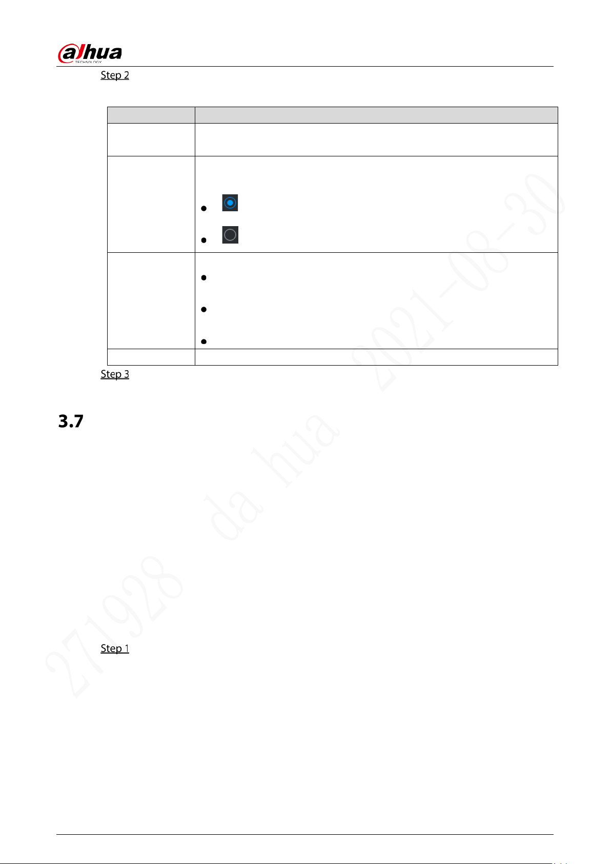
Configure parameters. For details, see Table 3-6.
Table 3-6 Record control parameters description
Parameter Description
Channel
Displays the channel number.
You can select one or several channels or select All.
Status
Indicates the recording status of corresponding channels. The choices include
Auto, Manual, Enable, and Close.
: Selected.
: Not selected.
Auto/Manual/Off
Select the recording mode, including Manual, Auto, and Stop
Manual: Top priority. When the Manual check box is selected, the system
keeps general recording for 24 hours for the corresponding channel.
Auto: The system starts recording according to the record type (such as
general alarm, motion detect, and system alarm) and recording time.
Stop: Do not record.
On/Off Enable or disable the scheduled snapshot for the corresponding channels.
Click OK.
Configuring Storage Plan
3.7.1 Record Schedule
The default recording setting is 24 hours recording for all channels. You can configure the record type
and recording time according to your actual situation.
Prerequisites
The auto recording is enabled for the corresponding channel. For details, see “3.6 Configuring Record ”.
Procedure
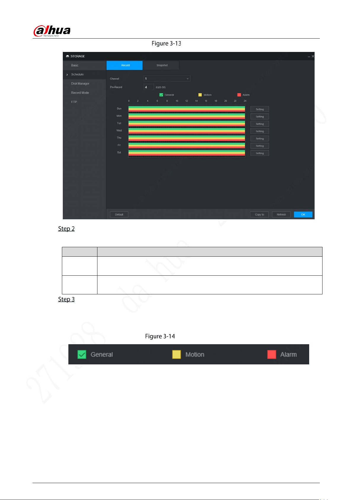
Select Setting > Storage > Schedule > Record.
Record interface is displayed. See Figure 3-13.
User’s Manual
26
Record
Configure parameters. For details, see Table 3-7.
Table 3-7 Record schedule parameters description
Parameter Description
Channel
Select a channel to configure the corresponding recording schedule. If you configure
the same setting for all channels, select All.
Pre-record
Start recording for 0 seconds to 30 seconds before the alarm event occurs. If you
enter 0 seconds, there will be no pre-recording.
Set periods of the record by drawing or editing.
Drafting method
1. Select the type of recordings by selecting the check box in front of the type. See
Figure 3-14.
Record type
2. Press and hold the left button and drag the mouse in the period illustration to draft
the period.
There are six periods in one day. The device activates recordings of the preset type
in each preset period. In the period illustration displayed in the figure, the color bar
shows the Recording Type corresponding to the period.
Green means general recordings are effective.
Yellow means motion recordings are effective.
Red means alarm recordings are effective.

User’s Manual
27
Draw
Editing Method
1. Click Setting corresponding to the week.
The Setting interface is displayed. See Figure 3-16.
Setting
2. Select the record type and weekday, and enter the recording period.
3. Click OK.
The recording schedule appears on the Recording Plan interface to view the
configured recording schedule directly.
Click OK.
Click Copy to and you can copy the settings to other channels.
Click Default, and the device is restored to default configuration.
3.7.2 Snapshot Schedule
You can configure the storage schedule for taking the snapshot.
User’s Manual
28
Prerequisites
The snapshot is enabled for the corresponding channel. For details, see “3.6 Configuring Record ”.
Procedure
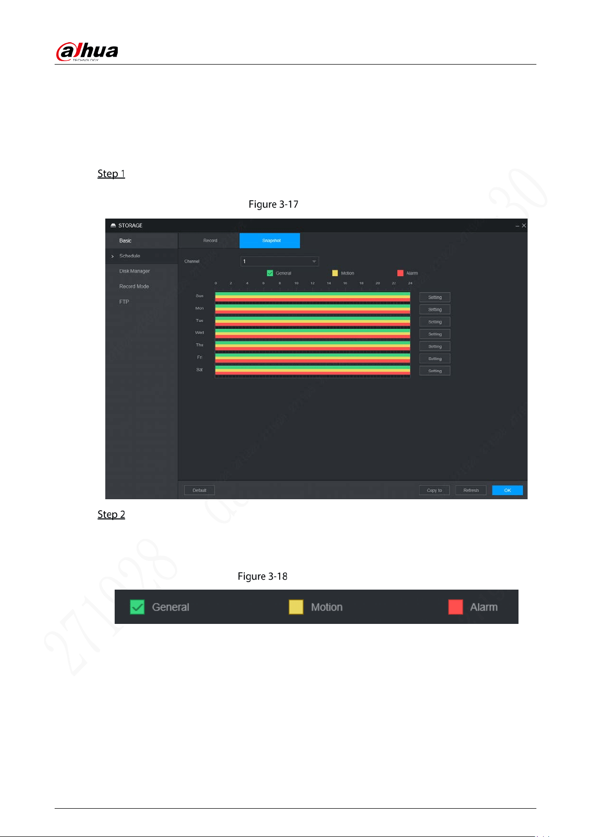
Select Setting > Storage > Schedule > Snapshot.
The Snapshot interface is displayed. See Figure 3-17.
Snapshot
Set snapshot period by drafting and editing.
Drafting method
1. Select the type of snapshot by selecting the check box in front of the type. See
Figure 3-18.
Snapshot Type
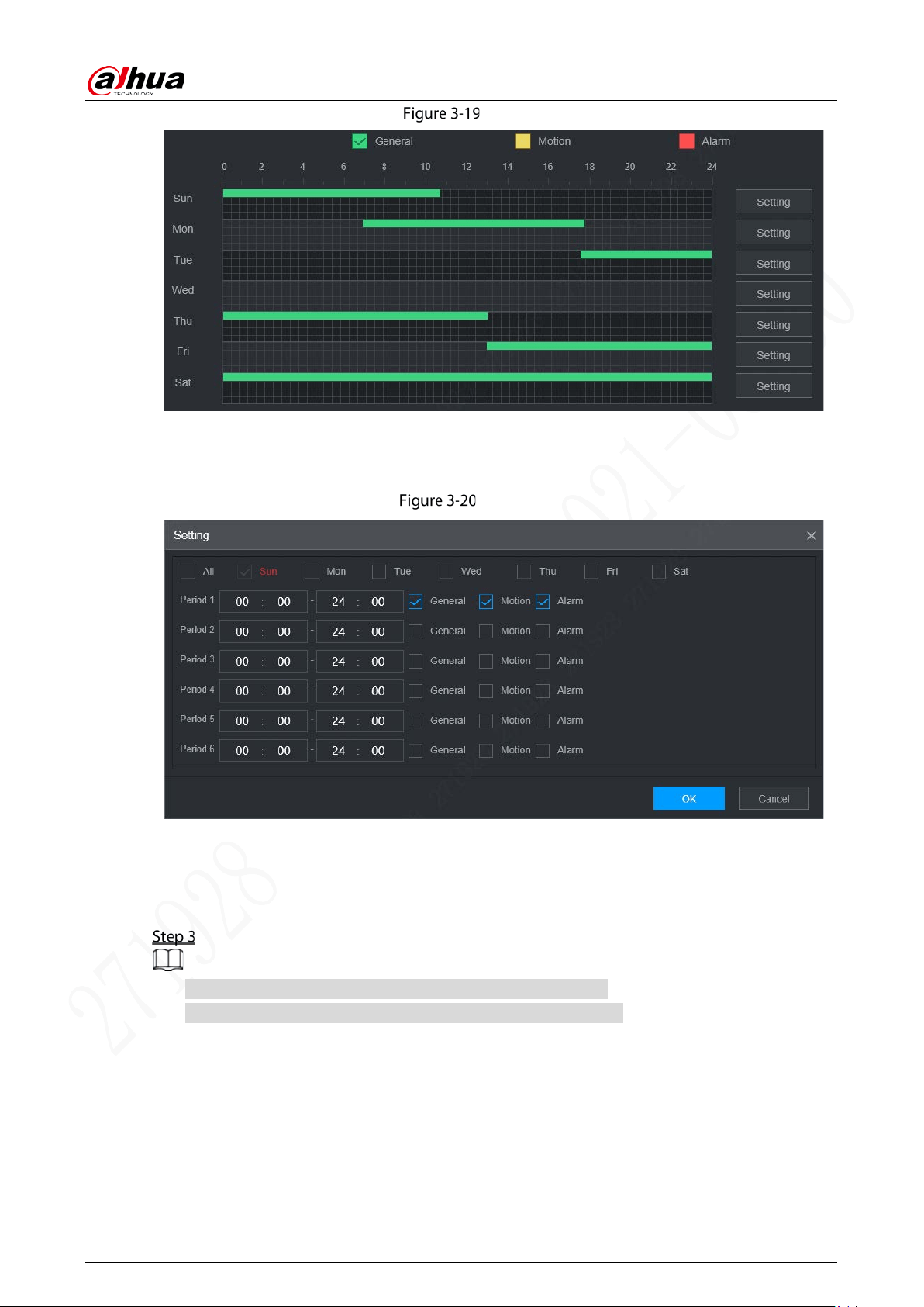
2. Press and hold the left button and drag the mouse in the period illustration to draft
the period.
You can set six periods in one day. The device activates the snapshot method of the
preset type in each preset period. In the period illustration displayed in the figure,
the color bar shows the Snapshot Type corresponding to the period.
Green means general snapshots are effective.
Yellow means motion detection snapshot are effective.
Red means alarm snapshots are effective.
User’s Manual
29
Draw
Editing Method
1. Click Setting.
The Setting interface is displayed. See Figure 3-20.
Period
2. Select the snapshot type and weekday, and enter the period for taking snapshot.
3. Click OK.
Snapshot schedule appears on the Snapshot interface to view the configured
snapshot schedule directly.
Click OK.
Click Copy to and you can copy the settings to other channels.
Click Default, and the device is restored to default configuration.
User’s Manual
30
4 Function Operations
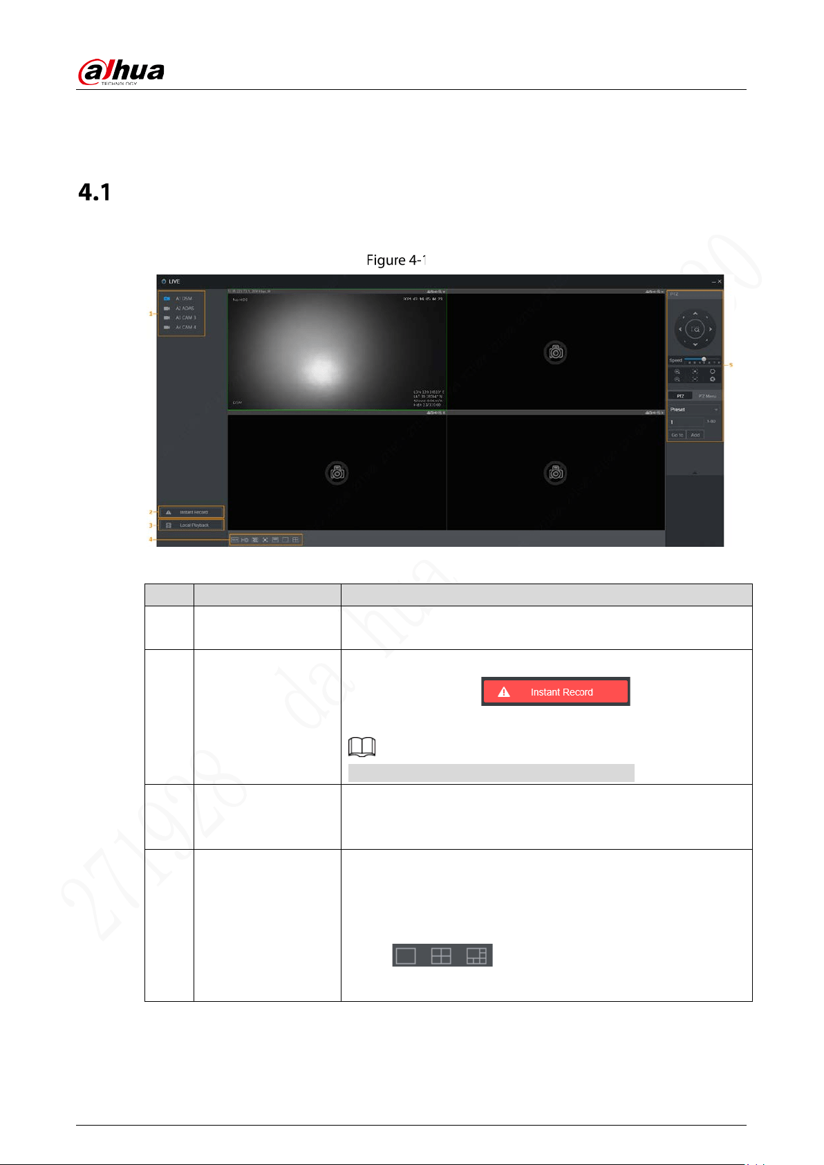
Live
Log in and click Live, the Live interface is displayed. See Figure 4-1.
Live
Table 4-1 Live interface parameters description
No. Name Description
1
Real-time Monitoring
Channels
See “4.1.1Real-time Monitoring Channels”.
2 Instant Record
Click Instant Record and the recording type switches to Manual,
and the icon turns to ; click Instant
Record again to switch the record type back to Auto.
This function is only supported by main stream.
3 Local Playback
Plays back the video file (.dav) stored on the PC.
Click Local Playback, select the video file in the pop-up dialog
box, and then click Open to start playing back the video file
4
Window Function
Operations
Configure the scale, image quality, playback fluency, full screen,
and window split mode.
For real-time monitoring, you can select the fluency or real-time
to be the priority according to your actual requirement.
Select to split the preview window as
necessary.
User’s Manual
31
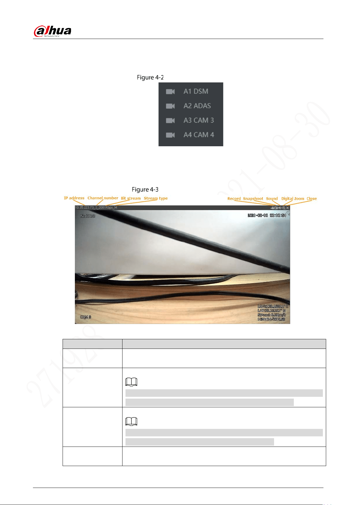
4.1.1 Real-time Monitoring Channels
Displays the list of monitoring channels.
Monitoring channels
Operations in monitoring channels
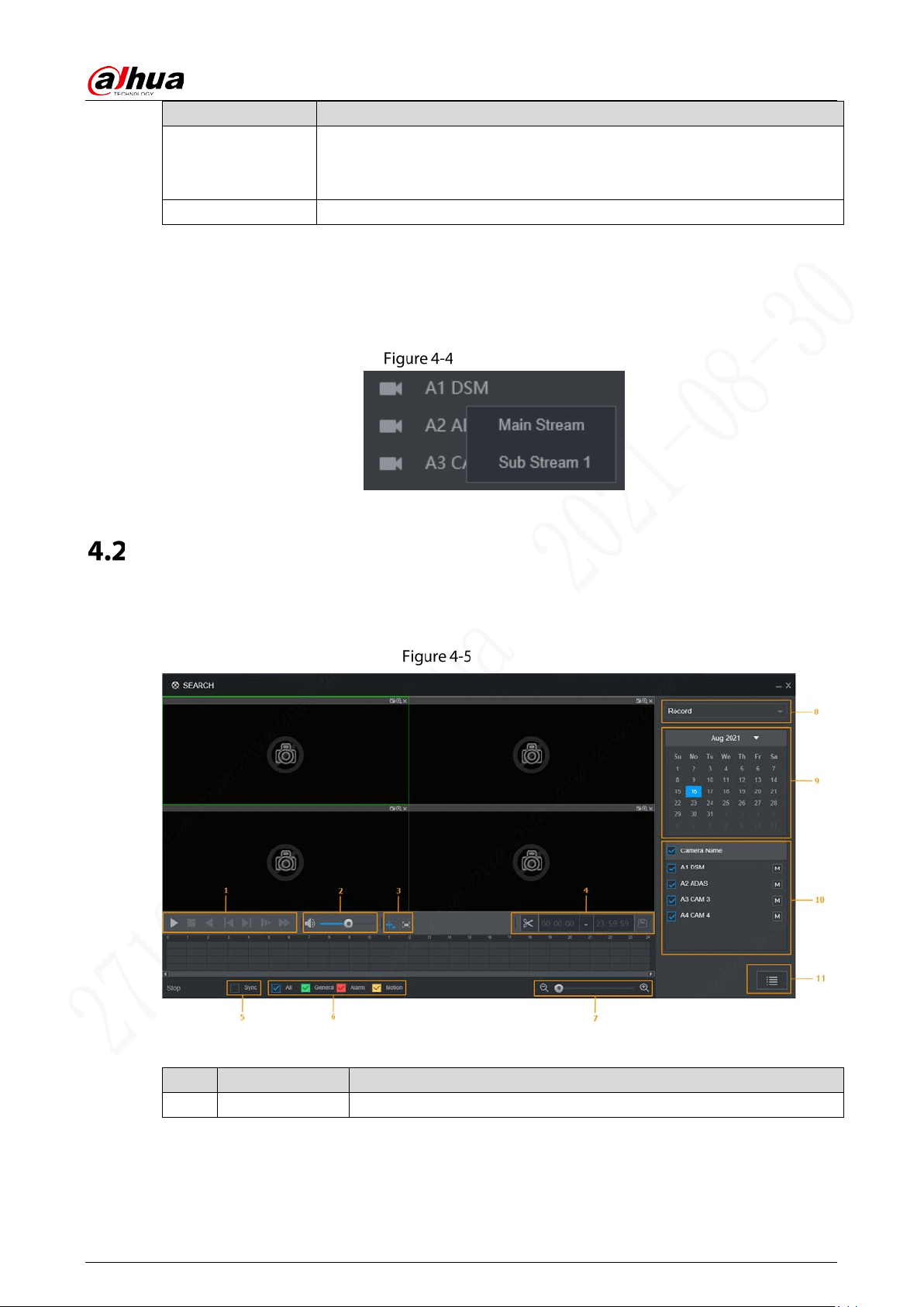
Click any monitoring channel to display its live video on the screen. See Figure 4-3.
Video monitoring screen
Table 4-2 Video monitoring window parameters description
Parameter Description
Device Information
Displays the IP address, channel number, bit stream, and stream type (M
represents main stream, S represents sub stream)
Record
Click this icon to start recording; click it again to stop recording.
The recorded files default storage path is C:\RecordDownload. You can
modify this path if needed. For details, see “5.4.2.4 Storage Path”.
Snapshot
Click this icon to start taking snapshot.
The snapshots default storage path is C:\PictureDownload. You can modify
this path if needed. For details, see “5.4.2.4 Storage Path”.
Sound
Turns on/off audio. If audio function is not enabled in the encode settings,
the monitoring does not give sound.
User’s Manual
32
Parameter Description
Digital Zoom
Click this icon and then hold down the left mouse button to select the area
you want to enlarge. The area is enlarged. Click this icon again or right-click
on the window to exit.
Close Close the live view in the window.
Stream Type
The system supports switching between main stream and sub stream in real-time monitoring window.
See Figure 4-4. For details about stream settings, see “5.4.2 Encode Parameters”.
Stream type
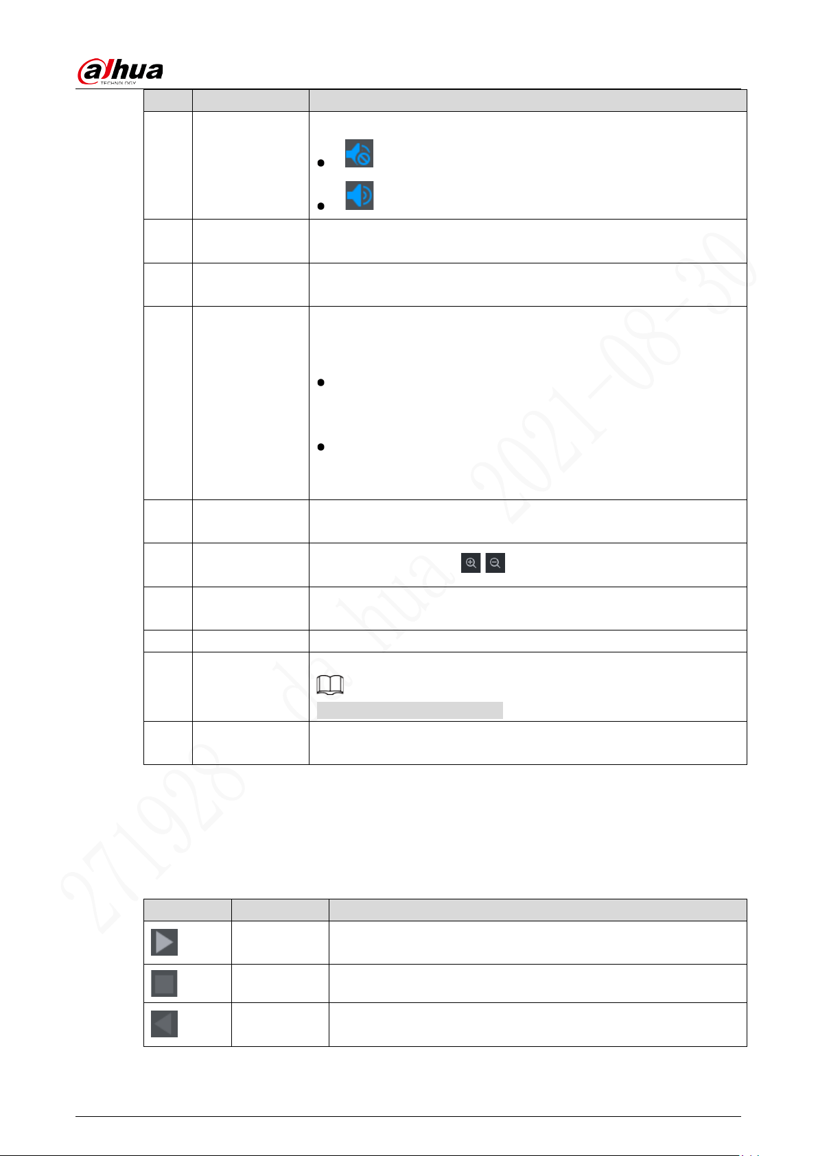
Video Playback
On the Search interface, you can play back or download video recording files.
On the main WEB interface, click Search, and the Search interface is displayed. See Figure 4-5.
Search
Table 4-3 Function bar description
No. Function Description
1 Control Bar For detailed information about control buttons, see “4.2.2 Control Bar”.
User’s Manual
33
No. Function Description
2 Volume Bar
Controls playback volume, including:
means mute mode.
means normal playing and the volume can be adjusted.
3
Full Screen
Button
To play the video recording in full screen.
4
Video Clip
Clip a section of recorded video and save it. See “4.2.4 Clipping
Recording File”.
5 Sync
With Sync selected, when you click in the progress bar to play back the
recordings, the playback time of other channels will sync with the
selected channel in the following ways:
If the playback time of other channels is before the time of the
selected channel, other channels will speed up the playback till
synced with the selected channel.
If the playback time of other channels is after the time of the
selected channel, other channels will pause to wait till synced with
the selected channel.
6 Record Type
The record types include General,Alarm , and Motion. You can select
the type as needed.
7 Time Bar
Move the slider or click / to adjust the time bar.
8 Playback Type
To select the playback type. Only record playback is supported at
present.
9 Calendar Click the date on which you want to play back the recorded video.
10 Channel List
You can set the cameras to focus on.
You can select up to 4 cameras.
11 File List
You can download recorded video by file type or time, and verify the
completeness.
4.2.2 Control Bar
Playback control buttons. For details, see Table 4-4.
Table 4-4 Playback controls bar introduction
Icon Function Description
Play
When this icon displays, it means the video is paused or not being
played. You can click this icon to play the video.
Stop Click this icon to stop playing.
Play
Backward
Click this icon to play the video recording backward.
User’s Manual
34
Icon Function Description
Previous
Frame
Click this icon to jump to the previous frame.
You need to pause the playback before playing the next frame.
Next Frame
Click this icon to jump to the next frame.
You need to click the Stop icon before playing the next frame.
Slow
Click this icon to adjust the slow playback speed. Click to
start slow playback.
Fast
Click this icon to adjust the fast playback speed. Click to start
fast playback.
4.2.3 Playing Back Recorded Video Files
You can play back video recordings by time or file name. During playback, you can conduct the
following operations.
In the channel window, click at the upper right corner and select the area you want to enlarge.
The area is enlarged. Click this icon again or right-click in the window to exit.
Click at the upper right corner to take a snapshot.
Click at the upper right corner to close playback..
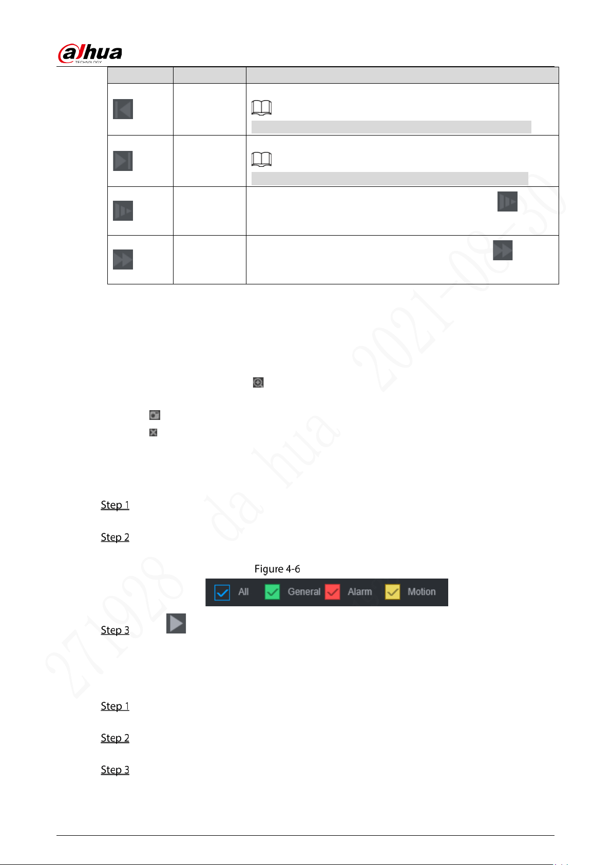
4.2.3.1 Playing Back Video Recordings by Date
Select the date for searching for the video recordings, and set the corresponding channel as
needed.
Select a date with recorded video files, click on the window channel to select a playback
channel, and then select the record type.
Record type
Click to start playing back recorded video.
4.2.3.2 Playing Back Video Recordings by File Name
Select the date for searching for the video recordings, and set the corresponding channel as
needed.
Select a date with recorded video files, click on the window channel to select a playback
channel.
Click File List.
The video recordings are displayed in the list. See Figure 4-7.
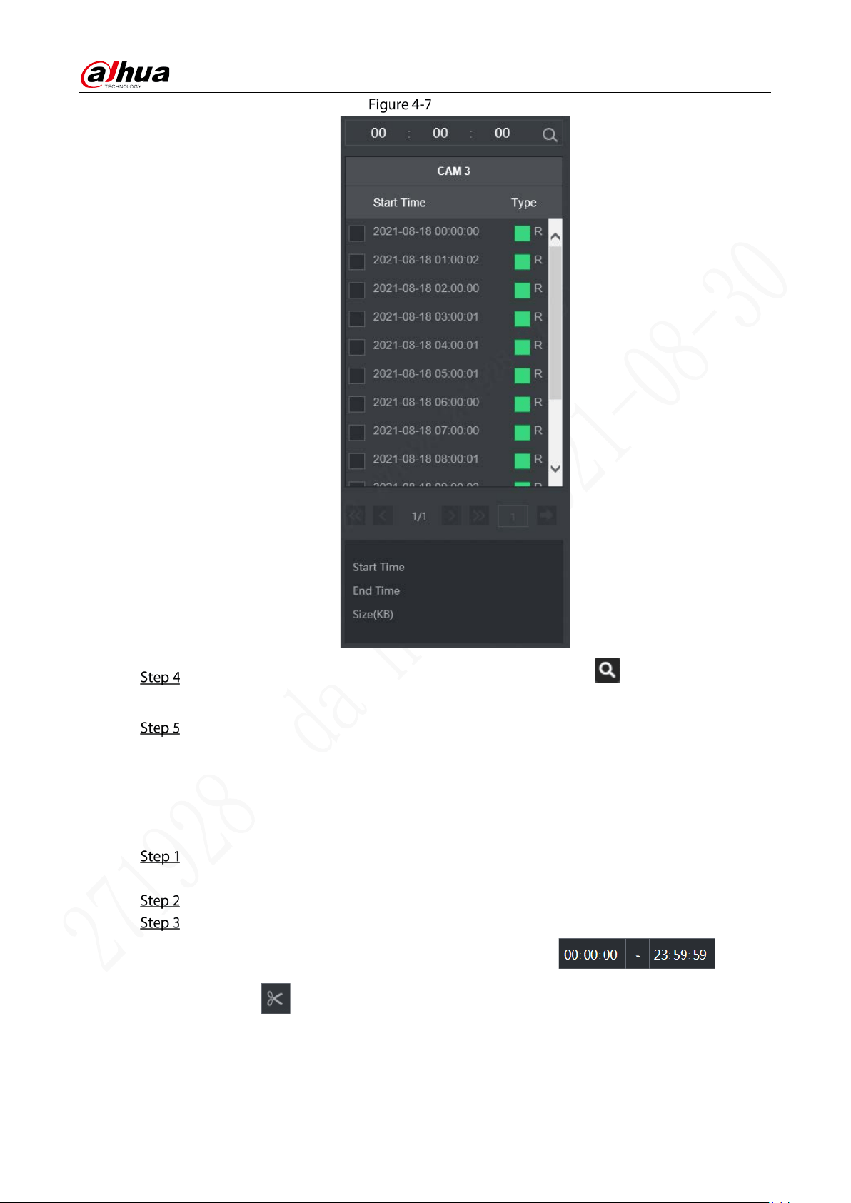
User’s Manual
35
File List
Set the start time of the file to be searched for, and then click . The recording files are
displayed.
Double-click the video recordings to start playback.
4.2.4 Clipping Recording File
Clip a section recorded video file you do of 0 recorded video, and save it to PC.
On the Search interface, select Mode, Date, and Record Type for concentration playback.
The corresponding search result is displayed.
Select a playback window, and then tap.
Capture the video segment you need through the following methods:
Enter the start time and end time you need to edit in .
Click and video clipping frame appears on the time bar. See Figure 4-8. Press the
record edit column (the white column on) and drag to the left or right, to select start time
and end time of clipping.
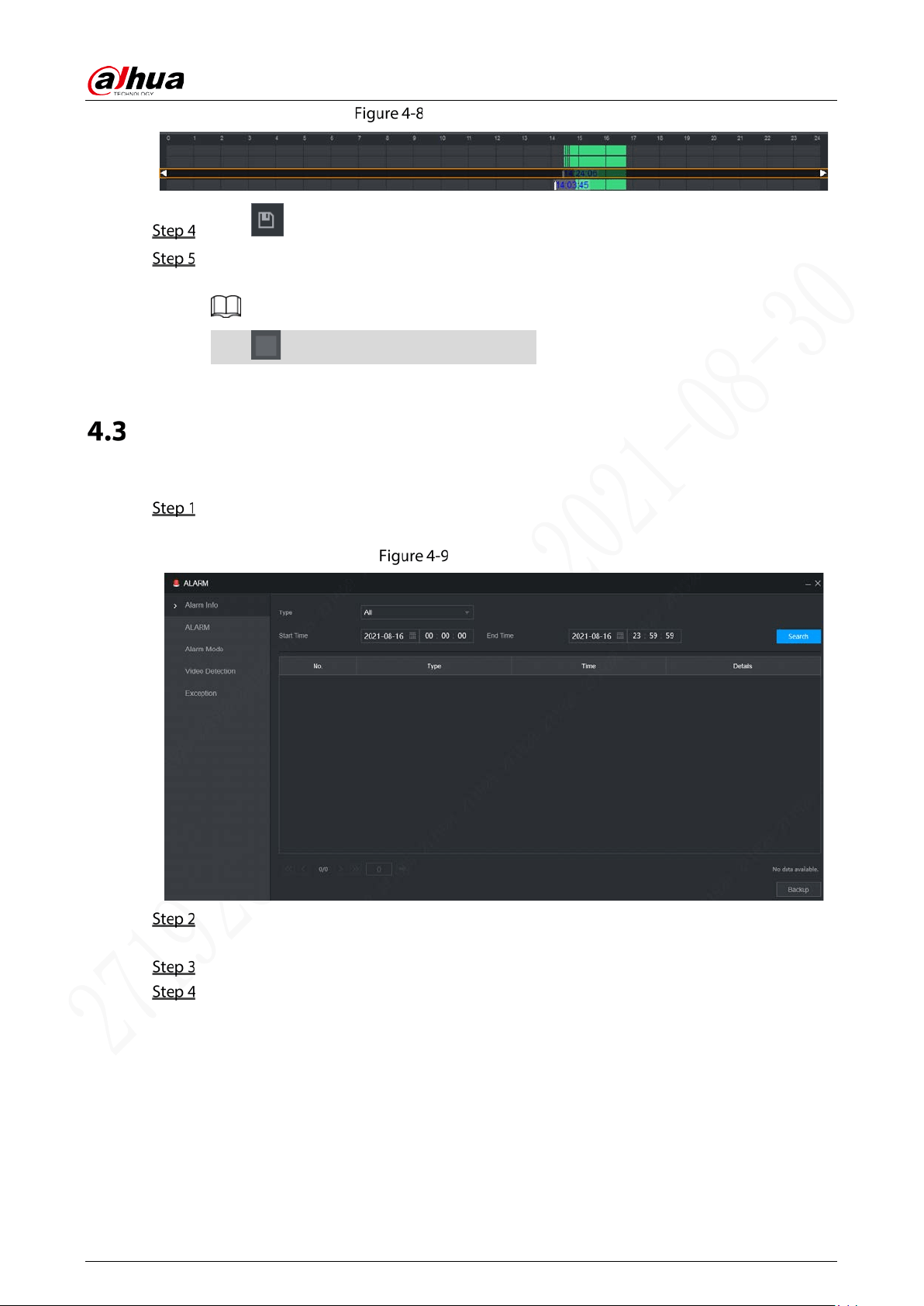
User’s Manual
36
Video clipping frame
Click to select save path.
Click OK.
The system begins to save the record file and displays the saving progress.
Click to stop downloading the recordings.
Alarm Info
You can view the alarm information during a fixed period.
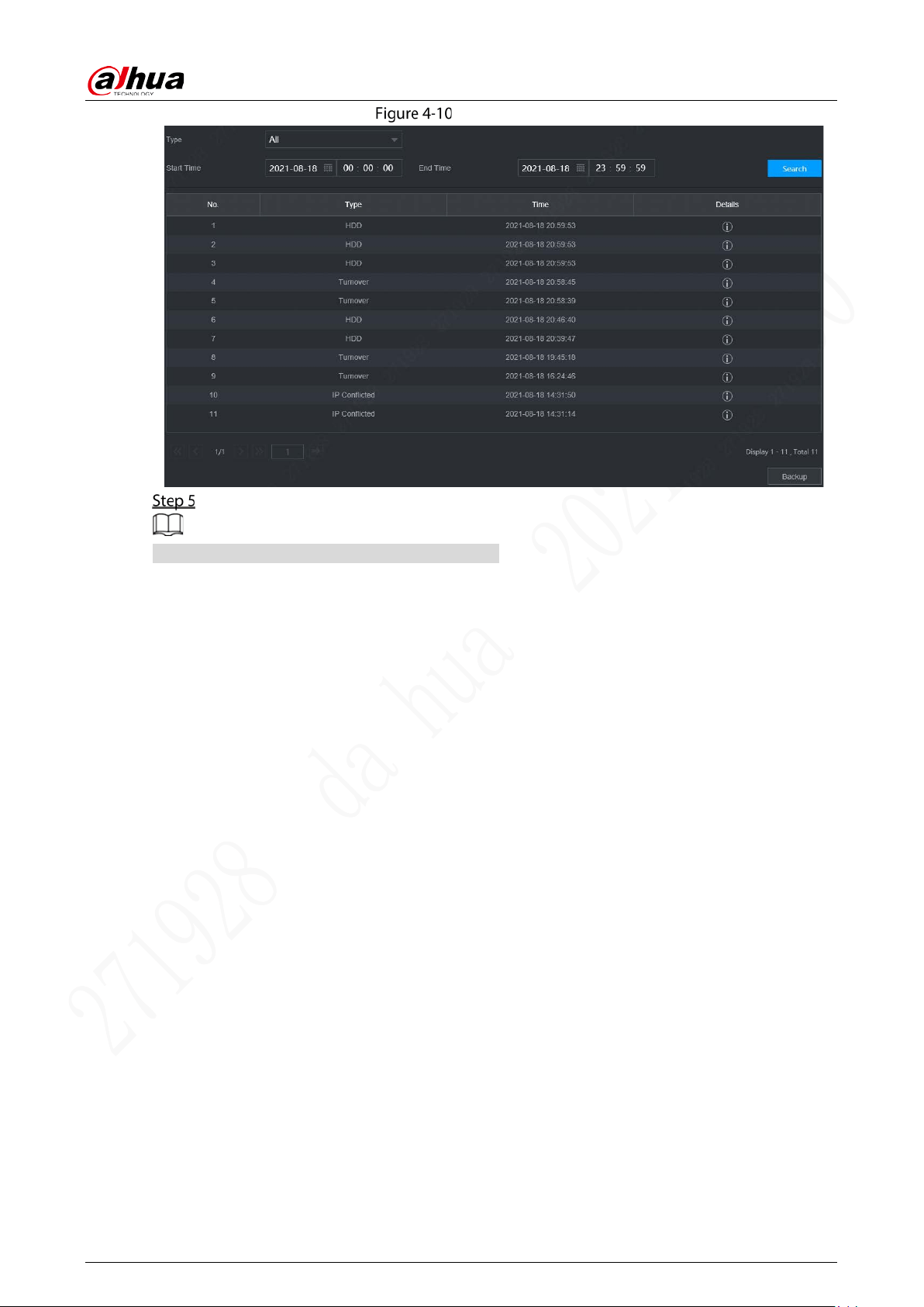
On the main WEB interface, click Alarm > Alarm Info.
The Alarm Info interface is displayed. See Figure 4-9.
Alarm info (1)
Select Type to set the alarm type to be searched for, including All, Motion Detection, Video
Loss, Tampering, Exception, Local Alarm and Intelligent.
Enter the start time and end time.
Click Search.
Alarm information in the set type during the set period is displayed. See Figure 4-10.
User’s Manual
37
Alarm info (2)
Click Backup to back up the obtained alarm information to a local directory.
You need to install relevant controls before backup.

User’s Manual
38
5 System Settings
You can set up system information following instructions on the Local interface or WEB interface. This
section introduces the WEB interface instructions. The Local interface is similar and would not be
elaborated here.
Some functions can only be configured on the Local interface. The actual interface shall prevail.
Some functions are not used in actual operations, so they are not described in detail in the
document.
In this section, when you have configured the settings for a channel, click Copy to apply the
settings to other channels. Click Refresh to display the latest configuration. Click Default to
restore to factory default settings.
Configuring Alarm Events
Alarm settings include the setting of video detection, alarm, exception and alarm mode.
5.1.1 Video Detection
Video detection includes motion detect, video loss, and video tampering. This function detects the
abnormal changes and triggers alarms.
5.1.1.1 Video Motion
When the moving object appears and moves fast enough to achieve the preset sensitivity value, the
system triggers an alarm and alarm linkage.
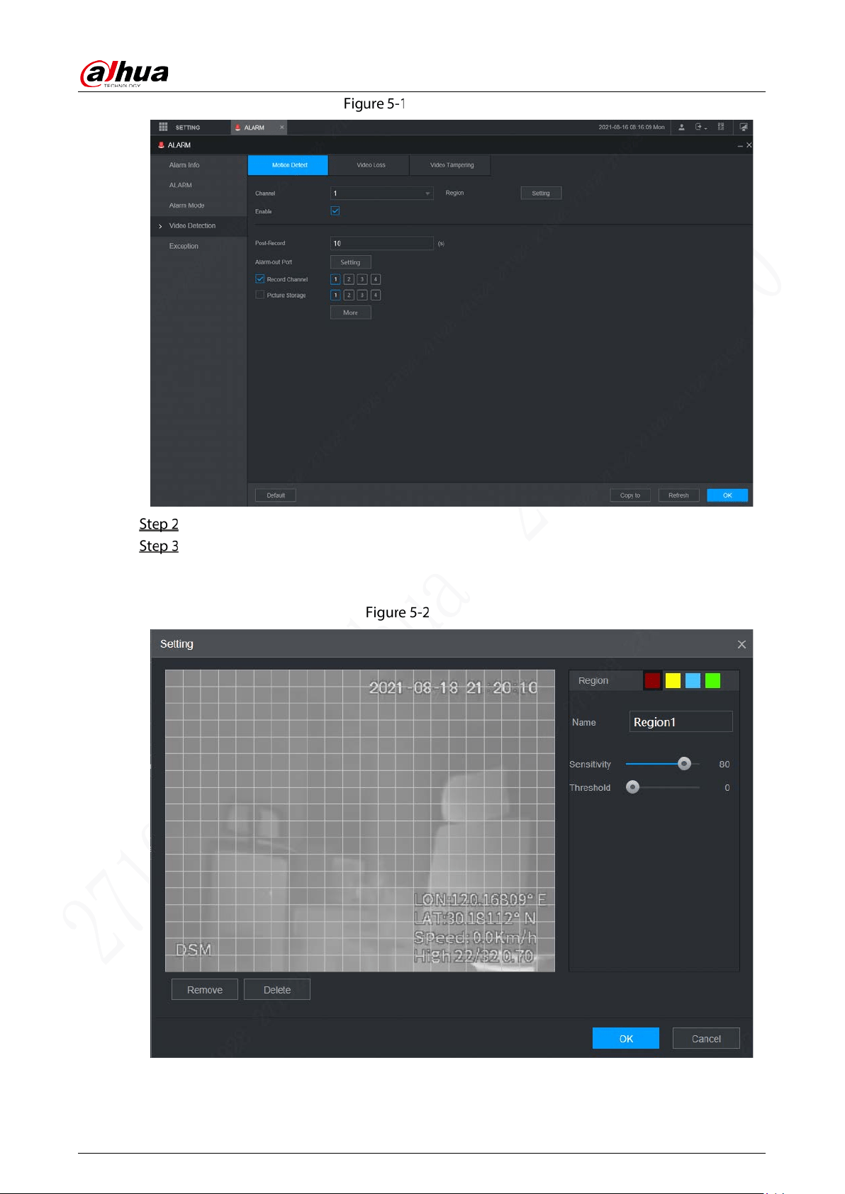
On the main WEB interface, select Alarm > Video Detection > Motion Detect.
The Motion Detect interface is displayed. See Figure 5-1.
User’s Manual
40
The higher the sensitivity value is, the easier the motion detection is triggered; the lower
the threshold is, the easier the motion detection is triggered. By default, the whole video
image is for motion detection.
Different colors represent different regions; you can define different motion detection
areas for each region.
3) Hold down the left button of the mouse, drag to select the region to be detected, and
set up its sensitivity and threshold value.
Channel alarm events: As long as any one of the four regions triggers alarm, the channel
that houses the region will give alarm.
4) Click OK to finish configuration.
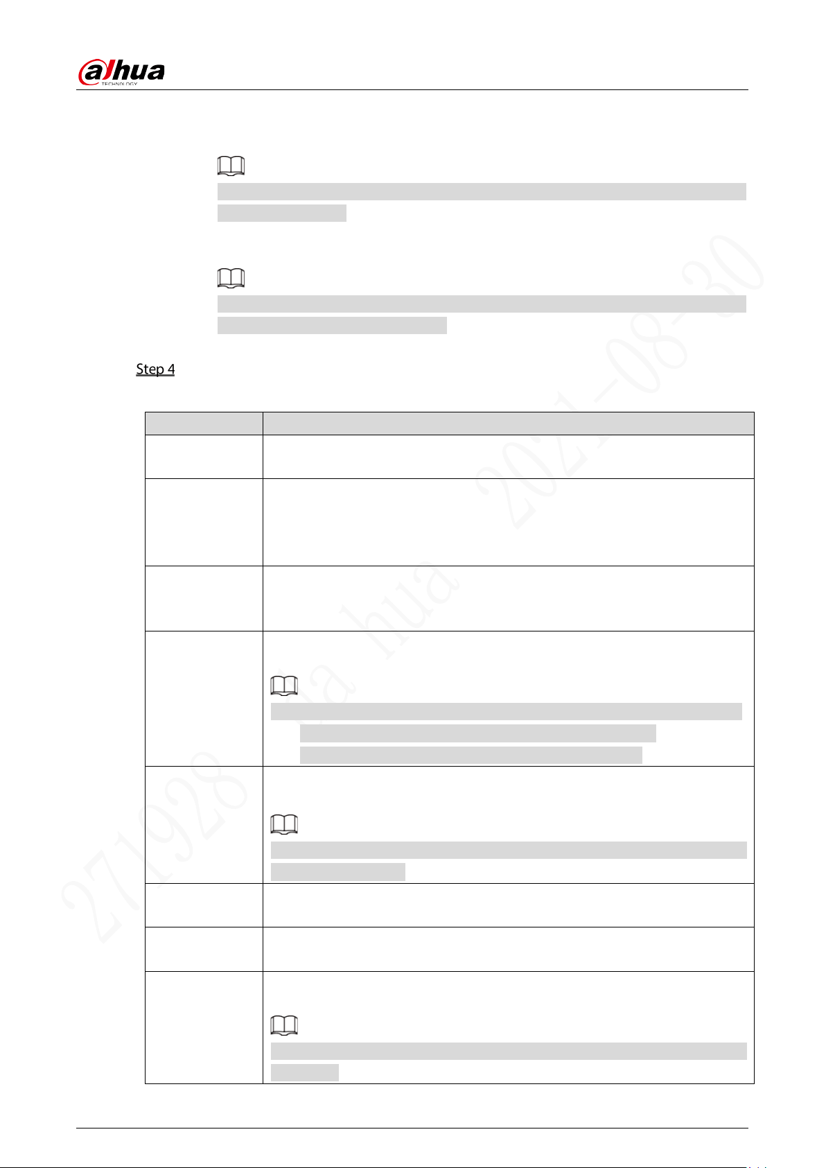
Configure alarm linkage parameters. See Table 5-1 for details.
Table 5-1 Alarm linkage parameters description
Parameter Description
Post-Record
The video recording will not stop until the record delay time you set has
passed.
Alarm-out Port
Connect with an alarm device (such as an alarm light or siren) on the alarm
output interface, click Setting to set the alarm output device, and activate the
alarm linkage output port. When an alarm event takes place, the system can
trigger corresponding alarm output devices.
Post-Alarm
Click Setting under Alarm Output to set the delay.
Set a length of time during which the device continues alarm output after the
alarm ends.
Record Channel
Select the Record Channel check box and select a record channel(s), when an
alarm event occurs, the corresponding channel starts recording automatically.
Two more conditions must be satisfied before alarm recording function works:
Motion detect recording is enabled. See “5.4.2.2 Snapshot”.
Auto recording is enabled. See “3.6 Configuring Record ”.
Picture Storage
Select the corresponding check box and set the channel. When an alarm event
occurs, the corresponding channel starts capturing automatically.
You can also configure the frequency, size, and quality of snapshot. For details,
see “5.4.2.2 Snapshot.”
Anti-dither
Click More to set Anti-dither time.
The system records only one event during this period.
Log
Click More, and select the corresponding check box to enable the device to
create a local alarm log when an alarm event occurs.
Send Email
Click More, and select the corresponding check box. When an alarm event
occurs, the system sends email to the specified mailbox.
Set your e-mail first before enabling this function. See “5.5.4 Email” for detailed
operations.
User’s Manual
41
Click OK.
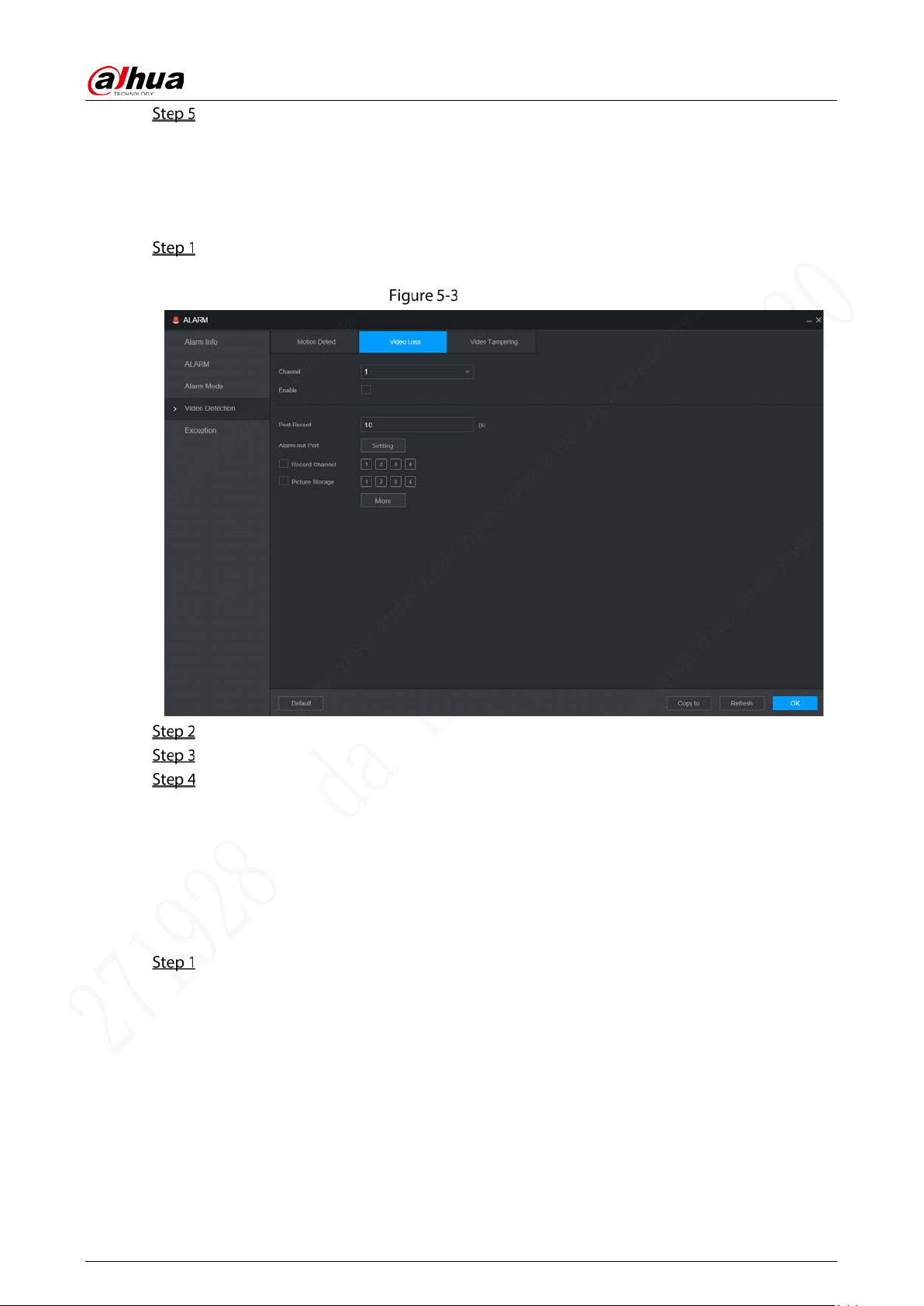
5.1.1.2 Video Loss
When video loss occurs, the system triggers an alarm and configured actions.
On the main WEB interface, select Alarm > Video Detection > Video Loss.
The Video Loss interface is displayed. See Figure 5-3.
Video Loss
Select Channel and select Enable to enable the video loss detect function for the channel.
Configure alarm linkage parameters. See Table 5-1 for details.
Click OK.
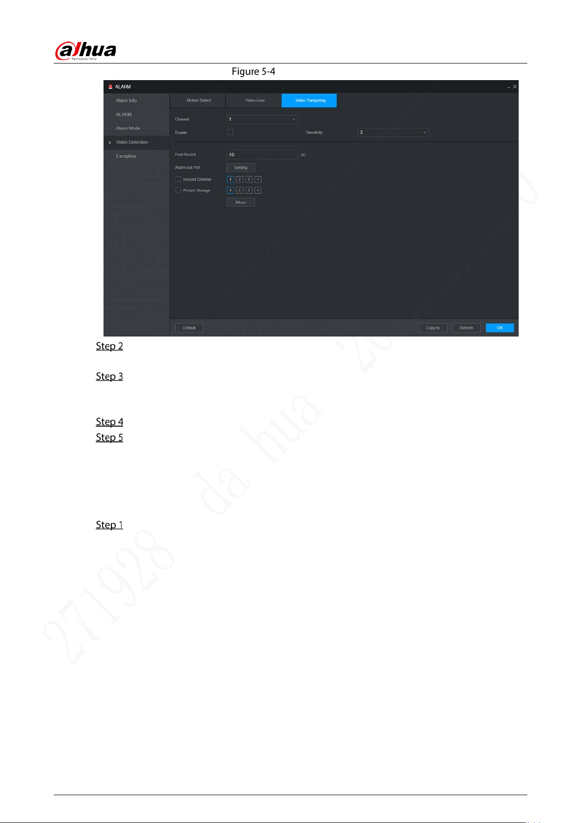
5.1.1.3 Video Tampering
When the camera lens is covered, or the video is displayed in a single color because of the causes such
as sunlight status, the monitoring cannot be continued normally, and in this case, the system activates
alarm and links the configured actions.
On the main WEB interface, select Alarm > Video Detection > Video Tampering.
The Video Tampering interface is displayed. See Figure 5-4.
User’s Manual
42
Video tampering
Select Channel and select Enable to enable the video tampering detect function for the
channel.
Set the sensitivity of detection.
The higher the sensitivity, the easier it is to detect a moving object, but the false alarm rate
might increase.
Configure alarm linkage parameters. See Table 5-1 for details.
Click OK.
5.1.2 Alarm Input
Select different types of input according to alarm sources and set alarm output mode.
On the main WEB interface, select Alarm > Alarm.
The Alarm interface is displayed. See Figure 5-5.

User’s Manual
43
Alarm
Local: The alarm signal detected by the alarm input port on the device.
Select the channel and select Enable.
Configure parameters. For details, see Table 5-2.
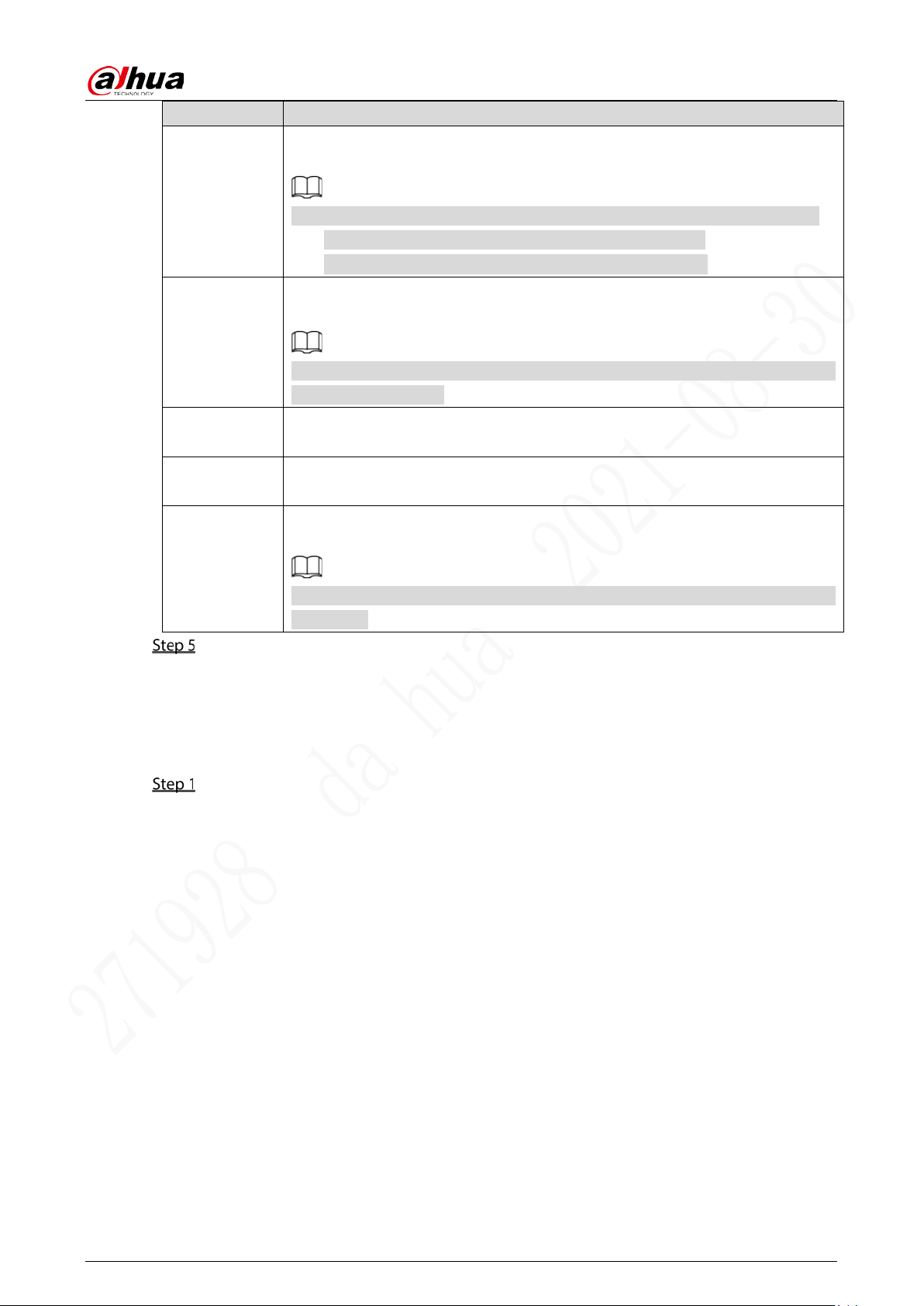
Table 5-2 Alarm parameters description
Parameter Description
Alarm Name Enter a customized alarm name.
Device Type
If the Event Type is Local Alarm, configure this parameter.
NO: The alarm signal is disconnected normally. The alarm is triggered when
alarm signal is connected.
NC: The alarm signal is connected normally. The alarm is canceled when
alarm signal is disconnected.
Overlay
Select the Overlay check box to overlay alarm names onto channel images.
Linkage
If the Event Type is Local Alarm, configure this parameter.
If the alarm signal is 12V/24V voltage, select High as the triggering mode; if the
alarm signal is ground voltage, select Low as the triggering mode.
Post-Record The video recording will not stop until the record delay time you set has passed.
Alarm-out Port
Connect alarming devices (for example lights and sirens) to the alarm output
ports, click the check box, when an alarm is triggered, alarms will be sent to
alarm output devices.
Post-Alarm
Click Setting under Alarm-out Port to set the delay time.
Set a length of time during which the device continues alarm output after the
alarm ends.
User’s Manual
44
Parameter Description
Record
Channel
Select the Record Channel check box and select a record channel(s), when an
alarm event occurs, the corresponding channel starts recording automatically.
Two more conditions must be satisfied before alarm recording function works:
Alarm recording is enabled. See “3.7.1 Record Schedule”.
Auto recording is enabled. See “3.6 Configuring Record ”.
Picture Storage
Select the corresponding check box and set the channel. When an alarm event
occurs, the corresponding channel starts capturing automatically.
You can also configure the frequency, size, and quality of snapshot. For details,
see “5.4.2.2 Snapshot”.
Anti-dither
Click More to set the debouncing time.
The system records only one alarm input event during the configured period.
Log
Click More, and select the corresponding check box to enable the device to
create a local alarm log when an alarm event occurs.
Send Email
Click More, and select the corresponding check box. When an alarm event
occurs, the system sends email to the specified mailbox.
Set your e-mail first before enabling this function. See “5.5.4 Email” for detailed
operations.
Click OK.
5.1.3 Exception
You can configure the ways to handle the device when errors occur.
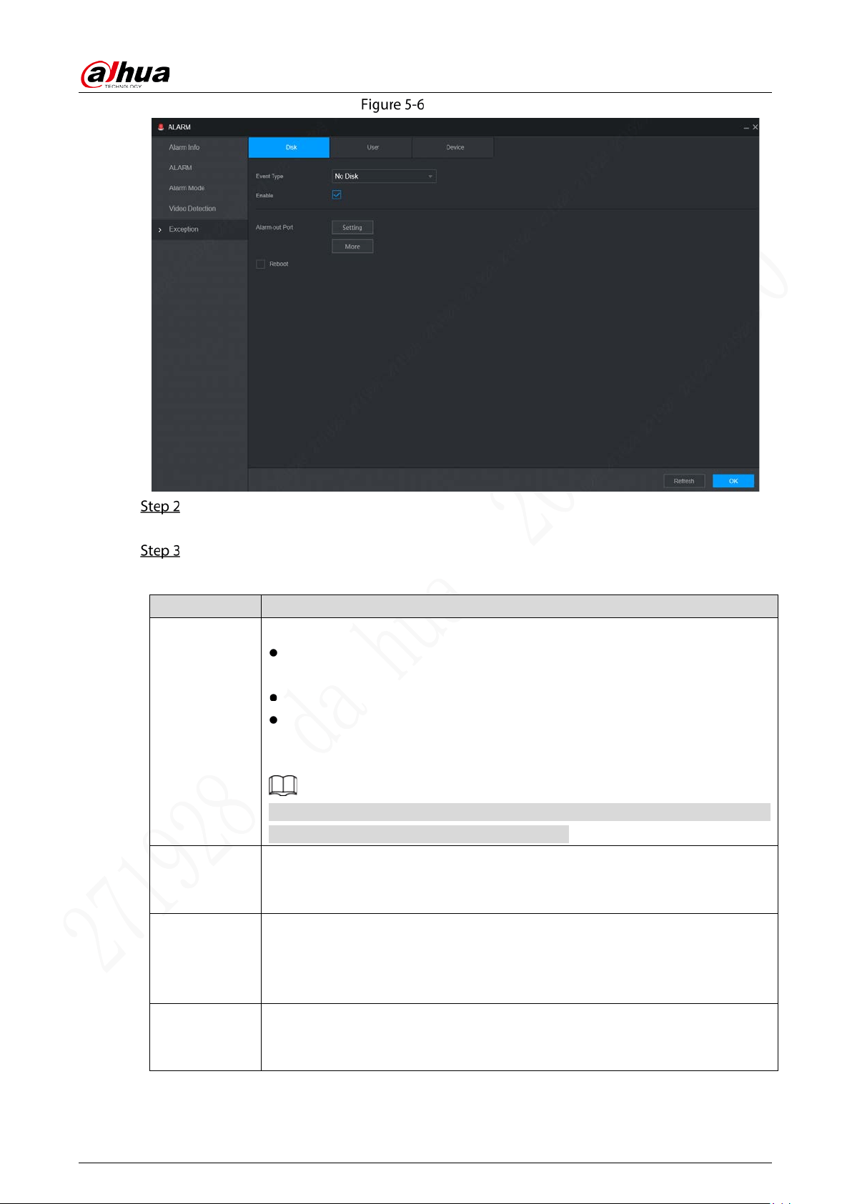
On the main WEB interface, select Alarm > Exception.
The Exception interface is displayed. See Figure 5-6.
User’s Manual
45
Exception
Select the event type, and select Enable to enable the handling of corresponding abnormal
events.
Configure parameters. For details, see Table 5-3.
Table 5-3 Abnormality parameters description
Parameter Description
Event Type
You can configure the corresponding abnormal events on following three tabs.
Disk: To set the ways to handle abnormal Disk events, including No Disk, HDD
Error, Low Space.
User: Includes illegal login.
Device: To set the ways to handle abnormal device events, including High
Temperature, Battery Low Space, Network Security Exception, Over Speed,
Low Speed, Collision, Turnover, and ACC Power Off.
The supported event type might be different depending on the model you
purchased, and the actual interface shall prevail.
Capacity Limit
Select Disk tab, and if the Event Type is Low Space, configure this parameter.
You can set the percentage of HDD remaining space. When HDD remaining
space is lower than this percentage, an alarm will occur.
Attempt(s)
If the Event Type is Illegal Login, configure this parameter.
The maximum number of allowed password input errors during user login. If the
number of password input errors reaches this value, the user account will be
locked.
Lock Time
If the Event Type is Illegal Login, configure this parameter.
If the number of password input errors reaches this value, the user account will
be locked.
User’s Manual
46
Parameter Description
Max
Temperature
If the Event type is High Temperature, configure this parameter.
Enter the upper limit of device temperature. The alarm is triggered when the
device temperature exceeds this value.
Low Than
If Event Type is Battery Low Space, configure this parameter.
The supply voltage to the device from the vehicle and the percentage of
available supply voltage capacity. When the vehicle is in ACC Off, and the
voltage supplied to the device is less than the percentage of available capacity,
the system triggers an alarm.
Auto
Battery Voltage
Max Speed
If the Event type is Over Speed, configure this parameter.
The upper limit of vehicle speed. When the vehicle speed exceeds this value, the
system triggers an alarm.
Min Speed
If Event Type is Low Speed, configure this parameter.
The lowest limit of vehicle speed. When the vehicle speed is lower than this
value, the system triggers an alarm.
Alarm-out Port
Connect alarming devices (for example lights and sirens) to the alarm output
ports, click the check box, when an alarm is triggered, alarms will be sent to
alarm output devices.
Post-Alarm
Click Setting under Alarm-out Port to set the delay time.
Set a length of time during which the device continues alarm output after the
alarm ends.
Send Email
Click More, and select the corresponding check box. When an alarm event
occurs, the system sends email to the specified mailbox.
Set your e-mail first before enabling this function. See “5.5.4 Email” for detailed
operations.
Log
Click More, and select the corresponding check box to enable the device to
create a local alarm log when an alarm event occurs.
Reboot
Select the Reboot check box. If No HDD alarm occurs, the system restarts within
three minutes.
Click OK.
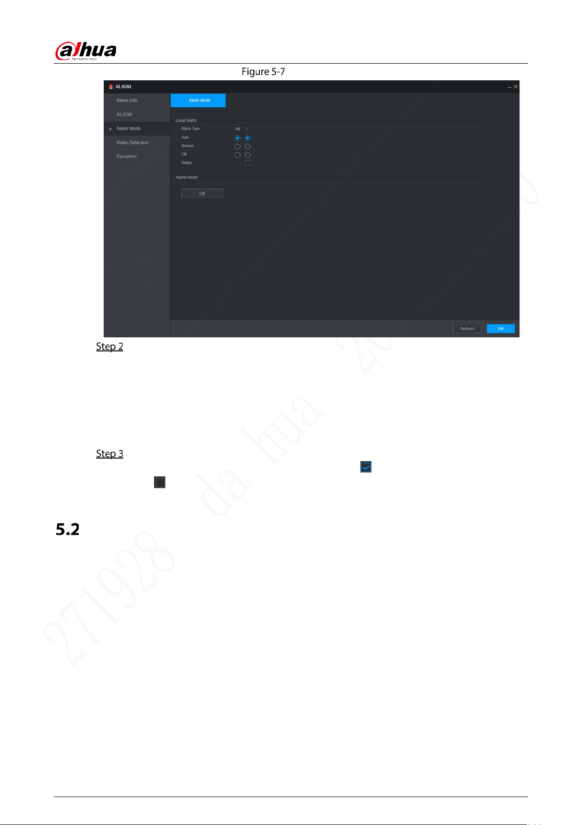
5.1.4 Alarm Output
Set alarm mode.
On the main WEB interface, select Alarm > Alarm Mode.
The Alarm Mode interface is displayed. See Figure 5-7.
User’s Manual
47
Alarm Mode
Select alarm mode.
Auto: After the alarm linkage is configured, when an alarm event occurs, the
corresponding alarm-out port generates alarm.
Manual: After the alarm linkage is configured, no matter whether there is an alarm event
occurs, the corresponding alarm-out port keeps generating alarm.
Off: After the alarm linkage is configured, no matter whether there is an alarm event
occurs, the corresponding alarm-out port never generate alarm.
Click OK.
Status: Indicates the status of each alarm-out port. indicates there is an alarm output,
and indicates there is not.
Configuring AI Plan
AI solution mainly contains active and safe drive. Only when the smart solution is enabled and set can
the corresponding function take effect.
ADAS: Advanced Driver Assistance System for Lane Departure Warning, Headway Monitoring
Warning and Forward Collision Warning, and alarm linkage is triggered and reported to the
platform.
DSM: The system can analyze and process the driver behavior information collected by cameras,
and detect actions such as lowering head, yawning, smoking, looking around, and duration
without driver.
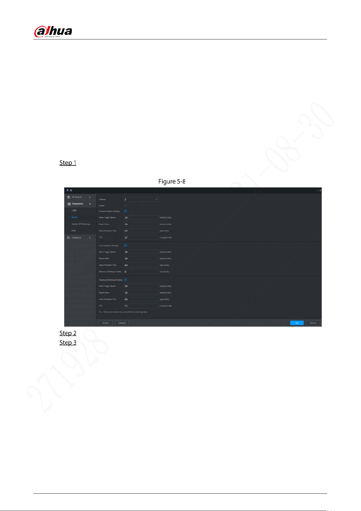
5.2.1 ADAS
ADAS alarms mainly include Forward Collision Warning, Lane Departure Warning and Headway
Monitoring Warning.
User’s Manual
48
Prerequisites
Access to cornering lamp signal in advance: Alarm Input_2 (turn left), Alarm Input_3 (turn right).
After the cornering lamp of the vehicle is turned on, no Lane Departure alarm will be triggered.
Config: Driver assistance relies on the camera installation location, and cannot be used until the
calibration is completed. Try to install the camera in the middle of the windshield. When
configuring parameters, measure the width of the vehicle, the height of the camera, and the
distance from the camera to the vehicle head in advance. After the vehicle travels for a certain
period of time, the device will automatically calibrate the position.
Procedure
On the main WEB interface, click AI > Parameters > ADAS.
The ADAS interface is displayed. See Figure 5-8.
ADAS
Click Enable and OK to enable the ADAS alarm.
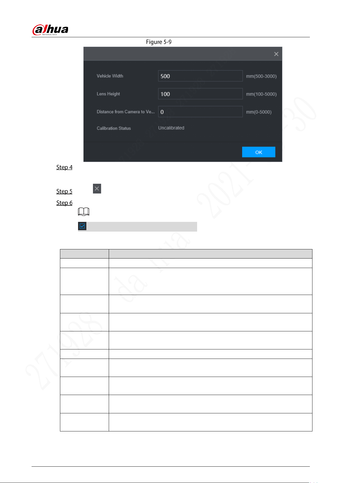
Click Calibrate.
The Calibrate interface is displayed. See Figure 5-9.
User’s Manual
49
Calibrate
Enter the vehicle width, the lens height and the distance from the camera to the vehicle head,
and click OK to complete the calibration.
Click to return to the Figure 5-8 interface.
Configure parameters. For details, see Table 5-4.
means the corresponding alarm is enabled.
Table 5-4 ADAS parameters description
Parameter Description
Channel ADAS is fixed to channel 2.
Forward
Collision
Warning
Give a warning if it is possible to collide with the vehicle in the front.
Alarm Trigger
Speed
The speed at which the Forward Collision Warning is triggered: The range is
30km/h–200km/h.
Report Alarm
The speed at which the Forward Collision Warning is uploaded: The range is
30km/h–200km/h.
Alarm Protection
Time
Continuous alarm time: The range is 1s–65536s.
TTC Time to collision: The range is 0s–10s.
Lane Departure
Warning
Alarm when the vehicle directly changes the lane without turning on the left
or right cornering lamp.
Alarm Trigger
Speed
The speed at which the Lane Departure Warning is triggered: The range is
30km/h–200km/h.
Report Alarm
The speed at which the Lane Departure Warning is uploaded: The range is
30km/h–200km/h.
Alarm Protection
Time
Continuous alarm time: The range is 1s–65535s.
User’s Manual
50
Parameter Description
Distance of
Driving on Solid
Line
Set the distance of driving on solid line: The range is -30cm–30cm.
Headway
Monitoring
Warning
Alarm when the vehicle is too close to the vehicle in the front.
Alarm Trigger
Speed
The speed at which the Headway Monitoring Warning is triggered: The range is
30km/h–200km/h.
Report Alarm
The speed at which the Headway Monitoring Warning is uploaded: The range
is 30km/h–200km/h.
Alarm Protection
Time
Continuous alarm time: The range is 1s–65535s.
TTC Time to collision: The range is 0s–10s.
Click OK.
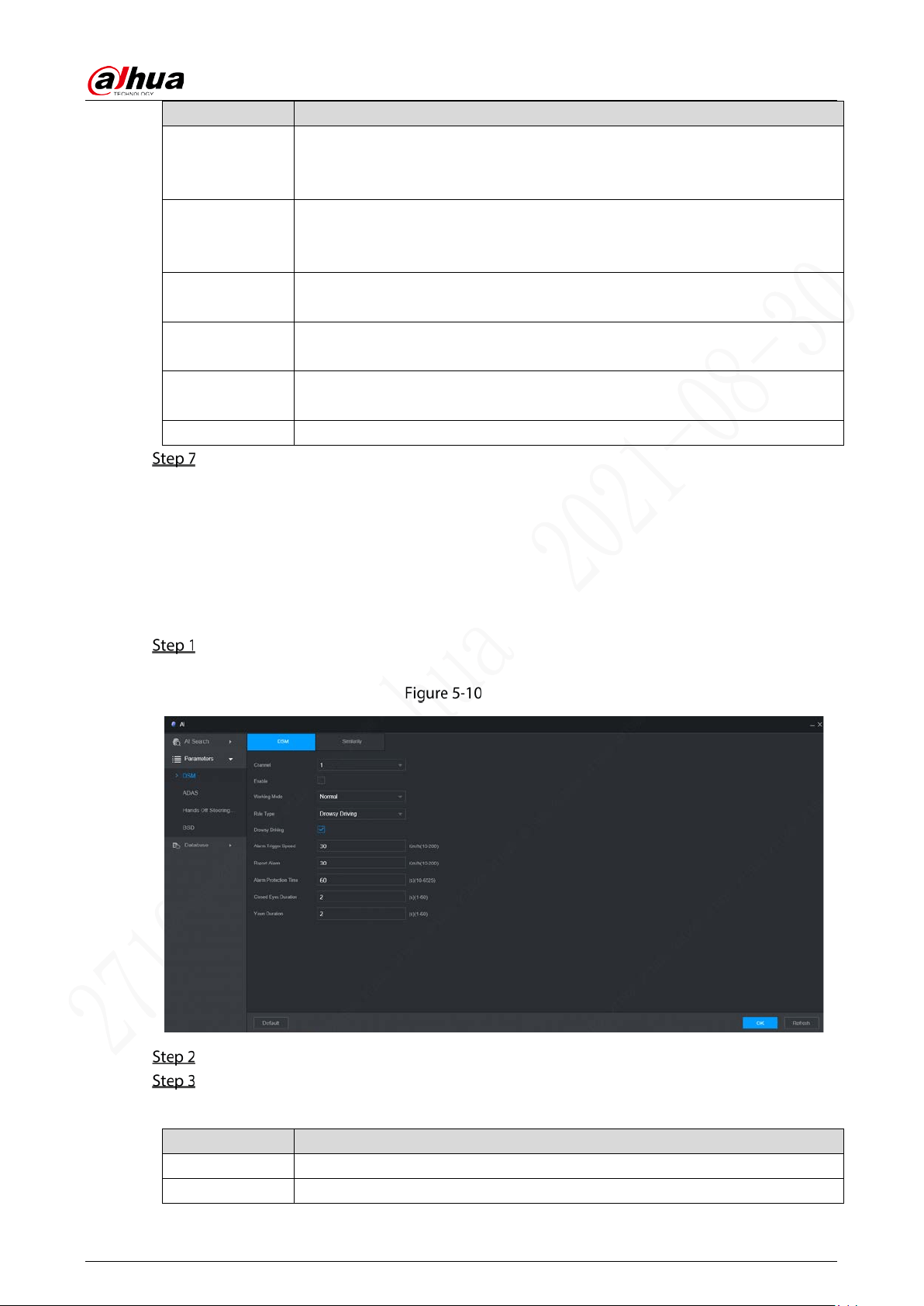
5.2.2 DSM
DSM alarms mainly include drowsy driving, distracted driving, calling, no driver, wearing IR blocking
sunglasses, smoking, lens tampering, and unbelted Alarm. After being triggered, these alarms require
voice broadcast and need to be uploaded to the platform.
On the main WEB interface, click AI > Parameters > DSM.
The DSM interface is displayed. See Figure 5-10.
DSM
Click Enable to enable the DSM alarm.
Configure parameters. For details, see Table 5-5.
Table 5-5 Parameters description
Parameter Description
Channel DSM is fixed to channel 1.
Working Mode Working modes include normal mode and test mode.
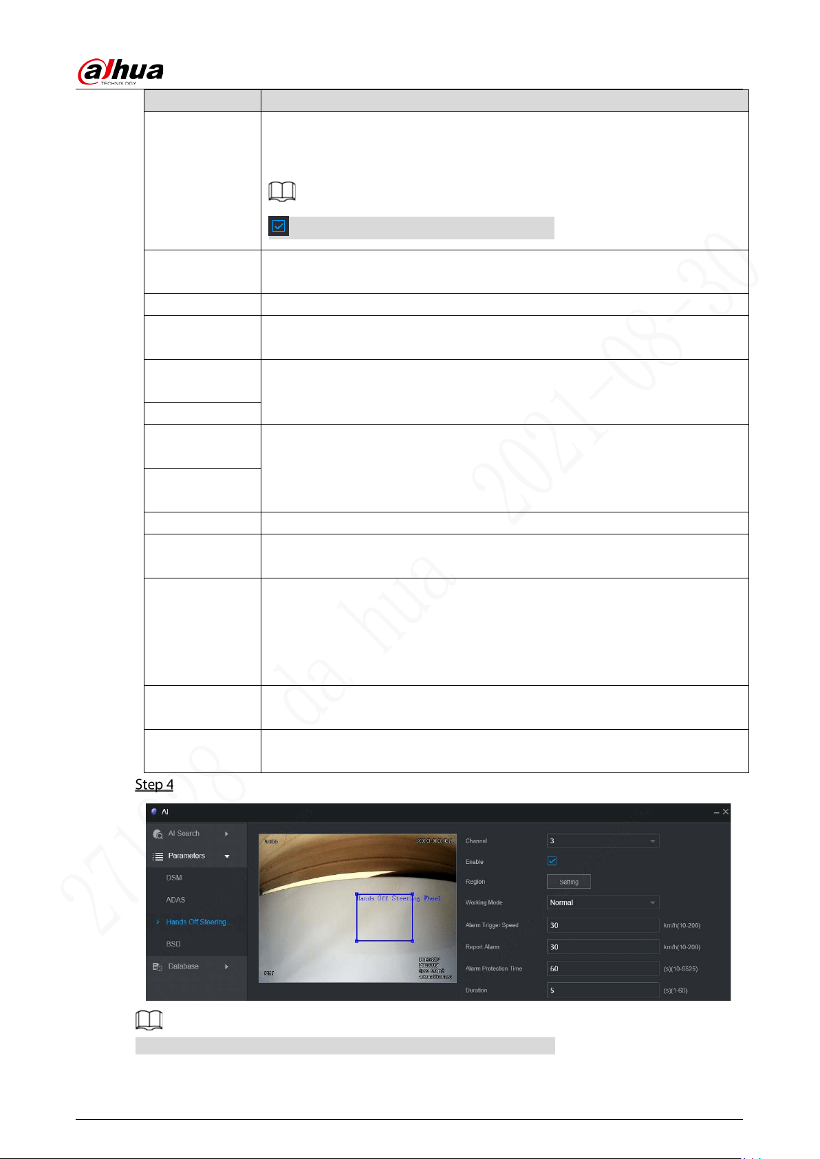
User’s Manual
51
Parameter Description
Rule Type
For alarm rules, you can select drowsy driving, distracted driving, calling, no
driver, wearing IR blocking sunglasses, smoking, lens tampering, and unbelted
Alarm.
means the corresponding alarm is enabled.
Alarm Trigger
Speed
The speed at which the alarm is triggered: The range is 30km/h–200km/h.
Report Alarm The speed at which the alarm is uploaded: The range is 30km/h–200km/h.
Alarm Protection
Time
Continuous alarm time: The range is 1s–65536s.
Closed Eyes
Duration
Setting is necessary when the rule type is Drowsy Driving: The range is 1s–
10s.
Yawn Duration
Lowering Head
Duration
Setting is necessary when the rule type is Distracted Driving: The range is 1s–
10s.
Looking around
Duration
Calling Duration
Setting is necessary when the rule type is Calling: The range is 1s–10s.
Duration
without Driver
Setting is necessary when the rule type is No Driver: The range is 2s–10s.
Duration of
Wearing
Infrared-
blocking
Sunglasses
Setting is necessary when the rule type is Wearing IR Blocking Sunglasses:
The range is 1s–10s.
Smoking
Duration
Setting is necessary when the rule type is Smoking: The range is 1s–10s.
Tampering
Duration
Setting is necessary when the rule type is Lens Tampering: The range is 1s–
10s.
Click OK.
Select a channel from Channel 3 to Channel 4 to enable the detection.
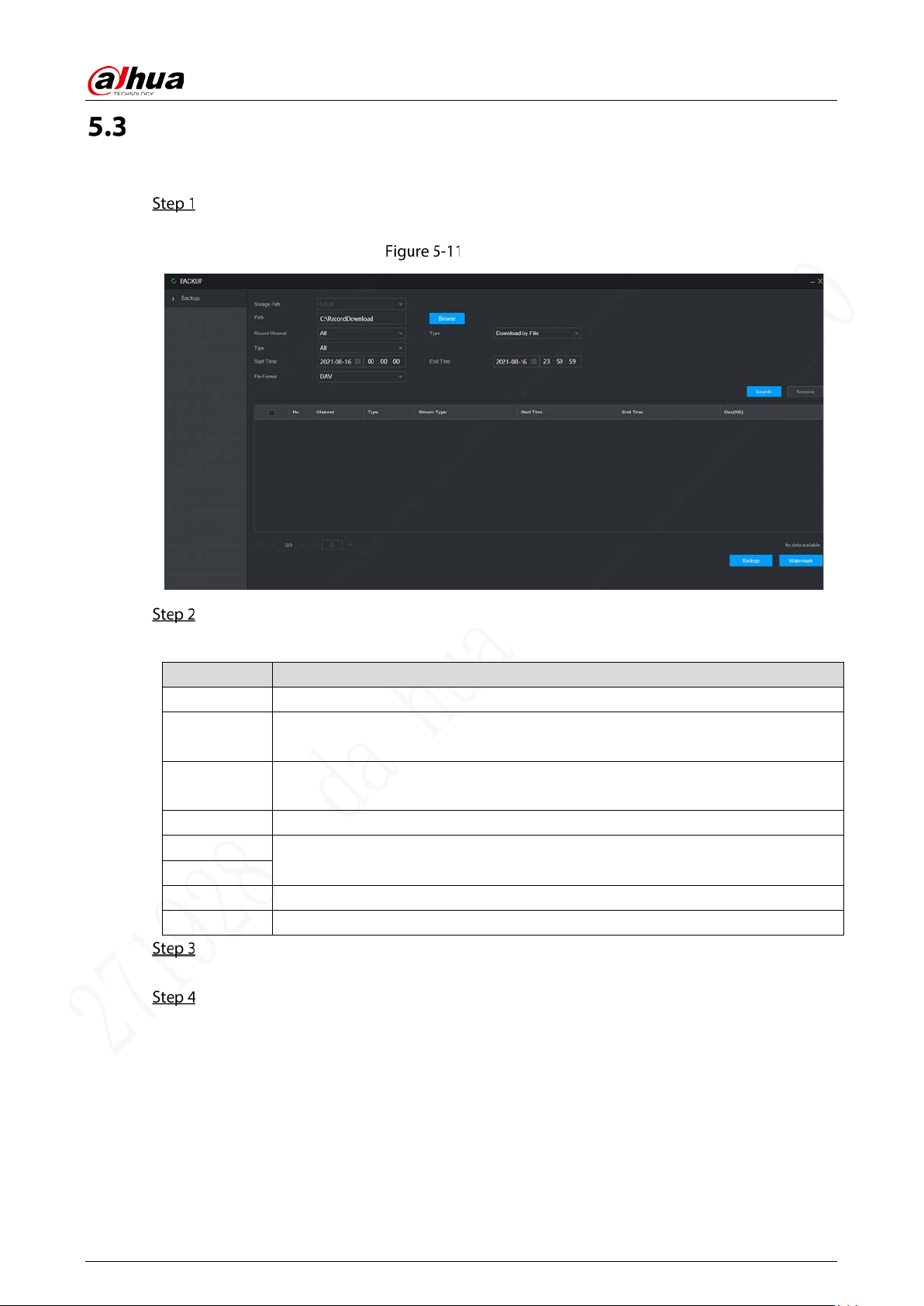
User’s Manual
52
File Backup
You can backup video recordings and images.
On the main WEB interface, click Backup.
The Backup interface is displayed. See Figure 5-11.
Backup (1)
Configure parameters. For details, see Table 5-6.
Table 5-6 Backup parameters
Parameter Description
Storage Path Only local path is supported.
Path
File backup path is C:/RecordDownload by default.
Click Browse to set the backup path as needed.
Record
Channel
Select the channel you want to back up.
Type Select the backup type, including download by file and download by time.
Start time
Set the file backup period.
End Time
File Format Select the backup file format, including DAV and MP4.
Type Select the record type, including Alarm, Motion, M&A, Gennral, Picture, and All.
Click Search.
The obtained files are displayed.
Select the file that you want to back up, and click Backup.
The Backup button is changed to Download now. See Figure 5-12.
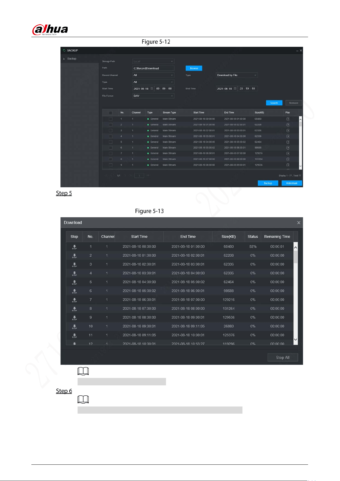
User’s Manual
53
Backup (2)
Click View Download.
The View Download interface is displayed. See Figure 5-13.
View Download
Click Stop All to stop downloading.
(Optional) Select the file that you want to verify, and click Watermark.
Watermark can be used to verify whether the record file is falsified.
The verifying progress and result are displayed.
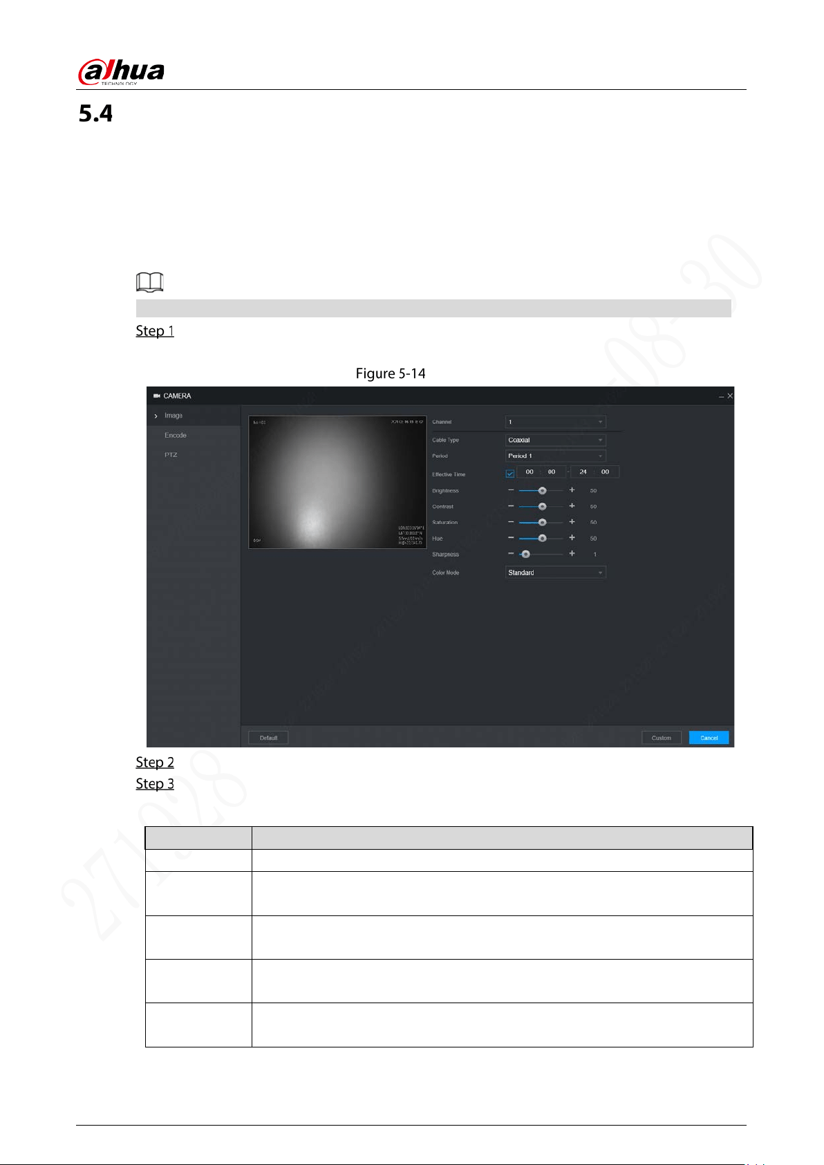
User’s Manual
54
Configuring Camera Parameter
You can set camera properties and encode parameters.
5.4.1 Camera Properties
You can set up the camera property parameters of the channel.
Different cameras correspond to different property parameters. The actual parameters shall prevail.
Select Setting > Camera > Image.
The Image interface is displayed. See Figure 5-14.
Image
Select a Channel.
Configure parameters. For details, see Table 5-7.
Table 5-7 Image setting parameters description
Parameter Description
Cable Type The cable type is fixed to coaxial.
Period
Select the period. There are two Periods for you.You should set up the Effective
Time for different periods.
Brightness
Adjusts the image brightness through linear mode. The bigger the value is, the
brighter the image will become.
Contrast
Adjust the image contrast. The bigger the value is, the more obvious the contrast
between the light area and dark area will become.
Saturation
Adjusts the color darkness. Adjust the saturation according to the actual
situation. The bigger the value, the lighter the color of the image will become.
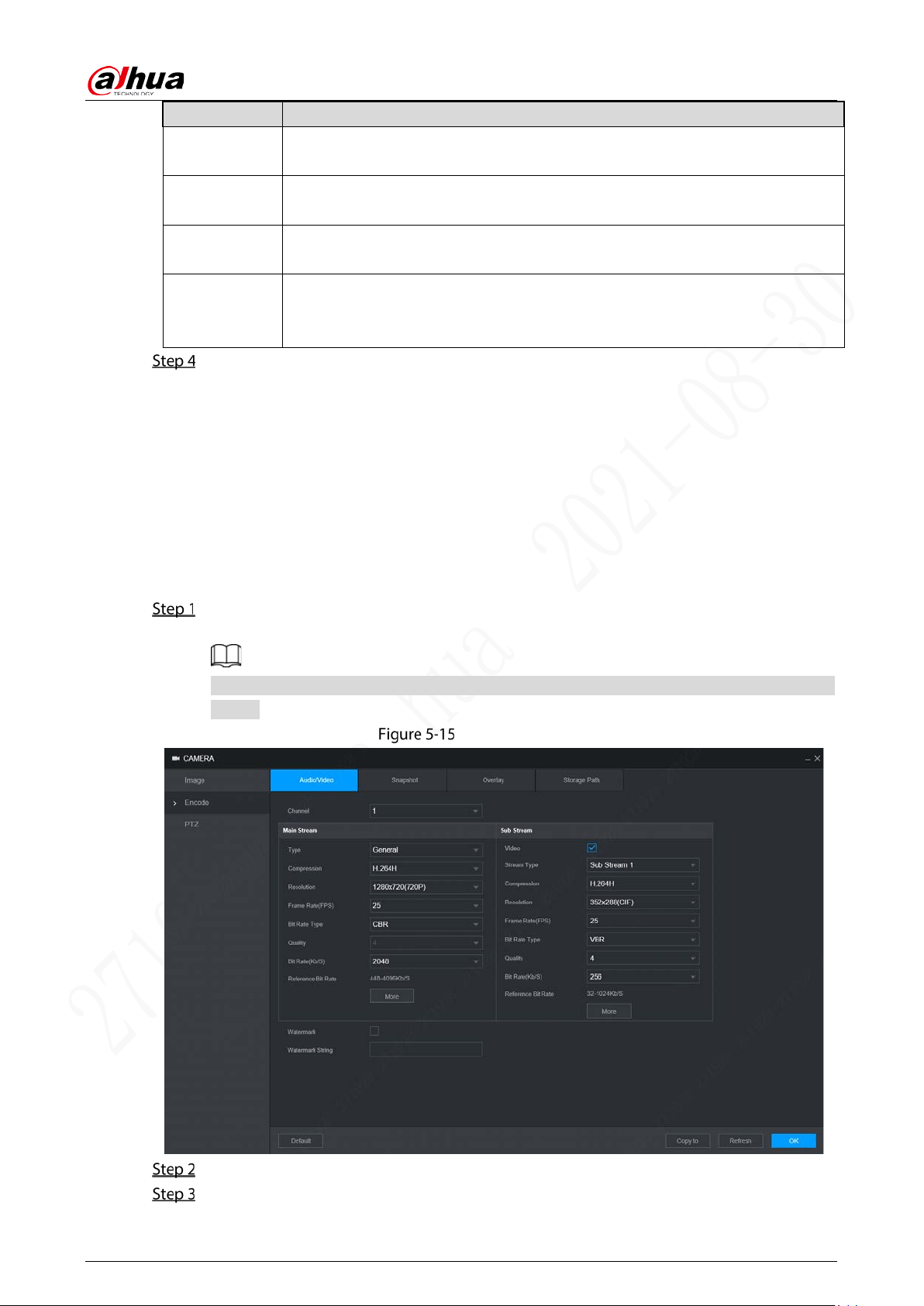
User’s Manual
55
Parameter Description
Hue
Adjusts the color hue. Adjust the hue according to the actual situation. The
bigger the value, the colder the color of the image will become.
Sharpness
Set the sharpness of picture edges. The bigger the value is, the more obvious the
image edge will become.
Hue
Adjusts the color darkness. Adjust the saturation according to the actual
situation. The bigger the value, the lighter the color of the image will become.
Color Mode
Select the color mode. There are 5 preinstall modes you can choose, or you can
set 4 custom modes for options. Preinstall modes includes Standard, Soft, Bright,
Vivid, Bank.
Click OK.
5.4.2 Encode Parameters
You can set Audio/Video, Snapshot, Overlay, and Storage Path.
5.4.2.1 Audio/Video
You can configure the encode settings for main stream and sub stream.
Select Setting > Camera > Encode > Audio/Video.
The Audio/Video interface is displayed, see Figure 5-15.
Encode parameters might be different depending on devices, and the actual product shall
prevail.
Audio/Video
Select a channel number.
Configure parameters. For details, see Table 5-8.
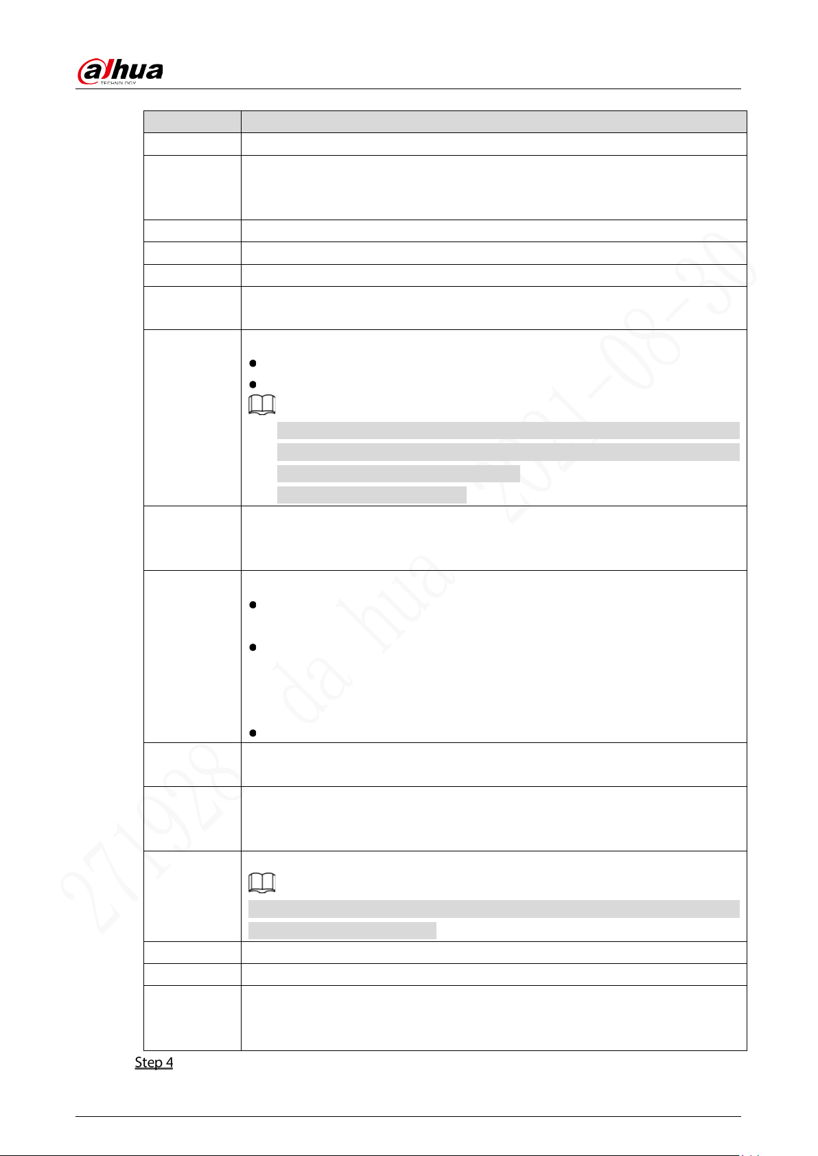
User’s Manual
56
Table 5-8 Encode setting parameters description
Parameter Description
Video Enable the sub stream.
Type
The record type of main stream is permanently fixed as general and cannot be
changed. General, motion detect and alarm use the general stream configurations
for recording.
Stream Type Sub stream types.
Compression Encode mode of video.
Resolution The higher the video resolution, the better the image quality.
Frame rate
(FPS)
Configure the frames per seconds for videos. The higher the value, the smoother
and more vivid the image.
Bit rate type
Select a control mode for bit rate of video.
CBR: The bit rate changes little and keeps close to the defined bit rate value.
VBR (Variable Bit Rate): The bit rate changes along with environment.
It is recommended to select CBR when there might be only small changes in
the monitoring environment, and select VBR
when there might be big
changes in the monitoring environment.
The main stream is fixed to VBR.
Quality
This parameter can be configured only when the Bit Rate Type is set as VBR.
Select the image quality level. There are six levels in total. The higher the value,
the better the image will become.
Bit rate(KB/S)
Configure the encode value for main stream and sub stream.
When CBR is selected, select the bit rate according to the reference bit rate,
and the bit rate changes along the configured value.
When VBR is selected, select the upper limit value of bit rate according to the
reference bit rate, and the bit rate changes along with the monitoring
environment. But the maximum bit rate value changes around the configured
value.
Select Customized, and you can configure bit rate value manually.
Reference Bit
Rate
The system recommends the optimal bit rate range according to the resolution
and frame rate settings.
Audio Enable
Click More to enable the audio.
If the corresponding check box is selected, the video recordings are audio and
video combined streams.
Compression
Select an audio encode format.
The parameters might be different depending on the model you purchased, and
the actual product shall prevail.
Audio Source Source of audio.
Watermark
Select the Watermark check box to verify whether the recorded video is falsified.
Watermark
String
Enter the strings for verifying watermark. The default string is DigitalCCTV. You
can configure at most 127 watermark characters which are composed of number,
letter, underline and dash.
Click OK.
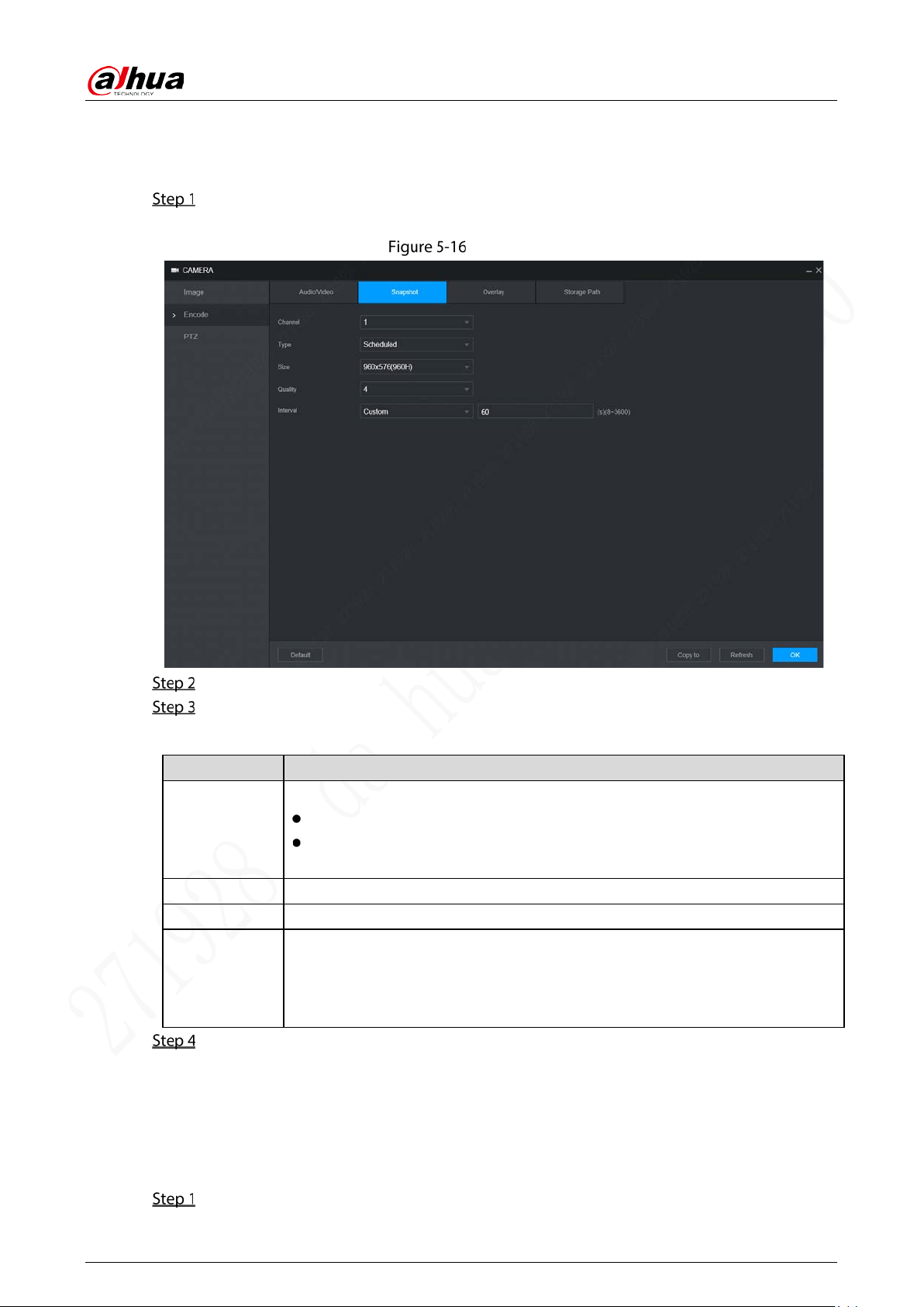
User’s Manual
57
5.4.2.2 Snapshot
You can configure the snapshot settings such as snapshot type, image size, quality, and interval.
Select Setting > Camera > Encode > Snapshot.
The Snapshot interface is displayed, see Figure 5-16.
Snapshot
Select Channel.
Configure parameters. For details, see Table 5-9.
Table 5-9 Snapshot stream parameters description
Parameter Description
Type
Includes scheduled and event.
Schedule: Take snapshots within the configured period.
Event: Take snapshots when alarms such as local alarm, video detection and
abnormality are triggered.
Size Select a resolution for the captured image.
Quality The image quality and there are six levels in total.
Interval
Interval of taking snapshots.
Select Custom to configure the snapshot interval for manually captured
snapshots. The maximum value you can set is 3600 seconds as an interval
between two snapshots.
Click OK.
5.4.2.3 Overlay
You can configure to display the information such as system time and channel name on each channel
window in the live view screen.
Select Setting > Camera > Encode > Overly.
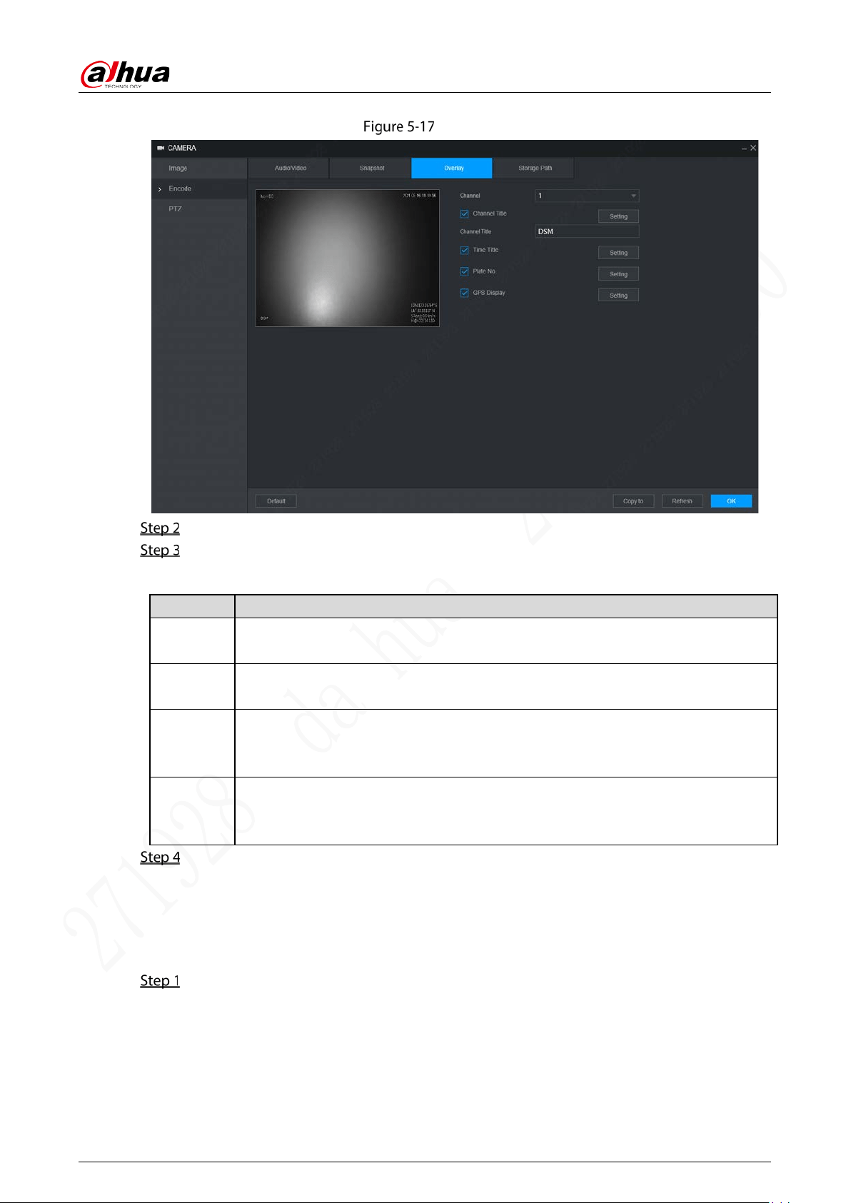
User’s Manual
58
The Overlay interface is displayed. See Figure 5-17.
Overlay
Select a Channel.
Configure parameters. For details, see Table 5-10.
Table 5-10 Video overlay settings parameters description
Parameter Description
Channel
Title
Select Channel Title, and the Setting button is displayed. Then click Setting on the
right of the Channel Title, enter the channel title, and drag it to a proper location.
Time Title
Select the Time Title check box, the Setting button is displayed. Then click Setting,
the time is displayed on the channel window, and then drag it to a proper location.
Plate No
Select the Plate No check box, the Setting button is displayed. Then click Setting,
the plate number is displayed on the channel window, and then drag it to a proper
location.
GPS
Display
Select the GPS Display check box, the Setting button is displayed. Then click
Setting, the GPS display frame is displayed on the channel window, and then drag it
to a proper location.
Click OK.
5.4.2.4 Storage Path
You can configure the storage path of captured snapshots and recorded videos.
Select Setting > Camera > Encode > Storage Path.
The Storage Path interface is displayed. See Figure 5-18.
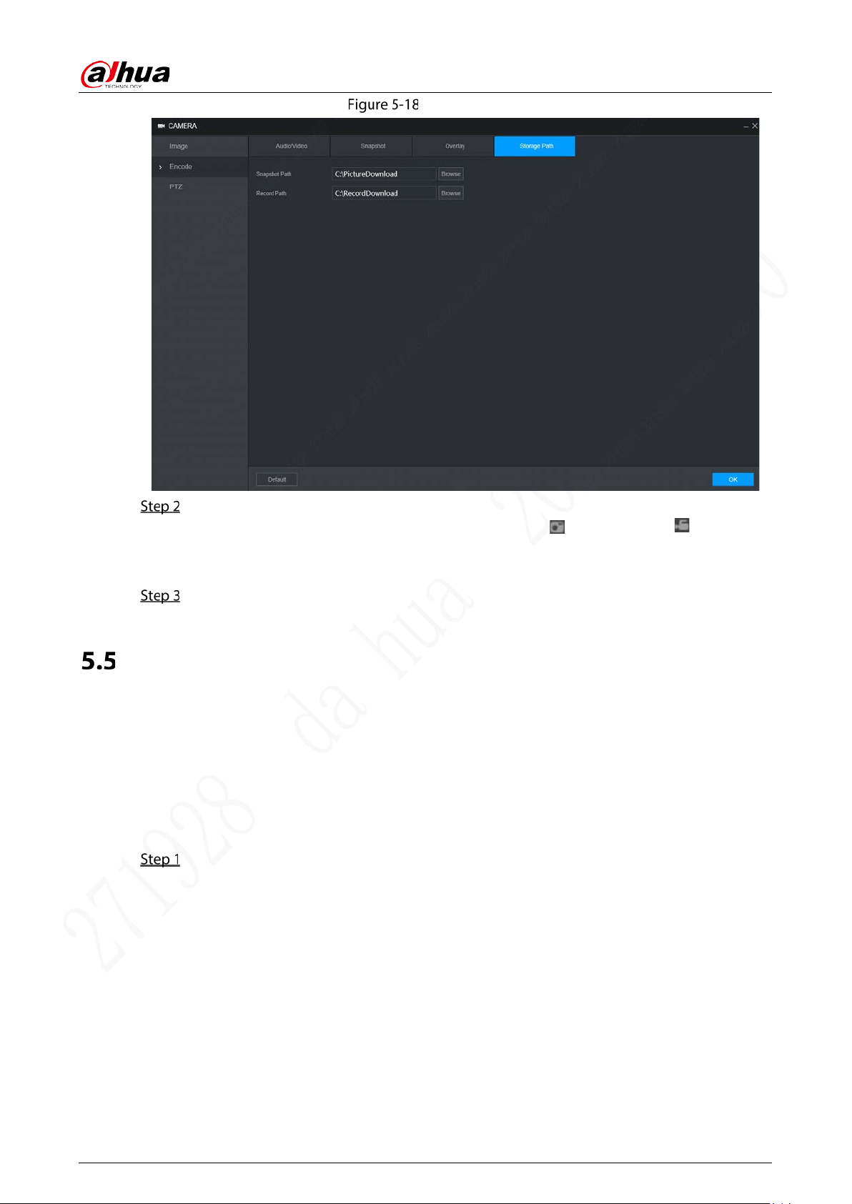
User’s Manual
59
Storage path
Click Browse to select the storage path for snapshots and recordings.
Images and recordings by using functions of snapshots and recordings on the Live
interface are saved in these two paths by default. Default paths: C:\PictureDownload and
C:\RecordDownload.
Click OK.
Configuring Network Parameters
You can set the network parameters of the device as needed, including ports, Wi-Fi parameters, 3G/4G
parameters, Email, auto register, P2P, and Operation platform.
5.5.1 Port
Set each port value of the device.
Select Setting > Network > Port.
The Port interface is displayed. See Figure 5-19.
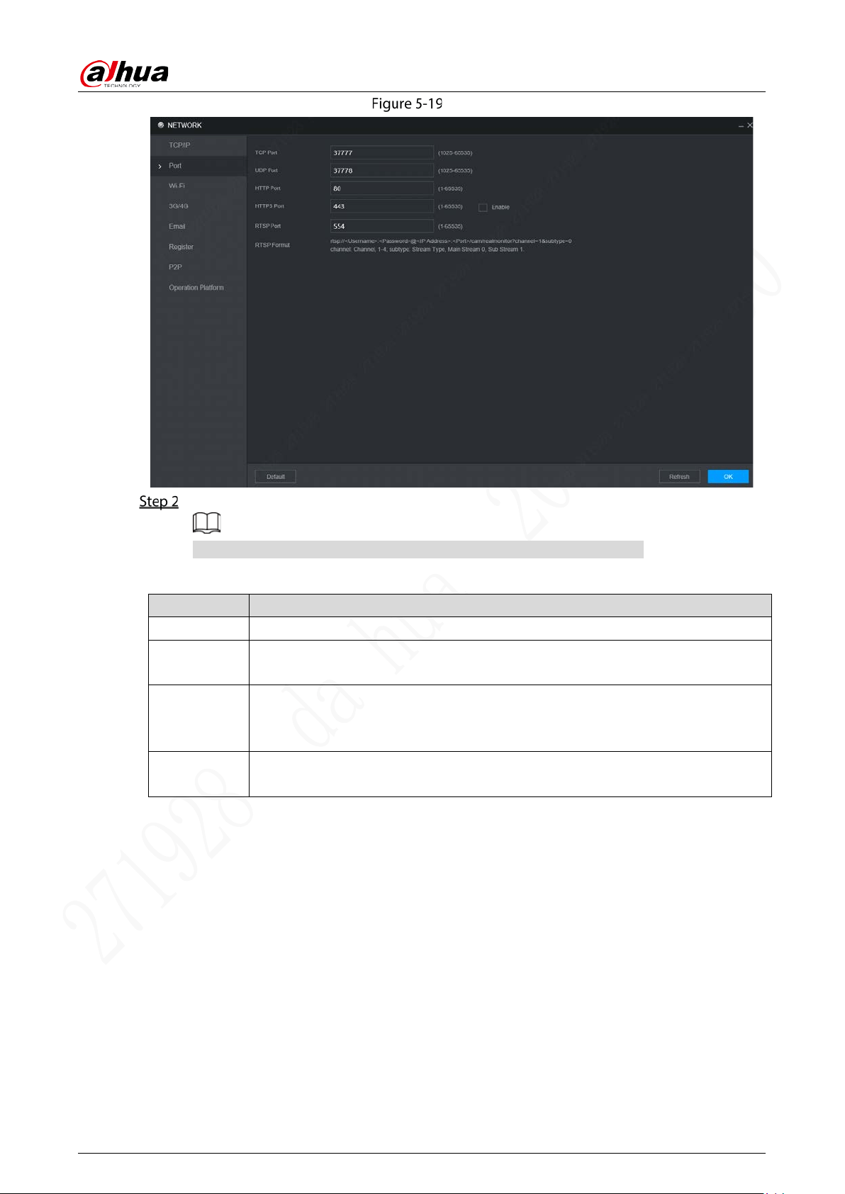
User’s Manual
60
Port
Configure the ports of the device. For details, see Table 5-11.
The revised settings take effect after device restart. Proceed with caution.
Table 5-11 Port parameters description
Parameter Description
TCP Port Transmission control protocol port. The value is 37777 by default.
UDP Port
User Datagram Protocol port.The default value setting is 37778. You can enter the
value according to your actual situation.
HTTP Port
Hyper Text Transfer Protocol port. The default setting is 80. You can enter the value
according to your actual situation, and in this case, please add the modified port
number after the address when logging the device on the browser.
HTTPS Port
Hyper Text Transfer Protocol over Secure Socket Layer port. Select the Enable
check box, and then enter the value as needed. The value is 443 by default.

User’s Manual
61
Parameter Description
RSTP Port
Real Time Streaming Protocol port. Keep the default value 554 if it is displayed. If
you play live view through Apple’s QuickTime or VLC, the following format is
available. This function is also available for Blackberry.
When the URL format requiring RTSP, you need to specify channel number and bit
stream type in the URL, and also user name and password if needed.
When playing live view with Blackberry smart phone, you need to turn off the
audio, and then set the code mode to H.264B and resolution to CIF.
URL format example:
rtsp://<User Name>:<Password>@<IP
Address>:<Port>/cam/realmonitor?channel=1&subtype=0
User name. For example: admin.
Password: For example: admin_123.
IP address: For example, 192.168.1.16.
Port: The default setting is 554. If the default setting is displayed, you do not
need to configure this parameter.
Channel: Numbers from 1. For example, if it is channel 2, then enter channel=2.
Subtype: stream type. The main stream is 0 (subtype=0); the sub stream is 1
(subtype=1).
For example, if you require the sub stream of channel 2 from a device, then the
URL shall be:
=1
If certification is not required, you do not need to specify the user name and
password: Use the following format:
rtsp:// <IP Address>:<Port>/cam/realmonitor?channel=1&subtype=0
Click OK.
5.5.2 Wireless Network
You can connect the device to a network through Wi-Fi. Make sure the device can communicate with
other devices in the group network. The device itself can also act as a hot spot to share flows with other
terminals.
If both 3G/4G and Wi-Fi are available, the device connects to Wi-Fi and disconnects from 3G/4G.
5.5.2.1 Wi-Fi
You can connect the device to a network through Wi-Fi. Then connect the PC to the same network. You
can log in to the WEB interface by PC to operate the device.
This function is only supported on the device with a Wi-Fi module. The actual situation shall prevail.
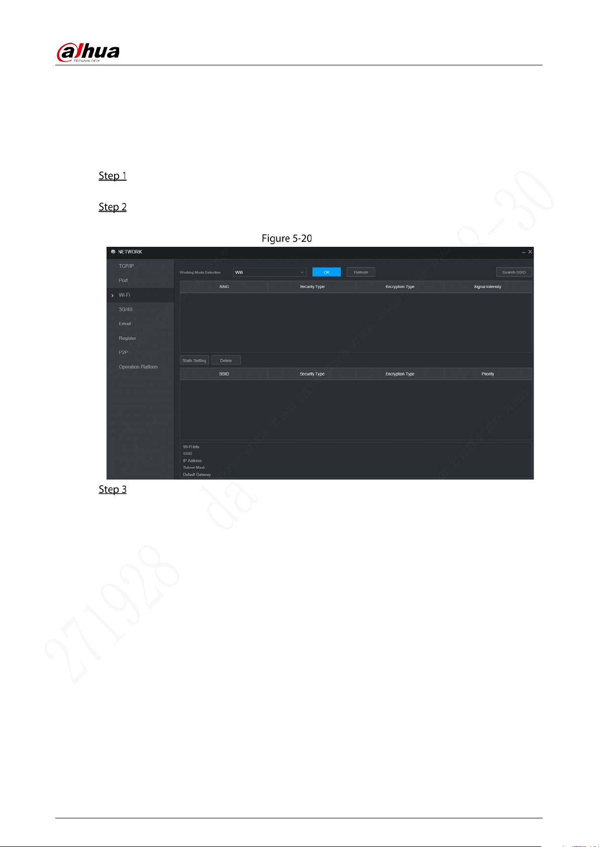
User’s Manual
62
Prerequisites
Make sure that the device is connected to a Wi-Fi module.
Procedure
Select Setting > Network > Wi-Fi.
The Wi-Fi interface is displayed.
Select Wi-Fi as the working mode.
The Wi-Fi interface is displayed, see Figure 5-20.
Wi-Fi
Connect to Wi-Fi.
Auto search
1. Click Search SSID.
The available Wi-Fi networks list including the information such as connection
mode, authorization mode, and signal intensity.
2. Double-click the Wi-Fi you need, enter the password and click OK.
Add Wi-Fi manually
1. Click Static Setting.
The Wi-Fi interface is displayed. See Figure 5-21.
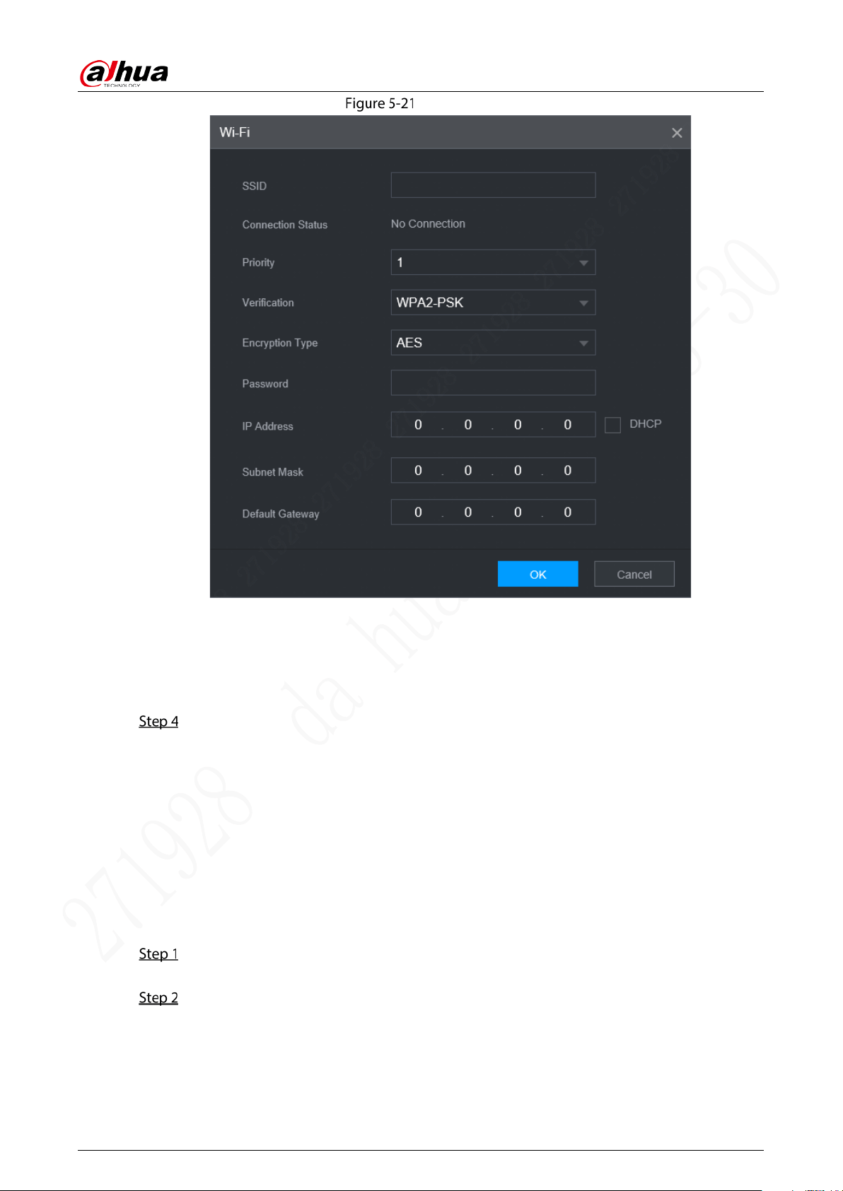
User’s Manual
63
Wi-Fi setting
2. Enter SSID and password, select priority level, verification type and authentication
type, set IP address, subnet mask, and default gateway.
If you select DHCP check box, after successful connection, the system
automatically obtains the IP address, subnet mask, and gateway.
3. Click OK.
Click OK.
Click Refresh to refresh the connection status.
After successful connection, you can view the current hot spot, IP address, subnet mask, and
gateway in Wi-Fi Info.
5.5.2.2 Ap
The device can work as a hotspot to share the network connection to other terminals. The terminals
connected to the hot spot can log in to the device through host IP address (192.168.0.108). After login,
you can view videos on the device.
Select Setting > Network > Wi-Fi.
The Wi-Fi interface is displayed.
Select Ap as the working mode.
The Ap interface is displayed. See Figure 5-22.
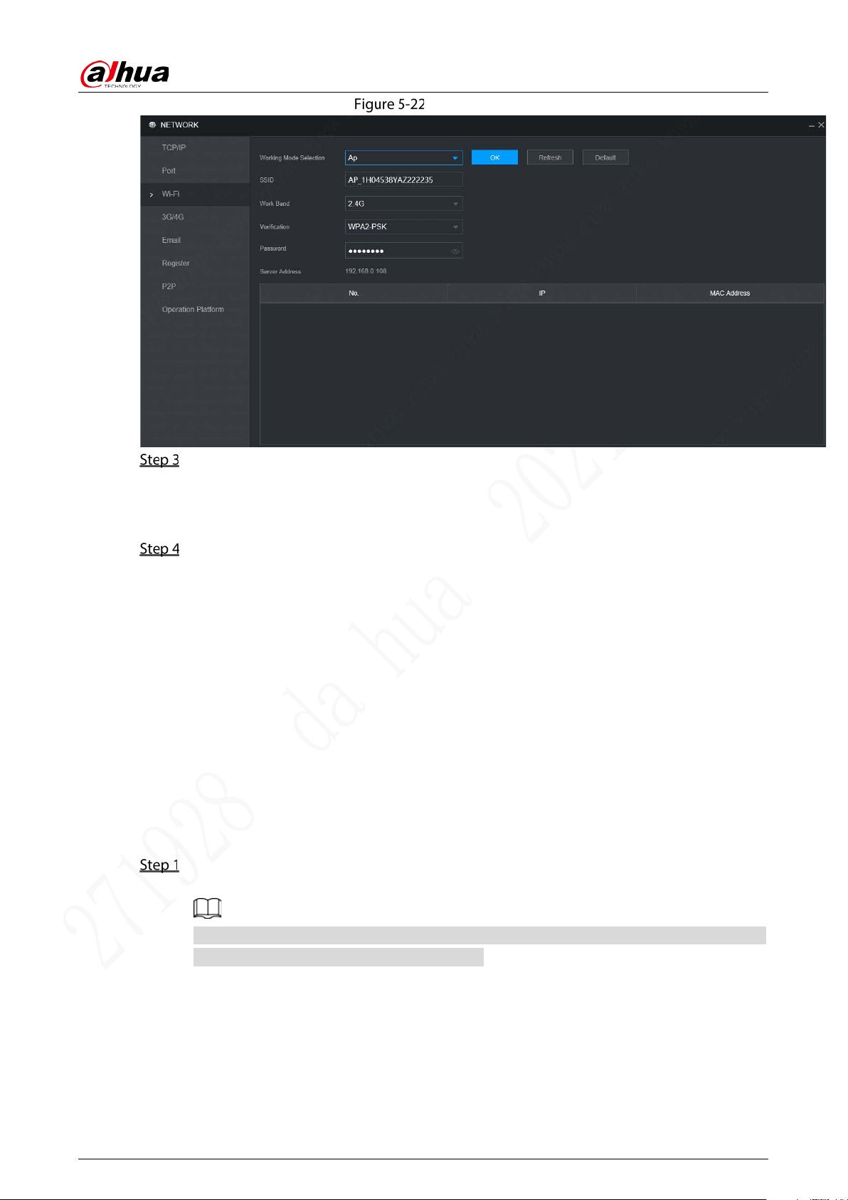
User’s Manual
64
Ap setting
Enter SSID information, select work band and verification, and then enter the password.
The work band can only be 2.4G.
Select the check box behind Password, and the password will be visible. The default
password is 12345678.
Click OK.
5.5.3 3G/4G
Prerequisites
Make sure the device is equipped with 3G/4G module and inserted with SIM card from the
Communication Operator.
The dial number, user name, and password have been obtained from the Communication
Operator.
Procedure
Select Setting > Network > 3G/4G.
The 3G/4G interface is displayed. See Figure 5-23.
After 3G/4G module is connected, the module information and wireless signal are displayed;
if not, click Search to search for wireless signal.
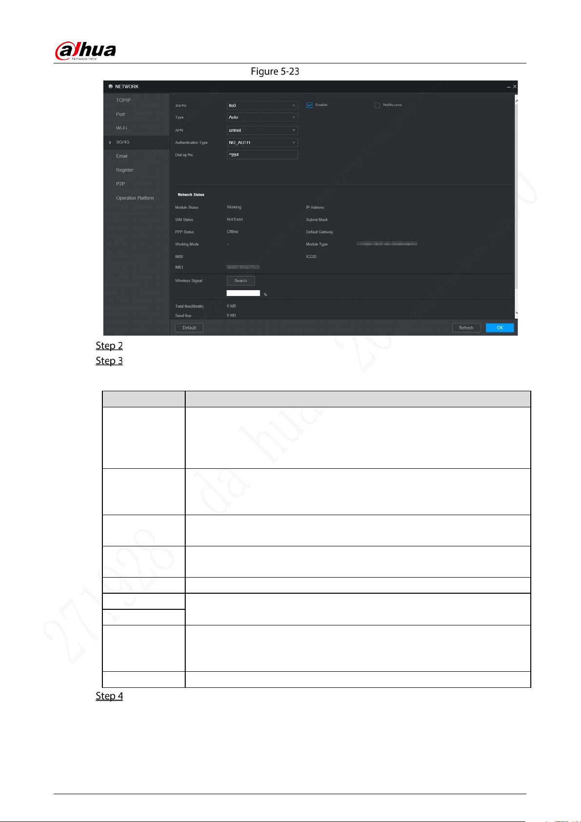
User’s Manual
65
3G/4G
Select 3G/4G and Enable to enable the network. This function is enabled by default.
Configure parameters. For details, see Table 5-12.
Table 5-12 3G/4G setting parameters description
Parameter Description
NetAccess
When the Device is accessed to private network, select the NetAccess check
box, enter APN name and select authentication mode. If PAP or CHAP is
selected for authentication mode, enter user name and password, then the
device is automatically accessed to private network.
Type
When enabled, the network type is displayed, which is used to distinguish
between the 3G/4G modules of different communication operators, such as
TD-LTE.
APN
Displays access point of Communication Operator.
To manually set up APN, select Customized.
Authentication
Type
Includes PAP, CHAP, and NO_AUTH protocols. The system automatically
recognizes and displays the enabled protocol.
Dial-up No Enter the dial number provided from the Communication Operator.
User Name
This parameter needs to be set up when AUTH is set to PAP or CHAP.
The system automatically recognizes the user name and password.
Password
Network Status
After successful dial-up, all relevant information is displayed without any setup
needed. Such information includes module status, SIM status, PPP status,
working mode, IMSI, IMEI, IP address, subnet mask, gateway, and module type.
Wireless Signal
Click Search to search for wireless signals.
Click OK.
After access is succeeded, the obtained IP address is displayed.
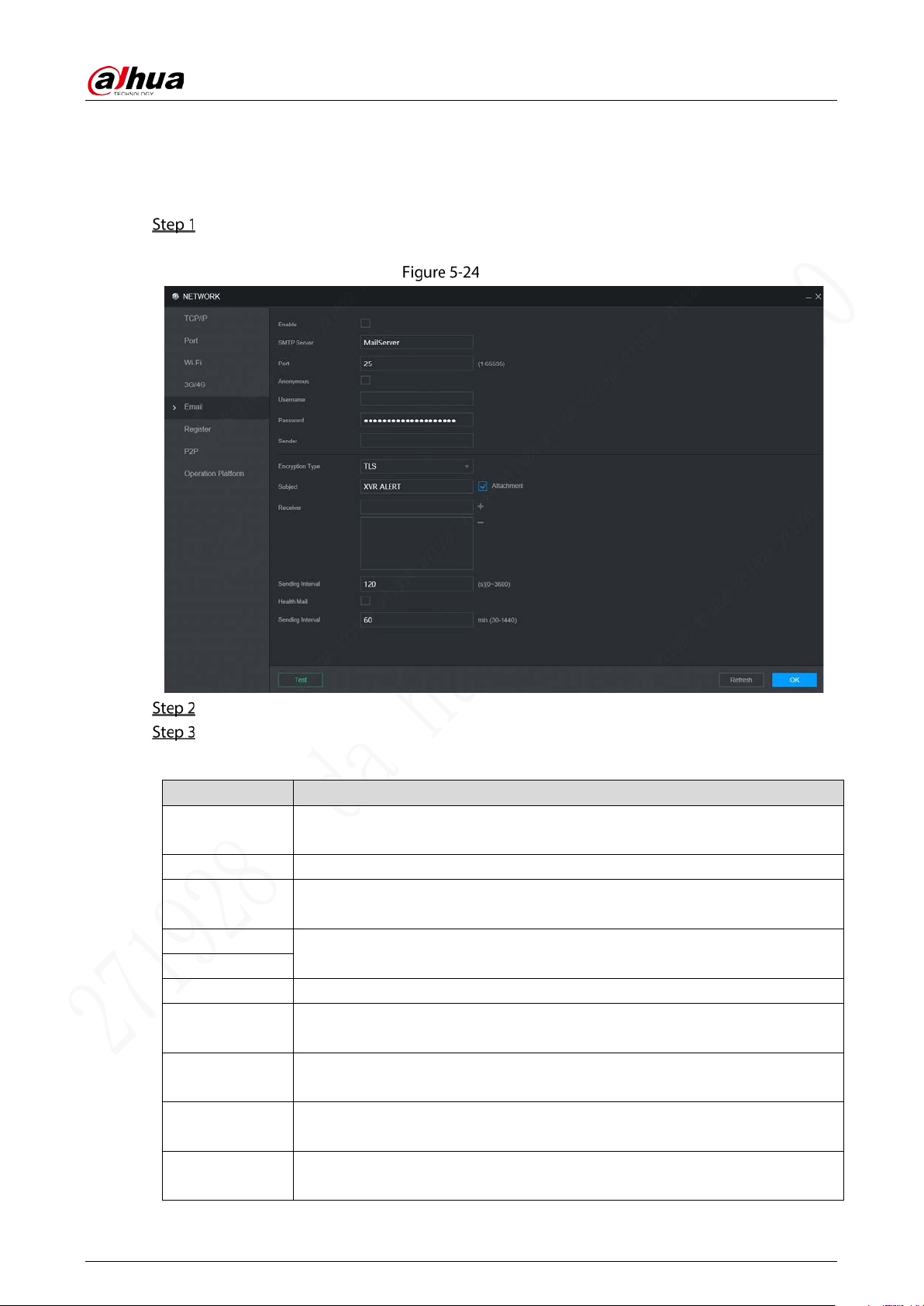
User’s Manual
66
5.5.4 Email
You can configure the email settings to enable the system to send the email as a notification when
there is an alarm event occurs, such as video detection and system events.
Select Setting > Network > Email.
The Email interface is displayed. See Figure 5-24.
Email
Select Enable to enable email function.
Configure parameters. For details, see Table 5-13.
Table 5-13 Email parameters description
Parameter Description
SMTP server
Configure the address of Simple Mail Transfer Protocol. For details, see Table 5-
14.
Port Enter the port value of SMTP server. For details, see Table 5-14.
Anonymous
If Anonymous is selected, the sender information is not displayed when
sending an email.
User Name
Enter the user name and password of SMTP server. For details, see Table 5-14.
Password
Sender Email address of sender.
Encryption Type
In the Encrypt list, select an encryption type from None, SSL, and TLS. For
details, see Table 5-14.
Subject
You can enter no more than 63 characters in Chinese, English, and Arabic
numerals.
Attachment
If Attachment is enabled, when an alarm takes place, the system can send
alarm linked snapshots.
Receiver
Receiver’s Email address. You can enter up to three email addresses separated
by colons.
User’s Manual
67
Parameter Description
Sending Interval
This is the interval that the system sends an email for the same type of alarm
event, which means, the system does not send an email upon any alarm event.
The interval ranges from 0 through 3600 seconds. 0 means that there is no
interval.
This setting helps to avoid the large amount of emails caused by frequent alarm
events.
Health Mail
The system can send a test email to check the connection.
Select the Health Mail check box, and then enter the interval. The system can
send a test email to check the connection after the specified interval.
The interval ranges from 30 minutes to 1440 minutes.
Test
Click Test to test if emails can be sent out and received as intended. If the
configuration is correct, the receiver’s email account will receive the test email.
Before testing email, click OK to save the email configuration.
For the configuration of major mailboxes, see Table 5-14.
Table 5-14 Common mailbox configuration parameters
Mailbox
type
SMTP server
Authentication
method
Port Description
QQ smtp.qq.com
SSL 465
Do not select None for encryption.
The mailbox must have applied
SMTP service.
The password must be an
“authorized password”
. Both the
QQ login password and email login
password are invalid.
Obtain the authorized password when
your mailbox is applying for SMTP
service.
TLS 587
163 smtp.163.com
SSL 465/994
The
mailbox must have applied
“SMTP” service.
The password must be an
“authorized password”. The email
login password is invalid.
Obtain the authorized password when
your mailbox is applying for SMTP
service.
TLS 25
NONE 25
Sina smtp.sina.com
SSL 465
The mailbox must have applied “SMTP”
service.
NONE 25
126 smtp.126.com NONE 25
The mailbox must have applied “SMTP”
service.
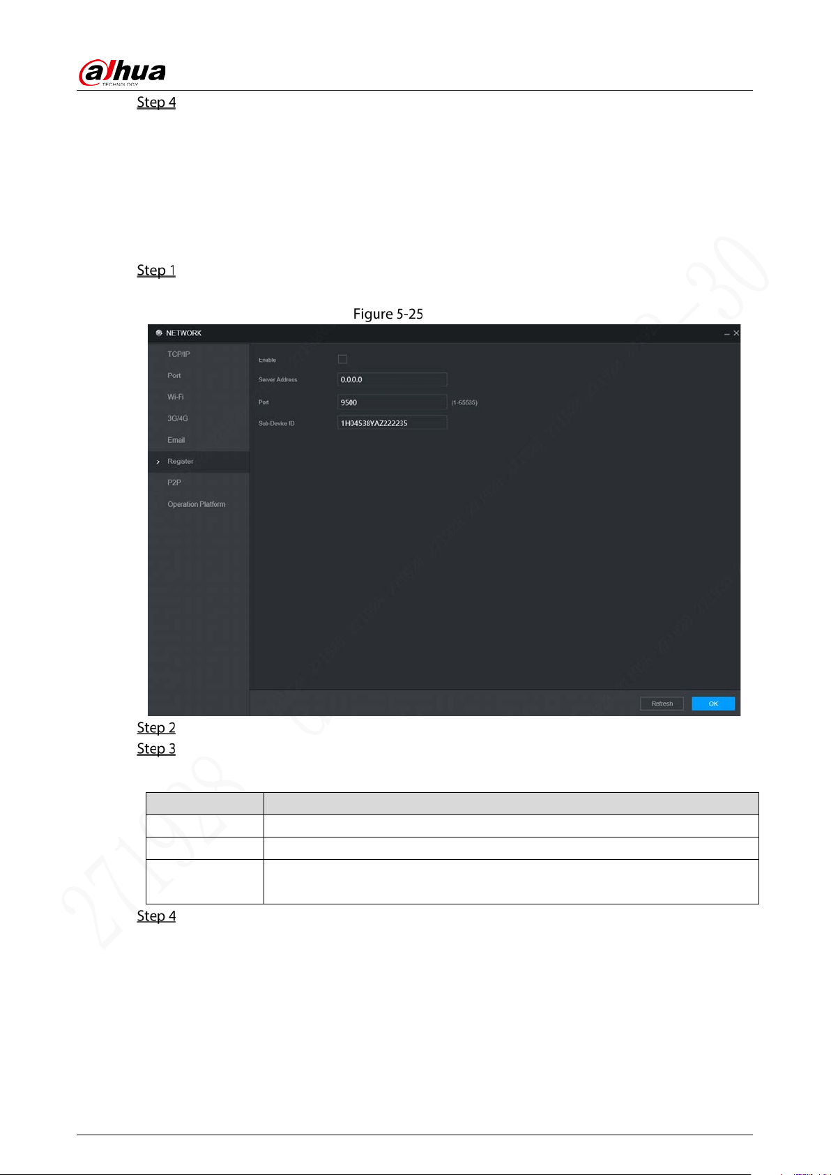
User’s Manual
68
Click OK.
5.5.5 Register
After successfully auto registered, when the device is connected into the Internet, it will report the
current location to the specified server to make it easier for the client software to access to the device,
and to view and monitor it.
Select Setting > Network > Register.
The Register interface is displayed. See Figure 5-25.
Register
Select the Enable check box. (Selected by default)
Configure parameters. For details, see Table 5-15.
Table 5-15 Register Parameters
Parameter Description
IP Address Enter the IP address or domain name of the server to register.
Port The port for auto-registration.
Sub-device ID
Unique ID for identifying the device. When different devices register to the
same server, the sub-device IDs should be different.
Click OK.
5.5.6 P2P
P2P is a private network penetration technology. With this technology, you do not need to apply for
dynamic domain name, set port mapping, or deploy transit server. You can add devices for
management by either of the following two ways.
Scan the QR code on the interface to download the app, and register an account.
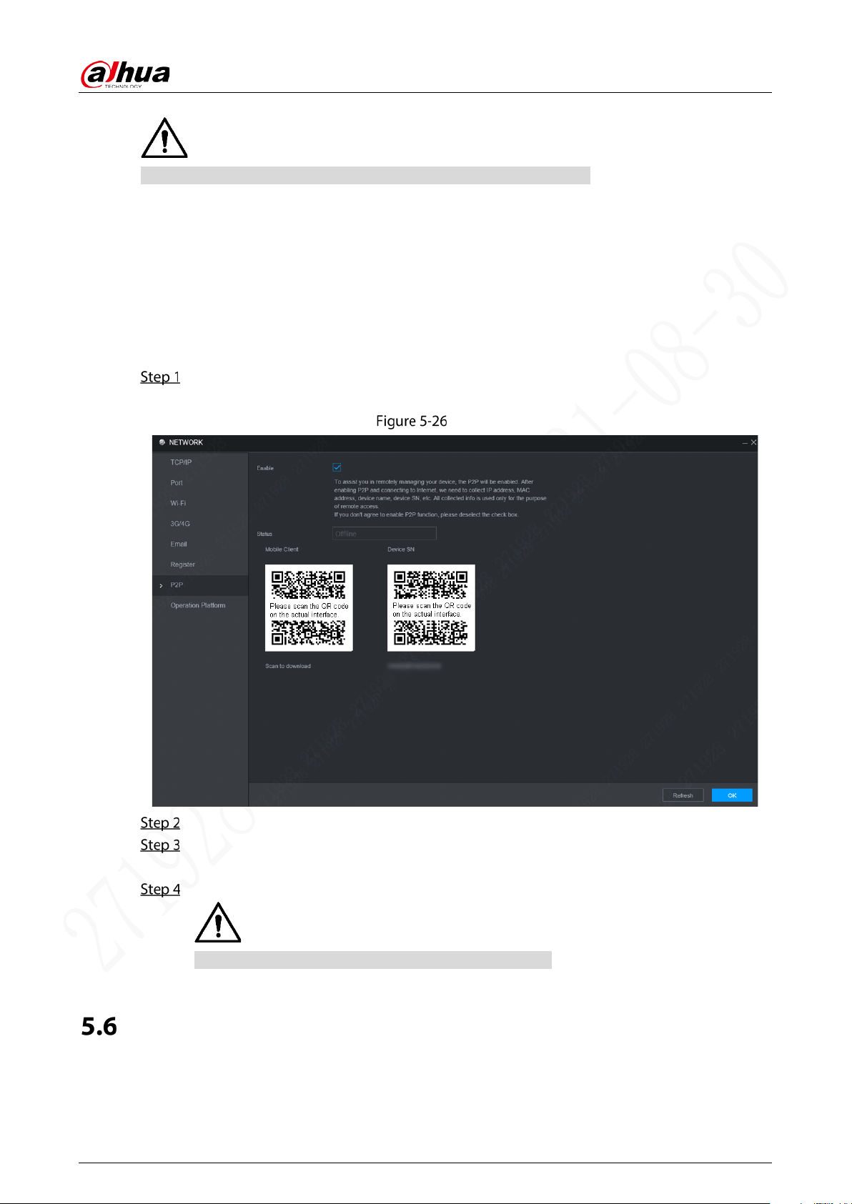
User’s Manual
69
Log in www.gotop2p.com platform to register, and then add devices by device serial number.
Before using P2P, make sure that the device is connected to the Internet.
Prerequisites
The device had been connected to the Internet.
App has been downloaded and installed on the mobile phone.
Procedure
Select Setting > Network > P2P.
The P2P interface is displayed, see Figure 5-26.
P2P
Select Enable to enable P2P.
Click OK.
The P2P registration is successful when the Status shows Online.
Use Mobile Client to scan the QR code under Device SN to add the device to Mobile Client.
Please scan the QR code on the actual interface of device.
Managing Storage Device
You can configure storage, basic information, manage HDD, and review HDD information.
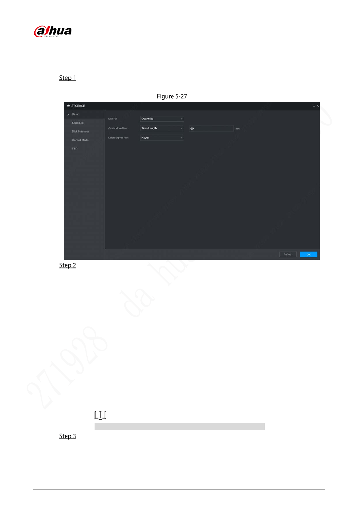
User’s Manual
70
5.6.1 Basic
On the Local interface, you can set up the strategy when the Disk is full and recording mode.
In the main menu, select Setting > Storage > Basic.
The Basic interface is displayed. See Figure 5-27.
Basic
Configure basic information.
Select the processing strategy of stopping recording and overwriting earlier recordings
when TF Card is full.
◇ Stop: The system stops recording when the disk is full.
◇ Overwrite: The system overwrites the oldest files and keeps recording when the
disk is full.
Set up the time length or file size for video packaging.
Select the required packaging manner from the Create Video Files drop-down list.
Including Time Length and File Size.
◇ Set the length of time for each video file. The default value is 60 minutes, and the
range is 1 minute –120 minutes.
◇ Set the size of file for each video file. The default value is 1024M, and the range is
128M –2048M.
Set the strategy of deleting old files automatically.
You can enable this function to delete recorded videos or images saved in TF card or FTP
server regularly according to the time gap you have set.
After setting file auto deletion, deleted files cannot be recovered.
Click OK.
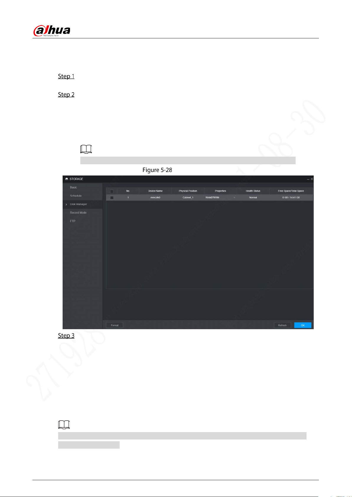
User’s Manual
71
5.6.2 Disk Manager
Set the read and write properties of the TF card and view the capacity information of the HDD.
Select Setting > Storage > Disk Manager.
The Disk Manager interface is displayed. See Figure 5-28.
Set the read and write properties of the TF card. You can set the TF card as the Read/Write disk,
Read-Only disk or Redundancy disk under the Properties column.
Read/Write: You can read data from TF card and save data in TF card.
Read-Only: You can only read data from TF card if set to read-only disk.
Redundancy: If the device is connected to two or more TF cards, one of the TF cards can
be set as the redundancy one for recording backup.
Select TF card and click Format to clear all data in the TF card. Proceed with caution.
Disk Manager
Click OK.
5.6.3 FTP
Configure FTP server, and then you can save videos and snapshots to the FTP server.
Prerequisites
You have deployed a FTP server, and created a user with the read & write permission.
The created FTP user should have write permission; otherwise the upload of videos, audios, and
snapshots will be failed.
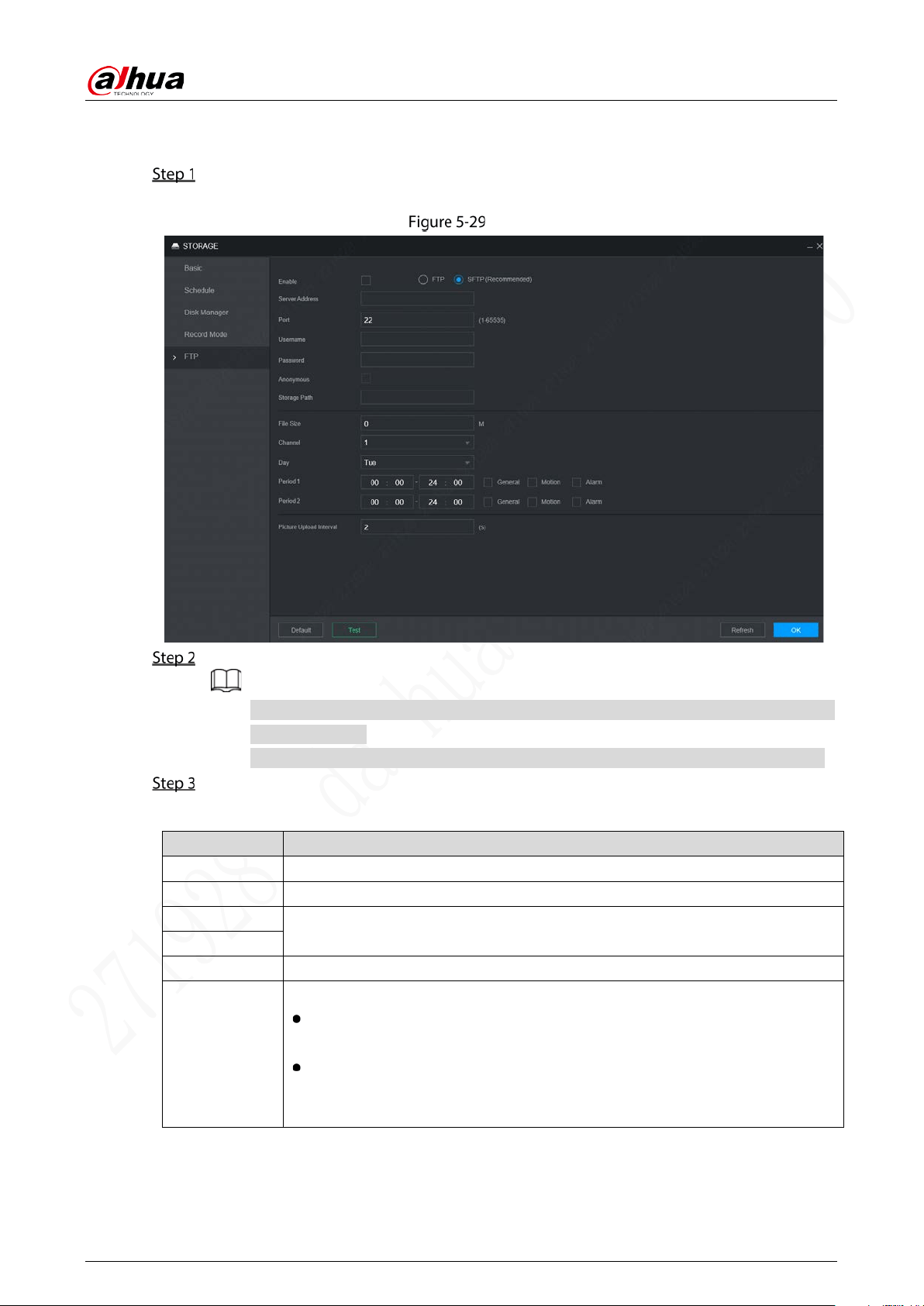
User’s Manual
72
Procedure
Select Setting > Storage > FTP.
The FTP interface is displayed, see Figure 5-29.
FTP
Select Enable to enable FTP upload and select FTP type.
You select FTP or SFPT from the drop-down list. SFTP is recommended to enhance
network security.
When FTP is selected, the system gives a risk prompt. Select OK or Cancel as needed.
Configure parameters. For details, see Table 5-16.
Table 5-16 FTP parameter description
Parameter Description
Server Address The IP address of the host PC that is installed with the FTP/SFTP server.
Port By default, SFTP port is 22 and FTP port is 21.
User Name
The user name and password used to access the server.
Password
Anonymous
Select Anonymous if you want to log in to the server anonymously.
Storage Path
Create folder on FTP server.
If you do not enter the name of remote directory, the system automatically
creates the folders according to the IP, time, and channel.
If you enter a name for the remote directory, the system creates a folder with
the entered name under the FTP/SFTP root directory first, and then
automatically creates folders based on IP, time, and channel.

User’s Manual
73
Parameter Description
File Size
Enter the size of the uploaded recorded video.
If the entered size is less than the recorded video size, only a section of the
recorded video can be uploaded.
If the entered size is more than the recorded video size, the whole recorded
video can be uploaded.
If the entered size is 0, the whole recorded video will be uploaded.
Choose
channel
Select the channel that you want to apply the FTP settings.
Weekday
Select the week day and set the time period that you want to upload the
recorded files. You can set two periods for each week.
Select the record type (Alarm, MD, and General) that you want to upload. After
selecting the corresponding recording type next to the corresponding period,
the selected recording type will be uploaded during the configured period.
Period
Picture Upload
Interval
When the Snapshot Type is Schedule, the upload method should be
determined based on the image upload interval and snapshot interval.
If this interval is longer than snapshot interval, the system uploads the
most recent snapshot. For example, if the interval is 5 seconds and
snapshot interval is 2 seconds, the system sends an upload command
to upload the next snapshot every 5 seconds.
If this interval is shorter than snapshot interval, the system uploads the
snapshot per the snapshot interval. For example, if the interval is 5
seconds and snapshot interval is 10 seconds, the system uploads the
snapshot every 10 seconds.
When the Snapshot Type is Event, the system uploads the snapshot as per
the snapshot interval.
You can change the Interval and Type. For details, see “5.4.2.2 Snapshot”.
Click Test to test if the FTP/SFTP server is successfully configured.
The system pops up a message to indicate success or failure.
If failed, please check the network connection or configurations.
Click OK.
Configuring System
You can configure system information, including serial port, security, and vehicle information.
5.7.1 Configuring Serial Port Parameters
You can configure the RS-232 serial port parameters such as baud rate, data bit, stop bit, and parity.
Select Setting > System > Serial Port.
The Serial Port interface is displayed. See Figure 5-30.
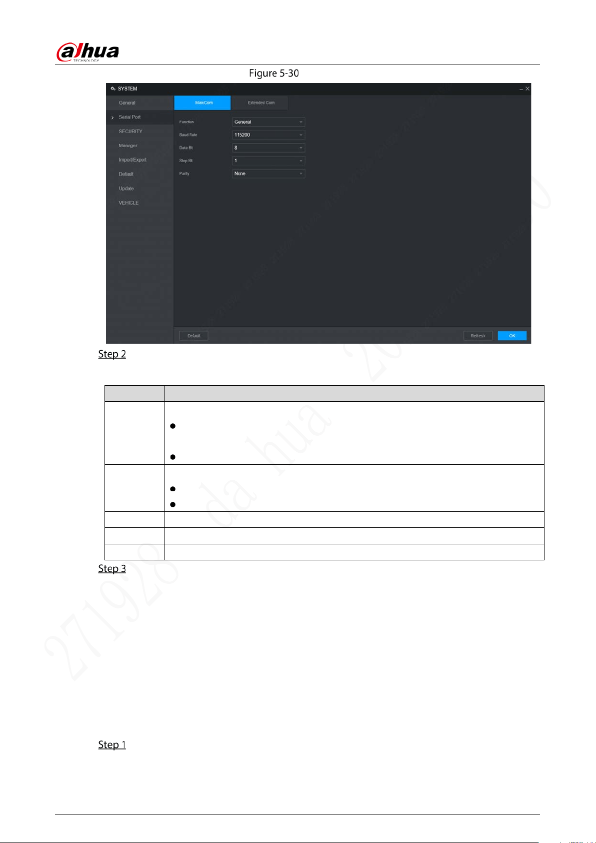
User’s Manual
74
Serial Port
Configure parameters. For details, see Table 5-17.
Table 5-17 Serial port setting parameters description
Parameter Description
Function
Select the corresponding protocol.
Console: Upgrades programs and debug by suing the serial interface and mini
terminal software.
GPS:Used to transmit real-time GPS data.
Baudrate
The times of signal changes on the transmission line in time unit.
The default baud rate is 115200 for a console.
The default baud rate is 9600 for a transparent serial port.
Data Bit
Select a data bit. The options include 5,6, 7, and 8.
Stop Bit
Select a stop bit. The options includes 1, 1.5, and 2.
Test
Select a parity mode from None, Odd, Even, Mark, and Null. The default is None.
Click OK.
5.7.2 Managing Security
It is to set security strategy to guarantee device network and data safety. It includes setting host IP
access right and enabling system service, etc.
5.7.2.1 System Service
The corresponding service can only be used after the system service is turned on.
Select Setting > System > Security > System Service.
The System Service interface is displayed. See Figure 5-31.
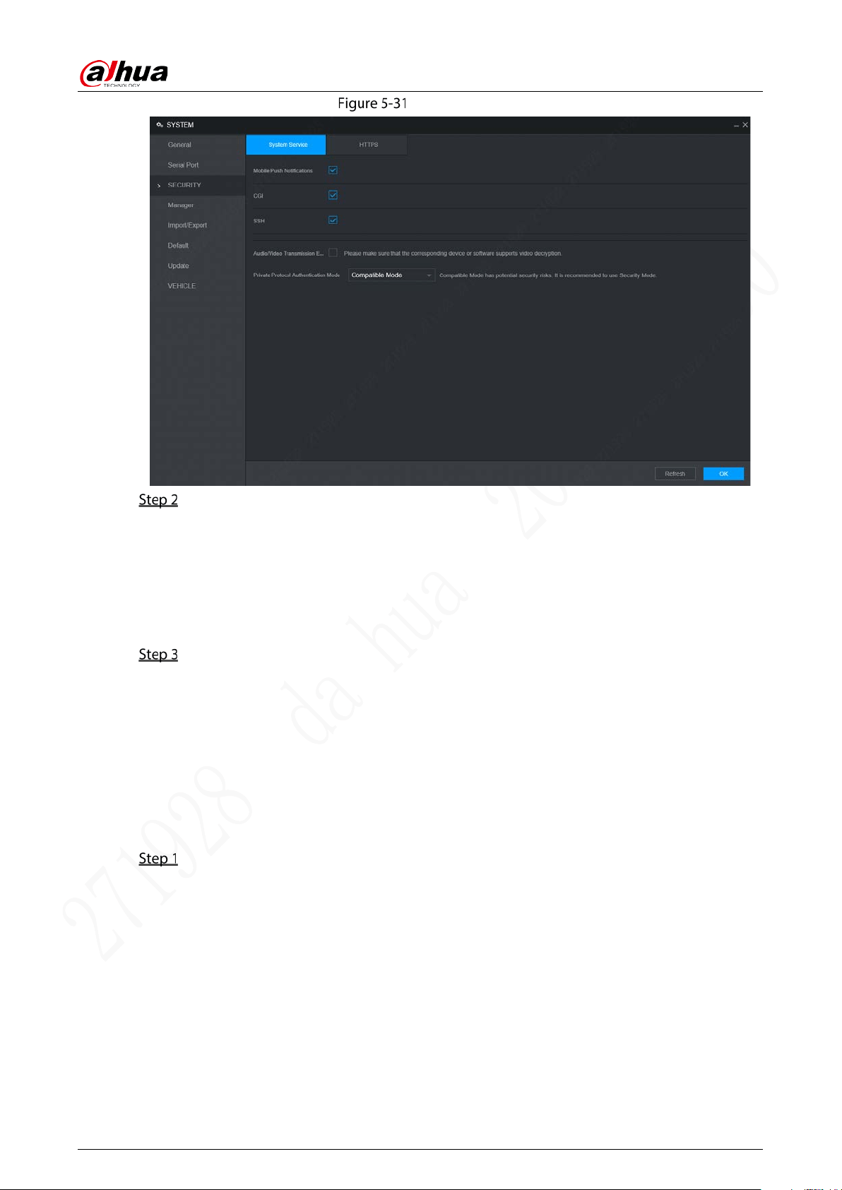
User’s Manual
75
System service
Select whether to enable mobile phone push, CGI, SSH, or audio/video transmission
encryption as needed.
App can receive alarm push only when the mobile phone push is enabled and the app
has subscribed alarm.
After enabling CGI, a third-party platform can connect to this device via the CGI protocol.
When audio/video transmission encryption is enabled, audio/video transmission will be
encrypted. Related devices or software shall support video decryption.
Click OK.
5.7.3 Configuring Vehicle Info
You can set the vehicle speed ratio and position report.
5.7.3.1 Configuring Speed
Select Setting > System > Vehicle > Speed.
The Speed interface is displayed. See Figure 5-32.

User’s Manual
76
Speed
Configure parameters. For details, see Table 5-18.
Table 5-18 Speed parameters description
Parameter Description
Speed Ratio The parameter for converting speed.
Mileage Cumulation Select the vehicle mileage cumulation mode.
Mileage Displays the total mileage.
Start Mileage Enter the initial mileage of the vehicle.
Speed source
Select where the speed is obtained, including Pulse, Position Info, and
Pulse&Position Info.
Pulse: Get the speed information from vehicle pulse system.
Position Info: Get the speed information from positioning system.
Pulse&Position Info: Gets the speed information from both the pulse
system and positioning system. Information from the pulse system is
used first.
Click OK.
5.7.3.2 Configuring Position Report
You can configure the position report strategy to be device auto report or report per platform schedule.
Select Setting > System > Vehicle > Position Report.
The Position Report interface is displayed. See Figure 5-33.
Configure the report strategy.
Device auto report.
1. In the Report Strategy list, select Device Auto.
The Device Auto setting interface is displayed. See Figure 5-33.
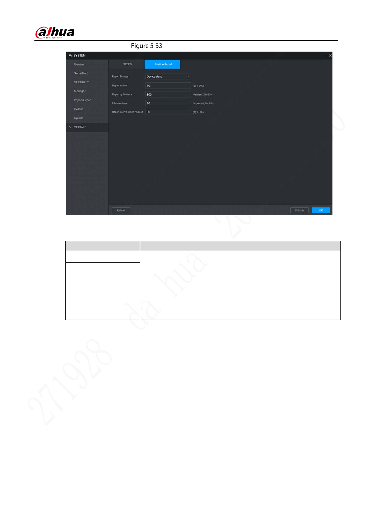
User’s Manual
77
Position report (device auto)
2. Configure parameters. For details, see Table 5-19.
Table 5-19 Device auto report parameters description
Parameter Description
Report Interval
When the vehicle ACC status is on, the system report the position to
platform according to the configured report interval, report distance,
and inflexion angle.
The system reports vehicle position to platform only if one of
conditions is satisfied.
Report by Distance
Inflexion Angle
Report Interval When
ACC off
When the vehicle ACC status is off, the system report the position to
platform according to the configured report interval.
Platform schedule.
In the Report Strategy list, select Platform Schedule. The Platform Schedule setting
interface is displayed. See Figure 5-34.
The platform obtains the device position by the configured schedule. The schedule is
configured at the platform. See the user's manual for the platform.
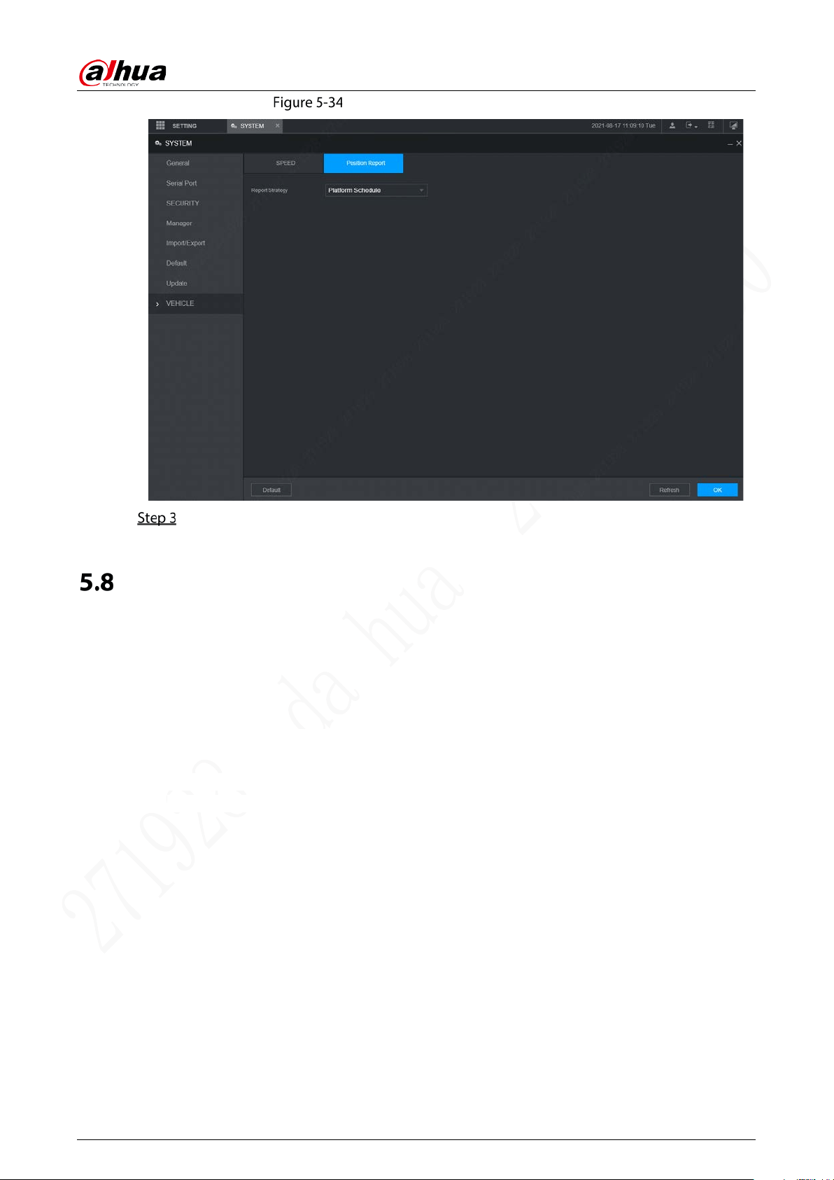
User’s Manual
78
Position report (platform schedule)
Click OK.
Managing User Account
You can add, modify and delete user accounts and groups, and configure security questions for admin
account.
The Default User and Authority
The default user account is admin.
The admin account is defined as the highly privileged user by default.
To manage user accounts easily, when defining the user account authority, it is recommended to
give lower authority to common user accounts than advanced user account.
About User and User Group
You can manage the account by user and user group, and the name cannot be repeated.
You can set maximum 64 users and 20 groups.
The default group name by “User” and “Admin” cannot be deleted.
Select the authorities to the user of a group. However, the authorities of the admin account
cannot be specified at your will.
Every user must belong to only one group. When selecting a group for a user, permissions of the
user can only be a subset of group permissions and cannot exceed permission attributes of the
group.
Both the user name and group name support 1–31 characters and can only consist of letter,
number, underline (_), and hyphen (-).
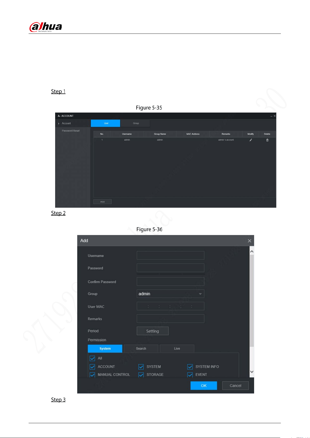
User’s Manual
79
5.8.1 Managing User
You can add, delete, or modify user, and set the authorities for the user of a group.
Adding a user
Select Setting > Account > Account > User.
The User interface is displayed. See Figure 5-35.
User
Click Add.
The Add interface is displayed. See Figure 5-36.
Add
Configure parameters. For details, see Table 5-20.
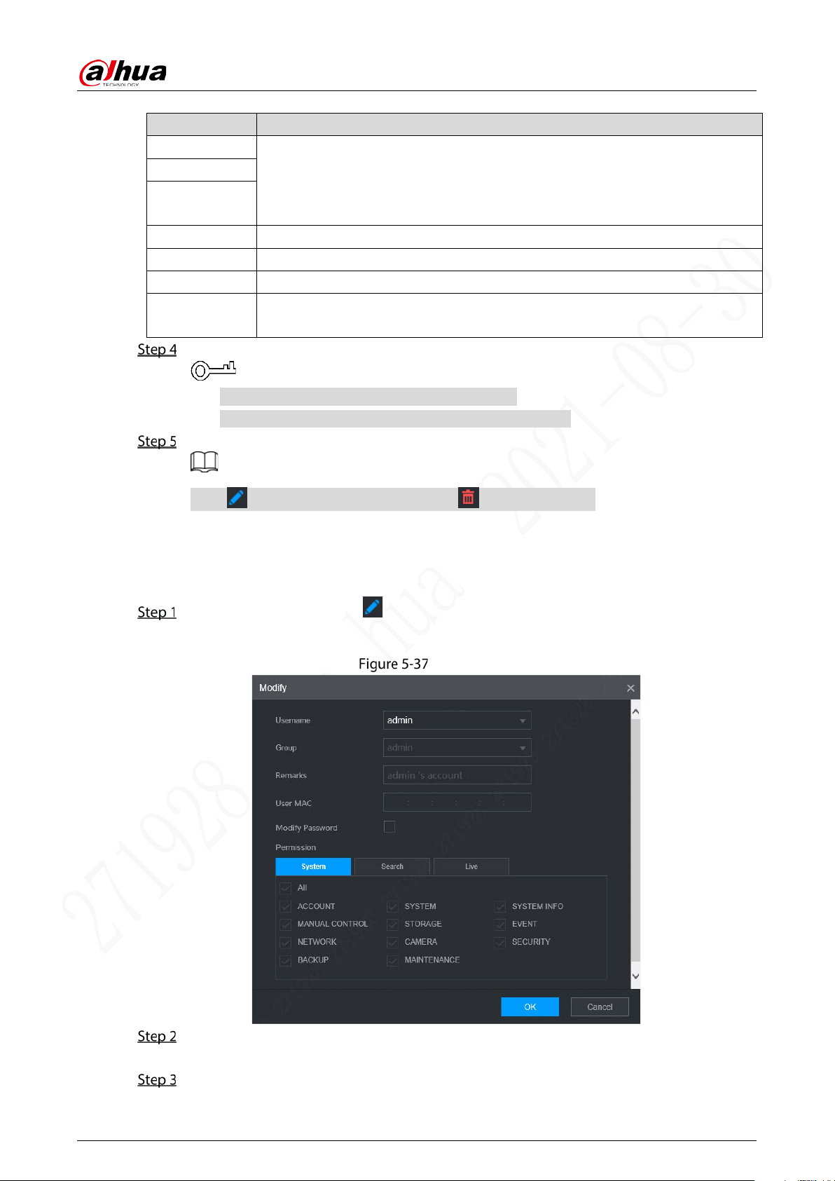
User’s Manual
80
Table 5-20 Parameters description for adding user
Parameter Description
User Name
Enter the user name and password, and confirm the password.
Password
Confirm
Password
Group Select the group that the users belong to.
User MAC Enter user MAC address that is allowed to login the device.
Remarks Enter a description of the user.
Period
Click Setting to set a valid period. The user is only allowed to log in to the device
in the set period.
Click System, Search, or Live to set up user permissions.
Select All to select all authorities in the category.
The authorities of the admin account cannot be changed.
Click OK.
Click to modify user information; click to delete the user.
Changing Password
On the User interface, click .
The Modify interface is displayed. See Figure 5-37.
Modify
Select the Modify Password check box, and then enter old password, new password, and
confirm password in the corresponding box.
Select the authority, including system, search, and live authorities.
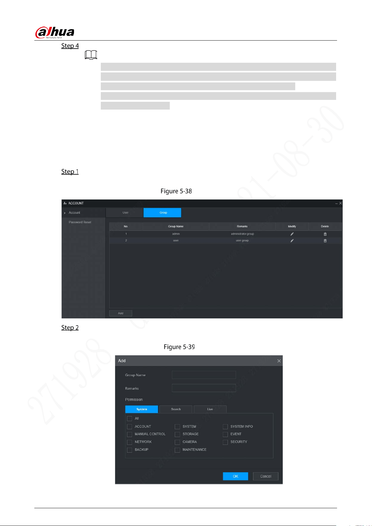
User’s Manual
81
Click OK.
The new password can be set from 8 characters through 32 characters and contains at
least two types from number, letter and special characters (excluding ' " 、; : &). Please
enter a strong password according to the password strength indication.
A user authorized to manage user accounts can modify its own password and the
passwords of other users.
5.8.2 Managing Group
You can perform the operations to manage the group account, such as adding a group, deleting a
group, and modifying a group.
Select Setting > Account > Account > Group.
The Group interface is displayed, see Figure 5-38.
Group
Click Add.
The Add interface is displayed. See Figure 5-39.
Add
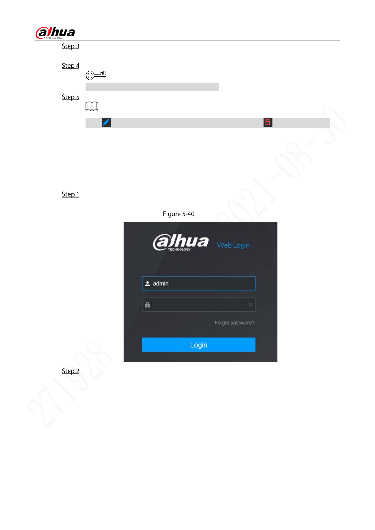
User’s Manual
82
Set group name and remarks.
A group name consists of letters, numbers, and special characters (including "_", "@", ".").
Select the authority, including system, search, and live authorities.
Select All to select all authorities in the category.
Click OK.
Click to modify the corresponding group information; click to delete the group.
5.8.3 Resetting Password
You can reset the password through the reserved phone number when you forget the login password
of admin.
Open a browser and login the WEB interface of device.
The Login interface is displayed. See Figure 5-40.
Login
Click Forgot password?
The Password Reset interface is displayed. See Figure 5-41
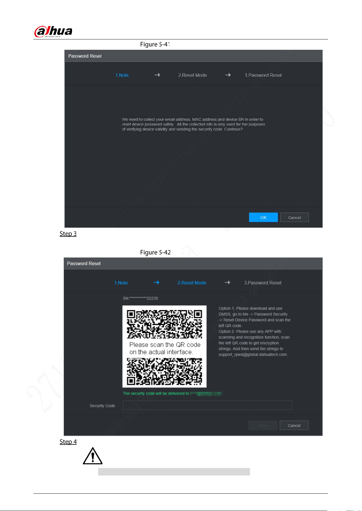
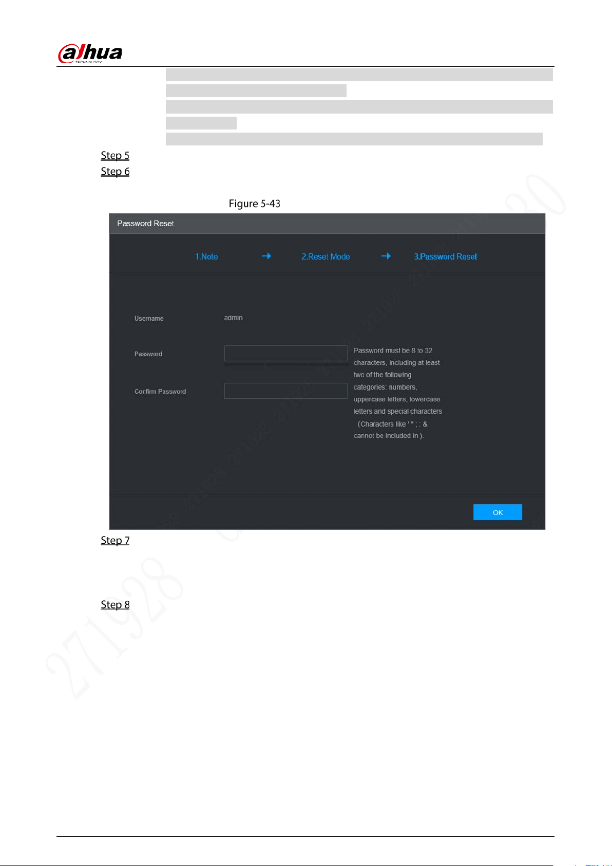
User’s Manual
84
At most two security codes will be generated by scanning the same QR code. To get
more security code, refresh the QR code.
Please use the security code within 24 hours after you receive it. Otherwise, it will
become invalid.
Wrong security code entered for up to five times will cause account locked for 5 min.
In the Security Code box, enter the security code received in your provided mailbox.
Click Next.
The new password setting interface is displayed. See Figure 5-43.
New password setting
Reset and confirm the password.
The new password can be set from 8 through 32 non-empty characters and contains at least
two types from number, letter and special characters (excluding “'”, “"”, “;”, “:” and “&”). Please
enter a strong password according to the password strength indication.
Click OK.
The system prompts successful operation and restarts. You can use the new password to log
in to the device.
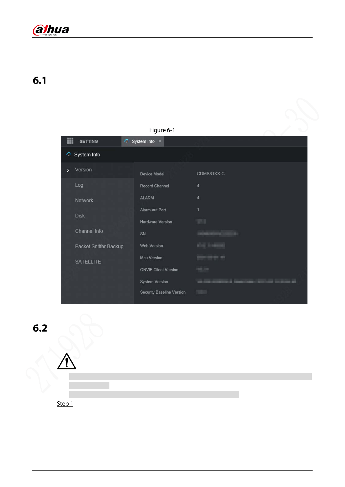
User’s Manual
85
6 Update
System Version
You can view the device hardware characteristics, version such information.
Select Setting > System Info > Version.
The Version interface is displayed. See Figure 6-1.
Version
Update
Import the update file in the format of .bin to update the system.
Do not disconnect the power or network, or restart or shut down the device during update
cannot be used.
Incorrect update programs may result in the device unable to work.
Select Setting > System > Update.
The Update interface is displayed. See Figure 6-2.
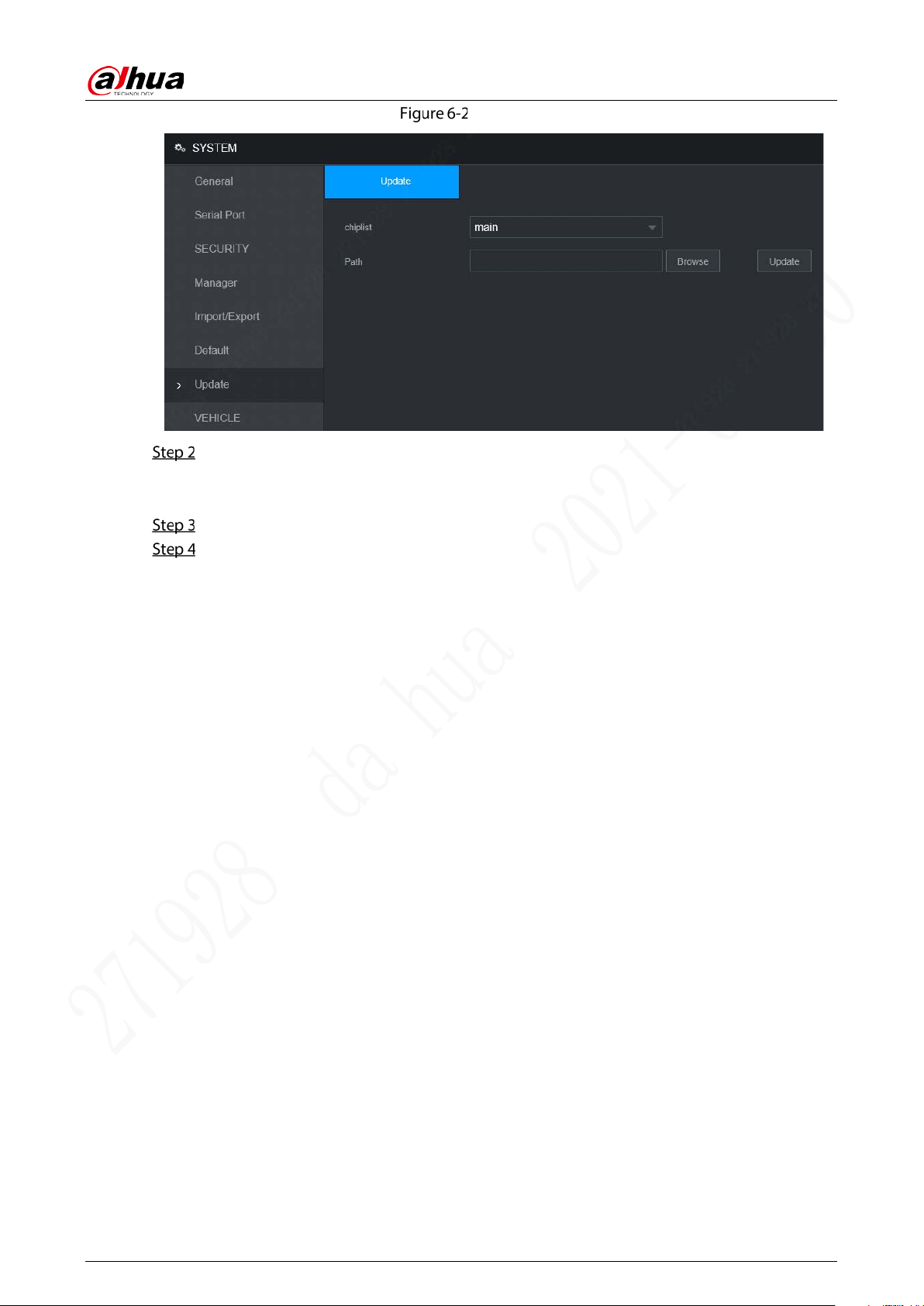
User’s Manual
86
Update
Select the chip list that suits your actual needs.
To update system programs, select Main for the chip list.
To update the MCU firmware programs, select MCU for the chip list.
Click Browse and select the update file you want to use.
Click Update.
The system starts updating. You should login to the WEB interface again after updating.
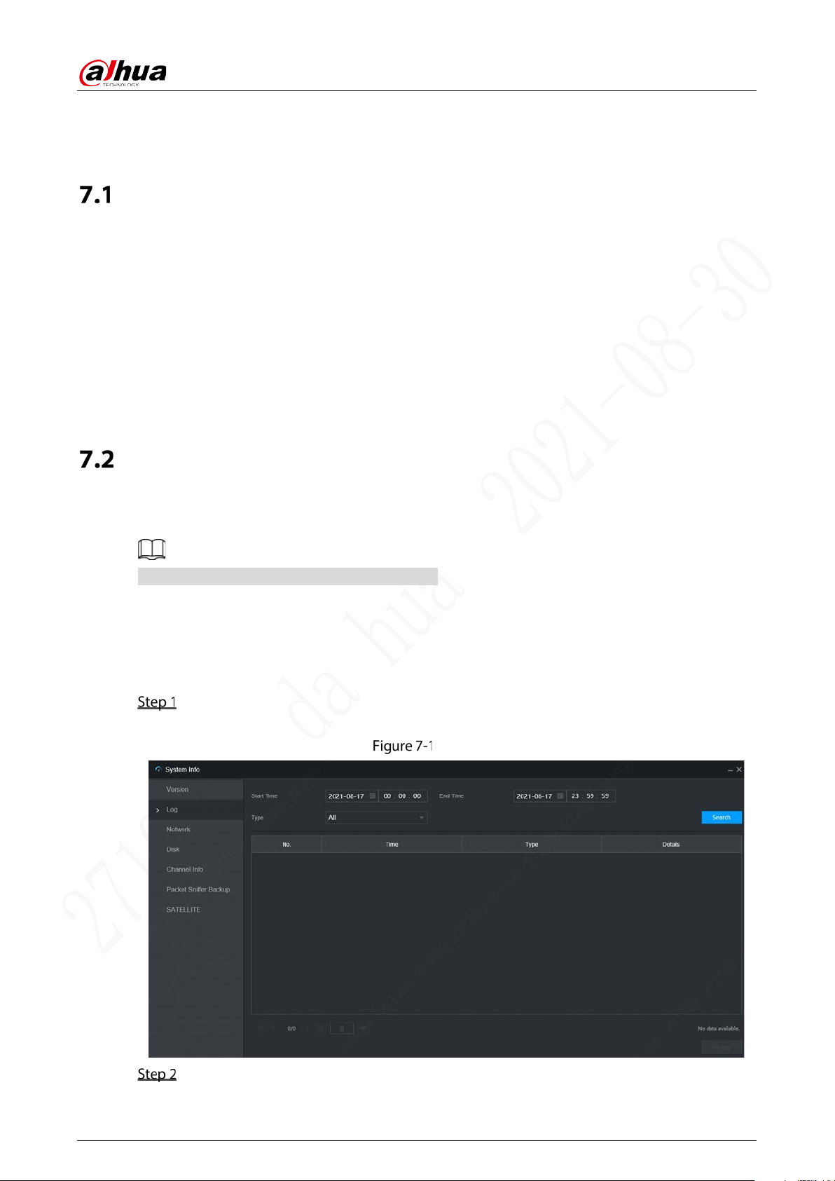
User’s Manual
87
7 System Maintenance
Requirement for Maintenance
To keep the device running normally, it is recommended to manage, backup, and maintain the device.
Check the monitoring screen of Device regularly.
Delete the unused user and group regularly.
Modify the user password every three months.
View the system logs regularly and analyze the data to handle the abnormalities timely.
Back up the system configurations regularly.
Reboot this device regularly.
Upgrade firm wares regularly.
System Information
You can view device version information, logs, network information, HDD information, channel
information, satellite information, and MAC information.
For version information, see “6.1 System Version”.
7.2.1 Log
You can search, view, and back up the logs to local PC.
Select Setting > System Info > Log.
The Log interface is displayed. See Figure 7-1.
Log
Set up Start Time, End Time, and Type.
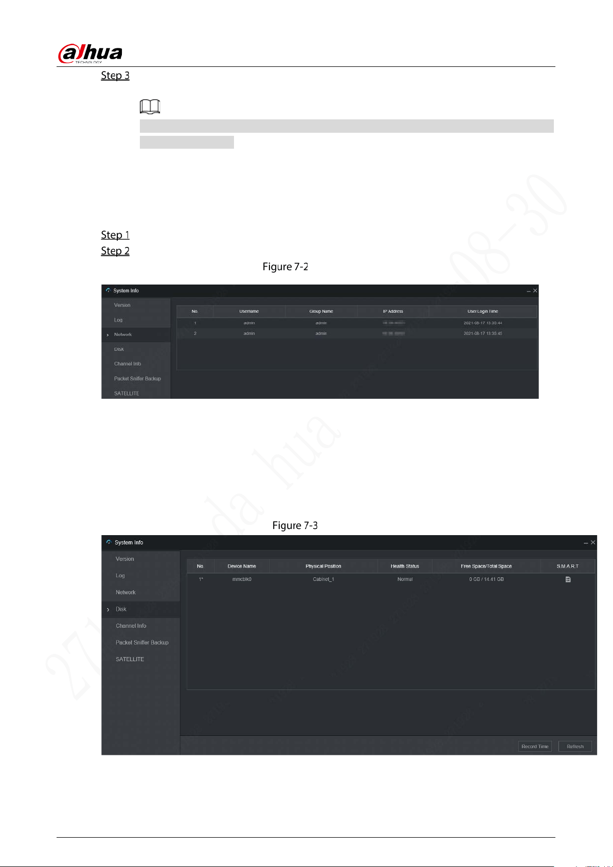
User’s Manual
88
Click Search.
The searched logs are displayed.
Select the log that you want to back up, and then click Backup. You can select the save path
to save the log to PC.
7.2.2 Network Info
You can view IP information of the logged in device.
Select Setting > System Info > Network. The Network interface is displayed. See Figure 7-2.
Click Refresh and the latest network information is displayed.
Network
7.2.3 Disk
You can view the disk information of the device, including device name, physical position, health status,
and free space.
Select Setting > System Info > Disk. The Disk interface is displayed. See Figure 7-3.
Disk
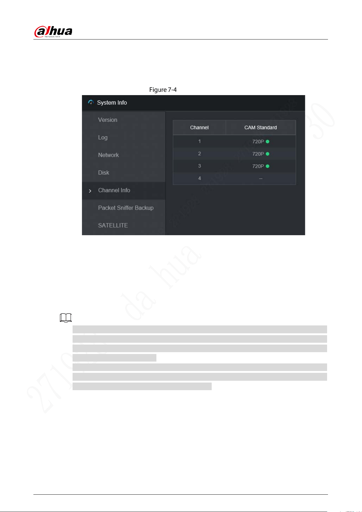
User’s Manual
89
7.2.4 Channel Info
You can view the channel information.
Select Setting > System Info > Channel Info. The Channel Info interface is displayed. See Figure 7-4.
Channel Info
7.2.5 Satellite Info
You can view the satellite positioning information such as module status, positioning status, latitude
and longitude, and search results.
Select Setting > System Info > Satellite. The Satellite interface is displayed. See Figure 7-5.
Click Refresh and the latest satellite information is displayed.
If the GPS module status indicates normal and does not position within five minutes, the GPS
module automatically resets and re-positions. When the positioning information is obtained
again, the GPS module reset times is up to 20, or the device is restarted, you can view the GPS
module reset records in the log.
When the GPS module is short-circuited for more than 10 seconds, the module status is abnormal
and the GPS module is automatically powered off and no longer powered on. After the device is
restarted, the GPS module will be powered on again.
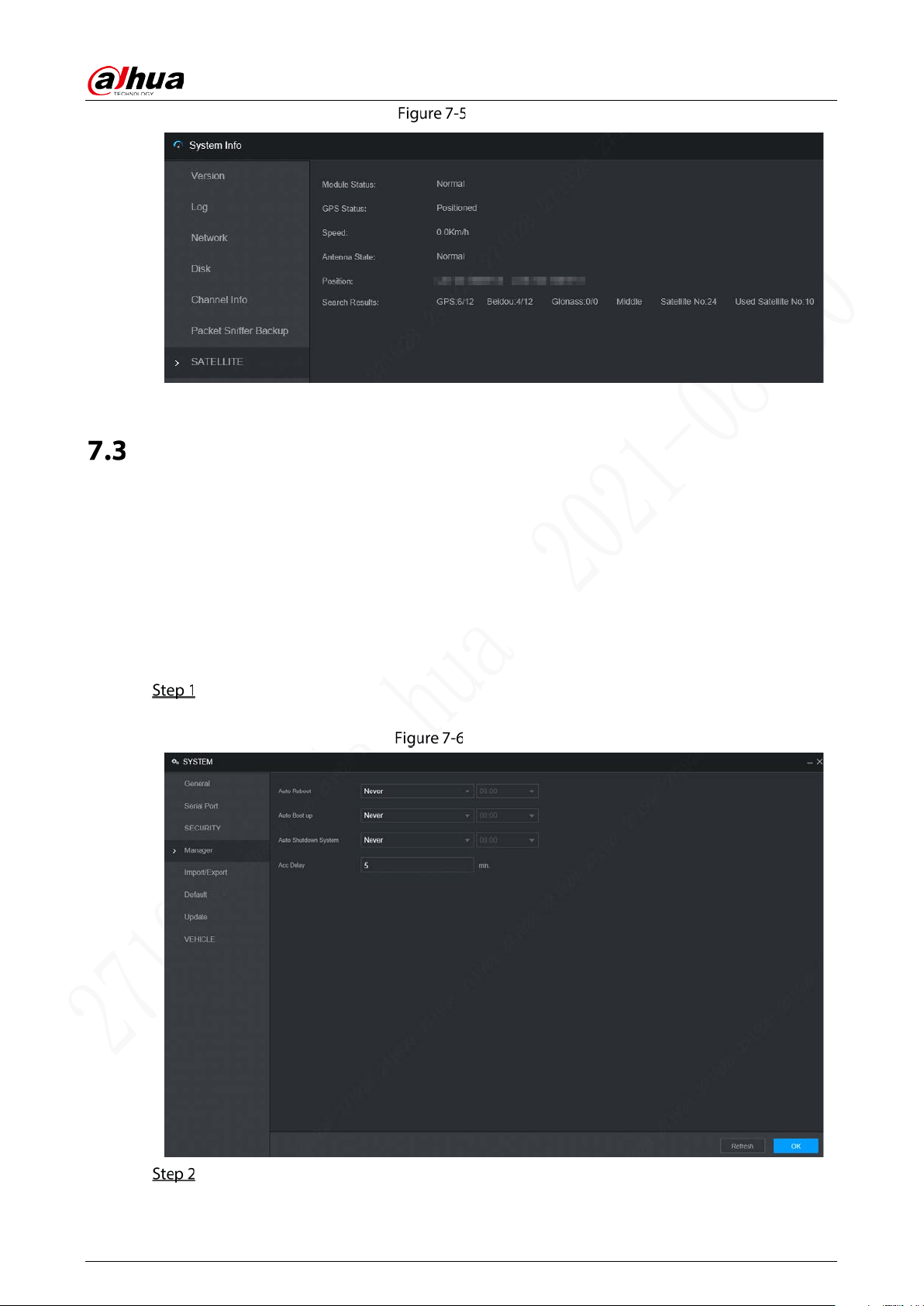
User’s Manual
90
Satellite
Automatic Maintenance
You can configure the automatic maintenance settings such as auto reboot, auto deleting old files,
auto booting up, auto shutdown, and delay for auto shutdown.
7.3.1 Auto Reboot
Once the device is running for a long time, you can set to automatically reboot the device at idle time.
After configuring auto reboot, when the device is working, it reboots according to the schedule.
Select Setting > System > Manager.
The Manager interface is displayed. See Figure 7-6.
Manager
Select the strategy of auto restart.
Select Never, and the device will never restart automatically.

User’s Manual
91
Select Every Day, set the device restart time, and the device will restart automatically at
that time point.
Select Monday to Sunday, set the device restart time, and the device will restart
automatically at that time point every week. If Sunday and 01:00 are selected, the device
will restart automatically at 1:00 every Sunday.
Click OK.
7.3.2 Auto Boot up
After configuring auto start, the device starts automatically at the scheduled time point. If you turn
the vehicle key to ACC before the configured auto start time, the device starts immediately. When the
documentation is powered off, the device will shut down as per the scheduled auto delay for
shutdown.
Select Setting > System > Manager.
The Manager interface is displayed.
Select the strategy of auto start.
Select Never, and the device will never start automatically.
Select Every Day and set the time. When you turn the vehicle key to ACC before this time
point, the device starts immediately.
Click OK.
7.3.3 Auto Shutdown System
After configuring auto shutdown, the device automatically shuts down according to the ACC power
off time and auto boot up setting.
If you have set the time for auto start, there are two situations when the ACC is powered off: If the
system time is between the auto start time and auto shutdown time, the device is turned off at
the configured time point. If the system time is before the auto start time or after the auto
shutdown time, the device is turned off immediately.
If the auto booting up is not set, when the ACC is disconnected, the Device shuts down at the
scheduled time.
Select Setting > System > Manager.
The Manager interface is displayed.
Select the strategy of auto shutdown.
Select Never, and the device will never shut down automatically.
Select Every Day and set the time. The system will shut down as per the ACC power off
time and auto start setting.
Select Every Day for Auto Shutdown, and then enter the specific time.
Click OK.
7.3.4 Acc Delay
After configuring delay for auto shutdown, when ACC is disconnected, the device shuts down as per
the settings of delay for auto shutdown.
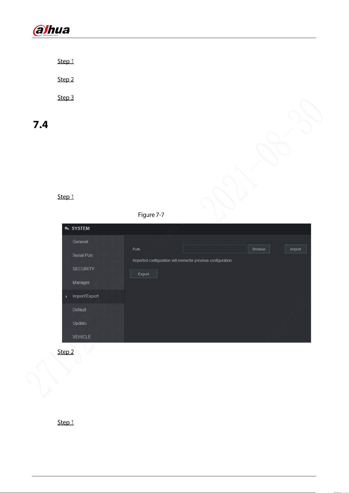
User’s Manual
92
If you enter a delay value that is not 0, the device automatically shuts down after the preset delay.
If you enter 0, the device shuts down as per the auto shutdown settings without delay.
Select Setting > System > Manager.
The Manager interface is displayed.
Configure the ACC delay for shutdown.
The value ranges from 0 through 65535. The fault value is 5.
Click OK.
Backup and Restore
You can back up or restore the web configurations and restore to default settings.
7.4.1 Backing up Configurations
You can back up all the configurations of web.
Select Setting > System > Import/Export.
The Import/Export interface is displayed. See Figure 7-7.
Import/Export (1)
Click Export, and select the backup path.
The system starts backing up configurations.
7.4.2 Importing Configurations
You can use the backed up configurations to quickly configure the device and restore the device
configurations.
Select Setting > System > Import/Export.
The Import/Export interface is displayed. See Figure 7-8.
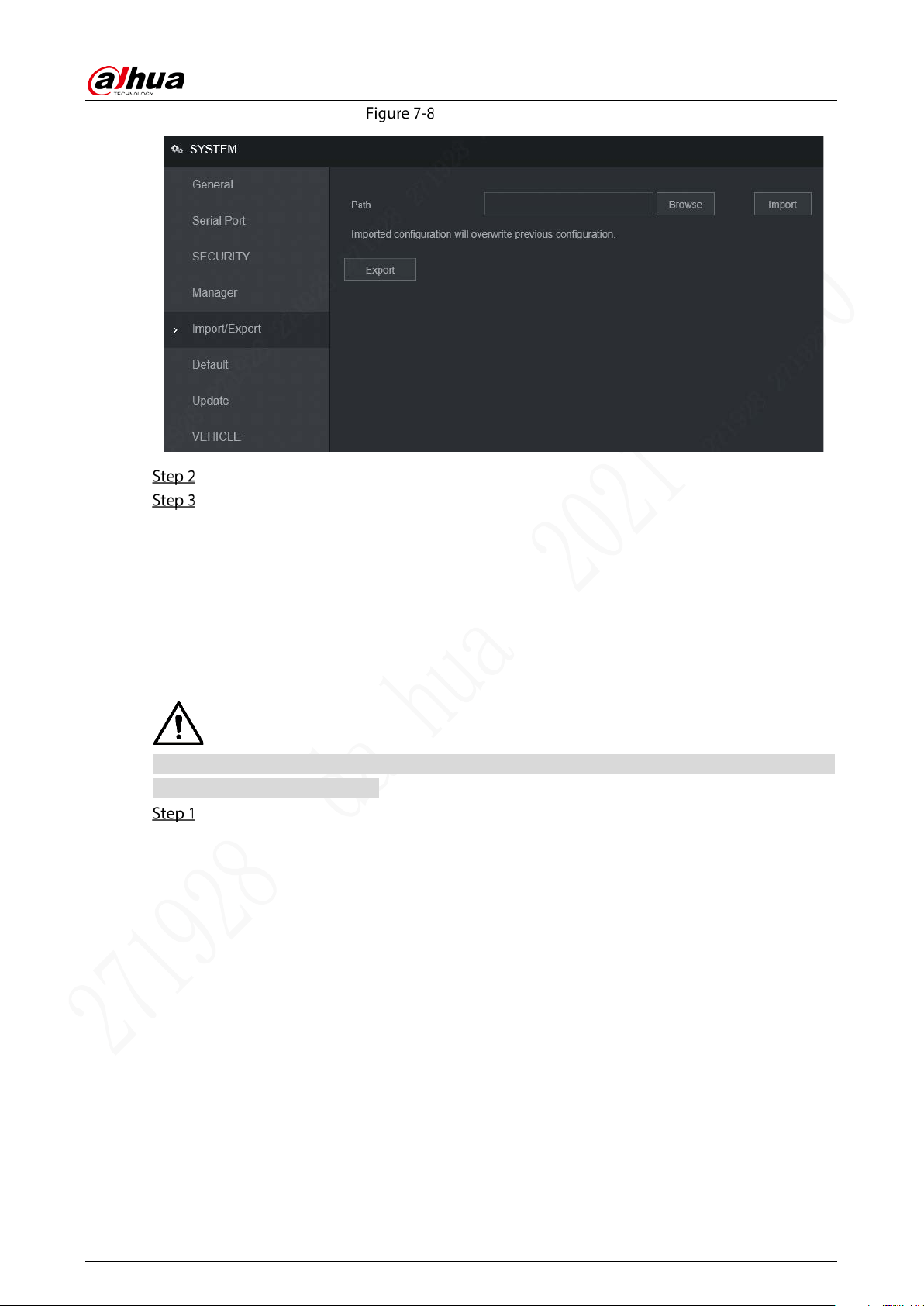
User’s Manual
93
Import/Export (2)
Click Browse, and then select the backup file you want to import.
Click Import.
The system pops up the reboot message. Click OK, the system starts importing the
configurations and reboot the device after importing is completed.
7.4.3 Restoring to Default
You can restore the system to default configurations or the factory default. Only the user with the
default & upgrade authorities can do this.
The corresponding functions will be restored to the factory settings, and your current configurations
will be lost. Proceed with caution.
Select Setting > System > Default.
The Default interface is displayed. See Figure 7-9.
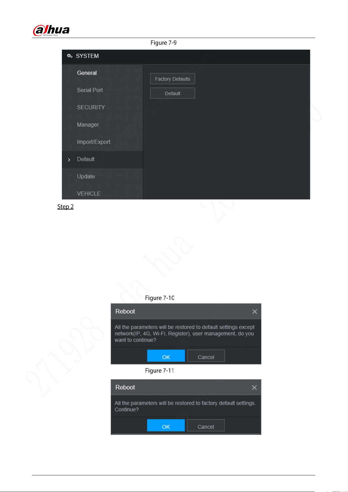
User’s Manual
94
Default
Select the check box of the options that you want to restore to the factory default.
Default: Click Default, and the Reboot dialog box is popped up. See Figure 7-10. Then
click OK. All configurations other than user name, password, security questions and
device IP are restored to the default configuration of the device.
Factory Default: Click Factory Default, and the Reboot dialog box is displayed. See
Figure 7-11. Then click OK, and the system restarts. After the device is restarted, the
system will restore to factory defaults, and the device requires initialization again.
Proceed with caution.
When there is a user operating on the local interface, the factory default settings cannot
be performed until the local user log out.
Reboot (1)
Reboot (2)
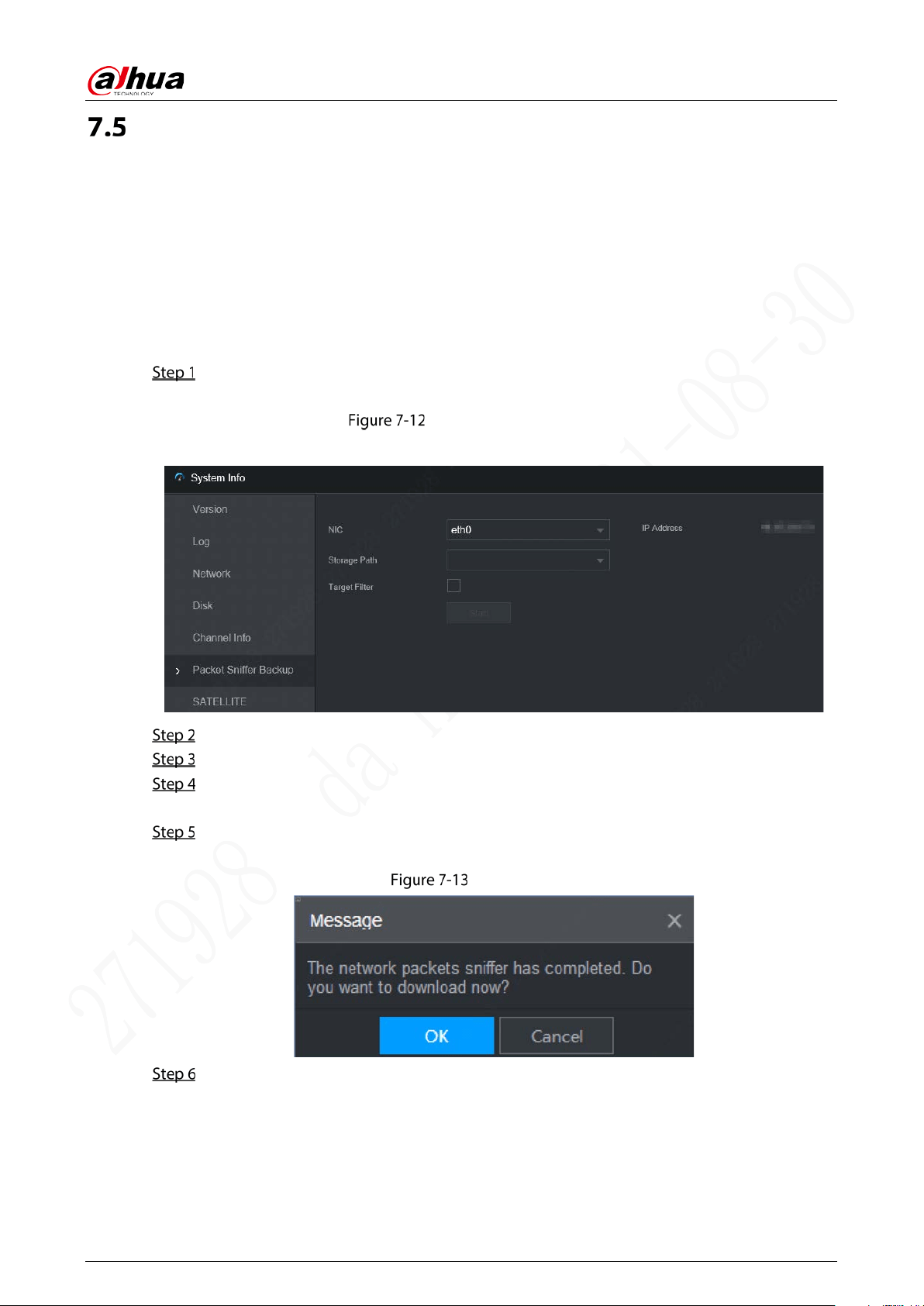
User’s Manual
95
Network Sniffer
The packet data can be provided to the developers or engineers to analyze the network usage status.
Prerequisites
The device being captured is connected to an external backup device.
Procedure
Select Setting > Info > Packet Sniffer Backup.
The Packet Sniffer Backup interface is displayed, see Figure 7-12.
Packet Sniffer Backup
Packet Sniffer Backup
Select the Ethernet card and save path.
Select the Target Filter check box, and then enter the IP address that you want to filter.
Click Start.
The system starts the sniffer, and the data will be stored to the external backup device.
Click Stop.
The Message dialog box is displayed, see Figure 7-13.
Message
Click OK or Cancel to complete the task.
Click OK to download the files locally, which can be viewed in the storage path.
Click Cancel to stop downloading.

User’s Manual
96
8 Logging in to the Device from DSS
Beside from WEB, you can also remotely login the device from Digital Surveillance System (DSS)
For details, see the manual of DSS.

User’s Manual
97
FAQ
If your questions are not solved by following the answers in this document, contact your local
customer service or call customer service at headquarters. We will guide you to solve your problems.
1) Q: Disconnect the constant electricity but the device is still working.
A: Possible reasons:
The UPS setting provides constant power supply to the device when the lithium battery voltage
is above 7V.
2) Q: The device gives squeal after start.
A: Possible reasons:
Connecting to the display and being too close to the camera.
A single channel interface or a large-image multi-channel interface. The first route of sound
comes from a local source.
3) Q: The interface shows that no SIM card is detected.
A: Possible reasons:
SIM card not inserted.
Micro SIM card reversely inserted with its notch facing outward. Follow instructions on the
label to insert the SIM card.
SIM card is damaged.
4) Q: DVR cannot boot up properly.
A: Possible reasons:
The input power is not correct; the input voltage is too low or too high.
Poor contact in the input power cable or incorrect wiring.
HDD is damaged or poor contact between the HDD carrier and HDD.
Main board is damaged.
5) Q: DVR automatically reboots or frequently crashes.
A: Possible reasons:
Input voltage is unstable or too low
The Device is not properly installed, which result in poor contact between components.
Poor heat dissipation and too many dusts result in poor working environment for the Device.
Hardware malfunction.
6) Q: Blank screen in a channel of the display
A: Possible reasons:
A camera is damaged. Replace the damaged camera.
The connection wire is damaged. Replace the damaged connection wire.
7) Q: There is no video output for single channel, multiple channels or all channels
A: Possible reasons:
Incorrect program. Upgrade the correct program.
Image brightness is set as 0. Restore to default settings.
Video input signal is null or too weak.
Channel protection (or screen protection) is set.
Hardware malfunction.

User’s Manual
98
8) Q: Real-time video image is abnormal, such as color and brightness is distorted.
A: There are the following possibilities:
NTSC and PAL settings are not correct, and the image becomes black and white.
Device and monitor resistance is not compatible.
Video network transmission distance is too far or transmission line signal attenuation is too
much.
NVR color or brightness settings are not correct.
9) Q: I cannot search video record in local playback.
A: There are the following possibilities:
Poor contact between the HDD carrier and HDD.
HDD is damaged.
Upgraded a program different from the original program file system.
The video record is overlapped.
The video record is not opened.
10) Q: The local video record is blurry.
A: Possible reasons:
The image quality is too low.
Program read error, bit data is too small, and there is full of mosaic in the screen. Please firstly
try to restart the DVR to solve this problem.
HDD Error
Hardware malfunction.
11) Q: No audio.
A: Possible reasons:
It is not an active speaker.
Audio cable is damaged.
Hardware malfunction.
12) Q: There is audio under monitoring state but no audio under playback state.
A: There are the following possibilities:
Audio function is not enabled.
The corresponding channel does not connect to the camera. Playback is not continuous
when the screen is blue.
13) Q: The time displayed in the video record is wrong.
A: Possible reasons:
Error settings.
Poor battery contact or low voltage.
Crystal oscillator does not work.
14) Q: USB backup error.
A: There are the following possibilities:
Too much data which occupies CPU resources. Please stop recording first and then begin
backup.
Backup device is not compatible.
Backup device is damaged.
The backup device features high power and needs separate power supply.

User’s Manual
99
15) Q: Alarm does not work.
A: Possible reasons:
Incorrect alarm settings.
Incorrect alarm wiring.
Incorrect alarm input signal.
An alarm device is connected to 2 loops at the same time.
16) Q: Messy channel display.
A: Possible reasons::
Incorrect selection of camera type. Auto switch is recommended.
The camera is damaged.
17) Q: Record storage period is not enough.
A: Possible reasons:
Low camera quality, dirty lens, camera installed against the light, or iris not properly adjusted
caused large big rate.
HDD capacity is not enough.
The HDD is damaged.
18) Q: No 3G/4G dial-up. No dial-up IP
A: Possible reasons:
Check if the SIM card is normal.
Check if the SIM card is not in service.
Check if the 3G/4G antenna is connected as intended.
Check if the 3G/4G signals are strong enough.
Try out with another SIM card.
19) Q: 3G/4G platform is not online.
A: Possible reasons:
Check if 3G/4G dial-up is normal.
Check if local active registration is correctly set up.
Check if the sever terminal is correctly set up.
20) Q: No GPS data.
A: Possible reasons:
Check if the GPS antenna is connected as intended.
Make sure the GPS antenna is in a place where signals are not blocked.
21) Q: GPS drifting and produces speed for no reason.
A: Possible reasons:
Weak GPS signal.
22) Q: Video record is silent.
A: Possible reasons:
Check if a normal analog camera is connected. Only HDCVI camera with audio input supports
audio.

User’s Manual
100
Storage Capacity Calculation
When the device is installed for the first time, make sure the HDD (or TF card) is installed.
Capacity calculation formula:
Total capacity (M) = Channel quantity × Demand time length (hour) × storage capacity occupied per
hour (M/hour)
Recording time calculation formula:
Recording time (hour) = Total capacity (M)
Storage capacity occupied per hour (M/hour) × Channel quantity
The device adopts H.264/H.265 compression technology, which features a large dynamic range.
Therefore, when calculating HDD capacity, you should accord to the bit rate to evaluate the file size
generated per hour from each channel.

User’s Manual
101
Legal Information
Copyright
ZHEJIANG DAHUA VISION TECHNOLOGY CO., LTD. All rights reserved.
Any content of this document may not be reproduced, transmitted, distributed or stored in any form
by anyone without prior written permission of Zhejiang Dahua Vision Technology Co., Ltd. (hereinafter
referred to as “Dahua”).
The products described in this document may contain the software that belongs to Dahua or the third
party. Without the prior written approval of the corresponding party, any person cannot (including
but not limited to) copy, distribute, amend, abstract, reverse compile, decode, reverse engineer, rent,
transfer, sublicense the software.
Trademarks
, , , , and the trademarks or
registered trademarks of Dahua.
HDMI logo, HDMI, and High-Definition Multimedia Interface are trademarks or registered
trademarks of HDMI Licensing LLC. This product has been authorized by HDMI Licensing LLC to
use HDMI technologies.
VGA is the trademark of IBM.
The Windows logo and Windows are trademarks or registered trademarks of Microsoft.
All the company names and trademarks mentioned herein are the properties of their respective
owners.
Disclaimer
To the maximum extent permitted by applicable laws, in no event shall we be liable for any special,
incidental, indirect, or consequential damages or any damages whatsoever on, including without
limitation, loss of profit, data, goodwill, files, or expected savings, arising out of or in any way
connected with the relevant contents and described products in this document.
All products described in this document are provided on an "as-is" basis. Unless required
otherwise by applicable laws, this document is provided without a warranty of any kind, either
express or implied, including but not limited to, merchantability, degree of satisfaction, fitness for
a particular purpose, or non-infringement.
Compliance to Export Control
Dahua complies with applicable export control laws and regulations, and requirements on export, re-
export, and transfer of hardware, software, and technologies. You are supposed to fully understand
and strictly comply with domestic and international laws and regulations on export control related to
the products described in this document.
Privacy Protection Notice
As the device user or data controller, you might collect personal data of others' such as face,
fingerprints, car plate number, Email address, phone number, GPS and so on. You need to be in
compliance with the local privacy protection laws and regulations to protect the legitimate rights and
interests of other people by implementing measures include but not limited to: providing clear and
visible identification to inform data subject the existence of surveillance area and providing related
contact.

User’s Manual
102
About the Manual
The Manual is for reference only. If there is inconsistency between the Manual and the actual
product, the actual product shall prevail.
We are not liable for any loss caused by the operations that do not comply with the Manual.
The Manual would be updated according to the latest laws and regulations of related regions. For
detailed information, see the paper User's Manual, CD-ROM, QR code or our official website. If
there is inconsistency between paper User's Manual and the electronic version, the electronic
version shall prevail.
All the designs and software are subject to changes without prior written notice. The product
updates might cause some differences between the actual product and the Manual. Please
contact the customer service for the latest program and supplementary documentation.
There still might be deviation between the actual value of some data and the value provided, if
there is any doubt or dispute, please refer to our final explanation.
Upgrade the reader software or try other mainstream reader software if the Manual (in PDF format)
cannot be opened.

User’s Manual
103
Cybersecurity Recommendations
Declarations
By connecting the product into Internet, you have to bear related risks on your own account,
including but not limited to those related to cyber attacks, hacker attacks, and virus infections. It
is advised to enhance the protection for your network data, device data, and personal information.
We recommend you to take necessary actions to enhance the security of your devices and
network, such as changing passwords and using strong passwords whenever possible, changing
passwords regularly, and updating firmware to the latest version. We are not liable for any
malfunction, information leak or other problems of the product caused thereby, but we will
provide security services for the product against these risks.
To the extent not explicitly prohibited by applicable laws, we, our employees, licensors, or
affiliated companies are not liable for any loss of profit, revenue, sales, or data, or the cost for
purchasing substitute goods or services, property loss, personal injury, business discontinuity,
commercial information loss, or any special, direct, indirect, incidental, consequential, economic,
covering, or punitive damages caused by using or not able to use this product or service,
regardless of on which liability theory (contract, tort, fault, or others) these damages are based,
even if we, our employees, licensors, or affiliated companies have been advised of the possibility
of such damages. Some jurisdictions do not allow limitations on liabilities for personal injuries,
incidental or consequential damages. If you are in one of these jurisdictions, these limitations
might not apply to you.
Our total compensation for all your damages is limited to the amount you paid for buying our
products or services, except where relevant laws apply if our negligence has caused personal
injuries or deaths.
Recommendations
Mandatory actions to be taken for cyber security:
1. Use a strong password
Refer to the following recommendations for setting up the password:
The length should not be less than 8 characters
A strong password is comprised of at least two of these three character types: letters in upper
and lower cases, numbers, and special characters.
Do not contain the user name in its forward or reverse sequence.
Do not use continuous characters, such as 123 and abc.
Do not use repeated characters, such as 111 and aaa.
2. Timely update firmware and client software
As is standard procedure in the tech-industry, the firmware of devices should be timely
updated to the latest version to ensure the system is current with the latest security patches
and fixes. With the device connected into Internet, it is recommended to turn on automatic
online update detection to timely get firmware updates launched by providers.
You are recommended to download and use the latest client software.

User’s Manual
104
Recommended measures to enhance cybersecurity:
1. Physical protection
Physical protection is recommended for devices (especially storage devices), such as placing
them in a special room, special cabinet, and well conduct access control and key control to
prevent damages to hardware and external devices (U disk, serial ports) by unauthorized
persons through physical contact.
2. Change Passwords Regularly
Regularly change the passwords to your devices to help ensure that only authorized users are
able to access the system.
3. Timely set up and update password resetting information
This device supports password reset. To reduce the risk of this function being attacked by
hackers, it is recommended to timely set up password reset, including reserved phone
number/email, and security questions. If any of such information changes, update the password
reset in time. When setting up security questions, set up an answer that is difficult for someone
to guess their way into your system.
4. Enable account lock-down
Account lock-down is enabled by default. To keep your Account safe, it is recommended to keep
this setting. After hackers fail multiple attempts to hack passwords, the corresponding Account
and source IPs are locked.
5. Change HTTP and other default service ports
These ports can be changed to any set of numbers between 1024-65535. Avoiding the default
ports reduces the risk of hackers being able to guess which ports you are using.
6. Enable HTTPS
Enable HTTPS to access Web services through safe channels.
7. Bind MAC Address
Bind the IP and MAC address of the gateway device to reduce the risk of ARP deception.
8. Reasonably allocate account and permission
Add users properly according to business and management needs, and allocate minimum sets
of permissions to them.
9. Turn off Unnecessary Services and Use Safe Modes
If not needed, SNMP, SMTP and UPnP can be turned off to reduce the risks for the device.
If necessary, it is strongly recommended to use safe modes, including but not limited to:
SNMP: Select SNMP v3 and set a stronger encryption password and authentication password.
SMTP: Select TLS to access to the email server.
FTP: Select SFTP and set a strong password.
AP hotspot: Select WPA2-PSK encryption mode and set a strong password.
10. Audio and Video Encrypted Transmission
If your audio/video data includes important or sensitive contents, use encrypted transmission to
make it more difficult for someone to steal your data.
11. Security Audit
Review online users: Do this from time to time to find out illegal login, if any.
Review device log: This gives you the IP data of a device trying to login and the critical
operation information of users already in the login status.
12. Network Log

User’s Manual
105
Limited storage capacity of the device cannot store many logs for a long time. If you need to
save logs for long, enable online log to ensure key logs are synced to the online log server for
easy back tracking.
13. Building Safe Network Environment
To keep the device safer and reduce network risks, we recommend you to:
Turn off the port mapping of the router to prevent external networks from directly accessing
services of router intranet devices.
Divide network into different partitions as needed: If two subnetworks do not have to
establish communications, use VLAN or gatekeeper for network division.
Build up the 802.1x access authentication to reduce the risk of illegal terminals connecting
with your private networks.
Enable device IP/MAC address filtering to limit the hosts that can access the device.
More Information
Please go to PSIRT on the official Dahua website for security notices and the latest security advisories.

User’s Manual
106