Loading ...
Loading ...
Loading ...
12
3
0
9
6
1
2
TORK
1
2
12
3
0
9
6
1
2
T
O
R
K
1
2
9
2
TO
P
3
6
0
12
3
0
9
6
1
2
TORK
1
2
12
3
0
9
6
1
2
T
O
R
K
1
2
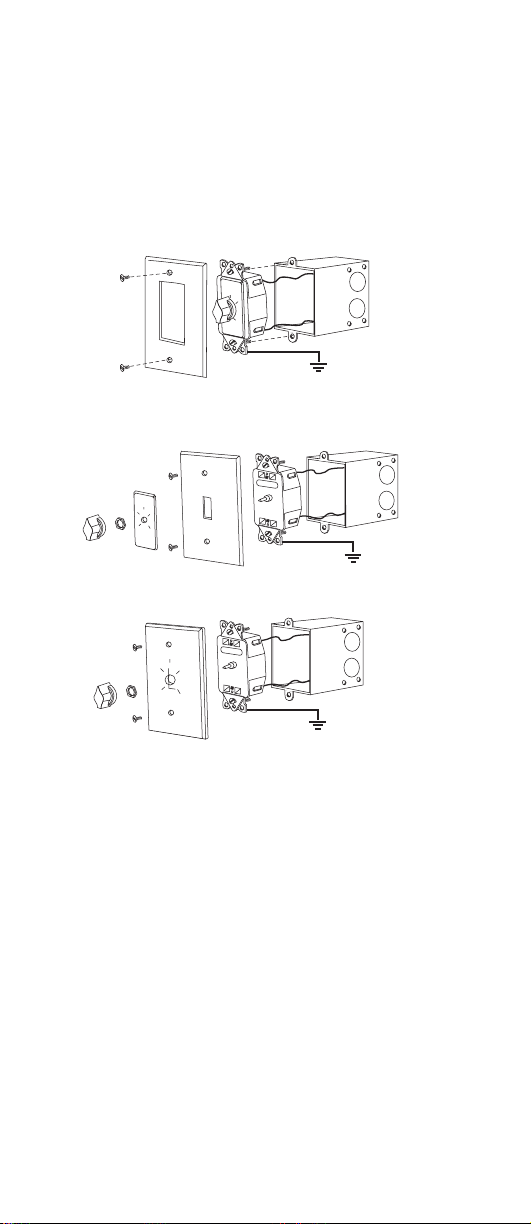
MECHANICAL INSTALLATION
1. Insert wired timer into a 2-1/2”deep, UL listed wall box with
“TOP”(indicated on timer body) in proper position.
2. Fasten unit to outlet box using two screws provided.
3. Install wall plate.
A SERIES - USING DECORATOR STYLE WALL PLATE (not included).
THIS UNIT MAY BE USED IN SINGLE OR MULTIPLE GANG INSTALLATIONS.
A SERIES - USING STANDARD SWITCH PLATE (not included). THIS
UNIT MAY BE USED IN SINGLE OR MULTIPLE GANG INSTALLATIONS. Remove
and replace knob, hexnut, and faceplate to install wall plate as shown.
C SERIES - USING METAL WALL PLATE SUPPLIED.
4. Restore power.
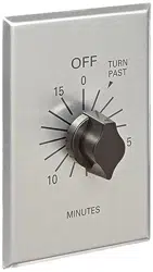
OPERATING INSTRUCTIONS
Turn knob clockwise to desired time period.Regardless of time-on period
desired, knob must first be rotated past “TURN-PAST”point indicated on face.
It may then be turned back to a shorter time period if desired.Timer will
automatically turn “OFF”current at end of period. Some timers are equipped
with a hold feature which will hold current “ON”without operation of the
timing mechanism:timing will not start unless knob is turned clockwise to a
time period.To engage hold feature turn knob counter clockwise until knob
pointer points to HOLD.
ONE YEAR LIMITED WARRANTY
ONE YEAR LIMITED WARRANTY: If this product fails because of a manufacturing defect within one year after
purchase, we will, at our option, either repair or replace it at no charge. Our warranty does not cover damage
caused by accident, abuse or misuse. We assume no further liability with respect to the sale or use of this product.
THIS WARRANTY IS IN LIEU OF ALL OTHER WARRANTIES, EXPRESSED OR IMPLIED, INCLUDING THE WARRANTY
OF MERCHANTABILITY. We make no warranty with respect to the fitness of any goods for the users particular
application. This warranty gives you specific legal rights, and you also may have other rights which vary from
state to state. It is our intent to provide accurate and current specification information. However, in the interest of
product improvement, TORK may alter the specifications or constructional details without prior notice.
9
2
TO
P
3
6
0
12
3
0
9
6
1
2
T
O
R
K
1
2
9
2
TO
P
3
6
0
12
3
0
9
6
1
2
TORK
1
2
INSTALLATION
1. Après son câblage, installez la minuterie dans un boîtier mu al d’une
profondeur de 2,5 pouces, avec l’indication ‘TOP’(inscrite sur le bâtit) en haut.
2. Utilisez les deux vis fournies pour fixer l’appareil au boîtier mural.
3. Installez la plaque murale.
SÉRIE A - UTILISATION DE PLAQUE DÉCORATIVE (non fournie).
CET APPAREIL PEUT SERVIR AUX INSTALLATIONS À COMMANDE UNIQUE OU
MULTIPLE.
SÉRIE A - UTILISATION DE PLAQUE STANDARD (non fournie). CET
APPAREIL PEUT SERVIR AUX INSTALLATIONS À COMMANDE UNIQUE OU
MULTIPLE. Pour installer une plaque, enlevez et remplacez le bouton, l’écrou et
la plaque comme indiqué ci-dessous.
SÉRIE C - UTILISATION DE LA PLAQUE MÉTALLIQUE FOURNIE.
4. Remettez le courant.
MODE D’EMPLOI
Tournez le bouton à droite jusqu’au délai de temporisation voulu. Quel que soit
ce délai, le bouton doit être tourné au delà du point ‘TURN-PAST’indiqué sur la
façade.Il peut être alors ramené à un délai plus court si nécessaire.La minuterie
coupera le courant automatiquement en fin de délai. Certaines minuteries
sont équipées d’un dispositif de dérivation qui permet de maintenir le courant
sans l’intervention de la minuterie:la minuterie ne fonctionnera alors qu’après
avoir réglé l’appareil en tournant le bouton à droite.Pour activer le dispositif de
dérivation, tournez le bouton à gauche jusqu’à ce que le pointeur se trouve face
au repère ‘HOLD’.
FOR TECHNICAL SUPPORT
PARA COMUNICARSE CON EL SERVICIO TÉCNICO
[email protected] • 888.500.4598
FOR TECHNICAL SUPPORT: SOUTIEN TECHNIQUE
INSTALACIÓN MECÁNICA
1. Inserte los cables del interruptor dentro de una caja de pared de 2 y 1/2
pulgadas de profundidad con la palabra “TOP” (ubicada en el cuerpo del
interruptor) en la posición indicada.
2. Fije la unidad al frente de la caja usando los tornillos pro vistos para este fin.
3. Coloque la placa de pared sobre el interruptor y fije.
SERIE A - USANDO UNA PLACA DECORATIVA (no incluida).
ESTA UNIDAD PUEDE SER USADA EN INSTALACIONES MÚLTIPLES O SENCILIAS.
SERIE A - USANDO UNA PLACA ESTÁNDAR (no incluida).
ESTA UNIDAD PUEDE SER USADA EN INSTALACIONES MÚLTIPLES O SENCILIAS.
SERIE C - USANDO UNA PLACA METÁLICA INCLUIDA.
4. Restablezca la energia.
INSTRUCCIONES DE OPERACIÓN
A. Coloque la perilla indicadora siguiendo el sentido de las manecilias del reloj
en la posición que indica el tiempo predeterminado del interruptor.
B. Independientemente del periodo deseado la perilla indi cadora deberá ser
primeramente clocada después de la indicación “TURN”- “PAST”(indicado en la
placa).
C. A partir de allí podrá retornar la perilla a un periodo más corto si así lo desea.
D. El interruptor desconectatá la carga automáticamente después de terminado
el periodo.
Loading ...
Loading ...