Loading ...
Loading ...
Loading ...
Rev. A 10/14
2
5084415
Rev. A 10/14
7
5084415
Ubique las partes restantes de la Motor de bolsa tornillería para Montar
los Enrejados y la Hélice en el Motor.
1. Instale la Parrilla Trasera en el Motor, alineando los seis agujeros de
la parrilla con los seis agujeros roscados de la brida de montaje del
motor. Instale (6) tornillos hexagonales de 10-32 x 5/16 a través de la
parrilla trasera y dentro de la brida de montaje. apréte firmemente
los (6) tornillos. (Figura 6)
2. Empuje la Hélice Del Ventilador en el Eje Del Motor, centrando el
Cubo orientado en sentido opuesto al motor, hasta que tope contra el
eje. (Inseto A) Alinee un perno de cabeza cuadrada con la superficie
plana del eje del motor. APRÉTELO BIEN FIRME CON UNA LLAVE
DE TUERCAS AJUSTABLE. Si no se apreta firmemente el perno
se puede causar daños al ventilador y/o lesiones personales.
3. Sostenga la Parrilla Delantera de modo que el nombre, en el centro,
esté al derecho y horizontal. Empezando en la parte superior: Fije
la Parrilla Delantera a la Parrilla Trasera deslizando los ganchos de
alambre de la Parrilla Delantera sobre el anillo exterior de la Parrilla
Trasera. (Figura 7 / Detalle A) Será necesario usar un destornillador
en los ganchos inferiores para terminar el armado. Párese detrás del
ventilador. Deslice la punta plana del destornillador entre las Parrilla
Delantera y Parrilla Trasera, junto a uno de los ganchos sin fijar.
(Figura 7 / Detalle B) Tire del mango del destornillador hacia arriba
hacia la Parrilla Trasera. Empuje el gancho de la Parrilla Delantera
para deslizarlo sobre el anillo exterior de la Parrilla Trasera. Repita
el procedimiento con los ganchos restantes.
PRECAUCIÓN: NO DOBLE LOS ALAMBRES EN LAS PARRILLAS
DELANTERA Y TRASERA.
MONTAJE DE ENREJADO Y HÉLICE
Ubique la Motor de bolsa tornillería para Montar el Conjunto de
Columna y Motor.
1. Deslice la sección plana del Tubo Superior del Conjunto de
Columna junto al Cuello del Conjunto de Motor. Alinee el orificio
de 1/2” de diámetro en la sección plana del Tubo Superior del
/Conjunto de Columna con el orificio de 1/2” de diámetro del
Conjunto de Motor. (Figura 4)
2. Introduzca el Tornillo Hexagonal de 1/2” X 1” (cabeza de 3/4”) a
través del Cuello del Motor y el Conjunto del Tubo Superior. Coloque
una Arandela de Fijadora Hendida de 1/2” de diámetro y luego la
Tuerca Hexagonal de 1/2” de diámetro (cabeza de 3/4”) y apriételas
completamente con una llave de tuerca ajustable. (Figura 4)
3. Desde el mismo costado del Cuello del Motor, introduzca un Tronillo
de Carruaje de 1/4-20 X 1 5/8” a través de la Ranura con Forma
de Arco en el Cuello del Motor y del Orificio en el Tubo Superior
del Conjunto de Columna. (Figura 4)
Para Fijar: Coloque una Arandela Plana de 1/4”, una Arandela Fijadora
de Diente Interno, una segunda Arandela Plana, y luego apriete la
Perilla Ajustable sobre las roscas restantes.
4. Conecte la cadena de tiro al interruptor de velocidad del motor
si así lo desea.
Figura 4
MONTAJE DE COLUMNA Y MOTOR
1. Coloque el Conjunto de Columna y Motor sobre el piso al costado
del Conjunto de Base. Incline el Conjunto de base hacia arriba,
sobre uno de sus extremos. Levante el tubo inferior del Conjunto
de Columna e introdúzcalo dentro del Patín de Montaje. (Figura 5)
2. Apriete el Tornillo de Cabeza Cuadrada de 3/8-16 X 1” dentro del
Patín de Montaje.
3. Incline todo el conjunto hasta que quede en posición vertical.
PROCURE QUE LOS TORNILLOS INDICADOS EN LOS PASOS
CORRESPONDIENTES AL CONJUNTO DE COLUMNA Y MOTOR ESTÉN
FIJOS ANTES DE COLOCAR EL VENTILADOR EN POSICIÓN VERTICAL.
4. Afloje el Tornillo de Cabeza Cuadrada de 3/8-16 X 1” en el Patín de
Montaje. Esto permitirá que la Columna se asiente en la parte inferior
de la Base después de colocar el Ventilador en posición vertical.
5. Apriete el Tornillo de Cabeza Cuadrara de 3/8-16 X 1” en el Patín de
Montaje.
MONTAJE DE COLUMNA / MOTOR
A LA BASE
El motor verdadero no mostró para la
vista de hardware de detalle.
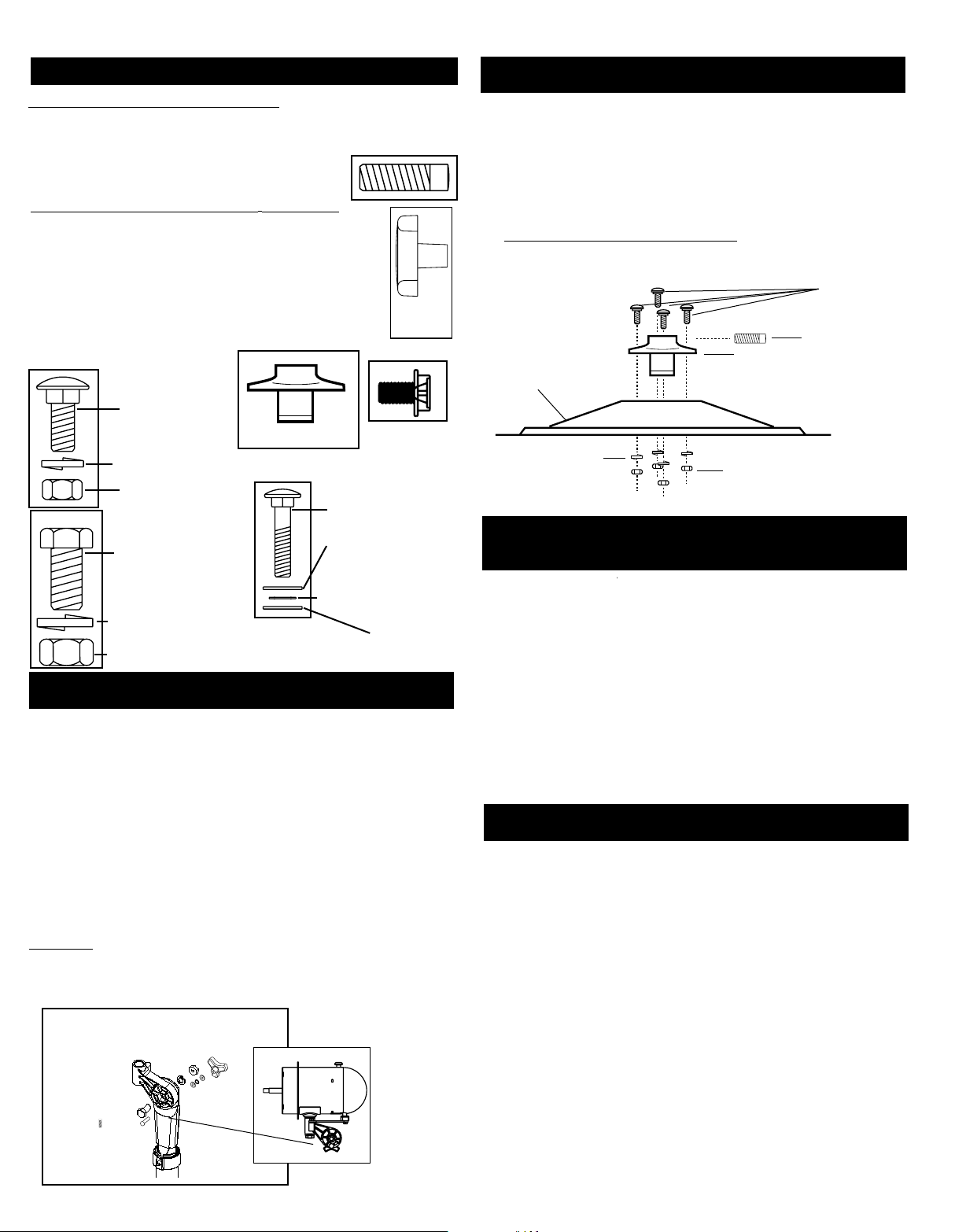
MONTAJE DE LA BASE
Ubique la Bolsa de Herrajes “A” para Montar la Base. (Figura 1)
1. Coloque la Base sobre el piso.
2. Encaje el Patín de Montaje a través del orificio grande en el centro
de la Base.
3. Introduzca (4) Tornillos de Carruaje de 3/8-16 X 1” a través del Patín
de Montaje y la Base.
4. Incline la Base y fije un Tornillo de Carruaje a la vez, colocando
primero una Arandela Fijadora Hendida de 3/8” y después una
Tuerca Hexagonal de 3/8-16. NO APRIETE TOTALMENTE TODAVÍA.
Repita el procedimiento anterior con los Tornillos restantes.
5. REGRESE Y APRIETE TOTALMENTE cada Tuerca Hexagonal de
modo que el Patín esté fijo con firmeza a la Base.
6. Introduzca el Tornillo de Cabeza Cuadrada de 3/8-16 X 1” dentro
del Patín de Montaje.
Figura 1
Tornillo De Cabeza
Cuadrada
Patín De Montaje
Base
Tuercas Hexagonales (4)
Arandelas Figadora
Hendida (4)
Tornillo De Carruaje (4)
BOLSA DE TORNILLERÍA A:
(1) Brida de montaje
(1) Perno de cabeza cuadrada (3/8-16 x 1 pulg)
(4) Pernos de carruaje (3/8-16 x 1 pulg)
(4) Arandelas de seguridad divididas (3/8 pulg)
(4) Tuercas hexagonales (3/8-16)
BOLSA TORNILLERÍA DE MOTOR
(1) Perno Hexagonal (1/2-13 X 1 pulg)
(1) Arandela de Seguridad Dividida (1/2 pulg)
(1) Tuerca Hexagonal (1/2-13)
(1) Perno de Carruaje (1/4-20 X 1 5/8)
(1) Arandela de Seguridad (1/4 pulg, dientes internos)
(2) Arandela planas (1/4 pulg)
(1) Perilla Ajustable
(6) Tornillos de Cabeza Hexagonal (10-32 X 5/16 pulg)
(1) Cordón de Tirar
Pernos de carruaje
(3/8-16 X 1” pulg)
Arandelas de seguridad
divididasr (3/8 pulg)
Tuercas hexagonales
(3/8-16)
Brida de Montaje
Perno de
cabeza cuadrada
(3/8-16 X 1 pulg)
Tornillos de
cabeza
hexagonal
(10-32 x 5/16 pulg)
Perno hexagonal
(1/2-13 X 1 pulg)
Arandela de seguridad
dividida (1/2 pulg)
Tuerca hexagonal (1/2- 13)
Perilla
Ajustable
Perno de carruaje
(1/4-20 X 1 5/8 pulg)
Arandelas planas
(1/4 pulg)
Arandelas planas
(1/4 pulg)
Arandela de Seguridad
(1/4 pulg,
dientes internos)
CONTENIDO DE LA BOLSA DE HERRAJES
SAVE THESE INSTRUCTIONS
IMPORTANT SAFETY INFORMATION
When using electrical appliances, basic precautions should always be followed to reduce
the risk of fire, electrical shock and injury to persons, including the following:
Read all instructions before using this Fan.
TO REDUCE THE RISK OF FIRE, ELECTRICAL SHOCK OR PERSONAL INJURY, ALWAYS
FOLLOW THESE IMPORTANT SAFETY INSTRUCTIONS AND WARNINGS:
DO NOT use this fan to ventilate areas where flammable liquids or vapors are used, stored or are present, including paints,
gasoline, varnishes, floor refinishing products or solvents. ALWAYS read and follow all warnings and instructions on the
containers for these products!
ALWAYS be sure the plug fits tightly into the outlet. When plugs fit loosely into outlets, they may slip partially out of the
outlet and create a poor connection. This may cause outlets to overheat and create a potential fire hazard. Outlets in this
condition should be replaced by a qualified electrician.
ALWAYS unplug the power cord when servicing, cleaning or moving the Fan. DO NOT use the ON/OFF switch as the sole
means of disconnecting power. NEVER leave children unattended when the Fan is on or plugged in. ALWAYS turn off and
unplug the Fan when not in use.
BE CERTAIN that the power source for the Fan is 120V AC. DO NOT plug the Fan into 240V or other power source.
The power cord is equipped with a three-prong grounded plug that must be inserted into a matching receptacle. Under no
circumstances should the grounding prong be cut off the plug. Where a two-prong wall receptacle is encountered, it must be
replaced with a properly grounded three-prong receptacle installed in accordance with the National Electrical Code (NEC) and
all applicable local codes and ordinances. This work must be done only by a qualified electrician, using copper wire only.
DO NOT USE A THREE-PRONG TO TWO-PRONG ADAPTER. IMPROPER CONNECTION MAY CREATE THE RISK OF ELEC-
TRICAL SHOCK. USE OF SUCH ADAPTERS IS NOT PERMITTED IN CANADA.
• AVOID the use of extension cords, power strips, power taps, outlet style air fresheners or other cord connected device, as these
devices may overheat and cause a fire hazard.
•DO NOT route power cord under rugs, carpets, runners or furniture. This may damage the cord or cause it to overheat creating a fire
hazard.
•ALWAYS place the Fan on a stable, flat, level surface while in operation to prevent the Fan from overturning.
•NEVER insert or allow fingers or objects to enter grill openings while Fan is in operation or injury and/or damage to the Fan may occur.
•DO NOT block, cover or obstruct air flow to or from the fan while in operation.
•DO NOT use this Fan outdoors or near water or wet locations such as a bath tub, pool or hot tub. Use of this Fan in a wet location
may create a shock hazard.
•DO NOT run cord under carpeting. Do not cover cord with throw rugs, runners, or similar coverings. Do not route cord under furniture
or appliances. Arrange cord away from traffic area and where it will not be tripped over.
•NEVER use a single extension cord to operate more than one Fan or other electrical device.
•DO NOT use this Fan if it has been damaged or is not functioning properly.
•THIS FAN DOES NOT MEET THE REQUIREMENTS OF NEC ARTICLE 547-7 (2008).This Fan is not suitable for use in agricultural
facilities including areas where livestock, poultry or other animals are confined. Please refer to National Electric Code (NEC) Article
547-7 (2008), or applicable state or local codes or standards relating to electrical requirements for agricultural buildings.
•THIS FAN DOES NOT MEET THE REQUIREMENTS OF NEC ARTICLE 500 (2008).This Fan is not suitable for use in hazardous
locations. Please refer to National Electric Code (NEC) Article 500 or applicable state or local codes or standards relating to electrical
requirements for hazardous locations.
NOTICE: This equipment has been tested and found to comply with the limits for a Class B digital device, pursuant to Part 15 of the
FCC Rules. These limits are designed to provide reasonable protection against harmful interference in a residential installation. This
equipment generates uses and can radiate radio frequency energy and, if not installed and used in accordance with the instructions,
may cause harmful interference to radio communications. However, there is no guarantee that interference will not occur in a particu-
lar installation. If this equipment does cause harmful interference to radio or television reception, which can be determined by turning
the equipment off and on, the user is encouraged to try to correct the interference by one or more of the following measures: Reorient
or relocate the receiving antenna. Increase the separation between the equipment and receiver. Connect the equipment into an outlet
on a circuit different from that to which the receiver is connected. Consult the dealer or an experienced radio/TV technician for help.
The user is cautioned that changes and modifications made to the equipment without the approval of manufacturer could void the
user’s authority to operate this equipment.
CAUTION
Loading ...