Loading page 1...
Loading page 2...
Loading page 3...
Loading page 4...
Loading page 5...
Loading page 6...
Loading page 7...
Loading page 8...
Loading page 9...
Loading page 10...
Loading page 11...
Loading page 12...
13
3. CONNECTIONS (CONT’D)
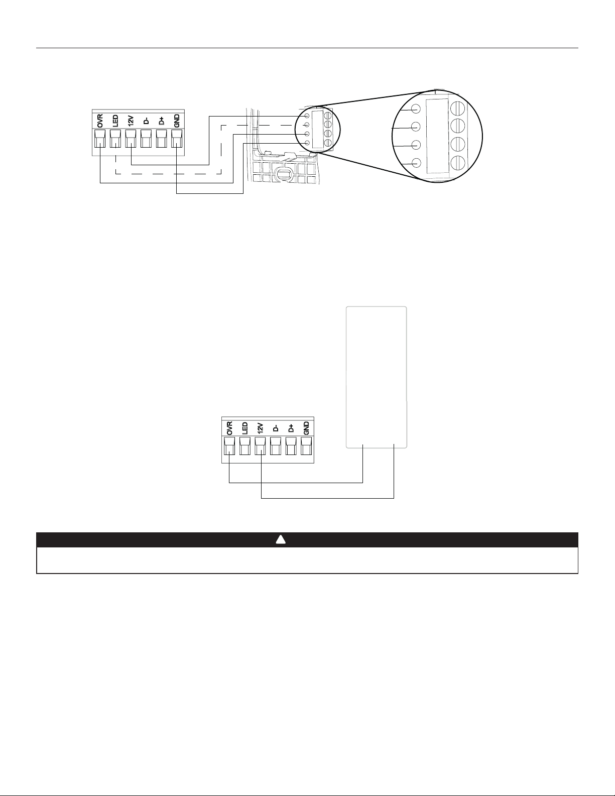
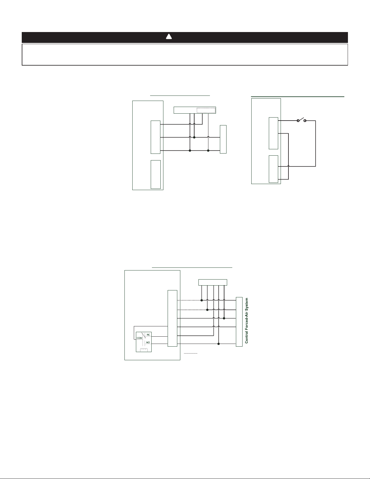
3.2 ELECTRICAL CONNECTION TO OPTIONAL AUXILIARY WALL CONTROL
3.2.1 ELECTRICAL CONNECTION TO 20-40-60 OPTIONAL AUXILIARY WALL CONTROL
Gnd
OVR
12V
LED
V
C0243
Gnd
OVR
12V
LED
When configurating OVR option on the LCD screen, choose among these 3 configurations: BAL (the unit remains balanced while
providing maximum airflow), PER (the unit is slightly unbalanced since the distribution motor is in MAX speed while allowing maximum
exhaust ventilation) and DIS (the unit is unbalanced since air distribution is constant despite a higher need in exhaust ventilation).
NOTE : The auxiliary wall control can be used with a 3-wire connection by removing the LED signals. This optional wiring will not allow an
installation with more than 1 auxiliary wall control to properly synchronize their LEDs on an event requested from a peer. Only the
auxiliary wall control having requested the timer event will have the LEDs updated accordingly.
3.2.2 ELECTRICAL CONNECTION TO DRY CONTACT OPTIONAL AUXILIARY WALL CONTROL (E.G. CRANK TIMER)
Crank Timer
or
Any Dry Contact
12VOVR
VC0256
A miswiring that sends a 24 VAC signal to the 6-position terminal block (OVR, LED, 12V, D-, D+, GND) could permanently damage the
control circuit. Verify carefully wire connections before powering-up the unit.
WARNING
!
14
3.3.2 UNIT INTERCONNECTION WITH CENTRAL FORCED-AIR SYSTEM (R/C/G/GF)
These connections must be done if you want the unit to force the central forced-air system blower operation when ventilating (refer to
solid lines in above diagram).
NOTE : These connections are required for installation configuration T-4. Refer to section 2.2 for more details.
3.3.3 SYNCHRONIZATION WITH CENTRAL FORCED-AIR SYSTEM FUNCTION
The Virtuo technology allows synchronizing the unit operation with the central forced-air system operating time. It prevents unnecessary
central forced-air system operating time while providing a better air distribution.
To use this function, W and Y connections must be added to R and C connections to inform the unit that the central forced-air system is
running (refer to dotted lines in above diagram).
Air Exchanger PCB
Terminal Blocks
Y
W
C
G
R
Y W G R C
Central Forced-Air System Thermostat
Wiring Options with Central Forced-Air System
Vent
Y
W
C
Gf
G
R
J13
Internal
Logic
Optional Wiring for Synchronization
Never connect a 120-volt AC circuit to the terminals of the central forced-air system interlock (standard wiring). Only use the low voltage
class 2 circuit of the central forced-air system blower control. The unit is designed for low voltages only. Connecting the unit on 120-volt
circuit would damage it instantly.
WARNING
!
3.3 CONNECTION TO THE CENTRAL FORCED-AIR SYSTEM
3.3.1 UNIT OPERATION USING A DRY CONTACT CONNECTION
This unit can be controlled by any dry contact connection such as the thermostat equipped with an optional ventilation output.
Y
W
C
G
R
Y W G R C Acc+ Acc-
Central Forced-Air System Thermostat
Central Forced-Air System
Wiring for Dry Contact Connection
1
1- External switch or any Dry-contact can be used to
activate Vent input if not available on the Thermostat
Air Exchanger
Terminal Blocks
Alternate Wiring for Dry Contact Independent Installation
Vent
Y
W
C
Gf
G
R
J13
OVR
LED
12V
D-
D+
GND
J9
External Switch or any
alternate Dry-Contact
Air Exchanger
Terminal Blocks
Vent
Y
W
C
Gf
G
R
J13
OVR
LED
12V
D-
D+
GND
J9
Note : Synchronization with a central forced-air system
with W and Y is not available with this configuration.
1 - External switch or any dry contact can be used to activate vent input if not
available on the thermostat. Some thermostats offer a single wire 24VAC output
for accessory ventilation. It can be directly connected to vent input and therefore
the Acc- / R connection is not required.
Once wired, unit will toggle between the
Standby mode when contact is opened and
the selected mode when contact is closed.
Choose among these 4 configurations:
minimum (unit operating in MIN speed),
intermittent (unit operating in MIN speed
20 min/hr then as per INT configuration
selection for 40 min), auto* (unit operating
according to outdoor temperature) and
maximum (unit operating in MAX speed)
in DRY option on the LCD screen when the
VENT contact is activated. Refer to section 5
for more details.
* In auto mode, the unit will operate as
follows:
• Less than -13°F = 10 min/hr
• -13°F to 19°F = 20 min/hr
• 19°F to 50°F = 40 min/hr
• 50°F to 77°F = MIN speed
• 77°F to 82°F = 30 min/hr
• 82°F to 91°F = 20 min/hr
• Above 91°F = 10 min/hr
NOTE : This dry contact option will override the main wall control so we do not recommend
the use of a wall control with this type of connection.
NOTE : Following ducting installation configuration and temperature conditions, it may be
necessary for the unit to operate continuously. Refer to section 2.2 for more details.
Loading page 15...
Loading page 16...
Loading page 17...
Loading page 18...
Loading page 19...
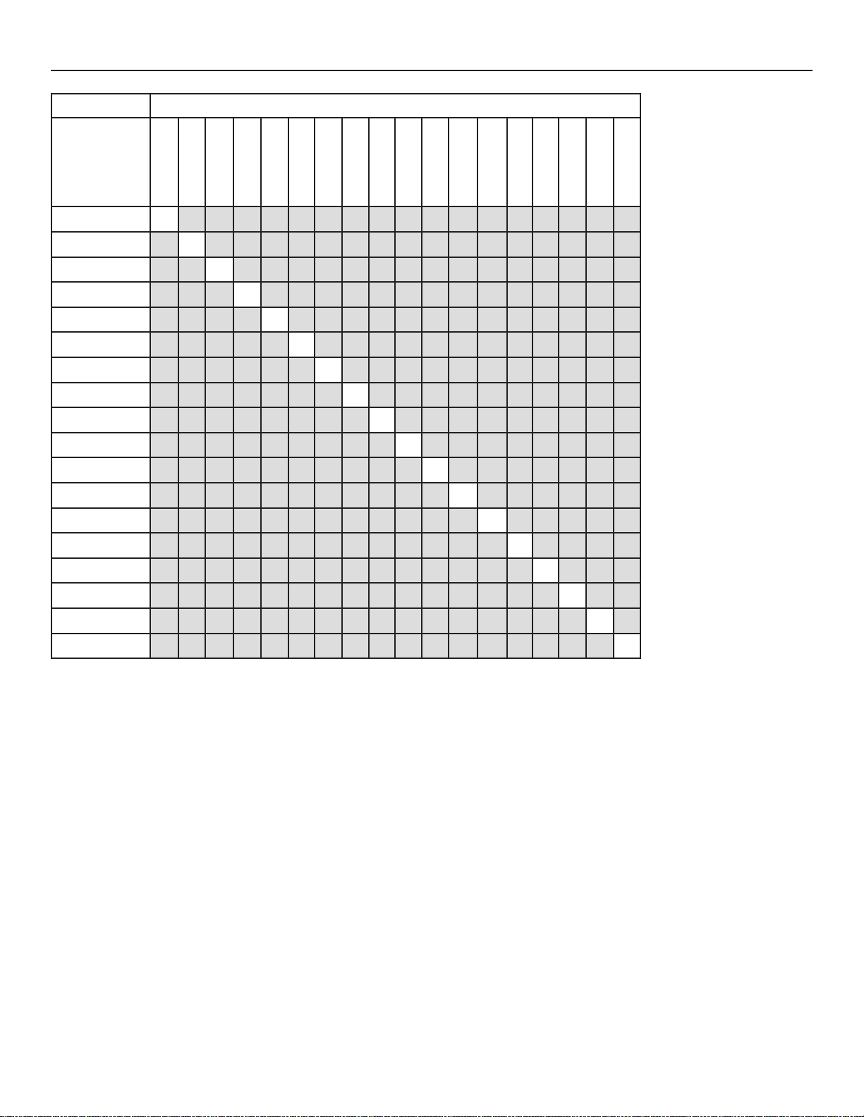
20
VENTILATION UNIT MODEL
ELECTRONIC
ASSEMBLY PART
NUMBER
SV66144-01 X
SV66144-02 X
SV66144-03 X
SV66144-04 X
SV66144-05 X
SV66144-06 X
SV66144-07 X
SV66144-08 X
SV66144-09 X
SV66144-10 X
SV66144-11 X
SV66144-12 X
SV66144-13 X
SV66144-14 X
SV66144-15 X
SV66144-16 X
SV66144-17 X
SV66144-18 X
B110H65RS
B110H65RT
B130H65RS
B130H65RT
B160H65RS
B160H65RT
B150H75NS
B150H75NT
B160H75RS
B160H75RT
B130E65RS
B130E65RT
B160E65RS
B160E65RT
B150E75NS
B150E75NT
B160E75RS
B160E75RT
7. SERVICE PARTS (CONT’D)
Loading page 21...
Loading page 22...
Loading page 23...
Loading page 24...
Loading page 25...
Loading page 26...
Loading page 27...
Loading page 28...
Loading page 29...
Loading page 30...
Loading page 31...
Loading page 32...
Loading page 33...
Loading page 34...
Loading page 35...
Loading page 36...
11
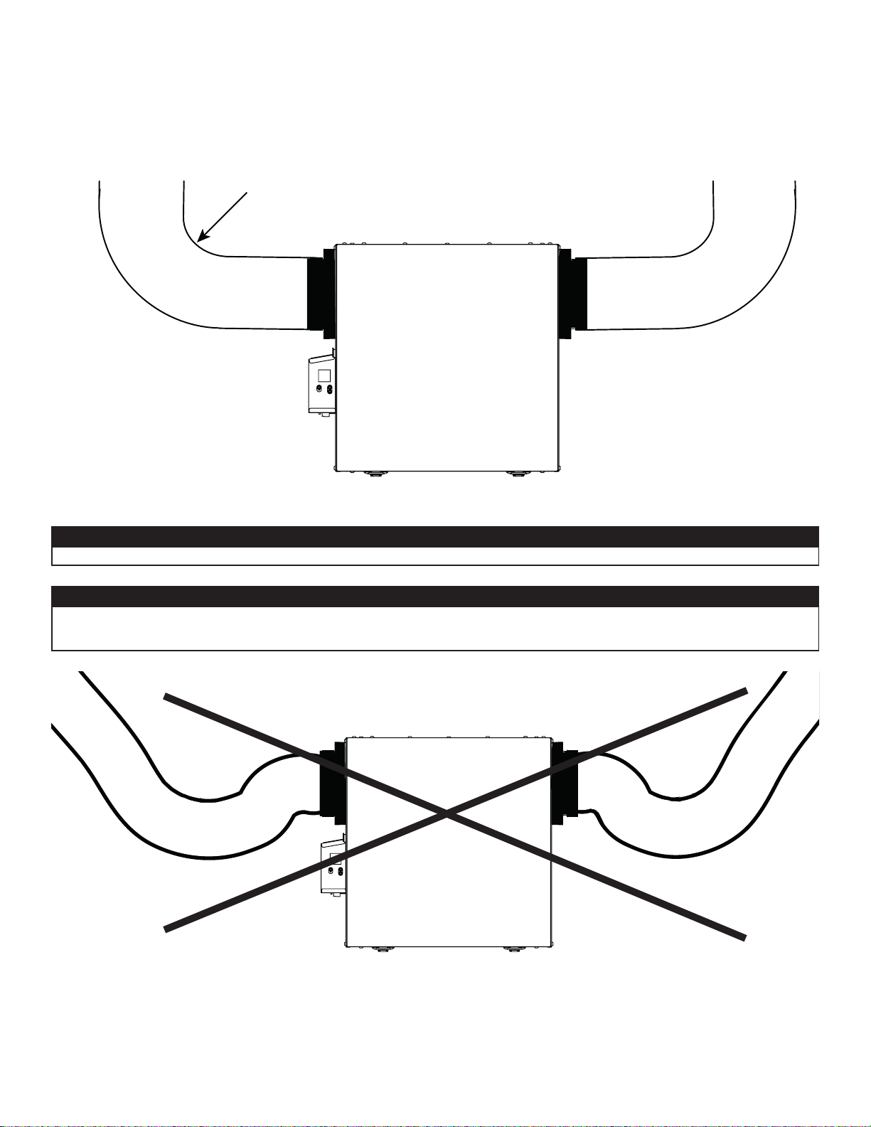
2.6.1 CONEXIÓN DE LOS CONDUCTOS
VD0489
INSTALACIÓN CORRECTA
VD0490
INSTALACIÓN INCORRECTA
Los conductos aislados deben tener el mismo diámetro que los puertos para asegurar un drenaje adecuado del agua que se pueda
acumular en los conductos.
PRECAUCIÓN
Los conductos no deben estar demasiado aplastados. De lo contrario, la precisión de los flujos de aire será afectada.
PRECAUCIÓN
IMPORTANTE: Asegúrese de conectar los conductos como se ilustra a continuación para obtener una lectura precisa de los flujos de
aire. Una instalación correcta también permitirá un drenaje adecuado del agua que se pueda acumular en los conductos.
R = 3 pulg. mínimo
NOTA: Instalar los conductos lo más recto posible, reducir el número de codos y diseños y instalar los conductos conforme al
Manual D de ACCA.
Loading page 38...
Loading page 39...
Loading page 40...
Loading page 41...
Loading page 42...
Loading page 43...
Loading page 44...
Loading page 45...
Loading page 46...
Loading page 47...
Loading page 48...
Loading page 49...
Loading page 50...
Loading page 51...
Loading page 52...