Loading ...
Loading ...
Loading ...
28
The Remote Control TRIM and LEVEL UP / DOWN-
Push-buttons may also be used. Approximately 10
seconds after Trim Function Selection and/or adjust-
ments have stopped, the C12000 will switch the Trim
Mode Off.
Adjust
The Front Panel ADJUST Control is used to make
changes to the currently selected TRIM FUNCTION.
HXD
Press the the Front Panel HXD Push-button to activate
or de-activate the HXD Circuitry. Refer to “HEAD-
PHONE HXD SELECTION” on this page for addi-
tional information.
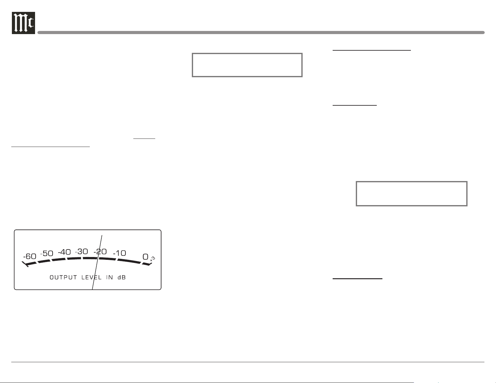
Output Meters
The C12000 Preamplifier Output Meters indicate the
Output Level in Decibels (dB) available at the MAIN,
OUTPUT 1 and OUTPUT 2 Connectors/Jacks to drive
Power Amplifiers. Refer to figure 73. The Meters are
calibrated in dB (decibels) and respond to all the peaks
contained in the musical information. A meter reading
of 0dB indicates the unit is delivering its rated output.
Figure 73
Passthru
The C12000 will automatically turn On and switch to
the previously setup Passthru Input when the McIn-
tosh A/V Processor or Multichannel Surround Decod-
er is turned-on. The Audio Preamplier Front Panel
Alphanumeric Display will indicate “PASSTHRU”.
Refer to gure 74.
Figure 74
PASSTHRU
The Front Panel Controls and Push-buttons are deac-
tived when in the Passthru Mode.
Headphones Jack
Connect a pair of dynamic headphones to the Head-
phones Jack with a 1/4” (0.635cm) stereo phone type
plug for private listening. The default setting is for the
OUTPUT 1 and OUTPUT 2 Power Amplifier Output
Connections to automatically mute, when headphones
are connected to the C12000 Front Panel Jack.
How To Make a Recording
1. Select the desired signal source you wish to record
by using the Front Panel INPUT Control or us-
ing the INPUT UP / DOWN Push-button on the
Remote Control.
2. Adjust the record level using the recorder level con-
trol and proceed with the recording process.
3. Listen to the playback of the program source just
recorded by selecting the Input Source connected to
the recorder component output.
Reset of Microprocessors
In the unlikely event the controls of the unit stop func-
tioning, the microprocessors can be reset by perform-
ing the following:
1. Press and hold in the STANDBY/ON Push-button
until the LED above the STANDBY/ON Push-
button illumination is extinguished. Then release
the STANDBY/ON Push-button.
2. To switch the C12000 back On press the STAND-
BY/ON Push-button.
Note: This can be performed with the C12000 On or in
the Standby Mode.
PHONO ADJUSTMENTS
When either the Phono 1 or Phono 2 Input is selected,
the following additional Trim Functions become avail-
able when adjusting the TRIM Control. Use the docu-
mentation for your turntable(s) attached to these inputs
to find the best settings and match them accordingly.
RESISTANCE
Change the Resistance Load Setting for a selected
Phono Cartridge (Phono 1 in this example) by per-
forming the following Steps:
1. Select the Phono 1 Input Source.
2. Rotate the Front Panel TRIM Control (TRIM) or
press the t and u Push-buttons on the Remote
Control to select “Phono 1 RES, 47kΩ” as indicat-
ed on the Front Panel Information Display. Refer to
figure 75.
3. Rotate the ADJUST Control to select desired Resis-
tance. The available settings are: 25Ω, 50Ω, 100Ω,
200Ω, 400Ω, 1KΩ, and 47kΩ.
After approximately 10 seconds the Information
Display returns to indicate the Source Selection and
Settings.
CAPACITANCE
Change the Capacitance Load Setting for a selected
Phono Cartridge (Phono 1 in this example) by per-
forming the following Steps:
1. Select the Phono 1 Input Source.
2. Rotate the Front Panel TRIM Control (TRIM)
or press the t and u Push-buttons on the Re-
mote Control to select “Phono 1 CAP, 100 pF” as
indicated on the Front Panel Information Display.
Refer to figure 76.
Phono 1 RES
47K Ω
Figure 75
Loading ...
Loading ...
Loading ...