Safety • Assembly • Operation • Tips & Techniques • Maintenance • Troubleshooting • Parts Lists • Warranty
A O AL
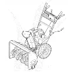
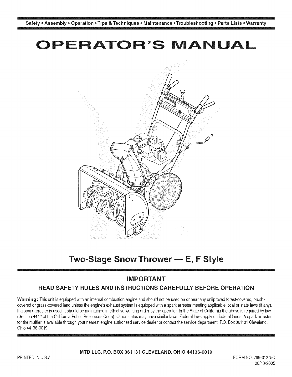
Two-Stage Snow Thrower- E, F Style
iMPORTANT
READ SAFETY RULES AND iNSTRUCTiONS CAREFULLY BEFORE OPERATION
Warning: Thisunit is equippedwithaninternalcombustionengineandshouldnot beusedon or nearany uniiprovedforest-covered,brush-
coveredor grass-coveredlandunlesstheengine'sexhaustsystemis equippedwitha sparkarrestermeetingapplicablelocalor statelaws(if any).
If a sparkarresteris used,it shouldbemaintainedineffectiveworkingorderby the operator.In theStateof Californiathe aboveis requiredbylaw
(Section4442of the CaliforniaPublicResourcesCode).Otherstatesmayhavesimilarlaws.Federallawsapplyonfederallands.A sparkarrester
for the muffleris availablethroughyour nearestengineauthorizedservicedealeror contactthe servicedepartment,RO.Box361131Cleveland,
Ohio44136-0019.
PRINTEDIN U.S.A
MTD LLC, P.O. BOX 361131 CLEVELAND, OHIO 44136-0019
FORMNO. 769-01275C
06/13/2005
This Operator's Manual is an important part of your new snow thrower, it will help you assemble,
prepare and maintain the unit for best performance. Please read and understand what it says.
Table of Contents
Safety Labels ...................................................... 3
Safe Operation Practices ................................... 4
Setting Up Your Snow Thrower .......................... 6
Operating Your Snow Thrower ........................... 8
MakingAdjustments ......................................... 12
Maintaining Your Snow Thrower ...................... 14
Off-SeasonStorage ........................................... 18
Trouble- Shooting ............................................. 19
illustrated Parts List ......................................... 20
Warranty ............................................ Back Cover
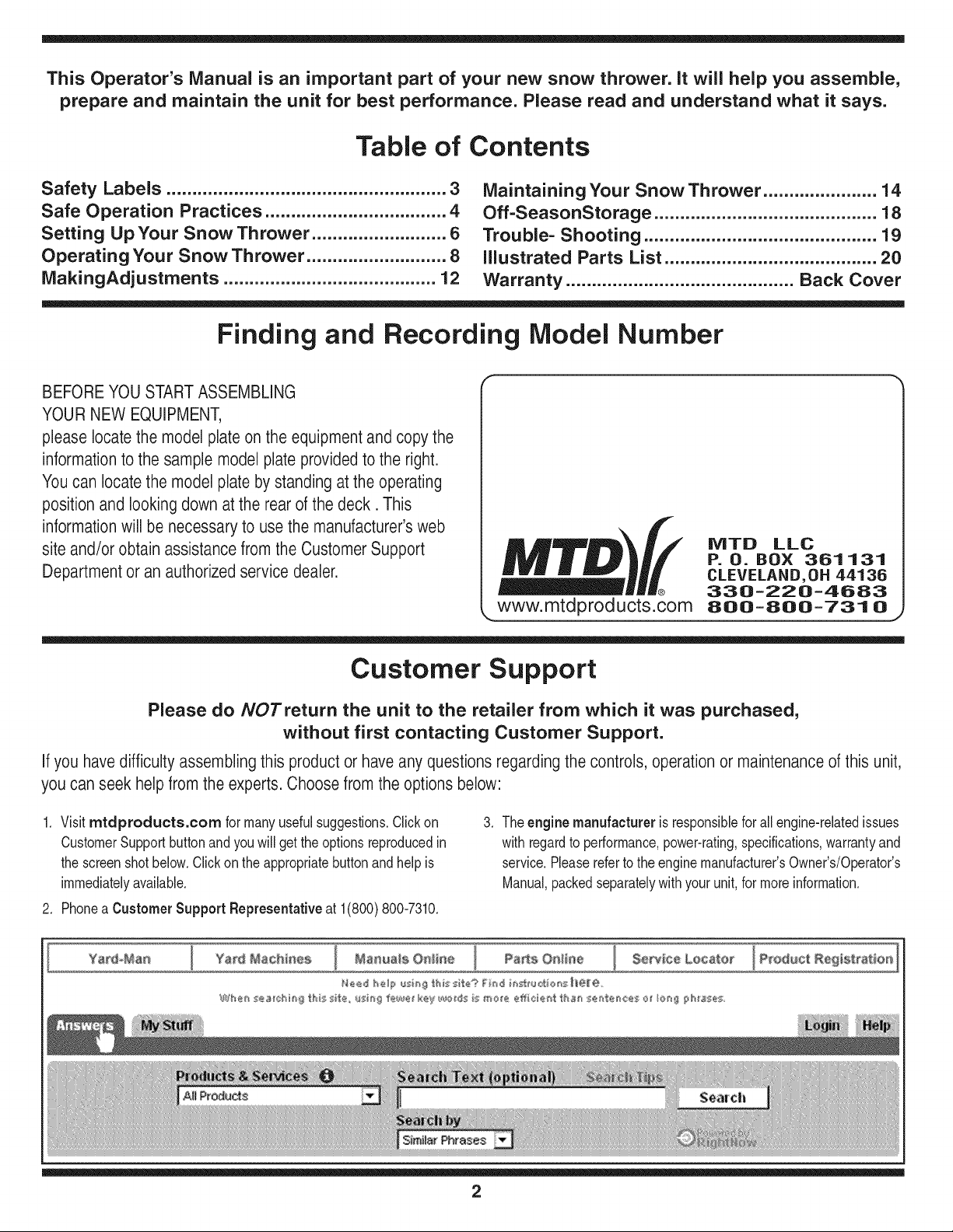
Finding and Recording Model Number
BEFOREYOU STARTASSEMBLING
YOUR NEW EQUIPMENT,
please locatethe model plate on the equipment and copy the
information to the sample model plate provided to the right.
Youcan locate the model plate by standing at the operating
position and looking down at the rear of the deck. This
information will be necessary to use the manufacturer's web
site and/or obtain assistancefrom the Customer Support
Department or an authorized service dealer.
IViTD LLC
P. O. BOX 361131
CLEVELAND,OH 44136
330-220-4683
www.mtdproducts.com_ 8oo=8oo=731 o
J
Customer Support
Please do/VOTreturn the unit to the retailer from which it was purchased,
without first contacting Customer Support.
If you have difficulty assembling this product or have any questions regardingthe controls, operationor maintenanceof this unit,
you can seek help from the experts. Choose from the options below:
1. Visitmtdproducts.com for manyusefulsuggestions.Clickon
CustomerSupportbutton and youwill get the optionsreproducedin
the screenshotbelow.Clickonthe appropriatebuttonandhelpis
immediatelyavailabb.
2. Phonea Customer Support Representative at 1(800)800-7310.
.
Theenginemanufacturer is responsiblefor allengine-relatedissues
with regardto performance,power-rating,specifications,warrantyand
service.Pleasereferto theenginemanufacturer'sOwner's/Operator's
Manual,packedseparatelywithyourunit,for moreinformation.
Ya_d_Man
Yard Machi_ea Maltreats OHHne Pa_50eHne $e_ce Locater
2
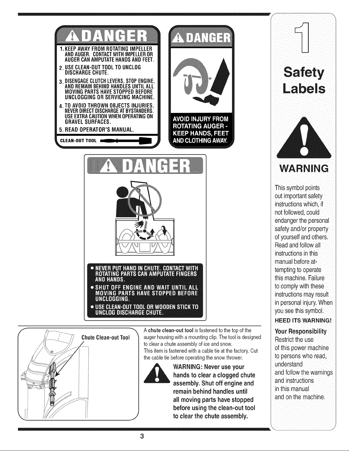
1. KEEPAWAYFROMROTATINGIMPELLER
ANDAUGER.CONTACTWITHIMPELLEROR
AUGERCANAMPUTATEHANDSANDFEET.
,
3.
,
USECLEAN-OUTTOOLTOUNCLOG
DISCHARGECHUTE.
DISENGAGECLUTCHLEVERS,STOPENGINE,
ANDREMAINBEHINDHANDLESUNTILALL
MOVINGPARTSHAVESTOPPEDBEFORE
UNCLOGGINGORSERVICINGMACHINE.
TOAVOIDTHROWNOBJECTSINJURIES,
NEVERDIRECTDISCHARGEATBYSTANDERS.
USEEXTRACAUTIONWHENOPERATINGON
GRAVELSURFACES.
5. READOPERATOR'SMANUAL.
Achuteclean-outtool is fastenedto the top of the
augerhousingwith a mountingclip. Thetool is designed
to cleara chuteassemblyof ice andsnow.
Thisitemis fastenedwith a cabletie at the factory.Cut
the cabletie beforeoperatingthe snowthrower.
_ ARNING: Never use your
hands to clear a clogged chute
assembly. Shut off engine and
remain behind handles until
all moving parts have stopped
before using the clean-out tool
to clear the chute assembly.
3
iil _I ii_ _ i _iii_!i _ _ii_ ii
WARNING
This symbol points
out importantsafety
instructionswhich, if
not followed,could
endangerthe personal
safety and/or property
of yourselfand others.
Readand follow all
instructionsinthis
manualbeforeat-
temptingto operate
this machine. Failure
to complywith these
instructionsmay result
in personalinjury.When
you see this symbol.
HEED ITS WARNING!
Your Responsibility
Restrictthe use
of this power machine
to persons who read,
understand
and follow the warnings
and instructions
in this manual
and onthe machine.
WARNING
This symbol points
out importantsafety
instructionswhich, if
notfollowed,could
endangerthe personal
i safety and/or property
I ofyourselfand others.
Readand follow all
instructionsinthis
manualbeforeat-
temptingto operate
i this machine. Failure
I to comply withthese
instructionsmay result
i in personalinjury.When
you see this symbol.
i HEED ITS WARNING!
Your Responsibility
Restrictthe use
of this power machine
to personswho read,
_ understand
ano follow the warnings
and instructions
inthis manual
and on the machine.
WARNING: Engine Exhaust, some of its constituents, and certain vehicle compo-
nents contain or emit chemicals knownto State of Californiato cause cancer and
birth defects or other reproductiveharm.
DANGER: This machine was built to be operated according to the rules for safe operation in this
manual. As with any type of power equipment, carelessness or error on the part of the operator can
result in serious injury. This machine is capable of amputating hands and feet and throwing objects.
Failureto observe the followingsafety instructionscould result in serious injury or death.
Training
1. Read,understand,andfollowall instructionsonthe 1.
machineandin the manual(s)beforeattemptingto
assembleand operate.Keepthis manualina safe placefor
futureandregularreferenceandfor orderingreplacement
parts. 2.
2. Be familiarwithall controlsandtheir properoperation.
Knowhowto stopthe machineanddisengagethem quickly.
3. Neverallow childrenunder14 yearsoldto operatethis
machine.Children14yearsold andovershouldread and
understandtheoperationinstructionsand safetyrulesin 3.
this manualand shouldbe trainedand supervisedbya
parent.
4. Neverallow adultsto operatethis machinewithoutproper
instruction.
5. Thrownobjectscan causeserious personalinjury.Plan 4.
yoursnow-throwingpatternto avoiddischargeof material
towardroads,bystandersandthe like.
6. Keepbystanders,helpers,petsandchildrenat least 75 feet 5.
fromthe machinewhileit is in operation.Stopmachineif
anyoneentersthe area. 6.
7. Exercisecautionto avoidslippingor falling,especially 7.
whenoperatingin reverse.
8,
9.
Preparation
Thoroughlyinspectthe area wherethe equipmentis to be
used. Removeall doormats,newspapers,sleds,boards,
wiresand otherforeignobjects,whichcould be tripped over
orthrown bythe auger/impeller.
Alwayswearsafetyglasses or eyeshieldsduringoperation
andwhile performingan adjustmentorrepairto protectyour
eyes.Thrownobjectswhich ricochetcan cause serious
injuryto the eyes.
Do notoperatewithoutwearingadequatewinterouter
garments.Do not wearjewelry,long scarvesorother
looseclothing,whichcould becomeentangledin moving
parts. Wearfootwearwhich willimprovefooting on slippery
surfaces.
Usea groundedthree-wireextensioncordand receptacle
forall units withelectric startengines.
Adjustcollectorhousingheight to cleargravel orcrushed
rocksurfaces.
Disengageallcontrol leversbeforestartingthe engine.
Neverattemptto makeany adjustmentswhileengineis
running,exceptwherespecificallyrecommendedinthe
operator'smanual.
Letengine andmachineadjustto outdoortemperature
beforestartingto clearsnow.
Toavoid personalinjuryor propertydamage use extreme
care inhandling gasoline.Gasolineis extremelyflammable
andthe vaporsare explosive.Serious personalinjurycan
occurwhengasolineis spilledon yourself oryour clothes,
whichcan ignite.Washyour skinand changeclothes
immediately.
a. Useonly an approvedgasolinecontainer.
b. Extinguishallcigarettes,cigars, pipes andothersources
of ignition.
c. Neverfuel machineindoors.
d. Neverremovegas cap oradd fuel whilethe engineis hot
or running.
e. Allow engineto coolat leasttwo minutesbeforerefuel-
ing.
f. Neveroverfill fuel tank. Filltankto no morethan Y2inch
below bottomoffiller neckto providespacefor fuel
expansion.
g. Replacegasolinecap andtighten securely.
h. If gasolineis spilled,wipe it off theengine and equip-
ment. Movemachineto another area.Wait 5 minutes
beforestartingthe engine.
i. Neverstorethe machineorfuel containerinside where
there is an openflame, sparkor pilot light (e.g.furnace,
waterheater,spaceheater,clothesdryeretc.).
j. Allow machineto cool at least5 minutesbeforestoring.
4
Operation
1. Donot puthands or feet near rotatingparts, inthe
auger/impellerhousingor chuteassembly.Contactwiththe
rotatingparts can amputatehands andfeet.
2. The auger/impellercontrolleveris a safetydevice.Never
bypassits operation.Doingso makesthe machineunsafe
and may causepersonalinjury.
3. The controlleversmustoperate easilyin bothdirections
and automaticallyreturnto the disengagedpositionwhen
released.
4. Neveroperate witha missingor damagedchuteassembly.
Keepall safetydevicesin place andworking.
5. Neverrunan engineindoorsor in a poorlyventilatedarea.
Engineexhaustcontainscarbonmonoxide,an odorlessand
deadly gas.
6. Donot operatemachinewhile underthe influenceof alcohol
or drugs.
7. Mufflerandengine becomehot andcan causea burn.Do
nottouch.
8. Exerciseextremecaution whenoperatingonor crossing
gravel surfaces.Stayalert for hidden hazardsor traffic.
9. Exercisecaution when changingdirectionandwhile operat-
ing on slopes.
10.Plan yoursnow-throwingpatternto avoiddischargetowards
windows,walls, cars etc. Thus, avoidingpossibleproperty
damage or personalinjury causedby a ricochet.
11.Neverdirect dischargeat children,bystandersand petsor
allow anyonein front of the machine.
12.Donot overloadmachinecapacity byattemptingto clear
snow at too fast of a rate.
13.Neveroperatethis machinewithoutgoodvisibility or light.
Alwaysbe sure of yourfooting and keepa firm holdon the
handles.Walk,neverrun.
14.Disengagepowerto the auger/impellerwhentransportingor
notin use.
15.Neveroperatemachineat hightransport speedson slippery
surfaces. Lookdownand behindand use care when
backingup.
16.Ifthe machineshouldstartto vibrate abnormally,stopthe
engine,disconnectthe sparkplug wire and groundit against
the engine.Inspectthoroughlyfor damage.Repairany
damage beforestartingandoperating.
17.Disengageallcontrol leversandstopengine beforeyou
leavethe operatingposition (behindthe handles).Wait
untilthe auger/impellercomesto a completestop before
uncloggingthe chuteassembly,makingany adjustments,or
inspections.
18.Neverputyourhand in the dischargeor collectoropenings.
Alwaysuse the clean-outtoolprovidedto unclogthe dis-
charge opening.Donot unclogchuteassemblywhileengine
is running.Shut off engine and remainbehindhandlesuntil
all movingparts havestoppedbefore unclogging.
19.Useonly attachmentsandaccessoriesapprovedbythe
manufacturer(e.g.wheelweights,tire chains,cabs etc.).
20. If situationsoccurwhich are not coveredin this manual,
use careand goodjudgment.Contactyourdealeror call
(800) 800-7310for assistanceand the nameof your nearest
servicing dealer..
Maintenance & Storage
1. Nevertamper withsafetydevices.Checktheir proper
operationregularly.Referto the maintenanceandadjust-
mentsectionsof this manual.
2. Beforecleaning,repairing,or inspectingmachinedisen-
gageall controlleversandstop the engine.Wait untilthe
auger/impellercometo a completestop. Disconnectthe
sparkplugwire and groundagainstthe engineto prevent
unintendedstarting.
3. Checkbolts and screwsfor propertightness at frequent
intervalsto keepthe machinein safeworkingcondition.
Also,visually inspectmachinefor any damage.
4. Do notchangethe enginegovernorsettingor over-speed
theengine.The governorcontrols themaximumsafe
operatingspeed of theengine.
5. Snowthrowershaveplatesand skidshoesare subjectto
wearanddamage. For yoursafetyprotection,frequently
check all componentsand replacewith originalequipment
manufacturer's(OEM) parts only."Use of partswhich do
notmeetthe original equipmentspecificationsmayleadto
improperperformanceandcompromisesafety!"
6. Checkcontrols periodicallyto verify theyengageand
disengageproperlyandadjust, if necessary.Referto the
adjustmentsection inthis operator'smanualfor instructions.
7. Maintainor replacesafetyandinstructionlabels,as neces-
sary.
8. Observeproperdisposallaws andregulationsfor gas,oil,
etc. to protectthe environment.
9. Priorto storing,run machinea few minutesto clearsnow
from machineand preventfreeze up of auger/impeller.
10.Neverstorethe machineorfuel containerinside where
thereis an openflame, sparkor pilot lightsuch as a water
heater,furnace, clothesdryeretc.
11.Alwaysreferto theoperator'smanualfor properinstructions
on off-seasonstorage.
Do not modify engine
Toavoidseriousinjuryor death,do not modifyengine inany
way.Tamperingwiththe governorsettingcan leadto a runaway
engineandcauseit to operateat unsafespeeds.Nevertamper
withfactorysettingof enginegovernor.
Notice regarding Emissions
Engineswhichare certifiedto complywithCaliforniaandfederal
EPAemissionregulationsfor SORE(SmallOff RoadEquipment)
arecertifiedto operateon regularunleadedgasoline,and may
includethefollowingemissioncontrolsystems:EngineModifica-
tion (EM)andThreeWayCatalyst(TWO)if so equipped.
Your Responsibility
Restrictthe useof this powermachineto personswho read,un-
derstandand followthe warningsand instructionsin this manual
andon the machine.
5
Operation
WARNING
This symbol points
out important safety
instructions, which if
not followed, could
endangerthe personal
safety and/or property
of yourselfand others.
Readand follow all
instructions inthis man-
ual before attempting to
operate this machine.
Failureto comply with
these instructionsmay
result in personal injury.
When you see this
symbol.
HEED IT'S WARNING!
Your Responsibility
Restrictthe use
of this power machine
to persons who read.
understand
and follow the warnings
and instructions
in this manua
and on the machine.
NOTE:Referenceto right
i and left side of the machine
areobservedfromthe
operatingposition.
NOTE:This Operator's
Manualcoversseveral
models.Snowthrower
featuresvaryby model.Not
allfeaturesdiscussedin
thismanualare applicable
to all snowthrowermodels.
NOTE:Two replacement
i augershearpinsand bow
i tie cotterpinsare provided
, foryour convenience.Store
ina safe placeuntil
i needed.Referto Augers"
I inthe MaintenanceSection
I of this manualfor more
information.
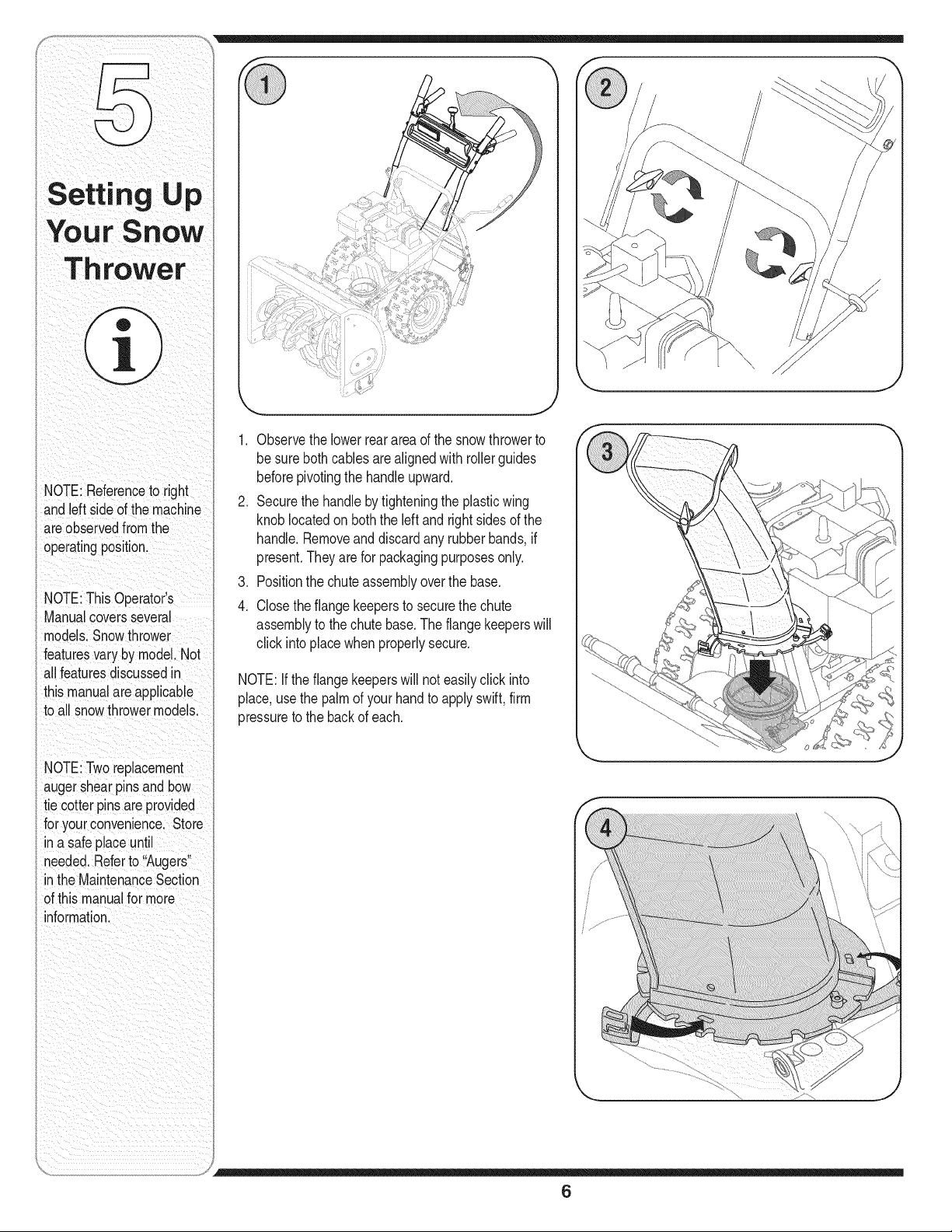
1. Observethe lowerrearareaof the snowthrowerto
besure bothcablesarealignedwith rollerguides
beforepivotingthe handleupward.
2. Securethe handleby tighteningthe plasticwing
knoblocatedon boththe leftand rightsidesof the
handle.Removeanddiscardany rubberbands,if
present.Theyare for packagingpurposesonly.
3. Positionthe chute assemblyoverthe base.
4. Closethe flangekeepersto securethe chute
assemblyto the chute base.Theflangekeeperswill
click intoplacewhenproperlysecure.
NOTE:Ifthe flangekeeperswill not easilyclick into
place,usethe palmof yourhandto applyswift,firm
pressureto the back of each.
6
u
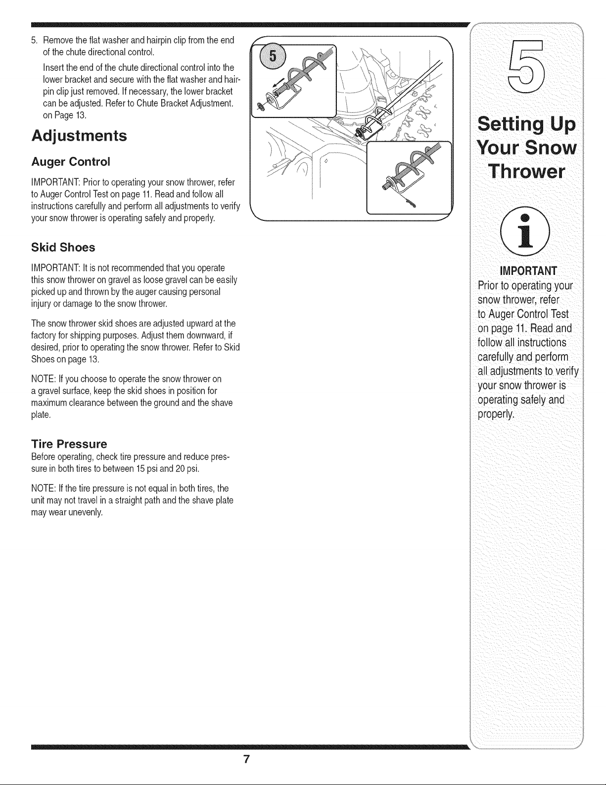
5. Removethe fiatwasherandhairpinclip from theend
of the chute directionalcontrol.
insertthe end of the chute directionalcontrolinto the
lowerbracketand securewith thefiat washerand hair-
pin clipjust removed.If necessary,the lowerbracket
can be adjusted.Referto ChuteBracketAdjustment.
on Page 13.
Adjustments
Auger Control
iMPORTANT:Priorto operatingyoursnowthrower,refer
to Auger ControlTeston page11.Readandfollowall
instructionscarefullyand performall adjustmentsto verify
your snowthrowerisoperatingsafelyand properly.
Skid Shoes
iMPORTANT:Itis not recommendedthatyou operate
this snowthroweron gravelas loosegravelcan beeasily
pickedupandthrownby the augercausingpersonal
injury or damageto the snow thrower.
The snowthrowerskid shoesare adjustedupwardat the
factoryfor shippingpurposes.Adjust themdownward,if
desired,priorto operatingthe snowthrower.Referto Skid
Shoeson page13.
NOTE:If youchooseto operatethe snowthroweron
a gravelsurface,keepthe skid shoes in positionfor
maximumclearancebetweenthe groundand the shave
plate.
Tire Pressure
Beforeoperating,checktire pressureand reducepres-
sure in bothtiresto between15psi and 20 psi.
NOTE:If thetire pressureis not equalin bothtires,the
unit may nottravelina straightpathandthe shaveplate
maywearunevenly.
Setting Up
IMPORTANT
Priorto operating your
snow thrower, refer
to Auger Control Test
on page 11.Read and
follow all instructions
carefully and perform
all adjustmentsto verify
your snow thrower is
operating safely and
properly.
7
Operating
Your S"ow
Th rower
WARNi
Read,understand,
andfo,o a, nstruc
tions andwarnings
i
on the machineand
inthismanual before
operating,
Useextremecare
whenhandling
gasoline,Gasolineis
extremely flammable
andthe vapors
explosive:Neverfuel
the machine indoors
or while the engine
is hot or running,
Extinguish cigarettesl
cigars, pipes and
othersourcesof
NOTE: Snowthrowersvary
by m0de!withregardto
featuresandcomponents:
Your snowthrowermay
NOT resemb!elin detail,
snowthrowersillustrated
infiguresthroughoutthis
manual.
i
f
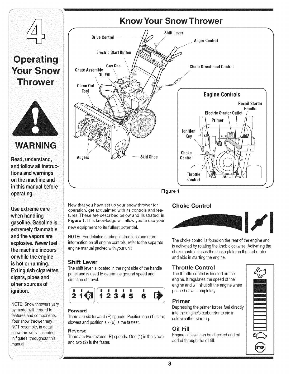
Know Your Snow Thrower
Shift Lever
DriveControl
,,_ _ AugerControl
ElectricStart Button
GasCap
ChuteAssembly
Oil Fill
\
CleanOut \
Tool
/
Augers
ignition
Key
\
Choke
Control
Control
EngineControls
RecoilStarter
Handle
Figure 1
Now that you have set up your snow thrower for
operation, get acquainted with its controls and fea-
tures. These are described below and illustrated in
Figure 1.This knowledge will allow you to use your
new equipment to its fullest potential.
NOTE: Fordetailedstartinginstructionsand more
informationonall enginecontrols,referto the separate
enginemanualpackedwith your unit
Shift Lever
The shiftleverislocatedinthe rightside of the handle
panelandis usedto determinegorundspeedand
directionof travel.
|
6
Forward
Therearesixforward(F) speeds.Positionone(1)is the
slowestandpositionsix(6) is the fastest.
Reverse
Therearetworeverse(R) speeds.One(1) is the slower
andtwo(2) is the faster.
Choke Control
I,,'1
Thechokecontrolis foundonthe rearof the engineand
isactivatedby rotatingthe knobclockwise.Activatingthe
chokecontrolclosesthe chokeplateon thecarburetor
andaids instartingthe engine.
Throttle Control
Thethrottlecontrolis locatedon the
engine.Itregulatesthe speedof the
engineandwill shut off the enginewhen
pusheddowncompletely.
Primer
Depressingthe primerforcesfuel directly
intothe engine'scarburetorto aidin
cold-weatherstarting.
Oil Fill
Engineoil levelcan be checkedand oil
addedthroughthe oil fie
©
8
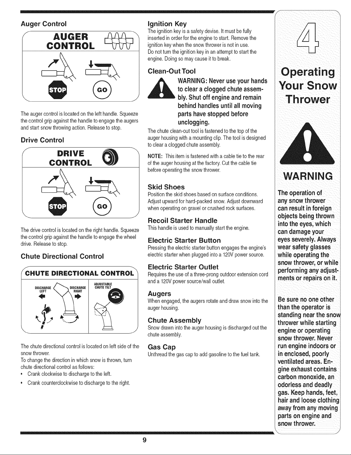
Auger Control
f
Theaugercontrolislocatedonthe left handle.Squeeze
thecontrolgripagainstthe handleto engagethe augers
andstart snowthrowingaction. Releaseto stop.
Drive Control
DRIVE
CONTROL
"x
Thedrivecontrolis locatedonthe right handle.Squeeze
thecontrolgripagainstthe handleto engagethe wheel
drive.Releaseto stop.
Chute Directional Control
CHUTE DIRECTIONAL CONTROL
DISCHARGE _'_DISCHARGE
#
ADJUSTABLE
CHUTE TiLT
J
Thechutedirectionalcontrolis locatedon left side of the
snowthrower.
Tochangethe directionin whichsnow is thrown,turn
chutedirectionalcontrolas follows:
* Crankclockwiseto dischargeto the left.
* Crankcounterclockwiseto dischargeto the right.
Ignition Key
The ignitionkeyis a safetydevise.It mustbefully
insertedin orderfor the engineto start. Removethe
ignitionkeywhenthe snowthrowerisnot inuse.
Donot turnthe ignitionkeyinan attemptto startthe
engine.Doingso maycauseit to break.
Clean-Out Tool
,_k WARNING• Never use your hands
to clear a clogged chute assem-
-- bly. Shut off engine and remain
behind handles until all moving
parts have stopped before
unclogging.
The chuteclean-outtool isfastenedto the topof the
augerhousingwith a mountingclip. Thetool isdesigned
to clear a cloggedchuteassembly.
NOTE: Thisitemis fastenedwith a cabletie to the rear
of the auger housingat the factory.Cutthe cabletie
beforeoperatingthe snowthrower.
Skid Shoes
Positionthe skid shoesbasedonsurfaceconditions.
Adjustupwardfor hard-packedsnow.Adjustdownward
whenoperatingongravelor crushed rock surfaces.
Recoil Starter Handle
Thishandleis usedto manuallystart the engine.
Electric Starter Button
Pressingtheelectricstarterbuttonengagesthe engine's
electricstarterwhenpluggedintoa 120Vpowersource.
Electric Starter Outlet
Requirestheuse of a three-prongoutdoorextensioncord
anda 120Vpowersource/wailoutlet.
Augers
Whenengaged,the augersrotateanddraw snowinto the
augerhousing.
Chute Assembly
Snowdrawnintothe augerhousingisdischargedoutthe
chuteassembly.
Gas Cap
Unthreadthe gas capto addgasolineto the fueltank.
WARNIN,3
The operation of
any snow thrower
can result in foreign
objectsbeing thrown
into the eyes; which
Candamage your
eyes severely, Always
wear safety glasses
while operating the
snow thrower, or while
performinganyadjust:
ments or repairs on it:
Be sure noone ott
than the operator is
standing,,earthesno,,
thrower while starting
engine or operating
snow thrower, Never
run engine indoors or
in enclosed, poorly
ventilated areas, En,
gine exhaust contains
carbon monoxide; an
odo, essanddeaa y
gaS;Keep hands; feet,
hairand oosec oth ng
away from any moving
parts on engine and
9
WARNING
Read, understand,
and follow all instruc-
tions and warnings
on the machine and
in this manual before
operating.
Use extreme care
when handling
gasoline. Gasoline is
extremely flammable
and the vapors are
explosive. Neverfuel
the machine indoors
or while the engine
is hot or running.
Extinguish cigarettes,
cigars, pipes and
other sources of
ignition.
if your home's
wiring system is not a
three-wire grounded
system, do not use
this electric starter
under any conditions.
if your home
electrical system
is grounded, but a
three-hole receptacle
is not available, do
not use your snow
thrower's electric
starter.
Gas & Oil Fill-Up
Servicethe enginewith gasolineandoil as instructedin
theTecurnsehEnginesmanualpackedseparatelywith
yoursnowthrower.Readinstructionscarefully.
StartingThe Engine
1. Attachsparkplugwireto sparkplug. Makecertain the
metalloopon the end of the sparkplug wire (inside
the rubberboot)is fastenedsecurelyoverthe metal
tip on the spark plug.
2. Makecertainboththe augercontroland drivecontrol
arein thedisengaged(released)position.
3. Movethrottlecontrolupto FASTposition.Insert
ignitionkeyinto slot. Makesureit snapsintoplace.
Do notattemptto turn the key.
NOTE:The enginecannotstart unlessthe key is
insertedintoignitionswitch.
Electric Starter
1. Determinethatyourhome'swiringis a three-wire
groundedsystem.Ask a licensedelectricianif you are
notcertain.
_ ARNING: The optional electric
starter is equipped with a
grounded three-wire power cord
and plug, and is designed to op-
erate on 120 volt AC household
current, it must be used with a
properly grounded three-prong
receptacle at all times to avoid
the possibility of electric shock.
Follow all instructions carefully
prior to operating the electric
starter.
If youhavea groundedthree-prongreceptacle,proceed
as follows:
1. Plugtheextensioncord intothe outletlocatedon the
engine'ssurface.Plugthe otherend of extensioncord
intoa three-prong120-volt,grounded,ACoutletina
well-ventilatedarea.
2. Rotatechokecontrol to FULLchokeposition(for a
coldenginestart).
6. Asthe enginewarms,slowlyrotatethe chokecontrol
to the OFFposition.Ifthe enginefalters,quicklyrotate
thechokecontrolbackto FULLandthen slowlyinto
theOFFpositionagain.
7. Whendisconnectingtheextensioncord, always
unplugtheendat thethree-prongwalloutletbefore
unpluggingthe oppositeend from the snowthrower.
Recoil Starter
1. Rotatechokecontrolto FULLchokeposition(cold
enginestart).
NOTE:If the engineis alreadywarm,placechokecontrol
inthe OFF positioninsteadof FULL.
2. Pushthe primertwo or threetimesfor coldengine
start,makingsureto coverventholeinthe centerof
theprimerwhenpushing.
NOTE:DO NOTuse primerto restarta warm engine
aftera short shutdown.
NOTE:Additionalprimingmay be necessaryif the
temperatureis below150Fahrenheit.
3. Graspthe recoilstarterhandleand slowlypullthe
ropeout.At the pointwhereit becomesslightlyharder
to pull the rope,slowlyallowthe ropeto recoil.
4. Pullthe starterhandlewith a firm, rapidstroke.Do not
releasethe handleand allowit to snapback.Keepa
firmholdon the starterhandleandallowit to slowly
recoil.
.
Asthe enginewarms,slowlyrotatethe chokecontrol
to the OFFposition.Ifthe enginefalters,quicklyrotate
thechokecontrolbackto the FULLpositionand then
slowlyintothe OFFpositionagain.
NOTE:Allowthe engineto warmup fora few minutes
afterstarting.The enginewill notdevelopfull poweruntil
it reachesoperatingtemperatures.
Stopping The Engine
Runenginefor a fewminutesbeforestoppingto helpdry
offany moistureon the engine.
• Tohelppreventpossiblestarterfreeze-up,proceedas
follows:
NOTE: If the engineis alreadywarm,placechokecontrol
inthe OFFpositioninsteadof FULL.
3. Pushthe primertwoor threetimesfor coldengine
start,makingsureto coverventholein thecenterof
the primerwhenpushing.
NOTE: DONOTuseprimerto restarta warm engine
aftera short shutdown.
4. Pushstarterbuttonto start engine.
5. Oncethe enginestarts,releasestarterbutton.
Electric Starter
1. Connectextensioncord to the electricstarteroutlet
onthe engine,then to 120voltAC outlet.
2. Withthe engine running,pushthe starterbuttonand
allowthe starterfor spin for severalseconds.The
noisemadebythe starteris normal.The engine's
starteris not beingharmed.
3. Whendisconnectingtheextensioncord, always
unplugtheendat thethree-prongwalloutletbefore
unpluggingthe oppositeend from the snowthrower.
10
4. Movethrottlecontrolto STOPposition.
5. Removethe ignitionkey and store in a safe place.
6. Wipeall snowandmoisturefrom theareaaroundthe
engineas wellas the area in and aroundthe drive
controlandaugercontrol.Also,engageand release
bothcontrolsseveraltimes.
Recoil Starter
1. Withenginerunning,pull starter ropewith a rapid,
continuousfull arm strokethreeor fourtimes.Pulling
the starterropewill producea loud clatteringsound,
whichis notharmfulto engine.
2. Movethrottlecontrolto STOPposition.
3. Removethe ignitionkey and store in a safe place.
4. Wipeall snowandmoisturefrom theareaaroundthe
engineas wellas the area in and aroundthe drive
controlandaugercontrol.Also,engageand release
bothcontrolsseveraltimes.
Chute Clean-Out Tool
Thechuteclean-outtool is convenientlyfastenedto the
rearof the augerhousingwitha mountingclip.Should
snowandice becomelodgedin the chuteassembly
duringoperation,proceedas followsto safelycleanthe
chuteassemblyandchuteopening:
1. Releaseboththe AugerControland the DriveControl.
2. Stopthe engineby removingthe ignitionkey.
3. Removethe clean-outtool fromthe clip which secures
it to the rearof the augerhousing.
4. Usethe shovel-shapedendof the clean-outtool to
dislodgeand scoop anysnow and icewhichhas
formedinand nearthe chute assembly.
5. Refastenthe clean-outtool to the mountingclip on the
rearof the augerhousing,reinsertthe ignitionkey and
startthe snowthrower'sengine.
6. Whilestandinginthe operator'sposition(behindthe
snowthrower),engagethe augercontrolfor a few
secondsto clearany remainingsnowand ice from the
chuteassembly.
To Engage Drive
Withthethrottlecontrolinthe Fast(rabbit)position,
moveshift leverintooneof the sixforward(F)
positionsor two reverse(R) positions.Selecta speed
appropriatefor the snowconditionsand a paceyou're
comfortablewith.
2. Squeezetheauger controlagainstthe handleand the
augerswill turn. Releaseit and the augerswill stop.
3. Squeezethedrivecontrolagainstthehandlethe snow
throwerwill move.Releaseit anddrivemotionwill
stop.
To Engage Augers
1. Toengagetheaugersandstart throwingsnow,
squeezethe augercontrolagainstthe left handle.
Releaseto stopthe augers.
Auger Control Test
Performthe followingtest beforeoperatingyour snow
throwerfor the firsttimeand at the startof eachwinter.
Checkthe adjustmentof the augercontrolas follows:
1. Whenthe auger controlis releasedandin the
disengaged"up"position,the cableshouldhavevery
littleslack.It shouldNOTbetight.
2. In a well-ventilatedarea,start the snowthrowerengine
as instructedon the previouspage.Makesurethe
throttleis setin the FASTposition.
3. Whilestandinginthe operator'sposition(behindthe
snowthrower),engagethe auger.
4. Allowtheaugerto remainengagedfor approximately
ten (10)secondsbeforereleasingtheauger control.
Repeatthis severaltimes.
5. Withthe throttlecontrolinthe FAST(rabbit)position
andtheaugercontrolin thedisengaged"up"position,
walkto thefrontof the machine.
6. Confirmthat the augerhas completelystopped
rotatingand showsNOsignsof motion.If theauger
showsANY signsof rotating,immediatelyreturnto the
operator'spositionand shutoff the engine.Waitfor
ALLmovingpartsto stopbeforere-adjustingtheauger
control.
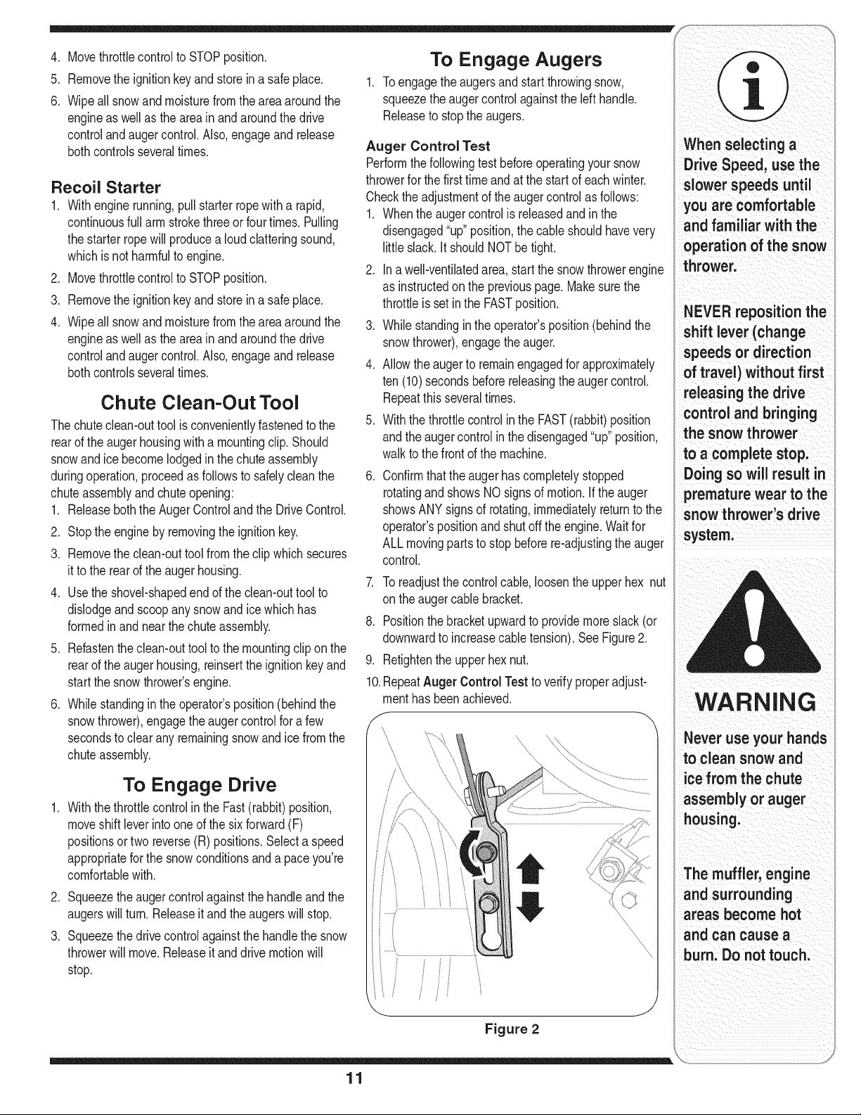
7. Toreadjustthe controlcable,loosentheupperhex nut
onthe augercable bracket.
8. Positionthe bracketupwardto providemoreslack(or
downwardto increasecabletension).SeeFigure2.
9. Retightenthe upper hexnut.
10.RepeatAuger Control Test to verify properadjust-
menthasbeenachieved.
I
Figure 2
When selecting a
Drive Speed; use the
slower speeds unt
you are comfortable
and familiar with the
operation of the snow
thrower,
NEVER reposition the
shift lever (cha nge
direction
I)without first
releasing the drive
control and bringing
snow
toacompletestop,
Doingsowillresultin
premature wear tothe
snow thrower's drive
system.
:WARNING
Neveruseyourhands
to clean snow and
ice from the chute
assembly or auger
Themuffler'engine
and surrounding
areas become hot
and can cause a
11
Mak=ng
Adjustments
WARNING
Read, understand,
and follow all instruc-
tions and warnings
on the machine and
in this manual before
operating.
Never attempt to
make any adjust-
ments while the
engine is running,
except where speci-
fied in operator's
manual.
Auger Control
Referto AugerControlTeston Page11to adjustthe
augercontrol.
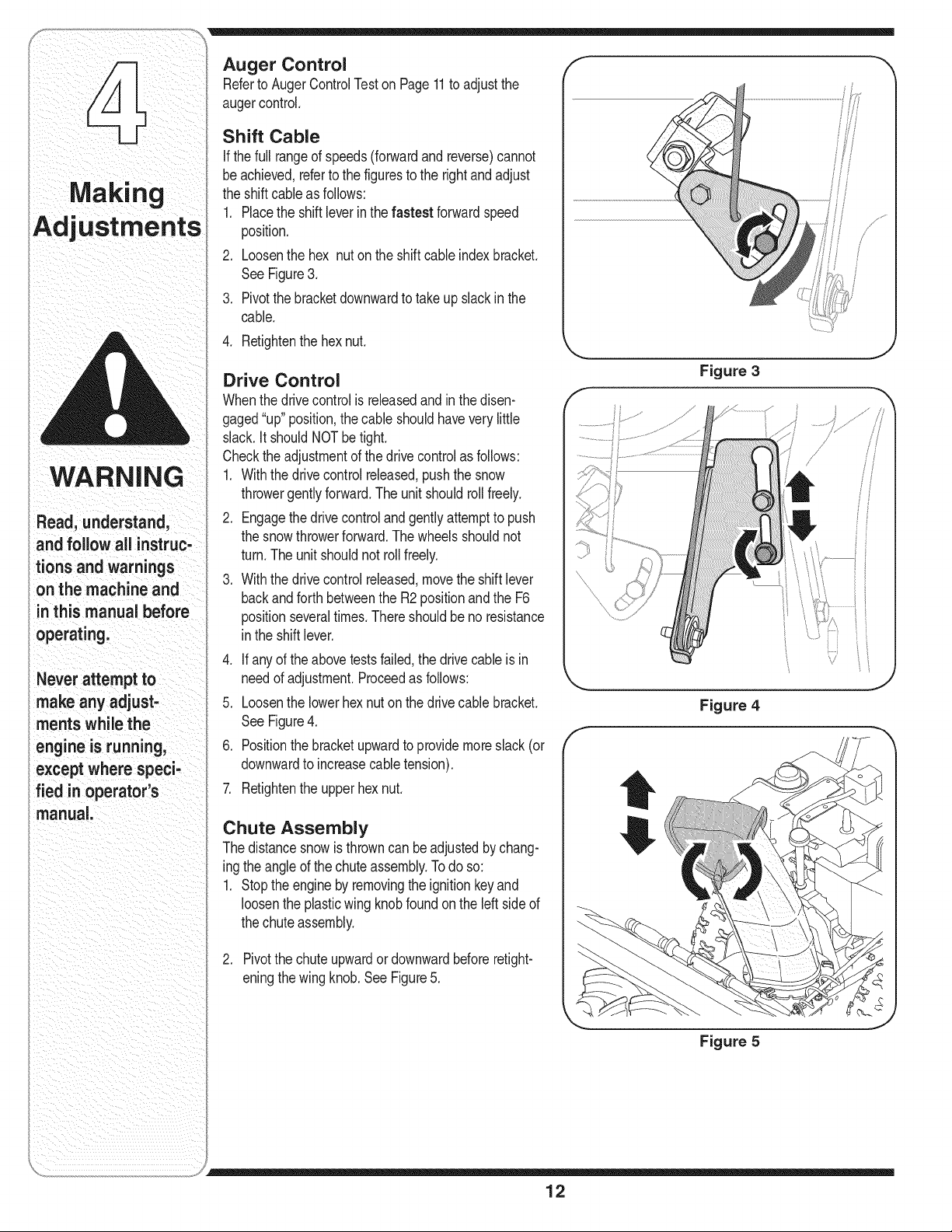
Shift Cable
If thefull rangeof speeds(forwardand reverse)cannot
beachieved,referto the figuresto the rightand adjust
the shiftcableas follows:
1. Placethe shiftleverinthe fastest forwardspeed
position.
2. Loosenthe hex nuton the shiftcable indexbracket.
SeeFigure3.
3. Pivotthe bracketdownwardto takeupslack inthe
cable.
4. Retightenthe hex nut.
Drive Control
Whenthe drivecontrolisreleasedandinthe disen-
gaged"up" position,the cable shouldhaveverylittle
slack.It shouldNOT be tight.
Checkthe adjustmentof the drivecontrolas follows:
1. Withthe drive controlreleased,pushthe snow
throwergentlyforward.The unitshouldrollfreely.
2. Engagethe drivecontroland gentlyattemptto push
the snowthrowerforward.Thewheelsshouldnot
turn.The unit shouldnotrollfreely.
3. Withthe drive controlreleased,movethe shift lever
backandforth betweenthe R2positionand the F6
positionseveraltimes.There shouldbe no resistance
inthe shiftlever.
4. If anyof the abovetests failed,the drive cableis in
needof adjustment.Proceedasfollows:
5. Loosenthe lowerhexnut onthe drivecable bracket.
SeeFigure4.
6. Positionthe bracketupwardto providemoreslack (or
downwardto increasecabletension).
7. Retightenthe upper hexnut.
Chute Assembly
Thedistancesnowisthrowncan beadjustedby chang-
ingthe angleof the chute assembly.Todo so:
1. Stopthe engineby removingthe ignitionkeyand
loosenthe plasticwing knobfound on the left sideof
thechuteassembly.
2. Pivotthe chute upwardor downwardbeforeretight-
eningthe wingknob.SeeFigure5.
f
f
Figure 3
/
Figure 4
J
fi
f
Figure 5
)
12
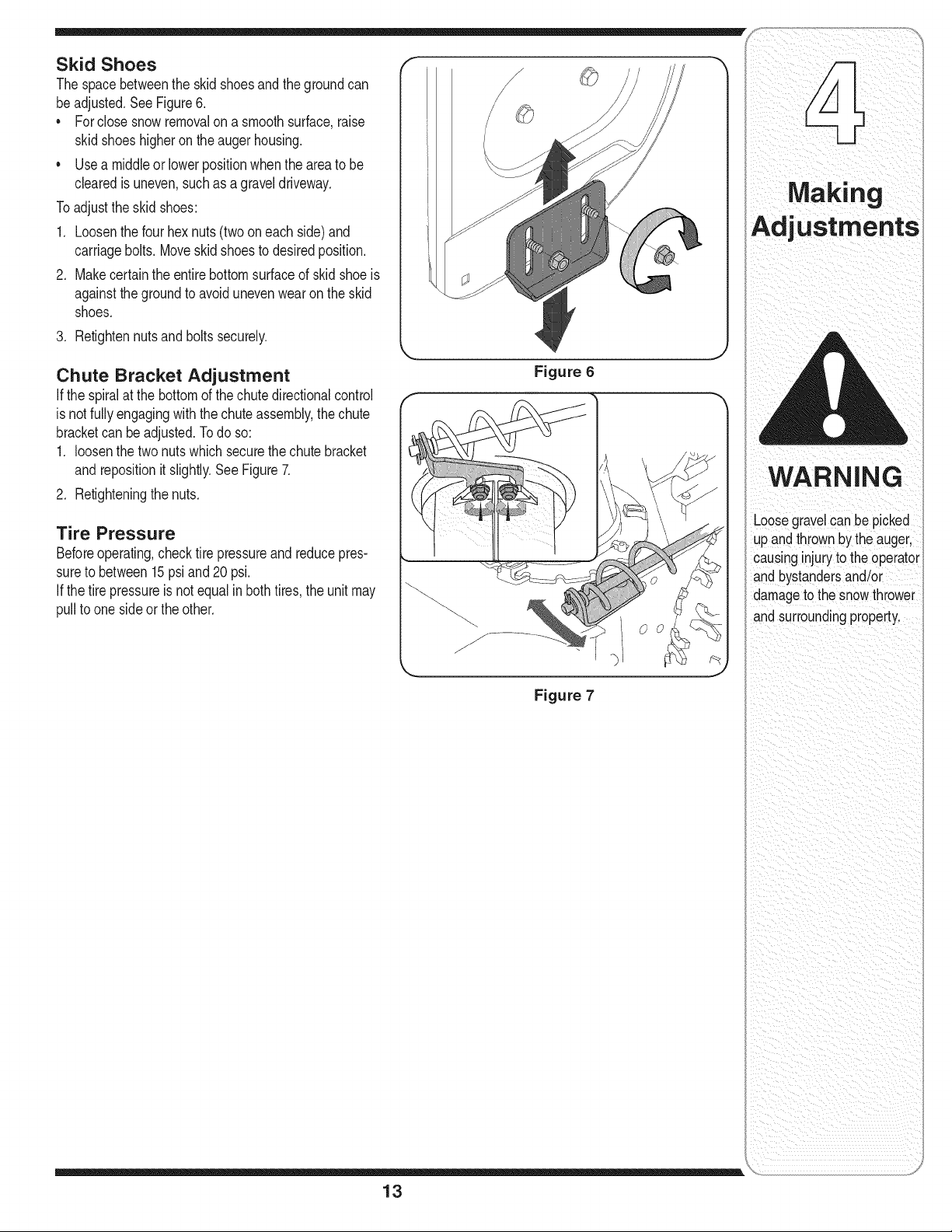
Skid Shoes
The spacebetweenthe skid shoesand the groundcan
beadjusted.See Figure6.
• Forclose snow removalon a smoothsurface,raise
skidshoeshigheron the augerhousing.
Usea middleor lowerpositionwhenthe areato be
clearedis uneven,suchas agraveldriveway.
Toadjustthe skidshoes:
1. Loosenthe four hexnuts (two on each side)and
carriagebolts. Moveskid shoesto desiredposition.
2. Makecertainthe entirebottomsurfaceof skidshoeis
againstthegroundto avoidunevenwearon the skid
shoes.
3. Retightennutsand boltssecurely.
Chute Bracket Adjustment
If the spiralat the bottomof the chutedirectionalcontrol
isnot fullyengagingwiththe chuteassembly,thechute
bracketcan be adjusted.Todo so:
1. loosenthe two nutswhich securethe chute bracket
andrepositionit slightly.See Figure7.
2. Retighteningthe nuts.
Tire Pressure
Beforeoperating,checktire pressureand reducepres-
sureto between15psiand 20psi.
If thetire pressureisnotequalinbothtires,the unit may
pullto one side or the other.
Figure 6
Figure 7
13
WARNING
Loosegravelcan be picked
up andthrown bythe auger,
causinginjuryto the operator
andbystandersand/or
damageto the snowthrower
andsurroundingproperty.
==,
Maintaining
Your Snow
Avo!do! sp!l age on
rubberfriCtionWheel
and aiuminum drive
DOnot overfillthe gear
easelDamage to the
seals could resUltl
l
Engine
Referto the separate TecumsehEnginesmanual
packedwithyour unitfor all enginemaintenance.
Lubrication
Engine
Referto the separate TecumsehEnginesmanual
packedwithyour unitfor all enginelubricationinstruc-
tions.
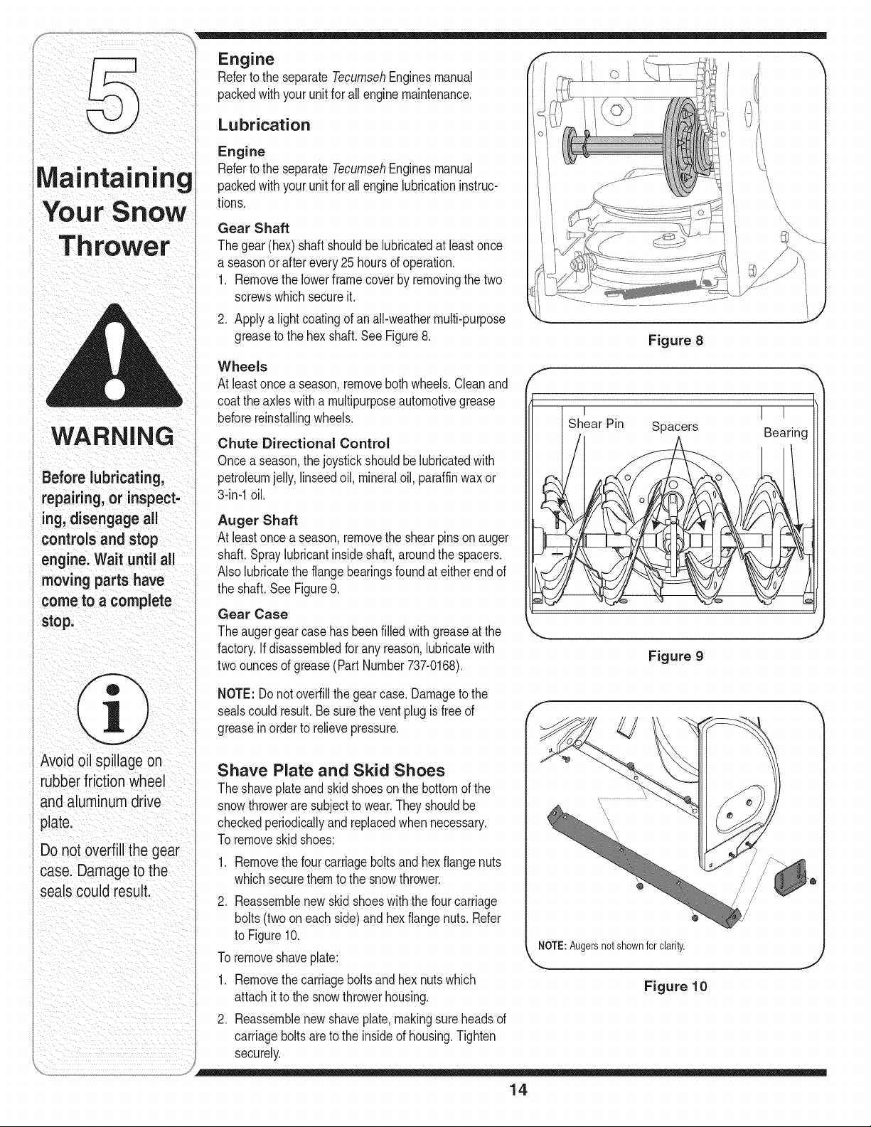
Gear Shaft
Thegear(hex) shaftshouldbelubricatedat leastonce
a seasonor after every25 hoursof operation.
1. Removethelowerframecoverby removingthe two
screwswhichsecureit.
2. Applya lightcoatingof an all-weathermulti-purpose
greaseto the hex shaft.See Figure8.
Wheels
At leastonce a season,removeboth wheels.Cleanand
coattheaxleswitha multipurposeautomotivegrease
beforereinstallingwheels.
Chute Directional Control
Oncea season,thejoystickshouldbelubricatedwith
petroleumjelly,linseedoil, mineraloil, paraffinwax or
3-in-1oil.
Auger Shaft
At leastonce a season,removethe shearpinson auger
shaft.Spraylubricantinsideshaft, aroundthe spacers.
Alsolubricatethe flangebearingsfoundat eitherendof
the shaft. See Figure9.
Gear Case
Theaugergearcasehas beenfilled with greaseat the
factory.If disassembledfor any reason,lubricatewith
twoouncesof grease(Part Number737-0168).
f
Figure 8
I
I I
Bearing
Figure 9
NOTE: Donot overfillthe gearcase. Damageto the
sealscould result.Besurethe ventplugis freeof
greasein orderto relievepressure.
Shave Plate and Skid Shoes
Theshaveplateand skidshoesonthe bottomof the
snowthroweraresubjectto wear.Theyshouldbe
checkedperiodicallyand replacedwhennecessary.
Toremoveskidshoes:
1. Removethefour carriagebolts and hexflangenuts
whichsecurethemto the snowthrower.
2. Reassemblenew skid shoeswith the fourcarriage
bolts(twooneach side)andhexflange nuts.Refer
to Figure10.
Toremoveshaveplate:
1. Removethecarriageboltsand hexnutswhich
attachit to the snowthrowerhousing.
2. Reassemblenew shaveplate,makingsureheadsof
carriagebolts are to the insideof housing.Tighten
securely.
/
/
/
/
@
NOTE:Augersnot shown forclarity,
J
Figure 10
14
m
/
/
f' i "_
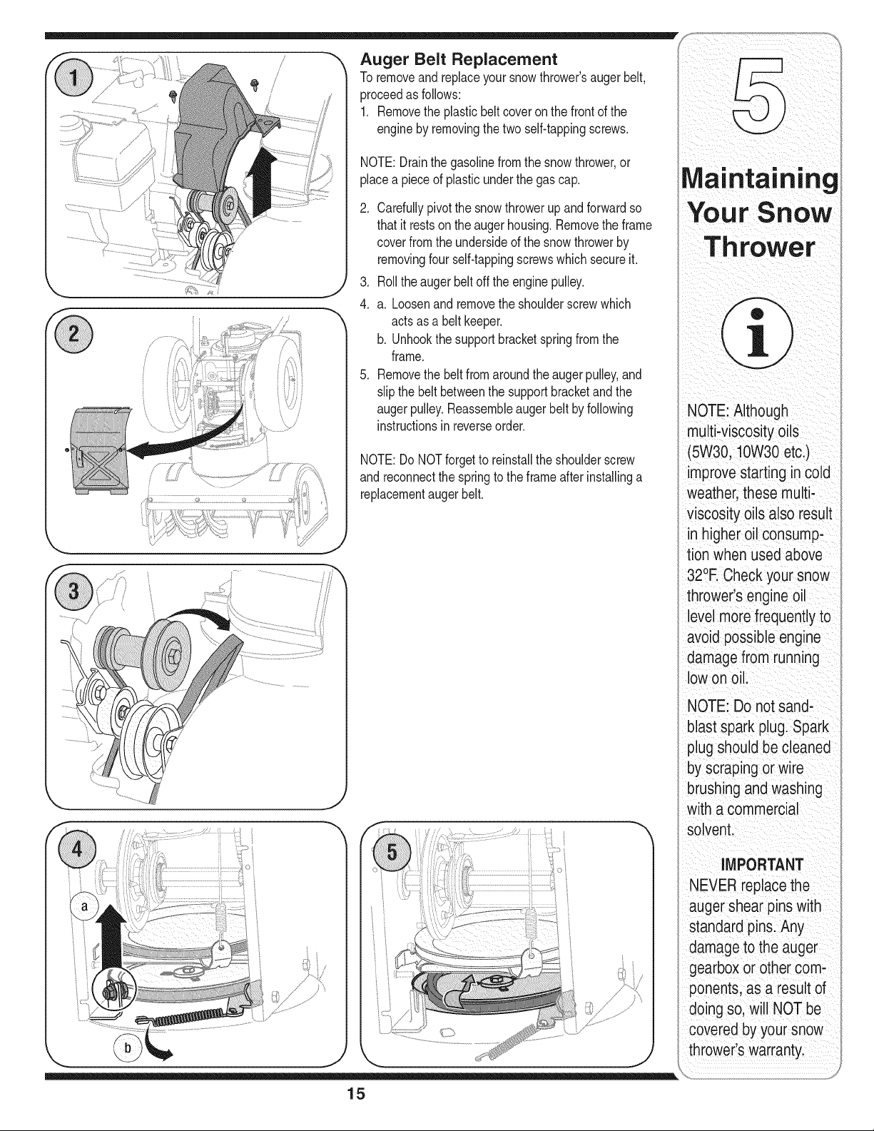
Auger Belt Replacement
To removeandreplaceyoursnow thrower'saugerbelt,
proceedas follows:
1. Removethe plasticbelt coveron the front of the
engineby removingthe two self-tappingscrews.
NOTE:Drainthe gasolinefromthe snowthrower,or
placea pieceof plasticunderthe gas cap.
.
.
4.
.
ntaining
C re,u,yp,vo,soow up so Your Snow
thatit restson the augerhousing.Removethe frame
coverfromthe undersideof the snow throwerby
removingfour self-tappingscrewswhichsecureit.
Rollthe augerbeltoff the enginepulley.
a. Loosenand removethe shoulderscrewwhich
actsas a belt keeper.
b. Unhookthesupportbracketspringfromthe
frame.
Removethe beltfromaroundtheaugerpulley,and
slipthe beltbetweenthe supportbracketand the
augerpulley.Reassembleaugerbelt by following
instructionsin reverseorder.
NOTE:Do NOTforgetto reinstallthe shoulderscrew
andreconnectthe springto the frameafterinstallinga
replacementaugerbelt.
NOTE: Although
multi;viscosity oils
(5W30, !0W30 etci)
improve starting in cold
Weather; these multi;
Viscosity oilSalso reSUlt
higher oil consump_
tion when used above
32°R C!eck your snow
thrower s engine oil
leVelmore frequently to
avoid possible engine
damage from running
loWon oil;
NOTE: Do not sand,
b astsparkp uglspark
plug should be cleaned
ioysCrapingor wire
brushing and Washing
with a commercial
solVenL
IMPORTANT
NEVERreplace the
auger shear pins With
standard pins. Any
damage to the auger
gearbox orother com,
resultof
I sol WillNOT be
CoVeredby your snow
throwerls Warrantyl
15
NEVERreplace
theaugershear
pinswithanything
otherthanOEM
PartNo.738-04124
replacementshear
pins.Anydamageto
theaugergearbox
orothercomponents
asa resultoffailing
todosowillNOTbe
coveredbyyoursnow
i thrower'swarranty.
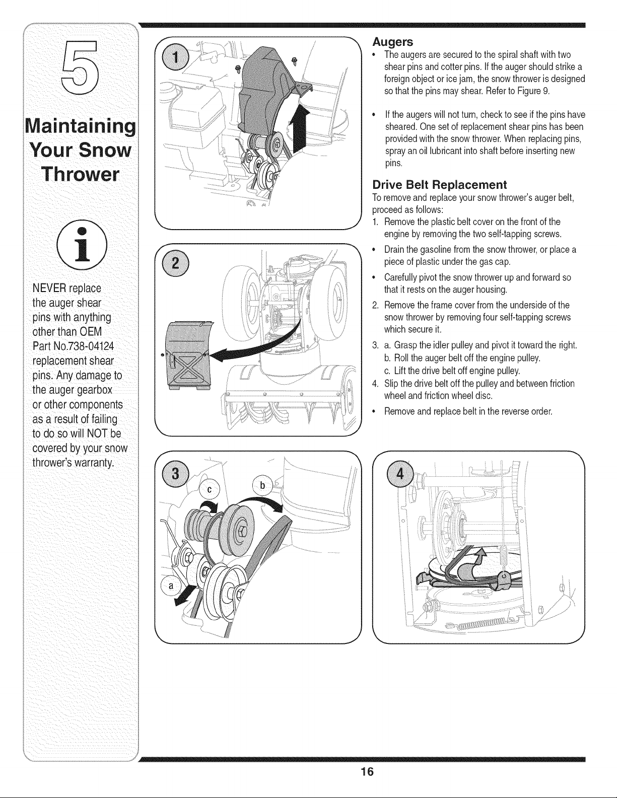
Augers
* Theaugersare securedto the spiralshaftwithtwo
shearpinsandcotterpins.If the augershouldstrikea
foreignobject or icejam,the snowthroweris designed
so that the pinsmayshear.Referto Figure9.
If theaugerswill notturn,checkto seeif the pinshave
sheared.Onesetof replacementshearpins hasbeen
providedwith the snowthrower.When replacingpins,
sprayanoil lubricantintoshaft beforeinsertingnew
pins.
Drive Belt Replacement
Toremoveand replaceyoursnowthrower'saugerbelt,
proceedas follows:
1. Removetheplasticbelt coveron thefront of the
engineby removingthe two self-tappingscrews.
* Drainthe gasolinefromthe snowthrower,or placea
pieceof plasticunderthe gas cap.
* Carefullypivotthe snowthrowerupand forwardso
thatit restson the augerhousing.
2. Removetheframecoverfromthe undersideof the
snowthrowerby removingfour self-tappingscrews
whichsecureit.
3. a. Graspthe idlerpulleyand pivot it towardthe right.
b. Rollthe augerbeltoff the enginepulley.
c. Lift the drivebelt off engine pulley.
4. Slipthe drivebeltoff the pulleyandbetweenfriction
wheelandfrictionwheeldisc.
* Removeandreplacebelt in the reverseorder.
f
J
16
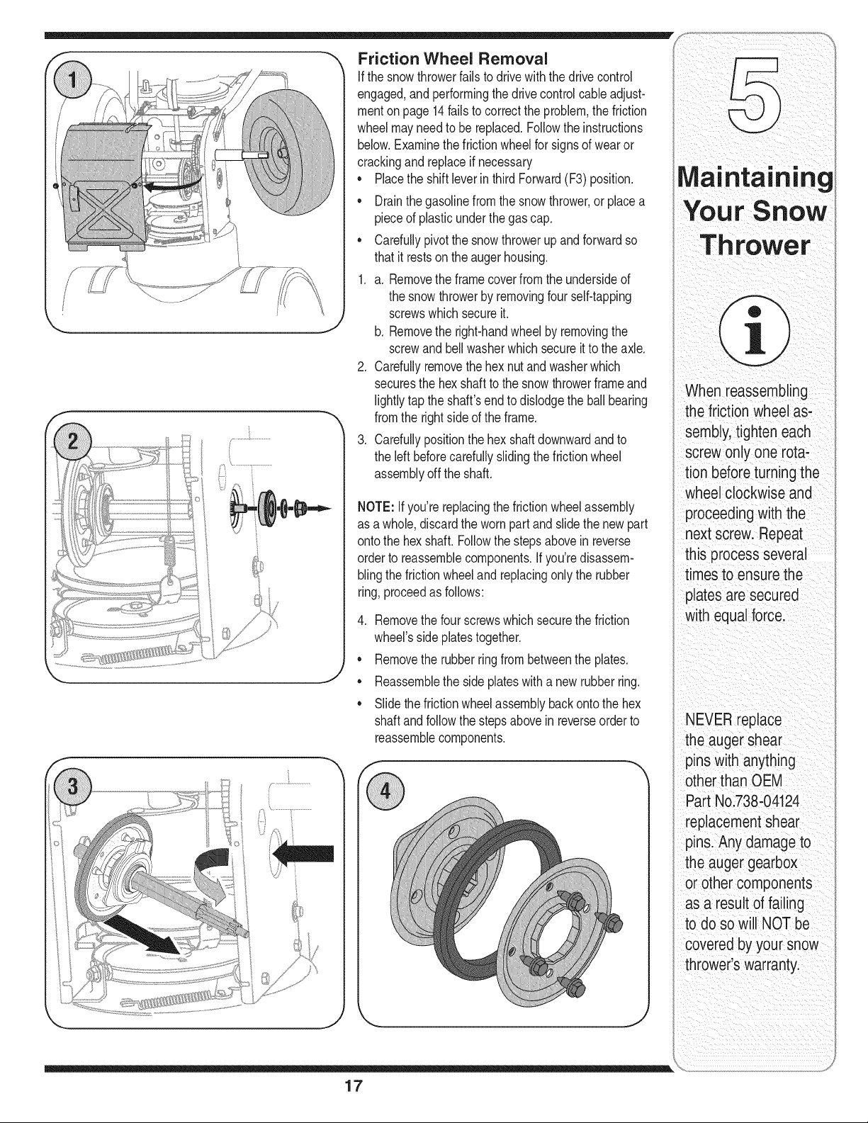
Friction Wheel Removal
If the snowthrowerfails to drivewiththe drivecontrol
engaged,and performingthedrivecontrolcableadjust-
menton page 14fails to correctthe problem,the friction
wheelmayneedto be replaced.Followthe instructions
below.Examinethe frictionwheelfor signsof wearor
crackingand replaceif necessary
• Placethe shiftleverin third Forward(F3) position.
• Drainthe gasolinefromthe snowthrower,or placea
pieceof plasticunderthe gas cap.
Carefullypivotthe snowthrowerup and forwardso
thatit restson the augerhousing.
1. a. Removethe framecoverfromthe undersideof
the snowthrowerby removingfourself-tapping
screwswhichsecureit.
b. Removethe right-handwheelby removingthe
screwandbellwasherwhichsecureit to the axle.
2. Carefullyremovethe hex nutand washerwhich
securesthe hexshaft to the snowthrowerframeand
lightlytap the shaft'sendto dislodgethe ballbearing
fromthe rightsideof the frame.
3. Carefullypositionthehex shaftdownwardandto
the left beforecarefullyslidingthefrictionwheel
assemblyoff the shaft.
NOTE: If you'rereplacingthe frictionwheelassembly
as a whole,discardthe wornpartand slidethe newpart
ontothe hex shaft.Followthe stepsabovein reverse
orderto reassemblecomponents.Ifyou'redisassem-
blingthe frictionwheeland replacingonly the rubber
ring,proceedas follows:
4. Removethe four screwswhichsecurethe friction
wheel'ssideplatestogether.
Removethe rubberringfrombetweenthe plates.
Reassemblethe side plateswith a newrubber ring.
Slidethefrictionwheelassemblybackontothe hex
shaftandfollowthestepsabovein reverseorderto
reassemblecomponents.
17
When reassembling
thefriction wheel as-
sembly,tighten each
screwonly one rota-
tion beforeturning the
wheel clockwise and
proceeding with the
next screw. Repeat
this process several
timesto ensure the
plates are secured
with equal force.
NEVER replace
theauger shear
pins with anything
otherthan OEM
Part No.738-04124
replacementshear
pins.Any damageto
the auger gearbox
or other components
as a result of failing
to do so will NOT be
covered by your snow
thrower'swarranty.
WARNING
Never store snow
thrower with fuel
in tank indoors or
in poorly ventilated
areas, where fuel
fumes may reach an
open flame, spark
or pilot light as on a
furnace, water heater,
clothes dryer or gas
appliance.
Drain fuel into an
approved container
outdoors, away from
any open flame. Be
certain engine is
cool. Do not smoke.
Fuel left in engine
during warmweather
deteriorates and will
cause serious
starting problems.
Do not drain
carburetor if
using fuel stabilizer.
Never use engine or
carburetor cleaning
products in the fuel
tank or permanent
damage may occur.
Ifthe snowthrowerwill not be usedfor30 daysor longer, 1.
or if it is the end of the snow seasonwhenthe last pos-
sibilityof snowis gone,the equipmentneedsto be stored
properly.Followstorageinstructionsbelowto ensuretop 2.
performancefromthe snowthrowerfor manymoreyears.
Preparing Engine 3.
WARNING: Never store snow
thrower with fuel in tank indoors
or in poorly ventilated areas,
where fuel fumes may reach an
open flame, spark or pilot light
as on a furnace, water heater,
clothes dryer or gas appliance.
NOTE:It is importantto preventgum depositsfromform-
ingin essentialfuelsystempartsof the engine suchas
the carburetor,fuel filter,fuel hoseor tank duringstorage.
CAUTION:Alcoholblendedfuels(calledgasoholorusing
ethanolor methanol)canattractmoisturewhichleadsto
separationandformationof acidsduringstorage.Acidic
gas can damagethe fuel systemof anenginewhile in
storage.
To avoidengineproblems,the fuel systemshouldbe
emptiedbeforestoragefor 30 days or longer.Follow
theseinstructionsto prepareyour snowthrowerfor
storage:
_ ARNING" Drain fuel into an ap-
proved container outdoors, away
from any open flame. Be certain
engine is cool. Do not smoke.
Fuel left in engine during warm
weather deteriorates and will
cause serious starting problems.
Removeall gasolinefromthecarburetorand the fuel
tankto preventgumdepositsfromformingon these
partsand harmingtheengine.
Runthe engineuntilthe fuel tankis emptyandit stops
due to lack of fuel.
Draincarburetorbypressingupwardon bowldrain,
locatedbelowthe carburetorcover(referto the
Tecumsehenginemanualfor moredetailedinstruc-
tion).
_ ARNING: Do not drain carbure-
tor if using fuel stabilizer. Never
use engine or carburetor cleaning
products in the fuel tank or
permanent damage may occur.
NOTE:Fuelstabilizer(suchas STA-BIL)is an accept-
ablealternativein minimizingtheformationof fuel gum
depositsduringstorage.Add stabilizerto gasolinein fuel
tankor storagecontainer.Alwaysfollow mix ratiofoundon
stabilizercontainer.Runengineat least 10minutesafter
addingstabilizerto allow it to reachthe carburetor.Do not
draincarburetorif usingfuel stabilizer.
.
Removethe sparkplugand pourone (1) ounceof
engineoilthroughthe sparkplug hole intothe cylinder.
Coversparkplugholewitha rag and crank theengine
severaltimesto distributethe oil. Replacesparkplug.
NOTE:Referto the Tecumsehenginemanualfor more
informationonpreparingthe snowthrowerenginefor
storage.
Preparing Snow Thrower
Whenstoringthe snowthrowerinan unventilatedor
metalstorageshed,care shouldbe takento rustproof
the equipment.Usinga lightoil or silicone,coatthe
equipment,especiallyanychains,springs,bearings
and cables.
2. Removeall dirt fromexteriorof engineandequipment.
3. Followlubricationrecommendationson page12.
4. Storeequipmentina clean,dry area.
18
Problem Cause Remedy
n n r 1 Chokenot nONposton . 1 Movechoketo ON post on
Eg efa sto sta t : :
2, Sparkplugwiredisconnected• 21Connectwireto Sparkplug,
3: Fueitankemptyorstalefue!, &Fill tank with €leanlfreShgasoiine:
Enginenot pi medl ,Primeengineas inStructedin
OpeiatingYouisnowThiOwe[!
5 Faut Sark u 5 C ean adjust gap or repace
, y P P g,
6 BoCke u e .... 6 Ceanfue ne
, df e!n, :
7. Safety keynotin ignitionon engine! I 7: !nse[t keyfully int0the switch.
Engineruns erratic 1. Unitrunningon CHOKE.
1. Movechokeleverto OFFposition.
2. Blockedfuel lineor stale fuel. 2. Cleanfuel line;fill tankwithclean,
freshgasoline.
3. Waterordirt infuel system. 3. Drainfuel tank. Refillwith
freshfuel.
4. Carburetoroutof adjustment. 4. ContactMTDServiceCenter.
Engine overheats 1 carburetornotadjustedproperly, li Contact MTD serViCeCenter:
Excessive 1. Looseparts or damagedauger.
Vibration
Stop engineimmediatelyand
disconnectsparkplugwire.Tighten
all bolts and nuts.If vibration
continues,haveunit servicedby a
MTDServiceCenter.
Unitfails 1. Drivecontrolcablein needof adjust- 1. Adjust drivecontrolcable. Referto
to propel itself merit. "MakingAdjustments".
2. Drivebeltlooseor damaged. 2. Replacedrivebelt.
Unitfails 1. Chuteassemby clogged 1. Stop engineimmediatelyand
to d schame snow I disconnectsparkplugwire•Clean
chuteassemblyandinsideof auge_
housingwith clean-outtool or a
stick
2. Foreignobject lodgedin auger• 2. Stop engineimmediatelyand
disconnectsparkplugwire•
Removeobjectfromaugerwith
clean-outtool or a stick•
3 Augercontro cab e n need of adjust- 3 R_^_.....L_,_uu_^.... L,_,,uu"..... _le_L'r..... u,
ment
• page11.
4 Augerbet ooseor damaged
• " I 4. Referto Maintenancesection
5 Shearp n(s) sheared
5. Replacewithnewshearpin(s)•
19
Trouble:
NOTE:This section
addresses minor
serviCeissues:For
further details, Contact
aMTD authorized
service center or call
1(800) 800-7310for
assistance
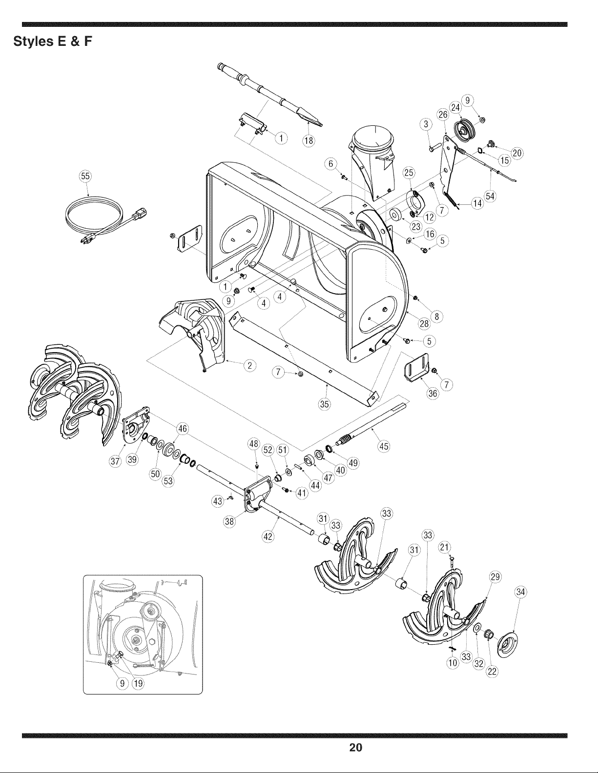
Styles E & F
2O
1. 731-2635 SnowRemovalToolMount
2. 684-04057 ImpellerAssembly,12"Dia.
3. 710-0347 HexScrew,3/8-16,1.75,Gr5
4. 710-0451 Bolt,Carriage,5/16-18,.750Grl
5. 710-0604A Screw, 5/16-18,0.625
6. 710-0703 Screw,Carriage,1/4-20,.750,Gr5
7. 712-04063 Nut,FlangeLock,5/16-18,Nylon
8. 712-04064 Nut,FlangeLock,1/4-20,Nylon
9. 712-04065 Nut,FlangeLock,3/8-16,Nylon
10. 714-04040 CotterPin,Bow-tie
11. 725-0157 Cable,Tie,3/16x .05x 7.4
12. 726-04012 Nut,Push-on,.25 Dia
13. 731-04705 Chute,Adapter5" Dia
14. 732-0611 Spring,Extension,.38OD x 3.6
15. 736-0174 Washer,Wave,.625x .885x .015
16. 736-0242 Washer,Bell, .340x .872x .060
17. 736-0463 Washer,Fiat, .25x .630x .0515
18. 731-2643 SnowRemovaITool
19. 738-0143 Screw,Shoulder,.498x .34,3/8-16
20. 738-0281 Screw,Shoulder,.625x .17,3/8-16
21. 738-04124A ShearPin, .25x 1.50
22. 741-0245 Bearing,HexFlangex .75ID
23. 741-0309 Bearing,Ball, .75IDx 1.85OD
24. 756-0981A FiatPulley,Idler, 2.75OD
25. 790-00075 Housing,Bearing,1.85ID
26. 790-00080 Bracket,Auger Idlerw/ Brake
27. 618-04170 GearboxAssembly,Auger,22"
618-04171 GearboxAssembly,Auger,24"
618-04172 GearboxAssembly,Auger,26"
618-04173 GearboxAssembly,Auger,28"
28. 684-04068 HousingAssembly,Auger22"
684-04069 HousingAssembly,Auger24"
684-04070 HousingAssembly,Auger26"
684-04071 HousingAssembly,Auger28"
* Nonefoundbetweenspiralsonmodelswith22-inchaugerhousing.
* Onefoundbetweenspiralson modelswith 24-inchauger housing.
* Twofoundbetweenspiralsonmodelswith26-inchaugerhousing.
* Threefound betweenspiralson modelswith 28-inchaugerhousing.
29. 684-04107 SpiralAssembly,LH
30. 684-04108 SpiralAssembly,RH
31. 731-04870" Spacer,1.25ODx.75 IDx 1.00
32. 736-0188 Washer,Fiat,.76x 1.49x .06
33. 741-0493A Bushing,Flange,.80 ID x .91OD
34. 790-00087A Housing,1"HexBearing
35. 790-00117 ShavePlate,2.25 x 21.66
790-00120 ShavePlate,2.25 x 23.66
790-00121 ShavePlate,2.25 x 25.66
790-00118 ShavePlate,2.25 x 27.66
36. 784-5580 . SlideShoe
37. 719-0319 Housing,Auger,RH Reduced
38. 719-0320 Housing,Auger,LH Reduced
39. 721-0179 Seal,Oil, .750ID
40. 741-0662 Bearing,Flange,.75x 1.0x .59
41. 710-0642 Screw,Self-tapping,1/4-20,0.750
illustrated
42. 711-04286 Axle, Auger, 22"
711-04285 Axle,Auger,24"
711-04284 Axle,Auger,26"
711-04283 Axle,Auger,28"
43. 714-0161 Key,Hi-pro3/16x 5/8
44. 715-04021 Pin, Dowel,.25 ODx 1.2
45. 717-04126 Shaft,Worm.75OD
46. 717-0528A Gear,Worm20T
47. 718-04071 Collar,Thrust
48. 721-0325 Plug, 1/4x.437
49. 721-0327 Seal,Oil, .75x 1 x .131
50. 736-0351 Washer,Fiat,.760IDx 1.50D
51. 736-3084 Washer,Fiat,.51x 1.12
52. 741-0663 Bearing,Flange,.75x 1.0x .925
53. 741-0661A Bearing,Flange,.75x 1.00x .975
54. 746-04230 ClutchCable,Auger,47.23"
55. 629-0071 ExtentionCord,110V
NOTE: Snowthrowerfeaturesandcomponentsvary by model.NOTall parts listedaboveand pictured
onthe previouspageare standardequipment.
ii ii iiiii _ i i i i
To order replacement
parts, contact
1,800,800=73101
or visit
www,rntdproducts;com,
21
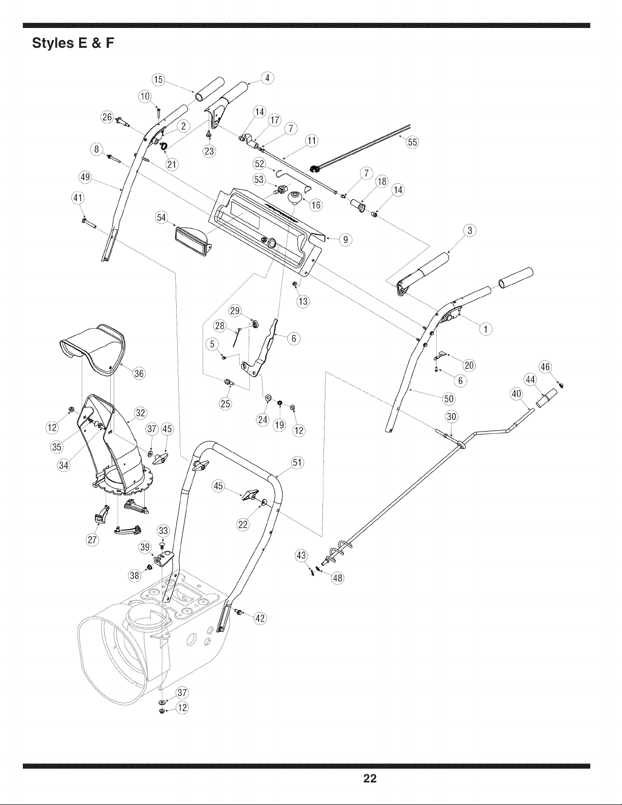
Styles E & F
/
/
22
1. 631-04133 HandleAssembly,ClutchLock, LH
2. 631-04134A HandleAssembly,ClutchLock, RH
3. 684-04105A HandleAss'y,EngagementLH
4. 684-04106A HandleAss'y,EngagementRH
5. 710-0224 Screw,#10-16,0.500
6. 710-04326 Screw,#8-16x.50
7. 710-04354 Screw,1/4-20,.375
8. 710-0606 HexScrew,1/4-20,1.50,Gr5
9. 790-00219 Panel,Handle,(nocutout) E-Style
790-00209 Panel,Handle,(w/cutout) F-Style
10. 710-1233 Screw,Machine,#10-24,1.375
11. 711-04287 PivotRod
12. 712-04063 Nut,FlangeLock,5/16-18,Nylon
13. 712-04064 Nut,FlangeLock,1/4-20,Nylon
14. 712-04081A Nut,Hex, 1/4-20,Shoulder
15. 720-0274 Grip,1.0ID x 5.0
16. 720-04039 Knob,Shift
17. 731-04894A LockPlate
18. 731-04896A Cam,ClutchLock
19. 732-0193 Spring,.39 x .60x .88
20. 732-04219 Spring,ClutchLock
21. 732-04238 Spring,Torsion,0.8156ID x .3038
22. 736-0451 Washer,Saddle,320x .93x .060
23. 735-0199A Bumper,Rubber,.62 ODx .22
24. 736-0262 Washer,Fiat, .385x .870x .092
25. 738-04118 Bolt,Shoulder,5/16-18x 0.905
26. 738-04122 Screw,Shoulder,.43 x 1.3,1/4-20
27. 731-04869 Chute,FlangeKeeper
28. 746-04228 Cable,SpeedSelector
29. 746-0605 Houlder,Cable Barrel,LH
30. 747-04263 Eye Bolt,ChuteCrank
31. 790-00202 Shift Lever
32. 731-04912A Chute,Lower,5.0 Dia.
33. 710-0276 Bolt,Carriage,5/16-18,1.0
34. 710-04071 Bolt,Carriage,5/16-18,1.0
35. 710-0451 Bolt,Carriage,5/16-18,.750
36. 731-04426A Chute,Upper,w/Label
37. 736-0159 Washer,.349x .879x .063
38. 741-0475 Bushing,Plastic,.380
39. 784-5647 Bracket,ChuteCrank
40. 684-04104 CrankAssembly,Chute
41. 710-0449 Screw,Carriage,5/16-18,2.25
42. 710-1260A Screw,5/16-18,0.75,Gr5
43. 714-0104 Pin, Cotter,.072x 1.13
44. 720-0201A CrankKnob,1.0Dia.x 3.2, Black
45. 720-0284 KnobAssembly,WingNut,5/16-18
46. 726-0100 Cap,Push,3/8 Rod
47. 735-0234 Grommet,.44ID x .94 ODx .50
48. 736-0185 Washer,Fiat,.375x .738x .063
49. 749-04141 Handle,Upper,RH
50. 749-04142 Handle,Upper,LH
51. 749-04138 Handle,Lower
52. 747-1136 Retainer,Lens
53. 725-1658 Lamp,Halogen,12V,27W
54. 725-1672 LensAssembly,Lamp
55. 725-04220 Wire Harness,Lamp
NOTE:A lampcannotbeaddedto a unitthat did come come factory-equippedwith a lamp.
NOTE: Snowthrowerfeaturesandcomponentsvary by model.NOTall parts listedaboveand pictured
onthe previouspageare standardequipment.
23
illustrated
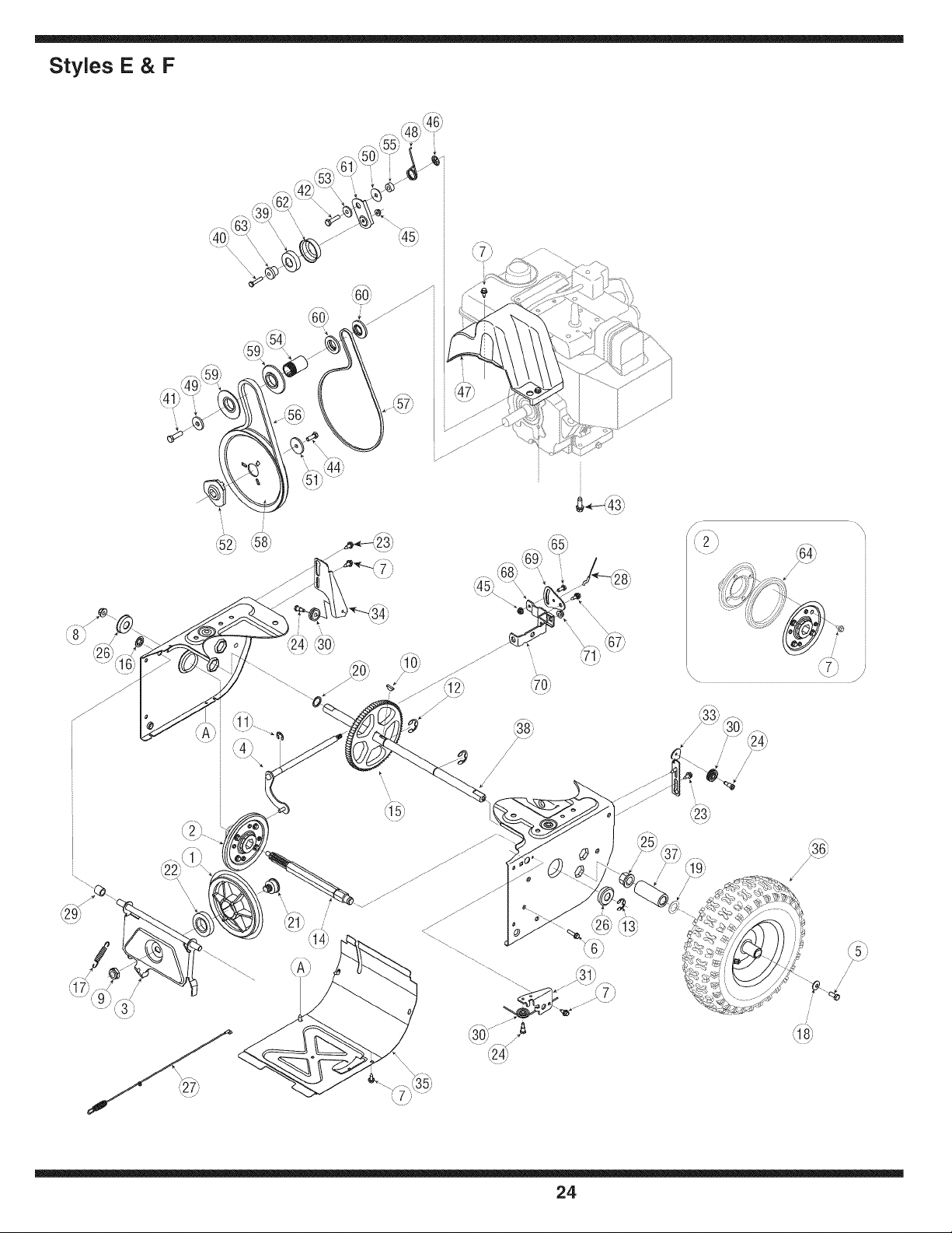
Styles E & F
/
/
\\\ _ /
24
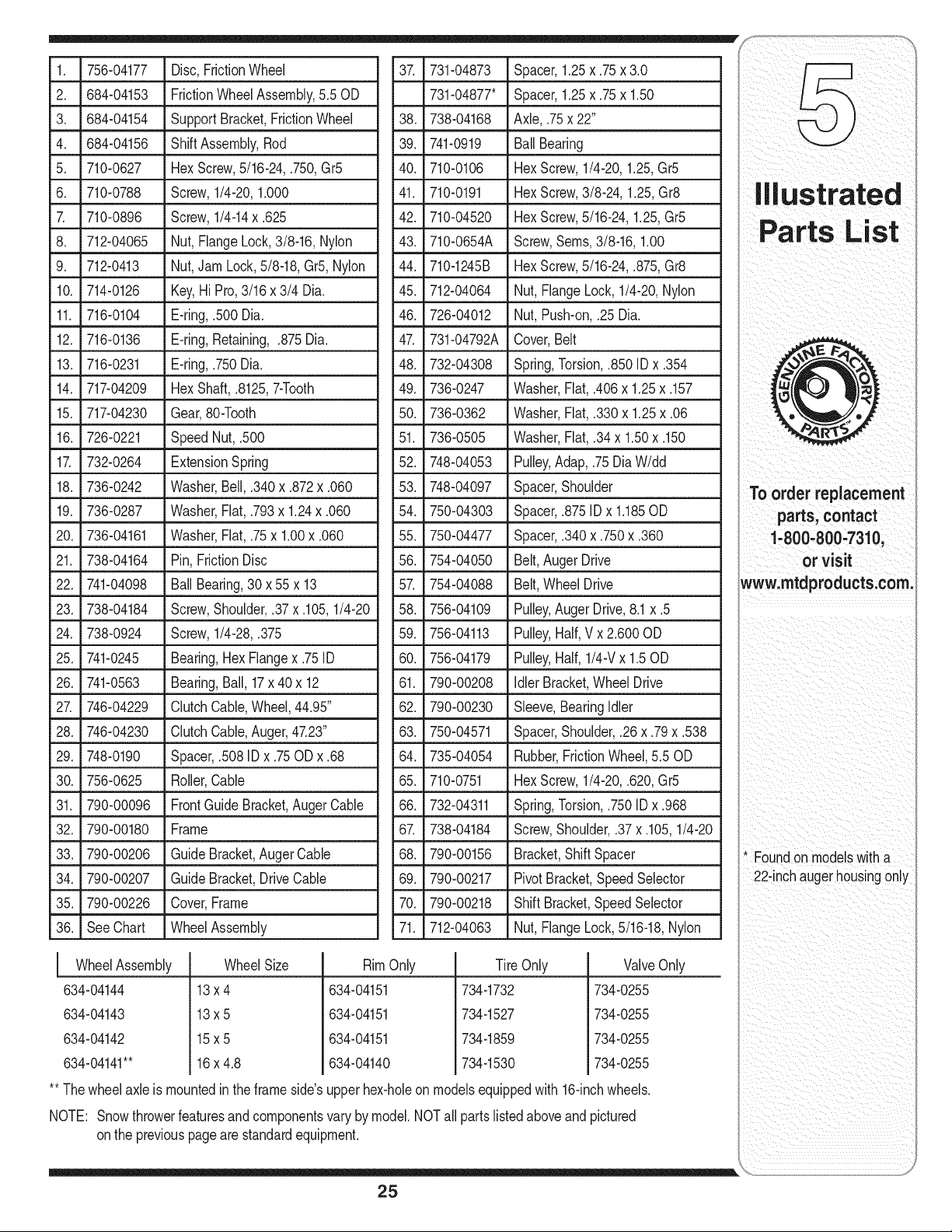
1. 756-04177 Disc,FrictionWheel
2. 684-04153 FrictionWheelAssembly,5.50D
3. 684-04154 SupportBracket,FrictionWheel
4. 684-04156 ShiftAssembly,Rod
5. 710-0627 HexScrew,5/16-24,.750,Gr5
6. 710-0788 Screw,1/4-20,1.000
7. 710-0896 Screw,1/4-14x .625
8. 712-04065 Nut,FlangeLock,3/8-16,Nylon
9. 712-0413 Nut,Jam Lock,5/8-18,Gr5, Nylon
10. 714-0126 Key,Hi Pro,3/16x 3/4 Dia.
11. 716-0104 E-ring,.500Dia.
12. 716-0136 E-ring,Retaining,.875Dia.
13. 716-0231 E-ring,.750Dia.
14. 717-04209 HexShaft,.8125,7-Tooth
15. 717-04230 Gear,80-Tooth
16. 726-0221 SpeedNut, .500
17. 732-0264 ExtensionSpring
18. 736-0242 Washer,Bell, .340x .872x .060
19. 736-0287 Washer,Fiat, .793x 1.24x .060
20. 736-04161 Washer,Fiat, .75x 1.00x .060
21. 738-04164 Pin,FrictionDisc
22. 741-04098 BallBearing,30x 55x 13
23. 738-04184 Screw,Shoulder,.37 x .105,1/4-20
24. 738-0924 Screw,1/4-28,.375
25. 741-0245 Bearing,HexFlangex .75ID
26. 741-0563 Bearing,Ball, 17x 40 x 12
27. 746-04229 ClutchCable,Wheel,44.95"
28. 746-04230 ClutchCable,Auger,47.23"
29. 748-0190 Spacer,.508 IDx .75ODx .68
30. 756-0625 Roller,Cable
31. 790-00096 FrontGuideBracket,AugerCable
32. 790-00180 Frame
33. 790-00206 GuideBracket,Auger Cable
34. 790-00207 GuideBracket,DriveCable
35. 790-00226 Cover,Frame
36. SeeChart WheelAssembly
37. 731-04873 Spacer,1.25x .75x 3.0
731-04877" Spacer,1.25x .75x 1.50
38. 738-04168 Axle,.75x 22"
39. 741-0919 Ball Bearing
40. 710-0106 HexScrew,1/4-20,1.25,Gr5
41. 710-0191 HexScrew,3/8-24,1.25,Gr8
42. 710-04520 HexScrew,5/16-24,1.25,Gr5
43. 710-0654A Screw,Seres,3/8-16, 1.00
44. 710-1245B HexScrew,5/16-24,.875,Gr8
45. 712-04064 Nut, FlangeLock,1/4-20,Nylon
46. 726-04012 Nut, Push-on,.25Dia.
47. 731-04792A Cover,Belt
48. 732-04308 Spring,Torsion,.850 ID x .354
49. 736-0247 Washer,Fiat,.406x 1.25x .157
50. 736-0362 Washer,Fiat,.330x 1.25x .06
51. 736-0505
l Wheel Assembly
634-04144
634-04143
634-04142
634-04141**
Wheel Size
13x4
13x5
15x5
16x 4.8
illustrated
Washer,Fiat,.34 x 1.50x .150
52. 748-04053 Pulley,Adap, .75UiaW/dd
53. 748-04097 Spacer,Shoulder
54. 750-04303 Spacer,.875IDx 1.185OD
55. 750-04477 Spacer,.340x .750x .360
56. 754-04050 Belt,Auger Drive
57. 754-04088 Belt,WheelDrive
58. 756-04109 Pulley,Auger Drive,8.1x .5
59. 756-04113 Pulley,Half,Vx 2.600OD
60. 756-04179 Pulley,Half,1/4-Vx 1.50D
61. 790-00208 idler Bracket,WheelDrive
62._790-00230 Sleeve, Bearingidler
63. 750-04571 Spacer,Shoulder,.26 x .79x .538
64. 735-04054 Rubber,FrictionWheel,5.50D
65. 710-0751 HexScrew,1/4-20,.620,Gr5
66. 732-04311 Spring,Torsion,.750ID x .968
67. 738-04184 Screw,Shoulder,.37x .105,1/4-20
68. 790-00156 Bracket,ShiftSpacer
69. 790-00217 PivotBracket,SpeedSelector
70._790-00218 _ Shift Bracket,SpeedSelector
71. 712-04063 Nut, FlangeLock,5/16-18,Nylon
Tin Only
734-1732
734-1527
734-1859
734-1530
ValveOnly
734-0255
734-0255
734-0255
734-0255
RimOnly
634-04151
634-04151
634-04151
634-04140
** Thewheelaxle is mountedinthe frameside'supperhex-holeonmodelsequippedwith16-inchwheels.
NOTE: Snowthrowerfeaturesandcomponentsvary by model.NOTall parts listedaboveand pictured
onthe previouspageare standardequipment.
To order replacement
parts, contact
1-800-800-7310,
or visit
www.rntdproducts.corn.
* Foundon modelswith a
22-inchauge"housingonly
25

NOTES
26

NOTES
27
MANUFACTURER'S LiMiTED WARRANTY FOR
The limitedwarrantysetforthbelowisgivenby MTDLLCwith respectto
newmerchandisepurchasedandusedin the UnitedStates,itsposses-
sionsandterritories.
"MTD"warrantsthisproductagainstdefectsin materialand workmanship
for a periodof two (2) yearscommencingon the dateof originalpurchase
andwill,at its option,repairor replace,free of charge,anypart foundto
bedefectiveinmaterialsor workmanship.This limitedwarrantyshallonly
applyif this producthas beenoperatedandmaintainedinaccordance
withthe Operator'sManualfurnishedwith the product,andhas not been
subjectto misuse,abuse,commercialuse, neglect,accident,improper
maintenance,alteration,vandalism,theft,fire,water,ordamagebecause
of otherperilor naturaldisaster.Damageresultingfrom the installationor
useof any part,accessoryor attachmentnotapprovedby MTDfor use
withthe product(s)coveredbythis manualwill voidyourwarrantyas to
any resultingdamage.
Normalwearpartsarewarrantedto befree fromdefectsinmaterialand
workmanshipfor a periodof thirty (30) days fromthe dateof purchase.
Normalwearpartsinclude,butare notlimitedto itemssuchas: batteries,
belts,blades,bladeadapters,grass bags, riderdeck wheels,seats,snow
throwerskidshoes,shaveplates,augerspiralrubberandtires.
HOW TO OBTAIN SERVICE: Warranty service is available,WITH
PROOFOF PURCHASE, through your local authorized service
dealer. To locate the dealer in your area, check your Yellow Pages, or
contact MTD LLC at RO. Box 361131,Cleveland, Ohio 44136-0019,or
call 1-800-800-7310or 1-330-220-4683or log on to our Web site at
www.mtdproducts.com.
Thislimitedwarrantydoesnot providecoverageinthe followingcases:
a. Theengineor componentpartsthereof.These itemsmaycarrya
separatemanufacturer'swarranty.Referto applicablemanufacturer's
warrantyfor termsand conditions.
b. Logsplitterpumps,valves,and cylindershavea separateone year
warranty.
c. Routinemaintenanceitemssuchas lubricants,filters,blade
sharpening,tune-ups,brakeadjustments,clutchadjustments,deck
adjustments,andnormaldeteriorationof the exteriorfinishdueto use
orexposure.
d. Servicecompletedby someoneotherthananauthorizedservice
dealer.
e. MTDdoes notextendany warrantyfor productssoldor exported
outsideof the UnitedStates,its possessionsand territories,except
thosesoldthroughMTD'sauthorizedchannelsof exportdistribution.
f. Replacementpartsthatarenot genuineMTDparts.
g. Transportationchargesand servicecalls.
No impliedwarranty,includingany impliedwarranty of merchant-
ability of fitness for a particularpurpose,applies after the applicable
periodof express written warranty above as to the partsas identi-
fied. No other express warranty, whether written or oral, except as
mentionedabove, givenby any personor entity,includinga dealer
or retailer,with respect to any product,shallbind MTD.Duringthe
periodof the warranty, the exclusive remedyis repairor replacement
of the productas set forth above.
The provisionsas set forth in this warranty providethe sole and
exclusive remedy arising from the sale. MTDshall not be liable
for incidentalor consequential loss or damage including,without
limitation, expenses incurredfor substitute or replacementlawn care
services or for rentalexpenses to temporarily replacea warranted
product.
Somestatesdo not allowtheexclusionor limitationof incidentalor
consequentialdamages,or limitationson howlonganimpliedwarranty
lasts,so the aboveexclusionsor limitationsmay notapplyto you.
In no eventshall recoveryof any kind be greaterthan theamountof the
purchasepriceof the productsold.Alterationof safetyfeatures of the
productshall void this warranty. Youassumethe risk and liability for
loss, damage,or injuryto youandyour propertyand/orto othersandtheir
propertyarisingout of the misuseor inabilityto use theproduct.
Thislimitedwarrantyshall notextendto anyoneotherthanthe original
purchaseror to the personfor whom itwas purchasedas a gift.
HOWSTATELAWRELATESTO THISWARRANTY: Thislimitedwar-
rantygivesyouspecificlegalrights,andyou mayalso haveother rights
whichvaryfromstateto state.
IMPORTANT: OwnermustpresentOriginalProofof Purchaseto obtain
warrantycoverage.
MTD LLC, P.O. BOX 361131 CLEVELAND, OHIO 44136-0019; Phone: 1-800-800-7310, 1-330-220-4683

