
Extension Kit
DW7050, DW7080
WARNING: For your own safety, read the miter saw instruction
manual before using any accessory. Failure to heed these warnings
may result in personal injury and serious damage to the miter saw
and the accessory. When servicing this tool, use only identical
replacement parts.
WARNING: To reduce the risk of serious personal injury,
turn tool off and disconnect tool from power source before
making any adjustments or removing/installing attachments or
accessories.
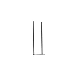
FOR MITER SAWS WITH U-SHAPED SUPPORTS (FIG. 1)
The extension kit can be used on either or both sides of the saw.
Assemble the extension kit as shown:
1. Install the self-tapping stud into the hole underneath the saw,
threading in the shorter end using a 1/2" (13 mm) wrench.
2. Install the stop-washer and screw into the rod nearest the front
(DW7050).
3. Clamp the rods against the miter saw unit by tightening the
clamping bracket nut.
4. Align end plate with top of work surface and tighten locknuts.
Kit de rallonges DW7050, DW7080
AVERTISSEMENT : Pour votre sécurité, lire le manuel de
l’utilisateur de la scie à onglet avant l’utilisation de tout accessoire.
Tout manquement à ces avertissements augmente les risques de
dommages corporels, et les risques de sérieusement endommager
la scie à onglet et ses accessoires. Lors de l’entretien de cet outil,
n’utiliser que des pièces de rechange identiques.
AVERTISSEMENT : Pour réduire tout risque de dommages
corporels graves, arrêter et débrancher l’outil avant tout
réglage ou avant de retirer ou installer toute pièce ou tout
accessoire.
Français
English
DEWALT Industrial Tool Co., 701 Joppa Road, Baltimore, MD 21286
(MAR09) Part No. N022966 DW7050, DW7080 Copyright © 1996, 2008, 2009 D
EWALT
The following are trademarks for one or more D
EWALT power tools: the yellow and black color scheme; the “D” shaped air intake grill; the array of
pyramids on the handgrip; the kit box configuration; and the array of lozenge-shaped humps on the surface of the tool.
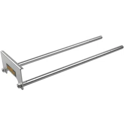
FOR MITER SAWS WITH HOLES (FIG. 2)
1. Slide rods into the holes as shown in Figure 2A.
2. Align end plate with top of work surface and tighten locknuts.
3. Insert the self-tapping screw into hole to lock the rods in place
(Fig. 2B).
WARNING: Do not lift, support, or carry the miter saw by the
extension kit. To do so may cause tipping and loss of control,
leading to personal injury.
NOTE: Before transporting miter saw, remove the extension or
telescope it in toward the saw.
FIG. 1
FIG. 2A
HOLES
TROUS
ORIFICIOS
FIG. 2B
SELF-TAPPING
SCREW
VIS
AUTO-TARAUDEUSE
TORNILLO
AUTORROSCANTE
WARNIN
G
:
AL
PROP
ERLY
B
RODS (2)
TIGES (2)
VARILLAS (2)
STOP WASHER
AND SCREW
RONDELLE
D’ARRÊT ET VIS
ARANDELA DE
TOPE Y
TORNILLO
SELF-TAPPING STUD
MONTANT
AUTOTARAUDEUR
TACHÓN
AUTORROSCANTE
CLAMPING BRACKET
DISPOSITIF
DE FIXATION
SOPORTE
DE FIJACIÓN
LOCKNUTS (2)
CONTRE-ÉCROUS (2)
CONTRATUERCAS (2)
ENDPLATE
BORD
PLACA TERMINAL

Kit de extensión
DW7050, DW7080
ADVERTENCIA: Para su seguridad, lea el manual de instrucciones
de la sierra ingleteadora antes de utilizar cualquier accesorio. De no
seguir estas advertencias podrían producirse lesiones corporales y
graves daños a la sierra ingleteadora y al accesorio. Cuando realice
el mantenimiento de esta herramienta, utilice únicamente repuestos
idénticos.
ADVERTENCIA: Para reducir el riesgo de lesiones corporales
graves, apague la herramienta y desconéctela de la fuente de
alimentación antes de realizar ajustes o de quitar o poner
accesorios.
PARA SIERRAS INGLETEADORAS CON SOPORTES EN U
(FIG. 1)
El kit de extensión puede utilizarse en uno o ambos lados de la
sierra. Ensamble el kit de extensión como se muestra:
1. Instale el tachón autorroscante en el orificio debajo de la sierra,
enroscando el extremo más corto con una llave de 13 mm
(1/2 pulg.).
2. Instale la arandela de tope y atornille a la varilla más cercano a
la parte de adelante (DW7050).
3. Sujete las varillas contra la unidad de la sierra ingleteadora
ajustando la tuerca del soporte de fijación.
4. Alinee la placa terminal con la parte de arriba de la superficie
de trabajo y ajuste las contratuercas.
PARA SIERRAS INGLETEADORAS CON ORIFICIOS (FIG. 2)
1. Deslice las varillas en los orificios como lo muestra la
Figura 2A.
2. Alinee la placa terminal con la parte de arriba de la superficie
de trabajo y ajuste las contratuercas.
3. Inserte el tornillo autorroscante en el orificio para sujetar las
varillas en su lugar (Fig. 2B).
ADVERTENCIA: No levante, soporte ni recoja la sierra
ingleteadora desde el kit de extensión. Esto haría que se volteara y
perdiera el control sobre ella, lo que llevaría a lesiones corporales.
NOTA: Antes de transportar la sierra ingleteadora, quite la
extensión o repliéguela hacia dentro de la sierra.
Español
POUR LES SCIES À ONGLET AVEC SUPPORTS EN U (FIG. 1)
Le kit de rallonges peut être installé d’un côté de la scie comme de
l’autre, ou de chaque côté. Assemblez le kit de rallonges comme
illustré :
1. Installez le montant autotaraudeur dans le trou sous la scie,
en vissant l’embout le plus court à l’aide d’une clé de 13 mm
(1/2 po).
2. Insérez la rondelle d’arrêt et la vis dans la tige la plus à l’avant
(DW7050).
3. Arrimez les tiges contre le dispositif de scie à onglet en
resserrant l’écrou du dispositif de fixation.
4. Alignez le bord avec celui de la surface de travail et resserrez
les contre-écrous.
POUR LES SCIES À ONGLET AVEC TROUS (FIG. 2)
1. Insérez les tiges dans les trous, comme illustré en figure 2A.
2. Alignez le bord avec celui de la surface de travail, et resserrez
les contre-écrous.
3. Insérez la vis auto-taraudeuse dans le trou pour verrouiller les
tiges en place (fig. 2B).
AVERTISSEMENT : Ne pas soulever, soutenir ou transporter la
scie à onglet à l’aide des rallonges. Cela pourrait provoquer culbute
de la scie et perte de contrôle, et poser des risques de dommages
corporels.
REMARQUE : Avant de transporter la scie à onglet, retirer toute
rallonge ou les replier contre la scie.