Loading ...
Loading ...
Loading ...
Mounting and Using Cutting
(Type 1) Wheels
Cutting wheels include diamond wheels and abrasive discs. Abrasive
cutting wheels for metal and concrete use are available. Diamond
blades for concrete cutting can also be used.
WARNING: A closed, 2-sided cutting wheel guard is not included
with this tool but is re quired when using cutting wheels. Fail ure to use
proper flange and guard can re sult in injury resulting from wheel
breakage and wheel contact. See the Accessories Chart for more
information.
MOUNTING CLOSED (TYPE 1) GUARD (FIG. 18 – 20)
WARNING: If present, the ONE TOUCH™ guard screw, lever and
spring must be removed before attempting to mount the closed
(Type1) guard. The removed parts must be retained and reinstalled
to use the ONE TOUCH™ guard. Noting the position of these parts
before disassembly will aid in reassembly.
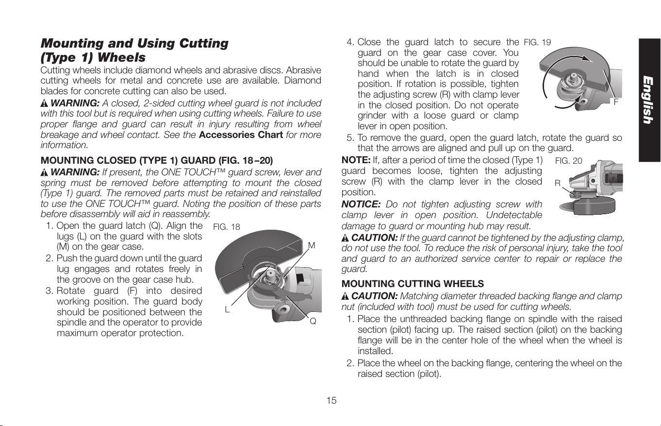
1. Open the guard latch (Q). Align the
Q
L
M
FIG. 18
lugs (L) on the guard with the slots
(M) on the gear case.
2. Push the guard down until the guard
lug engages and rotates freely in
the groove on the gear case hub.
3. Rotate guard (F) into desired
working position. The guard body
should be positioned between the
spindle and the operator to provide
maximum operator protection.
4. Close the guard latch to secure the
F
FIG. 19
guard on the gear case cover. You
should be unable to rotate the guard by
hand when the latch is in closed
position. If rotation is possible, tighten
the adjusting screw (R) with clamp lever
in the closed position. Do not operate
grinder with a loose guard or clamp
lever in open position.
5. To remove the guard, open the guard latch, rotate the guard so
that the arrows are aligned and pull up on the guard.
NOTE: If, after a period of time the closed (Type 1)
R
FIG. 20
guard becomes loose, tighten the adjusting
screw (R) with the clamp lever in the closed
position.
NOTICE: Do not tighten adjusting screw with
clamp lever in open position. Undetectable
damage to guard or mounting hub may result.
CAUTION: If the guard cannot be tightened by the adjusting clamp,
do not use the tool. To reduce the risk of personal injury, take the tool
and guard to an authorized service center to repair or replace the
guard.
MOUNTING CUTTING WHEELS
CAUTION: Matching diameter threaded backing flange and clamp
nut (included with tool) must be used for cutting wheels.
1. Place the unthreaded backing flange on spindle with the raised
section (pilot) facing up. The raised section (pilot) on the backing
flange will be in the center hole of the wheel when the wheel is
installed.
2. Place the wheel on the backing flange, centering the wheel on the
raised section (pilot).
English
15
Loading ...
Loading ...
Loading ...