Loading ...
Loading ...
Loading ...
WARNING: To prevent personal injury, always disconnect the plug from the
power source when making any adjustment.
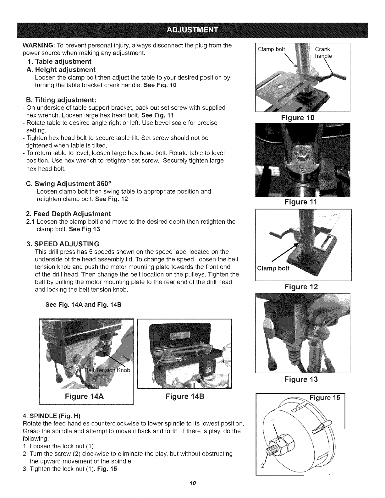
1. Table adjustment
A. Height adjustment
Loosen the clamp bolt then adjust the table to your desired position by
turning the table bracket crank handle. See Fig. 10
B. Tilting adjustment:
=On underside of table support bracket, back out set screw with supplied
hex wrench. Loosen large hex head bolt. See Fig. 11
- Rotate table to desired angle right or left. Use bevel scale for precise
setting.
- Tighten hex head bolt to secure table tilt. Set screw should not be
tightened when table is tilted.
- To return table to level, loosen large hex head bolt. Rotate table to level
position. Use hex wrench to retighten set screw. Securely tighten large
hex head bolt.
C. Swing Adjustment 360 °
Loosen clamp bolt then swing table to appropriate position and
retighten clamp bolt. See Fig. 12
2. Feed Depth Adjustment
2.1 Loosen the clamp bolt and move to the desired depth then retighten the
clamp bolt. See Fig 13
= SPEED ADJUSTING
This drill press has 5 speeds shown on the speed label located on the
underside of the head assembly lid. To change the speed, loosen the belt
tension knob and push the motor mounting plate towards the front end
of the drill head. Then change the belt location on the pulleys. Tighten the
belt by pulling the motor mounting plate to the rear end of the drill head
and locking the belt tension knob.
Clamp bolt Crank
handle
Figure 10
Figure 11
Clamp bolt
Figure 12
See Fig. 14A and Fig. 14B
Figure 14A Figure 14B
4. SPINDLE (Fig. H)
Rotate the feed handles counterclockwise to lower spindle to its lowest position.
Grasp the spindle and attempt to move it back and forth. If there is play, do the
following:
1. Loosen the lock nut (1).
2. Turn the screw (2) clockwise to eliminate the play, but without obstructing
the upward movement of the spindle.
3. Tighten the lock nut (1). Fig. 15
Figure 13
Figure 15
10
Loading ...
Loading ...
Loading ...