GLXD4
Wireless Receiver
The Shure GLXD4 Wireless Receiver online user guide.
Version: 6.4 (2022-G)

Shure Incorporated
2/32
Table of Contents
GLXD4 Wireless Receiver 3
IMPORTANT SAFETY INSTRUCTIONS 3
WARNING 4
Note: 4
Australia Warning for Wireless 4
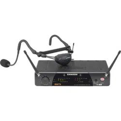
System Overview 4
Accessories 5
Furnished Accessories 5
Optional Accessories 5
Quick Start 5
GLXD4 Receiver Controls and Connectors 7
Receiver Screen 9
Transmitters 10
Transmitter Status LED 11
Wearing the Bodypack Transmitter 11
Wearing the Headworn Microphone 12
Correct Microphone Placement 12
Batteries and Charging 12
Receiver Charging Bay 13
Charging from an AC Power Source 13
Charging from a USB Port 13
LED Status During Charging 14
Installing Transmitter Batteries 14
Charging Times and Transmitter Runtimes 15
Important Tips for Care and Storage of Shure Recharge
able Batteries 15
Multiple Receiver Systems 15
Setting Up Receivers and Transmitters 16
Manually Linking a Transmitter to a Receiver 16
Combo Systems 17
2.4 GHz Spectrum Overview 17
Overcoming the Challenges of 2.4GHz 17
Coexisting with Wi-Fi 17
Challenging Wireless Environments 17
Tips and Methods to Improve Wireless System Perfor
mance 18
2.4 GHz Frequency Tables 18
Firmware 19
Connect to the Computer 20
Operation 20
Gain Adjustment 20
Locking and Unlocking the Controls 21
Identifying Linked Transmitters and Receivers with Re
mote ID 21
Manually Selecting a Group and Channel 21
Troubleshooting 22
Resetting Components 24
Resetting the Receiver 24
Resetting the Transmitter 24
Specifications 24
Pin Assignments 26
Dimensions 27
Certifications 30
Information to the user 32
Shure Incorporated
3/32
1.
2.
3.
4.
5.
6.
7.
8.
9.
10.
11.
12.
13.
14.
15.
16.
17.
18.
19.
20.
21.
GLXD4
Wireless Receiver
IMPORTANT SAFETY INSTRUCTIONS
READ these instructions.
KEEP these instructions.
HEED all warnings.
FOLLOW all instructions.
DO NOT use this apparatus near water.
CLEAN ONLY with dry cloth.
DO NOT block any ventilation openings. Allow sufficient distances for adequate ventilation and install in accordance
with the manufacturer’s instructions.
DO NOT install near any heat sources such as open flames, radiators, heat registers, stoves, or other apparatus (in
cluding amplifiers) that produce heat. Do not place any open flame sources on the product.
DO NOT defeat the safety purpose of the polarized or grounding type plug. A polarized plug has two blades with one
wider than the other. A grounding type plug has two blades and a third grounding prong. The wider blade or the third
prong are provided for your safety. If the provided plug does not fit into your outlet, consult an electrician for replace
ment of the obsolete outlet.
PROTECT the power cord from being walked on or pinched, particularly at plugs, convenience receptacles, and the
point where they exit from the apparatus.
ONLY USE attachments/accessories specified by the manufacturer.
USE only with a cart, stand, tripod, bracket, or table specified by the manufacturer, or sold with the apparatus. When a
cart is used, use caution when moving the cart/apparatus combination to avoid injury from tip-over.
UNPLUG this apparatus during lightning storms or when unused for long periods of time.
REFER all servicing to qualified service personnel. Servicing is required when the apparatus has been damaged in any
way, such as power supply cord or plug is damaged, liquid has been spilled or objects have fallen into the apparatus,
the apparatus has been exposed to rain or moisture, does not operate normally, or has been dropped.
DO NOT expose the apparatus to dripping and splashing. DO NOT put objects filled with liquids, such as vases, on the
apparatus.
The MAINS plug or an appliance coupler shall remain readily operable.
The airborne noise of the Apparatus does not exceed 70dB (A).
Apparatus with CLASS I construction shall be connected to a MAINS socket outlet with a protective earthing connec
tion.
To reduce the risk of fire or electric shock, do not expose this apparatus to rain or moisture.
Do not attempt to modify this product. Doing so could result in personal injury and/or product failure.
Operate this product within its specified operating temperature range.
Explanation of Symbols
Caution: risk of electric shock
Shure Incorporated
4/32
•
•
•
•
•
•
•
•
•
•
Caution: risk of danger (See note.)
Direct current
Alternating current
On (Supply)
Equipment protected throughout by DOUBLE INSULATION or REINFORCED INSULATION
Stand-by
Equipment should not be disposed of in the normal waste stream
WARNING: Danger of explosion if incorrect battery replaced. Operate only with AA batteries.
WARNING: Battery packs shall not be exposed to excessive heat such as sunshine, fire, or the like.
WARNING
Battery packs may explode or release toxic materials. Risk of fire or burns. Do not open, crush, modify, disassemble, heat
above 140°F (60°C), or incinerate
Follow instructions from manufacturer
Never put batteries in mouth. If swallowed, contact your physician or local poison control center
Do not short circuit; may cause burns or catch fire
Do not charge or use battery packs with other than specified Shure products
Dispose of battery packs properly. Check with local vendor for proper disposal of used battery packs
Note:
This equipment is intended to be used in professional audio applications.
EMC conformance is based on the use of supplied and recommended cable types. The use of other cable types may de
grade EMC performance.
Use this battery charger only with the Shure charging modules and battery packs for which it is designed. Use with other
than the specified modules and battery packs may increase the risk of fire or explosion.
Changes or modifications not expressly approved by Shure Incorporated could void your authority to operate this equip
ment.
Note: Use only with the included power supply or a Shure-approved equivalent.
Australia Warning for Wireless
This device operates under an ACMA class licence and must comply with all the conditions of that licence including operating
frequencies. Before 31 December 2014, this device will comply if it is operated in the 520-820 MHz frequency band.
WARNING: After 31 December 2014, in order to comply, this device must not be operated in the 694-820 MHz band.
System Overview
The new groundbreaking GLXD Wireless Systems from Shure combine the leading edge of Automatic Frequency Manage
ment technology with best-in-class intelligent lithium-ion battery rechargeability, world-renowned microphones and unparalleled
design and construction. Available in a wide offering of bodypack and handheld configurations - including vocal, headset and
Shure Incorporated
5/32
•
•
•
•
•
•
•
•
presenter systems as well as traditional guitar options. The revolutionary GLX-D Wireless Systems define the newest standard
for seamless ease of operation and exceptional digital audio clarity.
Exceptional digital audio clarity
Operates in 2.4 GHz spectrum, available worldwide
Rechargeable batteries deliver cost-efficiency and up to 11.5 hours of runtime
Adjustable transmitter gain to optimize audio signal
Automatically moves away from interference without audio interruption
RF back-channel for remote control of transmitter functions
Globally-unlicensed 2.4 GHz frequency band allows operation of up to 4 compatible systems in a typical setting and up to
8 compatible systems under ideal conditions
Automatic transmitter power-off to conserve battery life when transmitter is not in use
Accessories
Furnished Accessories
Power Supply PS43
Carrying Case 95E16526
Shure Lithium-Ion Rechargeable Battery SB902A
USB Cable, Type A to Micro-B 95A21651
* Only included with GLXD14 or GLXD24 systems.
Optional Accessories
Black Bodypack Pouch WA582B
Quick Start
To reduce set up time, the transmitter and receiver automatically link to form an audio channel the first time they are powered
on and never have to be linked again.
Note: When setting up multiple receiver systems, turn on and link each transmitter/receiver pair one at a time to prevent cross-linking.
Shure Incorporated
6/32
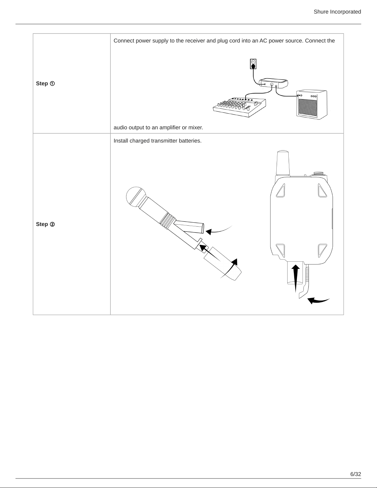
Step ①
Connect power supply to the receiver and plug cord into an AC power source. Connect the
audio output to an amplifier or mixer.
Step ②
Install charged transmitter batteries.
Shure Incorporated
7/32
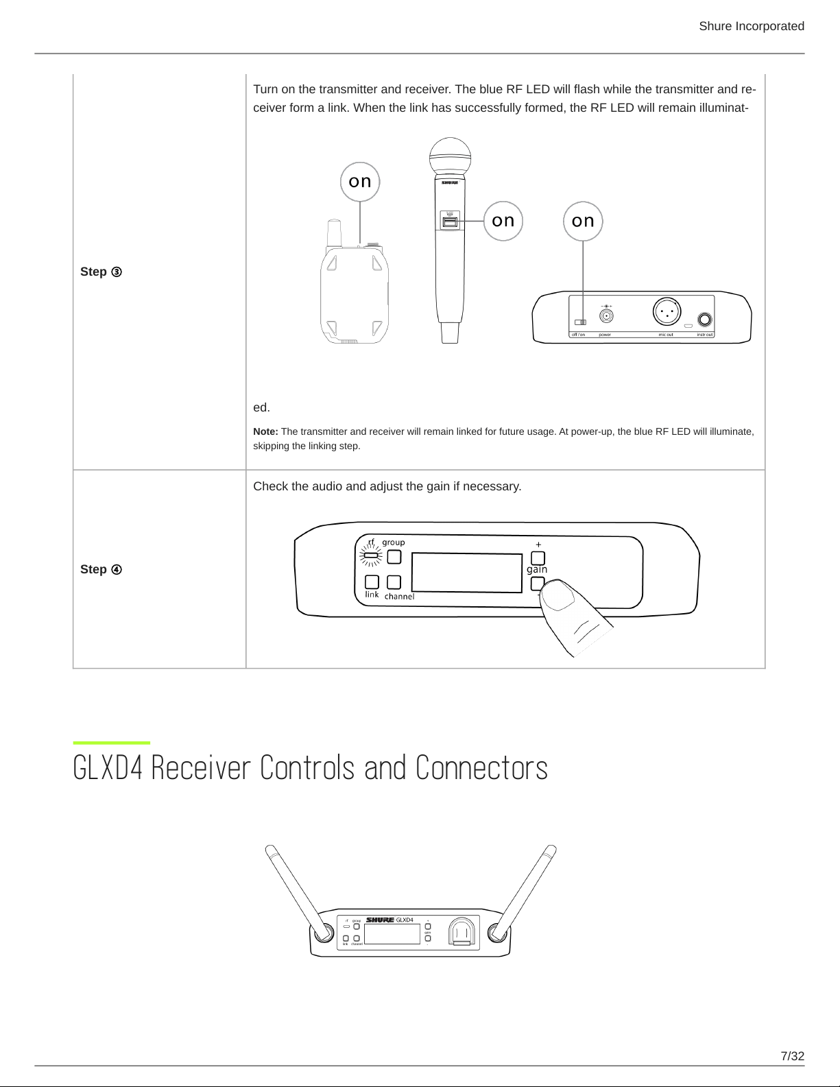
Step ③
Turn on the transmitter and receiver. The blue RF LED will flash while the transmitter and re
ceiver form a link. When the link has successfully formed, the RF LED will remain illuminat
ed.
Note: The transmitter and receiver will remain linked for future usage. At power-up, the blue RF LED will illuminate,
skipping the linking step.
Step ④
Check the audio and adjust the gain if necessary.
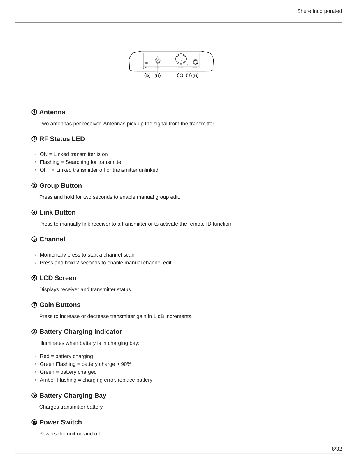
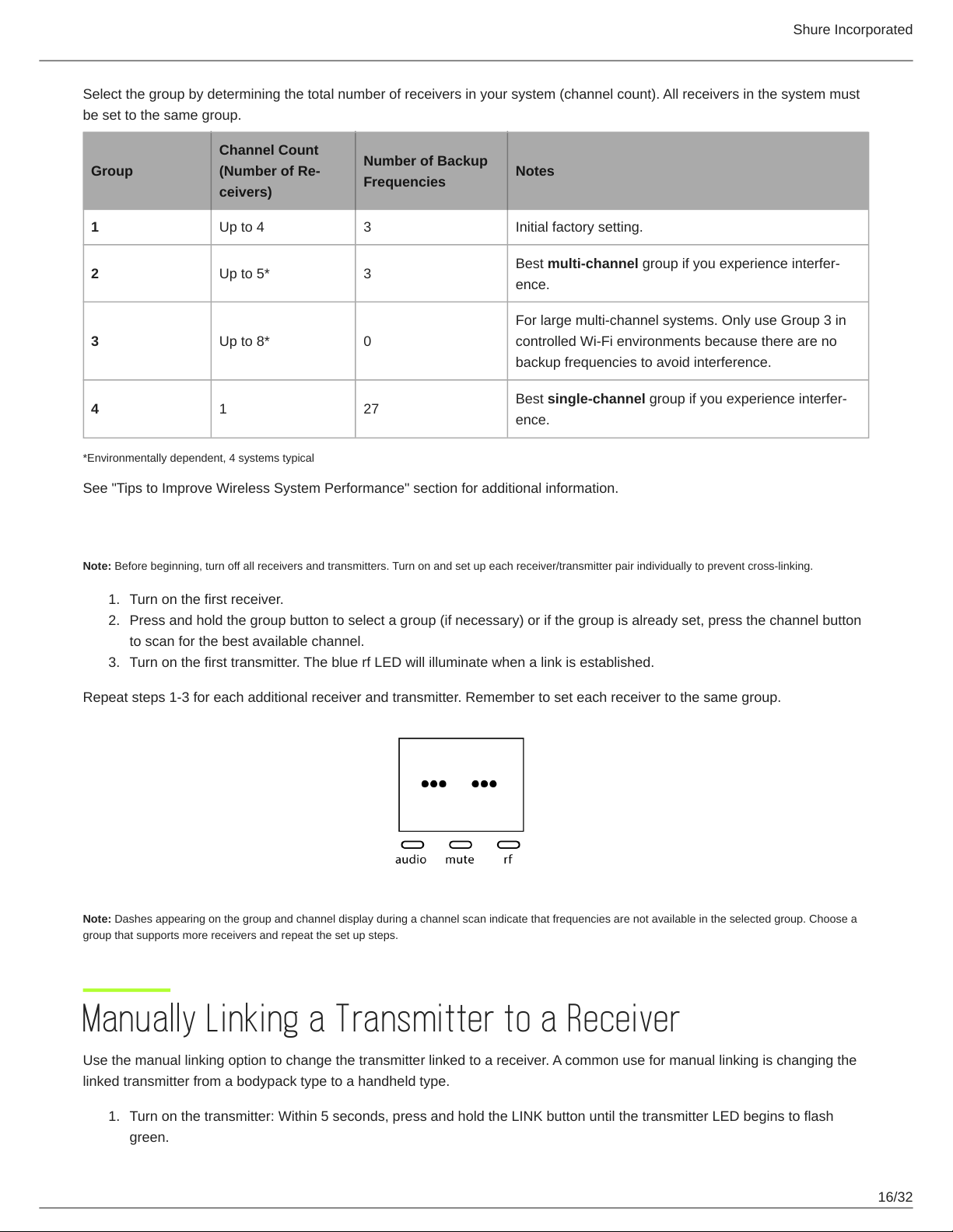
GLXD4 Receiver Controls and Connectors
Shure Incorporated
8/32
◦
◦
◦
◦
◦
◦
◦
◦
◦
① Antenna
Two antennas per receiver. Antennas pick up the signal from the transmitter.
② RF Status LED
ON = Linked transmitter is on
Flashing = Searching for transmitter
OFF = Linked transmitter off or transmitter unlinked
③ Group Button
Press and hold for two seconds to enable manual group edit.
④ Link Button
Press to manually link receiver to a transmitter or to activate the remote ID function
⑤ Channel
Momentary press to start a channel scan
Press and hold 2 seconds to enable manual channel edit
⑥ LCD Screen
Displays receiver and transmitter status.
⑦ Gain Buttons
Press to increase or decrease transmitter gain in 1 dB increments.
⑧ Battery Charging Indicator
Illuminates when battery is in charging bay:
Red = battery charging
Green Flashing = battery charge > 90%
Green = battery charged
Amber Flashing = charging error, replace battery
⑨ Battery Charging Bay
Charges transmitter battery.
⑩ Power Switch
Powers the unit on and off.
Shure Incorporated
9/32
◦
◦
◦
Note: The battery continues to charges even when the switch is off.
⑪ Power Supply Jack
Connect the supplied 15 V DC external power supply.
⑫ Mic Out
XLR microphone output jack supplies microphone-level audio output.
⑬ USB Port
For uploading firmware updates
⑭ Instr Out
TRS ¼" (6.35mm) audio output. Connect to mixers, recorders, and amplifiers.
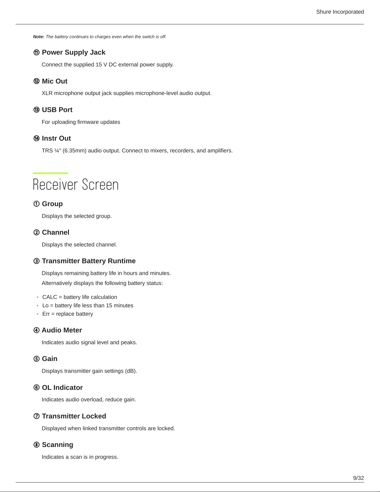
Receiver Screen
① Group
Displays the selected group.
② Channel
Displays the selected channel.
③ Transmitter Battery Runtime
Displays remaining battery life in hours and minutes.
Alternatively displays the following battery status:
CALC = battery life calculation
Lo = battery life less than 15 minutes
Err = replace battery
④ Audio Meter
Indicates audio signal level and peaks.
⑤ Gain
Displays transmitter gain settings (dB).
⑥ OL Indicator
Indicates audio overload, reduce gain.
⑦ Transmitter Locked
Displayed when linked transmitter controls are locked.
⑧ Scanning
Indicates a scan is in progress.
Shure Incorporated
10/32
◦
◦
⑨ Auto
Indicates that the selected group has backup channels available.
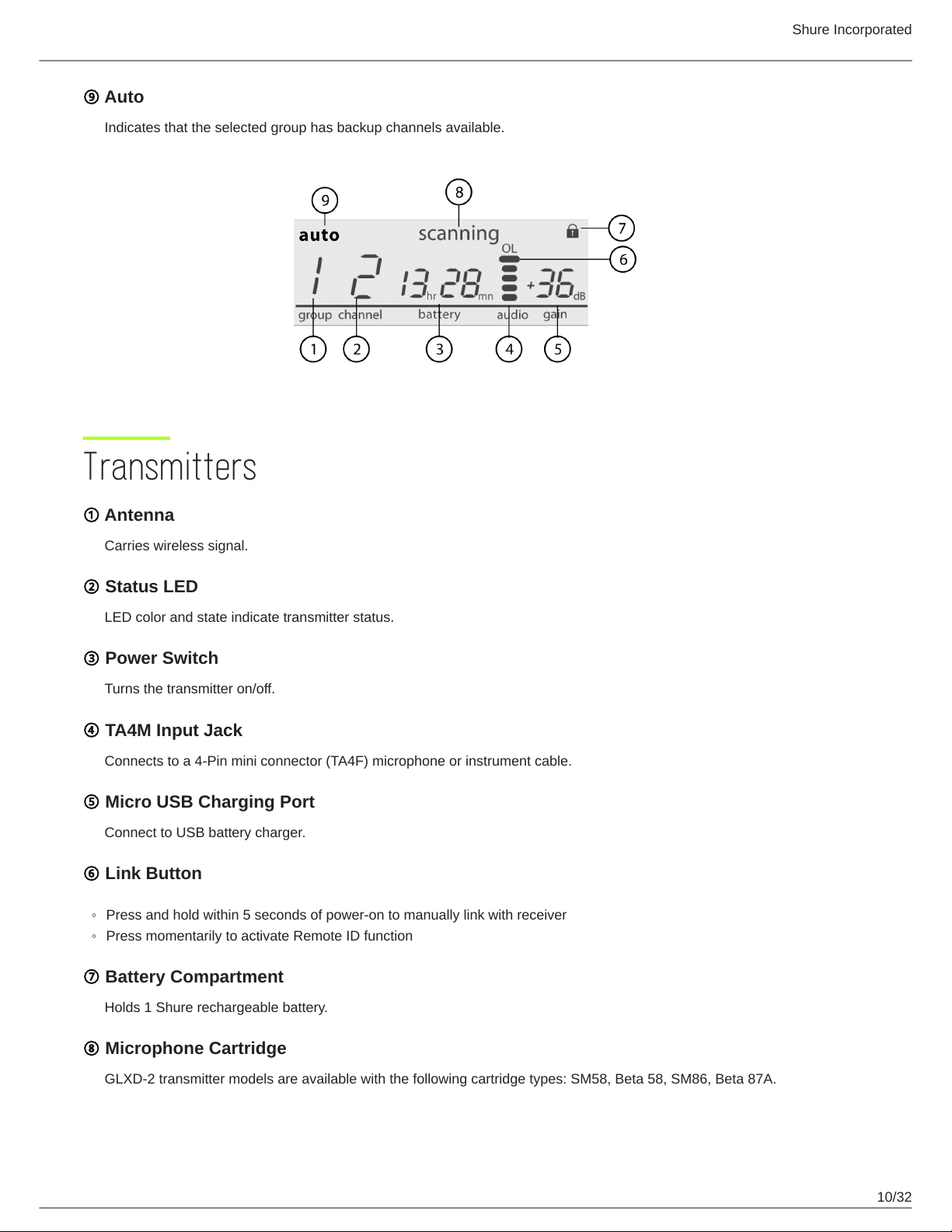
Transmitters
① Antenna
Carries wireless signal.
② Status LED
LED color and state indicate transmitter status.
③ Power Switch
Turns the transmitter on/off.
④ TA4M Input Jack
Connects to a 4-Pin mini connector (TA4F) microphone or instrument cable.
⑤ Micro USB Charging Port
Connect to USB battery charger.
⑥ Link Button
Press and hold within 5 seconds of power-on to manually link with receiver
Press momentarily to activate Remote ID function
⑦ Battery Compartment
Holds 1 Shure rechargeable battery.
⑧ Microphone Cartridge
GLXD-2 transmitter models are available with the following cartridge types: SM58, Beta 58, SM86, Beta 87A.
Shure Incorporated
11/32
Transmitter Status LED
LED is green during normal operation.
LED color or flashing indicates a change in transmitter status as shown in the following table:
Color State Status
Green
Flashing (slow) transmitter attempting relink with receiver
Flashing (fast) unlinked transmitter searching for receiver
Flashes 3 times indicates locked transmitter when power switch is pressed
Red
On battery life < 1 hour
Flashing battery life < 30 minutes
Red/Green Flashing remote ID active
Amber Flashing battery error, replace battery
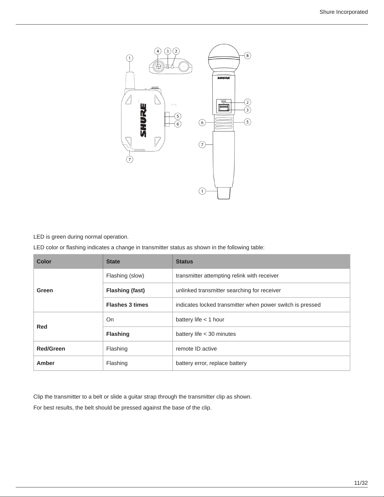
Wearing the Bodypack Transmitter
Clip the transmitter to a belt or slide a guitar strap through the transmitter clip as shown.
For best results, the belt should be pressed against the base of the clip.
Shure Incorporated
12/32
•
•
•
•
•
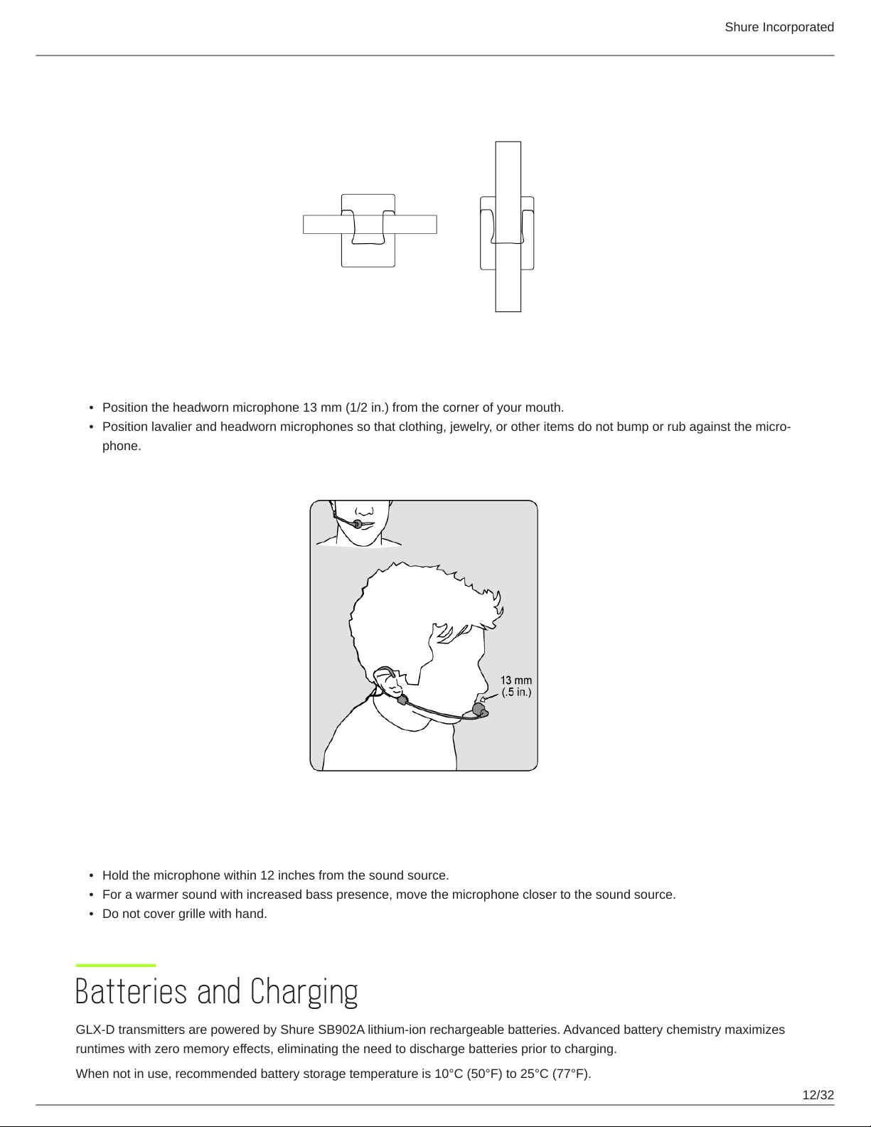
Wearing the Headworn Microphone
Position the headworn microphone 13 mm (1/2 in.) from the corner of your mouth.
Position lavalier and headworn microphones so that clothing, jewelry, or other items do not bump or rub against the micro
phone.
Correct Microphone Placement
Hold the microphone within 12 inches from the sound source.
For a warmer sound with increased bass presence, move the microphone closer to the sound source.
Do not cover grille with hand.
Batteries and Charging
GLX-D transmitters are powered by Shure SB902A lithium-ion rechargeable batteries. Advanced battery chemistry maximizes
runtimes with zero memory effects, eliminating the need to discharge batteries prior to charging.
When not in use, recommended battery storage temperature is 10°C (50°F) to 25°C (77°F).
Shure Incorporated
13/32
1.
2.
1.
2.
1.
2.
Note: The transmitter will not pass RF or audio signals when connected to the charging cable.
The following battery charging options are available:
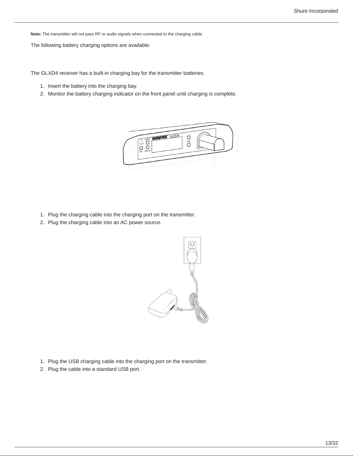
Receiver Charging Bay
The GLXD4 receiver has a built-in charging bay for the transmitter batteries.
Insert the battery into the charging bay.
Monitor the battery charging indicator on the front panel until charging is complete.
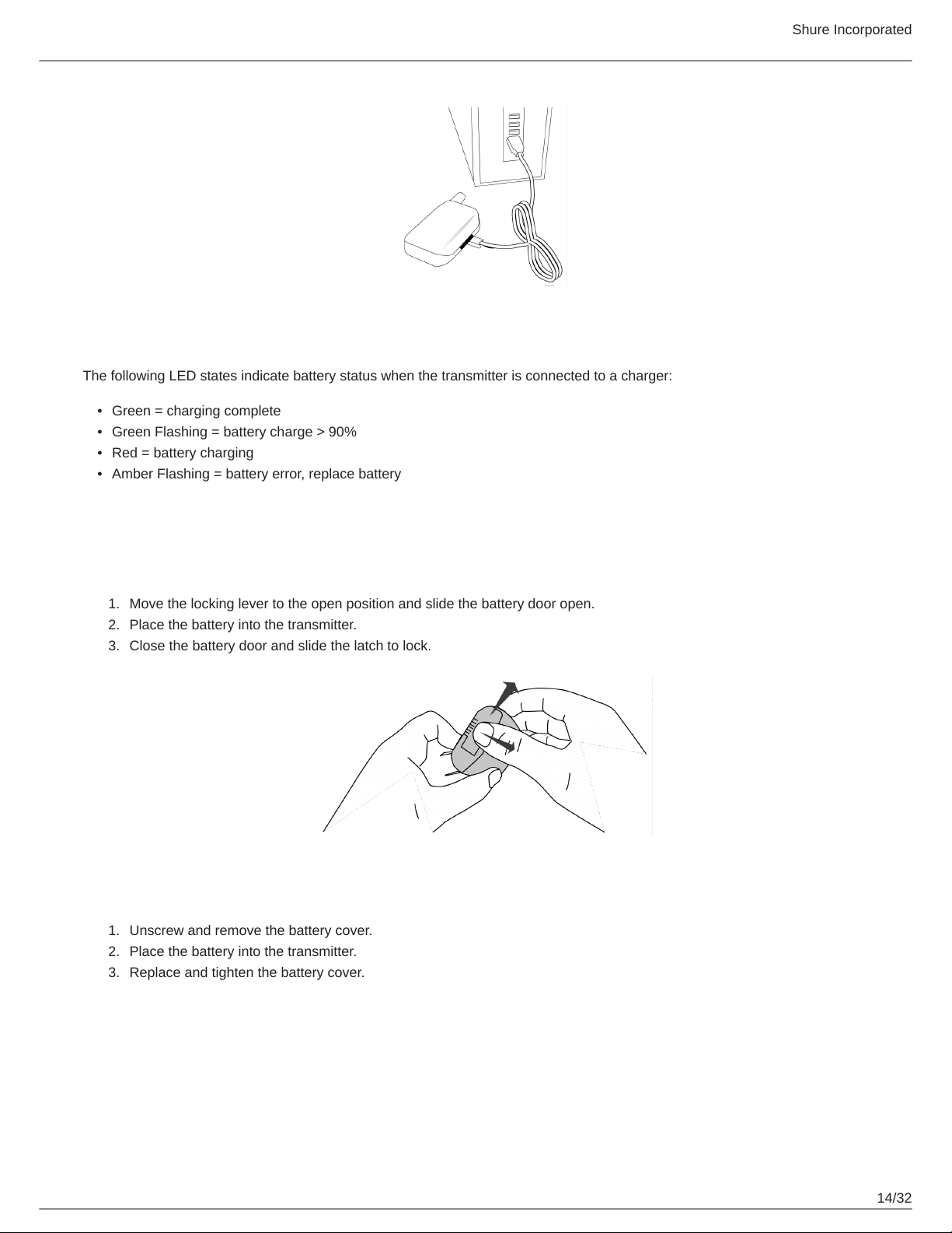
Charging from an AC Power Source
Plug the charging cable into the charging port on the transmitter.
Plug the charging cable into an AC power source.
Charging from a USB Port
Plug the USB charging cable into the charging port on the transmitter.
Plug the cable into a standard USB port.
Shure Incorporated
14/32
•
•
•
•
1.
2.
3.
1.
2.
3.
LED Status During Charging
The following LED states indicate battery status when the transmitter is connected to a charger:
Green = charging complete
Green Flashing = battery charge > 90%
Red = battery charging
Amber Flashing = battery error, replace battery
Installing Transmitter Batteries
Bodypack Transmitter
Move the locking lever to the open position and slide the battery door open.
Place the battery into the transmitter.
Close the battery door and slide the latch to lock.
Handheld Transmitter
Unscrew and remove the battery cover.
Place the battery into the transmitter.
Replace and tighten the battery cover.
Shure Incorporated
15/32
•
•
•
Charging Times and Transmitter Runtimes
Use the following table to determine approximate battery runtime based on the duration of charging time. Times shown are in
hours and minutes. GLX-D transmitters automatically power-off after approximately 1 hour to conserve battery life if the signal
from a linked receiver is not detected.
Receiver Bay or AC Power Source
Charging
USB Connection Charging Transmitter Runtime
0:15 0:30 up to 1:30
0:30 1:00 up to 3:00
1:00 2:00 up to 6:00
3:00 4:00 up to 11:30*
*Storage time or excessive heat will reduce maximum runtime.
Note: If receiver is powered off and remains plugged in, battery will continue charging.
Important Tips for Care and Storage of Shure Rechargeable Batteries
Proper care and storage of Shure batteries results in reliable performance and ensures a long lifetime.
Always store batteries and transmitters at room temperature
Ideally, batteries should be charged to approximately 40% of capacity for long-term storage
During storage, check batteries every 6 months and recharge to 40% of capacity as needed
Important: Always fully charge a new battery before first use, in receiver if possible.
Multiple Receiver Systems
For ease of set up, frequencies are divided into groups to best match the channel requirements for your system.
Shure Incorporated
16/32
1.
2.
3.
1.
Select the group by determining the total number of receivers in your system (channel count). All receivers in the system must
be set to the same group.
Group
Channel Count
(Number of Re
ceivers)
Number of Backup
Frequencies
Notes
1 Up to 4 3 Initial factory setting.
2 Up to 5* 3
Best multi-channel group if you experience interfer
ence.
3 Up to 8* 0
For large multi-channel systems. Only use Group 3 in
controlled Wi-Fi environments because there are no
backup frequencies to avoid interference.
4 1 27
Best single-channel group if you experience interfer
ence.
*Environmentally dependent, 4 systems typical
See "Tips to Improve Wireless System Performance" section for additional information.
Setting Up Receivers and Transmitters
Note: Before beginning, turn off all receivers and transmitters. Turn on and set up each receiver/transmitter pair individually to prevent cross-linking.
Turn on the first receiver.
Press and hold the group button to select a group (if necessary) or if the group is already set, press the channel button
to scan for the best available channel.
Turn on the first transmitter. The blue rf LED will illuminate when a link is established.
Repeat steps 1-3 for each additional receiver and transmitter. Remember to set each receiver to the same group.
Note: Dashes appearing on the group and channel display during a channel scan indicate that frequencies are not available in the selected group. Choose a
group that supports more receivers and repeat the set up steps.
Manually Linking a Transmitter to a Receiver
Use the manual linking option to change the transmitter linked to a receiver. A common use for manual linking is changing the
linked transmitter from a bodypack type to a handheld type.
Turn on the transmitter: Within 5 seconds, press and hold the LINK button until the transmitter LED begins to flash
green.
Shure Incorporated
17/32
2.
3.
1.
2.
3.
•
•
•
•
Press and hold the link button on the receiver: The blue rf LED will flash, and then remain on when the link has been
established.
Test the audio to verify the link and adjust the gain if necessary.
Combo Systems
A combo system is created by linking two transmitters to a single receiver. Only one transmitter can be active at a time to pre
vent cross interference. Gain settings for each transmitter can be independently set and stored when the transmitter is active.
Important! Do not turn on and operate both linked transmitters at any time.
Turn off both transmitters before beginning.
Press the group button to select a group. The receiver automatically scans the selected group to find the best available
channel.
Turn on transmitter 1 and link it to the receiver. Adjust the gain, and then turn off the transmitter.
Turn on transmitter 2 and link it to the receiver. Adjust the gain, and then turn off the transmitter.
2.4 GHz Spectrum Overview
GLX-D operates within the 2.4GHz ISM band which is utilized by Wi-Fi, Bluetooth, and other wireless devices. The benefit of
2.4GHz is that it’s a global band that can be used anywhere in the world, license free.
Overcoming the Challenges of 2.4GHz
The challenge of 2.4GHz is that Wi-Fi traffic can be unpredictable. GLX-D meets these challenges in the following ways:
Prioritizes and transmits on the best 3 frequencies per channel (choosing from a pool of 6 frequencies across the 2.4GHz
band)
Repeats the most important information such that one frequency can be taken out entirely without audio interruption
Continuously scans during usage to rank all frequencies (both current and backup frequencies)
Seamlessly moves away from interference to backup frequencies without audio interruption
Coexisting with Wi-Fi
If you plan to use WiFi during a performance, turn on WiFi devices prior to turning on GLXD and scanning for the best chan
nel. GLXD detects and avoids other WiFi traffic by scanning the entire 2.4GHz environment and selecting the 3 best frequen
cies to transmit on. The result of this is reliable performance for your GLXD wireless system as well as avoiding WiFi trans
missions which may be important as well.
“Bursting” WiFi is harder to detect as it is periodic; however, because GLXD repeats the most important information, even
bursts at very highlevels don’t have an effect on your audio performance.
Challenging Wireless Environments
Some environments are more difficult than others for 2.4 GHz wireless system performance. Additionally, body absorption has
a greater impact in the 2.4 GHz spectrum, compared to the UHF spectrum. The simplest solution in many cases is to reduce
the transmitter to receiver distance such as placing the receivers on the stage with a clear line of sight.
Shure Incorporated
18/32
•
◦
◦
•
•
•
•
•
•
◦
◦
•
•
◦
•
•
•
•
•
•
•
•
◦
◦
◦
Challenging environments include:
Areas with few reflective surfaces such as:
Outdoors
Buildings with very high ceilings
3 or more GLX-D receivers in use
Strong Wi-Fi presence
Competitive 2.4 GHz systems in use
Note: Unlike analog TV band wireless which typically uses the same type of transmissions across manufacturers, all 2.4GHz wireless currently on the market
use different variations of wireless transmission. These differences make it more difficult to mix and match 2.4 GHz from multiple manufacturers successfully,
as can be done with TV band wireless solutions.
Tips and Methods to Improve Wireless System Perfor-
mance
If you encounter interference or dropouts, try the following suggestions:
Scan for the best available channel (press the channel button).
Reduce transmitter to receiver distance for example, place receivers on stage with a line of sight to the front of the re
ceiver.
Change the group for all GLX-D systems:
Single-Chanel System: use Group 4, which is optimized for single-channel use
Multi-Channel System: use Group 2, which is the most robust wireless group
Move receiver further away from WiFi access points, computers, or other active 2.4 GHz sources. Recommended dis
tance is a minimum of 3 meters (10 feet).
Disable non-critical Wi-Fi on computers, cell phones, and other portable devices
If you plan to use WiFi during a performance, turn on WiFi prior to turning on GLXD and scanning for the best chan
nel.
Keep the transmitter and receiver more than 2 meters (6 feet) apart
Avoid heavy Wi-Fi traffic activities such as downloading large files or viewing a movie.
Locate competitive 2.4 GHz receivers away from each other
Avoid placing transmitter and receiver where metal or other dense materials may be present
Move the receiver to the top of the equipment rack
Keep transmitters more than 2 meters (6 feet) apart - this is less critical at shorter receiver to transmitter distances
Note: If transmitters are within 6 inches of non-GLXD transmitters or microphone cartridges, audible noise is possible.
During sound check, mark trouble spots and ask presenters or performers to avoid those areas
If there is a known strong source of Wi-Fi and you specifically want to use frequencies within that Wi-Fi channel, use the
following Group/Channel of GLX-D (best option listed first):
Wi-Fi 1: Group 3/Channel 8, Group 3/Channel 4
Wi-Fi 6: Group 3/Channel 7, Group 3/Channel 5
Wi-Fi 11: Group 3/Channel 2, Group 3/Channel 1
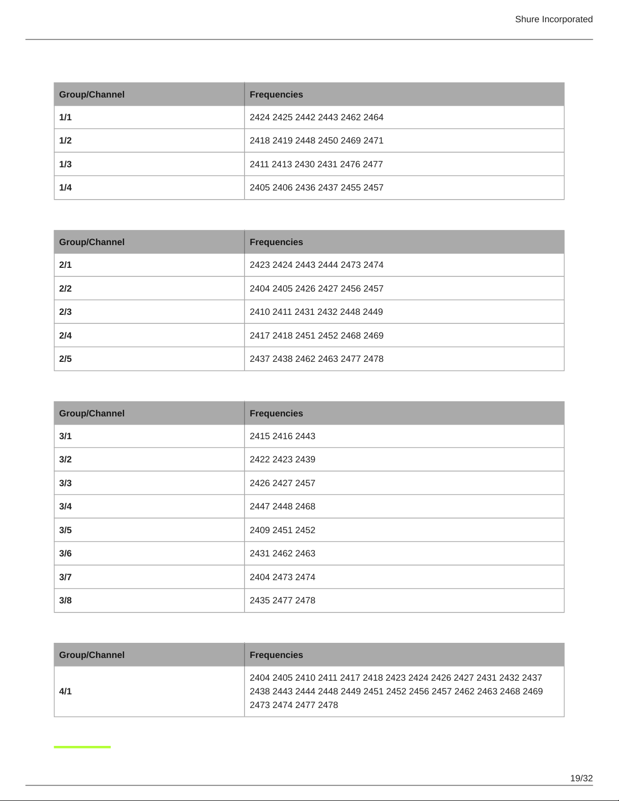
2.4 GHz Frequency Tables
The following tables list receiver channels, frequencies, and latency for each group:
Shure Incorporated
19/32
Group 1: Channels 1-4 (latency = 4.0 ms)
Group/Channel Frequencies
1/1 2424 2425 2442 2443 2462 2464
1/2 2418 2419 2448 2450 2469 2471
1/3 2411 2413 2430 2431 2476 2477
1/4 2405 2406 2436 2437 2455 2457
Group 2: Channels 1-5 (latency = 7.3 ms)
Group/Channel Frequencies
2/1 2423 2424 2443 2444 2473 2474
2/2 2404 2405 2426 2427 2456 2457
2/3 2410 2411 2431 2432 2448 2449
2/4 2417 2418 2451 2452 2468 2469
2/5 2437 2438 2462 2463 2477 2478
Group 3: Channels 1-8 (latency = 7.3 ms)
Group/Channel Frequencies
3/1 2415 2416 2443
3/2 2422 2423 2439
3/3 2426 2427 2457
3/4 2447 2448 2468
3/5 2409 2451 2452
3/6 2431 2462 2463
3/7 2404 2473 2474
3/8 2435 2477 2478
Group 4: Channel 1 (latency = 7.3 ms)
Group/Channel Frequencies
4/1
2404 2405 2410 2411 2417 2418 2423 2424 2426 2427 2431 2432 2437
2438 2443 2444 2448 2449 2451 2452 2456 2457 2462 2463 2468 2469
2473 2474 2477 2478
Shure Incorporated
20/32
•
•
Firmware
Firmware is embedded software in each component that controls functionality. Periodically, new versions of firmware are devel
oped to incorporate additional features and enhancements. To take advantage of design improvements, new versions of the
firmware can be downloaded and installed using the Shure Update Utility tool.
Software is available for download from http://www.shure.com/update-utility.
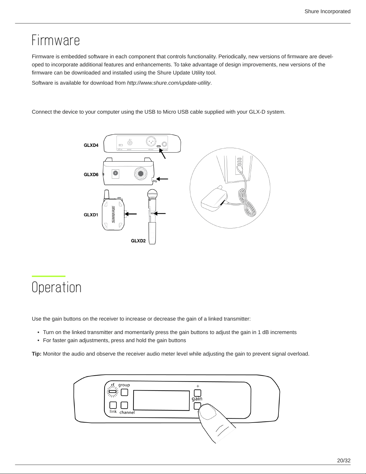
Connect to the Computer
Connect the device to your computer using the USB to Micro USB cable supplied with your GLX-D system.
Operation
Gain Adjustment
Use the gain buttons on the receiver to increase or decrease the gain of a linked transmitter:
Turn on the linked transmitter and momentarily press the gain buttons to adjust the gain in 1 dB increments
For faster gain adjustments, press and hold the gain buttons
Tip: Monitor the audio and observe the receiver audio meter level while adjusting the gain to prevent signal overload.
Shure Incorporated
21/32
•
•
1.
2.
3.
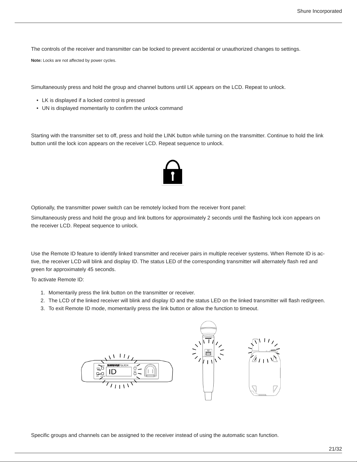
Locking and Unlocking the Controls
The controls of the receiver and transmitter can be locked to prevent accidental or unauthorized changes to settings.
Note: Locks are not affected by power cycles.
Locking the Receiver Controls
Simultaneously press and hold the group and channel buttons until LK appears on the LCD. Repeat to unlock.
LK is displayed if a locked control is pressed
UN is displayed momentarily to confirm the unlock command
Locking the Transmitter Power Switch
Starting with the transmitter set to off, press and hold the LINK button while turning on the transmitter. Continue to hold the link
button until the lock icon appears on the receiver LCD. Repeat sequence to unlock.
Optionally, the transmitter power switch can be remotely locked from the receiver front panel:
Simultaneously press and hold the group and link buttons for approximately 2 seconds until the flashing lock icon appears on
the receiver LCD. Repeat sequence to unlock.
Identifying Linked Transmitters and Receivers with Remote ID
Use the Remote ID feature to identify linked transmitter and receiver pairs in multiple receiver systems. When Remote ID is ac
tive, the receiver LCD will blink and display ID. The status LED of the corresponding transmitter will alternately flash red and
green for approximately 45 seconds.
To activate Remote ID:
Momentarily press the link button on the transmitter or receiver.
The LCD of the linked receiver will blink and display ID and the status LED on the linked transmitter will flash red/green.
To exit Remote ID mode, momentarily press the link button or allow the function to timeout.
Manually Selecting a Group and Channel
Specific groups and channels can be assigned to the receiver instead of using the automatic scan function.
Shure Incorporated
22/32
1.
2.
3.
1.
2.
3.
Note: Group 3 should only be used in controlled Wi-Fi environments to prevent interference from unexpected Wi-Fi devices.
Selecting a Group
Press and hold the group button for 2 seconds until the group display flashes.
Press the group button to scroll through the available groups.
The receiver will automatically save the selected group.
Selecting a Channel
Press and hold the channel button for 2 seconds until the channel display flashes.
Press the channel button to scroll through the available channels.
The receiver will automatically save the selected channel.
Note: A double dash symbol-- displayed on the receiver screen during a channel scan indicates that there are no available channels within the selected group.
Choose a group with more channels and repeat set up steps.
Troubleshooting
Issue Indicator Status Solution
No sound or faint sound
Receiver RF LED on
Verify all sound system connections or ad
just gain as needed (see Adjusting Gain).
Verify that the receiver is connected to mix
er/amplifier.
Receiver RF LED off
Turn on transmitter.
Make sure the batteries are installed correct
ly.
Link transmitter and receiver (see Linking
topic).
Charge or change transmitter battery.
Receiver LCD screen
off
Make sure AC adapter is securely plugged
into electrical outlet.
Make sure receiver is powered on.
Transmitter indicator
LED flashing red
Charge or change transmitter battery.
Transmitter plugged
into charger.
Disconnect transmitter from charger.
Audio artifacts or dropouts rf LED flickering or off
Change receiver and transmitter to a differ
ent group and/or channel.
Shure Incorporated
23/32
Issue Indicator Status Solution
Identify nearby sources of interference (cell
phones, WiFi access points, signal proces
sor, etc...) and shutdown or remove source.
Charge or change transmitter battery.
Ensure that receiver and transmitter are po
sitioned within system parameters.
System must be set up within recommended
range and receiver kept away from metallic
surfaces.
Transmitter must be used in line of sight
from receiver for optimal sound.
Distortion
OL indicator appears on
receiver LCD
Reduce transmitter gain (see Gain Adjust
ment).
Transmitter and receiver link unsuccessful
Transmitter and receiver
LEDs flash to indicate
that linking started, but
the link fails
Update both components to firmware ver
sion 2.0 or greater. Download the Shure Up
date Utility application and follow the instruc
tions.
Sound level variations when switching to dif
ferent sources
N/A
Adjust transmitter gain as necessary (see
Gain Adjustment).
Receiver/transmitter won't turn off
Transmitter LED flash
ing rapidly
Controls locked. See Locking and Unlocking
Controls.
Receiver gain control cannot be adjusted N/A
Check transmitter. Transmitter must be on to
enable gain changes.
Receiver controls cannot be adjusted
LK shown on receiver
display when buttons
are pressed
Controls locked. See Locking and Unlocking
Controls.
Transmitter ID function does not respond
Transmitter LED flashes
green 3 times
Controls locked. See Locking and Unlocking
Controls.
Transmitter information does not appear on
the Receiver LCD
N/A
Linked transmitter is off or the receiver is not
linked to a transmitter.
Transmitter powers off after 1 hour
Transmitter status LED
off
GLX-D transmitters automatically power-off
after 1 hour to conserve battery life if the sig
nal from a linked receiver is not detected.
Make sure that linked receiver is turned on.
SB902A battery will not charge in GLXD1
bodypack transmitter
Rapid flashing green
LED on GLXD1
Charge battery once in GLXD4 receiver.
Subsequent recharging can occur in GLXD1
bodypack.
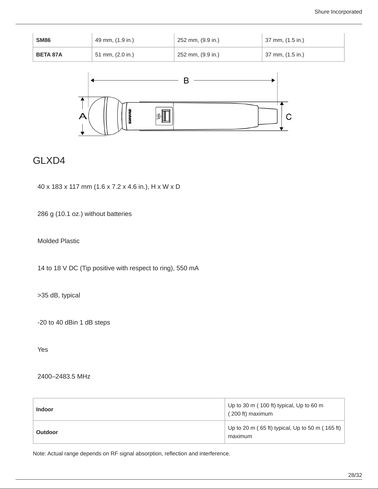
Model A B C
SM58 51 mm, 2.0 in. 252 mm, 9.9 in. 37 mm, 1.5 in.
BETA 58 51 mm, 2.0 in. 252 mm, 9.9 in. 37 mm, 1.5 in.
Shure Incorporated
24/32
•
•
•
Model A B C
SM86 49 mm, 1.9 in. 252 mm, 9.9 in. 37 mm, 1.5 in.
BETA 87A 51 mm, 2.0 in. 252 mm, 9.9 in. 37 mm, 1.5 in.
Resetting Components
Use the reset function if it is necessary to restore the transmitter or receiver to their factory settings.
Resetting the Receiver
Restores the receiver to the following factory settings:
Gain level = default
Controls = unlocked
Press and hold the link button while turning on the receiver power until the LCD displays RE.
Note: When reset is complete, the receiver will automatically initiate linking to search for a transmitter. Press and hold the transmitter link button within five
seconds of powering-on to complete the link.
Resetting the Transmitter
Restores the transmitter to the following factory settings:
Controls = unlocked
Press and hold the transmitter link button while turning on the transmitter until power LED goes off.
When the link button is released, the transmitter will automatically initiate linking to find an available receiver. Press the link but
ton on an available receiver to relink.
Specifications
Tuning Bandwidth
2400–2483.5 MHz
Working Range
Indoor
Up to 30 m ( 100 ft) typical, Up to 60 m
( 200 ft) maximum
Outdoor
Up to 20 m ( 65 ft) typical, Up to 50 m ( 165 ft)
maximum
Note: Actual range depends on RF signal absorption, reflection and interference.Note: Actual range depends on RF signal ab
sorption, reflection and interference.
Transmit Mode
Shure proprietary digital
Shure Incorporated
25/32
Audio Frequency Response
20 Hz– 20 kHz
Dynamic Range
120 dB, Aweighted
RF Sensitivity
88 dBm, typical
Total Harmonic Distortion
0.2%, typical
RF Output Power
10 mW E.I.R.P. max
Operating Temperature Range
-18°C (0°F) to 57°C (135°F)
Note: Battery characteristics may limit this range.
Storage Temperature Range
-29°C (-20°F) to 74°C (165°F)
Polarity
Positive voltage applied to the tip of the guitar cable phone plug produces positive voltage at the tip of the
high impedance ¼-inch output.
Battery Life
Up to 11.5 hours
Guitar Tuner
Tuning Accuracy ±1 cent
Tuning Range F#0 to C8
Channel Count
4 typical, Up to 8 maximum
GLXD1
Dimensions
90 x 65 x 23 mm ( 3.56 x 2.54 x 0.90 in.), H x W x D (without antenna)
Weight
132 g (4.7 oz.) without batteries
Power Requirements
3.7 V Rechargeable LiIon
Shure Incorporated
26/32
Housing
Cast Metal, Black Powdercoat
Input Impedance
900 kΩ
RF Output Power
10 mW E.I.R.P. max
Transmitter Input
Connector
4-Pin male mini connector (TA4M)
Configuration
Unbalanced
Maximum Input Level
1 kHz at 1% THD
+8.4 dBV (7.5 Vpp)
Antenna Type
Internal Monopole
Pin Assignments
TA4M
1 ground (cable shield)
2 + 5 V Bias
3 audio
4
Tied through active load to ground (On in
strument adapter cable, pin 4 floats)
Pin Assignments
TA4M
1 ground (cable shield)
2 + 5 V Bias
3 audio
4 Tied through active load to ground (On instrument adapter cable, pin 4 floats)

Shure Incorporated
27/32
Weight
SM58 267 g (9.4 oz.) without batteries
BETA 58 221 g (7.8 oz.) without batteries
SM86 275 g (9.1 oz.) without batteries
BETA 87A 264 g (9.3 oz.) without batteries
Housing
Molded Plastic
Power Requirements
3.7 V Rechargeable LiIon
RF Output Power
10 mW E.I.R.P. max
Maximum Input Level
SM58 146 dB SPL
BETA 58 147 dB SPL
SM86 143 dB SPL
BETA 87A 147 dB SPL
Dimensions
Model A B C
SM58 51 mm, (2.0 in.) 252 mm, (9.9 in.) 37 mm, (1.5 in.)
BETA 58 51 mm, (2.0 in.) 252 mm, (9.9 in.) 37 mm, (1.5 in.)
Shure Incorporated
28/32
SM86 49 mm, (1.9 in.) 252 mm, (9.9 in.) 37 mm, (1.5 in.)
BETA 87A 51 mm, (2.0 in.) 252 mm, (9.9 in.) 37 mm, (1.5 in.)
GLXD4
Dimensions
40 x 183 x 117 mm (1.6 x 7.2 x 4.6 in.), H x W x D
Weight
286 g (10.1 oz.) without batteries
Housing
Molded Plastic
Power Requirements
14 to 18 V DC (Tip positive with respect to ring), 550 mA
Spurious Rejection
>35 dB, typical
Gain Adjustment Range
20 to 40 dBin 1 dB steps
Phantom Power Protection
Yes
Tuning Bandwidth
2400–2483.5 MHz
Working Range
Indoor
Up to 30 m ( 100 ft) typical, Up to 60 m
( 200 ft) maximum
Outdoor
Up to 20 m ( 65 ft) typical, Up to 50 m ( 165 ft)
maximum
Note: Actual range depends on RF signal absorption, reflection and interference.
Shure Incorporated
29/32
Transmit Mode
Frequency Hopping
Audio Frequency Response
20 Hz– 20 kHz
Note: Dependent on microphone type
Dynamic Range
120 dB, Aweighted
RF Sensitivity
88 dBm, typical
Total Harmonic Distortion
0.2%, typical
RF Output Power
10 mW E.I.R.P. max
Operating Temperature Range
-18°C (0°F) to 57°C (135°F)
Note: Battery characteristics may limit this range.
Storage Temperature Range
-29°C (-20°F) to 74°C (165°F)
Polarity
Positive pressure on microphone diaphragm (or positive voltage applied to tip of WA302 phone plug) pro
duces positive voltage on pin 2 (with respect to pin 3 of lowimpedance output) and the tip of the high im
pedance 1/4-inch output.
Battery Life
Up to 16 hours
Channel Count
4 typical, Up to 8 maximum
Audio Output
Configuration
XLR Output Impedance balanced
6.35 mm (1/4") output Impedance balanced
Impedance
XLR Output 100 Ω
Shure Incorporated
30/32
1.
2.
1.
2.
6.35 mm (1/4") output 100 Ω(50 Ω, Unbalanced)
Maximum Audio Output Level
XLR connector (into 600 Ω load) +1 dBV
6.35 mm (1/4") connector (into 3 kΩ load) +8.5 dBV
Pin Assignments
XLR Output 1=ground, 2=hot, 3=cold
6.35 mm (1/4") connector Tip=audio, Ring=no audio, Sleeve=ground
Receiver Antenna Input
Impedance
50 Ω
Antenna Type
½ Wave Sleeve Dipole, non-removable
Maximum Input Level
−20 dBm
Certifications
This device complies with Part 15 of the FCC Rules. Operation is subject to the following two conditions: (1) this device may
not cause harmful interference, and (2) this device must accept any interference received, including interference that may
cause undesired operation.
This wireless system operates in the globally available ISM band 2400 MHz to 2483.5 MHz. The operation does not require a
user license.
Certified by ISED in Canada under RSS-210 and RSS-GEN.
IC: 616A-GLXD1, 616A-GLXD2, 616A-GLXD4
Certified under FCC Part 15.
FCC ID: DD4GLXD1, DD4GLXD2, DD4GLXD4
Industry Canada ICES-003 Compliance Label: CAN ICES-3 (B)/NMB-3(B)
This device contains licenceexempt transmitter(s)/receiver(s) that comply with Innovation, Science and Economic Develop
ment Canada’s licenceexempt RSS(s). Operation is subject to the following two conditions:
This device may not cause interference.
This device must accept any interference, including interference that may cause undesired operation of the device.
L’émetteur/récepteur exempt de licence contenu dans le présent appareil est conforme aux CNR d’Innovation, Sciences et
Développement économique Canada applicables aux appareils radio exempts de licence. L’exploitation est autorisée aux deux
conditions suivantes :
L’appareil ne doit pas produire de brouillage;
L’appareil doit accepter tout brouillage radioélectrique subi, même si le brouillage est susceptible d’en compromettre le
fonctionnement.
Shure Incorporated
31/32
•
•
1.
2.
3.
Meets essential requirements of the following European Directives:
WEEE Directive 2012/19/EU, as amended by 2008/34/EC
RoHS Directive EU 2015/863
Note: Please follow your regional recycling scheme for batteries and electronic waste
This product meets the Essential Requirements of all relevant European directives and is eligible for CE marking.
CE Notice:
Hereby, Shure Incorporated declares that this product with CE Marking has been determined to be in compliance with Euro
pean Union requirements. The full text of the EU declaration of conformity is available at the following site: https://
www.shure.com/en-EU/support/declarations-of-conformity.
Authorized European Importer / Representative:
Shure Europe GmbH
Department: Global Compliance
Jakob-Dieffenbacher-Str. 12
75031 Eppingen, Germany
Phone: +49-7262-92 49 0
Fax: +49-7262-92 49 11 4
Email: [email protected]
運用に際しての注意
この機器の使用周波数帯では、電子レンジ等の産業・科学・医療用機器のほか工場の製造ライン等で使用されている移動体識別用の
構内無線局(免許を要する無線局)及び特定小電力無線局(免許を要しない無線局)並びにアマチュア無線局(免許を要する無
線局)が運用されています。
この機器を使用する前に、近くで移動体識別用の構内無線局及び特定小電力無線局並びにアマ チュア無線局が運用さ
れていないことを確認して下さい。
万一、この機器から移動体識別用の構内無線局に対して有害な電波干渉の事例が発生した場合には、 速やかに使用周波
数を変更するか又は電波の発射を停止した上、下記連絡先にご連絡頂き、混 信回避のための処置等(例えば、パーティ
ションの設置など)についてご相談して下さい。
その他、この機器から移動体識別用の特定小電力無線局あるいはアマチュア無線局に対して有害な電波干渉の事例が発生
した場合など何かお困りのことが起きたときは、保証書に記載の販売代 理店または購入店へお問い合わせください。代
理店および販売店情報は Shure 日本語ウェブサイト http://www.shure.co.jp でもご覧いただけます。
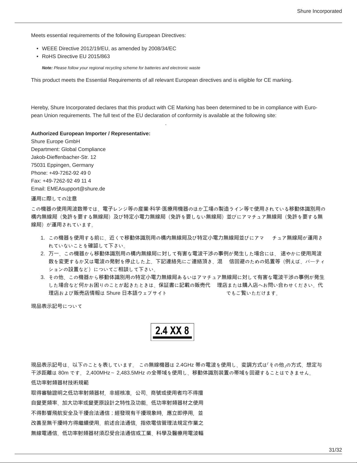
現品表示記号について
現品表示記号は、以下のことを表しています。 この無線機器は 2.4GHz 帯の電波を使用し、変調方式は「その他」の方式、想定与
干渉距離は 80m です。 2,400MHz~ 2,483.5MHz の全帯域を使用し、移動体識別装置の帯域を回避することはできません。
低功率射頻器材技術規範
取得審驗證明之低功率射頻器材,非經核准,公司、商號或使用者均不得擅
自變更頻率、加大功率或變更原設計之特性及功能。低功率射頻器材之使用
不得影響飛航安全及干擾合法通信;經發現有干擾現象時,應立即停用,並
改善至無干擾時方得繼續使用。前述合法通信,指依電信管理法規定作業之
無線電通信。低功率射頻器材須忍受合法通信或工業、科學及醫療用電波輻
Shure Incorporated
32/32
•
•
•
•
1.
2.
射性電機設備之干擾。
Information to the user
This equipment has been tested and found to comply with the limits for a Class B digital device, pursuant to part 15 of the FCC
Rules. This equipment generates, uses, and can radiate radio frequency energy and, if not installed and used in accordance
with the manufacturer's instruction manual, may cause interference with radio and television reception.
Notice: The FCC regulations provide that changes or modifications not expressly approved by Shure Incorporated could void
your authority to operate this equipment.
These limits are designed to provide reasonable protection against harmful interference in a residential installation. This equip
ment generates uses and can radiate radio frequency energy and, if not installed and used in accordance with the instructions,
may cause harmful interference to radio communications. However, there is no guarantee that interference will not occur in a
particular installation. If this equipment does cause harmful interference to radio or television reception, which can be deter
mined by turning the equipment off and on, the user is encouraged to try to correct the interference by one or more of the fol
lowing measures:
Reorient or relocate the receiving antenna.
Increase the separation between the equipment and the receiver.
Connect the equipment to an outlet on a circuit different from that to which the receiver is connected.
Consult the dealer or an experienced radio/TV technician for help.
This device complies with part 15 of the FCC Rules. Operation is subject to the following two conditions:
This device may not cause harmful interference.
This device must accept any interference received, including interference that may cause undesired operation.