Loading ...
Loading ...
Loading ...
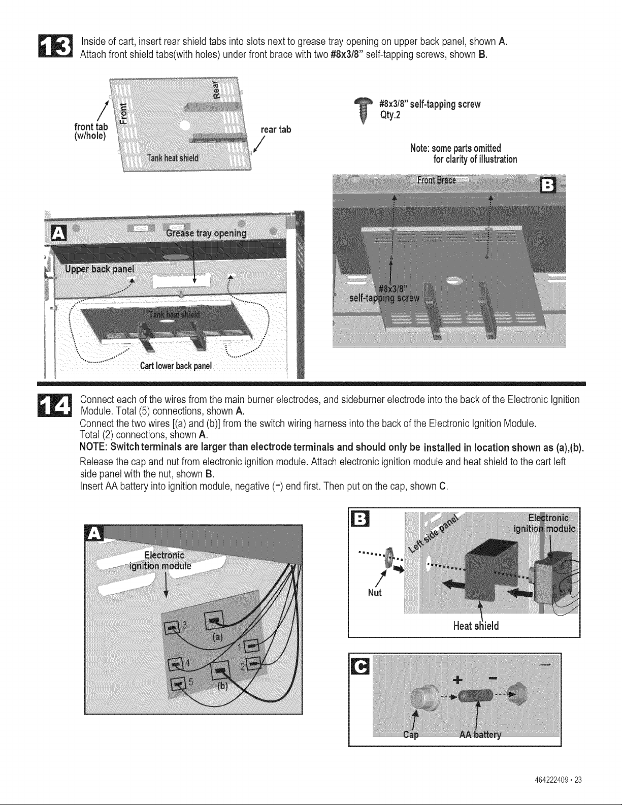
Inside of cart, insert rear shield tabs into slots next to grease tray opening on upper back panel, shown A.
Attach front shield tabs(with holes) under front brace with two #8x3/8" self-tapping screws, shown B.
front tab reartab
(w/hole)
#8x3/8"self-tappingscrew
Qty.2
Note:somepartsomitted
for clarityof illustration
y:
Cartlowerbackpanel
Connect each of the wires from the main burner electrodes, and sideburner electrode into the back of the Electronic Ignition
Module. Total (5) connections, shown A.
Connect the two wires [(a) and (b)] from the switch wiring harness into the back of the Electronic Ignition Module.
Total (2) connections, shown A.
NOTE: Switchterminals are larger than electrode terminals and should only be installed in location shown as (a),(b).
Release the cap and nut from electronic ignition module. Attach electronic ignition module and heat shield to the cart left
side panel with the nut, shown B.
Insert AA battery into ignition module, negative (=) end first. Then put on the cap, shown C.
!
Nut
Heatsllield
464222409,23
Loading ...
Loading ...
Loading ...