Page 1
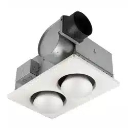
MODELS 765H110LB • 765H110L
VENTILATION FAN
WITH HEATER & LIGHT
READ AND SAVE THESE INSTRUCTIONS
IMPORTANT INSTRUCTIONS
READ ALL INSTRUCTIONS BEFORE INSTALLING OR
USING THIS HEATER.
To reduce the risk of fire, electric shock, or injury to persons, observe the
following:
1. Use this unit only in the manner intended by the manufacturer. If you have
questions, contact the manufacturer at the address or telephone number
listed in the warranty.
2. Before servicing or cleaning unit, switch power off at service panel and
lock the service disconnecting means to prevent power from being
switched on accidentally. When the service disconnecting means cannot
be locked, securely fasten a prominent warning device, such as a tag, to
the service panel.
3. Installation work and electrical wiring must be done by a qualified
person(s) in accordance with all applicable codes and standards, includ-
ing fire-rated construction codes and standards.
4. When cutting or drilling into wall or ceiling, do not damage electrical wiring
and other hidden utilities.
5. This heater is hot when in use. To avoid burns, do not let bare skin touch
hot surfaces. Keep combustible materials, such as furniture, pillows, bed-
ding, papers, clothes, etc. and curtains at least 3 feet (0.9 m) from the
front of the heater.
6. Extreme caution is necessary when any heater is used by or near chil-
dren or invalids and whenever the heater is left operating and unattended.
7. Do not operate any heater after it malfunctions. Disconnect power at ser-
vice panel and have heater inspected by a reputable electrician before
reusing.
8. Do not use outdoors.
9. To disconnect heater, turn controls to off, and turn off power to heater
circuit at main disconnect panel (or operate internal disconnect switch, if
provided).
10. Do not insert or allow foreign objects to enter any ventilation or exhaust
opening, as this may cause an electric shock or fire, or damage the heat-
er.
11. To prevent a possible fire, do not block air intakes or exhaust in any man-
ner.
12. A heater has hot and arcing or sparking parts inside. Do not use it in
areas where gasoline, paint, or flammable vapors or liquids are used or
stored.
13. Use this heater only as described in this manual. Any other use not rec-
ommended by the manufacturer may cause fire, electric shock, or injury
to persons.
14. This product must be grounded.
15. Do not install heater in a tub or shower enclosure.
16. THIS PRODUCT MUST BE MOUNTED IN A FLAT CEILING ONLY. In-
stallations in ceilings 9-feet high or less will provide maximum comfort.
DO NOT MOUNT THIS PRODUCT IN A WALL.
17. Install heater in ceiling only - at least 6 inches from any wall.
18. Do not connect heater to dimmer switch or speed control.
19. Provide a separate 20 AMP circuit. Use 12 GA. power cable of type which
meets code. Use supply wiring rated for at least 90
O
C.
20. For greatest efficiency, install heater so heat is directed toward tub or
shower area. Avoid directing toward walls or windows.
SAVE THESE INSTRUCTIONS
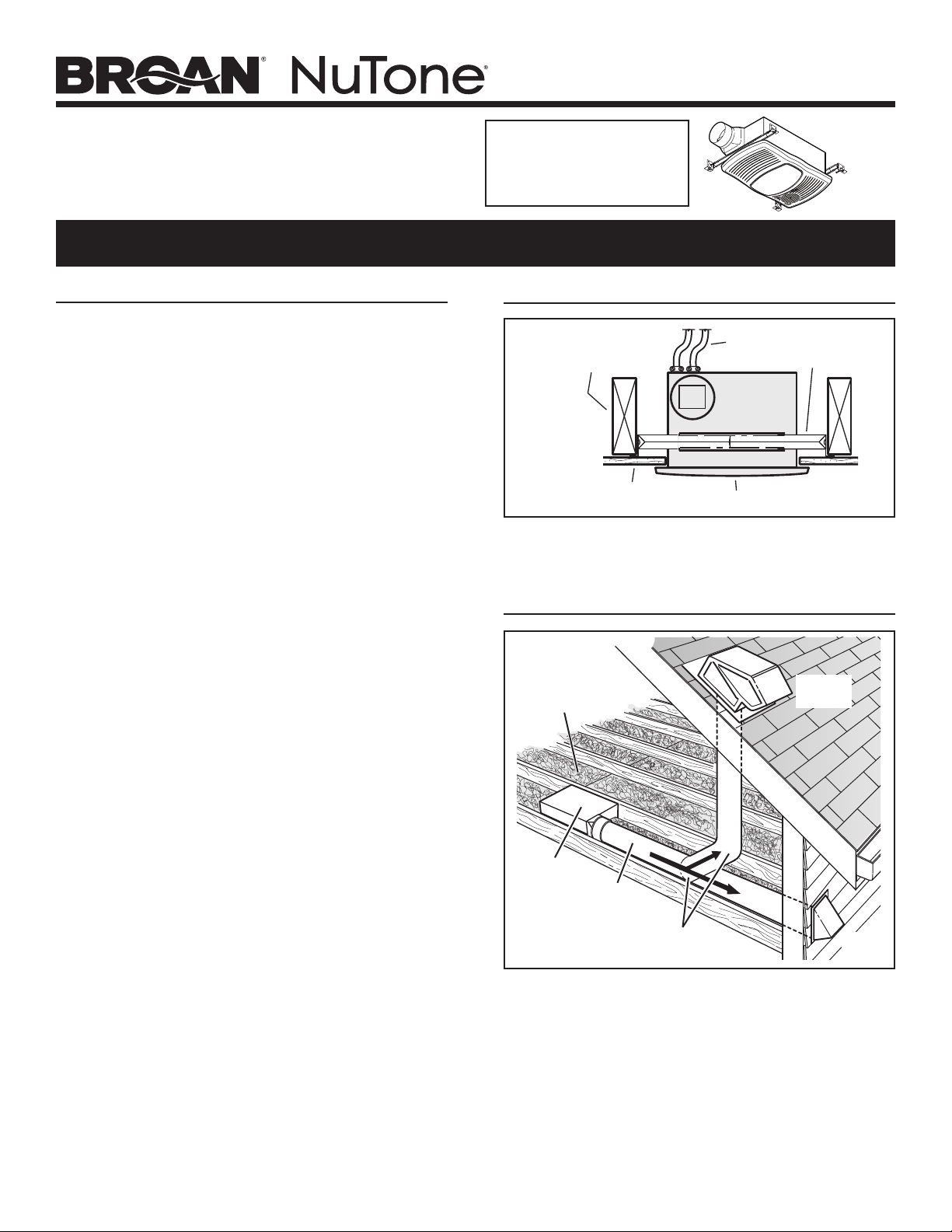
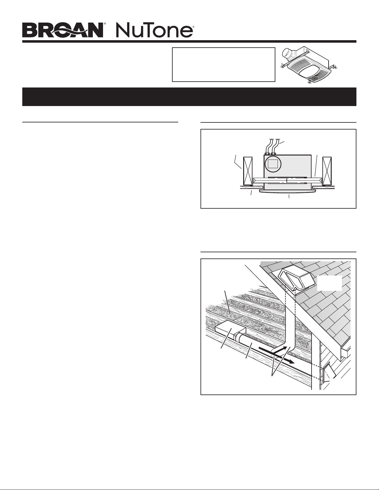
PLAN THE INSTALLATION
The unit will operate most quietly and efficiently when located
where the shortest possible duct run and minimum number of
elbows will be needed.
Use a roof cap or wall cap that has a built-in damper to reduce
backdrafts.
Plan to supply the unit with proper line voltage and appropriate
power cable.
ROOF
CAP
*
4-IN. ROUND
ELBOW(S) *
4-IN.
ROUND
DUCT *
WALL
CAP
*
*
Purchase
separately
INSULATION
(Can be placed
around and over
housing.)
HOUSING
TYPICAL INSTALLATION
HOUSING
CEILING
JOIST, TRUSS,
OR I-JOISTS
MOUNTING
CHANNELS
GRILLE
CEILING
MATERIAL
POWER
CABLES
Housing mounted to joists, trusses, or I-joists.
Up to 24-inches on-center.
For Warranty Statement, Service
Parts, Technical Support, or to
Register your product, please
visit our website or call:
NuTone.com 888-336-6151.
Page 2
MODELS 765H110LB • 765H110L
INSTALLATION
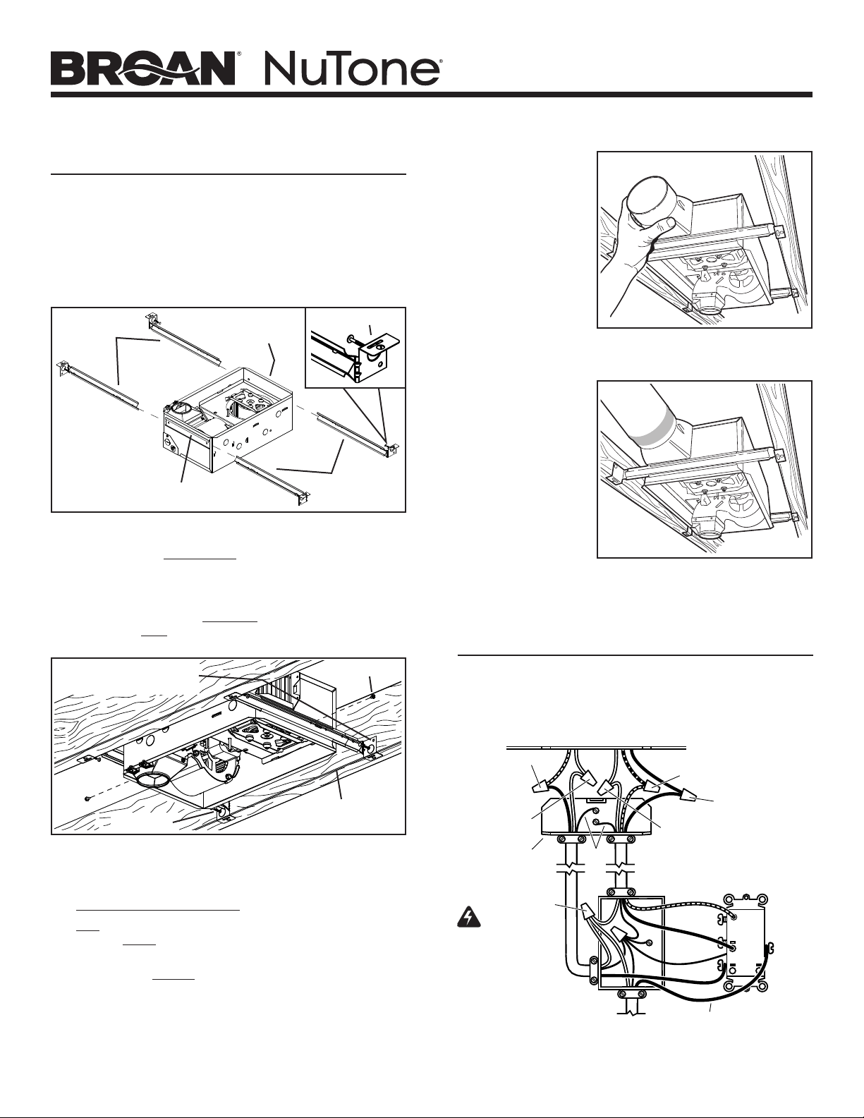
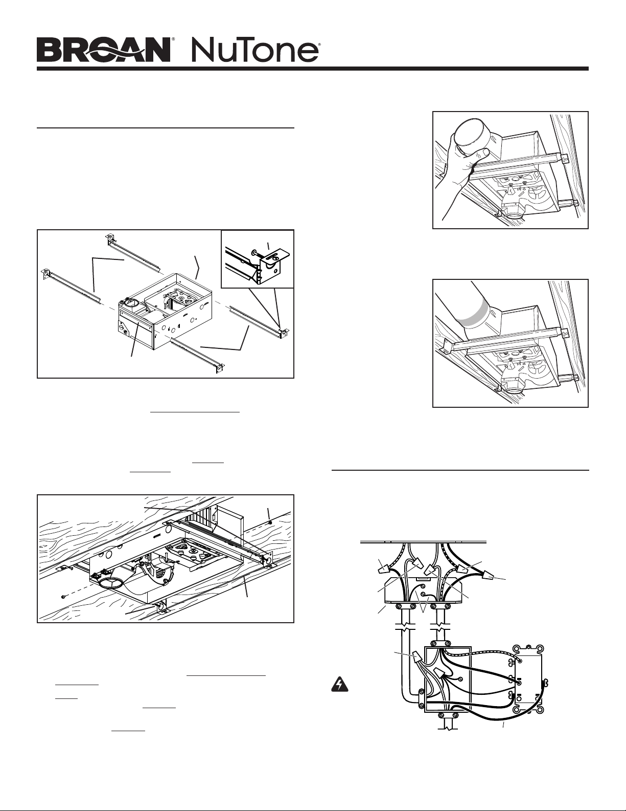
2. Mount housing.
Extend hanger bars to the width of the framing. Hold fan
in place with the hanger bar tabs wrapping around the
bottom edge of the framing.
Nail fan to framing or fasten with screws (not provided)
through holes near nails.
* To ensure a noise-free mount: Secure hanger bars
together with screws or use a pliers to crimp mounting
channels tightly around hanger bars.
1. Insert hanger bars.
Four (4) sliding hanger bars are provided to allow for
accurate positioning of housing anywhere between
framing. They can be used on all types of framing (I-joist,
standard joist, and truss construction) and span up to 24”.
Slide hanger bars into channels on housing. Make sure
hanger bar tabs face “up” as shown.
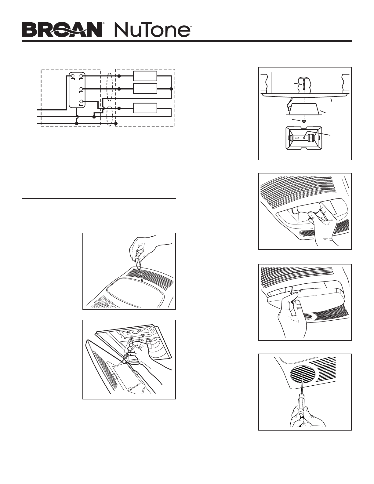
3. Attach
damper
/ duct
connector to
housing.
Snap damper /
duct connector
onto housing.
Make sure
connector is flush
with top of housing
and damper flap
falls closed.
TAB
CHANNEL
HANGER
BARS
HANGER
BARS
CHANNEL
BOTTOM EDGE
OF FRAMING
* SCREW (2)
HOLE FOR OPTIONAL
SCREW MOUNTING (4)
NAIL (4)
WARNING: To reduce the risk of fire, do not store or use
gasoline or other flammable vapors and liquids in the vicinity
of the heater.
CAUTION: High temperature, risk of fire, keep electrical cords,
drapery, furnishings, and other combustibles at least 3 feet
(0.9 m) from the front of the heater and away from the side
and rear.
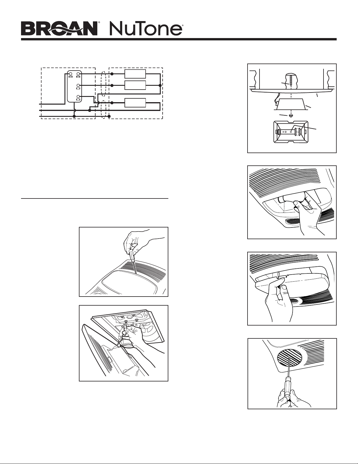
CONNECT WIRING
GREEN
WHITE
to
WHITE
HEAT
LIGHT
GROUND
120 VAC LINE IN
BLACK
BLACK
FAN
RED
WIRING PLATE
FROM VENTILATOR
VENTILATOR
HOUSING
LIGHT
&
FANHEAT
BLACK to BLACK
(Fan)
WHITE to WHITE
RED to BLUE
(Light)
BLACK to RED
(Heat)
WHITE to WHITE
BLACK
CAUTION
RATING
SPECIFICATIONS
Each two-position
rocker switch is rated 15
A @ 120VAC. The total
load on this control must
not exceed 20 A @ 120VAC.
4. Install
4-inch round
ductwork.
Connect 4-inch
round ductwork
to damper / duct
connector. Run
ductwork to a roof
cap or wall cap.
Tape all ductwork
connections to
make them secure
and air tight.
Installation work and electrical wiring must be done by a quali-
fied person(s) in accordance with all applicable codes and stan-
dards, including fire-rated construction codes and standards.
Page 3
MODELS 765H110LB • 765H110L
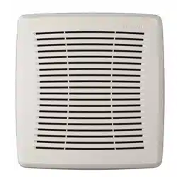
NOTE: Your
grille may
look different
than the one
shown.
8. Plug-in
light.
Hold grille
assembly up near
housing. Connect
light plug from
grille assembly to
receptacle inside
of housing.
9. Attach
grille.
Place grille/
reflector
combination
over protruding
screw and
fasten in place
using acorn nut
provided. HAND
TIGHTEN acorn
nut 1/4 turn after
it is snug.
10. Install
bulb.
The unit
accepts a
100-Watt
(maximum) E26
base bulb. (Bulb
not included.)
5. Connect electrical wiring.
Run 120 VAC house wiring to installation location. Use
proper UL approved connectors to secure house wiring to
wiring plate. Connect wires as shown in wiring diagram(s).
BLU
BLK
BLK
WHT
WHT
WHT
RED
WHT
GRD
UNIT
LIGHT
SWITCH
VENT
SWITCH
HEAT
SWITCH
LINE
IN
RED
BLK
WHT
BLK
WHT
GRD
SWITCH BOX
LIGHT
VENT
HEAT
INSTALL GRILLE & BULB
7. Remove
light lens
from grille.
Insert a small
flat-bladed
screwdriver into
the slot at one
end of the light
lens. Carefully pry
the lens out.
6. Finish ceiling.
Install ceiling material. Cut out ceiling material closely
around housing.
SCREW
GRILLE
ACORN NUT
LIGHT
REFLECTOR
BOTTOM VIEW
USE
THIS
HOLE
12. Rotate
heater
grille.
Use a flat-bladed
screwdriver to
rotate the round
heater grille to
provide heat
in the desired
direction.
11. Attach
light lens.
Hook the tabs
on one end of
the lens into the
slot in the grille.
Lift other end
of lens up and
snap into place.

Page 4
MODELS 765H110LB • 765H110L
OPERATION
Before using heater, make sure heater has been properly installed
according to installation steps beginning with the "TYPICAL IN-
STALLATION" section on page 1.
Use a 3-Function Control to operate the heater, fan, and light
separately. See “Connect Wiring” for details.

Page 5
MODELS 765H110LB • 765H110L
MAINTENANCE
The following maintenance and cleaning tasks can be performed
by the user. All other servicing must be performed by an autho-
rized technician If you have any questions, please consult with
our customer service department at: 800-558-1711.
TO REPLACE BULB
Remove lens by gently depressing sides and pull down. Use a
maximum 100-Watt E26 base bulb.
LUBRICATION
The heater is permanently lubricated and never needs oiling or
disassembly.
CLEANING
Clean heater once a month as follows:
1. Turn off power at service panel.
2. Make sure heating element is cool.
3. Use a soft brush attachment to gently vacuum grille openings
or wipe grille clean with a soft cloth.
4. Restore power.
CAUTION: METAL AND ELECTRICAL PARTS SHOULD NEVER
BE IMMERSED IN WATER.

Page 6
MODELS 765H110LB • 765H110L
1102459A
This page intentionally left blank.
Página 7
MODELOS 765H110LB • 765H110L
VENTILADOR CON
CALEFACTOR Y LUZ
LEA Y CONSERVE ESTAS INSTRUCCIONES
PLANIFICACIÓN
El ventilador funcionará con más eficiencia y menos ruido si se
ubica en un sitio donde requiera el tramo de conductos más corto
posible y un mínimo número de codos.
Instale una tapa de techo o de pared que tenga un regulador de
tiro integrado a fin de reducir los contratiros.
Alimente la unidad con el voltaje de línea y el cable alimentador
apropiados.
TAPA DE
TECHO *
CODO(S)
REDONDO(S)
DE 4 PULG. *
CONDUCTO
REDONDO DE
4 PULG. *
TAPA DE
PARED *
* Se compra por
separado
AISLAMIENTO
(puede ponerse
alrededor de, y sobre
la cubierta)
CUBIERTA
INSTALACIÓN TÍPICA
CUBIERTA
VIGA DE TECHO,
TIRANTE O VIGA EN I
RANURAS DE
MONTAJE
REJILLA
MATERIAL
DEL TECHO
CABLES
ALIMENTADORES
La cubierta se monta en las vigas, tirantes o vigas en I.
Hasta 24 pulg. (61 cm) de centro a centro.
Si desea consultar la declaración de
garantía, repuestos de servicio, apoyo
técnico o para registrar su producto, visite
nuestro sitio web o llame:
NuTone.com 888-336-6151.
INSTRUCCIONES IMPORTANTES
LEA TODAS LAS INSTRUCCIONES ANTES DE INSTALAR
O USAR ESTE CALENTADOR.
Para reducir el riesgo de incendios, descargas eléctricas o lesiones personales, observe
las siguientes precauciones:
1. Use la unidad solo de la manera indicada por el fabricante. Si tiene preguntas,
comuníquese con el fabricante a la dirección o al número telefónico que se incluye
en la garantía.
2. Antes de dar servicio a la unidad o de limpiarla, interrumpa el suministro eléctrico
en el panel de servicio y bloquee los medios de desconexión del servicio para evitar
que la electricidad se reanude accidentalmente. Cuando no sea posible bloquear
los medios de desconexión del servicio, fije firmemente una señal de advertencia
(como una etiqueta) en un lugar visible del panel de servicio.
3. El trabajo de instalación y el cableado eléctrico deben estar a cargo de personal
capacitado, de acuerdo con todos los códigos y normas correspondientes,
incluidos los códigos y normas de construcción específicos sobre protección contra
incendios.
4. Al cortar o perforar a través de la pared o del cielo raso, tenga cuidado de no dañar
el cableado eléctrico ni otros servicios ocultos.
5. Este calentador se calienta cuando se usa. Para evitar quemaduras, no deje que
la piel desnuda toque las superficies calientes. Mantenga materiales combustibles
como muebles, almohadas, ropa de cama, papeles, ropa, etc., así como las
cortinas, por lo menos a 3 pies (0.9 m) de la parte delantera del calentador.
6. Es necesario tener extremo cuidado cuando se use un calentador cerca de niños o
personas inválidas, y siempre que el calentador se deje funcionando y sin atención.
7. No haga funcionar ningún calentador después de que presente una falla.
Desconecte la energía eléctrica en el panel de servicio y pida que un electricista
acreditado inspeccione el calentador antes de volverlo a usar.
8. No lo use en exteriores.
9. Para desconectar el calentador, mueva los controles a la posición de apagado y
desconecte la energía eléctrica al circuito del calentador en el panel de desconexión
principal (o active el interruptor de desconexión interna, si existe).
10. No inserte ni permita que objetos extraños entren en la abertura de ventilación
o de escape, pues esto puede ocasionar una descarga eléctrica, un incendio o
daños al calentador.
11. Para prevenir un posible incendio, no bloquee la entrada o salida del aire de ninguna
manera.
12. El calentador tiene piezas calientes y que pueden generar arcos eléctricos o
chispas en el interior. No lo use en áreas donde se use o almacene gasolina,
pintura o vapores o líquidos flamables.
13. Use este calentador solamente como se describe en este manual. Cualquier otro
uso no recomendado por el fabricante puede ocasionar un incendio, una descarga
eléctrica o lesiones a personas.
14. Este producto debe ser conectado a tierra.
15. No instale esta unidad sobre una bañera o ducha.
16. Este producto está diseñado para instalarse solamente en techos planos. El
confort óptimo se obtiene en instalaciones en techos de 9 pies (2.7 m) o menos.
NO MONTE ESTE PRODUCTO EN LA PARED.
17. Instálelo únicamente en techos, a distancias mínimas de 6 pulg. (15 cm) de
cualquier pared.
18. No conecte el calentador a un variador de luz o control de velocidad.
19. Proporcione un circuito por separado de 20 A. Utilice un cable eléctrico calibre
12 de un tipo conforme al código. Utilice un cable eléctrico clasificado para por lo
menos 90
O
C.
20. Para asegurar una mayor eficiencia, instale el calentador de manera que el calor
esté dirigido hacia el área de la bañera o ducha. Evite dirigir el calor hacia paredes
o ventanas.
GUARDE ESTAS INSTRUCCIONES
Página 8
MODELOS 765H110LB • 765H110L
INSTALACIÓN
2. Monte la cubierta.
Abra las barras de suspensión hasta el ancho de la estructura.
Sostenga el ventilador en su sitio envolviendo las lengüetas de
las barras de suspensión alrededor del borde inferior de la
estructura.
Clave el ventilador a la estructura o sujételo con tornillos (no
incluidos)
a través de los orificios que están cerca de los clavos.
* Para lograr un montaje silencioso: acople y fije las barras de
suspensión con tornillos, o con un alicate doble los canales de
montaje bien justos alrededor de las barras de suspensión.
1. Inserte las barras de suspensión.
Se proporcionan cuatro (4) barras de suspensión deslizantes
para facilitar la colocación adecuada de la cubierta en cualquier
parte entre la estructura. Estas barras se adaptan a toda clase de
estructuras (construcciones de vigas “I”, vigas estándar y tirantes) y
se extienden a un máximo de 24 pulg. (61 cm).
Deslice las barras de suspensión en los canales de la cubierta.
Asegúrese de que las lengüetas de las barras de suspensión estén
de cara hacia arriba, tal como se muestra.
3. Acople el
conector del
regulador
de tiro/
conducto a
la cubierta.
Conecte a presión
el
conectador del
regulador
de tiro/
conducto en la
cubierta. Asegúrese
de que el conector esté al
ras con la parte superior
de la cubierta y que
la aleta del regulador
caiga cerrada.
LENGÜETA
CANAL
BARRAS DE
SUSPENSIÓN
BARRAS DE
SUSPENSIÓN
CANAL
BORDE INFERIOR DE
LA ESTRUCTURA
*
TORNILLO (2)
ORIFICIO PARA MONTAJE
OPCIONAL CON TORNILLO (4)
CLAVO (4)
ADVERTENCIA: Para reducir el riesgo de incendio, no almacene
ni use gasolina u otros vapores y líquidos flamables en las
cercanías del calentador.
PRECAUCIÓN: Temperatura alta, el riesgo de incendio, mantenga
los cables eléctricos, cortinas, muebles y otros materiales
combustibles por lo menos 3 pies (0,9 m) del frente del calentador
y lejos de la cara y la parte trasera.
CONEXIÓN ELÉCTRICA
VERDE
BLANCO con
BLANCO
CALOR
LUZ
TIERRA
LÍNEA DE ENTRADA
DE 120 VCA
NEGRO
NEGRO
VENTILADOR
ROJO
PLACA DE CABLEADO
DEL VENTILADOR
CUBIERTA DEL
VENTILADOR
LUZ
Y
VENTILADORCALOR
NEGRO con
NEGRO (ventilador)
BLANCO con
BLANCO
ROJO con
AZUL (luz)
NEGRO con
ROJO (calor)
BLANCO con
BLANCO
NEGRO
PRECAUCIÓN
CAPACIDAD
NOMINAL
Cada interruptor
oscilante de dos
posiciones tiene una capacidad nominal de
15 A a 120 VCA. La carga total de
este control no puede ser mayor de 20 A a 120 VCA.
4. Instale el
conducto
redondo de
4 pulg.
Conecte el conducto
redondo de 4 pulg.
al conector del
regulador/conducto.
Extienda el conducto
hacia una tapa de
techo o tapa
de pared. Encinte
todas
las conexiones
de los conductos
para fijarlas y hacerlas herméticas al aire.
El trabajo de instalación y el cableado eléctrico deben estar a
cargo de personal capacitado, de acuerdo con todos los códi-
gos y normas correspondientes, incluidos los códigos y normas
de construcción especícos sobre protección contra incendios.
Página 9
MODELOS 765H110LB • 765H110L
10. Instale la
bombilla.
La unidad acepta
una bombilla
incandescente
de 100 watts
(máximo)
bombilla de base
E26. (Bombilla no
incluida).
8. Conecte
la luz.
Sostenga el conjunto
de la rejilla cerca de
la cubierta. Conecte
el enchufe de la luz
del conjunto de la
rejilla al receptáculo
dentro de la cubierta.
9. Fije la
rejilla.
Coloque el conjunto
rejilla/reflector
sobre el tornillo que
sobresale, y fíjelo
usando la tuerca
de caperuza que
se proporciona.
APRIETE CON LA
MANO la tuerca
de caperuza ¼ de
vuelta después de
que
esté ajustada.
5. Conecte los cables eléctricos.
Extienda el cableado de la casa de 120 VCA al lugar de la instalación.
Utilice conexiones aprobadas por UL para asegurar el cableado de la
casa a la placa de cableado. Conecte los cables tal como se ilustra en
los diagramas de cableado.
AZUL
NEGRO
BLANCO
TIERRA
UNIDAD
INTERRUPTOR
DE
LUZ
INTERRUPTOR
DEL VENTILADOR
INTERRUPTOR
DEL CALEFACTOR
LÍNAEA DE
ENTRADA
R OJO
NEGRO
NEGRO
BLANCO
BLANCO
BLANCO
BLANCO
R OJO
TIERRA
BLANCO
NEGRO
CAJA DE INTERRUPTOR DOBLE
LUZ
VENTILADOR
CALOR
INSTALE LA REJILLA Y
LA BOMBILLA
7. Quite la
lente de luz
de la rejilla.
Inserte un pequeño
destornillador plano
en la rejilla en un
extremo de la lente de
luz. Haga palanca con
cuidado para retirar la
lente.
6. Termine el techo.
Instale el material del techo. Corte el material del techo alrededor de la
cubierta.
TORNILLO
REJILLA
TUERCA DE
CAPERUZA
REFLECTOR
DE LUZ
VISTA INFERIOR
UTILICE
ESTE
ORIFICIO
12. Gire la
rejilla del
calefactor.
Con un
destornillador
plano, gire la rejilla
del calefactor
redonda para
proporcionar
calefacción en la
dirección deseada.
11.
Fije la lente
de luz.
Enganche las
lengüetas por
un extremo de la
lente en la ranura
de la rejilla.
Levante el otro
extremo de la
lente y fíjela en su
lugar.
NOTA: Su parrilla
puede verse
diferente a la que
se muestra.
Página 10
MODELOS 765H110LB • 765H110L
OPERACIÓN
Antes de usar el calentador, asegúrese de que esté instalado ad-
ecuadamente, de acuerdo con los pasos de instalación indicados
en “INSTALACIÓN TYPICA” en la página 7.
Utilice un control de 3 funciones para operar el calefactor, el
ventilador y la luz por separado (vea los detalles en la sección
“Conexión eléctrica”).
Página 11
MODELOS 765H110LB • 765H110L
MANTENIMIENTO
El usuario puede realizar las siguientes tareas de mantenimiento
y limpieza. Todos los demás servicios los debe realizar un técnico
autorizado. Si tiene preguntas, consulte a nuestro departamento
de servicio al cliente llamando al: 800-558- 1711.
PARA REEMPLAZAR LA LAMPARA
Quite el lente, presionando suavemente los lados y empuje. Use
una bombilla incandescente de 100 watts (máximo) bombilla de
base E26.
LUBRICACIÓN
El calentador está permanentemente lubricado y nunca necesi-
tará ponerle aceite ni desarmarlo.
LIMPIEZA
Limpie el calentador una vez al mes tal como sigue:
1. Apague la energía eléctrica en el panel de servicio.
2. Asegúrese de que el elemento de calefacción esté frío.
3. Use un aditamento de cepillo suave para aspirar suavemente
aberturas de la rejilla o limpie la rejilla con un paño suave.
4. Restaure la energía eléctrica.
CUIDADO: LAS PIEZAS METALICAS Y ELECTRICAS NUNCA
SE DEBEN SUMERGIR EN AGUA.

Página 12
MODELOS 765H110LB • 765H110L
1102459A
Esta página se dejó en blanco intencionalmente.