
i
Trademarks
Autel
®
and MaxiIM
®
, MaxiSys
®
, MaxiDAS
®
, MaxiScan
®
, MaxiTPMS
®
, MaxiRecorder
®
,
and MaxiCheck
®
are trademarks of Autel Intelligent Technology Corp., Ltd., registered in
China, the United States and other countries. All other marks are trademarks or
registered trademarks of their respective holders.
Copyright Information
No part of this manual may be reproduced, stored in a retrieval system or transmitted, in
any form or by any means, electronic, mechanical, photocopying, recording, or otherwise
without the prior written permission of Autel.
Disclaimer of Warranties and Limitation of Liabilities
All information, specifications and illustrations in this manual are based on the latest
information available at the time of printing.
Autel reserves the right to make changes at any time without notice. While information of
this manual has been carefully checked for accuracy, no guarantee is given for the
completeness and correctness of the contents, including but not limited to the product
specifications, functions, and illustrations.
Autel will not be liable for any direct, special, incidental, indirect damages or any
economic consequential damages (including the loss of profits).
IMPORTANT
Before operating or maintaining this unit, please read this manual carefully, paying extra
attention to the safety warnings and precautions.
For Services and Support
www.autel.com
For technical assistance in all other markets, please contact your local selling agent.

ii
Safety Information
For your own safety and the safety of others, and to prevent damage to the device and
vehicles upon which it is used, it is important that the safety instructions presented
throughout this manual be read and understood by all persons operating or coming into
contact with the device.
There are various procedures, techniques, tools, and parts for servicing vehicles, as well
as in the skill of the person doing the work. Because of the vast number of test
applications and variations in the products that can be tested with this equipment, we
cannot possibly anticipate or provide advice or safety messages to cover every
circumstance. It is the automotive technician’s responsibility to be knowledgeable of the
system being tested. It is crucial to use proper service methods and test procedures. It
is essential to perform tests in an appropriate and acceptable manner that does not
endanger your safety, the safety of others in the work area, the device being used, or the
vehicle being tested.
Before using the device, always refer to and follow the safety messages and applicable
test procedures provided by the manufacturer of the vehicle or equipment being tested.
Use the device only as described in this manual. Read, understand, and follow all safety
messages and instructions in this manual.
Safety Messages
Safety messages are provided to help prevent personal injury and equipment damage.
All safety messages are introduced by a signal word indicating the hazard level.
DANGER
Indicates an imminently hazardous situation which, if not avoided, will result in death or
serious injury to the operator or to bystanders.
WARNING
Indicates a potentially hazardous situation which, if not avoided, could result in death or
serious injury to the operator or to bystanders.
Safety Instructions
The safety messages herein cover situations Autel is aware of. Autel cannot know,
evaluate or advise you as to all of the possible hazards. You must be certain that any
conditions or service procedure encountered does not jeopardize your personal safety.
DANGER
When an engine is operating, keep the service area WELL VENTILATED or attach a
building exhaust removal system to the engine exhaust system. Engines produce carbon
monoxide, an odorless, poisonous gas that causes slower reaction time and can lead to
serious personal injury or loss of life.

iii
SAFETY WARNINGS
Always perform automotive testing in a safe environment.
Wear safety eye protection that meets ANSI standards.
Keep clothing, hair, hands, tools, test equipment, etc. away from all moving or hot
engine parts.
Operate the vehicle in a well-ventilated work area, for exhaust gases are poisonous.
Put the transmission in PARK (for automatic transmission) or NEUTRAL (for manual
transmission) and make sure the parking brake is engaged.
Put blocks in front of the drive wheels and never leave the vehicle unattended while
testing.
Be extra cautious when working around the ignition coil, distributor cap, ignition wires
and spark plugs. These components create hazardous voltages when the engine is
running.
Keep a fire extinguisher suitable for gasoline, chemical, and electrical fires nearby.
Do not connect or disconnect any test equipment while the ignition is on or the
engine is running.
Keep the test equipment dry, clean, free from oil, water or grease. Use a mild
detergent on a clean cloth to clean the outside of the equipment as necessary.
Do not drive the vehicle and operate the test equipment at the same time. Any
distraction may cause an accident.
Refer to the service manual for the vehicle being serviced and adhere to all
diagnostic procedures and precautions. Failure to do so may result in personal injury
or damage to the test equipment.
To avoid damaging the test equipment or generating false data, make sure the
vehicle battery is fully charged and the connection to the vehicle DLC is clean and
secure.
Do not place the test equipment on the distributor of the vehicle. Strong electro-
magnetic interference can damage the equipment.

iv
CONTENTS
1. USING THIS MANUAL ................................................................................................... 1
CONVENTIONS ................................................................................................................... 1
2. GENERAL INTRODUCTION .......................................................................................... 2
MAXIIM IM508 TABLET ...................................................................................................... 2
XP200 ............................................................................................................................. 6
3. GETTING STARTED .................................................................................................... 14
POWERING UP ................................................................................................................ 14
POWERING DOWN ............................................................................................................ 17
4. IMMO ............................................................................................................................ 18
GETTING STARTED .......................................................................................................... 18
VEHICLE IDENTIFICATION .................................................................................................. 19
NAVIGATION .................................................................................................................... 21
IMMO ............................................................................................................................ 24
5. PROGRAMMING .......................................................................................................... 31
PROGRAMMING................................................................................................................ 31
6. DIAGNOSTICS ............................................................................................................. 34
DIAGNOSIS ...................................................................................................................... 34
GENERIC OBDII OPERATIONS .......................................................................................... 44
EXITING DIAGNOSTICS...................................................................................................... 48
7. SERVICE ...................................................................................................................... 49
OIL RESET SERVICE ........................................................................................................ 49
ELECTRONIC PARKING BRAKE (EPB) SERVICE ................................................................... 51
BMS .............................................................................................................................. 55
STEERING ANGLE SENSOR (SAS) SERVICE ....................................................................... 60
DPF SERVICE ................................................................................................................. 62
TIRE PRESSURE MONITOR SYSTEM (TPMS) SERVICE ........................................................ 69
8. UPDATE ....................................................................................................................... 72
9. SETTINGS .................................................................................................................... 74
UNIT ............................................................................................................................... 74
LANGUAGE ...................................................................................................................... 75
PRINTING SETTINGS ......................................................................................................... 75

v
REPORT SETTINGS .......................................................................................................... 76
FIRMWARE UPGRADE ....................................................................................................... 76
MULTITASK ..................................................................................................................... 76
AUTO UPDATE ................................................................................................................. 77
CAR ORDER .................................................................................................................... 77
SYSTEM SETTINGS........................................................................................................... 77
ABOUT ............................................................................................................................ 78
10. REMOTE DESK ............................................................................................................ 79
11. DATA MANAGER ......................................................................................................... 81
OPERATIONS ................................................................................................................... 81
12. SHOP MANAGER ........................................................................................................ 86
VEHICLE HISTORY ............................................................................................................ 87
WORKSHOP INFORMATION ................................................................................................ 89
CUSTOMER MANAGER ...................................................................................................... 89
13. FUNCTION VIEWER .................................................................................................... 91
14. SUPPORT .................................................................................................................... 93
PRODUCT REGISTRATION ................................................................................................. 93
SUPPORT SCREEN LAYOUT............................................................................................... 94
MY ACCOUNT .................................................................................................................. 94
COMMUNITIES ................................................................................................................. 95
DATA LOGGING................................................................................................................ 96
TRAINING ........................................................................................................................ 96
FAQ .............................................................................................................................. 96
15. ACADEMY .................................................................................................................... 97
16. QUICK LINK ................................................................................................................. 98
17. MAINTENANCE AND SERVICE .................................................................................. 99
MAINTENANCE INSTRUCTIONS ........................................................................................... 99
TROUBLESHOOTING CHECKLIST ...................................................................................... 100
ABOUT BATTERY USAGE ................................................................................................ 101
18. COMPLIANCE INFORMATION .................................................................................. 102
FCC COMPLIANCE ......................................................................................................... 102
SAR ............................................................................................................................ 103
RF WARNING STATEMENT ...................................................................................... 103

vi
ROHS COMPLIANCE .................................................................................................. 103
CE COMPLIANCE ...................................................................................................... 103
19. WARRANTY ............................................................................................................... 104

1
1. Using this Manual
This manual contains device usage instructions.
Some illustrations shown in this manual may contain modules and optional equipment
that are not included in your system.
Conventions
The following conventions are used.
Bold Text
Bold text is used to highlight selectable items such as buttons and menu options.
Example:
Tap OK.
Notes and Important Messages
Notes
A NOTE provides helpful information such as additional explanations, tips, and
comments.
Important
IMPORTANT indicates a situation which, if not avoided, may result in damage to the
tablet or vehicle.
Hyperlink
Hyperlinks are available in electronic documents. Blue italic text indicates a selectable
hyperlink and blue underlined text indicates a website link or an email address link.
Illustrations
Illustrations used in this manual are samples, the actual testing screen may vary for each
vehicle being tested. Observe the menu titles and on-screen instructions to make correct
option selection.
2
2. General Introduction
When it comes to ultra-portability, MaxiIM IM508 is your perfect companion. Installed with
a fast quad-core processor, IM508 offers maximum convenience and swift diagnosis.
The intuitive user screen makes using the device effortless through a 7-inch LCD
touchscreen that displays at 1024 x 600 quality. Together with the ability to quickly read
and clear DTCs for all available modules of the majority of the makes and models on the
market, IM508 provides you with superior special functions, including Oil Reset, EPB
(Electronic Parking Brake), SAS (Steering Angle Sensor), BMS (Battery Management
System), DPF (Diesel Particulate Filter), IMMO, and TPMS (Tire Pressure Monitoring
System). What is more, together with the key programmer XP200, IM508 is capable of
providing extraordinary service functions for the immobilizer system.
This manual describes the construction and operation of the device and how it works to
deliver diagnostic solutions.
MaxiIM IM508 Tablet
Function Description
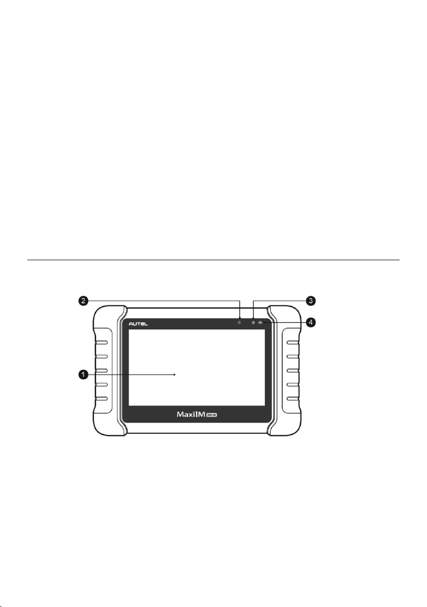
Figure 2-1 MaxiIM IM508, Front View
1. 7.0” LCD Capacitive Touchscreen
2. Ambient Light Sensor — detects ambient brightness.
3. Power LED — indicates battery level & charging or system status.
4. Vehicle Communication LED — flashes green when the Display Tablet is
communicating/linking with the vehicle’s system.
The power LED displays green, yellow or red depending on power level and operating
state.
3
A. Green
Illuminates green when the Display Tablet is charging and the battery level is
above 90%.
Illuminates green when the Display Tablet is powered on and the battery level
is above 15%.
B. Yellow
Illuminates yellow when the Display Tablet is charging and the battery level is
below 90%.
C. Red
Illuminates red when the Display Tablet is powered on and the battery level is
below 15%.
Figure 2-2 MaxiIM IM508, Back View
5. Collapsible Stand — extends from the back to allow hands-free viewing of the
Display Tablet.
6. Heat Sink
7. Built-in Battery
Figure 2-3 MaxiIM IM508, Top View
8. Mini USB OTG Port
9. Micro SD Card Slot — holds the micro SD card.
10. DB15-Pin Port — connects the main cable.
11. USB Port
12. Lock/Power Button — turns the device on & off with long press, or locks the screen

4
with short press.
Power Sources
The tablet can receive power from any of the following sources:
Internal Battery Pack
External Power Supply
Internal Battery Pack
The tablet can be powered with the internal rechargeable battery, which if fully charged
can provide sufficient power for about 4.5 hours of continuous operation.
Vehicle Power
When the tablet is connected to the test vehicle via the main cable, the tablet
automatically receives power from the vehicle.
External Power Supply
The tablet can be powered from a wall socket using the mini USB cable and USB external
power adapter. The external power supply also charges the internal battery pack.
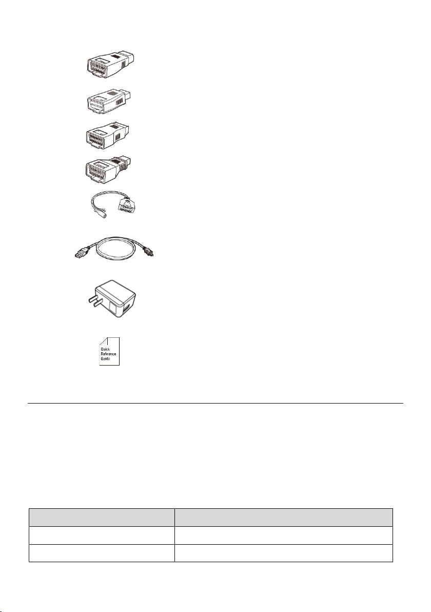
Technical Specifications
Table 2-1 Specifications
Item
Description
Recommended Use
Indoor
Operating System
AndroidTM 4.4.4
Processor
Cortex-A9 processor (1.6 GHz)
Memory
32 GB
Display
7-inch LCD capacitive touchscreen with
1024x600 resolution
Connectivity
Mini USB 2.0
USB 2.0
Wi-Fi
Micro SD card (supports up to 32 GB)
Sensors
Ambient light sensor for brightness auto
changing

5
Item
Description
Audio Output
Buzzer
Power and Battery
3.7 V/5000 mAh lithium-polymer battery
Charges via 5 V DC power supply
Tested Battery Life
Around 4.5 hours of continuous use
Battery Charging Input
5 V/1.5 A
Power Consumption
500 mA (LCD on with default brightness, Wi-
Fi on) @3.7 V
Operating Temp.
0 to 50 ° C (32 to 122 °F)
Storage Temp.
-20 to 60 °C (-4 to 140 °F)
Operating Humidity
5 to 95 % non-condensing
Dimensions (W x H x D)
237.8 mm (9.4”) x 148.6 mm (5.9”) x 35.5 mm
(1.4”)
Net Weight
788 g (2.42 lbs.)
Supported Automotive Protocols
ISO9141-2, ISO14230-2,ISO15765, K/L-Line,
Flashing Code, SAE-J1850 VPW, SAE-J1850
PWM, ISO11898(Highspeed, Middlespeed,
Lowspeed and Singlewire CAN,fault-tolerant
CAN), SAE J2610,GM UART,UART Echo
Byte Protocol, Honda Diag-H Protocol, TP2.0,
TP1.6
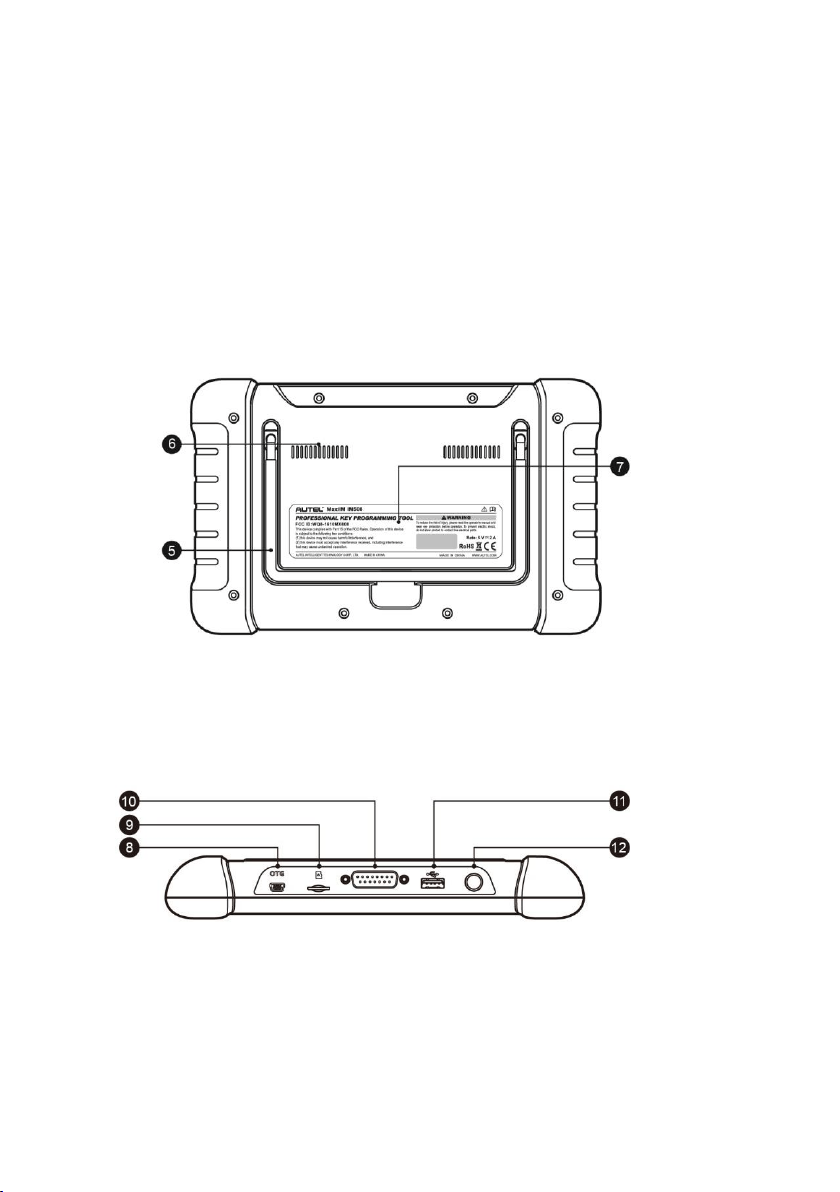
Accessory Kit
Main Cable
The Main Cable connects the tablet to the vehicle’s data link connector (DLC).
Figure 2-4 Main Cable
6
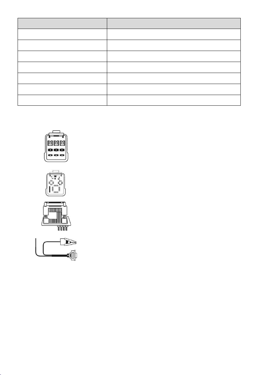
Other Accessories
Suitable for Mazda-17 Adaptor
Suitable for KIA-10 Adaptor
Suitable for KIA-20 Adaptor
Suitable for Honda-3 Adaptor
AAC001 — MED17 Cable
Mini USB Cable
Connects the tablet to the PC or DC
external power adapter.
USB External Power Adapter
Together with the mini USB cable, connects
the tablet to the external DC power port for
power supply.
Quick Guide
Device connection and diagnostic software
update instructions.
XP200
The XP200 is specially designed to read Volkswagen vehicle key chip data, clone and
generate exclusive keys, read/write on-board EEPROM data, and read/write Freescale
9S12 MCUs. By working with diagnostic tool and PC that are both loaded with
programmer software, the XP200 can read/write key chip data quickly and accurately.
Specifications
Table 2-2 Specifications
Item
Description
Operating Temperature
-10 to 50 ° C (14 to 122℉)
Storage Temperature
-20 to 60 ° C (-4 to 140℉)
7
Item
Description
Port
Mini USB, VGA_DB15
Input Voltage
5 V DC
Operating Current
< 250 mA
Maximum Consumption
1 W
Device Dimensions (L*W*H)
130 mm x 68 mm x 28 mm
Package Dimensions (L*W*H)
201 mm x 167 mm x 75 mm
Net Weight
466 g
Accessories Included
APB001 — EEPROM Adaptor
APB002 — 68HC908 Adaptor
APA002 — EEPROM Socket
APA001 — EEPROM Clamp Integrated MC9S12 Cable
8
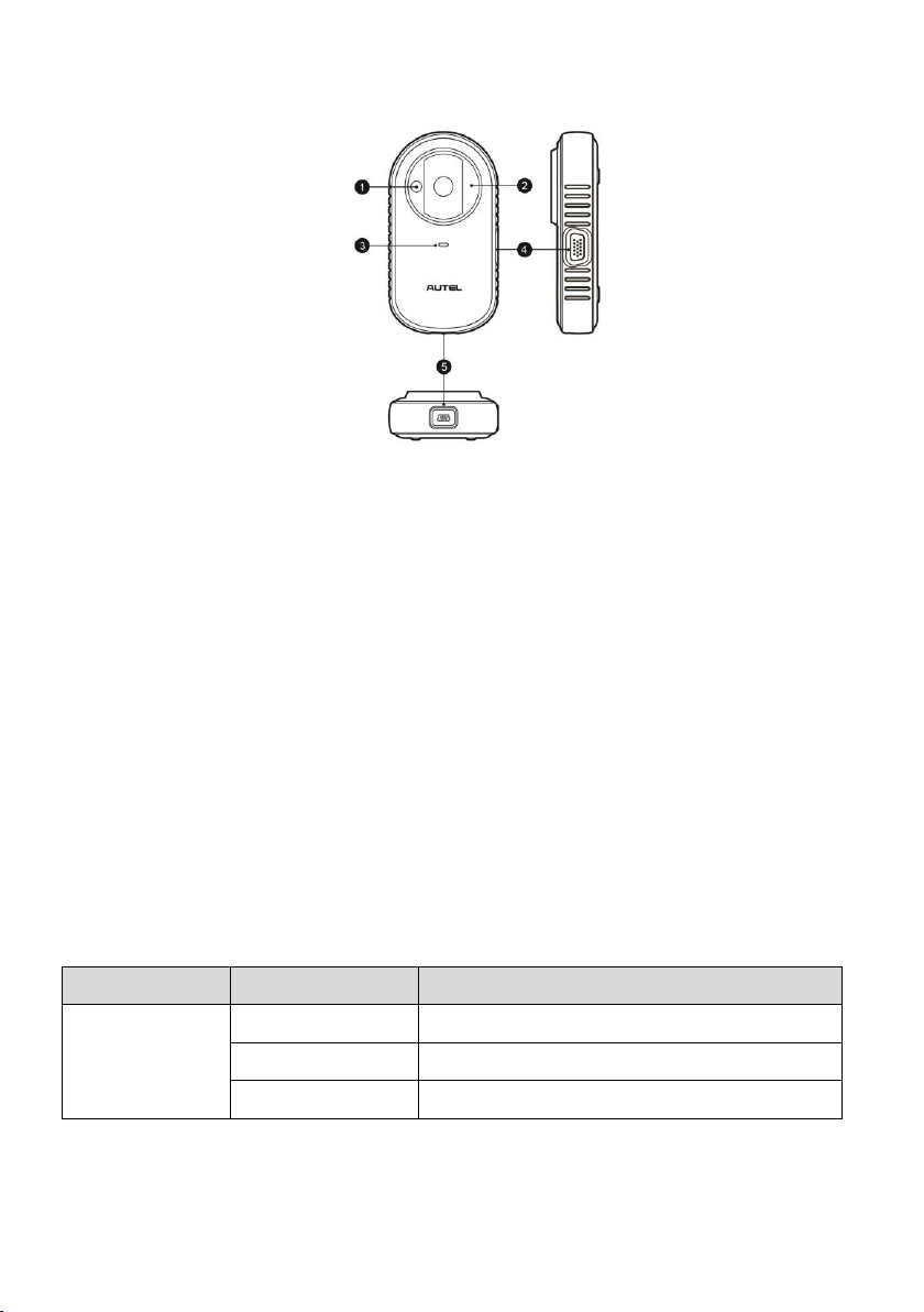
Components and Ports
Figure 2-4 XP200 Views
1. Vehicle Key Chip Slot — holds the vehicle key chip.
2. Vehicle Key Slot — holds the vehicle key.
3. Status LED Light — indicates the current operating status.
4. Connection Port — connects EEPROM Adaptor and EEPROM Clamp Integrated
MC9S12 Cable.
5. USB Port — provides data communication and power supply.
Vehicle Key Slot
Holds the Vehicle Key to read and write vehicle key information.
Vehicle Key Chip Slot
Holds the Vehicle Key Chip to read and write vehicle key chip information.
Status LED Light
The status LED of the XP200 indicates the operating status of the device.
Table 2-3 Status LED Light on the Front Panel
LED Light
Color/Status
Description
Power
Solid Green
Powered on and Default Status
Flashing Green
Communication Status
Solid Red
Error Status
9
Connection Port
There are two accessories that can be paired with the connection port: EEPROM Clamp
Integrated MC9S12 Cable and EEPROM Adaptor.
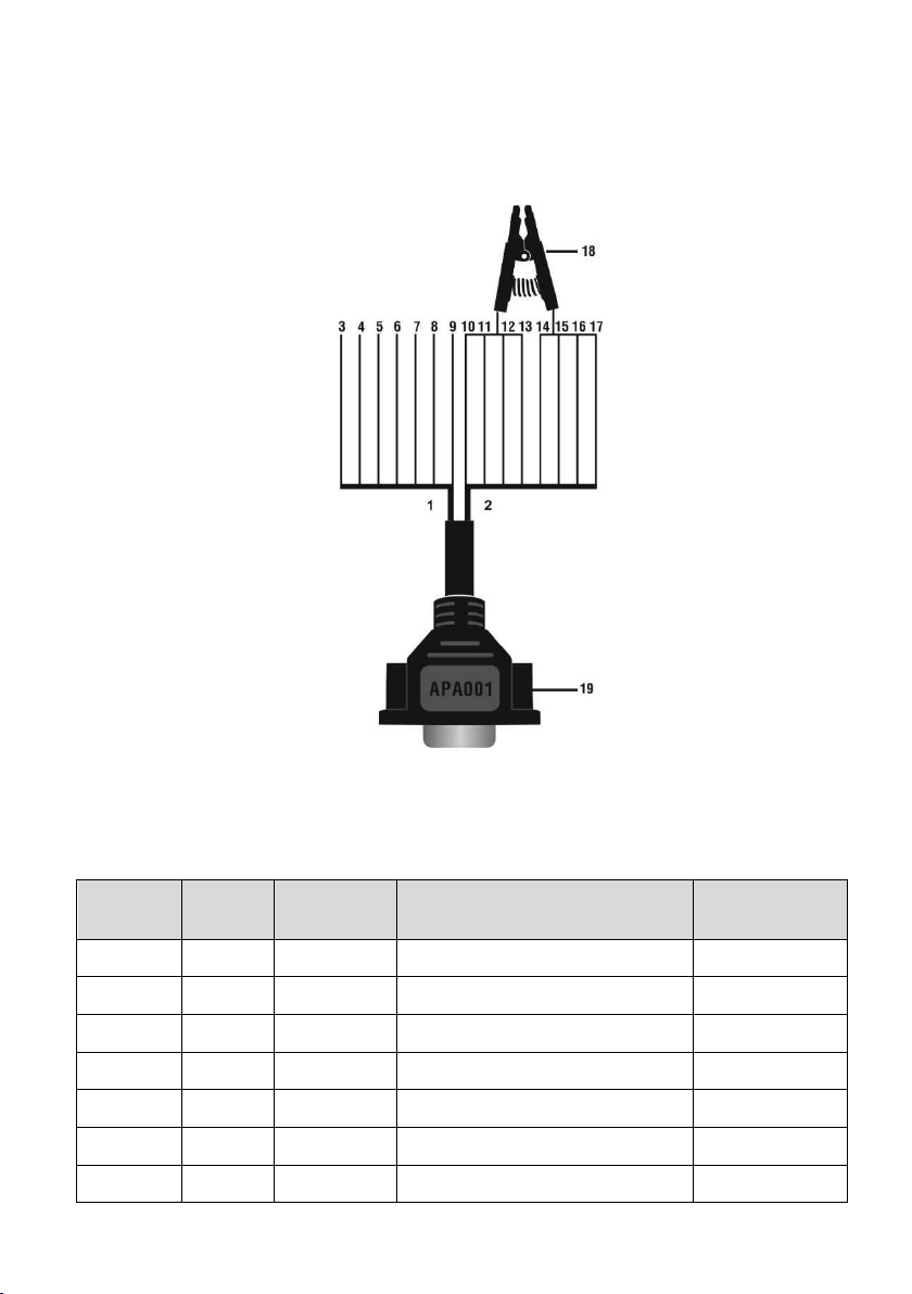
EEPROM Clamp Integrated MC9S12 Cable
Figure 2-5 EEPROM Clamp Integrated MC9S12 Cable
1. MC9S12 Cable
Table 2-4 Definitions of MC9S12 Cable
No.
Color
Definition
Pin correspond to DB15
Note
3
Green
TXCLKS
1
4
Black
GND
2
Shielded line
5
White
TOSC
6
Shielded line
6
Blue
TSW
7
7
Brown
GND
8
8
Yellow
TRESET
11
9
Red
VDD
12

10
2. EEPROM Clamp Cable
Table 2-5 Definitions of EEPROM Clamp Cable
No.
Color
Definition
Pin correspond to
DB15
Note
10
Orange
P1
5
Pin 1 is red
11
Light Grey
P2
15
12
Purple
P3
10
13
Grey
P4
4
14
Light Blue
P5
14
15
Pink
P6
9
16
Light Green
P7
3
17
Light Purple
P8
13
Pin 8 is black
Here are the possible causes for EEPROM read/write failure and data error when
connecting the clamp to the test board for EEPROM read/write:
A. EEPROM read/write operations are affected by the circuit of the connected test
board;
B. EEPROM read/write operations of the test board are affected by the read/write
operations of the clamp;
C. The signal is damaged by large resistance. A large resistance will be generated
when connecting the clamp to a fast communicating EEPROM or using a long cable
for connection.
Therefore, it is recommended to dismantle the chip on the EEPROM, weld the EEPROM
to the EEPROM adaptor or place in the EEPROM socket, and then insert it in the
EEPROM adaptor.
18. EEPROM Clamp
19. DB15 VGA Port
EEPROM Adaptor
The EEPROM adaptor is compatible with three 8-pin packaging TSSOP, SOP, DIP
connections, and each packaging reserves three same ports, so the device will function
properly when one port is damaged. For SOP8 packaging, the EEPROM adaptor can
also work with the EEPROM socket. To do this, place the pins of the SOP8 EEPROM
into the EEPROM accordingly and then insert them into the EEPROM adaptor.

11
USB Port
The USB port is used for the data communication between the XP200 and the diagnostic
device or the PC, and it is also the port for power supply charge.
EEPROM Read/Write Supported Types
Chip Type
Name
Chip Type
Name
ATMEL
AT24C01
ST
M24C04
ATMEL
AT24C02
ST
M24C08
ATMEL
AT24C04
ST
M24C16
ATMEL
AT24C08
ST
M24C32
ATMEL
AT24C16
ST
M24C64
ATMEL
AT24C32
FAIRCHILD
NM24C16U
ATMEL
AT24C64
FAIRCHILD
NM24C16UT
ATMEL
AT24C128
FAIRCHILD
NM24C17U
ATMEL
AT24C256
FAIRCHILD
NM24C17UT
ATMEL
AT24C512
MICROCHIP
85C72
ATMEL
AT24C1024
MICROCHIP
85C82
ATMEL
AT24C128_1.8
MICROCHIP
85C92
ATMEL
AT24C256_1.8
NXP
PCF8582C
ATMEL
AT24C512_1.8
NXP
PCF8594C
ATMEL
AT24C01A
NXP
PCF8598C
ST
ST24x01/ST25x01
ATMEL
AT25010
ST
ST24x02/ST25x02
ATMEL
AT25020
ST
ST24x04/ST25x04
ATMEL
AT25040
ST
ST24x08/ST25x08
ATMEL
AT25080
ST
ST24x16/ST25x16
ATMEL
AT25160
ST
M24C01
ATMEL
AT25320
ST
M24C02
ATMEL
AT25640
ATMEL
AT25128
MICROCHIP
25xx080
ATMEL
AT25256
MICROCHIP
25xx160
ATMEL
AT25512
MICROCHIP
25xx320

12
Chip Type
Name
Chip Type
Name
ATMEL
AT25010_1.8
MICROCHIP
25xx640
ATMEL
AT25020_1.8
MICROCHIP
25xx040_TSSOP
ATMEL
AT25040_1.8
MICROCHIP
25xx320_TSSOP
ATMEL
AT25080_1.8
MICROCHIP
25xx640_TSSOP
ATMEL
AT25160_1.8
CATALYST
CAT25C01
ATMEL
AT25320_1.8
CATALYST
CAT25C02
ATMEL
AT25640_1.8
CATALYST
CAT25C04
ATMEL
AT25128_1.8
CATALYST
CAT25C08
ATMEL
AT25256_1.8
CATALYST
CAT25C16
ST
M95010
CATALYST
CAT25C32
ST
M95020
CATALYST
CAT25C64
ST
M95040
CATALYST
CAT25C128
ST
M95080
CATALYST
CAT25C256
ST
M95160
ST
M35080
ST
M95320
XICOR
X5043
ST
M95640
XICOR
X5045
ST
M95128
XICOR
X25043
ST
M95256
XICOR
X25045
ST
M95512
MICROCHIP
93C06
MICROCHIP
25xx040
NATIONAL
NM93C13
NATIONAL
NM93C14
NATIONAL
NM93CS06
NATIONAL
NM93C14TM8
NATIONAL
NM93CS46
MICROCHIP
93C46X
NATIONAL
NM93CS56
MICROCHIP
93C46A
NATIONAL
NM93CS66
MICROCHIP
93C46
FAIRCHILD
FM93CS46T
MICROCHIP
93C46AX
ST
M93C46
MICROCHIP
93C46BX_93C46CX
ST
M93C56
MICROCHIP
93C56A
ST
M93C66
MICROCHIP
93C56
ST
M93C76

13
Chip Type
Name
Chip Type
Name
MICROCHIP
93C66A
ST
M93C86
MICROCHIP
93C66
ST
M93S46
MICROCHIP
93C76A
ST
M93S56
MICROCHIP
93C76
ST
M93S66
MICROCHIP
93C86A
ATMEL
AT59C11
MICROCHIP
93C86
ATMEL
AT59C22
ATMEL
AT93C46A
ATMEL
AT59C13
ATMEL
AT93C46
OKI
MSM16911
ATMEL
AT93C46R
TMC
TMC93LC46
ATMEL
AT93C56
TMC
TMC93LC56
ATMEL
AT93C57
TMC
TMC93LC57
ATMEL
AT93C66
TMC
TMC93LC66
ATMEL
AT93C76
TMC
TMC93LC86
ATMEL
AT93C86
SONY
CXK1011
SONY
CXK1012
Seiko
S_24S45
SONY
CXK1013
TOSHIBA
TC89101
Seiko
S_24H30
TOSHIBA
TC89102
Seiko
S_24H30_SOP8
TOSHIBA
TC89121
Seiko
S_24H45
TOSHIBA
TC89122
Seiko
S_24H45_SOP8
Xicor
X24C44
Seiko
S_24S30
9S12 Read/Write Supported Types
Chip Type
Name
FREESCALE
MC9S12DG128
14
3. Getting Started
Ensure the tablet is sufficiently charged or is connected to the external power supply
(see
Power Sources).
NOTE
The images and illustrations depicted in this manual may differ from the actual ones.
Powering Up
Long press the Lock/Power button on the top right of the tablet to power on the unit. The
power LED light will illuminate green. The system boots up, and displays the lock screen.
Slide the Lock icon to the left to enter the MaxiIM Job Menu or slide to the right to unlock.
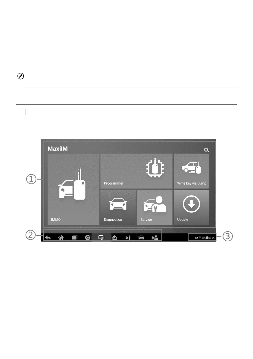
Figure 3-1 Sample Job Menu
1. Application Buttons
2. Locator and Navigation Buttons
3. Status Icons
15
NOTE
The tablet screen is locked by default when first powered on. It is recommended to lock
the screen to protect the information in the system and reduce the power consumption.
The touch screen navigation is menu driven enabling quick access to functions and
features by tapping on options headings and answering dialog windows. Detailed
descriptions of the menu structures are found in the application chapters.
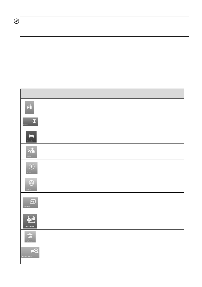
Application Buttons
Descriptions of the tool applications are displayed in the table below.
Table 3-1 Applications
Button
Name
Description
IMMO
Accesses IMMO functions menu. See IMMO.
Programming
Accesses Programming functions menu. See
Programming.
Diagnostics
Accesses diagnostic functions menu. See Diagnostics.
Service
Accesses special functions menu. See Service.
Update
Checks for the latest update available for the MaxiIM
system, and performs updates. See Update.
Settings
Accesses MaxiIM system settings menu and general
tablet menu. See Settings.
Remote Desk
Configures the unit to receive remote support using the
TeamViewer application program. See Remote Desk.
Data Manager
Accesses the organization system for saved data files.
See
Data Manager.
Shop
Manager
Accesses the Shop Manager program. See Shop
Manager
.
Function
Viewer
Provides quick search for the supported functions and
vehicles of Autel diagnostics tools. See Function
Viewer.
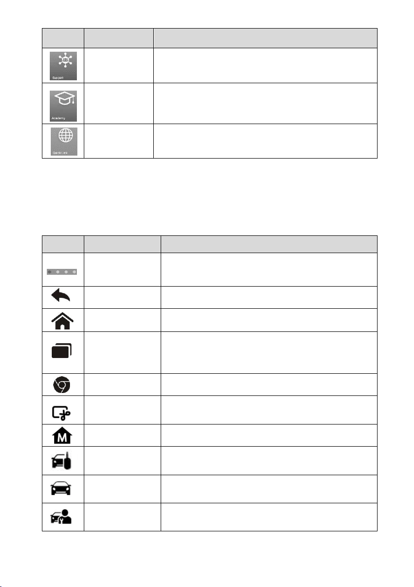
16
Button
Name
Description
Support
Launches the Support platform which synchronizes
Autel’s on-line service base station with the MaxiIM
tablet. See
Support.
Acedemy
Accesses technical tutorials and training articles about
the device usage and vehicle diagnostics techniques.
See Academy.
Quick Link
Provides associated website bookmarks to allow quick
access to product update, service, support and other
information. See
Quick Link.
Locator and Navigation Buttons
Operations of the Navigation buttons at the bottom of the screen are described in the
table below:
Table 3-2 Locator and Navigation Buttons
Button
Name
Description
Locator
Indicates the location of the screen. Swipe the screen
left or right to view the previous or next screen.
Back
Returns to the previous screen.
Android Home
Returns to Android System’s Home screen.
Recent Apps
Displays a list of applications that are currently in use.
Tap an app icon to launch. To remove an app, swipe
it to the top or bottom.
Chrome
Launches the Android built-in browser.
Screenshot
Takes a screenshot when you want to save the
displayed information.
MaxiIM Home
Returns to MaxiIM Job Menu.
IMMO Shortcut
Returns to the IMMO screen.
Diagnostic
Shortcut
Returns to the Diagnostic screen.
Service
Shortcut
Returns to the Service screen.
17
System Status Icons
As the tablet is working with the Android operating system, you may refer to Android
documents for more information.
By up sliding the bottom right corner, a Shortcuts Panel will be displayed, on which you
are allowed to set various system settings of the tablet. Operations of each button on the
panel are described in the table below:
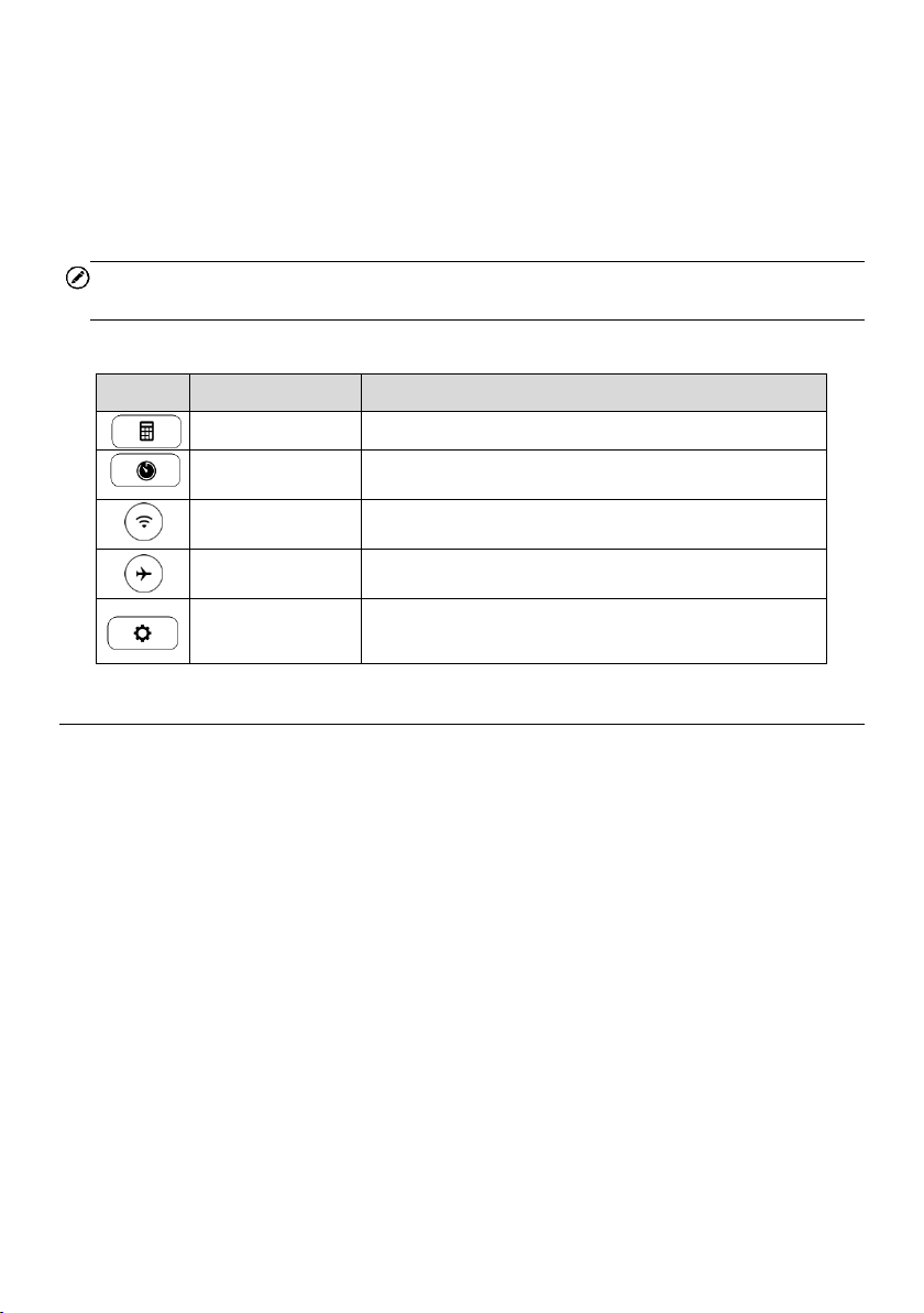
NOTE
The shortcuts buttons will be highlighted when enabled and dimmed when disabled.
Table 3-3 Shortcuts Panel Buttons
Button
Name
Description
Calculator
Launches calculator when pressed.
Clock
Launches clock when pressed.
Wi-Fi
Enables/disables Wi-Fi when pressed.
Airplane Mode
Enables/disables Airplane Mode when pressed.
System
Settings
Launches the Android System Settings screen
when pressed.
Powering Down
All vehicle communications must be terminated before shutting down the tablet. A
warning message displays if you attempt to shut down the tablet when it is
communicating with the vehicle. Forcing a shut-down while communicating may lead to
ECM problems on some vehicles. Please exit the Diagnostics application before
powering down.
To power down the tablet
1. Long press the Lock/Power Button.
2. Tap Power off option.
3. Tap OK, the tablet will turn off in a few seconds.
Reboot System
In case of system crash, long press the Lock/Power button and tap Reboot option to
reboot the system.
18
4. IMMO
The IMMO application provides Smart Mode and Expert Mode to guide technicians
performing IMMO related functions, including Key Learning, Remote Control Learning,
Remote Control Add, etc.
Getting Started
Ensure a communication link is established between the test vehicle and the tablet via
the main cable, and the XP200 is connected to the tablet with the supplied USB cable.
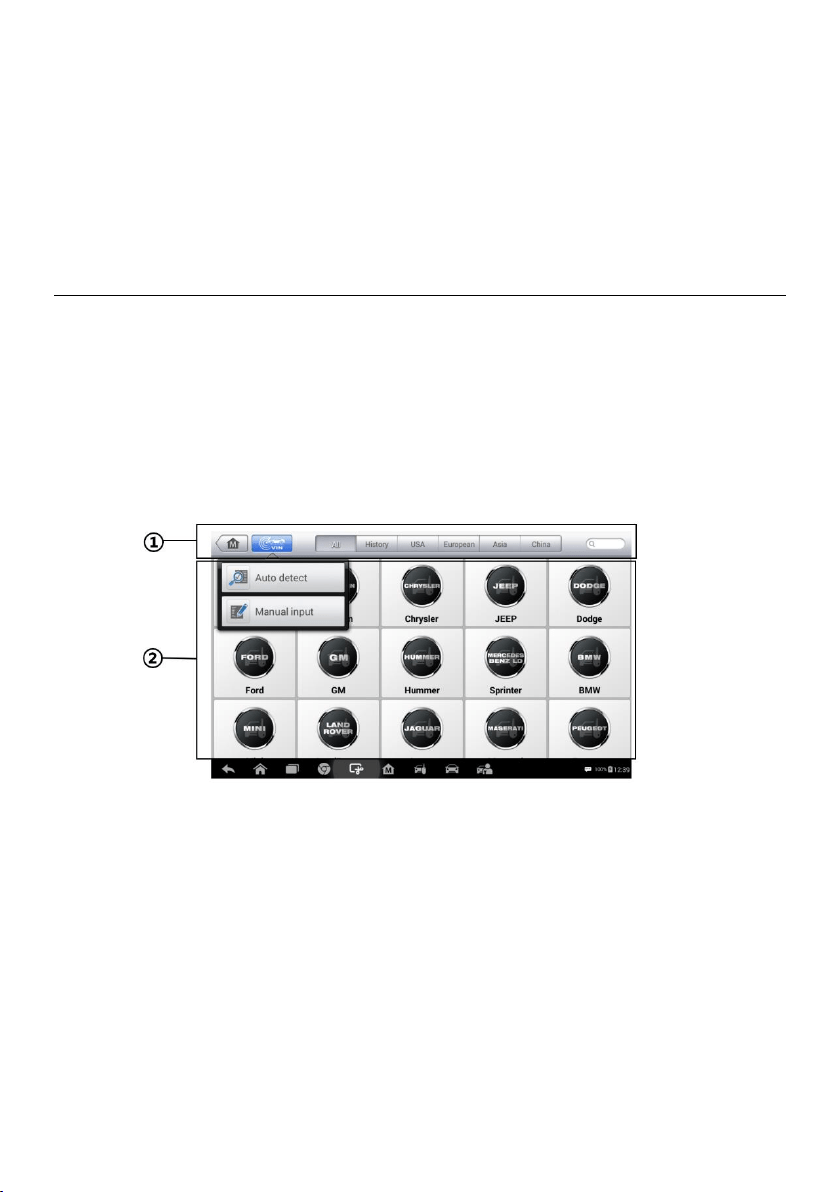
Vehicle Menu Layout
When the tablet is properly connected to the vehicle, the platform is ready to start vehicle
diagnosis. Tap on the IMMO application button on the MaxiIM IM508 Job Menu to access
the Vehicle Menu.
1. Top Toolbar Buttons
2. Manufacturer Buttons
Top Toolbar Buttons
The operations of the toolbar buttons at the top of the screen are listed and described in
the table below:
Figure 4-1 Sample Vehicle Menu
19
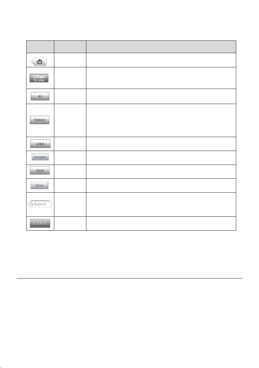
Table 4-1 Top Toolbar Buttons
Button
Name
Description
Home
Returns to the MaxiIM Job Menu.
VIN Scan
Displays a dropdown list; tap Auto Detect for auto VIN
detection; tap Manual Input to enter VIN manually.
All
Displays all the vehicle makes in the vehicle menu.
History
Displays the stored test vehicle history records. This option
provides you direct access to the previously tested vehicle
recorded during previous test sessions. See Vehicle
History
.
USA
Displays the USA vehicle menu.
European
Displays the European vehicle menu.
Asia
Displays the Asian vehicle menu.
China
Displays the Chinese vehicle menu.
Search
Displays the virtual keyboard to manually enter the specific
vehicle make required.
Cancel
Exits the search screen or cancel an operation.
Manufacturer Buttons
To begin, select the manufacturer button of the test vehicle, followed by the vehicle model
and year.
Vehicle Identification
The MaxiIM diagnostic system supports four methods for Vehicle Identification.
1. Auto VIN Scan
2. Manual VIN Input
3. Automatic Selection
4. Manual Selection

20
Auto VIN Scan and Manual VIN Input functions are applicable for IMMO, Diagnostic and
Service applications, Automatic Selection and Manual Selection are applicable for
Diagnostic and Service applications. In IMMO, except Auto VIN Scan and Manual VIN
Input methods, technicians can also manually select vehicle manufacturer, instrument
information step by step to locate the desired IMMO part, but it is a little different from
Automatic Selection and Manual Selection. Besides, as Programming does not require
connection with the vehicle, therefore, Auto VIN Scan is not applicable for this application,
and technicians can manually select the part information follow the onscreen instructions
to display the function menu.
Auto VIN Scan
The MaxiIM diagnostic system features the latest VIN-based Auto VIN Scan function to
identify vehicles and it is applied to IMMO, Programming, Diagnostic and Service
applications. IMMO provides two modes: Smart Mode and Expert Mode, and only Smart
Mode can be accessed by using Auto VIN function.
To perform Auto VIN Scan
1. Tap the IMMO application button from the MaxiIM Job Menu. The Vehicle Menu
displays.
2. Tap the VIN Scan button on the top toolbar to open a dropdown list.
3. Select Auto Detect. Once the test vehicle is successfully identified, the screen
will display the vehicle profile. Tap OK at the bottom right to confirm the vehicle
profile. If the VIN does not match with the test vehicle’s VIN, enter VIN manually
or tap Read to acquire VIN again.
4. Tap Yes to confirm the vehicle profile or No if the information is not correct.
5. The tool establishes communication with the vehicle and reads the IMMO
control unit information.
Figure 4-2 Sample Auto VIN Screen
21
Manual VIN Input
For vehicles that not supporting the Auto VIN Scan function, you may manually enter the
vehicle VIN.
To perform Manual VIN Input
1. Tap the IMMO application button from the MaxiIM Job Menu. The Vehicle Menu
displays.
2. Tap the VIN Scan button on the top toolbar.
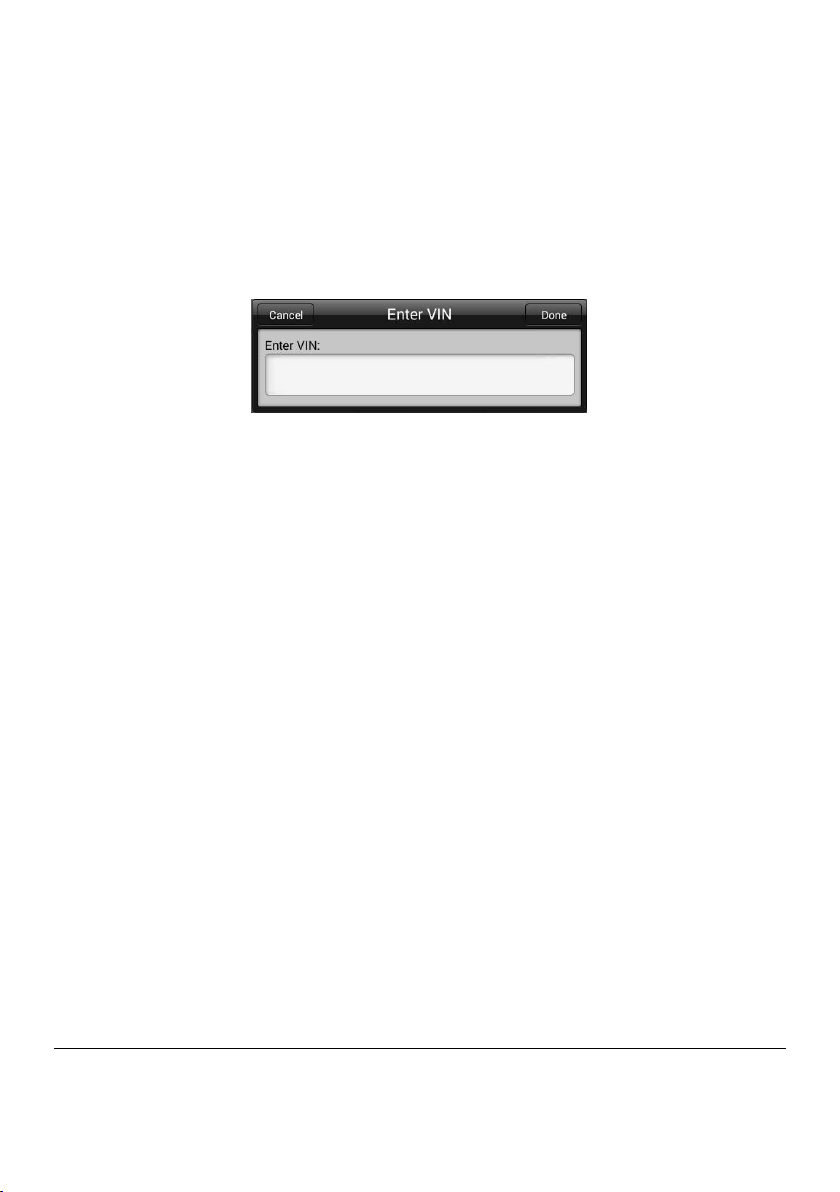
3. Select Manual Input.
Figure 4-3 Sample Enter VIN Screen
4. Tap the input box and enter the correct VIN.
5. Tap Done to complete or tap Cancel to exit Manual Input.
Automatic Selection
The Automatic Selection can be selected after selecting the test vehicle manufacturer.
To perform Automatic Selection
1. Tap the Diagnostic application button from the MaxiIM Job Menu. The Vehicle
Menu displays.
2. Tap the manufacturer button of the test vehicle.
3. Tap Automatic Selection and the VIN information will be automatically
acquired. Follow the on-screen instruction to display the function screen.
Manual Selection
When the vehicle’s VIN is not automatically retrievable through the vehicle's ECU, or the
specific VIN is unknown, the vehicle can be manually selected.
This mode of vehicle selection is menu driven, repeat the first two steps from the
automatic selection operation and tap Manual Selection. Through a series of on-screen
prompts and selections, the test vehicle is chosen. If needed, press the Back button at
the bottom right corner of the screen to return to the previous screen.
Navigation
Navigating the IMMO interface and selecting test are discussed in this section.
22
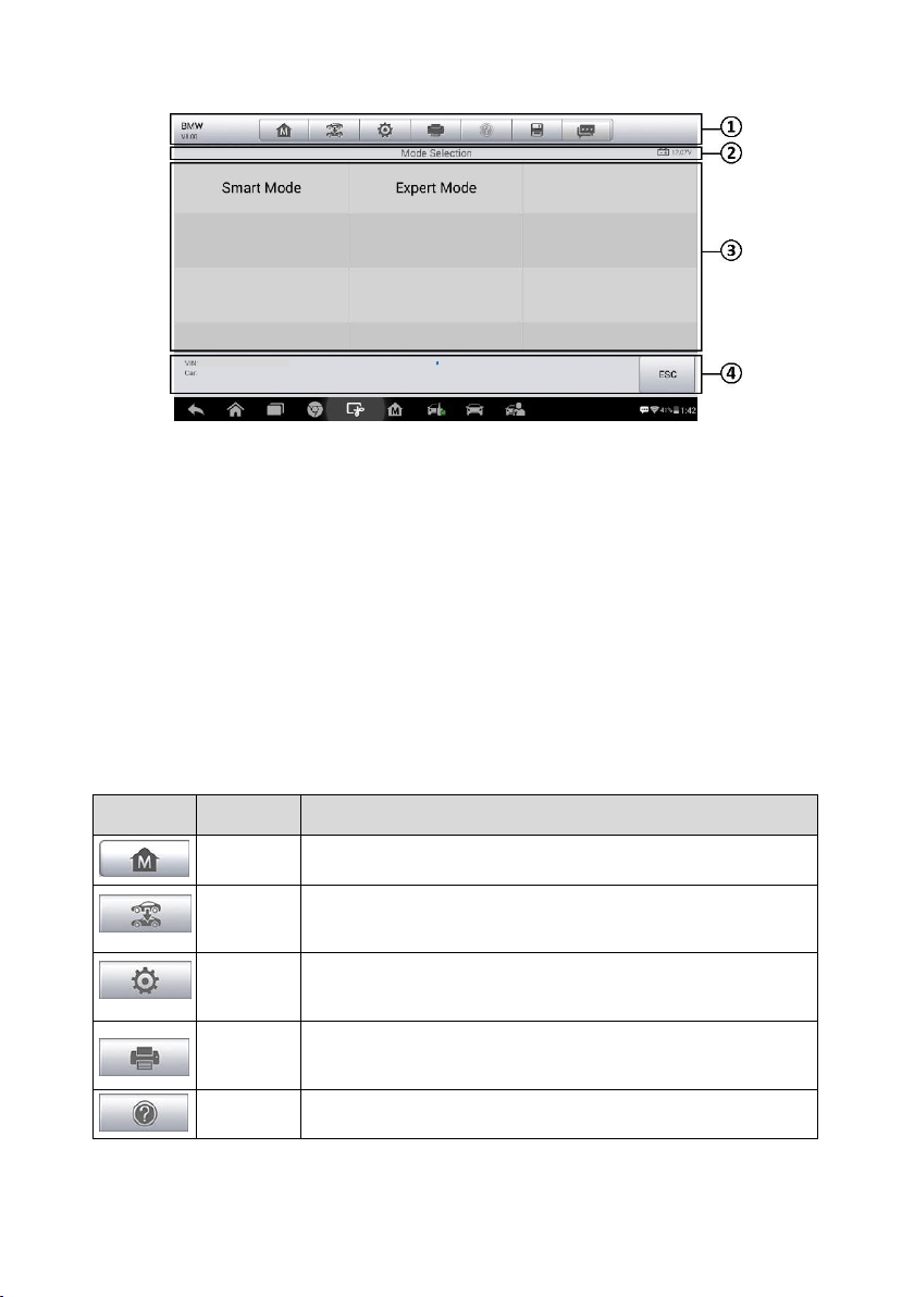
IMMO Screen Layout
The IMMO screens typically include four sections.
1. Operation Toolbar
2. Status Information Bar
3. Main Section
4. Function Buttons
Operation Toolbar
The Operation Toolbar contains a number of buttons such as print and save. The table
below provides a brief description of the operations.
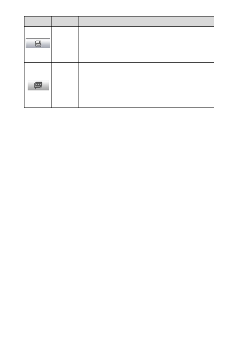
Table 4-2 Operation Toolbar Buttons
Button
Name
Description
Home
Return to the MaxiIM Job Menu.
Vehicle
Swap
Exit the function session of the currently identified test
vehicle and return to the vehicle menu screen.
Settings
Open the settings screen. See Settings.
Print
Print a copy of the displayed data. See Printing Setting for
additional information.
Help
Display operational instructions or tips.
Figure 4-4 Sample Mode Selection Screen
23
Button
Name
Description
Save
Tap to open a sub menu, tap Take a Screenshot to save
the current screen.
All saved data is stored in the Data Manager application
for later reviews. See
Data Manager.
Data
Logging
Record the communication data and ECU information of
the test vehicle. The saved data can be reported and sent
to the technical center via the Internet.
You can go to the Support application to follow up the
processing progress, see Data Logging for detailed
information.
To print data
1. Tap the IMMO application button from the MaxiIM Job Menu. The Print button
on the toolbar is available throughout the IMMO operations.
2. Tap Print. A drop-down menu displays. Tap Print This Page to print a
screenshot of the current screen.
3. A temporary file will be created and send to the connected PC for printing.
4. When the file is transferred successfully, a confirmation message displays.
To submit Data Logging reports
1. Tap the IMMO application button from the MaxiIM Job Menu. The Data Logging
button on the toolbar is available throughout the IMMO operations.
2. Tap the Data Logging button. The button displays blue during the active
recording process.
3. Tap the Data Logging button again to end recording. A submission form will
display for inputting of report information.
4. Tap the Send button to submit the report form via the Internet. A confirmation
message displays when the report has been successfully sent.
Status Information Bar
The Status Information Bar at the top of the Main Section displays the following items:
1. Menu Title — displays the menu heading of the Main Section.
2. Voltage Icon — displays the vehicle’s voltage status.
Main Section
The Main Section of the screen varies depending on the stage of operations. The Main
Section can display vehicle identification selections, the main menu, test data, messages,

24
instructions and other information. In this case, it shows the two modes IMMO provides:
Smart Mode and Expert Mode.
Function Buttons
The displayed Function Buttons vary depending on the stage of operations. Function
buttons can be used to navigate menus, to save or clear data, to exit scanning and to
perform a number of other control functions. The use of these buttons will be discussed
in detail in the following sections of the corresponding test operations.
Screen Messages
Screen messages appear when additional input is needed before proceeding. There are
three main types of on-screen messages: Confirmation, Warning, and Error.
Confirmation Messages
This type of messages usually displays as an “Information” screen to inform the user that
a selected action cannot be reversed or when an action has been initiated and
confirmation is needed to continue.
When a user-response is not required to continue, the message displays briefly.
Warning Messages
This type of messages displays a warning that a selected action may result in an
irreversible change or loss of data. An example of this type of message is the “Erase
Codes” message.
Error Messages
Error messages display when a system or procedural error has occurred. Examples of
possible errors include a disconnection or communication interruption.
Making Selections
The IMMO application is a menu driven program that presents a series of choices. As a
selection is made, the next menu in the series displays. Each selection narrows the focus
and leads to the desired test. Tap the screen to make menu selections.
IMMO
The IMMO application requires a data link to the IMMO electronic control system of the
test vehicle for diagnosis via OBDII connection. The application retrieves vehicle IMMO
information and performs IMMO related functions, including Key Learning, Remote
Control Learning, Remote Control Add, etc.
There are two options available when accessing the IMMO section:
25
1. Smart Mode — accesses to a function menu where each function is configured as a
smart guide system.
2. Expert Mode — accesses to a function menu where each function is separated from
each other.
After a mode is selected and the tablet establishes communication with the vehicle, the
corresponding function menu or selection menu displays.
Smart Mode
The Smart Mode provides guided functions with step-by-step instructions. Once the test
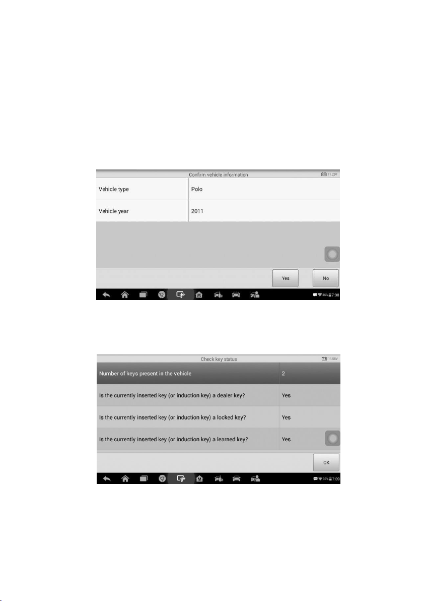
vehicle is identified, a vehicle profile will display, select Yes to continue.
Figure 4-5 Sample Vehicle Information Screen
The tablet will access the vehicle IMMO ECU to read IMMO related information. Press
OK to continue. Then the vehicle key status will display.
Figure 4-6 Sample Check Key Status Screen
Read the vehicle key status carefully and press OK to display the function menu.
26
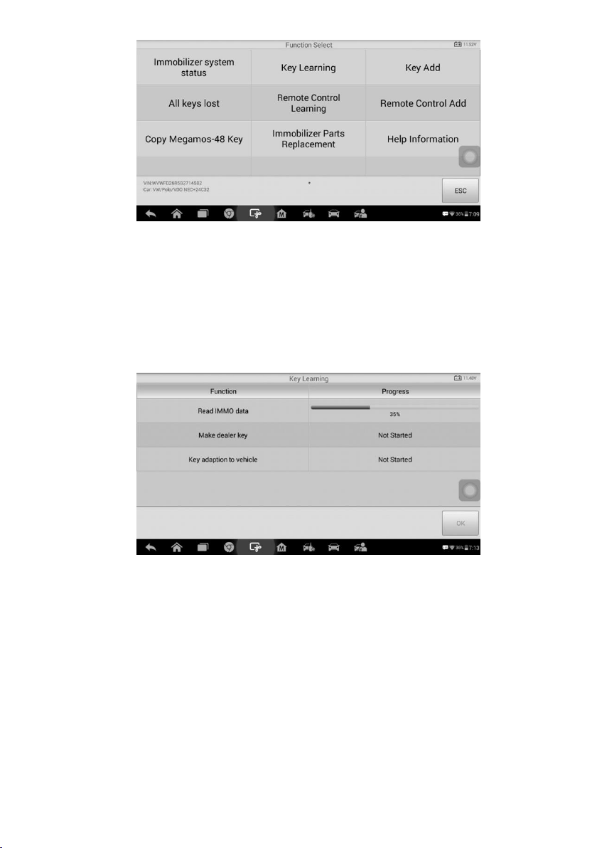
Figure 4-7 Sample Function Menu in Smart Mode
The functions vary by IMMO parts, please follow the on-screen instructions to select the
correct IMMO part.
Take Key Learning as an example.
1. Select Key Learning from the function menu. The tablet will automatically start to
read IMMO data.
Figure 4-8 Sample Key Learning Screen 1
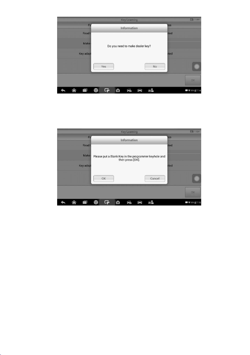
2. When Read IMMO data completes, the tablet will prompt a “Do you need to make
dealer key?” message, select Yes to confirm, or select No to quit the operation.
27
Figure 4-9 Sample Key Learning Screen 2
3. Follow the on-screen instruction to place a Blank Key in the XP200 keyhole and
press OK to continue.
Figure 4-10 Sample Key Learning Screen 3
4. If the new key is blocked, the tablet will ask if you want to unlock the key, select Yes
to continue, or select No to quit the operation.
5. A “Make dealer key success!” message displays when the process is completed
successfully.
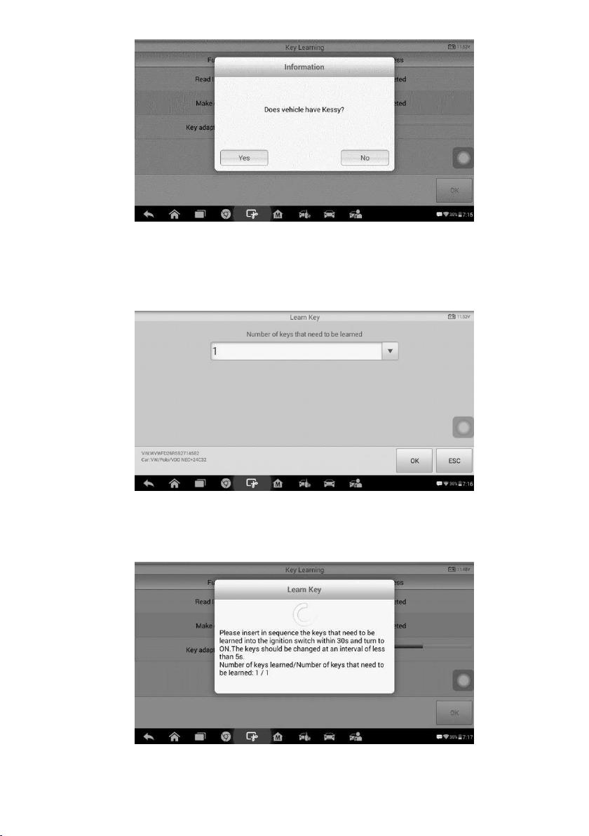
6. Then the tablet will automatically move to the next step, Key adaption to vehicle, and
the following message will prompt up.
28
Figure 4-11 Sample Key Learning Screen 4
7. Make selections according to the test vehicle.
8. Input the numbers of the keys to be learned and press OK to continue.
Figure 4-12 Sample Key Learning Screen 5
9. Follow the on-screen instructions to insert the key to be learned into the vehicle
ignition switch.
Figure 4-13 Sample Key Learning Screen 6

29
10. When Key Learning is completed successfully, the following screen displays. Press
OK to exit the function.
Figure 4-14 Sample Key Learning Screen 7
Expert Mode
Expert Mode provides skilled technicians a convenient way to perform individual IMMO
functions they need. All the function options in this mode are separated segments. If
needed, technicians can only perform one segment function instead of a whole process
provided in Smart Mode.
1. Select vehicle manufacturer in the vehicle menu, and then select the IMMO part
information step by step to locate the IMMO part and display the function menu.
Figure 4-15 Sample Expert Mode Function Menu
Take Read IMMO Data as an example.
Select Read IMMO Data from the function menu. The tablet will start to read IMMO
information. Review the data and press OK to exit.

30
Figure 4-16 Sample Read IMMO Data Screen
After read the IMMO data, technicians can perform other IMMO functions with the read
data in Expert Mode.
31
5. Programming
The Programming application requires connection between the tablet and the XP200,
and no vehicle connection is required. This application can access the key chip, read,
retrieve and write key information, as well as other key related functions.
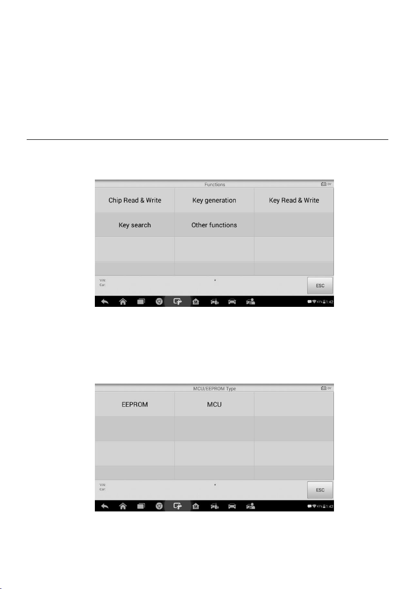
Programming
Select the vehicle manufacturer in the vehicle menu, and then follow the onscreen
instructions to select the instrument information to display the function menu.
Figure 5-1 Sample Programming Function Menu
Take Chip Read & Write as an example.
1. Select Chip Read & Write from the menu.
2. Select the chip type if needed. In this example, select EEPROM.
Figure 5-2 Sample Select Chip Type Screen
3. Select Read Operation on the next menu.

32
Figure 5-3 Sample Operations Menu
4. The chip data screen displays. Select Save to save the data, or select Cancel to
exit.
Figure 5-4 Sample Read Operation Screen
5. Type the file name and select Confirm, the chip data will be saved on the tablet. And
a “File saved successfully.” Message displays.
Figure 5-5 Sample Save Data Screen
33
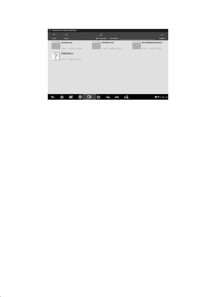
6. Select Write Operation from the operations menu. The tablet will open the default
folder, select the saved data and click Confirm to write it into a black chip.
Figure 5-6 Sample Write Operation Screen
34
6. Diagnostics
The Diagnostics application can retrieve ECU information, read & erase DTCs, and view
live data. The Diagnostics application can access the electronic control unit (ECU) for
various vehicle control systems, including engine, transmission, antilock brake system
(ABS), airbag system (SRS).
Diagnosis
The Diagnostics application enables a data link to the electronic control system of the
test vehicle for vehicle diagnosis via OBDII connection. The application performs
functional tests, retrieves vehicle diagnostic information such as trouble and event codes
and live data for various vehicle control systems, such as engine, transmission, and ABS.
There are two options available when accessing the Diagnosis section:
1. Auto Scan — starts auto scanning for all the available systems on the vehicle.
2. Control Unit — displays a selection menu of all available control units of the test
vehicle.
After a section is made and the tablet establishes communication with the vehicle, the
corresponding function menu or selection menu displays.
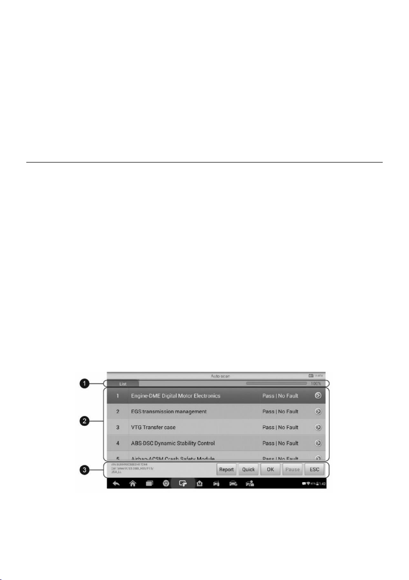
Auto Scan
The Auto Scan function performs a comprehensive scanning over all the ECUs in the
vehicle to locate systems’ faults and retrieve DTCs. An example of the Auto Scan
interface is pictured below:
Figure 6-1 Sample Auto Scan Operation Screen
1. Navigation Bar
2. Main Section
35
3. Function Buttons
Navigation Bar
List Tab — displays the scanned data in list format.
Progress Bar — indicates the test progress.
Main Section
Column 1 — displays the sequence numbers.
Column 2 — displays the scanned systems.
Column 3 — displays the diagnostic indicators describing test results.
These indicators are defined as follows:
-!-: Indicates that the scanned system may not support the code reading function,
or there is a communication error between the tablet and the control system.
-?-: Indicates that the vehicle control system has been detected, but the tablet
cannot accurately locate it.
Fault(s) | #: Fault(s) indicates there is/are detected fault code(s) present; “#”
indicates the number of the detected faults.
Pass | No Fault: Indicates the system has passed the scanning process and no fault
has been detected.
Column 4 — to perform further diagnosis or testing on a specific system item, tap the
button to the right of that item. A Function Menu screen
will display.
Function Buttons
A brief description of the operations of the Auto Scan’s Function Buttons’ are displayed
in the table below.
Table 6-1 Function Buttons in Auto Scan
Name
Description
Report
Display the diagnostic data in the report form.
Quick
Delete codes. A warning message screen will display to inform you
of possible data loss when this function is selected.
OK
Confirm the test result. Continue to the system diagnosis after the
required system is selected by tapping the item in the Main Section.
Pause
Suspend scanning and it will change to Continue button after
tapping.
ESC
Return to the previous screen or exits Auto Scan.
36
Control Unit
Manually locate a required control system for testing through a series of selection choices.
Follow the menu driven procedures and make proper selection; the application guides
the user to the proper diagnostic function menu based on selections.
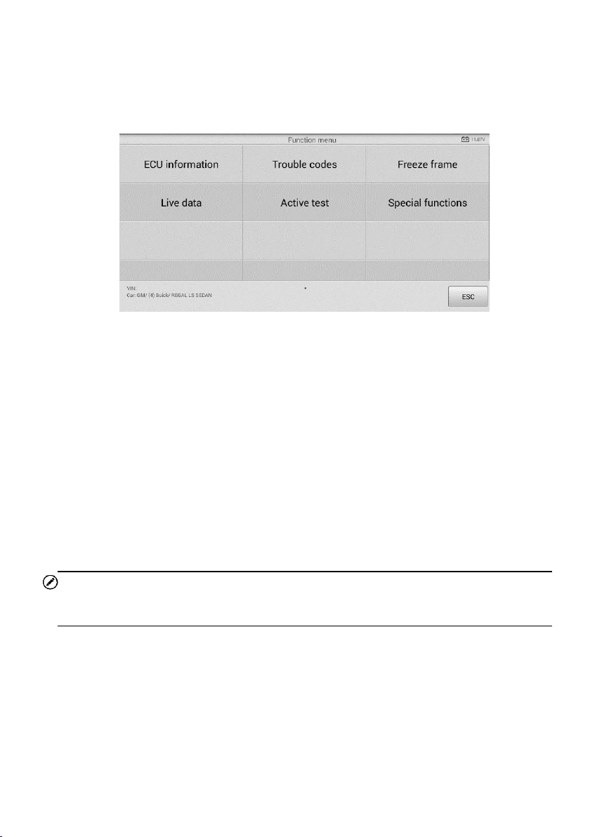
Figure 6-2 Sample Function Menu
The Function Menu options vary slightly for different vehicles. The function menu may
include:
ECU Information — provides the retrieved ECU information in detail. An information
screen opens upon selection.
Trouble Codes — includes Read codes and Erase codes functions. Displays
detailed information of DTC records retrieved from the test vehicle’s ECU and erases
DTC records and other data from the test vehicle’s ECU.
Freeze Frame — displays the freeze frame data of the DTCs.
Live Data — retrieves and displays live data and parameters from the test vehicle’s
ECU.
Active Test — accesses vehicle-specific subsystem and components test.
Special Function — performs various component adaptations.
NOTE
Toolbar functions such as saving and printing of test results can be performed throughout
diagnostic testing. Data logging and access to help information are also available.
To perform a diagnostic function
1. Establish communication with the test vehicle.
2. Identify the test vehicle by selecting from the menu options.
3. Select the Diagnosis section.
4. Locate the required system for testing by Auto Scan or through menu driven
selections in Control Unit.
5. Select the desired diagnostic function from the Function Menu.
37
ECU Information
This function retrieves and displays the specific information for the tested control unit,
including unit type, version numbers and other specifications.
The sample ECU Information screen displays as below:
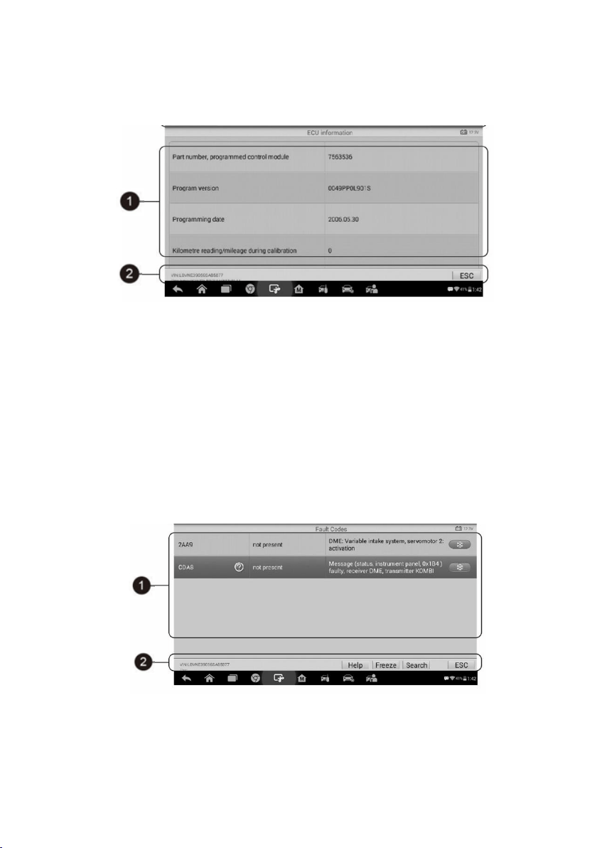
Figure 6-3 Sample ECU Information Screen
1. Main Section — the left column displays the item names; the right column displays
the specifications or descriptions.
2. Function Button — ESC (or Back) button is available; tap it to exit after viewing.
Trouble Codes
Read Codes
This function retrieves and displays the DTCs from the vehicle’s control system. The
Read Codes screen varies for each vehicle being tested. On some vehicles, freeze frame
data can also be retrieved for viewing. The sample Read Codes screen displays as below:
Figure 6-4 Sample Read Codes Screen

38
1. Main Section
Code Column — displays the retrieved codes from the vehicle.
Status Column — indicates the status of the retrieved codes.
Description Column — detailed descriptions for the retrieved codes.
Snowflake Icon — only displays when freeze frame data is available for viewing;
selecting this icon will display a data screen, which looks and behaves similar
to the Read Codes screen.
2. Function Button
Help — tap it to view fault code information, including fault description, condition
for fault identification, and driver information.
Freeze — tap it to view the freeze frame data of the selected DTC.
Search — tap it to search related fault code information on Google.
ESC — tap it to return to the previous screen or exit the function.
Erase Codes
After reading the retrieved codes and making appropriate vehicle repairs, use this
function to erase vehicle codes.
To erase codes
1. Tap Trouble Codes from the Function Menu, then tap Erase Codes.
2. A warning message displays to advice of data loss if this function is completed.
a) Tap Yes to continue. A confirming screen displays when the operation is
successfully done.
b) Tap No to exit.
3. Tap ESC on the confirming screen to exit Erase Codes.
4. Perform the Read Codes function again to check if codes have been erased
successfully.
Live Data
When this function is selected, the screen displays the data list for the selected module.
The data available for any control module varies from one vehicle to another. The
parameters display in the order that they are transmitted by the ECM, so expect variation
among vehicles.
Gesture scrolling allows for quick movement through the data list. Touch the screen and
drag your finger up or down to reposition the parameters being displayed if the data
populates more than one screen. The figure below displays a typical Live Data screen.

39
Figure 6-5 Sample Live Data Screen
1. Main Section
Name Column — displays the parameter names.
a) Check Box — tap the check box on the left side of the parameter name to
make item selection. Tap the check box again to deselect the item.
b) Drop-down Button — tap the drop-down button at the right side of the
parameter name to open a sub menu, which provides optional modes by
which to display the data.
Value Column — displays the values of the parameter items.
Unit Column — displays the unit for the parameters.
To change the unit mode, tap the Setting button on the top toolbar and
select a required mode. See
Unit for more information.
Display Mode
There are four types of display modes available for data viewing. Select the proper
mode for the diagnostic purpose.
Tap the drop-down button on the right side of the parameter name to open a sub
menu. There are four buttons to configure the data display mode, and a Help button
for access to additional information.
Each parameter item displays the selected mode independently.
1) Analog Gauge Mode — displays the parameters in form of an analog meter
graph.
2) Text Mode — this is the default mode which displays the parameters in texts
and shows in list format.

40
NOTE
Status parameters, such as a switch reading, can primarily be viewed in text form such
as ON, OFF, ACTIVE, and ABORT. Whereas, value parameters, such as a sensor
reading, can be displayed in text mode and graph modes.
3) Waveform Graph Mode — displays the parameters in waveform graphs.
When this mode is selected, three control buttons display on the right side of the
parameter item for manipulation of display status.
Text Button — resumes Text Display Mode.
Scale Button — changes the scale values that are displayed below the
waveform graph. There are four scales available: x1, x2, x4 and x8.
Zoom-in Button — tap once to display the selected data graph in full screen.
Edit Button — tap to open an edit window, on which you can set the
waveform color and the line thickness displayed for the selected parameter
item.
Scale Button — tap to change the scale values, which are displayed below
the waveform graph. There are four scales available: x1, x2, x4 and x8.
Zoom-out Button — tap to exit full screen display.
4) Digital Gauge Mode — displays the parameters in form of a digital gauge graph.
Full Screen Display — this option is only available in the waveform graph mode,
and primarily used in Graph Merge status for data comparison. Under this mode,
there are three control buttons available on the top right side of the screen.
To edit the waveform color and line thickness in a data graph
1. Select 1 to 3 parameter items to display in Waveform Graph mode.
2. Tap the Zoom-in Button on the right to display the data graph in full screen.
3. Select a parameter item on the left column.
4. Select a desired sample color from the middle column.
5. Select a desired sample line thickness from the right column.
6. Repeat steps 3-5 to edit the waveform for each parameter item.
7. Tap Done to save the setting and exit, or tap Cancel to exit without saving.
2. Function Buttons
The operations of available function buttons on the Live Data screen are described
below:
Back — returns to previous screen or exits the function.
Record — starts recording the retrieved live data; the recorded data is then stored
as a video clip in the Data Manager application for future reviews. This function can
be triggered automatically at preset threshold value or values may be set manually.
41
The triggering mode and record duration can be configured in the Setting mode of
Live Data.
Freeze — displays the retrieved data in freeze frame mode.
Previous Frame — displays previous frame if the freeze frame data.
Next Frame — advances to the next frame in the freeze frame data.
Clear Data — tap button to clear all previously retrieved parameter values at a
particular cutting point.
To Top — moves a selected data item to the top of the list.
Graph Merge — tap button to merge selected data graphs (for Waveform Graph
Mode only). This function is useful for comparisons between different parameters.
NOTE
In this mode, Graph Merge can only display up to three parameter items.
To cancel Graph Merge mode, tap the drop-down button on the right side of the
parameter name, and select a data display mode.
Show — tap button to switch between the two options; one displays the selected
parameter items, the other displays all the available items.
Setting — tap button to access setting screen to set the trigger mode, recording
duration and threshold values for data recording, and define other control settings.
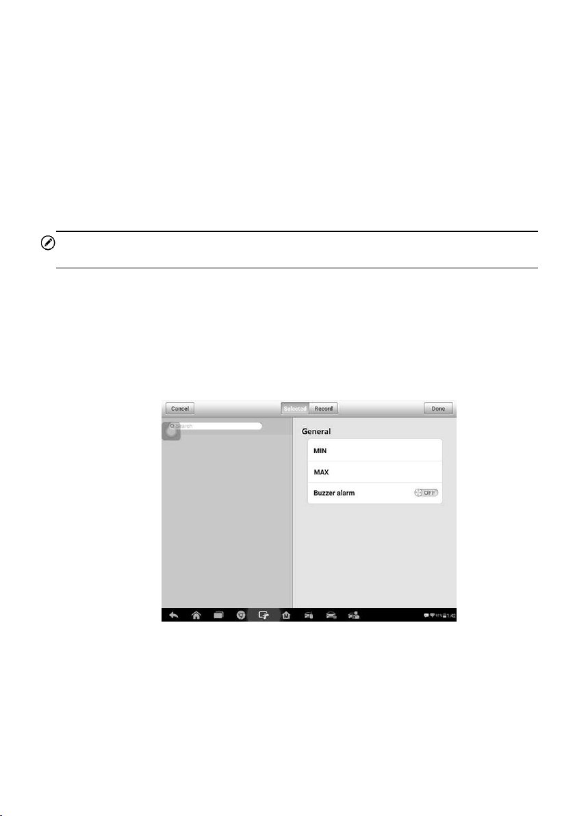
Figure 6-6 Sample Setting Mode in Live Data
There are four navigation buttons on top of the Setting mode screen.
Selected Button — displays the configuration screen on which you can set the
threshold values, an upper limit and a lower limit, for triggering the buzzer alarm.
This function is only applied to the Waveform Graph display mode.
a) MIN — tap button to open a virtual keyboard, allowing you to enter the required

42
lower limit value.
b) MAX — tap button to open a virtual keyboard, allowing you to enter the required
upper limit value.
c) Buzzer Alarm — switches the alarm on and off.
To set threshold limits for the parameter values
1. Tap the Setting function button at the bottom of the Live Data screen.
2. Tap the Selected navigation button.
3. Select a parameter item on the left column, or enter the item name in the Search
bar.
4. Tap on the right side of the MIN button, and enter the required minimum value.
5. Tap on the right side of the MAX button, and enter the required maximum value.
6. Tap the ON/OFF button on the right side of the Buzzer Alarm button to turn it on
or off.
7. Tap Done to save the setting and return to the Live Data screen; or tap Cancel
to exit without saving.
If the threshold limits are successfully set, two horizontal lines will appear on each of the
data graphs (when Waveform Graph Mode is applied) to indicate the alarming point. The
threshold lines are shown in different colors from the waveform of the parameters for
distinction.
Record Button — displays the configuration screen for Record Setting, on which
you can set the trigger type, duration and trigger point for the data recording function.
a) Trigger Type — sets the trigger mode for data recording, mainly of two kinds:
Manual and Auto. There are four options available:
1) Manual — allows you to manually start and stop data recording
2) DTC — auto triggers data recording when any DTC is detected
3) DTC Check Mode — auto triggers data recording when certain pre-
selected DTC types are detected
4) Parameter — auto triggers data recording when any parameter value
reaches the preset threshold
b) Duration — sets the recording time (for Auto trigger mode only)
c) Trigger Point — reserves a relative percentage of a record length before the
data recording start point for reference (for Auto trigger mode only)
To perform setting for live data record
1. Tap the Setting function button at the bottom of the Live Data screen.
2. Tap the Record navigation button.
3. Tap the button on the right of Trigger Type bar and select the required
trigger mode.
43
4. Tap the button on the right of Duration bar and select a length of time.
5. Tap the button on the right of Trigger Point bar and select a relative
percentage of a record length to be reserved before the data recording start
point.
6. Tap Done to save the setting and return to the Live Data screen; or tap Cancel
to cancel without saving and exit Setting.
Done Button — confirms and saves the setting, and returns to the Live Data screen.
Cancel Button — cancels the setting operation, and returns to the Live Data screen.
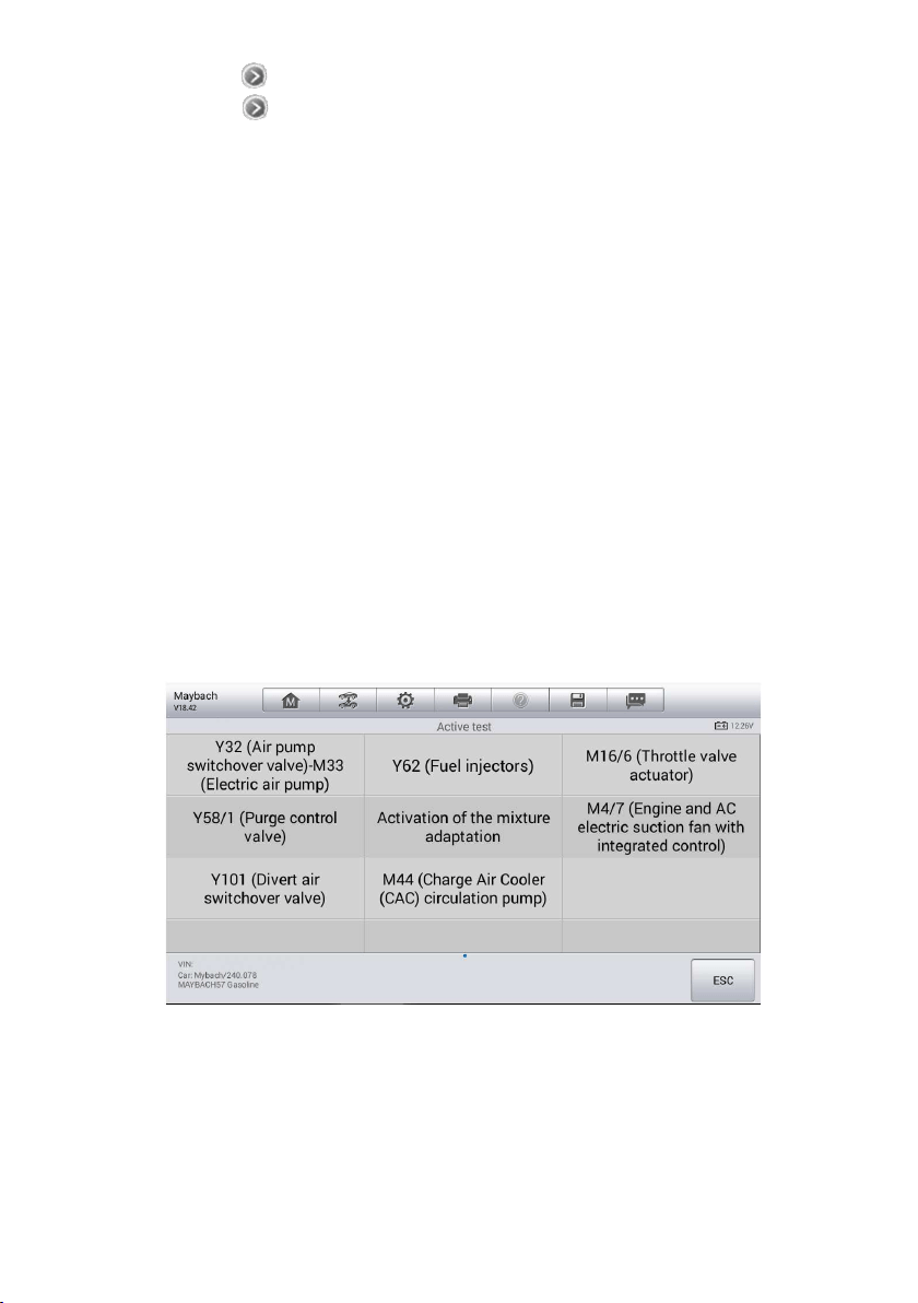
Active Test
The Active Test function is used to access vehicle-specific subsystem and component
tests. Available tests vary depending on the manufacturer, year, and model, and only the
available tests display in the menu.
During an active test, the tablet sends commands to the ECU in order to drive the actuators.
This test determines the integrity of the system or parts by reading the engine ECU data,
or by monitoring the operation of the actuators, such as switching a solenoid, relay, or
switch between two operating states.
Selecting Active Test opens a menu of test options that varies by make and model.
Selecting a menu option activates the test. Follow on-screen instructions while performing
tests. The content and pattern of the on-screen information vary according to the type of
test being performed. Some toggle and variable control tests display Active Test Controls
at the top of the screen with data stream information below, or vice versa.
The function buttons at the lower right corner of the Active Test screen manipulate the test
signals. The operational instructions are displayed on the main section of the test screen.
Simply follow the on-screen instructions and make appropriate selections to complete the
Figure 6-7 Sample Active Test Screen
44
tests. Each time when an operation is successfully executed, message such as
“Command Finished”, “Activation Successful”, or something similar displays.
Tap the ESC function button to exit the test when finished.
Special Functions
These functions perform various component adaptations, allowing you to recalibrate or
configure certain components after making repairs or replacement.
The main menu displays the supported special functions for the test vehicle. Follow the
on-screen instructions to complete the desired function. When the operation is done, an
execution status message such as Completed, Finished or Successful, displays. Tap the
ESC button to exit the function.
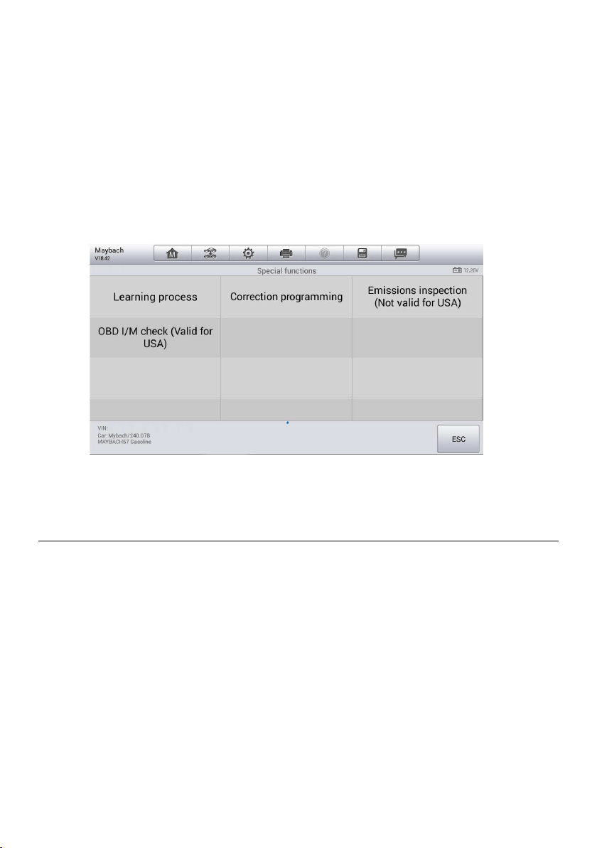
Generic OBDII Operations
A fast-access option for OBDII/EOBD vehicle diagnosis is available on the Vehicle Menu
screen. This option presents a quick way to check for DTCs, isolate the cause of an
illuminated malfunction indicator lamp (MIL), check monitor status prior to emissions
certification testing, verify repairs, and perform a number of other services that are
emissions-related. The OBD direct access option is also used for testing OBDII/EOBD
compliant vehicles that are not included in the Diagnostics database.
Functions of the diagnostics toolbar buttons at the top of the screen are the same as
those available for specific vehicle diagnostics. See
Table 4-2 Operation Toolbar Buttons
for details.
General Procedure
Figure 6-8 Sample Special Functions Screen

45
To access the OBDII/EOBD diagnostics functions
1. Tap the Diagnostics application button from the MaxiIM Job Menu. The Vehicle
Menu displays.
2. Tap the EOBD button. There are two options to establish communication with
the vehicle.
Auto Scan — when this option is selected the diagnostic tool attempts to
establish communication using each protocol in order to determine which
one the vehicle is broadcasting on.
Protocol — when this option is selected the screen opens a submenu of
various protocols. A communication protocol is a standardized way of data
communication between an ECM and a diagnostic tool. Global OBD may
use several different communication protocols.
3. Select a specific protocol under the Protocol option. Wait for the OBDII
Diagnostic Menu to appear.
NOTE
Tap the button beside the function name to display additional information.
4. Select a function option to continue.
DTC & FFD
I/M Readiness
Live Data
O
2
Sensor Monitor
On-Board Monitor
Component Test
Vehicle Information
Vehicle Status
NOTE
Some functions are supported only on certain vehicles.
Function Descriptions
This section describes the various functions of each diagnostic option:
DTC & FFD
When this function is selected, the screen displays a list of Stored Codes and Pending
Codes. When the Freeze Frame data of certain DTCs are available for viewing, a
snowflake button will display on the right side of the DTC item.

46
Figure 6-9 Sample DTC & FFD Screen
The erase codes function can be applied by tapping the Clear DTC button at the bottom
of the screen.
Stored Codes
Stored codes are the current emission related DTCs from the ECM of the vehicle.
OBDII/EOBD Codes have a priority according to their emission severity, with higher
priority codes overwriting lower priority codes. The priority of the code determines
the illumination of the Malfunction Indicator Light (MIL) and the codes erase
procedure. Manufacturers rank codes differently, so expect to see differences
between vehicles.
Pending Codes
These are codes whose setting conditions were met during the last drive cycle, but
need to be met on two or more consecutive drive cycles before the DTC actually
sets. The intended use of this service is to assist the service technician after a
vehicle repair and after clearing diagnostic information, by reporting test results after
a driving cycle.
a) If a test failed during the driving cycle, the DTC associated with that test is
reported. If the pending fault does not occur again within 40 to 80 warm-up
cycles, the fault is automatically cleared from memory.
b) Test results reported by this service do not necessarily indicate a faulty
component or system. If test results indicate another failure after additional
driving, then a DTC is set to indicate a faulty component or system, and the MIL
is illuminated.
Freeze Frame
In most cases the stored frame is the last DTC that occurred. Certain DTCs, which
have a greater impact on vehicle emission, have a higher priority. In these cases,
the top prioritized DTC is the one for which the freeze frame records are retained.
Freeze frame data includes a “snapshot” of critical parameter values at the time the
DTC is set.

47
Clear DTC
This option is used to clear all emission related diagnostic data such as, DTCs,
freeze frame data and manufacturer specific enhanced data from the vehicle’s ECM.
A confirmation screen displays when the clear codes option is selected to prevent
accidental loss of data. Select Yes on the confirmation screen to continue or No to
exit.
I/M Readiness
This function is used to check the readiness of the monitoring system. It is an excellent
function to use prior to having a vehicle inspected for compliance to a state emissions
program. Selecting I/M Readiness opens a submenu with two choices:
Since DTCs Cleared — displays the status of monitors since the last time the DTCs
are erased.
This Driving Cycle — displays the status of monitors since the beginning of the
current drive cycle.
Live Data
This function displays the real time PID data from ECU. Displayed data includes analog
inputs and outputs, digital inputs and outputs, and system status information broadcast
on the vehicle data stream.
Live data can be displayed in various modes, see
Live Data for detailed information.
O
2
Sensor Monitor
This option allows retrieval and viewing of O
2
sensor monitor test results for the most
recently performed tests from the vehicle’s on-board computer.
The O
2
Sensor Monitor test function is not supported by vehicles that communicate using
a controller area network (CAN). For O
2
Sensor Monitor tests results of CAN-equipped
vehicles, refer to
On-Board Monitor.
On-Board Monitor
This option allows you to view the results of On-Board Monitor tests. The tests are useful
after servicing or after erasing a vehicle’s control module memory.
Component Test
This service enables bi-directional control of the ECM so that the diagnostic tool is able
to transmit control commands to operate the vehicle systems. This function is useful in
determining whether the ECM responds to a command well.

48
Vehicle Information
The option displays the vehicle identification number (VIN), the calibration identification,
and the calibration verification number (CVN), and other information of the test vehicle.
Vehicle Status
This item is used to check the current condition of the vehicle, including communication
protocols of OBDII modules, retrieved codes amount, status of the Malfunction Indicator
Light (MIL), and other additional information.
Exiting Diagnostics
The Diagnostics application remains open as long as there is an active communication
with the vehicle. You must exit the diagnostics operation to stop all communications with
the vehicle before closing the Diagnostics application.
NOTE
Damage to the vehicle electronic control module (ECM) may occur if communication is
disrupted. Make sure all connections, such as USB cable and wireless connection, are
properly connected at all times during testing. Exit all tests before disconnecting the test
connection or powering down the tool.
To exit the Diagnostics application
1. From an active diagnostic screen, tap the Back or ESC function button to exit
a diagnostic session step-by-step.
2. Or tap the Vehicle Swap button on the diagnostics toolbar to return to the
Vehicle Menu screen.
3. From the Vehicle Menu screen, tap the Home button on the top toolbar; or tap
the Back button on the navigation bar at the bottom of the screen.
4. Or tap the Home button on the diagnostics toolbar to exit the application directly
and go back to the MaxiIM Job Menu.
Now, the Diagnostics application is no longer communicating with the vehicle and it is
safe to open other MaxiIM applications, or exit the MaxiIM Diagnostic System and return
to the Android System’s Home screen.

49
7. Service
The Service section is specially designed to provide you with quick access to the vehicle
systems for various scheduled service and maintenance performances. The typical
service operation screen is a series of menu driven executive commands. By following
the on-screen instructions to select appropriate execution options, enter correct values
or data, and perform necessary actions, the system will guide you through the complete
performance for various service operations.
The most commonly performed service functions include:
Oil Reset Service
EPB Service
BMS Service
SAS Service
DPF Service
TPMS Service
After entering each special function, the displayed screen consists of two applications:
Diagnosis and Hot Functions. The Diagnosis is for you to read/clear data since this is
necessary after some special functions. Hot Functions consists of sub functions of the
selected special function.
Oil Reset Service
This function allows you to perform reset for the Engine Oil Life system, which calculates
an optimal oil life change interval depending on the vehicle driving conditions and climate.
The Oil Life Reminder must be reset every time the oil is changed, so the system can
calculate when the next oil change is required.
IMPORTANT
Always reset the engine oil life to 100% after every oil change.
NOTE
All required work must be carried out before the service indicators are reset. Failure
to do so may result in incorrect service values and cause DTCs to be stored by the
relevant control module.
For some vehicles, the scan tool can perform added functionality to reset additional
service lights (maintenance cycle, service interval). Taking BMW as an example, its
service reset function includes engine oil, spark plugs, front/rear brakes, coolant,
particle filter, brake fluid, micro filter, vehicle inspection, exhaust emission inspection
and vehicle check.
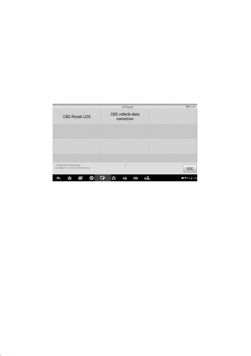
50
All software screens shown in this manual are examples, actual test screens may vary
for each vehicle being tested. Observe the menu titles and on-screen instructions to
make correct option selections.
To perform oil reset functions
1. Tap the Service application button from the MaxiIM Job Menu.
2. Tap Oil Reset button and wait for the vehicle manufacturer screen. You can tap
VIN Scan or the vehicle make to acquire vehicle VIN information and tap Yes
to confirm. See Vehicle Identification for details.
3. Tap the function you want in the Oil Reset function list, the list may vary for
different vehicles being tested.
4. Follow the step-by-step on-screen instruction to complete the service. Take CBS
Reset UDS as an example.
5. Tap CBS Reset UDS on the Oil Reset function list to start the operation. The
screen will guide you to confirm the date and time, if the displayed date and time
are correct, tap Yes to confirm. If not, tap No and go to the Settings menu to set
the correct date and time.
Figure 7-1 Sample Oil Reset Function List
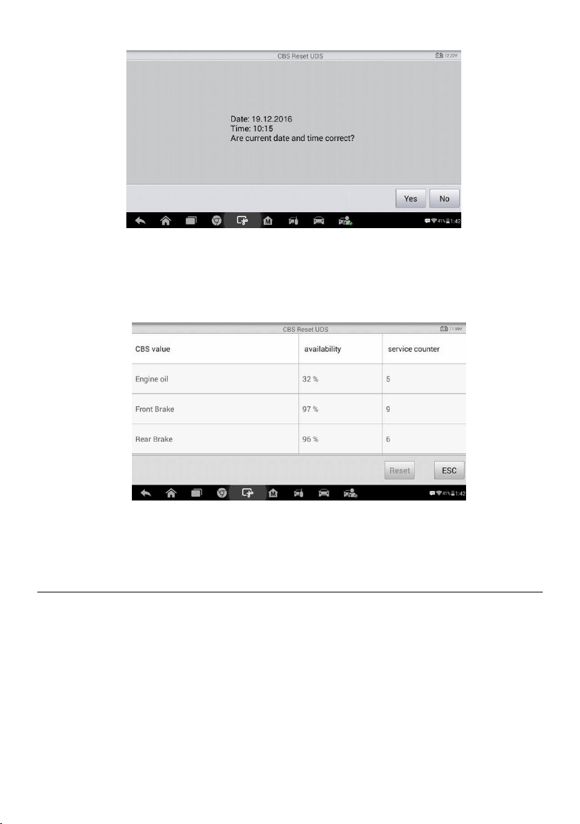
51
Figure 7-2 Sample Oil Reset Service Screen 1
6. On the next screen, the available items would be listed with three columns
displayed: CBS value, availability, and service counter.
7. Tap on the value you want to reset and then tap the Reset button on the right
bottom of the screen.
8. When the reset is done, the availability would display as 100%. Tap ESC to exit.
Electronic Parking Brake (EPB) Service
This function has a multitude of usages to maintain the electronic braking system safely
and effectively. The applications include deactivating and activating the brake control
system, assisting with brake fluid control, opening and closing brake pads, and setting
brakes after disc or pad replacement, etc.
Figure 7-3 Sample Oil Reset Service Screen 2
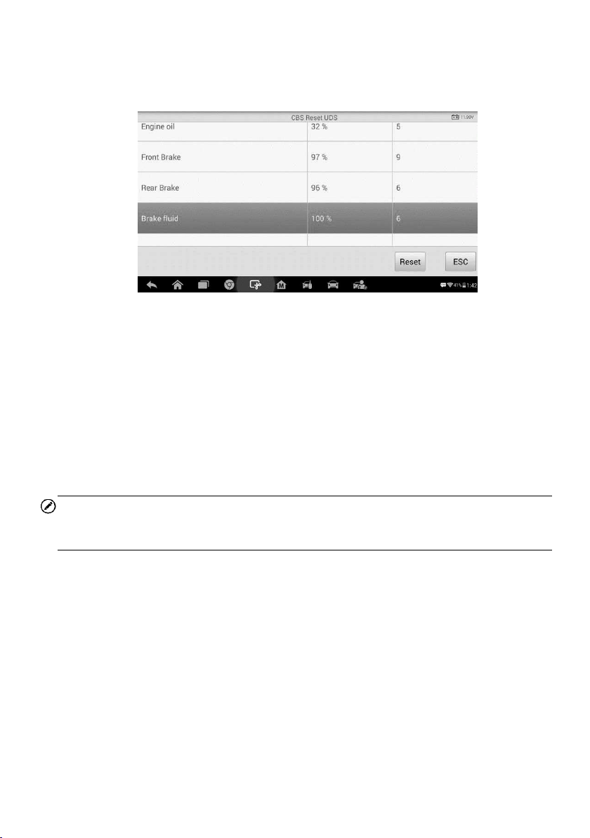
52
EPB Safety
It may be dangerous to perform Electronic Parking Brake (EPB) system maintenance, so
before you begin the service work, please keep these rules in mind.
Ensure that you are fully familiar with the braking system and its operation before
commencing any work.
The EPB control system may be required to be deactivated before carrying out any
maintenance/diagnostic work on the brake system. This can be done from the tool
menu.
Only carry out maintenance work when the vehicle is stationary and on level ground.
Ensure that the EPB control system is reactivated after the maintenance work has
been completed.
NOTE
Autel accepts no responsibility for any accident or injury arising from the maintenance of
the Electronic Parking Brake system.
To perform EPB functions
1. Tap the Service application button from the MaxiIM Job Menu.
2. Tap EPB button and wait for the vehicle manufacturer screen. You can tap VIN
Scan or the vehicle make to acquire vehicle VIN information and tap Yes to
confirm. See
Vehicle Identification for details.
Figure 7-4 Sample Oil Reset Service Screen 3
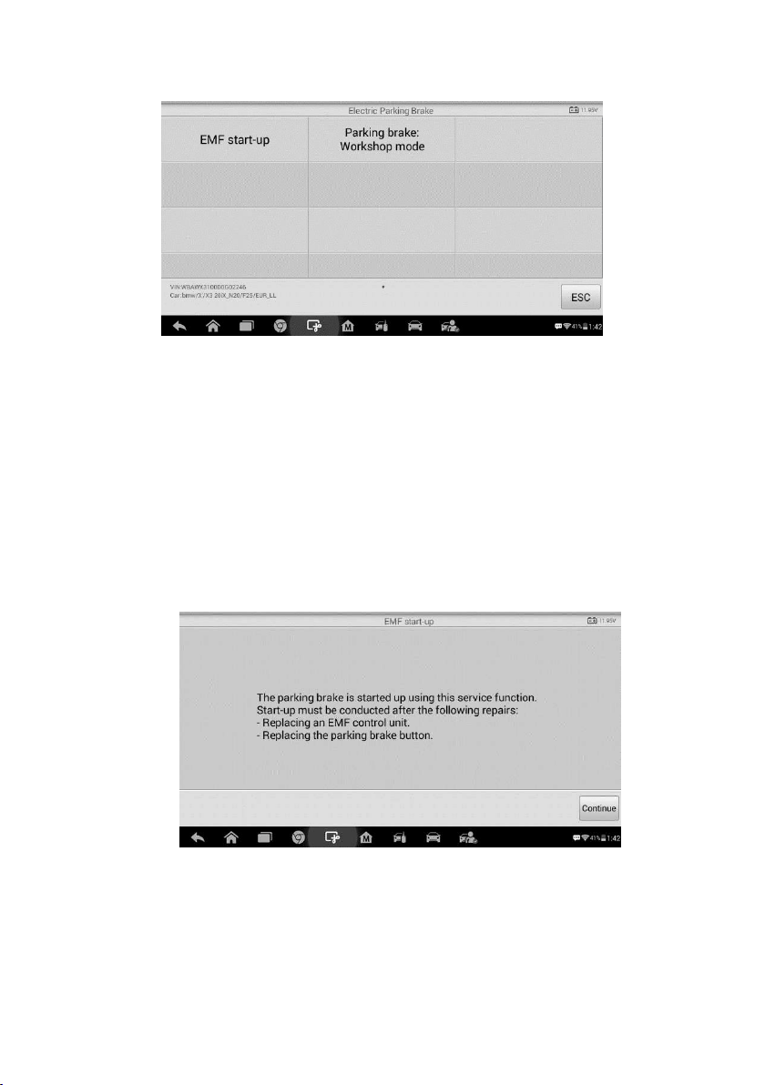
53
3. Tap the service you want in the EPB function list, the list may vary for different
vehicles being tested.
4. Follow the step-by-step on-screen instruction to complete the service.
5. Press OK button to exit.
EMF Start-up
This service function would start up the parking brake, it must be conducted after the
following repairs:
Replacing an EMF control unit.
Replacing the parking brake button.
1) Tap Continue to proceed this service function or the Back button at the bottom left
to exit.
Figure 7-5 Sample EPB Function List
Figure 7-6 Sample EMF Start-up Screen 1
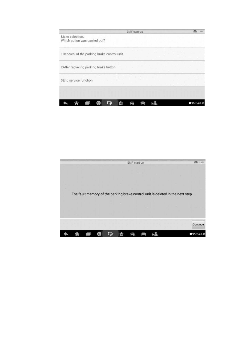
54
2) Tap on the action that has been carried out to continue.
3) In the following step, the screen will remind you that the fault memory of the parking
brake control unit will be deleted, press Continue to proceed or the Back button to
exit.
4) Follow the on-screen instructions to pull the parking brake button and wait for around
3 seconds until the parking brake is set. When the operation is successfully
completed, a “Completed successfully” message will appear on the screen. Press
“OK” to exit.
Parking Brake: Workshop Mode
This service is used to activate and deactivate the so-called installation position for the
Automatic Hold brake. In this mode the parking brake is moved into the opened position
and temporarily deactivated for personal protection.
The installation position must be activated for the following repairs:
Figure 7-7 Sample EMF Start-up Screen 2
Figure 7-8 Sample EMF Start-up Screen 3

55
Replacement of brake pads.
Replacement of a brake caliper.
Replacement of an actuator.
Select Parking Brake: Workshop Mode and follow the on-screen instructions to
perform a series of operations to start the brake pad after replacement.
When the operation is successfully completed, a “Completed successfully” message will
appear on the screen. Press OK to exit.
BMS
The BMS (Battery Management System) allows the scan tool to evaluate the battery
charge state, monitor the close-circuit current, register the battery replacement, and
activate the rest state of the vehicle.
NOTE
1. This function is not supported by all vehicles. The screens shown in this section are
examples.
2. The sub functions and actual test screens of the BMS may vary for different test
vehicles, please follow the on-screen instructions to make correct option selection.
The vehicle may use either a sealed lead-acid battery or an AGM (Absorbed Glass Mat)
battery. Lead acid battery contains liquid sulphuric acid and can spill when overturned.
AGM battery (known as VRLA battery, valve regulated lead acid) also contains sulphuric
acid, but the acid is contained in glass mats between terminal plates.
It is recommended that the replacement aftermarket battery has the same specifications,
such as capacity and type, with the battery used in the vehicle. If the original battery is
replaced with a different type of battery (e.g. a lead-acid battery is replaced with an AGM
battery) or a battery with a different capacity (mAh), the vehicle may require
reprogramming the new battery type in addition to performing the battery reset. Consult
the vehicle manual for additional vehicle-specific information.
Register Battery Replacement
This option allows displaying the mileage reading of last battery replacement, registering
the battery replacement after replacing a new battery and informing the power
management system that a new battery has been fitted to the vehicle.
If the battery change is not registered, the power management system will not function
properly, which may not provide the battery with enough charging power to operate the
car and limit the functions of individual electrical equipment.
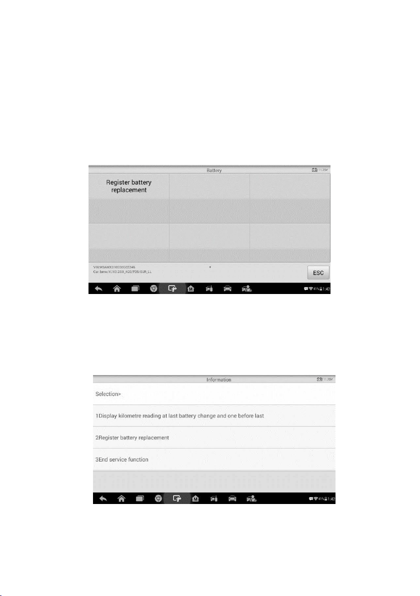
56
Take BMW as an example.
To display the battery history
1. Tap the Service application button from the MaxiIM Job Menu.
2. Tap BMS button and wait for the vehicle manufacturer screen. You can tap VIN
Scan or the vehicle make to acquire vehicle VIN information and tap Yes to
confirm. See
Vehicle Identification for details.
3. Tap Register Battery Replacement in the EPB function list, the list may vary
for different vehicles being tested.
4. Tap on the corresponding service you want to carry out. In this case, it is function
1 Display kilometer reading at last battery change and one before last. A
notice screen displays.
Figure 7-9 Sample BMS Function List
Figure 7-10 Sample BMS Screen 1
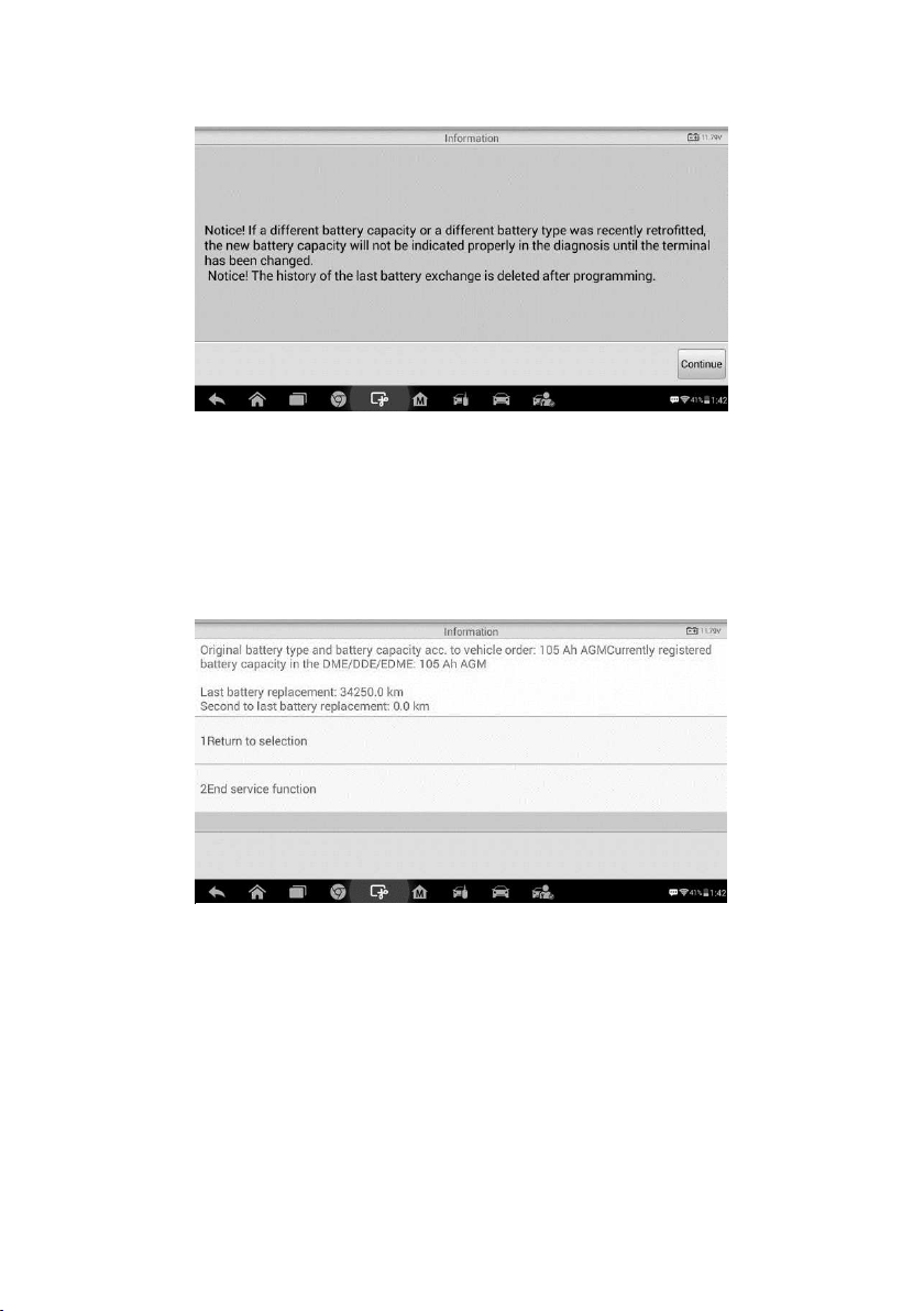
57
5. Read carefully the complete information and press Continue to continue.
6. Check the battery capacity and the battery replacement information on the
screen.
7. Tap on the corresponding function 1 to return to the selection screen or press
the function 2 to end the service function.
Figure 5-12
Figure 7-11 Sample BMS Screen 2
Figure 7-12 Sample BMS Screen 3
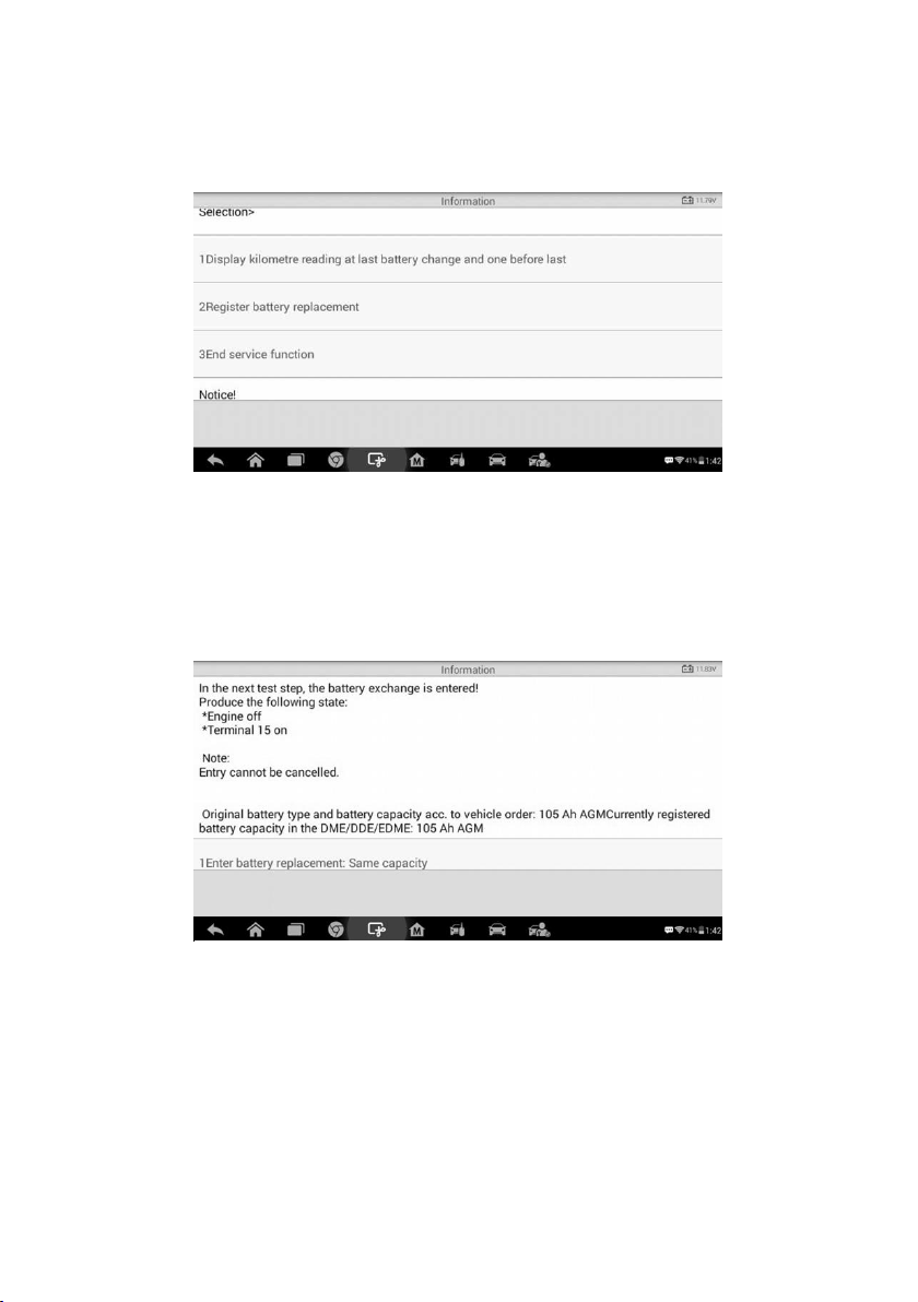
58
To register the battery replacement
1. Tap on the corresponding service you want to carry out. In this case, it is function
2 Register battery replacement.
2. Read carefully the information on the screen and slide up/down to view all the
functions listed.
There are four functions listed:
1) Enter battery replacement: Same capacity
2) Enter battery replacement: Different capacity
3) Enter battery replacement: Changing from the normal lead-acid battery
(white housing) to AGM battery (black housing)
4) End service function.
Figure 5-13
Figure 7-13 Sample BMS Screen 4
Figure 7-14 Sample BMS Screen 5
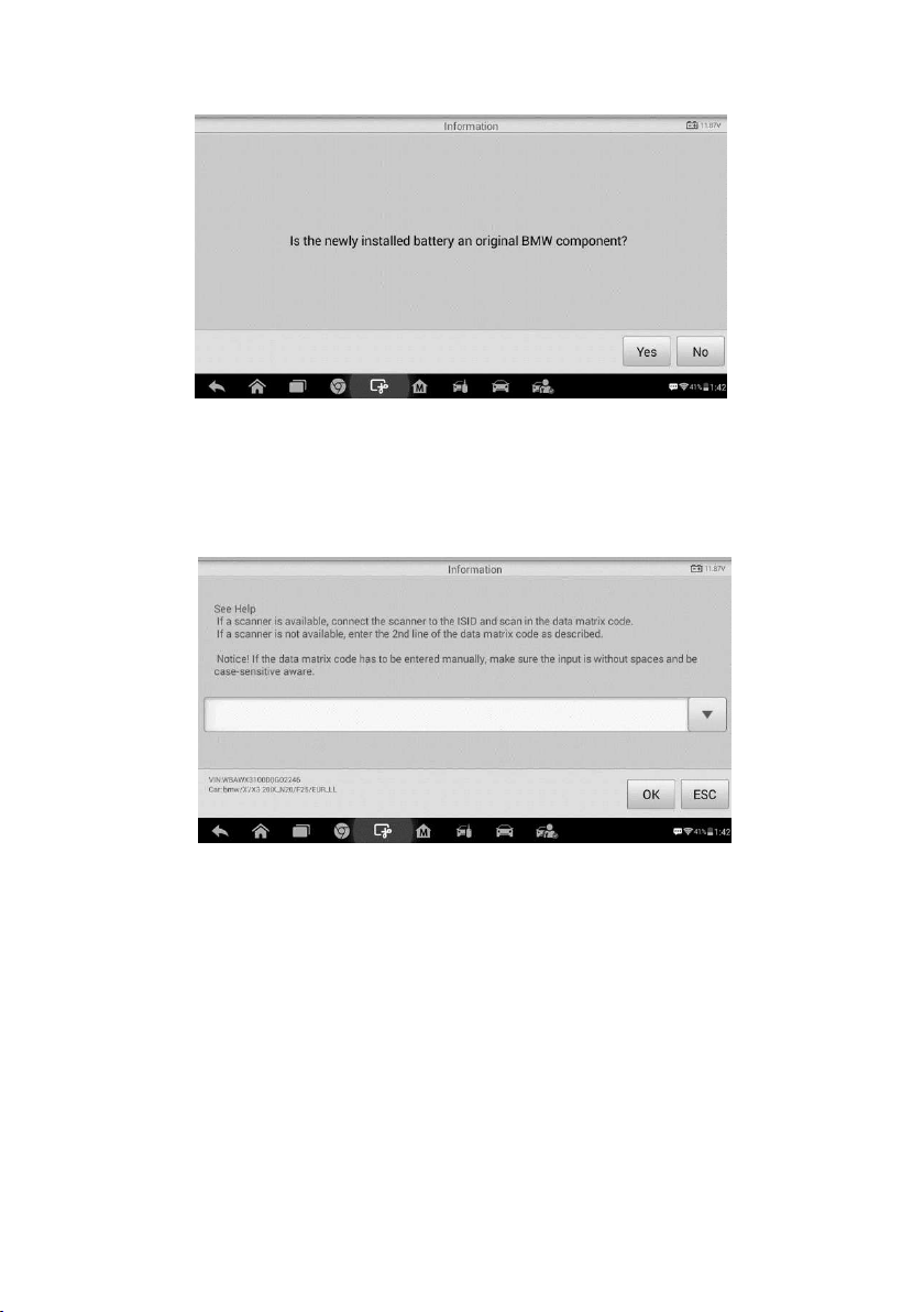
59
Take the first function as an example.
1. Read carefully the information on the screen and tap Yes to continue.
2. Follow the on-screen instructions to input the data matrix code of the newly installed
battery which should be on the label of the battery. Tap OK to continue.
3. When the battery exchange is successfully entered, tap Continue to complete the
operation.
Figure 7-15 Sample BMS Screen 6
Figure 7-16 Sample BMS Screen 7
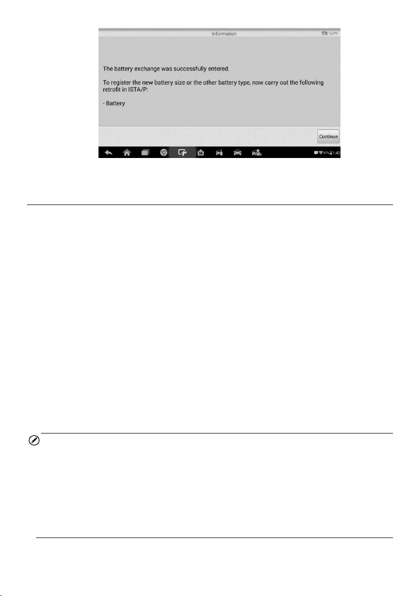
60
Steering Angle Sensor (SAS) Service
Steering Angle Sensor Calibration permanently stores the current steering wheel position
as the straight-ahead position in the steering angle sensor EEPROM. Therefore, the front
wheels and the steering wheel must be set exactly to the straight-ahead position before
calibration. In addition, the vehicle identification number is also read from the instrument
cluster and stored permanently in the steering angle sensor EEPROM. On successful
completion of calibration, the steering angle sensor fault memory is automatically cleared.
Calibration must always be carried out after the following operations:
Steering wheel replacement
Steering angle sensor replacement
Any maintenance that involves opening the connector hub from the steering angle
sensor to the column
Any maintenance or repair work on the steering linkage, steering gear or other
related mechanism
Wheel alignment or wheel track adjustment
Accident repairs where damage to the steering angle sensor or assembly, or any
part of the steering system may have occurred
NOTE
Autel accepts no responsibility for any accident or injury arising from servicing the
SAS system. When interpreting DTCs retrieved from the vehicle, always follow the
manufacturer’s recommendation for repair.
All software screens shown in this manual are examples, actual test screens may
vary for each vehicle being tested. Observe the menu titles and on-screen
instructions to make correct option selections.
Before starting the procedure, make sure the vehicle has an ESC button. Look for
the button on dash.
Figure 7-17 Sample BMS Screen 8
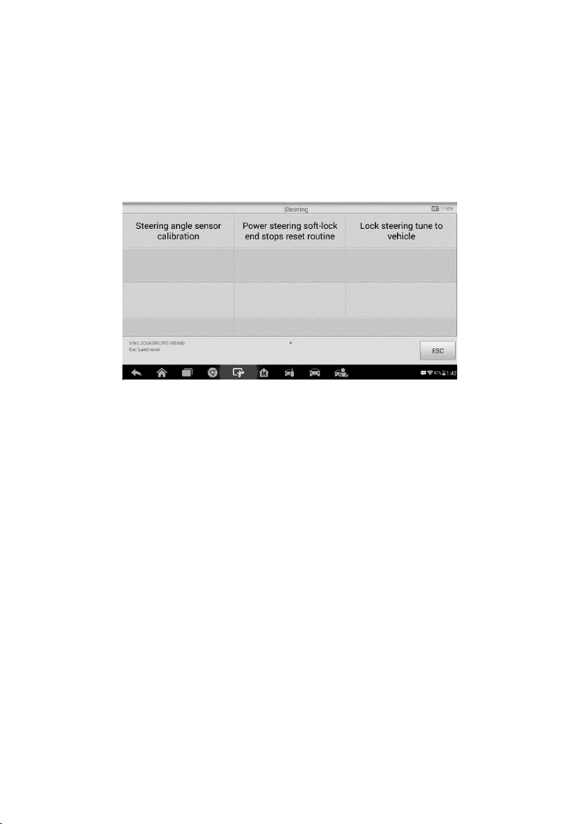
61
Take Land Rover as an example.
1. Tap the Service application button from the MaxiIM Job Menu.
2. Tap SAS button and wait for the vehicle manufacturer screen. You can tap VIN Scan
or the vehicle make to acquire vehicle VIN information and tap Yes to confirm. See
Vehicle Identification for details.
3. Tap the service you want in the SAS function list, the list may vary for different
vehicles being tested.
Steering Angle Sensor Calibration
This function allows users to perform steering angle sensor calibration and clear records.
The function options vary with the vehicles being tested.
1) Tap Steering Angle Sensor Calibration from the SAS function menu to enter the
function screen.
2) Follow the on-screen instructions to set the ignition on/off as guided. The vehicle
battery voltage signal should be in the range 12.5 – 13.5 volts to proceed this service,
otherwise the scan tablet will display a warning message.
Figure 7-18 Sample SAS Function Menu
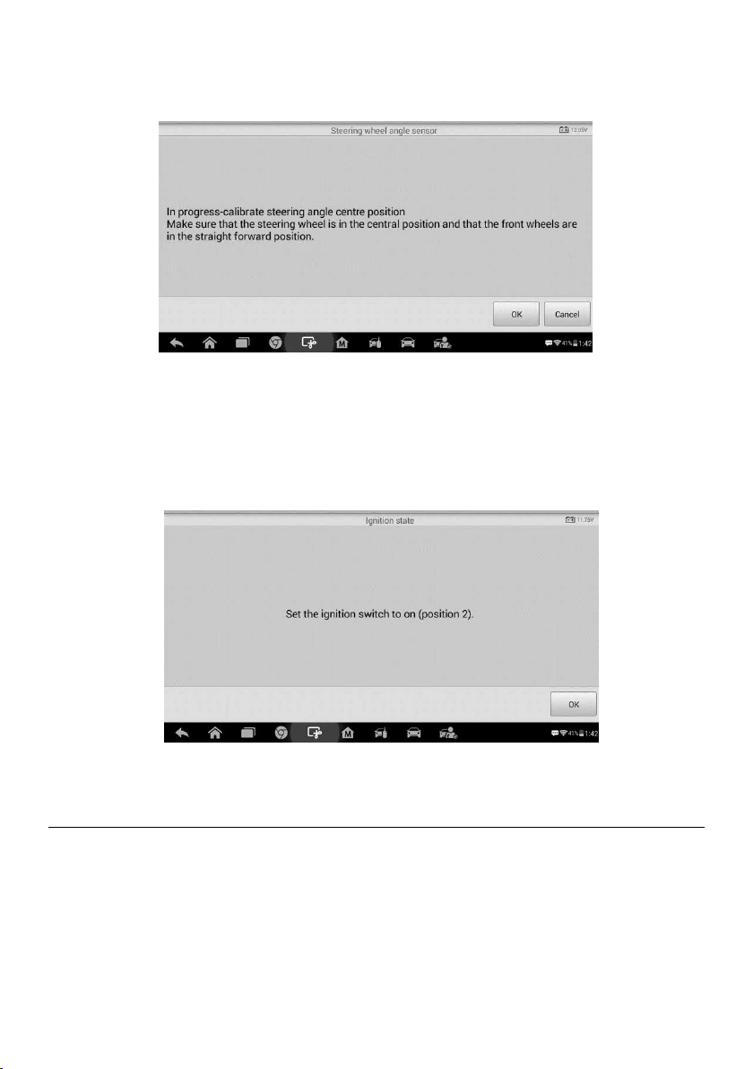
62
3) Make sure the steering wheel is in the central position and the front wheels are in
the straight position. Then tap OK to proceed.
4) When the operation is completely finished, the scan tool will display a confirmation
message. Otherwise, it will display a message to remind you of a problem. After you
exit the diagnosis program, please repair the problem immediately.
DPF Service
The DPF function allows you to carry out numerous functions to the Diesel Particulate
Filter system without having to send your car to a main dealer. The tool will manage DPF
regeneration, DPF component replacement teach-in and DPF teach-in after replacing
the engine control unit.
ECM monitors driving style and selects a suitable time to employ regeneration. Cars
driven a lot at idling speed and low load will attempt to regenerate earlier than cars driven
Figure 7-19 Sample SAS Function Screen 1
Figure 7-20 Sample SAS Function Screen 2
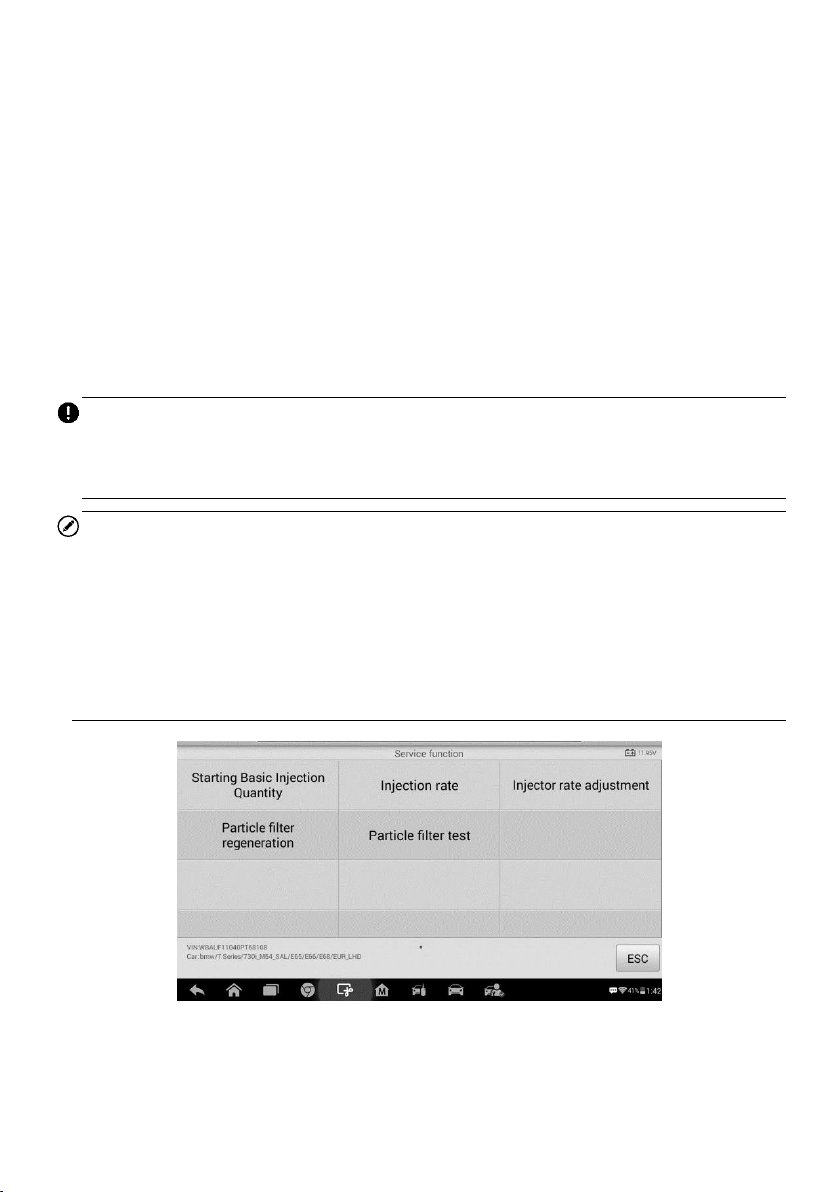
63
more with high load and high speed. In order for regeneration to take place, a prolonged
high exhaust temperature must be obtained.
In the event of the car being driven in such a way that regeneration is not possible, i.e.
frequent short journeys, a diagnostic trouble code will eventually be registered, DPF light
and “Check Engine” indicator comes on. A service regeneration can be requested in the
workshop, using the diagnostic tool.
Before carrying out a forced DPF regeneration using the tool, check the following items:
The fuel light is not on.
No DPF-relevant faults stored in system.
The vehicle has the correct spec engine oil.
The oil for diesel is not contaminated.
IMPORTANT
Before diagnosing a problem vehicle and attempting to perform an emergency
regeneration, it is important to obtain a full diagnostic log and read out relevant measured
value blocks.
NOTE
The DPF will not regenerate if the engine management light is on, or there is a faulty
EGR valve.
The ECU must be re-adapted when replacing the DPF and when topping up the fuel
additive Eolys.
If the vehicle needs to be driven in order to perform a DPF service, ALWAYS have a
second person help you. One person should drive the vehicle while the other person
observes the screen on the Tool. Trying to drive and observe the Scan Tool at the
same time is dangerous, and could cause a serious traffic accident.
Figure 7-21 Sample DPF Service Function Menu
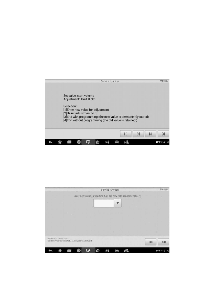
64
Starting Basic Inspection Quantity
This function enables you to start fuel delivery matching.
1. Tap Starting Basic Inspection Quantity from the service functions menu to enter
the service screen.
2. The tool communicates with the vehicle and reads the fault codes memory. Follow
the on-screen instructions to finish this procedure.
3. The tool will display a function list menu as below. Press the corresponding number
button to perform the desired function.
[1] Enter New Value for Adjustment
From the Starting Basic Inspection Quantity menu, tap [1] and the screen displays as
below.
After entering the value, tap OK to save the value to the tool. Tap ESC to exit the
operation.
Figure 7-22 Sample Starting Basic Inspection Quantity
Figure 7-23 Sample Enter New Value Screen
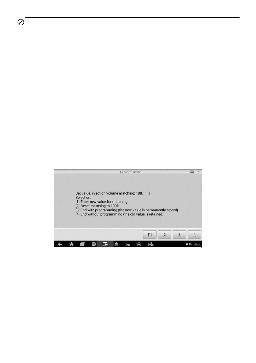
65
NOTE
The data you input should be in the range given. If the input data is out of range, the tool
will display a warning message “Permissible adjustment range exceeded.”
[2] Reset Adjustment to 0
Once the [2] is tapped, the tool will automatically reset the value to zero.
[3]/[4] Store Data and Exit
When the fuel delivery rate adjustment is completed, tap [3] to store the new value in the
control units; or select [4] and OK to retain the old value.
Injection Rate
This function is used to adjust the injection volume.
1. Tap Injection Rate from the service functions menu to enter the service screen.
2. The tool communicates with the vehicle and reads the fault codes memory. Follow
the on-screen instructions to finish this procedure.
3. Then the tool will display as below. Press the corresponding number button to
perform the desired function.
[1] Enter New Value for Matching
Figure 7-24 Sample Injection Rate Screen
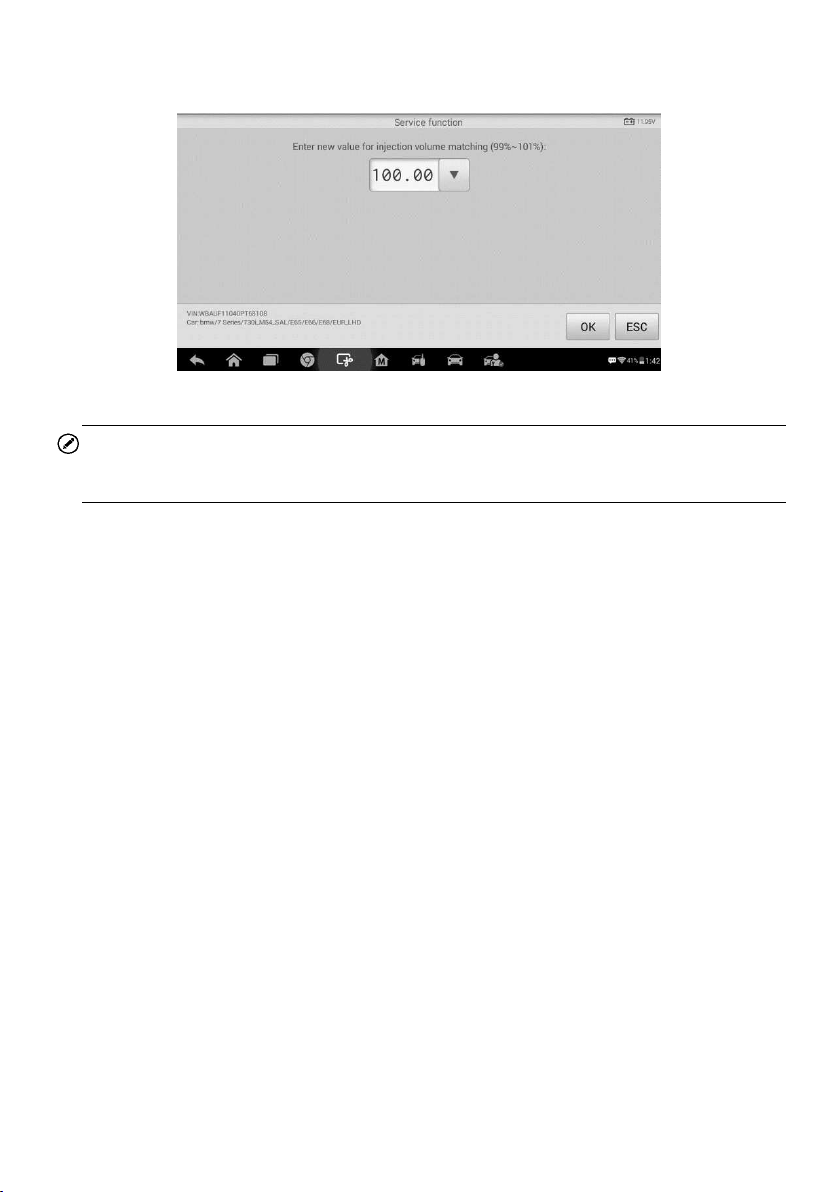
66
From the Injection Rate menu, tap [1] and the screen displays as below.
NOTE
The data you input should be in the reasonable range. If the input data is out of range,
the tool will display a warning message “Permissible adjustment range exceeded.”
[2] Reset Matching to 100%
Once the [2] is pressed, the tool will automatically reset the value to 100%.
[3]/[4] Store Data and Exit
When the injection volume adjustment is completed, select [3] and OK to store the new
value in the control units; or select [4] and OK to retain the old value.
Injector Rate Adjustment
This function is used to adjust the injector rate for individual cylinders.
1. Tap Injection rate adjustment from the service functions menu.
2. The tool communicates with the vehicle and reads the fault codes memory. Follow
the on-screen instructions to enter the service function.
3. Tap the corresponding number button to enter new value for each cylinder.
4. Follow the on-screen instructions to tap on the corresponding number [1] [2] [3] [4]
to enter the new value for the cylinder, restore the old value, and exit after finish the
function.
Particle Filter Regeneration
This function is used to perform the particle filter regeneration.
1. Tap Particle filter regeneration from the service functions menu.
Figure 7-25 Sample Enter Value Screen
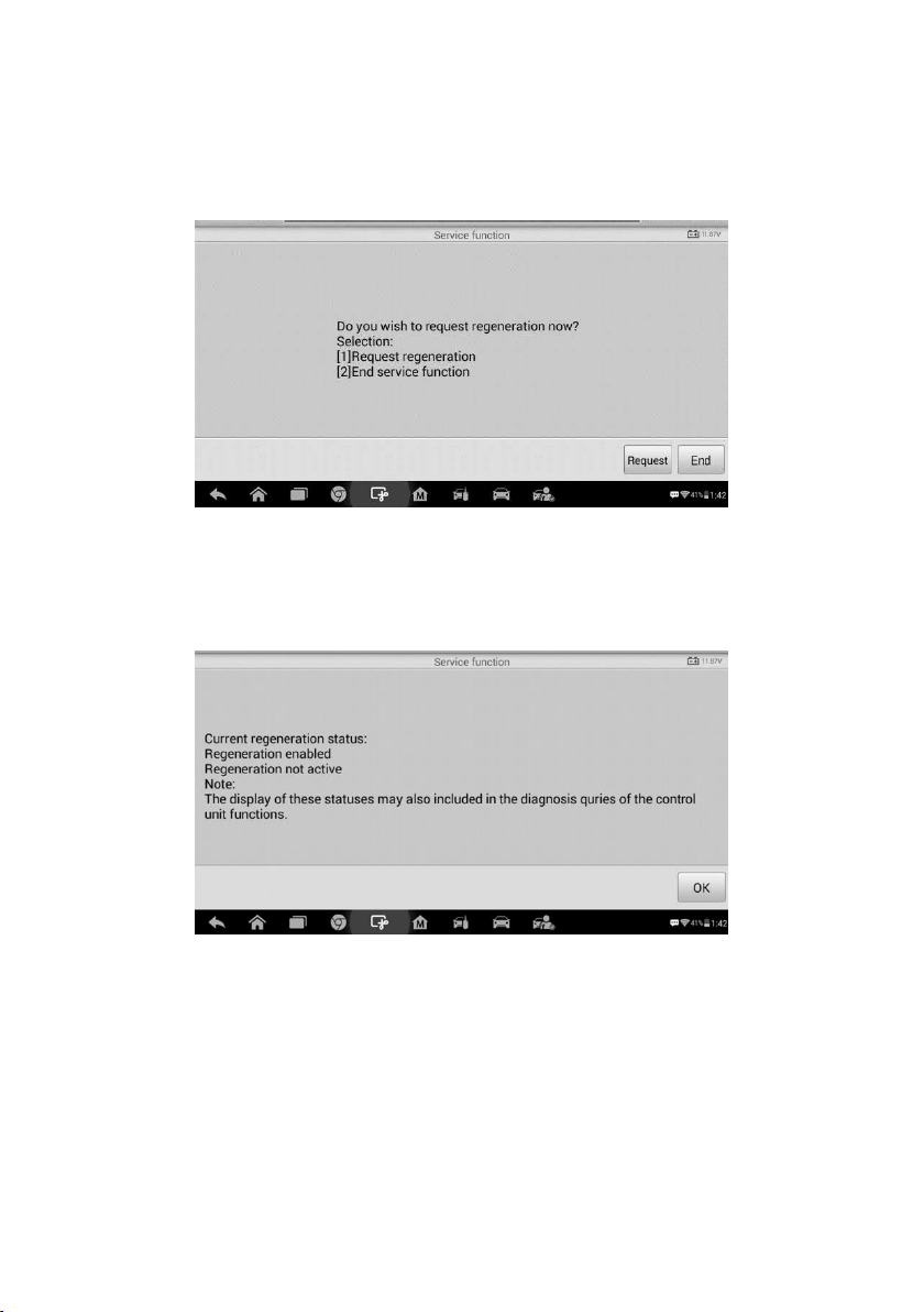
67
2. The tool communicates with the vehicle and reads the fault codes memory. Follow
the on-screen instructions to check the prerequisites before particle filter
regeneration, such as the fuel, the time and driving style.
3. If every prerequisite is met, the tool will ask your confirmation to proceed as below.
Tap Request to begin a regeneration or End to end the service function and exit.
4. A series of instruction screens appears for users to perform the particle filter
regeneration step by step. Follow the onscreen instructions and tap OK button until
the tool reads off the regeneration status as below.
5. When the particle filter regeneration is complete, the tool will ask your confirmation
to exit the display. Tap Repeat to check the status again or End to end the service
function and exit.
Figure 7-26 Sample Regeneration Confirmation Screen
Figure 7-27 Sample Regeneration Status Screen
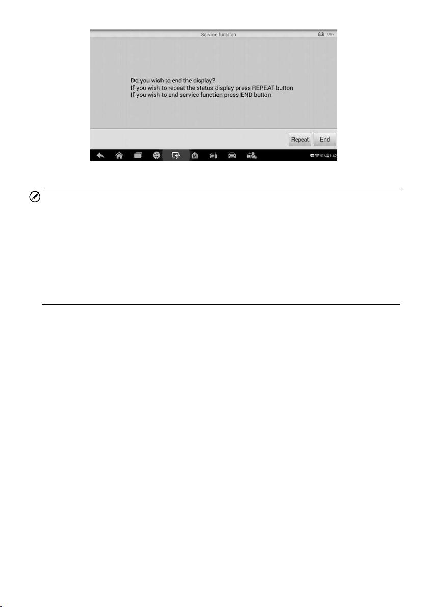
68
NOTE
In the case of a particle filter heavily loaded with soot, it can occur that the regeneration
request is blocked again after a short time or is not released. In this case, it is required
to regenerate the particle filter in a motorway or cross-country trip taking approx. 30
minutes at a speed that is as constant as possible. Subsequently, the service function
“Particle filter regeneration” must be run again.
During the regeneration phase and with the engine running, it can also occur that the
display for “Regeneration active” jumps to “Regeneration not active”. This behavior can
be seen exclusively with the vehicle stationary with the engine.
Particle Filter Test
It is advisable to carry out a series of particle filter tests as a result of constant DPF
regeneration, such as checking oil level, oil change interval for diesel contamination, swirl
flaps, backpressure sensors and particle filter soot remains.
1. Tap Particle filter test from the service functions menu.
2. The tool communicates with the vehicle and reads the fault codes memory. If there
is no relevant fault code stored in DDE, the screen displays as below. Select Cancel
to exit this function.
3. If there are DPF-related codes stored in DDE, the screen displays as below. Select
OK to continue or Cancel to exit this function.
Figure 7-28 Sample Repeat Screen
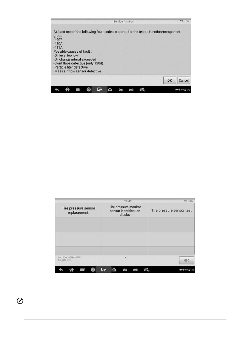
69
4. The tool shows a list of particle filter test. Select the corresponding number button
to perform the desired test [1] [2] [3] [4] [5].
[1] Visual Inspection of Engine Oil
[2] Visual Inspection of Particulate Filter
[3] Function Check or Swirl Flaps
[4] Exhaust Backpressure Test
[5] Actual/Target Value Check-Mass Air Flow Sensor
Tire Pressure Monitor System (TPMS) Service
This function allows you to quickly look up the tire sensor IDs from the vehicle’s ECU, as
well as to perform TPMS replacement and sensor test.
Figure 7-30 Sample TPMS Function Menu
Take Tire pressure sensor replacement (Front left wheel sensor) as an example.
NOTE
During this application the wheel unit 8 digit identifications will need to be entered using
the screen displayed.
Figure 7-29 Sample Codes Screen
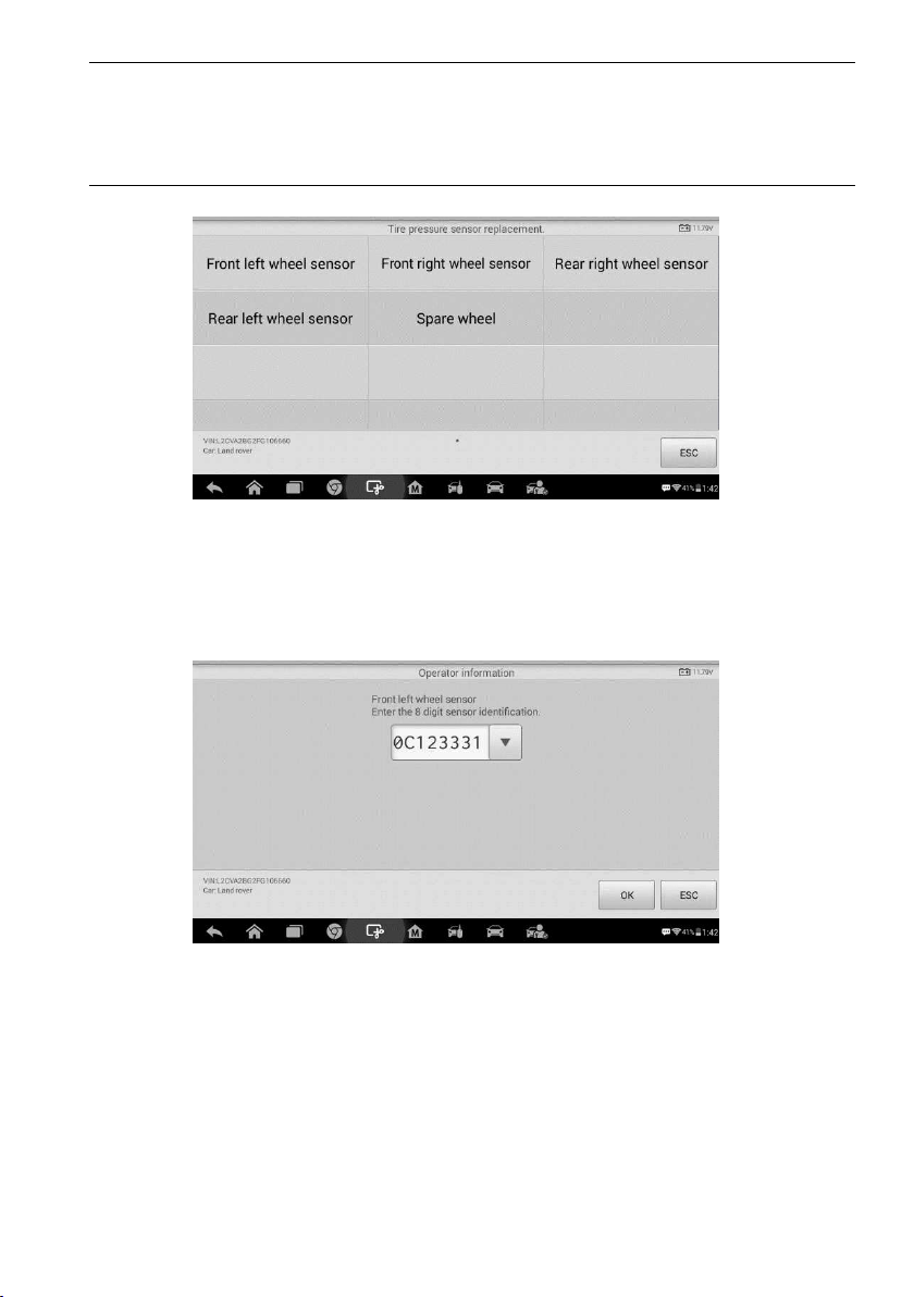
70
The sensor identifications can be accessed by reading directly from the wheel unit or by
using the identification reading tool.
On completion, a specific road test will be required followed by the tire pressure monitor
system application.
1) Tap Front left wheel sensor in the tire pressure sensor replacement menu.
2) Enter the 8 digit sensor identification as required.
3) The scan tablet will carry out the service and the screen will remind you the test has
passed and all the selected tire pressure sensor identification numbers programmed
successfully.
Figure 5-31
Figure 5-32
Figure 7-31 Sample Tire Pressure Sensor Replacement Screen
Figure 7-32 Sample Sensor ID Input Screen

71
NOTE
The vehicle must remain stationary for at least 15 minutes with the ignition off, this will
place the sensors into sleep mode. The vehicle must be driven for at least 15 minutes at
a speed higher than 20 kph to ensure the module has learnt the sensor identifications
and positions.
For other services, please follow the on-screen instructions to operate.
On completion of the drive cycle, carry out the tire pressure monitor system test
application.
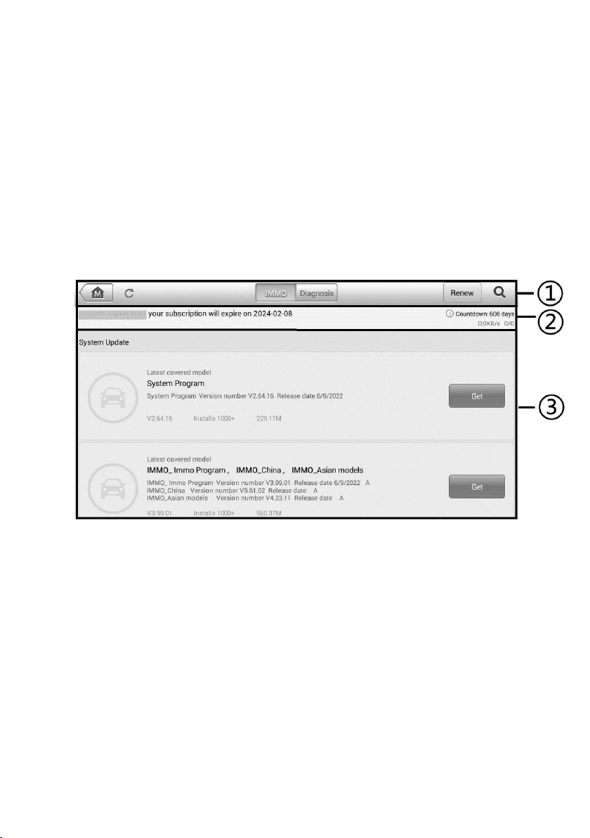
72
8. Update
The Update application allows you to download the latest released software. The updates
can improve the MaxiIM applications’ capabilities, typically by adding new tests, new
models, or enhanced applications to the database.
The tablet automatically searches for available updates for all of the MaxiIM software
when it is connected to the Internet. Any updates that are found can be downloaded and
installed on the device. This section describes installing an update to the MaxiIM System.
A notification message displays if an update is available when the Notifications Center
function is enabled in the Settings application.
1. Navigation and Controls
Home Button — returns to the MaxiIM Job Menu.
Refresh — refreshes the available update list.
IMMO Tab — displays all available IMMO software for vehicles.
Diagnostics Tab — displays all available vehicle diagnostics software.
Renew — renews the subscription.
Search Bar — search specific update item by inputting the file name, for
example: a specific vehicle manufacturer.
2. Status Bar
Left Side — displays your account email address and expiration date of your
subscription.
Figure 8-1 Sample Update Screen

73
Right Side — shows the remaining days of your subscription and real-time
Internet speed amid downloading.
3. Main Section
Left Column — displays vehicle logos.
Middle Column — displays a brief introduction about the new changes to the
software operation or capabilities.
Right Column — according to the operation status of each software item, the
button displays differently.
Tap the sort type button to sort available items in desired type.
Tap Bulk update to batch update selected items.
Tap Get to update the item.
Tap Pause to suspend the update.
Tap Continue to resume the update.
To update the IMMO software and diagnostic software
1. Make sure the tablet is connected to a power source with stable access to the
Internet.
2. Tap the Update application button from the MaxiIM Job Menu; or tap the
update notification message when received one; or tap the Update icon on
Vehicle Menu in IMMO/Diagnostics application. The Update application screen
displays.
3. Check all available updates and select the desired tab:
If you decide to update all the items, tap Bulk update > Select all.
If you decided to update more than one items, tap the Bulk update button
and selected the desired items.
If you only want to update one item, tap the Get button on the right column
of the item.
4. Tap the Pause button to suspend the updating process. Tap Continue to
resume the update and the process will continue from the pause point.
5. When the updating process is completed, the firmware will be installed
automatically. The new version will replace the older version.

74
9. Settings
Selecting Settings application opens a setup screen, on which you can adjust default
setting and view information about the MaxiIM system. The following shows options
available for the MaxiIM system settings:
Unit
Language
Printing Settings
Report Settings
Firmware Upgrade
Multitask
Auto Update
Car Order
System Settings
About
This section describes the operation procedures for the settings.
Unit
This option allows you to adjust the measurement unit for the diagnostic system.
To adjust the unit setting
1. Tap the Settings application on the MaxiIM Job Menu.
2. Tap the Unit option on the left column.
3. Select the required measurement unit, Metric or Imperial. A check mark will
display to the right of the selected unit.
4. Tap the Home button on the top left corner to return to the MaxiIM Job Menu.
Or select another setting option for system setup.

75
Language
This option allows you to adjust the display language for the MaxiIM system.
To adjust the language setting
1. Tap the Settings application on the MaxiIM Job Menu.
2. Tap the Language option on the left column.
3. Select the required language. A check mark will display to the right of the
selected language.
4. Tap the Home button on the top left corner to return to the MaxiIM Job Menu.
Or select another setting option for system setup.
Printing Settings
This option allows you to print any data or information anywhere and anytime via Wi-Fi
connection.
To setup the printer connection
1. Tap the Settings application on the MaxiIM Job Menu.
2. Tap the Printing Settings option on the left column.
3. Tap the Print via Network item to activate the printing function, which enables
the device to send files to the printer through the PC via Wi-Fi connection.
4. Tap the Home button on the top left corner to return to the MaxiIM Job Menu.
Or select another setting option for system setup.
NOTE
The PC, printer and the tablet must be connected to the same network.
To install the printer driver program to a PC
1. Download the Maxi PC Suite from
www.autel.com > Support > Downloads >
Diagnostic Tool and install to your PC.
2. Double click the setup.exe file.
3. Select the installation language and the wizard will load momentarily.
4. Follow the instructions on the screen and click Next to continue.
5. Click Install. The printer driver program will be installed onto the PC.
6. Click Finish to complete the installation.
To perform printing via PC
1. Launch the PC Link application on the PC.
2. Click Test Print to make sure the printer is working successfully.

76
If the Auto Print option on the MaxiSys Printer tab is selected, the
received file is automatically printed.
If the Auto Print option is not selected, click Open PDF File to view files.
Select the file(s) to print and click Print.
To perform printing via APP
If a Wi-Fi printer is available, please purchase a Wi-Fi printer APP and install it
onto your tablet. By a simple click on the Print button of a saved file on the tablet,
the file will be printed automatically.
Report Settings
This option automatically synchronizes the diagnostics information of the vehicle to the
vehicle history and forms a diagnostics report for user to upload. Tap the ON/OFF button
to enable/disable the Report Upload to Cloud function. The button displays blue if the
function is enabled and displays gray if the function is disabled.
Firmware Upgrade
This option allows you to update the firmware of the built-in VCI module. Connect the
tablet and the vehicle with the supplied main cable, ensure the tablet is connected to the
Internet. The built-in VCI module will be automatically upgraded if a firmware update is
available.
Multitask
The Multitask option allows you to turn the Multitask function on or off. The Multitask
feature enables you to browse and navigate more freely among different applications on
the MaxiIM system. Tap the Multi Task button, the Multi Task menu displays all active
applications.
To enable the Multitask function
1. Tap the Settings application on the MaxiIM Job Menu.
2. Tap the Multitask option on the left column.
3. Tap the ON/OFF button to enable or disable the Multitask function. If the function
is enabled the button displays blue, or if disabled the button displays gray.
4. Tap the Home button on the top left corner to return to the MaxiIM Job Menu.
Or select another setting option for the system setup.

77
Auto Update
The Auto Update allows the tool to automatically update the OS, the MaxiIM system, and
the vehicle software. All you need to do is to switch ON by tapping the button on the right
side of each and set the desired automatic update time.
To enable the auto update
1. Tap the Settings application on the MaxiIM Job Menu.
2. Tap the Auto Update option on the left column. The three auto update items list
on the right.
3. Select the update type to schedule. Toggle the button to ON.
4. Tap on the time to set time, you can use the + and – button or tap on the
numbers then the manual input screen will pop up. Tap Done to complete the
time setting.
NOTE
Internet connection is necessary for auto update, otherwise it would not work even if you
have already switch it on. Make sure the tool is connected to the Internet for the time you
have set.
Car Order
This option allows you to sort the vehicles either by alphabetical order or by frequency of
use.
To adjust the vehicle list setting
1. Tap Settings on the MaxiIM Job Menu.
2. Tap Car order on the left column.
3. Select the desired sort type. A check mark will display to the right of the selected
item.
4. Tap the Home icon on the top-left corner to return to the MaxiIM Job Menu, or
select another setting option for the system setup.
System Settings
This option provides you a direct access to the Android background system setting
screen, on which you can adjust various system settings for the Android system platform,
regarding wireless and networks settings, various device settings such as display,
system security settings, and check the associated information about the Android system.
To enable the App Switcher function
1. Tap the Settings application on the MaxiIM Job Menu.

78
2. Tap the System settings option on the left column.
3. Tap the App Switcher option on the left column.
4. Mark the checkbox beside “Always show the App Switcher” on the right side of
the screen, then the App Switcher icon shows.
Short press the App Switcher icon opens a control panel:
Tap a specific app shortcut button enables you to switch directly to the selected
application screen.
Long press a specific app shortcut button displays the app menu, on which you can
select and change the app shortcut.
Press and drag the App Switcher icon around allows you to change the icon position
alongside the edge of the screen.
You may refer to Android documentation for additional information about Android system
settings.
About
The About option provides information of the MaxiIM diagnostic device regarding the
product name, version, hardware, and serial number.
To check the MaxiIM product information in About
1. Tap the Settings application on the MaxiIM Job Menu.
2. Tap the About option on the left column. The product information screen
displays on the right.
3. Tap the Home button on the top left corner to return to the MaxiIM Job Menu,
or select another setting option for the system setup after viewing.
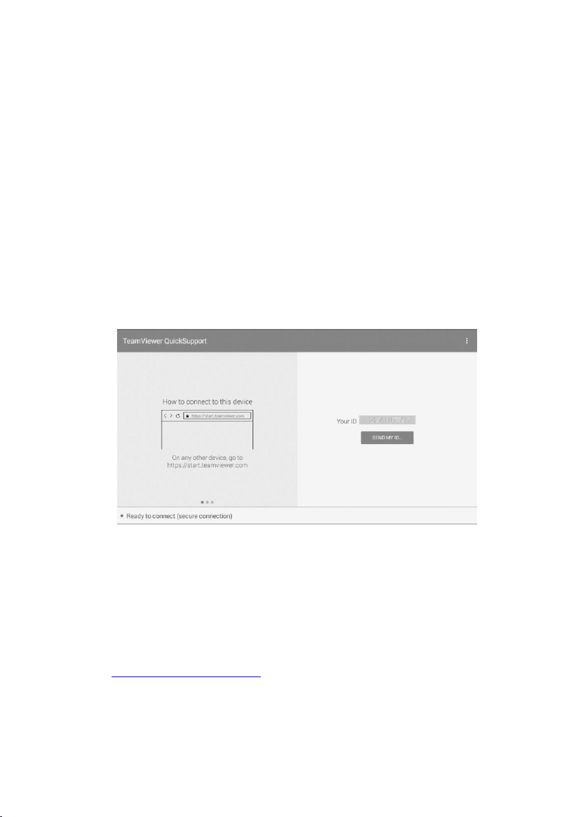
79
10. Remote Desk
The Remote Desk application launches the TeamViewer Quick Support program, which
is a simple, fast and secure remote control screen. You can use the application to receive
ad-hoc remote support from Autel’s support center, colleagues, or friends, by allowing
them to control your MaxiIM tablet on their PC via the TeamViewer software.
If you think of a TeamViewer connection as a phone call, the TeamViewer ID would be
the phone number under which all TeamViewer Clients can be reached separately. PCs
and mobile devices that run TeamViewer are identified by a globally unique ID. The first
time the Remote Desk application is started, this ID is generated automatically based on
the hardware characteristics and will not change.
Make sure the tablet is connected to the Internet before launching the Remote Desk
application, so that the tablet is able to receive remote support from the third party.
Figure 10-1 Sample Remote Desk Screen
To receive remote support from a partner
1. Power on the tablet.
2. Tap the Remote Desk application on the MaxiIM Job Menu. The TeamViewer
screen displays and the device ID is generated and shown.
3. Your partner must install the Remote Control software to his/her PC by
downloading the TeamViewer full version program online
(
http://www.teamviewer.com). Start the software on his/her PC at the same time,
in order to provide support and take control of the tablet remotely.
4. Provide your ID to the partner, and wait for him/her to send you a remote control
request.
5. A message displays to ask for your confirmation to allow remote control on your

80
device.
6. Tap Allow to accept, or tap Deny to reject.
Refer to the associated TeamViewer documents for additional information.
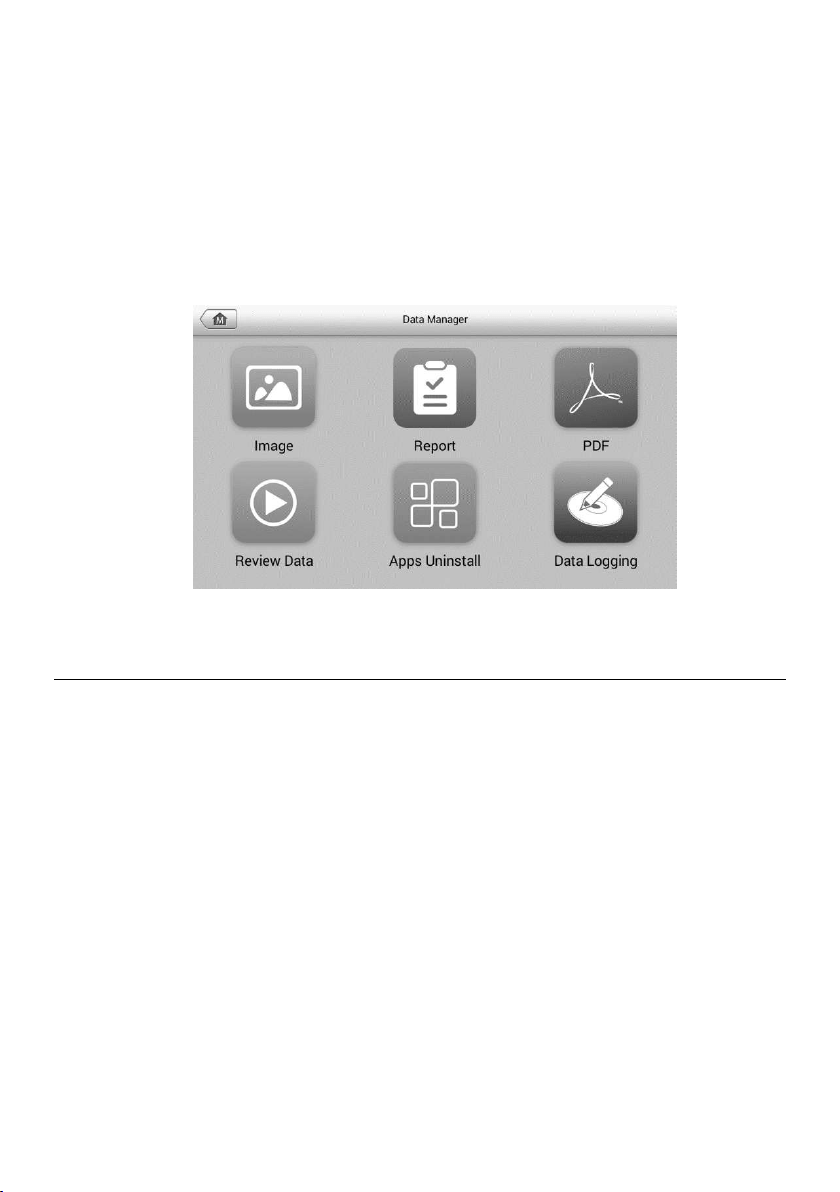
81
11. Data Manager
The Data Manager application is used to store, print, and review the saved files. Most
operations are controlled through the toolbar.
Selecting the Data Manager application opens the file system menu. Different file types
are sorted separately under different options, there are six types of information files to
be viewed or played back.
Operations
Data Manager Operations are based on toolbar controls. Details are explained in the
following sections.
Figure 11-1 Sample Data Manager Main Screen
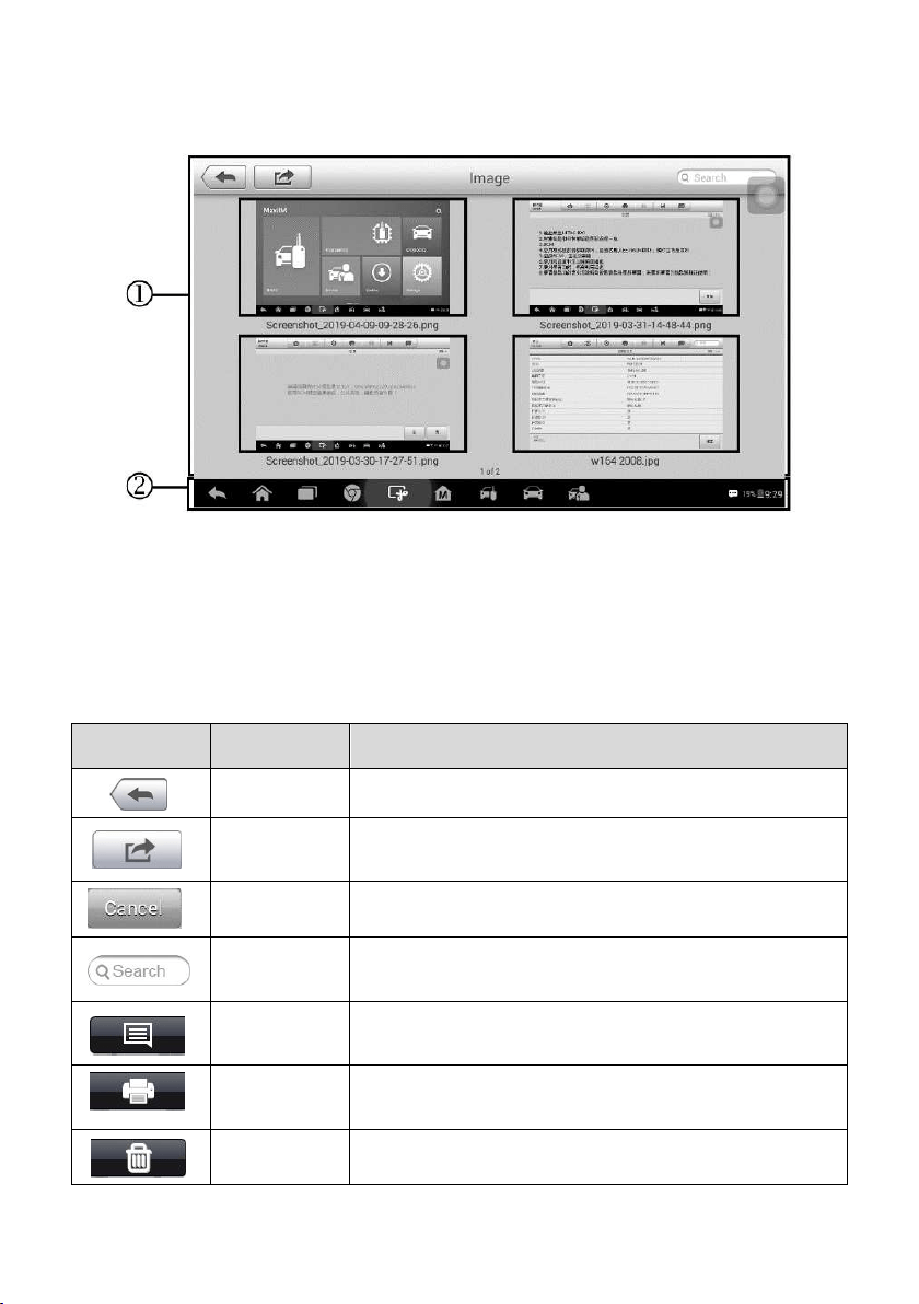
82
Image
The Image section contains all captured screenshot images.
1. Toolbar Buttons — used to edit, print and delete the image files. See the following
table for detailed information.
2. Main Section — displays the stored images.
Table 11-1 Toolbar Buttons in Image
Button
Name
Description
Back
Return to the previous screen.
Enter Edit
Tap to display the editing toolbar to print, delete or view
image information.
Cancel
Tap to close the editing toolbar or cancels file search.
Search
Quickly locates the image file by entering the vehicle
name, test path, file name or file info.
Info
Tap to open a window displaying the details of the
image.
Print
Tap to print the selected image. For details, see
Printing Setting.
Delete
Tap to delete the selected image.
Figure 11-2 Sample Image Screen
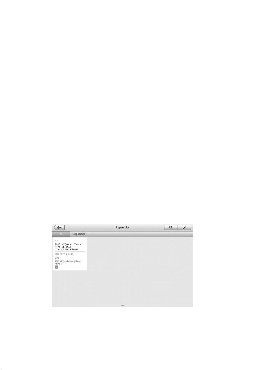
83
To edit image information
1. Tap the Data Manager application from the MaxiIM Job Menu.
2. Tap Image to access the image database.
3. Select an image to display it in full screen.
4. Tap the screen to display the editing toolbar.
5. Tap the Info button to open a window displaying the image information.
6. Tap the Edit button on the top right corner of the window. The editing screen
displays.
7. Edit the image information by entering the new file name, and file information.
8. Tap Done to save the information and exit, or tap Cancel to exit without saving.
To delete selected images
1. Tap the Data Manager application from the MaxiIM Job Menu.
2. Tap Image to access the JPG database.
3. Tap the image to display the editing toolbar.
4. Tap the Delete button, and then Delete image. The selected images will be
deleted.
Report
The Report section stores diagnostics information of the vehicle and forms a diagnostics
report for user to share.
To share a report
1. Tap the Data Manager application from the MaxiIM Job Menu.
Figure 11-3 Sample Report List Screen
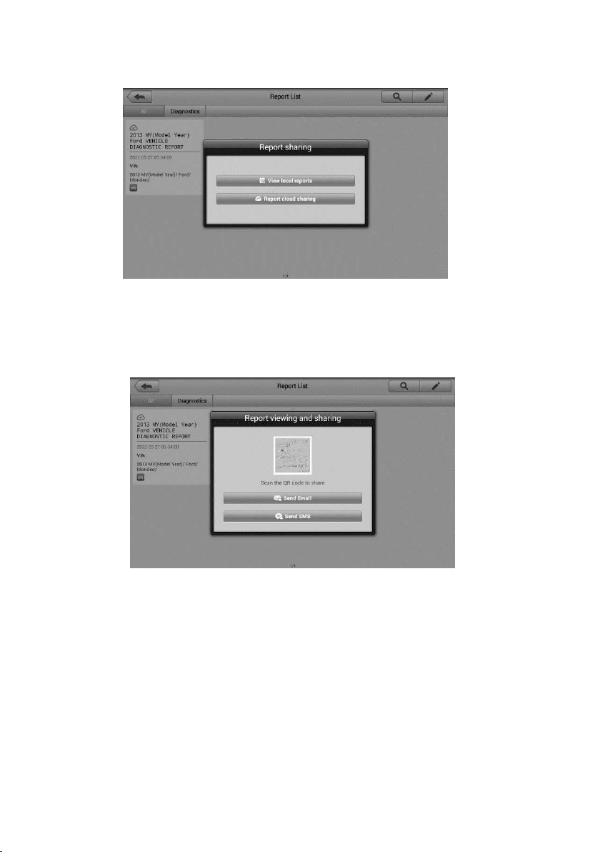
84
2. Tap Report to access the Report List screen.
3. Tap a report record to display the Report sharing dialog box.
4. Tap View local reports to display it in full screen.
5. Return to the Report List screen, tap the report and tap Report cloud sharing.
6. Scan the QR code or tap Send Email or Send SMS to share the report.
PDF
The PDF section stores and displays all PDF files of saved data. After entering the PDF
database, select a PDF file to view the stored information.
This section uses the standard Adobe Reader application for file viewing and editing.
Please refer to the associated Adobe Reader manual for more detailed instructions.
Review Data
The Review Data section allows you to playback the recorded data frames of live data
streams.
Figure 11-4 Sharing Report Screen 1
Figure 11-5 Sharing Report Screen 2
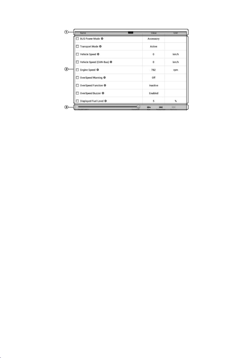
85
On the Review Data main screen, select a record file to playback.
1. Drop-down Toolbar — tap the button at the top center of the screen to open the
Drop-down Toolbar.
2. Main Section — displays the recorded data frames.
3. Navigation Toolbar — allows you to manipulate data playback.
Use the Navigation Toolbar buttons to playback the record data from frame to frame. Tap
Back to exit data playback.
Apps Uninstall
This section allows you to manage the firmware applications installed on the MaxiIM
Diagnostics System. Selecting this section opens a managing screen, on which you can
check all the available vehicle diagnostic applications.
Tap the vehicle firmware you want to delete, a blue tick at the upper right corner of the
firmware will display. Tap the Delete button on the top bar and tap OK to delete the
firmware from the system database.
Data Logging
The Data Logging section allows you to launch Support platform directly to view all
records of all sent or unsent (saved) data loggings on the diagnostic system.
Figure 11-6 Sample Data Playback Screen
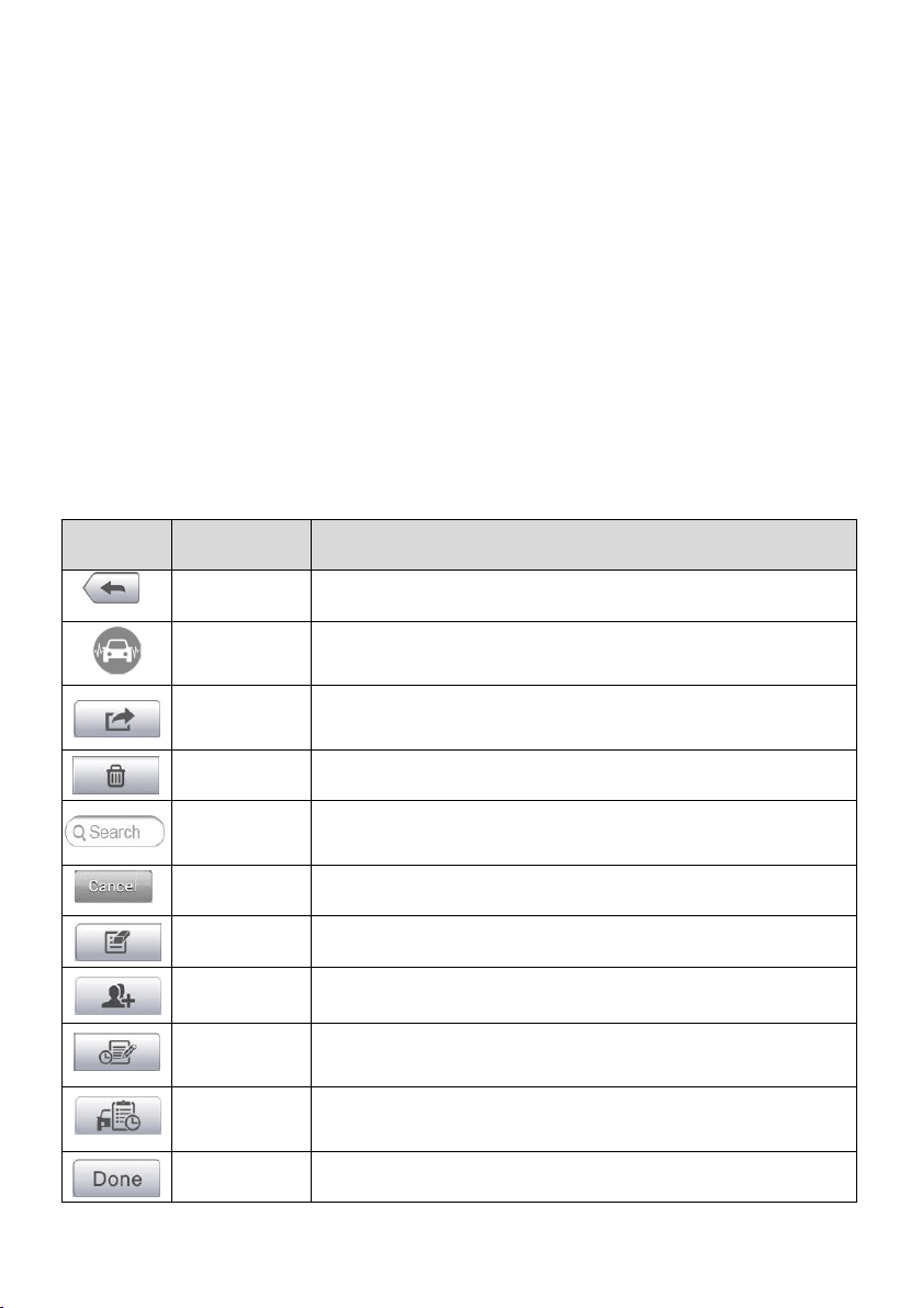
86
12. Shop Manager
The Shop Manager application helps you manage the workshop information, customer
information records, and keep test vehicle history records, which can help in dealing with
daily workshop business and improves customer service. There are three main functions
available:
Vehicle History
Workshop Information
Customer Manager
The operations of these functions are mainly manipulated by the toolbar buttons, which
are listed and described in the table below:
Table 12-1 Top Toolbar Buttons in Shop Manager
Button
Name
Description
Back
Return to the previous screen.
Diagnostics
Tap to display the Diagnostics screen to activate a direct test
session.
Enter Edit
Tap to display the editing toolbar to print or delete the
selected file.
Delete
Tap to delete the selected vehicle record item from the list.
Search
Quickly locates the vehicle record by entering the vehicle
name or test path.
Cancel
Tap to cancel edit or file search.
Edit
Tap to edit information for the displayed file.
Add
Account
Tap to create a new customer account file.
History
Notes
Tap to open a note form, which allows you to create audio
record, attach picture or video, or edit text notes.
Vehicle
History
Tap to open the Vehicle History screen which displays the
correlated test vehicle records.
Done
Complete editing and save the file.

87
Vehicle History
This function stores records of test vehicle history, including vehicle information and the
retrieved DTCs from previous diagnostic sessions. Test information is summarized and
displayed in an easy-to-view table listing. The Vehicle History also provides direct access
to the previously tested vehicle and allows you to restart a diagnostic session without the
need to do vehicle identification again.
1. Top Toolbar Buttons — navigation and application controls.
2. Main Section — displays all the vehicle history records.
To activate a test session for the recorded vehicle
1. Tap the Shop Manager application on the MaxiIM Job Menu.
2. Tap Vehicle History
3. Tap the Diagnostics button at the bottom of the thumbnail of a vehicle record
item. Or,
4. Select a vehicle record item by tapping the thumbnail.
5. A Historical Test record sheet displays, check the recorded information of the
recorded test vehicle, and tap the Diagnostics button on the upper right corner.
6. The vehicle’s Diagnostics screen displays and a new diagnostic session is
activated, see
Diagnosis for detailed instructions on vehicle diagnostic
operations.
Figure 12-1 Sample Vehicle History Screen
—①
—②
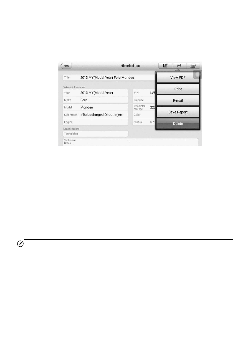
88
Historical Test Record
The Historical Test record of the tested vehicle is a detailed data form, which includes all
general information of the vehicle such as vehicle year, make and model and the
diagnostic trouble codes retrieved from the previous test sessions, as well as other
service details that can be added manually by the technician himself.
To edit the Historical Test record
1. Tap the Shop Manager application on the MaxiIM Job Menu.
2. Tap Vehicle History.
3. Select the specific vehicle history record thumbnail from the main section. The
Historical Test record will display.
4. Tap the Edit button to start editing.
5. Tap on each item to input the corresponding information or attach files or images.
NOTE
The vehicle VIN number, license number or customer account information are correlated
by default. Adding one of these IDs will automatically be associated with the other ID on
the test record.
6. Tap Add to Customer to correlate the Historical Test record sheet to an existing
customer account, or add a new associated account to be correlated with the
test vehicle record. See Customer Manager for more information.
7. Tap Done to save the updated record, or tap Cancel to exit without saving.
Figure 12-2 Sample Historical Test Record Sheet
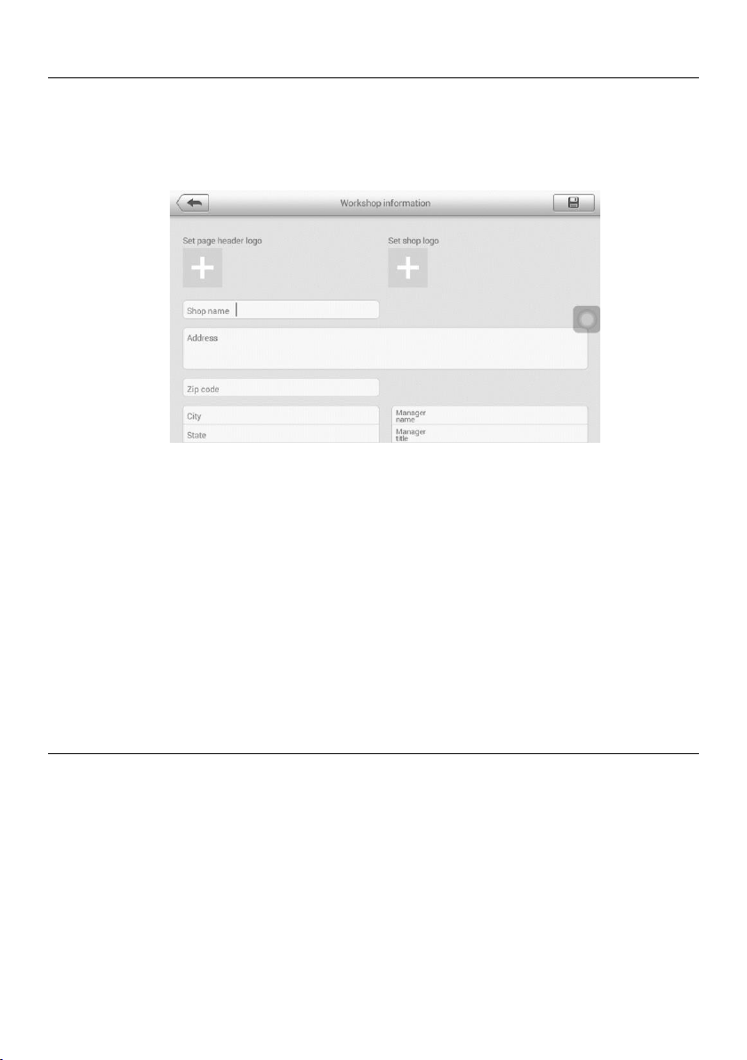
89
Workshop Information
The Workshop Information form allows you to input, edit, and save the detailed workshop
information, such as shop name, address, phone number and other remarks, which,
when printing vehicle diagnostic reports and other associated test file, will display as the
header of the printed documents.
To edit the Workshop Information sheet
1. Tap the Shop Manager application on the MaxiIM Job Menu.
2. Tap Workshop Information.
3. Tap the Edit button on the top toolbar.
4. Tap on each field to input the appropriate information.
5. Tap Done to save the updated workshop information record, or tap Cancel to
exit without saving.
Customer Manager
The Customer Manager function allows you to create and edit customer accounts. It
helps you to save and organize all customer information accounts that are correlated with
the associated test vehicle history records.
To create a customer account
1. Tap the Shop Manager application on the MaxiIM Job Menu.
2. Tap Customer Manager.
3. Tap the Add Account button. An empty information form displays, tap each field
to input the appropriate information.
Figure 12-3 Sample Workshop Information Sheet

90
NOTE
The items that must be filled are indicated as required fields.
4. Tap the cross mark beside the Name chart to add a photo. A sub menu displays,
select Take Photo to take a new photo for the account, or select Choose Photo
to choose from the existing files.
5. Some customers may have more than one vehicle for service; you can always
add new vehicle information to the account. Tap Add New Vehicle Information,
and then fill in the vehicle information. Tap the button to cancel.
6. Tap Done to save the account, or tap Cancel to exit without saving.
To edit a customer account
1. Tap the Shop Manager application on the MaxiIM Job Menu.
2. Tap Customer Manager.
3. Select a customer account by tapping the corresponding name card. A
Customer Information record displays.
4. Tap the Edit button on the top toolbar to start editing.
5. Tap on the input field to edit or amend information, and enter updated
information.
6. Tap Done to save the updated information, or tap Cancel to exit without saving.
To delete a customer account
1. Tap the Shop Manager application on the MaxiIM Job Menu.
2. Tap Customer Manager.
3. Select a customer account by tapping the corresponding name card. A
Customer Information record displays.
4. Tap the Edit button on the top toolbar to start editing.
5. Tap the Delete Customer Information button. A confirmation message
displays.
6. Tap OK to confirm the command, and the account is deleted. Tap Cancel to
cancel the request.
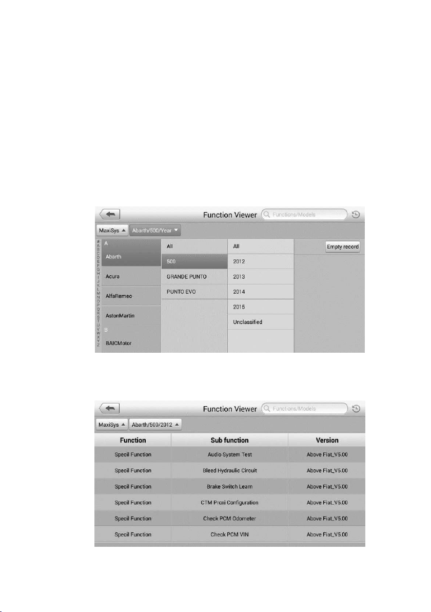
91
13. Function Viewer
The Function Viewer allows you to search the supported functions. There are two ways of
searching, by vehicle or by function.
To search by the vehicle
1. Tap the Function Viewer application on the MaxiIM Job Menu. The Function
Viewer application screen displays.
2. Tap the tool name on the top left to drop down the tool list, tap the one you want
to search.
3. Tap the vehicle brand, model, and year you want to search.
Figure 13-1 Sample Function Viewer Screen 1
4. All the functions supported by the selected tool for the selected vehicle displays
with three column: function, sub function, and version.
Figure 13-2 Sample Function Viewer Screen 2

92
To search by the functions
1. Tap the Function Viewer application on the MaxiIM Job Menu. The Function
Viewer application screen displays.
2. Tap the tool name on the top left to drop down the tool list, tap the one you want
to search.
3. Type in the function you want to search to the top right search column. All the
vehicles with this function will be listed with 8 columns, the Brand, Model, Year,
System, Sub system, Function, Sub function, and Version.
NOTE
Fuzzy search is supported, type in part of the function you want to search for.

93
14. Support
This application launches the Support platform which synchronizes Autel’s on-line service
base station with the tablet. In order to synchronize the device to your on-line account, you
need to register the product through the Internet when you use it for the first time. The
Support application is connected to Autel’s service channel and on-line communities which
provides the quickest way for problem solutions, allowing you to submit complaints or sent
help requests to obtain direct services and supports.
Product Registration
In order to get access to the Support platform and obtain update and other services from
Autel, you are required to register the MaxiIM Diagnostics Device the first time you use it.
To register the diagnostics device
1. Visit
http://pro.autel.com.
2. If you already have an Autel account, sign in with your account ID and
password, and skip to step 9.
3. If you are a new member to Autel, click Register on the left side of the screen
to create your Autel ID.
4. Enter your personal information. Fields marked with an asterisk (*) are
mandatory.
5. Enter your email address, then click Request. You will receive an email from
Autel with your verification code. Open the email and copy the code into the
proper input box.
6. Set a password for your account, and enter the password again to confirm.
7. Read the Autel User Service Agreement and Autel Privacy Policy, then
check the box to accept the terms.
8. After all the information is entered, click Register. Once your account is
successfully registered, you will be redirected to the Product Registration
screen. If not, click the button on the screen.
9. Your product serial number and password are required to complete your
registration. To find your serial number and password on the tablet: go to
Settings > About.
10. Enter your tablet serial number and password. Enter the CAPTCHA code as
shown. And click Submit to complete your product registration.
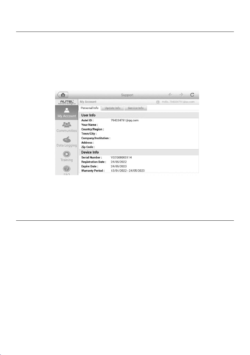
94
Support Screen Layout
The Support application screen is navigated with four simple buttons on the top navigation
bar, operation of each is described below in turn from left to right:
Home Button — returns to the MaxiIM Job Menu.
Back — press to return to the previous screen.
Forward — press to advance one screen at a time until the last screen visited is
displayed.
Refresh — reload and update the screen.
Figure 14-1 Sample Support Application Screen
The main section of the Support screen is divided into two sections. The narrow column
on the left is the main menu; select a heading from the main menu to its corresponding
functions on the right.
My Account
The My Account screen displays the comprehensive information of the user and the
product including the user, device, update and service information, synchronized with the
registered account.
Personal Info
The User Info and Device Info are both included under the Personal Info section.
User Info — displays detailed information of your registered on-line Autel account,
such as your Autel ID, Name, Address and other contact information.
Device Info — displays the registered product information, including the Serial Number,
Registration Date, Expire Date, and Warranty Period.
Update Info
The Update Info section displays a detailed record of the product’s software update history,
including the product serial number, software version or name, and the update time.
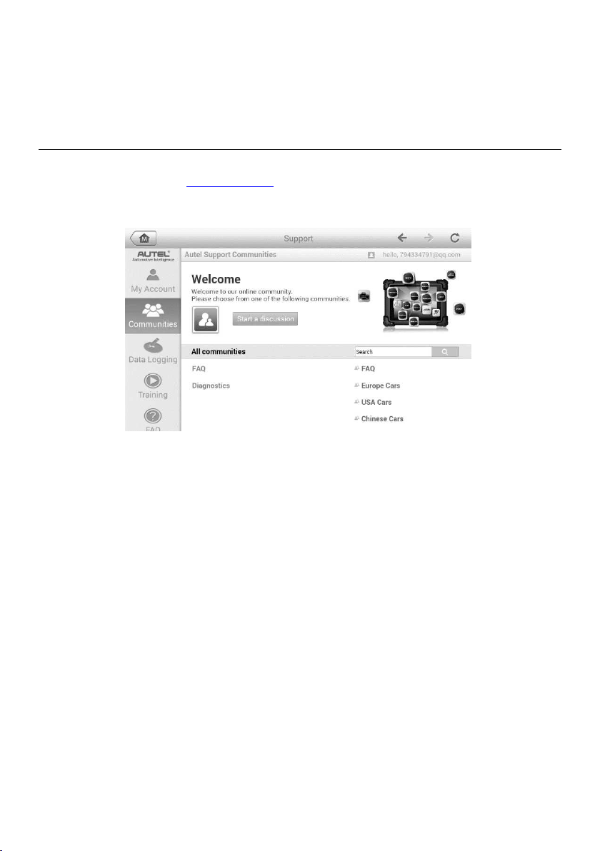
95
Service Info
The Service Info section displays a detailed record of the device’s service history
information. The device’s service history including completed service repairs and software
re-installations will be recorded and synchronized with the associated account.
Communities
The Communities section launches and synchronizes with the Technical Forums on
Autel’s official website
www.autel.com. The community’s forum allows for discussion of
technical issues, the sharing of information or tips with other members in Autel’s online
support communities.
Figure 14-2 Sample Communities Home Screen
To start a discussion
1. Tap Start a discussion on the Communities Home screen. A list of the major
forums is displayed.
2. Select a desired community according to the subject you are interested in.
3. Enter your topic and the discussion content in the appropriate input field.
4. Select a category or edit tags for the discussed post. This will help other
members with similar interest to find your post.
5. Tap OK to submit the post.
To join and reply to a discussion post
1. Select a forum group either by product or feature on the Communities Home
screen. A list of the latest posts is displayed.
2. Select a specific category on the Categories menu to better pinpoint the topics
you are most interested in.
3. Tap the
○
> button on the right side of the topic item to view the discussion. The
posts displays.
4. Browse through all the posts by sliding the screen up and down. Tap Go to

96
original post to return to the first post.
5. Tap Reply to reply to a specific post, or tap Reply to original post to join and
continue the whole discussion.
6. Enter your comment in the input field, and tap OK to submit your post.
Data Logging
The Data Logging section keeps records of all sent or unsent (saved) data loggings on the
diagnostics system. The support personnel receive and process the submitted reports
through the Support platform. Support personnel will reply to the submitted issue and
corresponding Data Log session within 48 hours.
To make a reply in a Data Logging session
1. Tap on the Sent tag to view a list of submitted data logs.
2. Select a specific item to view the latest update of the submitted issue.
3. Tap on the input field at the bottom of the screen and enter text. Tap the Audio
button to record a voice message, or tap camera button to take a picture.
4. Tap Send to send your message to the technical center.
User Profile
The User Profile section allows you to set personal Avatar, check your member status and
review your posts to the communities.
Tap the Avatar image on the Communities screen to open the User Profile.
Profile — displays the user’s personal information and member status. The Related
links allow you to check the Top Users (ranked according to their points and levels) in the
communities, as well as to find out about other online users.
Avatar — allows you to select an image to set as an Avatar to be displayed in the
communities.
Stuff — displays a list of your posts in the various forums.
Training
The Training section provides quick links to Autel’s online video accounts. Select a video
channel by language to see all the available online tutorial videos.
FAQ
The FAQ section provides comprehensive answers to the most frequently asked questions
about member accounts and online subscription purchases.
Account — displays questions and answers about the use of Autel’s online user
account.
Shopping & Payment — displays questions and answers about online subscription
purchase, payment methods or procedures.

97
15. Academy
Autel provides various tutorials and technical bulletins written by top-notch technicians and
product experts. Please review the materials on the tablet or view additional technical
articles on the online forum by clicking on click on the links provided.
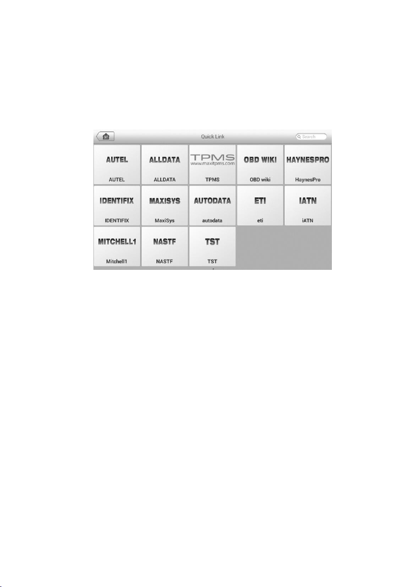
98
16. Quick Link
The Quick Link application provides access to Autel’s official website and to other
popular automotive service websites. These sites are invaluable resources of
automotive information and repair data and include forums, video training and expert
consultation.
Figure 16-1 Sample Quick Link Screen
To open a quick link
1. Tap the Quick Link application on the MaxiIM Job Menu. The Quick Link
application screen displays.
2. Select a website thumbnail from the main section. The Chrome browser is
launched and the selected website is opened.
3. Now you can start exploring the website.

99
17. Maintenance and Service
Maintenance Instructions
The following shows how to maintain your devices, together with precautions to take.
Use a soft cloth and alcohol or a mild window cleaner to clean the touch screen of
the tablet.
Do not use any abrasive cleansers, detergent, or automotive chemicals to the tablet.
Maintain the devices in dry conditions and keep them within normal operating
temperatures.
Dry your hands before using the tablet. The touch screen of the tablet may not work
if the touch screen is moist, or if you tap the touch screen with wet hands.
Do not store the devices in humid, dusty or dirty areas.
Check the housing, wiring, and connectors for dirt and damage before and after each
use.
At the end of each work day, wipe the device housing, wiring, and connectors clean
with a damp cloth.
Do not attempt to disassemble your tablet or the VCI unit.
Do not drop or cause severe impact to the devices.
Use only authorized battery chargers and accessories. Any malfunction or damage
caused by the use of unauthorized battery charger and accessories will void the
limited product warranty.
Ensure that the battery charger does not come in contact with conductive objects.
Do not use the tablet beside microwave ovens, cordless phones and some medical
or scientific instruments to prevent signal interference.

100
Troubleshooting Checklist
A. When the tablet does not work properly:
Make sure the tablet has been registered online.
Make sure the system software and diagnostic application software are properly
updated.
Make sure the tablet is connected to the Internet.
Check all cables, connections, and indicators to see if the signal is being
received.
B. When battery life is shorter than usual:
This may happen when you are in an area with low signal strength. Turn off your
device if is not in use.
C. When you cannot turn on the tablet:
Make sure the tablet is connected to a power source or the battery is charged.
D. When you are unable to charge the tablet:
Your charger maybe out of order. Contact your nearest dealer.
You may be attempting to use the device in an overly hot/cold temperature.
Charge the device in a cooler or warmer area.
Your device may have not been connected to the charger properly. Check the
connector.
NOTE
If the problems persist, please contact Autel’s technical support personnel or your local
selling agent.

101
About Battery Usage
Your tablet is powered by a built-in Lithium-ion Polymer battery. This means that, unlike
other forms of battery technology, you can recharge your battery while some charge
remains without reducing your tablet’s autonomy due to the “battery memory effect”
inherent in those technologies.
DANGER
The built-in Lithium-ion Polymer battery is factory replaceable only; incorrect
replacement or tampering with the battery pack may cause an explosion.
Do not use a damaged battery charger.
Do not disassemble or open crush, bend or deform, puncture or shred.
Do not modify or remanufacture, attempt to insert foreign objects into the battery,
expose to fire, explosion or another hazard.
Use only the included charger and USB cables. Failure to use Autel-authorized
charger and/or USB cables, may result in device malfunction or failure.
Use of an unqualified battery or charger may present a risk of fire, explosion,
leakage, or another hazard.
Avoid dropping the tablet. If the tablet is dropped, especially on a hard surface, and
the user suspects damage, take it to a service center for inspection.
The closer you are to your network’s wireless router, the longer your tablet usage
time because less battery power is consumed for the connection.
The battery recharging time varies depending on the remaining battery capacity.
Battery life inevitably shortens over time.
Since overcharging may shorten battery life, remove the tablet from its charger once
it is fully charged. Unplug the charger, once charging is complete.
Leaving the tablet in hot or cold places, especially inside a car in summer or winter,
may reduce the capacity and life of the battery. Always keep the battery within
normal temperatures.

102
18. Compliance Information
FCC Compliance
FCC ID: WQ8-1610MX808
This device complies with Part 15 of the FCC rules and Industry Canada’s license-
exempt RSSs. Operation is subject to the following two conditions:
1. This device may not cause harmful interference.
2. This device must accept any interference received, including interference that may
cause undesired operation.
Cet appareil est conforme aux CNR exempts de licence d’Industrie Canada. Son
fonctionnement est soumis aux deux conditions suivantes:
1. Ce dispositif ne peut causer des interferences; et
2. Ce dispositif doit accepter toute interférence, y compris les interférences qui peuvent
causer un mauvais fonctionnement de l’appareil.
WARNING
Changes or modifications not expressly approved by the party responsible for
compliance could void the user’s authority to operate the equipment.
NOTE
This equipment has been tested and found to comply with the limits for a Class B digital
device, pursuant to Part 15 of the FCC Rules. These limits are designed to provide
reasonable protection against harmful interference in a residential installation.
This equipment generates uses and can radiate radio frequency energy and, if not
installed and used in accordance with the instructions, may cause harmful interference
to radio communications. However, there is no guarantee that interference will not occur
in a particular installation. If this equipment does cause harmful interference to radio or
television reception, which can be determined by turning the equipment off and on, the
user is encouraged to try to correct the interference by one or more of the following
measures:
-- Reorient or relocate the receiving antenna.
-- Increase the separation between the equipment and receiver.
-- Connect the equipment into an outlet on a circuit different from that to which the
receiver is connected.
-- Consult the dealer or an experienced radio/TV technician for help.

103
Changes or modifications not expressly approved by the party responsible for compliance
could void the user’s authority to operate the equipment.
SAR
The radiated output power of this device is below the FCC radio frequency exposure limits.
Nevertheless, the device should be used in such a manner that the potential for human
contact is minimized during normal operation.
The exposure standard for wireless devices employs a unit of measurement known as the
Specific Absorption Rate, or SAR. The SAR limit set by the FCC is 1.6 W/Kg. Tests for
SAR are conducted using standard operating positions accepted by the FCC with the
device transmitting at its highest certified power level in all tested frequency bands.
Although the SAR is determined at the highest certified power level, the actual SAR level
of the device while operating can be well below the maximum value. This is because the
device is designed to operate at multiple power levels so as to use only the power required
to reach the network. To avoid the possibility of exceeding the FCC radio frequency
exposure limits, human proximity to antenna should be minimized.
RF WARNING STATEMENT
The device has been evaluated to meet general RF exposure requirement. The device
can be used in portable exposure condition without restriction.
The term “IC” before the radio certification number only signifies that IC technical
specifications were met.
RoHS COMPLIANCE
This device is declared to be in compliance with the European RoHS Directive
2011/65/EU.
CE COMPLIANCE
This product is declared to conform to the essential requirements of the following
Directives and carries the CE mark accordingly:
EMC Directive 2014/30/EU
R&TTE Directive 1999/5/EC
Low Voltage Directive 2014/35/EU

104
19. Warranty
Limited One Year Warranty
Autel Intelligent Technology Corp., Ltd. (the Company) warrants to the original retail
purchaser of this MaxiIM Diagnostic Device, that should this product or any part thereof
during normal consumer usage and conditions, be proven defective in material or
workmanship that results in product failure within one (1) year period from the date of
purchase, such defect(s) will be repaired, or replaced (with new or rebuilt parts) with
Proof of Purchase, at the Company’s option, without charge for parts or labor directly
related to the defect(s).
The Company shall not be liable for any incidental or consequential damages arising
from the use, misuse, or mounting of the device. Some states do not allow limitation on
how long an implied warranty lasts, so the above limitations may not apply to you.
This warranty does not apply to:
a) Products subjected to abnormal use or conditions, accident, mishandling, neglect,
unauthorized alteration, misuse, improper installation or repair or improper storage;
b) Products whose mechanical serial number or electronic serial number has been
removed, altered or defaced;
c) Damage from exposure to excessive temperatures or extreme environmental
conditions;
d) Damage resulting from connection to, or use of any accessory or other product not
approved or authorized by the Company;
e) Defects in appearance, cosmetic, decorative or structural items such as framing and
non-operative parts.
f) Products damaged from external causes such as fire, dirt, sand, battery leakage,
blown fuse, theft or improper usage of any electrical source.
IMPORTANT
All contents of the product may be deleted during the process of repair. You should create
a back-up copy of any contents of your product before any repair services.