Loading ...
Loading ...
Loading ...
10
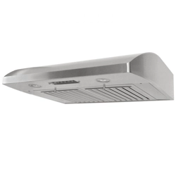
4. For Rear 3-1/4” x 10” vent installation only:
-
Remove attached 6” exhaust and discard.
(Figure 10) Keep 13 screws to install vent
covers.
-
Remove duct knockout from back of the
hood and discard. (Figure 12) Unscrew 3-
1/4” x 10” Vent Cover from rear exhaust
(located inside hood); keep screws to install
3-1/4” x 10” Exhaust.
-
Align Top Vent Cover {P} and 3-1/4” x 10”
Vent Cover (removed from rear exhaust)
using 14 screws (13 screws taken from 6”
exhaust). (Figure 12) Follow instructions in
Step 5 to attach Hood Mounting Bracket {M}
and two Duct Cover Support {K} using 14
screws (13 screws taken from 6” exhaust).
(Figure 14)
-
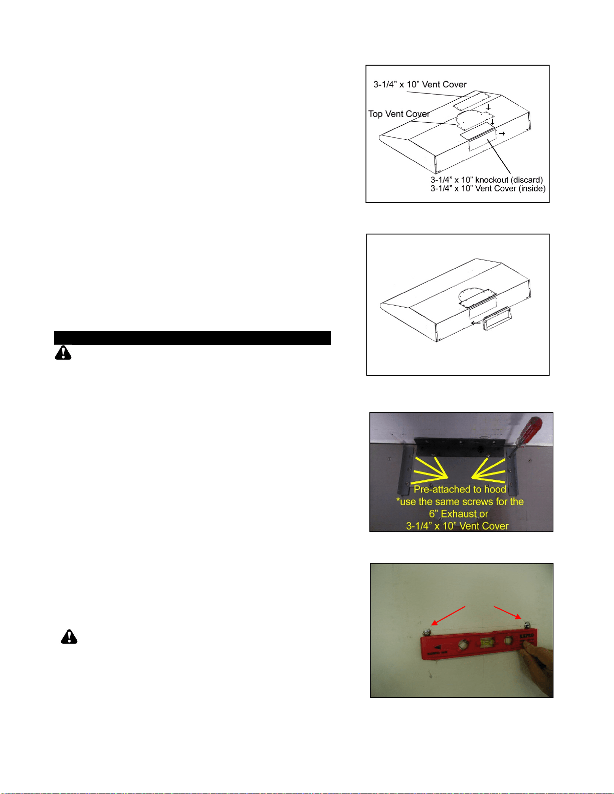
Attach the 3-1/4” x 10” Exhaust {O} to rear
exhaust (located inside hood) using 10
screws taken from rear vent cover. (Figure
13)
Hood Installation
CAUTION
: If moving the cooking range is
necessary to install the hood, turn off the power
in an electric range at the main electrical box.
SHUT OFF THE GAS BEFORE MOVING A GAS
RANGE. And use a protective covering to
protect cooktop and/or countertop from
damage.
5. Secure Hood-Mounting Bracket {M} and two
Duct Cover Support {K} on top of the hood with
eight pre-attached screws. Use four 3/16” x 3/8”
screws {J} for Hood-Mounting Bracket {M}.
(Figure 14)
6. Using references on Table 2 and
measurements on page 16-17, mark the
leveling point of the hood. Position two
mounting screws (provided) on the wall, leaving
1/8” away from the wall as shown in Figure 15.
7. Align Hood-Mounting Bracket {M} to the two
screws on the wall and hook hood into place.
Tighten screws to secure hood to the wall.
CAUTION
: MAKE SURE HOOD IS
SECURE BEFORE RELEASING
Figure 12
Figure 13
Figure 14
Figure 15
Mounting Screws
Loading ...
Loading ...
Loading ...