

2
ENGLISH
TABLE OF CONTENTS
SAFETY PRECAUTION ...............3
- Precautions for the AC Adapter and Power .. 4
- Precautions for Moving the Product ................ 6
- Precautions for Installing the Product ............. 7
- Precautions for Cleaning the Product ............. 9
- Precautions for Using the Product .................10
- Precautions for Using the Remote control 12
- Precautions for Experiencing Image
Retention ......................................................................12
- Product Disposal ......................................................12
ASSEMBLING AND PREPARING
................................................. 13
- Optional Accessories ..............................................14
- Product Installation.................................................15
- Installing on a Wall ..................................................16
- Parts and Buttons ................................................... 18
REMOTE CONTROL ................. 20
GETTING READY ..................... 22
MAKING CONNECTIONS ........ 22
- Connecting to a PC .................................................22
- SDI Signal Connection ...........................................23
- External Device Connection ............................... 23
- Using the Input List.................................................24
MENU ....................................... 25
USER SETTINGS ...................... 33
- Picture ............................................................................ 34
- Marker ............................................................................ 41
- Audio ...............................................................................44
- GPI ....................................................................................47
- Video Analysis ............................................................49
- Advanced Settings ..................................................52
- Calibration ....................................................................61
TROUBLESHOOTING ............... 63
PRODUCT SPECIFICATIONS ... 66
LICENSES ................................. 73
3
ENGLISH
WARNING - This equipment is compliant with Class A of CISPR 32. In a residential environment this equipment may
cause radio interference.
SAFETY PRECAUTION
The safety precautions are intended to prevent unexpected danger or harm by helping the user to use the product
safely and for its intended purpose.
WARNING
If you ignore the warning message, you may be seriously injured or there is a possibility of accident or death.
CAUTION
If you ignore the caution message, you may be slightly injured or the product may be damaged.
WARNING
This product cannot be installed outdoors. Only use the product indoors as installed by the installer.

4
ENGLISH
Precautions for the AC Adapter and Power
WARNING
•
Use only the power cord or AC adapter provided or approved by LG Electronics, Inc. If you use another power cord,
make sure that it is certified by the national standards. If the power cable is faulty in any way, please contact the
manufacturer or the nearest authorised service center for a replacement.
• Operate the display only from a power source (i.e. voltage) indicated in the product specification.
- Otherwise the product can be damaged, fire can occur or you may be electrocuted. If you are not sure what type of
power supply you have, consult a certified installation company.
• Make sure the power cord connect to a properly grounded outlet.
- If you do not you may be electrocuted or injured or the product can be damaged.
• Insert the power plug or AC adapter firmly so it cannot come loose.
- Poor connection may cause a fire or electric shock.
• In the presence of thunder and lightning, never touch the power cord and signal cable because it can be very
dangerous.
- It can cause electric shock.
• Be careful not to step or place heavy objects (electronic appliances, clothing, etc.) on the power cord or AC adapter.
Additionally, do not bend or pull out the power cord or AC adapter with excessive force.
- Damaged power cords may cause a fire or electric shock.
• Do not connect power cord or AC adapter damaged with sharp objects to power outlet.
- You may be electrocuted.
• Do not insert a conductor (like a metal chopstick) into one end of the power cord while the other end is connected to
the input terminal on the wall. Additionally, do not touch the power cord right after unplugged.
- You may be electrocuted.
• Do not use with a multi-outlet connected by many electrical product and heating devices. Use an exclusive multi-
outlet with a grounding terminal.
- A fire can break out due to overheating.

5
ENGLISH
• If water or any foreign substance goes inside the product, disconnect the power cord immediately and contact the
service center.
- Otherwise, this may cause a fire or electric shock due to damage to the product.
• Keep the power cord or AC adapter away from any heating devices.
- The cord coating may melt and cause fire or electric shock.
• Never disassemble, repair or modify the power cord or AC adapter.
- This may cause a fire or electric shock.
• Please make sure the main power cutoff device is power plug and the product is installed near the wall outlet that is
easily accessible.
• As long as this unit is connected to the AC wall outlet, it is not disconnected from the AC power source even if the
unit is turned off.
• Power consumption will be ‘0’ only when the power plug is unplugged.
• Use an power plug as a disconnect device.
CAUTION
•
If the outlet, pins of the power plug, or AC adapter is covered with dust, be sure wipe and keep clean.
- Overheating due to layers of dust may cause a fire or electric shock.
• If the outlet, pins of the power plug, or AC adapter is covered with water, be sure wipe and keep clean. Additionally,
Do not touch the power plug or AC adapter with wet hands.
- This may cause an electric shock.
• Do not turn the product on or off by plugging in or unplugging the power plug from the power outlet. It means do not
use the power plug as a switch.
- This may cause an electric shock or product malfunction.
• Do not unplug the power cord while the product is in use.
- Electrical shock can damage the product.

6
ENGLISH
Precautions for Moving the Product
WARNING
•
Contact the service center before moving the product.
- It may cause electric shock and damage the product.
• Make sure the product is turned off, unplugged, and all cables have been removed before the product is moved.
- You may be electrocuted or the product can be damaged.
• When moving the product, Do not shock the product and impact on the front panel of the product.
- You may be electrocuted or the product can be damaged.
• Complywiththenumberofpeopleaccordingtoweightofproduct.(Under25Kg(55.1lbs)perpersonuselifting
equipmentwhenexceeding100Kg(220.4lbs))
- If use the damaged product again, contact the service center because it can cause electric shock or fire.
• Do not hold it upside down while holding only the stand. (It is for stand supported models only.)
- This may cause stand warping, panel damage and other types of product damage.
CAUTION
•
Do not dispose the product-packing box. It may be used put the product in the box when carrying it.

7
ENGLISH
Precautions for Installing the Product
WARNING
•
Contact the service center before installing the product.
- It can cause electric shock and damage the product.
• Do not drop an object on or impact on the product. Keep out of reach of children and do not place toys or objects
near the product to prevent throwing things on the product screen.
- It can cause injury to human, problem to product and damage the display.
• Do not put heavy objects on, or hang from, the product.
- If the product collapses or is dropped, you may be injured.
• Do not touch the surface of product to overheat.
- It can cause injury to human.
• Install the product firmly fixed on a wall, etc. to prepare against external impact such as wind and earthquake.
- You must refer to the manual provided.
• Do not Install the product on a floor to prevent Children from climbing or hanging on the product.
- If the product collapses or is dropped, you may be injured.
• Do not install it where there are heating devices such as electrical heaters or lighting equipment.
- Fire, electrical shock, malfunction may occur.
• Do not install this product by yourself as you may injure yourself or cause damage to product. Please contact service
engineer authorised by service center.
• Do not install this product on a wall if it could be exposed to oil or oil mist.
- This may damage the product and cause it to fall.
• Do not leave the power or signal cable, etc. on the pathway.
- This could cause a trip or fall, which can be caused electrical shock, fire, product breakdown, or injury.
• Do not let the product drop when connecting it to an external device connected with a short cable.
- This may cause injury and damage to the product.
• If you drop the product or the case is broken, turn off the product and unplug the power cord and contact the service
center.
- If you continue to use without taking proper measures, electrical shock or fire can occur.
• Install the product in a dry place where it is not near dust and water. Avoid high temperatures and humidity.
- This may cause electrical shock, fire or product damage.
• Safely install the product in a place that can hold the weight of the product.
- A lack of strength may cause the product to fall.
• Take a comfortable and natural position to relax the muscles when working with a product.

8
ENGLISH
CAUTION
•
Install the product where no Electromagnetic Interference occurs.
• If you install the product in a place that does not meet the recommended conditions, this may cause serious damage
to the product’s picture quality, life cycle, and appearance. Please check with service engineer before installing. Please
do not install the product in places such as where there is an abundance of fine dust or oil mist, chemical substances
are used, exposed to direct sunlight, the temperature is very high or low, the humidity is very high.
• Make sure the product is well ventilated by Installing at a distance (100 mm (3.9 inches) or more) from the wall.
- If you install the product too close to the wall, it may be deformed or fire can break out due to internal heat buildup.
• Do not cover the product with tablecloth or curtain or other material (e.g. plastic) while plugged in to block the
ventilation hole of the product.
- The product can be deformed or fire can break out due to overheating inside the product.
• Do not install the product in an area with poor ventilation (e.g. on a bookshelf, in a closet) or outside and avoid placing
on cushions or carpets.
- The product could catch fire due to overheating inside the product.
• Install the product on a flat and stable place that is large enough to support the product.
- If the product is dropped, you may be injured or the product may be broken.
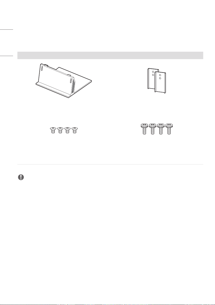
• When installing the product on a shelf or cabinet, make sure that the bottom end of the product is not protruding
forward.
- The product may fall due to unbalanced center of gravity, which may cause personal injury or damage to the
product. Be sure to use cabinets or shelves that fit your product.

9
ENGLISH
Precautions for Cleaning the Product
WARNING
•
Keep the product clean at all times.
- If you don’t clean the unit for a long time and it becomes covered in dust, it can cause fire or product damage.
• When you need to clean the inside of the product, you must contact the service center.
- Otherwise, cleaning without support may cause a fire, electric shock, or damage to the product.
• When cleaning the product, unplug the power cord and wipe gently with a soft cloth to prevent scratching.
- An electric shock may occur or damage to the screen as get a scratch.
• Whenyouwanttocleanthefrontframe,spraywaterontoasoftcloth2to4timesandwipeinonedirectiononly.
- Too much moisture may cause staining.
CAUTION
•
When cleaning the product or the screen, unplug the power cord and wipe it gently with a soft cloth. Do not spray
water or other liquids directly on the product. Especially, do not clean your product with chemicals including glass
cleaner, any type of air freshener, insecticide, lubricants, wax (car, industrial), abrasive, thinner, benzene, alcohol, etc.,
which can damage the product or its panel.
- This may result in fire, electric shock or product damage (deformation, corrosion or breakage).

10
ENGLISH
Precautions for Using the Product
WARNING
•
Do not use the product in any environment with excessively high temperatures or humidity.
- It may cause electrical shock or damage the product.
• If you use the product for a long period of time, take a rest from time to time to protect your vision.
- Extended viewing could result in impaired vision.
• Listening at high volume or using for a long time can cause damage to your hearing.
• In the event that liquid or a foreign object falls into the product, please switch it off and unplug it from the wall outlet
and contact the service center.
- Otherwise, the product may cause fire or electric shock.
• In the event that no image appears on the screen or no sound is heard, stop using the product. Switch it off
immediately, unplug it from the power outlet and contact the service center.
- Otherwise, the product may cause fire or electric shock.
• Do not drop an object or impact on the product or screen.
- It can cause injury to human, problem to product and damage the screen.
• If you can smell smoke or other odors or hear a strange sound, unplug the power cord and contact the service center.
- If you continue to use the product without taking proper measures, it may cause electrical shock or fire.
• Do not attempt to disassemble, repair or modify the product yourself. Please contact service center if you need to
repair it.
- Fire or electric shock can occur.
• Do not place objects filled with liquids, such as vases, cups, etc. on over of the product to prevent liquid from entering
the product.
- Failure to do so may result in fire, electric shock, malfunction or deformation.
• Do not push hard on or scratch the product’s surface with your hands or sharp objects, such as nails, pencils or pens.
Do not shock or scratch the front and sides of the screen with metallic objects.
- This may damage the products and cause it to malfunction.
• Do not touch the product if it has been exposed to sunlight or an intense light because it could be hot.

11
ENGLISH
• Do not use high voltage electrical goods near the product (e.g., a bug zapper).
- This may result in product malfunction if it receives an electrical shock.
• If there is a gas leak, do not touch the outlet, and open the windows for ventilation.
- Otherwise, the product may cause fire or electric shock.
• If you drop the product or the case is broken, turn off the product and unplug the power cord.
- If you continue to use without taking proper measures, electrical shock or fire can occur. Contact the service center.
• Keep small accessories out of the reach of children.
- If a child swallows it, consult a doctor immediately.
• Keep out of reach of children from the product. Also, do not throw toys or objects to the product or screen.
- It can cause injury to human, problem to product and damage the screen.
• All the power sources must be disconnected by removing the power cables to remove all power from the unit.
CAUTION
•
This panel is an advanced product that contains millions of pixels. You may occasionally see pixel spots when viewing
the screen. Since these deactivated pixels are not a defect, the performance and reliability of the product is not
affected.
• Do not put or store inflammable substances near the product.
- There is a danger of explosion or fire.
• Keep the proper distance from the product.
- It can cause damage to your vision if you look at the product too closely.
• Set the appropriate resolution and frequency by products.
- It can cause damage to your vision.
• Take a regular break when working with the product for a long time.

12
ENGLISH
Precautions for Using the Remote control
WARNING
•
Avoid places with high humidity.
- It may cause electrical shock or damage the product.
• Do not expose batteries to excessive heat, such as direct sunlight, open fireplace, and electric heaters.
- It may cause fire and you may be injured.
• Make sure that children do not swallow the remote control batteries when you replace them. Keep batteries out of
reach of children.
- If a child swallows a battery, consult a doctor immediately.
• Do not dispose of batteries in a fire.
- Please dispose batteries at a local recycling center or a retail store that handles batteries.
• Used batteries, which include rechargeable batteries, should be recycled separately from waste.
- Please dispose used batteries and rechargeable batteries at a local recycling center or a retail store that handles
batteries.
CAUTION
•
Do not short circuit and disassemble of batteries.
- It may cause electrical shock or fire.
• The remote control may not function properly in sunlight or under a strong lamp. Move the product if it is being used
in these conditions.
• Check if there is any obstacle between the product and the remote control.
• Do not mix new batteries with old batteries.
- Overheating or leaking batteries may cause fire or electric shock.
• Only use the specified type of battery. Do not insert batteries that are not rechargeable into the charger.
- Overheating or leaking batteries may cause fire or electric shock.
Precautions for Experiencing Image Retention
• Displaying a still image for a prolonged period of time may cause damage to the screen, resulting in image retention.
Most third-party products have the same issue. The resulting damage is not covered by the product warranty.
- Use a screen saver when using the monitor for a prolonged period of time.
Product Disposal
• Do not dispose of this product with general household waste.
• Disposal of this product must be carried out in accordance to the regulations of your local authority.

13
ENGLISH
ASSEMBLING AND PREPARING
CAUTION
•
Always use genuine components to ensure safety and product performance.
• The product warranty will not cover damage or injury caused by the use of counterfeit components.
• Connect the power cord to the product before you plug it into a wall outlet. Plugging the power cord into a wall
outlet first may cause an electric shock, which can also damage the product.
• Do not use the product where its front / rear surfaces are exposed to direct sunlight.
NOTE
•
The accessories provided with your product may vary depending on the model or region.
• Product specifications or contents in this manual may be changed without prior notice due to upgrade of product
functions.
• Software & Manual
- Downloading from the LG Electronics website.
- Visit the LG Electronics website (
http://partner.lge.com
) and download the latest software for your model.
• The product’s quality is not guaranteed for use in direct sunlight or excessive dust.
WARNING
•
The product warranty does not cover any electrostatic damage to parts that may occur during product installation.
Wear the appropriate gear that can prevent electrostatic discharge (ESD) when installing the product.
14
ENGLISH
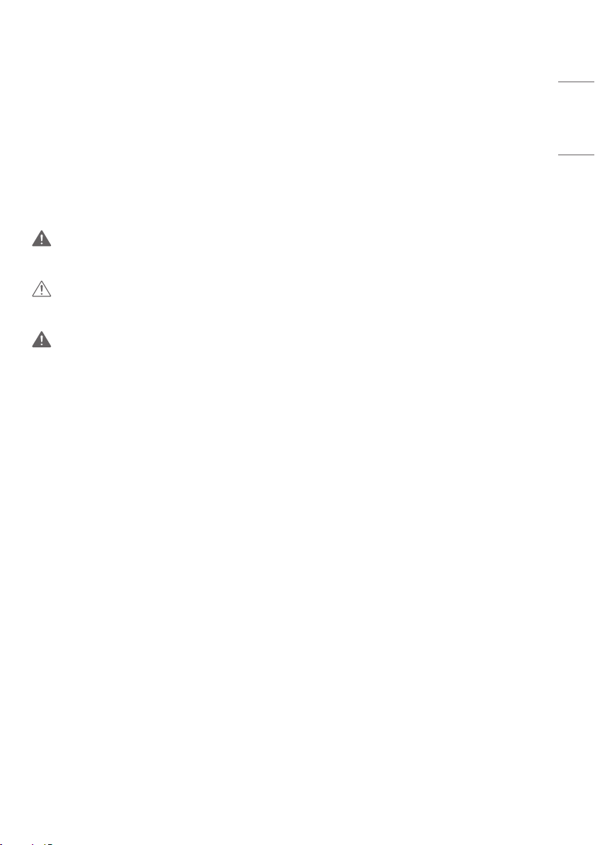
Optional Accessories
Without prior notice, optional accessories are subject to change to improve the performance of the product, and new
accessories may be added. The illustrations in this manual may differ from the actual product and accessories.
Stand
ACC-S-EP5G Bracket
Screws
Diameter 3.0 mm x Pitch 0.5mm x Length 4 mm
(Diameter 0.1 inches x Pitch 0.01 inches x Length 0.1
inches)
Screw
Diameter 4.0 mm x Pitch 0.7 mm x Length 14 mm
(Diameter 0.1 inches x Pitch 0.02 inches x Length 0.5
inches)
NOTE
•
Optional accessories are available for some models. If necessary, please purchase them separately.
15
ENGLISH
Product Installation
Neither a separate stand nor a wall-hanging unit is provided with this product.
CAUTION
•
Disconnect the power cord before moving or installing the monitor to avoid risk of electric shock.
• If you install the monitor on the ceiling, it may fall down and cause an injury. Contact a nearby agency or installation
specialist.
• Do not climb or hang on the product.
NOTE
•
Do not install the product in a place with no ventilation (e.g., on a bookshelf or in a closet) or on a carpet or cushion. If
there is no other option but to mount the product on the wall, make sure that sufficient ventilation is provided before
installation.
- Failure to do so may result in a fire due to the increase in the internal temperature.
WARNING
•
If the monitor is not positioned in a sufficiently stable location, there is a danger that it will fall. Many injuries can be
avoided by taking the following simple precautions.
- Use only fixing instruments and furniture which are able to securely support the product.
- Ensuring the monitor is not overhanging the edge of the supporting furniture.
- Not placing the monitor on tall furniture (for example, cupboards or bookcases) without anchoring both the
furniture and the monitor to a suitable support.
- Not placing cloth or other materials between the monitor and supporting furniture.
- Install the product on a wall on which anchor bolts can be fixed.
- Install the product where it can be safely supported. (On concrete, plywood, MDF, etc.)
CAUTION
16
ENGLISH
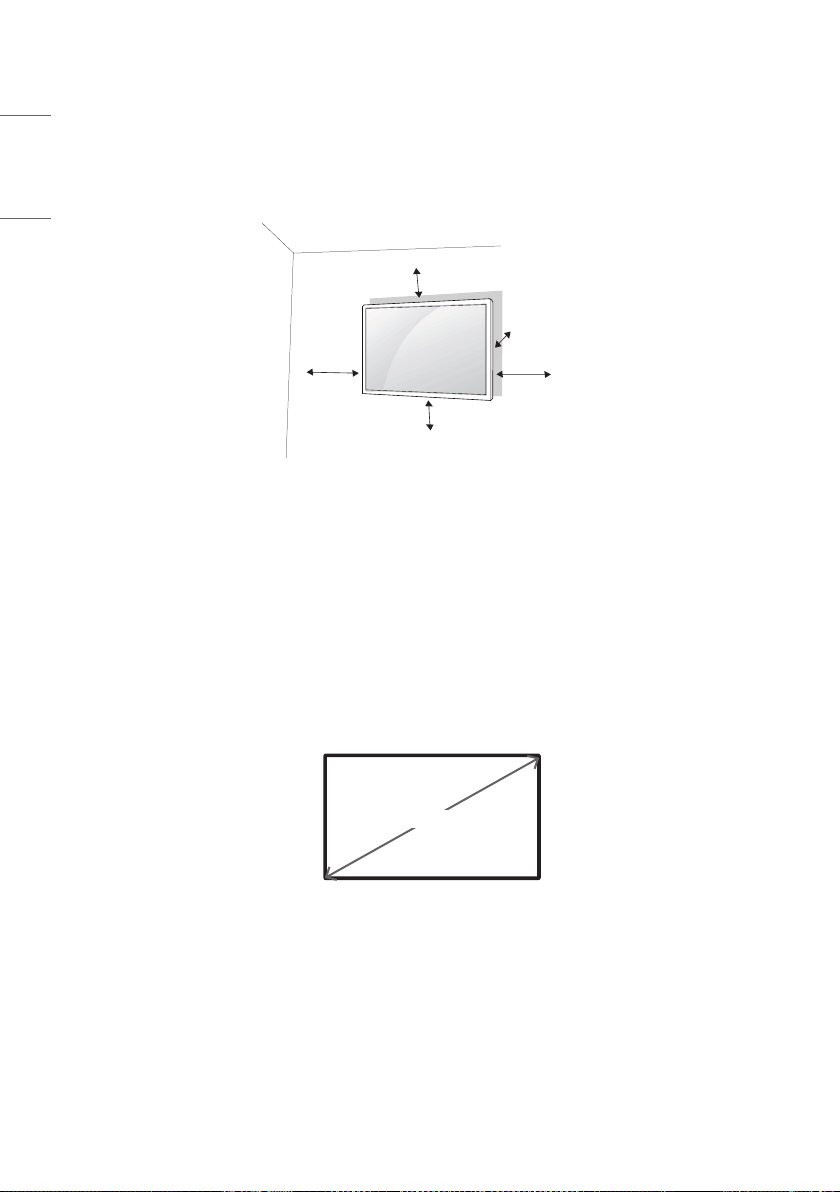
Installing on a Wall
For proper ventilation, allow a clearance of 100 mm (3.9 inches) on each side and from the wall. Detailed installation
instructions are available from your dealer, see the optional Tilt Wall Mounting Bracket Installation and Setup Guide.
100 mm
(3.9 inches)
100mm
100mm
100mm
100mm
To install your monitor on a wall, attach a wall mounting bracket (optional part) to the back of the monitor.
Make sure that the wall mounting bracket is securely fixed to the monitor and to the wall.
1 Use only screws and wall mounting brackets that conform to VESA standards.
2 Screws which are longer than standard length may damage the inside of the monitor.
3 A non-VESA standard screw may damage the product and cause the monitor to fall. LG Electronics is not liable for
any accidents related to the use of non-standard screws.
4 Please use VESA standard as below.
• 785 mm (30.9 inches) and above
* Fixing screws: Diameter 6.0 mm (0.2 inches) x Pitch 1.0 mm (0.03 inches) x Length 14 mm (0.5 inches)
785 mm (30.9 inches)

17
ENGLISH
CAUTION
•
Disconnect the power cord before moving or installing the monitor to avoid risk of electric shock.
• If you install the monitor on a ceiling or slanted wall, it may fall and result in injury. Use an authorized LG wall mount
and contact your local dealer or qualified personnel to assist with the installation.
• Do not over tighten the screws as this may damage the monitor and void your warranty.
• Use only screws and wall mounting brackets that meet the VESA standard. Any damage or injuries caused by misuse
or use of improper accessories are not covered by the warranty.
NOTE
•
The wall mount kit includes the installation guide and all necessary parts.
• The wall mounting bracket is optional. You can obtain additional accessories from your local dealer.
• The length of screws required may differ depending on the wall mount. Be sure to use the correct length.
• For more information, please refer to the guide provided with the wall mount.
18
ENGLISH
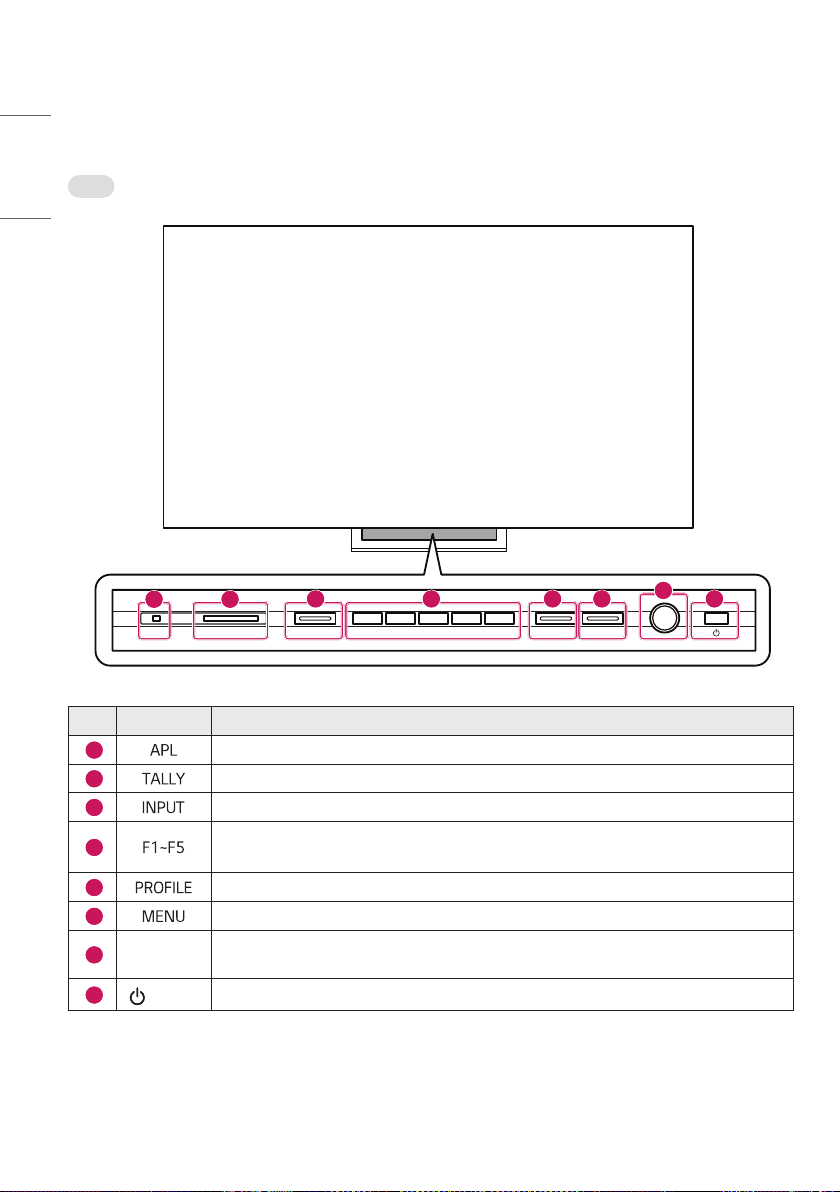
Parts and Buttons
Front
5"--:"1-'''''*/165130'*-&.&/6
1 2
3 5 6 8
7
4
No. Item Explanation
1
The LED flashes red when the panel brightness limit working.
2
Supports tri-Color (red / green / orange) tally LEDs.
3
Changes the input mode. (HDMI, SDI, SFP+, etc.)
4
Frequently used functions can be assigned to the buttons as shortcuts.
- Once a function has been assigned to a button, pressing that button turns on the LED.
5
Saves or loads the monitor settings for each user.
6
Changes the menu or returns to the previous item.
7
Dial Key
The dial can be used to quickly and conveniently move up, down, left, or right. Press the dial
once to select an item.
8
(Power)
Turns the power on or off.
19
ENGLISH
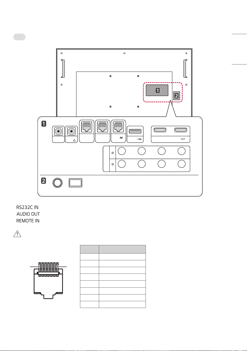
Rear
RS232C
IN
AUDIO
OUT
REMOTE
IN
REMOTE
OUT
SDI
2 1
HDMI(4K@60Hz)IN
IN
OUT
4 3 12
4 3 12
USB IN
LAN
REF IN SFP+
• : Updates and calibrate the software.
• : Outputs sound through headphones.
• : Uses the GPI controller to control the monitor from the outside.
CAUTION
For safety, do not connect the connector for peripheral device wiring that might have excessive voltage to this port.
<Pin Assignment>
Pin Function
1
8
1 Tally R
2 Tally G
3 Maker
4 Safety Area
5 Aspect Ratio
6 Waveform
7 Power Key
8 GND
* You can change the feature of each pin from 1 to 6 in the menu [GPI].
20
ENGLISH
• (RJ45, 8pin): The input signal of the GPI controller can be used as an output.
• : Updates the software.
• : Connects HDMI signal. Please refer to the HDMI supported resolutions page. (Refer to page 72)
• (SDI Input): Connects SDI signal. Please refer to the SDI supported resolution page. (Refer to page 68)
• (SDI Output): Outputs the signal entered through the SDI input terminal. (Loops through the SDI input
signal.)
• : The REF IN is used for analog reference signals black burst and tri-level sync for locking.
• : This is a slot that supports SDI optical signals up to 25Gbps and SDI over IP.
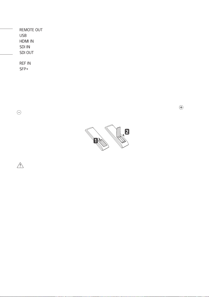
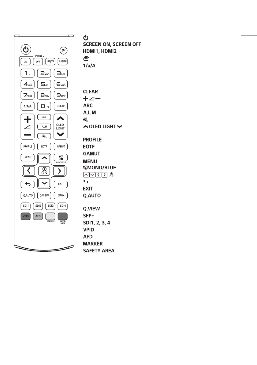
REMOTE CONTROL
The descriptions in this manual are based on the buttons on the remote control. Please read this manual carefully to
usethemonitorcorrectly.Toinstallbatteries,openthebatterycover,placebatteries(1.5VAAA)matching
and
terminals to the labels inside the compartment, and close the battery cover. To remove the batteries, perform the
installation actions in reverse. The illustrations may differ from the actual accessories.
CAUTION
•
Do not mix old and new batteries, as this may damage the remote control.
• Be sure to point the remote control toward the remote control sensor on the monitor.
• Some features of the remote control may not be supported in certain models.
• The product’s internal and external batteries should not be exposed to excessive heat such as direct sunlight, fire, or
the like.
21
ENGLISH
(Power) Turns the monitor on or off.
Turns the image on the monitor on and off.
Selects the HDMI mode.
(Input) Selects the input mode.
Toggles between numerical and alphabetical. (This function is not
supported.)
Number and Alphabet Button Enters numerical or alphabetical characters
depending upon the setting.
Deletes the entered numerical or alphabetical character.
(Volume Control Button) Adjusts the volume of the headphone output.
Selects the screen size.
Turns the Audio Level Meter on or off.
(Mute) Mutes all sounds.
Press the Up / Down button on the remote control to adjust
the OLED brightness.
Enters the Profile menu.
Selects EOTF (gamma).
Selects the Color space.
Enters the main menu.
Changes the Color of the image to black and white / blue.
, After selecting the menu, select and adjust functions.
(Previous) Moves back one step in the user operation feature.
Closes the menu.
Sets the Quad Link mode to Auto mode. (Automatically converts Quad
Link 2SI and Square input.)
Shows the signals of 4 SDI inputs in the multi-view form.
Selects the SFP+ input mode.
Selects the SDI 1, 2, 3, 4 input mode.
Shows the information of the SDI input signal.
Turns the AFD function on or off.
Changes the Maker sequentially.
Changes the Safety Area sequentially.
22
ENGLISH
GETTING READY
• It may take about one minute to initialize the product when the power is turned on for the first time after shipment
from the factory.
• The images of the product in this manual are to aid comprehension and may differ from the actual appearance.
• Various accessories are subject to change or may be added without prior notice to improve the quality of the product.
• Install the product near a socket. When turning off the product, some products may not have a power on / off button,
so turn off the power with the remote control and unplug the power cord.
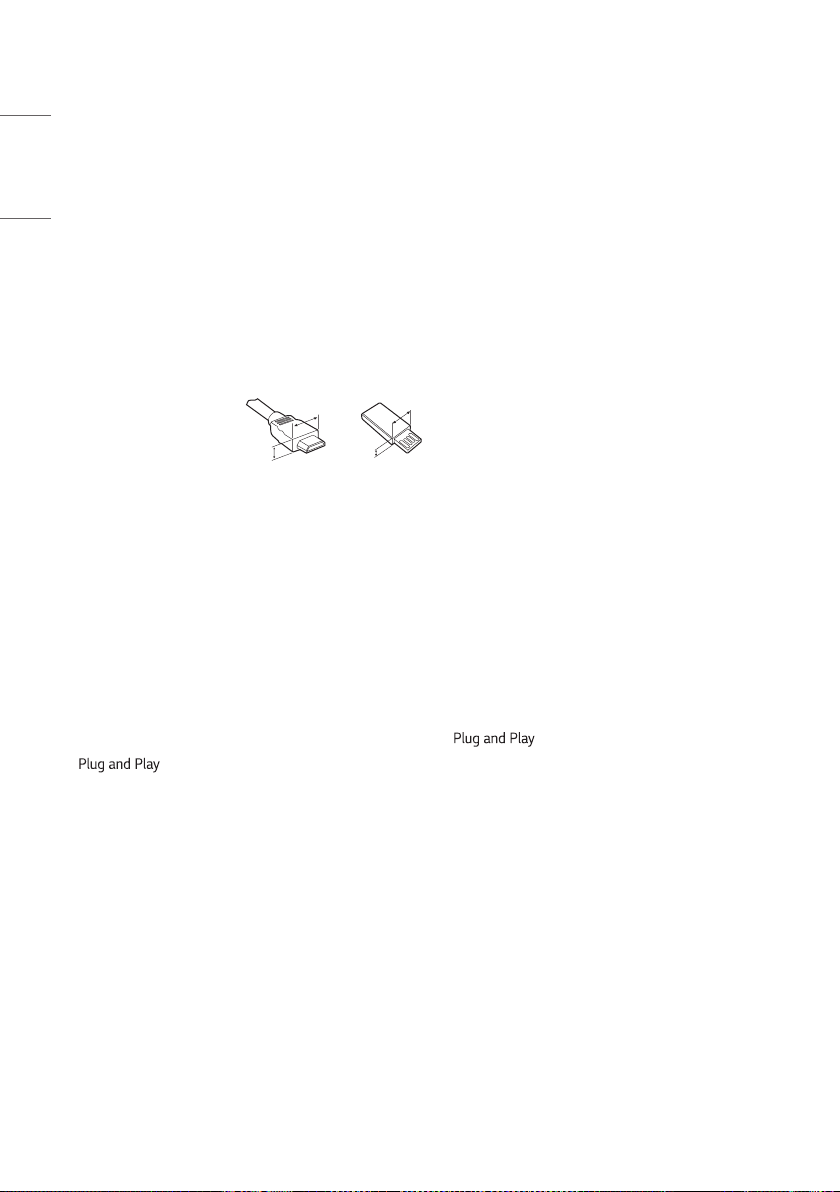
• When connecting an HDMI cable / USB cable or USB memory stick to the HDMI input / USB input terminal, use a
product with a width of 18 mm (0.7 inches) and a thickness of 10 mm (0.3 inches) or less. If the size of the USB
cable or USB memory stick to be used does not match the USB port on your TV, use an extension cable that supports
USB 2.0.
A
B
A
B
* A
<
=
10mm(0.7inches)
* B
<
=
18mm(0.3inches)
MAKING CONNECTIONS
You can connect various external devices to your monitor. Change the input mode and select the external device you
want to connect. For more information about external device connections, see the user manual provided with each
device.
Connecting to a PC
Some of the cables are not provided. This monitor supports the * feature.
*
: a feature that enables a PC to recognise devices attached by the user without device configuration or
user intervention when powering up.
23
ENGLISH
SDI Signal Connection
• Use an SDI standard cable to secure the transmission distance of the SDI signal. (Refer to “PRODUCT
SPECIFICATIONS” on page 66)
• Use in the order of SDI cable connection according to the SDI transmission specifications.
- Single Link 12G / 6G / 3G / HD / SD-SDI and Dual-Link 3G-SDI signals can be input to the SDI IN connectors of this
monitor.
- Up to 2-channel Single Link 12G-SDI signals or 1-channel Dual-Link 3G-SDI signals can be input.
- Use the appropriate input connectors depending on the input signal, referring to the tables below.
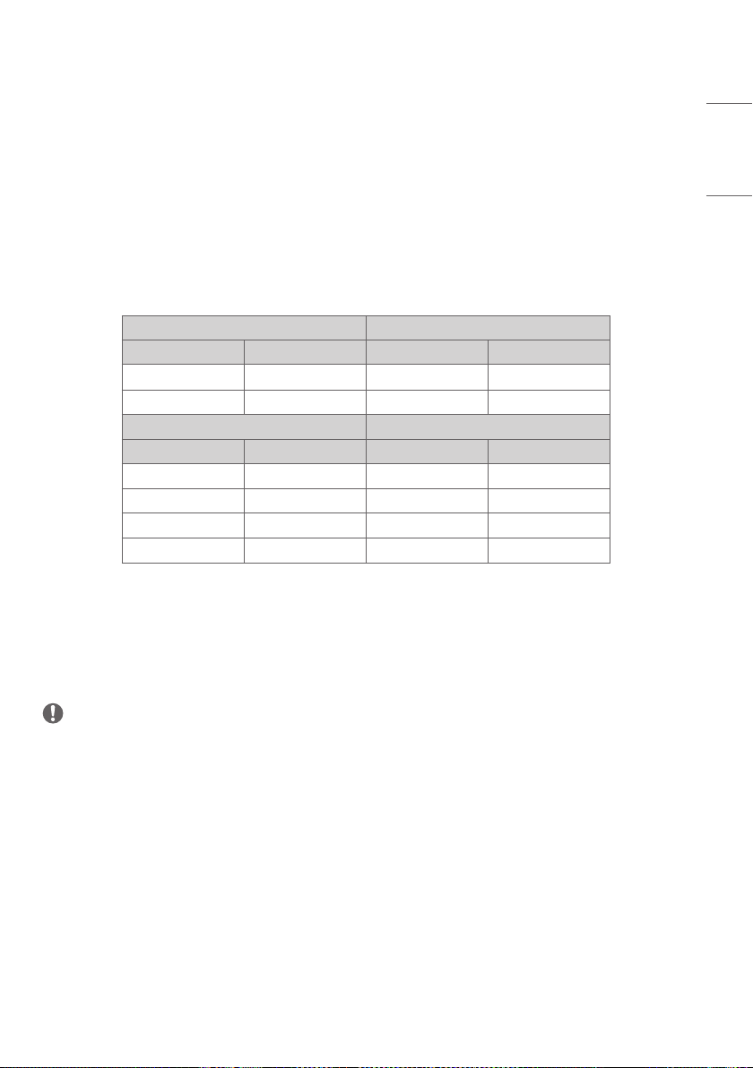
* Examples of SDI Signal Connection
Single Link 12G SDI Dual Link 3G SDI
Connector Input Signal Connector Input Signal
SDI In 1 12G SDI SDI In 1 3G SDI Link1
SDI In 2 12G SDI SDI In 2 3G SDI Link2
Quad Link Square Quad Link 2SI
Connector Input Signal Connector Input Signal
SDI In 1 3G SDI Link1 SDI In 1 3G SDI Link1
SDI In 2 3G SDI Link2 SDI In 2 3G SDI Link2
SDI In 3 3G SDI Link3 SDI In 3 3G SDI Link3
SDI In 4 3G SDI Link4 SDI In 4 3G SDI Link4
External Device Connection
Some of the cables are not provided. Connect a HD receiver, DVD, or VCR player to the monitor and select an
appropriate input mode.
For the best picture and sound quality, connecting external devices to your monitor using HDMI cables is recommended.
NOTE
•
For the best image quality, using the monitor with HDMI connection is recommended.
• To comply with the specifications of the product, use a shielded interface cable with ferrite core, such as a HDMI
cable.
• If you turn the monitor on when the set is cold, the screen may flicker. This is normal.
• Sometimes red, green, or blue spots may appear on the screen. This is normal.
• Use a High Speed HDMI
®
/™ cable (shorter than 3 m (9.8 feet)).
• Use a certified cable with the HDMI logo attached. If you do not use a certified HDMI cable, the screen may not
display or a connection error may occur.
• Recommended HDMI Cable Types
- High Speed HDMI
®
/™ Cable
- High Speed HDMI
®
/™ Cable with Ethernet

24
ENGLISH
• If you cannot hear any sound in HDMI mode please check your PC settings. Some PCs require you to manually change
the default audio output to HDMI.
• You may experience compatibility issues if you use HDMI-PC mode.
• Make sure the power cable is disconnected.
• If you connect a gaming device to the monitor, use the cable provided with the gaming device.
CAUTION
•
Do not press the screen with your finger for a prolonged period as this may result in temporary distortion on the
screen.
• Avoid displaying static images on the screen for a long period of time to prevent image retention. Use a screensaver
if possible.
• A wireless communication device near your monitor can affect the image.
Using the Input List
• HDMI1, HDMI2, SDI1, SDI2, SDI3, SDI4, Dual Link (SDI 1&2), Dual Link (SDI 3&4), Quad Link : Auto, Quad Link : 2SI,
Quad-Link : Square, SDI Quad View, SFP+
25
ENGLISH
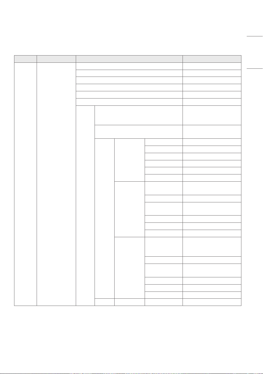
MENU
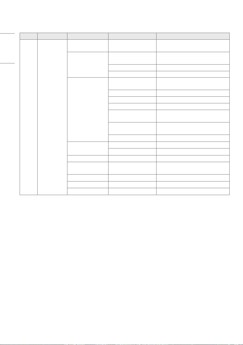
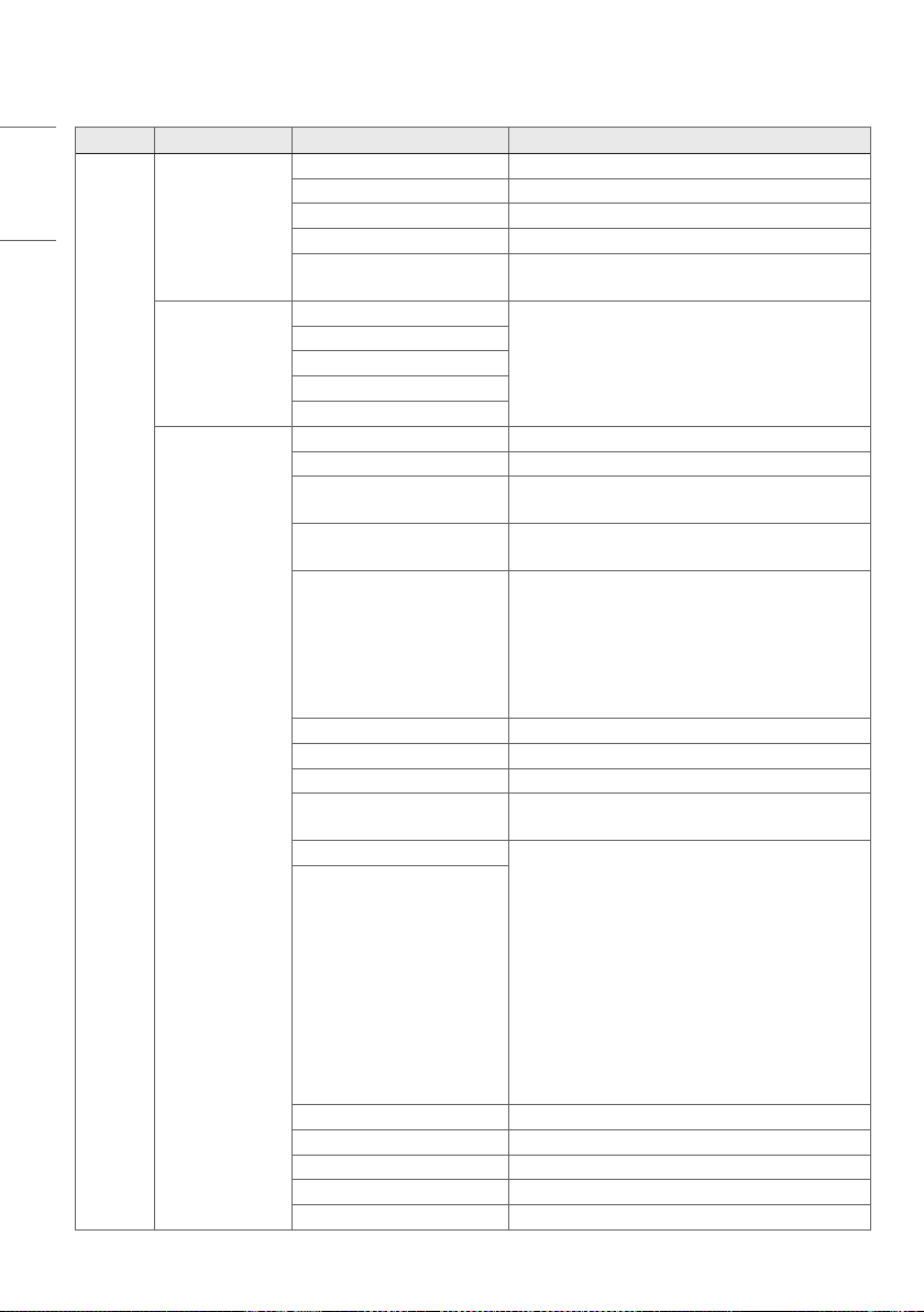
Menu Item 1 Item 2 Value
Picture Color Adjustment
OLED Light 0 ~ 100
Brightness 0 ~ 100
Contrast 0 ~ 100
Chroma 0 ~ 100
Sharpness 0 ~ 50
Tint -50 ~ 50
White
Balance
Control
Color Temp
VAR Temp, 9300K, 5400K,
3200K, D65 (6504K),
D-Cinema (6302K)
VAR Temp 3200K ~ 9300K
Method
2 Points
R-Gain (768) -768 ~ 255
G-Gain (768) -768 ~ 255
B-Gain (768) -768 ~ 255
R-Offset (512) -512 ~ 511
G-Offset (512) -512 ~ 511
B-Offset (512) -512 ~ 511
10 Points IRE
Signal Level(%)
10, 20, 30, 40, 50, 60, 70,
80, 90, 100
Target Luminance 50 ~ 500
Adjusting
Luminance
-50 ~ 50
Red -50 ~ 50
Green -50 ~ 50
Blue -50 ~ 50
22 Points IRE
Signal Level(%)
2.5, 5, 7.5, 10, 15, 20, 25,
30, 35, 40, 45, 50, 60, 65,
70, 75, 80, 85, 90, 95, 100
Target Luminance 50 ~ 500
Adjusting
Luminance
-50 ~ 50
Red -50 ~ 50
Green -50 ~ 50
Blue -50 ~ 50
Reset
26
ENGLISH
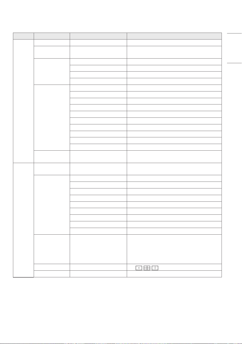
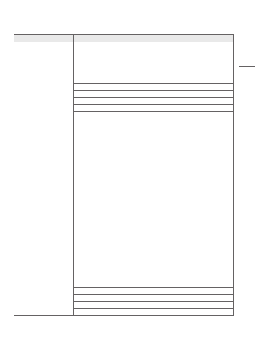
Menu Item 1 Item 2 Item 3 Value
Picture
Display
Configuration
SDR / HDR Signal
Format
Auto , SDR , HDR
SDR Configuration
SDR Gamut
Auto , Native, BT.709 , BT.2020 , sRGB ,
AdobeRGB , P3
SDR EOTF Auto , User , 1.9 , 2.2 , 2.4 , 2.6
SDR EOTF User 0.8 ~ 3.0 (0.1 step)
HDR Configuration
HDR Gamut
Auto , Native, BT.709 , BT.2020 , sRGB ,
AdobeRGB , P3
HDR 1D LUT Factory Default
HDR Format Auto , BT.2100 HLG , ST 2084 PQ
ST 2084 Tone Curve Factory Default
BT.2100 HLG System
Gamma
Factory Default , User
BT.2100 HLG System
Gamma User
1.00 ~ 1.60
HDR Peak Brightness normal, high
Dolby Visioin
Configuration
Dolby Vision 1D LUT Factory Default
Dolby Vision Parameters Factory Default
Transfer Matrix Auto , BT.709 , BT.601 , BT.2020
PQ Clip Point
Panel Peak, 700, 1000, 2000, 3000,
4000, 10000
SDI Color Format Auto , RGB444, YCbCr444 , YCbCr422
Input Range Auto , Narrow , Full , SID Full
Mono / Blue Only Off , Mono Color , Blue Color
27
ENGLISH
Menu Item 1 Item 2 Value
Picture
Over Scan Zero Scan, Over Scan, Under Scan
Aspect Ratio Aspect Ratio
Full Wide, 4 : 3, 14 : 9, 13 : 9, 1.85 : 1, 2.35 : 1,
1 : 1, Original, Auto
Zoom
2xZoom Apply
3xZoom Apply
4xZoom Apply
5xZoom Apply
Picture Option
Noise Reduction Off, Low, Medium, High, Auto
MPEG Noise Reductionn Off, Low, Medium, High, Auto
Real Cinema Enable/Disable
Motion Eye Care Enable/Disable
Dynamic Tone Mapping Enable/Disable
Dynamic Contrast Off, Low, Medium, High
Dynamic Color Off, Low, Medium, High
Smooth Gradation Off, Low, Medium, High
OLED Motion Pro Enable/Disable
Low Luminance Gradation Enable/Disable
Uniformity
Compensation
Enable/Disable, Reset
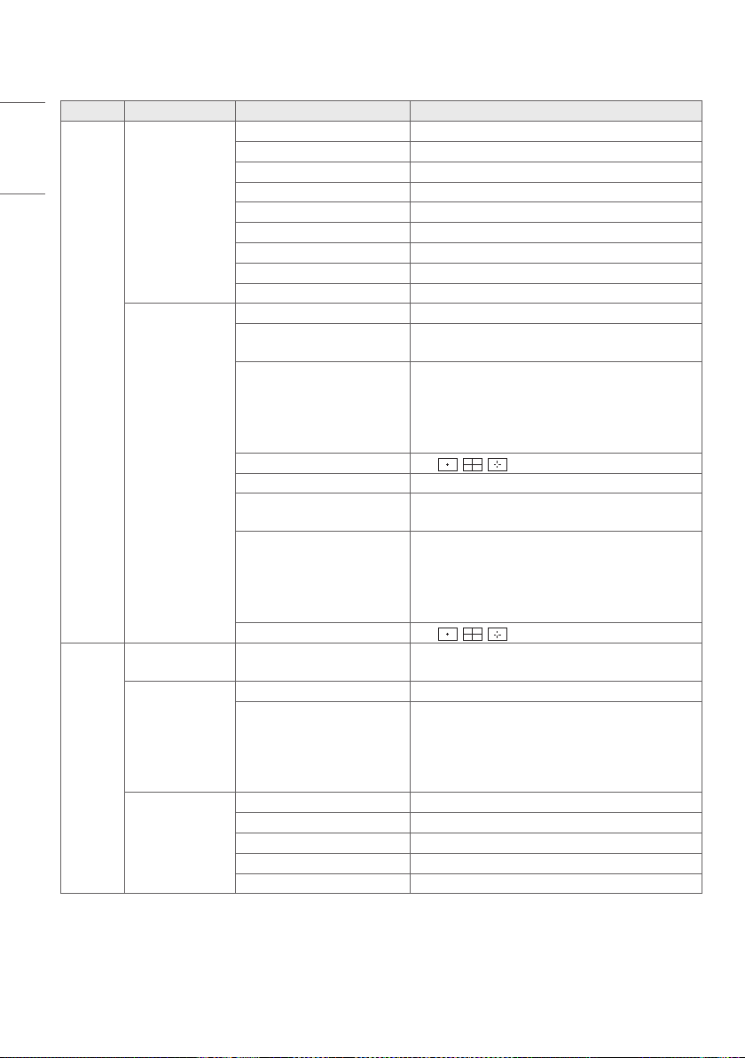
Marker
Marker
Off, 16 : 9, 4 : 3, 14 : 9, 13 : 9, 1.85 : 1, 2.35 : 1,
User Marker 1, User Marker 2, User Marker 3
User Marker
Settings
User Marker 1
Width 0 ~ 3840 (1920)
Height 0 ~ 2160 (1080)
User Marker 2
Width 0 ~ 3840 (1920)
Height 0 ~ 2160 (1080)
User Marker 3
Width 0 ~ 3840 (1920)
Height 0 ~ 2160 (1080)
Safety Area
Off
16 : 9, 95%/ 16 : 9, 93%/ 16 : 9, 90%/ 16 : 9, 88%/
16 : 9, 85%/ 16 : 9, 80%
4 : 3, 95%/ 4 : 3, 93%/ 4 : 3, 90%/ 4 : 3, 88%/ 4 : 3,
85%/ 4 : 3, 80%
Center Marker
Off,
, ,
Marker Thickness 1 ~ 10
28
ENGLISH
Menu Item 1 Item 2 Value
Marker
Marker Color
Marker
Line Color White, Yellow, Blue, Red, Black
BG Color None, Gray, White, Blue, Black
BG Transparency 0%, 20%, 40%, 60%, 80%, 100%
Center Marker Color White, Yellow, Blue, Red, Black
Safety Area
Line Color White, Yellow, Blue, Red, Black
BG Color None, Gray, White, Blue, Black
BG Transparency 0%, 20%, 40%, 60%, 80%, 100%
Preset
Marker Preset 1
Marker Area
Off, 16 : 9, 4 : 3, 14 : 9, 13 : 9, 1.85 : 1, 2.35 : 1,
User Marker 1, User Marker 2, User Marker 3
Safety Area
Off
16 : 9, 95%/ 16 : 9, 93%/ 16 : 9, 90%/ 16 : 9, 88%/
16 : 9, 85%/ 16 : 9, 80%
4 : 3, 95%/ 4 : 3, 93%/ 4 : 3, 90%/ 4 : 3, 88%/ 4 : 3,
85%/ 4 : 3, 80%
Center Marker
Off,
, ,
Marker Preset 2
Marker Area
Off, 16 : 9, 4 : 3, 14 : 9, 13 : 9, 1.85 : 1, 2.35 : 1,
User Marker 1, User Marker 2, User Marker 3
Safety Area
Off
16 : 9, 95%/ 16 : 9, 93%/ 16 : 9, 90%/ 16 : 9, 88%/
16 : 9, 85%/ 16 : 9, 80%
4 : 3, 95%/ 4 : 3, 93%/ 4 : 3, 90%/ 4 : 3, 88%/ 4 : 3,
85%/ 4 : 3, 80%
Center Marker
Off,
, ,
Audio
Audio Source
Selection
SDI1, SDI2, SDI3, SDI4, SFP+
Audio Channel
Settings
Left Channel Off, CH1 ~ 16
Right Channel Off, CH1 ~ 16
Audio Level Meter
Audio Level Meter Enable/Disable
Audio Display Type Horizontal, Vertical
Aidio Channel Selection Full, Group1, Group2, Group3, Group4, User Group
Audio Level Meter Position Top, Middle, Bottom
Audio Level Meter Size Small, Large
29
ENGLISH
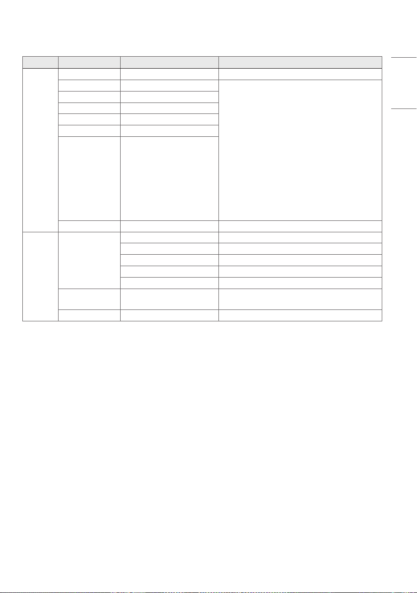
Menu Item 1 Item 2 Value
GPI
GPI Control Enable/Disable
GPI 1 Undefined, Marker Preset 1, Marker Preset 2,
Marker, Center Marker, Safety Area, Tally R, Rally G,
Input HDMI1, Input HDMI2, Input SDI1, Input SDI2,
Input SDI3, Input SDI4,
Input Dual Link (SDI 1&2), Input Dual Link (SDI
3&4),
Input Quad Link: Auto, Input Quad Link: 2SI, Input
Quad Link: Square,
Input SDI Quad View, Input SFP+,
Scan, Aspect Ratio, Menu Key, Enter Key, Up Key,
Down Key,
Function Key 1, Function Key 2, Function Key 3,
Function Key 4, Function Key 5,
Waveform
GPI 2
GPI 3
GPI 4
GPI 5
GPI 6
GPI 7 Power Key
Video
Analysis
Waveform
Waveform Off, WF, VT, WF+VT
Vector Color Enable/Disable
Position Left-Top, Right-Top, Left-Bottom, Right-Bottom
Size Small, Large
Transparency Off, 25%, 50%, 75%
HDR / SDR
Monitoring
Off, 1 Source Mode, 2 Source Mode
Input Source HDMI 1, HDMI 2, SDI 1, SDI 2, SDI 3, SDI 4, SFP+
30
ENGLISH
Menu Item 1 Item 2 Value
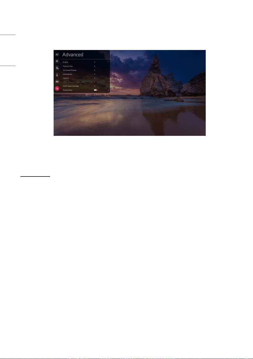
Advanced
Profile
Load Profile Profile1 ~ 10
Save as Profile Profile1 ~ 10
Reset Profile Profile1 ~ 10
Change Profile Password
Option for Loading Saved
Profiles
Load without Entering Password
Function Key
F1
Undefined, Marker, Safety Area, Marker Preset 1,
Marker Preset 2, Aspect Ratio,
Audio Level Meter, Mono / Blue Only, Waveform,
Vector Color, ,Time Code, EOTF, Interlacing / De-
interlacing Mode, Gamut
F2
F3
F4
F5
On Screen Display
Menu Option
Menu Language English, Korean
Menu Position
Center, Left-Top, Right-Top, Left-Bottom, Right-
Bottom
Menu Transparency
0%,10%,20%,30%,40%,50%,60%,70%,
80%,90%,100%
Time Code
Time Code : Off / LTC / VITC
Time Code Size : Small / Large
Time Code Position : Left-Top / Center-Top / Right_
Top / Left_Bottom / Center_Bottom / Right_Bottom
Time Code Transparancy : 0% / 25% / 50% / 100%
VITC Line : Auto / Line 1~31
UMD
UMD Enable/Disable
UMD Character
UMD Position
Left-Top, Center-Top, Right-Top, Left-Bottom,
Center-Bottom, Right-Bottom
UMD FG Color Transparent,
RGB (0,0,0), RGB (255,0,0), RGB (0,255,0), RGB
(0,0,255),
RGB (255,255,0), RGB (255,0,255), RGB
(0,255,255), RGB (255,255,255),
RGB (192,0,0), RGB (0,192,0), RGB (0,0,192),
RGB (192,192,0), RGB (192,0,192), RGB
(0,192,192), RGB (192,192,192),
RGB (128,0,0), RGB (0,128,0), RGB (0,0,128),
RGB (128,128,0), RGB (128,0,128), RGB
(0,128,128), RGB (128,128,128)
UMD BG Color
Input ID Enable/Disable
Details for Input Enable/Disable
ID Style Input Format, Custom Format
Input Label HDMI1 ~ 2, SDI1 ~ 4
VPID Enable/Disable
31
ENGLISH
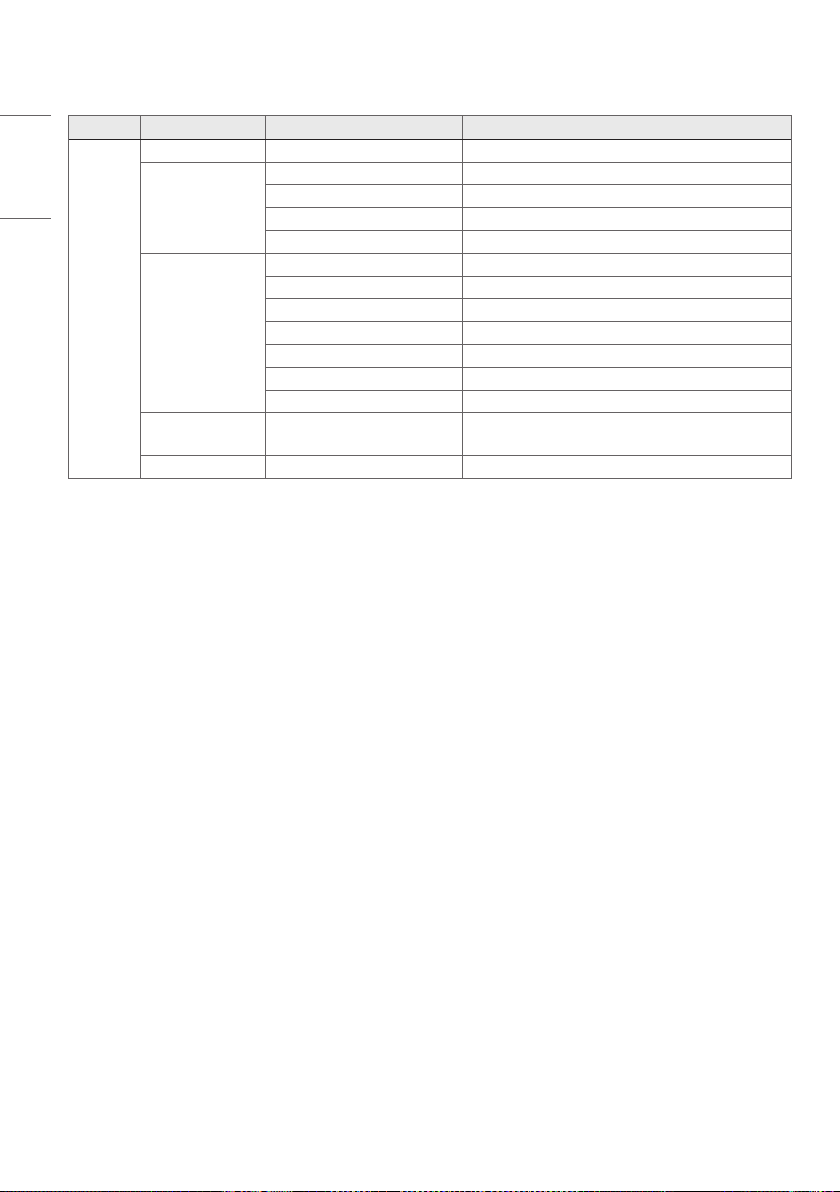
Menu Item 1 Item 2 Value
Advanced
Information
Device Name
Model Name
webOS Version
S/W Version
Serial Number
Micom Version
FPGA Version
Network Settings
Internal Memory
Temperature
Open Source Software Notice
Control
Front LED Enable/Disable
Auto Front Key Lock Enable/Disable
Auto IR Lock Enable/Disable
HDMI Ultra HD
Deep Color
HDMI 1 Enable/Disable
HDMI 2 Enable/Disable
OLED Panel
Settings
TPC Auto-dimming Enable/Disable
Pixel Refresher Operate once when device is off, Start Now
Screen Shift Enable/Disable
Logo Luminance Adjustment Off, Low, High
GSR Auto-dimming Enable/Disable
Convex Power Control Enable/Disable
Screen Saver Enable/Disable
No Signal
Message
Enable/Disable
Genlock Enable/Disable
Screen Control
Interlacing / De-interlacing
Mode
Line Doubler, Inter Field, Field Merge
Internal Pattern
Off, Auto Run, Color Bars, White, Black, Red, Blue,
Green
Power
Standby Mode When No
Signal
Enable/Disable
No IR Power Off (4hour) Enable/Disable
Network Settings
IPv6 Enable/Disable
IP Address
Subnet Mask
Gateway
DNS Server
MAC Address
32
ENGLISH
Menu Item 1 Item 2 Value
Advanced
LG Connect Enable/Disable
Caption
Closed Caption Enable/Disable
Closed Caption Mode 708, 608 ANC, 608 Transcoded
608 Caption Channel CC1
708 Catption Channel Off, Service1
Picture In Picture /
Picture By Picture
PIP/PBP Enable/Disable
Type
Input Source HDMI 1, HDMI2
PIP Position Left-Top, Right-Top, Left-Bottom, Right-Bottom
PIP Transparency 0%, 25%, 50%, 75%
PIP Swap Swap
Audio Select Main, Sub
Change Device
Password
Factory Reset
33
ENGLISH
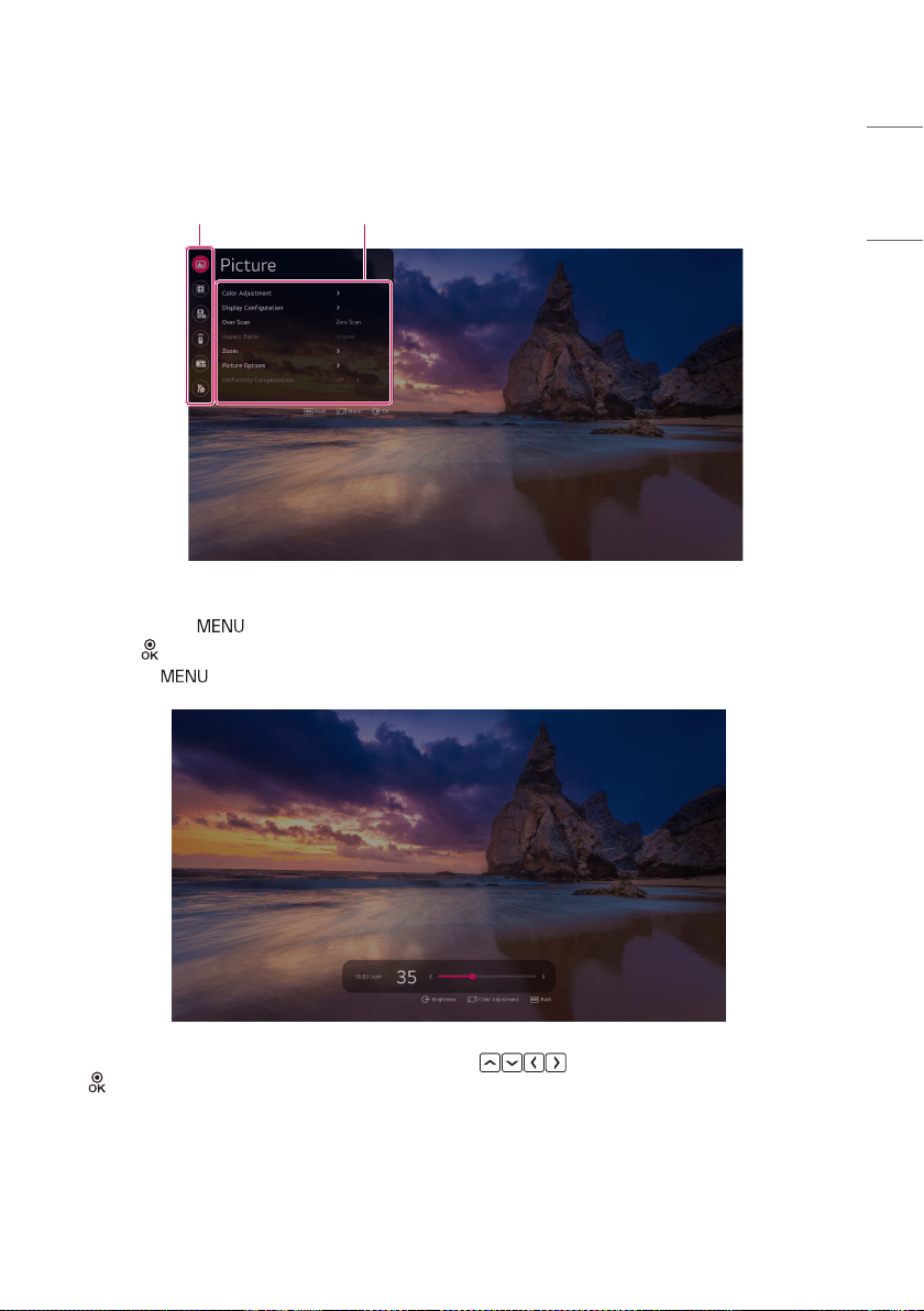
USER SETTINGS
Main Menu
Sub Menu
• How to adjust the menu
- You can press the
button to launch the Settings menu.
- Press the
/ Dial button on the Main menu icon to go to the Submenu.
- Pressing the
button while running the Setup menu moves you to the previous step.
• You can adjust the slider value by moving the remote control’s button or Dial up and down, and press
the
/ Dial button to move to the next slider.
34
ENGLISH
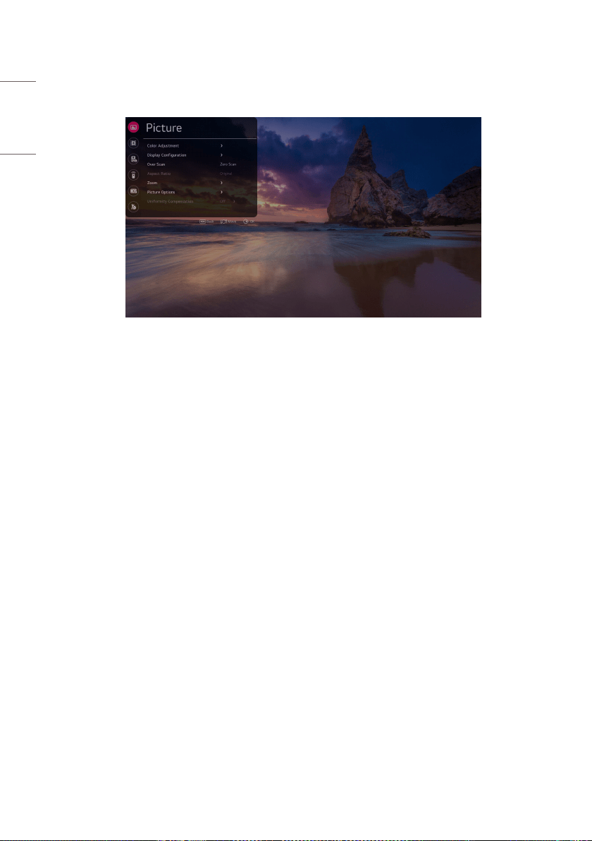
Picture
[Color Adjustment]
• [OLED Light]: Adjusts the brightness of the screen by adjusting the brightness of the OLED panel.
• [Brightness]: Adjusts the overall brightness of the screen. The closer the value to 100, the brighter the screen.
• [Contrast]: Adjusts the difference between the screen’s light and dark areas. The closer the value to 100, the greater
the difference.
• [Chroma]: Softens or deepens the Colors on the screen. The closer the value to 100, the deeper the Color.
• [Sharpness]: Adjusts the sharpness of the edges of objects. The closer the value to 50, the clearer and sharper the
edges.
• [Tint]: Adjusts the balance between the levels of red and green Colors displayed on the screen. The closer to +50, the
deeper the red, and the closer to -50, the deeper the green.
• [White Balance Control]: The function to adjust white balance.
- [Color Temp]: The higher the Color temperature, the cooler the Color. The lower the Color temperature, the warmer
the Color.
- [VAR Temp]: Adjusts the Color temperature to the desired level. Enable this function by setting the [Color Temp]
option to [VAR Temp].
- [Method]: This method is for fine-tuning the color temperature setting, and for select the levels to adjust the color
temperature. If [Method] is set to 2 Points, you can control Gain, Offset. If [Method] is set to 10,22 Points IRE, you
can control white balance at each point of 10, 22 levels of the video.
- Depending upon the selected [Method], the available options may differ. [Signal Level(%)], [Target Luminance],
[Adjust Luminance], [Red/Green/Blue] will be shown, if [Method] is set to 10,22 Points.
- [Signal Level(%)]: Select screen brightness for color temperature adjustment.
- [Target Luminance]: Adjust the luminance to the highest IRE (100 Points).
- [Adjust Luminance]: You can adjust brightness of the selected signal level.

35
ENGLISH
[Display Configuration]
• [SDR / HDR Signal Format]: Select HDR, SDR signal format manually. Auto: use Video Information
- [SDR Configuration]
- [SDR Gamut]: Selects the Color Gamut for SDR input.
- [SDR EOTF]: Selects the EOTF for SDR input.
- [SDR EOTF User]: Adjusts the EOTF in the range of 0.8 ~ 3.0. It can be set in units of 0.1. It is activated when [SDR
EOTF USer] is selected as [User].
• [HDR Configuration]
- [HDR Gamut]: Selects the Color Gamut for HDR input.
- [HDR 1D LUT]: Selects the 1D LUT for HDR input.
- [HDR Format]: selects the HDR format manually. Auto: use Video Information
- [ST 2084 Tone Curve]: selects the ST 2084 Tone Curve
- [BT.2100 HLG System Gamma]: selects the BT.2100 HLG system gamma setting.
- [BT.2100 HLG System Gamma User]: Adjusts the HLG System Gamma in the range of 1.00 ~ 1.60. It can be set in
units of 0.05. It is activated when [BT.2100 HLG System Gamma] is selected as [User].
- [HDR Peak Brightness]: change peak brightness on HDR mode.
• [Dolby Vision Configuration]
- [Dolby Vision 1D LUT]: Selects the 1D LUT for Dolby Vision input.
- [Dolby Vision Parameters]: Selects the Parameters for Dolby Vision input.
NOTE
• [ST.2084 PQ], [BT.2100 HLG], and [Dolby Vision] cannot be selected if [Internal Pattern] is turned on.
• [Transfer Matrix]: Sets the value for colorimetry, which is part of the HDMI Packet AVI Infoframe.
- [Auto]: Sets to the colorimetry value received from the device.
- [BT.601]: Sets the colorimetry value to BT.601.
- [BT.709]: Sets the colorimetry value to BT.709.
- [BT.2020]: Sets the colorimetry value to BT.2020.
NOTE
• This feature works in HDMI, SDI, and SFP+.
• Colorimetry: Data indicating the Color space of the video. It is part of the metadata contained in the HDMI video
format. (e.g., BT.601
SD standard, BT.709 HD / FHD standard, BT.2020 UHD / HDR standard)

36
ENGLISH
• [Mono / Blue Only]
- [Off]: Disables [Mono / Blue Only].
- [Mono Color]: Displays a single Color screen.
- [Blue Color]: Displays only the blue signal on the screen.
• [Input Range]: Correct the darkness and contrast of the screen based on the input signal range. (Settings
recommended based on input signal: RGB 0 – 255: High, RGB 16 – 235: Low, YCbCr: Low, RGB based on SDI Standard
: SDI Full)
Available settings are as follows:
- [Auto]: Use this option to apply settings automatically based on the input signal. (Only one of [Narrow] and [Full] is
selected, [SDI Full] is not automatically selected.)
- [Narrow]: Use this option for input signals in the 8-bit range limited to values 16 – 235 and 10bit range limited to
values 64 - 940.
- [Full]: Use this option for input signals in the 8-bit range full values 0 – 255 and 10bit range full values 0 – 1023.
- [SDI Full]: Use this option for input signals in the 10-bit range limited to values 4 – 1019.
• [PQ Clip Point]: Sets the mastering peak, value, which is part of the HDMI HDR packet metadata.
- [700]: Sets the mastering peak value to 700
- [1000]: Sets the mastering peak value to 1000
- [2000]: Sets the mastering peak value to 2000
- [3000]: Sets the mastering peak value to 3000
- [4000]: Sets the mastering peak value to 4000
- [10000]: Sets the mastering peak value to 10000
NOTE
• This feature works in only HDR10 signal.
NOTE
• HLG is a type of HDR, but the signal packets in this format do not contain metadata. Since the tone curve is fixed
according to the mastering peak information, image quality does not change according to the mastering peak.
• The corresponding settings can be changed with no signals in HDMI, SDI, SFP+ or with signals in SDR / HLG / Dolby;
however, the actual image quality settings are applied when running in HDR.
• [SDI Color Format]: Sets the pixel encoding value, which is part of the SDI Packet AVI Infoframe.
- [Auto]: Sets to the pixel encoding value received from the device.
- [RGB444]: Sets the pixel encoding value to RGB444.
- [YCbCr444]: Sets the pixel encoding value to YCbCr444.
- [YCbCr422]: Sets the pixel encoding value to YCbCr422.
NOTE
• This feature works in SDI and SFP+.

37
ENGLISH
[Over Scan]
Select a scan mode for image output.
• [ZeroScan]:Displays100%oftheoriginalimagesize.
• [OverScan]:Displays95%oftheoriginalimagesize.
• [UnderScan]:Displays105%oftheoriginalimagesize.
NOTE
• [Over Scan] is deactivated when any of the features below have been enabled.
- [HDR / SDR Monitoring]
- [Internal Pattern]
- [PBP]
When deactivated, [Over Scan] is set to [Zero Scan].
[Over Scan] returns to the setting previously set by the user upon reactivation.
• [Over Scan] may work differently depending on the [Screen Shift] settings.
• When using [PIP], this feature applies only to the main screen.

38
ENGLISH
[Aspect Ratio]
The screen size can be adjusted to the set ratio.
• [Full Wide] : Sets the screen size to full wide.
• [4 : 3]: Sets the screen size to 4 : 3.
• [14 : 9]: Sets the screen size to 14 : 9.
• [13 : 9]: Sets the screen size to 13 : 9.
• [1.85 : 1]: Sets the screen size to 1.85 : 1.
• [2.35 : 1]: Sets the screen size to 2.35 : 1.
• [1 : 1]: Sets the screen size to 1 : 1.
• [Original]: Sets the screeen size to original.
• [Auto]: Sets the screen size according to the input source information.
NOTE
• Screen Size can be adjusted sequentially by registering Screen Size values to the Function keys and GPI settings.
• When [Aspect Ratio] is set to [1 : 1], the items below are disabled.
- [Over Scan]
- [Noise Reduction]
- [MPEG Noise Reduction]
- [Real Cinema]
- [Smooth Gradation]
- [Screen Shift]
- [Logo Luminance Adjustment]
- [GSR Auto-dimming]
- [Convex Power Control]
• When [Aspect Ratio] is set to [Auto], If the input source does not have any screen ratio information, the screen
ratio is adjusted to [Full Screen]
• This feature is not available when running [HDR / SDR Monitoring] / [Internal Pattern] / [PBP].
• When using [PIP], this feature applies only to the main screen.

39
ENGLISH
[Zoom]
Zoom into the current external input image.
• [2x Zoom]: The original image is enlarged 2x by dividing the external input into a 2 x 2 grid.
• [3x Zoom]: The original image is enlarged 3x by dividing the external input into a 3 x 3 grid.
• [4x Zoom]: The original image is enlarged 4x by dividing the external input into a 4 x 4 grid.
• [5x Zoom]: The original image is enlarged 5x by dividing the external input into a 5 x 5 grid.
* Supported External Input: HDMI1 - 2, SDI1 - 4, SFP+, SDI Dual Link, Quad Link, Quad View
* When selecting a zoom factor, a square is drawn over the image, indicating the area on which to zoom in.
- Turn the Dial key or use the Up / Down keys on the remote control to change the area on which to zoom in.
- When the Dial key or the OK key on the remote control is pressed, the selected area is enlarged, and the zoom
factor with the currently zoomed area is displayed in the lower left corner of the screen.
- With the image enlarged, turn the Dial key or use the Up / Down keys on the remote control to change the area on
which to zoom in.
- When using the Dial key, turn to the right (clockwise) to move to the right and turn to the left (counter-clockwise)
to move to the left.
- When using the remote control, press the Down / Right keys to move to the right and the Up / Left keys to move to
the left.
- Pressing the Down key while the image is enlarged restores the image and returns to the screen for area selection.
- Pressing the Exit key on the remote control while the image is enlarged closes the zoom settings menu and
restores the image.
NOTE
• The [Zoom] feature cannot be used without a signal or in unsupported resolutions.
• When [Zoom] is applied and GPI signals are entered, the features mapped to the GPIs are as follows:
- Undefined: No action.
- Power Key: Turns power on / off.
- Input Device: Removes [Zoom] and switches input to the corresponding input. If it is the same as the current
input, only [Zoom] is removed.
- Menu Key, Enter Key, Up / Down Key
- Function Key: Removes [Zoom] and executes the feature mapped to the [Function Key].
- [Over Scan], [Aspect Ratio], [Waveform]: Removes [Zoom], returns to the previous screen before applying
[Zoom], and runs the corresponding feature.

40
ENGLISH
[Picture Options]
• [Noise Reduction]: Removes irregularly generated tiny dots for a clearer picture.
• [MPEG Noise Reduction]: Reduces the noise produced during the generation of digital video signals.
• [Real Cinema]: Optimises the screen for movie viewing.
• [Motion Eye Care]: Adjusts brightness and image blurring based on the image information in order to reduce
eyestrain.
• [Dynamic Tone Mapping]: Sets an appropriate contrast according to the image brightness of the HDR content.
• [Dynamic Contrast]: Optimises the difference between the light and dark areas of the screen based on the brightness
of the image.
• [Dynamic Color]: Adjusts the tint and saturation of the image for a more vivid and vibrant display.
• [Smooth Gradation]: Reduces any jagged effect to achieve smooth screen gradation.
[Uniformity Compensation]
Evens out luminance / Color across the panel using SuperSign WB.

41
ENGLISH
Marker
[Marker]
Check the ratio for the image displayed on the screen in advance.
• [Off]: Disables the marker (Default)
• [16 : 9]: Displays a ratio of 16 : 9 (3840 x 2160) on the screen.
• [4 : 3]: Displays a ratio of 4 : 3 (2880 x 2160) on the screen.
• [14 : 9]: Displays a ratio of 14 : 9 (3360 x 2160) on the screen.
• [13 : 9]: Displays a ratio of 13 : 9 (3120 x 2160) on the screen.
• [1.85 : 1]: Displays a ratio of 1.85 : 1 (3840 x 2075) on the screen.
• [2.35 : 1]: Displays a ratio of 2.35 : 1 (3840 x 1634) on the screen.
• [User Marker 1]: Displays the ratio set for Custom Marker 1 on the screen.
• [User Marker 2]: Displays the ratio set for Custom Marker 2 on the screen.
• [User Marker 3]: Displays the ratio set for Custom Marker 3 on the screen.
[User Marker Settings]
Set the ratio for the custom marker.
• Width: Sets the width to be applied to the custom marker. The range can be set in increments of four, from 0 to
3840. (Default: 1920)
• Height: Sets the height to be applied to the custom marker. The range can be set in increments of four, from 0 to
2160. (Default: 1080)

42
ENGLISH
[Safety Area]
Check the scan ratio of images to be displayed on the screen in advance.
• [Off] : Disables the safety zone (Default).
• [16:9,95%]:Displaystheratioof16:9at95%(3648x2052).
• [16:9,93%]:Displaystheratioof16:9at93%(3570x2008).
• [16:9,90%]:Displaystheratioof16:9at90%(3456x1944).
• [16:9,88%]:Displaystheratioof16:9at88%(3378x1900).
• [16:9,85%]:Displaystheratioof16:9at85%(3264x1836).
• [16:9,80%]:Displaystheratioof16:9at80%(3072x1728).
• [4:3,95%]:Displaystheratioof4:3at95%(2736x2052).
• [4:3,93%]:Displaystheratioof4:3at93%(2678x2008).
• [4:3,90%]:Displaystheratioof4:3at90%(2592x1944).
• [4:3,88%]:Displaystheratioof4:3at88%(2534x1900).
• [4:3,85%]:Displaystheratioof4:3at85%(2448x1836).
• [4:3,80%]:Displaystheratioof4:3at80%(2304x1728).
[Center Marker]
Place a marker at the center of the screen.
• [Off]: Disables the center marker (Default).
• [ ]: Sets the Center marker to the type1.
• [ ]: Sets the Center marker to the type2.
• [ ]: Sets the Center marker to the type3.
[Marker Thickness]
Set the thickness of the marker.
The thickness can be set from 1 to 10, with a default value of 1.

43
ENGLISH
[Marker Color]
Set the Color of the marker and the safety zone.
[Line Color]
Set the line Color of the marker.
• [White]: Set the line Color of the marker to white (default).
• [Yellow]: Set the line Color of the marker to yellow.
• [Blue]: Set the line Color of the marker to blue.
• [Red]: Set the line Color of the marker to red.
• [Black]: Set the line Color of the marker to black.
[BG Color]
This feature is used to set the background Color of the marker.
• [None]: No background Color (default)
• [Grey]: Set the background Color of the marker to grey.
• [White]: Set the background Color of the marker to white.
• [Blue]: Set the background Color of the marker to blue.
• [Black]: Set the background Color of the marker to black.
[BG Transparency]
When setting the background Color of the marker, the transparency of the background can be adjusted.
Setinincrementsof20%,rangingfrom0to100%withadefaultvalueof0%.
[Center Marker Color]
Set the line Color of the center marker.
• [White]: Set the line Color of the center marker to white (default).
• [Yellow]: Set the line Color of the center marker to yellow.
• [Blue]: Set the line Color of the center marker to blue.
• [Red]: Set the line Color of the center marker to red.
• [Black]: Set the line Color of the center marker to black.
[Preset]
Save frequently used settings for the marker, safety zone, and center marker as a preset so that they can be applied at
once.
A marker preset can store two values.
44
ENGLISH
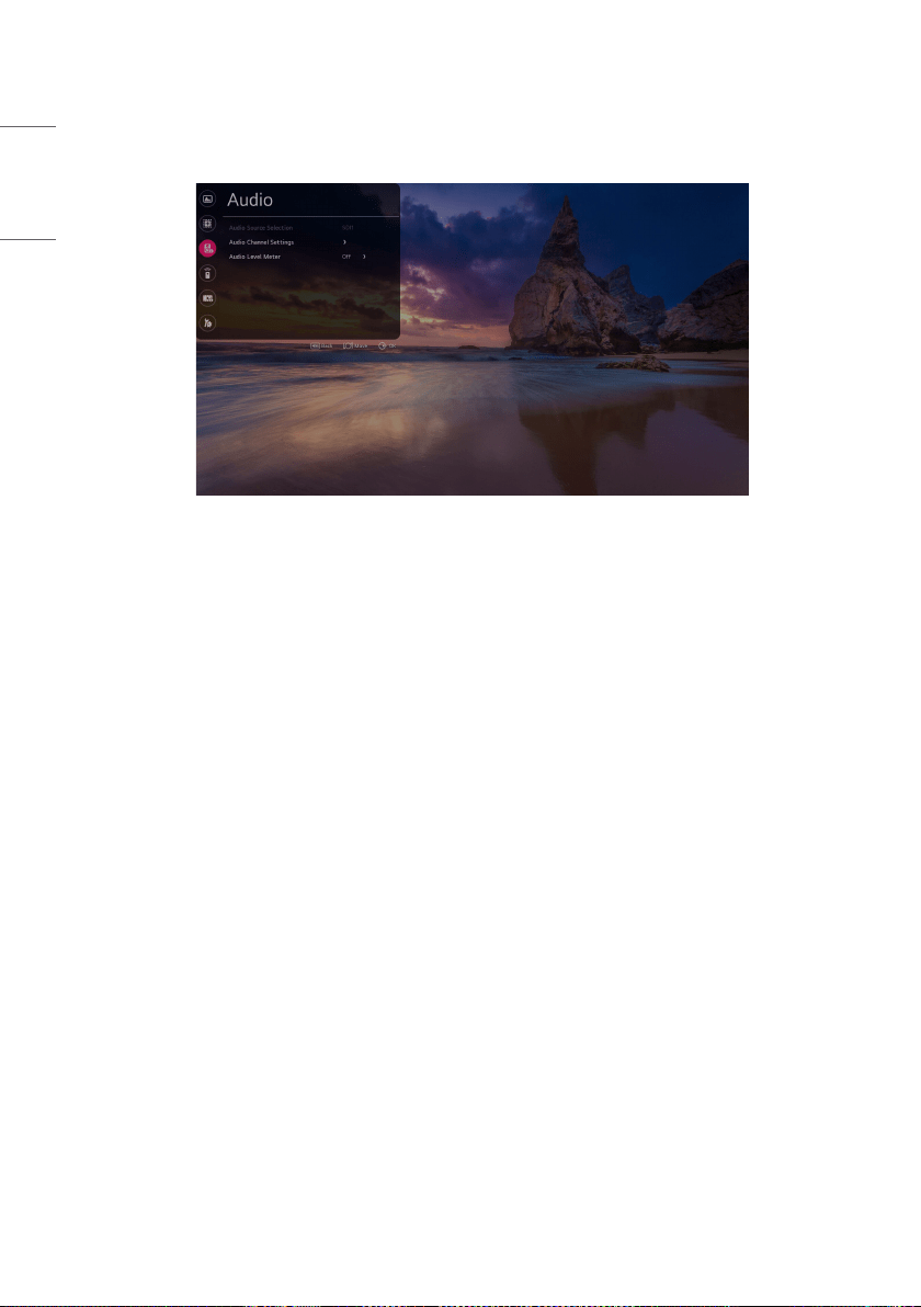
Audio
[Audio Source Selection]
Audio is outputted from the selected SDI input source.
The Audio Level Meter measures the audio level for the corresponding SDI audio and displays it on the screen.
• [SDI1]: Select the SDI1 input source for which to measure the audio level.
• [SDI2]: Select the SDI2 input source for which to measure the audio level.
• [SDI3]: Select the SDI3 input source for which to measure the audio level.
• [SDI4]: Select the SDI4 input source for which to measure the audio level.
• [SFP+]: Select the SFP+ input source for which to measure the audio level.
[Audio Channel Settings]
Select the audio input channel for the preferred headphone output (stereo).
A graph is displayed measuring the audio levels of 16 channels, with eight channels on the left and eight channels on
the right.
• [Left Channel]: Select the audio input channel to output to the left headphone.
• [Right Channel]: Select the audio input channel to output to the right headphone.
45
ENGLISH
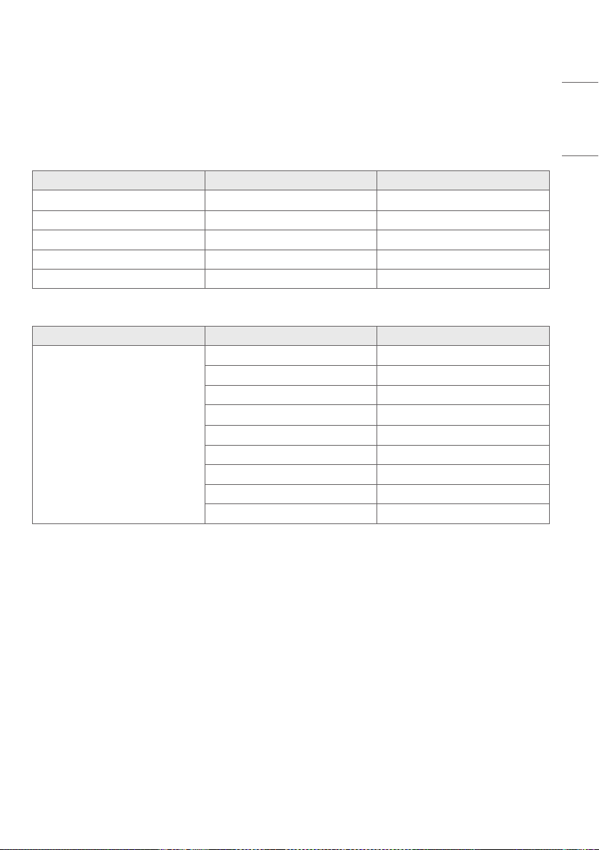
[Audio Level Meter]
• [Audio Level Meter]: Shows audio broadcast signals on the screen through the audio level meter.
• [Audio Level Meter Type] : Select the direction of the bar graph to show the audio level meter on the screen.
• [Audio Channel Selection] : Select the audio channel you want to output on the audio level meter screen.
- The selected Audio Channel Selection value determines the audio channel output on the screen.
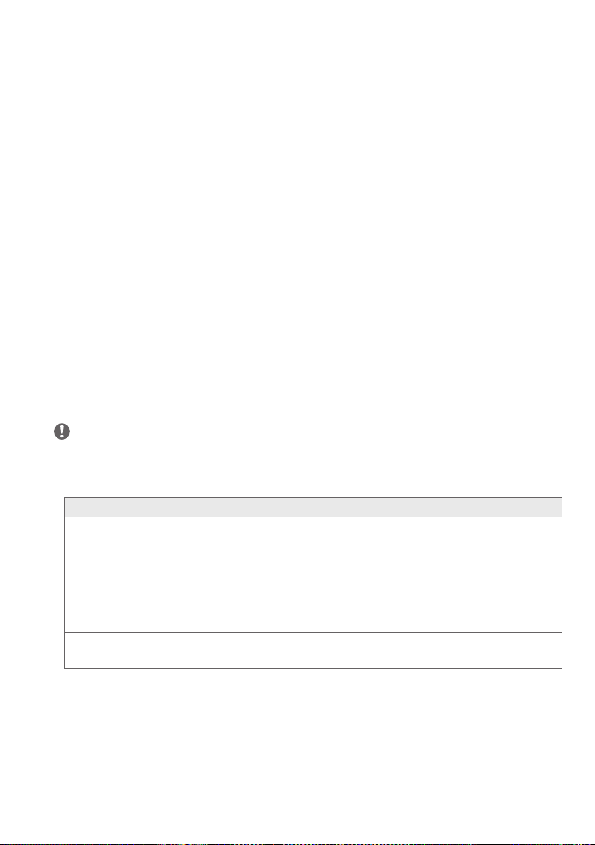
Audio Channel Selection Display on the Left Display on the Right
Full CH1~CH8 CH9~CH16
Group1 CH1+CH2 CH3+CH4
Group2 CH5+CH6 CH7+CH8
Group3 CH9+CH10 CH11+CH12
Group4 CH13+CH14 CH15+CH16
- Set to ‘User Group’ allows to select the audio channel want to output directly on the screen.
Audio Channel Selection Display on the Left Display on the Right
User Group
Off Off
CH1+CH2 CH1+CH2
CH3+CH4 CH3+CH4
CH5+CH6 CH5+CH6
CH7+CH8 CH7+CH8
CH9+CH10 CH9+CH10
CH11+CH12 CH11+CH12
CH13+CH14 CH13+CH14
CH15+CH16 CH15+CH16
• [Audio Level Meter Position]: Select where to display the audio level meter on the screen.
• [Audio Level Meter Size]: Set the size of the bar graph to show the audio level meter on the screen.
46
ENGLISH
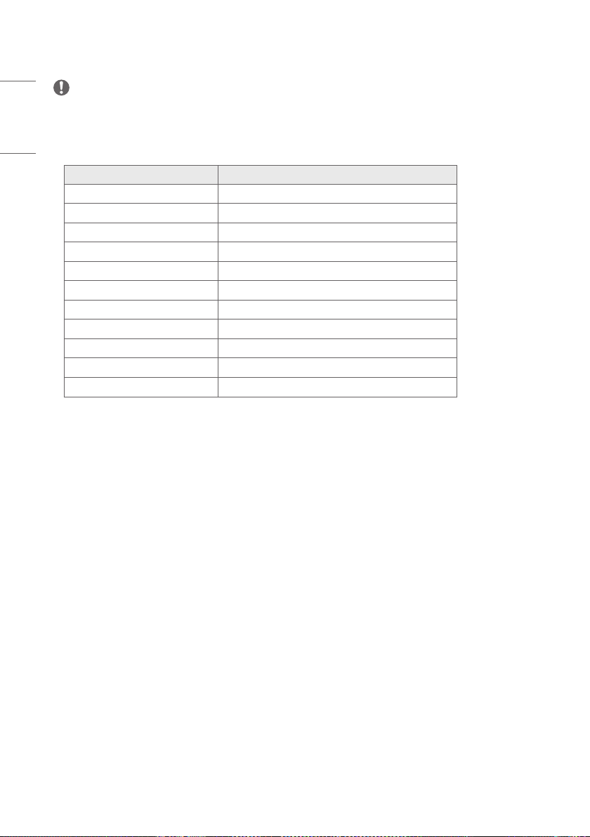
NOTE
• For Quad View output, the audio output and audio level meter output for a specific input source can be selected
from the Audio Source Selection menu.
• For Single Link / Dual Link / Quad Link, the Audio Source Selection menu is disabled, and the feature for selecting
the audio source based on the current input is automatically enabled.
Screen Output Auto-selected in Audio Source
SDI1 SDI1
SDI2 SDI2
SDI3 SDI3
SDI4 SDI4
SFP+ SFP+
Dual Link (SDI1 & 2) SDI1
Dual Link (SDI3 & 4) SDI3
Quad Link: Auto SDI1
Quad Link: 2SI SDI1
Quad Link: Square SDI1
SDI Quad View Previously set Audio Source Selection values
• Audio Level Meter is deactivated if any of the features below have been enabled.
- HDMI Output Screen
- When running Caption / HDR / SDR Monitoring / Waveform
47
ENGLISH
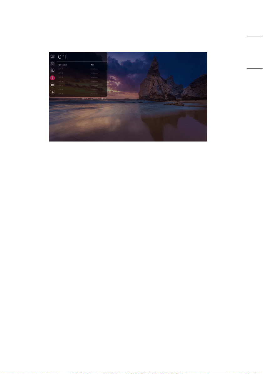
GPI
Assign frequently used features to GPIs (General Purpose Interface) 1 to 7.
Each GPI can send a signal to execute the feature assigned to it.
• The features that can be assigned to GPIs 1 to 6 are as follows:
- [Undefined]: No feature is assigned.
- [Marker Preset 1]: Change the current marker information to the value stored in Marker Preset 1.
- [Marker Preset 2]: Change the current marker information to the value stored in Marker Preset 2.
- [Marker]: Change the marker options.
- [Center Marker]: Set the center marker.
- [Safety Area]: Change the safety zone.
- [Tally R]: Sets Tally R.
- [Tally G]: Sets Tally G.
- [Input HDMI1]: Switches input to HDMI1.
- [Input HDMI2]: Switches input to HDMI2.
- [Input SDI 1]: Switches input to SDI1.
- [Input SDI 2]: Switches input to SDI2.
- [Input SDI 3]: Switches input to SDI3.
- [Input SDI 4]: Switches input to SDI4.
48
ENGLISH
- [Input Dual Link (SDI 1&2)]: Switches input to Dual Link (SDI1 & 2).
- [Input Dual Link (SDI 3&4)]: Switches input to Dual Link (SDI3 & 4).
- [Input Quad Link : Auto]: Switches input to Quad Link: Auto.
- [Input Quad Link : 2SI]: Switches input to Quad Link: 2SI.
- [Input Quad Link : Square]: Switches input to Quad Link: Square.
- [Input SDI Quad View]: Switches input to SDI Quad View.
- [Input SFP+]: Switches input to SFP+.
- [Over Scan]: Change the Scan settings.
- [Aspect Ratio]: Change the Screen Size settings.
- [Menu Key]: Set the Menu key.
- [Enter Key]: Set the OK key.
- [Up Key]: Set the Up key.
- [Down Key]: Set the Down key.
- [Function Key 1]: Set Function key 1.
- [Function Key 2]: Set Function key 2.
- [Function Key 3]: Set Function key 3.
- [Function Key 4]: Set Function key 4.
- [Function Key 5]: Set Function key 5.
- [Waveform]: Change the waveform options.
• GPI 7 is always set as [Power Key].
- [Power Key]: Turns power on or off.
NOTE
• Changing High to Low for a GPI executes the feature assigned to the GPI.
• GPIs cannot be used to execute a disabled feature, even if it is assigned to the GPI.
• When using [Zoom], the actions of the features assigned to GPIs are as follows:
Action Feature
No action. Undefined
Power On / Off Power Key
Turns off Zoom and executes the
feature.
Input HDMI1, Input HDMI2, Input SDI1, Input SDI2, Input SDI3, Input SDI4,
Input Dual Link (SDI1 & 2), Input Quad Link: Auto, Input Quad Link: 2SI, Input
Quad Link: Square, Input SDI Quad View, Input SFP+, Over Scan, Screen Size,
Function key 1, Function key 2, Function key3, Function key 4, Function key
5, Waveform
Feature is executed
while Zoom is turned off.
Marker Preset 1, Marker Preset 2, Marker, Center Marker, Safety Zone, Tally
R, Tally G, Menu key, OK key, Up key, Down key
49
ENGLISH
Video Analysis
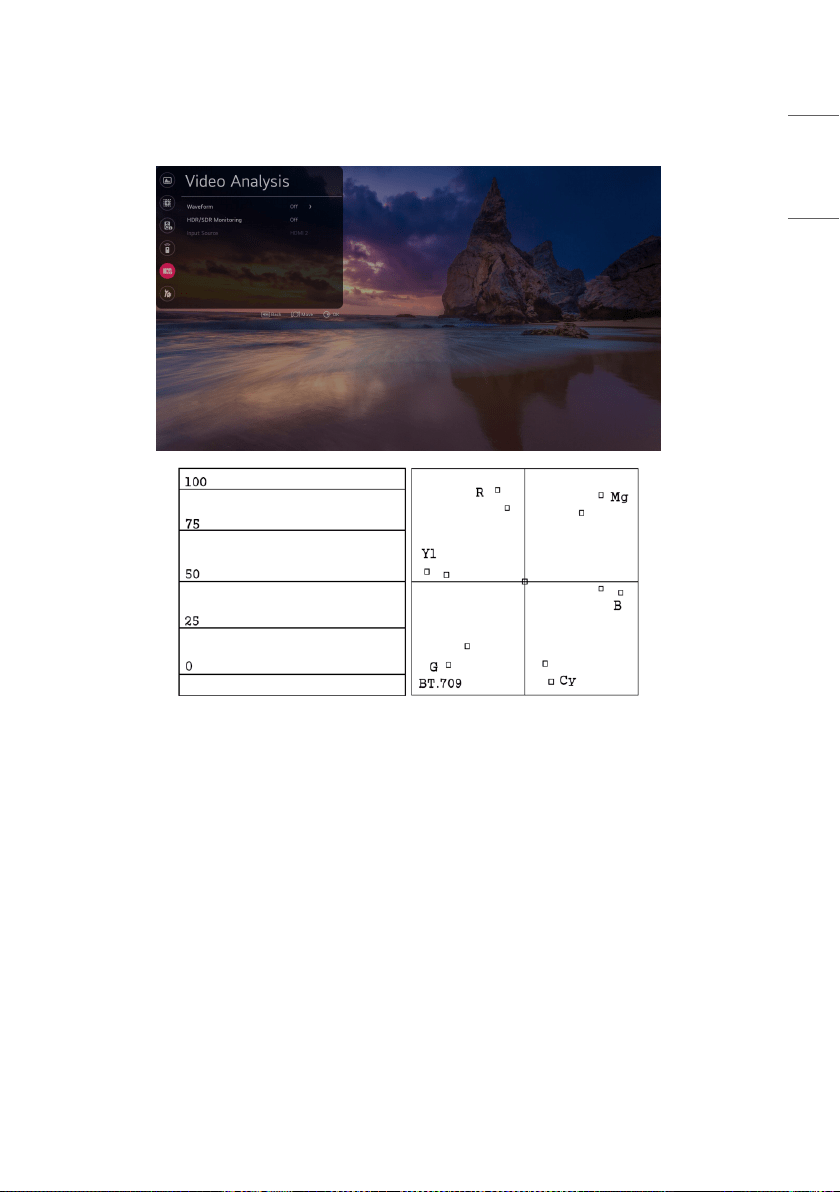
[Waveform]
View the luminance information of the current input picture as a waveform. View the saturation components through a
vectorscope.
Select a graph type.
- [Off]: Turns off Waveform.
- [WF (Waveform)]: Turns on Waveform.
- [VT (Vectorscope)]: Turns on Vectorscope.
- [WF + VT]: Turns on Waveform and Vectorscope.

50
ENGLISH
• [Vector Color]: Select a background Color for the vectorscope.
- [On/Off]: Turns on / off the vectorscope background Color.
• [Position]: Select a location to display the graph.
- [Left-Top]: Set the graph location to the top left corner.
- [Right-Top]: Set the graph location to the top right corner.
- [Left-Bottom]: Set the graph location to the bottom left corner.
- [Right-Bottom]: Set the graph location to the bottom right corner.
• [Size]: Select size of the graph.
- [Small]
- [Large]
• [Transparency]: Adjusts the transparency level of the graph.
- [Off]: Transparency not set.
- [25%]:Setstransparencyto25%.
- [50%]:Setstransparencyto50%.
- [75%]:Setstransparencyto75%.
* Supported Input: SDI1, SDI2, SDI3, SDI4, SFP+, Dual Link, Quad Link
[HDR / SDR Monitoring]
When the input signal for the main screen is HDR, the screen can be divided in half to compare HDR / SDR at the same
time.
• [Off] : Turns off HDR / SDR Monitoring
• [1 Source Mode] : Turns on 1 source HDR / SDR Monitoring
• [2 Source Mode] : Turns on 2 source HDR / SDR Monitoring
NOTE
• Supported Input: HDMI1, HDMI2, SDI1, SDI2, SDI3, SDI4, SFP+, Dual link, Quad link
- Representativeresolution:Supportssignals720p(HD)orhigher.
- Unsupportedresolution:480p(SD)
- If the input signal is not HDR, there is no difference in the image quality of the screen.
- Marked HDR / SDR regardless of the input signal.
- Using [Waveform], [Picture In Picture / Picture By Picture] or [Audio Level Meter] disables this feature.
- Using this feature disables [Over Scan], [Aspect Ratio], and [Zoom].
- HDMI1, HDMI2, SDI1, SDI2, SDI3, SDI4, SFP+, Dual link, and Quad link support HLG and HDR10.
51
ENGLISH
[Input Source]
Select the input to show on the sub screen when HDR / SDR Monitoring is 2 Source Mode
NOTE
• Only the combinations of HDMI and SDI or HDMI and SFP+ are allowed.
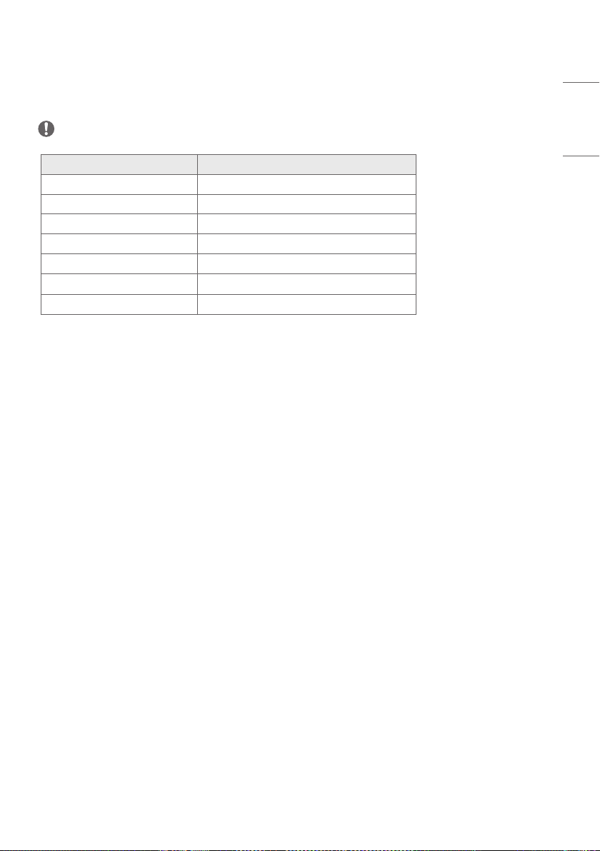
Main Screen Input Sub screen Input List
HDMI1 HDMI2, SDI1, SDI2, SDI3, SDI4, SFP+
HDMI2 HDMI1, SDI1, SDI2, SDI3, SDI4, SFP+
SDI1 HDMI1, HDMI2
SDI2 HDMI1, HDMI2
SDI3 HDMI1, HDMI2
SDI4 HDMI1, HDMI2
SFP+ HDMI1, HDMI2
• The sub screen supports progressive signals only.
• The sub screen does not support SDI interlaced signals.
• The sub screen does not guarantee normal operation of PsF signals.
52
ENGLISH
Advanced Settings
Profile
This feature allows the user to save his or her preferred settings and load them at any time.
[Load Profile]
Retrieve and load specific user settings to the device and make them available by saving them as [Profile].
If no settings have been saved by the user, the default settings are loaded.
• [Profile] saved by the user are displayed as icons.
• When selecting [Profile], a password input window appears at the bottom of the screen. The passwords must match
in order for the selected [Profile] to load.
• The password input window does not appear for [User Settings] that have never been saved.
• After three consecutive failed login attempts, the password input window turns off and returns to the [Load Profile]
screen.

53
ENGLISH
• Items Displayed in User Settings
- OLED Light
- Brightness
- Contrast
- Chroma
- Sharpness
- Tint
- Color Temperature
- SDR Gamut
- SDR EOTF
- HDR Gamut
- HDR 1D LUT
- Dolby Vision 1D LUT
- Dolby Vision Parameters
- PQ Clip Point
- SDI Color Format
- Over Scan
- Aspect Ratio
[Save as Profile]
Save the settings in the current device onto each user setting.
• User Settings saved through the Save User Settings function are displayed as icons.
• When selecting [Profile] to save the current setting, a password input window appears at the bottom of the screen.
The passwords must match in order for the current setting to be saved in the selected [Profile].
• Passwords can be set for [Profile] that have never been saved.
[Reset Profile]
User settings that have been saved by the user are reset and returned to default.
[Change Profile Password]
Change the password for user settings.
• In order to do this, enter the initial password first.
• The initial password can be found in [Change Device Password].
[Option for Loading Saved Profiles]
Set the option for loading saved profiles.
• [Load without Entering Password] : You can load the saved profile without entering a password.

54
ENGLISH
[Function Key]
Assign frequently changed features to the Function keys in the local key bar and use them like hot keys.
Assign features to Function keys 1 to 5, respectively, from the menu.
The features that can be assigned are as follows:
• Undefined: No feature assigned
• Marker: Changes marker options
• Safety Zone: Changes safety zone options.
• Marker Preset 1: Changes the current settings of the marker to those stored in Marker Preset 1.
• Marker Preset 2: Changes the current settings of the marker to those stored in Marker Preset 2.
• Aspect Ratio: Changes screen size options.
• Audio Level Meter: Turns the audio level meter on and off (does not work with HDMI input).
• Solid / Blue Mode: Changes solid / blue mode options.
• Waveform: Changes waveform options (for SDI input only).
• Vectorscope Color: Turns on / off vectorscope Color.
• Time Code: Changes time code options
• EOTF: Changes EOTF options.
• Interlacing / De-interlacing Mode: Changes Interlacing / De-interlacing Mode options.
NOTE
• Only [Marker] is supported when [Internal Pattern] is running.
[On Screen Display]
[Menu Option]
• [Menu Language]: Select the language for the menu.
• [Menu Position]: Select the location for the menu.
• [Menu Transparency]: Sets the background transparency of the menu.
[Time Code]
• [Time Code] : Activates the Time Code feature.
• [Time Code Size]: Sets the Time Code size.
• [Time Code Position]: Sets the Time Code location
- Top Left: Sets the Time Code location to the top left corner.
- Top Center: Sets the Time Code location to the top center.
- Top Right: Sets the Time Code location to the top right corner.
- Bottom Left: Sets the Time Code location to the bottom left corner.
- Bottom Center: Sets the Time Code location to the bottom center. (Default)
- Bottom Right: Sets the Time Code location to the bottom right.
• [Time Code Transparancy]: Sets the background transparency of the Time Code.
• [VITC Line]: Sets the VITC Line

55
ENGLISH
[UMD]
Check which camera is connected and being used to take pictures.
• [UMD] (Toggle On / Off): Activates the UMD feature.
• [UMD Character]: Sets the text for the UMD.
• [UMD Position]: Sets the UMD location.
- Left-Top: Sets the UMD location to the top left corner.
- Center-Top: Sets the UMD location to the top center.
- Right-Top: Sets the UMD location to the top right corner.
- Left-Bottom: Sets the UMD location to the bottom left corner.
- Center-Bottom: Sets the UMD location to the bottom center. (Default)
- Right-Bottom: Sets the UMD location to the bottom right.
• [UMD FG Color]: Sets the text Color of the UMD.
• [UMD BG Color]: Sets the background Color of the UMD.
[Input ID]
• [Details for Input]: View detailed information on the input signal.
- [Off]: Does not show the details of the input.
- [On]: Shows the details of the input.
- HDMI Input: Input Signal, Resolution, Frequency, Color format, Color Space, Black Level, HDR
- Color Format: NODATA, SMPTE170, ITU709, FUTURE
- Color Space: RGB, YCbCr444, YCbCr422, YCbCr420
- Black Level: FULL, LIMITED
- SDI Input: Input Signal, Resolution, Frequency, Colorimetry, Sampling (same information as VPID)
• [ID Style]: Sets how to display the name of the input in the banner.
- Input format: Use the input signal name as it is.
- Custom Format: Use the name set in the input label.
• [Input Label]: Sets the name of the input to be displayed in the banner.

56
ENGLISH
[VPID]
Check the status of SDI signals sent by FPGA.
• [Off]: Does not show SDI signal status.
• [On]: SDI signal status is shown for three seconds and disappears.
NOTE
• Displayed Information
- Transport
- Picture
- Transfer
- Picture Rate
- Aspect Ratio
- Colorimetry (Output value type: Rec. 709 / Rec. 2020 / Rec. 2100)
- Sampling
- Bit Depth
- VPID
• Supported Input Signal: SDI, SFP+
• Some VPID information may not be displayed, depending on the signal.
[Information]
Check the device information.
[Control]
• [Front LED]: Turns on or off all Control Box LEDs.
• [Auto Front Key Lock]: When this feature is set to ON, Front keys will be locked when there is no Front key input for
30 seconds.
- Locks all keys except the Power key.
- Press and hold the Menu key for five seconds to unlock the keys. If this feature is set to OFF, locking does not work,
• even when there is no Front key input.
• [Auto IR Lock]: When this feature is set to ON, the remote control goes into locked mode if there is no remote control
input for three minutes. Unlock the remote control by pressing the numbers 1, 2, 3, and 4 on the remote control in
order. When this feature is set to OFF, locking does not work, even if there is no remote control input.

57
ENGLISH
[HDMI Ultra HD Deep Color]
If the user has a digital input (HDMI1, 2) device connected to one of the ports with adjustable deep Color, UHD Deep
Color On (6G) or Off (3G) can be selected from the ULTRA Deep Color Settings menu.
IfcompatibilityissuesoccurwiththegraphicscardwhentheDeepColoroptionissettoOnat3840x2160@60Hz,
set the option to Off.
• HDMI inputs 1 and 2 are best suited for 4K at 60 Hz (4:4:4, 4:2:2) to enjoy high definition video. However, video or
audio may not be supported, depending on the specifications of the external devices. In that case, please connect to
another HDMI port.
[OLED Panel Settings]
• [TPC(TemporalPeak Luminance Control) Auto-dimming]: Lowers the brightness to protect the screen when a static
image is detected.
• [Pixel Refresher]: Corrects any issues that may arise on the screen when the TV has been turned on for a long time.
This may take more than an hour.
• [Screen Shift]: Moves the screen slightly at regular intervals to prevent image sticking on the display panel.
• [Logo Luminance Adjustment]: Adjusts the luminance of static images such as on-screen logos to correct potential
screen issues.
• [GSR (Global Sticky Reduction) Auto-dimming]: Gradually reduces the luminance of the screen when a specific area
on the screen has a fixed image for a certain period of time without changing.
• [ConvexPowerControl]:Thebrightnessofthecentralpartofthescreenisexpressedas100%,andthefartheraway
from the center, the darker it is because of the Gradation Gain applied to the image for reducing power consumption.
NOTE
The features below may work differently depending on [Screen Shift] settings.
• [Aspect Ratio] and [Over Scan] Behaviour
- When [Over Scan] is set to [Zero Scan], the features behave as follows, depending on [Aspect Ratio]:
When [Aspect Ratio] is set to [16:9] → The existing screen settings apply, regardless of [Screen Shift]
settings.
When [Aspect Ratio] is set to a value other than [16:9] → The image is enlarged when [Screen Shift] is set to
[On].
- When [Over Scan] is set to [Over Scan] → The image is enlarged when [Screen Shift] is set to [On].
- When [Over Scan] is set to [Under Scan] → The image is enlarged when [Screen Shift] is set to [On].
• [Zoom]
- When [Screen Shift] is set to [On], the area set for [Zoom] moves along whenever the screen moves.
• [Marker]
- When [Screen Shift] is set to [On], the area indicated by [Marker] moves along whenever the screen moves.

58
ENGLISH
[Screen Saver]
• Prevent afterimage or overuse of panels using the screen protection feature when there is no signal.
• On:Runsthescreensaverifthereisnosignalfor130seconds(default)
• Off: Screensaver is disabled.
[No Signal Message]
Set the [no signal message] function to On or Off.
• On: Enable no signal message (default).
• Off: Disable no signal message.
[Genlock]
When the Genlock signal is connected to the REF IN port and the Genlock feature is turned on, the monitor can use the
video signal synchronisation feature.
[Screen Control]
[Interlacing / De-interlacing Mode]
Set the output mode for interlaced pictures.
• Line Doubler: Mode that outputs the top / bottom fields of interlaced signals by processing them to be vertically
doubled
• Inter Field: Mode that outputs only the top fields of interlaced signals by processing them to be vertically doubled
• Field Merge: Mode for deinterlacing the interlaced signals
[Internal Pattern]
• This feature is used to show patterns stored in the device.
• Off: Turns off the internal pattern feature. (Default)
• Auto Run: Shows internal patterns in order at five second intervals. (Color bar - White - Black - Red - Blue - Green -
Color Bar...)
• Color Bar: Shows the Color bar pattern.
• White: Shows the white pattern.
• Black: Shows the black pattern.
• Red: Shows the red pattern.
• Blue: Shows the blue pattern.
• Green: Shows the green pattern.

59
ENGLISH
[Power]
[Standby Mode When No Signal]
Set whether or not to enable the feature for forcing shutdown after ten seconds.
• The feature is set to [On] or [Off].
• When set to [On], the product turns off if there is no signal for ten seconds.
• When set to [Off], the feature for forcing shutdown after ten seconds is disabled.
• It is recommended that the feature be set to [Off] when the product is to be used for a long time since it is a power-
off function.
[No IR Power Off (4hour)]
Set whether or not to enable the feature for forcing shutdown after four hours.
• The feature is set to [On] or [Off].
• When set to [On], the product turns off when there is no input from the remote control for four hours.
• When set to [Off], the feature for forcing shutdown after four hours is disabled.
• It is recommended that the feature be set to [Off] when the product is to be used for a long time because it is a
power-off function.
[Network Settings]
Connect to the Local Area Network (LAN) through the LAN port, and set up the network. Once a physical connection is
established, the device automatically connects to most networks without any adjustment. In some networks, the device
settings may need to be adjusted. For more information, contact your Internet service provider or refer to the router’s
manual.
NOTE
• If connected to a network that supports IPv6, it is also possible to view IPv6 network connection information from
a wired network connection. However, IPv6 connections only support automatic connections.
[LG Connect]
• Sets the [LG Connect] function to On or Off.
• You can connect device via Promota, Calman API and WebApp API.
• Default setting is ‘Off’.
[Caption]
This feature is used to show closed captions on the screen.
• Closed Caption (Toggle On / Off): Enable closed captions.
• Closed Caption Mode: 708 / 608 Transcoded / 608 ANC captions are available for selection.
• 608 Caption Channel: CC1
• 708 Caption Service: off/Service1
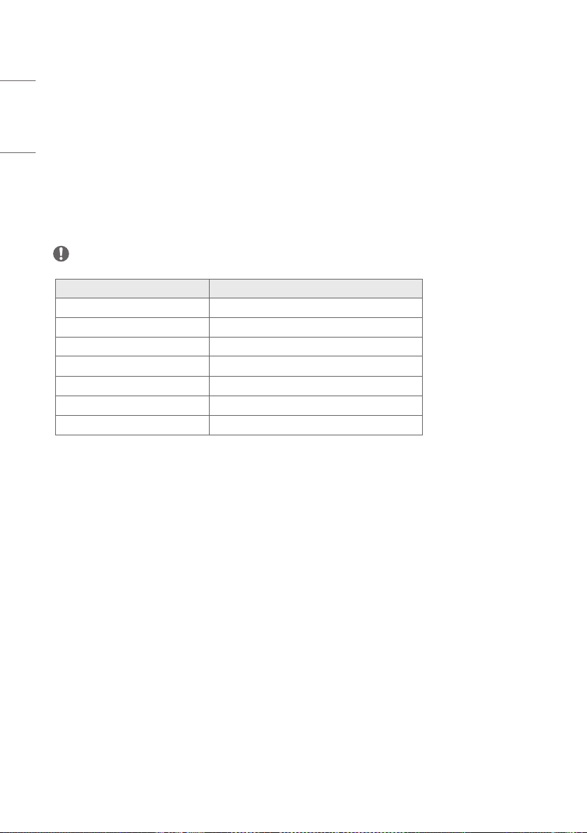
60
ENGLISH
[Picture In Picture / Picture By Picture]
• [PIP / PBP]: Output an image from another input source to the sub screen.
- [On]: Enables PIP / PBP.
- [Off]: Disables PIP / PBP.
• [Type]: Sets the size of the sub screen.
• [Input Source]: Select the input to show on the sub screen.
• [PIP Position]: The location of the sub screen can be set when [Type] is PIP.
• [PIP Transparency]: The transparency of the sub screen can be set when [Type] is PIP.
• [PIP Swap]: It is possible to switch between the main screen and sub screen when [Type] is PIP.
• [Audio Select]: It is possible to select from the main screen audio and sub screen audio.
NOTE
• Only the combinations of HDMI and SDI or HDMI and SFP+ are allowed.
Main Screen Input Sub screen Input List
HDMI1 HDMI2, SDI1, SDI2, SDI3, SDI4, SFP+
HDMI2 HDMI1, SDI1, SDI2, SDI3, SDI4, SFP+
SDI1 HDMI1, HDMI2
SDI2 HDMI1, HDMI2
SDI3 HDMI1, HDMI2
SDI4 HDMI1, HDMI2
SFP+ HDMI1, HDMI2
• The sub screen supports progressive signals only.
• The sub screen does not support SDI interlaced signals.
• The sub screen does not guarantee normal operation of PsF signals.
[Change Device Password]
Change the password used in the Settings menu. (Initial Password: 000000)
[Factory Reset]
All settings in [Settings] and internal memory files are reset.

61
ENGLISH
Calibration
[CalMan Support]
The 65EP5G supports automated color calibration using CalMan software by Portrait Displays, Inc. (purchased
separately:
https://www.portrait.com/calman-calibration-software/
). CalMan uto-calibration adjusts the monitor’s
internal 1D and 3D LUTs for precise color calibration.
Ensure the monitor and PC with CalMan are connected to the same local area network (LAN). Select the “Display
Specific
Autocal – LG” workflow in CalMan and follow CalMan’s instructions to calibrate the monitor. Connecting to
CalMan will require the 65EP5G’s IP Address. Once the monitor is connected to LAN, navigate in the 65EP5G menu to
“Advanced Network Settings” to view the IP Address.
Each of the 65EP5G’s 10 Profiles can be calibrated separately, in both SDR and HDR mode, by selecting the profile
number in CalMan. Once a profile has been calibrated, it can be selected through the monitor’s menu under “Advanced
Profile”. Profile selection may also be assigned to a Function Key.
NOTE
• CalMan does not support connections via IPv6.
[Colorimeter Profiling]
When a colorimeter is used to measure displays, best practice is to calibrate the colorimeter to each individual display
using a more accurate device. This practice called colorimeter profiling. The typical method of colorimeter profiling uses
a 3x3 correction matrix to account for errors in the colorimeter’s spectral response to a display’s three primary light
elements. Colorimeter profiling functionality is often included in software provided with the measurement device and in
display calibration software.
The 65EP5G panel uses a white sub-pixel in addition to red, green, and blue sub-pixels. Because the panel has four
light elements, the traditional method of colorimeter profiling using a single 3x3 matrix can cause large measurement
errors when used with the 65EP5G. When profiling a colorimeter for the 65EP5G, an approach called the Three-Matrix
Method (or “Bodner Method”) should be used to achieve accurate measurements. This approach is supported in
CalMan with the “Tools
Meter Profiling” workflow, by selecting “Bodner Method (RGBW OLED)” for the “Generate
Profile Matrix” setting on the “Create Meter Profile” page.

62
ENGLISH
[Metameric Offset]
The perceived white point of the 65EP5G may not match the measured white point. The mismatch is a result of
observer metamerism, which affects all wide color gamut displays in this way. Two calibrated displays may visually
appear to have different white points despite having the same measured chromaticity, due to a difference in their
spectral emittance. White points that visually match between displays for one person may be a visual mismatch for a
different person.
To account for observer metamerism, the white point of the 65EP5G can be fine-tuned after calibration to visually
match the white point of second monitor using these steps:
• Calibrate the 65EP5G in Calman, using the same target white point and luminance as the second monitor
• Display a white patch on both the 65EP5G and the second monitor
• In the 65EP5G menu, navigate to the “Picture Color” menu
• Change the “Color Temp” setting to “VAR Temp”
• Adjust the “R-Gain”, “G-Gain”, and “B-Gain” settings until the white point of the 65EP5G visually matches the white
point of the second monitor
• Adjusting the RGB Offset controls is not recommended for white point adjustment

63
ENGLISH
TROUBLESHOOTING
Ů Each model may have different points to check.
Ů For information on your PC settings, refer to the Windows Help.
Issues Related to Use
• The power won’t turn on.
- Check if the power cord is correctly plugged into the power outlet.
- Try turning the power on after disconnecting the AC adapter and cleaning the contacting port.
• The ‘Unknown Product’ message appears when the product is connected.
- Check if the driver of PC (graphics card) has been installed.
- Check if the plug and play function is supported by the PC (graphics card) user manual.
Issues Related to Screen (Video)
• A message saying ‘No signal’ or ‘Invalid Format’ appears.
- The signal cable is not connected between the PC and the product, or the cable connection status is unstable.
Check the signal cable.
- Access the input menu to check the input signal.
- The signal from the PC (Graphics card) is out of the vertical or horizontal frequency range of the product. Adjust
the frequency range by referring to the specifications in this manual.
• The position of the screen is incorrect.
- Check if the graphics card resolution and frequency are supported by the product. If the frequency exceeds the
supported range, use PC settings to set the resolution to the recommended value.
• The screen is displayed abnormally.
- Connect the signal cable that matches with the source input signal.
• Images are flickering or fluttering on the screen.
- If you turn the monitor on when it is cold, the screen may flicker. This is normal.
- Make sure that the current resolution and frequency settings of the graphics card are supported by the monitor.

64
ENGLISH
Issues Related to Screen (Color)
• Screen has poor Color resolution (16 Colors).
- UsePCsettingstosettheColorto24bits(TrueColor)orabove.
• Screen Color is unstable or mono-Colored.
- Check the connection status of the signal cable. Or, re-insert the PC graphics card.
• Black spots or bright spots appear on the screen.
- Some pixels (red, green, blue, black) are visible on the screen due to the unique characteristics of the display panel.
This is not a malfunction of the product.
• The screen’s brightness seems dark.
- Adjust brightness and contrast again.
Issues Related to Sound
• There is no sound output.
- Adjust the volume of the product or external device.
- See if the sound is set properly.
• Sound is too low.
- Adjust the volume of the product or external device.
• For some models, you will need to purchase external speakers separately since they do not have speakers built-in.

65
ENGLISH
Other Issues
• The power suddenly turned off.
- Check if the auto-off function is activated on the settings related time.
- Power source has not being supplied properly. See if the product power cord is connected properly.
- Check the power control settings.
OLED Image sticking
• Since after-image can occur when a specific fixed screen is used for a long time, to reduce after-images, it is
recommended not to exceed the recommended daily operation time set for the screen size and to display the video
content with a small number of fixed characters or logos.
Recommendeddailyoperationtime(65inches:12hours)
• [Pixel Refresher]: Correct issues that may arise on the screen when it is turned on for a long period of time.
• A few horizontal lines may appear on the screens while running the [Pixel Refresher] feature. This is normal, so
there is no need for concern. If the power is turned on or a power failure occurs while the [Pixel Refresher] feature is
running, the feature may not work properly.
• Turn power on seven minutes after running [Pixel Refresher].
• The external speakers connected to the product may make a sound while you are running the [Pixel Refresher]
feature.
• Use screen protection mode settings([TPC Auto-dimming], [Screen Shift], [Logo Luminance Adjustment], [GSR
Auto-dimming], [Convex Power Control]) feature in [OLED Panel Settings] to effectively prevent the formation of an
after-image.
• Using the product for a long time under the following conditions may damage the screen and leave an afterimage, so
please use it with caution.
- Specific fixed screen
- Image adjusting screen such as Color bar
- When activating features such as Markers, Safety area, Audio Level Meter, Waveform / Vector
- Image with frame (including multi-view screen)
• The afterimage phenomenon occurs in the same way as other third-party OLED products. The damage mentioned
above is not covered by product warranty.
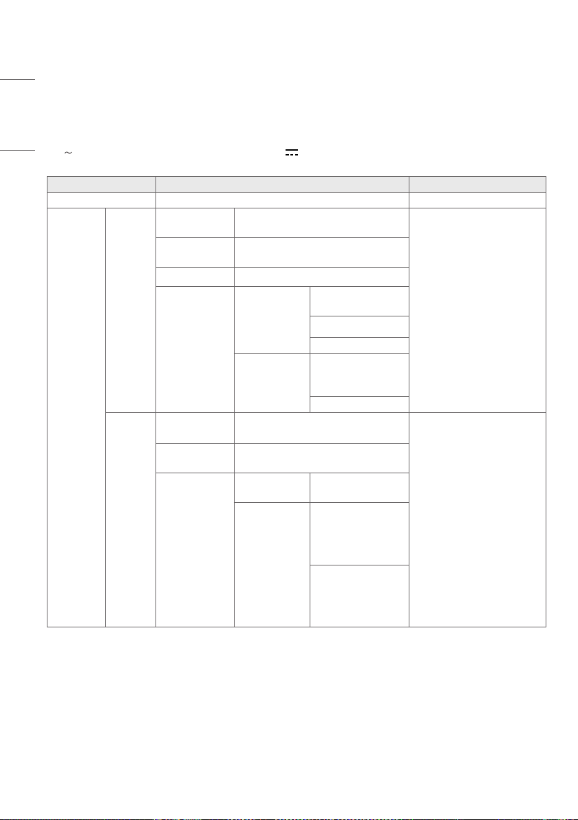
66
ENGLISH
PRODUCT SPECIFICATIONS
Without prior notice, all product information and specifications contained in this manual are subject to change to
improve the performance of the product.
The
symbol means alternating current, and the symbol means direct current.
Item Standard
Note
Power Supply 120 V~ 50/60 Hz
Input
HDMI
Maximum
Resolution
4096x2160@60Hz
• HDMI Cable Length
- 4096x216060Hz:3m
(9.8 ft)
- 4096x216030Hz:10m
(32.8 ft)
- 1920x108060Hz:15m
(49.2 ft)
• Refer to the supported
resolutions page for details
Recommend
Resolution
3840x2160@60Hz
HDCP Support HDCP2.2 & HDCP1.4
Color Format
& Depth
4K @
60/50Hz
RGB444 /
YCbCr444,8bits
YCbCr42212bits
YCbCr4208bits
4K @
30/25Hz
RGB444 /
YCbCr444,
8/10/12bits
YCbCr42212bits
SDI
(4 x BNC)
Maximum
Resolution
4096x2160@60Hz
(12G Input 4Ch each)
• SDI Cable Length (Cable type:
Belden1694A4.5C)
- 12G(2160p60):50m
(164.0 ft)
- 6G(2160p30):100m
(328.0 ft)
- 3G(1080p60):150m
(492.1 ft)
- HD(1080i60):250m
(820.2 ft)
- SD(525i59.94):300m
(984.2 ft)
• Refer to the supported
resolutions page for details
Recommend
Resolution
3840x2160@60Hz
Color Format &
Depth
4K @
60/50Hz
YCbCr42210bits
4K @
30/25Hz
RGB444 /
YCbCr444,
10/12bits
YCbCr422
10/12bits
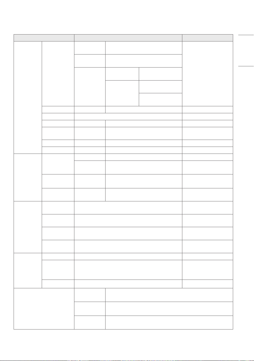
67
ENGLISH
Item Standard
Note
Input
SFP+
Maximum
Resolution
4096x2160@60Hz
* Supported SFP Module:
Embrionix SDI SFP
module
Recommend
Resolution
3840x2160@60Hz
Color Format &
Depth
4K @
60/50Hz
YCbCr42210bits
4K @
30/25Hz
RGB444 / YCbCr444,
10/12bits
YCbCr422
10/12bits
USB USB version USB2.0, set 1 (rear) Service (SW Update)
RS232C SW update and Calibration 4P,3.5mmPhoneJack
IR IR Receiver O Front TALLY part
Remote RJ45, 8pin GPI-7 Port
Remote Control via GPI
(RJ-45) Port
LAN RJ45, 8pin 100Base-T
REF Gen Lock Black Burst, Tri-Level
Output
Headphone
Output type Single Ended (L / R Stereo) 3P,3.5mmPhoneJack
Output level
Min / Typ. / Max
(0.627mV/0.98mV/1.334mV)
SDI
(4 x BNC)
Loop Through
SDI input format to SDI output
(up to 12G SDI)
Remote RJ45, 8pin GPI-7 Port
Remote Control via GPI
(RJ-45) Port
Use
Environment
Operating
Temperature
0~40°C(32°Fto104°F)
Operating
Humidity
10~80%
Storage
Temperature
-20~60°C(-4°Fto140°F)
Storage
Humidity
5~85%
Power
Consumption
Max 470W
Typ
300W(US)
380W(exceptUS)
OLED Light:
35 (US), 80 (other than
US)
Standby Mode 0.5W
Dimensions (Width x Height x
Depth) / Weight
Head
1446.3mmx853.8mmx56.5mm/31kg
(56.9inchesx33.6inchesx2.2inches/68.3lbs)
Stand
430mmx150.2mmx272.0mm/4kg
(16.9inchesx5.9inchesx10.7inches/8.8lbs)
Head + Stand
1446.3mmx896.5mmx272.0mm/35kg
(56.9inchesx35.2inchesx10.7inches/77.1lbs)
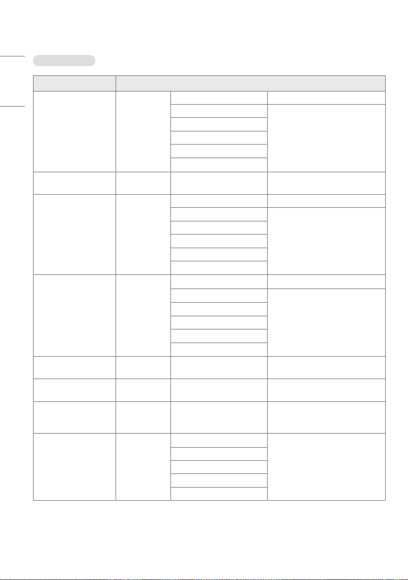
68
ENGLISH
SDI Support mode
Interfaces Signal Format
12G Single Link 4K
(ST 2082-10)
3840 x 2160
4096 x 2160
YCbCr4:2:210bit 47.95/48/50/59.94/60p
YCbCr4:2:212bit
23.98/24/25/29.97/30p
YCbCr4:4:410bit
YCbCr4:4:412bit
RGB4:4:410bit
RGB4:4:412bit
6G Single Link 4K
(ST 2081-10)
3840 x 2160
4096 x 2160
YCbCr4:2:210bit 23.98/24/25/29.97/30p
Quad Link 3G_A/B 4K
2-Sample Interleave
(ST 425-5)
3840 x 2160
4096 x 2160
YCbCr4:2:210bit 47.95/48/50/59.94/60p
YCbCr4:2:212bit
23.98/24/25/29.97/30p
YCbCr4:4:410bit
YCbCr4:4:412bit
RGB4:4:410bit
RGB4:4:412bit
Quad Link 3G_A/B 4K
Square
(ST 425-5)
3840 x 2160
4096 x 2160
YCbCr4:2:210bit 47.95/48/50/59.94/60p
YCbCr4:2:212bit
23.98/24/25/29.97/30p
YCbCr4:4:410bit
YCbCr4:4:412bit
RGB4:4:410bit
RGB4:4:412bit
Quad Link HD 4K
Square (ST 425-3)
3840 x 2160
4096 x 2160
YCbCr4:2:210bit 23.98/24/25/29.97/30p
1)
Dual Link 3G 4K
Square (ST 425-3)
3840 x 2160
4096 x 2160
YCbCr4:2:210bit
23.98/24/25/29.97/30p
(supported in SDI1 & SDI2 only)
Dual Link 3G_B 4K
2-Sample Interleave
(ST 425-3)
3840 x 2160
4096 x 2160
YCbCr4:2:210bit 23.98/24/25/29.97/30p
Dual Link 3G_A/B
(ST 425-3)
1920 x 1080
2048 x 1080
YCbCr4:2:212bit
47.95/48/50/59.94/60p
YCbCr4:4:410bit
YCbCr4:4:412bit
RGB4:4:410bit
RGB4:4:412bit
1) PsF (Progressive Segmented Frames) supported.
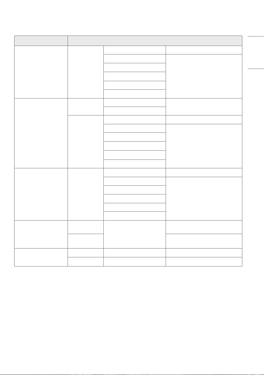
69
ENGLISH
Interfaces Signal Format
3G_B Dual Link
(ST 425-1)
1920 x 1080
2048 x 1080
YCbCr4:2:210bit 47.95/48/50/59.94/60p
YCbCr4:2:212bit
23.98/24/25/29.97/30p
1)
50/59.94/60i
YCbCr4:4:410bit
YCbCr4:4:412bit
RGB4:4:410bit
RGB4:4:412bit
3G_A Single Link
(ST 425-1)
1280 x 720
YCbCr4:4:410bit
23.98 / 24 / 25 / 29.97 / 30 / 50 / 59.94
/60p
RGB4:4:410bit
1920 x 1080
2048 x 1080
YCbCr4:2:210bit 47.95/48/50/59.94/60p
YCbCr4:2:212bit
23.98/24/25/29.97/30p
1)
50/59.94/60i
YCbCr4:4:410bit
YCbCr4:4:412bit
RGB4:4:410bit
RGB4:4:412bit
Dual Link HD
(ST 372)
1920 x 1080
2048 x 1080
YCbCr4:2:210bit 47.95/48/50/59.94/60p
YCbCr4:2:212bit
23.98/24/25/29.97/30p
1)
50/59.94/60i
YCbCr4:4:410bit
YCbCr4:4:412bit
RGB4:4:410bit
RGB4:4:412bit
HD Single Link
(ST 292)
1280 x 720
YCbCr4:2:210bit
23.98 / 24 / 25 / 29.97 / 30 / 50 / 59.94
/60p
1920 x 1080
2048 x 1080
23.98/24/25/29.97/30p
1)
50/59.94/60i
SD Single Link
(ST 259)
720 x 480 YCbCr4:2:210bit 59.94i
720 x 576 YCbCr4:2:210bit 50i
1) PsF (Progressive Segmented Frames) supported.
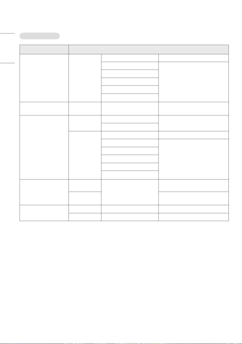
70
ENGLISH
SFP+ Support mode
Interfaces Signal Format
12G Single Link 4K
(ST 2082-10)
3840 x 2160
4096 x 2160
YCbCr4:2:210bit 47.95/48/50/59.94/60p
YCbCr4:2:212bit
23.98/24/25/29.97/30p
YCbCr4:4:410bit
YCbCr4:4:412bit
RGB4:4:410bit
RGB4:4:412bit
6G Single Link 4K
(ST 2081-10)
3840 x 2160
4096 x 2160
YCbCr4:2:210bit 23.98/24/25/29.97/30p
3G_A Single Link
(ST 425-1)
1280 x 720
YCbCr4:4:410bit
23.98 / 24 / 25 / 29.97 / 30 / 50 / 59.94
/60p
RGB4:4:410bit
1920 x 1080
2048 x 1080
YCbCr4:2:210bit 47.95/48/50/59.94/60p
YCbCr4:2:212bit
23.98/24/25/29.97/30p
1)
50/59.94/60i
YCbCr4:4:410bit
YCbCr4:4:412bit
RGB4:4:410bit
RGB4:4:412bit
HD Single Link
(ST 292)
1280 x 720
YCbCr4:2:210bit
23.98 / 24 / 25 / 29.97 / 30 / 50 / 59.94
/60p
1920 x 1080
2048 x 1080
23.98/24/25/29.97/30p
1)
50/59.94/60i
SD Single Link
(ST 259)
720 x 480 YCbCr4:2:210bit 59.94i
720 x 576 YCbCr4:2:210bit 50i
1) PsF (Progressive Segmented Frames) supported.
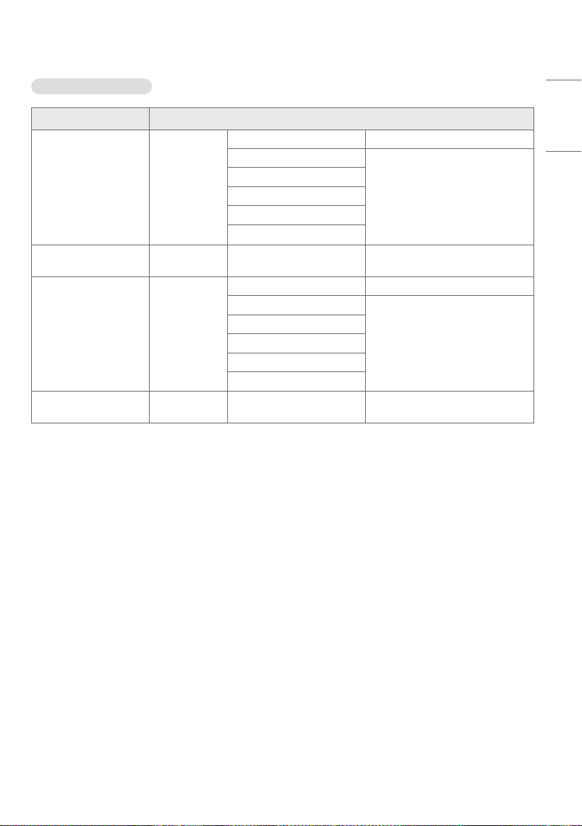
71
ENGLISH
Quad View Support mode
Interfaces Signal Format
12G Single Link 4K
(ST 2082-10)
3840 x 2160
4096 x 2160
YCbCr4:2:210bit 47.95/48/50/59.94/60p
YCbCr4:2:212bit
23.98/24/25/29.97/30p
YCbCr4:4:410bit
YCbCr4:4:412bit
RGB4:4:410bit
RGB4:4:412bit
6G Single Link 4K
(ST 2081-10)
3840 x 2160
4096 x 2160
YCbCr4:2:210bit 23.98/24/25/29.97/30p
3G_A Single Link
(ST 425-1)
1920 x 1080
2048 x 1080
YCbCr4:2:210bit 47.95/48/50/59.94/60p
YCbCr4:2:212bit
23.98/24/25/29.97/30p
YCbCr4:4:410bit
YCbCr4:4:412bit
RGB 4:4:4 10bit
RGB 4:4:4 12bit
HD Single Link
(ST 292)
1920 x 1080
2048 x 1080
YCbCr4:2:210bit 23.98/24/25/29.97/30p
* Support only at all same resolutions in each SDI inputs for Quad View.
* Quad Link only supports Progressive resolution.
72
ENGLISH
HDMI Support Mode
Signal Format
640 x 480
720 x 480
800 x 600
1024 x 768
1280 x 720
RGB4:4:48/10/12bit
60p
YCbCr4:4:48/10/12bit
YCbCr4:2:212bit
720 x 576
1280 x 720
RGB4:4:48/10/12bit
50pYCbCr4:4:48/10/12bit
YCbCr4:2:212bit
1920 x 1080
RGB4:4:48/10/12bit
24/25/30/50/60p
50/60i
YCbCr4:4:48/10/12bit
YCbCr4:2:212bit
2048 x 1080
RGB4:4:48/10/12bit
24/25/30/48/50/60p
50/60i
YCbCr4:4:48/10/12bit
YCbCr4:2:212bit
3840 x 2160
4096 x 2160
RGB4:4:48/10/12bit
24/25/30pYCbCr4:4:48/10/12bit
YCbCr4:2:212bit
RGB4:4:48bit
50/60p
YCbCr4:4:48bit
YCbCr4:2:212bit
YCbCr4:2:08bit

73
ENGLISH
LICENSES
Supported licenses may differ by model. For more information of the licenses, visit
www.lg.com
.
The terms HDMI, HDMI High-Definition Multimedia Interface, HDMI trade dress and the HDMI Logos are trademarks or
registered trademarks of HDMI Licensing Administrator, Inc.
Manufactured under license from Dolby Laboratories. Dolby, Dolby Vision, Dolby Vision IQ, Dolby Audio, Dolby Atmos,
and the double-D symbol are trademarks of Dolby Laboratories Licensing Corporation.
Open Source Software Notice Information
To obtain the source code that is contained in this product, under GPL, LGPL, MPL, and other open source licenses
that have the obligation to disclose source code, and to access all referred license terms, copyright notices and other
relevant documents, please visit
https://opensource.lge.com
.
LG Electronics will also provide open source code to you on CD-ROM for a charge covering the cost of performing such
distribution(suchasthecostofmedia,shipping,andhandling)uponemailrequesttoo
pensourc[email protected]om
.
Thisofferisvalidtoanyoneinreceiptofthisinformationforaperiodofthreeyearsafterourlastshipmentofthis
product.

Temporary noise is normal when powering ON or OFF
this device.
The model and serial number of the product are
located on the back and on one side of the product.
Record them below in case you ever need service.
MODEL
SERIAL NO.