Loading ...
Loading ...
Loading ...
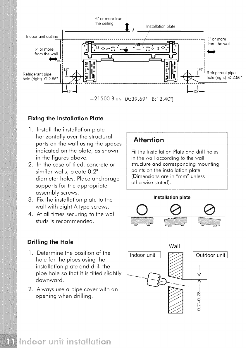
6" or more from
the ceiling I Installation plate
AI
I
Indoor unit outline I /
-""Tp" ....................................... _ ........................... _ { " or more
l, f - - _u _ _ from the wall
o (:3 o • • o / ° _ (:3oo • e
_i"ormore|, l'.ll':0 o_.=."=--" "';=:.._ 0 .11.'/ ,
from the wall|! I_ ;------',, -- , ,"--'4 ;='/ !_'_
_e e
Refrigerant pipe I= ! H', I]'llU21 I_llU21 fqt_ ! I Refrigerant pip e
hole (right) O 2.56" !i _--_'1 _ | | hole (right) O 2.56"
=21500 Bfus (A:39.69" B:12.40")
Fixing the Installation Plate
1. Install the installation plate
horizontally over the structural Attention
parts on the wall using the spaces
indicated on the plate, as shown Fitthe Installation Plate and drill holes
in the figures above, in the wall according to the wall
2. In the case of tiled, concrete or structureand corresponding mounting
similar walls, create 0.2" points on the installation plate
diameter holes. Place anchorage (Dimensionsare in "mm" unless
supports for the appropriate otherwisestated).
assembly screws.
3. Fix the installation plate to the Installation plate
walt with eight A type screws. O @ @
4. At all times securing to the wall
studs is recommended.
Drilling the Hole
Wall
1. Determine the position of the I Indoor unit [ Outdoor unit]
hole for the pipes using the
installation plate and drill the
pipe hole so that it is tilted slightly
downward.
2. Always use a pipe cover with an
opening when drilling.
Loading ...
Loading ...
Loading ...