COOKER HOOD
INSTRUCTION MANUAL
Read this manual carefully before operation
Pictures in this manual are for reference only, the product in kind prevail.
2 3 4
5 6 7 8
9 10 11
KWH-GLAV17SS-60
RECOMMENDATIONS AND SUGGESTIONS
The instructions for Use apply to several versions of this appliance. Accordingly, you
may find descriptions of individual features that do not apply to your specific appliance.
INSTALLATION
The manufacturer will not be held liable for any damages resulting from incorrect or
improper installation.
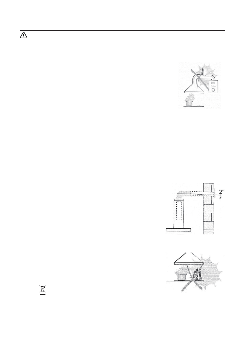
The minimum distance between the supporting surface for the cooking vessels on the
hob and the lowest part of the range hood. ( When the range hood is located above a
gas appliance, this distance shall be at least 65 cm. If the instructions for installation for
the gas hob specify a greater distance, this has to be taken into account. The distance of
65 cm can be reduced for:non-combustible parts of range hoods, and parts operating at
safety extra low voltage,Provided these parts do not give access to live parts if deformed ;)
Check that the mains voltage corresponds to that indicated on the rating plate fixed to
the hood.
For Class I appliances,check that the domestic power supply guarantees adequate earthing.
Connect the extractor to the exhaust flue through a pipe of minimum diameter 120mm.
The route of the flue must be as short as possible.
The air must not be discharged into a flue that is used for exhausting fumes from
appliances burning gas or other fuels.
If the extractor is used in conjunction with non-electrical appliances (e.g. gas burning
appliances),a sufficient degree of aeration must be guaranteed in the room in order to
prevent the backflow of exhaust gas. The kitchen must have an opening communicating
directly with the open air in order to guarantee the entry of clean air.
When the cooker hood is used in conjunction with appliances supplied with energy
other than electric, the negative pressure in the room must not exceed 0,04 mbar to
prevent fumes being drawn back into the room by the cooker hood.
If the supply cord is damaged, it must be replaced by the manufacturer, its service agent
or similarly qualified persons in order to avoid a hazard.
Regulations concerning the discharge of air have to be fulfilled.
USE
The cooker hood is only for home use, not suitable for barbecue, roast shop and other commercial purposes.
Never use the hood for purposes other than for which it has been designed.
Never leave high naked flames under the hood when it is in operation.
Adjust the flame intensity to direct it onto the bottom of the pan only, making sure that
it does not engulf the sides.
Deep fat fryers must be continuously monitored during use: overheated oil can
burst into flames.
Do not flame under the range hood; risk of fire.
This appliance can be used by children aged from 8 years and above and persons
with reduced physical, sensory or mental capabilities or lack of experience and
knowledge if they have been given supervision or instruction concerning use of the
appliance in a safe way and understand the hazards involved.
Children should be supervised to ensure that they do not play with the appliance.
Cleaning and user maintenance shall not be made by children without supervision.
“CAUTION: Accessible parts may become hot when used with cooking appliances”.
MAINTENANCE
The cooker hood and its filter should be cleaned regularly according to the instruction.
Switch off or unplug the appliance from the mains supply before carrying out any
maintenance work.
Clean and/or repace the Filters after the specified period(Fire hazard).
Clean the hood using a damp cloth and a neutral liquid detergent.
The appliance uses 4 hob elements at most.
The symbol is packaging indicates that this product may not be treated as household
waste. Instead it shall be handed over to the applicable collection point for the recycling of
electrical and electronic equipment. By ensuring this product is disposed of correctly, you
will help prevent potential negative consequences for the environment and human health,
which could otherwise be caused by inappropriate waste handling of this product. For more
detailed information about recycling of this product, please contact your local city office,
your household waste disposal service or the shop where you purchased the product.
2 3 4
5 6 7 8
9 10 11
1
Ref. Qty.
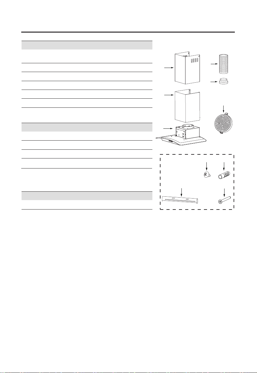
1
2.1
Blower,Filter.
Hood Body,complete with: Controls, Light,
1 Lower Decorative Chimney
2.2 1 Upper Decorative Chimney
3 1
4
Flange ( optional )
1 Exhaust Pipe
5 2 The Activated Charcoal filter ( optional )
1 Instruction Manual
COMPONENTS
Product Components
Qty. Documentation
6
7
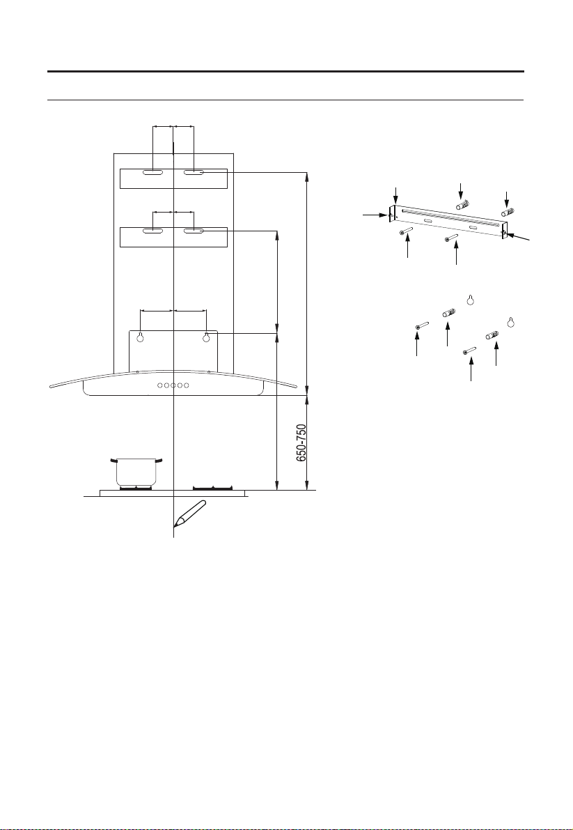
7 Screws 5 x 50
7 Wall Plugs
8
9
6
Screws 4.2 x 9.5
2
Chimney fixing bracket
Ref. Qty. Installation Components
4
2.2
3
2.1
5
1
8
7
9
6
2 3 4
5 6 7 8
9 10 11
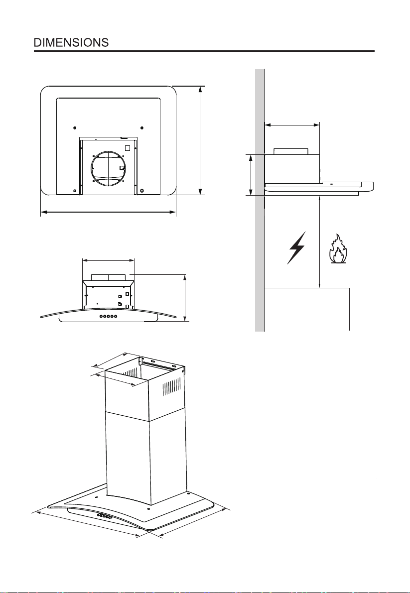
207
480
180
240
600
230
247
247
Min.
650mm
Min.
650mm
2 3 4
5 6 7 8
9 10 11
600
480
9
7
8
6
Vertical reference line
INSTALLATION
WALL DRILLING AND BRACKET FIXING
As a first step,proceed with the following drawings:
Mark Points:
A veritcal line up to the ceiling or up to the upper limit, at the center of the area in which the
hood is to be fitted.
The cooker hood should be placed 650-750 mm ( horizontal line A ) up from the cooking
plane for safe and a good effect.
A horizontal line B at a minimum 800-900 mm above the cooker top.
A horizontal line C at a 272 mm above the B.
A horizontal line D at 470-790 mm above the cooker hood.
Mark a point (1) on the horizontal line D, 60 mm to the vertical reference line.
Repeat this operation on the other side, checking that the three marks are leveled.
Mark a point (2) on the horizontal line C, 60 mm to the vertical reference line.
Repeat this operation on the other side, checking that the three marks are leveled.
Mark a point (3) on the horizontal line B, 80 mm to the vertical reference line.
Repeat this operation on the other side, checking that the three marks are leveled.
60 60
(1)
60 60
(2)
80 80
(3)
2 3 4
5 6 7 8
9 10 11
A
800-900
B
272
C
D
470-790
6
6
7
7
6
7
8
8
9
D
9
C
2XScrews
(ST5*50)
Fix lower decorative chimney
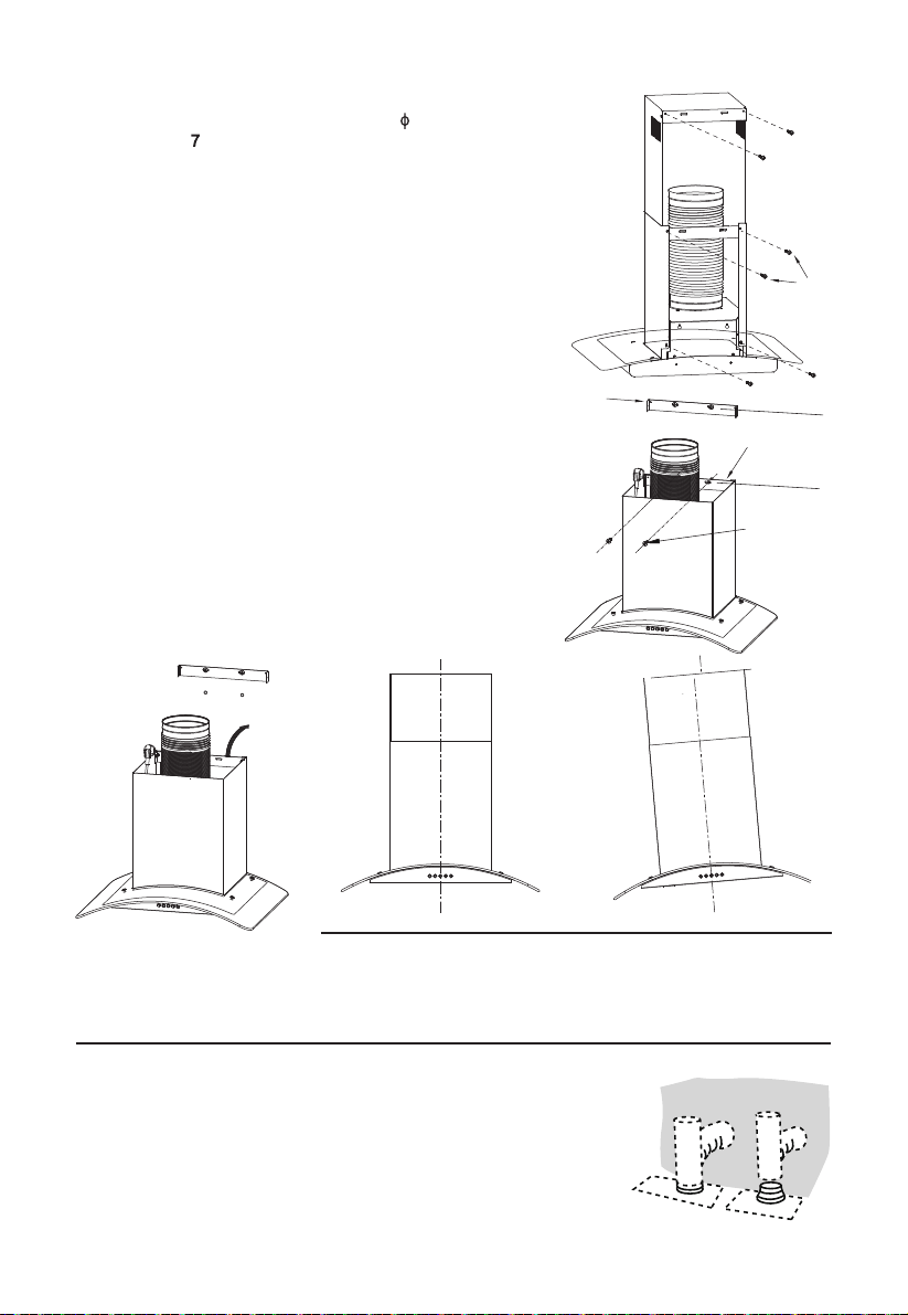
Right Wrong
CONNECTIONS
DUCTED VERSION AIR EXHAUST SYSTEM
When installing the ducted version, connect the hood to the chimney
using either a flexible or rigid pipe ɸ 150 or ɸ 120 mm, the choice of
which is left to the installer.
If to install a ɸ 120 mm air exhaust connection, insert the reducer
flange 3 on the hood body outlet.
Fix the pipe 4 in position using sufficient pipe clamps (not supplied).
Remove possible charcoal filters.
Chimney fixing bracket 9 with 2 screws 6 (ST5x50)
supplied with the hood at the horizontal line D.
Drill holes at the marked points with a 10 mm drill bit. Insert the
Wall Plugs into the holes.
Fix the Screws (5 x 50) bracket 6 with 2 screws
supplied with the hood at the horizontal line B.
Fix the brackets:
Fix the exhaust pipe on the hood body.
Connect chimney and hood body with 2 screws 8.
Connect chimney fixing bracket
9 and chimney with
2 screws 8.
2 3 4
5
6 7 8
9 10 11
To mount on the wall, drill two 10mm.
Insert two plastics wall plugs(supplied) into the holes.
Insert two screws (ST5*50) 6 into the upper two plastic wall
plugs, and tighten them leaving 3mm ,protruding from the Wall.
Mount the hood on the top screws, Insert the bottom
screws and fully tighten all the screws.
Hook the hood body

CHIMNEY ASSEMBLY
Upper Decorative Chimney
Insert the upper decorative chimney 2.2 into the lower decorative chimney 2.1 and drag it up
to the horizontal line D.
Connect upper decorative chimney 2.2 and chimney fixing bracket 9with 2 screws 8.
8
D
2.2
2.1
USE
Speed adjustment. (For some models)
ON/OFF LIGHTING SWITCH: Press on this switch to turn on
the lights, and press again to turn them off.
OFF MOTOR SWITCH: Press on this switch to stop the
motor operation.
SPEED SWITCH: Press on this switch, the motor runs at
LOW speed.
SPEED SWITCH: Press on this switch, the motor runs at
MEDIUM speed.
SPEED SWITCH: Press on this switch, the motor runs at
HIGH speed.
2 3 4
5 6
7 8
9 10 11
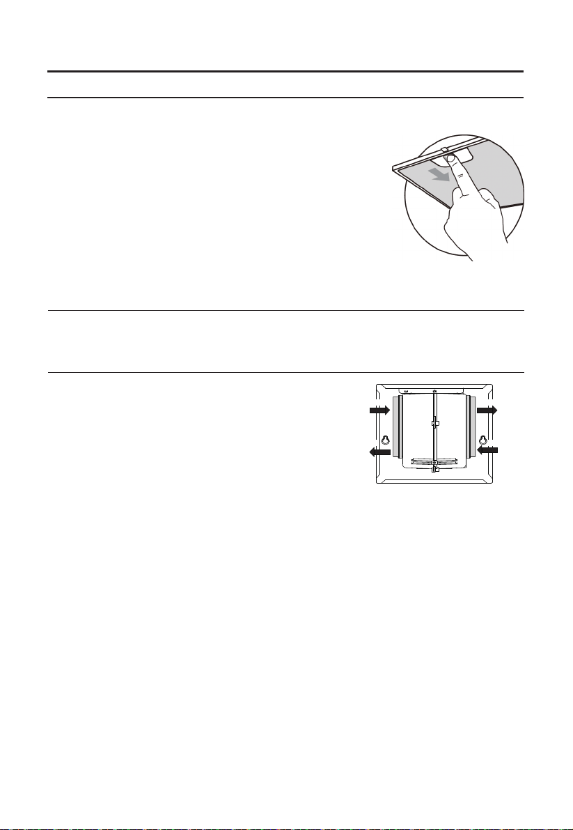
GREASE FILTERS
CLEANING METAL SELF-SUPPORTING GREASE FILTERS
The filters must be cleaned every 2 months of operation, or
more frequently for particularly heavy usage, and can be
washed in a dishwasher.
Pull the comfort panels to open them.
Remove the filters one by one pushing them towards the back
side of the hood unit and simultaneously pulling downwards.
Any kind of bending of the filters has to be avoided when washing
them. Before fitting them again into the hood make sure that they
are completely dry. (The color of the filter surface may change
throughout the time but this has no influence to the filter efficiency).
When fitting the filters into the hood pay attention that they are
mounted in correct position the handle facing outwards.
ACTIVATED CHARCOAL FILTER (RECIRCULATION VERSION)
These filters are not washable and cannot be regenerated, and must be replaced approximately
every 4 months of operation, or more frequently with heavy usage.
REPLACING THE ACTIVATED CHARCOAL FILTER
Remove the metal grease filters.
Remove the saturated activated charcoal filter.
Fit the new filters.
Replace the metal grease filters.
MAINTENANCE
UP
DOWN
UP
DOWN
8
LIGHTING
2 3 4
5 6 7 8
9
11
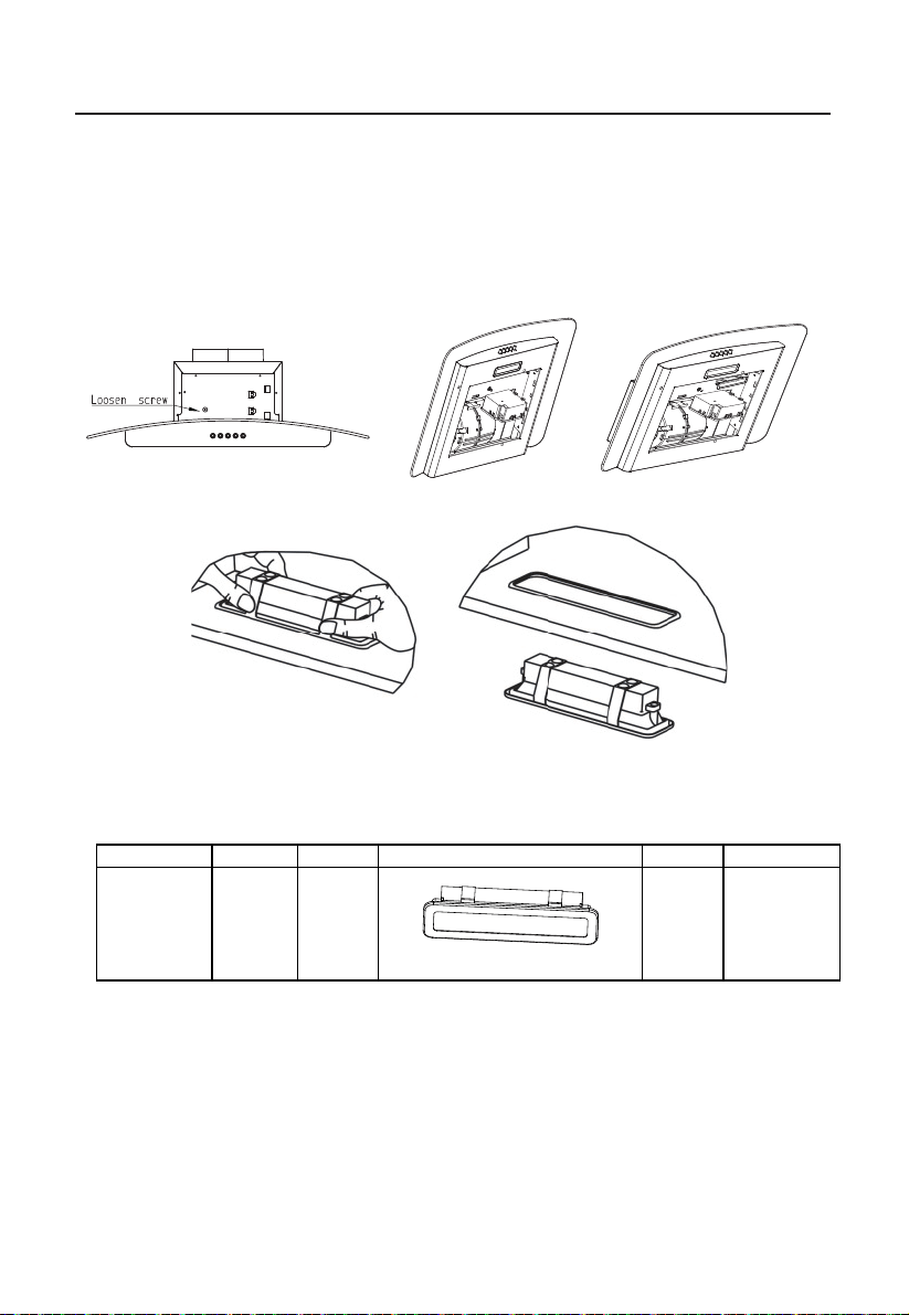
LIGHT REPLACEMENT
Replacing the light modules
Disconnect the power supply
Self-ballasted
LED modules
DB
S-1.5-
H-33.2/120
Max power Voltage Picture Lamp Cap ILCOS D code
1.5W 220-240V
Square/Diameter:33.2mmx120mm
/
9
Loosen Screw Take out the junction box Take out Led
DISPOSAL OF OLD ELECTRICAL APPLIANCES
The European directive 2012/19/EU on Waste Electrical and Electronic Equipment (WEEE), requires that old
household electrical appliances must not be disposed of in the normal unsorted municipal waste stream. Old
appliances must be collected separately in order to optimize the recovery and recycling of the materials they
contain, and reduce the impact on human health and the environment.
The crossed out “wheeled bin” symbol on the product reminds you of your obligation, that when you dispose of
the appliance, it must be separately collected.
Consumers should contact their local authority or retailer for information concerning the correct disposal of
their old appliance.
2 3 4
5 6 7 8
9
10 11
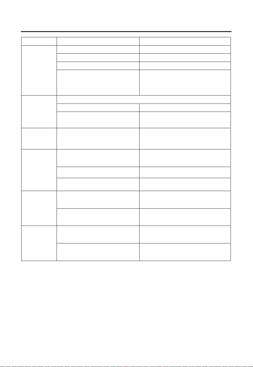
TROUBLE SHOOTING
Fault Cause Solution
Light on, but
motor does not
work
The blades are blocked.
The capacitor is damaged. Replace capacitor.
The motor is damaged. Replace motor.
Replace motor.
The internal wiring of motor is cut off/
disconnected. An unpleasant smell
may be produced.
Both light and
motor do not
work
Apart from the above mentioned, check the following:
Light damaged. Replace lights.
Power cord loose.
Connect the wires as the electric
diagram.
Oil leakage
Outlet and the air ventilation entrance
are not tightly sealed.
Take down the outlet and seal with glue.
Vibration
The blade, if damaged, can cause
vibrating.
Replace the blade.
The motor is not tightly fastened. Fasten the motor tightly.
The cooker hood is not tightly fixed. Fixed the cooker hood tightly.
Insufficient
suction
Readjust the distance.
The distance between the cooker
hood and the cooker top is too large.
Too much ventilation from open doors
or windows.
The
machine
Choose a new place to install the
appliance or close some doors / windows.
inclines
The fixing screws are not tight
enough.
Tighten the fixing screw and make it
horizontal.
The hanging screws are not tight
enough
Tighten the hanging screw and make it
horizontal.
Check the blades.
2 3 4
5 6 7 8
9 10
11

The manufacturer shall decline all responsibility if the foregoing
recommendations and instruction regarding installation, maintenance
and use are not observed and respected when using the cooker hood.
2 3 4
5 6 7 8
9 10 11
P/N:16173000A17448