INTENDED FOR DOMESTIC COOKING ONLY.
WARNING
TO REDUCE THE RISK OF FIRE, ELECTRIC SHOCK, OR INJURY TO PERSONS,
OBSERVE THE FOLLOWING:
1. Use this unit only in the manner intended by the manufacturer. If you have
questions, contact the manufacturer at the address or telephone number listed
in the warranty.
2. Before servicing or cleaning unit, switch power off at service panel and lock
the service disconnecting means to prevent power from being switched on
accidentally. When the service disconnecting means cannot be locked, securely
fasten a prominent warning device, such as a tag, to the service panel.
3. Installation work and electrical wiring must be done by a qualified person(s)
in accordance with all applicable codes and standards, including fire-rated
construction codes and standards.
4. Sufficient air is needed for proper combustion and exhausting of gases through
the flue (chimney) of fuel burning equipment to prevent backdrafting. Follow
the heating equipment manufacturer’s guideline and safety standards such as
those published by the National Fire Protection Association (NFPA), and the
American Society for Heating, Refrigeration and Air Conditioning Engineers
(ASHRAE), and the local code authorities.
5. When cutting or drilling into wall or ceiling, do not damage electrical wiring
and other hidden utilities.
6. To reduce the risk of fire or electric shock, do not use this range hood with
an additional speed control device.
7. Ducted fans must always be vented to the outdoors.
8. To reduce the risk of fire, use only metal ductwork.
9. Use with approved cord-connection kit only.
10. This unit must be grounded.
TO REDUCE THE RISK OF A RANGE TOP GREASE FIRE:
1. Never leave surface units unattended at high settings. Boilovers cause smok-
ing and greasy spillovers that may ignite. Heat oils slowly on low or medium
settings.
2. Always turn hood ON when cooking at high heat or when cooking flaming
foods.
3. Clean ventilating fans frequently. Grease should not be allowed to accumulate
on fan or filter.
4. Use proper pan size. Always use cookware appropriate for the size of the
surface element.
TO REDUCE THE RISK OF INJURY TO PERSONS IN THE EVENT OF A RANGE
TOP GREASE FIRE, OBSERVE THE FOLLOWING:*
1. SMOTHER FLAMES with a close-fitting lid, cookie sheet, or metal tray, then
turn off the burner. BE CAREFUL TO PREVENT BURNS. If the flames do not
go out immediately, EVACUATE AND CALL THE FIRE DEPARTMENT.
2. NEVER PICK UP A FLAMING PAN - You may be burned.
3. DO NOT USE WATER, including wet dishcloths or towels - a violent steam
explosion will result.
4. Use an extinguisher ONLY if:
A. You know you have a Class ABC extinguisher and you already know how
to operate it.
B. The fire is small and contained in the area where it started.
C. The fire department is being called.
D. You can fight the fire with your back to an exit.
* Based on “Kitchen Fire Safety Tips” published by NFPA.
CAUTION
1. For general ventilating use only. Do not use to exhaust hazardous or explosive
materials and vapors.
2. To avoid motor bearing damage and noisy and/or unbalanced impellers,
keep drywall spray, construction dust, etc. off power unit.
3. For best capture of cooking impurities, your range hood should be mounted
18-24” above the cooking surface.
4. Please read specification label on product for further information and
requirements.
ECONOMY RANGE HOOD
INSTALLATION
INSTRUCTIONS
PLANNING DUCTWORK INSTALLATION
This section for RL6300 Series hoods only.
For RL6200 Series hoods, skip this section and go on to “Prepare
the Hood”.
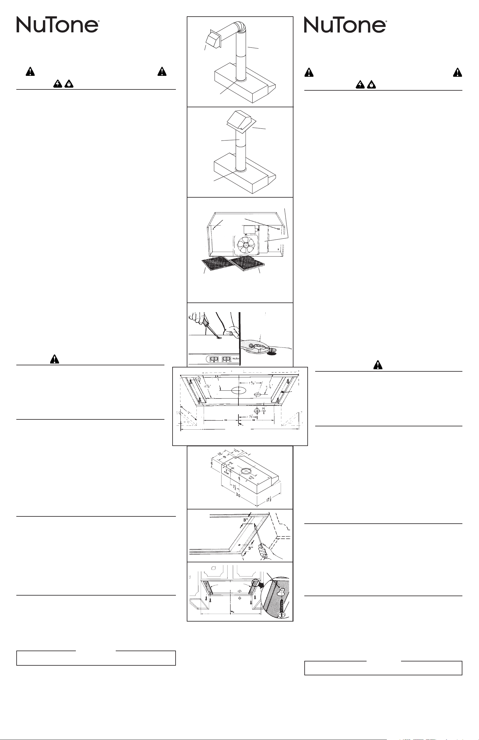
Begin planning ductwork by deciding where the duct will run between
the range hood and the outside. For best performance, use the shortest
possible duct run and a minimum number of elbows. There are several
choices shown - FIGS. 1 & 2 below.
FIG. 1
Sometimes when using a wall cap it is easier to duct vertically and then use
an elbow as shown.
Ducting between the ceiling joists (for multi-story installations) or through the
soffit space above the cabinets (where the soffit connects to an outside wall).
FIG. 2
Straight up through the roof using 7” round duct (for single story installations).
WALL CAP
MODEL 647
CASQUETE
DE PARED
MODELO
647
7” ROUND DUCT
MODEL 407
DUCTO REDONDO
DE 7 PLG.
MODELO 407
DAMPER
MODEL BP87Q
REGISTRO
DE TIRO
MODELO BP87Q
FIG. 1
FIG. 2
ROOF CAP
MODEL 634
CASQUETE
DE TECHO
MODELO 634
7” ROUND DUCT
MODEL 407
DUCTO REDONDO
DE 7 PLG.
MODELO 407
DAMPER
MODEL BP87Q
REGISTRO DE TIRO
MODELO BP87Q
KEYHOLE SLOTS
RANURAS
FIG. 3
FIG. 4
WIRING BOX COVER
CUBIERTA DE LA CAJA
DE CABLEADO
DUCTFREE FILTER
MICROTEK® SYSTEM I
(RL6200 SERIES ONLY)
FILTRO SIN DUCTOS
MICROTEK® SISTEMA I
(SOLAMENTE SERIE RL6200)
ALUMINUM FILTER
(RL6300 SERIES ONLY)
FILTRO DE ALUMINIO
(SOLAMENTE SERIE RL6300)
PREPARE THE HOOD
FIG. 3
1. Unpack hood and check contents. You should receive:
1 - Aluminum Filter (RL6300 Series only)
1 - Ductfree Microtek
®
System I Filter (RL6200 Series only)
2. Remove wiring box cover. Under cover find:
1 - Plastic Bag containing loose mounting hardware
FIG. 4
3. Remove top or rear electrical knockout.
4. (RL6300 Series only) Install Model BP87Q damper (purchase separately)
over opening in top of hood.
PREPARE THE INSTALLATION LOCATION
Omit STEP 1 if hood will be installed under cabinets with flush bottom.
FIGS. 5, 6 & 7
1. (For installation on recessed bottom cabinets only) Attach a wood filler strip
at each side of recessed area under cabinet. Use two 1” x 2” strips cut to
length. If recess is deeper than 1” use thicker strips. Attach strips with 1¼”
wood screws, 3” from each end of strip.
2. Measure and mark the following:
a.) Electrical wiring opening in wall or cabinet.
b.) Duct opening in wall or cabinet (RL6300 Series only).
WARNING
WHEN CUTTING OR DRILLING INTO WALL OR CABINET, BE CAREFUL
NOT TO CUT EXISTING ELECTRICAL WIRING.
3. Use 1¼” bit to drill opening for electric wiring.
4. Cut out duct opening in cabinet with saber saw or keyhole saw (RL6300
Series only).
5. Center hood in installation opening and trace keyhole slots onto wood filler strips
on cabinet bottom.
FIG. 8
6. Screw four #10 x 7/8 wood screws into exact center of narrow end of traced
keyhole slots. Allow 3/8” of screws to project, so that hood can be fitted into
place later.
KEYHOLE SLOT OUTLINE
CONTORNO DE LA RANURA
CENTER
LINE
LINEA DE
CENTROS
FIG. 8
FILLER STRIPS
PIEZAS DE MADERA
FIG. 7
FIG. 6
RL6300 SERIES
SERIE RL6300
HOOD WIDTH
ANCHO DEL EXTRACTOR
CENTER LINE
LINEA DE CENTROS
FILLER
STRIP
PIEZA
DE
MADE-
RA
** 10-15/16” FOR 24” RANGE HOOD
10-15/16 PLG. PARA EXTRACTOR DE 24 PLG.
** 13-15/16” FOR 30” RANGE HOOD
13-15/16 PLG. PARA EXTRACTOR DE 30 PLG.
6¼”
FIG. 5
PREVISTO PARA COCINAR DOMÉSTICO SOLAMENTE.
ADVERTENCIA
PARA REDUCIR EL RIESGO DE INCENDIO, CHOQUE ELECTRICO, O LESION A
PERSONAS, PROCURE LO SIGUIENTE:
1. Utilice esta unidad sólo en la manera prescrita por el fabricante. Si tiene usted
alguna pregunta, comuníquese con el fabricante a la dirección o el teléfono
indicados en la garantía.
2. Antes de limpiar o de poner en servicio la unidad, apague el interruptor en el
panel de servicio, y asegure el panel de servicio para evitar que se encienda
accidentalmente. Cuando el dispositivo para desconectar el servicio eléctrico
no puede ser cerrado con algún tipo de traba, sujete fuertemente al panel de
servicio, una etiqueta de advertencia prominente.
3. Todo trabajo de instalación y cableado eléctrico debe ser realizado por personal
calificado y de acuerdo con todos los códigos y normas pertinentes, incluyendo
los códigos y normas relacionados con construcción clasificada para incendio.
4. Aire suficiente es necesario para facilitar la combustión adecuada y la salida
apropiada de gases por la chimenea de la unidad y para evitar corrientes de
aire invertidas. Siga las instrucciones y medidas de seguridad del fabricante
del equipo y de las sociedades profesionales de equipos de calentadores y
los reglamentos de seguridad locales.
5. A cortar o perforar la pared o el techo, no dañe el cableado eléctrico u otros
servicios públicos ocultos a la vista.
6. Para reducir el riesgo de incendio o de descarga eléctrica, no utilice este
ventilador con ningún dispositivo de una control de velocidad de estado sólido
adicional.
7. Los abanicos con ducto deberán siempre tener una salida hacia el exterior.
8. Para reducir el riesgo de incendio, use sólo ductos de metal.
9. Uso con el kit aprobado del la conexión de la cuerda solamente.
10. Esta unidad se debe instalar con tierra efectiva.
PARA REDUCIR EL RIESGO DE INCENDIO DEBIDO A GRASA ACUMULADA EN
LAS HORNILLAS:
1. Nunca deje sin atender las unidades de superficie cuando tengan ajustes altos.
Los reboses pueden provocar humo y derrames grasosos que se pueden
incendiar. Caliente lentamente el aceite en un ajuste bajo o medio.
2. Siempre ENCIENDA la campana cuando cocine con alta temperatura o cuando
cocine alimentos que se puedan incendiar.
3. Limpie con frecuencia los ventiladores. No debe permitir que la grasa se
acumule en el ventilador ni en el filtro.
4. Utilice un sartén de tamaño adecuado. Siempre utilice el utensilio adecuado
al tamaño del elemento de superficie.
PARA REDUCIR EL RIESGO DE LESION A PERSONAS RESULTADO DE UN IN-
CENDIO DEBIDO A GRASA ACUMULADA EN LAS HORNILLAS, PROCURE LO
SIGUIENTE:*
1. AHOGUE LAS LLAMAS con una tapa ajustada o charola de metal, después
apague la hornilla. TENGA CUIDADO A FIN DE EVITAR QUEMADURAS. Si las
llamas no se apagan de inmediato, EVACUE Y AVISE A LOS BOMBEROS.
2. NO LEVANTE NUNCA UNA SARTEN QUE ESTE EN LLAMAS - Usted se podrá
quemar.
3. NO UTILICE AGUA, incluyendo toallas de cocina mojadas - puede resultar una
explosión de vapor violenta.
4. Utilice un extinguidor SOLAMENTE si:
A. Usted sabe que tiene un extinguidor de clase ABC y lo sabe utilizar.
B. El incendio es pequeño y contenido dentro del área donde se inició.
C. Los bomberos han sido avisados.
D. Usted puede combatir el incendio con una salida a su espalda.
* Basado en las recomendaciones para “Seguridad en la Cocina” publicadas
por la NFPA de los EEUU.
INSTRUCCIONES DE
INSTALACION DE LOS
EXTRACTORES TIPO ECONOMICO
LEA Y CONSERVE ESTAS INSTRUCCIONES
READ AND SAVE THESE INSTRUCTIONS
Register this product at
www.broan.com/register. For
Warranty Statement, or to order
Service Parts: go to www.broan.com
and type the Model in the “Model
Search” field at the top of the page.
Broan, 926 W. State Street,
Hartford, WI 53027 800-637-1453
Registre este producto en www.
broan.com/register. Para Declaración
de garantía, o para pedir piezas de
servicio: vaya a www.broan.com y
escriba el modelo en el campo “Model
Search” en la parte superior de la
página. Broan, 926 W. State Street,
Hartford, WI 53027 800-637-1453
PRECAUCION
1. Solamente para uso general de ventilación. No utilice para descargar
materiales o vapores riesgosos o explosivos.
2. Para evitar daños al motor y evitar que las navajas del abanico emitan mucho
ruido o estén fuera de balance, mantenga el motor libre de pelusa, polvo, etc.
3. Para obtener mejores resultados en la captura de los vapores de la estufa, el
extractor debe montarse a entre 18 y 24 plg. sobre las hornillas de la estufa.
4. Por favor lea la etiqueta con las especificaciones del equipo para otros
requisitos y mayor información.
PLANEANDO LA INSTALACION DE LOS DUCTOS
Esta sección es sólo para extractores Serie RL6300.
Si su extractor es Serie RL6200, sáltese esta sección y continúe en la sección
de “PREPARANDO EL EXTRACTOR”.
Inicie el plan para instalar los ductos decidiendo por dónde va a pasar el ducto
entre el extractor y la pared. Para obtener un mejor funcionamiento, escoja
la salida más directa posible para el ducto, y el menor número de codos. Existen
diferentes opciones que se muestran en las FIGURAS A y B enseguida.
FIG. 1
Algunas veces es más sencillo usar un casquete de pared colocándolo verticalmente
y usando un codo como el mostrado.
Colocándolo entre las vigas del techo (para las instalaciones múltiples) o a través
de un espacio de plafón sobre los gabinetes (en donde el plafón se conecta a una
pared externa).
FIG. 2
Utilizando un ducto circular de 7 plg. en posición vertical (para instalaciones indi-
viduales ).
PREPARANDO EL EXTRACTOR
FIG. 3
1. Desempaque el extractor y revise el contenido de la caja. Usted debe
encontrar:
1 - Filtro de aluminio (solamente Serie RL6300)
1 - Sistema de filtro Ductfree Microtek
®
System
2. Retire la cubierta de la caja de cableado. Bajo la cubierta encontrará:
1 - Bolsa de plástico que contiene las piezas necesarias para la instalación
FIG. 4
3. Retire el tapón eléctrico trasero superior.
4. (Solamente Serie RL6300) Instale el regulador Modelo BP87Q (comprado por
separado) sobre la abertura en la parte superior del extractor.
ACONDICIONE EL LUGAR DE LA INSTALACION
Si el extractor va a ser instalado bajo gabinetes con suelo nivelado, omita el PASO 1.
FIGS. 5, 6 y 7
1. (Solamente para la instalación en los gabinetes con espacios libres) Coloque
una pieza de madera en cada uno de los lados para rellenar el área libre debajo
del gabinete. Utilice dos tiras de madera de 1 plg. x 2 plg. de longitud. Si el
área libre tiene más de 1 plg. de profundidad, utilice piezas de madera más
gruesas. Ajuste las piezas con tornillos para madera de 1¼ plg., a 3 plg. de
los extremos.
2. Mida y marque lo siguiente:
a.) La abertura del cableado eléctrico en la pared o el gabinete.
b.) La abertura para el ducto en la pared o el
gabinete (solamente Serie RL6300).
ADVERTENCIA
CUANDO ESTE CORTANDO O PERFORANDO LA PARED O EL GABINETE,
ASEGURESE DE NO CORTAR EL CABLEADO ELECTRICO EXISTENTE.
3. Utilice un taladro de 1¼ plg. para hacer la abertura para el cableado eléctrico.
4. Haga un corte en el gabinete, para la entrada del ducto, con un serrucho o una
sierra de punta o de calador (solamente Serie RL6300).
5. Centre el extractor en la entrada de la instalación y marque las ranuras en las
piezas de madera que rellenan el espacio libre en la parte inferior del gabinete.
FIG. 8
6. Ajuste 4 tornillos para madera #10 x 7/8 justo en el centro del extremo angosto
de las ranuras marcadas. Permita que los tornillos salgan 3/8 plg. para que el
extractor pueda ser colocado en su lugar.
INSTALL THE DUCTWORK
(This section for RL6300 Series hoods only. For RL6200 Series hoods, skip this
section and go on to “Install Range Hood”.)
NOTE
These instructions will follow plans made on Page 2. Start at the exterior
and run ductwork back to the range hood.
For best possible performance, use the shortest possible duct run and a
minimum number of elbows. Do not vent a range hood into an attic space. A
buildup of grease in the attic could become a re hazard.
Use only metal ductwork. DO NOT USE PLASTIC DUCT. Assemble duct run
securely so that in case of a grease re on the range, the re will be contained
inside metal ductwork.
Tape all duct connections.
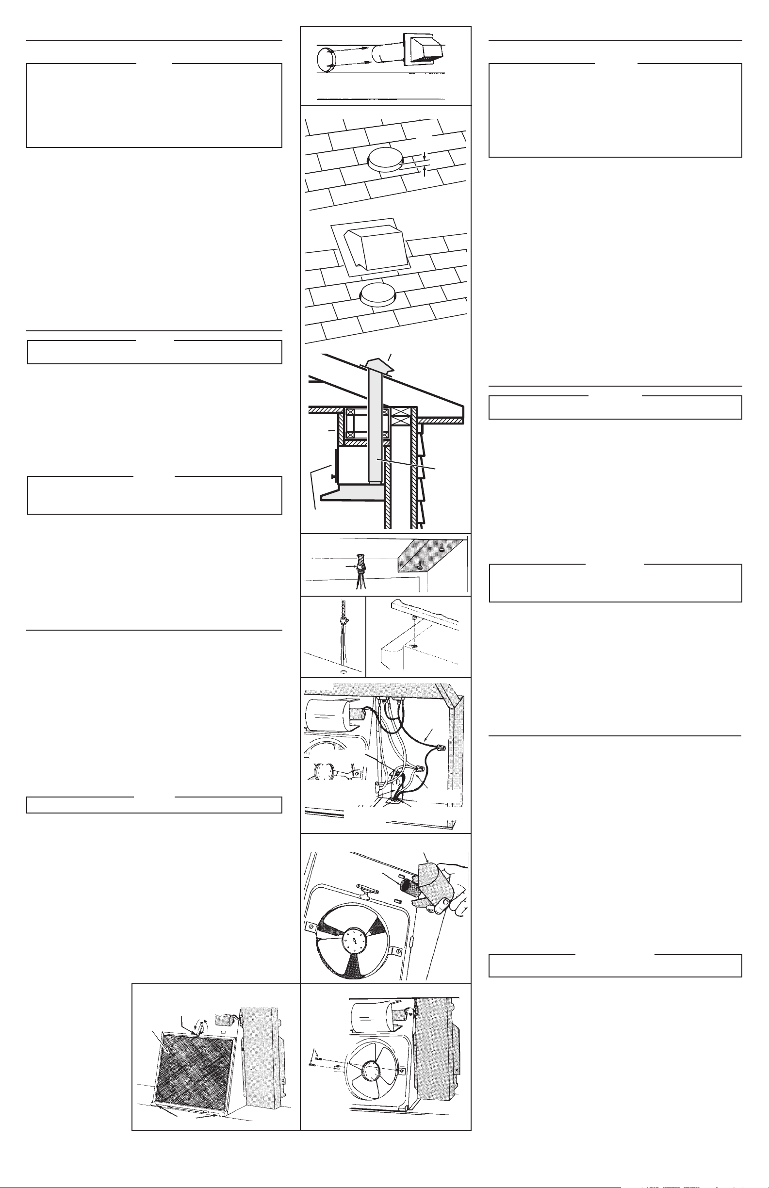
1. Follow appropriate directions for type of duct run you install.
FIG. 9
Wall Cap Discharge: Use saber saw or keyhole saw to cut hole slightly larger
than duct size used so that duct will line up easily with damper/duct conector
on hood. Install casing strips if cap will be installed on siding. Attach required
amount of duct to wall cap and run duct back to hood. Fasten cap to wall and
caulk well.
FIG. 10
Roof Cap Discharge: Cut a hole in roof slightly larger than duct size being used.
Run ductwork down to hood location. Leave 3/4” of duct projecting above roof
surface on high side.
Trim duct parallel to roof pitch and seal all around duct with roof cement.
Carefully trim shingles and slide back of roof sheet under shingles. Nail roof
sheet to roof under shingles at top two corners and two sides. Nail sheet directly
to roof in four places at bottom.
Using roof cement, seal all nail heads and shingles which were cut or lifted.
Do not seal bottom edge of roof sheet.
7” ROUND
DUCT
DUCTO
REDONDO
DE 7 PLG.
SOFFIT
PLAFON
FIG. 9
FIG. 10
3/4”
3/4 PLG.
ROOF CAP
CASQUETE DE
TECHO
CABINET
GABINETE
INSTALACION DEL DUCTO
(Esta sección es solamente para los extractores serie RL6300. Serie RL6200
pueden saltarse ésta sección y continuar en la “INSTALACION DEL EXTRACTOR”. )
NOTA
Estas instrucciones seguirán los planes descritos en la pág 2. Comience
a trabajar del exterior al interior para conectar el ducto con el extractor.
Para obtener un mejor funcionamiento del extractor, procure que la salida
del ducto sea la más directa y que tenga el menor número de codos.
No permita que la salida del extractor quede en un desván. Si se forma
una capa de grasa en el desván puede ser peligroso y causar un incendio.
Utilice solamente ductos de metal. NO USE DUCTOS DE PLASTICO. Ensamble
el ducto rmemente para que en caso de que se prenda debido a la grasa,
el fuego se contenga dentro del ducto de metal. Coloque cinta de aislar en
todas las conexiones del ducto.
1. Siga las incicaciones adecuadas para el tipo de ducto que vaya a instalar.
FIG. 9
Salida del casquete de pared: Utilice un serrucho o una sierra de calador para
cortar un orificio un poco más grande que el tamaño del ducto, para poder aco-
modar facilmente el ducto con el conector del ducto/regulador en el extractor. Si
el casquete se va a instalar en un lado, instale las tiras del marco. Fije la cantidad
requerida del ducto en el casquete de pared y acomode el ducto en el extractor.
Ajuste el casquete a la pared. Fijelo con un martillo. (Si la pared es de
concreto u otro material, ejecute las operaciones necesarias para obtener los
mismos resultados.)
FIG. 10
Salida del casquete por el techo: Haga un orificio en el techo, ligeramente más
grande que la circunferencia del ducto que se está usando. Coloque el ducto
debajo del lugar donde va el extractor. Deje que 3/4 plg. del ducto sobresalgan
por encima de la superficie en el lado alto del techo.
Ajuste el ducto paralelamente con la inclinación del techo y selle alrededor del
tubo con cemento para techos o tejados.
Empareje las tejas con cuidado y deslice la placa del tejado que está debajo de
las tejas. Clave la placa del tejado a la parte de techo que está bajo las tejas en
las dos esquinas y los dos lados superiores. Clave la placa directamente al tejado
en cuatro extremos en la parte inferior.
Utilizando cemento para tejado, selle todas las cabezas de los clavos y las tejas que
fueron cortadas o levantadas. No selle el extremo inferior de la placa del tejado.
CONNECTOR
CONECTOR
SOCKET
ENCHUFE
LIGHT LENS
LAMPARA
FIG. 12
FIG. 13
FIG. 14
BLACK WIRES
CABLES NEGROS
GREEN GROUND SCREW
TORNILLO DE TIERRA VERDE
GROUND WIRE (BARE OR
GREEN WIRE)
CABLE DE TIERRA (CABLE
DESCUBIERTO O VERDE)
GROUNDING BRACKET
MENSULAS DE TIERRA
STAR LOCKNUT
TUERCA DE FIJACION
DE ESTRELLA
WHITE WIRES
CABLES BLANCOS
FIG. 11
INSTALL RANGE HOOD
WARNING
TURN OFF THE PROPER CIRCUIT AT THE SERVICE ENTRANCE BEFORE WIR-
ING THIS RANGE HOOD.
FIG. 11
1. Run electric wiring through hole drilled in wall or cabinet. Split wiring for 6” and
install proper connector for type of wire used.
FIG. 12
2. Position hood so that:
a.) Wiring is routed through knockout opening.
b.) Large part of keyhole slots fit over hood mounting screws.
c.) Damper/duct connector slides into ductwork. (RL6300 Series only)
3. Adjust hood so that hood front is flush with cabinet frame.
4. Tighten hood mounting screws firmly.
5. Fasten wiring to hood with proper electrical connector for type of wire being used.
WARNING
ALL ELECTRICAL CONNECTIONS MUST BE IN ACCORDANCE WITH LOCAL
CODES, ORDINANCES, OR NATIONAL ELECTRICAL CODE. IF YOU ARE UNFA-
MILIAR WITH METHODS OF INSTALLING ELECTRICAL WIRING, SECURE THE
SERVICES OF A QUALIFIED ELECTRICIAN.
FIG. 13
6. Strip 1/2” of insulation from wires. Connect white to white, black to black, and
green to prepared hole with green ground screw provided.
7. Replace wiring box cover and screw. Make sure that all wiring is safely contained
inside.
FIG. 14
8. Install light (75 Watt maximum). For easier installation, squeeze plastic lens and
remove it from hood. Remember to reinstall lens.
9. Turn on power and check operation of fan and light. Make sure that damper
operates freely.
INSTALACION DEL EXTRACTOR
ADVERTENCIA
DESCONECTE EL CIRCUITO EN LA ENTRADA DE SERVICIO ANTES DE CONEC-
TAR EL CABLEADO DEL EXTRACTOR.
FIG. 11
1. Pase el cableado eléctrico a través de un orificio en la pared o el gabinete. Separe
el cableado a 6 plg. e instale el conector apropiado para el tipo de cable usado.
FIG. 12
2. Coloque el extractor para que:
a.) El cableado salga por la salida del tapón.
(Serie MX solamente: Utilice el ojal reforzado provisto en bolso de las piezas.)
b.) Las partes grandes de las ranuras se ajustan en los tornillos de la montura
del extractor.
c.) El conector del ducto/regulador se deslice dentro del ducto. (SOLAMENTE
para serie RL6300)
3. Ajuste el extractor para que la parte del frente se nivele con el gabinete.
4. Ajuste los tornillos de la montura del extractor con firmeza.
5. Ajuste el cableado al extractor con el conector eléctrico adecuado para el tipo
de cable que se va a utilizar.
ADVERTENCIA
TODAS LAS CONEXIONES ELECTRICAS DEBEN SER REALIZADAS DE ACUERDO CON
LOS CODI-GOS LOCALES, REGLAMENTOS Y CODIGOS ELECTRICOS NACIONALES.
SI NO ESTA FAMILIAIZADO CON LOS METODOS DE INSTALACION DE CABLEADO
ELECTRICO, CONTRATE LOS SERVICIOS DE UN ELECTRICISTA CALIFICADO.
FIG. 13
6. Pele 1/2 plg. de aislante de los cables. Conecte los cables, blanco con blanco,
negro con negro y el verde con el orificio hecho con el tornillo de tierra verde,
proporcionado en la bolsa.
7. Coloque de nuevo la tapa de la caja del cableado y el tornillo. Asegúrese de que
todo el cableado quede bien contenido en el interior.
FIG. 14
8. Instale el foco (máximo 75 watts). Para lograr una instalación más sencilla,
presione los protectores plásticos y retírelos del extractor. Recuerde reinstalar
los protectores.
9. Conecte la corriente para revisar la operación del abanico y la luz. Asegúrese de
que el regulador funcione con libertad.
USE AND CARE
SWITCHES
The fan and light are each controlled by a rocker switch. The light switch has two posi-
tions, “ON” and “OFF”. The fan switch has three positions - “HIGH”, “LOW” and “OFF”. (
“OFF” is the middle position.)
FILTERS - FIG. 15
RL6300 Series Only:
Remove aluminum filter by turning filter retainer to one side. Filter should be washed
once a month in a hot detergent solution. Aluminum filters are dishwasher safe. When
installing filter, make sure that filter slides under retaining tabs on back of fan housing.
Turn filter retainer so that arrows on retainer point toward front and back of hood.
RL6200 Series Only:
The hood is equipped with a ductfree filter. Remove filter by turning filter retainer to one
side. The ductfree filter is not washable, and will last up to twelve months with normal use.
Replace the filter when colored side becomes noticeably dirty or discolored.
When installing filter, make sure that filter slides under retaining tabs on back of fan
housing. MAKE SURE THAT COLORED SIDE OF FILTER IS NEXT TO FAN WHEN
FILTER IS INSTALLED. Turn filter retainer so that arrows on retainer point toward front
and back of hood.
WARNING
ALWAYS DISCONNECT ELECTRIC POWER BEFORE SERVICING RANGE HOOD.
FAN ASSEMBLY - FIG. 16
Remove filter. Remove two screws holding motor bracket to range hood, and unplug
fan assembly. Be careful not to allow fan assembly to drop when screws are removed.
CLEANING
Clean your hood with a mild detergent suitable for painted surfaces. DO NOT USE
ABRASIVE CLOTH, STEEL WOOL PADS OR SCOURING POWDERS.
Fan assembly may be vacuumed. Fan assembly is permanently lubricated, and never
needs oiling.
USO Y CUIDADOS
LOS INTERRUPTORES
El abanico y el foco están controlados individualmente por un interruptor balancín. El
interruptor del foco tiene dos posiciones, ENCENDIDO (“ON”) y APAGADO (“OFF”).
El interruptor del abanico tiene tres posiciones - ALTA (“HIGH”), BAJA (“LOW”) y
APAGADO (“OFF”). (El interruptor para APAGADO está en la posición de en medio.)
LOS FILTROS - FIG. 15
Solamente serie RL6300:
Retire el filtro de aluminio girando el contenedor del filtro hacia un lado. El filtro debe
lavarse una vez al mes en una solución jabonosa caliente. Los filtros de aluminio se
pueden lavar en la lavadora de platos. Cuando instale un filtro, asegúrese de que el
filtro se deslice debajo de los apéndices en la parte trasera del compartimiento del
abanico. Gire el contenedor del filtro para que las flechas del contenedor apunten
hacia el frente y la parte trasera del extractor.
Solamente serie RL6200:
El extractor está equipado con un filtro sin ducto. Retire el filtro girando el contenedor
del filtro hacia un lado. (FIG. 13) El filtro sin ducto no se puede lavar, y durará hasta
doce meses con un uso normal. Coloque de nuevo el filtro cuando el lado de color
se torne sucio o se decolore.
Cuando instale un filtro, asegúrese de que el filtro se deslice por debajo de los
apéndices en la parte trasera del compartimiento del abanico. ASEGURESE DE QUE
EL LADO COLOREADO DEL FILTRO QUEDE ENSEGUIDA DEL ABANICO, CUANDO
EL FILTRO SEA INSTALADO. Gire el contenedor del filtro para que las flechas de el
contenedor apunten hacia el frente y la parte trasera del extractor.
ADVERTENCIA
DESCONECTE SIEMPRE EL CABLE DE ELEC-TRICIDAD ANTES DE DARLE
SERVICIO DE MANTENIMIENTO AL EXTRACTOR.
EL ENSAMBLE DEL ABANICO - FIG. 16
Retire el filtro. Retire los dos tornillos que sostienen el motor en el extractor, y de-
sconecte el ensamble del abanico. Asegúrese de no permitir que el abanico se caiga
cuando retire los tornillos.
LA LIMPIEZA
Limpie su extractor con un detergente suave que sea adecuado para superficies
pintadas. NO UTILICE PIEZAS DE TELA ABRASIVAS, FIBRAS O DETERGENTE.
El abanico puede ser aspirado. El ensamble del abanico está lubricado permanenta-
mente y no necesita que se le agregue aceite.
FIG. 16
SCREWS
TORNILLOS
FILTER RETAINER
SOPORTE DEL FILTRO
TABS
APENDICES
FIG. 15
FILTER
FILTRO
99043827G