Mobile air-conditioner
-
1
-
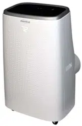
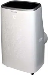
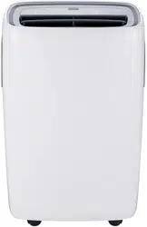
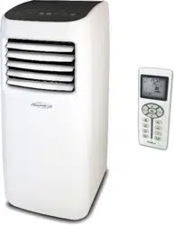
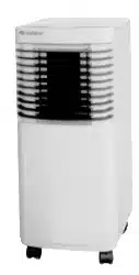
figure 1-1
KY-20/(2001)
KY-20N/(2001)
KY-20N/A
KY-20N/B
KY-20U/11156
KY-20U/A-11156
KY-20U/B-11156
GP8-12L
GP8-22L
CE STANDARD
1Ph 220-230V 50Hz R22
CE STANDARD
1Ph 220-230V 50Hz R407C
UL STANDARD
1Ph 115V 60Hz R22
1Ph 115V 60Hz R22
1Ph 220V 60Hz R22
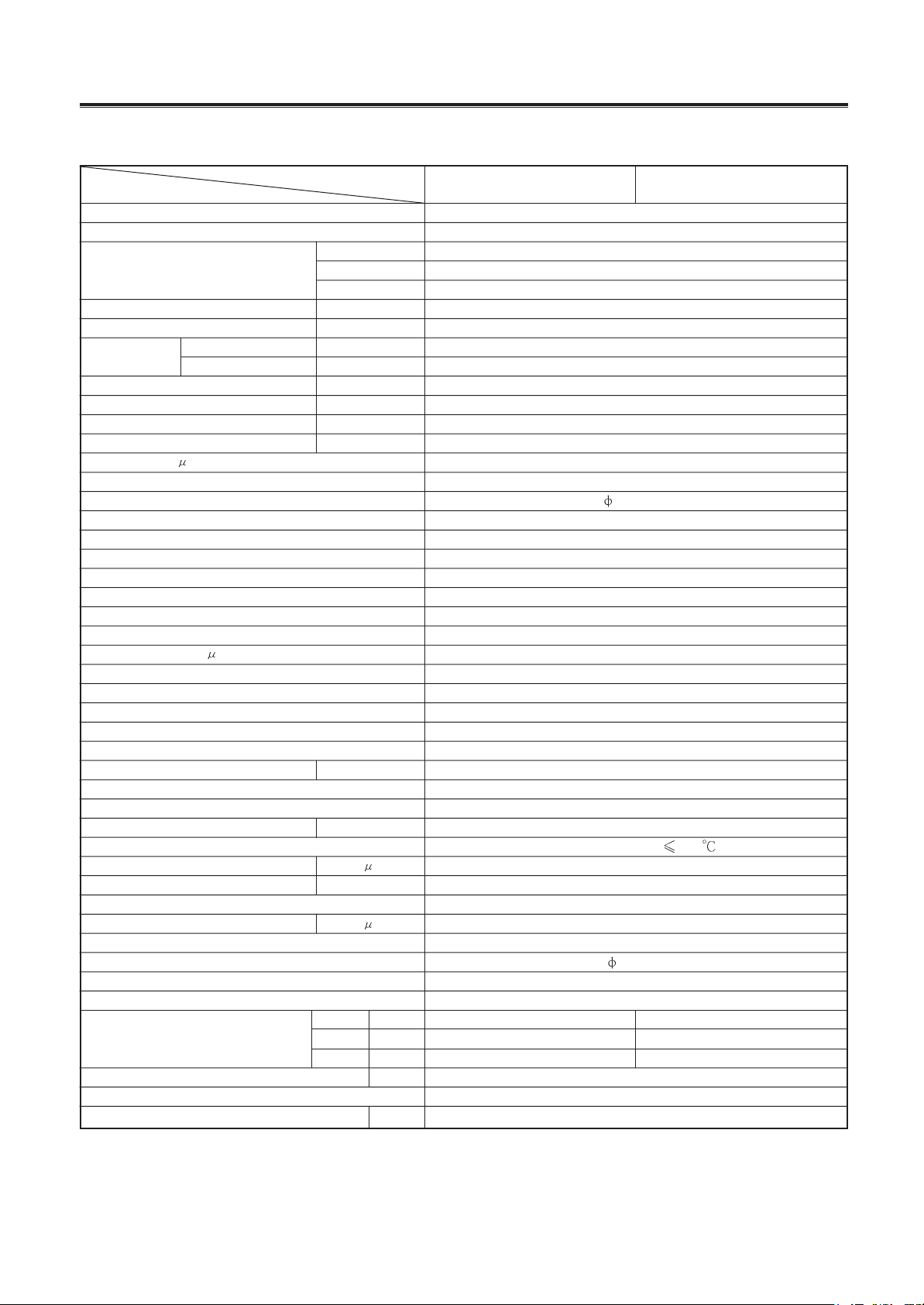
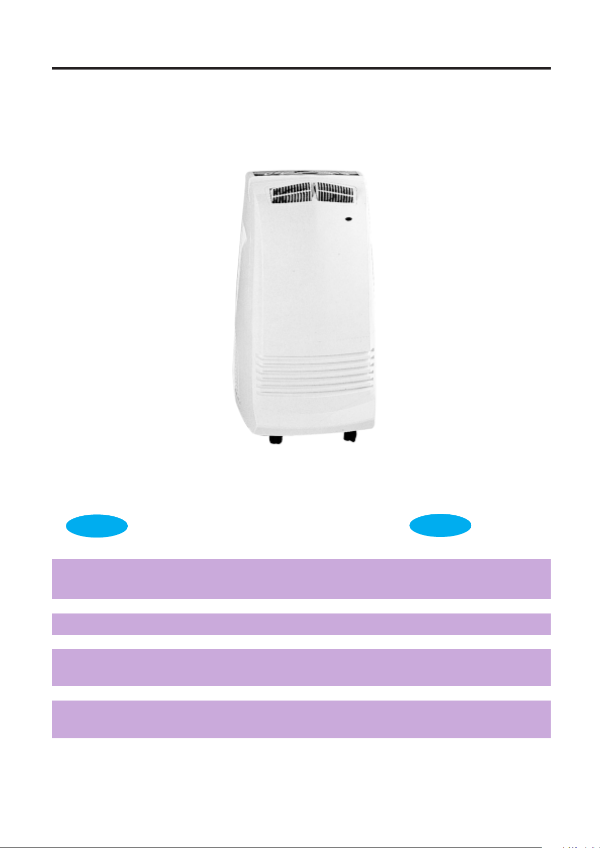
1. Mobile Air-conditioner (KY-20)
1.1 Summary
MODEL
NOTE
Mobile air-conditioner
-
3
-
Model
Function
Power source(PH-Hz-V)
Capacity
Power input
Current
Air volume
Dehumidifying capacity
C.O.P.
Upper fan speed
Power output
Fan capacitor
F
Upper fan type-pcs
Upper fan diameter length (mm-mm)
Evaporator
Rows-distance
Working area(m
2
)
Swing motor
Power-speed (W-r/min)
Control type
Fuse A
Working capacitor(
F)
Condenser
Rows-fin distance
Working area(m
2
)
Compressor
Model
Power
Protect device
Start method
Current
Working temp.
Compressor capacitor
Lower fan speed
Power output
Working capacitor
Lower fan type-pcs
Lower fan diameter-length (mm-mm)
Throttling method
Noise dB(A)
Net weight
Refrigerant
Refrigerant charge
Item
KY-20/(2001) KY-20/(2001)
Kcal/h
Btu/h
W
W
A
m
3
/h
m
3
/h
L/h
r/min
W
W
A
F
r/min
F
Width
Depth
Height
mm
mm
mm
Kg
Kg
Dimensions
1Ph 220~230V-50Hz
1720
6826
2000
3.5
290
340
2.63
1070/1010/940/900 (
30)
9
1.5
Centrifugal fan--1
146-160
Tin fin copper type
3-1.5
2.7
SM007U
4-4.1
Manual
0.01
Tin fin copper type
2-1.5
7.2
Sealed rotated type
625
P.C.S
3.1
Discharge temp.
115
1120 30
23
3
Centrifugal fan-1
196-82
Capillary
51.5
326
415
788
32
R22
Cooling
800
1.5
Controller 3.15 Transformer 1
2P14S225ANJ
MRA99025
30
0.55 0.51
Front side
Rear side
760
C-1R62H4J
MRA99094
20(
5%)
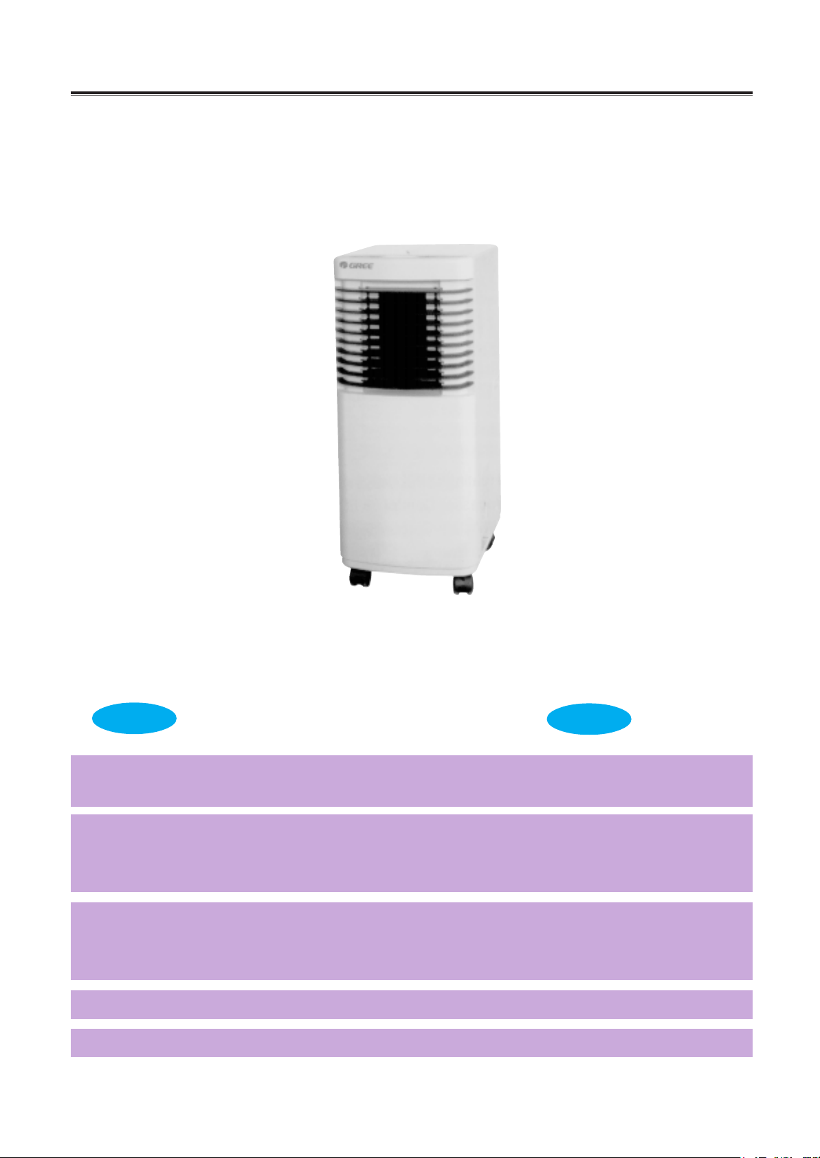
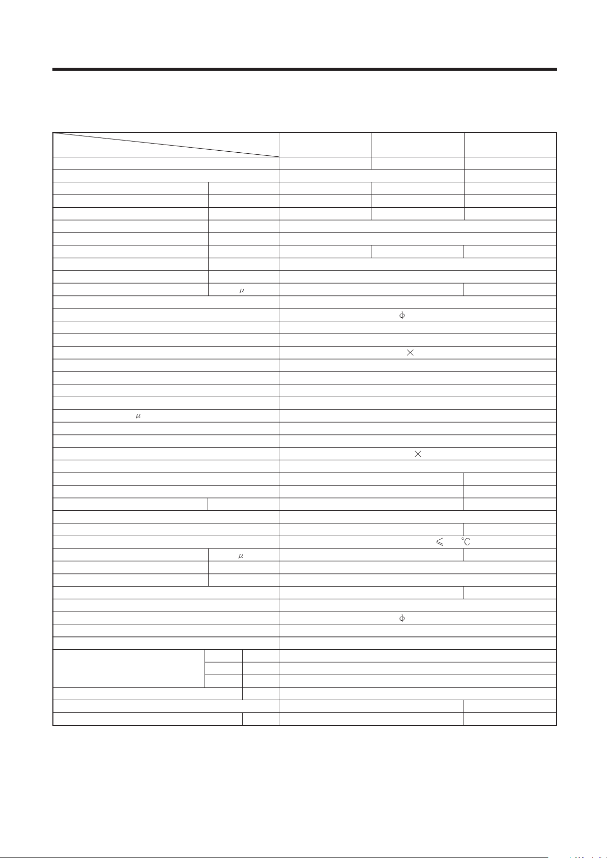
Table 1-1
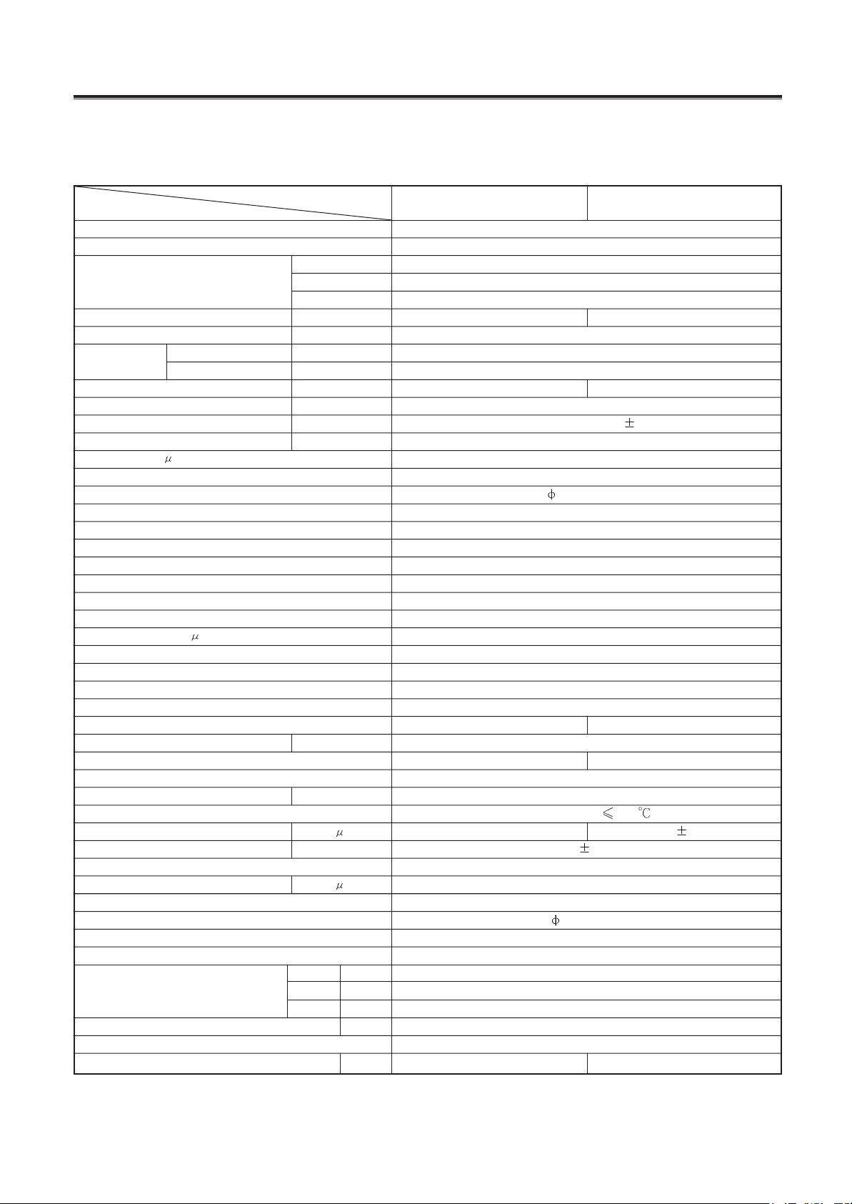
1.2 Technical specifications.
The technical data are subject to change without notice .Please refer to the nameplate of the unit.
1.3
Mobile air-conditioner
-
4
-
Model
Function
Power source(PH-Hz-V)
Capacity
Power input
Current
Air volume
Dehumidifying capacity
C.O.P.
Upper fan speed
Power output
Fan capacitor
F
Upper fan type-pcs
Upper fan diameter length (mm-mm)
Evaporator
Rows-distance
Working area(m
2
)
Swing motor
Power-speed (W-r/min)
Control type
Fuse A
Working capacitor(
F)
Condenser
Rows-fin distance
Working area(m
2
)
Compressor
Model
Power
Protect device
Start method
Current
Working temp.
Compressor capacitor
Lower fan speed
Power output
Working capacitor
Lower fan type-pcs
Lower fan diameter-length (mm-mm)
Throttling method
Noise dB(A)
Net weight
Refrigerant
Refrigerant charge
Item
KY-20N/(2001)
Kcal/h
Btu/h
W
W
A
m
3
/h
m
3
/h
L/h
r/min
W
W
A
F
r/min
F
Width
Depth
Height
mm
mm
mm
Kg
Kg
Dimensions
1Ph 220~230V-50Hz
1720
6826
2000
860
3.7
290
340
1.3
2.32
1070/1010/940/900 (
30)
9
1.5
Centrifugal fan--1
146-160
Tin fin copper type
3-1.5
2.7
SM007U
4-4.1
Manual
Controller3.15 Transformer 1
0.01
Tin fin copper type
2-1.5
7.2
Sealed rotated type
C-1RN57H5A
700W
MRA98730
P.C.S
3.1
Discharge temp.
115
15
1120
30
23
3
Centrifugal fan-1
196-82
Capillary
51.5
326
415
788
32
R407C
0.63
Cooling
Front side
Rear side
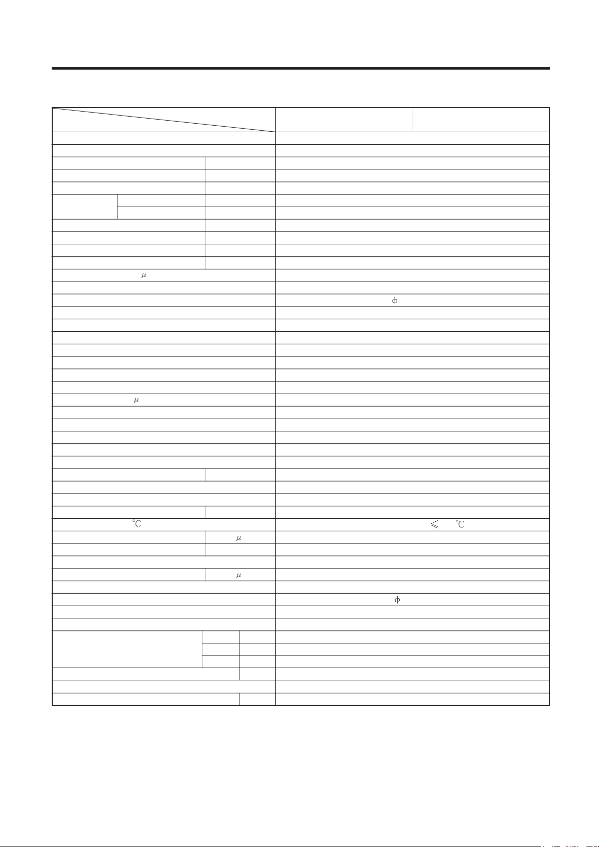
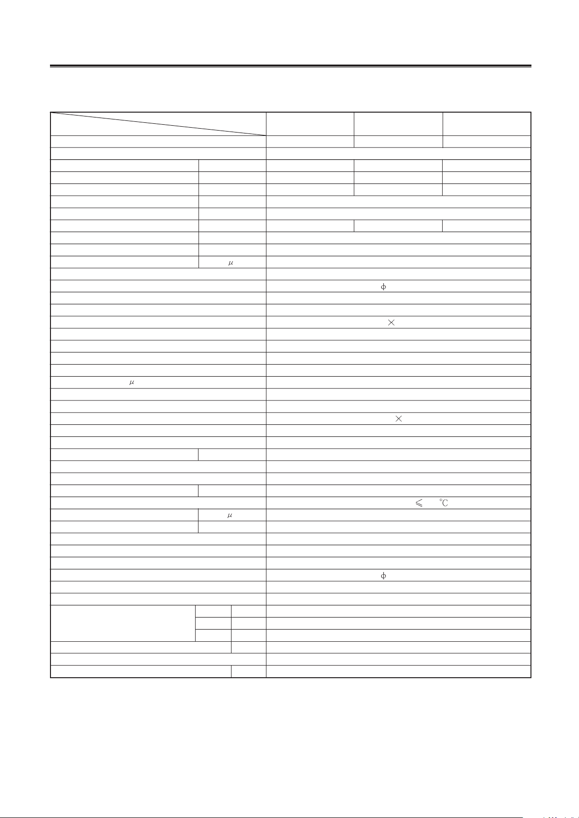
Table 1-2
The technical data are subject to change without notice .Please refer to the nameplate of the unit.
Mobile air-conditioner
-
5
-
Model
Function
Power source(PH-Hz-V)
Capacity
Power input
Current
Air volume
Dehumidifying capacity
C.O.P.
Upper fan speed
Power output
Fan capacitor
F
Upper fan type-pcs
Upper fan diameter length (mm-mm)
Evaporator
Rows-distance
Working area(m
2
)
Swing motor
Power-speed (W-r/min)
Control type
Fuse A
Working capacitor(
F)
Condenser
Rows-fin distance
Working area(m
2
)
Compressor
Model
Power
Protect device
Start method
Current
Working temp.
Compressor capacitor
Lower fan speed
Power output
Working capacitor
Lower fan type-pcs
Lower fan diameter-length (mm-mm)
Throttling method
Noise dB(A)
Net weight
Refrigerant
Refrigerant charge
Item
KY-20N/A
Kcal/h
Btu/h
W
W
A
m
3
/h
m
3
/h
L/h
r/min
W
W
A
F
r/min
F
Width
Depth
Height
mm
mm
mm
Kg
Kg
Dimensions
1Ph 220~230V-50Hz
1720
6826
2000
860
3.7
220
340
1.4
2.32
1180/1000
45
3
Centrifugal fan--1
146-160
Tin fin copper type
3-1.5
2.7
SM007U
4-4.1
Manual
Controller3.15 Transformer 1
0.01
Tin fin copper type
2-1.5
7.2
Sealed rotated type
NK134PAE
700
MRA12012-12026
PCS
3.3
Discharge temp.
115
25
1120
23
3
Centrifugal fan-1
196-82
Capillary
52.5
32.5
R407C
0.51
Cooling
Front side
Rear side
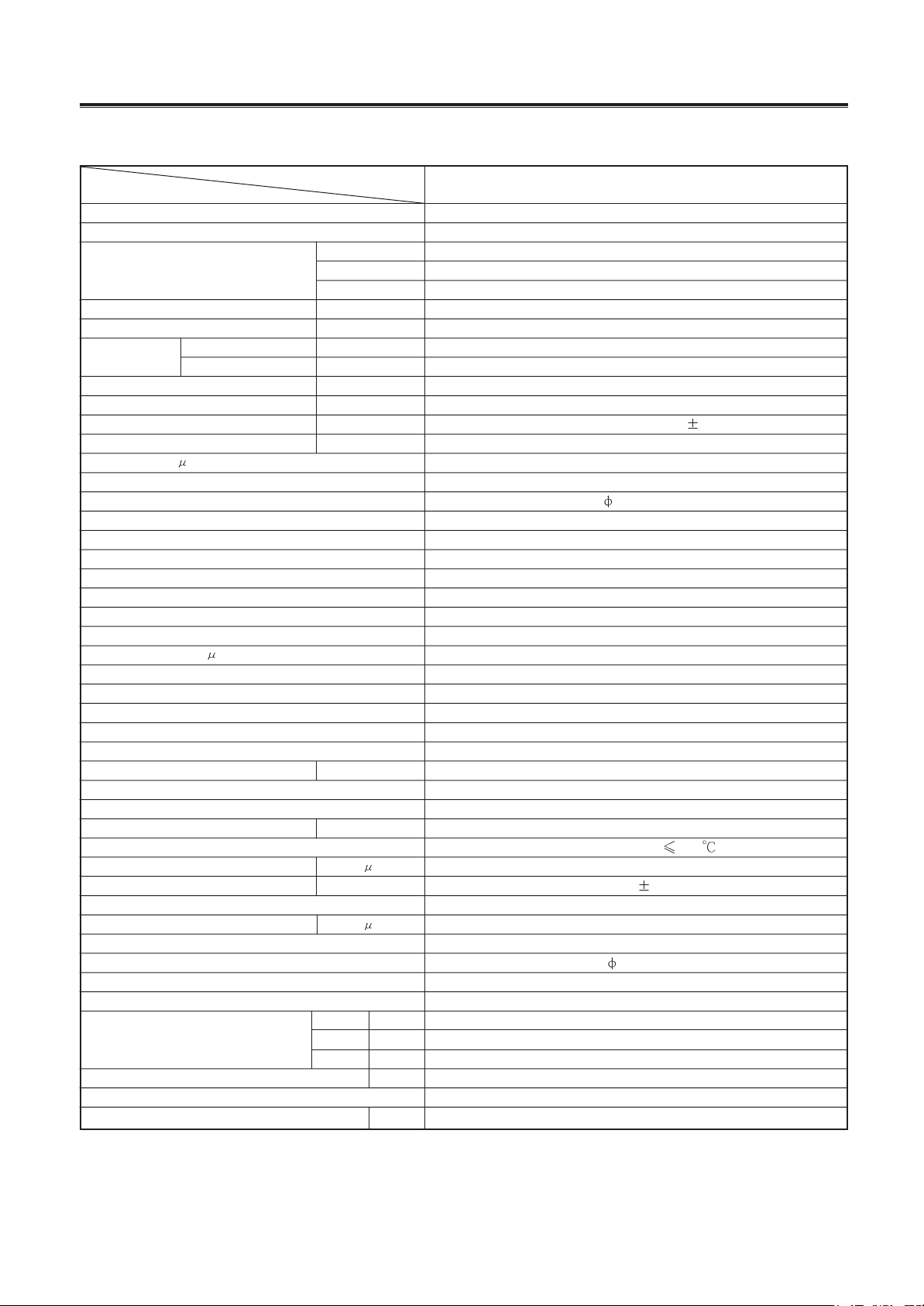
Table 1-3
The technical data are subject to change without notice .Please refer to the nameplate of the unit.
KY-20N/B
326
415
788
326
410
810
Mobile air-conditioner
-
6
-
Model
Function
Power source(PH-Hz-V)
Capacity
Power input
Current
Air volume
Dehumidifying capacity
C.O.P.
Fan speed
Power output
Upper fan capacitor(
F)
Upper fan type-pcs
Fan diameter length (mm-mm)
Evaporator
Rows-distance
Working area(m
2
)
Swing motor
Power-speed (W-r/min)
Control type
Fuse A
Working capacitor
F
Condenser
Rows-fin distance
Working area(m
2
)
Compressor
Model
Power
Protect method
Start method
Current
Working Capacitor
Compressor capacitor
Lower fan speed
Power output
Working capacitor
Lower fan type-pcs
Lower fan diameter-length (mm-mm)
Throttling method
Noise dB(A)
Net weight
Refrigerant
Refrigerant charge
Item
GP8-12L
W
W
A
m
3
/h
m
3
/h
L/h
r/min
W
W
A
F
r/min
F
Width
Depth
Height
mm
mm
mm
Kg
Kg
Dimensions
1Ph 115V-60Hz
2000
800
7.0A
290
340
1.3
2.5
1070/1010/940/900
9
3
Centrifugal fan--1
146-160
Tin fin copper type
3-1.5
2.7
SM007
4-4.1
Manual
Controller 3.15 Transformer 1
0.01
Tin fin copper type
2-1.5
7.2
Sealed rotated type
C-1R51H2E
650
MRA98637-9200
PCS
6.0
Discharge temp.
115
25
1200
23
11
Centrifugal fan-1
196-82
Capillary
51.5
326
415
788
32
R22
0.5
Cooling
Front side
Rear side
KY-20U/11156
Table 1-4
The technical data are subject to change without notice .Please refer to the nameplate of the unit.

Mobile air-conditioner
-
7
-
Model
Function
Power source(PH-Hz-V)
Capacity
Power input
Current
Air volume
Dehumidifying capacity
C.O.P.
Upper fan speed
Power output
Fan capacitor
F
Upper fan type-pcs
Upper fan diameter length (mm-mm)
Evaporator
Rows-distance
Working area(m
2
)
Swing motor
Power-speed (W-r/min)
Control type
Fuse A
Working capacitor(
F)
Condenser
Rows-fin distance
Working area(m
2
)
Compressor
Model
Power
Protect device
Start method
Current
Working temp.
Compressor capacitor
Lower fan speed
Power output
Working capacitor
Lower fan type-pcs
Lower fan diameter-length (mm-mm)
Throttling method
Noise dB(A)
Net weight
Refrigerant
Refrigerant charge
Item
KY-20U/A-11156
Kcal/h
Btu/h
W
W
A
m
3
/h
m
3
/h
L/h
r/min
W
W
A
F
r/min
F
Width
Depth
Height
mm
mm
mm
Kg
Kg
Dimensions
1Ph 115V-60Hz
1720
6826
2000
860
7.5
220
340
1.4
2.32
1180/1000
45
11
Centrifugal fan--1
146-160
Tin fin copper type
3-1.5
2.7
SM007
4-4.1
Manual
Controller3.15 Transformer 0.2
0.01
Tin fin copper type
2-1.5
7.2
Sealed rotated type
QA110CAD
770
MRA12105-12026
PCS
6.7
Discharge temp.
115
40
1200
23
11
Centrifugal fan-1
196-82
Capillary
52.5
32.5
R22
0.52
Cooling
Front side
Rear side
Table 1-5
The technical data are subject to change without notice .Please refer to the nameplate of the unit.
KY-20U/B-11156
326
415
788
326
410
810

Mobile air-conditioner
-
8
-
Model
Function
Power source(PH-Hz-V)
Capacity
Power input
Current
Air volume
Dehumidifying capacity
C.O.P.
Upper fan speed
Power output
Upper fan capacitor
F
Upper fan type-pcs
Fan diamete length (mm-mm)
Evaporator
Rows-distance
Working area(m
2
)
Swing motor
Power-speed (W-r/min)
Control type
Fuse A
Working capacitor
F
Condenser
Rows-fin distance
Working area(m
2
)
Compressor
Model
Power
Protect method
Start method
Current
Working capacitor
Compressor capacitor
Lower fan speed
Power output
Working capacitor
Lower fan type-pcs
Lower fan diameter-length (mm-mm)
Throttling method
Noise dB(A)
Net weight
Refrigerant
Refrigerant charge
Item
W
W
A
m
3
/h
m
3
/h
L/h
r/min
W
W
A
F
r/min
F
Width
Depth
Height
mm
mm
mm
Kg
Kg
Dimensions
1Ph 220~230V-50Hz
2000
760
3.5
290
340
1.3
2.63
1070/1010/940/900
9
2.5
Centrifugal fan--1
146-160
Tin fin copper type
3-1.5
2.7
SM007U
4-4.1
Manual
3.15/0.2
0.01
Tin fin copper type
2-1.5
7.2
Sealed rotated type
C-1R50H6K
625
MRA98635
PSC
3.3
Discharge temp.
115
17.5
1200
23
2.5
Centrifugal fan-1
196-82
Capillary
51.5
326
415
788
32
R22
0.53
Cooling
Front side
Rear side
GP8-22L
Table 1-6
The technical data are subject to change without notice .Please refer to the nameplate of the unit.
Mobile air-conditioner
-
9
-
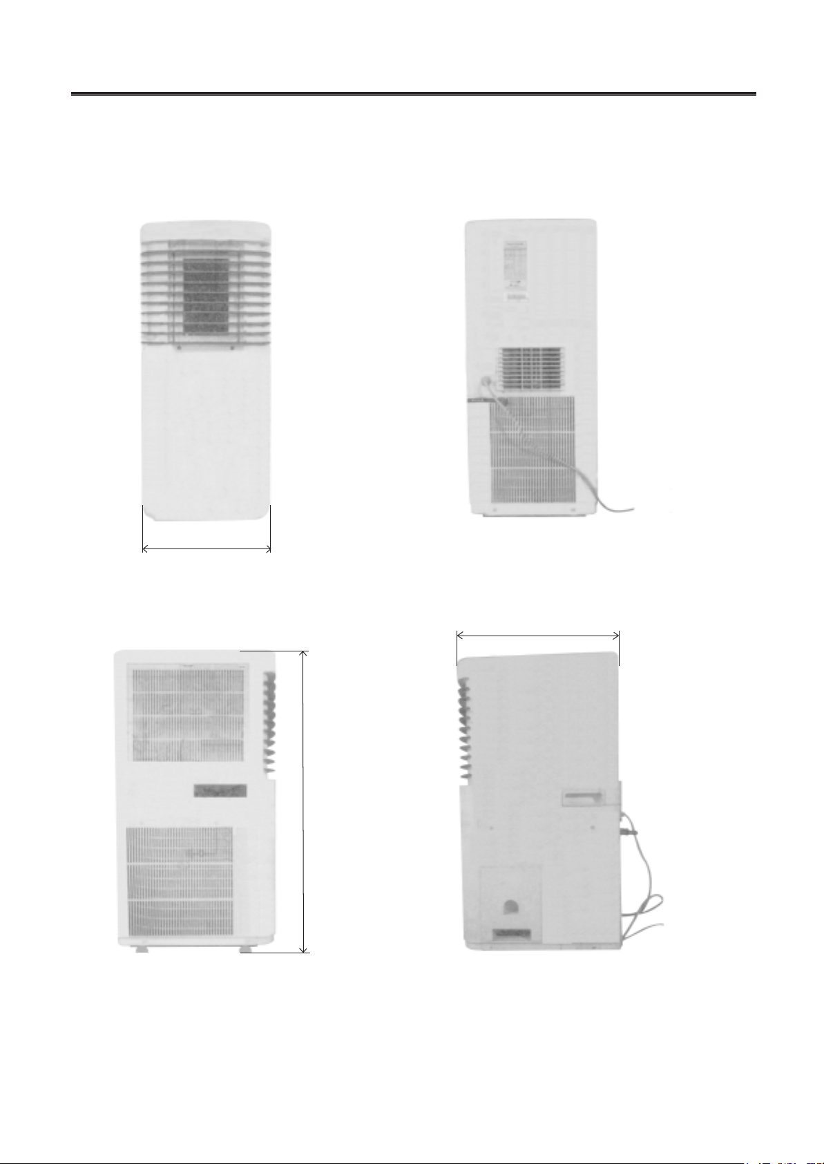
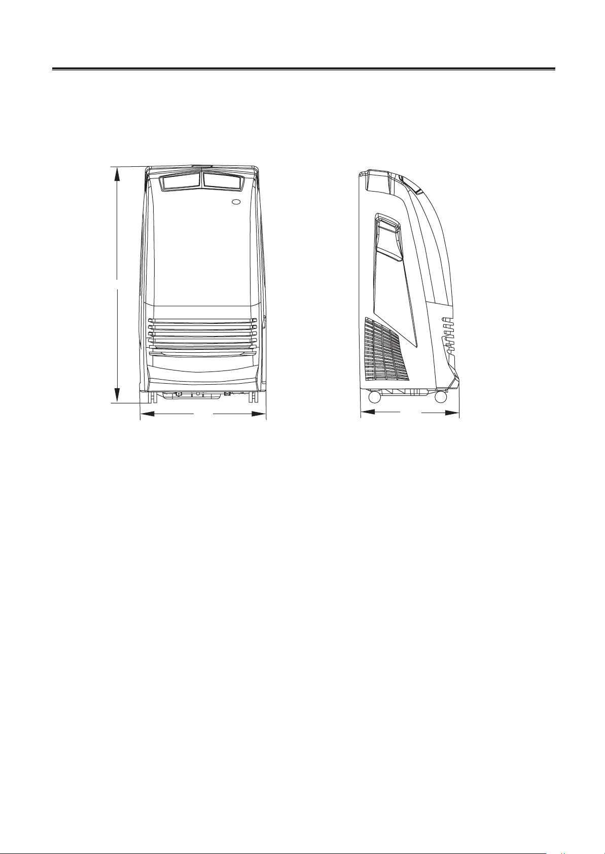
1.3 Outlines and dimensions
figure 1-2
326
Front
788
Left-side
Right-side
Rear
415
Mobile air-conditioner
-
10
-
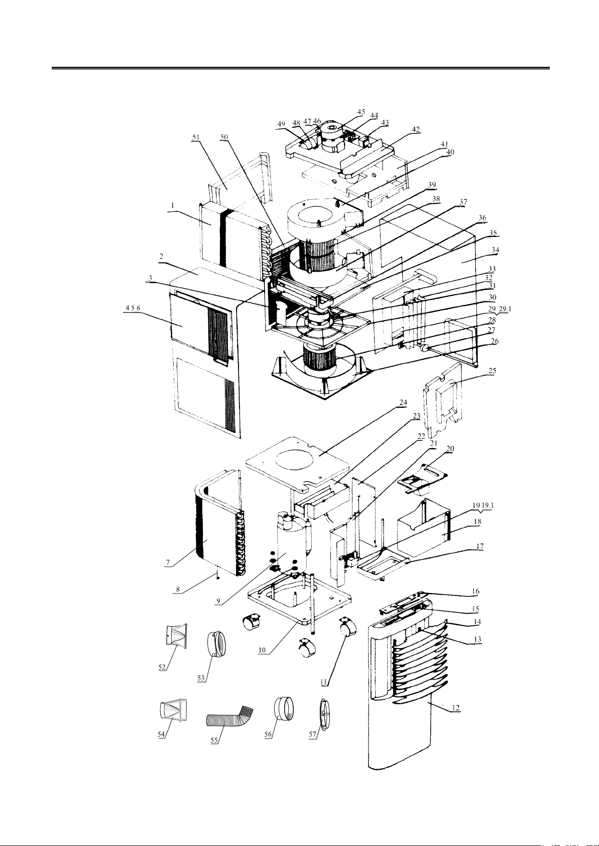
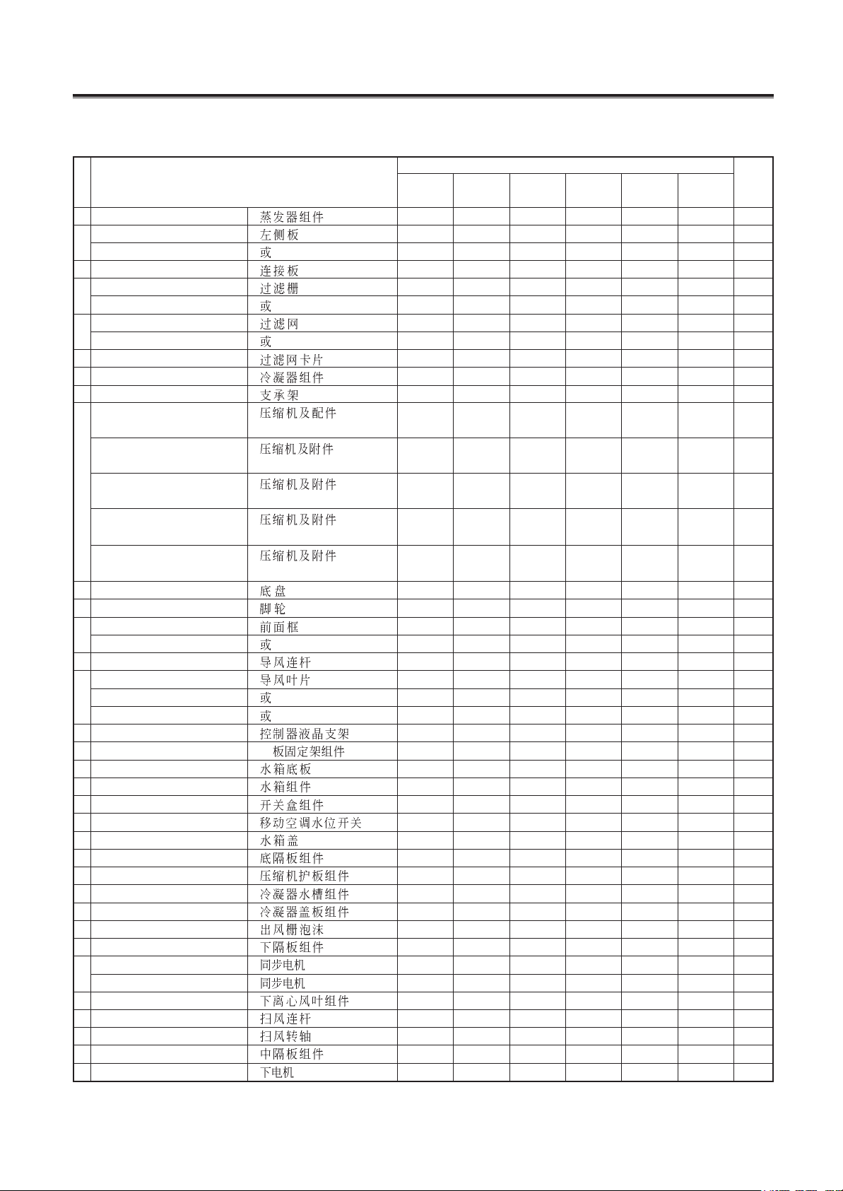
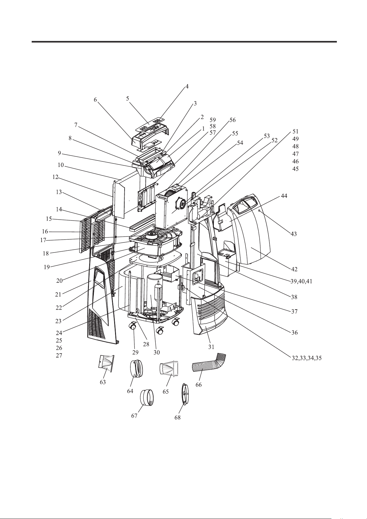
1.4 Explosive view
figure 1-3
Mobile air-conditioner
-
11
-
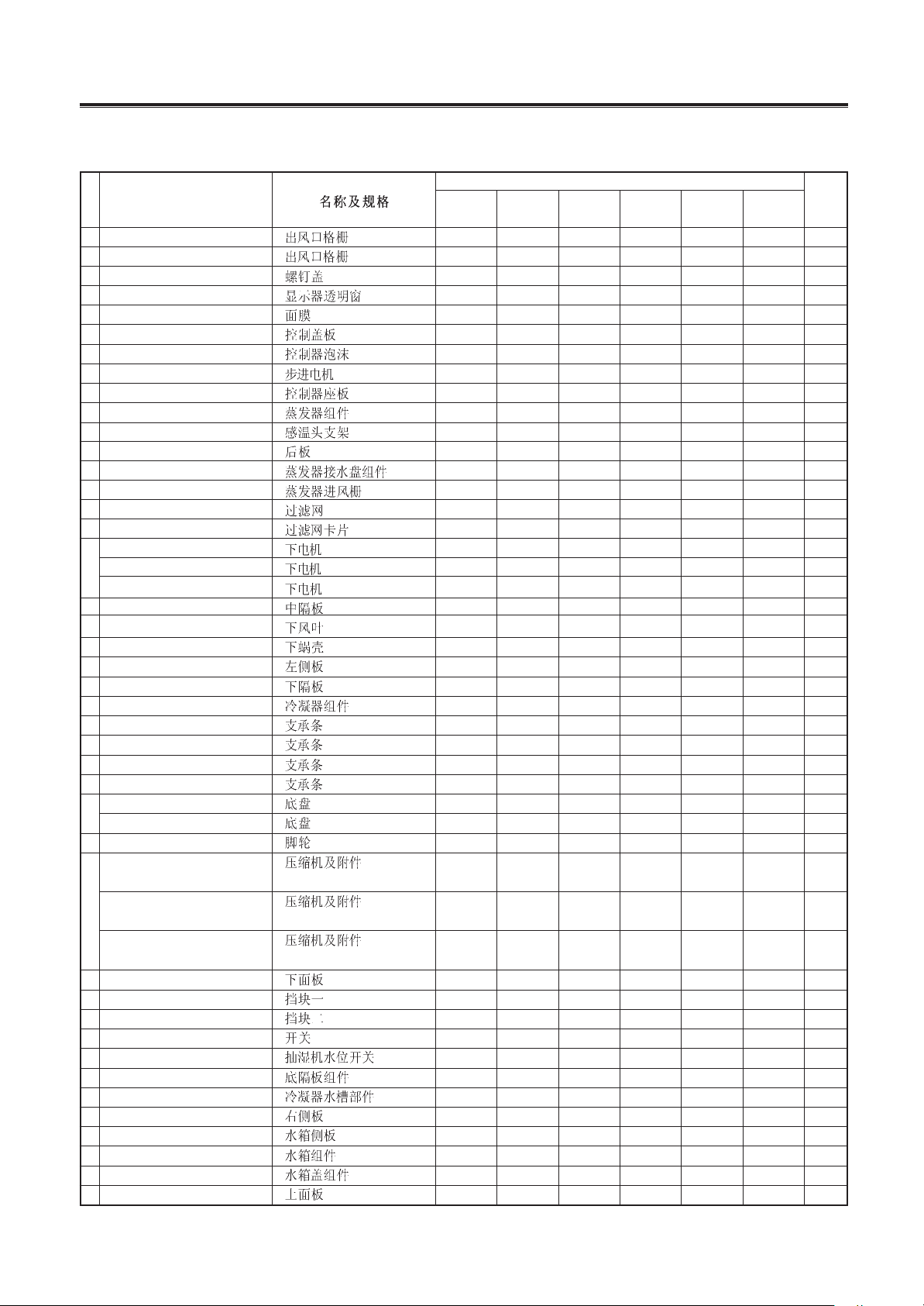
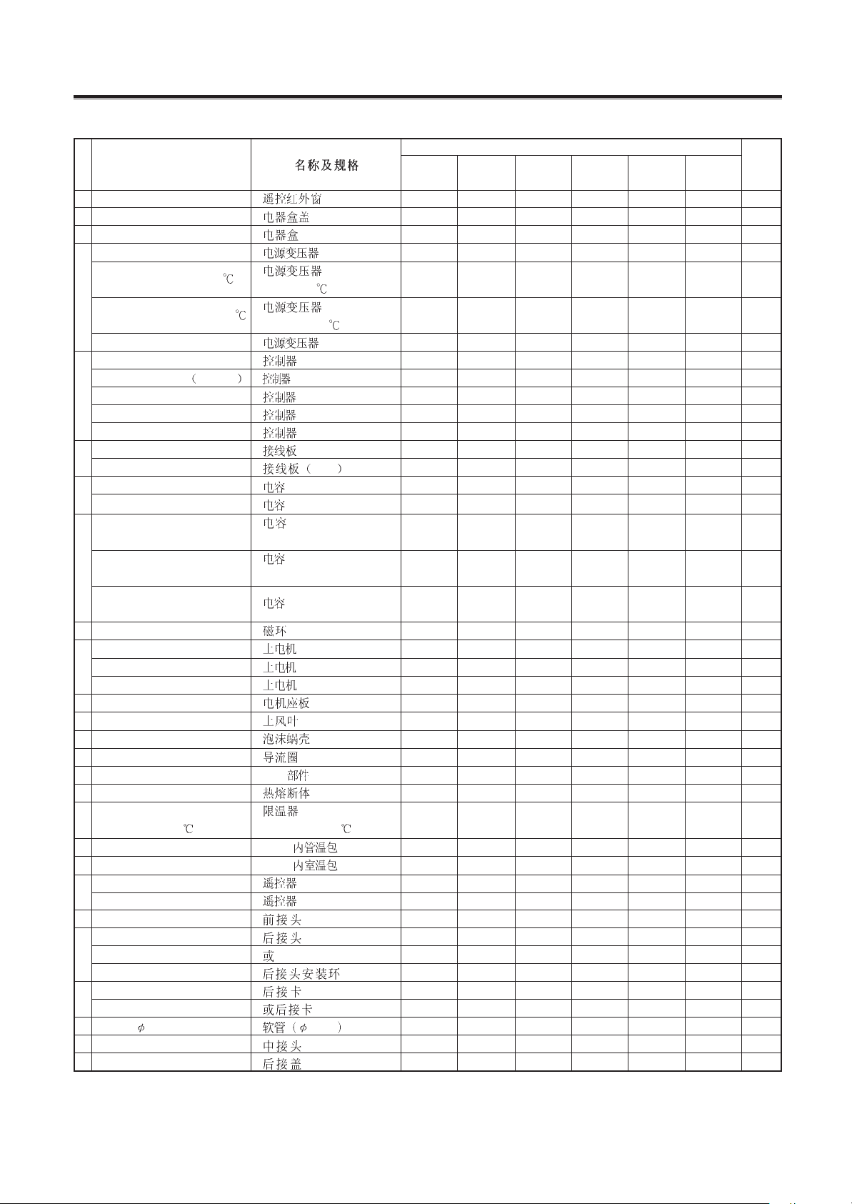
No.
Description
Part No.
Qty
1 evaporator 01036001 01036001 01036001 01036001 01036001 01036001 1
2
left case
20056022 20056022 20056022 20056020 20056022 20056022 1
or
20056023 20056023 20056023 \ 20056023 20056023 1
3 connection sheet
01386001 01386001 01386001 01386001 01386001 01386001 2
4
filter grill
22416002 22416002 22416002 22416002 22416002 22416002 1
or
22416003 22416003 22416003 22416003 22416003 22416003 1
5
filter
11126003 11126003 11126003 111260031 11126003 11126003 1
or
11126001 11126001 11126001 \ 11126001 11126001 1
6 filter fixer
26116012 26116012 26116012 26116012 26116012 26116012 6
7 condenser
01136011 01136011 01136011 01136011 01136011 01136011 1
8 supporting strip
01796002 01796002 01796002 01796002 01796002 01796002 4
compressor C-1R62H4J
00100312 \ \ \ \ \ 1
C-1R62H4J (VDE)
compressor 2P14S225ANJ
\ 00100005 \ \ \ \ 1
2P14S225ANJ
9 compressor C-1R50H6K
\ \ \ \ \ 00100307 1
C-1R50H6K
compressor C-1R51H2E
\ \ \ 00100308 00100308 \ 1
C-1R51H2E
compressor C-1RN57H5A
\ \ 00100337 \ \ \ 1
C-1RN57H5A
10 base assy
01216002 01216002 01216002 01216002 01216002 01216002 1
11 castor
24236051 24236051 24236051 24236051 24236051 24236051 4
12
front panel
26116005 26116005 26116005 26116004 26116005 26116005 1
or
26116006 26116006 26116006 \ 26116006 26116006 1
13 guide louver conjunction
10586002 10586002 10586002 10586001 10586002 10586002 2
air guide louver
10516003 10516003 10516003 10516002 10516003 10516003 10
14 or
10516004 10516004 10516004 \ 10516004 10516004 10
or
10516005 10516005 10516005 \ 10516005 10516005 10
15 LCD support
24216221 24216221 24216221 24216221 24216221 24216221 1
16 PCB support P
24226002 24226002 24226002 24226002 24226002 24226002 1
17 drain tank base
22226001 22226001 22226001 22226001 22226001 22226001 1
18 drain tank
20186005 20186005 20186005 20186005 20186005 20186005 1
19 switch assy
20106004 20106004 20106004 20106004 20106004 20106004 1
19.1
level switch 45026001 45026001 45026001 45026001 45026001 45026001 1
20 drain tank cover
22246002 22246002 22246002 22246002 22246002 22246002 1
21 back insulation plate
01236011 01236011 01236011 01236011 01236011 01236011 1
22 compressor protection plate
01496002 01496002 01496002 01496002 01496002 01496002 1
23 condenser tray
06126002 06126002 06126002 06126002 06126002 06126002 1
24 condenser cover
01176011 01176011 01176011 01176011 01176011 01176011 1
25 foam of outlet grill
52016104 52016104 52016104 52016104 52016104 52016104 1
26 lower insulation plate
20056031 20056031 20056031 20056031 20056031 20056031 1
27
swing motorSM007U
SM007U 15216001 15216001 15216001 \ \ 15216001 1
swing motor SM007
SM007 \ \ \ 15210207 15210207 \ 1
28 lower centrifugal fan
10316009 10316009 10316009 10316009 10316009 10316009 1
29 wing louver conjunction
10586008 10586008 10586008 10586007 10586008 10586008 1
29.1
axes 10566002 10566002 10566002 10566001 10566002 10566002 1
30 middle insulation plate
20056029 20056029 20056029 20056029 20056029 20056029 1
31 lower motor YD23D
YD23D 15016007 15016007 15016007 \ \ \ 1
KY-
20/(2001)
KY-
20/(2001)
KY-
20N/(2001)
KY-
20U/11156
GP8-12L GP8-22L
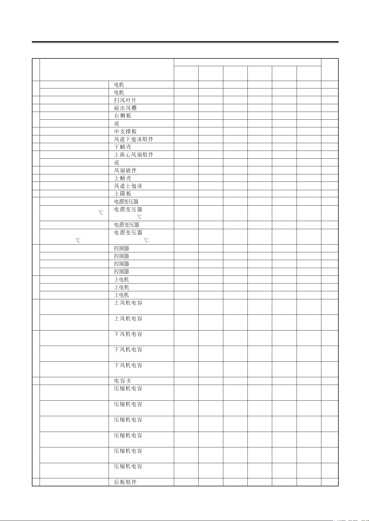
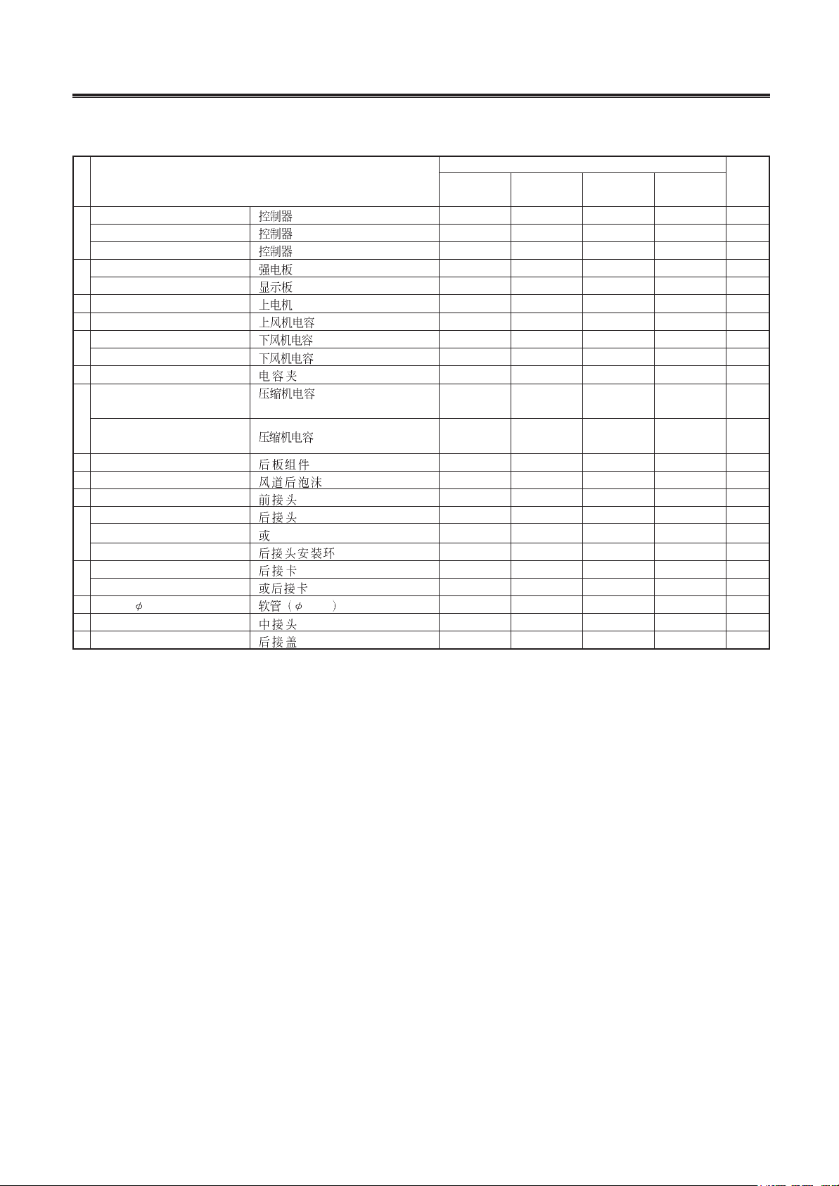
1.5 Spare parts list
Table 1-7
Mobile air-conditioner
-
12
-
31
lower motor YD23C
YD23C \ \ \ \ \ 15016005 1
lower motor YD23E
YD23E \ \ \ 15016008 15016008 \ 1
32 swing louver
10516029 10516029 10516029 10516028 10516029 10516029 5
33 air outlet grill
22416004 22416004 22416004 22416004 22416004 22416004 1
34
right case
20056015 20056015 20056015 20056013 20056015 20056015 1
or
20056016 20056016 20056016 \ 20056016 20056016 1
35 inside supporting plate
01796001 01796001 01796001 01796001 01796001 01796001 1
36 lower foam of duct
12316010 12316010 12316010 12316010 12316010 12316010 1
37 lower propeller house
22206002 22206002 22206002 22206002 22206002 22206002 1
38
upper centrifugal fan
10316008 10316008 10316008 10316008 10316008 10316008 1
or
10316005 10316005 10316005 10316005 10316005 10316005 1
39 fan nesting
10316002 10316002 10316002 10316002 10316002 10316002 1
40 upper propeller
22206001 22206001 22206001 22206001 22206001 22206001 1
41 upper foam of duct
12316201 12316201 12316201 12316201 12316201 12316201 1
42 upper insulation plate
20056025 20056025 20056025 20056024 20056025 20056025 1
transformer SC24V1
SC24V1 \ \ \ \ \ 43110166 1
transformer SC24(130
) 43110165 43110165 43110165 \ \ \ 1
SC24(115 )
43
transformer SC24B
SC24B \ \ \ \ 43110192 \ 1
transformer
\ \ \ 43110008 \ \ 1
SC24V3(130 ) SC24V3(130 )
PCB
6601A(M) 30026002 30026002 30026002 \ \ \ 1
44
PCB 6601D(M)
6601D(M) \ \ \ \ \ 30026005 1
PCB 6601C(M)
6601C(M) \ \ \ \ 30026003 \ 1
PCB 6601CF
6601CF \ \ \ 30026004 \ \ 1
upper motor YD9D
YD9D 15016003 15016003 15016003 \ \ \ 1
45 upper motor YD9C
YD9C \ \ \ \ \ 15016001 1
upper motor YD9E
YD9E \ \ \ 15016004 15016004 \ 1
upper motor capacitor
33010020 33010020 33010020 \ \ 33010020 1
46
1.5uF/450V(VDE)
upper motor capacitor
\ \ \ 33000010 33000010 \ 1
3uF/450VAC
lower motor capacitor
33010027 33010027 33010027 \ \ \ 1
3uF/450V(VDE)
47 lower motor capacitor
\ \ \ \ \ 33010019 1
2.5uF/450VAC
lower motor capacitor
\ \ \ 33000011 33000011 \ 1
11uF/300VAC
48 capacitor clamp
02146002 02146002 02146005 02146004 02146001 02146004 1
compressor capacitor
33010729 \ \ \ \ \ 1
20uF/450V(VDE) 20uF/450V(VDE)
compressor capacitor
\ 33000021 \ \ \ \ 1
20uF/450V(VDE) 30uF/450V
compressor capacitor
\ \ \ \ \ 33010731 1
49
17.5uF/400VAC 17.5uF/400VAC
compressor capacitor
\ \ \ \ 33000017 \ 1
25uF/450VAC 25uF/450VAC
compressor capacitor
\ \ 33010728 \ \ \ 1
15uF/450VAC 15uF/450VAC
compressor capacitor
\ \ \ 33000025 \ \ 1
25uF/330VAC 25uF/330VAC(UL)
50 rear case
20006006 20006006 20006006 20006006 20006006 20006006 1
No.
Description
Part No.
Qty
KY-
20/(2001)
KY-
20/(2001)
KY-
20N/(2001)
KY-
20U/11156
GP8-12L GP8-22L
Table 1-7 continue
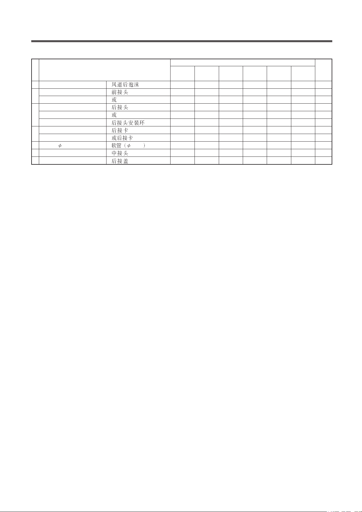
Mobile air-conditioner
-
13
-
51 rear foam of duct 12316202 12316202 12316202 12316202 12316202 12316202 1
52
front plastic pipe end
06646001 06646001 06646001 06646001 06646001 06646001 1
or
06646006 06646006 06646006 06646006 06646006 06646006 1
plastic pipe end
06646002 06646002 06646002 06646002 06646002 06646002 1
53 or
06646007 06646007 06646007 06646007 06646007 06646007 1
fixing ring
06646010 06646010 06646010 06646010 06646010 06646010 1
54
rear clip
26116010 26116010 26116010 26116010 26116010 26116010 1
or rear clip B
B 26116018 26116018 26116018 26116018 26116018 26116018 1
55 pipe (
131) 131 05236006 05236006 05236006 05236006 05236006 05236006 1
56 middle plastic pipe end
06646003 06646003 06646003 06646003 06646003 06646003 1
57 plastic cover
22246001 22246001 22246001 22246001 22246001 22246001 1
No.
Description
Part No.
Qty
KY-
20/(2001)
KY-
20/(2001)
KY-
20N/(2001)
KY-
20U/11156
GP8-12L GP8-22L
The data are subject to change without notice.
Table 1-7 continue
Mobile air-conditioner
-
14
-
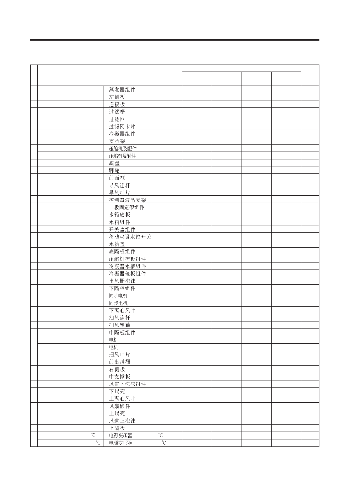
No.
Description
Part No.
Qty
1 evaporator 01036002 01036001 01036002 01036001 1
2 left case
20056022 20056061 20056020 20056061 1
3 connection sheet
01386001 01386001 01386001 01386001 2
4 filter grill
22416002 22416002 22416002 22416002 1
5 filter
11126003 11126003 111260031 111260031 1
6 filter fixer
26116012 26116012 26116012 26116012 6
7 condenser
01136012 01136011 01136012 01136011 1
8 supporting strip
01796002 01796002 01796002 01796002 4
9
compressor NK134PAE
NK134PAE 00100055 00100055 \ \ 1
compressor QA110CAD
QA110CAD \ \ 00120007 00120007 1
10 base assy
01216002 01216002 01216002 01216002 1
11 castor
24236051 24236051 24236051 24236051 4
12 front panel
26116005 26116025 26116004 26116025 1
13 guide louver conjunction
10586002 10586002 10586001 10586001 2
14 air guide louver
10516004 10516046 10516002 10516046 10
15 LCD support
\\\\\
16 PCB support P
\\\\\
17 drain tank base
22226001 22226001 22226001 22226001 1
18 drain tank
20186005 20186005 20186005 20186005 1
19 switch assy
20106004 20106004 20106004 20106004 1
19.1 level switch
45026001 45026001 45026001 45026001 1
20 drain tank cover
22246002 22246002 22246002 22246002 1
21 back insulation plate
01236011 01236011 01236011 01236011 1
22 compressor protection plate
01496002 01496002 01496002 01496002 1
23 condenser tray
06126002 06126002 06126002 06126002 1
24 condenser cover
01176011 01176011 01176011 01176011 1
25 foam of outlet grill
52016104 52016104 52016104 52016104 1
26 lower insulation plate
20056031 20056031 20056031 20056031 1
27
swing motorSM007U
SM007U 15216001 15216001 \ \ 1
swing motor SM007
SM007 \ \ 15210207 15210207 1
28 lower centrifugal fan
10316006 10316006 10316006 10316006 1
29 wing louver conjunction
10586008 10586008 10586007 10586007 1
29.1
axes 10566002 10566002 10566001 10566001 1
30 middle insulation plate
20056029 20056029 20056029 20056029 1
31
lower motor YD45U
YD45U \ \ 15016012 15016012 1
lower motor YD45A
YD45A 15016011 15016011 \ \ 1
32 swing louver
10516029 10516029 10516028 10516028 5
33 air outlet grill
22416004 22416004 22416004 22416007 1
34 right case
20056015 20056060 20056013 20056060 1
35 inside supporting plate
01796001 01796001 01796001 01796001 1
36 lower foam of duct
12316010 12316010 12316010 12316010 1
37 lower propeller house
22206004 22206004 22206004 22206004 1
38 upper centrifugal fan
10316004 10316004 10316004 10316004 1
39 fan nesting
10316002 10316002 10316002 10316002 1
40 upper propeller
22206003 22206003 22206003 22206003 1
41 upper foam of duct
12316201 12316201 12316201 12316201 1
42 upper insulation plate
20056043 20056062 200560431 20056062 1
43
transformer SC24(130
) SC24(130 ) 43110165 43110165 \ \ 1
transformer SC24V3(115
) SC24V3(115 ) \ \ 43110008 43110008 1
KY-
20N/A
KY-
20N/B
KY-
20U/A-11156
KY-
20U/B-11156
Table 1-8
Mobile air-conditioner
-
15
-
No.
Description
Part No.
Qty
PCB 7901
7901 30027044 30027044 \ \ 1
44 PCB 7901C
7901C \ \ 30027045 \ 1
PCB 6701C
6701C \ \ \ 30026746 1
44
Hi-Volt PCB 7901
7901 \ 30000721 \ \ 1
LED Board 6701
6701 \ 30546701 \ \ 1
45 upper motor YD9C
YD9C \ \ \ \ \
46 upper motor capacitor
3uF/450VAC \ \ \ \ \
47
lower motor capacitor
3uF/450V(VDE) 33010027 33010027 \ \ 1
lower motor capacitor
11uF/300V(UL) \ \ 33000011 33000011 1
48 capacitor clamp
02146004 02146004 02146001 02146001 1
compressor capacitor
25uF/450V
33000020 33000020 \ \ 1
49
25uF/450V(VDE)(TUV) (VDE)(TUV)
compressor capacitor
40uF/300V(UL) \ \ 33010724 33010724 1
40uF/300V(UL)
50 rear case
20006006 20006006 20006006 20006006 1
51 rear foam of duct
12316202 12316202 12316202 12316202 1
52 front plastic pipe end
06646001 06646001 06646001 06646001 1
plastic pipe end
06646002 06646002 06646002 06646002 1
53 or
06646007 06646007 06646007 06646007 1
fixing ring
06646010 06646010 06646010 06646010 1
54
rear clip
26116010 26116010 26116010 26116010 1
or rear clip B
B 26116018 26116018 26116018 26116018 1
55 pipe (
131) 131 05236006 05236006 05236006 05236006 1
56 middle plastic pipe end
06646003 06646003 06646003 06646003 1
57 plastic cover
22246001 22246001 22246001 22246001 1
KY-
20N/A
KY-
20N/B
KY-
20U/A-11156
KY-
20U/B-11156
Table 1-8 continue
The data are subject to change without notice.
Mobile air-conditioner
-
16
-
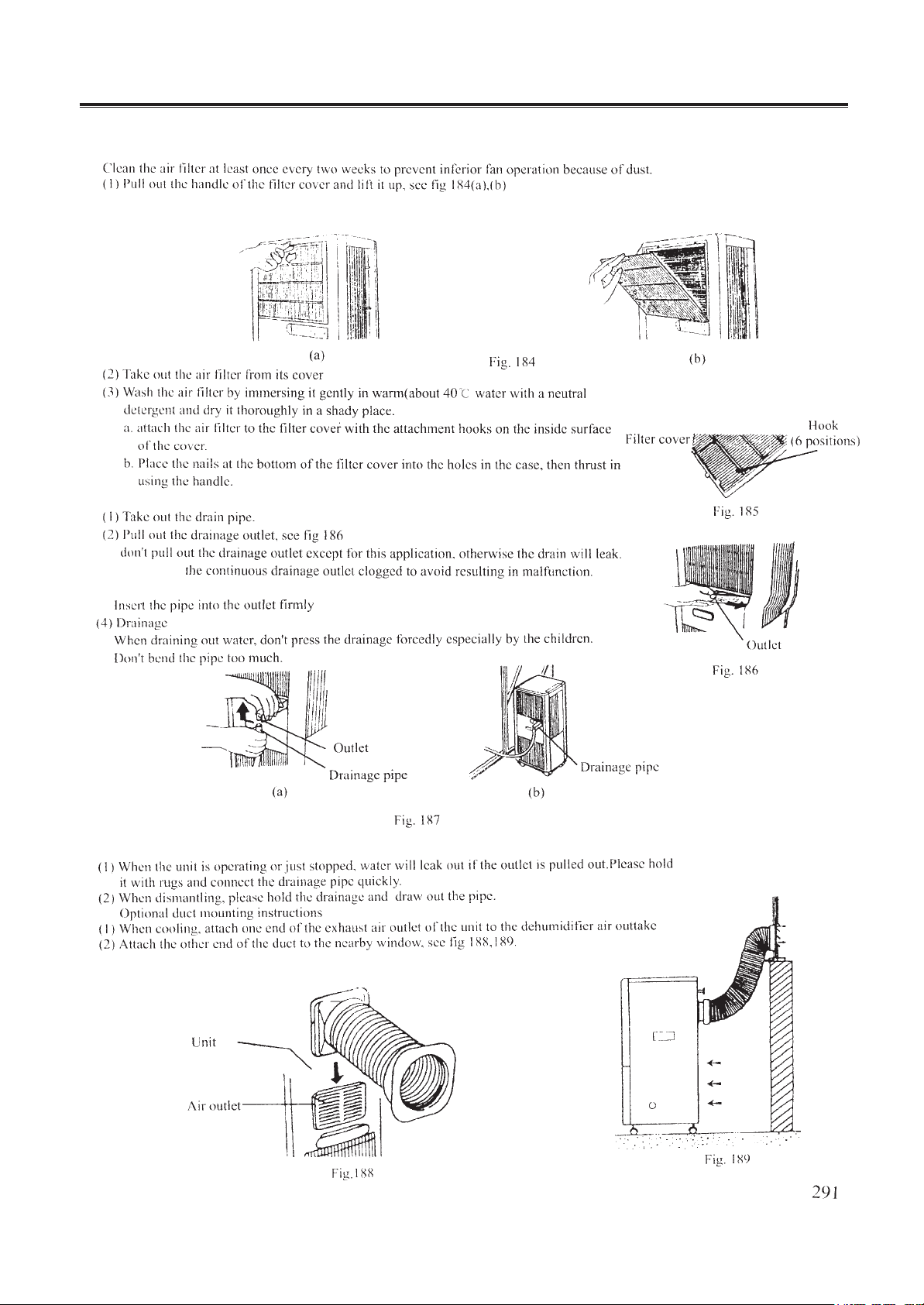
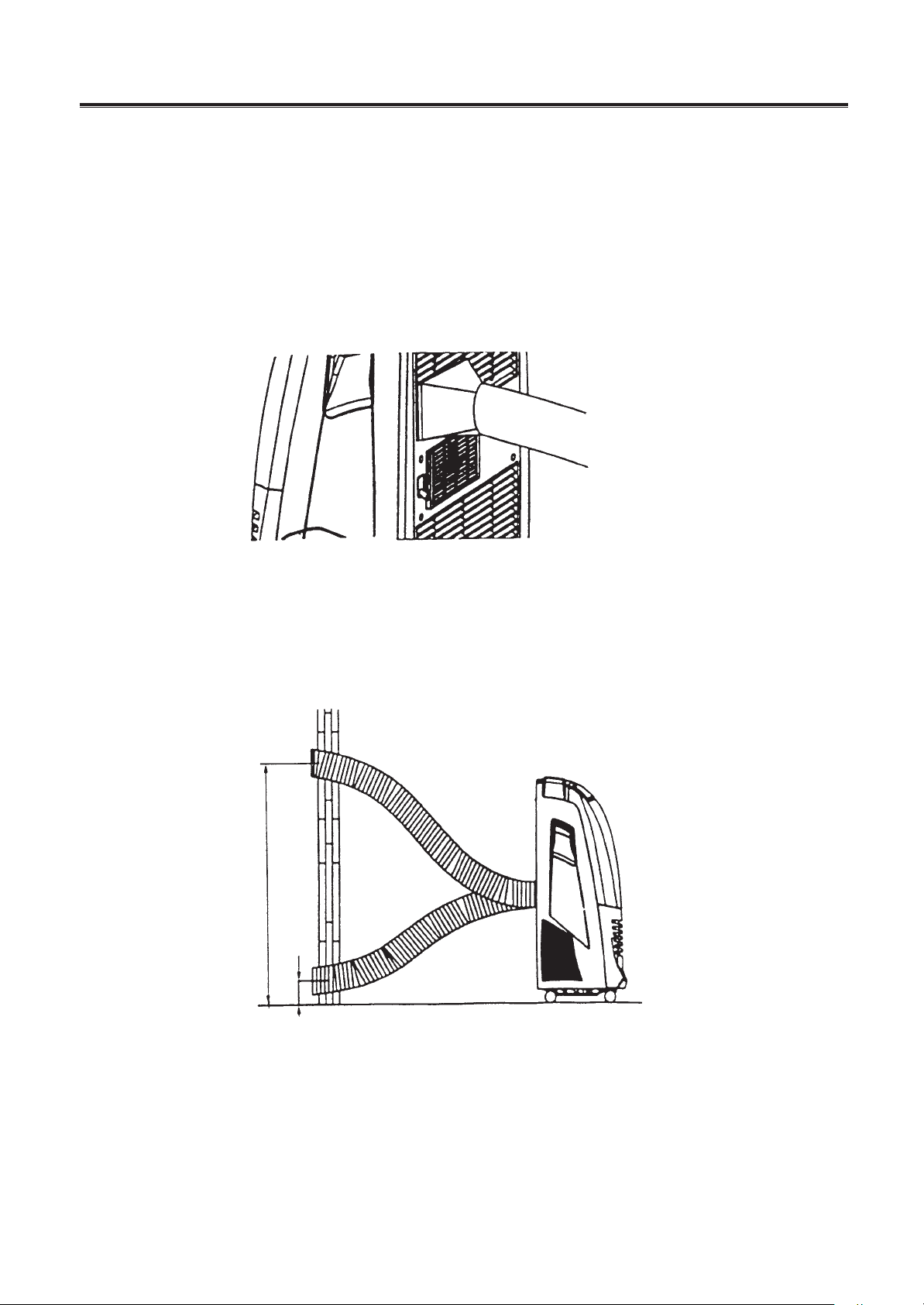
1.6 Installation guide
1.Installation of the air filter
2. Method of continous drainage
3. Caution
(3) Hold the continuous drainage outlet and insert the pipe see fig 187(a),(b)
don’t make
Mobile air-conditioner
-
17
-
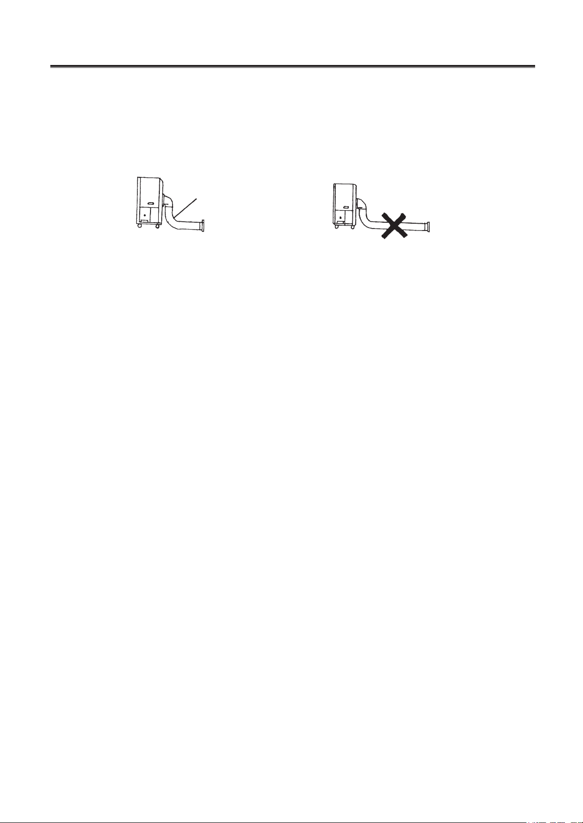
4. Note
try not to connect the exhaust pipe to the unit in dehumidifying operatton
don’t put heavy objects or step on the exhaust pipe. or it will be deformed and reduce cooling capacity.
don’t bend the pipe more than 2 circles, see fig190
don’t connect other pipes to the exhaust pipe, see fig191
don’t use the unit in heavy raining and windy days, or the water may be flow inside to cause malfunction.
Only one bend
Fig. 190
Fig. 191
Mobile air-conditioner
-
18
-
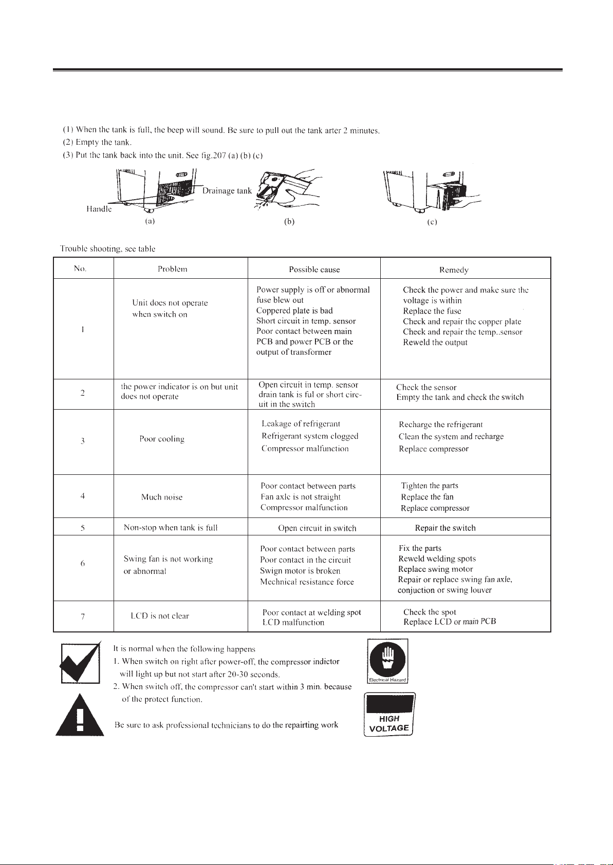
5. Drainage
6. Trouble-shooting
Cut off the power befor repairing
or it will be dangerous.
Be cautious of high voltage on
terminal board, upper fan motor
lower fan motor and compressor.
Mobile air-conditioner
-
19
-
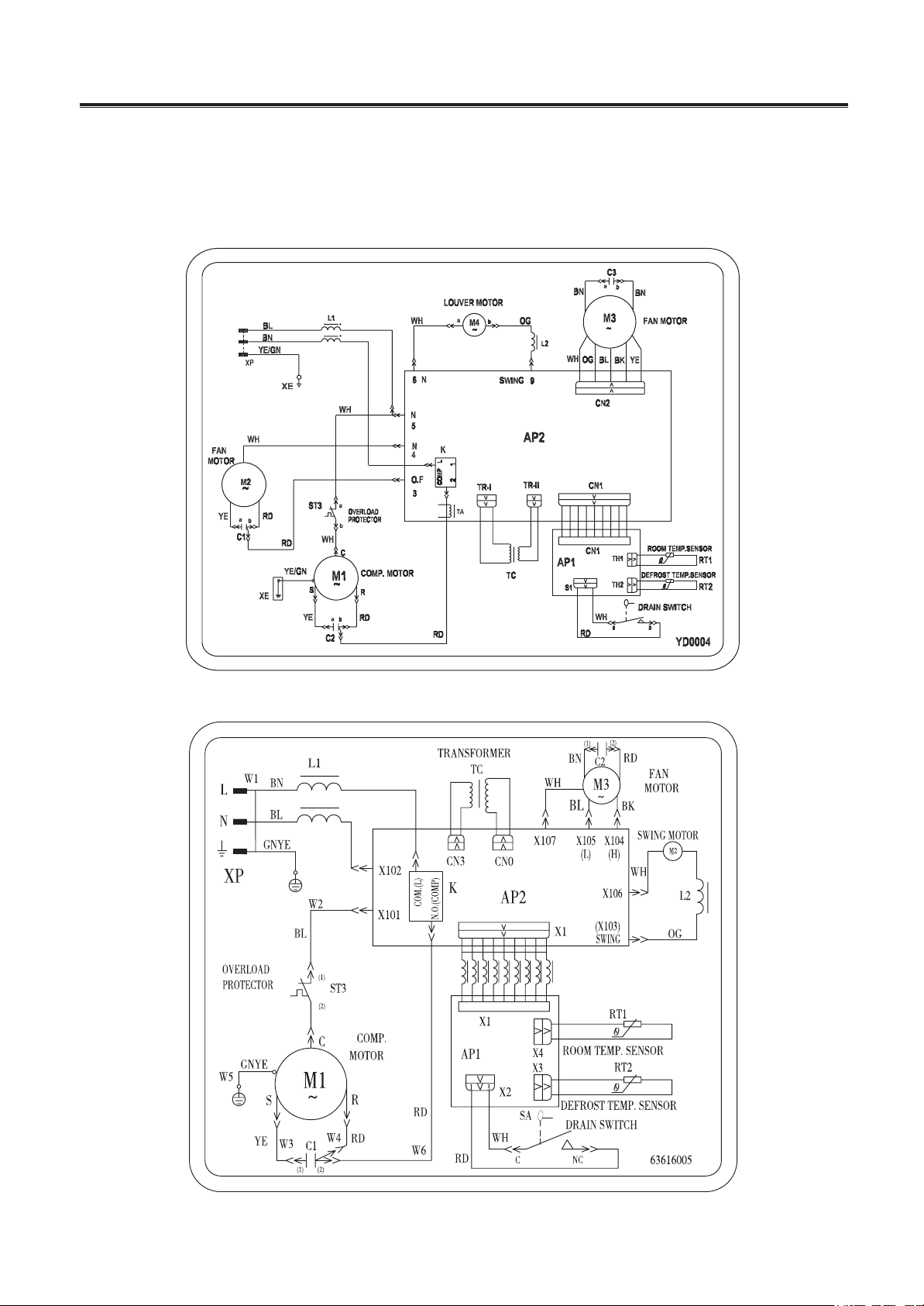
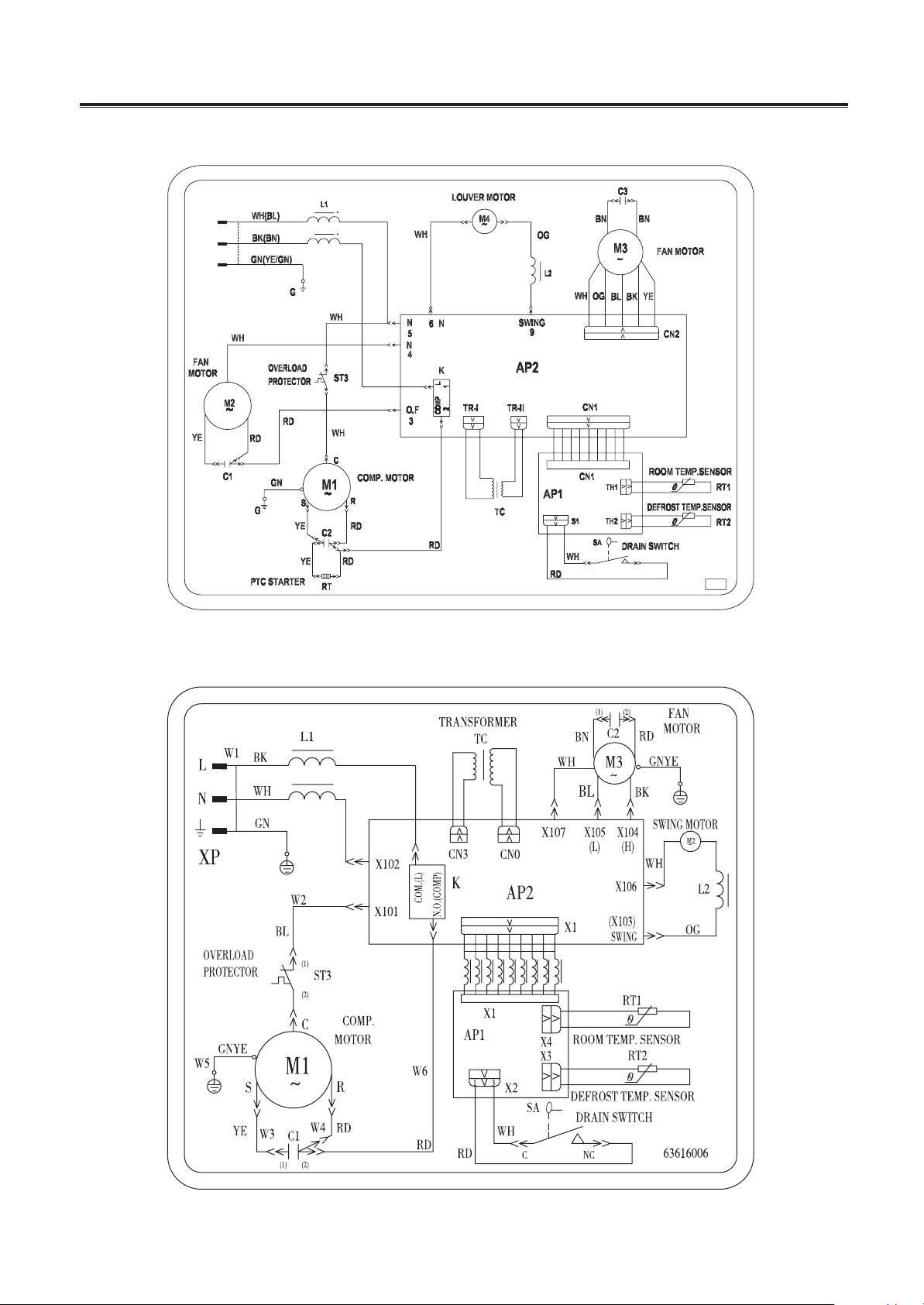
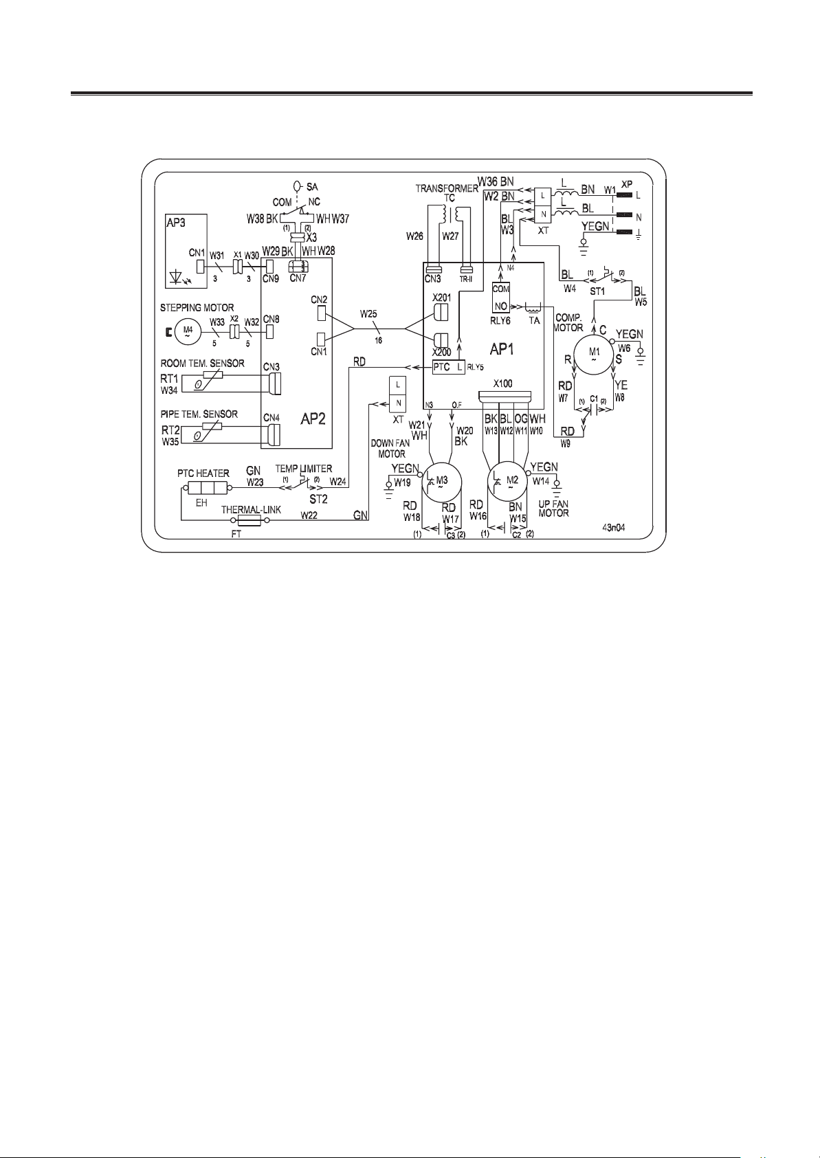
KY-20/(2001) KY-20N/(2001)
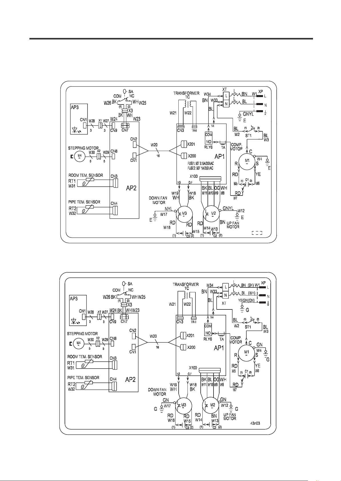
1.7 Circuit diagram
These circuit diagrams are subject to change without notice.
Please refer to the ones stuck on the machines.
figure 1-4
KY-20N/A KY-20N/B
Mobile air-conditioner
-
20
-
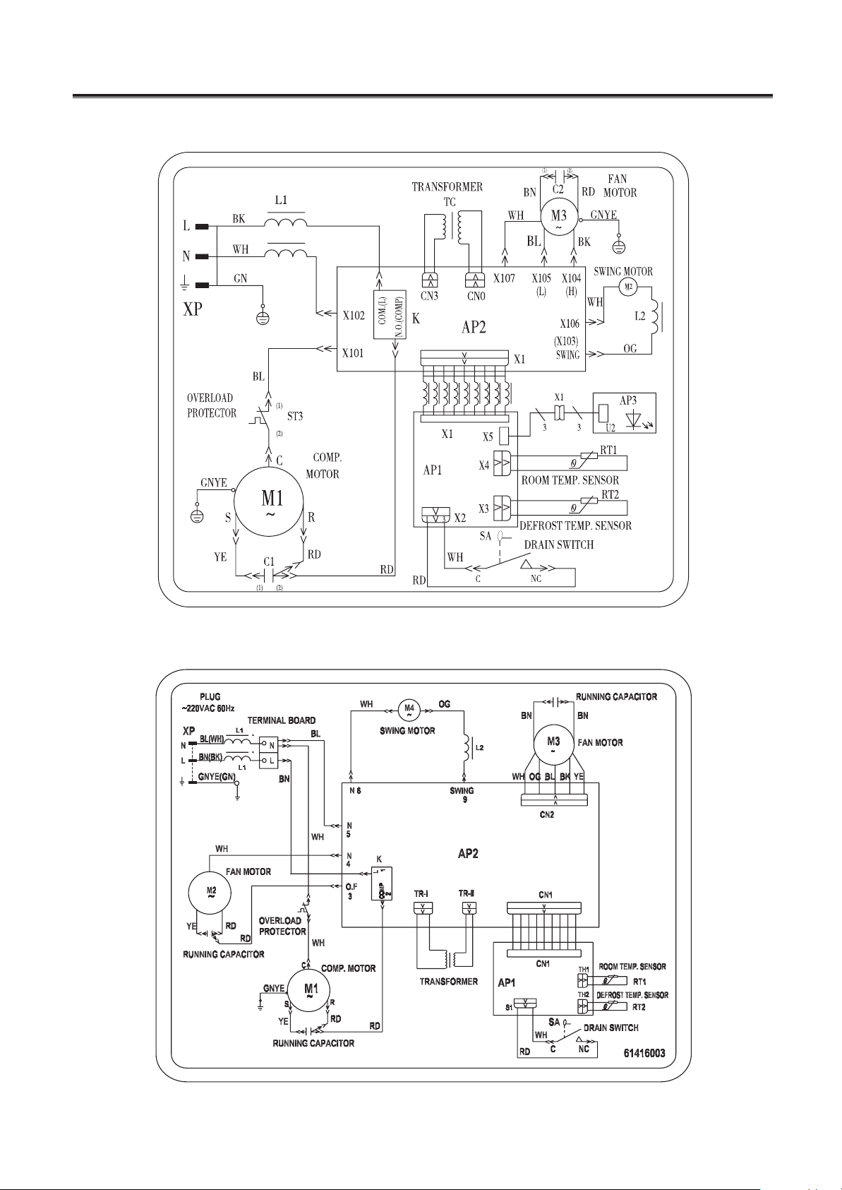
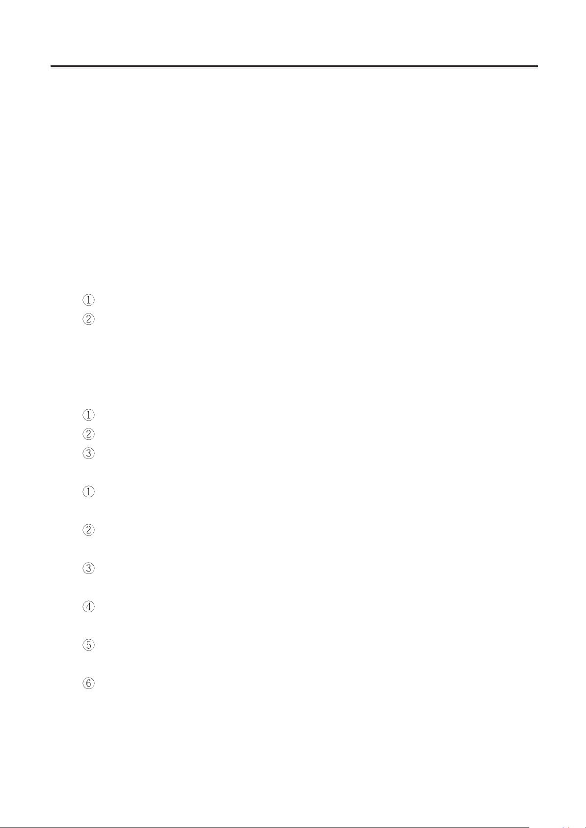
XP
GP8-12L KY-20U/11156
KY-20U/A-11156
figure 1-5
Mobile air-conditioner
-
21
-
KY-20U/B-11156
figure 1-6
GP8-22L
Mobile air-conditioner
-
22
-
The PCB function manual
of the Mobile Air-conditioner
1. Running mode:
1) FAN; 2) COOL; 3) DRY
2. Controlling modes:
1) Control panel
3. The parameter to be input:
1) Analog quantity
the ambient temperature of the indoor unit(shorten form is TIN)
the evaporator of the indoor unit (shorten form is Teva)
2) Switch quantity: the switch of the higher water level
3) Controlled input: by the controlling panel
4. The parameter to be output(controlled parameter)
1) Output of the relay
Indoor fan motor(2-speed)
Sweep fan motor
Compressor
2) Output quantity of LED:
the light displaying COOL mode(LED1 green)
it is light at the COOL mode, or else goes out
the light displaying DRY mode(LED2 green)
it is light at the DRY mode, or else goes out
the light displaying FAN mode(LED3 green)
it is light at the FAN mode, or else goes out
the light displaying indoor fan motor at high speed(LED4 yellow)
it is light when the indoor fan motor is at the high speed , or else goes out
the light displaying indoor fan motor at low speed(LED5 yellow)
it is light when the indoor fan motor is at the low speed , or else goes out
the light displaying SWING mode(LED6 green)
it is light when the swing fan motor is running , or else goes out
Flash:
a. Once go into Avoiding freezing mode, the relative LED flashes.
b. When water tank is full, the relative fan speed LED and mode LED flashes.
1.8 PCB function manual
Mobile air-conditioner
-
23
-
3) Others
Beeper whistles when turn on unit or press key validly, continuously whistles 8 times when
detecting water full.
5. The basal control modes:
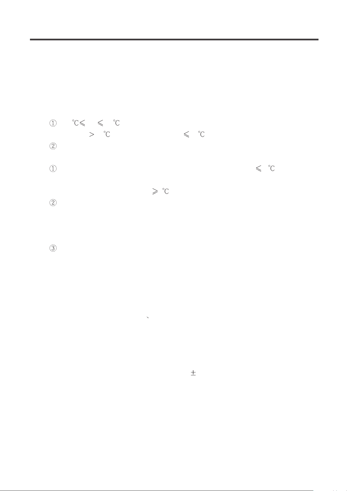
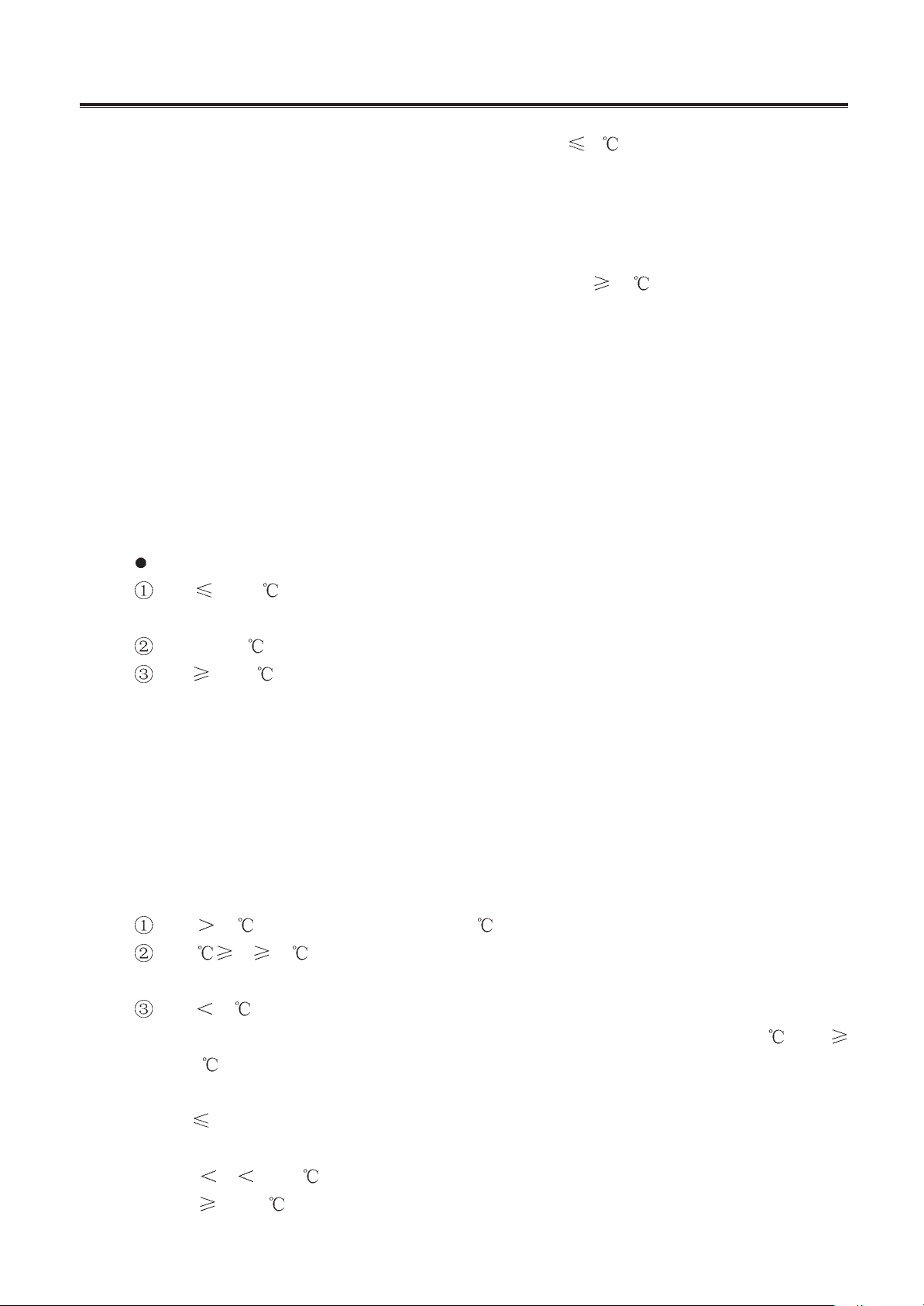
A. cooling mode:
1) The cooling conditions and process:
if 16 T
IN
45 , cooling mode act, compressor and fan motor run, relating LED
light, if T
IN
45 , compressor stop, if T
IN
16 , compressor and fan motor stop.
System starts to work, run in this mode, the initial fan speed is high.
2) The protecting functions:
Avoiding freezing: once the compressor work for 15min,when T
eva
-2 for over 2min,
compressor stop, the relative mode LED (about cooling or drying) flashes, After the com-
pressor stops for 4min and T
eva
8 , unit comes back to run.
The protection for the full water:
If the water tank is full, the higher water switch is close, the beeper will alarm “click, click”
8 times, the relative mode LCD (about cooling or drying) and fan speed LCD (about high
speed or low speed) flash, after 5sec, compressor stop
Delay protection for the compressor:
The distance between 2 times running won’t less than 3min, once the compress work and
it will not stop by the changing of the temperature in the next 6min.
B. Drying mode: The indoor fan motor runs in the low speed, compressor and outdoor unit
fan motor run continually, the protection functions are same as the cooling mode.
C. Fanning mode: Compressor stop, fan motor run in high or low speed. There is not the
protecting for avoiding freezing
for the full water and for the compressor in this mode.
6. Other control
1) Testing functions:
Turn on the unit when the FAST is short circuit, there is no delay protection for compressor
and others functions are all same as the normal state.
2) Unit can work normally in the range of AC 215
45V.
There is a short circuit protecting in the circuit.
7. Buttons on the control panel:
If press the button validly, the beeper whistles one times, LCD indicates the relative conditions,
system does after 2 seconds.
1) ON/OFF button:
Use it to control the unit on or off, After turn off the unit, only can use the ON/OFF button.
2) MODE button:

Mobile air-conditioner
-
24
-
Turn on the unit, press this button, unit circularly come into COOL DRY FAN mode, the
relative mode LCD lights.
3) Fan speed button:
Turn on the unit, in COOL and FAN mode, press this button, switch the high/low speed; in
DRY mode, run in low speed, this button is not usable. The relative LCD lights
4) Sweeping button
Turn on the unit, when indoor fan motor is in ON state, press this button to control the sweep
fan motor on or off; when indoor fan motor is in OFF state, the same to the sweep fan motor.
The relative LCD indicates the SWEEP mode.
Mobile Air-conditioner
-
25
-
MODEL
KY-32/K101
KYD-32/K101
GP12-22L
GP12-12L
GP12-12R
KY-32U/11156
NOTE
CE STANDARD
1Ph 220-230V 50Hz R407C
1Ph-220V 60Hz R22
1Ph-115V 60Hz R22
UL STANDARD
1Ph-115V 60Hz R22
2. Mobile Air-conditioner (KY-32)
2.1 Summary
figure 2-1
Mobile Air-conditioner
-
27
-
Model
Function
Power source(PH-Hz-V)
Capacity
Power input
Current
Air volume
Dehumidifying capacity
C.O.P.
Upper fan speed
Power output
Fan capacitor
Upper fan type-pcs
Upper fan diameter length (mm-mm)
Evaporator
Rows-distance
Working area
Swing motor
Power-speed (W-r/min)
Control type
Fuse A
Working capacitor
F
Condenser
Rows-fin distance
Working area
Compressor
Model
Power
Protect device
Start method
Current
Working temp.
Compressor capacitor
Lower fan speed
Power output
Working capacitor
Lower fan type-pcs
Lower fan diameter-length (mm-mm)
Throttling method
Noise dB(A)
Net weight
Refrigerant
Refrigerant charge
Item
KYD-32/K101
W
W
A
m
3
/h
L/h
r/min
W
F
A
F
r/min
W
Width
Depth
Height
mm
mm
mm
Kg
Kg
Dimensions
Cooling/Heating
GP12-22LKY-32/K101
Cooling Cooling
1Ph 220~230V-50Hz
2500
1100
5
2.3
2500/2000
1100/2050
5/9.0
3200
1100
5
2.3
355
2.2
2.3
1100/1020/950
40
Centrifugal fan--1
174-85
Tin fin copper type
2-1.6
300
290mm
MP28GA
8-4
Manual/remote control
3.15/1
0.01
Tin fin copper type
2-1.6
500
305
Sealed rotated type
P.C.S
Discharge temp. 115
760
35
Centrifugal fan-1
210-80
Capillary
52
450
370
856
45
23
C-RN80H5C
970
MST20ALU-920
4.9
25
2
2P14S236A1K
950
MRA99027
4.8
30
3
3
R407C
0.63
R22
0.56
Table 2-1
2.2 Technical specifications.
The technical data are subject to change without notice .Please refer to the nameplate of the unit.
1Ph 220V-60Hz
Mobile Air-conditioner
-
28
-
Model
Function
Power source(PH-Hz-V)
Capacity
Power input
Current
Air volume
Dehumidifying capacity
C.O.P.
Upper fan speed
Power output
Fan capacitor
Upper fan type-pcs
Upper fan diameter length (mm-mm)
Evaporator
Rows-distance
Working area
Swing motor
Power-speed (W-r/min)
Control type
Fuse A
Working capacitor
F
Condenser
Rows-fin distance
Working area
Compressor
Model
Power
Protect device
Start method
Current
Working temp.
Compressor capacitor
Lower fan speed
Power output
Working capacitor
Lower fan type-pcs
Lower fan diameter-length (mm-mm)
Throttling method
Noise dB(A)
Net weight
Refrigerant
Refrigerant charge
Item
GP12-12R
W
W
A
m
3
/h
L/h
r/min
W
F
W
A
F
r/min
Width
Depth
Height
mm
mm
mm
Kg
Kg
Dimensions
KY-32U/11156GP12-12L
Cooling Cooling
1Ph 115V-60Hz
3200
1200
10
2.1
3200/1000
1200/1050
10/9.2A
3200
1200
10
2.1
355
2.2
2.1
1100/1020/950
40
3
Centrifugal fan--1
174-85
Tin fin copper type
2-1.6
300
290mm
MP28GA
8-4
Mannal/remote control
Controller 3.15 Transformer 1
0.01
Tin fin copper type
2-1.6
500
305
Scaled rotatcd type
2P14S126BIP
1000
MRA98694
P.C.S
9.2
Discharge temp
115
40
760
35
3
Centrifugal fan-1
210-80
Capillary
52
450
370
856
45
R22
0.62
Cooling/Heating
Table 2-2
The technical data are subject to change without notice .Please refer to the nameplate of the unit.
Mobile Air-conditioner
-
29
-
856
450
370
2.3 Outlines and dimensions
figure 2-2
Mobile Air-conditioner
-
30
-
2.4 Explosive view
figure 2-3
Mobile Air-conditioner
-
31
-
No.
Description
Part No.
Qty
1 air outlet grill 1 1 22416030 22416030 22416033 22416030 22416030 22416030 1
2 air outlet grill 2
2 22416031 22416031 22416034 22416031 22416031 22416031 1
3 screw cover
24256001 24256001 24256001 24256001 24256001 24256001 2
4 LCD slide
22436201 22436201 22436201 22436201 22436201 22436201 1
5 membrane
60516084 60516081 60516084 60516084 60516081 60516084 1
6 LCD cover
20126030 20126030 20126030 20126030 20126030 20126030 1
7 LCD foam
12416052 12416052 12416052 12416052 12416052 12416052 1
8 swing motor
MP28GA 15212103 15212103 15212103 15212103 15212103 15212103 1
9 LCD backseat
26156030 26156030 26156030 26156030 26156030 26156030 1
10 evaporator assy
01006021 01006021 01006021 01006021 01006021 01006021 1
11 sensor support
24211121 24211121 24211121 24211121 24211121 24211121 1
12 rear plate
20056053 20056053 20056053 20056053 20056053 20056053 1
13 evaporator tray
12416051 12416051 12416051 12416051 12416051 12416051 1
14 air inlet grill
22416032 22416032 22416032 22416032 22416032 22416032 1
15 filter
11126051 11126051 111260511 11126051 11126051 11126051 1
16 Hooks
26116012 26116012 26116012 26116012 26116012 26116012 10
lower motor YD23B
YD23B 15016021 15016021 \ \ \ \ 1
17 lower motor YD23H
YD23H \ \ 15316001 15316001 15316001 \ 1
lower motor YD17A
YD17A \ \ \ \ \ 15016024 1
18 middle insulation plate
20056054 20056054 20056056 20056054 20056054 20056054 1
19 lower fan
11516031 11516031 11516033 11516031 11516031 11516031 1
20 lower propeller house
12316030 12316030 12106030 12316030 12316030 12316030 1
21 left side plate
20056051 20056051 20056051 20056051 20056051 20056051 1
22 lower insulation plate
01236020 01236020 01236020 01236020 01236020 01236020 1
23 condenser assy
01106021 01106021 01106021 01106021 01106021 01106021 1
24 support pole 1
1 02116020 02116020 02116020 02116020 02116020 02116020 1
25 support pole 2
2 02116021 02116021 02116021 02116021 02116021 02116021 1
26 support pole 3
3 02116022 02116022 02116022 02116022 02116022 02116022 1
27 support pole 4
4 02116023 02116023 02116023 02116023 02116023 02116023 1
28
base assy
22226030 22226030 22226032 22226030 22226030 22226030 1
or
\ \ 22226031 \ \ \ 1
29 castor
24236051 24236051 24236051 24236051 24236051 24236051 4
compressor C-RN80H5C
00120107 00120107 \ \ \ \ 1
C-RN80H5C
30 compressor 2P14S126BIP
\ \ 00100002 00100002 00100002 \ 1
2P14S126BIP
compressor 2P14S236A1K
\ \ \ \ \ 00100266 1
2P14S236A1K
31 lower front panel
20006031 20006031 20006031 20006031 20006031 20006031 1
32 block 1
26216505 26216505 26216505 26216505 26216505 26216505 1
33 block 2
26216506 26216506 26216506 26216506 26216506 26216506 1
34 switch piece
45016501 45016501 45016501 45016501 45016501 45016501 1
35 level switch
45020151 45020151 45020151 45020151 45020151 45020151 1
36 bottom insulation plate
01236022 01236022 01236022 01236022 01236022 01236022 1
37 cindenser tray
06126021 06126021 06126021 06126021 06126021 06126021 1
38 right side plate
20056050 20056050 20056050 20056050 20056050 20056050 1
39 drain tank side plate
20056052 20056052 20056052 20056052 20056052 20056052 1
40 drain tank
22246020 22246020 22246020 22246020 22246020 22246020 1
41 drain tank cover
22246022 22246022 22246022 22246022 22246022 22246022 1
42 upper front panel
20006030 20006030 20006033 20006030 20006030 20006030 1
KY-
32/K101
KYD-
32/K101
KY-
32U/1115
GP12-12L
GP12-12R GP12-22L
2.5 Spare parts list
Table 2-3
Mobile Air-conditioner
-
32
-
No.
Description
Part No.
Qty
43 remote control window 22436030 22436030 22436030 22436030 22436030 22436030 1
44 electric box cover
20106031 20106031 20106033 20106031 20106031 20106031 1
45 electric box
20106030 20106030 20106032 20106030 20106030 20106030 1
transformer SC24V1
SC24V1 \ \ \ \ \ 43110166 1
transformer SC24(130
) 43110165 43110165 \ \ \ \ 1
46
SC24(130 )
transformer SC24V3/115
\ \ 43110008 \ \ \ 1
SC24V3/115
transformer SC24B SC24B \ \ \ 43110192 43110192 \ 1
PCB 7863A
7863A \ 30027030 \ \ \ \ 1
PCB 7861CF
GR78B
7861CF(GR78B)
\ \ 30027027 \ \ \ 1
47 PCB 7861C
7861C \ \ \ 30027026 \ \ \
PCB 7863C
7863C \ \ \ 30027031 \ 1
PCB 7861A
7861A 30027025 \ \ \ 30026021 1
48
terminal board
2-5 42011106 42011106 \ 42011106 42011106 42011106 1
terminal board
UL \ \ 42011218 \ \ \ 1
49
fan capacitor 2uF/450V
2uF/450V 33010025 33010025 \ \ \ 2
fan capacitor 3uF/450V
3uF/450V \ \ 33000010 33000010 33000010 33010021 2
compressor capacitor
\ \ \ \ \ 33000018 1
30uF/450(440)V 30uF/450(440)V
50
compressor capacitor
25uF/450V
33000020 33000020 \ \ \ \ 1
25uF/450V (TUV.VDE)
compressor capacitor
40uF/300V \ \ 33010724 33010724 33010724 \ 1
40uF/300V
51 magnet ring
49010104 49010104 49010104 49010104 49010104 49010104 1
upper motor YD40B
YD40B 15016022 15016022 \ \ \ \ 1
52 upper motor YD40H
YD40H \ \ 15316002 15316002 15316002 \ 1
upper motor YD12A
YD12A \ \ \ \ 15016023 1
53 motor backseat plate
01336020 01336020 01336020 01336020 01336020 01336020 1
54 upper fan
11516030 11516030 11516032 11516030 11516030 11516030 1
55 upper propeller house
12106051 12106051 12106051 12106051 12106051 12106051 1
56 Flow-guide loop
10376020 10376020 10376020 10376020 10376020 10376020 1
57 PTC heater assy PTC
\ 32006020 \ \ 32006021 \ 1
58 fuse
\ 46010363 \ \ 46010363 \ 1
59
temperature limiter
\ 46010509 \ \ 46010509 \ 1
250VAC15A55
250VAC15A55
60 tube sensor 6601 39000104 39000104 39000104 39000104 39000104 39000104 1
61 room sensor 6601
39000106 39000106 39000106 39000106 39000106 39000106 1
62
remote control Y612A
Y612A 30516001 30516001 \ 30516001 30516001 30516001 1
remote control Y612AF
Y612AF \ \ 30512602 \ \ \ 1
63 front plastic pipe end
06646001 06646001 06646001 06646001 06646001 06646001 1
plastic pipe end
06646002 06646002 06646002 06646002 06646002 06646002 1
64 or
06646007 06646007 06646007 06646007 06646007 06646007 1
fixing ring
06646010 06646010 06646010 06646010 06646010 06646010 1
65
rear clip
26116010 26116010 26116010 26116010 26116010 26116010 1
or rear clip B
B 26116018 26116018 26116018 26116018 26116018 26116018 1
66 pipe (
131) 131 05236006 05236006 05236006 05236006 05236006 05236006 1
67 middle plastic pipe end
06646003 06646003 06646003 06646003 06646003 06646003 1
68 plastic cover
22246001 22246001 22246001 22246001 22246001 22246001 1
KY-
32/K101
KYD-
32/K101
KY-
32U/1115
GP12-12L
GP12-12R GP12-22L
Table 2-3 continue
The data are subject to change without notice.
Mobile Air-conditioner
-
33
-
1) Fix the square end of the exhaust duct to the exhaust terminal of the unit.
2) Put the other end(discharge) to the nearest window
Attention:
The length of the air exhaust must be between 500mm~2000mm.
When mounting,try to keep the air exhaust horizonal.
Correct mounting shown below (If mounting in the wall, the height of the hole should be 40cm~130cm)
130cm
40cm
2.6 Installation guide.
Mobile Air-conditioner
-
34
-
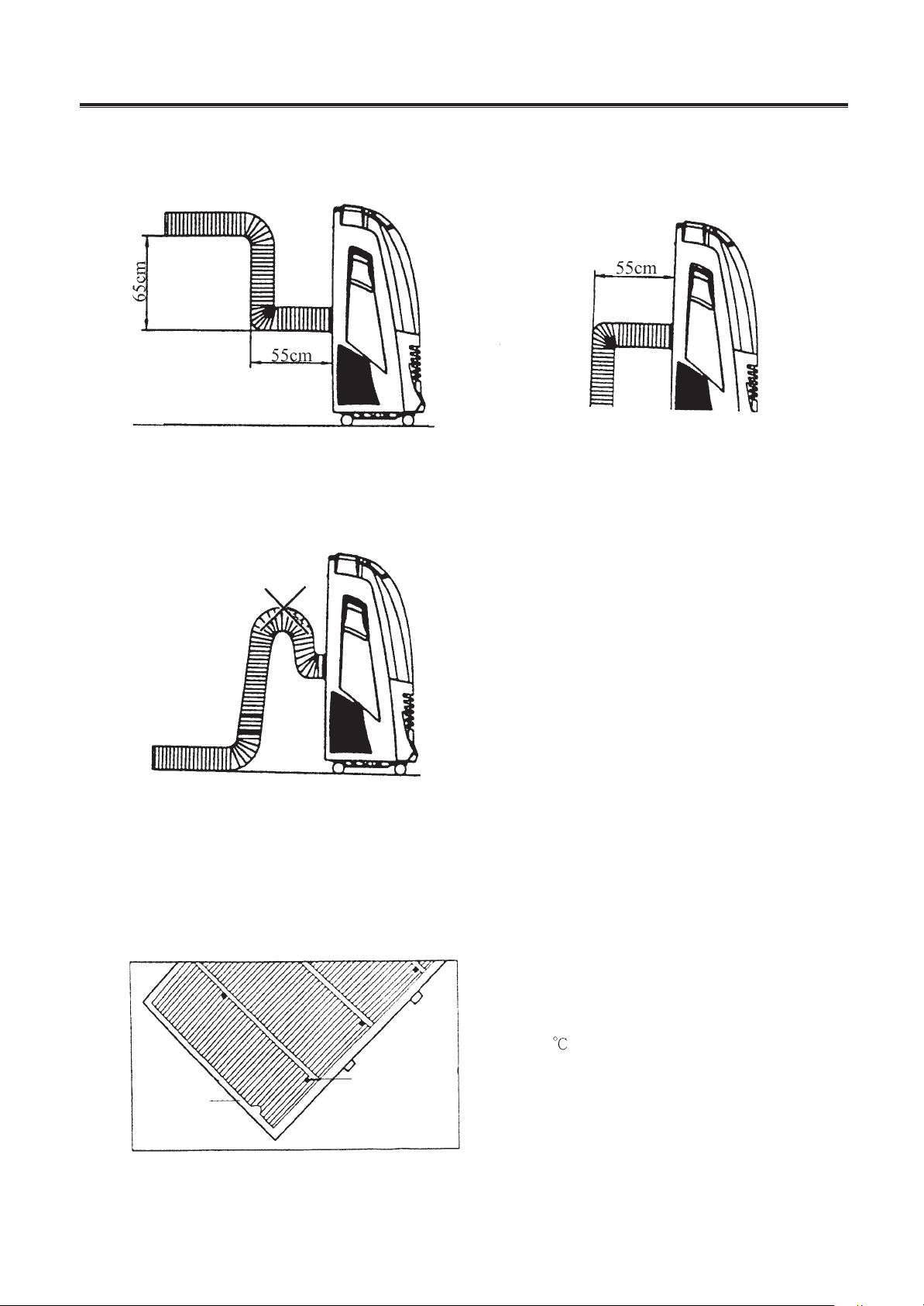
If the air exhaust requires bend, bend as shown as below.
The wrong mounting diagram (Air exhaust bend too large, easily cause malfunction).
2.AIR FILTER
If the air filter is blocked with a lot of dust, the air flow volume will reduce. Clean the filter once every two weeks.
Open the air filter
Open the air filter cover, then take off the air filter, Take
the air filter out of filter cover.
Clean
Wash the air filter by immersing it gently into warm
(about 40
) water with a neutral detergent, rinse the
filter of detergent and dry it thoroughly in a shaded place.
Mounting
Attach the filter to the filter cover with the attachment
hooks on the inside surface of the cover. Place the
hooks at the bottom of the filter cover into the holes in
the case, push it back into its orginal position.
hooks(10)
fiter cover
Mobile Air-conditioner
-
35
-
WATER DRAINAGE
When in cooling or dehumidifrying mode, the dew water will drain into the tank, When the tank gets full, the
indicator will flash, and the buzzer will sound eight times, LCD window shows error code “E4” at the same time the
unit will switch off.
As the step shown in the figure below. Take out the water tank, pour out the water inside the tank, then push it back
to its original position.
4.CAUTION
1. When in cooling or dehumidifying mode, do not take out the water tank, or the buzzer will sound and the unit will
switch off.
2. If you want to take out the tank before it is full of water, please stop the machine first, and wait for 3 minutes to
prevent the dew water from spilling into the unit.
3. There is a plastic pipe inside where the tank is placed. Do not remove the stopper while the unit is working because
the water is used for cooling the copper tube.
4. Put in the plug of drainage in water drainage method.
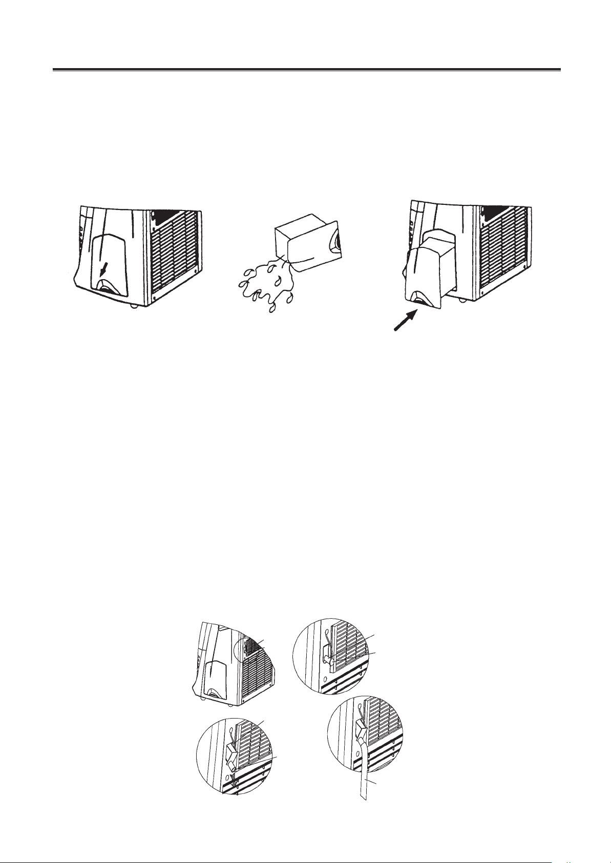
5.METHOD OF CONTINUOUS DRAINAGE
1. Push down the drainage and make it inclined, pull out the plug of drainage.
2. Don’t push down the drainage except for this application, otherwise it will leak.
Don’t make the continuous drainage clogged.
3. Hold the drainage, then insert the pipe into continuous drainage hole.
4. Drainage
- When draining out water, don’t press the drainage too forcefully.
- When draining out water, don’t make bend the pipe.
Step1
Step2
Step3
Mobile Air-conditioner
-
36
-
KY-32/K101 GP12-22L
GP12-12 KY-32U/11156
2.7 Circuit diagram
figure 2-4
Mobile Air-conditioner
-
37
-
GP12-12R KYD-32/K101
figure 2-5
Mobile Air-conditioner
-
38
-
2.8 PCB function manual
The 4 In 1 PCB function manual of the Mobile
1. Adequate models:
Mobile split Air-conditioner about 7,000Btu;
Mobile Air-conditioner about 7,000Btu;
Mobile split Air-conditioner about 9,000Btu;
Mobile Air-conditioner about 9,000Btu.
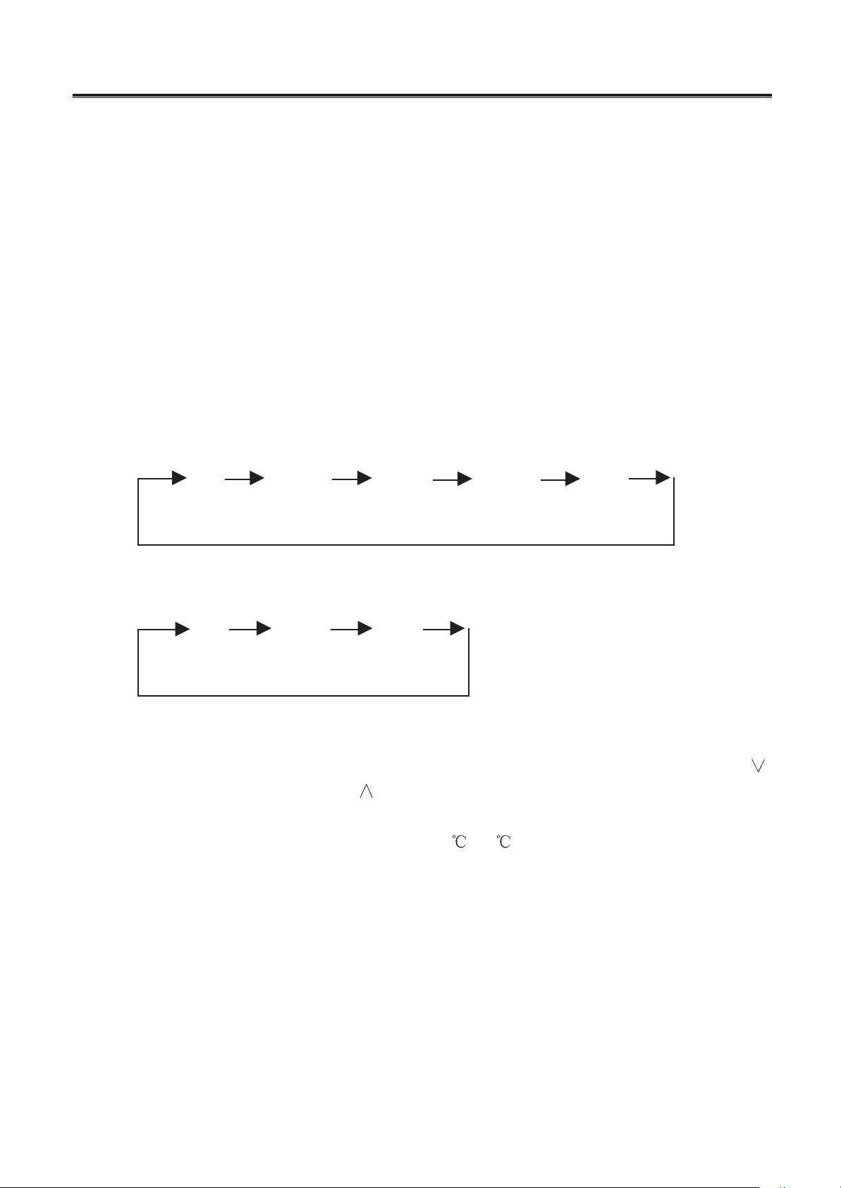
2. Running mode:
1) FAN; 2) COOL; 3) DRY; 4) HEAT; 5) AUTO.
3. Controlling modes:
1) Control panel; 2) Remote control.
4. The parameter to be input:
1) Analog quantity:
the ambient temperature of the indoor unit (shorten form is T
in
)
the temperature of deforesting (shorten form is T
de
)
the evaporator temperature of the indoor unit (shorten form is T
eva
)
the current of the compressor (shorten form is I
co
)
2) Switch quantity:
the switch of the higher water level
the switch of the lower water level
3) Controlled Input:
by the controlling panel;
by the remote control.
5. The parameter to be output:
1) Output quantity of transformer:
Indoor fan motor(3-speed)
Outdoor fan motor
Compressor
Reversing valve
Indoor & outdoor water pump
Sweeping fan motor
Electrical heater
2) Output quantity of LED:
the light of the running compressor (LED1 green)
The light of the beeper (LED2 red)
3) Others:
LCD
Mobile Air-conditioner
-
39
-
Beeper
6. The basal control modes:
1) Cooling mode:
If T
in
T
set
, cooling mode act, compressor and outdoor unit run, and indoor unit run in the
set speed;
If T
in
T
set
-1 , the unit will be stop from cooling mode, compressor and outdoor unit stop,
and indoor unit still run in the set speed;
If T
set
-1 T
in
T
set
, keep running in the old mode;
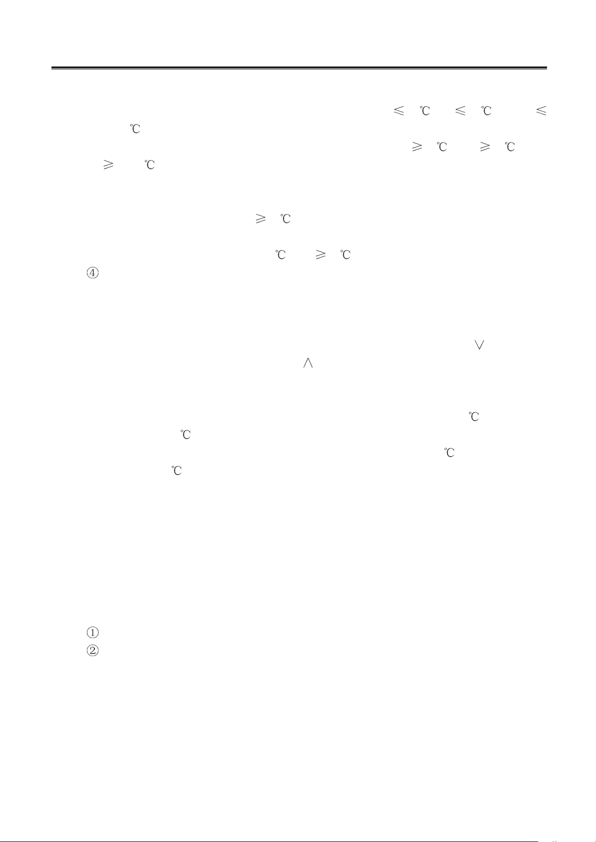
In the cooling mode, the range of T
set
is 16 ~30 , the initialize is 25
LCD: 9,000Btu series display “cooling”, ” the set fan speed”, “T
set
”
12,000Btu series display dynamic “the falling snow”, “the fan revolving in the set
speed”, ”the set fan speed”, and “T
set
”
The protecting functions:
Avoiding freezing:
Once the compressor works for 10min, when T
eva
-6 for over 8sec, the compressor
and the outdoor unit fan motor stop, the indoor unit fan motor run in the set speed. After the
compressor stops for 3min and T
eva
8 , everything runs in the old speed.)
Water pump control and the protection for the full water:
The indoor unit water pump will work when the lower water switch is close till the lower
water switch open for 2min.
The outdoor unit water pump will work after the indoor unit water pump works for 1min at
the 1
st
time, the outdoor unit water pump will stop when the compressor stop and it will
linkage with compressor in future.
When the higher water switch is close, the buzzer will alarm “click, click” 8 times, LCD
display the wrong code “E4” in the location of “setting temperature” (for the 9,000Btu series,
LED2 flash), it means the indoor unit water pump does not work and the unit stop till the
protection is canceled.
There is no water pump in the mobile air-conditioner, 1K resistance is used to short the
lower water pump. The higher water pump is close when the water tank is full, the buzzer
alarm “click, click” 8 times LCD display the wrong code “E4” in the location of “setting
temperature” (for the 9,000Btu series, LED2 flash), it means the indoor unit water pump
does not work and the unit stop till the protection is canceled.
The indoor unit and outdoor unit water pumps do not work in the mode of fanning and
heating.
Protecting the compressor:
The distance between 2 times running won’t less than 3min once the compressor work
and it will not stop by the changing of the temperature in the next 6min.
The compressor and the outdoor unit fan motor will stop when it is change from heating
mode to cooling mode.
Mobile Air-conditioner
-
40
-
The protection of overload current (low voltage protection):
When the I
co
13A for 3sec, the unit fan only (for 9,000Btu series, LED2 flash), LCD
display the wrong code E1, it means the I
co
is exceed the set current, compressor stop till
the fault is canceled in 3min.
2) Drying mode:
The indoor unit fan motor runs in the low speed, compressor and outdoor unit fan motor
run continually, the T
set
will not be displayed and changed.
For 9,000Btu series, it will be displayed the “drying” sign and “low speed”, for 12,000Btu
series, it will be displayed the picture of “water dripping” dynamic, the fan runs slowly.
The protection functions are same as the cooling mode, for 12,000Btu series, it will be
displayed the picture of “water is overflow” dynamic when the water tank is full.
3) Heating mode:
Mobile split air-conditioner (cooling & heating)
If T
in
T
set
+3 , heating mode act, reversing, compressor and outdoor unit fan motor run,
indoor unit fan motor runs in the set speed and the condition of avoiding the cold wind;
If T
in
=T
set
+4 , keep running in the old mode;
If T
in
T
set
+5 , compressor and outdoor unit fan motor stop, reserving valve is still
electric ,the indoor unit fan motor runs in the set speed and flow the rest heat;
In the heating mode, the 4-way valve will be electroless in 2min after the unit is turned off.
LCD: 9,000Btu series display the sign of heating, indoor unit fan motor speed and T
set
.
12,000Btu series display the sun light radiate outside dynamic, the fan runs in the set
speed and T
set
.
Electrical heater:
When the indoor unit fan motor run in middle or high speed, T
eva
49 , T
in
23 , and T
in
T
set
+1 , electrical heater work.
When indoor unit fan motor stop or run in low speed, either T
eva
57 , or T
in
26 ,or
T
in
T
set
+4 , electrical heater stop and restart till 2min later.
The protecting functions:
a. Protecting too high temperature of the compressor:
In heating mode, when T
eva
66 for 8sec, the outdoor unit fan motor stop, LCD
display “E3” in the location of T
set
; when T
eva
56 , outdoor unit fan resume to run, the
indoor unit fan motor run in the set speed and LCD resume too.
b. The conditions of avoiding cold wind:
In heating mode, either T
eva
28 or the compressor running for over 10sec, the
indoor unit fan motor run in the set speed.
c. The conditions of flowing hot wind:
Once the compressor stop, the indoor unit fan motor runs in low speed and will stop
too in 30sec.
d. The conditions of beginning defrosting:
Mobile Air-conditioner
-
41
-
After the unit continue heating for 45min and if T
de
-8 , the defrosting mode act, the
reversal valve, the indoor and outdoor unit stop but the compressor.
If there is electrical heater in the unit, then it will be stop first and the reversal valve, the
indoor and outdoor unit stop in 1min.
e. The conditions of stopping defrosting:
After the unit continue defrosting for 10min or if T
de
10 , the defrosting stop, the
reversal valve, the outdoor unit run, and the indoor unit fan motor will run in the condition
of avoiding the cold wind.
f. The protection of overload current is same as cooling mode
g. The delay of compressor
The distance between 2 times running won’t less than 3min once the compressor
work and it will not stop by the changing of the temperature in the next 6min.
The compressor and the outdoor unit fan motor will stop for 3min when it is change
from heating mode to cooling mode. The indoor unit fan motor run in the set speed the
mode and avoiding the cold win and.
12,000Btu series mobile air-conditioner whit the mode cooling & heating
If T
in
T
set
+3 , heating mode act, reversing, compressor, outdoor unit fan motor and
electrical heater run, indoor unit fan motor runs in the set speed ;
If T
in
=T
set
+4 , keep running in the old mode;
If T
in
T
set
+5 , electrical heater stop and the indoor unit fan motor will stop in 15sec.
4) Fanning mode:
The indoor unit fan motor has 3 speeds which are high, middle and low, it will bot display
the T
set
and can not be changed.
9,000Btu series display the high, middle and low speed sign by the speed of indoor unit
fan motor;
12,000Btu series display the fanning sign same as the indoor unit fan.
5) Auto functions:
The unit run depending on the T
in
.
If T
in
26 , cooling mode act, T
in
is 26 .
If 26 T
in
20 , drying mode act, indoor unit fan motor run in low speed, compres-
sor and outdoor unit fan motor run continually.
If T
in
20 , the different unit run different mode.
a. Air-conditioner with cooling & heating mode run heating mode, T
set
is 20 , if T
in
24 , stop heating.
Electrical heating run depending the conditions following:
If T
in
T
set
, heating mode act, reversal valve, compressor and outdoor unit fan motor run
together, indoor unit fan motor run in the set speed and avoiding the cold wind.
If T
set
T
in
T
set
+2 , the unit run in old mode.
If T
in
T
set
+2 , compressor, outdoor unit fan motor stop together, reversal valve is
Mobile Air-conditioner
-
42
-
electrical, indoor unit fan motor run in the mode of flowing the hot wind.
If indoor unit fan motor run in middle or high speed, T
eva
49 , T
set
23 , and T
in
T
set
-2 , electrical heater act.
If either indoor unit fan motor stop or run in low speed, or T
eva
57 , or T
in
26 , or T
in
T
set
+1 , electrical heater stop and restart in 2min.
The protecting function of auto-heating mode is same as heating mode.
b. 12,000Btu series cooling only mobile air-conditioner and mobile split air-conditioner
run the fanning mode, if T
in
24 , stop fanning.
c. 12,000Btu series cooling & heating mobile air-conditioner run the heating mode same
as the heating mode, T
set
is 20
, if T
in
24 , heating mode stop.
LCD: It display the corresponding code of the running mode and the “AUTO” mark.
7. Other control:
1) Timer:
Set timer to “OFF” when the unit is working and set time to “ON” when the unit is stop, the
range is 2~4h, the set time will decrease 0.5h once pressing the button “ ”, and it will
increase 0.5h once pressing the button “
”. The buttons have the function of canceling
“set timer”.
2) Sleep:
If it is cooling or drying, in 1hour of the beginning, the T
set
will be increased 1 , and it will be
increased more 1
in the later 2hour, then the unit runs in this temperature.
If it is heating, in 1hour of the beginning, the T
set
will be decreased 1 , and it will be de-
creased more 1
in the later 2hour, then the unit runs in this temperature.
LCD display the “SLEEP” mark and for 12,000Btu series, it display the twinkle stars.
3) Choosing the models:
Models are decided by the state of the chi’ feet.
21 foot is 12,000Btu(upwards)/9,000Btu(downwards)
22 foot is Celsius(upwards)/Fahrenheit(downwards)
20 foot is Cooling &heating(upwards)/cooling only(downwards)
19 foot is Mobile split(upwards)/Mobile(downwards)
4) LED of 12,000Btu series:
The light of compressor running is green and it is light when the compressor is working;
The light of protecting is red. It will twinkle when the water tank is full or there is a overload
in compressor, the frequency of twinkling is 1Hz.
5) Controlling the sweep motor:
9,000Btu series’ sweep motor is controlled by the button-sweeping, when the button is
pressed once, sweep motor run and will stop when it is pressed again.
12,000Btu series’ sweeping motor revolve 85° anticlockwise to open the air let at the be-
ginning of the unit running and it revolve clockwise to close the air let when the unit is stop.
6) Testing functions:
Mobile Air-conditioner
-
43
-
Turn on the unit when the FAST is short circuit, LCD is light for 3sec, press the “mode”
button, there is no delay protection for compressor and others functions are all same as the
normal state.
Turn on the unit when the FAST is shorten, if the sensor is open or short circuit, LCD display
the following mark in the location of T
set
:
Sensor of indoor unit is open or short, display “F0”
Sensor of evaporator is open or short, display “F1”
Sensor of deforesting is open or short, display “F2”
7) It can be used in the range of AC220V±10%.
8) There is a short circuit protecting in the circuit.
8. Buttons on the control panel:
1) ON/OFF button;
2) MODE button;
3) Fan speed button;
4) Timer button;
The range of changing set time is 0.5~24h, the set time will be canceled when press “
”
when set time is 0.5h or press “
” when set time is 24h.
5) Temperature button;
The range of changing set temperature is 16 ~30 .
6) Sleeping button:
7) Sweeping button (just for 9,000Btu series).
9. Design of remote control:
Y602(Chinese) and Y612A(English, Celsius)/Y612AF(English, Fahrenheit) are be used to
control 12,000Btu series of mobile, mobile and split air-conditioner.
Low Middle High
Fan Cooling Drying Heating Auto

TECHNICAL SERVICE MANUAL
Mobile Air-conditioner Series
GREE ELECTRIC APPLIANCES, INC. OF ZHUHAI
Jinji West Rd. Qianshan Zhuhai
Guangdong China

Introduction
In this technical service manual, you will find rich references to Mobile Air-conditioner
Series products, including photos, technical specifications, explosive views, spare parts lists
and circuit diagrams. Service people and engineers of Gree’s customers and distributors
would find it a very handy source of technical information of our products.
Technical Support Department
GREE ELECTRIC APPLIANCES, INC. OF ZHUHAI
Nov. 2002
Editor In Chief: Chen Jianmin
Compiler: Chen Zhian Ouyang Jun Tian Guoku
Wang Min Yang Rong Cao Xuan Jia Tianwei
Proofreader: Li Jing Zhang Tao Kou Bin Liao Lei Li Guangxiang Zhou Yuexia
Designer of Cover: Li Jiesheng Sheng Zhiguo

CONTENTS
1.Mobile Air-conditioner series (KY-20).....................................................................................1
1.1 Summary ......................................................................................................................... 1
1.2 Technical specifications ................................................................................................... 3
1.3 Outlines and dimensions..................................................................................................9
1.4 Explosive view ...............................................................................................................10
1.5 Spare parts list...............................................................................................................11
1.6 Installation guide ............................................................................................................16
1.7 Circuit diagram ..............................................................................................................19
1.8 PCB function manual .....................................................................................................22
2.Mobile Air-conditioner series (KY-32)...................................................................................25
2.1 Summary .......................................................................................................................25
2.2 Technical specifications .................................................................................................27
2.3 Outlines and dimensions................................................................................................29
2.4 Explosive view ...............................................................................................................30
2.5 Spare parts list...............................................................................................................31
2.6 Installation guide ............................................................................................................33
2.7 Circuit diagram ..............................................................................................................36
2.8 PCB function manual .....................................................................................................38