Loading ...
Loading ...
Loading ...
EN
W415-4155 / - / 05.10.23
19
Hard-Wiring Connection
If it is necessary to hard-wire this appliance, a qualifi ed electrician must remove the cord connection and wire
the appliance directly to the household wiring. The dedicated circuit and power supply breaker must be rated for
120V, 15 amps.
The appliance must be electrically connected and grounded in accordance with local codes. In the absence
of local codes, use the current CSA C22.1 Canadian Electrical Code in Canada or the current ANSI/NFPA 70
National Electrical Code in the United States.
• Turn off the appliance completely and let it cool down before servicing. Only a qualifi ed service person should
service and repair this electric appliance.
!
WARNING
4.0 electrical information
4.1 hard-wiring installation
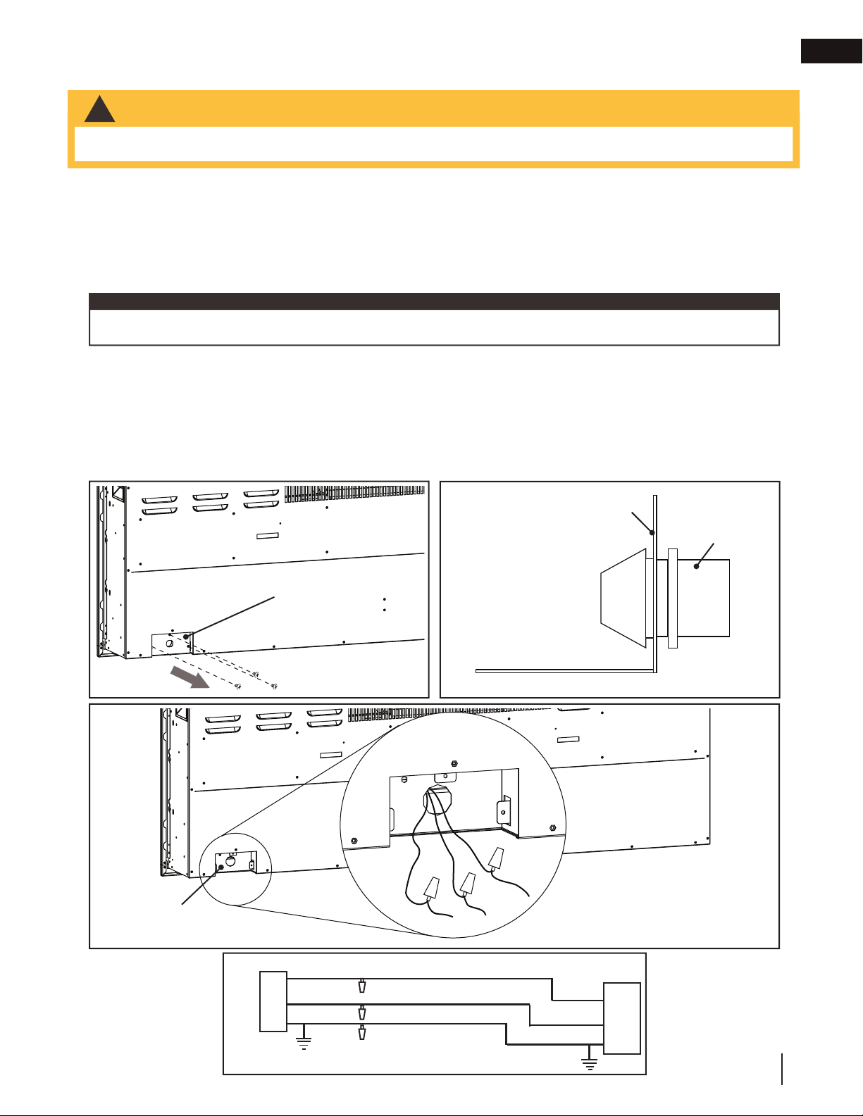
There are 3 wires from the appliance junction: white (neutral), black (power L1), and green (ground) that connect
to 120V power supply (break panel). See below.
note:
A. Remove the 3 securing screws from the junction box cover plate, located on the bottom left hand side of
the appliance (Fig. 4-1).
B. Install the strain relief to the junction box cover plate (located in hardware bag) (Fig. 4-2).
C. Separate the black, white, and green wires that have the wire nuts on them.
D. Remove all the wire nuts. Connect the green wire (G) to the supply ground wire, the white wire (N) to the
supply Neutral wire, and the black wire (L) to the supply L1 wire. (Fig. 4-3).
E. Resecure the junction box cover plate using the 3 screws previously removed in step A.
BLACK
WHITE
BLACK
WHITE
4
6
1
1
-
:
1
0
8
&
3
+
6
/
$
5
*
0
/
'
*
3
&
1
-
"
$
&
GREEN
GREEN
(L1)
(N)
(G)
WIRE NUT
Fig. 4-1
Junction Box
Cover Plate
Junction Box
Cover Plate
Strain Relief
Inside
Appliance
Outside
Appliance
Fig. 4-2
WHITE
BLACK
GREEN
Junction Box
Green, white, and
black wires: connect
to 120V power supply.
Fig. 4-3
Loading ...
Loading ...
Loading ...