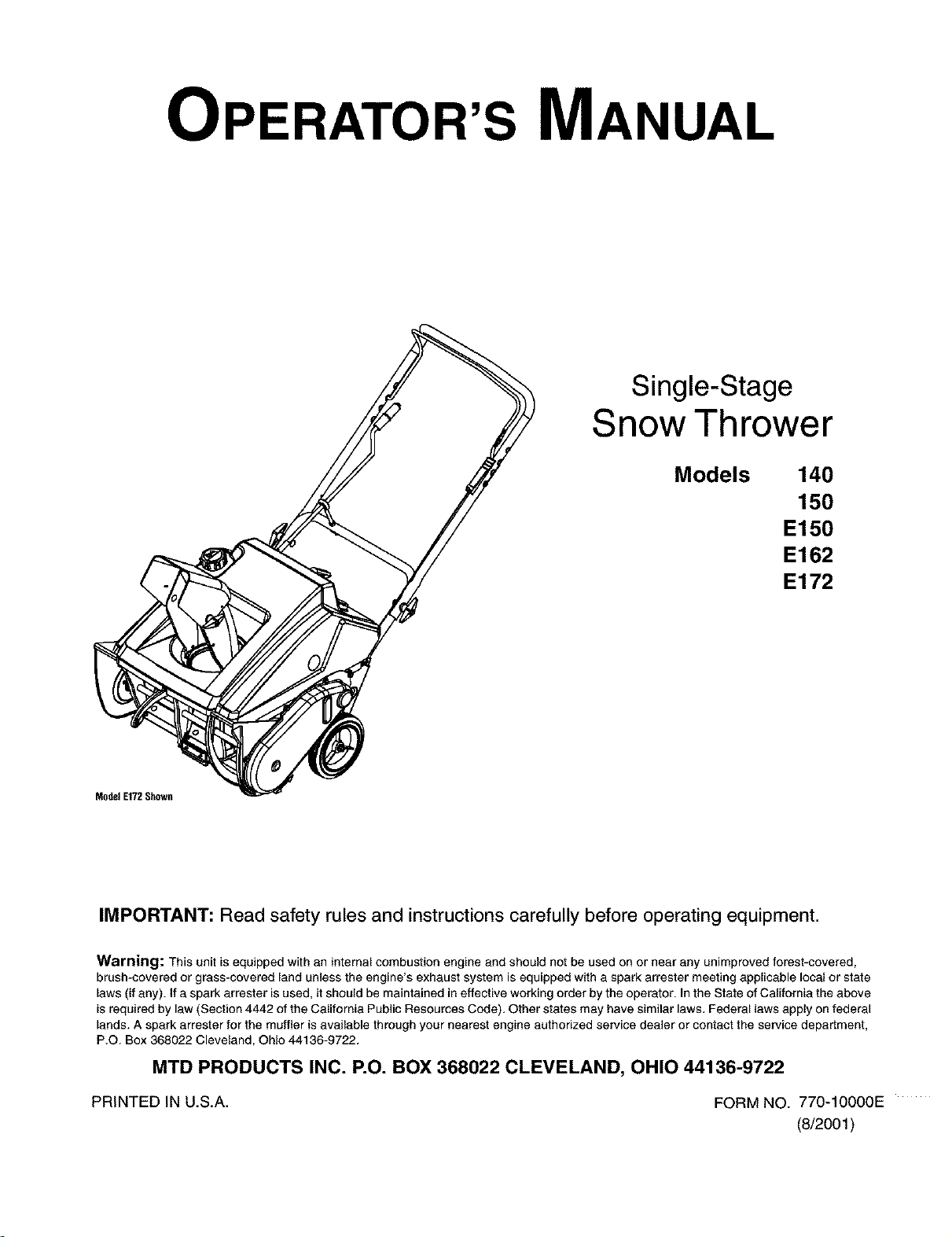
OPERATOR'S MANUAL
Single-Stage
Snow Thrower
Models 140
150
E150
E162
E172
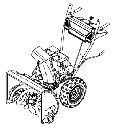
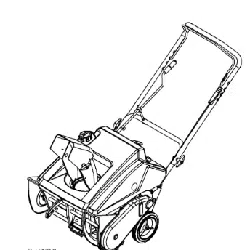
ModelE172Shown
IMPORTANT: Read safety rules and instructions carefully before operating equipment.
Warning: This unit isequipped with an internal combustion engine and should not be used on or near any unimproved forest-covered,
brush-covered or grass-covered land unless the engine's exhaust system is equipped with a spark arrester meeting applicable local or state
laws (if any). If a spark arrester isused, it should be maintained in effective working order by the operator. In the State of California the above
is required by law (Section 4442 of the California Public Resources Code). Other states may have similar laws. Federal laws apply on federal
lands. A spark arrester far the muffler is available through your nearest engine authorized service dealer or contact the service department,
P.O. Box 368022 Cleveland, Ohio 44136-9722.
MTD PRODUCTS INC. P.O. BOX 368022 CLEVELAND, OHIO 44136-9722
PRINTED IN U.S.A.
FORM NO. 770-10000E
(8/2001 )
TABLEOFCONTENTS
Content Page
Important Safe Operation Practices ......................................................................................... 3
Assembling Your Snow Thrower .............................................................................................. 5
Know Your Snow Thrower ........................................................................................................ 7
Operating Your Snow Thrower ................................................................................................. 8
Making Adjustments ................................................................................................................. 9
Maintaining Your Snow Thrower .............................................................................................. 10
Off-Season Storage ................................................................................................................. 11
Troubleshooting ....................................................................................................................... 11
Accessories & Kits ................................................................................................................... 12
Parts List .................................................................................................................................. 14
FINDINGMODELNUMBER
This Operator's Manual is an important part of your new snow thrower. It will help you to assemble, prepare and
maintain the unit for best performance. Please read and understand what it says.
Before you start assembling your new snow thrower, please locate the model plate on the
equipment and copy the informationfrom itin the space provided below. The information on the
model plate is very important if you need help from our Customer Support Department or an
authorized dealer.
You can locate the model number by standing behind the unit in the operating position and looking down at
the dash panel. A sample model plate is explained below. For future reference, please copy the model
number and the serial number of the equipment in the space below.
(Model Number) (Serial Number)
LEVELAND, OHIO 441_
Copy the model number here:
Copy the serial number here:
ENGINEINFORMATION
The engine manufacturer isresponsible for all engine-related issues with regards to performance, power-rating,
specifications, warranty and service. Please refer to the engine manufacturer's Owner's/Operator's Manual packed
separately with your unit for more information.
CALLINGCUSTOMERSUPPORT
If you have difficulty assembling this product or have any questions regarding the controls, operation or
maintenance of this unit, please call the Customer Support Department.
Call 1- (330) 220-4MTD (4683) or 1- (800) 800-7310 to reach a Customer Support representative.
Please have your unit's model number and serial number ready when you call. See previous section
to locate this information. You will be asked to enter the serial number in order to process your call.
SECTION1: IMPORTANTSAFEOPERATIONPRACTICES
WARNING: This symbol points out important safety instructions which, if not followed, could endanger the
personal safety and/or property of yourself and others. Read and follow all instructions in this manual before
attempting to operate this machine. Failure to comply with these instructions may result in personal injury. When you
see this symbol--heed its warning.
WARNING: Engine Exhaust, some of its constituents, and certain vehicle components contain or emit chemicals
known to State of California to cause cancer and birth defects or other reproductive harm.
DANGER: This machine was built to be operated according to the rules for safe operation in this manual. As with
any type of power equipment, carelessness or error on the part of the operator can result in serious injury. This
machine is capable of amputating hands and feet and throwing objects. Failure to observe the following safety
instructions could result in serious injury or death.
Training
1. Read, understand, and follow all instructions on the
machine and in the manual(s) before attempting to
assemble and operate. Keep this manual in a safe place
for future and regular reference and for ordering
replacement parts.
2. Be familiar with all controls and their proper operation.
Know how to stop the machine and disengage them
quickly.
3. Never allow children under 14 years old to operate this
machine. Children 14 years old and over should read and
understand the operation instructions and safety rules in
this manual and should be trained and supervised by a
parent.
4. Never allow adults to operate this machine without
proper instruction.
5. Thrown objects can cause serious personal injury. Plan
your snow throwing pattern to avoid discharge of material
toward roads, bystanders and the like.
6. Keep bystanders, helpers, pets and children at least 75
feet from the machine while it is in operation. Stop
machine if anyone enters the area.
7. Exercise caution to avoid slipping or falling, especially
when operating in reverse.
Preparation
1. Thoroughly inspect the area where the equipment is to
be used. Remove all door mats, newspapers, sleds,
boards, wires and other foreign objects which could be
tripped over or thrown by the augedimpeller.
2. Always wear safety glasses or eye shields during
operation and while performing an adjustment or repair to
protect your eyes. Thrown objects which ricochet can
cause serious injury to the eyes.
3. Do not operate without wearing adequate winter outer
garments. Do not wear jewelry, long scarves or other
loose clothing which could become entangled in moving
parts. Wear footwear which will improve footing on
slippery surfaces.
4. Use a grounded three wire extension cord and receptacle
for all units with electric start engines.
5. Adjust collector housing height to clear gravel or crushed
rock surfaces.
6. Disengage all clutch levers before starting the engine.
7. Never attempt to make any adjustments while engine is
running, except where specifically recommended in the
operator's manual.
8. Let engine and machine adjust to outdoor temperature
before starting to clear snow.
9. To avoid personal injury or property damage use extreme
care in handling gasoline. Gasoline is extremely
flammable and the vapors are explosive. Serious
personal injury can occur when gasoline is spilled on
yourself or your clothes which can ignite. Wash your skin
and change clothes immediately.
a. Use only an approved gasoline container.
b. Extinguish all cigarettes, cigars, pipes and other
sources of ignition.
c. Never fuel machine indoors.
d. Never remove gas cap or add fuel while the
engine is hot or running.
e. Allow engine to cool at least two minutes before
refueling.
f. Never over fill fuel tank. Fill tank to no more than
Y_inch below bottom of filler neck to provide space
for fuel expansion.
g. Replace gasoline cap and tighten securely.
h. If gasoline is spilled, wipe it off the engine and
equipment. Move machine to another area. Wait 5
minutes before starting the engine.
i. Never store the machine or fuel container inside
where there is an open flame, spark or pilot light
(e.g. furnace, water heater, space heater, clothes
dryer etc.).
j. Allow machine to cool at least 5 minutes before
storing.
Operation
1. DO not put hands or feet near rotating parts, in the auger/
impeller housing or discharge chute. Contact with the
rotating parts can amputate hands and feet.
2. The augedimpeller clutch lever is a safety device. Never
bypass its operation. Doing so, makes the machine
unsafe and may cause personal injury.
3. The clutch levers must operate easily in both directions
and automatically return to the disengaged position when
released.
4. Never operate with a missing or damaged discharge
chute. Keep all safety devices in place and working.
5. Never run an engine indoors or in a poorly ventilated
area. Engine exhaust contains carbon monoxide, an
odorless and deadly gas.
6. Do not operate machine while under the influence of
alcohol or drugs.
7. Mufflerandenginebecomehotandcancauseabum.Do
nottouch.
8. Exerciseextremecautionwhenoperatingonorcrossing
gravelsurfaces.Stayalertforhiddenhazardsortraffic.
9. Exercisecautionwhenchangingdirectionandwhile
operatingonslopes.
10.Planyoursnowthrowingpatterntoavoiddischarge
towardswindows,walls,carsetc.Toavoidproperty
damageorpersonalinjurycausedbyaricochet.
11.Neverdirectdischargeatchildren,bystandersandpets
orallowanyoneinfrontofthemachine.
12.Donotoverloadmachinecapacitybyattemptingtoclear
snowattoofastofarate.
13.Neveroperatethismachinewithoutgoodvisibilityor
light.Alwaysbesureofyourfootingandkeepafirmhold
onthehandles.Walk,neverrun.
14.Disengagepowertotheauger/impe{lerwhen
transportingornotinuse.
15.Neveroperatemachineathightransportspeedson
slipperysurfaces.Lookdownandbehindandusecare
wheninreverse.
16.Ifthemachineshouldstarttovibrateabnormally,stopthe
engine,disconnectthesparkplugandgrounditagainst
theengine.Inspectthoroughlyfordamage.Repairany
damagebeforestartingandoperating.
17.Disengageallclutch{oversandstopengine before you
leave the operating position (behind the handles). Wait
until the augedimpeller comes to a complete stop before
unclogging the discharge chute, making any
adjustments, or inspections.
18. Never put your hand in the discharge or collector
openings. Always use aclearing tool to unclog the
discharge opening.
19. Use only attachments and accessories approved by the
manufacturer (e.g. wheel weights, tire chains, cabs etc.).
20. Ifsituations occur which are not covered in this manual,
use care and good judgment. Contact your dealer or
telephone 1-800-800-7310 for assistance and the name
of your nearest servicing dealer.
MaintenanceAndStorage
1. Never tamper with safety devices. Check their proper
operation regularly.
2. Disengage all clutch levers and stop engine. Wait until
the auger/impeller come to a complete stop. Disconnect
the spark plug wire and ground against the engine to
prevent unintended starting before cleaning, repairing, or
inspecting.
3. Check bolts, and screws for proper tightness at frequent
intervals to keep the machine in safe working condition.
Also, visually inspect machine for any damage.
4. Do not change the engine governor setting or over-speed
the engine. The governor controls the maximum safe
operating speed of the engine.
5. Snow thrower shave plates and skid shoes are subject to
wear and damage. For your safety protection, frequently
check all components and replace with original
equipment manufacturer's (O.E.M.) parts only. "Use of
parts which do not meet the original equipment
specifications may lead to improper performance and
compromise safety!"
6. Check clutch controls periodically to verify they engage
and disengage properly and adjust, if necessary. Refer to
the adjustment section in this operator's manual for
instructions.
7. Maintain or replace safety and instruction labels, as
necessary.
8. Observe proper disposal laws and regulations for gas,
oil, etc. to protect the environment.
9. Prior to storing, run machine a few minutes to clear snow
from machine and prevent freeze up of auger/impeller.
10. Never store the machine or fuel container inside where
there is an open flame, spark or pilot light such as a water
heater, furnace, clothes dryer etc.
11. Always refer to the operator's manual for proper
instructions on off-season storage.
YourResponsibility:
Restrict the use of this power machine to persons who
read, understand and follow the warnings and
instructions in this manual and on the machine.
SECTION2: ASSEMBLINGYOURSNOWTHROWER
NOTE: This Operator's Manual covers several models.
Snow thrower features vary by model. Not all
features discussed in this manual are applicable to all
snow thrower models.
ContentsofCarton
Before beginning installation, remove all parts from the
carton and compare them to Figure 1. Carton contents
are listed below with part numbers in parentheses.
• Two Ignition Keys (725-0201,725-1341B t)
t An ignitionkey with a plasticcover is includedwith
select models only. Two standard ignition keysare
included with all other models.
OnModelsSoEquipped:
• Extended Chute Directional Control Assembly
(747-0737, 720-0201A & 726-0100)
• One Cotter Pin (714-0507)
• One Saddle Washer (736-0415)
• Two Hex Nuts (712-3010)
One Eye Bolt (747-0697) w/Grommet (735-0234)
Ignition Key w/Plastic Cover t
Standard Ignition Key
/ _ Cotter Pin
-,_ Saddle Washer
O O "_ Hex Nuts
_-- Eye Bolt
Extended Chute
Directional Control Assembly
Figure 1
NOTE: All references to left or right side of the snow
thrower is from the operating position only.
,_ WARNING: Disconnect the spark plug wire
and ground it against the engine to prevent
unintended starting.
Positioningthe UpperHandle
• Remove packing material, if present, and loosen
the wing knobs found on each side of the handle.
• Making sure not to pinch or crimp the cable in the
process, pivot the upper handle into the operating
position as illustrated in Figure 2 until itclicks into
place.
Wing
Wing Knob
Figure 2
Tighten the wing knobs to secure the handle in
place.
AttachingtheControlCable
The control cable may already be attached to the
control handle. If it's not, complete the following steps
to attach it to the snow thrower housing.
• Route the control cable over the crossbar where
the lower handle meets the upper handle.
• Pivot the control handle forward and insert the end
of the control cable into the bottom hole in the
control handle, from the outside to the inside, as
shown in Figure 3.
Control Handle
/-
Upper Hole
End of Cable
In Bottom Hole
Control Housinc
Plastic Fitting
Figure 3
• Push the plastic fitting intothe control housing until
it clicks in place
NOTE:The upper hole in the control handle provides
for adjustment in belt and cable tension. Refer to page
9 of this manual for instructions.
InstallingtheChuteDirectionalControl's
EyeBolt(onmodelssoequipped)
To install the upper crank of the chute directional
control, proceed as follows:
• Thread one of the hex nuts (they are
interchangeable) included in the snow thrower's
hardware pack all the way onto the eye bolt.
• Insert the eye bolt into the hole found in the lower
handle's crossbar. See Figure 4.
• Fasten the eye bolt to the crossbar with the saddle
washer (cupped side UP) and the other hex nut as
illustrated in Figure 4. Do NOT tighten at this time.
InstallingtheExtendedChute
DirectionalControl(onmodelssoequipped)
• Insert the chute directional control through the
eyebolt and into the coupler found in the top right
area of the snow thrower's shroud. See Figure 5.
• Rotate the chute directional control to align the hole
in the coupler with the hole in the chute directional
control, and insert the cotter pin through both holes.
Bend the ends of cotter pin in opposite directions to
secure it in place. See Figure 5.
• Thread the eye bolt's lower hex nut upward or
downward to adjust the height of the eye bolt so
that the chute directional control does not bind in
the coupler when operated.
• Fininsh by threading the upper hex nut downward
against the crossbar and tightening securely.
Assemblingthe DischargeChute
For shipping reasons, the snow thrower has been
packaged with the upper chute pivoted all the way
down. To pivot it upward, proceed as follows:
• Turn the chute directional control until the chute
opening is facing straight ahead.
• Remove the wing knob, flat washer and carriage
bolt from the upper chute. See Figure 6.
• Pivot the upper chute upward over the lip on the
lower chute so that there is NO gap between the
upper chute and the lower chute. See Figure 6.
• Resecure with the hardware just removed.
Eye Bolt
Cross Bar
Figure 4
CiiltllDirection al Controt
Co.erPin/ /
- Eye Bolt
Figure 5
Carriage Bolt Flat
Washer
Lower Chute Lip
Upper Chute
Figure 6
SECTION3: KNOWYOURSNOWTHROWER
Discharge Chute
Shave Plate
Auger
Sp_lark
ug
Cover
Starter
Choke Lever
Upper Handle
Cap
Control Handle
Electric
Starter
Button
!_ (if So Equipped)
Chute Directional Control
Electric Starter Plug
(if So Equipped)
IMPORTANT: This unit runs on a mixture of gasoline
and oil. Do NOT operate the snow thrower without first
reading the Tecumseh Engines operator's manual for
instructions regarding proper fuel and engine oil.
ChokeLever
(OFF 0iICHQKE li )ON I
Activating the choke control closes the choke plate on
the carburetor and aids in starting the engine. Refer to
the engine manual packed with the snow thrower for
more detailed instructions regarding the choke.
Primer
Depressing the primer forces fuel
directly into the engine's carburetor to
@
aid in cold-weather starting. Refer to
the engine manual packed with the
snow thrower for more detailed
pOliO FOR A
instructions regarding the primer. =oLD=.=,.=
IgnitionKey
The ignitionkey must be present /_)('_'_'___
and placed in the "ON" position for
the engine to start.
Starter Handle
The starter handle is used to manually start the engine.
StoppingEngine
• Turn ignition key to OFF position and remove it
from the snow thrower.
ElectricStarter Button(If so equipped)
Pressing the electric starter button engages the
engine's electric starter when plugged into a 120V
power source
ElectricStarter Plug (If so equipped)
Requires use of a two-prong outdoor extension cord
(packed with the snow thrower) and a 120V power
source/wall outlet.
SparkPlugCover
Remove the spark plug cover to access the engine's
spark plug located beneath it.
ChuteDirectionalControl
Located on right side of dash panel, the chute
directional control determines the direction that snow
will be discharged. Crank it clockwise to discharge
snow to the left; counterclockwise to discharge snow to
the right.
Auger
When engaged, the augers rotation picks up snow that
enters the auger housing and throws itout the
discharge chute. The rubber paddles on the augers
also aid in propelling the snow thrower as they come in
contact with the pavement.
AugerControlHandle
Located on the upper handle, the auger control handle
is used to engage and disengage drive to the auger.
Squeeze the control handle against the upper handle to
engage the auger; release it to disengage.
DischargeChute
The pitch of the discharge chute controls the angle at
which the snow is thrown. Loosen the wing knob on the
side of the discharge chute before pivoting the
discharge chute upward or downward. Retighten the
knob once the desired position has been achieved.
ShavePlate
The shave plate scrapes along the pavement as the
snow thrower is propelled, allowing the snow close to
the pavement's surface to be discharged.
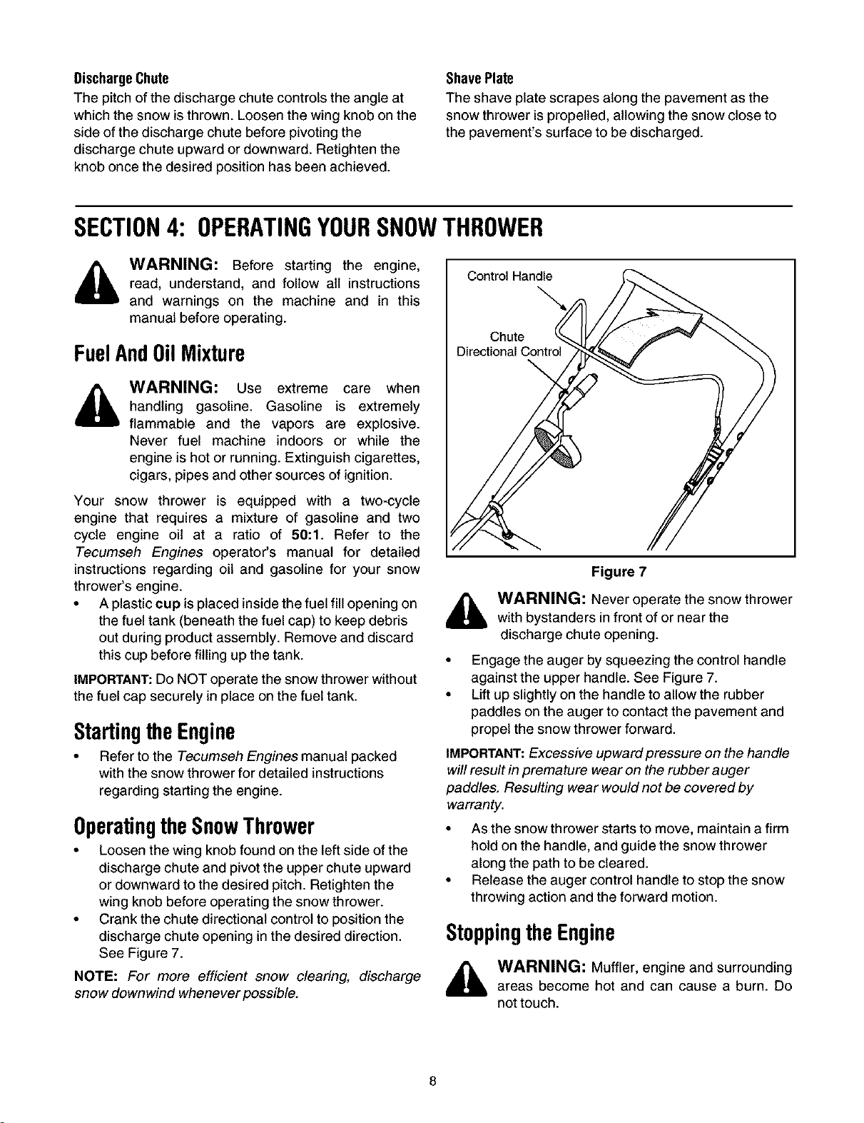
SECTION4: OPERATINGYOURSNOWTHROWER
WARNING: Before starting the engine,
read, understand, and follow all instructions
and warnings on the machine and in this
manual before operating.
FuelAndOilMixture
WARNING: Use extreme care when
handling gasoline. Gasoline is extremely
flammable and the vapors are explosive.
Never fuel machine indoors or while the
engine is hot or running. Extinguish cigarettes,
cigars, pipes and other sources of ignition.
Your snow thrower is equipped with a two-cycle
engine that requires a mixture of gasoline and two
cycle engine oil at a ratio of 50:1. Refer to the
Tecumseh Engines operator's manual for detailed
instructions regarding oil and gasoline for your snow
thrower's engine.
• A plastic cup is placed inside the fuel fill opening on
the fuel tank (beneath the fuel cap) to keep debris
out during product assembly. Remove and discard
this cup before filling up the tank.
IMPORTANT: Do NOT operate the snow thrower without
the fuel cap securely in place on the fuel tank.
StartingtheEngine
• Refer to the Tecumseh Engines manual packed
with the snow thrower for detailed instructions
regarding starting the engine.
OperatingtheSnowThrower
• Loosen the wing knob found on the left side of the
discharge chute and pivot the upper chute upward
or downward to the desired pitch. Retighten the
wing knob before operating the snow thrower.
• Crank the chute directional control to position the
discharge chute opening in the desired direction.
See Figure 7.
NOTE: For more efficient snow clearing, discharge
snow downwind whenever possible.
Control Handle
Chute
Figure 7
,_ WARNING: Never operate the snow thrower
with bystanders infront of or near the
discharge chute opening.
• Engage the auger by squeezing the control handle
against the upper handle. See Figure 7.
• Lift up slightly on the handle to allow the rubber
paddles on the auger to contact the pavement and
propel the snow thrower forward.
IMPORTANT: Excessive upward pressure on the handle
will result in premature wear on the rubber auger
paddles. Resulting wear would not be covered by
warranty.
• As the snow thrower starts to move, maintain a firm
hold on the handle, and guide the snow thrower
along the path to be cleared.
• Release the auger control handle to stop the snow
throwing action and the forward motion.
StoppingtheEngine
_ WARNING: Muffler, engine and surrounding
areas become hot and can cause a burn. Do
not touch.
Afterclearingsnow,allowtheenginetorunforan
extrafewminutesbeforestoringtohelpdryany
moistureontheengine.
Tostoptheengine:Turntheignitionkey
counterclockwisetotheOFFposition.Referto
IgnitionKeyon page 7. Remove the key form the
snow thrower's ignition switch before storing.
IMPORTANT: Keep the ignition key in a safe place. The
engine can not be started without it.
• Wipe all the snow and any moisture which has
formed, from the unit.
• Move the choke lever back and forth several times.
SECTION5: MAKINGADJUSTMENTS
WARNING: NEVER attempt to make any
adjustments while the engine is running, except
where specified in the operator's manual.
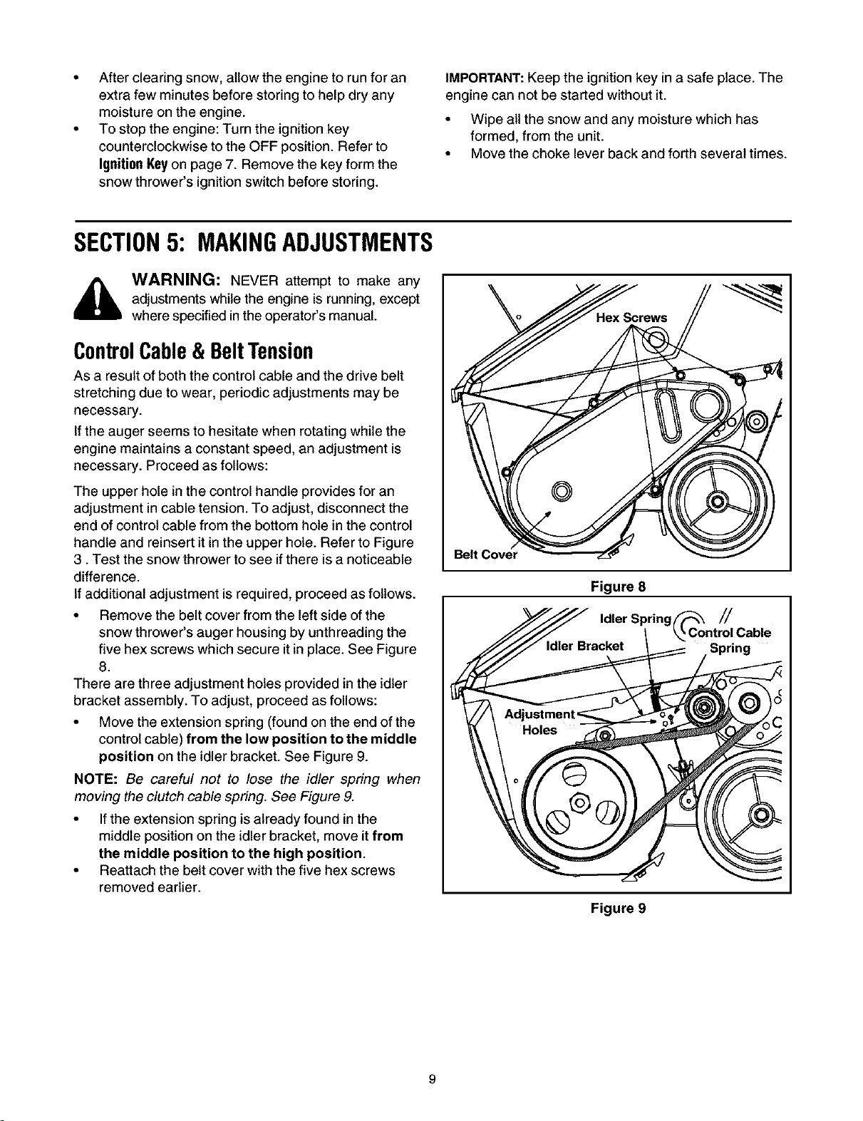
ControlCable& BeltTension
As a result of both the control cable and the drive belt
stretching due to wear, periodic adjustments may be
necessary.
If the auger seems to hesitate when rotating while the
engine maintains a constant speed, an adjustment is
necessary. Proceed as follows:
The upper hole in the control handle provides for an
adjustment in cable tension. To adjust, disconnect the
end of control cable from the bottom hole in the control
handle and reinsert it in the upper hole. Refer to Figure
3. Test the snow thrower to see if there is a noticeable
difference.
If additional adjustment is required, proceed as follows.
• Remove the belt cover from the left side of the
snow thrower's auger housing by unthreading the
five hex screws which secure it in place. See Figure
8.
There are three adjustment holes provided in the idler
bracket assembly. To adjust, proceed as follows:
• Move the extension spring (found on the end of the
control cable) from the low position to the middle
position on the idler bracket. See Figure 9.
NOTE: Be careful not to lose the idler spring when
moving the clutch cable spring. See Figure 9.
• If the extension spring is already found in the
middle position on the idler bracket, move it from
the middle position to the high position.
• Reattach the belt cover with the five hex screws
removed earlier.
Figure 8
Idler Spring ////
Spring
Figure 9
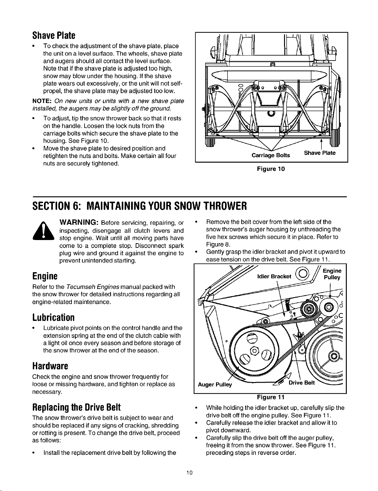
ShavePlate
• To check the adjustment of the shave plate, place
the unit on a level surface. The wheels, shave plate
and augers should all contact the level surface.
Note that if the shave plate is adjusted too high,
snow may blow under the housing. If the shave
plate wears out excessively, or the unit will not self-
propel, the shave plate may be adjusted too low.
NOTE: On new units or units with a new shave plate
installed, the augers may be slightly off the ground.
• To adjust, tip the snow thrower back so that it rests
on the handle. Loosen the lock nuts from the
carriage bolts which secure the shave plate to the
housing. See Figure 10.
• Move the shave plate to desired position and
retighten the nuts and bolts. Make certain all four
nuts are securely tightened.
Carriage Bolts Shave Plate
Figure 10
SECTION6: MAINTAININGYOURSNOWTHROWER
WARNING: Before servicing, repairing, or
inspecting, disengage all clutch levers and
stop engine. Wait until all moving parts have
come to a complete stop. Disconnect spark
plug wire and ground it against the engine to
prevent unintended starting.
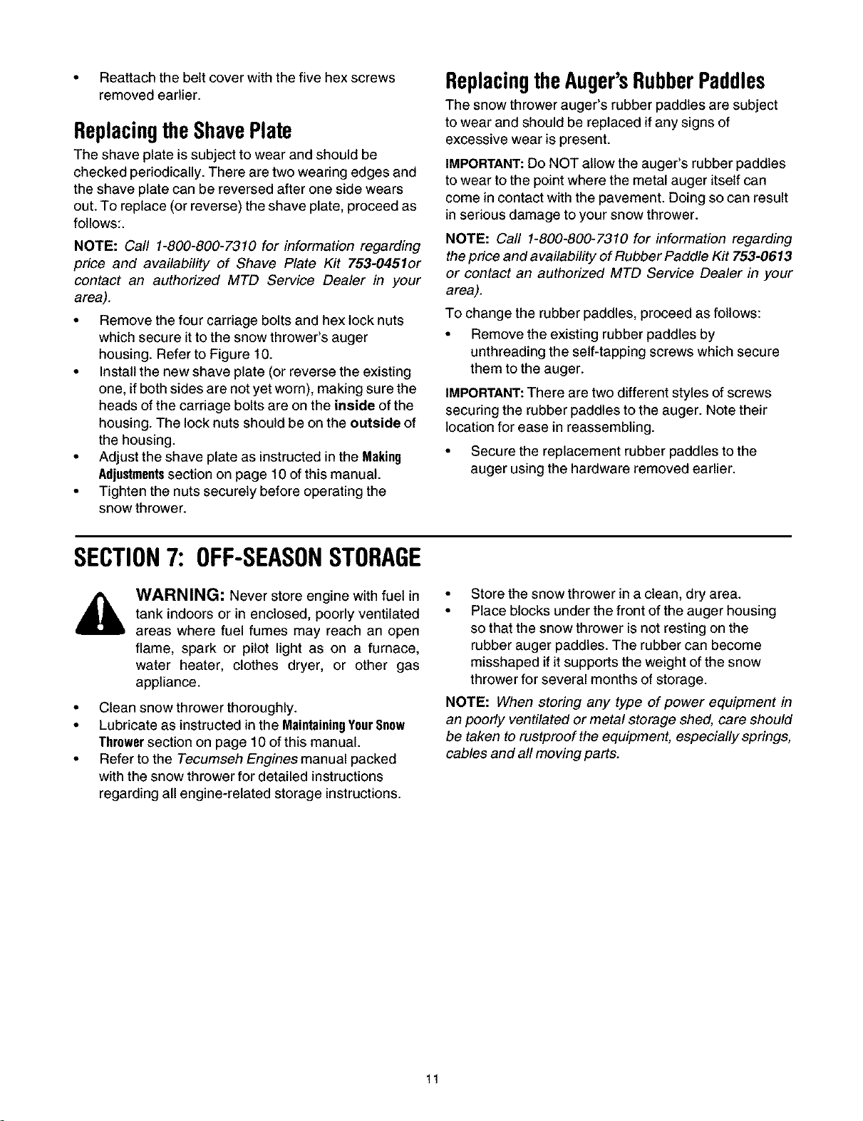
• Remove the belt cover from the left side of the
snow thrower's auger housing by unthreading the
five hex screws which secure it in place. Refer to
Figure 8.
• Gently grasp the idler bracket and pivot it upward to
ease tension on the drive belt. See Figure 11.
Engine
Refer to the Tecumseh Engines manual packed with
the snow thrower for detailed instructions regarding all
engine-related maintenance.
Lubrication
• Lubricate pivot points on the control handle and the
extension spring at the end of the clutch cable with
a light oil once every season and before storage of
the snow thrower at the end of the season.
Hardware
Check the engine and snow thrower frequently for
loose or missing hardware, and tighten or replace as
necessary.
Replacingthe DriveBelt
The snow thrower's drive belt is subject to wear and
should be replaced if any signs of cracking, shredding
or rotting is present. To change the drive belt, proceed
as follows:
• Install the replacement drive belt by following the
Auger Pulley
Pulley
Drive Belt
Figure 11
• While holding the idler bracket up, carefully slip the
drive belt off the engine pulley. See Figure 11.
• Carefully release the idler bracket and allow it to
pivot downward.
• Carefully slip the drive belt off the auger pulley,
freeing it from the snow thrower. See Figure 11.
preceding steps in reverse order.
10
• Reattachthebeltcoverwiththefivehexscrews
removedearlier.
ReplacingtheShavePlate
The shave plate is subject to wear and should be
checked periodically. There are two wearing edges and
the shave plate can be reversed after one side wears
out. To replace (or reverse) the shave plate, proceed as
follows:.
NOTE: Carl 1-800-800-7310 for information regarding
price and availability of Shave Plate Kit 753-0451or
contact an authorized MTD Service Dealer in your
area).
• Remove the four carriage bolts and hex lock nuts
which secure it to the snow thrower's auger
housing. Refer to Figure 10.
• Install the new shave plate (or reverse the existing
one, if both sides are not yet worn), making sure the
heads of the carriage bolts are on the inside of the
housing. The lock nuts should be on the outside of
the housing.
• Adjust the shave plate as instructed in the Making
Adjustmentssection on page 10 of this manual.
• Tighten the nuts securely before operating the
snow thrower.
ReplacingtheAuger'sRubberPaddles
The snow thrower auger's rubber paddles are subject
to wear and should be replaced if any signs of
excessive wear is present.
IMPORTANT: Do NOT allow the auger's rubber paddles
to wear to the point where the metal auger itself can
come in contact with the pavement. Doing so can result
in serious damage to your snow thrower.
NOTE: Call 1-800-800-7310 for information regarding
the price and availability of Rubber Paddle Kit 753-0613
or contact an authorized MTD Service Dealer in your
area).
To change the rubber paddles, proceed as follows:
• Remove the existing rubber paddles by
unthreading the self-tapping screws which secure
them to the auger.
IMPORTANT:There are two different styles of screws
securing the rubber paddles to the auger. Note their
location for ease in reassembling.
• Secure the replacement rubber paddles to the
auger using the hardware removed earlier.
SECTION7: OFF-SEASONSTORAGE
WARNING: Never store engine with fuel in
tank indoors or in enclosed, poorly ventilated
areas where fuel fumes may reach an open
flame, spark or pilot light as on a furnace,
water heater, clothes dryer, or other gas
appliance.
• Clean snow thrower thoroughly.
• Lubricate as instructed in the MaintainingYourSnow
Throwersection on page 10 of this manual.
• Refer to the Tecumseh Engines manual packed
with the snow thrower for detailed instructions
regarding all engine-related storage instructions.
• Store the snow thrower in a clean, dry area.
• Place blocks under the front of the auger housing
so that the snow thrower is not resting on the
rubber auger paddles. The rubber can become
misshaped if it supports the weight of the snow
thrower for several months of storage.
NOTE: When storing any type of power equipment in
an poorly ventilated or metal storage shed, care should
be taken to rustproof the equipment, especially springs,
cables and all moving parts.
11
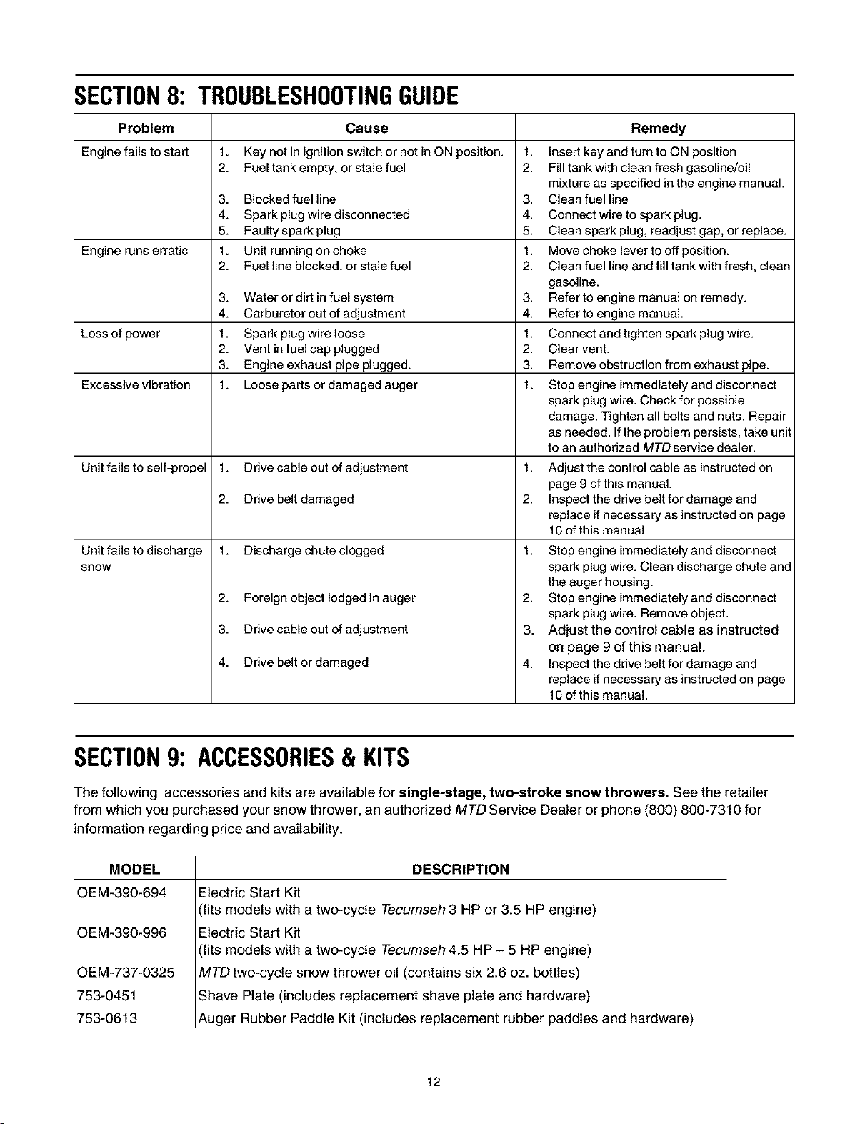
SECTION8: TROUBLESHOOTINGGUIDE
Problem Cause Remedy
Engine fails to start 1. Key not in ignition switch or not in ON position. 1. Insert key and turn to ON position
2. Fuel tank empty, or stale fuel 2. Fill tank with clean fresh gasoline/oil
mixture as specified in the engine manual.
3. Blocked fuel line 3. Clean fuel line
4. Spark plug wire disconnected 4. Connect wire to spark plug.
5. Faulty spark plug 5. Clean spark plug, readjust gap, or replace.
Engine runs erratic 1. Unit running on choke 1. Move choke lever to off position.
2. Fuel line blocked, or stale fuel 2. Clean fuel line and fill tank with fresh, clean
gasoline.
3. Water or dirt in fuel system 3. Refer to engine manual on remedy.
4. Carburetor out of adjustment 4. Refer to engine manual.
Loss of power 1. Spark plug wire loose 1. Connect and tighten spark plug wire.
2. Vent in fuel cap plugged 2. Clear vent.
3. Engine exhaust pipe plugged. 3. Remove obstruction from exhaust pipe.
Excessive vibration 1. Loose parts or damaged auger 1. Stop engine immediately and disconnect
spark plug wire. Check for possible
damage. Tighten all bolts and nuts. Repair
as needed. If the problem persists, take unit
to an authorized MTD service dealer.
Unit fails to self-propel 1. Drive cable out of adjustment 1. Adjust the control cable as instructed on
page 9 of this manual.
2. Drive belt damaged 2. Inspect the drive belt for damage and
replace if necessary as instructed on page
10 of this manual.
Unit fails to discharge 1. Discharge chute clogged 1.
snow
2. Foreign object lodged in auger
3. Drive cable out of adjustment
4. Drive belt or damaged
Stop engine immediately and disconnect
spark plug wire. Clean discharge chute and
the auger housing.
2. Stop engine immediately and disconnect
spark plug wire. Remove object.
3. Adjust the control cable as instructed
on page 9 of this manual.
4. Inspect the drive belt for damage and
replace if necessary as instructed on page
10 of this manual.
SECTION9: ACCESSORIES& KITS
The following accessories and kits are available for single-stage, two-stroke snow throwers. See the retailer
from which you purchased your snow thrower, an authorized MTD Service Dealer or phone (800) 800-7310 for
information regarding price and availability.
MODEL
OEM-390-694
OEM-390-996
OEM-737-0325
753-0451
753-0613
DESCRIPTION
Electric Start Kit
(fits models with a two-cycle Tecumseh 3 HP or 3.5 HP engine)
Electric Start Kit
(fits models with a two-cycle Tecumseh 4.5 HP - 5 HP engine)
MTD two-cycle snow thrower oil (contains six 2.6 oz. bottles)
Shave Plate (includes replacement shave plate and hardware)
Auger Rubber Paddle Kit (includes replacement rubber paddles and hardware)
12

NOTES
13
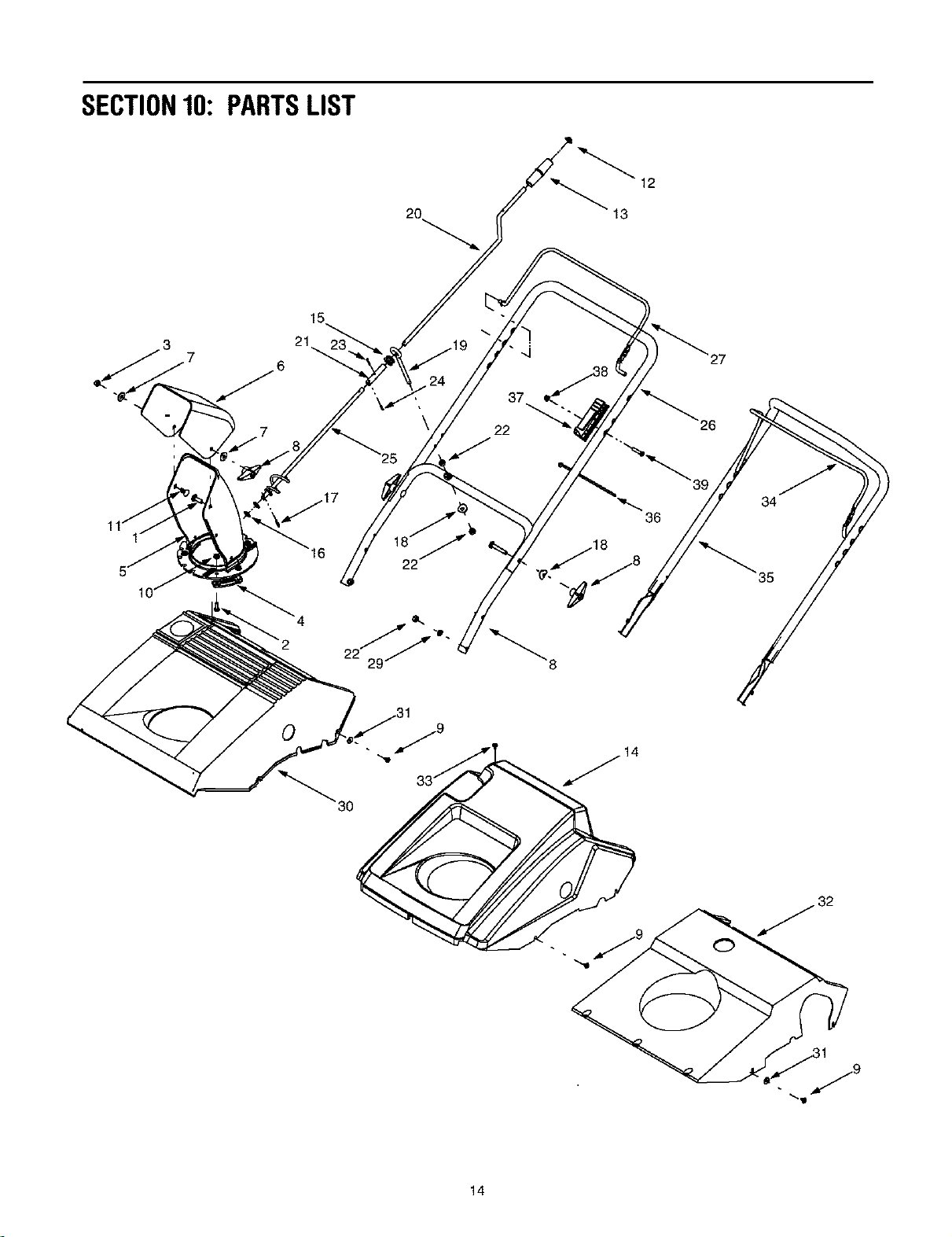
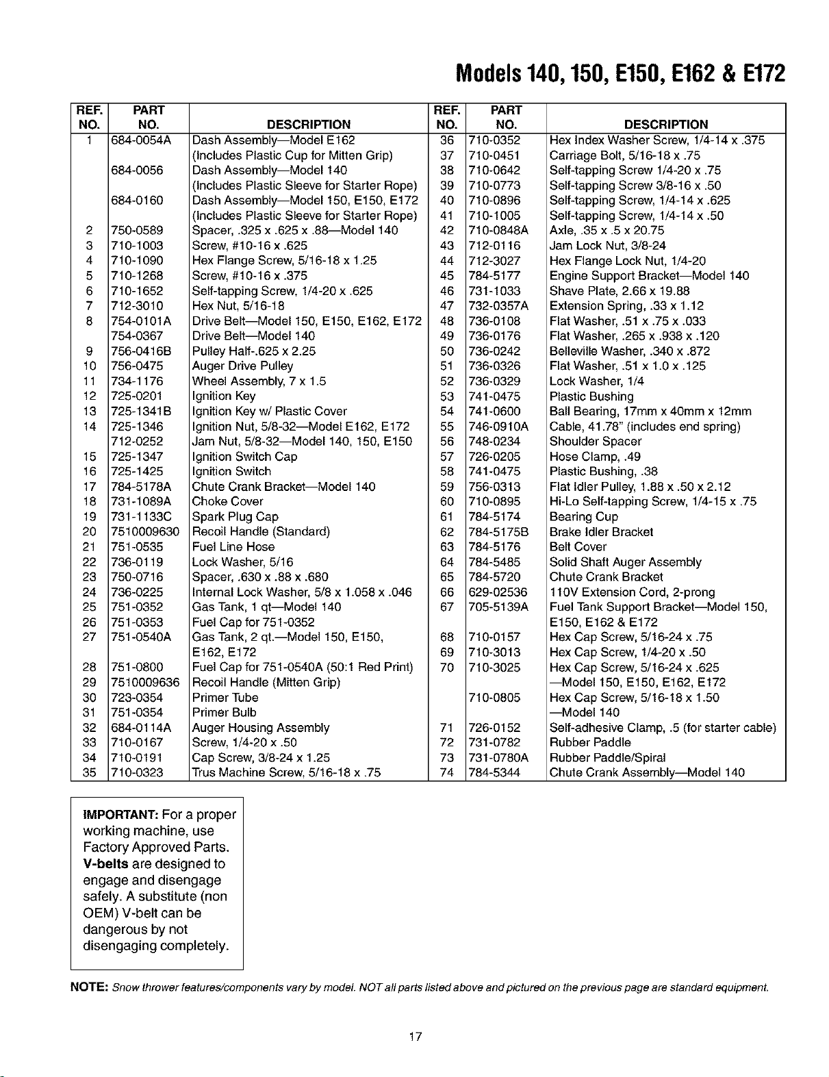
SECTION10: PARTSLIST
20
12
13
21
37
22
30
14
RER PART
NO. NO.
1 710-0276
2 710-3015
3 712-3068
4 731-0861A
6 731-0915B
6 731-0921
7 736-0159
8 720-0264
9 710-1266
10 712-3027
11 710-0461
12 726-0100
13 720-0201A
14 731-1766
15 735-0234
16 736-0186
17 714-0104
16 736-0451
19 747-0697
20 747-0737
21 750-0786
22 712-3010
23 714-0507
24 715-0136
25 684-0126
26 749-0706
27 747-0946
26 749-0796B
29 736-0119
30 731-1067
31 736-0400
32 731-0702
33 710-1003
34 747-0956
36 749-0711A
-- 720-0296
36 725-0157
37 746-0863
36 712-0324
39 710-1270
Models140,150,E150,E162& E172
DESCRIPTION
Splined Carriage Screw, 5/16-18 x 1.0
Hex Cap Screw, 1/4-20 x.75
Hex Lock Nut, 5/16-18
Chute Flange Keeper
Lower Chute, 5.0
Upper Chute, 5.0
Washer, .349 x .879 x .063
Wingnut Knob, 5/16-18
Screw, #10-16 x .375
Hex Flange Lock Nut, 1/4-20
Carriage Bolt, 5/16-18 x .75
Push Cap, 3/8
Knob, 1.0 x 3.2
Shroud, Black--Models E162 & E172
Rubber Grommet, .44 x .94 x .50
Flat Washer, .375 x .738 x .063
Internal Cotter Pin, .072 x 1.12
Saddle Washer, .320 x .93
Eyebolt, .70
Upper Chute Crank
Spacer, .382 x .50 x 1.12
Hex Nut, 5/16-18
Cotter Pin, 3/32 x .75
Roiled Pin, 1/8 x .63
Chute Crank Assembly
Upper Handle
Auger Bail (Control Handle)
Lower Handle
Lock Washer, 5/16
Shroud, Black--Models 150 & E150
Flat Washer, .194 x .62 x .063
Shroud, Black--Model 140
Screw, #10-16 x .625
Auger Bail (Control Handle), Gullwing-style
Upper Handle, Gullwing-style
Foam Grip, 22" (not included with handle)
Cable Tie
Control (Cable) Housing
Nylon Hex Lock Nut, 1/4-20
Machine Screw, 1/4-20 x 1.31
NOTE: Snow thrower features/comoonems vary ey model. NOT afl parts Itsted above and pictured on the prevtous page are standard equipmenL
15
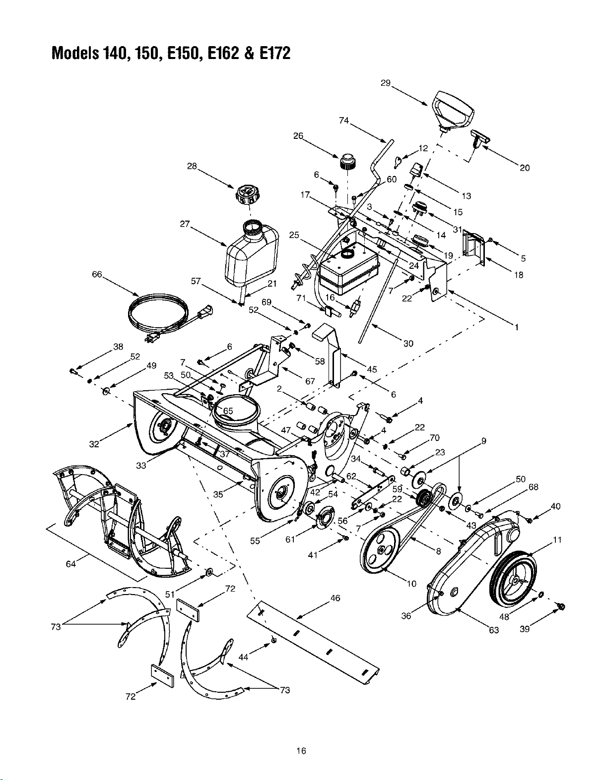
Models140,150,E150,E162& E172
74
2
20
17_ 13
25
67
<" 6 4
18
)
168
16
REF. PART
NO. NO.
1 684-0054A
684-0056
684-0160
2 750-0589
3 710-1003
4 710-1090
5 710-1268
6 710-1652
7 712-3010
8 754-0101A
754-0367
9 756-0416B
10 756-0475
11 734-1176
12 725-0201
13 725-1341B
14 725-1346
712-0252
15 725-1347
16 725-1425
17 784-5178A
18 731-1089A
19 731-1133C
20 7510009630
21 751-0535
22 736-0119
23 750-0716
24 736-0225
25 751-0352
26 751-0353
27 751-0540A
28 751-0800
29 7510009636
30 723-0354
31 751-0354
32 684-0114A
33 710-0167
34 710-0191
35 710-0323
Models140,150,E150,E162& E172
REF. PART
DESCRIPTION NO. NO.
Dash Assembly--Model E162 36 710-0352
(Includes Plastic Cup for Mitten Grip) 37 710-0451
Dash Assembly--Model 140 38 710-0642
(Includes Plastic Sleeve for Starter Rope) 39 710-0773
Dash Assembly--Model 150, E150, E172 40 710-0896
(Includes Plastic Sleeve for Starter Rope) 41 710-1005
Spacer, .325 x .625 x .88---Model 140 42 710-0848A
Screw, #10-16 x .625 43 712-0116
Hex Flange Screw, 5/16-18 x 1.25 44 712-3027
Screw, #10-16 x .375 45 784-5177
Self-tapping Screw, 1/4-20x.625 46 731-1033
Hex Nut, 5/16-18 47 732-0357A
Drive Belt--Model 150, E150, E162, E172 48 736-0108
DESCRIPTION
Hex Index Washer Screw, 1/4-14 x .375
Carriage Bolt, 5/16-18 x .75
Self-tapping Screw 1/4-20 x .75
Self-tapping Screw 3/8-16 x .50
Self-tapping Screw, 1/4-14 x .625
Self-tapping Screw, 1/4-14 x .50
Axle, .35 x .5 x 20.75
Jam Lock Nut, 3/8-24
Hex Flange Lock Nut, 1/4-20
Engine Support Bracket--Model 140
Shave Plate, 2.66 x 19.88
Extension Spring, .33 x 1.12
Flat Washer, .51 x .75 x .033
Drive Belt--Model 140 49 736-0176
Pulley Half-.625 x 2.25 50 736-0242
Auger Drive Pulley 51 736-0326
Wheel Assembly, 7 x 1.5 52 736-0329
Ignition Key 53 741-0475
Ignition Key w/Plastic Cover 54 741-0600
Ignition Nut, 5/8-32--Model E162, E172 55 746-0910A
Flat Washer, .265 x .938 x. 120
Belleville Washer, .340 x .872
Flat Washer, .51 x 1.0 x .125
Lock Washer, 1/4
Plastic Bushing
Ball Bearing, 17mm x 40mm x 12mm
Cable, 41.78" (includes end spring)
Jam Nut, 5/8-32--Model 140, 150, E150 56 748-0234
Ignition Switch Cap 57 726-0205
Ignition Switch 58 741-0475
Chute Crank Bracket--Model 140 59 756-0313
Choke Cover 60 710-0895
Spark Plug Cap 61 784-5174
Recoil Handle (Standard) 62 784-5175B
Fuel Line Hose 63 784-5176
Lock Washer, 5/16 64 784-5485
Spacer, .630 x .88 x .680 65 784-5720
Internal Lock Washer, 5/8 x 1.058 x .046 66 629-02536
Gas Tank, 1 qt--Mode1140 67 705-5139A
Fuel Cap for 751-0352
Gas Tank, 2 qt.--Mode1150, E150, 68 710-0157
E162, E172 69 710-3013
Fuel Cap for 751-0540A (50:1 Red Print) 70 710-3025
Recoil Handle (Mitten Grip)
Primer Tube 710-0805
Primer Bulb
Auger Housing Assembly 71 726-0152
Screw, 1/4-20 x .50 72 731-0782
Cap Screw, 3/8-24 x 1.25 73 731-0780A
Trus Machine Screw, 5/16-18 x .75 74 784-5344
Shoulder Spacer
Hose Clamp, .49
Plastic Bushing, .38
Flat Idler Pulley, 1.88 x .50 x 2.12
Hi-Lo Self-tapping Screw, 1/4-15 x .75
Bearing Cup
Brake Idler Bracket
Belt Cover
Solid Shaft Auger Assembly
Chute Crank Bracket
110V Extension Cord, 2-prong
Fuel Tank Support Bracket--Model 150,
E150, E162 & E172
Hex Cap Screw, 5/16-24 x .75
Hex Cap Screw, 1/4-20 x .50
Hex Cap Screw, 5/16-24 x .625
--Model 150, E150, E162, E172
Hex Cap Screw, 5/16-18 x 1.50
--Model 140
Self-adhesive Clamp, .5 (for starter cable)
Rubber Paddle
Rubber Paddle/Spiral
Chute Crank Assembly--Model 140
IMPORTANT: For a proper
working machine, use
Factory Approved Parts.
V-belts are designed to
engage and disengage
safely. A substitute (non
OEM) V-belt can be
dangerous by not
disengaging completely.
NOTE: Snow thrower features/components vary by model. NOT all parts listed above and pictured on the previous page are standard equipment.
17
INDICE
Contenido Pdgina
Medidas importantes de seguridad .......................................................................... 3
Montaje de la M_quina quitanieve ........................................................................... 5
Conozca las propiedades de la mAquina quitanieve ................................................ 7
Funcionamiento de la mAquina quitanieve ............................................................... 8
Realizaci6n de ajustes ............................................................................................. 9
Mantenimiento de la mAquina quitanieve ................................................................. 10
Almacenamiento fuera de temporada ...................................................................... 11
Gu[a para la soluci6n de problemas de la m_quina quitanieve ................................ 11
Lista de las piezas .................................................................................................... 12
BUSQUEDADELNUMERODEMODELO
Este manual de operaci6n es una parte importante de la nueva mAquina quitanieve. Le ayudara, a montar, preparar
y mantener la unidad para obtener los mejores resultados. Por favor lea y comprenda el contenido del manual.
Antes de comenzar el montaje de la mdquina quitanieve nueva, por favor encuentre la placa del
modelo del equipo y copie la informaci6n contenida en la misma en el espacio provisto a
continuaci6n. La informaci6n contenida en la placa det modeto es muy importante en caso de
necesitar ayuda de nuestro Departamento de Asistencia al Cliente o de un distribuidor autorizado.
Para encontrar el nQmero de modelo parese detras de la unidad en posici6n de operaci6n y mire hacia abajo
donde esta el panel de instrumentos. A continuaci6n se explica un ejemplo de placa de modelo. Para
referencias futuras, por favor copie el nQmero de modelo y el nQmero de serie del equipo en el espacio a
continuaci6n.
(N_mero de modeio) (N_mero de serie)
_,_ffc MTD PRODUCTS INC
LEVELAND, OHIO 441361
Copie el ndmero del modelo en este espacio:
Copie el ndmero de serie en este espacio:
SERVICIOTELEFONICODEASISTENCIAALCLIENTE
En caso de tener problemas para ensamblar este producto o de tener dudas con respecto a los controles,
funcionamiento o mantenimiento det mismo, por favor comun{quese con et Departamento de asistencia al cliente.
Llame al 1- (330) 220-4MTD (4683) o 1- (800)-800-7310 para comunicarse con un representante de
asistencia al cliente. Por favor cuando Ilame tenga a la vista el nQmero de modelo y el nQmero de
serie de su unidad. Consulte la secci6n anterior para obtener esta informaci6n. Se le solicitara que
ingrese et nQmero de serie para poder procesar su Ilamada.
18
SECCION1: MEDIDASIMPORTANTESDESEGURIDAD
ADVERTENCIA: La presencia de este simbolo indica que se trata de instrucciones importantes de seguridad
qua debe respetar pare evitar poner en riesgo su seguridad personal y / o material y de otras personas. Lea y siga
todas las instrucciones contenidas en este manual antes de intentar poner esta maquina en funcionamiento. De no
hacedo puede ocasionar lesiones. Cuando encuentre este simbolo --respete la advertencia que aparece a
continuacidn del mismo.
DVERTENCIA: El escape del motor de este producto, algunos de sus componentes y algunos componentes del
vehiculo contienen o emiten productos quimicos qua el estado de California considera qua pueden producir cancer,
defectos de nacimiento u otros problemas reproductivos.
PEMGRO: Estam_quinaest,,diseSadaparaserutilizadarespetandolasreglasdeseguridadcontenidaseneste
manual. AI igual qua con todos los equipos eldct rices si el operador es descuidado o comete errores puede ocasionar
]esiones graves. Esta m_,quina puede amputar manos y pies y arrojar objetos. De no respetar las instrucciones de
seguridad siguientes se pueden producir lesiones graves o la muerte.
Capacitaci6n
1. Lea, comprenda y respete todas las instrucciones qua figuran
en la m&quine o en este(es) manuel(es) antes de preceder al
monteje y operaciSn del equipo. Guarde este manual en un
lugar seguro pare referencias futures y regulares y para solicitar
repuestos.
2. Familiaricese con todos los contreles y con el uso adecuado de
los mismes. Sepa came detener la maquina y cdmo
desengranar los controles rApidamente.
3. Nunce permita qua nihos menores de 14 ahos operen esta
mAquina. Los niRos de 14 ahes y mAs deben leer y cemprender
las instrucciones de operaciSn y las reglas de seguridad
contenidas en este manuel y deben set capacitedos y
supervisados por uno de los padres.
4. Nunca permita que adultos sin conocimientoe acerce de la
mAquina operen la misma.
5. Los objetos errojados por le mAquina pueden producir lesienes
graves. Planifique el patron en el que va a ir errejando nieve
pera evitar que la descarga de material se realice hacia los
caminos, los observadores, etc.
6. Mantenga a los observadores, ayudantes, mascetas y a los
niSes por Io menos a 75 pies de la m_=quina mientras la misma
esta en funcionamiento. Detenga la m&quina si alguien entre en
la zone.
7. Sea precavido para evitar patinarse o caerse especialmente
cuendo opera la m&quina en reversa.
Preparatives
1. Revise minuciosamente la zona donde se utilizerA el equipo.
Saque todos los felpudos, dierios, trineos, tables, cables y otros
objetos extraSos con los qua podria tropezar o que podrian ser
arrojedos por la barrena / motor.
2. Pera protegerse los ojos utilice siempre anteojos o antiparras
de seguridad mientras opera la mAquina o mientras la ajusta o
repara. Los objetos arrojados qua rebotan pueden lesionar
gravemente la vista.
3. No opere la m&quina sin la vestimenta adecueda para estar al
aire libre en invierno. No utilice alhajas, bufandas largas u otras
prendas sueltas que podrian enredarse en las parfes mSviles.
Utilice un calzado antideslizante para las superficies
reebaladizas.
4. Use un cordSn prolongador y un tomecerriente de tres cables
con conexiSn e tierra para todas las unidades con motores con
encendido el_ctrico.
5. Ajuste la altura de la caja del tomacorriente pare limpiar la grave
o las superficies con piedras trituredas.
6. Desengrane todas las palancas de embrague antes de arrancer
el motor.
7. Nunca trate de realizer ning_n ejuste mientras el motor estA en
marcha, excepto cuando Io recomiende eepecfficamente el
manual de operacidn.
8. Deje que el motor y la mAquina se adapten ala temperatura
exterior antes de comenzar a secar la nieve.
9. Sea sumamente cuidadoso al manipular la gasoline para evitar
lesiones o dahos. La gasolina es altemente inflamable y los
vapores son explosivos. Se puede lesionar gravemente si
derrama gasoline sobre usted o sobre la rope ya que se puede
encender. Lave le piel y cAmbiese de rope de inmediato.
a. Utilice sSIo recipientes para gasolina aprebedos.
b. Apague todos los cigardllos, cigarros, pipas y otras
fuentes de cembustiSn.
c. Nunca cargue combustible en la mAquina en un espacio
cerrado.
d. Nunce saquela tepa del gas ni agregue combustible
mientras el motor est& caliente o en march&
e. Deje qua el motor se enfrie pot Io menos dos minutos
antes de volver a cargar combustible.
f. Nunca recargue el tanque de combustible. Uene el
tanque no mas de t/2 pulgada por debajo de la base del
cuello del filtro pare dejer espacio pare la dilataciSn del
combustible.
g. Vuelva a colocar la tape de la gasolina y ajL_stelabien.
h. Limpie la gasolina derramada sobre el motor y el
equipo. Traslade la mAquina a otra zone. Espere 5
minutos antes de encender el motor.
i. Nunca almacene la mAquina o el recipiente de
combustible en un espacio cerredo donde haya fuego,
chispas o luz piloto (por ejemplo, homos, calentadores
de ague, celefactores, secadores de ropa, etc.).
j. Deje qua la maquina se enfrie 5 minutos pot Io menos
antes de almacenada.
Funcionamiento
1. No ponga las manos e los pies cerca de las piezas rotatorias, en
la caja de le barrena / motor o en el canal de descerga. El
contacto con las plazas rotatodas puede producir la amputacion
de manos y pies.
2. La palanca del embrague de la barrena / motor es un dispositivo
de segurida& Nunca pase pot alto su funcionamiento. De
hacerlo la operaciSn de la mAquina es riesgosa y puede
ocasionar lesiones.
3. Las palancas del embrague deben funcionar bien en ambas
direcciones y regresar autematicamente ala posiciSn de
desengrane cuando se las suelta.
4. Nunca opere la mAquine si falta un canal de descarga o el
mismo est& dahado. Mantenga todos los dispositivos de
seguridad en su lugar yen funcionamiento.
19
5. Nunea eneienda el motor en espacioe cerrados o en una zona
poco ventilada. El escape del motor contiene mon6xido de
carbono, un gas inodoro y letal.
6. No opere la rn&quina estando bajo los efectos del alcohol o de
drogas.
7. El silenciador y el motor se calientan y producen una
quemadura. No los toque.
8. Sea sumamente precavido cuando opere la m&quina sobre una
superficie con grava o cuando la cruce. Mant6ngase alerta por
si se presentan peligros ocultos o trafico.
9. Tenga cuidado cuando cambie de direccl6n o cuando opere la
m&quina en pendientee.
10. Planifique el patr6n en el que va a ir arrojando nieve para evitar
que la descarga de material se produzca hacia las ventanas, las
paredes, los autos, etc. para evitar da_os materiales o lesiones
producidas por los rebotes.
11. Nunca dirija la descarga hacia los ni_os, los observadores ya
las mascotas ni deje que nadie se pare delante de la m&quina.
12. No eobrecargue la capacidad de la maquina tratando de sacar
la nieve muy r&pidamente.
13. Nunca opere esta maquina si no tiene buena visibilidad o
iluminaci6n. Siempre debe estar seguro de que esta bien
afirmado y sostenga bien las manijas. Camine, nunca corra.
14. Corte la corriente a la barrena / motor cuando transporte la
m&quina o cuando la misma no estA en uso.
15. Nunca opere la m&quina a alta velocidad de desplazamiento
sobre superficies resbaladizas. Mire hacia abajo y hacia atrAs y
tenga cuidado cuando la use en reversa.
16. Si la mAquina comenzara a vibrar de manera anormal, detenga
el motor, desconecte la bujia y p6ngala de manera que haga
masa contra el motor. Inspeccione la m&quina minuciosamente
para vet ei esta daSada. Repare todos los daSos antes de
encender y operar la maquina.
17. Desengrane todas las palancas de embrague y detenga el
motor antes de dejar la posici6n de operaci6n (detras de las
manijas). Espere a que la barrena / motor se detenga pot
completo antes de destapar el canal de descarga, de realizar
ajustes o inspecciones.
18. Nunca ponga las manos en las aberfuras de descarga o de
recolecci6n. Utilice siempre una herramienta de limpieza para
destapar la abertura de descarga.
19. Use s61o uniones y accesorios aprobados por el fabricante (por
ejemplo, pesas para las ruedas, cadenas para los neumAticos,
cabinas, etc.).
20. Si se presentan situaciones que no est&n previstas en este
manual sea cuidadoso y use el sentido com_n. Comuniquese
con su distribuidor o Ilame al tel6fono 1-800-800-7310 pot
ayuda y para obtener el hombre del distribuidor mas cercano.
Mantenimientoyalmacenamiento
1. Nunca manipule los dispositivos de seguridad de manera
imprudente. Controle periodicamente que funcionen de forma
adecuada.
2. Desengrane todas las palancas de embrague y detenga el
motor. Espere a que la barrena / motor se detenga pot
completo. Desconecte el cable de la bujia y p6ngalo de manera
que haga masa contra el motor para evitar que se encienda de
manera accidental antes de limpiar, reparar o revisar la
mAquina.
3. Controle frecuentemente que todos los pemos y tomillos est6n
bien ajustados para comprobar que la maquina se encuentra en
condiciones seguras de operacion. Ademas realice una
inspecci6n visual de la mAquina para controlar si la misrna estA
daSada.
4. No cambie la configuracion del regulador del motor ni acelere
demasiado el mismo. El regulador controla la velocidad m&xima
segura de operaci6n del motor.
5. Las placas de raspado y los zapatos anti deslizantes de que se
usan con la mAquina quitanieves se desgastan y se daSan. Para
su seguridad controle frecuentemente todos los componentes y
reemplAcelos solamente por repuestoe originales del fabricante
(O.E.M.). "iSi usa piezas que no cumplen con las
especificaciones del equipo original puede obtener resultados
ineorreetos y comprometer la seguridad!"
6. Revise los eontroles del embrague periodieamente para
verificar que engranen y desengranen adecuadamente y
aj_stelos si es necesario. Coneulte las instrucciones que figuran
en la secci6n sobre ajustes incluida en este manual de
operacion.
7. Mantenga o reemplaoe las etiquetas de eeguridad e
instrueeiones segQn sea neoeeario.
8. Respete las leyes y reglamentaciones referentes a la
disposici6n correcta de gas, aceite, etc. para proteger el medio
ambiente.
9. Antes de almacenar la mAquina enci_ndala unos minutoe para
sacar la nieve que haya quedado en la misma y para evitar asi
que se congele la barrena / motor.
10. Nunea almacene la mAquina o el reeipiente de combustible en
un espacio cerrado donde haya fuego, chispas o luz piloto como
pot ejemplo, calentadores de agua, homos, eecadores de ropa,
etc.
11. Consulte siempre el manual de operaci6n pot las instrueeiones
adeeuadas para el almacenamiento fuera de temporada.
Suresponsabilidad:
Solo permita que usen esta maquina electrica las personas que
lean, comprendan y respeten las advertenciae y las
instrueeiones que aparecen en este manual yen la m&quina.
I _vnt_w s'u°tvu]J° ev_ _'
,it_3wun_ l_t,_u _
Ho0H_vu_ _,_¢1_m_v_ vu_ _n
2O
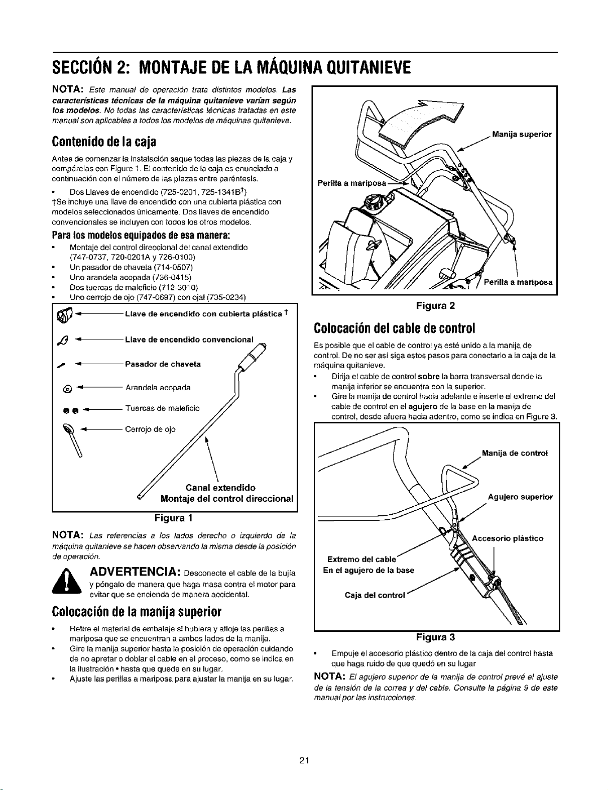
SECCION2: MONTAJEDELAMAQUINAQUITANIEVE
NOTA: Este manual de operaci6n trata distintos mode/as. Las
caracter[sticas t_cnicas de la m_quina quitanieve var[an segdn
los modelos. No todas las caracter/sticas tecnicas tratadas en este
manual son aplicables a todos los modelos de m#quinas quitanieve,
Contenidodelacaja
Antes de comenzar la instalaci6n saque todas las piezas de la caja y
comp&relas con Figure 1. El contenido de la caja es enunciado a
continuaciSn con el nQmero de las piezas entre parentesis.
Dos Llaves de encendido (725-0201,725-1341B t)
tSe incluye una Ilave de encendido con una cubierta plAstica con
modelos seleccionados Qnicamente. Dos Ilaves de encendido
convencionales se incluyen con todos los otros modelos.
Para los modelosequipadosdeesa manera:
Montaje del control direccional del canal extendido
(747-0737, 720-0201A y 726+0100)
Un pasador de chaveta (714-0507)
Uno arandela acopada (736-0415)
Dos tuercas de maleficio (712-3010)
Uno cerrojo de ojo (747-0697) con ojal (735-0234)
_< Llave de encendido con cubierta pl&stica t
Llave de encendido convencional
-9 Pasador de chaveta
_ Arandela acopada
@ O _ Tuercas de maleficio
,!_ Cerrojo de ojo
Canal extendido
Montaje del control direccional
Figura 1
NOTA: Las referencias a los lades derecho o izquierdo de la
maquina quitanieve se hacen observando la misma desde la posici6n
de operaci6n.
,_, ADVERTENCIA: Desconecte el cable de la bujia
y p6ngalo de manera que haga masa contra el motor para
evitar que se encienda de manera accidental,
Colocaci6ndelamanijasuperior
Retire el material de embalaje si hubiera y afloje las perillas a
mariposa que se encuentran a ambos lados de la manija.
Gire la manija superior hasta la posici6n de operaci6n cuidando
de no apretar o doblar el cable en el proceso, como se indica en
la ilustraci6n • hasta que quede en su lugar,
Ajuste las perillas a mariposa para ajustar la manija en su lugar.
Petilla a mariposa
Perilla a mariposa
Figura 2
Colocaci6ndelcabledecontrol
Es posible que el cable de control ya este unido a la manija de
control. De no ser asf siga estos pasos para conectarlo a la caja de la
m&quina quitanieve.
Dirija el cable de control sobre la barra transversal donde la
manija inferior se encuentra con la superior.
Gire la manija de control hacia adelante e inserte el extremo del
cable de control en el agujero de la base en la manija de
control, desde afuera hacia adentro, como se indica en Figure 3,
Manija de control
J
Agujeto superior
Extremo del cable
En el agujeto de la base
Caja del contro
Accesorio pl_stico
Figura 3
Empuje el accesorio plastico dentro de la caja del control hasta
que haga ruido de que qued6 en su lugar
NOTA: El agujero superior de la manija de control prev# el ajuate
de la tensi6n de la correa y del cable. Consulte la p&gina 9 de este
manual por las instrucciones.
21
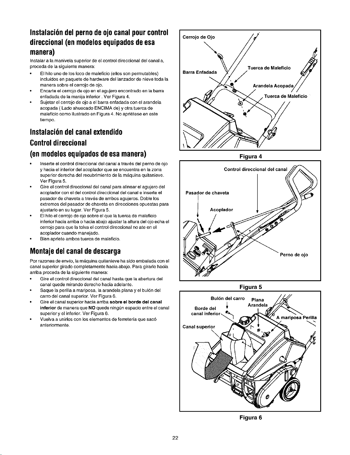
Instalaci6ndel pernodeojocanalpourcontrol
direccional(en modelos equipados de esa
manera)
[nstalar ale manivela superior de el control direccional del canal e,
proceda de la siguiente manera:
El hilo uno de los Ioco de maleficio (ellos son permutables)
incluidos en paquete de hardware del lanzedor de nieve toda la
manera sobre el cerrojo de ojo.
Encarte el cerrojo de ojo en el agujero encontredo en la barre
enfadada de la manila infedor. Ver Figure 4.
Sujetar el cerrojo de ojo a el barra enfadada con el arandela
acopada ( Lado ehuecado ENClMA de) y otra tuerca de
maleficio como ilust rado en Figura 4. No aprietese en este
tiempo.
Instalaci6ndelcanalextendido
Controldireccional
(enmodelosequipadosdeesamanera)
inserte el control direccional del canal a trav6s del perno de ojo
y hacia el interior del acoplador que se encuentra en la zona
superior derecha del recubnmiento de la mAquina quJtanJeve.
Ver Figura 5.
Gire el control direccional del canal pare alinear el agujere del
acoplador con el del control direccional del canal e inserte el
pasador de chaveta a traves de ambos agujeres. Doble los
extremos del pasador de chaveta en direcciones opuestas para
ajustarlo en su lugar. Vet Figura 5.
El hilo el cerrojo de ojo sobre el que latuerca de maleficio
inferior hacia arriba o hacia ebajo ajustar la altura del ojo echa el
cerrojo pare que la tolva el control direccional no ate en el
acoplador cuando manejado.
Bien apriete ambos tuerce de meleficio.
Montajedelcanaldedescarga
Por razones de envfo, la mAquina quitanieve ha side embalada con el
canal superior girado completamente hacie abajo. Pera girerlo hacie
arriba proceda de la siguiente manera:
Gire el control direccienal del canal haste que laabertura del
canal quede mirando derecho hacia adelante.
Saque la perilla a mariposa, la arandela plena y el bulSn del
carro del canal superior. Ver Figura 6.
Gire el canal superior hacia arriba sobre el borde del canal
inferior de manera que NO quede ningQn espacio entre el canal
superior y el inferior. Vet Figure 6.
Vuelva e unirlos con los elementos de ferreteda que sac6
anteriormente.
Cerrojo de Ojo
Tuerca de Maleficio
Barra Enfadada
\ ,/
Tuerca de Maleficio
Figura 4
Control direccional del cana i _
Pasedor de ehave_
Acoplador
_no de ojo
Figura 5
Bulbn del carro Plana
Botde del _ Arandela
canal inferior,
Canal superior
A mariposa Perilla
Figura 6
22
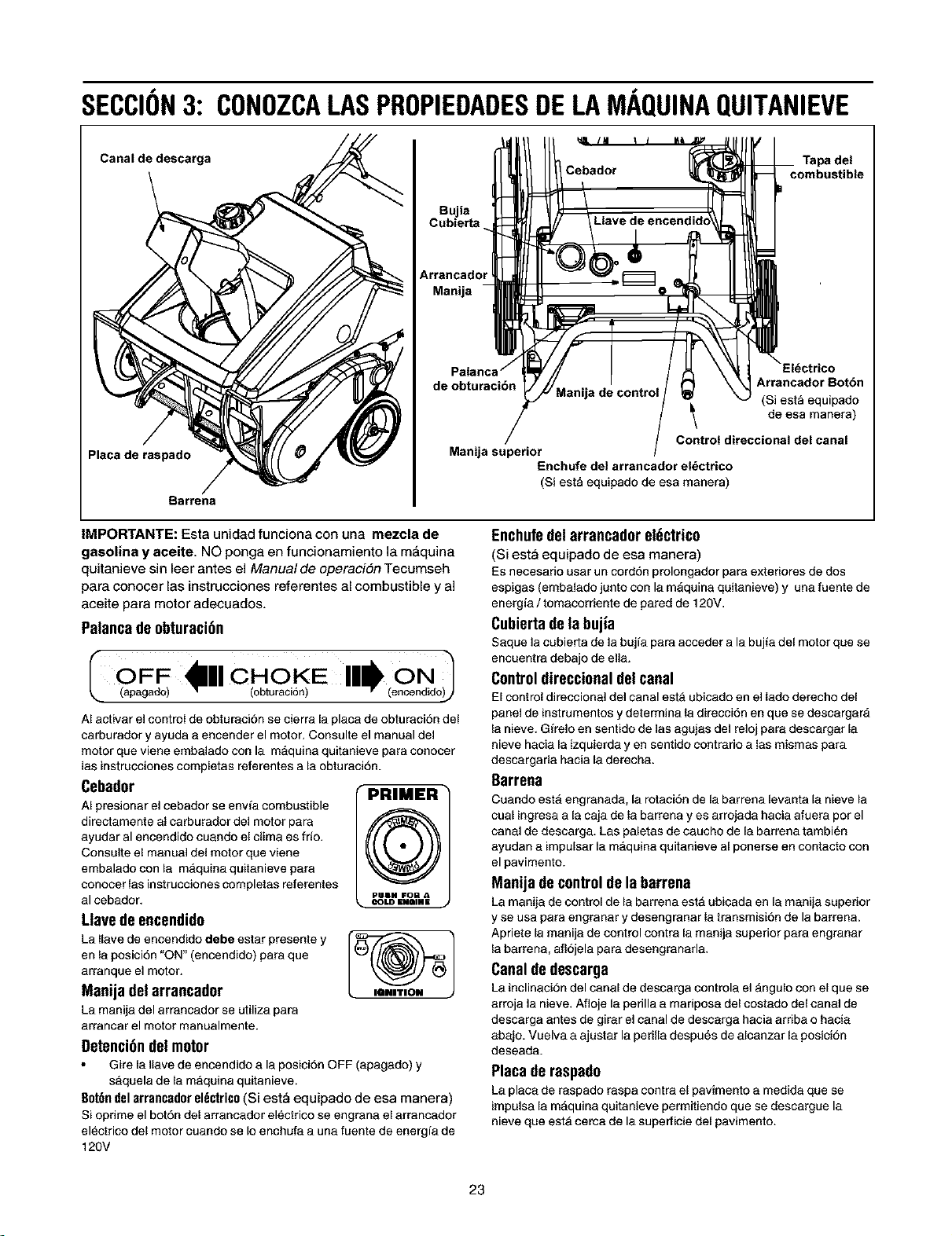
SECCION3: CONOZCALASPROPIEDADESDELAMAQUINAQUITANIEVE
Canaldedescarga
Placa de raspado
Barrena
Bujia
Cubierta
Arrsncadc
Manija
de obturaci6n
Tapa del
combustible
Arrancador Bot6n
(Si esta equipado
de esa manera)
Control direccional del canal
Manija superior
Enchufe del arrsncador el_ctrico
(Siesta equipado de esa manera)
IMPORTANTE: Esta unidad funciona con una mezcla de
gasolina y aceite. NO ponga en funcionamiento ta m_quina
quitanieve sin leer antes el Manual de operaci6n Tecumseh
para conocer las instrucciones referentes al combustible y a]
aceite para motor adecuados.
Palanca de obturaci6n
I £aFF 1_'1 CHOiKE "ll_i{£No)l
AI activar el control de obtur3cion se cierra la plac3 de obturaci6n deJ
carburador y ayuda 3 encender el motor. Consulte el manual del
motor que viene embalado con la mAquin3 quitanieve para conocer
las instrucciones completas referentes a la obturaci6n.
Cebador
AI presionar el cebador se env[a combustible
directamente al carburador del motor para f_
ayudar al encendido cuando el clima es frio,
Consulte el manual del motor que viene
embalado con la maquina quitanieve para
conocar las instrucciones completas referentes
PUIM FOR A
al cebador, =OLD=urn=
Llavede encendido
La Ilave de encendido debe estar presente y [_
en 13posici6n "ON" (encendido) para que
arranque el motor.
Manija delarrancador
La manija del arrancador se utiliza para
arrancar el motor manualmente.
getenci6ndel motor
Gire la 11avede encendido 3 la posici6n OFF (apagado) y
saquela de la maquina quitanieve.
aot6n del arrancador el_ctrico (Si est_ equipado de esa manera)
Si opfime el bot6n del arrancador el_ctrico se engran3 el 3rrancador
el_ctrico del motor cuando se Io enchufa a una fuente de energia de
120V
Enchufedel arrancadorel6ctrico
(Si est_ equipado de esa manera)
Es necesario usar un cord6n prolongador par3 exteriores de dos
espigas (embalado junto con la m&quina quitanieve) y una fuente de
energia / tomacorriente de pared de 120V.
Cubiertadelabujia
Saque la cubierta de la bujia par3 acceder a la buji3 del motor que se
encuentra debajo de ella,
Controldireccionaldelcanal
El control direccion31 del canal esta ubicado en el lado derecho del
panel de instrumentos ydetermina la direcci6n en que se descargar&
la nieve, G[re]o en sentido de las 3gujas del reloj par3 descargar la
nieve haci3 la izquierd3 yen sentido contrario alas mismas para
descargarla hacia la derecha.
Barrena
Cuando esta engranad3, la rotaci6n de la barrena levanta 13nieve la
cual ingrasa a la caja de 13barrena y es arrojad3 hacia afuera por el
canal de descarga. Las paletas de caucho de 13barrena t3mbi_n
ayudan 3 impulsar la m&quina quitanieve al ponerse en contacto con
el pavimento.
Manija decontroldela barrena
La manija de control de la barrena est& ubicada en la manij3 superior
y se usa para engranar y desengranar 13transmisi6n de la barrena.
Apriete la manija de control contra la manij3 superior para engranar
la barrena, aflojela par3 desengranarla.
Canaldedescarga
La inclinacion del canal de descarga controla el _ngulo con el que se
arroja la nieve, Afloje 13perilla 3 maripos3 del cost3do del canal de
descarga antes de gir3r el canal de descarg3 hacia arriba 0 haci3
ab3jo, Vuelva 3 ajustar la perilla despu6s de alcanzar la posicion
desead3.
Placaderaspado
La pl3c3 de r3spado r3spa contr3 el pavimento a medida que se
impulsa 13m&quin3 quitanieve permitiendo que se descargue la
nieve que est& cerca de la superficie del pavimento.
23
SECCION4: FUNCIONAMIENTODELAMAQUINAQUITANIEVE
ADVERTENCIA: Antes de encender el motor,
lea, comprenda y respete todas las instrucciones y
advertencias que figuran en la m&quina yen este manual
antes de operar el equipo.
Mezcladecombustibley aceite
ADVERTENCIA: Sea sumamente cuidadoso sl
manipular la gasolina. La gasoline es altamente
inflamable y los vapores son explosivos. Nunca cargue
combustible en la mAquina en un espacio cerrado o
cuando el motor est& caliente o en march& Apague todos
los cigarrillos, cigarros, pipes y otras fuentes de
combusti6n.
La m&quina quitanieve est& equipada con un motor de dos ciclos
que necesita una mezcla de gasoline y de aceite para motores de
dos ciclos en una proporci6n de 50:1. Consulte el manual de
operaci6n Tecumseh para motores pare conocer las instrucciones
completes en Io referente al aceite y la gasoline pare el motor de la
m&quina quitanieve.
Se coloca una cubeta plAstica en la abertura de carga del
tanque de combustible (debajo de la tapa del combustible) pare
evitar que ingresen escombros durante el montaje del producto.
Saque la cubeta y tfrela antes de Ilenar el tanque.
IMPORTANTE: NO opere la mAquina quitanieve sin antes ajustar
bien la taps del combustible en su lugar en el tanque de combustible.
Encendidodelmotor
Consulte elmanual de operaci6n Tecumseh pars motores
embalado con la mAquina quitsnieve para conocer las
instrucciones completes referentes al encendido del motor.
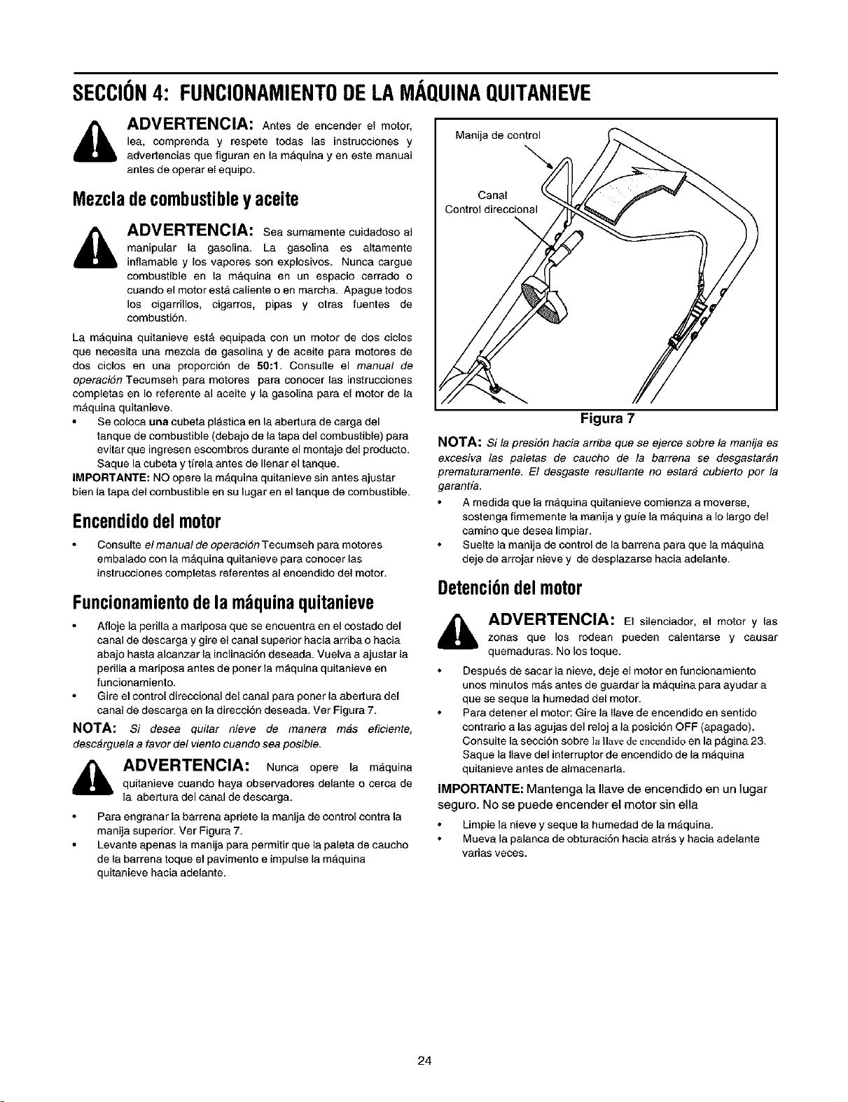
Funcionamientodelam quinaquitanieve
Atloje la perilla a mariposa que se encuentra en el costado del
canal de descarga y gire el canal superior hacia arriba o hacia
absjo hasta alcanzar la inclinaci6n deseada. Vuelva a ajustsr la
perilla a mariposa antes de poner la m&quina quitanieve en
tuncionamiento.
Gire el control direccional del canal pars poner la abertura del
canal de descarga en la direcci6n deseada. Ver Figura 7.
NOTA: Si desea quitar nieve de manera m#e efieiente,
desc_rguela a favor del viento cuando sea poeible.
dl_ ADVERTENCIA: aunca opere la m_quinaquitanieve cuando haya observadores delante o cerca de
la sbertura del canal de descarga.
Para engranar la bsrrena apriete la manija de control contra la
manija superior. Ver Figura 7.
Levante apenas la manija para permitir que la paleta de caucho
de la barrens toque el pavimento e impulse la m_quina
quitanieve hacia adelante.
Manija de control
Canal
Figura 7
NOTA: Si la presi6n hacia arriba que se ejerce sobre la manija es
excesiva las paletas de caucho de la barrena se desgastaran
prematuramente. El desgaste resultante no estar# cubierto por la
garantfa.
A medida que la maquina quitanieve comienza a moverse,
sostenga firmemente la msnija y gufe la m_quina a Io largo del
camino que desea Iimpiar.
Suelte la manija de control de Is barrena para que la maquina
deje de arrojsr nieve y de desplazarse hacia adelante.
Detenci6ndelmotor
i_ ADVERTENCIA: El silenciador, el motor y laszonas que los rodean pueden calentarse y causar
quemaduras. No los toque.
Despu6s de sacsr la nieve, deje el motor en funcionamiento
unos minutos mAs antes de guardar la m_=quinapara ayudar a
que se sequela humedad del motor.
Para detener el motor: Gire la Ilave de encendido en sentido
cont ratio alas agujas del reloj a la posici6n OFF (apagado).
Consulte la seccion sobre ]a Havedeencendido en la p_gina 23.
Saque la Ilave del interrupter de encendido de Is mAquina
quitanieve antes de almscenada.
IMPORTANTE: Mantenga la Ilave de encendido en un lugar
seguro. No se puede encender el motor sin ella
Limpie la nieve y sequela humedad de la m&quina.
Mueva la palanca de obturaci6n hacia atr_=sy hacia adelante
varias veces.
24
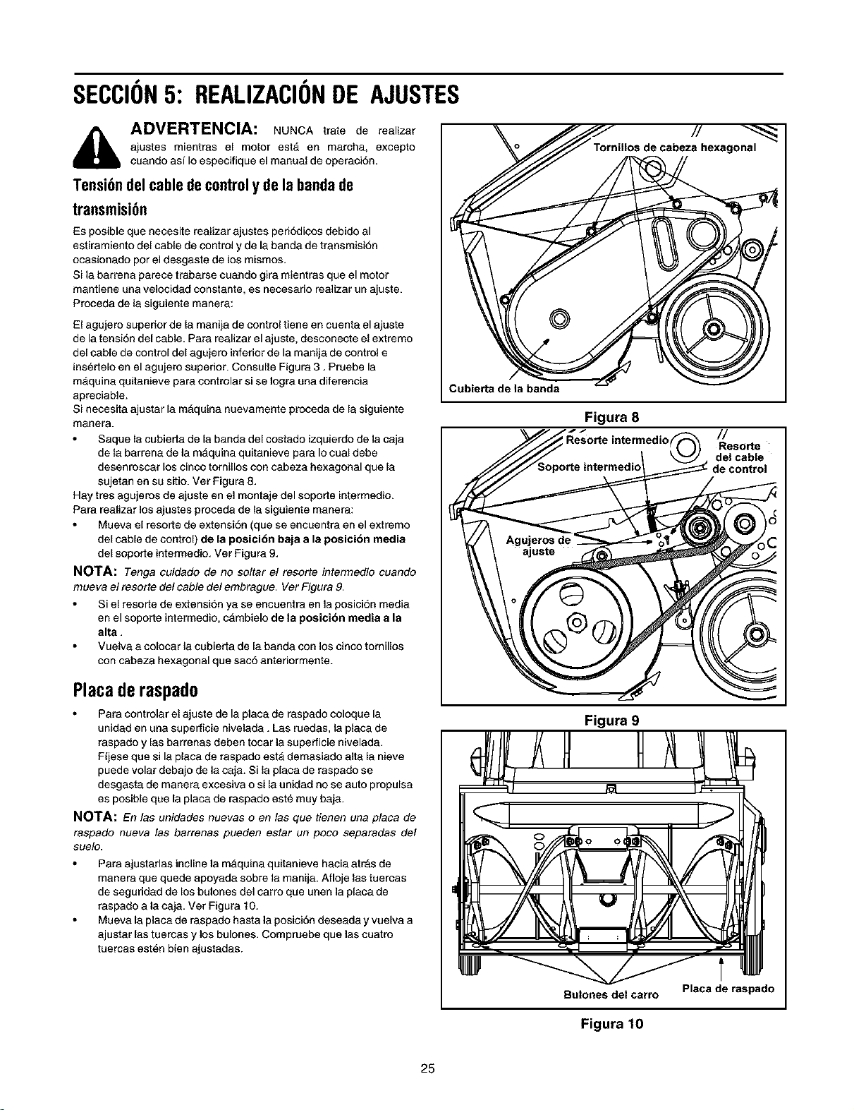
SECCION5: REALIZACIONDE AJUSTES
i_ ADVERTENCIA: NUNCA trate de realizar
ajustes mientras el motor est& en marcha, excepto
cuendo asf Io especifique el manual de operaci6n.
Tensi6ndelcabledecontroly de labandade
transmisi6n
Es posible que necesite realizar ajustes peri6dicos debido al
estiramiento del cable de control y de la banda de transmisi6n
ocasionado por el desgaste de los mismos.
Si la berrena parece traberse cuendo gira mientras que el motor
mantiene una velocidad constante, es neceserio realizar un ajuste.
Proceda de la siguiente manera:
El agujero superior de la manija de control tiene en cuenta el ajuste
de la tensi6n del cable. Pare realizar el ajuste, desconecte el extremo
del cable de control del agujero inferior de la manija de control e
insertelo en el egujero superior. Consulte Figura 3. Pruebe la
m&quina quitanieve pare controlar si se Iogra una diferencia
apreciable.
Si necesita ajuster le mAquina nuevamente proceda de la siguiente
manera.
Saquela cubierta de la banda del costedo izquierdo de la caja
de le berrena de la maquina quitanieve para Io cual debe
desenroscer los cinco tornillos con cabeze hexagonal que le
sujeten en su sitio. Vet Figura 8.
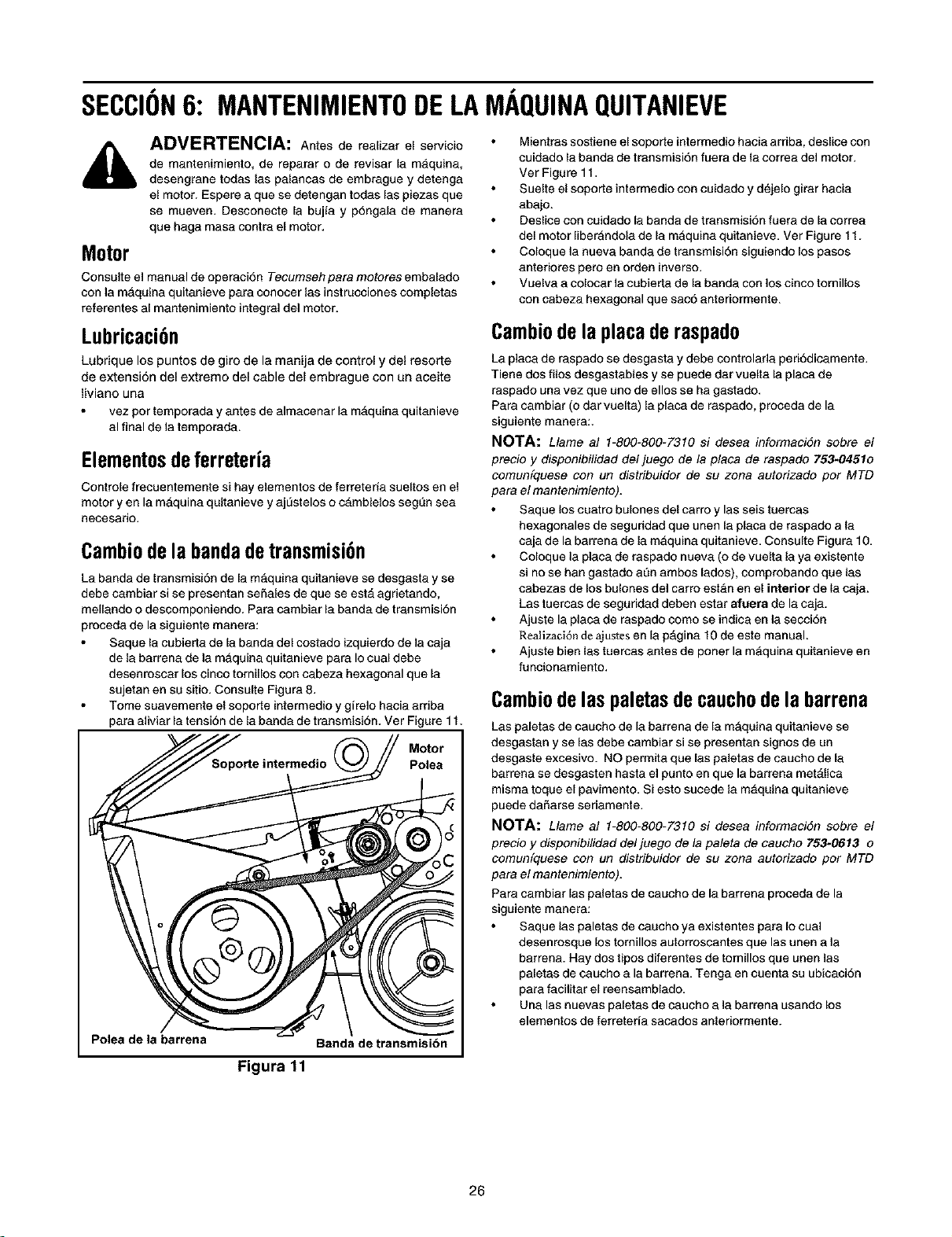
Hay tres agujeros de ajuste en el montaje del soporte intermedio.
Pera reafizar los ajustes proceda de la siguiente manera:
Mueva el resorte de extensi6n (que se encuentra en el extremo
del cable de control) de la posici6n baja a la posici6n media
del soporte intermedio. Ver Figure 9.
NOTA: Tongacuidado de no soltar el resorte intermedio cuando
mueva el resorte del cable del embrague, Ver Figura 9,
Si el resorte de extensi6n ya se encuentra en la posici6n media
en el soporte intermedio, cambielo de la posici6n media ala
alta.
Vuelva e colocar la cubierta de le bende con los cinco tomillos
con cabeza hexagonal que sac6 anteriormente.
Placaderaspado
Para controlar el ajuste de la place de respado coloque la
unidad en una supefficie nivelada. Las ruedas, laplaca de
raspado y las barrenes deben tocar la superficie nivelada.
Fijese que si laplaca de raspado est& demasiado elta le nieve
puede volar debajo de la caja. Si la placa de raspado se
desgasta de manere excesiva o si la unidad no se auto propulse
es posible que la place de raspado este muy beja.
NOTA: En las unidades nuevas o en las que tienen una place de
raspado nueva las barrenas pueden estar un poco separadas del
suelo.
Para ejustarlas incline la maquina quitanieve hacia atrAs de
manera que quede epoyada sobre la manije. Afloje las tuercas
de segurided de los bulones del carro que unen la place de
raspado ala ceja. Ver Figura 10.
Mueve le place de raspado hasta la posici6n deseada y vuelve a
ajuster los tuercas y los bulones. Compruebe que las cuatro
tuercas est6n bien ejustedas.
Cubierta de la banda
Figura 8
Figure 9
Bulones del catro
Figura 10
//
Resorte
del cable
de control
Placa de taspado
25
SECCION6: MANTENIMIENT0DELAMAQUINAQUITANIEVE
Motor
ADVERTENCIA: Antes de realizer el servicio
de mantenimiento, de reparar o de reviser la maquina,
desengrane todas las palancas de embregue y detenge
el motor. Espere a que se detengan todas las piezas que
se mueven. Desconecte la bujia y p6ngala de manere
que haga masa centre el motor.
Consulte el manual de opereei6n Tecumseh para motores embalado
con la maquina quitanieve para conocer las instrucciones completas
referentes al mantenimiento integral del motor.
Lubricaci6n
Lubrique los puntos de giro de la manija de control y del rosette
de extensidn del extreme del cable del embrague con un aceite
liviano una
vez per ternpereda y antes de alrnacenar la m&quina quitanieve
al final de la temporada.
Elementosdeferreteria
Controle frecuentemente si hay elementos de ferreteria sueltos en el
motor y en la m&quina quitanieve y ajL_steloso c&mbielos seg_n sea
necesado.
Cambiodelabandadetransmisi6n
La banda de transmisidn de la m_quina quitanieve se desgasta y se
debe cambiar si se presentan sefiales de que se est& agrietando,
mellando e descompeniendo. Pare cambiar la banda de trensmisi6n
precede de la siguiente manere:
Saquela cubierte de la banda del costede izquierdo de la ceja
de la barrena de la maquina quitanieve pare Io cual debe
desenroscar los cinco tornillos con cabeza hexagonal que la
sujetan en su sitio. Consulte Figure 8.
Tome suavemente el soporte intermedio y gfrelo hacia ardba
para aliviar la tensi6n de la banda de transmisi6m Vet Figure 11.
Motor
Polea
Polea de la barrena
Banda de transmisi6n
Figura 11
Mientres sostiene el soporte intermedio hacia arribe, deslice con
cuidedo la banda de transmisi6n fuere de la correa del motor.
Ver Figure 11.
Suelte el soporte intermedio con cuidado y d_jelo girar hacia
abejo.
Deslice con cuidado la banda de transmisi6n fuere de la correa
del motor liber&ndola de la mAquina quitanieve. Ver Figure 11.
Coloque la nueva banda de transmisi6n siguiendo los pasos
anteriores pete en orden inverse.
Vuelve a colocer la cubierta de la banda con los cinco tomillos
con cabeza hexagonal que sac6 anteriormente.
Cambiodela placaderaspado
Laplaca de respado se desgaste y debe controlada peri6dicamente.
Tiene dos files desgastables y se puede dar vuelta la place de
respado una vez que uno de ellos se ha gastado.
Para cambiar (o dar vuelta) laplaca de raspado, proceda de la
siguiente manera:.
NOTA: Llame al 1-800-800-7310 si desea informaciSn sobre el
precio y disponibilidad del juego de la placa de raspado 753-0451o
comunfquese con un distribuidor de su zona autorizado per MTD
para el mantenimiento).
Saque los cuatro bulones del carro y las seis tuercas
hexagonales de seguridad que unen laplaca de respado ala
caja de la barrena de la mAquina quitanieve. Consulte Figure 10.
Coloque laplaca de respado nueva (o de vuelta la ya existente
si no se han gastado aQn ambos lades), comprobando que las
cabezas de los bulones del carro estan en el interior de la ceja.
Las tuercas de seguridad deben estar afuere de la caja.
Ajuste la place de respado come se indica en la secci6n
Realizaci6n deajustes en la pAgina 10 de este manual.
Ajuste bien las tuercas antes de poner la mAquina quitanieve en
funcionamiento.
Cambiodelaspaletasdecauchodela barrena
Las paletas de caucho de la barrena de la maquina quitenieve se
desgastan y selas debe cembiar si se presentan signos de un
desgaste excesivo. NO permita que las paletas de caucho de la
barrena se desgasten hasta el punto en que la barrena metAlice
misma toque el pavimente. Si esto sucede la maquina quitanieve
puede daSarse seriamente.
NOTA: Llame al 1-800-800-7310 si desea informaciSn sobre el
precio y disponibilidad del juego de la paleta de caucho 753-0613 o
comunfquese con un distribuidor de su zona autorizado per MTD
para el mantenimiento).
Pare cambiar las paletas de caucho de la barrena proceda de la
siguiente menere:
Saque las paletas de caucho ya existentes para Io cual
desenrosque los tornillos autorroscantes que las unen e la
barren& Hay des tipos diferentes de tomillos que unen las
paletes de caucho ala barren& Tonga en cuenta su ubicacidn
para fecilitar el reensamblado.
Una las nuevas paletes de caucho ala barrena usando los
elementos de ferreterfa sacados anteriormente.
26
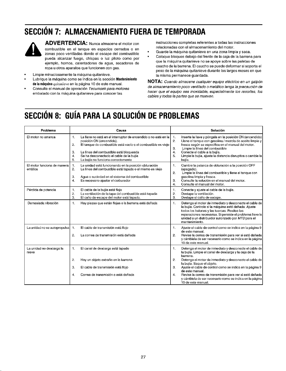
SECCION7: ALMACENAMIENTOFUERADETEMPORADA
ADVERTENCIA: Nunca almacene el meter con
combustible en el tanque en espacios cerrados o en
zonas peco ventiladas donde el escape del combustible
pueda alcanzar fuego, chispas o luz piloto come per
ejemple, hornos, calentadores de agua, secadores de
ropa u otros aparatos que funcionen con gas.
Limpie minuciosamente la maquina quitanieve.
Lubrique {a maquina come se indica en la secci6n Mantenimiento
dela m_quinaquitanieve en la p_gina 10 de este manual.
Consulte el manual de operaciSn Tecumseh para motores
embalado con la m&quina quitanieve para conocer las
instrucciones completas referentes a todas las instrucciones
relacionadas con el almacenamiento del motor.
Guarde [a mAquina quitanieve en una zona limpia y seca.
Coloque bloques debajo del frente de la caja de la barrena para
que la mAquina quitanieve no se apoye sobre laspaletas de
caucho de la barrena. El caucho se puede deformar si soporta el
peso de la maquina quitanieve durante los largos meses en que
la misma permanece guardada.
NOTA: Cuando almacene cualquier equipo electrico en un galp6n
de almacenamiento poco ventilado o rnet#lico tenga la precauci6n de
hacer que el equipo sea inoxidable, especialrnente los resortes, los
cables y todas la partes que se rnueven.
SECCION8: GUiAPARALASOLUCIONDEPROBLEMAS
Problema Causa Soluci6n
El motor no arranca 1. La Ilave no esta en el interrupter de encendido o no esta en la 1. Inserte la Ilave y p6ngala en la posici6n ON (encendido'j
posici6n ON (encendido). 2. Llene el tanque con gasolina / mezcla de aceite limpia y
2. El tanque de combustible estA vacfo o el combustible es viejo fresca segQn se especifica en el manual del motor.
3. Limpie la Ifnea del combustible
La rnea del combustible est& bloqueada 4. Conecte el cable a la bujfa.
Se ha desconectado el cable de la bujia 5. Limpie la bujia, ajuste la distancia disruprva o cambie la
La bujia no funciona correctamente buifa.
La unidad est& funcionando en la posici6n obturaci6n 1. Cambie la palanca de obturaci6n a la posici6n OFF
La rnea del combustible est& tapada o el mismo es viejo (apagado).
2. Limpie la Ifnea del combustible y Ilene el tanque con
Agua o suciedad en el sistema del combustible gasolina limpia y fresca.
Es necesario ajustar el carburador 3. Consulte la soluci6n en el manual del motor.
4. Consulte el manual del motor.
El cable de la bujla est& role 1. Conecte y ajuste el cable de la bujla.
La ventilaci6n de Ia tapa del combustible estA tapada 2. Dest ape la ventilaci6n.
El carlo de escape del motor estA tapado. 3. Destape el ca_o de escape.
Hay piezas que estAn flojas o la barrena estA da_ada 1. Detenga el motor de inmediato ydesconecte el cable de
la buiia. Controle si la m&quina est& da5ada. Ajuste
todos los bulones y Ias tuercas. Realice las
reparaciones necesarias. Si persiste el problema Ileve I_
unidad a un distribuidor autorizado per MTD para el
mantenimiento.
El cable de transmisi6n est& flojo 1. Aiuste el cable de control come se indica en la pAgina 9
de este maRuat.
La correa de transmisi6n estA darada 2. Revise la correa de transmisi6n para vet si est& daSada
y cAmbiela de ser necesario come se indica en la pAgin_
10 de este manual.
El canal de descarga estA tapado 1.
3.
4.
5.
El motor funciona de manera 1.
errAtica 2.
3.
4.
P6rdida de potencia 1.
2.
3.
Demasiada vibraci6n 1.
La unidad no se autopropulsa 1.
2.
La unidad no descarga la I.
nieve
2.
3.
4.
Hay un objeto extra5o en la barrena
El cable de transmisi6n est& flojo
Correa de transmisi6n o estA da_ada
2.
3.
4.
Detenga el motor de inmediato ydesconecte el cable de
la bujia. Limpie el canal de descarga y la caja de la
barrena.
Detenga el motor de inmediato ydesconecte el cable de
la bujia. Saque el obiet o.
Aiuste el cable de control come se indica en la pAgina 9
de este manuat.
Revise la correa de transmisi6n para vet si est& daSada
y cAmbiela de ser necesario come se indica en la pAgin_
10 de este manual.
27

NOTES
28

NOTAS
29

NOTAS
30
DEL FABRICANTE
GARANTIA LIMITADA
La garantfa limitada que se extiende a continuaci6n
es otorgada por la empresa MTD PRODUCTS INC
("MTD") con respecto a mercaderfas nuevas
compradas y utilizadas en los Estados Unidos, sus
posesiones y terdtorios.
MTD garantiza este producto por defectos matedales
y de fabricaci6n por un perfodo de dos (2) ahos a
part# de la fecha de la compra original y reparara, o
cambiar& sin cargo cuando Io considere pertinente
todas las piezas con defectos materiales o de
fabricaci6n. Esta garantfa limitada s61osera. aplicable
si et producto ha sido utilizado y mantenido segdn 1o
establecido en et Manual de operaci6n provisto junto
con el producto y no ha sufrido usos inadecuados,
abuso, usos comerciales, descuidos, accidentes,
mantenimiento incorrecto, alteraciones, vandalismo,
robo, incendio, agua producto de otros peligros o
desastres naturales. El dafio resultante por la
instalaci6n o et uso de accesorios o uniones no
aprobados por MTD Products Inc. para su uso con
el(los) producto(s) incluido(s) en este manual anulara
la garantfa en 1oque respecta a esos dafios.
Las piezas o componentes desgastables normales
esta.n sujetos a condiciones diferentes como se
indica acontinuaci6n: Todas las fallas de las piezas o
componentes desgastables normales estaran
cubiertas para et producto por un perfodo de 90 dfas
sin importar la causa. Despu_s de los 90 dfas, pero
dentro det perfodo de dos afios, las fallas de las
piezas desgastables normales ser&n cubiertas SOLO
SI fueron causadas por los defectos matedales o de
fAbrica de OTRAS piezas componentes. Las piezas
o componentes desgastables normales incluyen pero
no se limitan a correas, hojas, adaptadores para
hojas, bolsas para pasto, ruedas para la plataforma,
asientos, zapatos anti destizantes para la maquina de
sacar nieve, placas y gomas de corte. Las baterfas
esta.n cubiertas por una garantfa de reposici6n
limitada de 90 dfas.
OBTENCI(_N DEL SERVICIO DE
MANTENIMIENTO: El servicio de la garantfa esta
disponible, CON PRUEBA DE COMPRA A TRAVES
DEL DISTRIBUIDOR LOCAL AUTORIZADO PARA
EL MANTENIMIENTO. Para ubicar al distribuidor de
su zona, por favor controle si existe una lista en las
Paginas amaritlas o comunfquese con et
Departamento de asistencia al cliente de MTD
PRODUCTS INC Ilamando al 1-800-800-7310 o
escdbiendo al apartado postal P.O. Box 368022,
Cleveland, Ohio 44136-9722.
Esta garantfa limitada no Io cubrira en los siguientes
casos:El motor y las piezas componentes presentes.
Estos artfculos tienen una garantfa diferente a cargo
del fabricante. Por favor para estos artfculos consulte
la garantfa aplicable del fabricante.
Las bombas para el corte de madera, las valvulas y
los cilindros tienen una garantfa independiente de un
aho.
a.Los artfculos necesarios para el mantenimiento de
rutina como por ejemplo lubricantes, filtros, afiladores
de hojas, las adaptaciones y los ajustes como por
ejemplo los ajustes de los #enos, del embrague o de
la plataforma y el deterioro normal del acabado
exterior debido al uso o exposicion.
b. MTD no extiende ninguna garantfa para los productos
vendidos o exportados fuera de los Estados Unidos
de America, sus posesiones y territorios, excepto para
aquellos vendidos a trav6s de los canales autodzados
de distribuci6n de exportaciones de MTD.
No se aplican garantfas implfcitas, incluidas las
garantfas implicitas de comerciabilidad o de
adecuaci6n para un prop6sito determinado,
despuds del periodo de aplicaci6n de la garantfa
escrita expresa extendida mds arriba para las
piezas de acuerdo con su identificaci6n. Ninguna
otra garantfa expresa, oral o escrita, excepto la
mencionada anteriormente, extendida por
personas o personas juddicas, incluidos los
distribuidores o los minoristas con respecto a los
productos obligard a MTD. Durante el plazo de la
garantfa el dnico recurso es la reparaci6n o
reemplazo del producto como se indic6
anteriormente. (Algunos estados no permiten las
limitaciones a la duracibn de las garantfas implfcitas
por to que la limitaci6n antes mencionada puede no
serle de aplicaci6n.)
Las disposiciones incluidas en esta garantfa
proveen el recurso t_nico y exclusivo que surge
de las ventas. MTD no ser& responsable por
p_rdidas o daSos incidentales o directos,
incluyendo sin Ifmites los gastos incurridos para
los servicios de cuidado del pasto de reemplazo
o cambio, los gastos de transporte o los gastos
relacionados, o los gastos de alquiler para
reemplazar de manera transitoria un producto
bajo garantfa. (Algunos estados no permiten la
exclusi6n o limitaci6n de los dafios y perjuicios
incidentales o directos, por 1oque las limitaciones
mencionadas antedormente pueden no serle de
aplicaci6n.)
En ning0n caso se obtendr& una compensaci6n
mayor al monto det precio de compra det producto
vendido. La alteraci6n de las caracterfsticas de
seguridad del producto anularan esta garantfa. Usted
asume el riesgo y la responsabitidad por las perdidas,
dafios o lesiones que sufra Usted y sus bienes y / o
otras personas y sus bienes como consecuencia del
uso, del uso incorrecto o de la imposibilidad de uso de
este producto.
Esta garantfa limitada alcanza solamente al
comprador original, al arrendatario original o a la
persona que recibi6 et producto de regalo.
Relacibn de la ley estadual con esta garantia: Esta
garantfa limitada le otorga derechos legales
especfficos y puede tambien contar con otros
derechos que varfan de un estado a otro.
31
MANUFACTURER'S
LIMITED WARRANTY
The limited warranty set forth below is given by MTD
PRODUCTS INC ("MTD") with respect to new merchandise
purchased and used in the United States, its possessions
and territories.
MTD warrants this product against defects in material and
workmanship for a period of two (2) years commencing on
the date of original purchase and will, at its option, repair or
replace, free of charge, any part found to be defective in
material or workmanship. This limited warranty shall only
apply if this product has been operated and maintained in
accordance with the Operator's Manual furnished with the
product, and has not been subject to misuse, abuse, com-
mercial use, neglect, accident, improper maintenance,
alteration, vandalism, theft, fire, water or damage because
of other peril or natural disaster. Damage resulting from the
installation or use of any accessory or attachment not
approved by MTD Products Inc. for use with the product(s)
covered by this manual will void your warranty as to any
resulting damages.
Normal wear parts or components thereof are subject to
separate terms as follows: All normal wear part or compo-
nent failures will be covered on the product for a period of
90 days regardless of cause. After 90 days, but within the
two year period, normal wear part failures will be covered
ONLY IF caused by defects in material or workmanship of
OTHER component parts. Normal wear parts and compo-
nents include, but are not limited to, belts, blades, blade
adapters, grass bags, rider deck wheels, seats, snow
thrower skid shoes, shave plates and tires. Batteries are
covered by a 90-day limited replacement warranty.
HOW TO OBTAIN SERVICE: Warranty service is available,
WITH PROOF OF PURCHASE THROUGH YOUR LOCAL
AUTHORIZED SERVICE DEALER. To locate the dealer in
your area, please check for a listing in the Yellow Pages or
contact the Customer Service Department of MTD PROD-
UCTS INC by calling 1-800-800-7310 or writing to P.O. Box
368022, Cleveland, Ohio 44136-9722.
This limited warranty does not provide coverage in the
following cases:
a. The engine or component parts thereof. These items
carry a separate manufacturer's warranty. Please refer
to the applicable manufacturer's warranty on these
items.
b. Log splitter pumps, valves and cylinders have a sepa-
rate one year warranty.
c. Routine maintenance items such as lubricants, filters,
blade sharpening and tune-ups, or adjustments such
as brake adjustments, clutch adjustments or deck
adjustments; and normal deterioration of the exterior
finish due to use or exposure.
d. MTD does not extend any warranty for products sold
or exported outside of the United States of America,
its possessions and territories, except those sold
through MTD's authorized channels of export distribu-
tion.
NO implied warranty, including any implied warranty of
merchantability or fitness for a particular purpose,
applies after the applicable period of express written
warranty above as to the parts as identified. No other
express warranty or guaranty, whether written or oral,
except as mentioned above, given by any person or
entity, including a dealer or retailer, with respect to any
product shall bind MTD. During the period of the War-
ranty, the exclusive remedy is repair or replacement of
the product as set forth above. (Some states do not
allow limitations on how long an implied warranty lasts, so
the above limitation may not apply to you.)
The provisions as set forth in this Warranty provide the
sole and exclusive remedy arising from the sales. MTD
shall not be liable for incidental or consequential loss
or damages including, without limitation, expenses
incurred for substitute or replacement lawn care ser-
vices, for transportation or for related expenses, or for
rental expenses to temporarily replace a warranted
product. (Some states do not allow the exclusion or limita-
tion of incidental or consequential damages, so the above
exclusion or limitation may not apply to you.)
In no event shall recovery of any kind be greater than the
amount of the purchase price of the product sold. Alteration
of the safety features of the product shall void this War-
ranty. You assume the risk and liability for loss, damage, or
injury to you and your property and/or to others and their
property arising out of the use or misuse or inability to use
the product.
This limited warranty shall not extend to anyone other than
the original purchaser, original lessee or the person for
whom it was purchased as a gift.
How State Law Relates to this Warranty: This limited
warranty gives you specific legal rights, and you may also
have other rights which vary from state to state.