Loading ...
Loading ...
Loading ...
18 31-5000564 Rev. 3
ENGLISH
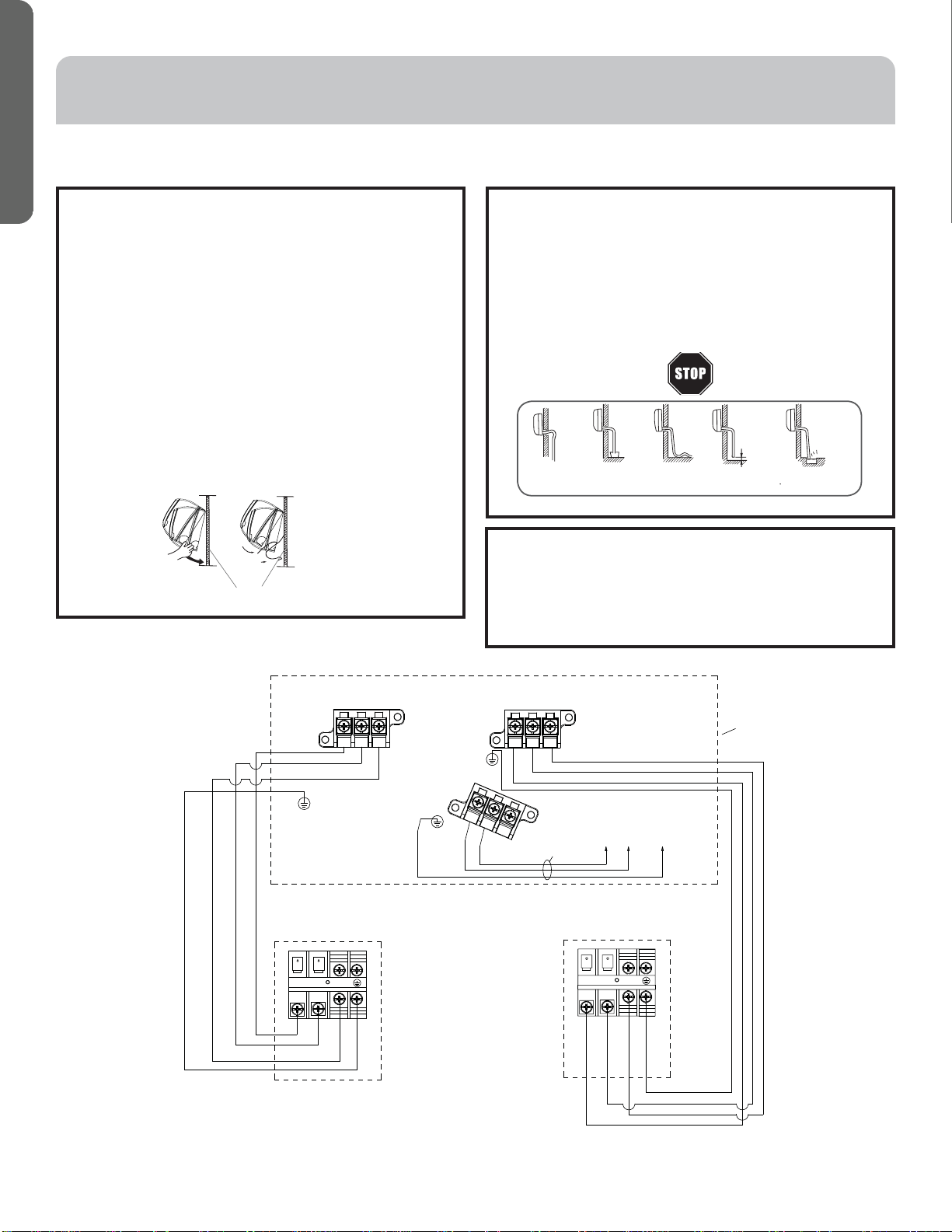
Note: Above diagram only demonstrates the wiring connection between outdoor & indoor for dual zone as an example.
123123
1
L
2
L
ABtinU roodtuO
AC 208/230 Volt Supply
L1 to L1, L2 to L2, ground to ground
)C(3 )L(2 )N(1
A tinU roodnI
)C(3 )L(2 )N(1
B tinU roodnI
elbac ylppus rewoP
INSTALLATION INSTRUCTIONS
E. Mount Indoor Unit to Mounting Plate
• Bundle the refrigerant piping, drain piping, and wiring
with tape and carefully route the bundle through the
piping hole.
• With the top of the indoor unit closer to the wall, hang
the indoor unit on the upper hooks of the mounting
plate. Slide the unit slightly side to side to verify proper
placement.
• Rotate the lower portion of the indoor unit to the
mounting plate, pushing the unit up slightly, rotate the
lower part of the unit fully against the wall, then pull
down do the lower hooks engage the brackets. (see
illustration)
• Verify the unit is secured and flush to the wall.
• Indoor Unit installation is finished at this time.
F. Condensate Drainage Pipe
• Verify the condensate drain line has a constant pitch
downward for proper water flow. There should be no
kinks or rises in the tubing which may cause a trapping
effect of the water (see illustration).
Optional: Can use PVC pipe by connecting a 1” ID PVC
pipe to the drain line coming out of the wall and running
to desired location.
mounting plate
Step 2 - Installation of the Indoor Unit (Cont.)
G. To Remove the Indoor Unit
• Slightly raise the entire unit.
• Pull the lower portion of the unit off the lower hooks and
pull slightly away from the wall.
• Lift the upper portion of the unit off the upper hooks.
It becomes
high midway. The gap with the
ground is too small There is the bad
smell from a sewer
It waves.
The end is imm-
ersed in water.
Less than
5cm
Loading ...
Loading ...
Loading ...