Gas Range Top and Range
User Manual
and
Installation Instructions
IMPORTANT SAFETY INSTRUCTIONS
Carefully read the important information
regarding installation, safety and maintenance.
Keep these instructions for future reference.
MAAN2160-07
2022-01-26
Chef Induction Cooktop
30” and 36”
User Manual
&
Installation Instructions
IMPORTANT SAFETY INSTRUCTIONS
Carefully read the important information
regarding installation, safety and maintenance.
Keep these instructions for future reference.
MAAN2402-EN-2
2021-07-05
AN-2160 / AN-2161 / AN-2162
AN-2230SS / AN-2236SS / AN-2248SS / AN-2230WHT / AN-2236WHT
/ AN-2248WHT / AN-2230SSBK / AN-2236SSBK / AN-2248SSBK
— 2 —
INSTALLERS - Start Here
Safety Instructions are on pages 4 to 10 and
Installation Instructions are on pages 11 to 22.
Please perform these steps:
1. Read the safety instructions.
2. Read all instructions in the Installation section of this
manual BEFORE installing the appliance.
3. Remove all packing materials from the oven before
connecting the gas supply.
4. Observe all governing codes and ordinances.
5. When nished, make sure to leave these instructions with the consumer.
6. Installation is only to be done by a qualied technician, but ultimately proper
installation is the responsibility of the installer.
7. Product failure due to improper installation is not covered under the Warranty.
CONSUMERS - Start Here
Safety Instructions are on pages 23 to 24 and
Operating Instructions are on pages 25 to 33.
Please perform these steps:
1. Read the safety instructions.
2. Read all instructions in the manual BEFORE
operating the appliance.
3. Remove all packing materials from the oven before using.
4. Observe all governing codes and ordinances.
5. Installation is only to be done by a qualied technician, but ultimately proper
installation is the responsibility of the installer.
6. Product failure due to improper installation is not covered under the Warranty.
Before You Begin

— 3 —
Before You Begin ..................................................................................................................................... 2
Table of Contents .................................................................................................................................... 3
Important Safety Information .................................................................................................................. 4
Installation ............................................................................................................................................. 11
Included Parts ................................................................................................................................. 11
Tools and Additional Parts Needed ................................................................................................. 12
Range Top Dimensions ................................................................................................................... 13
Range Dimensions .......................................................................................................................... 14
Gas Range Top Specications ........................................................................................................ 15
Gas Range Specications ............................................................................................................... 15
Step 1 - Read the Safety Precautions ............................................................................................. 16
Step 2 - Plan Desired Location, Unpack the Range and Prepare Tools ......................................... 16
Step 3A (range tops only) - Prepare Cut-Out .................................................................................. 16
Step 3B (ranges only) - Dimensions and Clearances ..................................................................... 17
Step 4 - Gas Connection ................................................................................................................ 17
Step 5 - Liqueed Petroleum (Propane) Gas Conversion ............................................................... 19
Adjusting the Regulator Pressure ...................................................................................... 19
Changing Burner Nozzles .................................................................................................. 20
Step 6 (ranges only) - Install Anti-Tip Bracket ................................................................................ 21
Step 7 - Connect to AC................................................................................................................... 21
Step 8 - Finish Installation............................................................................................................... 22
Safety Before Operating ........................................................................................................................ 23
Operation ............................................................................................................................................... 25
Guidelines for Using Cooktop Burners ........................................................................................... 25
Surface Burner Ignition ................................................................................................................... 25
Heat Settings .................................................................................................................................. 25
Simmer and Boil .............................................................................................................................. 26
Flame Size ....................................................................................................................................... 26
Power Failure .................................................................................................................................. 26
Cooktop .......................................................................................................................................... 26
Burner Grates .................................................................................................................................. 26
Oven Vent (ranges only) .................................................................................................................. 27
Oven Operation (ranges only) ......................................................................................................... 27
Broiler Operation (ranges only) ....................................................................................................... 28
Griddle Operation (applicable models only) .................................................................................... 29
Maintenance .......................................................................................................................................... 29
Replacing the Oven Light (ranges only) .......................................................................................... 29
Removing the Oven Door and Kick Plate (ranges only) .................................................................. 30
Care and Cleaning ................................................................................................................................. 31
Troubleshooting Tips ............................................................................................................................. 33
Table of Contents
— 4 —
Important Safety Information
READ ALL INSTRUCTIONS BEFORE USE
Read and follow all instructions before using your oven to prevent the risk of re, electric shock, personal
injury, or damage when using the appliance. This guide does not cover all possible conditions that may occur.
Always contact your service technician or manufacturer about problems that you do not understand.
DANGER: When you see this symbol in the instructions, it indicates a hazardous
situation which, if not avoided, could result in death or serious injury.
WARNING: When you see this symbol in the instructions, it indicates a hazardous
situation which, if not avoided, could result in minor or moderate injury.
WHAT TO DO IF YOU SMELL GAS
• Openallwindowsstartingwiththoseclosesttotheappliance.
• DONOTtrytolightanyappliance.
• DONOTtouchanyelectricalswitchoroutlet.
• DONOTuseanyphoneinyourhome/building.
• Immediatelycallyourgassupplierfromaneighbor’sphone.Followthegassupplier’sinstructions.
• Ifyoucannotreachyourgassupplier,calltheredepartment.
INSTALLATION
• Removealltapeandpackagingbeforeusingtheappliance.Neverallowchildrentoplaywithpackagingmaterial.
• Dispose the carton and plastic bags after the appliance is unpacked. Cartons covered with rugs, bedspreads, or plastic
sheets can become air-tight chambers.
• Remove all staples from the carton. Staples can cause severe cuts and destroy nishes if they come in contact with
other appliances or furniture.
• Donotremovethemodel/serialplateattachedtotheappliance.
• BesureyourapplianceisproperlyinstalledandgroundedbyaQUALIFIEDTECHNICIANinaccordancewithalllocal
codes and ordinances and with the National Fuel Gas Code ANSI Z223.1—latest edition and the National Electrical
Code ANSI/NFPA No. 70—latest edition in United States, or CAN/CGA B149.1, B149.2, and the Canadian Electrical
Code, Part 1, in Canada.

— 5 —
Important Safety Information
WARNINGS
• Donotstoreorusegasoline,liquidpropanecylinderor
other ammable vapors and liquids in the vicinity of this
or any other appliance.
• Gasleakscannotalwaysbedetectedbysmell.
• Gassuppliersrecommendthatyouuseagasdetector
approved by UL or CSA. For more information, contact
your gas supplier.
• Ifagasleakisdetected,followthe“Whattodoifyou
smell gas” instructions on the previous page.
• Installationandservicemustbeperformedbyaqualied
installer, servicer or the gas supplier. Ask your dealer
to recommend a qualied technician and an authorized
repair service. Know how to shut off gas supply at
the meter and disconnect the electrical power to the
appliance at the circuit breaker or fuse box in case of an
emergency. Have the installer show you the location of
the appliance gas shut-off valve and how to shut it off
if necessary.
• Donotrepairorreplaceanypartoftheapplianceunless
specically recommended in this manual. All other
servicing should be done only by a qualied technician.
This may reduce the risk of personal injury and damage
to the appliance.
• Proper Installation: The appliance, when installed,
must be electrically grounded in accordance with
local codes or, in the absence of local codes, with the
National Electrical Code, ANSI/NFPA 70. In Canada, the
appliance must be electrically grounded in accordance
with Canadian Electrical Code. Be sure the appliance
is properly installed and grounded by a qualied
technician.
• Disconnectpowerbeforeservicing.
• Nevermodifyoraltertheconstructionoftheappliance
by removing panels, wire covers or any other part of
the product.
• Injuriesmayresultfromthemisuseofappliancedoors
such as stepping, leaning, or sitting on the doors.
• Overheadrangehoods,whichoperatebyblowinga
downward air ow on to the appliance, shall not be used
in conjunction with gas appliances other than when
the hood and appliance have been designed, tested
and listed by an independent test laboratory for use in
combination with each other.
• Ifapplianceislocatednearawindow,NEVERhanglong
curtains or paper blinds on that window. They could
blow over the surface burners and ignite, causing a
re hazard.
• Ensurethattheroomiswellventilatedbykeepingtheair
intakes open and in good working order or by installing
an extractor hood with discharge pipe. If the appliance
is used intensively for a long time the effectiveness of
the ventilation will have to be increased, for example
by opening a window or increasing the power of any
electric extractor fan.
• Flammablematerialsshouldnotbestoredonthe
appliance or near surface units. This includes paper,
plastic and cloth items, such as cookbooks, plastic
ware and towels, as well as ammable liquids. Do not
store explosives, such as aerosol cans, on or near the
appliance. Flammable materials may explode and result
in re or property damage.
• Maintenance: Keep appliance area clear and free from
combustible materials, gasoline, and other ammable
vapors and liquids.
• Storage in or on the appliance: Flammable materials
should not be stored in an oven or near surface units.
IN THE STATE OF MASSACHUSETTS, THE FOLLOWING
INSTALLATION INSTRUCTIONS APPLY:
• Installationsandrepairsmustbeperformedbya
qualied or licensed contractor, plumber, or gas-tter
qualied or licensed by the State of Massachusetts.
• Ifusingaballvalve,itshallbeaT-handletype.
• Aexiblegasconnector,whenused,mustnotexceed
three feet.
STATE OF CALIFORNIA PROPOSITION 65 WARNINGS:
• TheCaliforniaSafeDrinkingWaterandToxic
Enforcement Act requires the Governor of California to
publish a list of substances known to the state to cause
birth defects or other reproductive harm and requires
businesses to warn customers of potential exposure to
such substances.
• Gasappliancescancauseminorexposuretothree
of these substances, namely, carbon monoxide,
formaldehyde and soot, caused primarily by the
incomplete combustion of natural gas or LP fuels.
Properly adjusted burners, indicated by a bluish rather
than yellow ame, will minimize incomplete combustion.
Exposure to these substances can be minimized by
venting with an open window or by using a ventilation
fan or hood.
— 6 —
Important Safety Information
DANGER
• Donotstoreitemsofinteresttochildreninthecabinets
above the appliance or on the back splash of appliance.
Children should not be left alone or unattended in the
area where appliance is in use. Do not allow children to
climb or play around the appliance. They should never
be allowed to sit or stand on any part of the appliance.
Children climbing on the appliance to reach items could
be seriously injured.
• DONOTTOUCHTHECOOKINGSURFACE,THE
BURNERS, GRATES, OR ANY AREAS NEAR THEM.
Surface burners or appliance may be hot even though
ames are not visible. Areas near surface burners or
appliance may become hot enough to cause burns.
During and after use, do not touch, or let clothing or
other ammable materials touch these areas until they
have had sufcient time to cool.
• Donotwearloose-ttingorhanginggarmentswhile
using the appliance. Do not let clothing or other
ammable materials contact hot surfaces.
• Smothergreasereswithapanlid,orusebakingsoda,
a dry chemical or foam-type extinguisher.
• UseanextinguisherONLYif:
- You know you have a Class A, B or C extinguisher, and
you already know how to operate it.
- The re is small and contained in the area where it
is started.
- The re department is being/has been called.
- You can ght the re with your back to an exit.
• Whenheatingfatorgrease,watchitclosely.Fator
grease may catch re if allowed to become too hot.
• Useonlydrypotholders.Moistordamppotholderson
hot surfaces may result in burns from steam. Do not
let potholders touch hot heating elements, the ame or
burners. Do not use a towel or other bulky cloth instead
of a potholder.
• Donotheatunopenedfoodcontainers.Buildupof
pressure may cause the container to burst and result
in injury.
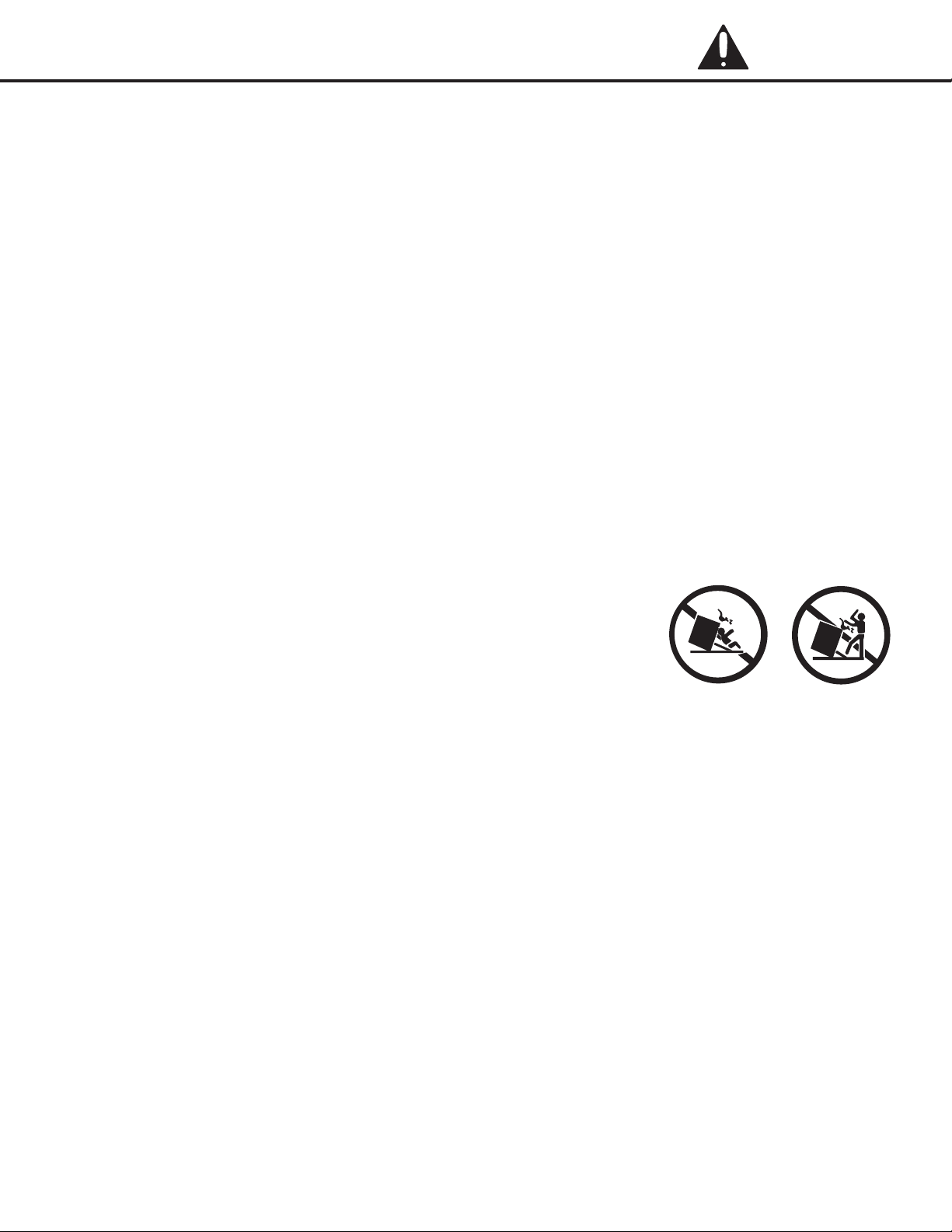
• Stepping,leaningorsittingonthisappliancecanresultin
serious injuries and also cause damage to the appliance.
• Never use this appliance as a space heater to heat
or warm the room. Doing so may result in carbon
monoxide poisoning and overheating.
• Knowwhichknobcontrolswhichsurfaceburner.Visually
check that the burner has lit. Then adjust the ame so it
does not extend beyond the edge of the pot/pan.
• Cleantheapplianceregularlytokeepallpartsfreeof
grease that could catch re. Exhaust fan ventilation
hoods and grease lters should be kept clean. Do not
allow grease to accumulate on hood or lter. Greasy
deposits in the fan could catch re. When cooking food,
turnthehoodfanon.Refertohoodmanufacturer’s
instructions for cleaning.
•
Pot/pan handles should be turned inward and not
extend over adjacent surface burners. To reduce the
risk of burns, ignition of ammable materials, and
spillage due to unintentional contact with the pot/pan,
the handle of the utensil should be positioned so that
it is turned inward, and does not extend over adjacent
surface burners.
• Neverleavesurfaceburnersunattendedathighheat
settings. Boilovers cause smoke and greasy spillovers
that may ignite, or a pan that has boiled dry may melt.
• Donotusealuminumfoiltolineanypartofthe
appliance. Use aluminum foil only to cover food during
cooking. Improper installation of these liners may result
in risk of electric shock or re.
• Onlycertaintypesofglass,glass/ceramic,ceramic,
earthenware, or other glazed utensils are suitable for
appliance service without breaking due to the sudden
changeintemperature.Checkthemanufacturer’s
recommendations for appliance use.
• Donotusedecorativesurfaceburnercovers.Ifa
burner is accidentally turned on, the decorative cover
will become hot and possibly melt. You will not be able
to see that the burner is on. Burns will occur if the hot
covers are touched. Damage may also be done to the
appliance or burners because the covers may cause
overheating. Air will be blocked from the burner and
cause combustion problems.
• Alwaysuseproperamesize.Adjustamesizesoit
does not extend beyond the edge of the pot/pan. The
use of undersized pots/pans will expose a portion of the
burner ame to direct contact and may result in ignition
of clothing. Proper relationship of pot/pan to ame will
also improve efciency.
• Topburneramesizeshouldbeadjustedsoitdoesnot
extend beyond the edge of the cooking utensil.
CALIFORNIA PROPOSITION 65 WARNING:
This product contains a chemical known to the state
of California to cause cancer, or birth defects or other
reproductive harm.
— 7 —
Important Safety Information
DANGER
• Usetheproperpot/pansizes.Thisapplianceis
equipped with surface units of different sizes. Select
pots/pans having at bottoms large enough to cover the
surface unit. The use of undersized utensils will expose a
portion of the surface heating unit to direct contact and
may result in ignition of clothing. Proper relationship of
utensil to the surface unit will also improve efciency.
• Donotusestovetopgrillsonyourgasappliance.Ifyou
use a stove top grill on a sealed gas burner, it will cause
incomplete combustion and can result in exposure
to carbon monoxide levels above allowable current
standards. This can be hazardous to your health.
• Removeallpackagingmaterialsfromtheappliance
before operating it. These materials can ignite, causing
smoke and/or re damage.
TIPPING DANGER
• TIPPINGRANGESCANCAUSESERIOUSPERSONALINJURYORDEATH.
• TOREDUCETHERISKOFTIPPINGOFTHERANGE,THERANGEMUSTBE
SECURED WITH A PROPERLY INSTALLED ANTI-TIP DEVICE.
• FAILURETOPROPERLYINSTALLTHEANTI-TIPBRACKETCOULDRESULTIN
THE DEATH OF A CHILD OR ADULT.
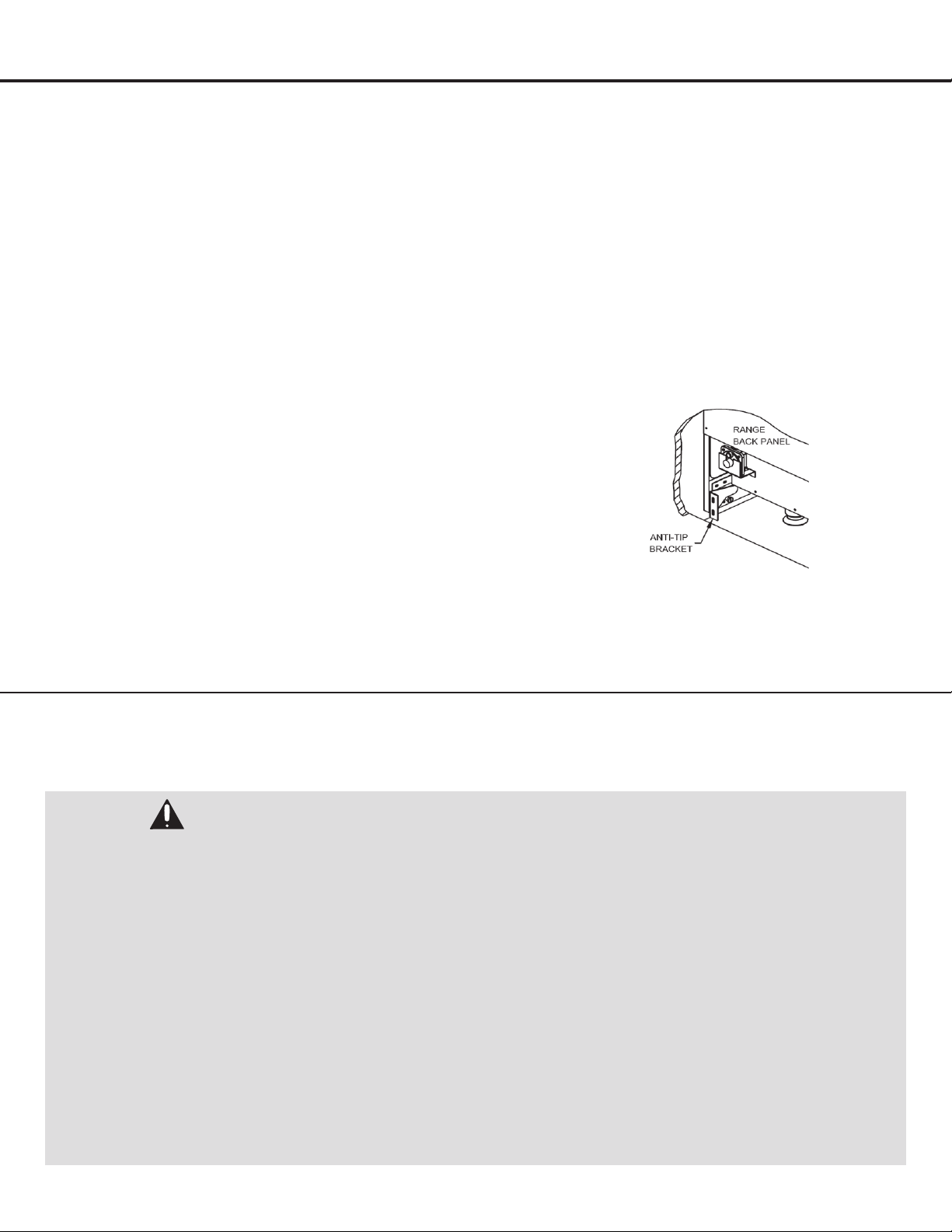
• Tocheckifthedevicehasbeenproperlyinstalled,sliderangeforward,lookforanti-tipbracketsecurelyattachedtooor
or wall then slide range back so rear range foot is under anti-tip bracket.
• Carefullypullontherangefromtherear.Ifthebracketisinstalledcorrectly,therangewillnottipmorethan4inchesfrom
the wall. If it tips forward more than 4 inches, the anti-tip device has not been has not been installed correctly.
• CAUTION:DONOTTIPTHERANGEMORETHAN4INCHESFROMTHEWALLASITCOULDTIPOVERANDCAUSE
INJURY.
• Iftherangeispulledfromthewallforanyreason,alwaysrepeatthisproceduretoverifytherangeisproperlysecured
by the anti-tip bracket.
• Nevercompletelyremovethelevelinglegsortherangewillnotbesecuredtotheanti-tipdeviceproperly.
• NEVERsteporsitonthedoor.
• Therangewillnottipduringnormaluse.However,withoutaproperlyfastenedanti-tipbracket,therangecantipiftoo
much force or weight is applied to the open door.
• Do not operate the range without the anti-tip bracket in place.
• Before removing label, ensure anti-tip bracket is properly installed.
• Seepage21forinstructionsonhowtoinstalltheAnti-TipBracket.
— 8 —
Important Safety Information
VENTILATION WARNINGS
• Theapplianceshouldhaveproperventilationinorder
to keep the unit operating properly and maintain the
temperature of immediate surroundings within safe
limits. Check your local building codes as they may vary
from the general rules outlined in this guide.
• Observeallgoverningcodesandordinances.Donot
obstruct ow of combustion and ventilation air.
• Itistheinstaller’sresponsibilitytocomplywith
installation clearances specied on the model/serial
rating plate.
• Forproperoperationofagasappliance,theair
necessary for the combustion of the gas must be able
to ow into the room naturally. The air must ow into
the room directly through openings in the outside walls.
These openings must have an unobstructed cross-
section not less than 2m3/h for each kw of power (see
total power in kw on the appliance).
• Thisopeningmustbeconstructedsothatitwill
not be obstructed from inside or outside, and not
be constructed close to the oor. The opening is
recommended to be on the side opposite to that on
which the ue gases are discharged.
•
The appliance should be located for convenient use
in the kitchen.
• Recessedinstallationsmustprovidecompleteenclosure
of the sides and rear of the range.
• It is recommended that the unit be operated with an
oven head, vented exhaust hood of sufcient size and
capacity.
• Toeliminatetheriskofburnsorrebyreaching
overheated surface units, cabinet storage space located
above the surface units should be avoided. If cabinet
storage is to be provided, the risk can be reduced by
installing a range hood or microwave hood combination
with minimum 600 CFM that projects horizontally a
minimum of 5” (12.7 cm) beyond the bottom of
the cabinets.
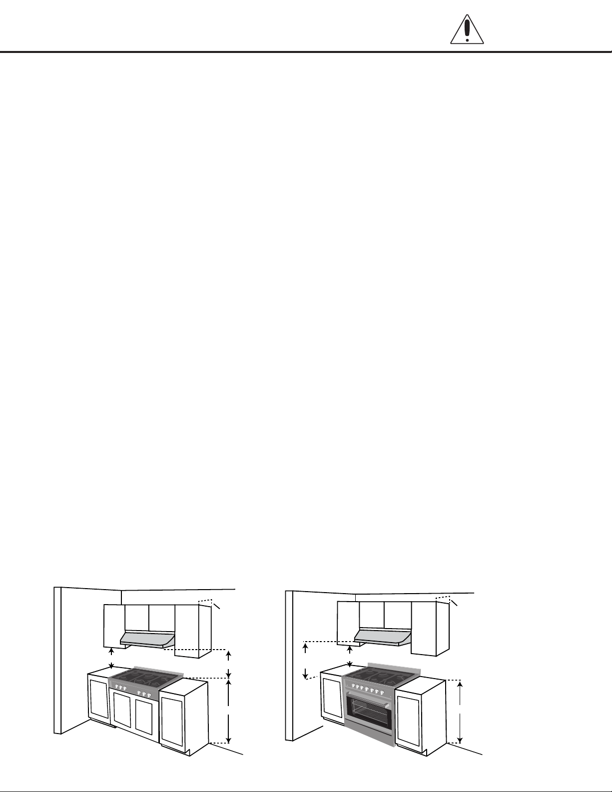
• Ifarangehoodisinstalledabovetheappliance,
maintain a 30” minimum clearance between cooking
surface and bottom of range hood. The range hood
must be connected directly to ues or to the outside.
• Avoidplacingcabinetrydirectlyabovetheappliance
when possible. If cabinetry is used above the cooking
surface, use cabinets no more than 13” deep. Make
sure the wall coverings, countertop and cabinets around
the appliance can withstand heat up to 200º F (93°C)
generated by the appliance.
• Cabinetopeningdimensionsthatareshownmustbe
used. Given dimensions are minimum clearances.
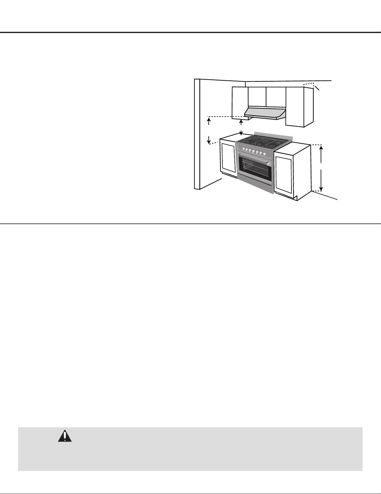
• Workingareasadjacenttotheapplianceshouldhave
18” minimum clearance between countertop and cabinet
bottom (see Figure 1).
• Allopeningsinthewalloroorwhereapplianceistobe
installed must be sealed.
• Contactaqualiedoorcoveringinstallertocheckthat
wall coverings, countertops and cabinets around the
appliance can withstand at least 200°F (93°C).
• Useaninsulatedpador1/4”(0.64cm)plywoodunder
range if installing range over carpeting.
• Theooranti-tipbracketmustbeinstalled.Toinstallthe
anti-tipbracketshippedwiththerange,see“InstallAnti-
Tip Bracket” section on page 21.
• Groundedelectricalsupplyisrequired.See“Connect
to AC” section on page 21, as well as the safety
precautions on page 10.
• Propergassupplyconnectionmustbeavailable.See
“GasConnection”sectiononpages17and18,aswell
as the safety precautions on page 9.
• It is the responsibility of the installer to make certain
that the appliance is properly adjusted at the time of
installation. Situations caused by improper adjustments
or improper installation are not covered under the
warranty.
30” (76.2 cm) Min.
18” (45.7 cm) Min.
13” (33 cm) Max.
36” (91.4 cm)
Figure 1
30”(76.2 cm)
Min.
18” (45.7 cm) Min.
13” (33 cm) Max.
36” (91.4 cm)
— 9 —
Important Safety Information
INSTALLATION WARNINGS
To avoid damage to your cabinets, check with your
builder or cabinet supplier to make sure that the
materials used will not discolor, delaminate or sustain
other damage.
MOBILE HOME – ADDITIONAL INSTALLATION
REQUIREMENTS:
The installation of this appliance must conform to the
Manufactured Home Construction and Safety Standard,
Title 24 CFR, Part 3280 (formerly the Federal Standard
for Mobile Home Construction and Safety, Title 24, HUD
Part 280).
When such standard is not applicable, use the Standard
for Manufactured Home Installations, ANSI A225.1/NFPA
501A, ANSI A119.2.2–1982, or with local codes.
In Canada, the installation of this range must conform
with the current standards CAN/CSA-A240-latest
edition, CAN/CGA Z240.4.2, or with local codes.
MOBILE HOME INSTALLATIONS REQUIRE:
When this range is installed in a mobile home, it must
be secured to the oor during transit. Any method of
securing the range is adequate as long as it conforms to
the standards listed above.
The installation of appliances designed for recreational
park trailers must conform with state or other codes
or, in the absence of such codes, with the standard for
recreational park trailers, ANSI A119.5.
GAS DANGER
Explosion hazard conditions will exist unless
you perform ALL of the following:
• UseanewCSAInternationalapprovedgas
supply line.
• Installashut-offvalve.
• Securelytightenallgasconnections.
• IfconnectedtoLP,haveaqualiedpersonmakesure
gas pressure does not exceed 10” (25 cm) (range
tops)/14” (36 cm) (ranges) water column.
• Examplesofaqualiedpersoninclude:
- Licensed heating personnel
- Authorized gas company personnel
- Authorized service personnel
Failure to do so can result in death, explosion, or re.
• Observeallgoverningcodesandordinances.
IMPORTANT: This installation must conform with all
local codes and ordinances. In the absence of local
codes, installation must conform with American National
Standard, National Fuel Gas Code ANSI Z223.1 / NFPA
54. - latest edition, or CAN/CGA B149 - latest edition. In
Canada, installation must conform to the current natural
Gas Installation /code, CAN 1-1.1-M81 and with local
codes where applicable. This appliance has been design-
certied according to ANSI Z21.1b-201 latest edition.
A statement of the maximum gas supply pressure in
accordance with the inlet pressure rating of the gas
appliance pressure regulator supplied.
IMPORTANT: Leak testing of the appliance must be
conductedaccordingtothemanufacturer’sinstructions.
• Theapplianceshouldbeconnectedtothesupplyline
with 1/2-inch black iron pipe or a certied exible type
stove connector. To prevent gas leaks, put an approved
sealing compound which is resistant to liqueed
petroleum gases on all threaded connections.
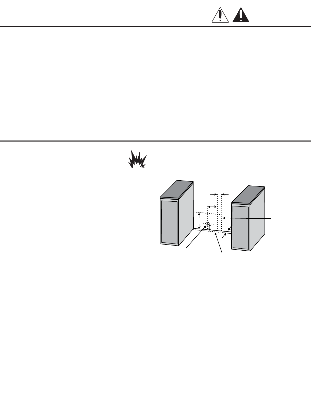
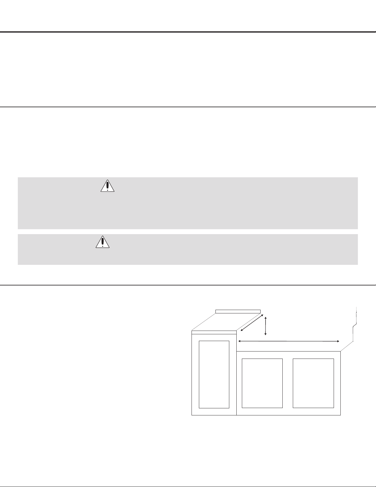
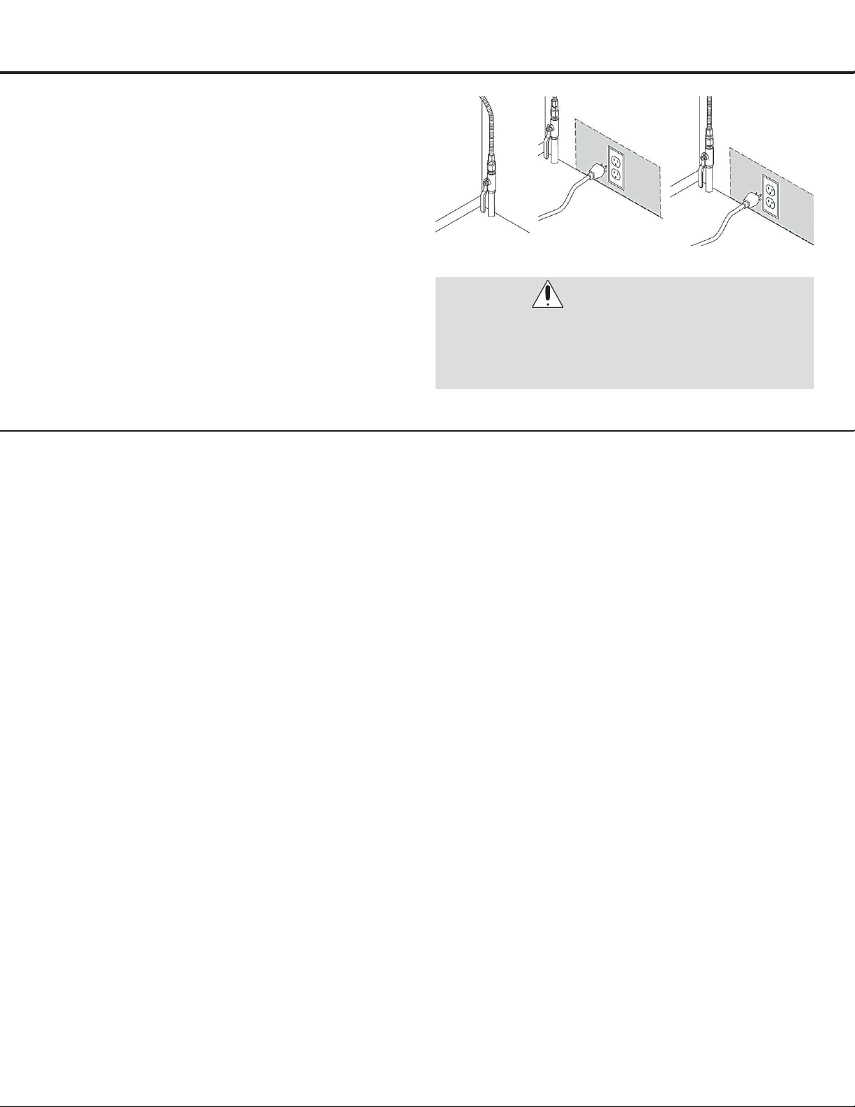
• Gassupply should be located near the opening for this
appliance (see Figure 2, ranges only):
Types of Gas
NATURAL GAS:
• ThisapplianceisdesignedforusewithNaturalgasor,
after proper conversion, for use with LP gas.
• ThisapplianceisfactorysetforusewithNaturalgas.The
model/serial rating plate has information on the types
of gas that can be used. If the types of gas listed do not
include the type of gas available, check with the local
gas supplier.
LP GAS CONVERSION:
•
Conversion must be done by a qualied service technician.
• Noattemptshallbemadetoconverttheappliancefrom
the gas specied on the model/serial rating plate for
use with a different gas without consulting the serving
gas supplier.
2”
4”
10.5”
2”
6.25”
Figure 2
Area allows for
ush installation
with through-the-
wall connection
of pipe stub /
shut-off valve
and rear wall
120V outlet.
Area allows for ush installation
with through-the-oor connection
of pipe stub / shut-off valve.
Shortest connection
from hard pipe stub
location to range
hook-up.
— 10 —
Important Safety Information
GAS CONNECTIONS (All Units)
Important: Do not apply pressure directly to the appliance
manifold pipe when tightening supply connections. The
manifold pipe should be held securely at the pressure
regulator to prevent twisting. Hold the pressure regulator
with a wrench during the tightening of the connection, or
the manifold pipe may be twisted and split and cause a
dangerous leak.
Note: Check all piping connections in the unit for leaks.
Never use an open ame to check for gas leaks. Use a soap
solution, 75% water, 25% dish washing soap. It is possible
for connections made at the factory to leak, due to vibration
encountered in transportation. Make certain you have
checked them all, and repair any connections that leak.
• Theapplianceanditsindividualshut-offvalvemustbe
disconnected from the gas supply piping system during
any pressure testing of that system at test pressures in
excess of 1/2 psig.
• Theappliancemustbeisolatedfromthegassupply
piping system by closing its individual manual shut-off
valve during any pressure testing of the gas supply piping
system at test pressures equal to or less than 1/2 psig.
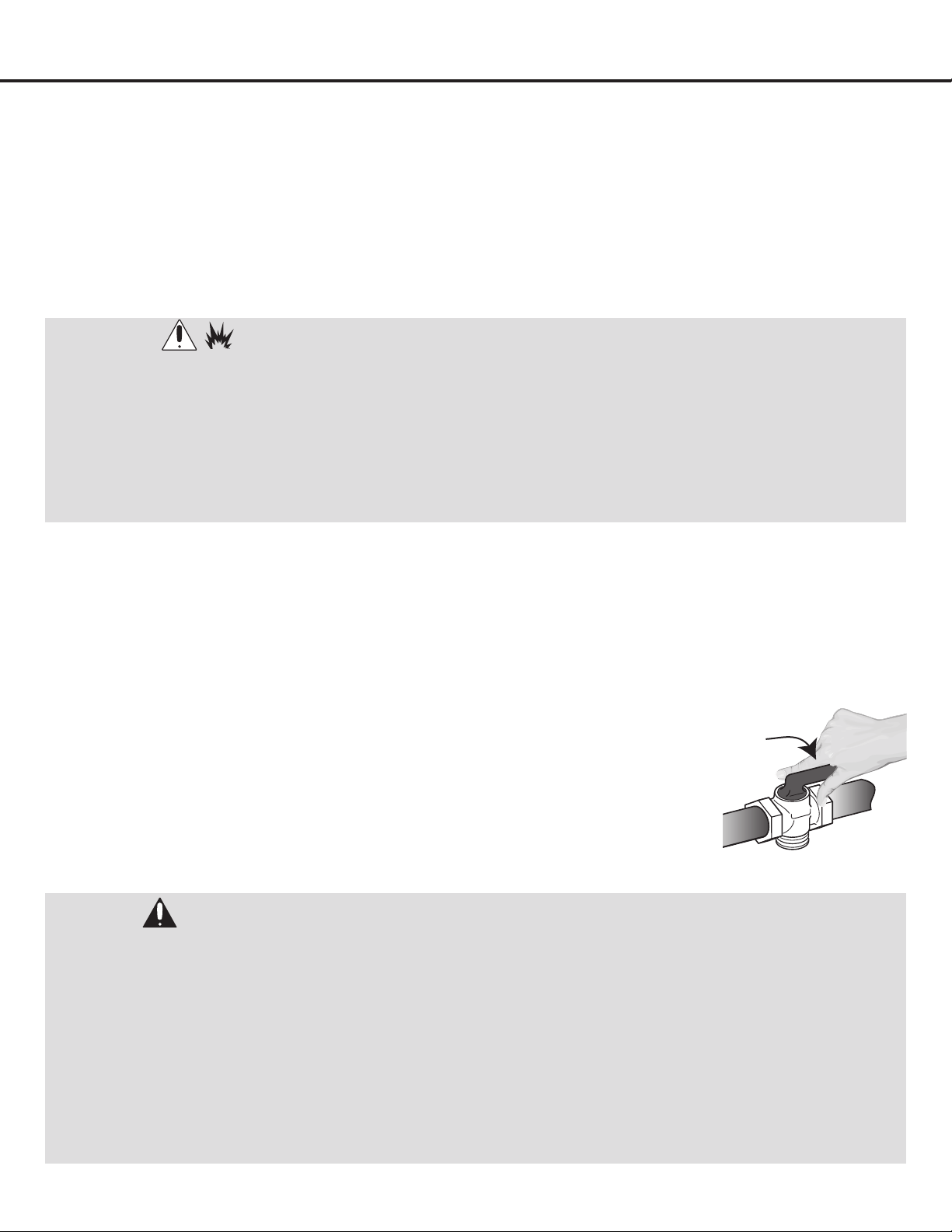
GAS LINE SHUT-OFF VALVE
• Toreducethepossibilityofgasleaks,applyTeontape
or a thread compound approved for use with LP or
Natural gases to all threaded connections.
• Installamanualgaslineshut-offvalveinthegasline
in an easily accessed location outside the range in the
gas piping external to the appliance for the purpose of
turning on or shutting off gas to the appliance.
• Installmale1/2’’(30-or36-inchrangetop)or3/4”(48
inchrangetop)areunionadapterto1/2”or3/4’’NPT
internal thread elbow at inlet of regulator. Use a wrench
on the regulator tting to avoid damage.
• Install male 1/2” or 3/4” are union adapter to the NPT
internal thread of the manual shut-off valve, taking care
to secure the shut-off valve to keep it from turning.
ELECTRICAL DANGER
Electrical Shock Hazard.
Do not use an extension cord.
Failure to follow these instructions can result in death,
re, or electrical shock.
• Anyadditions,changesorconversionsrequiredinorder
for this appliance to satisfactorily meet the application
needs must be made by a qualied service technician
inaccordancewiththemanufacturer’sinstructions
and all codes and requirements of the authority having
jurisdiction. Failure to follow the instructions could
result in serious injury or property damage. The qualied
agency performing this work assumes responsibility for
the conversion.
• DONOToperatethisapplianceusinga2-prongadapter
or an extension cord. If a 2-prong wall receptacle is the
only available outlet, it is the personal responsibility
of the consumer to have it replaced with a properly
grounded 3-prong wall receptacle installed by a
qualied electrician.
• Severeshock,ordamagetotherangemayoccurif
the appliance is not installed by a qualied installer or
electrician.
• Thisapplianceis120V/60Hz.Itisrecommendedto
connect to a 15-Amp or 20-Amp power supply.
• TotalInputPoweris14.1kW(AN-2160),20.8kW(AN-
2161), 27.5 kW (AN-2162), 3 A for range tops. Total
Input Power is 23.4 kW (AN-2230SS/BK/WHT), 30.2
kW (AN-2236SS/BK/WHT), 41.1 kW (AN-2248SS/BK/
WHT), 5 A for ranges. A dedicated circuit, protected by a
minimum 15 to 20-amp time delay fuse or circuit breaker
is required.
• Forpersonalsafety,theappliancemustbeproperly
grounded.
• The power supply must be the correct polarity. Reverse
polarity will result in continuous sparking of the
electrodes, even after ame ignition. If there is any doubt
as to whether the power supply has the correct polarity
or grounded, have it checked by a qualied electrician.
WARNINGS:
• ElectricalGroundingInstructions:thisindoorgas
cooking appliance is equipped with a three-prong
(grounding) plug for your protection against shock
hazard and should be plugged directly into a properly
grounded three-pronged receptacle.
• Donotcutorremovethegroundingprongfromthe
plug.
• Caution: label all wires prior to disconnection
when servicing controls. Wiring errors can cause
improper and dangerous operation. Verify proper
operation after servicing.
— 11 —
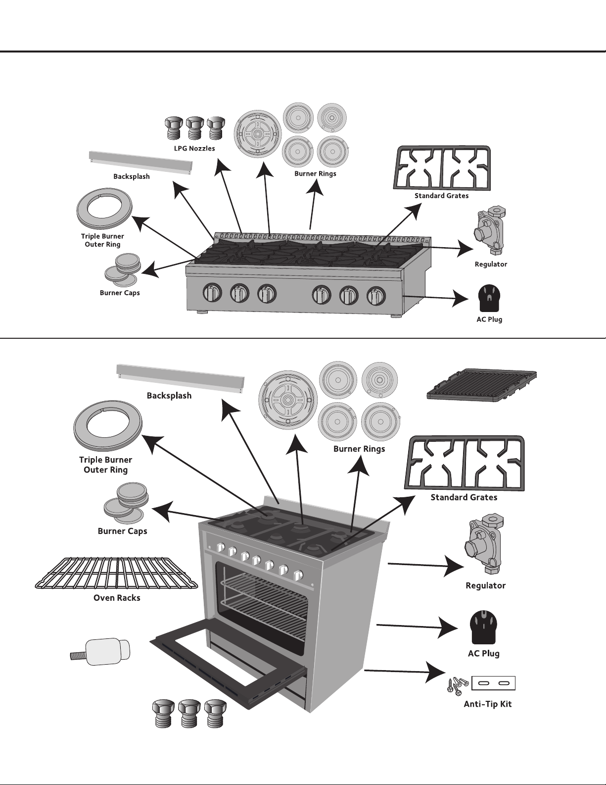
Adjustable Feet
Gas pipe adapter with washer
Griddle (48” models only)
LPG nozzles
Installation
Included Parts
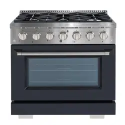
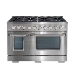
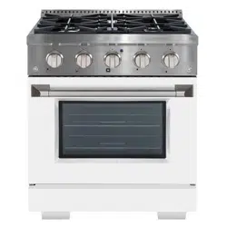
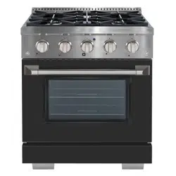
Range Top
Range
— 12 —
Installation
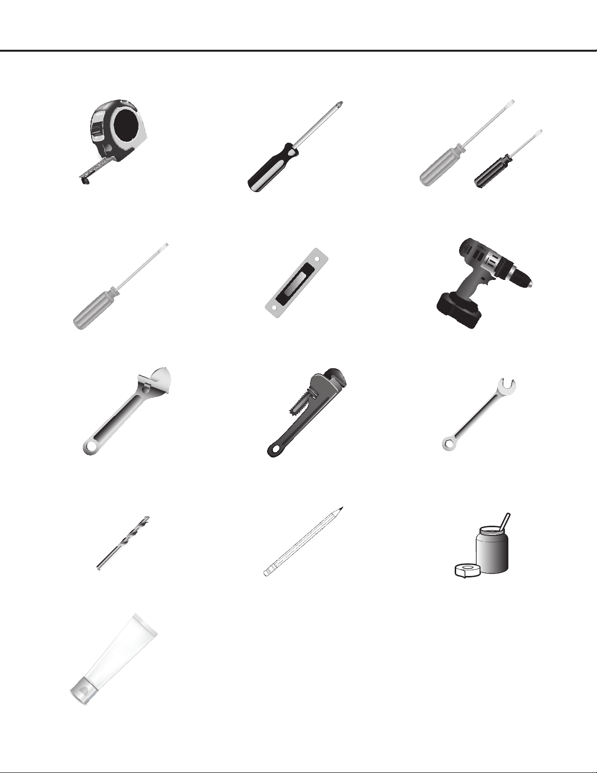
Tools and Additional Parts Needed
Tape measure Phillips screwdriver Flat blade screwdriver
1/8” at blade screwdriver
Hex screwdriver Level Hand or electric drill
Wrench or pliers Pipe wrench 15/16” combination wrench
1/8” (3.2 mm) drill bit (for wood oors) Marker or pencil
Pipe-joint compound resistant to
LP gas
For Additional Parts:
Check local codes, consult gas
supplier and check existing gas/
electricalsupply.See“Electrical
Requirements”and“GasSupply
Requirements” sections.
Noncorrosive leak-detection solution
— 13 —
Installation
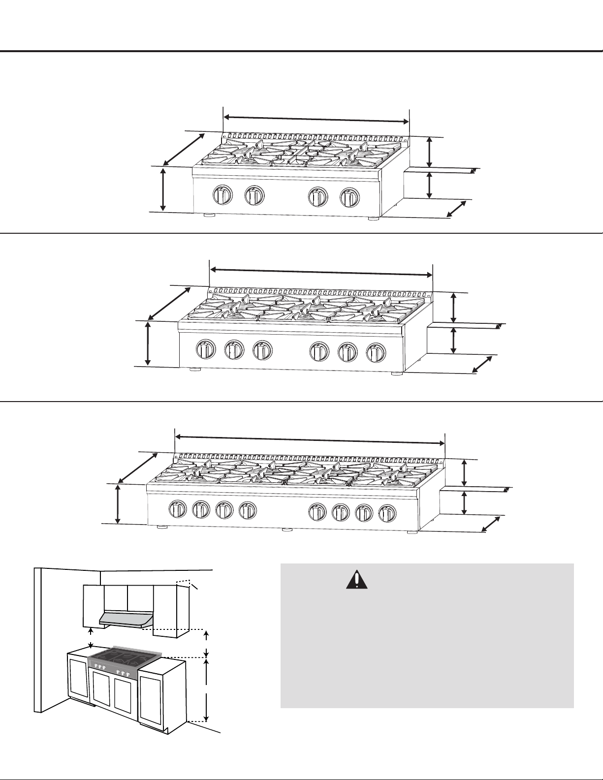
Range Top Dimensions
DANGER:
• Makesurethewallcoverings,countertopandcabinets
around the appliance can withstand heat up to 200º F
(93°C) generated by the appliance.
• Cabinetopeningdimensionsthatareshownmustbe
used. Given dimensions are minimum clearances.
• Workingareasadjacenttotherangetopshouldhave
18” minimum clearance between countertop and
cabinet bottom.
• SeeFigure4.
Figure 4
30” (76.2 cm) Min.
18” (45.7 cm) Min.
13” (33 cm) Max.
36” (91.4 cm)
30” (76.2 cm)
27.25”
(69.2 cm)
7.5”
(19.1 cm)
30” (76.2 cm)
9”
(22.9 cm)
26.5” (67.3 cm)
1.75”
(4.4 cm)
1.75”
(4.4 cm)
5”
(12.7 cm)
4.25”
(10.8 cm)
5.25”
(13.3 cm)
20.75”
(52.7 cm)
36” (91.4 cm)
27.25”
(69.2 cm)
7.5”
(19.1 cm)
5”
(12.7 cm)
4.25”
(10.8 cm)
5.25”
(13.3 cm)
20.75”
(52.7 cm)
36” (91.4 cm)
9”
(22.9 cm)
32.5” (82.5 cm)1.75”
(4.4 cm)
1.75”
(4.4 cm)
48” (121.9 cm)
27.25”
(69.2 cm)
7.5”
(19.1 cm)
5”
(12.7 cm)
4.25”
(10.8 cm)
5.25”
(13.3 cm)
20.75”
(52.7 cm)
48” (121.9 cm)
9”
(22.9 cm)
22.25” (56.5 cm)1.75”
(4.4 cm)
1.75”
(4.4 cm)
22.25” (56.5 cm)
AN-2160
AN-2161
AN-2162
— 14 —
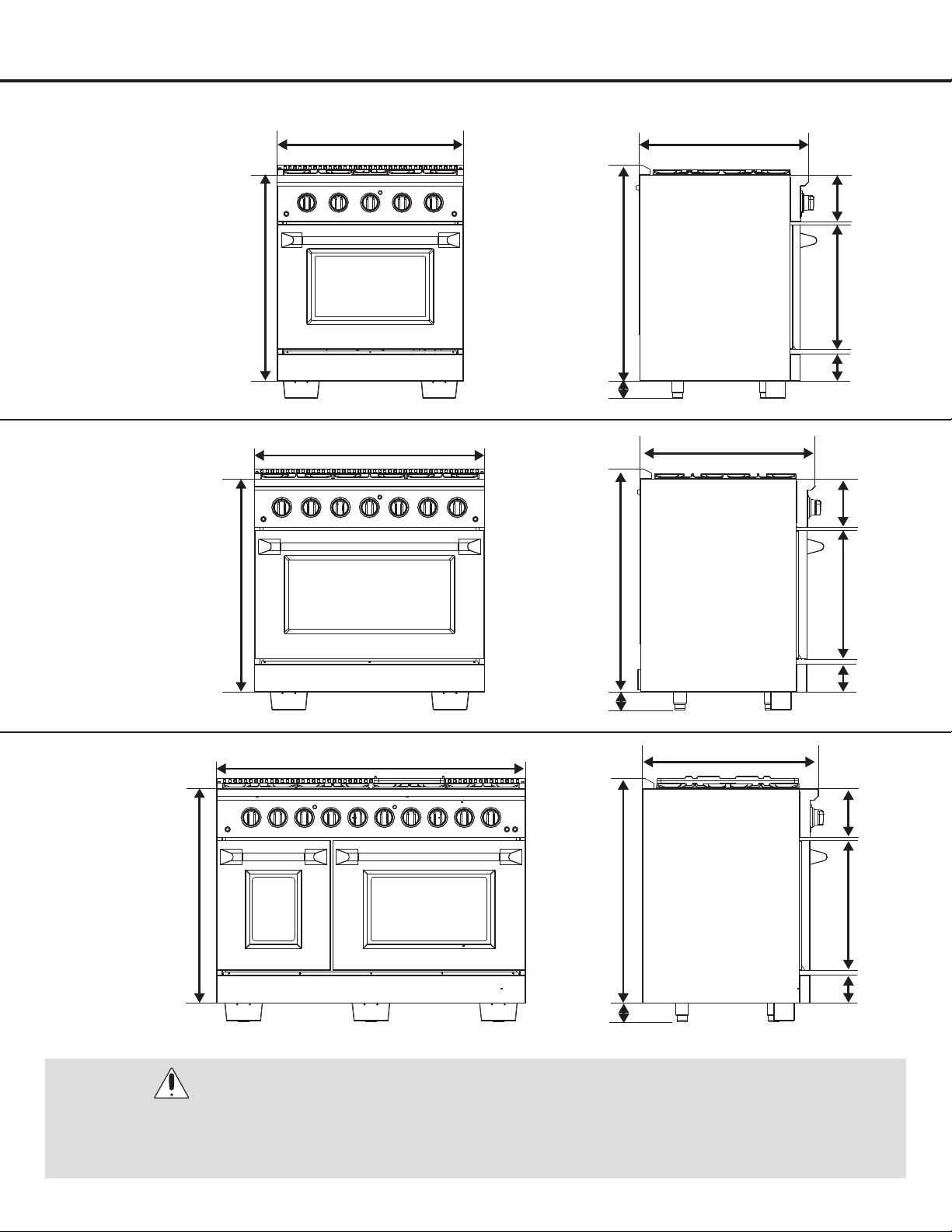
47.9” (121.7 cm)
27.3” (69.4 cm)
7.5”
(19.2 cm)
20.”1
(51.1 cm)
4.3”
(11 cm)
34.8”
(88.4 cm)
33.2”
(84.4 cm)
36” (91.5 cm)
33.2”
(84.4 cm)
27.3” (69.4 cm)
7.5”
(19.1 cm)
20.”1
(51.1 cm)
4.3”
(11 cm)
34.8”
(88.4 cm)
30” (76.3 cm)
33.2”
(84.4 cm)
34.8”
(88.4 cm)
27.3” (69.4 cm)
7.5”
(19.1 cm)
20.”1
(51.1 cm)
4.3”
(11 cm)
2.8” (7.2 cm) -
4” (10.2 cm)
2.8” (7.2 cm) -
4” (10.2 cm)
2.8” (7.2 cm) -
4” (10.2 cm)
Installation
Range Dimensions
AN-2230SS
AN-2230SSBK
AN-2230WHT
AN-2236SS
AN-2236SSBK
AN-2236WHT
AN-2248SS
AN-2248SSBK
AN-2248WHT
WARNING:
The use of cabinets for storage above the appliance may result in a potential fire hazard. Combustible items may ignite;
metallic items may become hot and cause burns. If a cabinet storage is to be provided, the risk can be reduced by
installing a range hood that projects horizontally a minimum of 5” (12.7 cm) beyond the bottom of the cabinets.

— 15 —
Installation
GAS RANGE TOP SPECIFICATIONS
Installation
Note: Minimum clearance for back wall is 0” with backsplash (backguard) or high shelf.
• If a range hood is installed above the range top, maintain a 30” (76.2 cm) minimum clearance between the range top
and the bottom of the range hood.
• The range top should only be used with ducted range hoods.
• For best smoke elimination, the minimum clearance of the range hood should be installed 30” to 36” above the range
top surface. Recommended CFM should be 600 CFM for the 30” range top.
• Do not install with a downdraft ventilation system.
The range top CANNOT be installed directly adjacent to sidewalls, tall cabinets, tall appliances, or other side vertical
surfaces above 36” (91.4 cm) high. There must be a minimum of 6” (15.2 cm) side clearance from the range top to such
combustible surfaces above the 36” (91.4 cm) counter height.
• Within the 6” (15.2 cm) side clearance to combustible vertical surfaces above 36” (91.4 cm), the maximum wall cabinet
depth must be 13” (33.0 cm) and wall cabinets within this 6” (15.2 cm) side clearance must be 18” (45.7 cm) above the
36” (91.4 cm) high countertop.
Installation in an island
Note: There must be a minimum of 6” (15.2 cm) clearance from rear of range top to a combustible wall. Clearances from
non-combustible materials are not part of the ANSI Z21.1 scope and are not certied by CSA. Clearances to non-combustible
materials must be approved by the authority having jurisdiction.
• This range top may be installed directly adjacent to existing 36” (91.4 cm) high base cabinets.
GAS RANGE SPECIFICATIONS
• Before installing the range, you must locate and secure the included anti-tip bracket to the wall for your range.
• The range may be installed ush to the rear wall. You may install a non-combustible material on the rear wall above
the range and up to the vent hood. It is not necessary to install non-combustible materials behind the range below the
countertop height.
• The minimum distance from the side of the range above the countertop to combustible sidewalls must be at least 10
inches.
WARNING:
• Itemsofinteresttochildrenshouldnotbeplacedincabinetsabovethecooktop.
• Childrenclimbingonthecooktoptoreachitemscouldbeseriouslyinjured.
— 16 —
STEP 1
Read the Safety Precautions
Please read the safety precautions on pages 4 to 10. Safety instructions pertaining to each step have been outlined in the
installation steps; however it is important to read ALL the safety instructions.
IMPORTANT: It is the installer’s responsibility to comply with installation clearances.
STEP 2
Plan Desired Location, Unpack the Appliance and Prepare Tools
Plan a desirable location that ts all requirements in the Safety and Install sections of this manual. Unpack the appliance
and parts carefully (all burners, burner caps and cooking grates). Make sure all parts are included as shown on page 11 and
set aside. Assemble all tools as shown on page 12. DO NOT remove the protective lm covering the appliance.
Installation
STEP 3A (range tops only)
Prepare Cut-Out
Cut the opening in the countertop. To ensure accuracy it
is best to make a template (see Figure 5) for the opening.
Make sure the sides are parallel also rear and front cuts are
exactly perpendicular to the sides. Observe all minimum
clearances.
• AN-2160 / 30-inch models (Length × Depth × Height):
30.5” × 26” × 7.5” (77.5 cm × 66 cm × 19.1 cm)
• AN-2161 / 36-inch models (Length × Depth × Height):
36.5” × 26” × 7.5” (92.7 cm × 66 cm × 19.1 cm)
• AN-2162 / 48-inch models (Length × Depth × Height):
48.5” × 26” × 7.5” (123.2 cm × 66 cm × 19.1 cm)
Height
Depth
Length
Figure 5
WARNINGS (ranges only):
• ExtremelyHeavy.
• Properequipmentandadequatemanpowerwhenmovetherangetoavoidpersonalinjuryordamagetotheunitor
the floor. The unit is heavy and rests on adjustable steel legs.
• Failuretofollowthisadvicemayresultindamageorpersonalinjury.
WARNING (ranges only):
DO NOT LIFT THE UNIT BY THE OVEN DOOR HANDLE.
— 17 —
STEP 4
Gas Connection
Range Tops:
This range top is designed to operate at a pressure of 4”
of water column on natural gas or 10” of water column on
propane gas (LPG).
This range top can be converted for use on Liquid propane
gas (LPG). When using this range top on LPG gas,
conversion must be made by a qualied installer before
attempting to operate the range top on that gas.
For correct operation, the pressure of natural gas supplied to
the regulator should be between 4” and 5” of water column.
For LP gas, the pressure supplied must be between 10” and
12” of water column.
When checking for correct operation of the regulator, the
inlet pressure must be at least 1” more than the operating
manifold pressure as given above.
Ranges:
For NG, input pressure is 7” W.C. and output pressure 5”
W.C.
For LP, input pressure is 11” W.C. and output pressure: 10”
W.C.
Appliance regulator is set at 5.0” W.C. outlet pressure.
The gas supply pressure for checking the regulator setting is
5” (Natural Gas) and 10” (LP gas). Connect exible gas line
connector to the regulator on the range. Position range to
permit connection at the shut off valve.
DANGER:
The gas supply line must be equipped with an approved manual shut-off valve. The shut-off valve must be in an easily
accessible location in the same room as the appliance. Do not block access to the shut-off valve. Be sure you know
how and where to shut off the gas supply to the range.
STEP 3B (ranges only)
Dimensions and Clearances
• Before installing the range, you must locate and secure
the included anti-tip bracket to the wall for your range.
• The range may be installed ush to the rear wall. You
may install a non-combustible material on the rear
wall above the range and up to the vent hood. It is not
necessary to install non-combustible materials behind
the range below the countertop height.
• The minimum distance from the side of the range above
the countertop to combustible sidewalls must be at
least 10 inches.
Installation
30”(76.2 cm)
Min.
18” (45.7 cm) Min.
13” (33 cm) Max.
36” (91.4 cm)
Figure 6
— 18 —
The pressure regulator located at the inlet of the appliance manifold must remain in the supply line regardless of Natural
(NG) or Liquid Propane (LP) gas is being used.
A exible metal appliance connector used to connect the appliance to the gas supply should be 3 feet/91.4 cm max. in
length for easy installation. In Canada, exible connectors should be single wall metal connectors less than 6 feet/182.9 cm
in length.
Installation
STEP 4 (Continued)
Gas Connection
DANGER:
• PleasemakesuretoreadALLsafetyprecautionsonpages4to10.
•
Do not use a flame to check for leaks from gas connections. Checking for leaks with a flame may result in a
fire or explosion.
• Tightenallconnectionsifnecessarytopreventgasleakageintheapplianceorsupplyline.
• Checkalignmentofcontrolknobvalvesafterconnectingtheappliancetothegassupplytobesuretheappliance
manifold pipe has not moved. A misalignment could cause the valve stems to rub on the control panel, resulting in
a gas leak at the valve.
• Disconnectthisapplianceanditsindividualmanualshut-offvalvefromthegassupplypipingsystemduringany
pressure testing of that system at test pressures in excess of 1/2 psi (3.5 kPa or 12” water column).
•
Isolate the appliance from the gas supply piping system by closing its individual manual shut-off valve during any
pressure testing of the gas supply piping system at test pressures equal to or less than 1/2 psi (3.5 kPa or 12” water
column).
Figure 7
u
Shut off the main gas supply valve before removing
the old cooking appliance (if applicable) and leave it
offuntilthenewhook-uphasbeencompleted.Don’t
forget to relight the pilots on other gas appliances
when you turn the gas back on.
v
Because hard piping restricts movement of the
appliance, the use of a CSA certied exible metal
appliance connector is recommended unless local
codes require a hard-piped connection. Never reuse
an old connector when installing a new appliance. If
the hard piping method is used, you must carefully
align the pipe.
To prevent gas leaks, use pipe joint compound
resistant to NG gases on all male external pipe
threads.
w
Use a exible gas line to connect to the 1/2” tting,
located on the bottom right hand corner underneath
the appliance.
x
When all connections have been made, be sure all
appliance controls are in the off position and turn
on the main gas supply valve. Check for gas leaks
by using a 75% water,
25% dish washing soap
solution. If a gas leak
occurs, shut off gas
immediately, tighten all
connections, and retest
for leaks.
WARNINGS:
• PleasemakesuretoreadALLsafetyprecautionsonpages4to10.
• ExplosionHazard.
• UseanewCSAInternationalapprovedgassupplyline.
• Installashut-offvalve.
• Securelytightenallgasconnections.
• IfconnectedtoLP,haveaqualifiedpersonmakesuregaspressuredoesnotexceed12”(30cm)watercolumn.
Examples of a qualified person include: licensed heating personnel, authorized gas company personnel, and
authorized service personnel.
• Failuretodosocanresultindeath,explosion,orfire.
— 19 —
Installation
STEP 5 (Optional)
(Must be done before Step 6 if converting to Propane)
Liqueed Petroleum (Propane)
Gas Conversion
This appliance can be used with Natural Gas or LP/Propane
Gas. It is shipped from the factory for use with Natural Gas. A
kit for converting to LP gas is supplied with your appliance.
Thekitismarked“FORLP/PROPANEGASCONVERSION”.
u
When the appliance is converted for Liquid Petroleum
(LP) Gas, the LP gas supply is required to provide a
minimum of 10” to a maximum of 12” water column to
the appliance regulator.
Following LP Gas
Conversion, complete
steps:“Adjustingthe
Regulator Pressure”;
“ChangingBurner
Nozzles”;“Adjusting
Burner Flames”; and
“TestingFlameStability”
.
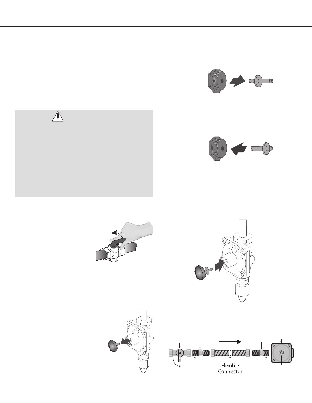
Adjusting the Regulator Pressure
v
Shut off the gas supply to
the appliance by closing
the manual shut-off valve
(see Figure 8). Disconnect
electrical power to the
appliance before servicing. Do
not remove regulator or allow
it to turn during servicing.
w
Unscrew the regulator cap with a wrench (see Figure
9).
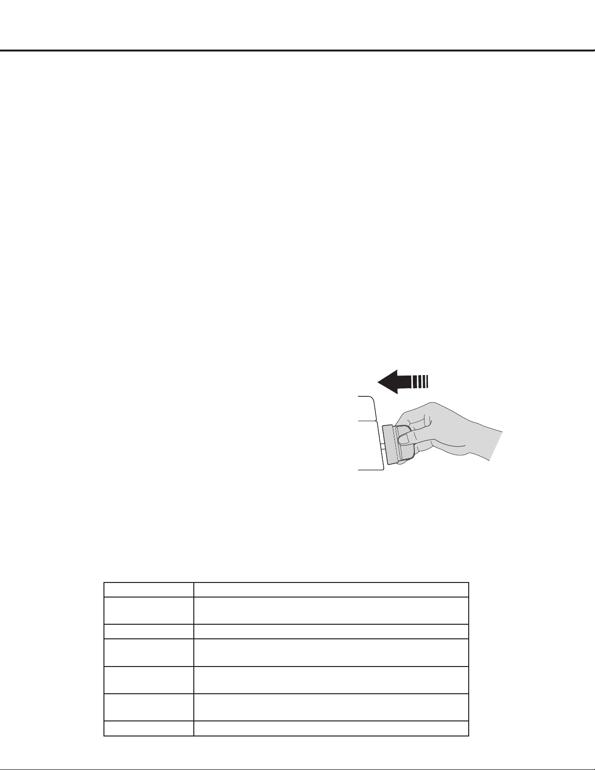
x
Remove retainer pin by pulling it out (see Figure 10).
y
Reverse the retainer pin and snap it back into the
regulator cap (see Figure 11).
U
Screw the regulator cap back into the regulator and
re-attach it to the nipple and are union as shown.
DO NOT over-tighten (see Figures 12 and 13).
WARNINGS:
• PleasemakesuretoreadALLsafetyprecautionson
pages 4 to 10.
• Failuretomaketheappropriateconversionafter
Step 4 can result in serious personal injury and
property damage.
•
The conversion must be performed by a qualified
service technician in accordance with the kit instruc-
tions and all local codes and requirements. Failure
to follow instructions could result in serious injury or
property damage. The qualified agency performing this
work assumes responsibility for the conversion.
Joint Joint
Off
On
Manual
Shut off
Valve
Pressure
Regulator
Flare
Union
Flare
Union
Gas Flow
Access
Cap
Figure 8
Figure 9
Figure 12
Figure 13
Figure 10
Figure 11
— 20 —
STEP 5 (Continued)
Liqueed Petroleum (Propane)
Gas Conversion
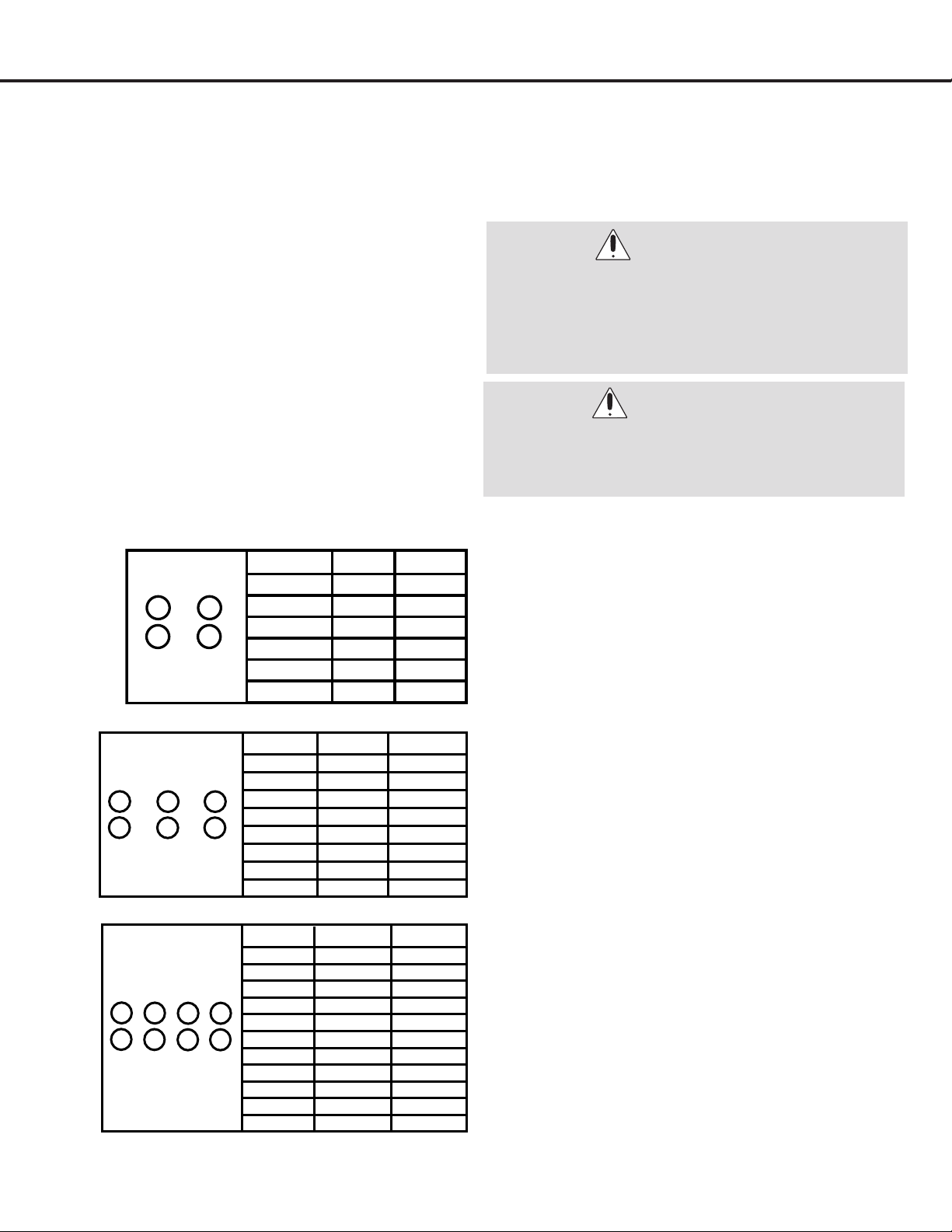
Changing Burner Nozzles
INSTALLATION TIP: To prevent any omissions,
remove ALL existing Natural Gas nozzles before
replacing them with the LP nozzles.
V
Remove the burner grates, burner caps and burner
rings. Using the a 7mm nut driver, remove ALL the
existing Natural Gas burner nozzles. Carefully read
and observe each nozzle label for correct location
(DO NOT force or over-tighten nozzles as doing so
will damage the burner base and affect the ame).
W
Install the proper nozzles in the exact locations as
noted in the illustrations below (see Figures 14).
Installation
Figure 14
WARNING:
Save the natural gas orifices removed from the
appliance for possible future conversions to natural
gas. You should use the following process to convert
to Natural gas. Take extra care when handling steel
parts.
WARNING:
Care should be taken when removing and replacing
gas components. Use proper support to prevent
damage to components.
1.16
0.9
1.16
0.9
LPG
NG
1.36
1.79
1.79
1.36
Burner
B
C
D
A
D
C
B
A
Broil
Oven
0.941.42
1.42.13
0.89*2+0.53
0.74
0.9
NG
1.57
1.36*2+0.73
1.07
1.36
Burner
B
C
D
A
LPG
1.0
D
C
B
A
F
E
1.161.79E
0.91.36F
Broil
Oven
0.941.42
1.42.13
Débit d'entrée du bruleur (BTU/h) / Burner input rating
0.74
0.9
NG
1.57
1.36*2+0.73
1.07
1.36
Burner
B
C
D
A
1.0
0.89*2+0.53
LPG
D
C
B
A
F
E
H
G
Broil
Oven
0.941.42
1.42.13
0.74
0.9
1.57
1.36*2+0.73
1.07
1.36
F
G
H
E
1.0
0.89*2+0.53
18” Oven 1.091.68
30”
36”
48”
— 21 —
Installation
STEP 7
Connect to AC
DANGER:
• PleasemakesuretoreadALLsafetyprecautionsonpages4to10.
• ElectricalShockHazard.
• Donotuseanadapter.
• Donotuseanextensioncord.
• Failuretofollowtheseinstructionscanresultindeath,fire,orelectricalshock.
• Electricalconnectionmustbeperformedbyaqualifiedservicetechnicianinaccordancewiththekitinstructions
and all local codes and requirements.
• Thesafetycircuit-breakerandtheelectricalsystemmustbeabletowithstandtheloadoftheappliance.Seerating
label on back of appliance.
•Ratingplateislocatedonbackofapplianceshouldyouneedtoverifyanyoftheelectricalrequirements.
•Thepowersupplysystemshouldhaveagroundconnectioningoodworkingorderinaccordancewiththe
regulations in force.
•
The electrical socket must be easily accessible with the appliance installed. In all cases, the power supply lead must
be positioned so that it does not reach a temperature of 50°C (122°F) above the room temperature at any point.
•Themanufacturerisnotliableforanydirectorindirectdamagecausedbyfaultyinstallationorconnection.Itis
therefore necessary that all installation and connection operations are carried out by qualified personnel, complying
with the local and general regulations in force.
STEP 6 (ranges only)
Install Anti-Tip Bracket
To reduce the risk of tipping of the range, the range must be
secured to the oor with a properly installed Anti-Tip Bracket
(included).
All ranges can tip and cause injuries. Install anti-tip device
packaged with range, follow all Installation Instructions.
Failure to install the Anti-Tip Bracket will allow the range
to tip over if excessive weight is placed on an open door
or if a child climbs upon it. Serious injury might result from
spilled hot liquids or from the range itself. If range is ever
moved to a different location, the Anti-Tip Bracket must be
re-installed.
Make sure the anti-tip bracket is installed:
u
Slide range forward.
v
Make sure the anti-tip bracket is securely attached
to the wall behind the range.
w
Safely tilt the front of the range upward slightly and
move back against wall, Making sure the pin slides
under bracket.
Figure 15
— 22 —
Installation
WARNING:
• Neverusereductions,shunts,oradapterswhich
can cause overheating or burning.
• MakesuretheACSupplycabledoesnotcomein
contact with any parts or components that get hot.
STEP 8A (range tops only)
Finish Installation
u
Gently slide in the range top half into the cut-out,
make sure your gas connection and electrical power
plug are properly installed.
v
Oncethisisdoneyou’renowreadytoslidethe
range top all the way back to the wall.
• Thepowercordisequippedwithathree-prong
(grounding) plug which mates with a standard three-
prong grounding wall receptacle to minimize the
possibility of electrical shock hazard from the appliance.
•Allcordconnectedapplianceshallincludeinstructions
relative to location of the wall receptacle and a warning
to the user to disconnect the electrical supply before
serving the appliance.
•Whereastandardtwo-prongwallreceptacleis
encountered, it is the responsibility and obligation of the
customer to have it replaced with a properly grounded
threeprong wall receptacle. Do not cut or remove the
grounding prong from the power cord.
Figure 16 Figure 17 Figure 18
w
Install all burners and burner caps.
x
Install all grates.
STEP 8B (ranges only)
Finish Installation
u
When all connections have been made, check that
allrangecontrolsareinthe“off”positionandturn
on the main gas supply valve.

— 23 —
Safety Before Operating
Safety Precautions
Before operating this appliance it is VERY important that
you read the safety precautions on pages 4 to 10 as well as
all safety precautions listed on this and the following pages
with the header, “Safety Before Operating”.
• Makesureyourapplianceisproperlyadjustedbya
qualied service technician or installer for the type of
gas (natural or LP) that is to be used. Your appliance
can be converted for use with either type of gas. See
the installation instructions section in this manual.
These adjustments must be done by a qualied service
technicianaccordingtothemanufacturer’sinstructions
and all codes and requirements of the authority having
jurisdiction. Failure to follow these instructions could
result in serious injury or property damage. The qualied
agency performing this work assumes responsibility for
the conversion.
• Itemsofinteresttochildrenshouldnotbeplacedin
cabinets above a appliance or on the backsplash of
appliance—children climbing on the appliance to reach
items could be seriously injured.
•
DO NOT leave children alone or unattended where appliance
is hot or in operation. They could be seriously burned.
•
DO NOT let anyone climb, stand or hang on the cooktop.
They could damage the range or cause it to tip over which
could result in severe personal injury.
• NEVERuseyourapplianceasaspaceheatertoheator
warm the room. Doing so may result in carbon monoxide
poisoning and overheating of the oven.
• NEVERwearloosettingorhanginggarmentswhile
using the appliance. Be careful when reaching for items
placed in cabinets over the appliance. Flammable
material could be ignited if brought in contact with ame
or hot oven surfaces and may cause severe burns.
• DO NOT place ammable materials in an oven,
a warming drawer or near a cooktop.
• DO NOT place or use combustible materials such as
gasoline or other ammable vapors and liquids in the
vicinity of this or any other appliance.
• DO NOT allow cooking grease or other ammable
materials in or near the appliance.
• DO NOT use water on grease res. Never touch a aming
pan. Turn the controls off. Smother a aming pan on
a surface burner by covering the pan completely with
a well-tting lid, cookie sheet or at tray. A grease re can
be put out by covering it with baking soda or, if available,
by using a multi-purpose dry chemical or foam-type
re extinguisher. Flame in the upper oven or lower oven
drawer can be smothered completely by closing the oven
door or drawer and turning the control to off, or by using a
multi-purpose dry chemical or foam-type re extinguisher.
• Allowtheburnergratesandothersurfacestocoolbefore
touching them.
• NEVERblockthevents(airholes)oftheappliance.They
provide the air inlet and outlet that are necessary for
the appliance to operate properly with correct
combustion.
• Stepping,leaningorsittingonthisappliancecanresultin
serious injuries and also cause damage to the appliance.
DO NOT allow children to climb or play around the
appliance. The weight of a child may cause the appliance
to tip, resulting in serious burns or other injury.
• Leaktestingoftheapplianceshallbeconducted
accordingtothemanufacturer’sinstructions.
• Makesureyourapplianceisproperlyinstalledand
grounded by a qualied installer, according to the
installation instructions. Any adjustment and service
should be performed only by qualied gas range
installers or service technicians.
• Topreventpooraircirculation,placetheapplianceout
of kitchen trafc path and out of drafty locations.
•DO NOT attempt to repair or replace any part of your
appliance unless it is specically mentioned in this
manual.
All other service should be referred to a qualied
technician.
•Makesureallpackagingmaterialsareremovedfromthe
appliance before operating it to prevent re or smoke
damage should the packaging material ignite.
• When cooking, set the burner controls so that the ame
heats only the bottom of the utensil and does not overlap
at the sides of the utensil.
• Utensils (pots and pans) that conduct heat slowly, i.e.
glass pots, should be used in conjunction with burner
ames at a low or medium setting.
• Turn off all controls and wait for appliance parts to cool
down before touching them. Do not touch the burner
grates or surrounding areas until cool.
• Use the appliance only for cooking tasks as outlined in
this manual. When using the appliance, do not touch the
grates, burner caps, burner bases, or any other parts in
proximity to the ame. These components may be hot
enough to cause burns.
• During and after use, do not touch interior surfaces of the
oven until cool.
— 24 —
Safety Before Operating
Surface Burner Safety
• NEVERleavethesurfaceburnersunattendedathigh
ame settings. Boilovers cause smoking and greasy
spillovers that may catch on re.
•AlwaysturntheburnerknobtotheIgnite position when
igniting the top burners and make sure the burners
have ignited.
•Controlthetopburneramesizesoitdoesnotextend
beyond the edge of the cookware. Excessive ame is
hazardous.
•Useonlydrypotholders—moistordamppotholders
on hot surfaces may result in burns from steam. DO
NOT let pot holders come near open ames when lifting
cookware. DO NOT use a towel or other bulky cloth
instead of a pot holder.
•Whenusingglasscookware—makesureitisdesigned
for top-of-range cooking.
•Topreventburns,ignitionofammablematerialsand
spillage, cookware handles should be turned toward the
side or back of the appliance and should not extend over
adjacent burners.
•
NEVER place any items on the cooktop. The hot air
from the vent may ignite ammable items and will
increase pressure in closed containers, which may
cause them to burst.
•Carefullywatchfoodsbeingfriedatahighamesetting.
•Alwaysheatfatslowly,andwatchasitheats.
•Iffryingcombinationsofoilsandfats,stirtogether
before heating.
•Useadeepfatthermometerifpossibletoprevent
overheating fat beyond the smoking point.
•Usetheleastpossibleamountoffatforeffectiveshallow
or deep-fat frying. Filling the pan too full of fat can cause
spillovers when food is added.
•DO NOT cook foods directly on the ame (without a pot
or pan), use proper cookware.
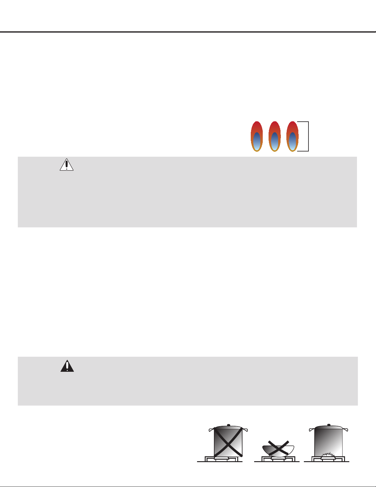
•DO NOT use a wok on the surface burners if the wok has
a round metal ring that is placed over the burner grate
to support the wok. This ring acts as a heat trap, which
may damage the burner grate and burner ring. Also, it
may cause the burner to work improperly and may cause
a carbon monoxide level above that allowed by current
standards, resulting in a health hazard.
•Foodsforfryingshouldbeasdryaspossible.Frostor
moisture on foods can cause hot fat to bubble up and
spill over the sides of the pan.
•NEVERtrytomoveapanofhotfat,especiallyadeepfat
fryer. Wait until the fat is cool.
•DO NOT place plastic items on the cooktop—they may
melt if left too close to the vent.
•Keepallplasticsawayfromthesurfaceburners.
•Topreventburns,alwaysbesurethattheBurnerknobs
are in the OFF position and all grates are cool before
attempting to remove them.
•Ifyousmellgas,turnoffthegastotheapplianceandcall
a qualied service technician. Never use an open ame
to locate a leak.
•AlwaysturnBurnerknobtotheOFFpositionbefore
removing cookware.
•DO NOT lift the cooktop. Lifting the cooktop can cause
damage and improper operation of the appliance.
•Ifapplianceislocatednearawindow,DO NOT hang long
curtains that could blow over the surface burners and
catch on re.
• DO NOT operate the burner for an extended period of
time without cookware on the grate. The nish on the
grate may chip without cookware to absorb the heat.
• Alwaysuseutensils/cookwarefortheirintendedpurpose.
Followmanufacturer’sinstructions.Someutensils/
cookware were not made to be used in the oven or on the
cooking surface.
READ AND FOLLOW THIS SAFETY
INFORMATION CAREFULLY.
SAVE THESE
INSTRUCTIONS!
WARNINGS:
• Ifthetopburneramegoesout,gaswillcontinue
to ow to the burner until the knob is turned to the
OFF position.
• DonotleavetheburnersONunattended.
• Useproperpot/pansize—DONOTusepansthat
are unstable or easily tipped. Select cookware
having at bottoms and large enough to cover
burner grates. To avoid spillovers, make sure
cookware is large enough to contain the food
properly. This will save both cleaning time and
prevent hazardous accumulations of food which
could ignite if left on the appliance. Use pans with
handles that can be easily grasped and remain
cool.
— 25 —
Operation
•Therearedualburnersthathavethesamelowturn-down
setting (SIM) for gentle simmering (620 BTU/hr). Use the
SIM setting for melting chocolate and butter, cooking rice
and delicate sauces, simmering soups and stews, and
keeping cooked food hot.
•Never leave the appliance unattended when in use.
Boil over causes smoking and greasy spills that may
ignite.
•Neverallowamestoextendbeyondcookwareorcurlup
its sides. This could discolor and damage the utensil and
you may get burned touching a hot handle.
•Keephandlesoutoftheway.Turnhandlessothatthey
don’textendovertheedgeoftheapplianceoranother
burner that is on.
•Takecarewhendeep-frying.Oilorfatcanoverheatvery
quickly, particularly on a high setting.
•Makesurethatallburnerpartsareproperlyinplace.
Incorrectly or incompletely assembled burners may
produce dangerous ames. See ‘Replacing the burner
parts’in‘Careandcleaning’.
•Keeptheburnersclean.Especiallyafteraspillorboil
over, make sure you clean the affected burners before
using them again. Food residue may clog the igniter and
the notches of the ame spreader, stopping the burner
fromfunctioningcorrectly.See‘Careandcleaning’for
instructions.
•Checkthattheburneramesareregular.Theyshouldbe
blue with no yellow tipping, and burn without uttering all
aroundtheburnercap.Ifnot,see‘Troubleshooting’for
advice.
Guidelines for Using Cooktop Burners
Surface Burner Ignition
u
To light the top burners, push the appropriate
control knob to release gas.
v
Turnthecontrolknobcounter-clockwisetothe“HI”
position. You will hear a clicking noise, the sound of
the electric spark igniting the burner.
w
Once burner ignition has been achieved, then turn
the burner control knob to adjust the desired heat
setting.
NOTE: When one burner is turned to the “Hi” position, all
the burners will spark. Do not attempt to disassemble or
clean around any burner while another burner is on. Do
not touch any burner cap, burner base, or igniter while
the igniters are sparking.
Heat Settings
HI Ignites the burners.
Simmer
Melting small quantities, steaming rice, warming food,
melting chocolate or butter.
Low Melting large quantities.
Low – Medium
Low-temperature frying, simmering large quantities, heating
milk, cream sauces, gravies.
Medium
Sautéing and browning, braising, pan-frying, maintaining
slow boil on large quantities.
Medium – Hi
High-temperature frying, pan boiling, maintaining slow boil
on large quantities.
Hi Boiling liquid quickly, deep frying.
— 26 —
Operation
Simmer and Boil
• A smaller ame will give the best simmer results. Small ames offer precise cooking performance for delicate foods,
keeping food warm, melting chocolate or butter, and for slow-cooking over low heat.
• The highest (larger) ame settings provide the maximum possible heat. This setting should be used for heavy cooking
loads such as water boiling and pasta cooking.
Flame Size
• When adjusting the burner knob, watch the ame size.
• Any ame larger than the bottom of the cookware is wasted.
• The ame should be steady and blue in color. Foreign material in the gas line
may cause an orange ame during initial operation.
Power Failure
• If the gas does not ignite within four seconds, turn off the valve and allow at least ve minutes for any gas to dissipate.
Repeat the lighting procedure.
• If the power fails, the surface burners can be lighted manually. Hold a lighted match near a burner and turn knob
counterclockwiseto“HI”.Afterburnerlights,turnknobtosetting.
Cooktop
• To prevent the appliance from discoloring or staining, clean cooktop after each use, and wipe up acidic or sugary spills
as soon as the appliance has cooled.
• The sealed burners of your appliance are not secured to the cooktop and are designed to be removed. Boil overs or
spills will not seep underneath the cooktop. The burners should be cleaned after each use.
WARNINGS:
FOOD SAFETY
According to the United States Department of Agriculture: DO NOT hold foods at temperatures between 40°F to 140°F
more than 2 hours. Cooking raw foods below 275°F is not recommended.
Burner Grates
• The grates must be properly positioned before cooking.
Improper installation of the grates may result in
scratching of the cooktop and / or poor combustion.
• Do not operate the burners without a pan or utensil on
the grates.
Approximately
1” - 1 1/2” ame
height
WARNING:
Gas appliances can cause minor exposure to four of these substances, namely benzene, carbon monoxide,
formaldehyde and soot, caused primarily by the incomplete combustion of natural gas fuel. When operating your
appliance on natural gas, the flames from the burners should be blue in color. In addition, the flames should be
stable, free of yellow tipping, excessive noise and lifting. However, this yellow tipping should be restricted to the
primary flame kernels only. Properly adjusted burners, indicated by a bluish rather than a yellow flame, will minimize
incomplete combustion. Exposure to those substances can be minimized by venting with an open window or use of a
ventilation fan or hood.
— 27 —
Operation
Oven Vent (ranges only)
• Do not block the ducts at the rear of the range when cooking in the oven. It is important that the ow of hot air from
the oven and fresh air into the oven burner never be interrupted. Avoid touching the vent opening or nearby surfaces
during oven or broiler operation – they may become hot.
Oven Operation (ranges only)
Oven Function
Natural Airow Bake occurs when heat is transferred into the oven from the bake burners in the bottom of the oven
cavity. Heat is then circulated by natural airow. This is a traditional bake setting.
Infrared Broil
The broil burner is located at the top of the oven. This burner heats the metal screen until it glows. The glowing screen
produces the infrared heat, searing the outside of broiled foods and sealing in juices.
Convection Bake
Heat is transferred from the bake burners in the bottom of the oven cavity to the oven cavity itself. The convection fan in
the rear of the oven then circulates it. This convection process provides more even heat distribution throughout the oven
cavity.
Multiple rack use is possible for the large baking jobs. Convection cooking is faster, can be accomplished at lower
temperatures and provides more even temperatures than regular cooking.
Convection Roast
The convection fan circulates the heated air evenly over and around the food. Using a cover and broiler pan, heated air will
be circulated over the around the food being roasted. The heated air seals in juices quickly for a moist and tender product,
while at the same time creating a rich golden brown exterior. When convection roasting, it is important that you use a
broiler pan for best convection roasting results. The pan is used to catch grease spills and has a cover to prevent grease
splatters.
Convection Defrost
With temperature control off, the motorized fan in the rear of the oven circulates air. The fan accelerates natural defrosting
of the food without heat. To avoid illness and food waste, do not allow defrost food to remain in the oven for more than two
hours without being cooked.
Convection Dehydrate
With the temperature control on 175°F, warm air is radiated from the bake burners in the bottom of the oven cavity and
is circulated by a motorized fan in the rear of the oven. Over a period of time, the water is removed from the food by
evaporation. Removal of water inhibits growth of microorganisms and retards the activity of enzymes.
WARNING:
Never cover any slots, holes or passages in the oven bottom or cover an entire rack with materials such as aluminum
foil. Doing so blocks air flow through the oven and may cause carbon monoxide poisoning.
Aluminum foil lining may also trap heat, causing a fire hazard. Do not use Aluminum Foil on any porcelain surface.
Doing so will cause damage to the porcelain, affecting the life of the porcelain.

— 28 —
Operation
WARNING:
BEFORE BAKING OR BROILING
The oven and broiler should be turned on to burn off the manufacturing oils. Turn on the oven to 450°F (230°C) for
20to30minutes;thenturntheovenknobto“Broil”forthesamelengthoftime.Itisrecommendedtoturnonthe
ventilator above your range at this time.
Broiler Operation (ranges only)
Note: Door must be closed during broiling operation.
Broiling is a method of cooking tender cuts of meat directly under the infrared broiler in the oven. Broiling in the oven is
accomplished with the oven door closed. It is normal and necessary for some smoke to be present to give the food a
broiled avor.
Preheating
Preheating is suggested when searing rare steaks (remove any broiler pan before preheating with the infrared broiler, foods
willstickonhotmetal).Topreheat,turnthe“Oven”selectorknobtothe“Broil”position.Waitfortheburnertobecome
hot, approximately 2 minutes.
Preheating is not necessary when broiling meat well-done.
Top Broil
Broil one side until the food is browned; turn and cook on the second side. Season and serve. Always pull the rack out to
the“stop”positionbeforeturningorremovingfood.
Setting Broil
The“Oven”selectorknobcontrolstheBroilfeature.Whenbroiling,heatradiatesdownwardfromtheovenbroilerforeven
coverage. The Broil feature temperature is 500°F (260°C).
A broil pan and insert used together allow dripping grease to drain and be kept away from the high heat of the oven broiler.
DO NOT use the broil pan without the insert. DO NOT cover the broil pan insert with foil. The exposed grease could catch
re.
To set the oven to Broil:
u
Place a broiler pan insert on a broiler pan. Then place the food on the broiler pan insert.
v
Arrange the interior oven rack and place the broiler pan on rack. Be sure to center the broiler pan and position
directly under the broil burner. If preheating the broil burner rst, position the broiler pan after the broil burner is
preheated.
w
Turn selector knob to Broil.
The oven indicator light will remain on until the selector knob is turned to the off position or the temperature control cycles
off.
— 29 —
Operation
Griddle Operation (applicable models only)
Before Using the Griddle
u
Clean the griddle thoroughly with warm, soapy water
to remove dust or any protective coating.
v
Rinse with clean water and wipe off to dry with soft,
clean, lint-free cloth.
w
A stainless steel cover that is sized to t on top
of the surface when the griddle is not being used
is provided. Please note that the cover must be
removed before turning the griddle on.
x
Make sure the grease tray is under the front edge
of the griddle. Position the tray under the griddle
overhang to catch grease or food residue.
Use of the Griddle
u
Push and turn the control knob counter-clockwise to
the preferred cooking temperature.
v
Preheat the griddle for 10-12 minutes.
w
When the griddle is preheated to the desired
temperature, the indicator light will turn on.
x
Butter or cooking oil can be added for more avor,
before placing the food to cook.
WARNING:
The surface of the griddle is hot after use. Please allow sufficient time for the griddle to cool prior to cleaning.
Maintenance
Replacing the Oven Light (ranges only)
u
To prevent electrical shock or personal injury, make
sure the oven and light bulb are cool and power to
the oven has been turned off before replacing the
light bulb.
v
Turn off the power at the main power supply.
w
Remove the lens cover from the housing by pulling
straight out.
x
Replace light and make sure the lens cover is in
place when using the oven.
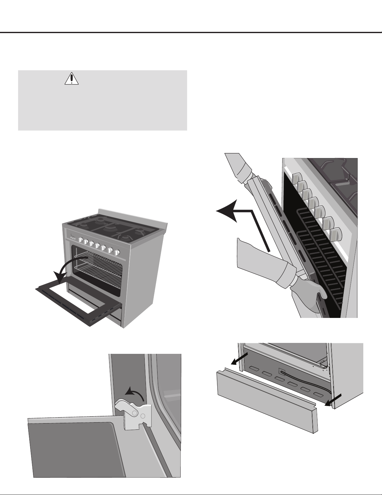
— 30 —
Maintenance
You can change the color and look of your range by
changing the oven door. For normal range use, it is not
recommended to remove the oven door. Make sure the oven
is turned off and cool when replacing the door. The oven
door is heavy, be careful when lifting it.
Follow these instructions to replace the door:
u
Open the door completely.
v
Lift up and pull the small levers located on the two
hinges all the way back to unlock.
w
While holding the door on each side, close the door
until it touches the levers. Continue closing the door
until it is about 4” (10 cm) from being completely
closed.
x
Lift up the door and pull it towards you, pulling it out
of the hinges. The door will gently detach from the
oven. If the door does not easily detach from the
oven, do not apply force and make sure the levers
are unlocked.
y
Remove the kick plate.
U
To replace the door, perform the previous steps in
reverse order.
Removing the Oven Door and Kick Plate (ranges only)
WARNINGS:
• Theremovableovendoorisheavy.Youmayneed
help removing and replacing it.
• Becarefulwhenremovingandliftingupthedoor.
• DONOTliftthedoorbythehandle,butbyholding
the door on each side.

— 31 —
Care and Cleaning
Range Top / Cooktop
• To avoid electrical shock or burns, turn off all controls
and ensure the cooktop is cool before cleaning.
• Before cleaning the cooktop, ensure that all burners are
turned off and that all components are cool enough to
safely touch.
• Do not use harsh or abrasive cleaning agents, waxes,
polishes, or commercial cooktop cleaners to clean the
cooktop. They may cause permanent damage to the
surface.
• Use only a sponge, soft cloth, brous or plastic brush,
and nylon pad for cleaning.
• Always dry components completely before using the
cooktop.
Control Knobs
To clean, use a damp soapy cloth for everyday cleaning of
the knobs. For heavier cleaning for grease, etc., apply a non-
abrasive liquid detergent to a damp cloth. Clean and then
dry completely.
Make sure not to rotate the knobs when cleaning.
Burner Grates
These three grates should only be used in their proper
positions. DO NOT operate a burner for an extended period
of time without cookware on the grate. To clean, AFTER
COOLING, use hot water or white vinegar, and DO NOT
place in a dishwasher. When replacing the grates, be sure
they are positioned securely over the burners.
Please note that the grates have rubber pads on the
feet that come into contact with the appliance to avoid
scratches. After cleaning it is important to verify that these
rubber pads are still there. Should they come off, they can
be reapplied using a heat-resistant adhesive.
Burner Rings
Lift off when cool. Wash burner rings in hot, soapy water and
rinse with clean water. To remove burned-on food particles,
you may scour with a plastic scouring pad. Thoroughly dry
before returning the rings to the appliance.
The rings are NOT dishwasher safe.
Do not use cleaners for stainless steel surfaces as these
rings are not stainless steel.
Burner Caps
Lift off when cool. Wash Burner Caps in hot, soapy water
and rinse with clean water. Remove any food from between
the burner slots using a small non-abrasive brush like a
toothbrush, and afterwards wipe using a damp cloth.
To remove deposits from the burner cavities, remove the cap
and separate the two parts. Clean the burner holes routinely
with a small gauge wire or needle and especially after bad
spillovers which could clog these holes.
Thoroughly dry before returning the heads to the appliance.
The heads are NOT dishwasher safe.
Stainless Steel
To clean the stainless steel surface, use warm sudsy water
or a stainless steel cleaner or polish. Always wipe the
surface in the direction of the grain. Follow the cleaner
instructions for cleaning the stainless steel surface.
DO NOT use a steel wool pad as it will scratch the surface.
Do not use cleaners with chlorides or chlorines. Do not use
harsh scrubbing cleaners.
Use a hot, damp cloth with a mild detergent. Use a clean,
hot, damp cloth to remove soap. Dry with a dry, clean cloth.
Metal Finishes
Wash with soap and water, glass cleaner, or mild liquid
sprays.
Plastic Finishes
When control panel trim and end caps are cool, clean with
soap and water, rinse and dry.
Use a glass cleaner and soft cloth.
WARNINGS:
• PleasemakesuretoreadALLsafetyprecautions
on pages 4 to 10 and 23 to 24.
• Electric Shock Hazard.
• Toavoidpossibleburnsusecarewhencleaning
the appliance.
- DO NOT attempt to clean the appliance
whenever the oven or burner rings are still hot.
- DO NOT attempt any of the following cleaning
instructions before turning all burners and the
oven off, and allow them to completely cool.
IMPORTANT: Always follow label instructions on
cleaning products.

— 32 —
Care and Cleaning
Ranges:
Control Panel, Door Handle, Control Housing
• Clean the control panel, door handle and control
housing with a solution of mild detergent and warm
water.
• Do not use abrasive cleaners or scrubbers; they will
permanently damage the nish.
• Dry the components with a soft, lint-free cloth.
Oven Window
• Clean all glass surfaces with a solution of mild detergent
and hot water. Use a mild glass cleaner to remove
ngerprint or smears.
• Dry completely with a soft, lint-free cloth.
Porcelain Surfaces
• Clean oven interior and inner door liners with a solution
of mild detergent and hot water.
• Rinse and dry with a soft cloth. Do not use abrasives or
commercial oven cleaners.
Oven Racks
• Clean oven racks with solution of detergent and hot
water. To clean heavy soil, use a scouring pad such as
steel wool with plenty of water.
Oven Frame
• Clean with hot water, soap-lled steel-wool pads or
cleaners. Rinse well with clean water and dry.
Oven Gasket
• Do not clean the gasket. The berglass material of the
oven door gasket cannot withstand abrasion.
• It is necessary for the gasket to remain intact.
Outer Oven Door
• Use soap and water to thoroughly clean the top, sides
and front of the oven door. Rinse well. You may also use
a glass cleaner to clean the glass on the outside of the
door.
• Do not use oven cleaners, cleansing powders of harsh
abrasives on the outside of the door.
Inner Oven Door
• Do not allow excess water to run into any holes or slots
in the door. Any soap left on the liner causes additional
stains when the oven is heated.
• Before you call for service, please review the potential
problem / possible causes and remedies shown in the
table below.
— 33 —
Troubleshooting Tips
Symptom Possible Cause Solution
No ignition spark.
Dead batteries or ignition module failed.
CAUTION
Replace batteries and attempt ignition. If there is still
no spark ignition, the appliance burners can still be
used.
To light them:
u
Holding a lit match to the ame spreader,
push in on the control knob and turn
counterclockwise to LIGHT.
v
When the ame is burning all the way round
the burner, you may adjust the heat.
Igniters spark
continuously after ame
ignition.
Power supply polarity is reversed.
Igniters are wet or dirty.
Have polarity corrected.
Dry or clean igniters.
Burners will not light.
Burner parts or igniters may be
wet, dirty or misaligned.
Check that the burner parts are clean, dry and
correctly assembled.
Check that the igniters are clean and dry.
Igniters are sparking but
burners are not igniting.
Gasshut-offvalveisinthe“OFF”
position.
Turnshut-offvalvetothe“ON”position.
Top burner will not stay
lit.
Failed thermocouple. Replace thermocouple.
The ames have
suddenly gone out.
A draft or spill has
extinguished the ame.
Turn the burners off, cleaning the burners and sump
area. Once clean, reignite top burners.
Burner ame goes out at
low setting.
Low gas pressure.
Air intake holes around burners are
obstructed.
Contact gas company.
Remove obstruction from air intake holes.
Flames do not burn all
around the burner cap.
Burner parts may be dirty or misaligned. See“CareandCleaning”instructions.
Top burners do not light
or do not burn evenly.
Plug on appliance is not completely
inserted in the electrical outlet.
Burner holes on the side of the burner
may be clogged.
Make sure the unit is properly connected to the
power supply.
Remove the burner heads and clean them. Check
the electrode area for burned-on food or grease.
Burner ames are very
large and yellow.
Burner bezel ports are clogged.
Burner ports or burner caps are not
positioned properly.
Appliance is being operated with the
wrong type of gas.
Regulator is not installed, is faulty, or is
set for the wrong type of gas.
Clean burner bezel ring ports with straightened
paperclip, needle, or wire.
Remove and carefully re-install burner bezel and
caps.
Ensure that the type of appliance matches the gas
supply.
Check installation, replace regulator, or set regulator
for proper gas.
“Cracking”or“popping”
sound is heard coming
from appliance.
This is the sound of metal heating and
cooling.
This is normal.
Nothing works.
Power supply is not energized. Have an electrician check the power supply,
including the house circuit breaker, wiring and fuses.

— 34 —
Symptom Possible Cause Solution
Oven will not heat.
Oven settings are not corrected. Adjust time, temperature, or rack position.
Foods over-cooked
or under-cooked.
Incorrect cooking time or temperature. Have polarity corrected.
Dry or clean igniters.
Troubleshooting Tips
Ranges:
— 35 —
Please register your product warranty by visiting the Ancona Home website.
Canada & USA
Phone: 1-800-350-4562
Fax: 800-350-8563
Email: [email protected]
Website: www.anconahome.com
Ancona is in association with Mr Appliance for all after sales service calls.
Please contact their service provider or visit their website:
Phone: 1-888-998-2011
Website: www.mrappliance.com
© 2022 Copyright of Ancona Home. All rights reserved. This material may not be reproduced, displayed, modied or distributed.
MAAN2160-07