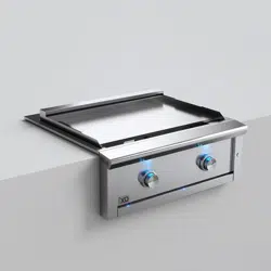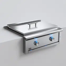

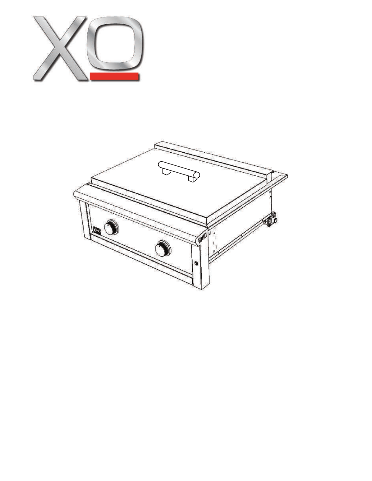
XO PRO-GRADE GRIDDLE
MODEL XOGRIDDLE30_
CONGRATULATIONS
on purchasing your XO.
Before you proceed, take just
a moment to register your XO at:
Ensuring warranty coverage should you need service
Providing ownership verification for insurance purposes
Let’s XO notify you in the event of product changes or recalls.
www.xoappliance.com/register-your-product/
REGISTRATION HELPS YOU BY -
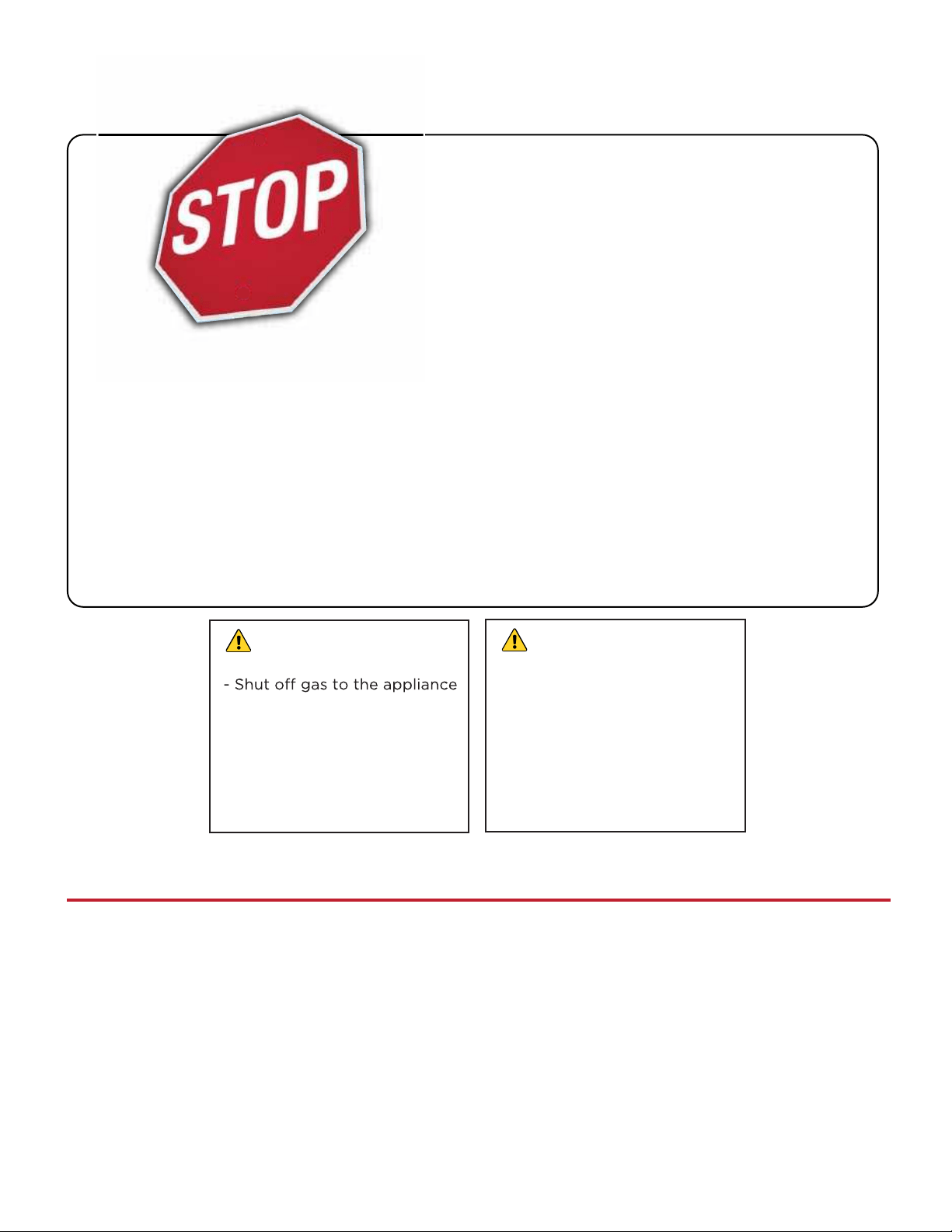
DANGER
If you smell gas:
- Extinguish any open flames
- Remove the cover
- If odor continues, maintain a
safe distance away from the
appliance and immediately
call your gas supplier
or your fire department.
WARNING
- Do NOT store or use gasoline
or other flammable liquids or
vapors in the vicinity of this
or any other appliance.
- An LP cylinder not connected
for use must NOT be stored in
the vicinity of this or any other
appliance.
FOR OUTDOOR RESIDENTIAL USE ONLY
IMPROPER INSTALLATION, ADJUSTMENT, ALTERATION, SERVICE OR MAINTENANCE CAN
CAUSE PROPERTY DAMAGE, INJURY OR DEATH. READ THIS MANUAL THOROUGHLY
BEFORE INSTALLATION, USE OR SERVICING OF THIS UNIT.
NOTE TO THE INSTALLER
This manual must remain with the unit. Check your local building codes for proper method of
installation. In the absence of local codes, this unit should be installed in accordance with the
National Fuel Gas Code No. ANSI Z21.58D-2002 USA or CAN/CGA-B149.1/.2 Natural Gas/Propane
Code. (Canada) Latest Edition or the National Electrical Code ANSI/NFPA No. 70 or the Canadian
Electrical Code CGA 1.6b2005 or the Latest Edition.
2
XOGRIDDLE30N
XOGRIDDLE30L
these are the models
covered in this
book
record your serial number
here in case you need it later
3

Before You Get Started
Installation Checklist
Specifications
Notices
General Safety
Installation
Product Dimensions
Cutout Dimensions
Location
Venting
Gas and Electrical Connections
Operating
Meet your XO
Controls
Lighting the Burners
Griddle Safety Tips
Maintenance
Care of Stainless Steel
General Cleaning
Burner Maintenance
Parts and Service
Notes and Warranty
5 - 8
9 - 22
27 - 30
31 - 33
where things are
please read and follow
all safety instructions
It’s for your
own good...
Honest.
23
- 26
4
34 - 35
installation check list
This manual must remain with the end customer.
This product is designed for outdoor, residential use only.
NEVER install this product in any enclosed space such as a garage, patio, or breezeway.
NEVER install this product into a setting constructed with combustible materials without an
XOG30JACKET insulated liner.
Observe all clearances regrding combustible and non-combustible structures and overheads
as set forth in this manual.
Ensure that the final installation is level, side to side and front to back.
Comply with all local building codes, in the absence of local codes, installation should conform
with the National Fuel Gas Code ANSI Z223.1/NFPA54, Natural Gas and Propane installation
Code, CSA B149.1 or Propane Storage and Handling Code, B149.2 in Canada.
All electrical connections must comply with local builing codes or in the absence of local codes
National Electrical Code. Appliance must be connected to a GFI protected three prong outlet.
Minimize the length of your gas run - XO recommends a minimum 3/4” ID gas supply line.
All joints and connections must be leak tested prior to first use.
All island / cabinet enclosures must include adequate cross ventilation.
NEVER install this appliance in an elevated location without the approval of local code authorities.
Ensure the area where the unit is installed is free of all combustible materials.
TEAM LIFT: This appliance is extremely heavy - two or more people are required to lift and
move it.
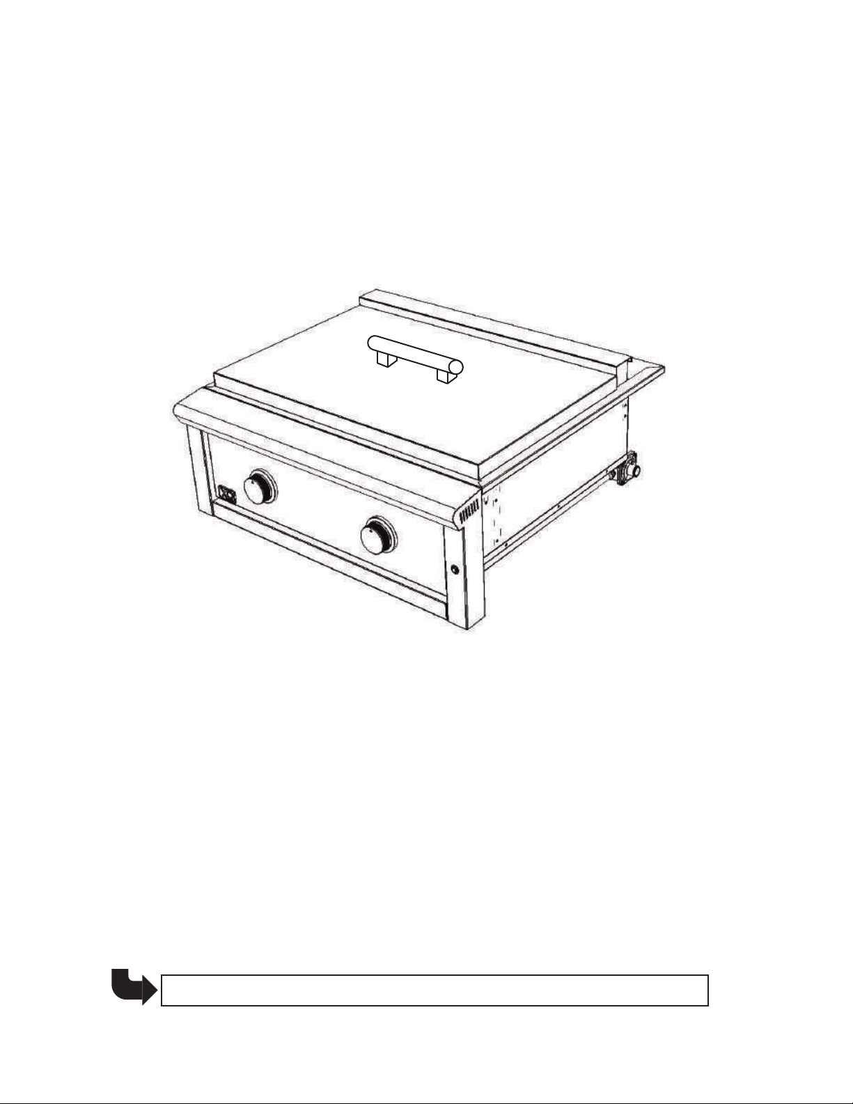
IMPORTANT: The burners are secured with cable ties to prevent movement in transit. The
Please dispose of all shipping materials in an environmentally responsible fashion.
THIS PAGE IS NOT A SUBSTITUTE FOR READING THE ENTIRE MANUAL
5

product specifications
OVERALL PRODUCT WIDTH
OVERALL PRODUCT DEPTH
OVERALL PRODUCT HEIGHT
CUTOUT WIDTH
CUTOUT DEPTH
CUTOUT HEIGHT
COOKING SURFACE WIDTH
COOKING SURFACE DEPTH
COOKING AREA TOTAL
FUEL (Specify)
NG ORIFICE SIZE
LP ORIFICE SIZE
BURNER TYPE
NUMBER OF BURNERS
BURNER CAPACITY
IGNITION SYSTEM
CONSTRUCTION
CONTROL LIGHTING
30”
28 3/4”
13 3/6”
28 3/4”
24”
10 7/8”
28”
18”
504 sq in
Natural Gas* - or - Propane
2.08 mm
1.3 mm
304 Stainless Steel “U” Tube
2
18,000 BTU each
Flame Thrower Positive Ignition
304 Welded, Polished Stainless Steel
12 VDC Blue LED (requires 115v GFI outlet)
*Recommended minimum natural gas supply piping 3/4”
please read and follow all safety instructions
6
Combustion by-product produced when using this product contain chemicals
known by the State of California to cause cancer, birth defects or other
reproductive harm.
Handling brass material on this product exposes you to lead, a chemical
known to the State of California to cause cancer, birth defects or other
reproductive harm. (Wash hands after handing this product.)
WARNING
For more information go to this website
www.P65WARNINGS.ca.gov
notice: commonwealth of massachusetts
!
Massachusetts requires all gas be installed using a plumber or gas fitter carrying
the appropriate Massachusetts license.
All permanently installed natural gas or propane installations require a “T”
handle type manual gas valve be installed in the gas supply line to this appliance.
This does not apply to portable propane installations using a 20lb cylinder.
The burning of gas cooking fuel generates some byproducts wich are on the list
of substances which are known by the State of California to cause cancer or
reproductive harm.
California law requires businesses to warn customers of potential exposure to such
substances. To minimize exposure to the substances, always operate this unit
according to the use and care instructions found in this manual. Be certain to
provide adequite ventilation while cooking.
Warning: Handling the brass material on this product exposes you to lead, a
chemical known to the State of California to cause cancer, birth defects or other
reproductive harm. (Wash hands after handling this product.)
For more information go to this website: www.p65warning.ca.gov
WARNING: CALIFORNIA PROPOSITION 65
1.
2.
3.
1.
2.
3.
4.
!
!
7
Read this manual carefully and completely before installing or using your griddle to reduce
the risk of fire, burn hazard or other injury and to ensure proper installation and servicing.
Never use rusted, dented or damaged propane cylinders. Never store additional or empty
propane cyliners in the griddle cabinet or in the vicinity of this or any other gas or electrical
appliance. Do not store propane cylinders indoors or on their sides for gas may escape.
Gas cylinders are highly flammable.
Children should NEVER be left unsupervised in an area where a griddle is located. Place your
griddle well away from areas where children play. Do not store items that may interest children
in or around the griddle, or in the cart, enclosure or island where the griddle is installed.
NEVER attempt to move the griddle while it is hot. When in use portions of the griddle are hot
enough to cause severe burns.
Always maintain the required clearances from combustible materials as detailed. The griddle
is designed for outdoor use only. Never use in a garage, building, shed, breezeway or other
enclosed area. Do NOT use th
e griddle under any unprotected overhead combustible structure.
Combustible material exposed to heat will catch fire.
Gas grills and griddles are not designed or certified for, and are not to be installed in or on any
recreational vehicles, portable trailers, boats or any other moving installation either recreational
or commercial.
Always have a fire extinguisher accessible - NEVER attempt to extinguish a grease fire with
water or other liquids.
Store your griddle in a well ventilated are. If stored indoors, detach and store propane cylinders
separately outdoors in a secure, well- ventilated area away from heat where children cannot
tamper with them. Always store propane tanks outdoors.
Keep all electrical cords and fuel supply lines away from heated surfaces. Electrical cords and
hoses should be placed away from walkways to avoid tripping hazards.
All repairs and service should be completed by a certified and qualified technician experienced
in gas BBQ appliance repair.
smell gas, check for leaks immediately using a soap and water solution only. NEVER check
for gas leaks with an open flame.
Inspect the LP supply hose prior to each use of the griddle. If there is evidence of abrasion,
wear, cuts or cracks it must be replaced prior to using the appliance.
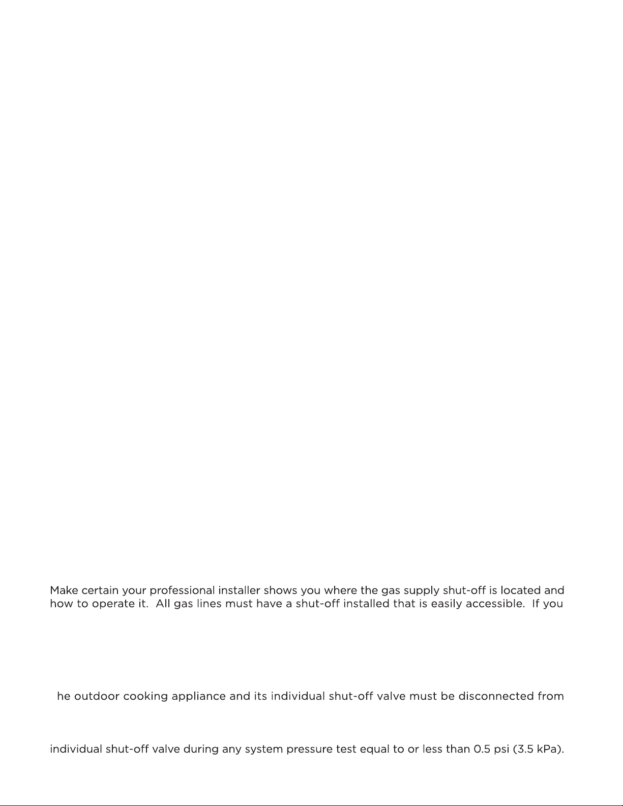
T
the gas supply piping during any system pressure test in excess of 0.5 psi (3.5 kPa).
The outdoor cooking appliance must be isolated from the gas supply piping by closing its
.
.
.
.
.
.
.
.
.
.
.
.
.
.
your safety matters
8
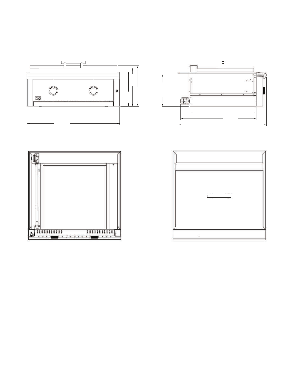
product dimensions
please read and follow all safety instructions
12-3/8”
315mm
13-3/16”
335mm
11-11/16”
282mm
28-3/4”
730mm
24-5/8”
625mm
30”
760mm
FRONT
BOTTOM
SIDE
XOGRIDDLE30
TOP
21-1/2”
546mm
10-1/2”
267mm
9
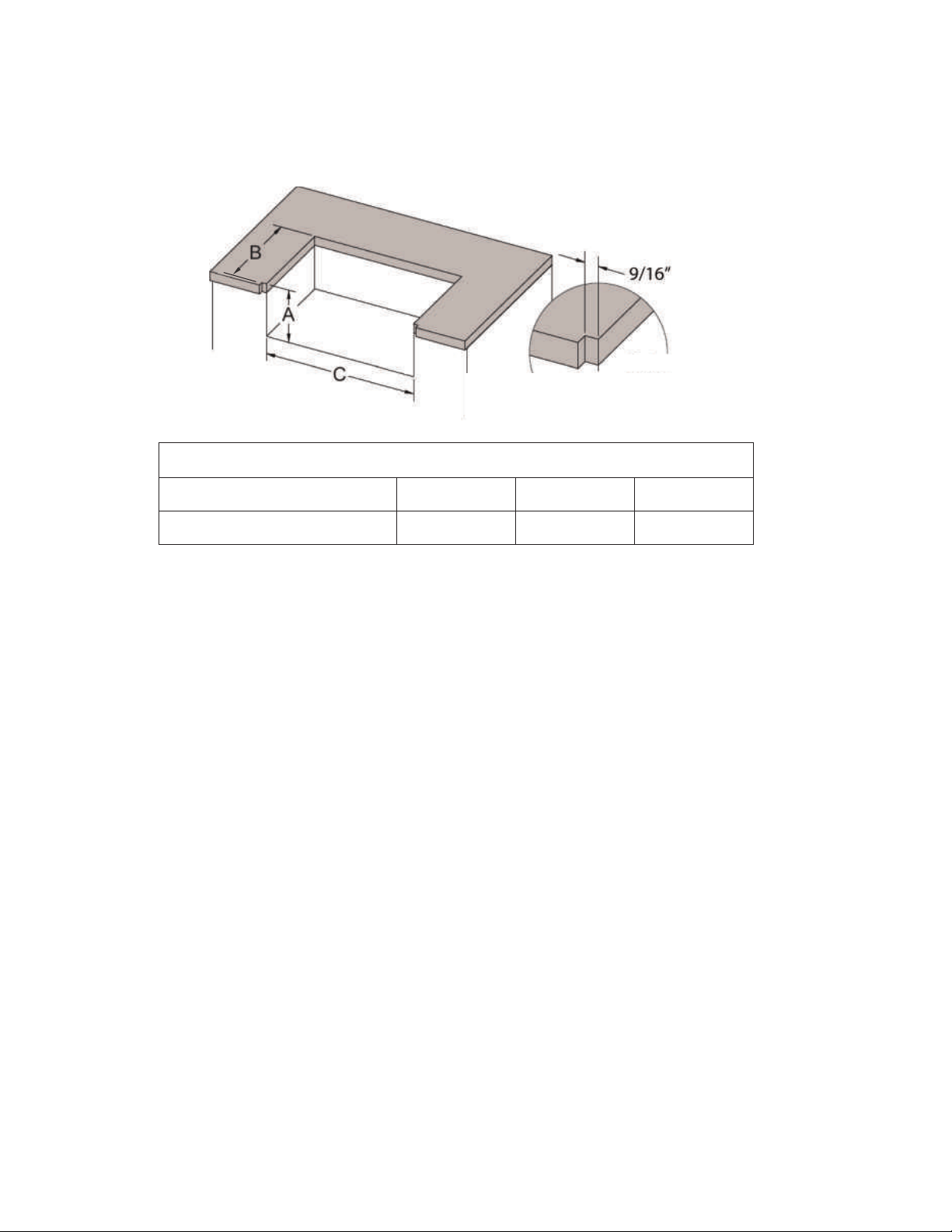
XOGRIDDLE30 10 7/8” 24” 28 3/4”
A
B
C
Overhung Countertop
Notch Cutout Detail
XOG30JACKET 12” 25 3/4” 31 1/4”
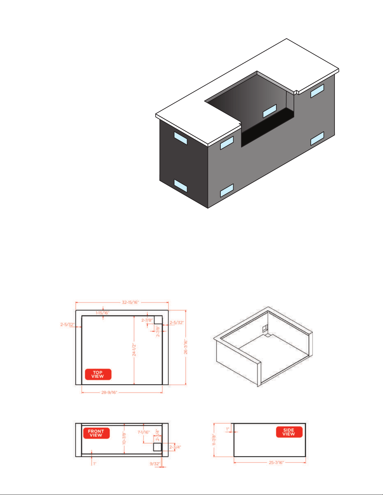
cutout dimensions
INSTALLATION IN A COUNTERTOP
NON-COMBUSTIBLE CONSTRUCTION
When installing your XO griddle in a location built using non-combustible materials such as
masonry - use the smaller dimension cutouts: 10 7/8” H x 24” D x 28 3/4” W
COMBUSTIBLE CONSTRUCTION
When installing your XO griddle in a location built using combustible materials such as wood
or vinyl - you must install the XOG30JACKET liner first -
use the larger cutout dimensions:
12” H x 25 3/4” D x 31 1/4” W
THE NOTCH
IMPORTANT NOTE: The depth shown is measured from the vertical face of the counter.
When the coutertop overhangs the counter, you must notch both corners of the cutout as
shown above. The width of the notch is 9/16” - the depth of the notch is equal to the depth
of the overhang. If the coun
tertop overhans by 1”, the notch should be 1” deep back to the
vertical face of the counter.
The notch allows the bullnose of the griddle to be recessed for a finished look.
10
THE LOCATION OF YOUR OUTDOOR COOKING APPLIANCES CAN
DRAMATICALLY AFFECT THEIR PERFORMANCE
NEVER install this product into a setting built from combustible materials without an
insulated jacket (XO Part number - XOG30JACKET) to isolate the griddle from the
structure. Doing so could result in fire, property damage and / or personal injury.
Combustible material is anything which can ignite, burn, melt or emit smoke.
NEVER locate the griddle under an unprotected overhead combustible structure.
NEVER locate the griddle in an enclosed space such as a building, garage, shed,
breezeway or similar location.
Check your local building codes for proper method of installation. In the absence of
local codes, this unit should be installed in accordance with the National Fuel Gas
Code ANSI Z223.1/NFPA54, Natural gas and Propane installation code, CSA B149.1,
or Propane Storage and Handling Code, B149.2, in Canada.
MINIMIZE YOUR GAS RUN
Keep all gas supply lines as short and straight as possible. Piping long distances, changes in
direction and reduced pipe diameters all contribute to press drop and reduced performance
of your outdoor cooking appliances. XO Recommends a minimum 3/4” ID gas supply line.
ON THE LEVEL
During installation, using a carpenter’s spirit or electronic level make certain you griddle is
level both side to side and front to back.
WARNING
.
.
.
.
.
griddle location
team lift
Two or more people are required to handle the griddle plate
WARNING
NEVER install this appliance in an elevated location without the approval of local code authorities.
ALWAYS maintain a safe clearance area around all outdoor cooking appliances keeping them
free of all combustible materials such as fabrics, wall treatments, decorative items and sources
of ignition such as articles containing fuel or those with an open flame, heating coils or pilot
light.
11
NON-COMBUSTIBLE CONSTRUCTION
Your XO griddle is designed easy placement in a non-combustible structure such as an island
or similar outdoor structure built of masonry or Hardibacker.
In such an installation, the griddle has a perimeter flange that rests on the countertop allowing
the unit to simply slide into place in the prepared cutout. No additional fastening is required.
Do not grout the unit in place. This allows easy removal for future service or maintenance.
In such installations where the surrounding materials used are non-combustible, a minimum
clearance of 12” must be maintained on either side and 5” behind the griddle.
WHEN COMBUSTIBLE CONSTRUCTION MATERIALS ARE PRESENT
Combustible materials are defined here as anything which will ignite, melt, emit smoke and/or
fumes or be deformed by heat.
If combustible construction materials are present in the vicinity of the griddle such as wooden
framing, vinyl or wooden siding, etc . -
a minimum clearance of 18” must be maintained in all
directions from
the griddle AND the unit must be installed using an XOG30JACKET insulated
liner. The cutout dimensions are increased to accommodate the liner which is placed without
fastening into the cutout. The liner is supported by a perimeter flange which rests upon the
countertop and the griddle rests upon that flange.
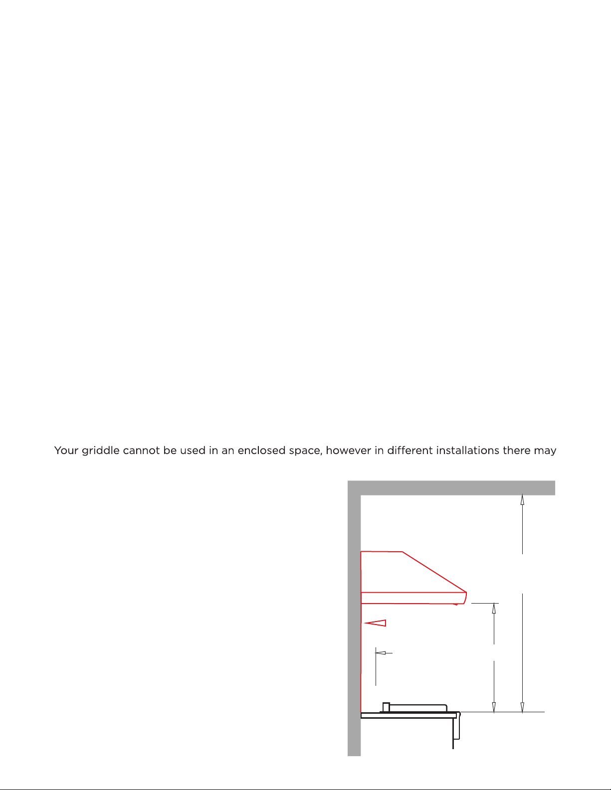
OVERHEAD CLEARANCE
also be overhan
Minimum overhead clearance (above cooking surface)
60” to Non-Combustible overhead.
Hood must extend a minimum of 3” on all sides of
the cooking area.
Hood must have a flow rate of 1000 CFM minimum.
Hood must be connected to a dedicated GFI
protected circuit.
All other minimum clearances must be observed.
Combustible Overhead Construction Must Be
Protected By An Approved Hood.
Use Of An Approved Hood Is Highly Recommended
With Non-Combustible Overhead Construction.
ging or overarching structures which must be taken into account.
griddle location (continued)
12
5”
min.
30” to 36”
60”
minimum above
cooking surface to
non-combustible overhead
We recommend oversizing the hood by 3" on
each side to maximize efficiency and capture
space
For example;
A 30" Griddle would require a 36" Hood
NON-COMBUSTIBLE
BACKSPLASH
REAR WALL
OVERHEAD CONSTRUCTION
Non-Combustible Construction
Sides 12” Back 5”
Combustible Construction
Sides 18” Back 18”
FRESH AIR IN
HOT AIR VENT
griddle location (continued)
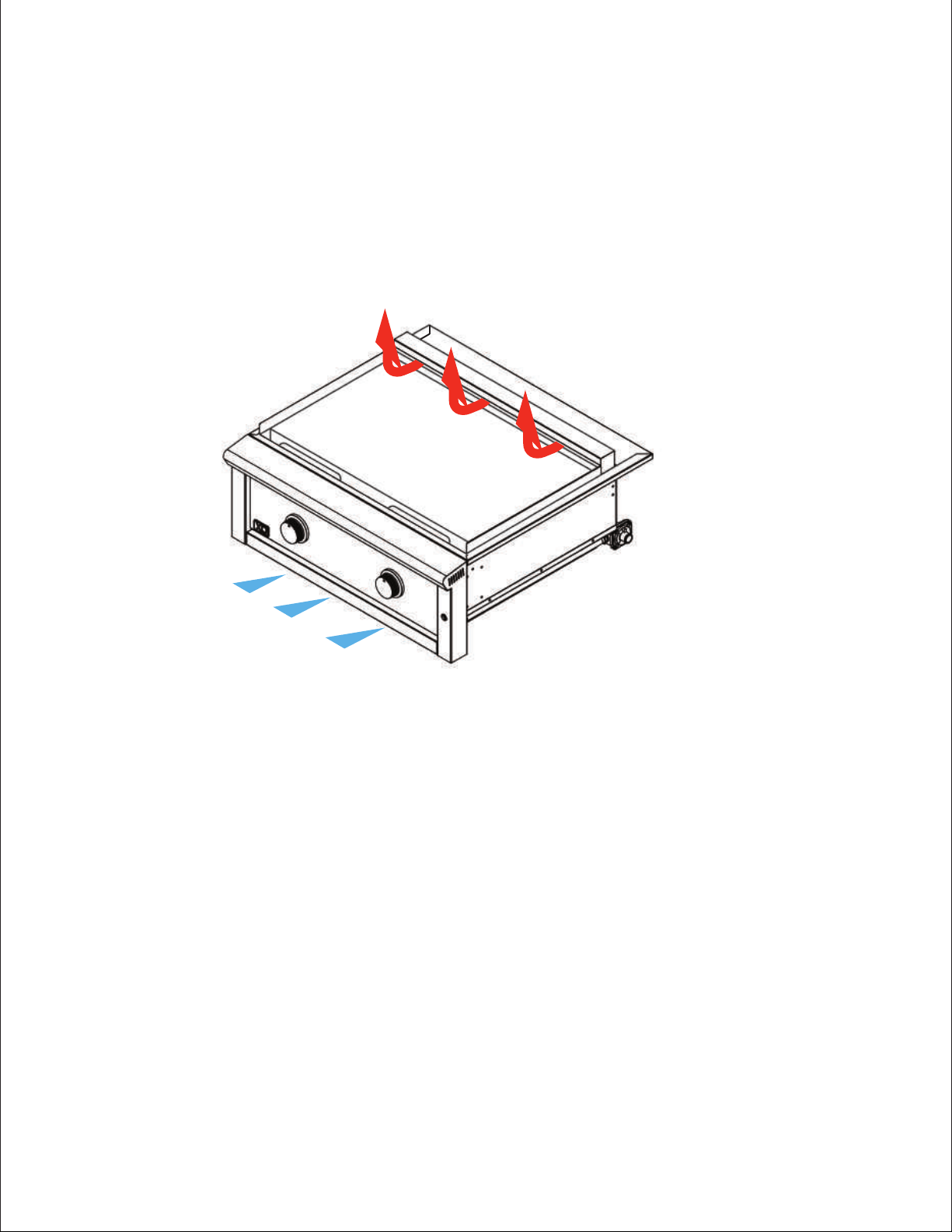
WIND | COMBUSTION AIR | HEAT
Your XO griddle is a high performance cooking machine. As such it requires plenty of air to
support combustion at the burners.
Air flow is designed to enter at the front around the control panel and super-heated air is
exhausted through the long horizontal vent at the back of the griddle.
Because the burners are covered by the griddle plate the design of the appliance makes it
less susceptable to wind patterns than a grill, however care should be taken to avoid conflicts
with strong prevailing wind patterns.
In the case where strong prevailing winds might interfere with the
safe and comfortable
operation of the griddle, a wind break is strongly advised. Failure to do so may result in an
excessive build up of heat internally which could cause heating of the control knobs, damage
to the LED power lead, igniter wires or discoloration of the control panel.
It is important to remember that your griddle can generate much more heat than an indoor
kitchen range.
13
venting your island
Proper venting is required for all island
or counter construction to prevent the
accidental formation of pockets of
flammable gas. This requirement
applies to both Natural Gas and
Propane installations.
There should be at least 2 vents
per side, one mounted near the
top of the counter, the second
must be installed a minimum of
2 1/4” above ground level.
Each vent must have a minimum
of 10 sq in of open area. Placing
vents on opposite sides ensures
cross ventilation.
Safe operation requires adequate
air flow - make certain there are no
unventilated voids.
IMPORTANT NOTE
In planning your island kitchen build - make certain you have a solid foundation capable of
supporting the combined weight of the appliances, frame, countertop and other building
materials.
LOCATION OF THE UTILITIES
The gas connection and electrical hook up are located at the rear, right hand side of the unit.
(see drawing of the XOG30JACKET below so see location)
14
WARNING
NEVER CONNECT A GAS LINE DIRECTLY TO THE GRILL. A PRESSURE REGULATOR MUST
BE INSTALLED ON ALL GAS EQUIPMENT. ALL LOCAL CODES REQUIRE IT AND XO SUPPLIES
THE CORRECT REGULATOR WITH YOUR UNIT. REMOVING OR FAILING TO INSTALL THE
PRESSURE REGULATOR CAN RESULT IN FIRE AND SERIOUS PERSONAL INJURY AND WILL
VOID THE WARRANTY
critical that the gas you use matches that which the grill was set up for. You can verify that
by checking the rating
plate. The Rating Plate lists serial numbers, model numbers and gas
type.
Ensure that the gas supplied meets with the minimum pressure requirements. Do not operate
the grill on any gas other than that for which the grill has been set.
Water Column Requirements
Both the regulator and manifold
orifices have been tuned for the
type gas identified on the rating
plate.
factory original parts from XO. All installation and all installation parts must conform to local
codes with the National Electrical Code, ANSI Z223.1/NFPA 70 latest edition and the National
Fuel Gas Code, ANSI Z223.1/NFPA54 in the U.S. and CGA-B149.1/.2 in Canada.
XO recommends that only qualified professionals perform the required plumbing, installation
and maintenance on this product.
To ensure satisfactory performance, the gas supply line must be sized to accommodate the
total BTU requirements of all the gas-fired equipment that will be connected to that line. In
no case should an inlet pipe less than 3/4” ID or 1” OD ever be used to connect this product.
Calculate the total BTU output of all equipment and refer to “Gas Supply Line Runs” for
allowable run distances for 3/4” pipe. Failure to meet these minimum requirements may
reduce performance of the grill and any other appliances running on that supply line. Always
keep supply line runs as short as possible. (See: “BTU Output” for specific model outputs)
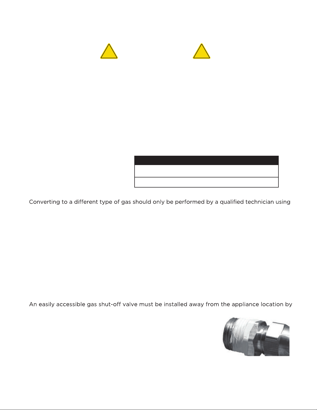
a qualified plumber.
Keep the first two pipe threads free of any sealing compound
to prevent pieces breaking loose which could clog a burner valve.
Do not use sealing compound on flare fittings.
For built-in installations it is recommended that flexible pipe used
be kept as short as possible.
FUEL
N G
L P
WC MAX INLET
10 in
14 in
WC MIN INLET*
4 in
11 in
*under full load
gas connections
!
!
15
XO cooking appliances are factory set to use either propane (LP) or natural gas (NAT). It is
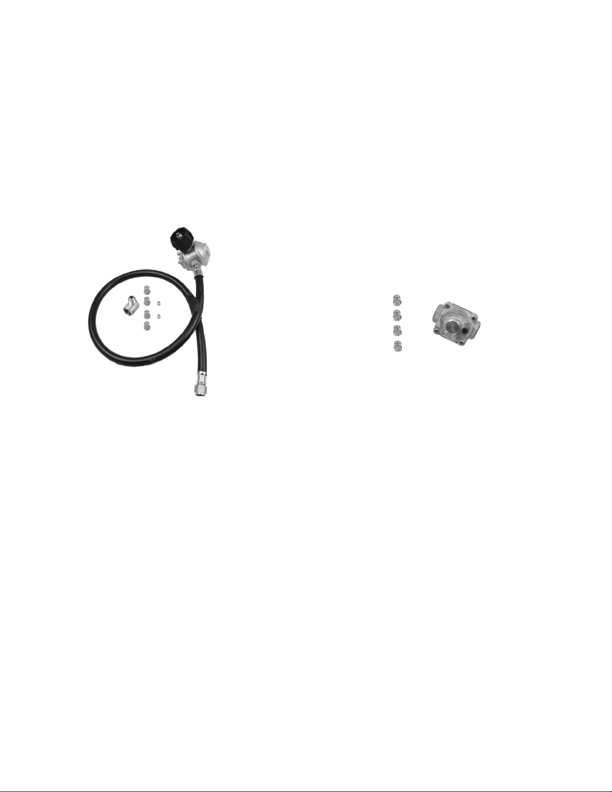
NATURAL GAS CONNECTION KIT INCLUDED
Grills and griddles models for Natural Gas come with the correct orifices, air shutter settings,
regulator and elbow necessary to attach the unit to your gas supply.
The gas griddle manifold ends in a 1/2” male thread and Grip Nut for a wrench.
Connect the brass elbow to the end of the manifold - using a wrench on the manifold to
prevent it from turning while tightening the elbow.
Use plumbers putty or gas tape to seal the threads leaving the first two threads free of
sealant. This is to prevent loose material from accidently getting trapped in the line where
it could clog the valves.
Connect the regulator - note the direction of gas flow is marked. If installed backwards it
will not work.
Attach your Flexline from the house gas supply.
Leak test all connections.
WARNING
Regulators set for Natural Gas and LP (Liquid Propane) are NOT interchangable.
Use ONLY the regulator supplied with your XO.
NEVER connect to an unregulated gas supply.
Always use a professional to connect to your natural gas supply.
Always turn valve OFF when not in use.
Failure to follow the above information exactly may cause fire, explosion, serious
injury or death.
using natural gas
!
!
HOW TO LEAK TEST
Make a soapy water solution: 1 part liquid dish soap to 3 parts water
Make certain all control knobs are in the OFF position
Using a brush or spray, apply the soapy mixture to all connections.
Check for bubbles which indicate a leak.
NEVER test for a gas leak using an open flame.
16
Gas
Supply
Inside
Wall
Outside
Wall
Shut-Off
Male
Fitting
To griddle
Regulator
Quick Disconnect
When Using 12ft. Hose
Locking
Shut-Off
Flex-Line Or
12" Hose
griddle
Regulator
Swivel
Nut
12ft. Hose
XOLQD
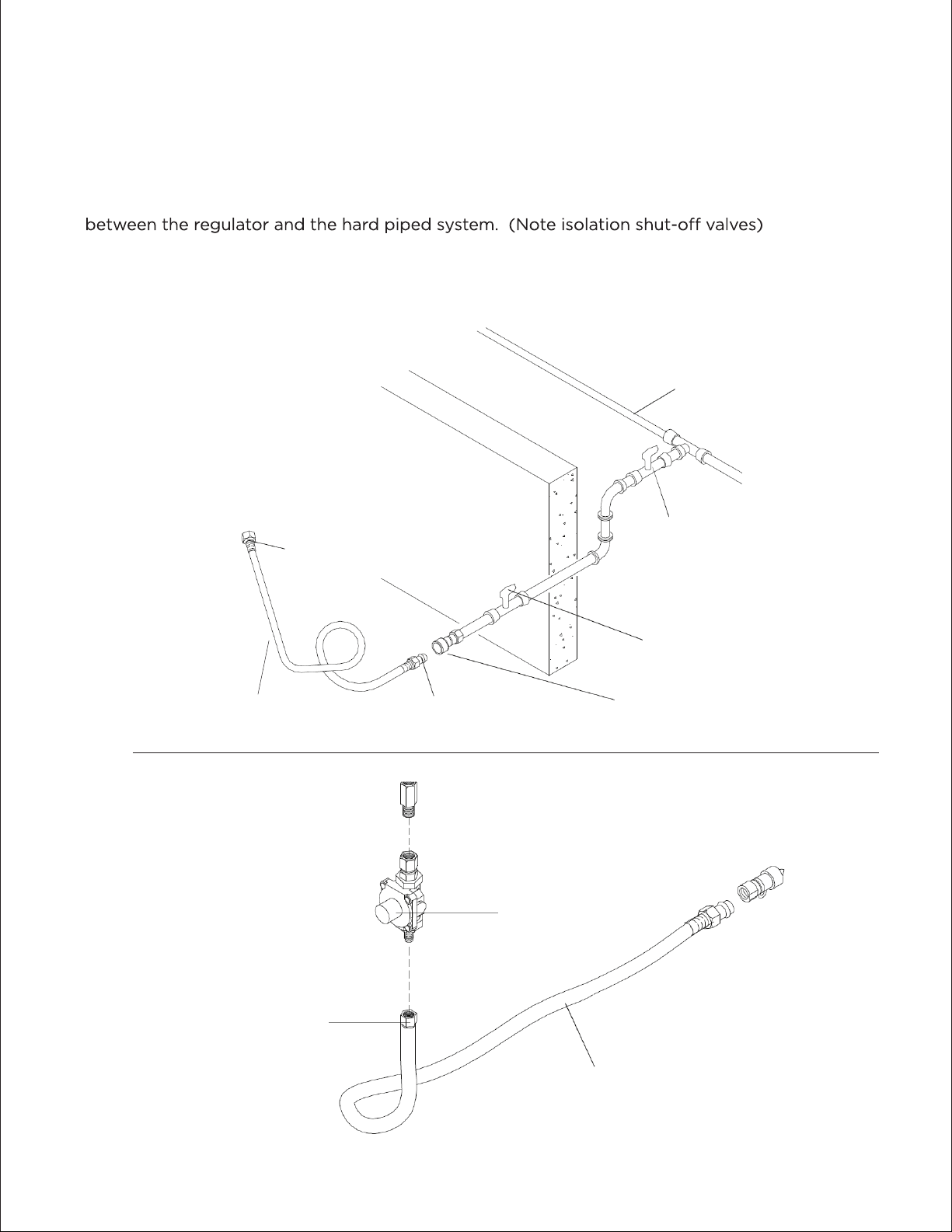
connecting to a permanently plumbed gas line
Follow the example diagrams below to connect your griddle to a permanently plumbed system.
For Natural Gas, use of a Stainless Steel Flexline is recommended to make the final connection
For a hard piped LP (propane) system attaching to a portable cart, a 12’ XOLQD detachable
supply hose is recommended. (The XOLQD cannot be used with Natural Gas).
17

LP (Liquid Propane) GAS
Grills and griddles set up for LP gas come equipped with an LP hose/regulator assembly
for connection to a standard 20 lb. LP cylinder. (Type 1). All fittings necessary to attach the
assembly to the grill are included.
Permanently plumbed LP connections, such as those in line with a bulk cylinder, require a
4/11 regulator.
LP CYLINDER REQUIREMENTS
The LP cylinder must be constructed and marked in accordance with the specifications for
LP gas cylinders of the U.S. Department of Transportation (DOT) and designed for use with a
Type 1 system only.
Cylinders of free standing grills must be secured using the provided cylinder retention system
to avoid accidental movement.
2016 cylinder with an
over-fill protection device.
Never use a cylinder with a damaged valve.
Always check for leaks after every LP cylinder change. (See: “Leak Test” for further details.).
Cylinders must be stored outdoors in a well-ventilated area out of the reach of children.
If your grill is stored indoors, the LP cylinder must be stored outside.
WARNING
Regulators set for Natural Gas and LP (Liquid Propane) are NOT interchangable.
Use ONLY the regulator/hose assembly supplied with your XO.
Always turn valve OFF when not in use.
Do not store a spare LP-gas cylinder under or near this appliance.
NEVER fill the LP cylinder beyond 80% of capacity.
Tanks can release vapor if heated when not in use.
Failure to follow the above information exactly may cause fire, explosion, serious
injury or death.
using an lp (propane) gas cylinder
!
!
18
When exchanging your cylinder for a refill, exhange only for a Type 1
Connect and tighten the swivel nut of the gas hose to the griddle manifold connection
located at the right, rear of the unit. The connection must angle down, away from
the griddle to keep the gas line away from the heat generated during use.
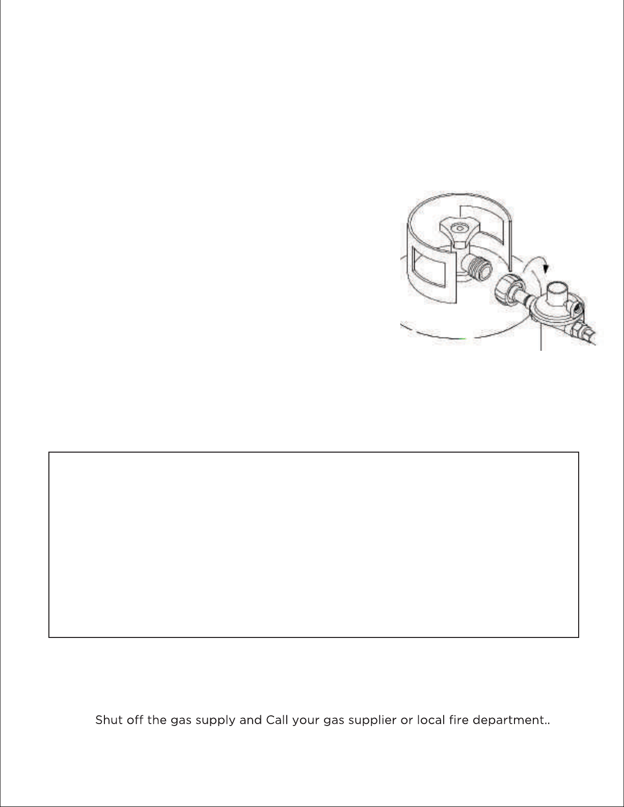
CONNECTING THE TANK TO THE REGULATOR
Turn all control knobs to the OFF position.
Inspect the valve connection port, regulator and hose
for damage or debris.
Remove any debris - NEVER use damaged equipment.
Connect the regulator assembly to the tank valve and
hand tighten the nut clockwise to a full stop.
DO NOT over tighten or use wrenches. It can damage
the quick Coupling and cause a leak and/or fire hazard.
Open the tank valve slowly a full turn (counter-clockwise)
and use a soapy water solution to check for leaks before
attempting to light the griddle.
If a leak is found, close the tank valve and do not use your griddle until the leak is
repaired.
HOW TO LEAK TEST
Make a soapy water solution: 1 part liquid dish soap to 3 parts water
Make certain all control knobs are in the OFF position
Using a brush or spray, apply the soapy mixture to all connections.
Check for bubbles which indicate a leak.
NEVER test for a gas leak using an open flame.
PRIOR TO THE FIRST USE AND EVERYTIME YOU CHANGE YOUR LP TANK YOU
MUST CHECK FOR LEAKS.
gas connections - lp (propane)
WARNING
NEVER connect any outdoor appliance to an unregulated gas supply.
NEVER attempt to use any outdoor appliance if you smell gas
19
Page 22
fuel type conversion
All units ship set up at the factory for either Natural Gas or Propane.
They can be converted if required, however this conversion should only be undertaken by a
qualified technician experienced in gas appliance repair and service.
All the necessary components for the conversion can be found in kit form along with specific
instructions to complete the conversion.
LP CONVERSION KIT NG CONVERSION KIT
XOGLPKIT XOGNGKIT
20
Product installation must meet local electric codes or, in the absence of local codes, the
latest edition of the National Electrical Code ANSI/NFPA No. 70 or the Canadian Electrical
Code CGA 1.662005.
Use only a Ground Fault Interrupter (GFI) protected circuit with this outdoor cooking appliance.
This
griddle is equipped with a three prong (grounding) electric plug for your protection against
shock hazard and must be plugged directly into a properly grounded three prong outlet.
Never cut or remove the grounding prong from this plug.
Use only extension cords with a 3 prong grounding plug, rated for the power of the
equipment, and approved for outdoor use with a “W-A” marking.
To protect against electric shock, keep all wiring dry, do not immerse any part of the
power cord, an extension cord or any plugs in water or other liquid.
Unplug the product from the outlet when not in use and before cleaning. Ensure that
all equipment has cooled completely before performing any cleaning or maintenance.
Do not let any wiring touch heated surfaces.
Place all power cords to avoid trip hazards and secure excess loops.
Do not use an outdoor cooking gas appliance for purposes other than intended.
Do not operate any outdoor cooking gas appliance with a damaged cord or plug.
Do not attempt to operate any appliance that malfunctions or has been damaged in
any manner. Contact the dealer for repair.
electrical hook up and safety
WARNING
CALIFORNIA PROPOSITION 65
The electrical supply cord and plug of the
transformer contain chemicals including
lead, known to the State of California to
cause cancer, and birth defects or other
reproductive harm. Wash hands after handling
!
!
WARNING - ELECTRICAL GROUNDING
!
!
21
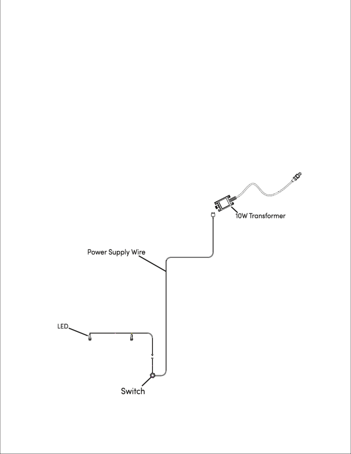
Griddle burner ignition does not require electricity, however the control LED light do.
Your griddle control lighting is powered by a 12VDC transformer which must be plugged into
a properly grounded GFI protected outlet. If you are uncertain if an existing outlet meets this
requirement, consult a licensed electrician.
NEVER remove or circumvent the third grounding prong.
The transformer and its attendant wiring must be secured to the cart or interior of the island
to avoid loose electrical cables. Make certain that all electrical wiring is positioned such that
it cannot contact hot surfaces.
electrical wiring
22
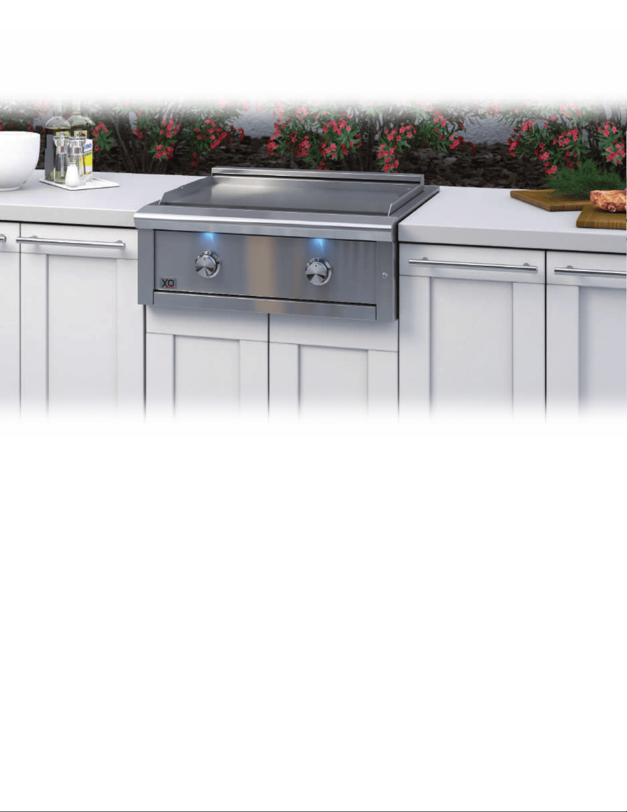
meet your xo
Get ready for a unique grilling experience with your new XO Griddle, packed with
features that will enhance your outdoor kitchen and expand your culinary boundaries.
PRO-GRADE 304 Stainless Steel Welded Construction
Massive, Solid 304 Stainless Steel Cooking Surface
Twin 18,000 BTU Stainless Steel “U” Shaped Burners
for rapid, even heating
Reliable Flame Thrower Ignition
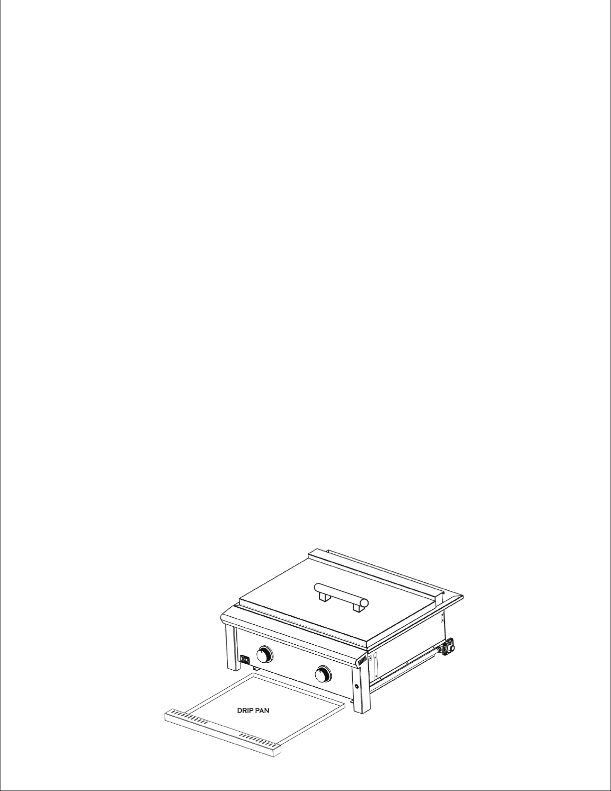
Built-In Grease Trough
Full Width Removable Drip Pan For Easy Cleaning
23
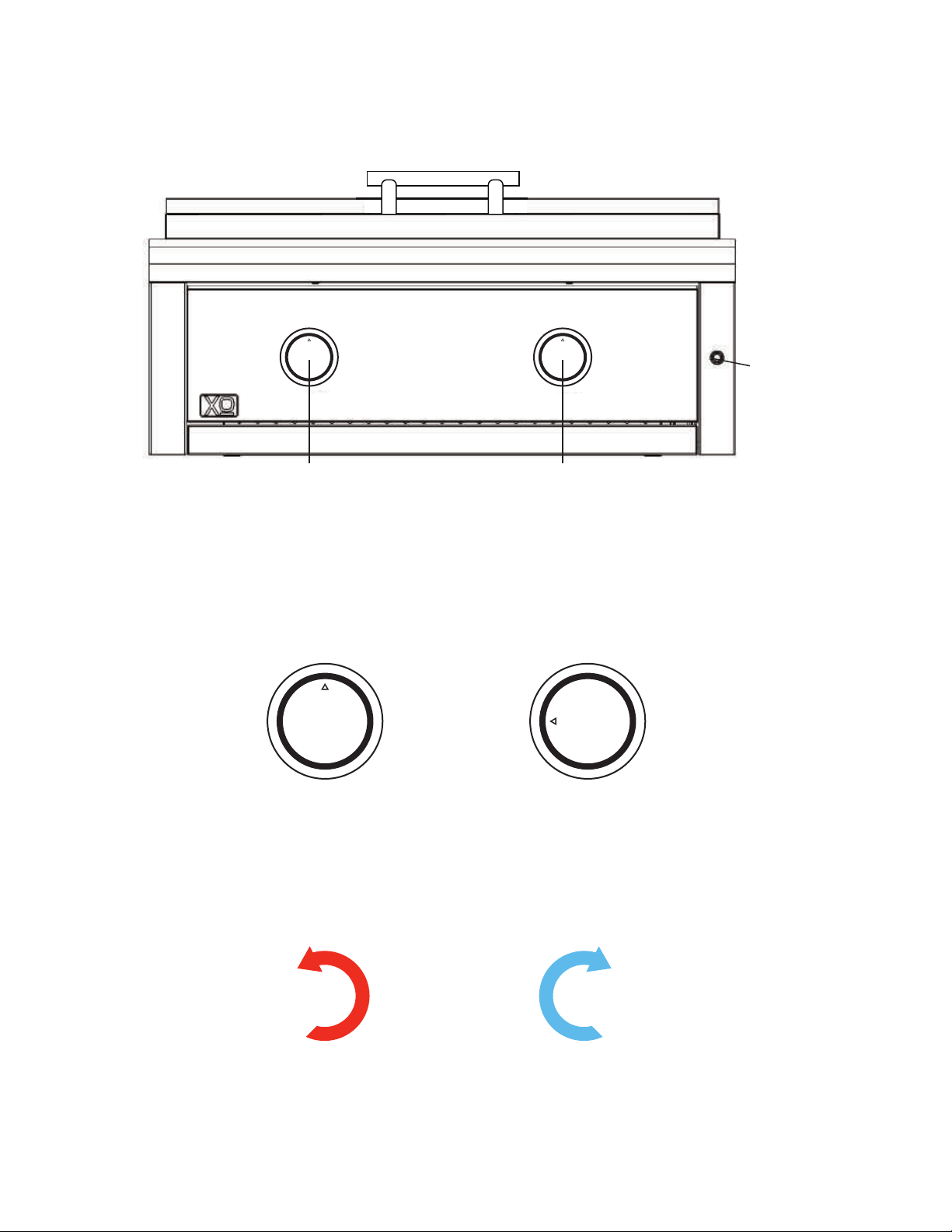
controls
ignition
please read and follow all safety instructions
LEFT
BURNER
CONTROL
RIGHT
BURNER
CONTROL
LED
LIGHTS
ON/OFF
BUTTON
OFF POSITION LIGHTING/HIGH
POSITION
OFF
LOW
HI
OFF
LOW
HI
24
KNOBS TURN ON COUNTER CLOCK WISE AND SHUT OFF CLOCKWISE.
ON OFF
NEVER leave the griddle unattended,
Before the first use - you MUST lift the griddle plate and ensure that all tie downs have been
removed from the burners. These are just to prevent shifting during shipping.
Avoid loose fitting clothing while operating your griddle.
NEVER touch the griddle or surrounding surfaces during operation as these will become
extremely hot and can result in severe burns.
Use insulated gloves or mitts operatin or handling anything hot.
NEVER operate the griddle with the cover in place.
NEVER lean over or reach across a hot griddle.
NEVER heat unopened
food containers - pressure build up can cause them to burst.
NEVER line your griddle with aluminum foil, this can alter the flow of air internally and result
in damage to the unit. Such damages are excluded from your warranty.
Cooking excessively fatty or similar foods can cause flare-ups. Damages resulting from flare-
ups or fires resulting from the unit operating unattended are not covered under the warranty.
NEVER operate the griddle without the drip pan in place.
Grease i
s extremely flammable. The grease pan and trough must be cleaned after each use.
Let hot grease cool completely before cleaning and proper disposal. Failure to clean and
de-grease the unit can attract pests and create a broad range of health and safety issues
including fire and explosion.
NEVER operate any gas fired outdoor appliance that has not been leak tested.
NEVER operate any gas fired outdoor appliance while under the influence of drugs or alcohol.
important griddle safety tips
25
OFF POSITION LIGHTING/HIGH
POSITION
OFF
LOW
HI
OFF
LOW
HI
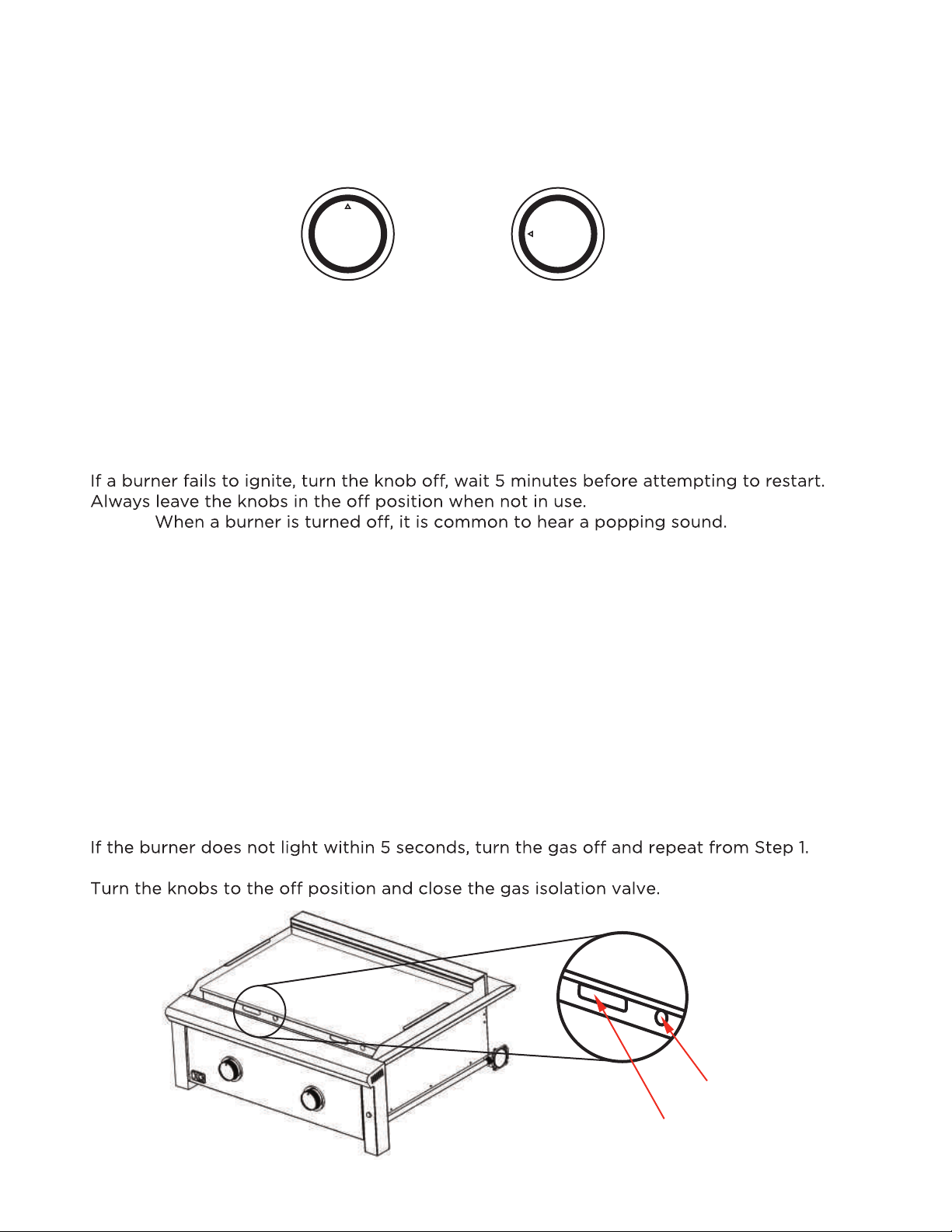
lighting the burners
LIGHTING WITH FLAME THROWER IGNITION
To light a burner, remove the lid and open the gas isolation or tank valve.
Push and hold the control knob in - this will start the flow of gas. Wait 3 to 5 seconds.
While holding the knob in, turn the knob to the left to the 9 o’clock position
An audible click will sound and the burner will ignite.
The flame will be visible through the port next to the flash tube.
To light the second burner, slowly open that control knob.
NOTE:
PREHEAT YOUR GRIDDLE FOR BEST RESUTS.
Prior to lighting - using a cooking oil that will not smoke, oil the griddle surface to prepare it.
Before cooking turn both burners on medium until your desired temperature is reached. The
extra thick griddle plate holds the heat. If it gets too hot, you will have to wait for it to cool.
MANUALLY LIGHTING THE GRIDDLE.
NEVER attempt to re-light a burner without waiting 5 minutes for any residual gas to dissipate.
At arms length, using a long stem match or long reach lighter next to a flash tube in the grease
trough (see diagram below). There is one for each burner.
Slowly rotate the knob for that burner 1/4 turn to the left to the HI position.
If the burner will not light after several attempts - Call for service -
Observe Flame Here
Light Here
26
Here are a few tips to avoid this:
CARE OF STAINLESS STEEL
XO outdoor kitchen products are precision crafted from high quality 304 Stainless Steel but
to keep keep it looking and working its best, here are best practices for cleaning Stainless,
• After each use, wipe d
own the exterior of the griddle to remove grease and splatters.
• Be sure to follow the cleaning instructions in this manual.
• Use a commercially available Stainless Steel cleaner* to clean and polish exterior surfaces.
In order to preserve the fine grain finish - when removing stubborn stains:
• Do not use abrasive cleaners and always rub in the direction of the grain.
• Some household cleaners are not suitable for stainless steel; always check the label before
using.
• Always use the mildest cleaning solution first, scrubbing in the direction of the grain.
Grease can get stuck in the grain of the stainless steel and bake on giving the appearance of
rust. To remove these baked-on stains use a fine to medium non-metallic abrasive pad with a
stainless steel cleaner.
DRIP TRAY - The drip tray should be cleaned after every use
Extreme care must be taken to protect all Stainless components if solutions are used for
cleaning concrete and masonry which can be very corrosive and will attack stainless steel.
LOCATIONS NEAR POOLS AND COASTAL AREAS:
The 304 stainless steel material used in the construction of is highly rust resistant, however,
chlorine in the air from swimming pools or the salt from sea air may cause surface rust to
appear and even create some pitting if left on the product.
maintenance
• For seasonal storage use the product referred to above, ensure the grill is dry, then cover
securely to minimize the amount of damp air getting to the surfaces.
YOUR XO WARRANTY DOES NOT COVER OCCASIONAL SURFACE RUST OR STAINING DUE
TO ENVIRONMENTAL CONDITIONS.
XO Outdoor cooking products are high performance units and generate high heat.
*RATED FOR HIGH HEAT
27
• Regularly wipe down the exterior surfaces with a damp cloth.
• Allow the surfaces to dry before covering. Do not cover a damp grill.
CLEANING THE GRIDDLE
Regular cleaning and care for your Xo Griddle will keep it looking and functioning its best.
The cook surface is designed to hold a fine layer of cooking oil creating a ‘seasoning’ on its
surface. This seasoning promotes a non-stick cooking surface and is easily maintained. Caring
for XO’s cook surface is much like maintaining cast iron cookware. When the surface requires
cleaning, there are a few basic cleaning techniques to use. For quick and routine cleaning
between preparations, a metal spatula or scraper works for removing the majority of surface
debris. For tougher areas or where sugars glaze the cook surface, pour a small amount of
warm water on the soiled surface while the grill is warm and scrape the debris away with a
spatula. Heat the cook surface to a high temperature and allow the sticky debris to become
brittle. Once the debris is brittle, use the spatula or scraper to remove it. The juice of fresh
lemons can also be used to clean and condition the surface. Afterwards, wipe the cooking
surface with vegetable oil again before using.
To reduce the chance of fire, the grease trough should be visually inspected before each use.
Remove any grease and wash with a mild soap and warm water solution.
ROUTINE CLEANING OF THE GRIDDLE INTERIOR
at least every 6 months you must give the entire griddle a thorough cleaning to minimize your
risk of fire and keep your griddle in top shape.
FOLLOW THESE STEPS.
Turn
all control knobs to the full OFF position. Turn the LP tank valve to the full OFF position
or turn the Natural Gas supply OFF.
Remove the griddle top and clean thoroughly. (WARNING: Handle with two people)
Remove and clean the burners (see procedure that follows)
Check orifices for any obstructions and check igniters.
Scape out and brush the interior and bottom of the griddle with a scraper, fiber pad or nylon
brush. Wash wih a mild soap and warm water solution. Rinse thoroughly and let dry.
Replace burners making certain they are centered correctly on their respective orifices..
Replace griddle top. (WARNING: Handle with two people)
IMPORTANT NOTE: Keep the area around all outdoor kitchen appliances clear and free of
all combustible or corrosive m
aterials. This includes fuels, flammable liquids and vapors as
well as pool chemicals. Make certain all ventilation openings in the appliances, carts and/or
island enclosures are clear and free of debris.
maintenance
28
BEFORE THE FIRST USE
Before the first use wash the griddle top with a mild soap and warm water solution using a
wash cloth or soft vegetable brush to scrub away any residue.
WARNING: Before attempting any burner maintenance ensure the gas supply is OFF and all
control knobs are in the OFF position. Make certain the griddle has completely cooled before
proceeding.
TO REMOVE THE BURNERS
Remove the griddle top (
All burner tie downs to prevent shifting during shipping must be removed if they have not been
already.
Tilt the far end of the burner up (at rear of griddle) and lift the burner up and away from the
orifice. at the front of the burner. Be careful not to disturb the air shuttle p osition.
CLEANING THE BURNERS
To maximize your burner performance, clean the exterior of the burner with a wire brush, Clear
stubborn scale with a scraper.
Clear any clogged gas ports with a straightened paper clip - do not use a wooden or plastic
toothpick
Shake out any debris through the venturi and air shutter.
Inspect the venturi / air shuttle to make certain it is clear. If any obstructions can be seen, use a
WARNING: TEAM LIFT, this requires two people)
WHEN YOUR GRIDDLE ARRIVES - THE BURNERS ARE SECURED IN PLACE BY CABLE TIES
TO PREVENT DAMAGE IN SHIPPING. THESE MUST BE REMOVED PRIOOR TO INITIAL USE.
WARNING
maintenance - burners
VENTURI SECTION
PORTS
29
straightened wire coat hanger and or bottle brush to clean them out.
WARNING: WHEN REPLACING THE BURNERS, THE VENTURI SECTION MUST BE CENTERED
AROUND THE ORIFICE. FAILURE TO LOCATE ON THE ORIFICE CAN RESULT IN FIRE, PROPERTY
DAMAGE, INJURY OR DEATH.
AIR ADJUSTMENT
Burners are tested and pre-set at the factory for the type of fuel indicated on the model label.
burner’s operation.
In addition, if the unit is converted to burn a fuel other than what was originally set at the facory
the air shuttle position will have to be adjusted. This should only be done by a trained qualified
professional experienced in grill repair and maintenance.
! !
Spiders and small insects can spin webs and nest in the griddle burner venturis
which can obstruct gas flow, causing it to ignite outside the burner tube. This type
of “FLASHBACK FIRE” can cause serious damage to the griddle and create a
dangerous operating condition.
To reduce the chance of FLASHBACK FIRE you must inspect and clean the venturis at least
twice a year in summer and fall or whenever spiders are active in your area, or if the the
griddle has not been used for an extended period.
After removing the griddle plate (CAUTION: this part is extremely heavy and will require at
least two people to handle safely), carefully remove the burners by tilting the burner up and
away from the gas valve orifice.
The venturi section of the burner is the part closest to the brass orifice.
Using a bottle brush or bent wire
coat hanger - carefully clean the
venturi section of the burner to
ensure it is free of debris.
IMPORTANT: When replacing the burners care must be taken to ensure the burner venturi is
re-centered over the orifice. Failure to do so will result in poor burner performance and will
cause ignition problems. If you are unsure how to perform this critcal maintenance - call for
service.
maintenance
WARNING
30

how to obtain parts
Parts not under warranty can be ordered directly on our website www.xoappliance.com.
Parts under warranty can be obtained by contacting our service department through our
website or by call 973-403-8900.
You will need the following information found on the Model Name Plate, located on the drip
tray of your unit. To save time, take a moment and record it here:
Appliance Model Number ______________________________
Appliance Serial Number _______________________________
Type of Gas (Propane or Natural )________________________
For warranty purposes you will need to have proof of puchase.
To assist you, a parts diagram is included in this manual.
Part Number ___________ Part Description __________________________
Part Number ___________ Part Description __________________________
Part Number ___________ Part Description __________________________
Part Number ___________ Part Description __________________________
Part Number ___________ Part Description __________________________
31
parts
32
service & maintenance record
DATE OF INSTALLATION:
DATE OF SERVICE:
WORK PERFORMED:
DATE OF SERVICE:
WORK PERFORMED:
DATE OF SERVICE:
WORK PERFORMED:
DATE OF SERVICE:
WORK PERFORMED:
DATE OF SERVICE:
WORK PERFORMED:
DATE OF SERVICE:
WORK PERFORMED:
DATE OF SERVICE:
WORK PERFORMED:
DATE OF SERVICE:
WORK PERFORMED:
DATE OF SERVICE:
WORK PERFORMED:
DATE OF SERVICE:
WORK PERFORMED:
33

notes
34
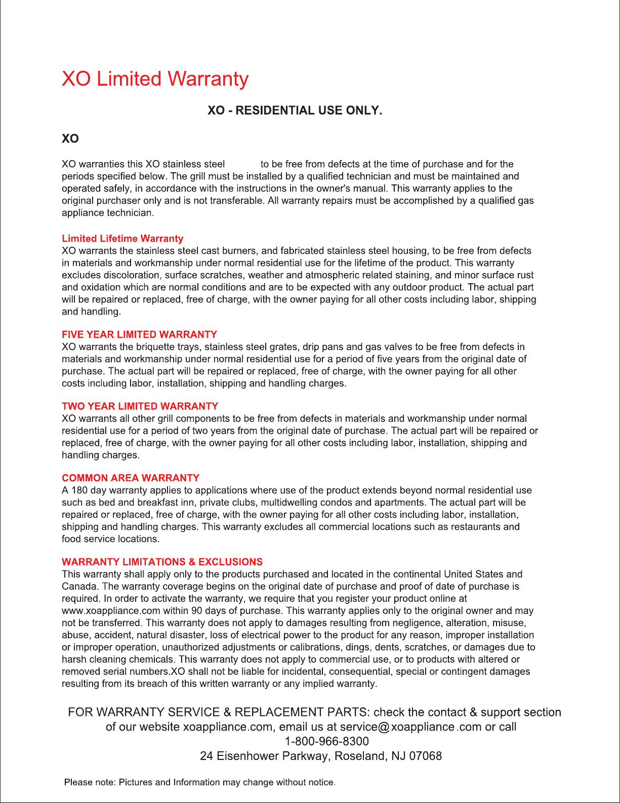
WARRANTY TERMS FOR
Stainless Steel Outdoor Cooking Appliances
griddle
we’ve got your back
now you’re cooking
973-403-8900
OR VISIT US ONLINE
WWW.XOAPPLIANCE.COM