
SEARS
OWNER'S
MANUAL
MODEL NO.
944.601880
Caution:
Read and follow
all Safety Rules
and Instructions
Before Operating
Th,s Equipment
(RRFTSMRWJ
20.0 HP
ELECTRIC START
42" MOWER
AUTOMATIC
LAWN TRACTOR
•Assembly
•Operation
•Customer Responsibilities
•Service and Adjustments
•Repair Parts
Sears Canada, Inc., Toronto, Ontario M5B 2B8
SAFETY RULES
Z_ Z_
Safe Operation Practices for Ride-On Mowers 41_
IMPORTANT: THIS CUTTING MACHINE IS CAPABLE OF AMPUTATING HANDS AND FEET ANO THROWING OBJECTS.
FAILURE TO OBSERVE THE FOLLOWING SAFETY INSTRUCTIONS COULD RESULT IN SERIOUS INJURY OR DEATH.
I. GENERALOPERATION
• Read, understand, and follow all instructions in the
manual and on the machine before starting.
•Only allow responsible adults, who are familiar withthe
instructions, tooperate the machine.
•Clear the area ofobjects such as recks, toys, wire, etc.,
which could be picked up and thrown by the blade.
•Be surethe areais clearof otherpeople before mowing.
Stop machine ifanyone enters the area.
•Never carry passengers.
•Do not mow in reverse unless absolutely necessary.
Always lookdown and behindbeforeand whilebacking.
•Be aware ofthe mower discharge direction and do not
point itat anyone. Do not operate the mower without
either the entire grass catcher or the guard in place.
•Slowdown beforetuming.
•Neverleavearunningmachineunattended. Alwaystum
offblades, set parkingbrake, stop engine, and remove
keys before dismounting.
•Turn offblades when not mowing.
•Stop engine before removing grass catcher or unclog-
ging chute.
•Mow only in daylight or good artificiallight.
•Do notoperate themachine while under theinfluenceof
alcohol or drugs.
• Watch fortrafficwhen operating near or crossing read-
ways.
•Use extra care when loading or unloading the machine
intoa trailer or truck.
•Data indicates thatoperators, age 60 years and above,
are involved in a large percentage of riding mower-
related injuries. These operators should evaluate their
ability to operate the riding mower safely enough to
protect themselves and others from serious injury.
n. SLOPE OPERATION
Slopesare a rnaor factorrelatedto loss-of-controland tipover
accidents,whichcanresult insevereinjuryor death. Allslopes
requireextracaution.Ifyoucannotbackuptheslopeorifyoufeel
uneasyon it, do notmow it.
DO:
•Mow up and down slopes, not across.
•Remove obstacles such as recks, tree limbs, etc.
•Watch for holes, ruts, or bumps. Uneven terrain could
overturn the machine. Tafl grass can hide obstacles.
•Use slowspeed. Choose a lowgear sothat you willnot
have to stop or shift while on the slope.
•Followthe manufacturer's recommendations for wheel
weights or counterweights to improve stability.
•Use extra care with grass catchers or other attach-
ments. These can change the stability ofthe machine.
•Keepall movementontheslopesslowandgradual. Do not
make suddenchangesin speed or direction.
Avoidstartingor stoppingon a slope. Iftireslose traction,
disengagethebladesand proceedslowlystraightdownthe
slope.
DO NOT:
•Do not turnon slopes unlessnecessary, and then, turn
slowlyand gradually downhill, ifpossible.
• Do not mow near drop-offs, ditches, orembankments.
: The mower couldsuddenlytum over ifawheelis over the
edge of a cliff or ditch, or ifan edge caves in.
•Donotmowonwetgrass.Reducedtractioncouldcause
sliding.
•Do not tryto stabilize the machine by puttingyour foot
onthe ground.
•Do not use grass catcher on steep slopes.
III. CHILDREN
Tragic accidents can occur ifthe operator isnot alert tothe
presence of children. Children are often attracted to the
machine and the mowing activity. Never assume that
children will remain where you last saw them.
•Keep children out of the mowing area and under the
watchful care of another responsible adult.
•Be alert and turn machine offifchildren enter the area.
•Before and when backing, look behind and down for
small children.
•Nevercarrychildren. Theymayfalloffandbeseriously
injured or interfere with safe machine operation.
•Never allowchildren to operate the machine.
•Usa extrscarewhen approaching blindcomers, shrubs,
trees, or other objectsthat may obscure vision.
IV. SERVICE
•Use extra care in handling gasoline and other fuels.
They are flammable and vapors are explosive.
-Use onlyan approved container.
-Never remove gas cap or add fuel with the engine
running. Allowengine tocoolbefore refueling. Do not
smoke.
-Never refuel the machine indoors.
-Never storethemachine orfuelcontainerinsidewhere
there is an open flame, such as a water heater.
•Never run a machine inside a closed area.
•Keep nutsand bolts,especially bladeattachment bolts,
tightand keep equipment in good condition.
•Never tamper with safety devices. Check their proper
operation regularly.
•Keep machine free of grass, leaves, or other dabds
build-up,Clean oilorfuel spillage.Allowmachine tocoot
before storing.
•Stop and inspectthe equipment ifyou strike an object.
Repair, ifnecessary, before restarting.
•Never make adjustments or repairs with the engine
running.
•Grass catcher components are subject to wear, dam-
age, and deterioration,whichcouldexpose moving parts
orallowobjects tobe threwn. Frequently checkcompo-
nents and replace with manufacturer's recommended
parts, when necessary.
•Mower bladesare sharpand cancut. Wrap theblade(s)
or wear gloves, and use extra caution when servicing
them.
•Check brake operation frequently. Adjust and service
as required.
2
SAFETY RULES
& Safe Operation Practices for Ride-On Mowers &
Be sure the area isclear ofother people before mowing. Stop
machine if anyone enters the area.
Never carry passengers or children even with the blades off.
Do not mow in reverse unless absolutely necessary. Always
look down and behind before and while backing.
Never carry children. They may fall off and be seriously
injured or interfere with safe machine operation.
Keep children out ofthe mowing area and under the watchful
care of another responsible adult.
Be alert and tum machine off if children enter the area.
Before and when backing, look behind and down for small
children.
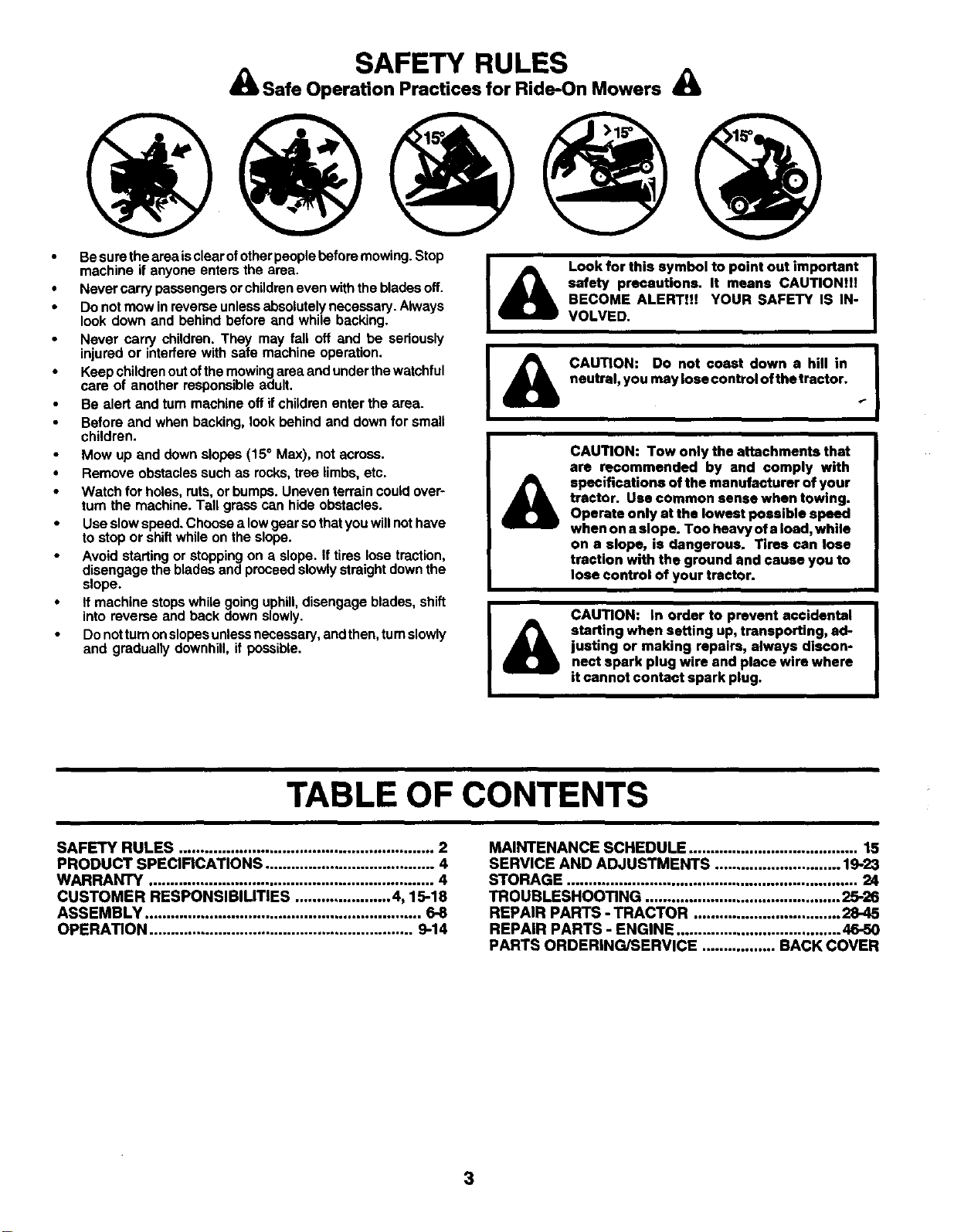
Mow up and down slopes (15° Max), not across.
Remove obstacles such as rocks, tree limbs, etc.
Watch for holes, ruts, or bumps. Uneven terrain could over-
turn the machine. Tall grass can hide obstacles.
Use slow speed. Choose alow gear so thatyou will nothave
to stop or shift while on the slope.
Avoid starting or stopping on aslope. If tires lose traction,
disengage the blades and proceed slowly straight down the
slope.
If machine stops while going uphill, disengage blades, shift
into reverse and back down slowly.
Donot turn onslopes unless necessary, and then, turn slowly
and gradually downhill, if possible.
&
Look for this symbol to point out important
safety precautions. It means CAUTION]!!
BECOME ALERT!!! YOUR SAFETY IS IN-
VOLVED.
CAUTION: Do not coast down a hill in
neutral, you may lose control of the tractor.
CAUTION: Tow only the attachments that
are recommended by and comply with
specifications of the manufacturer of your
tractor. Use common sense when towing.
Operate only at the lowest possible speed
when on a slope. Too heavy of a load, while
on a slope, is dangerous. TIres can lose
traction with the ground and cause you to
lose control of your tractor.
CAUTION: in order to prevent accidental
starting when setting up, transporting, ad-
justing or making repairs, always discon-
nect spark plug wire and place wire where
it cannot contact spark plug.
TABLE OF CONTENTS
SAFETY RULES ........................................................... 2
PRODUCT SPECIFICATIONS ....................................... 4
WARRANTY .................................................................. 4
CUSTOMER RESPONSIBILITIES ...................... 4, 15-18
ASSEMBLY ................................................................ 6-8
OPERATION ............................................................. 9-14
MAINTENANCE SCHEDULE ....................................... 15
SERVICE AND ADJUSTMENTS ............................. 19-23
STORAGE ................................................................... 24
TROUBLESHOOTING ............................................. 25-26
REPAIR PARTS - TRACTOR .................................. 28-45
REPAIR PARTS -ENGINE ...................................... 46-50
PARTS ORDERING/SERVICE ................. BACK COVER
3
PRODUCT SPECIFICATIONS
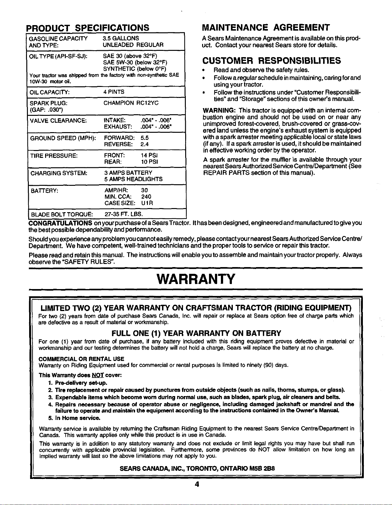
GASOLINE CAPACITY 3.5 GALLONS
AND TYPE: UNLEADED REGULAR
OIL TYPE (API-SF-SJ): SAE 30 (above 32°F)
SAE 5W-30 (below 32°F)
SYNTHETIC (below 0°F)
Your tractorwas shippedfrornthe factorywith non-syntheticSAE
=10W-30 motoro .
OIL CAPACITY: 4 PINTS
SPARK PLUG: CHAMPION RC12YC
(GAP: .030")
VALVE CLEARANCE: INTAKE: .004" - .006"
EXHAUST: .004" - .006"
GROUND SPEED (MPH): FORWARD: 5.5
REVERSE: 2.4
TIRE PRESSURE: FRONT: 14 PSI
REAR: 10 PSI
CHARGING SYSTEM: 3 AMPS BATTERY
5AMPS HEADLIGHTS
BATTERY: AMP/HR: 30
MIN. CCA: 240
CASE SIZE: UIR
BLADE BOLT TORQUE: 27-35 FT. LBS.
I
MAINTENANCE AGREEMENT
A Sears Maintenance Agreement isavailable on this pred-
uct. Contact your nearest Sears store for details.
CUSTOMER RESPONSIBILITIES
• Read and observe the safety rules.
•Follow a regular schedule in maintaining, cadng for and
using your tractor.
• Follow the instructions under "Customer Responsibili-
ties" and "Storage" sections of this owner's manual.
WARNING: This tractor isequipped with an internal com-
bustion engine and should not be used on or near any
unimproved forest-covered, brush-covered or grass-cov-
ered land unless the engine's exhaust system isequipped
with a spark arrester meeting applicable local or state laws
(ifany). If a spark arrester isused, it shouldbe maintained
in effective workingorder bythe operator.
A spark arrester for the muffler is available through your
nearest Sears Authorized Service Centre/Department (See
REPAIR PARTS section of this manual),
CONGRATULATIONS onyourpurchase ofa Sears Tractor. Ithas been designed, engineered and manufactured togiveyou
the best possibledependability and performance.
Shouldyou experience any problem you cannoteasily remedy, please contact yournearest Sears Authorized Service Centre/
Department. We have competent, well-trained technicians and the proper tools to service or repair this tractor.
Please read and retainthis manual. The instructionswillenable you toassemble and maintain yourtractor properly. Always
observe the =SAFETY RULES".
WARRANTY
LIMITED TWO (2) YEAR WARRANTY ON CRAFTSMAN TRACTOR (RIDING EQUIPMENT)
For two (2) years from date of purchase Sears Canada, Inc. will repair or replace at Sears option free of charge pads which
are defective as a result of matedal or workmanship.
FULL ONE (1) YEAR WARRANTY ON BATTERY
For one (1) year from date of purchase, if any battery included with this dding equipment proves defective in material or
workmanship and our testing determines the battery will not hold a charge, Sears will replace the battery at no charge.
COMMERCIAL OR RENTAL USE
Warranty on Riding Equipment used for commercial or rental purposes is limited to ninety (90) days.
This Warranty does _cover:
1. Pre-delivery set-up.
2. Tire replacement or repair caused by punctures from outside objects (such as nails, thoms, stumps, or glass).
3. Expendable items which become worn during normal use, such as blades, spark plug, air cleaners and belts.
4. Repairs necessary because of operator abuse or negligence, including damaged jackshaft or mandrel and the
failure to operate and maintain the equipment according to the instructions contained in the Owner's Manual.
5. In Home service.
Warranty service is available by returning the Craftsman Riding Equipment to the nearest Sears Service Centre/Depadment in
Canada. This warranty applies only while this product is in use in Canada.
This warranty is in addition to any statutory warranty and does not exclude or limit legal rights you may have but shall run
concurrently with applicable provincial legislation. Furthermore, some provinces do NOT allow limitation on how long an
implied warranty will last so the above limitations may not apply to you.
SEARS CANADA, INC., TORONTO, ONTARIO M5B 2B8
4
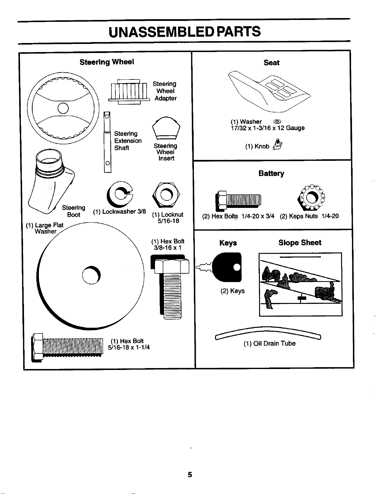
UNASSEMBLED PARTS
Steering Wheel
Steering
Wheel
,_, Adapter
tSteedng O
Extension
Shaft Steering
Wheel
Insert
Seat
(1) Washer
17/32 x1-3/16 x 12 Gauge
(1) Knob
Baffery
Boot (1) Lockwasher 3/8 (1) Locknut (2) Hex Bolts 1/4-20 x 3/4
5/16-18
(1) Large Flat
Washer
(1) Hex Bolt Keys
3/8-16 x 1
(1) Hex Bolt
5/16-18 x 1-1/4
(2) Keps Nuts 1/4-20
Slope Sheet
(2) Keys
(1) Oil Drain Tube
5
ASSEMBLY
Your newtractor has been assembled at thefactory withexception ofthose parts left unassembled forshippingpurposes. To
ensure safe and proper operation ofyourtractor all parts and hardware you assemble must be tightened securely. Use the
correct tools as necessary to insure proper tightness.
TOOLS REQUIRED FOR ASSEMBLY
A socket wrench set will make assembly easier. Standard
wrench sizes are listed.
(1) 9/16" wrench Pliers
(2) 7/16" wrenches Tire pressure gauge
(2) 1/2" wrenches Utility knife
When rightor lefthand ismentioned inthismanual, itmeans
when you are in the operating position (seated behind the
steering wheel).
TO REMOVE TRACTOR FROM CARTON
UNPACK CARTON
• Remove all accessible loose parts and parts cartons
from carton.
•Cut, from top to bottom, along lines on all four comers
of carton, and lay panels flat.
•Check for any additional loose parts or cartons and
remove.
BEFORE REMOVING TRACTOR FROM
SKID
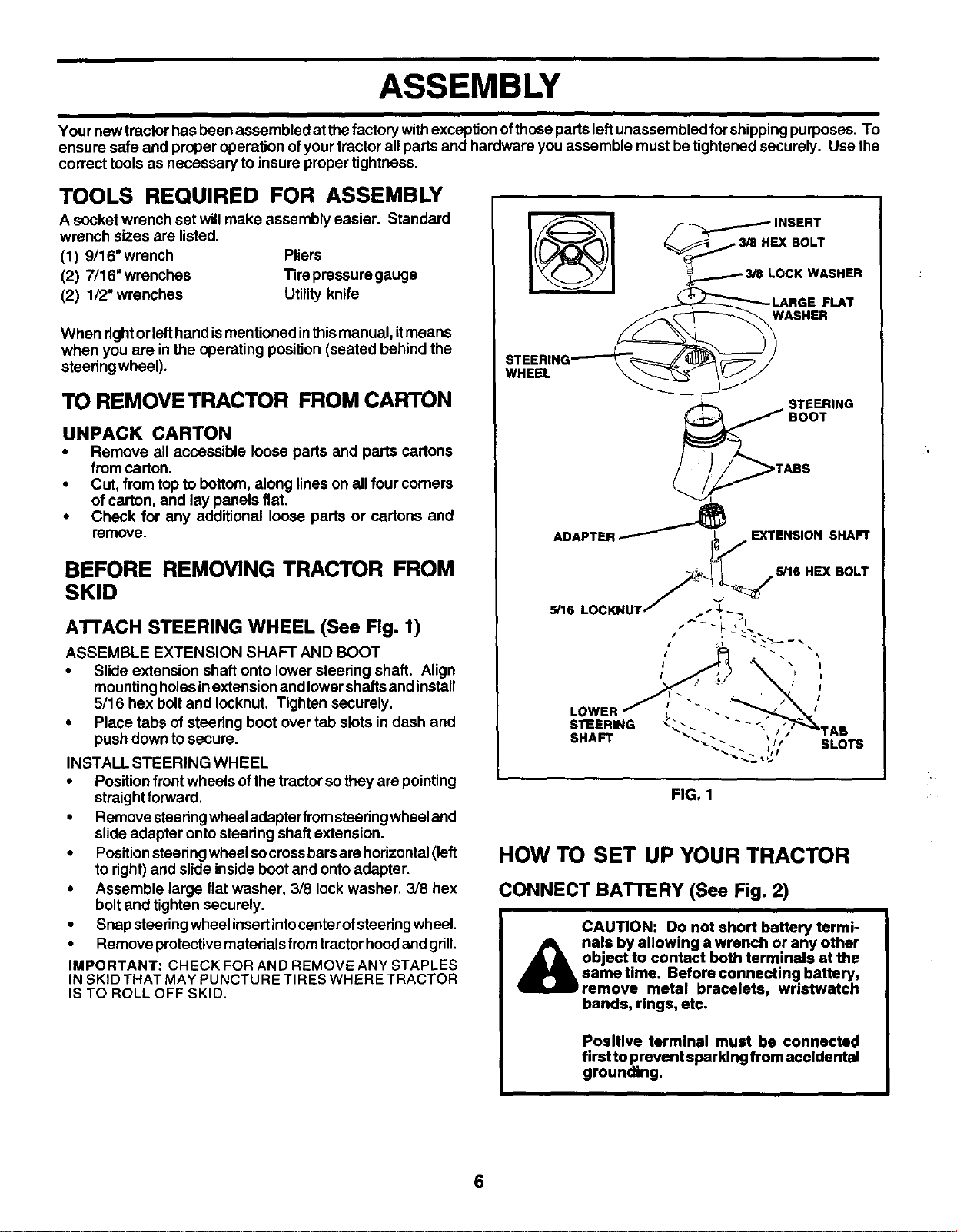
ATrACH STEERING WHEEL (See Fig. 1)
ASSEMBLE EXTENSION SHAFT AND BOOT
•Slide extension shaft onto lower steering shaft. Align
mountingholesinextension and Iowershafts and install
5/16 hex boltand Iocknut. Tighten securely.
•Place tabs of steering boot over tab slots in dash and
push down to secure.
INSTALLSTEERING WHEEL
•Position frontwheels ofthe tractorsothey are pointing
straightforward.
•Remove steeringwheel adapterfromsteeringwheel and
slide adapter onto steering shaft extension.
•Positionsteedng wheel socrossbars are horizontal(left
to right)and slide inside bootand onto adapter.
•Assemble large flat washer, 3/8 lock washer, 3/8 hex
boltand tighten securely.
• Snap steeringwheel insertintocenter ofsteeringwheel.
•Remove protectivernaterialsfromtractorhood and grill.
IMPORTANT: CHECK FOR AND REMOVE ANY STAPLES
IN SKIDTHAT MAY PUNCTU RE TIRES WHERE TRACTOR
IS TO ROLL OFF SKID.
WHEEL
STEERING
BOOT
d_TABS
ADAPTER.---"" _'_ EXTENSION SHAFT
5/16 HEX BOLT
FIG. 1
I
I
I
I
I
SLOTS
HOW TO SET UP YOUR TRACTOR
CONNECT BATTERY (See Fig. 2)
CAUTION: Do not short battery termi-
_b nals by allowing a wrench or any other
object to contact both terminals at the
sametime. Before connecting battery,
remove metal bracelets, wristwatch
bands, rings, etc.
Positive terminal must be connected
first to prevent sparking from accidental
grounding.
6
ASSEMBLY
•Uft hood to raised position.
•Open terminal access doors, remove terminal protec-
tive caps and discard.
•Ifthis battery is put into service after month and year
indicated on label (label located between terminals)
charge battery for minimum of one hour at 6-10 amps.
•First connect RED battery cable to positive (+) battery
terminal with hex boltand keps nut as shown. Tighten
securely.
•Connect BLACK groundingcable tonegative (-) battery
terminal with remaining hex bolt and keps nut. Tighten
securely.
•Close terminal access doors.
Use terminal access doors for:
•Inspection for secure connections (to tighten har
dware).
•Inspection for corrosion.
•Testing battery.
•Jumping (ifrequired).
•Pedodiccharging.
DISCARD
TERMINAL
PROTECTIVE
CAPS KEPS HEX BOLT
POSITIVE
(RF.D)CABUE
NEGATIVE
(BLACK)CABLE
FIG. 2
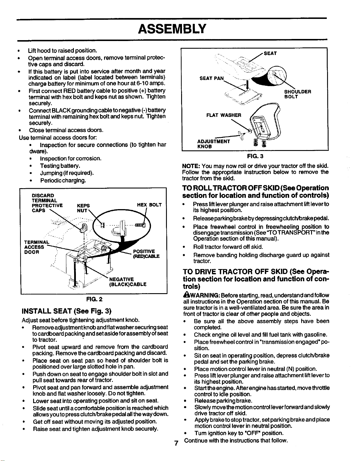
INSTALL SEAT (See Fig. 3)
Adjust seat before tightening adjustment knob.
•Remove adjustment knobandflatwasher securingseat
tocardboard packing andset aside forassembly ofseat
to tractor.
•Pivot seat upward and remove from the cardboard
packing. Remove the cardboard packing and discard.
•Place seat on seat pan so head of shoulder bolt is
positioned over large slottedhole inpan.
•Push down on seat toengage shoulder boltin slotand
pull seat towards rear oftractor.
•Pivot seat and pan forward and assemble adjustment
knob and fiat washer loosely, Do not tighten.
•Lower seat into operating position and siton seat.
•Slide seat untila comfortable positionisreached which
allowsyoutopress clutch/brakepedal alltheway down.
•Get off seat without moving itsadjusted position.
•Raise seat and tighten adjustment knob securely.
7
-_ _ jSEAT
i "_-.._ _'..
% _ "" __ SHOULDER
-_ _ ._'_ BOLT
FLAT WASHER _=_
,o..
KNOB _'_ _
FIG. 3
NOTE: You may now rollor drive your tractor off the sldd.
Follow the appropriata instruction below to remove the
tractor from the skid.
TO ROLL TRACTOR OFF SKID (See Operation
section for location and function of controls)
•Press liftlever plunger and raise attachment liftlever to
itshighest position.
•Release parkingbrakebydepressingclutch/brakepedal.
•Place freewheel control in freewheeling position to
disengage transmission (See "TO TRANSPORT" inthe
Operation section ofthis manual).
Roll tractorforward off skid.
Remove banding holding discharge guard up against
tractor.
TO DRIVE TRACTOR OFF SKID (See Opera-
tion section for location and function of con-
trols)
•kWARNING: Beforestarting, read,understand and follow
all instructionsin the Operation section ofthis manual. Be
sure tractor isin a well-ventilated area. Be sure the area in
frontof tractor isclear of other people and objects.
•Be sure all the above assembly steps have been
completed.
•Check engine oil level and fillfuel tank with gasoline.
•Place freewheel controlin "transmissionengaged" po-
sition.
•Siton seat in operating position, depress clutch/brake
pedal and set the parking brake.
•Place motion controllever in neutral (N) position.
•Press liftlever plunger and raise attachment liftlever to
its highest position.
• Startthe engine. Afterengine has started,movethrottle
controlto idle position.
•Release parkingbrake.
•Slowlymove themotioncontrolleverforward andslowly
ddve tractor off skid.
•Apply breke tostoptractor, set parkingbrake and place
motioncontrollever in neutral position.
•Turn ignitionkey to 'OFF" position.
Continue withthe instructionsthat follow.
ASSEMBLY
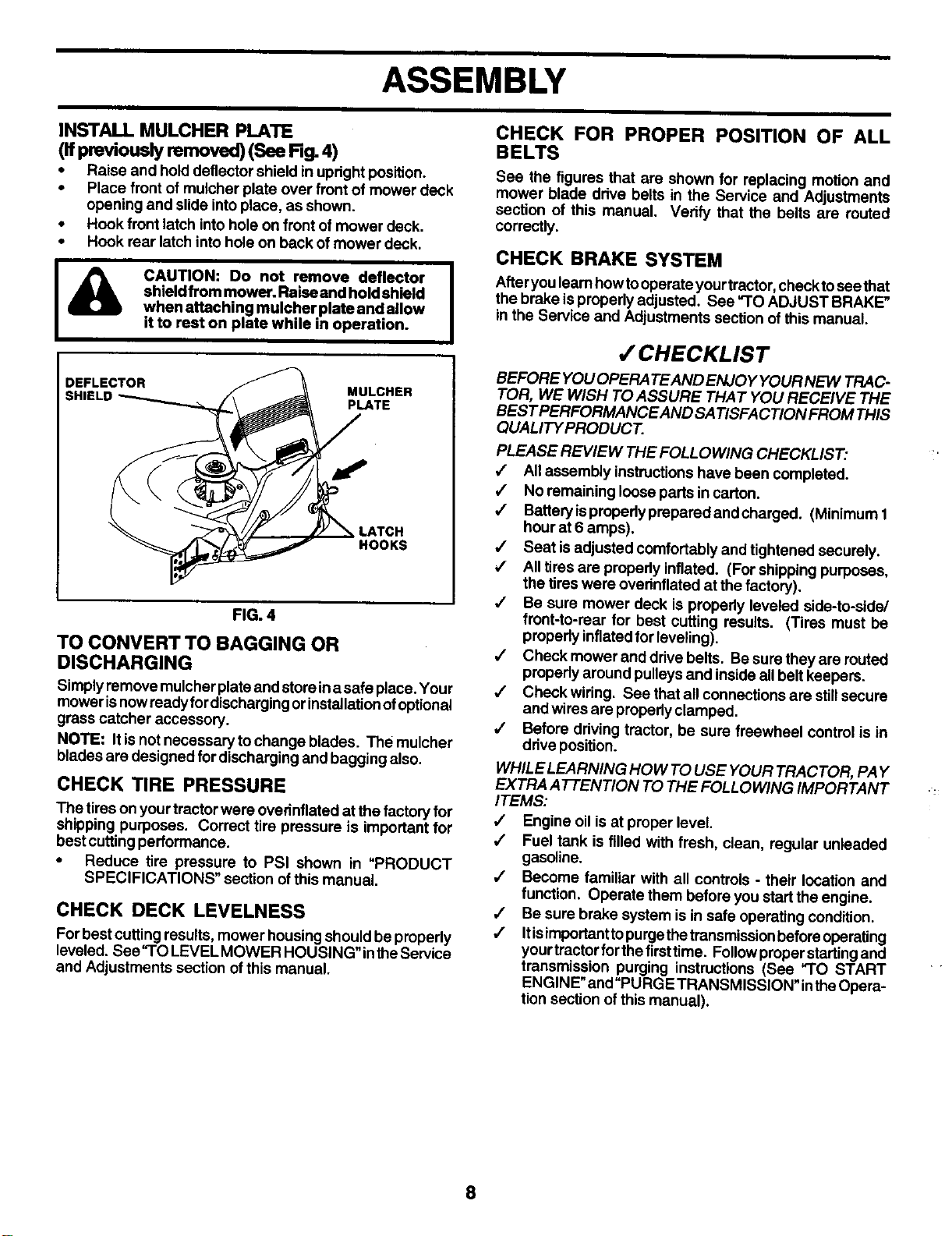
INSTALL MULCHER PLATE
(If previously removed) (See Rg. 4)
• Raise and hold deflector shield in updghtposition.
•Place frontof mulcher plate over front of mower deck
opening and slide intoplace, as shown.
•Hook front latch intohole on front of mower deck.
• Hook rear latch into hole on back ofmower deck.
ACAUTION: Do not remove deflector
shield from mower. Raise and hold shield
when attaching mulcher plate and allow
it to rest on plate while in operation.
DEFLECTOR MULCHER
SHIELD PLATE
LATCH
HOOKS
FIG. 4
TO CONVERT TO BAGGING OR
DISCHARGING
Simplyremove mulcher plate and store ina safe place. Your
mower isnowready for dischargingor installationofoptional
grass c_tcher accessory.
NOTE: Itis not necessary to change blades. The mulcher
blades are designed for discharging and bagging also.
CHECK TIRE PRESSURE
The tires on yourtractor were ovednflated at the factory for
shipping purposes. Correct tire pressure is important for
bestcutting performance.
•Reduce tire pressure to PSI shown in _PRODUCT
SPECIFICATIONS" section ofthis manual.
CHECK DECK LEVELNESS
For bestcutting results, mower housingshould be propedy
leveled. See'q'O LEVEL MOWER HOUSING" intheService
and Adjustments section ofthis manual.
CHECK FOR PROPER POSITION OF ALL
BELTS
See the figures that are shown for replacing motion and
mower blade drive belts in the Service and Adjustments
section of this manual. Verify that the belts are routed
correctly.
CHECK BRAKE SYSTEM
Afteryou leam howtooperate yourtractor,check tosee that
the brake ispropedy adjusted. See "TO ADJUST BRAKE"
in the Service and Adjustments section of this manual.
,/'CHECKLIST
BEFORE YOU OPERA TEAND ENJO Y YOUR NEW TRAC-
TOR, WE WISH TO ASSURE THAT YOU RECEIVE THE
BEST PERFORMANCE AND SATISFACTION FROM THIS
QUALITY PRODUCT.
PLEASE REVIEW THE FOLLOWING CHECKLIST:
/All assembly instructionshave been completed.
JNo remaining loose parts in carton.
,/ Battery isproperly prepared and charged. (Minimum 1
hour at 6 amps).
,/ Seat isadjusted comfortably and tightened securely.
/All tires are properly inflated. (For shippingpurposes,
the tires were ovednflated at the factory).
,/ Be sure mower deck is propedy leveled side-to-side/
front-to-rear for best cutting results. (TIres must be
propedy inflatedfor leveling).
/Check mower and drive belts. Besure they are reuted
propedy around pulleys and inside all belt keepers.
,/ Check wiring. See thatall connections are stillsecure
and wires are propedy clamped.
JBefore driving tractor, be sure freewheel control is in
driveposition.
WHILE LEARNING HOW TO USE YOUR TRACTOR, PAY
EXTRA ATTENTION TO THE FOLLOWING IMPORTANT
ITEMS:
/Engine oil is at proper level
,/ Fuel tank is filled with fresh, clean, regular unleaded
gasoline.
•/ Become familiar with all controls - their location and
function. Operate them before you startthe engine.
/Be sure brake system isin sate operating condition,
/Itisimportanttopurgethetransmissionbeforeoperating
yourtractor forthefirsttime. Followproper startingand
transmission purging instructions (See "TO START
ENGINE" and "PURGE TRANSMISSION" intheOpera-
tion section of this manual).
8
OPERATION
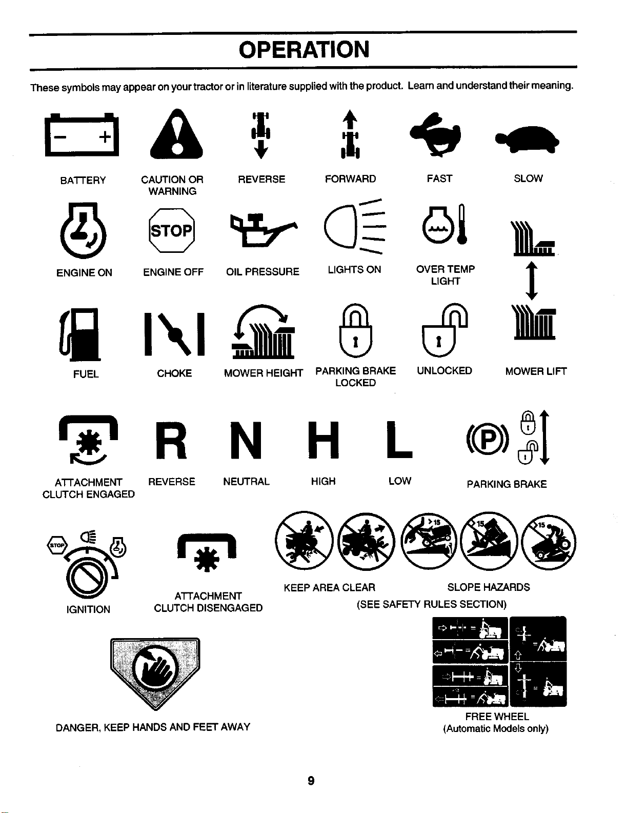
These symbols may appear on yourtractor or in literaturesupplied withthe product. Learn and understand their meaning.
BA'I-rERY CAUTION OR REVERSE FORWARD FAST SLOW
WARNING
ENG,NEONENG,NEOFFO,LPRESSOREL.G.TSON0%T_.P
FUEL CHOKE MOWER HEIGHT PARKING BRAKE UNLOCKED MOWER LIFT
LOCKED
r 'l R N H
A'I-rACHMENT REVERSE
CLUTCH ENGAGED
IGNITION ATTACHMENT
CLUTCH DISENGAGED
NEUTRAL HIGH LOW PARKING BRAKE
KEEP AREA CLEAR SLOPE HAZARDS
(SEE SAFETY RULES SECTION)
DANGER, KEEP HANDS AND FEET AWAY
9
FREE WHEEL
(Automatic Models only)
OPERATION
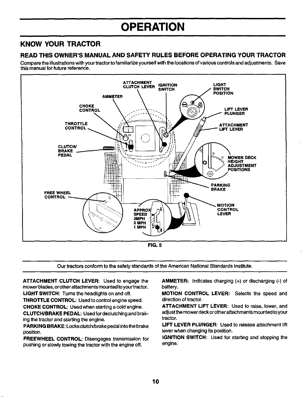
KNOW YOUR TRACTOR
READ THIS OWNER'S MANUAL AND SAFETY RULES BEFORE OPERATING YOUR TRACTOR
Compare theillustrationswith yourtractortofamiliarizeyourself with the locationsofvariouscontrols and adjustments. Save
this manual for future reference,
CHOKE
CONTROL
THROTTLE
CONTROL
ATTACHMENT
CLUTCH LEVER IGNITION LIGHT
SWITCH POSITION
AMMETER
LIFT LEVER
PLUNGER
ATTACHMENT
UFT LEVER
CLUTCH/
BRAKE
PEDAL MOWER DECK
HEIGHT
ADJUSTMENT
POSITIONS
FREE WHEEL
CONTROL
PARKING
BRAKE
CONTROL
LEVER
FIG. 5
Our tractors conform to the safety standards ofthe Amedcan National Standards Institute.
ATFACHMENT CLUTCH LEVER: Used to engage the
mowerbledes, orotherattechments mounted toyour tractor.
LIGHT SWITCH: Tums the headlights on and off.
THROTTLE CONTROL: Used to controlengine speed.
CHOKE CONTROL: Used when startinga coldengine.
CLUTCH/BRAKE PEDAL: Used for declutchingand brak-
ingthe tractor and starting the engine.
PARKING BRAKE: Locksclutch/brake pedalintothebrake
position.
FREEWHEEL CONTROL: Disengages transmission for
pushing or slowlytowing the tractor withthe engine off.
AMMETER: Indicates charging (+) or discharging (-) of
battery.
MOTION CONTROL LEVER: Selects the speed and
direction of tractor.
ATTACHMENT LIFT LEVER: Used to raise, lower, and
adjustthe mower deckorotherattachmentsmounted toyour
tractor.
UFT LEVER PLUNGER: Used to release attachment lift
lever when changing itsposition.
IGNITION SWITCH: Used for starting and stopping the
engine.
10
OPERATION
I _1__ The operation of any tractor can result in foreign objects thrown into the eyes, which can I
r _ GI.ASSr=SI result in severe eye damage. Always wear safety glasses or eye shields while operating I
• JL. • your tractor or performing any adjustments or repairs. We recommend a wide vision |
safety mask over spectacles or standard safety glasses.
HOW TO USE YOUR TRACTOR
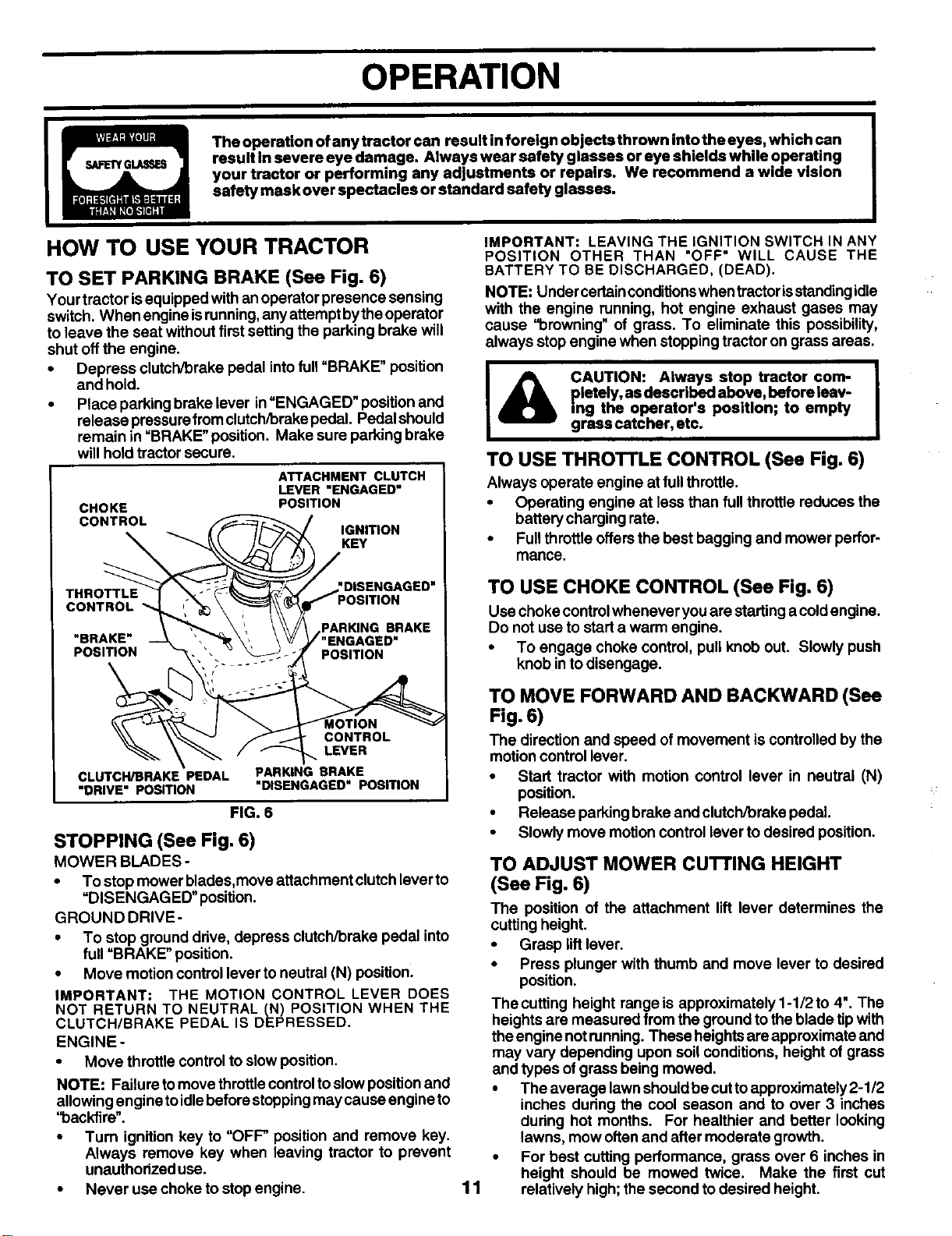
TO SET PARKING BRAKE (See Fig. 6)
Your tractor isequipped with anoperator presence sensing
switch. When engine isrunning,anyattemptbytheoperator
to leave the seat without first settingthe parking brake will
shut offthe engine.
• Depress clutch/brake pedal intofull"BRAKE" position
and hold.
•Place parkingbrake lever in"ENGAGED" position and
release pressurefromclutch/brake pedal. Pedalshould
remain in "BRAKE" position. Make sure parkingbrake
will hold tractor secure.
CHOKE
CONTROL
ATTACHMENT CLUTCH
LEVER "ENGAGED"
POSITION
IGNITION
KEY
CONTROL
"BRAKE"
POSITION
CONTROL
LEVER
CLUTCH/BRAKE PEDAL PARKING BRAKE
"DRIVE" PosmoN "DISENGAGED" POSITION
FIG. 6
STOPPING (See Fig. 6)
MOWER BLADES-
•To stop mower blades,move attachment clutch lever to
"DISENGAGED" position.
GROUND DRIVE-
•To stop ground drive, depress clutch/brake pedal into
full "BRAKE" position.
• Move motion control lever to neutral (N) position.
IMPORTANT: THE MOTION CONTROL LEVER DOES
NOT RETURN TO NEUTRAL (N) POSITION WHEN THE
CLUTCH/BRAKE PEDAL IS DEPRESSED.
ENGINE-
• Move throttle controlto slow position.
NOTE: Failure to move throttle control to slow position and
allowing engine to idle before stopping may cause engine to
'1oackfire".
•Tum ignition key to "OFF" position and remove key.
Always remove key when leaving tractor to prevent
unauthorized use.
•Never use choke to stop engine.
IMPORTANT: LEAVING THE IGNITION SWITCH IN ANY
POSITION OTHER THAN "OFF" WILL CAUSE THE
BATTERY TO BE DISCHARGED, (DEAD).
NOTE: Under certainconditionswhen tractorisstandingidle
with the engine running, hot engine exhaust gases may
cause '10rowning"of grass. To eliminate this possibility,
always stop engine when stopping tractor on grass areas.
CAUTION: Always stop tractor com- I
pletely, as described above, before leav-
ing the operator's position; to empty
grass catcher, etc.
TO USE THRO'n'LE CONTROL (See Fig. 6)
Always operate engine at fullthrottle.
•Operating engine at less than full throttle reduces the
battery charging rate.
•Full throttle offersthe best bagging and mower perfor-
mance.
11
TO USE CHOKE CONTROL (See Fig. 6)
Use choke controlwhenever you are startinga coldengine.
Do not use to start a warm engine.
•To engage choke control, pull knob out. Slowly push
knob in todisengage.
TO MOVE FORWARD AND BACKWARD (See
Fig. 6)
The direction and speed of movement is controlledby the
motioncontrol lever.
•Start tractor with motion control lever in neutral (N)
position.
• Release parking brake and clutch/brake pedal.
•Slowly move motion control lever to desired position.
TO ADJUST MOWER cu'n'ING HEIGHT
(See Fig. 6)
The position of the attachment lift lever determines the
cuffing height.
•Grasp lift lever.
•Press plunger with thumb and move lever to desired
position.
The cuffing height range is approximately 1-1/2 to 4". The
heights are measured from the ground to the blade tip with
theengine not running.These heightsare approximate and
may vary depending upon soil conditions, height of grass
and types of grass being mowed.
•The average lawn shouldbe cutto approximately 2-1/2
inches during the cool season and to over 3 inches
during hot months. For healthier and better looking
lawns, mow often and after moderate growth.
• For best cutting performance, grass over 6 inches in
height should be mowed twice. Make the first cut
relatively high; the second to desired height.
OPERATION
TO OPERATE ON HILLS
TO ADJUST GAUGE WHEELS (See Fig. 7)
Gauge wheels are properly adjusted when they are slightly
offthe ground when mower isat thedesired cuttingheight in
operating position. Gauge wheels then keep the deck in
proper position to help prevent scalping in most terrain
conditions.
• Adjust gauge wheels with tractoron a flatlevel surface.
•Adjust mower to desired cutting height (See "TO AD-
JUST MOWER CUq-I'ING HEIGHT" in the Operation
section of this manual).
•With mower in desired height of cut position, gauge
wheels shouldbe assembled sothey are slightlyoffthe
ground. Install gauge wheel in appropriate hole with
shoulderbolt,3/8 washer, and 3/8-16 Iocknutandtighten
securely.
•Repeat foroppositeside installinggauge wheel insame
adjustment hole.
3/8-16
GUAGE WHEEL
MOUNTING
3/8 WASHF-I =
GAUGE WHEEl,:
SHOULDER
BOLT
FIG. 7
TO OPERATE MOWER (See Fig. 8)
Yourtractor isequipped withan operator presence sensing
switch. Any attempt by the operator to leave the seat with
the engine runningand the attachment clutchengaged will
shut off the engine.
• Select desired height of cut.
•Start mower blades by engaging attachment clutch
control.
•TO STOP MOWER BLADES - disengage attachment
clutch control.
I_IL CAUTION: Do not operate the mower I
wlthout either the enUre grass catcher, I
on mowers so equipped, or the dis-
charge guard in place.
"ENGAGED" POSITION
ATTACHMENT
HIGH POSI-
/:/ TION
./._- LOW
// POSITION
DISCHARGE
GUARD
CLUTCH LEVER
"DISENGAGED"
POSITION
CAUTION: Do not drive up or down hills I
with slopes greater than 15° and do not
drive across any slope.
•Choose the slowest speed before starting up or down
hills.
•Avoid stopping or changing speed on hills.
•If slowing is necessary, move throttle control lever to
slower position.
•Ifstopping is absolutely necessary, push clutch/brake
pedal quickly to brake position and engage parking
brake.
•Move motion control lever to neutral (N) position.
IMPORTANT: THE MOTION CONTROL LEVER DOES
NOT RETURN TO NEUTRAL (N) POSITION WHEN THE
CLUTCH/BRAKE PEDAL IS DEPRESSED.
•To restartmovement, slowlyrelease parking brake and
clutch/brake pedal.
•Slowly move motion controllever to slowest setting.
• Make all turns slowly.
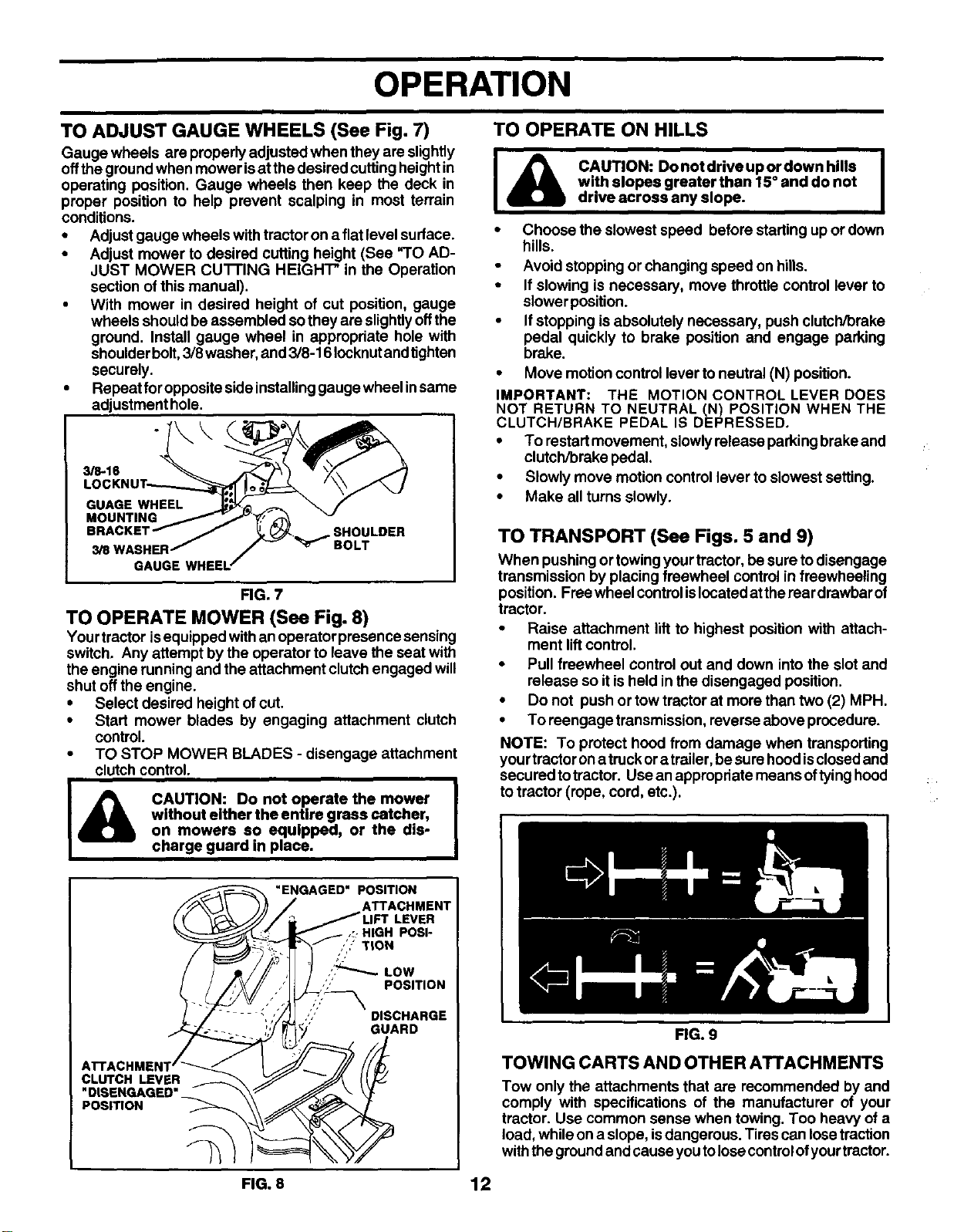
TO TRANSPORT (See Figs. 5 and 9)
When pushing or towing yourtractor, be sure todisengage
transmission by placing freewheel control in freewheeling
position. Free wheel controlis locatedatthe rear drawbar of
tractor.
•Raise attachment lift to highest position with attach-
ment liftcontrol.
•Pull freewheel control out and down intothe slot and
release so it isheld inthe disengaged position.
•Do not push or tow tractor at more than two (2) MPH.
•To reengage transmission, reverse above procedure.
NOTE: To protect hood from damage when transporting
yourtractorona truckor atrailer, besure hood isclosedand
secured totractor. Use anappropriate means oftyinghood
to tractor (rope, cord, etc.).
FIG. 9
TOWING CARTS AND OTHER ATTACHMENTS
Tow only the attachments that are recommended by and
comply with specifications of the manufacturer of your
tractor. Use common sense when towing. Too heavy of a
load, while ona slope, is dangerous. Tirescan losetraction
withthe groundand cause youtolosecontrolofyourtractor.
FIG. 8 12
OPERATION
BEFORE STARTING THE ENGINE
CHECK ENGINE OIL LEVEL (See Fig. 14)
• The engine in yourtractor has been shipped, from the
factory, already filled with summer weight oil.
• Check engine oil with tractor on level ground.
•Remove oilfillcap/dipstick and wipe clean, reinsert the
dipstick and screw cap tight, wait for a few seconds,
remove and read oil level. If necessaP/, add oil until
"FULL" mark on dipstick isreached. Do not overfill.
•For cold weather operation you should change oil for
easier starting (See =OIL VISCOSITY CHART" in the
Customer Responsibilities section ofthis manual).
•Tochange engineoil,seethe Customer Responsibilities
section in this manual.
ADD GASOLINE
•Fill fuel tank. Use fresh, clean, regular unleaded
gasoline with a minimum of87 octane. (Use of leaded
gasoline willincrease carbon and lead oxide deposits
and reduce valve life). Do not mix oil with gasoline.
Purchase fuel in quantities that can be used within 30
days to assure fuel freshness.
IMPORTANT: WHEN OPERATING IN TEMPERATURES
BELOW 32°F(0°C), USE FRESH, CLEAN WINTER GRADE
GASOLINE TO HELP INSURE GOOD COLD WEATHER
STARTING.
WARNING: Experience indicatesthatalcoholblendedfuels
(called gasohol or using ethanol or methanol) can attract
moisture which leads to separation and formation of acids
during storage. Acidicgas can damage the fuel system of
an engine while in storage. To avoid engine problems, the
fuel system should be emptied before storage of30 days or
longer. Drain the gastank, starttheengine and letitrununtil
thefuel linesand carburetor are empty. Use fresh fuel next
season. See Storage Instructionsforadditionalinformation.
Never use engine or carburetor cleaner productsin thefuel
tank or permanent damage may occur.
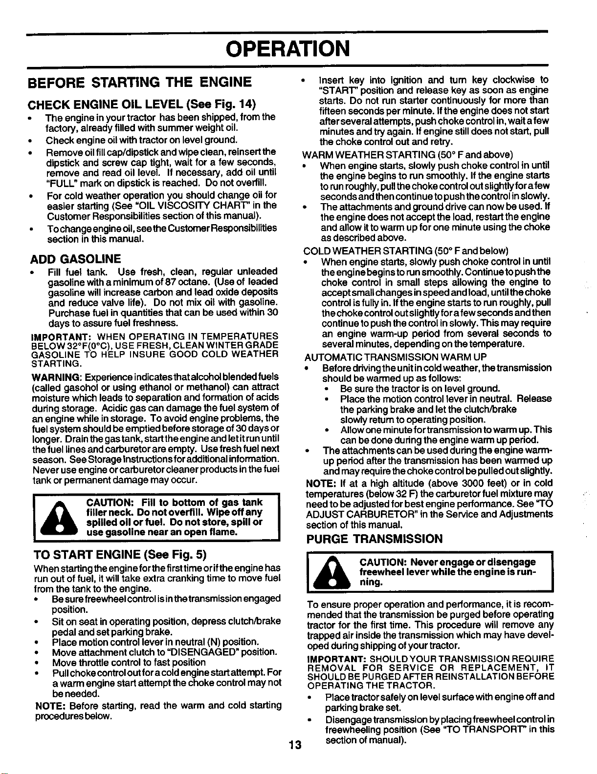
I_IL AUTION: Fill to bottom of gas tank I
filler neck. Do not overfill. Wipe offany I
spilled oil or fuel. Do not store, spill or
use gasoline near an open flame.
TO START ENGINE (See Fig, 5)
When startingtheengine forthe firsttime oriftheengine has
run out of fuel, itwilltake extra cranking time to move fuel
from the tank tothe engine.
•Besurefreewheelcontml isinthetransmission engaged
position.
•Sit on seat inoperating position,depress clutch/brake
pedal and set parking brake.
•Place motioncontrol lever in neutral (N) position.
•Move attachment clutch to =DISENGAGED" position.
•Move throttle control to fast position
•Pullchoke control out for acold engine startattempt. For
a warm engine start attempt the choke control may not
beneeded.
NOTE: Before starting, read the warm and cold starting
procedures below.
•Insert key into ignition and tum key clockwise to
"START" positionand release key as soon as engine
starts. Do not run starter continuously for more than
fifteen secondsper minute, ifthe engine does not start
after several attempts, pushchoke controlin, waita few
minutes and tryagain. If engine stilldoes not start, pull
the choke controlout and retry.
WARM WEATHER STARTING (50 ° Fand above)
•When engine starts, slowly push choke control in until
the engine begins to runsmoothly. If the engine starts
torunroughly,pullthe choke controloutslightlyfor afew
seconds andthen continue topushthe controlinslowly.
•The attachments and ground drive can now be used. If
the engine does not accept the load, restart the engine
and allow ittowarm up for one minute usingthe choke
as described above.
13
COLD WEATHER STARTING (50 ° Fand below)
• When engine starts, slowlypush choke control in until
the engine begins torunsmoothly.Continue topushthe
choke control in small steps allowing the engine to
accept smallchanges inspeed and load, untilthechoke
controlisfullyin. Ifthe engine startsto run roughly,pull
thechoke controloutslightlyfor afew seconds andthen
continue topushthe control inslowly. This may require
an engine warm-up period from several seconds to
several minutes, depending on thetemperature.
AUTOMATIC TRANSMISSION WARM UP
•Beforeddvingthe unitincoldweather, the transmission
should be warmed up as follows:
•Be sure the tractor is on level ground.
• Place the motion control lever in neutral. Release
the parkingbrake and let the clutch/brake
slowly returntooperating position.
•Allow one minutefortransmission towarm up.This
can be done during the engine warm up pedod.
•The attachments can be used duringthe engine warm-
up period after the transmission has been warmed up
and may requirethe choke controlbepulledout slightly.
NOTE: If at a high altitude (above 3000 feet) or in cold
temperatures (below 32 F) the carburetor fuel mixture may
need to be adjustedfor best engine performance. See "TO
ADJUST CARBURETOR" in the Service and Adjustments
section of this manual.
PURGE TRANSMISSION
I_k AUTION: Neverengageordisengage J
freewheel lever while the engine is run-
ning.
To ensure proper operation and performance, itis recom-
mended that the transmission be purged before operating
tractor for the first time. This procedure will remove any
trapped air inside the transmission which may have devel-
oped during shippingofyour tractor.
IMPORTANT: SHOULDYOURTRANSMISSION REQUIRE
REMOVAL FOR SERVICE OR REPLACEMENT, IT
SHOULD BEPURGED AFTER REINSTALLATION BEFORE
OPERATING THE TRACTOR.
•Place tractorsafelyon level surface withengine off and
parkingbrake set.
•Disengage transmission byplacingfreewheel controlin
freewheeling position (See -TO TRANSPORT" in this
section ofmanual).
OPERATION
• Sifting in the tractor seat, startengine. After the engine
is running, move throttle controlto slow position. With
motion control lever in neutral (N) position, slowly
disengage clutch/brake pedal.
•Move motion control lever to full forward position and
hold for five (5) seconds. Move lever to full reverse
position and hold for five (5) seconds. Repeat this
procedure three (3) times.
NOTE: During this procedure there willbe no movement of
drive wheels. The air isbeing removed from hydraulic drive
system.
•Move motion control lever toneutral (N) position. Shut-
offengine and set parking brake.
• Engage transmission by placing freewheel control in
drivingposition (See "TO TRANSPORT" inthissection
ofmanual).
• Sitting in thetractor seat, start engine. After the engine
isrunning, movethrottlecontroltohalf (1/2) speed. With
motion control lever in neutral (N) position, slowly
disengage clutch/brake pedal.
•Slowly move motion control lever forward, after the
tractor moves approximately five (5) feet, slowlymove
motioncontrollever toreverse position.After thetractor
moves approximately five (5) feet return the motion
control lever to the neutral (N) position. Repeat this
procedure with the motioncontrolleverthree (3) times.
•Your tractor is now purged and now ready for normal
operation.
MOWING TIPS
•Mower should be properly leveled for best mowing
performance. See "TO LEVEL MOWER HOUSING" in
the Service and Adjustments section of this manual.
•The lefthand sideofmower shouldbeused for trimming.
•Driveso thatclippingsare discharged ontothe areathat
has been cut. Have the cut area to the right of the
machine. This will resultin a more even distributionof
clippingsand more uniformcutting.
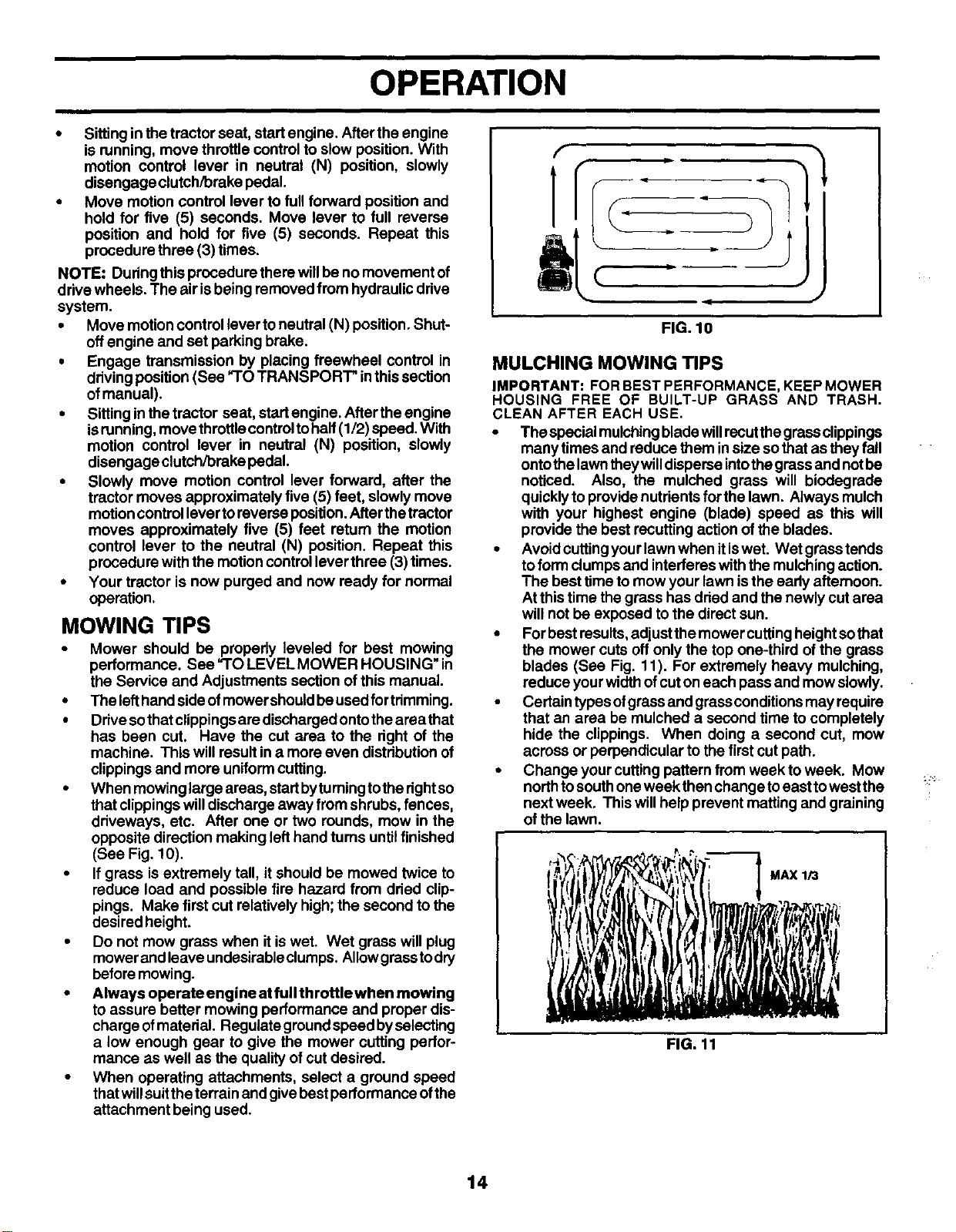
•When mowinglarge areas, startbytumingtothe dght so
thatclippingswill discharge away from shrubs, fences,
driveways, etc. After one or two rounds, mow in the
opposite direction making left hand tums untilfinished
(See Fig. 10).
•If grass isextremely tall, it should be mowed twice to
reduce load and possible fire hazard from dried clip-
pings. Make first cut relatively high;the second to the
desired height.
•Do not mow grass when itis wet. Wet grass will plug
mower and leave undesirableclumps. Allowgrass todry
beforemowing.
•Always operate engine at full throttle when mowing
to assure better mowing performance and proper dis-
charge ofmaterial. Regulate ground speed byselecting
a low enough gear to give the mower cutting perfor-
mance as well as the quality of cut desired.
•When operating attachments, select a ground speed
thatwillsuitthe terrain and give bestperformance ofthe
attachment being used.
t
FIG. 10
J
MULCHING MOWING TIPS
IMPORTANT: FOR BEST PERFORMANCE, KEEP MOWER
HOUSING FREE OF BUILT-UP GRASS AND TRASH.
CLEAN AFTER EACH USE.
•The specialmulchingblade willrecutthe grassclippings
manytimes and reduce them in size sothat as they fall
ontothe lawn they willdisperse intothe grass and notbe
noticed. Also, the mulched grass will biodegrade
quickly to providenutrients for the lawn. Always mulch
with your highest engine (blade) speed as this will
provide the best recutting actionof the blades.
•Avoid cuttingyourlawn when itiswet. Wet grass tends
toform clumps and interferes withthe mulching action.
The best timeto mow your lawn isthe early afternoon.
At this time the grass has dried and the newly cutarea
will not be exposed to the direct sun.
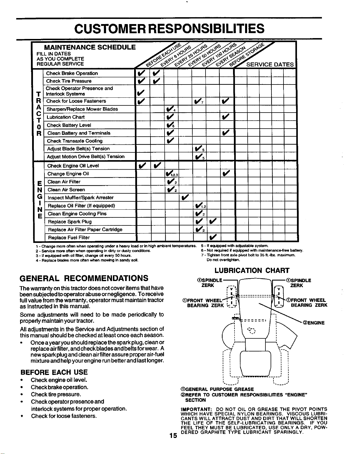
•Forbest results,adjust the mower cuttingheight sothat
the mower cuts off only the top one-third of the grass
blades (See Fig. 11). For extremely heavy mulching,
reduce yourwidthof cuton each pass and mow slowly.
•Certain types ofgrass and grassconditionsmay require
that an area be mulched a second time to completely
hide the clippings. When doing a second cut, mow
across or perpendicular to the first cut path.
•Change your cutting pattern from week to week. Mow
northto southone week then change toeast towest the
next week. This will help prevent matting and graining
of the lawn.
MAX 1_
FIG. 11
14
CUSTOMER RESPONSIBILITIES
.A,NTENANCESC.EOU'E "
AS YOU COMPLETE
REGUlaRSERV,CE ......
Y f , SERV'CE DATES
Check Brake Operation _
Check Tire Pressure
Check Operator Presence and
TInterlock Systems
Check for Loose Fasteners 11_7
A SharperVReplace Mower Blades _4
Lubrication Chart
T Check Battery Level
RClean Battery and Terminals V'
Check Transaxle Cooling V'
Adjust Blade Belt(s) Tension V'5
Adjust Motion Drive Belt(s) Tension I_'s
Check Engine Oil Level _I1_
Change Engine Oil _1,2,3 V=
EClean Air Filter 11_2
NJ Clean Air Screen I_2
GInspect Muffler/Spark An'ester Ii_
NI Replace Oil Filter (If equipped) _1,2
EClean Engine Cooling Fins V=2
Replace Spark Plug _/_2
Replace Air Filter Paper Cartridge
Replace Fuel Filter V#
1 - Change more often when operating under a heavy load or in high ambient temperatures, 5 -If equipped wi_ adjustable system.
2 - Service more often when operating in dirtyor dusty conditions. 6 - Not requ_rad if equipped with maintenance-free baser/,
3 - if equipped with oil fl_er, change oil every 50 hours, 7 - "llghten front axle pivot bolt to 35 fL-Ibs, maximum,
4-Replace b_ades more often when mowing in sandy soil. Do not overtlghten.
GENERAL RECOMMENDATIONS
The warranty on thistractordoes notcover items thathave
been subjected tooperator abuse ornegligence. To receive
fullvalue from the warranty, operator mustmaintain tractor
as instructed in this manual.
Some adjustments will need to be made periodically to
properly maintainyour tractor.
All adjustments inthe Service and Adjustments section of
this manual shouldbe checked at leastonce each season.
•Once ayearyou shouldreplacethe spark plug,clean or
replace airfilter,and check blades and beltsfor wear. A
new spark plugand clean airfilter assure proper air-fuel
mixtureand helpyourengine runbetter and lastlonger.
BEFORE EACH USE
•Check engine oillevel.
•Check brakeoperation.
•Check tire pressure,
•Check operator presence and
interlocksystems for proper operation.
•Check for loosefasteners.
LUBRICATION CHART
ZERK ZERK
(1)FRONT
BEARING ZERK "(_)FRONTWHEEL
BEARING ZERK
15
L'DGENERAL PURPOSE GREASE
_)REFER TO CUSTOMER RESPONSIBILITIES "ENGINE"
SECTION
IMPORTANT: DO NOT OIL OR GREASE THE PIVOT POINTS
WHICH HAVE SPECIAL NYLON BEARINGS. VISCOUS LUBRI-
CANTS WILL ATTRACT DUST AND DIRT THAT WILL SHORTEN
THE LIFE OF THE SELF-LUBRICATING BEARINGS. IF YOU
FEEL THEY MUST BE LUBRICATED, USE ONLY A DRY, POW-
DERED GRAPHITE TYPE LUBRICANT SPARINGLY.
CUSTOMER RESPONSIBILITIES
TRA|LtNG
"uP
TRACTOR
Always observe safety rules when performing any mainte-
nance.
BRAKE OPERATION
Iftractorrequiras more than six (6) feet stopping distance at
high speed in highest gear, then brake must be adjusted.
(See "TO ADJUST BRAKE" intheService and Adjustrnents
section of this manual).
TIRES
•Maintainproper airpressure inalltires (See"PRODUCT
SPECIFICATIONS" section ofthis manual).
•Keep tiresfree of gasoline, oil, orinsect control chemi-
cals which can harm rubber.
•Avoid stumps, stones, deep ruts, sharp objects and
other hazards that may cause tiredamage.
NOTE: To seal tire punctures and prevent flat tires due to
slow leaks, tire sealant may be purchased from your local
parts dealer. Tire sealant also prevents tire dry rot and
corrosion.
OPERATOR PRESENCE SYSTEM
Be sureoperator presence and interlock systems are work-
ingproperly. Ifyourtractor does not function as described,
repair the problemimmediately.
•The engine should not start unless the clutch/brake
pedal isfully depressed and attachement clutchcontrol
is inthe disengaged position.
•When theengine isrunning, anyattempt bythe operator
to leave the seat without first setting the parking brake
should shut offthe engine.
• When the engineis running andthe attachment clutchis
engaged, any attempt by the operator to leave the seat
should shut off the engine.
• The attachment clutch shouldnever operate unless the
operator is in the seat.
BLADE CARE
Forbest resultsmower blades mustbe keptsharp. Replace
bent or damaged blades.
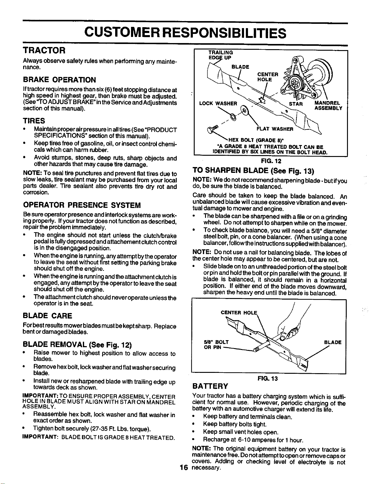
BLADE REMOVAL (See Fig. 12)
• Raise mower to highest position to allow access to
blades.
• Removehexbolt, leckwasherandflatwashersecudng
blade.
• Install new or resharpaned blade with trailing edge up
towards deck as shown.
IMPORTANT: TO ENSURE PROPER ASSEMBLY, CENTER
HOLE IN BLADE MUST ALIGN WITH STAR ON MANDREL
ASSEMBLY.
•Reassemble hex bolt, lockwasher and flat washer in
exact order as shown.
•Tighten boltsecurely (27-35 Ft. Lbs. torque).
IMPORTANT: BLADE BOLT ISGRADE 8 HEAT TREATED.
BLADE
CENTER
HOLE
16
LOCK WASHER STAR MANDREL
ASSEMBLY
f
FLAT WASHER
HEX BOLT (GRADE 8)*
*A GRADE 8 HEAT TREATED BOLT CAN BE
IDENTIFIED BY SIX LINES ON THE BOLT HEAD.
FIG. 12
TO SHARPEN BLADE (See Fig. 13)
NOTE: We donot recommend sharpeningblade -but ifyou
do, be sure the blade is balanced.
Care should be taken to keep the blade balanced. An
unbalanced blade willcause excessive vibration and even-
tual damage to mower and engine.
• The blade can be sharpened with a file or on a grinding
wheel. Do not attempt to sharpen while on the mower.
• To check blade balance, you will need a 5/8" diameter
steel bolt, pin, or a cone balancer. (When using a cone
balancer, follow the Instructions supplied with balancer).
NOTE: Do notuse a nail for balancing blade. The lobes of
the center hole may appear tobe centered, but are not.
•Slide blade onto an unthreaded portionofthe steel bolt
or pinand hold theboltor pinparallelwith the ground. If
blade is balanced, it should remain in ahorizontal
position. If either end of the blade moves downward,
sharpen the heavy end until theblade isbalanced.
CENTER HOLE //
5/8" BOLT_ BLADE
OR PIN _
FIG. 13
BATTERY
Your tractor has a battery charging system which is suffi-
cient for normal use. However, periodic charging of the
battery with an automotive charger will extend itslife.
•Keep battery and terminals clean.
•Keep battery bolts tight.
•Keep small vent holes open.
•Recharge at 6-10 amperes for 1hour.
NOTE: The odginal equipment battery on your tractor is
maintenance free. Do notattemptto open orremove caps or
covers. Adding or checking level of electrolyte is not
necessary.
CUSTOMER RESPONSIBILITIES
TO CLEAN BATTERY AND TERMINALS
Corrosionand dirtonthe batteryand terminalscancause the
battery to"leak" power.
•Open battery box door.
•Disconnect BLACKbatterycable first then RED battery
cable and remove battery from tractor.
• Rinse the battery with plain water and dry.
•Clean terminals and battery cable ends with wire brush
untilbdght.
•Coat terminals with grease or petroleum jelly.
•Reinstall battery (See "CONNECT BATFERY" in the
Assembly section of this manual).
V-BELTS
Check V-belts for deterioration and wear after t00 hours of
operation and replace if necessary. The belts are not
adjustable. Replace belts ifthey begin to slipfrom wear.
TRANSAXLE COOLING
The transmission fan and cooling fins should be kept clean
toassure proper cooling.
Do not attempt to clean fan or transmission whileengine is
runningorwhilethe transmissionishot.To prevent possible
damage to seals, do not use high pressure water or steam
to clean transaxle.
•inspect coolingfan to be sure fan blades are intact and
clean.
•Inspect cooling fins for dirt, grass clippings and other
materials. To prevent damage to seals, do not use
compressed airorhighpressuresprayertoclean cooling
fins.
TRANSAXLE PUMP FLUID
The transaxle was sealed at the factory and fluid mainte-
nance is not required forthe life of the transaxle. Should the
transaxle ever leakor require servicing,contact your nearest
authorized service center/department.
ENGINE
LUBRICATION
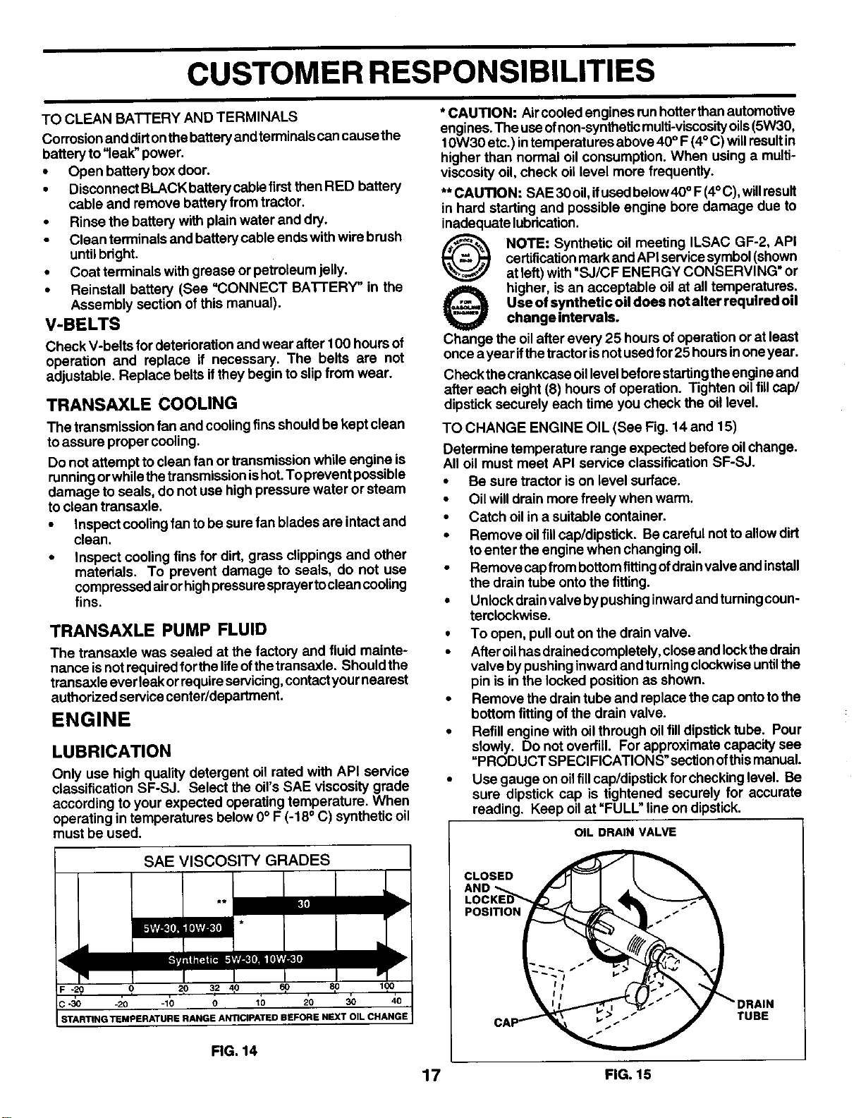
Only use high quality detergent oil rated with API service
classification SF-SJ. Select the oil's SAE viscosity grade
according to your expected operating temperature. When
operating in temperatures below 0° F (-18° C) synthetic oil
must be used.
SAEVISCOSI'rYGRADES
•"m
"ttj _li['..ll[oll; e_il]lill|ti [([I
rq
F-20 . ? 20 32 4p 60 _ 170
c-_o -2o -_b o _b _o _o _o
STARTING'tEMPERATURE RANGE ANTICIPATED BEFORE NEXT OIL CHANGE
FIG. 14
* CAUTION: Air cooled engines runhotter thanautomotive
engines. The useofnon-synthetic multi-viscosityoils(5W30,
t 0W30 etc.) intemperatures above 40 °F (4° C)willresultin
higher than normal oil consumption. When using a multi-
viscosity oil, check oil level more frequently.
** CAUTION: SAE 30 oil,ifused below40° F(4°C), willresult
In hard starting and possible engine bore damage due to
inadequate lubrication.
QNOTE: Synthetic oil meeting ILSAC GF-2, API
certificationmark and API service symbol(shown
at left) with "SJ/CF ENERGY CONSERVING" or
Ohigher, is an acceptable oil at all temperatures.
Use of synthetic oil does not alter required oil
change Intervals.
Change the oilafter every 25 hours ofoperation or at least
once ayear ifthetractorisnot used for 25 hoursinoneyear.
Check the crankcase oillevel before startingthe engine and
after each eight (8) hours of operation. Tighten oilfill cap/
dipstick securely each time you check the oil level.
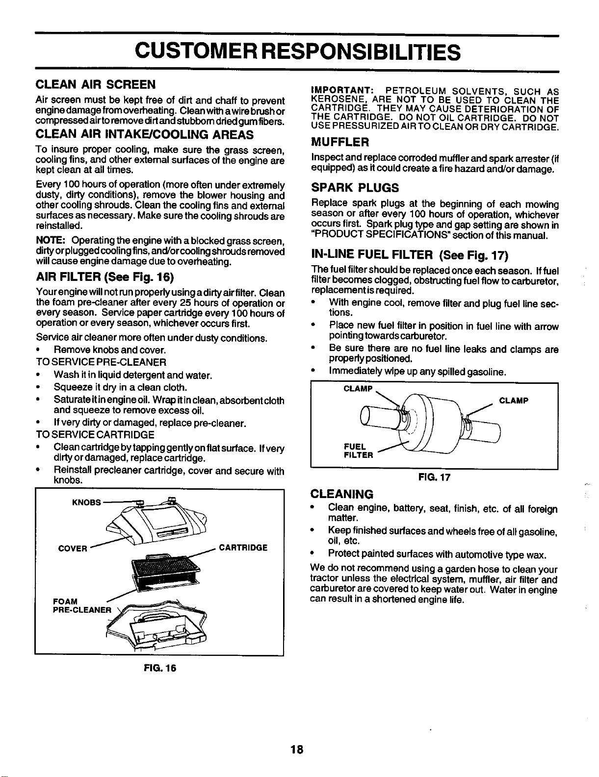
TO CHANGE ENGINE OIL (See Fig. 14 and 15)
Determine temperature range expected before oilchange.
All oil must meet API service classification SF-SJ.
•Be sure tractor is on level surface.
•Oil willdrain more freely when warm.
•Catch oil in a suitable container.
*Remove oilfillcap/dipstick. Be careful not to allow dirt
to enter the engine when changing oil.
• Remove cap from bottom fitting of drain valve and install
the drain tube onto the fitting.
•Unlock drain valve by pushing inward and turning coun-
terclockwise.
.To open, pull out on the drain valve.
• After oil has drained completely, close and lock thedrain
valve by pushing inward and turning clockwise until the
pin is in the locked posiUon as shown.
• Remove the drain tube and replace the cap onto to the
bottom fitting of the drain valve.
• Refill engine with oil through oil fill dipstick tube. Pour
slowly. Do not overfill. For approximate capacity see
"PRODUCT SPECIFICATIONS" sectionofthis manual.
•Use gauge onoilfill cap/dipsUckfor checking level. Be
sure dipstick cap is tightened securely for accurate
reading. Keep oilat "FULL" line on dipstick.
OIL DRAIN VALVE
CLOSED
POSITION
TUBE
17 FIG. 15
CUSTOMER RESPONSIBILITIES
CLEAN AIR SCREEN
Air screen must be kept free of dirt and chaff to prevent
engine damage fromoverheating. Clean witha wirebrushor
compressed airto remove dirtand stubbomdried gumfibers.
CLEAN AIR INTAKE/COOLING AREAS
To insure proper cooling, make sure the grass screen,
cooling fins, and other external surfaces ofthe engine are
kept clean at all times.
Every 100 hours of operation (more often under extremely
dusty, dirty conditions), remove the blower housing and
other cooling shrouds. Clean the cooling fins and external
surfaces as necessary. Make sure the cooling shroudsare
reinstalled.
NOTE: Operating the engine with a blocked grass screen,
dirtyorpluggedcoolingfins,and/orcooling shroudsremoved
willcause engine damage due tooverheating.
AIR FILTER (See Fig. 16)
Your engine willnotrunproperlyusing a dirtyairfilter. Clean
the foam pre-cleaner after every 25 hours of operation or
every season. Service paper cartridge every 100 hours of
operation or every season, whichever occursfirst.
Service air cleaner more often under dusty conditions.
•Remove knobs and cover.
TO SERVICE PRE-CLEANER
•Wash itin liquiddetergent and water.
•Squeeze itdry in a clean cloth.
•Saturateitinengineoil. Wrapitinclean, absorbentcloth
and squeeze to remove excess oil.
•Ifvery dirtyor damaged, replace pre-cleaner.
TO SERVICE CARTRIDGE
•Clean cartddge bytappinggently onflatsurface. Ifvery
dirtyor damaged, replace cartridge.
•Reinstall precleaner cartridge, cover and secure with
knobs.
_CARTRIDGE
;OE; LEA"E
FIG. 16
IMPORTANT: PETROLEUM SOLVENTS, SUCH AS
KEROSENE, ARE NOT TO BE USED TO CLEAN THE
CARTRIDGE. THEY MAY CAUSE DETERIORATION OF
THE CARTRIDGE. DO NOT OIL CARTRIDGE. DO NOT
USE PRESSU RIZED AIR TO CLEAN OR DRY CARTRIDGE.
MUFFLER
Inspect and replace corroded mufflerand spark arrester (if
equipped) as itcould create a fire hazard and/or damage.
SPARK PLUGS
Replace spark plugs at the beginning of each mowing
season or after every 100 hours of operation, whichever
occurs first. Spark plug type and gap setting are shown in
"PRODUCT SPECIFICATIONS" section ofthis manual.
IN-LINE FUEL FILTER (See Fig. 17)
The fuel filtershould be replaced once each season. Iffuel
filterbecomes clogged, obstructingfuel flow to carburetor,
replacement isrequired.
•With engine cool, remove filterand plug fuel line sec-
tions.
•Place new fuel filterin position in fuel line with arrow
pointingtowardscarburetor.
•Be sure there are no fuel line leaks and clamps are
propedypositioned.
•Immediately wipe up any spilledgasoline.
CLAMP
CLAMP
FUEL _/
FILTER °
FIG. 17
CLEANING
•Clean engine, battery, seat, finish, etc. of all foreign
matter.
•Keep finished surfaces and wheels free ofall gasoline,
oil, etc.
•Protect painted surfaces with automotive type wax.
We do not recommend using a garden hose to clean your
tractor unless the electrical system, muffler, air filter and
carburetor are covered to keep water out. Water in engine
can resultin a shortened engine life.
18
SERVICE AND ADJUSTMENTS
CAUTION: BEFORE PERFORMING ANY SERVICE OR ADJUSTMENTS:
• Depress clutch/brake pedal fully and set parking brake.
• Place motion control lever In neutral (N) position.
•Place attachment clutch in "DISENGAGED" position.
•Turn ignitlon key "OFF" and remove key.
•Make sure the blades and all moving parts have completely stopped.
•Disconnect spark plug wire from spark plug and place wire where it cannot come In contact
with plug.
TRACTOR
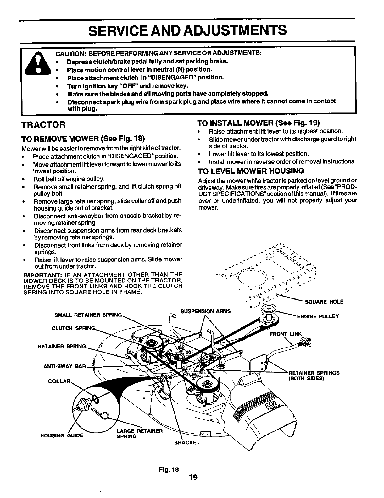
TO REMOVE MOWER (See Fig. 18)
Mower will beeasier toremove from therightside oftractor.
•Place attachment clutch in "DISENGAGED" position.
•Move attachment liftlever forward tolower mower toits
lowest position.
•Roll belt off engine pulley.
• Remove small retainer spring, and liftclutchspring off
pulley bolt.
•Remove large retainer spnng, slide collaroff and push
housing guide out of bracket.
•Disconnect anti-swaybar from chassis bracket by re-
moving retainer spdng.
•Disconnect suspension arms from rear deck brackets
by removing retainer springs.
•Disconnect front linksfrom deck by removing retainer
spnngs.
•Raise lift lever to raise suspension arms. Slide mower
outfrom under tractor.
IMPORTANT: IF AN ATTACHMENT OTHER THAN THE
MOWER DECK IS TO BE MOUNTED ON THE TRACTOR,
REMOVE THE FRONT LINKS AND HOOK THE CLUTCH
SPRING INTO SQUARE HOLE IN FRAME.
TO INSTALL MOWER (See Fig. 19)
•Raise attachment lift lever to its highest position.
•Slide mower under trector withdischarge guard to dght
side oftractor.
•Lower lift lever to its lowest position.
•Install mower in reverse order of removal instructions.
TO LEVEL MOWER HOUSING
Adjustthe mower white tractor isparked on level ground or
driveway. Make suretires are properlyinflated(See "PROD-
UCT SPECIFtCATIONS" sectionofthis manual). Iftiresare
over or undednflated, you will not properly adjust your
mower,
SMALL SUSPENSION ARMS PULLEY
CLUTCH SPRING_ FRONT LINK
ANTI-SWAY
COLLAR_
RETAINER SPRINGS
(BOTH SIDES)
HOUSING GUIDE LARGE RETAINER
SPRING BRACKET
Fig. 18 19
SERVICE AND ADJUSTMENTS
SIDE-TO-SIDE ADJUSTMENT (See Figs. 19 and 20)
•Raise mower to itshighest position.
•Atthe midpoint ofbothsides of mower, measure height
from bottom edge of mower to ground, Distance"A" on
both sides of mower should be the same or within 1/4"
ofeach other.
•If adjustment is necessary, make adjustment on one
side ofmower only.
•To raise one side of mower, tighten lift linkadjustment
nut on that side.
•To lower one side of mower, loosen liftlinkadjustment
nut on that side.
NOTE: Three fulltums ofadjustment nutwillchange mower
height about 1/8".
Recheck measurements after adjusting.
BOTTOM EDGE BOTTOM EDGE
OF MOWER F----n _K---_ OF MOWER
FIG. 19
LIFT
FIG. 20
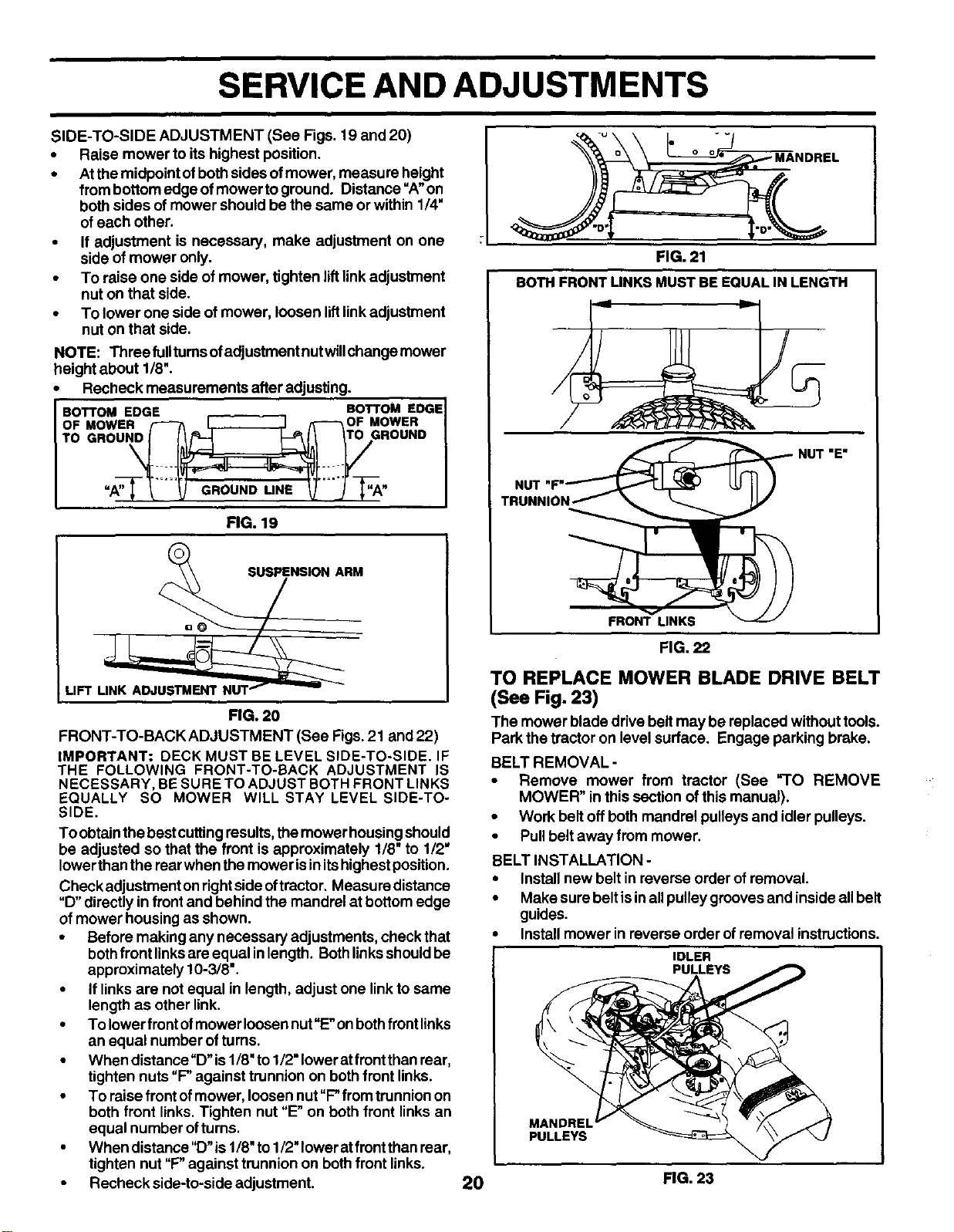
FRONT-TO-BACK ADJUSTMENT (See Figs. 21 and 22)
IMPORTANT: DECK MUST BE LEVEL SIDE-TO-SIDE. IF
THE FOLLOWING FRONT-TO-BACK ADJUSTMENT IS
NECESSARY, BE SURE TO ADJUST BOTH FRONT LINKS
EQUALLY SO MOWER WILL STAY LEVEL SIDE-TO-
SIDE.
To obtainthe bestcuttingresults,the mower housingshould
be adjusted so that the front is approximately 1/8" to 112"
lowerthan the rear when the mower isinitshighestposition.
Check adjustment on rightside oftractor, Measure distance
"D" directly in front and behind the mandrel at bottom edge
of mower housing as shown.
•Before making any necessary adjustments, check that
both front linksare equal inlength. Bothlinksshouldbe
approximately t 0-3/8".
•If linksare not equal in length, adjust one linkto same
length as other link.
•To lowerfront ofmower Ioosannut"E"onbeth front links
an equal number ofturns.
•When distance"D" is1/8' to1/2" Iowerat front than rear,
tighten nuts "P against trunnion on both front links.
•To raise front ofmower, loosen nut"P from trunnionon
both front links. Tighten nut "E" on both front linksan
equal number ofturns.
•When distance "D" is1/8"to 1/2"lowerat front than rear,
tighten nut "P against trunnion on bothfront links.
•Recheck side-to-side adjustment.
FIG. 21
BOTH FRONT LINKS MUST BE EQUAL IN LENGTH
TRUNNION
FRONT UNKS
FIG. 22
TO REPLACE MOWER BLADE DRIVE BELT
(See Fig. 23)
The mower blade drive belt may be replaced without tools.
Park the tractor on level surface. Engage parking brake.
BELT REMOVAL -
•Remove mower from tractor (See "TO REMOVE
MOWER" in this section of this manual).
•Work belt off both mandrel pulleys and idler pulleys,
•Pullbelt away from mower.
BELT INSTALLATION -
•Install new belt in reverse order of removal.
•Make sure belt isinall pulley grooves and inside all belt
guides.
Install mower in reverse order of removal instructions,
IDLER
PULLEYS
PULLEYS
20 FIG. 23
iSERVICE AND ADJUSTMENTS
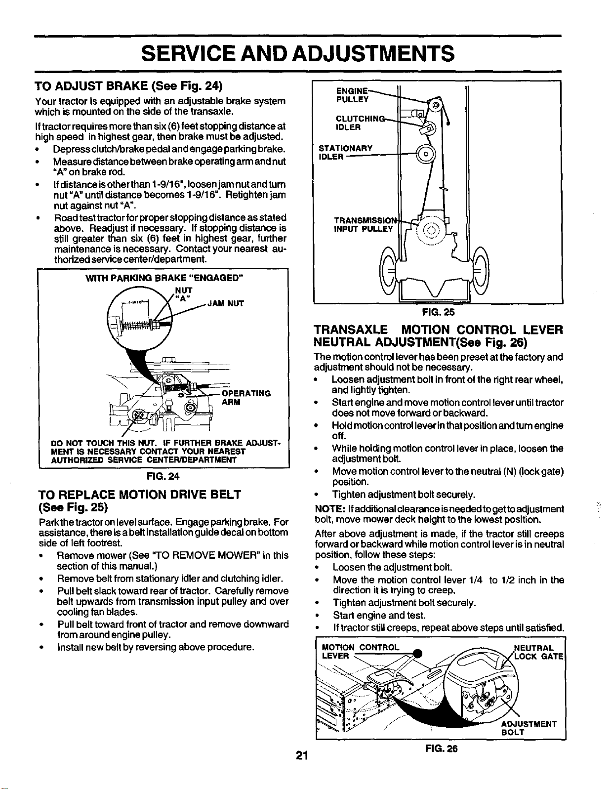
TO ADJUST BRAKE (See Fig. 24)
Your tractor is equipped with an adjustable brake system
which is mounted on the side of the transaxle.
Iftractor requiresmore than six (6) feet stopping distance at
highspeed in highest gear, then brake must be adjusted.
•Depress clutch/brake pedal and engage parking brake.
•Measure distancebetween brake operating armand nut
"A" on brake rod.
•Ifdistanceis otherthan 1-9/16", loosenjam nut and turn
nut =A"untildistance becomes 1-9/16". Retighten jam
nut against nut "A".
•Road testtractorfor properstopping distance as stated
above. Readjust ifnecessary. Ifstopping distance is
still greater than six (6) feet in highest gear, further
maintenance is necessary. Contact your nearest au-
thorized servicecenter/department.
WITH PARKING BRAKE "ENGAGED"
NUT
NUT
ARM
DO NOT TOUCH THIS NUT. IF FURTHER BRAKE ADJUST-
MENT |S NECESSARY CONTACT YOUR NEAREST
AUTHORIZED SERVICE CENTER/DEPARTMENT
FIG. 24
TO REPLACE MOTION DRIVE BELT
(See Fig. 25)
Parkthe tractoron levelsurface. Engage parkingbrake. For
assistance, there isa belt installationguide decal on bottom
side of left footrest.
• Remove mower (See "TO REMOVE MOWER" in this
section ofthis manual.)
• Remove belt from stationary idler and clutching idler.
•Pull belt slacktoward rear oftractor. Carefully remove
belt upwards from transmission input pulley and over
cooling fan blades.
•Pull belt toward front oftractor and remove downward
from around engine pulley.
•install new belt by reversing above procedure.
ENGINE_
PULLEY
CLUTCHING--
IDLER
STATIONARY
IDLER --
TRANSMISSION
INPUT PULLEY
0FIG. 25 0
TRANSAXLE MOTION CONTROL LEVER
NEUTRAL ADJUSTMENT(See Fig. 26)
The motion controllever has been preset at thefactory and
adjustment should notbe necessary.
•Loosen adjustment boltin front ofthe right rear wheel,
and lightlytighten.
•Startengine and move motioncontrollever untiltractor
does not moveforward or backward.
• Hold motioncontrollever inthatpositionand turnengine
off.
•While holdingmotion control lever in place, loosen the
adjustment bolt.
•Move motioncontrollever tothe neutral (N) (lock gate)
position.
•Tighten adjustment boltsecurely.
NOTE: Ifadditionalciearance isneededtoget toadjustment
bolt, move mower deck height to the lowest position.
After above adjustment is made, if the tractor stillcreeps
forward or backward while motion controllever isin neutral
position, follow these steps:
•Loosen the adjustment bolt.
• Move the motion control lever 1/4 to 1/2 inch in the
direction it is trying to creep.
• Tighten adjustment bolt securely.
•Start engine and test.
•Iftractor stillcreeps, repeat above steps untilsatisfied.
MOTION CONTROL NEUTRAL
LEVER GATE
......... kDJUSTMENT
'BOLT
FIG. 26
21
SERVICE AND ADJUSTMENTS
TRANSMISSION REMOVAL/REPLACEMENT
Should your transmission require removal for service or
replacement, it should be purged after reinstallation and
before operating the tractor. See "PURGE TRANSMIS-
SION" inthe Operation section ofthis manual.
TO ADJUST STEERING WHEEL ALIGNMENT
If steering wheel crossbars are not horizontal (left to right)
when wheels are positionedstraightforward, remove steer-
ingwheel and reassemble per instructionsin theAssembly
section of this manual.
FRONT WHEEL TOE-IN/CAMBER
The frontwheel toe-inand camber are notadjustableonyour
tractor. Ifdamage hasoccurred toaffectthefront wheel toe-
in or camber, contact your nearest authorized service
center/department.
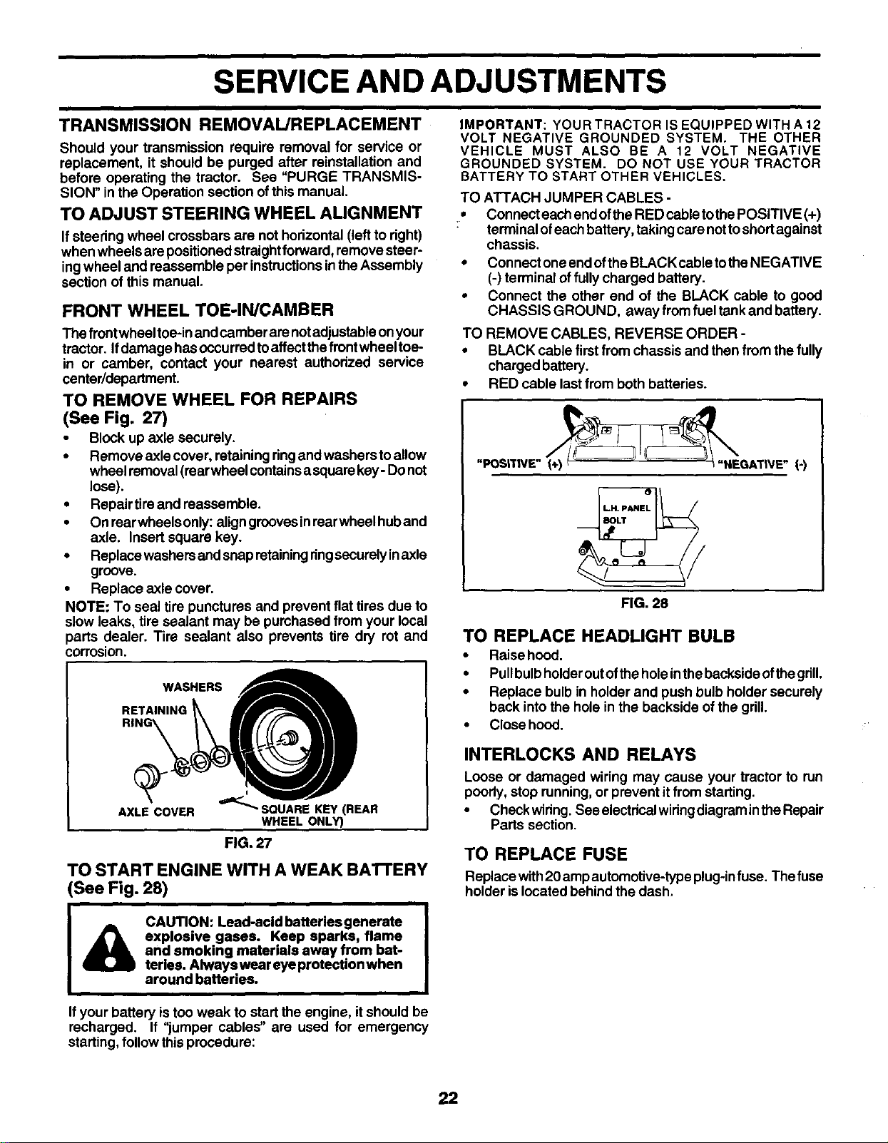
TO REMOVE WHEEL FOR REPAIRS
(See Fig. 27)
•Block up axle securely.
•Remove axle cover, retaining ringand washersto allow
wheel removal(rearwheel containsa squarekey -Do not
lose).
•Repair tire and reassemble.
•Onrearwheelsonly: aligngroovesinrearwheelhuband
axle. Insert square key.
•Replace washers and snap retainingringsecurelyinaxle
groove.
•Replace axle cover.
NOTE: To seal tire punctures and prevent flat tires due to
slow leaks, tire sealant may be purchased from your local
parts dealer. Tire sealant also prevents tire dry rot and
corrosion.
WASHERS
RET.,.,HQ
AXLE COVER _=_'_SQUARE KEY(REAR
WHEEL ONLY)
FIG. 27
TO START ENGINE WITH A WEAK BAI-rERY
(See Fig. 28)
IMPORTANT:YOURTRACTORISEQUIPPEDWITHA12
VOLT NEGATIVE GROUNDED SYSTEM. THE OTHER
VEHICLE MUST ALSO BE A12 VOLT NEGATIVE
GROUNDED SYSTEM. DO NOT USE YOUR TRACTOR
BATTERY TO START OTHER VEHICLES.
TO ATTACH JUMPER CABLES -
, Connect each end ofthe RED cable tothe POSITIVE (+)
: terminal ofeach battery, takingcare nottoshortagainst
chassis.
•Connect one end ofthe BLACKcable tothe NEGATIVE
(-) terminal offully charged battery.
•Connect the other end of the BLACK cable to good
CHASSIS GROUND, away from fuel tankand battery.
TO REMOVE CABLES, REVERSE ORDER -
• BLACK cable firstfrom chassis and then from the fully
charged battery.
•RED cable last from both batteries.
"POS|T|VE" _GAT|VE" (-)
FIG. 28
TO REPLACE HEADLIGHT BULB
•Raise heed.
•Pullbulbholderoutofthe holeinthe backsideofthe gdU.
•Replace bulb in holder and push bulb holder securely
back intothe hole in the backside of the grill.
•Close hood.
INTERLOCKS AND RELAYS
Loose or damaged wiring may cause your tractor to run
poorly, stop running, or prevent itfrom starting.
•Check wiring. See electricalwidngdiagram inthe Repair
Parts section.
TO REPLACE FUSE
Replace with20 ampautomoUve-typeplug-infuse, The fuse
holder islocated behind the dash.
CAUTION: Lead-acid batteries generate
explosive gases. Keep sparks, flame
and smoking materials away from bat-
teries. Always wear eye protection when
around batteries.
Ifyour battery is too weak to start the engine, it should be
recharged. It "jumper cables" are used for emergency
starting, follow this procedure:
22
SERVICE AND ADJUSTMENTS
TO ADJUST CARBURETOR
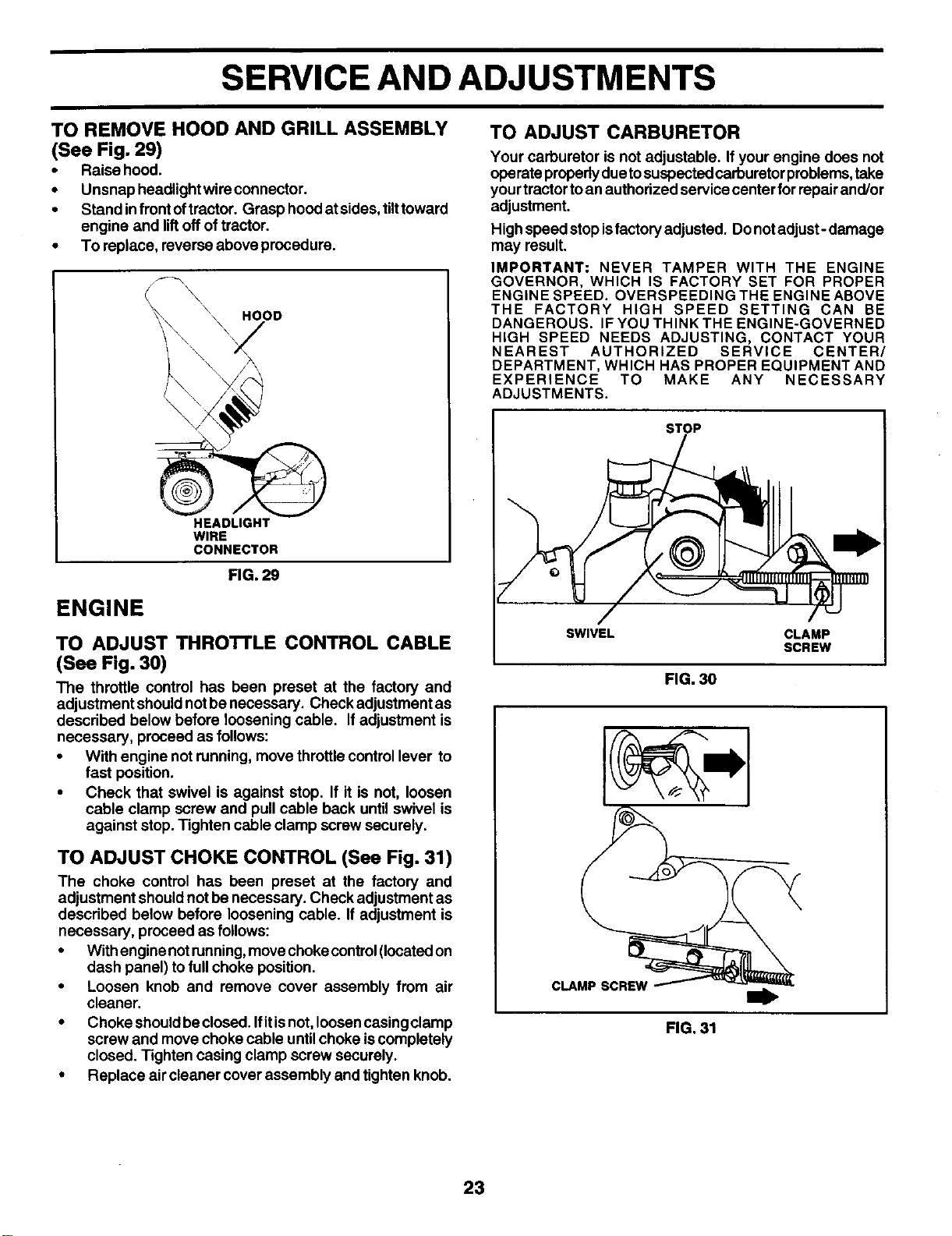
TO REMOVE HOOD AND GRILL ASSEMBLY
(See Fig. 29)
•Raise hood.
•Unsnap headlight wire connector.
•Stand infront oftractor. Grasp hoed at sides,tilttoward
engine and lift offof tractor.
•To replace, reverse above procedure.
\HOOD
HEADLIGHT
WIRE
CONNECTOR
FIG. 29
ENGINE
TO ADJUST THRO'I'rLE CONTROL CABLE
(See Fig. 30)
The throttle control has been preset at the factory and
adjustment shouldnot be necessary. Check adjustment as
described below before loosening cable. If adjustment is
necessary, proceed as follows:
•With engine not running, move throttle controllever to
fast position.
•Check that swivel is against stop. If it is not, loosen
cable clamp screw and pull cable back until swivel is
against stop. Tighten cable clamp screw securely.
TO ADJUST CHOKE CONTROL (See Fig. 31)
The choke control has been preset at the factory and
adjustment shouldnot be necessary. Check adjustment as
described below before loosening cable. If adjustment is
necessary, proceed as follows:
•With engine notrunning,movechoke control(locatedon
dash panel) tofull choke position.
•Loosen knob and remove cover assembly from air
cleaner.
•Choke shouldbeclosed. Ifitisnot, loosencasingclamp
screw and move choke cable untilchoke iscompletely
closed. Tighten casing clamp screw securely.
•Replace air cleaner cover assembly and tighten knob.
Your carburetor is not adjustable. If your engine does not
operate properlydue tosuspectedcarburetorproblems,take
yourtractor toan authorized service center for repairand/or
adjustment.
High speed stop isfactoryadjusted. Do not adjust- damage
may result.
IMPORTANT: NEVER TAMPER WITH THE ENGINE
GOVERNOR, WHICH IS FACTORY SET FOR PROPER
ENGINE SPEED. OVERSPEEDING THE ENGINE ABOVE
THE FACTORY HIGH SPEED SETTING CAN BE
DANGEROUS. IF YOU THINK THE ENGINE-GOVERNED
HIGH SPEED NEEDS ADJUSTING, CONTACT YOUR
NEAREST AUTHORIZED SERVICE CENTER/
DEPARTMENT, WHICH HAS PROPER EQUIPMENT AND
EXPERIENCE TO MAKE ANY NECESSARY
ADJUSTMENTS.
STOP
SWIVEL CLAMP
SCREW
FIG. 30
CLAMP SCREW
FIG.31
23
STORAGE
Immediately prepare yourtractorfor storage atthe endofthe
season or if thetractor willnotbe used for 30 daysor more.
CAUTION: Never store the tractor with
gasoline in the tank Inside a building
where fumes may reach an open flame
or spark. Allow the engine to cool
before storing in any enclosure.
TRACTOR
Remove mower from tractorforwinterstorage. When mower
is to be stored for a period of time, clean it thoroughly,
remove all dirt, grease, leaves, etc. Store in a clean, dry
area.
•Clean entiretractor (See =CLEANING" in theCustomer
Responsibilities section of this manual).
•Inspect and replace belts, if necessary (See belt re-
placement instructions in the Service and Adjustments
section of this manual).
•Lubricate as shown in the Customer Responsibilities
section of this manual.
•Be sure that all nuts, bolts and screws are securely
fastened. Inspect moving parts for damage, breakage
and wear. Replace if necessary.
•Touch up all rusted or chipped paint surfaces; sand
lightlybefore painting.
BATTERY
•Fully charge the battery for storage.
•After a period of time in storage, battery may require
recharging.
•To halppreventcorrosionand powerleakage duringlong
periods of storage, battery cables should be discon-
nected and batterycleaned thoroughly (see 'TO CLEAN
BAI-I'ERY AND TERMINALS" intheCustomer Respon-
sibilities section of this manual).
•After cleaning, leave cables disconnected and place
cables where they cannot come incontact with battery
terminals.
•If battery is removed from tractor for storage, do not
store battery directly on concrete or damp surfaces,
ENGINE
FUEL SYSTEM
IMPORTANT: IT IS IMPORTANT TO PREVENT GUM
DEPOSITS FROM FORMING IN ESSENTIAL FUEL SYSTEM
PARTS SUCH AS CARBURETOR, FUEL FILTER, FUEL
HOSE, OR TANK DURING STORAGE. ALSO,
EXPERIENCE INDICATES THAT ALCOHOL BLENDED
FUELS (CALLED GASOHOL OR USING ETHANOL OR
METHANOL) CAN ATTRACT MOISTURE WHICH LEADS
TO SEPARATION AND FORMATION OF ACIDS DURING
STORAGE. ACIDIC GAS CAN DAMAGE THE FUEL
SYSTEM OF AN ENGINE WHILE iN STORAGE.
•Drain the fuel tank.
•Start the engine and let it run until the fuel lines and
carburetor are empty.
•Never usa engine or carburetor cleaner products in the
fuel tank or permanent damage may occur.
•Use fresh fuel next season.
NOTE: Fuel stabilizer is an acceptable alternative in
minimizing the formation offuel gum deposits during stor-
age. Add stabilizer to gasoline in fuel tank or storage
container. Always follow the mix ratio found on stabilizer
container. Run engine at least 10 minutes after adding
stabilizer to allowthe stabilizer to reach the carburetor. Do
not drain the gastank and carburetor ifusingfuel stabilizer.
ENGINE OIL
Drainoil(withengine warm)and replacewithclean engineoil.
(See =ENGINE" inthe Customer Responsibilities section of
this manual).
CYLINDER(S)
•Remove spark plug(s).
•Pour one ounce of oil through spark plug hole(s) into
cylinder(s).
•Turn ignitionkey to=START" positionfora few seconds
to distdbuteoil.
•Replace with new spark plug(s).
OTHER
•Do not store gasoline from one season to another.
•Replace your gasoline can if your can starts to rust.
Rust and/or dirt inyour gasoline willcause problems.
•Ifpossible,storeyourtractorindoorsand cover ittogive
protectionfrom dust and dirt.
•Cover your tractorwith a suitable protective cover that
does not retain moisture. Do not use plastic. Plastic
cannot breathe which allowscondensation toformand
willcause your tractor to rust.
IMPORTANT: NEVER COVER TRACTOR WHILE ENGINE
AND EXHAUST AREAS ARE STILL WARM.
24
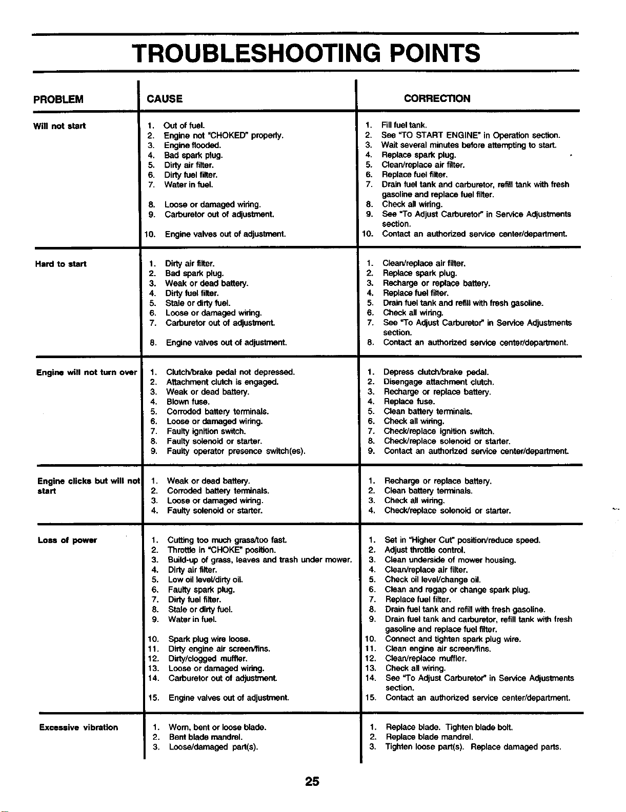
TROUBLESHOOTING POINTS
PROBLEM
Will not start
Hard to start
Engine will not turn over
Engine clicks but will no1
start
Loss of power
Excessive vibration
CAUSE
t. Out of fuel.
2. Engine not =CHOKED" properly.
3. Engine flooded.
4. Bad spark plug.
5. Dirty air filter.
6. Dirty fuel filter.
7, Water in fuel.
8. Looseor damagedwiring.
9. Carburetoroutof adjustmenL
10. Engine valves out of adjusl_,ent.
1. Dirty air filter.
2. Bad spark plug.
3. Weak or dead battery.
4. Dirty fuel filter.
5. Stale or dirty fuel.
6, Loose or damaged widng,
7. Carburetor out of adlustrnanL
8. Enginevanes outof adjustment.
1. Clutch/brake pedal nut depressed.
2. Attachment clutch is engaged.
3, Weak or dead battery.
4. Blown fuse.
5. Corroded battery terminals.
6. Loose or damaged wiring.
7. Faulty ignition switch.
8. Faulty solenoid or starter.
9. Faulty operator presence switch(es),
1. Weak or dead battery.
2. Corrodedbattery terminals.
3. Looseor damaged widng.
4. Faultysolenoidor starter.
1. Cutting too much grass/too fast.
2. Throttle in =CHOKE" position.
3. Build-up of grass, leaves and trash under mower,
4. Dirty air filter.
5, Low oil level/dirty oil,
6, Faulty spark plug.
7. Dirty fuel filter.
8. Stale or dirty fuel.
9. Water in fuel.
10, Spark plug wire loose.
11. Dirty engine air screerv_ns.
12. Dirty/clogged muffler.
13. Loose or damaged widng.
14. Carburetor out of adjustmenL
15, Engine valves out of adjustment.
1. Wom, bent or loose blade.
2. Bent blade mandrel.
3. Loose/damagad part(s).
CORRECTION
1. Fill fuel tank.
2. See "TO START ENGINE" in Operation section.
3. Wait several minutes before attempting to start.
4. Replace spark plug,
5. Clean/replace air filter.
6. Replace fuel filter.
7. Drain fuel tank and carburetor, refill tank with fresh
gasoline and replace fuel filter.
8. Check all widng.
9. See "To Adjust Carburetor" in Service Adjustments
section,
10. Contact an authorized service center/departmeut.
1. Clean/replace air filter.
2. Replace spark plug.
3. Recharge or replace battery.
4. Replace fuel filter.
5, Drain fuel tank and refill with fresh gasoline.
6. Check all widng,
7. See "To Adjust Carburetor" in Service Adjus_nents
section.
8. Contact an authorized service centar/department.
1. Depress clutch/brake pedal.
2. Disengage attachment clutch,
3. Recharge or replace battery.
4, Replace fuse.
5. Clean battery terminals.
6. Check all wiring.
7. Check/replace ignition switch.
8. Chesk/replase solenoid or starter.
g. Contact an authorized service center/dedartment.
1. Recharge or replace battery.
2. Clean battery terrrdnals.
3. Check all widng.
4, Check/replace solenoid or starter.
1. Set in "Higher Cut" posifion/reduce speed,
2. Adjust throttle control,
3. Clean underside of mower housing.
4. Clean/replace air filter.
5. Check oil level/change oil.
6. Clean and regap or change spark plug.
7. Replace fuel filter.
8, Drain fuel tank and refill with fresh gasoline.
9, Drain fuel tank and carburetor, refill tank with fresh
gasoline and replace fuel filter,
10. Connect and tighten spark plug wire,
11. Clean engine air screen/fins.
12. Clean/replace muffler.
13, Check all winng,
14, See "To Adjust Carburetor" in Service Adjustments
section.
15. Contact an authorized service center/department.
1. Replace blade. Tighten blade bolt.
2. Replace blade mandrel.
3. Tighten loose part(s). Replace damaged parts,
25
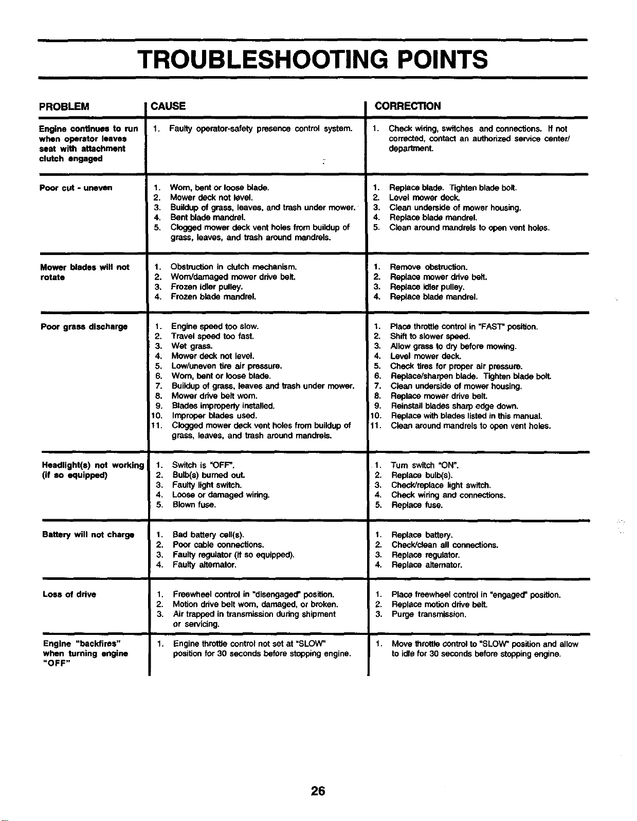
TROUBLESHOOTING POINTS
PROBLEM
Engine continues to run
when operator leaves
seat with attachment
clutch engaged
Poor cut - unevelrl
Mower blades will not
rotate
Poor grass discharge
Headlight(s) not working
(if so equipped)
Battery will not charge
Loss of drive
Engine "backfires"
when turning engine
"OFF"
CAUSE
1. Faulty operator-safetypresence control system.
1. Wom, bent or loose blade.
2. Mower deck not level,
3. Buildup of grass, leaves, and trash under mower.
4. Bent blade mandrel.
5. Clogged mower deck vent holes from buildup of
grass, leaves, and trash around mandrels.
1. Obstruction in clutch mechanism.
2. Worn/damaged mower drive belt.
3. Frozen idler pulley.
4. Frozen blade mandrel.
1. Engine speed too slow.
2, Travel speed too fast.
3. Wet grass.
4, Mower deck not level.
5. Low/uneven tire air pressure.
6. Worn, bent or loose blade,
7. Buildup of grass, leaves and trash under mower.
8. Mower drive belt worn.
9. Blades impmperiy installed.
10. Improper blades used.
11. Clogged mower deck vent holes from buildup of
grass, leaves, and trash around mandrels.
1. Switch is _OFF".
2. Bulb(s) burned out.
3. Faulty light switch.
4. Loose or damaged wiring.
5. Blown fuse.
t. Bad batterycell(s).
2. Poor cable connections.
3. Faultyregulator(if so equipped).
4. Faultyalternator.
1. Freewheel control in =disengaged' position,
2. Motion drive belt wom, damaged, or broken.
3. Air trapped in transmission dunng shipment
or sewicing.
Engine throttle control not set at _SLOW"
position for 30 seconds before stopping engine.
CORRECTION
1. Checkwiring,switches and connections, if not
corrected,contactan authorizedservicecenter/
department.
1. Replaceblade. Tightenbladebolt.
2, Level mowerdeck.
3. Clean undemldeof mowerhousing.
4. Replaceblade mandrel.
5. Clean aroundmandrelsto open vent holes.
1. Remove obstruction.
2. Replacemowerdrivebelt.
3. Replaceidlerpulley.
4. Replaceblademandrel.
I, Place throttle control in =FAST" position.
2, Shift to slower speed.
3. Allow grass to dry before mowing.
4. Level mower deck.
5. Check tires for proper air pressure.
6. Replace/sharpen blade. Tighten blade belt.
7. Clean underside of mower housing.
8, Replace mower drive belt.
9. Reinstall blades sharp edge dawn,
10. Replace with blades listed in this manual.
11, Clean around mandrels to open vent holes.
1. Turn switch _ON'.
2. Replace bulb(s),
3. Check/replace light switch,
4. Check wiring and connections.
5. Replace fuse.
t. Replace battery.
2. Check/clean all connections.
3. Replace regulator.
4. Replace aifemator.
1. Place freewheel contml in =engaged' position.
2. Replace motion drive belt.
3. Purge transmission.
1, Move throttle control to "SLOW* position and allow
to idle for 30 seconds before stopping engine.
26
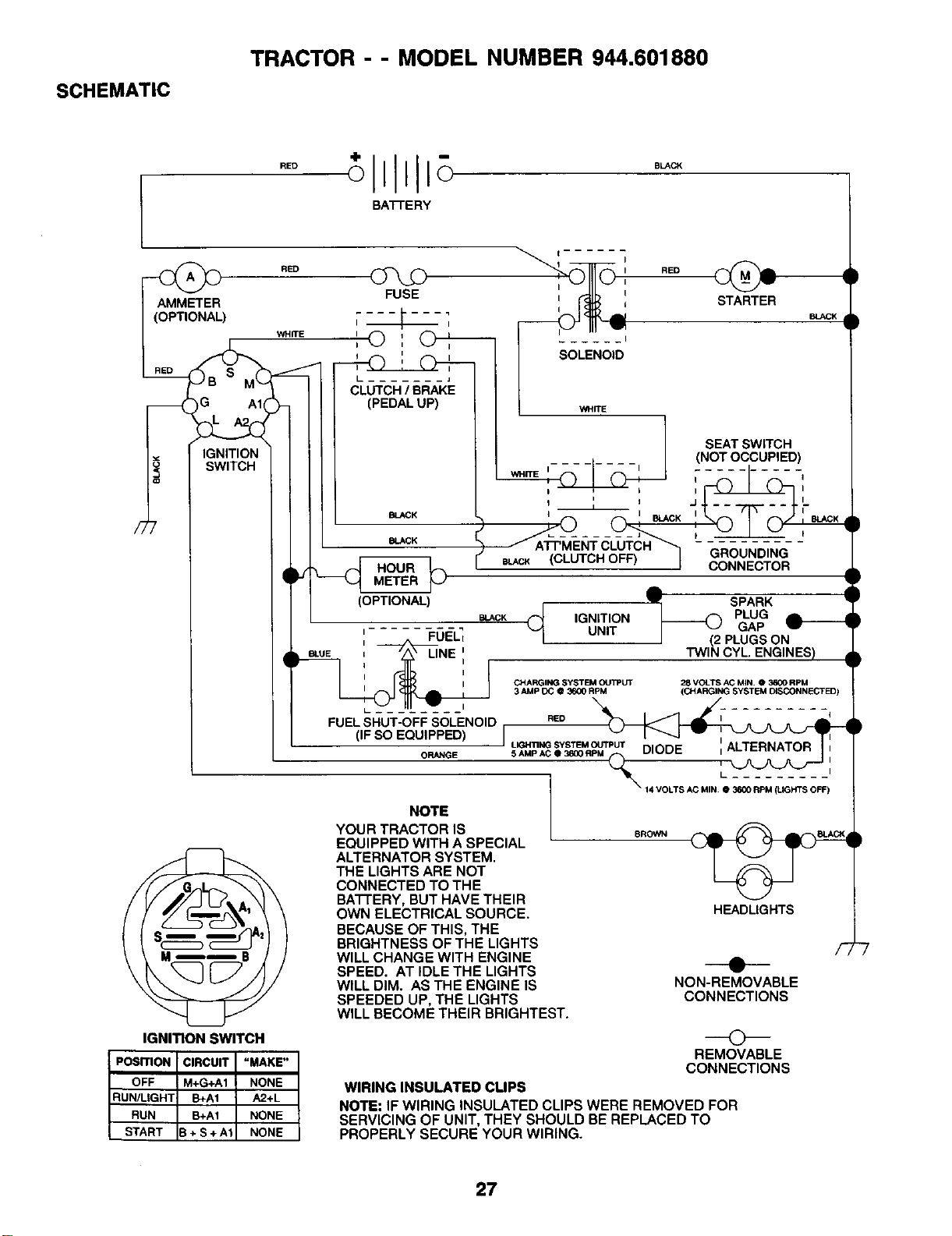
SCHEMATIC
TRACTOR --MODEL NUMBER 944.601880
BATFERY
R_
__G
IGNITION
SWITCH
• =u_ :---/_Z_NE',
I I
FUELSHUT-OFF SOLENOID
(IF SO EQUIPPED)
ORANGE
CHARGING SYSTB_40UI_UT
3 AMP DC O 3600 RPM 28 VOLTS AC M_N. O3600 RPM
(CHARGING SYSTEM DISCONNECTED)
RED
ILIGHI1NGSYSTEMOUT]PUTDIODE : ALTERNATOR
5 AMp AC O3600 RPM =
(_14 VOLTS AC MIN.O 3600 RPM (LIGHTS OFF)
I
IGNITION SWITCH
POSITION CIRCUIT "MAKE"
OFF M+G+A1 NONE
RUN/LIGHT B+A1 A2+L
RUN B+A1 NONE
START B+ S + A1 NONE
NOTE
YOUR TRACTOR IS
EQUIPPED WITH A SPECIAL
ALTERNATOR SYSTEM.
THE LIGHTS ARE NOT
CONNECTED TO THE
BATFERY, BUT HAVE THEIR
OWN ELECTRICAL SOURCE.
BECAUSE OF THIS, THE
BRIGHTNESS OF THE LIGHTS
WILL CHANGE WITH ENGINE
SPEED. AT IDLE THE LIGHTS
WILL DIM. AS THE ENGINE IS
SPEEDED UP, THE LIGHTS
WILL BECOME THEIR BRIGHTEST.
SROWN
HEADLIGHTS
NON-REMOVABLE
CONNECTIONS
©
REMOVABLE
CONNECTIONS
WIRING INSULATED CLIPS
NOTE: IF WIRING INSULATED CLIPS WERE REMOVED FOR
SERVICING OF UNIT, THEY SHOULD BE REPLACED TO
PROPERLY SECURE YOUR WIRING.
27
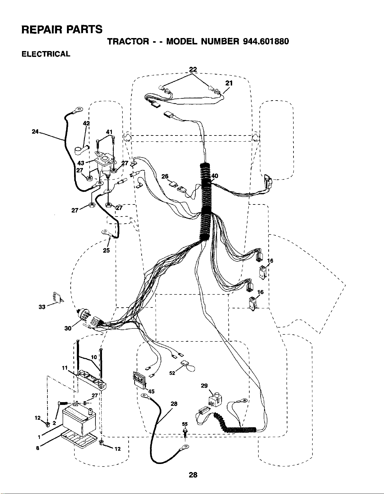
REPAIR PARTS TRACTOR -- MODEL NUMBER 944.601880
ELECTRICAL
I
J
I
42 41
\I
2i
/
I
I
I
I
/
l
I
22
26
-- I
I
I
I
I
I
I
16 ".
I
I
i
16 i
\
\
I
I
I
I
\
"2
I
I
I
/
/
/
I
ii
/
I
I
I
I
I
I
I
28
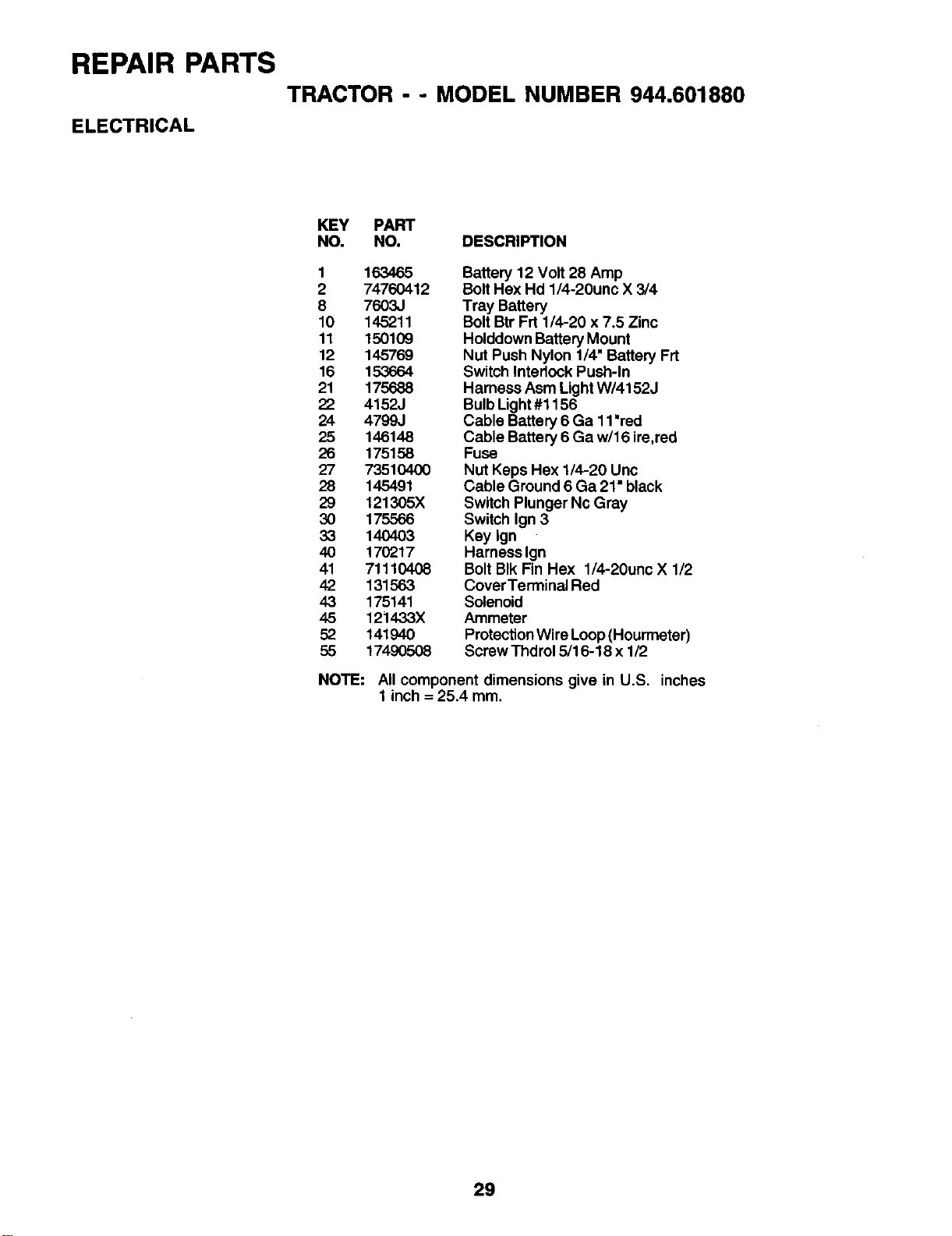
REPAIR PARTS TRACTOR - - MODEL NUMBER 944.601880
ELECTRICAL
KEY PART
NO. NO. DESCRIPTION
1 163465
2 74760412
8 7603.1
10 145211
11 150109
12 145769
16 153664
21 175688
22 4152J
24 4799J
25 146148
26 175158
27 73510400
28 145491
29 121305X
30 175566
33 140403
40 170217
41 71110408
42 131563
43 175141
45 121433X
52 141940
55 17490508
Battery 12 Volt 28 Amp
BoltHex Hd 1/4-20unc X 3/4
Tray Battery
Bolt Btr Frt 1/4-20 x 7.5 Zinc
Holddown Battery Mount
Nut Push Nylon 1/4" Battery Frt
Switch Interlock Push-In
Harness Asm Light W/4152J
Bulb Light#1156
Cable Battery 6 Ga 11'red
Cable Battery 6 Ga w/16 ire,red
Fuse
Nut Keps Hex 1/4-20 Unc
Cable Ground 6 Ga 21 •black
Switch Plunger Nc Gray
Switch Ign 3
Key Ign
Harness Ign
Bolt BIk Fin Hex 1/4-20unc X 1/2
CoverTerminal Red
Solenoid
Ammeter
ProtectionWire Loop(Hourrneter)
Screw Thdrol 5/16-18 x 1/2
NOTE: All component dimensions give in U.S. inches
1 inch = 25.4 mm.
29
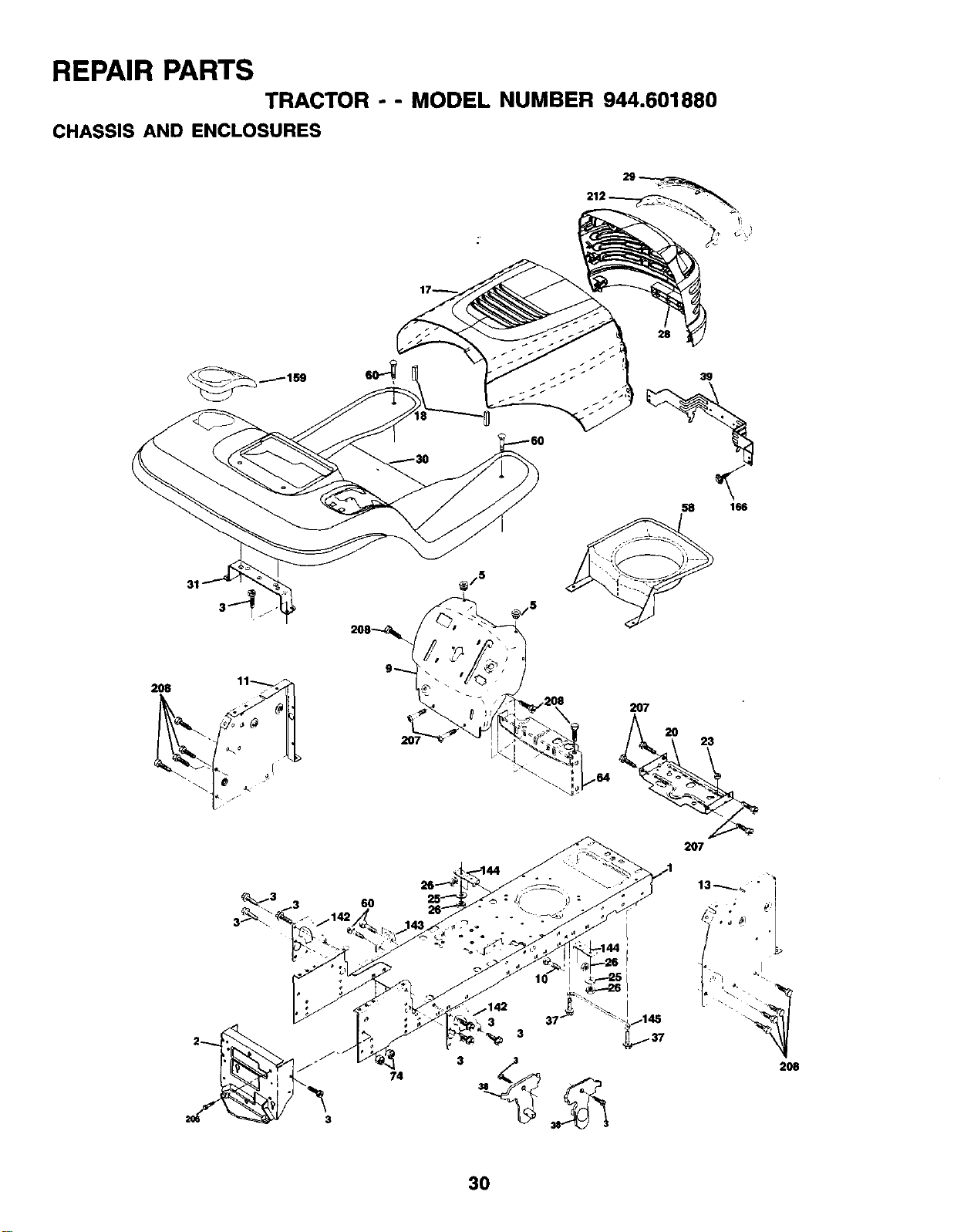
REPAIR PARTS TRACTOR -- MODEL NUMBER 944.601880
CHASSIS AND ENCLOSURES
28
58 166
2O8
6O
74
37
3
2O7
2O7
3O
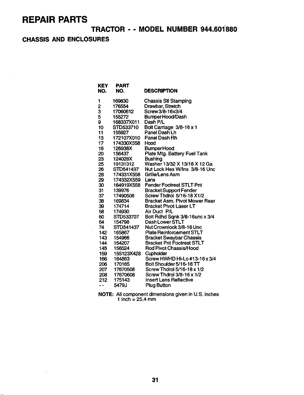
REPAIR PARTS TRACTOR -- MODEL NUMBER 944.601'880
CHASSIS AND ENCLOSURES
KEY PART
NO. NO. DESCRIPTION
1 169830
2 176554
3 17060612
5 155272
9 168337)(011
10 STD533710
11 155927
13 172107X010
17 174330X558
18 126938X
20 1564.37
23 124028X
25 19131312
26 S'1"D541437
28 174331X558
29 174332X559
30 164919X558
31 139976
37 17490508
38 159834
39 174714
58 174930
60 SrD533707
64 154798
74 STD541437
142 165867
143 154966
144 154207
145 156524
159 155123X428
166 164863
206 170165
207 17670508
208 17670608
212 175143
- - 5479J
Chassis Stl Stamping
Drawbar, Stretch
Screw3/8-16x3/4
BumperHood/Dash
Dash P/L
BoltCarriage 3/8-16 x 1
Panel Dash Lh
Panel Dash Rh
Hood
BumperHood
Plate Mtg. Battery Fuel Tank
Bushing
Washer 13/32 X 13/16 X 12 Ga
Nut Lock Hex W/Ins 3/8-16 Uric
Grille/Lens Asm
Lens
Fender Footrest STLT Pnt
Bracket Support Fender
Screw Thdrol 5/16-18 X1/2
Bracket Asm. Pivot Mower Rear
Bracket Pivot Laser LT
Air Duct P/L
Bolt Rdhd Sqnk 3/8-16unc x 3/4
Dash Lower STLT
Nut Cmwnlock 3/8-16 Unc
Plate Reinforcement STLT
Bracket Swaybar Chassis
Bracket Pnt Footrest STLT
Rod Pivot Chassis/Hood
Cupholder
Screw HWHD Hi-Lo #13-16 x 3/4
BoltShoulder 5/16-18 "l-r
Screw Thdrol 5/16-18 x 1/2
Screw Thdrot 3/8-16 x 1/2
Insert Lens Reflective
Plug Button
NOTE: Allcomponent dimensions given in U.S. inches
1 inch = 25.4 mm
31
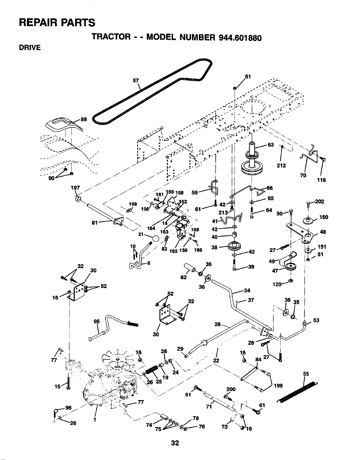
REPAIR PARTS
TRACTOR - - MODEL NUMBER 944.601880
DRIVE
36
61
32
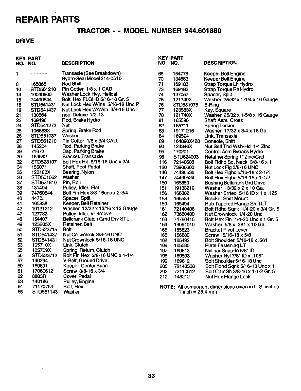
REPAIR PARTS
TRACTOR - - MODEL NUMBER 944.601880
DRIVE
KEY PART KEY PART
NO. NO. DESCRIPTION NO. NO. DESCRIPTION
1 Transaxle (See Breakdown) 66 154778
Hydro Gear Model 314-0510 70 134683
8 165866 Rod Shift 71 169183
10 STD561210 PinCotter 1/8xl CAD 73 169182
14 10040800 Washer Lock Hvy. Helical 74 137057
15 744.90544 Bolt,Hex FLGHD 5/16-18 Gr. 5 75 121749X
16 STD541431 Nut Lock Hex W/Ins 5/16-18 Unc P 76 STD581075
19 STD541437 Nut Lock Hex W/Wsh 3/8-16 Unc 77 123583X
21 130564 nob, Deluxe 1/2-13 78 121748X
22 169498 Rod, Brake Hydro 81 165596
24 STD541273 Nut 82 165711
25 106888X Spdng, Brake Rod 83 19171216
26 STD551037 Washer 84 169594
27 STD561210 Pin Cotter 1/8 x 3/4 CAD. 89 164890X428
28 145204 ROd,Parking Brake 90 124346X
29 71673 Cap, Parking Brake 95 170201
30 169592 Bracket,Transaxle 96 SrD624003
32 STD523107 BoltHex Hd 5/16-18 Uric x 3/4 116 72140608
34 155071 Shaft, Foot Pedal 120 73900600
35 120183X Bearing, Nylon 146 74490536
36 STD551062 Washer 147 74490524
37 STD571816 Pin, Roll 150 165850
38 131494 Pulley, Idler, Flat 151 19133210
39 74760644 Bolt Fin Hex 3/8-16unc x 2-3/4 156 166002
40 4470J Spacer, Split 158 165589
41 165838 Keeper, Belt Retainer 159 165494
42 19131312 Washer 13/32 x 13/16 x 12 Gauge 161 72140406
47 127783 Pulley, Idler, V-Groove 162 73680400
48 154407 Bellcrank Clutch Grad Dry STL 163 74780416
49 123205X Retainer, Belt 164 19091010
50 STD523715 Bolt 165 165623
51 STD541437 NutCrownlock 3/8-16UNC 166 166880
52 STD541431 NutCrownlock 5/16-18UNC 168 165492
53 105710X Link, Clutch 169 165580
55 105709X Spdng, Return, Clutch 197 169613
56 STD523712 Bolt Fin Hex 3/8-16 UNC x1-1/4 198 169593
57 140294 V-Belt, Ground Ddve 199 169612
59 169691 Keeper, Center Span 200 72140508
61 17060612 Screw 3/8-16x3/4 202 72110612
62 8883R Cover, Pedal 212 145212
63 140186 Pulley, Engine
64 71170764 Bolt, Hex
65 SrD551143 Washer
Keeper Belt Engine
Keeper Belt Engine
Strap Torque Lh Hydro
Strap Torque Rh Hydro
Spacer, Split
Washer 25/32 x 1-1/4 x 16 Gauge
E-Ring
Key, Square
Washer 25/32 x 1-5/8 x 16 Gauge
Shaft Asm. Cross
SpdngTorsion
Washer 17/32 x 3/4 x 16 Ga.
Link,Transaxle
Console, Shift
Nut Self Thd Wsh-Hd 1/4 Zinc
Control Asm Bypass Hydro
Retainer Spdng 1"Zinc/Cad
Bolt Rdhd Bq. Neck 3/8-16 x 1
Nut Lock Fig 3/8-16 UNC
Bolt Hex Flghd 5/16-18 x 2-1/4
Bolt Hex Flghd 5/16-18 x 1-1/2
Bushing Bellcrank Grd Drive
Washer 13/32 x 2 x 10 Ga.
Washer Srrted 5/16 ID x 1 x .125
Bracket Shift Mount
Hub Tapered Flange Shift LT
Bolt Rdhd Sqnk 1/4-20 x 3/4 Gr. 5
Nut Crownlock 1/4-20 Unc
Bolt Hex Fin 1/4-20 Uric x 1 Gr. 5
Washer 5/8 x .281 x 10 Ga.
Bracket Pivot Lever
Screw 5/16-18 x 5/8
Bolt Shoulder 5/16-18 x .561
Plate Fastening LT
Nyliner Snap-In 5/8" ID
Washer Nyl 7/8" ID x .105"
Bolt Shoulder 5/16-18 Unc
Bolt Rdhd Sqnk 5/16-18 Unc x 1
Bolt Cart Sh 3/8-16 x 1-1/2 Gr. 5
Nut Hex Flange Lock
NOTE: All component dimensions given in U.S. inches
1 inch = 25.4 mm
33
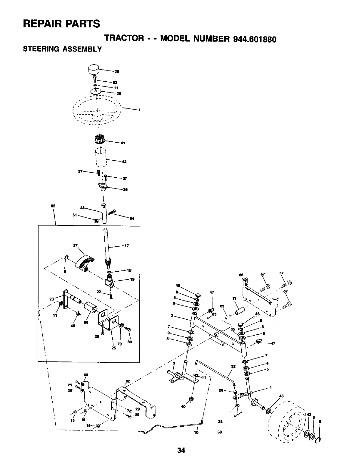
REPAIR PARTS
TRACTOR --MODEL NUMBER 944.601880
STEERING ASSEMBLY
6_Z
r._ i i--------_ 1
_41
27
11
/
117
118
I
40
68
2S
2'g
15 15
68 67 67
8_ 47 -67
6_ 13 _
34
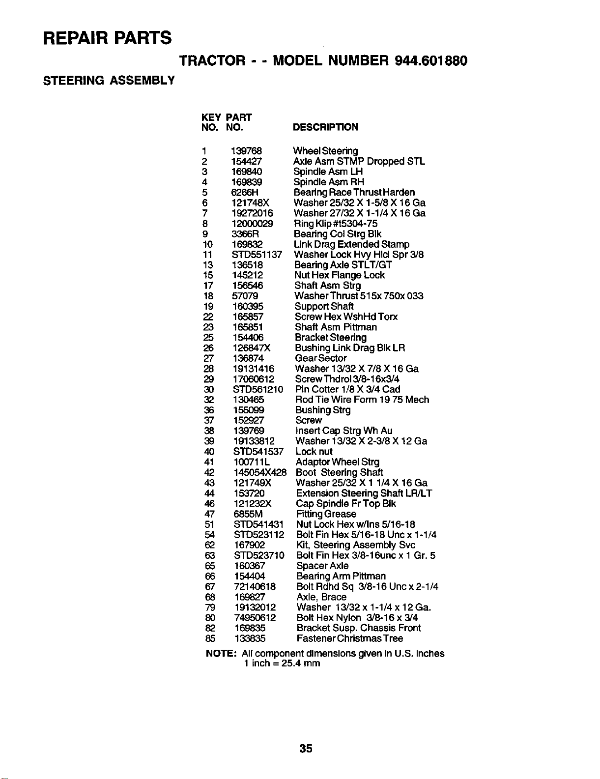
REPAIR PARTS
TRACTOR --MODEL NUMBER 944.601880
STEERING ASSEMBLY
KEY PART
NO. NO. DESCRIPTION
1 139768
2 154427
3 169840
4169839
5 6266H
6 121748X
719272016
812OO0O29
9 3366R
10 1698,.32
11 STD551137
13 136518
15 145212
17 156546
18 57079
19 160395
22 165857
23 165851
25 154406
26 126847X
27 136874
28 19131416
29 17060612
30 STD561210
32 13O465
36 155O99
37 152927
38 139769
39 19133812
40 STD541537
41 100711L
42 145054X428
43 121749X
44 153720
46 121232X
47 6855M
51 STD541431
54 STD523112
62 167902
63 SrD523710
65 160367
66 1544O4
67 72140618
68 169827
79 19132012
80 74950612
82 169835
85 133835
Wheel Steering
Axle Asm STMP Dropped STL
Spindle Asm LH
Spindle Asm RH
Bearing RaceThrust Harden
Washer 25/32 X 1-5/8 X 16 Ga
Washer 27/32 X 1-1/4 X 16 Ga
Ring Klip#t5304-75
Bearing Col Strg BIk
Link Drag Extended Stamp
Washer Lock Hvy HIcl Spr 3/8
Bearing Axle STLT/GT
Nut Hax Flange Lock
Shaft Asm Strg
Washer Thrust 515x 750x 033
Support Shaft
Screw Hex WshHd Torx
Shaft Asm Pittman
Bracket Steering
Bushing Unk Drag BIk LR
GearSector
Washer 13/32 X 7/8 X 16 Ga
Screw Thdrol 3/8-16x3/4
Pin Cotter 1/8 X 3/4 Cad
Rod Tie Wire Form 19 75 Mech
Bushing Strg
Screw
InsertCap Strg Wh Au
Washer 13/32 X 2-3/8 X 12 Ga
Lock nut
Adaptor Wheel Strg
Boot Steering Shaft
Washer 25/32 X 1 1/4 X 16 Ga
Extension Steering Shaft LR/LT
Cap Spindle Fr Top BIk
FittingGrease
Nut Lock Hex w/Ins 5/16-18
Bolt Fin Hex 5/16-18 Uric x 1-1/4
Kit, Steering Assembly Svc
BoltFin Hex 3/8-16unc x 1 Gr. 5
Spacer Axle
Bearing Arm Pittman
BoltRdhd Sq 3/8-16 Unc x 2-1/4
Axle, Brace
Washer 13/32 x 1-1/4 x 12 Ga.
Bolt Hex Nylon 3/8-16 x3/4
Bracket Susp. Chassis Front
Fastener Christmas Tree
NOTE: All component dimensions given in U.S. inches
1 inch = 25.4 mm
35
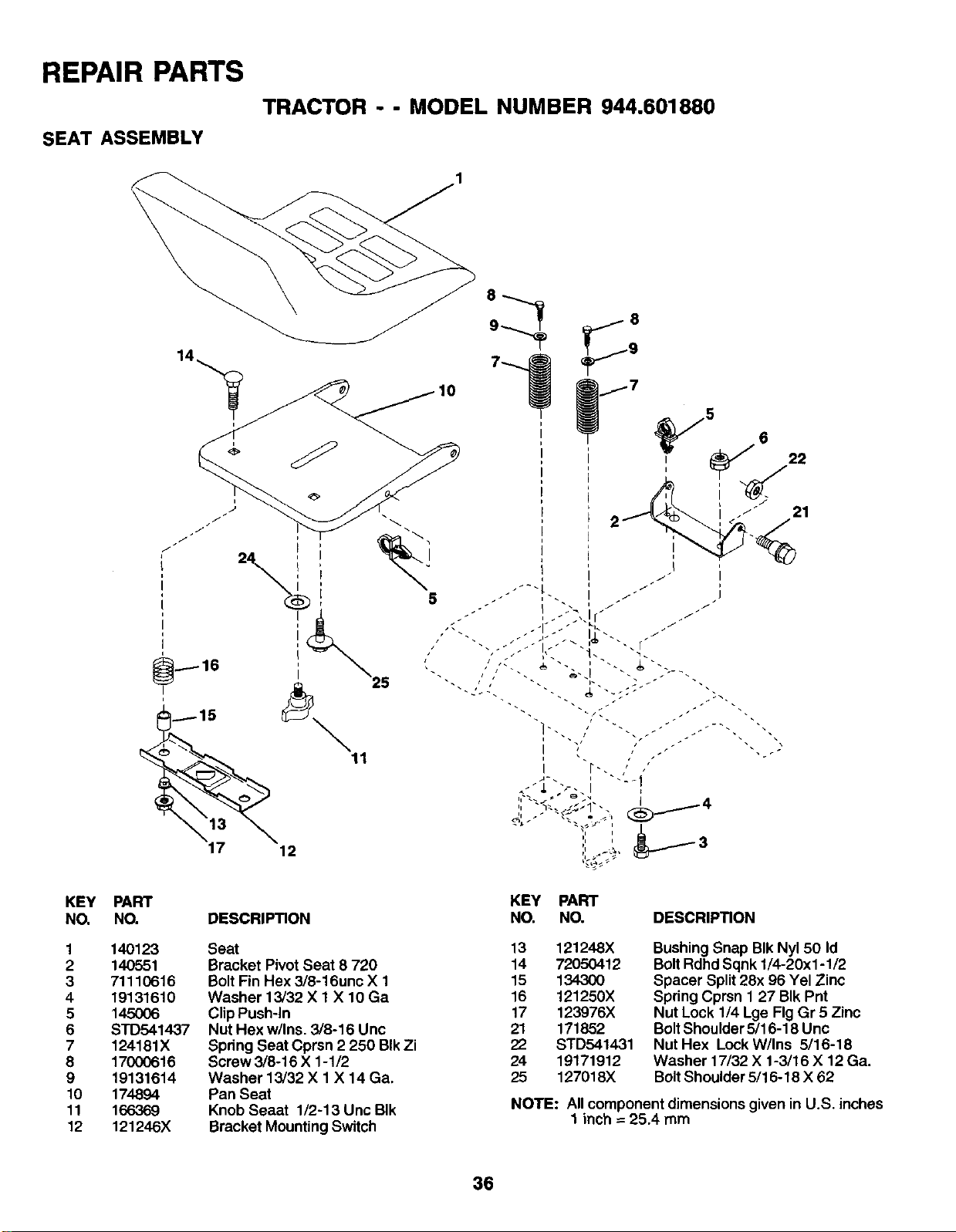
REPAIR PARTS
TRACTOR --MODEL NUMBER 944.601880
SEAT ASSEMBLY
KEY
NO.
1
2
3
4
5
6
7
8
9
10
11
12
25
11
PART
NO.
14O123
140551
71110616
19131610
145OO6
STD541437
124181X
17OO0616
19131614
174894
166369
121246X
DESCRIPTION
Seat
Bracket Pivot Seat 8 720
BoltFin Hex 3/8-16unc X 1
Washer 13/32 X 1 X 10 Ga
Clip Push-In
Nut Hex w/Ins. 3/8-16 Unc
Spdng Seat Cprsn 2 250 BIk Zi
Screw 3/8-16 X 1-1/2
Washer 13/32 X 1 X 14 Ga.
Pan Seat
Knob Seaat 1/2-13 Unc BIk
Bracket MountingSwitch
5
21
KEY PART
NO. NO. DESCRIPTION
13 121248X
14 72050412
15 134300
16 121250X
17 123976X
21 171852
22 STD541431
24 19171912
25 127018X
Bushing Snap BIk Nyl 50 Id
BoltRdhd Sqnk 1/4-20xl -1/2
Spacer Split 28x 96 Yel Zinc
Spdng Cprsn 1 27 BIk Pnt
Nut Lock 1/4 Lge Fig Gr 5Zinc
BoltShoulder 5/16-18 Unc
Nut Hex Lock W/Ins 5/16-18
Washer 17/32 X 1-3/16 X 12 Ga.
BoltShoulder 5/16-18 X 62
NOTE: Allcomponent dimensions given in U.S. inches
1 inch -- 25.4 mm
36
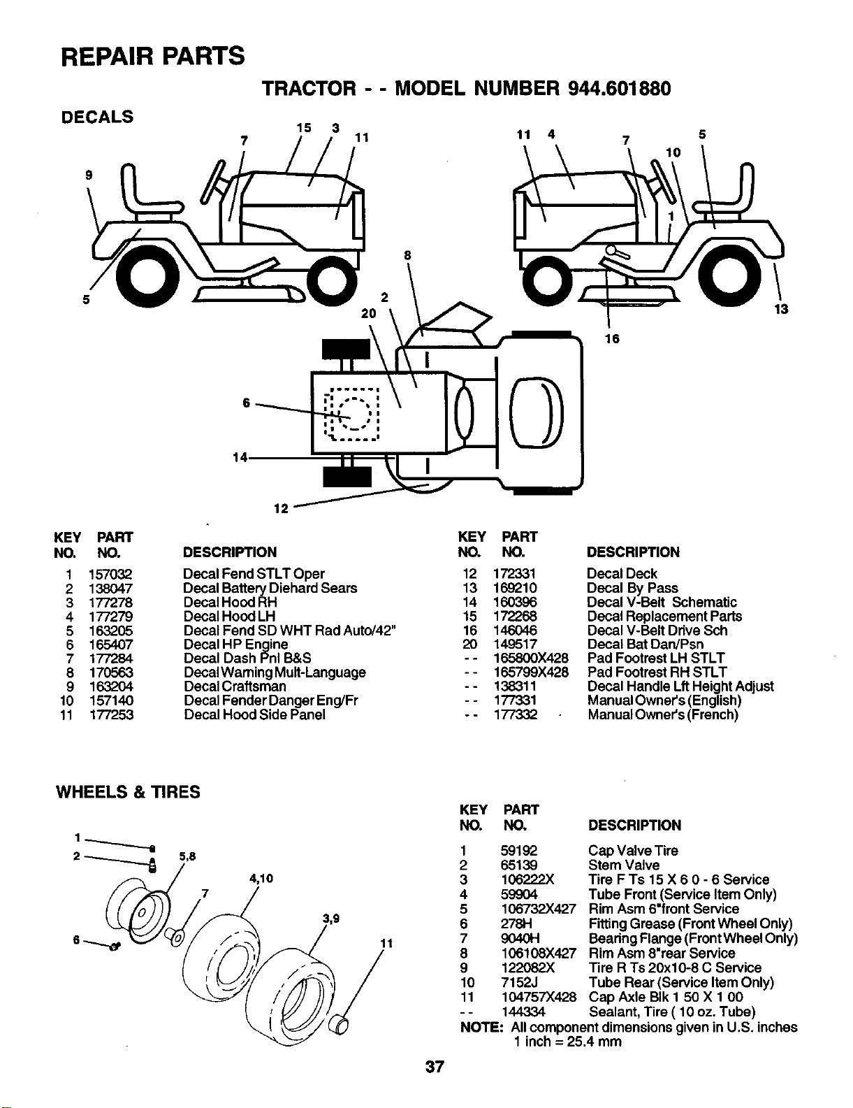
REPAIR PARTS
DECALS
7
9
5
14,
TRACTOR - - MODEL NUMBER 944.601880
15 3 11 11 4 7
2
2O
8
16
5
10
13
KEY PART
NO. NO.
1 157032
2 138047
3177278
4177279
5 163205
6 165407
7177284
8 170563
9 163204
10 157140
11 177253
12
DESCRIPTION
Decal Fend STLT Oper
Decal Battery Diehard Sears
Decal Hood RH
Decal Hood LH
Decal Fend SD WriT ROdAuto/42"
Decal HP Engine
Decal Dash Pnl B&S
Decal Warning Mult-Language
Decal Craftsman
Decal Fender Danger Eng/Fr
Decal Hood Side Panel
KEY PART
NO. NO.
12 172331
13 169210
14 160396
15 172268
16 146046
20 149517
- - 165800X428
- - 165799X428
- - 138311
- - 177331
-- 177332
DESCRIPTION
Decal Deck
Decal By Pass
Decal V-Belt Schematic
Decal Replacement Parts
Decal V-Belt Drive Sch
Decal Bat Dan/Psn
Pad Footrest LH STLT
Pad Footrest RH STLT
Decal Handle LftHeight Adjust
Manual Owner's (English)
Manual Owner's (French)
WHEELS & TIRES
1_._.__._._
2 -_O_,8
/'i
4,10
/
3,9
37
KEY PART
NO. NO, DESCRIPTION
1 59192
265139
3 106222X
4 59904
5106732X427
627811
7 904O14
8106108X427
9 122082X
10 7152J
11 104757)(428
-- 144334
Cap Valve Tire
Stem Valve
Tire F Ts 15 X60-6Service
Tube Front (Service Item Only)
Rim Asm 6"front Service
FittingGrease (Front Wheel Only)
Bearing Flange (Front Wheel Only)
Rim Asm 8"rear Service
Tire R Ts 20x10-8 C Service
Tube Rear (Service Item Only)
Cap Axle BIk 1 50 X 1 00
Sealant, Tire ( 10 oz. Tube)
NOTE: All component dimensions given in U.S. inches
1 inch = 25,4 mm
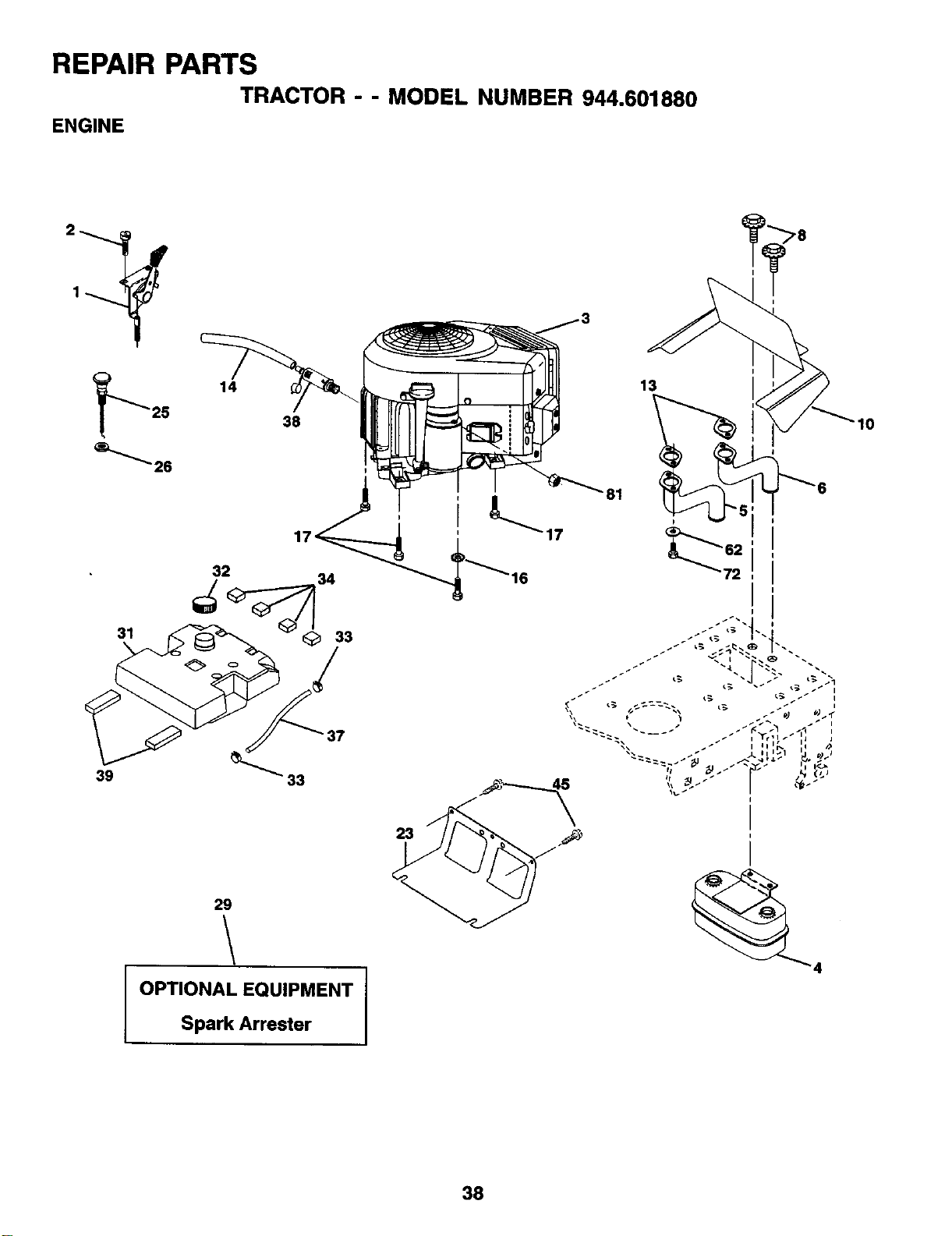
REPAIR PARTS
TRACTOR --MODEL NUMBER 944.601680
ENGINE
2_
1425 38
31
32
37
39 33
29
JOPTIONAL EQUIPMENT
Spark Arrester
23
13
I0
38
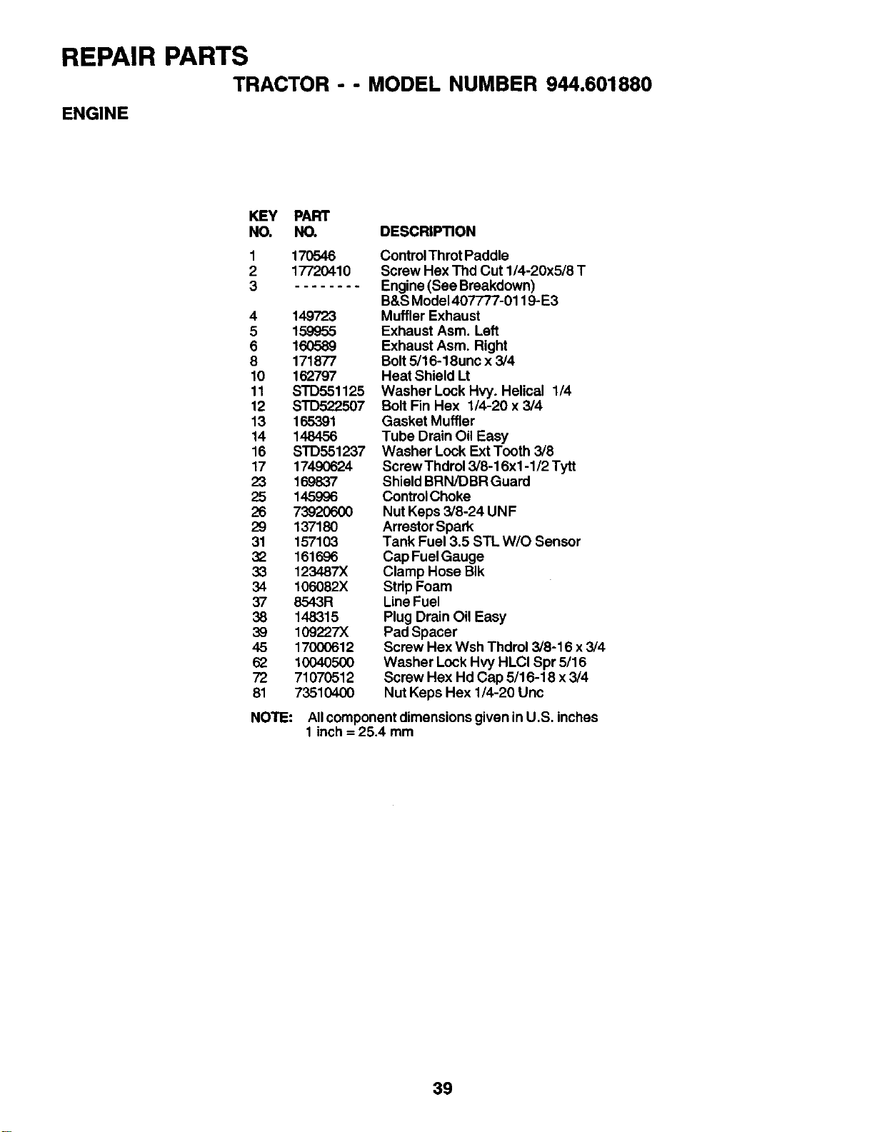
REPAIR PARTS
TRACTOR - -MODEL NUMBER 944,601880
ENGINE
KEY PART
NO. NO. DESCRIPTION
1
2
3
170546
17720410
4 149723
5 159955
6 16O589
8 171877
10 162797
11 STD551125
12 STD522507
13 165391
14 148456
16 STD551237
17 17490624
23 169837
25 145996
26 7392O6OO
29 137180
31 157103
32 161696
33 123487X
34 106082X
37 8543R
38 148315
38 109227X
45 17000612
62 10040500
72 71070512
81 73510400
NOTE:
Control Throt Paddle
Screw Hex Thd Cut 1/4-20x5/8 T
Engine (See Breakdown)
B&S Model407777-0119-E3
Muffler Exhaust
Exhaust Asm. Left
Exhaust Asm. Right
Bolt5/16-18unc x 3/4
Heat Shield Lt
Washer Lock Hvy. Helical 1/4
Bolt Fin Hex 1/4-20 x 3/4
Gasket Muffler
Tube Drain Oil Easy
Washer Lock Ext Tooth 3/8
ScrewThdrol 3/8-16xl -1/2 Tytt
Shield BRN/DBR Guard
ControlChoke
Nut Keps 3/8-24 UNF
Arrestor Spark
Tank Fuel 3.5 STL W/O Sensor
Cap FuelGauge
Clamp Hose BIk
Strip Foam
Line Fuel
Plug Drain Oil Easy
Pad Spacer
Screw Hex Wsh Thdrol 3/8-16 x 3/4
Washer Lock Hvy HLCI Spr 5/16
Screw Hex Hd Cap 5/16-18 x 3/4
Nut Keps Hex 1/4-20 Unc
Allcomponent dimensions given in U.S. inches
1 inch =25.4 mm
39
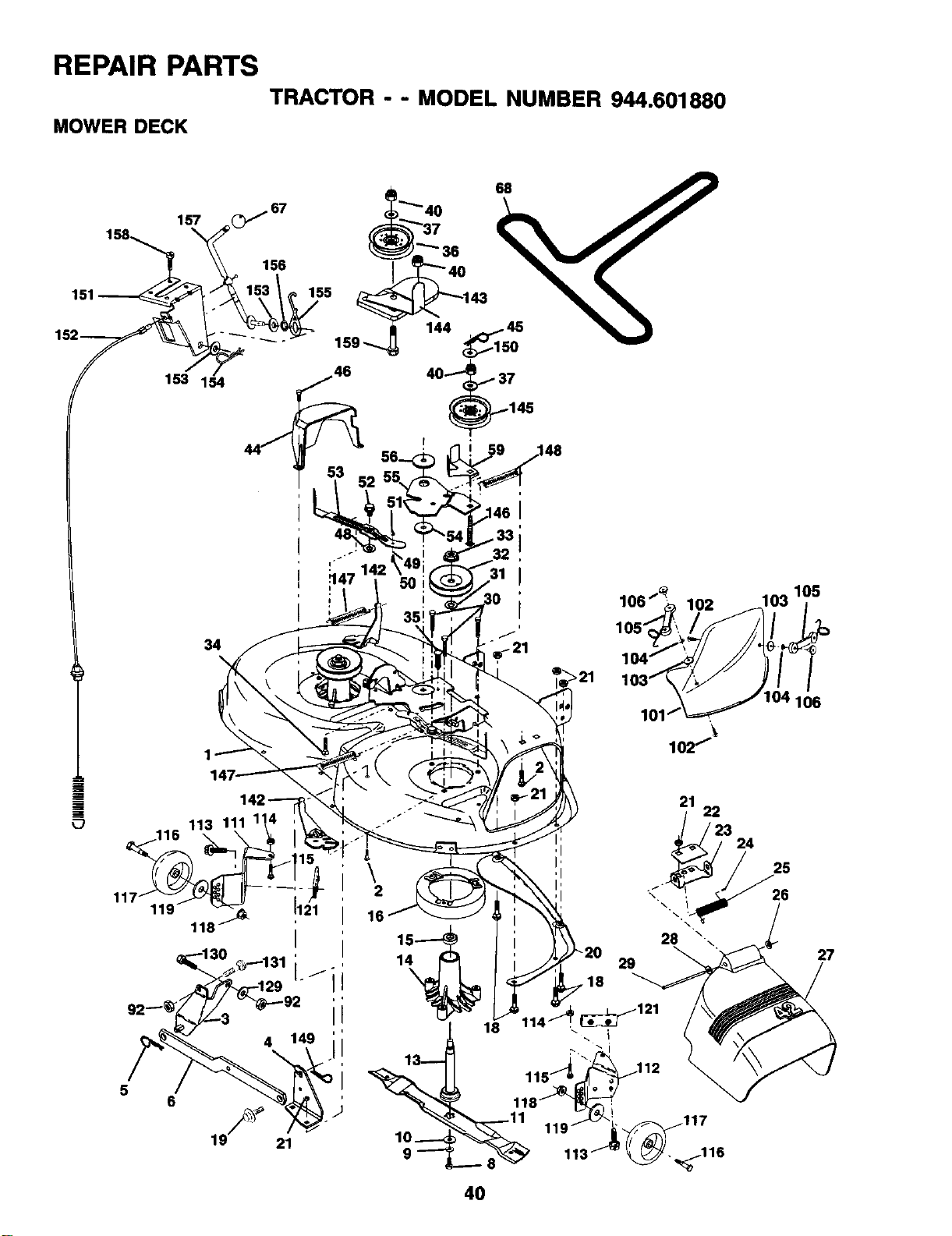
REPAIR PARTS
TRACTOR --MODEL NUMBER 944.601880
MOWER DECK
;146
f.
_47 142
102
lOl
102_
103 105
/
106
|113 111 1!
_.116
119
21
40
22
/23 24
25
26
27
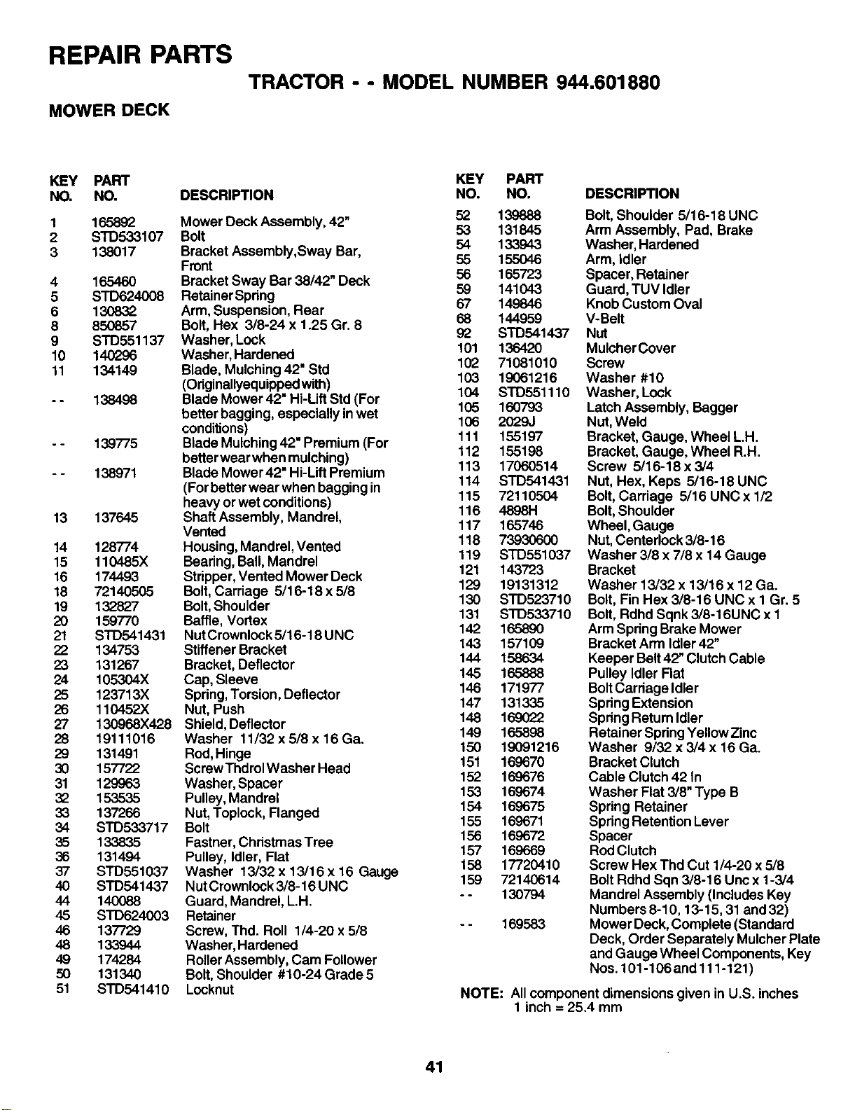
REPAIR PARTS TRACTOR --MODEL NUMBER 944.601880
MOWER DECK
KEY PART KEY PART
NO. NO. DESCRIPTION NO. NO. DESCRIPTION
1
2
3
165892
S'rD533107
138017
416546O
5 STD624008
6130832
8 850857
9 STD551137
10 140296
11 134149
138498
139775
138971
13 137645
14 128774
15 110485X
16 174493
18 72140505
19 132827
20 159770
21 SrD541431
22 134753
23 131267
24 105304X
25 123713)(
26 110452X
27 130968X428
28 19111016
29 131491
30 157722
31 129963
32 153535
33 137266
34 STD533717
35 133835
36 131494
37 S'rD551037
40 STD541437
44 140O88
45 SrD624003
46 137729
48 133944
49 174284
50 131340
51 STD541410
Mower Deck Assembly, 42" 52 139888
53 131845
Bolt 54 133943
Bracket Assembly,Sway Bar,
Front 55 155046
Bracket Sway Bar 38142"Deck 56 165723
59 141043
Retainer Spdng 67 149846
Arm, Suspension, Rear
Bolt, Hex 3/8-24 x 1.25 Gr. 8 68 144959
92 STD541437
Washer, Look 101 136420
Washer, Hardened 102 71081010
Blade, Mulching 42" Std 103 19061216
(Odginallyequippedwith) 104 STD551110
Blade Mower 42" Hi-Lift Std (For 105 160793
better bagging, especially in wet 106 2029J
conditions) 111 155197
Blade Mulching 42" Premium (For 112 155198
betterwear when mulching)
Blade Mower42" Hi-Lift Premium 113 17060514
(For better wear when bagging in 114 S'I'D541431
115 72110504
heavy or wet conditions) 116 48981-1
Shaft Assembly, Mandrel,
Vented 117 165746
Housing, Mandrel, Vented 118 73930600
Bearing, Ball, Mandrel 119 STD551037
Stripper, Vented Mower Deck 121 143723
Bolt, Carriage 5/16-18 x 5/8 129 19131312
Bolt, Shoulder 130 8TD523710
Baffle, Vortex 131 SrD533710
Nut Crownlock 5/16-18 UNC 142 165890
Stiffener Bracket 143 167109
Bracket, Deflector 144 158634
145 165888
Cap, Sleeve 146 171977
Spdng, Torsion, Deflector
Nut, Push 147 131335
Shield, Deflector 148 169022
Washer 11/32 x 5/8 x16 Ga. 149 165898
Rod, Hinge 150 19091216
ScrewThdrol Washer Head 151 169670
Washer, Spacer 152 169676
153 169674
Pulley, Mandrel 154 169675
Nut,Toplock, Flanged
Bolt 155 169671
Fastner, Christmas Tree 156 169672
Pulley, Idler, Flat 157 169669
158 17720410
Washer 13/32 x 13/16 x 16 Gauge
Nut Crownlock 3/8-16 UNC 159 72140614
Guard, Mandrel, L.H. - - 130794
Retainer
Screw, Thd. Roll 1/4-20 x 5/8 - - 169583
Washer, Hardened
RollerAssembly, Cam Follower
Bolt, Shoulder #10-24 Grade 5
Locknut
Bolt, Shoulder 5/16-18 UNC
Arm Assembly, Pad, Brake
Washer, Hardened
Arm, Idler
Spacer, Retainer
Guard, TUV Idler
Knob Custom Oval
V-Belt
Nut
MulcherCover
Screw
Washer #10
Washer, Lock
Latch Assembly, Bagger
Nut, Weld
Bracket, Gauge, Wheel L.H.
Bracket, Gauge, Wheel R.H.
Screw 5/16-18 x 3/4
Nut, Hex, Keps 5/16-18 UNC
Bolt, Carriage 5/16 UNC x 1/2
Bolt, Shoulder
Wheel, Gauge
Nut,Centerlock 3/8-16
Washer 3/8 x7/8 x 14 Gauge
Bracket
Washer 13/32 x 13/16 x 12 Ga.
Bolt, Fin Hex 3/8-16 UNC x I Gr. 5
Bolt, Rdhd Sqnk 3/8-16UNC x 1
Arm Spring Brake Mower
Bracket Arm Idler 42"
Keeper Belt42" Clutch Cable
Pulley Idler Flat
BoltCarriage Idler
Spdng Extension
Spring Retum Idler
Retainer SpringYellowZinc
Washer 9/32 x 3/4 x 16 Ga.
Bracket Clutch
Cable Clutch 42 In
Washer Flat 3/8" Type B
Spring Retainer
Spring Retention Lever
Spacer
Red Clutch
Screw Hex Thd Cut 1/4-20 x 5/8
Bolt Rdhd Sqn 3/8-16 Unc x 1-3/4
Mandrel Assembly (Includes Key
Numbers 8-10, 13-15,31 and 32)
Mower Deck, Complete (Standard
Deck, Order Separately Mulcher Plate
and Gauge Wheel Components, Key
Nos. 101-106 and 111-121)
NOTE: All component dimensions given in U.S. inches
1 inch = 25.4 mm
41
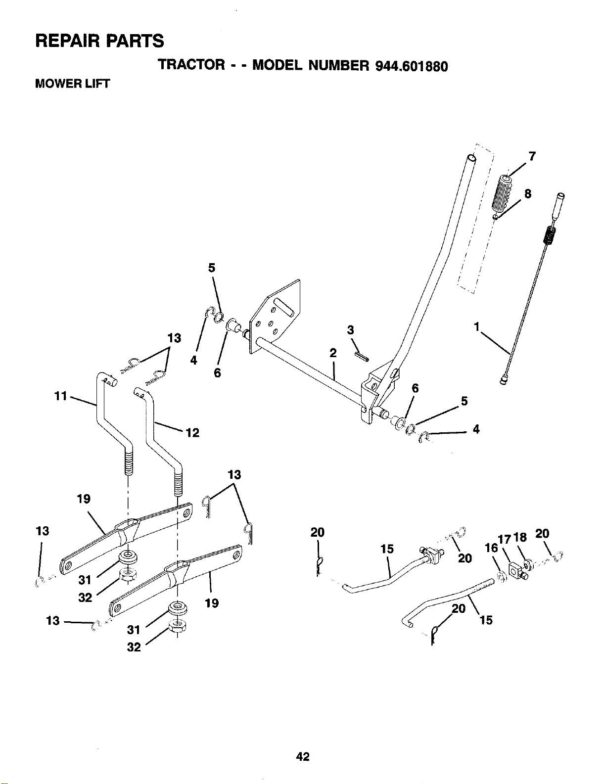
REPAIR PARTS
TRACTOR --MODEL NUMBER 944.601880
MOWER LIFT
7
5
3
2
19
13
42
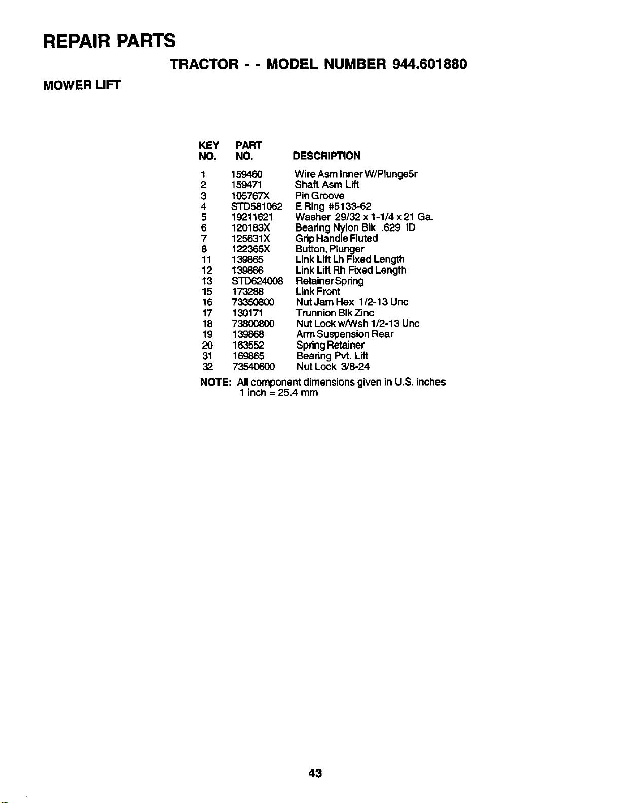
REPAIR PARTS
TRACTOR -- MODEL NUMBER 944.601880
MOWER LIFT
KEY PART
NO. NO. DESCRIPTION
1159460
2159471
3 105767X
4STD581062
519211621
6 120183X
7 125631X
8 122365X
11 139865
12 139866
13 STD624008
15 173288
16 73350800
17 130171
18 73800800
19 139868
2O 163552
31 169865
32 7354O6OO
Wire Asm Inner W/Plunge5r
Shaft Asm Lift
Pin Groove
E Ring #5133-62
Washer 29/32 x 1-1/4 x 21 Ga.
Bearing Nylon BIk .629 ID
Grip Handle Fluted
Button, Plunger
Link Lift Lh Fixed Length
Link Lift Rh Fixed Length
Retainer Spring
Link Front
Nut Jam Hex 1/2-13 Unc
Trunnion BIkZinc
Nut Lock w/Wsh 1/2-13 Unc
Arm Suspension Rear
SpringRetainer
Bearing Pvt. Lift
Nut Lock 3/8-24
NOTE: Allcomponent dimensions given in U.S. inches
1 inch = 25.4 mm
43
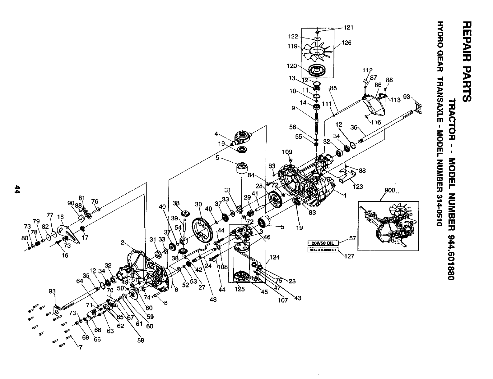
81
77 18
79
73
16
32
64
93 \
_63
69 66
60
58
122-
119-
120"
19
107
_57
\127
88
900
=
o!
m
I
mo |
I- =
0
_=_
=.==
=.
o rrl
_0
O)
0
Co
CO
0
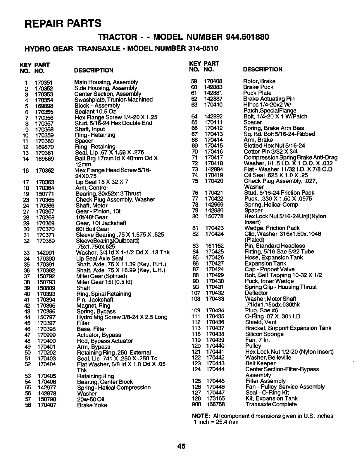
REPAIR PARTS
TRACTOR - - MODEL NUMBER 944.601880
HYDRO GEAR TRANSAXLE - MODEL NUMBER 314-0510
KEY PART KEY PART
NO. NO. DESCRIPTION NO. NO. DESCRIPTION
1170351
2 170352
3 170353
4170354
5169898
6 170355
7 170356
8170357
9 170358
10 170359
11 170360
12 169870
13 170361
14 169869
16 170362
17 170363
18 170364
19 150771
23 170365
24 170366
27 170367
28 170368
29 170369
30 170370
31 170371
32 170389
33 142991
34 170390
35 170391
36 170392
37 150792
38 150793
39 1508O9
40 170393
41 170394
42 170395
43 170396
44 150797
45 170397
46 170398
47 170999
48 170400
49 170401
50 170202
51 170403
52 170404
53 170405
54 170406
55 142977
56 142978
57 150798
58 170407
Main Housing, Assembly 59 170408
Side Housing, Assembly 60 142883
Canter Section, Assembly 61 142881
Swashplate,Trunion Machined 62 142887
Block -Assembly 63 170410
Sealant 10.50z
Hex Flange Screw 1/4-20 X 1.25 64 142892
Stud, 5/16-24 Hex Double End 65 170411
Shaft, Input 66 170412
Ring-Retaining 67 170413
Spacer 68 170414
Ring- Retaining 69 170415
Seal, Lip .67 X 1.58 X .276 70 170416
Ball Brg 17mm Id X 40ram Od X 71 170417
12mm 72 170418
Hex Flange Head Screw 5/16- 73 142884
24)(0.75 74 170419
Lip Seal 18 X32 X7 75 170420
Arm, Control
Bearing, 30x52x13 Thrust 76 170421
Check Plug Assembly, Washer 77 170422
Shaft, Motor 78 142969
Gear- Pinion, 13t 79 142980
10t/48t Gear 80 150778
Gear, 10t Jackshaft
60t BullGear 81 170423
Sleeve Beadng .75 X 1.575 X .625 82 170424
SleeveBearing(Outboard)
.75xl.750x.625 83 161162
Washer, 3/4 Id X1-1/20d X .13 Thk 84 170425
Lip Seal Axle Seal 85 170426
Shaft, Axle .75 X 11.39 (Key, R.H.) 86 170427
Shaft, Axle .75 X 16.99 (Key, L.H.) 87 170424
Miter Gear (Splined) 88 170429
Miter Gear 15t (0.5 Id) 90 170430
Shaft 93 170431
Ring,Spiral Retaining 107 170432
Pin, Jeckshaft 108 170433
Magnet, Ring
Spring, Bypass 109 170434
Hydro Mtg Screw 3/8-24 X 2.5 Long 111 170435
Filter 112 170436
Base, Filter 113 170437
Actuator, Bypass 116 170438
Rod, Bypass Actuator 119 170439
Arm, Bypass 120 170440
Retaining Ring .250 External 121 170441
Seal, Lip .741 X .250 X .250 Tc 122 170442
Flat Washer, 5/8 Id X 1.00d X .05 123 170443
Thk 124 170444
Retaining Ring
Bearing, Center Block 125 170445
Spring- Helical Compression 126 170446
Washer 127 170447
20w-50 Oil 128 173165
BrakeYoke .900 166768
Rotor, Brake
Brake Puck
Puck Plate
Brake Actuating Pin
Hfhcs 1/4-20x2 W/
Patch,SpecialFlange
Bolt, 1/4-20 X 1 W/Patch
Spacer
Spdng, Brake Arm Bias
Sq. Hd. Bolt5/16-24-Ribbed
Arm, Brake
Slotted Hex Nut 5/16-24
Cotter Pin 3/32 X 3/4
Compression Spdng Brake Anti-Drag
Washer, Ht .5 LD. X 10.D. X .032
Flat - Washer 11/32 I.D. X 7/80.D
Oil Seal .625 X 1.0 X .25
Check Plug Assembly, .027,
Washer
Stud, 5/16-24 Friction Pack
Puck, .330 X 1.50 X .0975
Spring, Helical Comp
Spacer
Hex Lock Nut 5/16-24Unjf(Nyion
Insert)
Wedge, Friction Pack
Clip,Washer .316xl .50x.1046
(Plated)
Pin, Standard Headless
Fitting, 5/16 Sae 5/32 Tube
Hose, Expansion Tank
Expansion Tank
Cap - Poppet Valve
Bolt, Self Tapping 10-32 X 1/2
Puck, Inner Wedge
Spdng Clip - Housing Thrust
Deflector
Washer, Motor Shaft
.71idx1.15odx.030thk
Plug, Sae #6
O-Ring .07 X .301 I.D.
Shield, Vent
Bracket, Support Expansion Tank
Silicon Sponge
Fan, 7 In.
Pulley
Hex Lock Nut 1/2-20 (Nylon Insert)
Washer, Belleville
Belt Keeper
Center Section-Filter-Bypass
Assembly
Filter Assembly
Fan - Pulley Service Assembly
Seal - O-Ring Kit
Kit, Expansion Tank
Transaxle Complete
NOTE: All component dimensions given in U.S. inches
1 inch = 25.4 mm
45
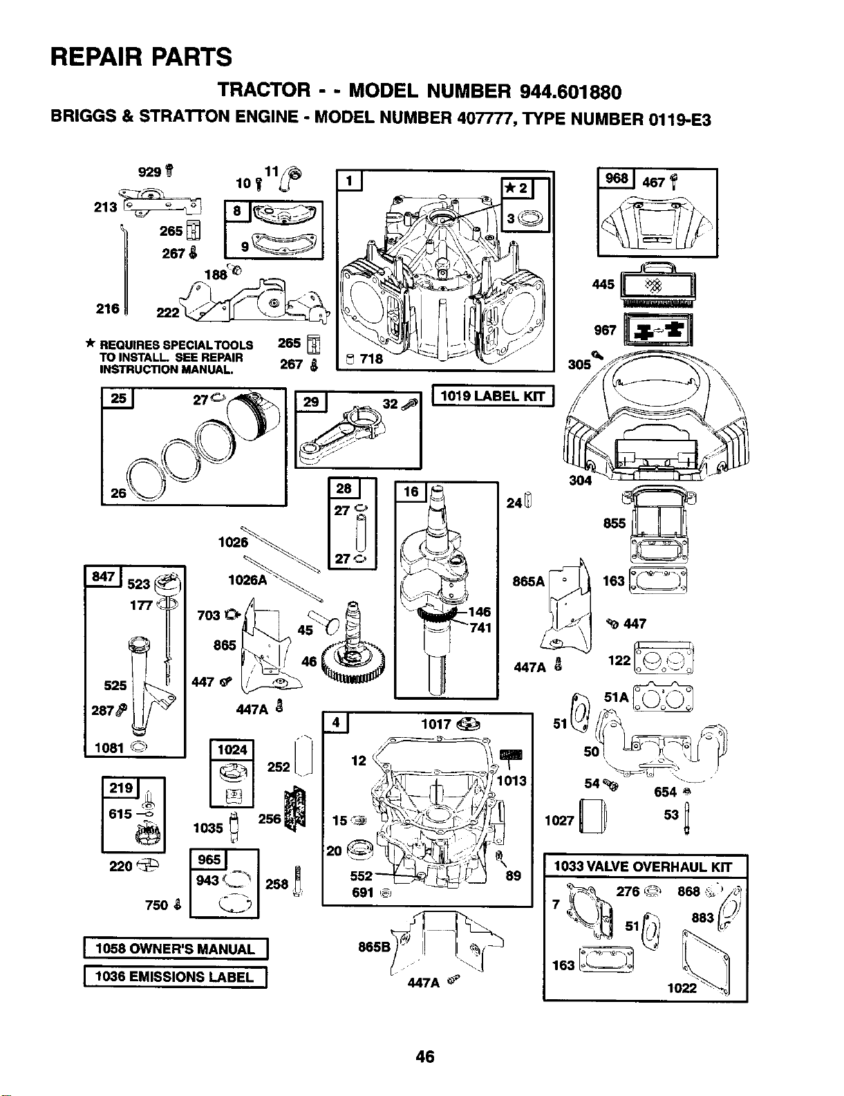
REPAIR PARTS
TRACTOR --MODEL NUMBER 944.601880
BRIGGS & STRATTON ENGINE -MODEL NUMBER 407777, TYPE NUMBER 0119-E3
213__
265
-k REQUIRES SPECIALTOOLS 265
TO INSTALL SEE REPAIR
INSTRUCTION MANUAL. 267
220
750
703
865
447
447A
1035 _256
I1058 OWNER'S MANUAL I
I1,.8EM,SS.ONSLABELI
11
,\
718
I 1019 LABEL KIT J
1022
46
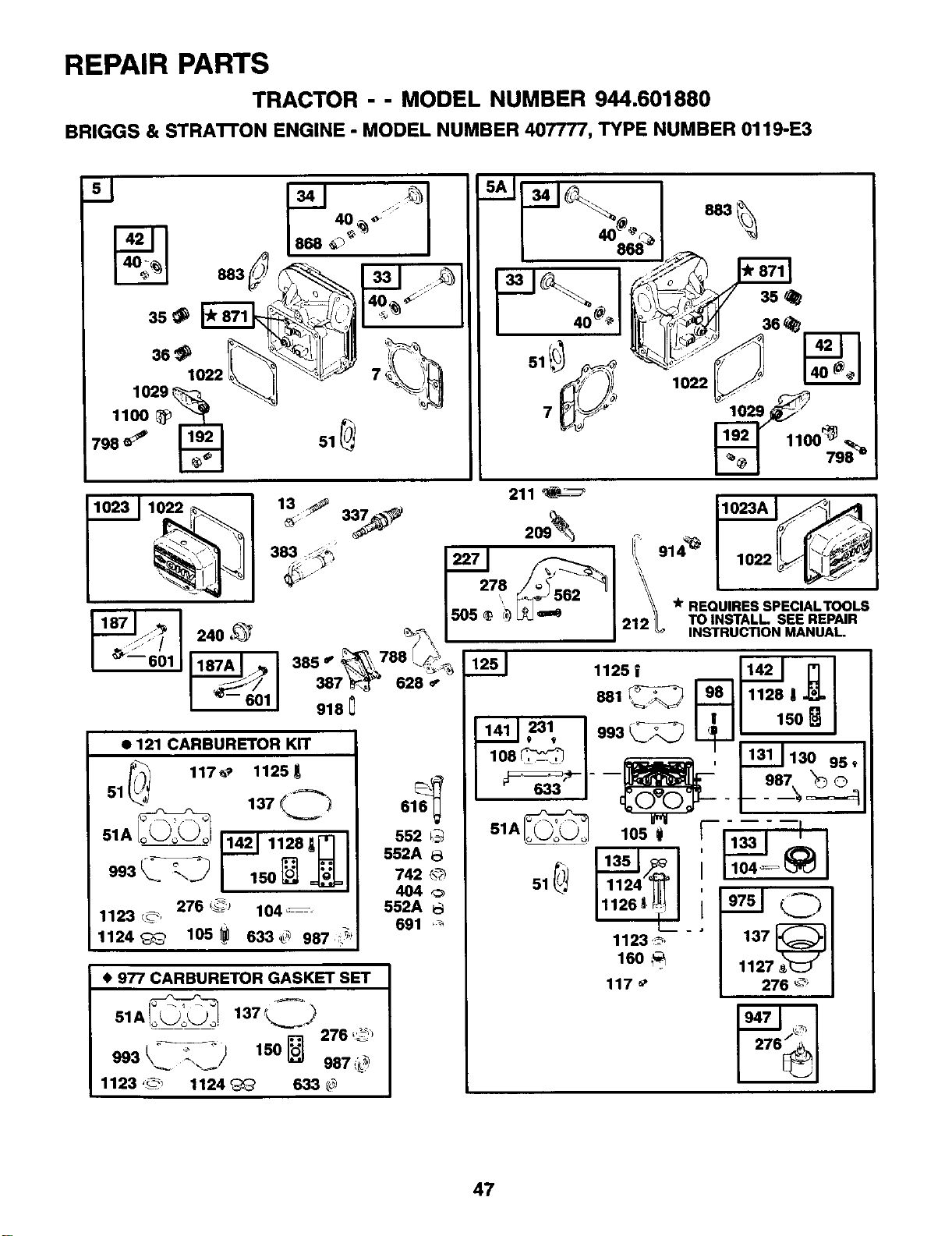
REPAIR PARTS
TRACTOR --MODEL NUMBER 944.601880
BRIGGS & STRA'I-I'ON ENGINE -MODEL NUMBER 407777, TYPE NUMBER 0119-E3
209_ , _,
"2_ * REQUIRES SPEClALTOOLS
21 TO INSTALL SEE REPAIR
INSTRUCTION MANUAL
24+ ,_
_363- 918
628
• 121 CARBURETOR KIT
47
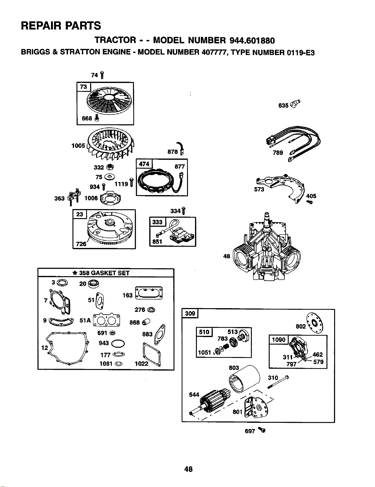
REPAIR PARTS
TRACTOR --MODEL NUMBER 944.601880
BRIGGS & STRATTON ENGINE -MODEL NUMBER 407777, TYPE NUMBER 0119-E3
7,,
1005 t_ 878"_
_8=_ ,,41__._8771
19_75_
334_
48
358 GASKET SET
8_ 2o_
7 51
276
9_ 51A_ 868 _)
2_ 691 @ 8822_
I9_Q 0
177_
1081 _10
8o2_
462
579
Y
801
697
48
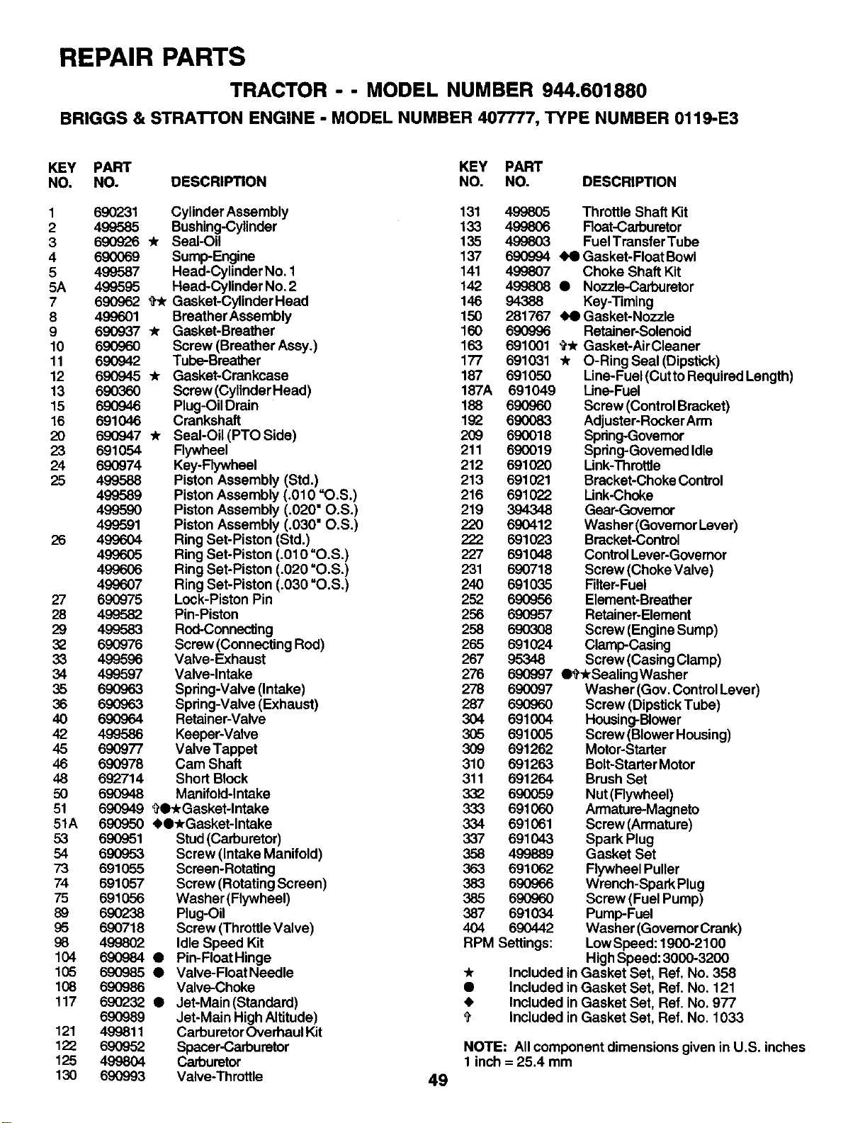
REPAIR PARTS
TRACTOR -- MODEL NUMBER 944.601880
BRIGGS & STRATrON ENGINE -MODEL NUMBER 407777, TYPE NUMBER 0119-E3
KEY PART KEY PART
NO. NO. DESCRIPTION NO. NO. DESCRIPTION
121
122
125
130
1690231 Cylinder Assembly 131 499805
2 499585 Bushing-Cylinder 133 499806
3 690926 Yr Seal-Oil 135 499803
4 690069 Sump-Engine 137 690994
5 499587 Head-Cylinder No. 1 141 499807
5A 499595 Head-Cylinder No.2 142 499808
7 690962 _Gasket-CylinderHead 146 94388
8 499601 Breather Assembly 150 281767
9 690937 _Gasket-Breather 160 690996
10 690960 Screw (Breather Assy.) 163 691001
11 690942 Tube-Breather 177 691031
12 690945 *Gasket-Crankcase 187 691050
13 690360 Screw (Cylinder Head) 187A 691049
15 690946 Plug-Oil Drain 188 690960
16 691046 Crankshaft 192 690083
20 690947 * SeaI-Oil(PTOSide) 209 690018
23 691054 Flywheel 211 690019
24 690974 Key-Flywheel 212 691020
25 499588 Piston Assembly (Std.) 213 691021
499589 Piston Assembly (,010 "O.S.) 216 691022
499590 Piston Assembly (.020" O.S.) 219 394348
499591 Piston Assembly (.030" O.S.) 220 690412
26 499604 Ring Set-Piston (Std.) 222 691023
499605 Ring Set-Piston (.010 "O.S.) 227 691048
499606 Ring Set-Piston (.020 =O.S.) 231 690718
499607 Ring Set-Piston (.030 "O.S.) 240 691035
27 690975 Lock-Piston Pin 252 690956
28 499582 Pin-Piston 256 690957
29 499583 Rod-Connecting 258 690308
32 690976 Screw (Connecting Rod) 265 691024
33 499596 Valve-Exhaust 267 95348
34 499597 Valve-Intake 276 690997
35 690963 Spring-Valve (Intake) 278 690097
36 690963 Spring-Valve (Exhaust) 287 690960
40 690964 Retainer-Valve 304 691004
42 499586 Keeper-Vaive 305 691005
45 690977 Valve Tappet 309 691262
46 690978 Cam Shaft 310 691263
48 692714 Short Block 311 691264
50 690948 Manifold-Intake 332 690059
51 690949 _O_rGasket-lntake 333 691060
51A 690950 41,O_rGasket-lntake 334 691061
53 690951 Stud(Carburetor) 337 691043
54 690953 Screw (Intake Manifold) 358 499889
73 691055 Screen-Rotating 363 691062
74 691057 Screw (Rotating Screen) 383 690966
75 691056 Washer (Rywheel) 385 690960
89 690238 Plug-Oil 387 691034
95 690718 Screw (ThrottleValve) 404 690442
98 499802 Idle Speed Kit RPM Settings:
104 690984 QPin-FloatHinge
105 690985 • Valve-FloatNeedle
108 690986 Valve-Choke •
117 690232 • Jet-Main(Standard) •
690989 Jet-Main High Altitude) $
499811 CarburetorOverhaul Kit
690952 Spacer-Carburetor
499804 Carburetor
690993 Valve-Throttle 49
Throttle Shaft Kit
Roat-Carburetor
Fuel Transfer Tube
Gasket-Float Bowl
Choke Shaft Kit
•Nozzle-Carburetor
Key-Timing
Gasket-Nozzle
Retainer-Solenoid
¢* Gasket-Air Cleaner
"/r O-Ring Seal (Dipstick)
Line-Fuel (Cutto Required Length)
Une-Fuel
Screw (Control Bracket)
Adjuster-Rocker Arm
Spring-Governor
Spdng-Govemed Idle
Link-Throttle
Bracket-Choke Control
Link-Choke
Gear-Govemor
Washer (Govemor Lever)
Bracket-Control
ControlLever-Governor
Screw (Choke Valve)
Filter-Fuel
Element-Breather
Retainer-Element
Screw (Engine Sump)
Clamp-Casing
Screw (Casing Clamp)
O_'_rSeeling Washer
Washer (Gov. Control Lever)
Screw (DipstickTube)
Housing-Blower
Screw (Blower Housing)
Motor-Starter
Bolt-Starter Motor
Brush Set
Nut (Flywheel)
Armature-Magneto
Screw (Armature)
Spark Plug
Gasket Set
Flywheel Puller
Wrench-Spark Plug
Screw (Fuel Pump)
Pump-Fuel
Washer (Govemor Crank)
Low Speed: 1900-2100
HighSpeed: 3000-3200
Included in Gasket Set, Ref. No. 358
Included in Gasket Set, Ref. No. 121
Included in Gasket Set, Ref. No. 977
Included in Gasket Set, Ref. No. 1033
NOTE: All component dimensions given in U.S. inches
1 inch = 25.4 mm
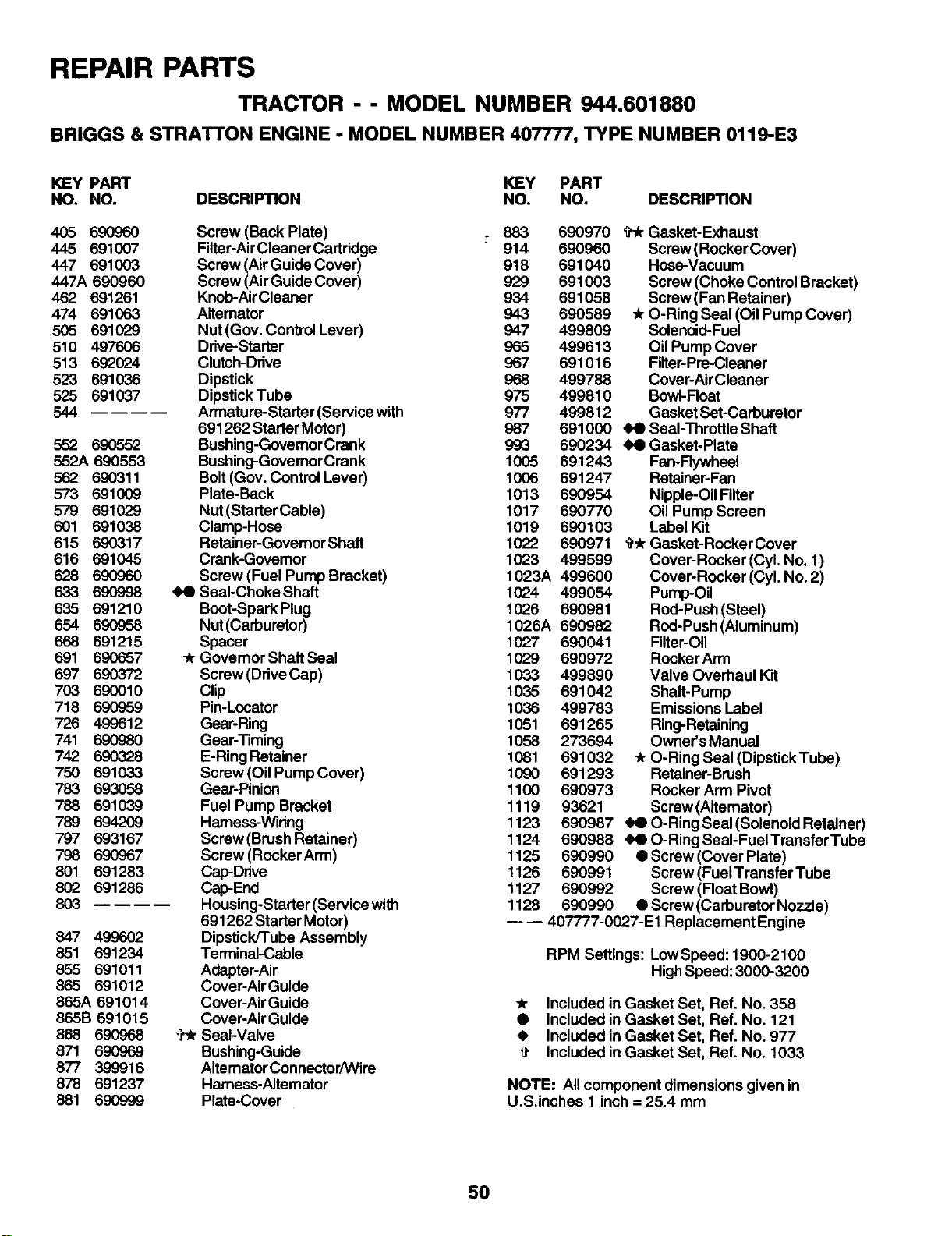
REPAIR PARTS
TRACTOR --MODEL NUMBER 944.601880
BRIGGS & STRATrON ENGINE -MODEL NUMBER 407777, TYPE NUMBER 0119-E3
KEY PART KEY PART
NO. NO. DESCRIPTION NO. NO. DESCRIPTION
405 690960 Screw (Back Plate) :883 690970
445 691007 Filter-AirCleaner Cartridge 914 690960
447 691003 Screw (AirGuide Cover) 918 691040
447A 690960 Screw (AirGuide Cover) 929 691003
462 691261 Knob-AirCleaner 934 691058
474 691063 Alternator 943 690589
505 691029 Nut (Gov. Control Lever) 947 499809
510 497606 Drive-Starter 965 499613
513 692024 Clutch-Drive 967 691016
523 691036 Dipstick 968 499788
525 691037 DipsUckTube 975 499810
544 Armature-Starter (Service with 977 499812
691262 Starter Motor) 987 691000
5,52 690552 Bushing-GovernorCrank 993 690234
552A 690553 Bushing-GovemorCrank 1005 691243
562 690311 Bolt (Gov. Control Lever) 1006 691247
573 691009 Plate-Back 1013 690954
579 691029 Nut(StarterCable) 1017 690770
601 691038 Clamp-Hose 1019 690103
615 690317 Retainer-GovemorShaft 1022 690971
616 691045 Crank-Govemor 1023 499599
628 690960 Screw (Fuel Pump Bracket) 1023A 499600
633 690998 _ SeaI-ChokeShaft 1024 499054
635 691210 Boot-SparkPlug 1026 690981
654 690958 Nut(Carburetor) 1026A 690982
668 691215 Spacer 1027 690041
691 690657 *Governor Shaft Seal 1029 690972
697 690372 Screw(DriveCap) 1033 499890
703 690010 Clip 1035 691042
718 690959 Pin-Locator 1036 499783
726 499612 Gear-Ring 1051 691265
741 690980 Gear-riming 1058 273694
742 690328 E-Ring Retainer 1081 691032
750 691033 Screw (Oil Pump Cover) 1090 691293
783 693058 Gear-Pinion 1100 690973
788 691039 Fuel Pump Bracket 1119 93621
789 694209 Harness-Wiring 1123 690987
797 693167 Screw(Brush Retainer) 1124 690988
798 690967 Screw(RockerArm) 1125 690990
801 691283 Cap-Drive 1126 690991
802 691286 Cap-End 1127 690992
803 Housing-Starter(Servicewith 1128 690990
691262 Starter Motor)
847 499602 Dipstick/Tube Assembly
851 691234 Terminal-Cable
855 691011 Adapter-Air
865 691012 Cover-AirGuide
865A 691014 Cover-Air Guide
865B 691015 Cover-Air Guide
868 690968 ?_ Seal-Valve
871 690969 Bushing-Guide
877 399916 Altemator Connector/Wire
878 691237 Harness-Alternator
881 690999 Plate-Cover
_* Gasket-Exhaust
Screw (RockerCover)
Hose-Vacuum
Screw (Choke Control Bracket)
Screw (Fan Retainer)
* O-Ring Seal (Oil Pump Cover)
Solenoid-Fuel
Oil Pump Cover
Filter-Pre-Cleaner
Cover-AirCleaner
BowI-Roat
Gasket Set-Carburetor
Seal-Throttle Shaft
44 Gasket-Plate
Fan-Flywheel
Retainer-Fan
Nipple-Oil Filter
Oil Pump Screen
Label Kit
_r Gasket-Rocker Cover
Cover-Rocker (Cyl. No. 1)
Cover-Rocker (Cyl. No. 2)
Pump-Oil
Rod-Push (Steel)
Rod-Push (Aluminum)
Filter-Oil
Rocker Arm
Valve Overhaul Kit
Shaft-Pump
Emissions Label
Ring-Retaining
Owner's Manual
_r O-Ring Seal (Dipstick Tube)
Retainer-Brush
Rocker Arm Pivot
Screw (Alternator)
O-Ring Seal (Solenoid Retainer)
O-Ring SeaI-FuelTransfer Tube
•Screw (Cover Plate)
Screw (FuelTransfer Tube
Screw (Float Bowl)
•Screw (Carburetor Nozzle)
--- 407777-0027-E1 Replacement Engine
RPM Settings: LowSpeed: 1900-2100
High Speed: 3000-3200
* Included in Gasket Set, Ref. No. 358
•Included in Gasket Set, Ref. No. 121
Included in Gasket Set, Ref. No. 977
Included in Gasket Set, Ref. No. 1033
NOTE: Allcomponent dimensions given in
U.S.inches 1 inch= 25.4 mm
50

SUGGESTED GUIDE FOR SIGHTING SLOPES FOR SAFE OPERATION
O1
SIGHTING "" "-.. _CUT
r Ts
ONLY RIDE UP AND DOWN HILL,
NOT ACROSS HILL
SIGHT AND HOLD THIS LEVEL WITH
SKY LINE OR TREE.
15° MAX.
I_ Operate your Tractor up and down the face of slopes (not I
I
greater than 15°), never across the face. Make turns gradu- I
ally to prevent tipping or loss of control. Exercise extreme
caution when changing direction on slopes.

ISEARS
HomeCentral"]
Get it fixed, at your home or ours!
1-800-4-MY-HOME®
(1-800-469-4663)
Call 24 hours a day, 7 days a week
www.sears.ca
For Parts call
1-800-4-MY-HOME®
(1-800-4694663)
Call 24 hours aday, 7 days aweek
To purchase or inquire about a Sears Maintenance Agreement:
1-800-361-6665
Mon. to Sat.
Pour service en francais:
1-887-LE-FOYER®
(1-877-533-6937)
ICentredufoyeL1
SF.AJ $J
177331 Re,.,.1 12.20.00 JH PRINTED IN U.S.A.