
1
Owner’s Manual
B093-00X-2E4U-X Resilience Gateway
B097-016/048 Console Server
B098-016/048 and B098-016-V
Infrastructure Manager
1111 W. 35th Street, Chicago, IL 60609 USA • tripplite.com/support
Copyright © 2022 Tripp Lite. All rights reserved.
WARRANTY REGISTRATION
Register your product today and be
automatically entered to win an ISOBAR
®
surge protector in our monthly drawing!
tripplite.com/warranty

2
Table of Contents
1. Introduction 7
2. Installation 8
2.1 Models 8
2.2 Power Connection 8
2.2.1 Models with Internal 8
AC Power Supplies
2.2.2 Models with External 9
Power Supplies
2.3 Network Connection 10
2.4 Serial Port Connection 10
2.5 USB Port Connection 11
2.6 Fitting Cellular SIM and Antennas 11
2.6.1 B093-00X-2E4U-V Models 11
2.6.2 B098-016-V Models 11
3. System Configuration 12
3.1 Management Console Connection 12
3.1.1 Connected Computer Setup 12
3.1.2 Browser Connection 13
3.2 Administrator Setup 14
3.2.1 Change Default Root System 14
Password
3.2.2 Set Up New Administrator 14
3.2.3 Name the System 15
3.3 Network Configuration 16
3.3.1 IPv6 Configuration 17
3.3.2 Dynamic DNS (DDNS) 17
Configuration
3.4 Services and Service Access 19
3.4.1 Brute Force Protection 22
3.5 Communications Software 23
3.5.1 SDT Connector 23
3.5.2 PuTTY 24
3.5.3 SSHTerm 24
3.6 Management Network Configuration 25
3.6.1 Enable the Management LAN 25
3.6.2 Configure the DHCP Server 27
3.6.3 Select Failover or Broadband OOB 29
3.6.4 Aggregating the Network Ports 30
3.6.5 Static Routes 31
3.7 Configuration over DHCP (ZTP) 31
4. Serial Port, Host, Device and 34
User Configuration
4.1 Configure Serial Ports 34
4.1.1 Common Settings 35
4.1.2 Console Server Mode 35
4.1.3 SDT Mode 40
4.1.4 Device (RPC, UPS, EMD) Mode 40
4.1.5 Terminal Server Mode 40
4.1.6 Serial Bridging Mode 41
4.1.7. Syslog 41
4.1.8 USB Consoles 42
4.1.9 Link Layer Discovery Protocol 42
(LLDP)
4.2 Add and Edit Users 43
4.2.1 Set Up New Group 44
4.2.2 Set Up New Users 45
4.3 Authentication 46
4.4 Network Hosts 46
4.5 Trusted Networks 48
4.6 Serial Port Cascading 49
4.6.1 Automatically Generate and 50
Upload SSH keys
4.6.2 Manually Generate and 51
Upload SSH Keys
4.6.3 Configure the Secondary Units 52
and their Serial Ports
4.6.4 Managing the Secondary 53
Serial Ports
4.7 Managed Devices 53
4.8 IPsec VPN 55
4.8.1 Enable the VPN Gateway 55
4.9 OpenVPN 57
4.9.1 Enable the OpenVPN 58
4.9.2 Configure as Server or Client 59
4.9.3 Set Up Windows OpenVPN 62
Client and Server
4.10 PPTP VPN 65
4.10.1 Enable the PPTP VPN Server 66
4.10.2 Add a PPTP User 67
4.10.3 Set Up a Remote PPTP Client 68
4.11 IP Passthrough 69
4.11.1 Downstream Router Setup 69
4.11.2 IP Passthrough Pre-Configuration 69
4.11.3 IP Passthrough Configuration 70
4.11.4 Service Intercepts 70
4.11.5 IP Passthrough Status 70
4.11.6 Caveats 71

3
Table of Contents
5. Firewall, Failover and OOB Access 72
5.1 Dialup Modem Connection 72
5.2 OOB Dial-In Access 72
5.2.1 Configure Dial-In PPP 73
5.2.2 Using SDT Connector Client 75
5.2.3 Set Up Windows XP or Later Client 75
5.2.4 Set Up Earlier Windows Clients 76
5.2.5 Set Up Linux Clients 76
5.3 Dial-Out Access 76
5.3.1 Always-On Dial-Out 77
5.3.2 Failover Dial-Out 78
5.4 OOB Broadband Ethernet Access 79
5.5 Broadband Ethernet Failover 80
5.6 Cellular Modem Connection 81
5.6.1 Connecting to a 4G LTE 82
Carrier Network
5.6.2 Verifying the Cellular Connection 83
5.6.3 Cellular Modem Watchdog 84
5.6.4 Dual SIM Failover 85
5.6.5 Automatic SIM Slot Detection 85
5.6.6 Multi-Carrier Cellular Support 86
5.7 Cellular Operation 87
5.7.1 Set Up OOB Access 88
5.7.2 Set Up Cellular Failover 89
5.7.3 Cellular Routing 90
5.7.4 Set Up Cellular CSD Dial-In 91
5.8 Firewall and Forwarding 92
5.8.1 Configuring Network Forwarding 92
and IP Masquerading
5.8.2 Configuring Client Devices 94
5.8.3 Port / Protocol Forwarding 96
5.8.4 Firewall Rules 98
5.8.5 Packet State Matching in 100
Firewall Rules
6. SSH Tunnels and SDT Connector 102
6.1 Configuring for SSH Tunneling 102
to Hosts
6.2 SDT Connector Client Configuration 102
6.2.1 SDT Connector Client Installation 103
6.2.2 Configuring a New Gateway in 103
the SDT Connector Client
6.2.3 Auto-Configure SDT Connector 104
Client with the User’s Access
Privileges
6.2.4 Make an SDT Connection 105
Through the Gateway to a Host
6.2.5 Manually Adding Hosts to the 105
SDT Connector Gateway
6.2.6 Manually Adding New Services 106
to the New Hosts
6.2.7 Adding a Client Program to Be 108
Started for the New Service
6.2.8 Dial-In Configuration 109
6.3 SDT Connector to Management 110
Console
6.4 SDT Connector: Telnet or SSH 111
Connect to Serially Attached Devices
6.5 Using SDT Connector for 112
Out-of-Band (OOB) Connection to
the Gateway
6.6 Importing (and Exporting) 113
Preferences
6.7 SDT Connector Public Key 113
Authentication
6.8 Setting up SDT for Remote 114
Desktop Access
6.8.1 Enable Remote Desktop on the 114
Target Windows Computer to
Be Accessed
6.8.2 Configure the Remote Desktop 115
Connection Client
6.9 SDT SSH Tunnel for VNC 116
6.9.1 Install and Configure the VNC 116
Server on the Computer to be
Accessed
6.9.2 Install, Configure and Connect 118
the VNC Viewer
6.10 Using SDT to IP Connect to Hosts 119
that are Serially Attached to the
Gateway
6.10.1 Establish a PPP Connection 120
between the Host COM Port and
Console Server
6.10.2 Set Up SDT Serial Ports on 122
Console Server
6.10.3 Set Up SDT Connector to SSH 122
Port Forward over Console Server
Serial Port
6.11 SSH Tunneling Using Other SSH 122
Clients (e.g. PuTTY)
6.12. VNC Security 125

4
Table of Contents
7. Alerts, Auto-Response and Logging 126
7.1 Configure Auto-Response 126
7.2 Check Conditions 128
7.2.1 Environmental 128
7.2.2 Alarms and Digital Inputs 128
7.2.3 UPS/Power Supply 129
7.2.4 UPS Status 129
7.2.5 Serial Login, Signal or Pattern 130
7.2.6 USB Console Status 130
7.2.7 ICMP Ping 131
7.2.8 Link Layer Discovery Protocol 132
(LLDP)
7.2.9 Cellular Data 132
7.2.10 Custom Check 133
7.2.11 SMS Command 133
7.2.12 Log In/Out Check 133
7.2.13 Network Interface Event 135
7.2.14 Routed Data Usage Check 136
7.3 Trigger Actions 136
7.3.1 Send Email 137
7.3.2 Send SMS 137
7.3.3 Perform RPC Action 137
7.3.4 Run Custom Script 137
7.3.5 Send SNMP Trap 137
7.3.6 Send Nagios Event 138
7.3.7 Perform Interface Action 138
7.4 Resolve Actions 138
7.5
Configure SMTP, SMS, SNMP and/or
139
Nagios Service for Alert Notifications
7.5.1 Send Email Alerts 139
7.5.2 Send SMS Alerts 140
7.5.3 Send SNMP Trap Alerts 141
7.5.4 Send Nagios Event Alerts 143
7.6 Logging 143
7.6.1 Log Storage 144
7.6.2 Serial Port Logging 145
7.6.3 Network TCP and UDP 145
Port Logging
7.6.4 Auto-Response Event Logging 146
7.6.5 Power Device Logging 146
8. Power, Environment and Digital I/O 147
8.1 Remote Power Control (RPC) 147
8.1.1 RPC Connection 147
8.1.2 RPC Access, Privileges and Alerts 151
8.1.3 User Power Management 151
8.1.4 RPC Status 152
8.2 Uninterruptible Power Supply (UPS) 153
Control
8.2.1 Managed UPS Connections 153
8.2.2 Remote UPS Management 156
8.2.3 Controlling UPS Powered 157
Computers
8.2.4 UPS Alerts 157
8.2.5 UPS Status 158
8.2.6 Overview of Network UPS 159
Tools (NUT)
8.3 Environmental Monitoring 160
8.3.1 Connecting the EMD and 161
its Sensors
8.3.2 Adding EMDs and Configuring 162
the Sensors
8.3.3 Environmental Alerts 163
8.3.4 Environmental Status 164
9. Authentication 165
9.1 Authentication Configuration 165
9.1.1 Local Authentication 165
9.1.2 TACACS Authentication 166
9.1.3 RADIUS Authentication 167
9.1.4 LDAP Authentication 168
9.1.5 RADIUS/TACACS User 171
Configuration
9.1.6 Group Support with Remote 172
Authentication
9.1.7 Remote Groups with RADIUS 172
Authentication
9.1.8 Remote Groups with LDAP 174
Authentication
9.1.9 Remote Groups with TACACS+ 175
Authentication
9.1.10 Idle Timeout 176
9.1.11 Kerberos Authentication 176
9.1.12 Authentication Testing 177
9.2 PAM 177
(Pluggable Authentication Modules)
9.3 SSL Certificate 178

5
Table of Contents
10. Nagios Integration 181
10.1 Nagios Overview 181
10.2 Configuring Nagios 181
Distributed Monitoring
10.2.1 Enable Nagios on the 182
Console Server
10.2.2 Enable NRPE Monitoring 183
10.2.3 Enable NSCA Monitoring 184
10.2.4 Configure Selected Serial Ports 185
for Nagios Monitoring
10.2.5 Configure Selected Network 185
Hosts for Nagios Monitoring
10.2.6 Configure the Upstream Nagios 186
Monitoring Host
10.3 Advanced Distributed Monitoring 187
Configuration
10.3.1 Sample Nagios Configuration 187
10.3.2 Basic Nagios Plug-Ins 189
10.3.3 Additional Plug-Ins 190
10.3.4 Number of Supported Devices 191
10.3.5 Distributed Monitoring Usage 192
Scenarios
11. System Management 194
11.1 System Administration and Reset 194
11.2 Upgrade Firmware 195
11.3 Configure Date and Time 195
11.4 Configuration Backup 297
11.5 Delayed Configuration Commit 298
11.6 FIPS Mode 201
12. Status Reports 202
12.1 Port Access and Active Users 202
12.2 Statistics 203
12.3 Support Reports 203
12.4 Syslog 204
12.5 Dashboard 205
12.5.1 Configuring the Dashboard 205
12.5.2 Creating Custom Widgets for the 207
Dashboard
13. Management 208
13.1 Device Management 208
13.2 Port and Host Logs 208
13.3 Terminal Connection 209
13.3.1 Web Terminal 209
13.3.2 SDT Connector Access 211
13.4 Power Management 211
14. Configuration from the 212
Command Line
14.1 Accessing Config from the 212
Command Line
14.1.1 Serial Port Configuration 215
14.1.2 Adding and Removing Users 216
14.1.3 Adding and Removing 217
User Groups
14.1.4 Authentication 218
14.1.5 Network Hosts 219
14.1.6 Trusted Networks 220
14.1.7 Cascaded Ports 220
14.1.8 UPS Connections 221
14.1.9 RPC Connections 222
14.1.10 Environmental 223
14.1.11 Managed Devices 223
14.1.12 Port Log 224
14.1.13 Alerts 224
14.1.14 SMTP and SMS 226
14.1.15 SNMP 227
14.1.16 Administration 227
14.1.17 IP Settings 227
14.1.18 Date and Time Settings 228
14.1.19 Dial-In Settings 229
14.1.20 DHCP Server 229
14.1.21 Services 230
14.1.22 NAGIOS 231
15. Advanced Configuration 232
15.1 Custom Scripting 232
15.1.1 Custom Script to Run 232
when Booting
15.1.2 Running Custom Scripts when 232
Alerts are Triggered
15.1.3 Sample Script - Power Cycling 233
on Pattern Match
15.1.4 Sample Script - Multiple Email 233
Notifications on Each Alert
15.1.5 Deleting Configuration Values 234
from the CLI
15.1.6 Power Cycle Any Device upon a 236
Ping Request Failure
15.1.7 Running Custom Scripts when a 237
Configurator is Invoked
15.1.8 Backing-Up the Configuration 237
and Restoring Using a Local
USB Drive
15.1.9 Backing Up the Configuration 238
Off-Box
15.2 Advanced Portmanager 239
15.2.1 Portmanager Commands 239
15.2.2 External Scripts and Alerts 242

6
Table of Contents
15.3 Raw Access to Serial Ports 243
15.3.1 Access to Serial Ports 243
15.3.2 Accessing the Console/ 243
Modem Port
15.4 IP Filtering 244
15.5 SNMP Status Reporting 244
15.5.1 Retrieving Status Information 244
using SNMP
15.5.2 Check Firewall Rules 245
15.5.3 Enable SNMP Service 245
15.5.4 Adding Multiple Remote 247
SNMP Managers
15.6 Secure Shell (SSH) Public Key 248
Authentication
15.6.1 SSH Overview 248
15.6.2 Generating Public Keys (Linux) 249
15.6.3 Installing the SSH Public/Private 250
Keys (Clustering)
15.6.4 Installing SSH Public Key 250
Authentication (Linux)
15.6.5 Generating Public/Private Keys 251
for SSH (Windows)
15.6.6 Fingerprinting 253
15.6.7 SSH Tunneled Serial Bridging 253
15.6.8 SDT Connector Public Key 256
Authentication
15.7 Secure Sockets Layer (SSL) 256
Support
15.8 HTTPS 256
15.8.1 Generating an Encryption Key 256
15.8.2 Generating a Self-Signed 257
Certificate with OpenSSL
15.8.3 Installing the Key and Certificate 257
15.8.4 Launching the HTTPS Server 257
15.9 Power Strip Control 258
15.9.1 PowerMan Tool 258
15.9.2 Pmpower tool 259
15.9.3 Adding New RPC Devices 260
15.10 IPMItool 261
15.11 Custom Development Kit (CDK) 263
15.12 SMS Server Tools 264
15.13 Multicast 264
15.14 Bulk Provisioning 265
15.15 Zero Touch Provisioning 265
15.15.1 Preparation 265
15.15.2 Example ISC DHCP Server 265
Configuration
15.15.3 Set Up an Untrusted LAN 266
15.15.4 How it Works 266
15.16 Internal Storage 267
15.16.1 Filesystem Location of 267
FTP/TFTP Directory
15.16.2 Filesystem Location of 267
Portmanager Logs
15.16.3 Configuring FTP/TFTP Directory 268
15.16.4 Mounting a Preferred USB Disk 268
by Label
APPENDIX A: Linux Commands and 269
Source Code
APPENDIX B: Hardware Specification 273
APPENDIX C: Safety and Certifications 273
APPENDIX D: Connectivity, TCP Ports 274
and Serial I/O
APPENDIX E: Terminology 277
APPENDIX F: End User License 280
Agreements
APPENDIX G: Service and 885
Limited Warranty

7
Important Safety Instructions
Please take care to follow the safety precautions below when installing and operating the console server:
- Do not remove the metal covers. There are no operator serviceable components inside. Opening or removing the cover may
expose you to dangerous voltage that may cause fire or electric shock. Refer all service to Tripp Lite qualified personnel.
- To avoid electric shock the power cord protective grounding conductor must be connected through to ground.
- Always pull on the plug, not the cable, when disconnecting the power cord from the socket.
Do not connect or disconnect the console server during an electrical storm. Also, it is recommended you use a Tripp Lite surge
protector or UPS to protect the equipment from transient power fluctuations.
Proper backup systems and necessary safety devices should be utilized to protect against injury,
death or property damage due to system failure. Such protection is the responsibility of the user.
This console server device is not approved for use as a life-support or medical system.
Any changes or modifications made to this console server device without the explicit approval or
consent of Tripp Lite will void Tripp Lite of any liability or responsibility of injury or loss caused by
any malfunction.
This equipment is for indoor use and all the communication wirings are limited to inside of the
building.
1. Introduction
Tripp Lite’s B093-, B097- and B098-Series console / terminal servers are among the most advanced platform available
today. In a secure, desktop/rack-mountable appliance, B093-, B097- and B098-console servers offer in-band, out-band and
cellular management solutions for serial console ports, servers, virtual servers, service processors, UPS systems and PDUs,
environmental monitoring and more. Available in 4- and 8-port models, B093-, B097- and B098- console / terminal servers
allow system administrators to securely access and control their data centers and networks from anywhere in the world. These
enterprise-grade units are equipped with a built-in cellular modem, dual Gigabit Ethernet NIC, 4 GB internal NAND flash, four
USB 2.0 console ports, a digital I/O port, and run on Linux for scalability and reduced downtime.
B093-, B097- and B098- console servers also offer advanced software features surpassing the requirements of even the most
demanding applications. These features include network UPS tools for UPS monitoring, PowerMan for integrated PDU and
UPS functions with in-session hotkey support, pattern match alerting, open access to the Linux shell for scripting, heartbeat
monitoring with automatic failover, Cisco pinouts and much more.
8
2. Installation
2.1 Models
Each model contains a different number of network/serial/USB ports, power supply type and wireless configuration:
Model
Serial
USB
10/100 Ethernet
10/100/1000 Ethernet
Flash
Console Port
V.92 Modem
Wireless
Cellular
Power
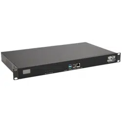
B093-004-2E4U 4 4 - 2 4GB - - - - External DC Power Supply
B093-008-2E4U 8 4 - 2 4GB - - - - External DC Power Supply
B093-004-2E4U-V 4 4 - 2 4GB - - 4G Multi Carrier External DC Power Supply
B093-008-2E4U-V 8 4 - 2 4GB - - 4G Multi Carrier External DC Power Supply
B093-008-2E4U-M 8 4 - 2 4GB - Y - - External DC Power Supply
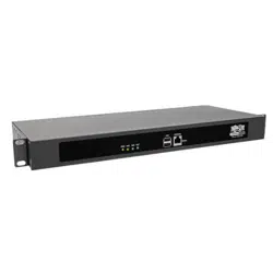
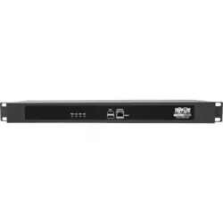
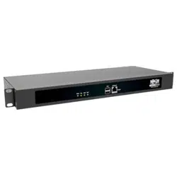
B097-016 16 2 - 2 4GB 1 - - - Dual AC
B097-048 48 2 - 2 4GB 1 - - - Dual AC
B098-016 16 2 - 2 16GB 1 Y WAP, 4G opt - Dual AC
B098-048 48 2 - 2 16GB 1 Y WAP, 4G opt - Dual AC
B098-016-V 48 2 - 2 16GB 1 Y WAP, 4G opt Multi Carrier Dual AC
2.2 Power Connection
To avoid physical and electrical hazard, please read Appendix C: Safety & Certifications.
• Unpack your console server kit, verify you have all of the accessories and ensure all items appear to be in good working
order.
• If you plan to install the console server in a rack, you will need to attach the rack-mount brackets supplied with the unit. See
Appendix C: Safety & Certifications for more information.
• Connect your console server to the network, to the serial ports of the controlled devices, and to power supply.
2.2.1 Models with Internal AC Power Supplies
Some console server models use dual universal AC power supplies with built-in auto failover (see 2.1 Models for model
listing). These power supplies accept AC input voltage between 100 and 240V AC with a frequency of 50 or 60 Hz. The total
power consumption per console server is less than 30W.
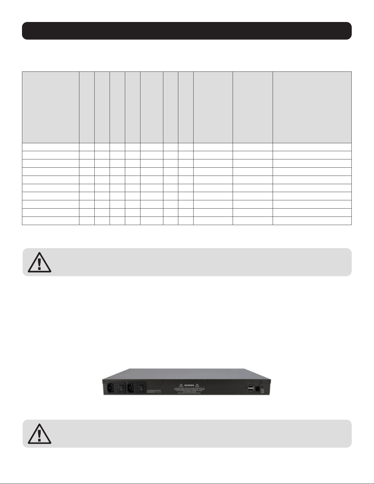
Two IEC AC power inlets are located at the rear of the unit. These power inlets use conventional IEC power cords. Power cords
for various regions are available at www.tripplite.com, though a North American power cord is provided by default.
To avoid electrical shock, the power cord grounding conductor must be connected to ground.

9
2. Installation
2.2.2 Models with External Power Supplies
Some console servers use an external 12V wall-mount power supply (see 2.1 Models for model listing). These models include
a selection of wall socket adapters for each geographic region (North America, Europe, U.K., Japan and Australia). The power
supply unit’s 12V DC connector plugs into the 12V DC (PWR) power jack located on the side of the unit.
• Plug in the power supply AC power cable and the DC power cable.
• Turn on the unit and confirm the Power LED (PWR) is illuminated.
2.3 Network Connection
All console server models include Ethernet ports.
Network connections are made using Cat5e patch cables (Tripp Lite N001 and N002 Series Cables, sold separately). Connect
the unit’s LAN port to an Ethernet network. Upon first connecting and configuring the console server to a network, you must
connect a computer to the console server’s primary network port.
Ensure you only connect the LAN port to an Ethernet network that supports 10/100, or 10/100/1000 (B098, B097, B093
only).
The B098 has four physical input ports which are logically presented as two ports (NET1 & NET2). Each logical port consists of
a copper 10/100/1000 port and a fiber-optic small form-factor pluggable (SFP) module slot.
On all devices with logically-paired SFP and RJ45 ports, you can use only one of the two physical ports at a time: either the
SFP module port or the 10/100/1000 port. The fiber-optic medium (ie, the SFP module) has priority over the copper medium
(ie the RJ45 port). Only if the SFP module is not plugged in, does the RJ45 copper link becomes active. This applies regardless
of the connection order. If the SFP module is plugged in after the copper medium has established a link, the copper link is
disconnected and the fiber-optic medium becomes active.
For the initial configuration of the console server you must connect a computer to the console server’s principal network port.
This port is labeled LAN1 on B093 and NET1 on B098 and B097.
10
Conventional Cat5 cabling with RJ45 jacks is used for serial connections. Before connecting the console port of an external
device to the console server’s serial port, confirm the device supports standard RS-232C (EIA-232).
Select console server models also have a DB9 LOCAL (Console/Modem) port.
2.5 USB Port Connection
• Tripp Lite console servers have one or more USB ports. B098
models have USB 3.0 ports. On other models these ports are
mostly USB 2.0.
• Console servers ship with internal USB flash memory ranging from
2 GB to 16 GB, which can be used for extended log file storage.
• External USB devices (including USB hubs) can be plugged into
any Console Server USB port.
2. Installation
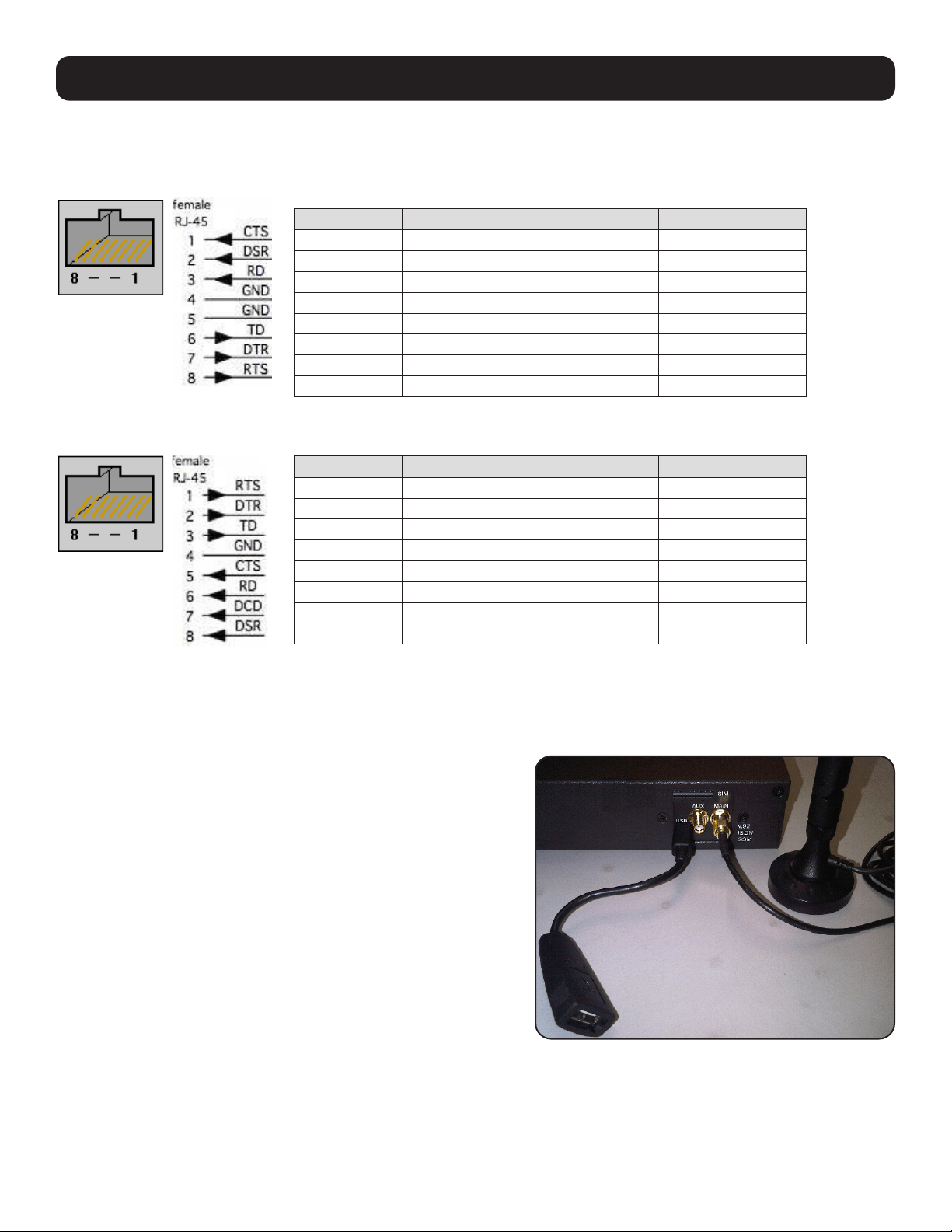
2.4 Serial Port Connection
Tripp Lite console servers use the RJ45 pin-out standard used by Cisco. Use straight-through RJ45 cabling to connect to Cisco,
Juniper, SUN equipment and more.
The B098 console servers can select this pinout. This makes it easy to replace Avocent Cyclades products, and is convenient
for use with rolled RJ45 cable:
PIN SIGNAL DEFINITION DIRECTION
1 CTS Clear To Send Input
2 DSR Data Set Ready Input
3 RXD Receive Data Input
4 GND Signal Ground NA
5 GND Signal Ground NA
6 TXD Transmit Data Output
7 DTR Data Terminal Ready Output
8 RTS Request To Send Output
PIN SIGNAL DEFINITION DIRECTION
1 CTS Clear To Send Input
2 DSR Data Set Ready Input
3 RXD Receive Data Input
4 GND Signal Ground NA
5 GND Signal Ground NA
6 TXD Transmit Data Output
7 DTR Data Terminal Ready Output
8 RTS Request To Send Output
11
2. Installation
2.6 Fitting Cellular SIM and Antennas
The B093 -V models and the B098-016-V have internal 4G LTE cellular modems. Each cellular modem requires at least one
SIM card to be installed and two external cellular antennas to be attached. For more detail:
2.6.1 B093-00X-2E4U-V Models
B093-008-2E4U-V models come with internal 4G LTE modems and dual mini-SIM card slots.
-V models work with Verizon USA by default but can be reconfigured to work with AT&T USA.
Whichever carrier you choose, their SIM card activates the data plan and must be installed before powering on the device.
On single-SIM models, slide the carrier’s SIM card into the slot on the front of the device, making sure the contacts are facing
upwards and the notch is pointing outwards as the card slides into place.
Dual-SIM models use a SIM cradle. The cradle holds the SIM card or cards and slides into the dual-SIM-card slot on the front
of the device. The bottom slot is the default slot. If you have a dual-SIM model and only one SIM card, insert the card into the
bottom slot of the SIM cradle. No matter the specific configuration, SIM cards go into the cradle with the contacts upwards
and the notch inward and adjacent to the longer cradle arm.
B093 -V models come with two external 7-band celluar antennas. Screw the provided antennas on to the main Cell (M) and
diversity Cell (A) SMA connectors on the rear panel. An external GPS passive antenna with magnetic base, SMA connector and
2-meter cable is available (Part #569008). It is screwed on to the GPS SMA connector on the rear panel.
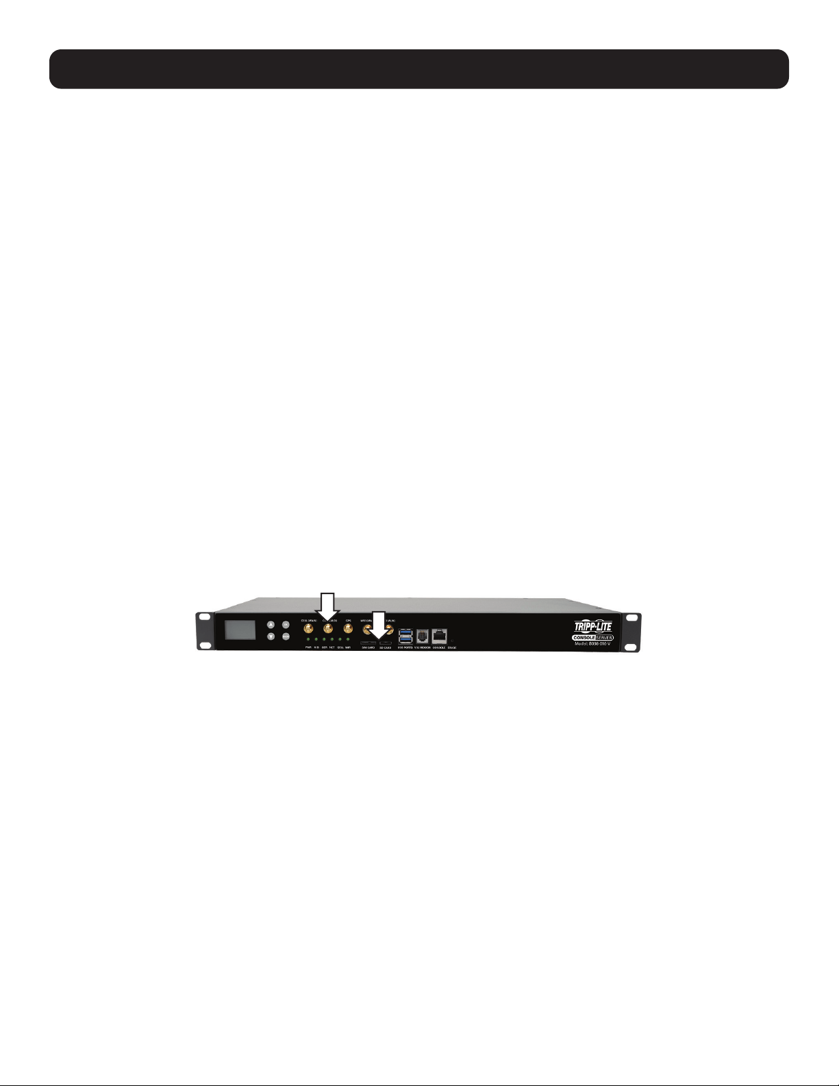
2.6.2 B098-016-V Models
The B098-016-V models have a SIM card slot and three SMA cellular antenna connectors (for cellular with receive diversity
and GPS).
-V models default to Verizon but are multicarrier in the United States and also work with AT&T.
Included in the kit are two cellular antennas (with one 10-foot coaxial cable and magnetic antenna screw mount base for
mounting outside the rack). If cellular signal strength is an issue, higher gain and directional antennas can be sourced.
Before powering on the B098 -V:
• Screw one antenna (or antenna cable) onto the CELL (MAIN) screw mount (1) and the diversity antenna, onto the CELL
(AUX) connector.
Note: If you have purchased a GPS antenna, screw it on to GPS
• Your carrier will provide you with a SIM card. Insert the card into the SIM CARD slot and it will lock into place (2)
Note: Insert SIM card with contacts facing downwards.
1
2

12
3. System Configuration
This chapter provides step-by-step instructions for the initial configuration of your console server and how to connect it to the
Management or Operational LAN.
Notes:
• System configuration must be done by a person with Administrator access.
• For guidance on configuring large numbers of Tripp Lite console servers and/or automating provisioning, sections 15.15 Bulk
Provisioning and 15.16 Zero Touch Provisioning.
3.1 Management Console Connection
Your console server ships configured with a default IP Address 192.168.0.1 Subnet Mask 255.255.255.0
Directly connect a computer to the console server.
Note: For initial configuration, it is recommended that the console server be directly connected to a single computer. However, if you choose
to connect your LAN before completing the initial setup steps, it is important that you ensure there are no other devices on the LAN with an
address of 192.168.0.1, and
the console server and the computer are on the same LAN segment, with no interposed router devices.
3.1.1 Connected Computer Setup
To configure the console server with a browser, the connected PC/workstation should have an IP address in the same range as
the console server (for example, 192.168.0.100):
• To configure the IP Address of your Linux or UNIX computer, run ifconfig.
• For Windows PCs:
Click Start -> (Settings ->) Control Panel and double-click Network Connections (for 95/98/Me, double-click Network).
Right click on Local Area Connection and select Properties.
Select Internet Protocol (TCP/IP) and click Properties.
Select Use the following IP address and enter the following details:
IP address: 192.168.0.100
Subnet mask: 255.255.255.0
If you want to retain your existing IP settings for this network connection, click Advanced and Add the above as a secondary
IP connection.
• If it is not convenient to change your computer network address, you can use the ARP-Ping command to reset the console
server IP address. To do this from a Windows PC:
Click Start -> Run (or select All Programs -> Accessories -> Run).
Type cmd and click OK to bring up the command line.
Type arp –d to flush the ARP cache.
Type arp –a to view the current ARP cache (this should be empty).
13
3. System Configuration
Now add a static entry to the ARP table and ping the console server to assign the IP address to the console server. In the
example below, a console server has a MAC Address 00:06:67:12:DA:F1 (designated on the label on the bottom of the unit)
and we are setting its IP address to 192.168.100.23. Also the computer issuing the arp command must be on the same
network segment as the console server (that is, have an IP address of 192.168.100.xxx).
• Type arp -s 192.168.100.23 00-06-67-12-DA-F1 (for UNIX, the syntax is: arp -s 192.168.100.23 00:06:12:DA:F1).
• Type ping -t 192.18.100.23 to start a continuous ping to the new IP Address.
• Turn on the console server and wait for it to configure itself with the new IP address. It will start replying to the ping at this
point.
• Type arp –d to flush the ARP cache again.
3.1.2 Browser Connection
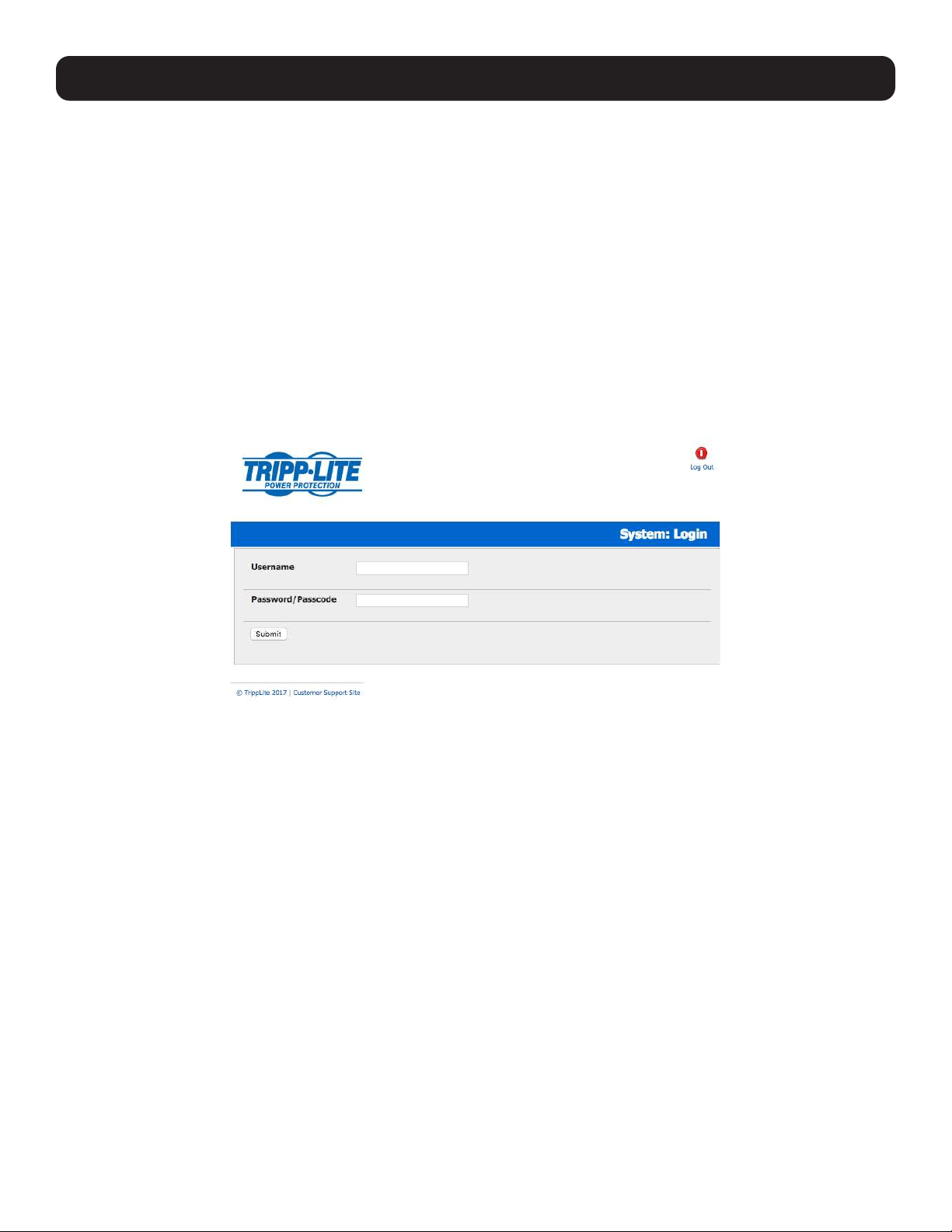
Open a web browser on the connected PC / workstation and enter https://192.168.0.1 . The management console supports
all current versions of popular browsers (Internet Explorer, Mozilla Firefox, Google Chrome, Apple Safari, and more).
Note: Console servers are factory configured with HTTPS access enabled and HTTP access disabled.
A login screen appears. Enter the default administration username root and administration password default.
Note: If you unable to connect to the management console at 192.168.0.1 or if the default Username / Password were not accepted, reset
your console server (refer to 10. Nagios Integration).
Click Submit. The Welcome screen listing the initial installation configuration steps will display. These steps are:
• Change default administration password (see 3.2 Administrator Setup).
Configure the local network settings (see 3.3 Network Configuration).
• To configure console server features:
Configure serial ports settings (see 4. Serial Port, Host, Device and User Configuration).
Configure user port access (see 4. Serial Port, Host, Device and User Configuration).
• If your system has a cellular modem, you will also be provided steps to configure the cellular router features:
Configure the cellular modem connection (see 5. Firewall, Failover & OOB Access).
Allow forwarding to the cellular destination network (see 5. Firewall, Failover & OOB Access).
Enable IP masquerading for cellular connection (see 5. Firewall, Failover & OOB Access).
You can return to the configuration list at any time by clicking the logo in the top left corner of the screen.
14
3. System Configuration
3.2 Administrator Setup
3.2.1 Change Default Root System Password
For security reasons, only the Administrator user named root can initially log into your console server. Also, only users who
know the root password can access and reconfigure the console server.
Since anyone who correctly guesses the root password could gain access (and the default root password is default), it
is essential that you enter and confirm a new password before allow the console serve any access to, or control of, your
computers and network devices.
Select Change default administration password from the Welcome page will take you to Serial & Network: Users &
Groups where you can add a new confirmed Password for the user root.
Note: There are no restrictions on what types of characters can be used in the user password (each can contain up to 254 characters).
However, only the first eight password characters are used to make the password hash.
Note: Because the console server uses flash memory, you will be given the option to save the password across firmware erases. Checking
this will save the password hash in the non-volatile configuration partition, which is not erased on firmware reset. However, take care as if
this password is lost, as the firmware will need to be recovered from the device.
Click Apply. As you have changed the password, you will be prompted to log in again. This time use the new password.
Note: If you are unsure whether your console server is operating with the most current firmware version, Firmware Upgrades are available.
Refer to 11.2 Upgrade Firmware for more information.
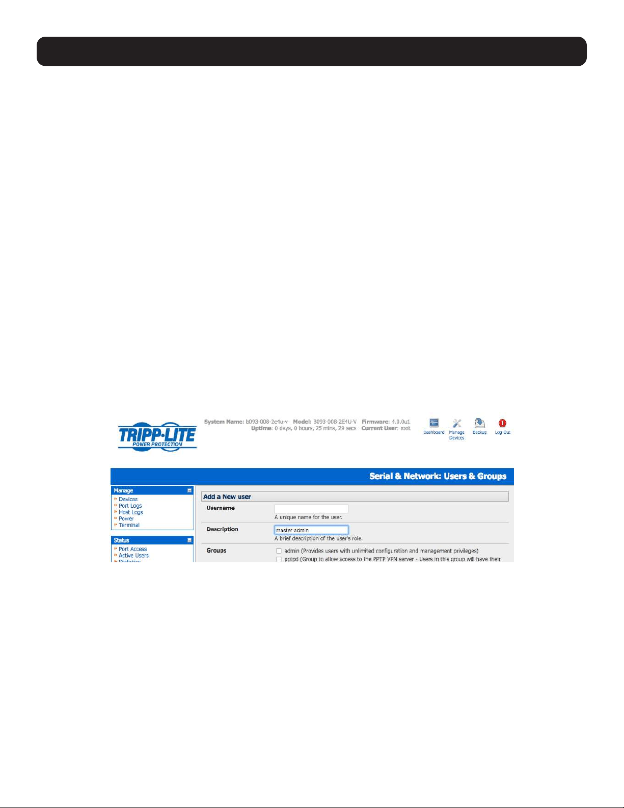
3.2.2 Set Up New Administrator
You should set up a new Administrator user as soon as possible for all ongoing administration functions (rather than root).
This Administrator can be configured in the admin group with full access privileges by selecting Add a New User in the Serial
& Network: Users & Groups menu (refer 4.2 Add and Edit Users).
15
3. System Configuration
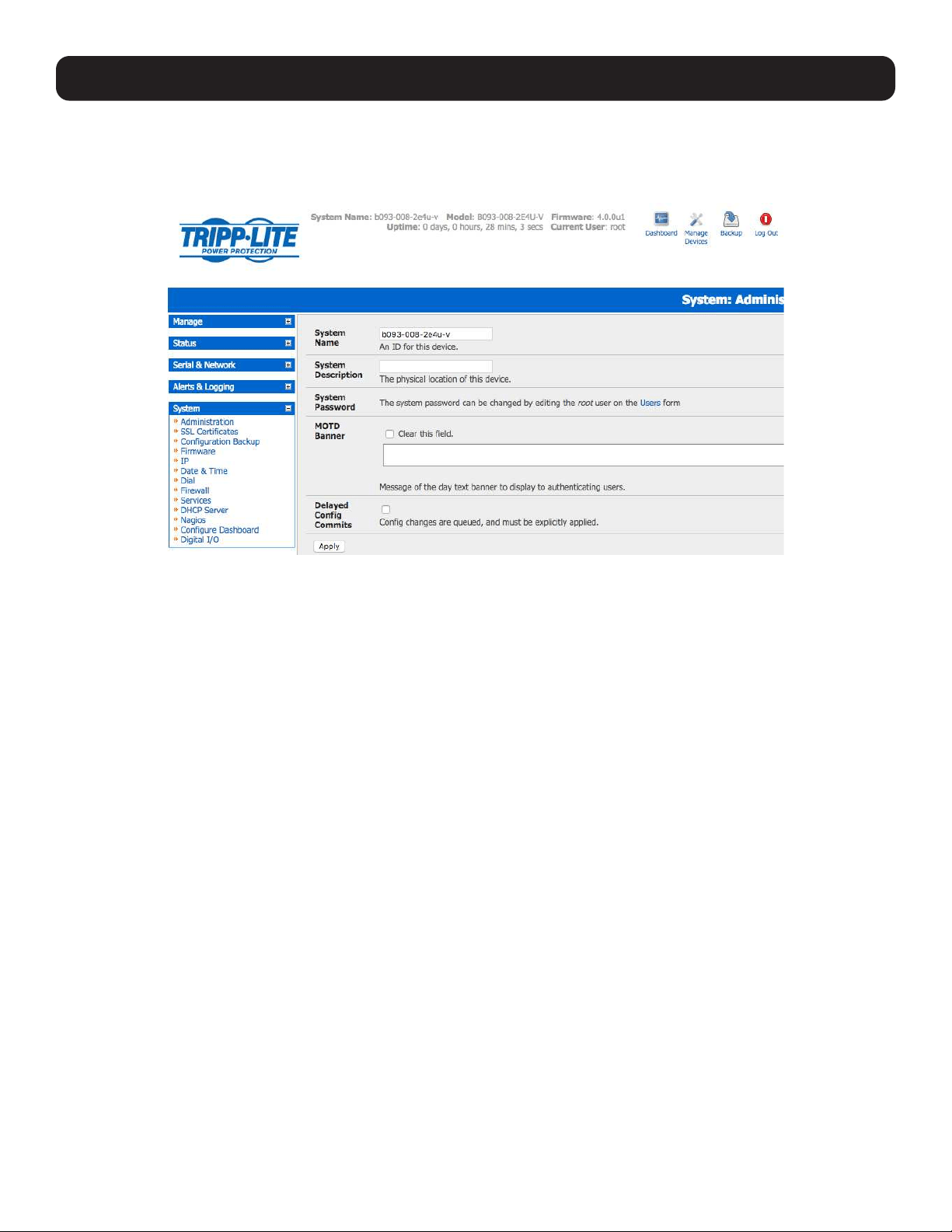
3.2.3 Name the System
Select System: Administration.
Enter a System Name and System Description for the console server to give it a unique ID and make it simple to identify.
Note: The System Name can contain from 1 to 64 alphanumeric characters (you can also use the special characters “-” “_” and “.”). There
are no restrictions on the characters that can be used in the System Description (which can contain up to 254 characters).
The MOTD Banner can be used to display a “message of the day” text to users.
Click Apply.
Note: If you are unsure whether your console server is operating with the most current firmware version, Firmware Upgrades are available.
Refer to 11.2 Upgrade Firmware for more information.
16
3. System Configuration
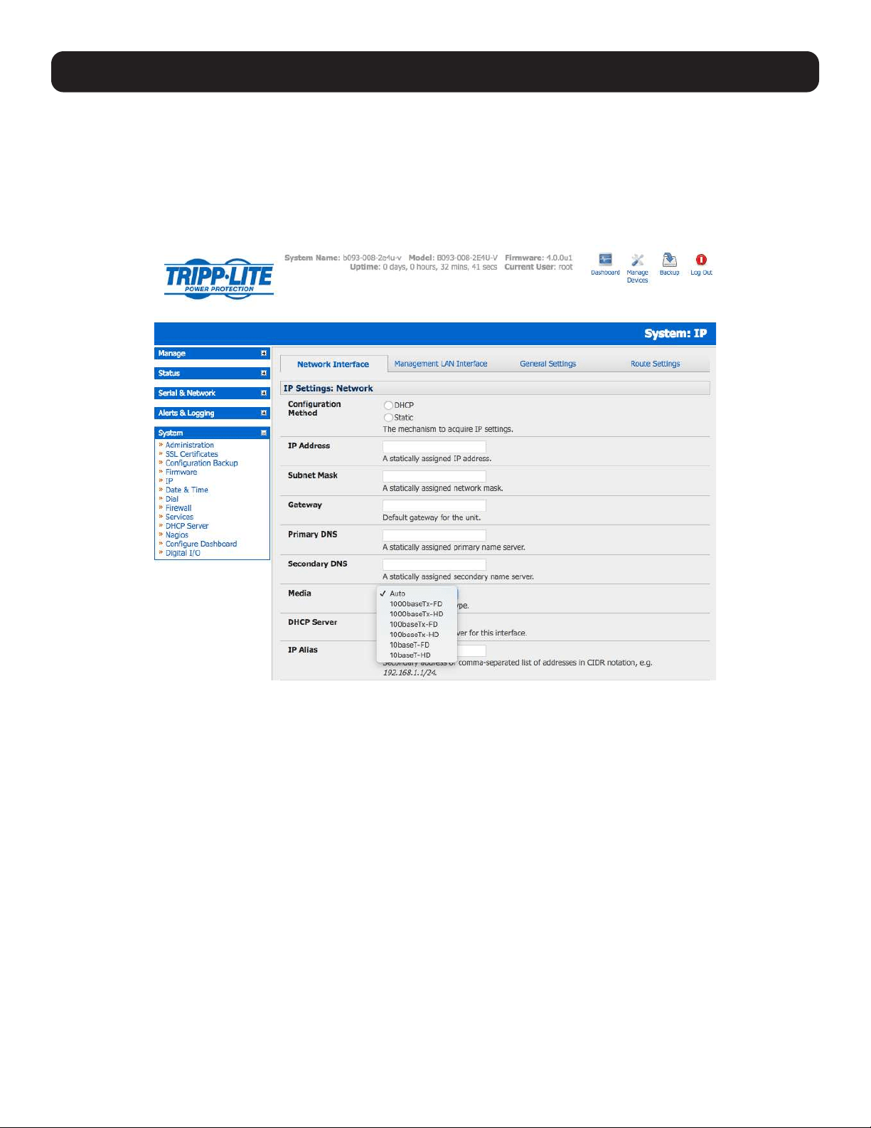
3.3 Network Configuration
Enter an IP address for the principal Ethernet (LAN/Network/Network1) port on the console server, or enable its DHCP client so
that it automatically obtains an IP address from a DHCP server on the network it is to be connected to.
On the System: IP menu, select the Network Interface page, then check DHCP or Static for the Configuration Method.
If you selected Static, you must manually enter the new IP Address, Subnet Mask, Gateway and DNS server details. This
selection automatically disables the DHCP client.
By default, the console server LAN port auto-detects the Ethernet connection speed. However, you can use the Media menu
to lock the Ethernet to 10 Mb/s or 100Mb/s and to Full Duplex (FD) or Half Duplex (HD).
Note: If you encounter packet loss or poor network performance with the default auto-negotiation setting, try manually setting the Ethernet
Media settings on the console server and the device it is connected to. In most cases, select 100baseTx-FD (100 megabits, full duplex).
Make sure both sides are set identically.
If you selected DHCP, the console server will search for configuration details from a DHCP server. This selection automatically
disables any static address. The console server MAC address can be found on a label on the base plate
Note: In its factory default state (with no configuration method selected), the console server has its DHCP client enabled, so it automatically
accepts any network IP address assigned by a DHCP server on your network. In this initial state, the console server will then respond to both
its Static address (192.168.0.1) and its newly assigned DHCP address.
You may also enter a secondary address or comma-separated list of addresses in CIDR notation, e.g. 192.168.1.1/24 as an
IP Alias.
Note: If you have changed the console server IP address, you may need to reconfigure your computer so it has an IP address that is in the
same network range as this new address (as detailed in an earlier note in this section).
Click Apply.
You will need to reconnect the browser on the computer that is connected to the console server by entering
http://new IP address.
17
3. System Configuration
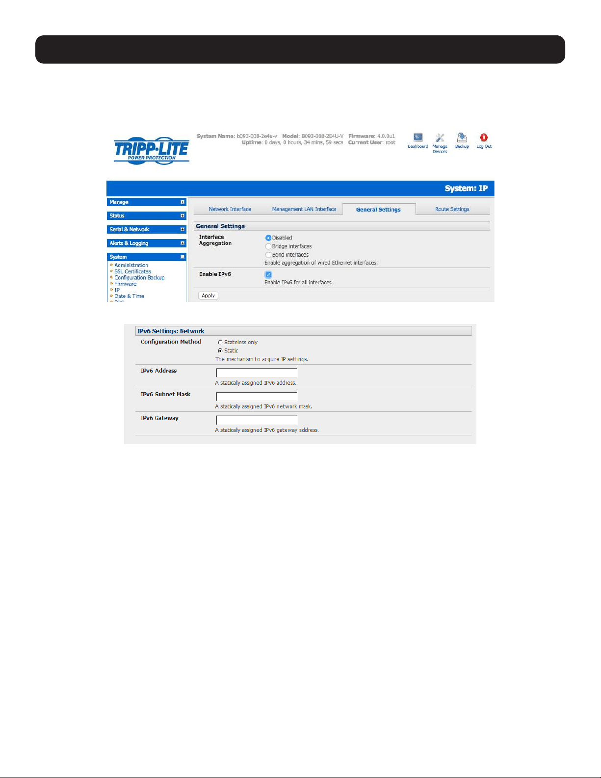
3.3.1 IPv6 Configuration
By default, the console server Ethernet interfaces support IPv4. However, they can also be configured for IPv6 operation:
• On the System: IP menu, select General Settings page and check Enable IPv6.
• You will then need to configure the IPv6 parameters on each interface page.
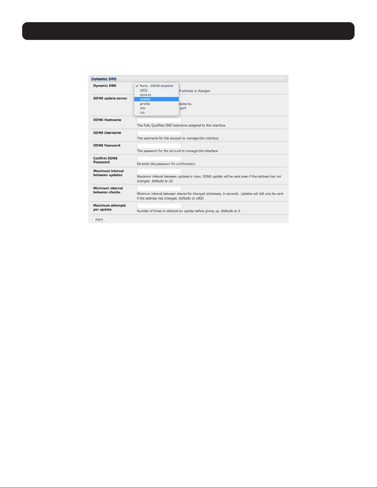
3.3.2 Dynamic DNS (DDNS) Configuration
With Dynamic DNS (DDNS), an advanced console server whose IP address is dynamically assigned (and may change from
time to time) can be located using a fixed host or domain name.
The first step in enabling DDNS is to create an account with the supported DDNS service provider of your choice. Supported
DDNS providers include:
• DyNS www.dyns.cx
• dyndns.org www.dyndns.org
• GNUDip gnudip.cheapnet.net
• ODS www.ods.org
• TZO www.tzo.com
• 3322.org (Chinese provider) www.3322.org
Upon registering with the DDNS service provider, you will select a username and password, as well as a hostname that you will
use as the DNS name (to allow external access to your machine using a URL).
The Dynamic DNS service providers allow the user to choose a hostname URL and set an initial IP address to correspond to
that hostname URL. Many Dynamic DNS providers offer a selection of URL hostnames available for free use with their service.
However, with a paid plan, any URL hostname (including your own registered domain name) can be used.
18
3. System Configuration
You can now enable and configure DDNS on any of the Ethernet or cellular network connections on the console server (by
default DDNS is disabled on all ports):
• Select the DDNS service provider from the dropdown Dynamic DNS list on the System: IP or System: Dial menu.
• In DDNS Hostname, enter the fully qualified DNS hostname for your console server e.g. your-hostname.dyndns.org.
• Enter the DDNS Username and DDNS Password for the DDNS service provider account.
• Specify the Maximum interval between updates (in days). A DDNS update will be sent, even if the address has not
changed.
• Specify the Minimum interval between checks for changed addresses (in seconds). Updates will still only be sent if the
address has changed.
•
Specify the Maximum attempts per update, i.e. the number of times to attempt an update before giving up (defaults to 3).
19
3. System Configuration
3.4 Services and Service Access
The Administrator can access the console server, connected serial ports and managed devices by using a range of access
protocols/services. For each such access:
• The particular service must first be configured and enabled to run on the console server.
• Then, access through the firewall must be enabled for each network connection.
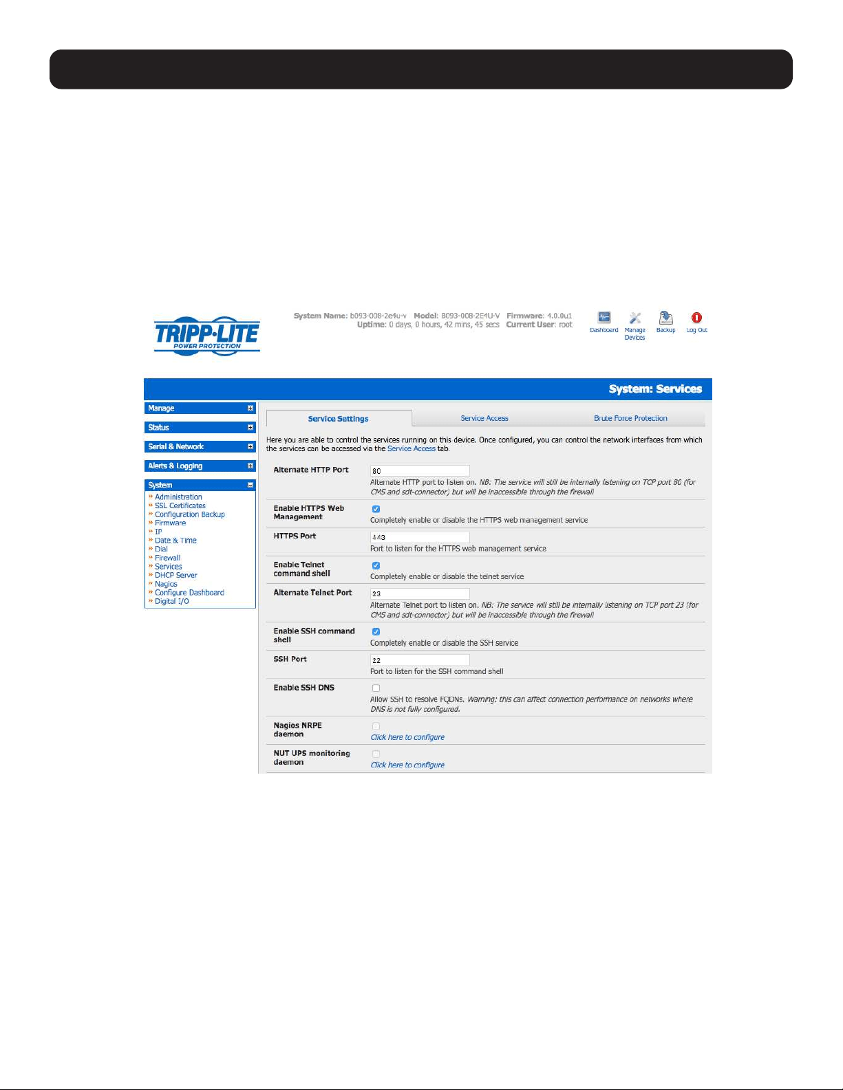
To enable and configure a service:
• Select the Service Settings tab on the System: Services page.
Note: With firmware releases pre-3.5.3, services are enabled and configured using the Service Access tab on the System: Firewall
page.
• Enable and configure basic services:
HTTP By default, the HTTP service is running and cannot be fully disabled. However, by default, HTTP access is disabled
on all interfaces. It is recommended this access remains disabled if the console server is to be remotely accessed
over the Internet.
Alternate HTTP also enables you to configure an alternate HTTP port to listen on. However, the HTTP service will
continue internally listening on TCP port 80 (for CMS and sdt-connector communications), but will be inaccessible
through the firewall.
HTTPS By default, the HTTPS service is running and this service is enabled on all network interfaces. It is recommended
that only HTTPS access be used if the console server is to be managed over any public network (e.g. the Internet).
This ensures the Administrator has secure browser access to all the menus on the console server. It also allows
appropriately configured Users secure browser access to selected Manage menus. For information on certificate and
user client software configuration, refer to section 9. Authentication.
The HTTPS service can be completely disabled (or re-enabled) by checking HTTPS Web Management and an
alternate port specified (default port is 443).

20
Telnet By default, the Telnet service is running. However, by default, the service is disabled on all network interfaces.
Telnet can be used to give the Administrator access to the system command line shell. While this may be suitable
for a local direct connection over a management LAN, it is recommended this service be disabled if the console
server is to be remotely administered. This service may also be useful for local Administrator and User access to
selected serial consoles.
The Enable telnet command shell checkbox will completely enable or disable the telnet service. An alternate
telnet port to listen on can be specified in Alternate Telnet Port (default port is 23).
SSH This service provides secure SSH access to the console server and attached devices. By default, the SSH service is
running and enabled on all interfaces. It is recommended you choose SSH as the protocol where the Administrator
connects to the console server over the Internet or any other public network. This will provide authenticated
communications between the SSH client program on the remote computer and the SSH server in the console
server. For more information on SSH configuration, refer to section 9. Authentication.
The Enable SSH command shell checkbox will completely enable or disable this service. An alternate SSH port to
listen on can be specified in SSH command shell port (default port is 22).
• Enable and configure other services:
TFTP/FTP If a USB flash drive or internal flash memory is detected on a console server, then checking Enable TFTP
(FTP) service will enable this service and set up default tftp and ftp server on the USB flash. These servers
are used to store config files, maintain access and transaction logs, etc. Files transferred using tftp and ftp
will be stored under /var/mnt/storage.usb/tftpboot/ (or /var/mnt/storage.nvlog/tftpboot/ on B093 devices).
Unchecking Enable TFTP (FTP) service will completely disable the TFTP (FTP) service.
DNS Relay Checking Enable DNS Server/Relay will enable the DNS relay feature so clients can be configured with the
console server’s IP for their DNS server setting. The console server will forward the DNS queries to the real
DNS server.
Web Terminal Checking Enable Web Terminal will allow web browser access to the system command line shell via
Manage -> Terminal.
• Specify alternate port numbers for Raw TCP, direct Telnet/SSH and unauthenticated Telnet/SSH services. The console server
uses specific default ranges for the TCP/IP ports for the various access services that Users and Administrators can use to
access devices attached to serial ports (refer to 4.1 Configure Serial Ports for more information). The Administrator can
also set alternate ranges for these services, and these secondary ports will then be used, in addition to the defaults.
The default TCP/IP base port address for telnet access is 2000, and the range for telnet is IP Address: Port (2000 + serial
port #) i.e. 2001 – 2048. So if the Administrator were to set 8000 as a secondary base for telnet, then serial port #2 on
the console server can be telnet accessed at IP Address:2002 and at IP Address:8002. The default base for SSH is 3000;
for Raw TCP is 4000; and for RFC2217 it is 5000
• A number of other services can be enabled and configured indirectly from this menu by selecting Click here to configure:
Nagios Access to the Nagios NRPE monitoring daemons (refer to 8. Power, Environment & Digital I/O).
NUT Access to the NUT UPS monitoring daemon (refer to 10. Nagios Integration).
SNMP This will enable netsnmp in the console server. SNMP is disabled by default (refer to 7. Alerts, Auto-Response
and Logging and 15.5 SNMP Status Reporting).
NTP Refer to 11. System Management.
• Click Apply. As you apply your services selections, the screen will be updated with a confirmation message: Message
Changes to configuration succeeded.
3. System Configuration
21
3. System Configuration
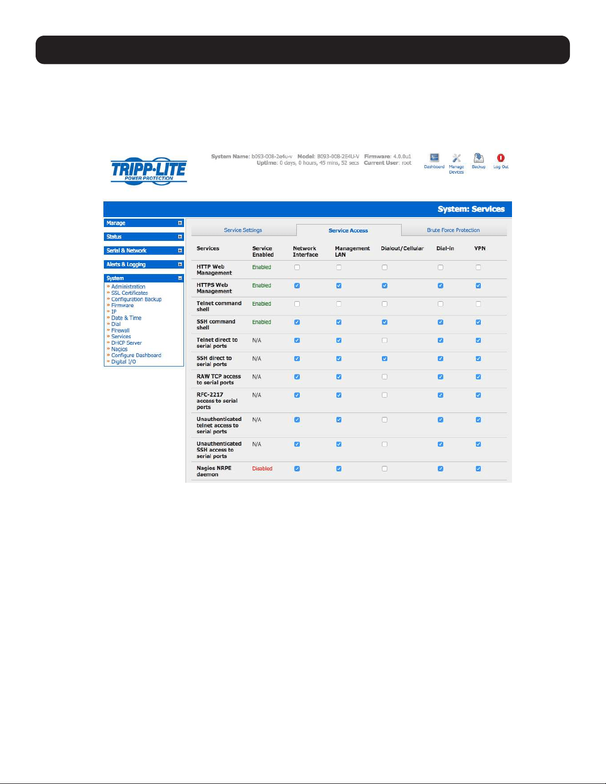
The Services Access settings can now be set to allow or block access. This specifies which (enabled) services the Administrator
can use over each network interface - to connect to the console server and through the console server to attached serial and
network-connected devices.
• Select the Service Access tab on the System: Services page.
Note: With firmware releases pre-3.5.3, the Service Access tab is found on the System: Firewall page.
• This will display the services currently enabled for the console server’s network interfaces. Depending on the particular
console server model, the interfaces displayed may include:
• Network interface (for the principal Ethernet connection)
• Management LAN / OOB Failover (second Ethernet connections)
• Dial-out/Cellular (V90 and 3G modem)
• Dial-in (internal or external V90 modem)
• VPN (IPsec or Open VPN connection over any network interface)
• Check/uncheck for each network which service access is to be enabled /disabled.
22
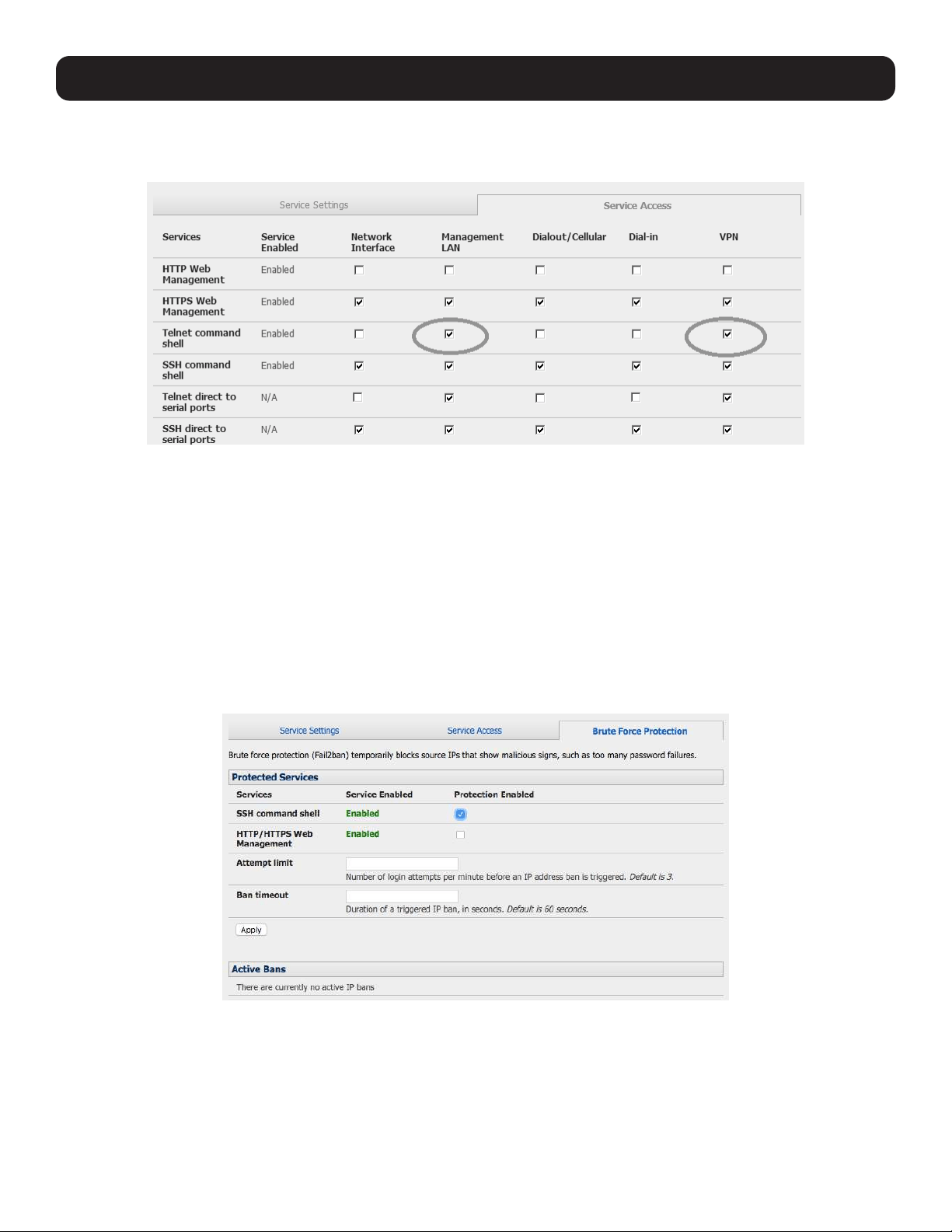
• In the example shown below, local administrators on local Management LAN have direct telnet access to the console server
(and attached serial ports), while remote administrators using dial-in or cellular have no such telnet access (unless they set
up a VPN).
• Respond to ICMP echoes (i.e. ping) Service access options can be configured at this stage. This allows the console server
to respond to incoming ICMP echo requests. Ping is enabled by default. However for security reasons, this service should
generally be disabled post-initial configuration.
• You can also configure to allow serial port devices to be accessed from assigned network interfaces using Raw TCP, direct
Telnet/SSH, unauthenticated Telnet/SSH services, etc.
• Click Apply to apply your services access selections.
3.4.1 Brute Force Protection
Brute force protection (Micro Fail2ban) temporarily blocks source IPs that show malicious signs, such as too many password
failures. This may help mitigate scenarios where the Tripp Lite device’s network services are exposed to an untrusted network
such as the public WAN, and scripted attacks or software worms are attempting to guess (brute force) user credentials and
gain unauthorized access.
Brute Force Protection may be enabled for the listed services. Once protection is enabled, three or more failed connection
attempts within 60 seconds from a specific source IP trigger it to be banned from connecting for the next 60 seconds. Active
Bans are also listed and may be refreshed by reloading the page.
Note: When a Tripp Lite device is running on an untrusted network, it is recommended that a variety of strategies be used to lock down
remote access. This includes strong passwords (or even better, SSH public key authentication), VPN, and using Firewall Rules to whitelist
remote access from trusted source networks only. Refer to the Knowledge Base for details.
3. System Configuration
23
3. System Configuration
3.5 Communications Software
You have configured access protocols for the Administrator client to use when connecting to the console server. User clients
(who you may set up later) will also use these protocols when accessing console server serial attached devices and network
attached hosts. Therefore, you will need to have appropriate communications software tools set up on the Administrator
(and User) client’s computer. Tripp Lite provides the SDT Connector as the recommended client software tool. However, other
generic tools such as PuTTY and SSHTerm may be used.
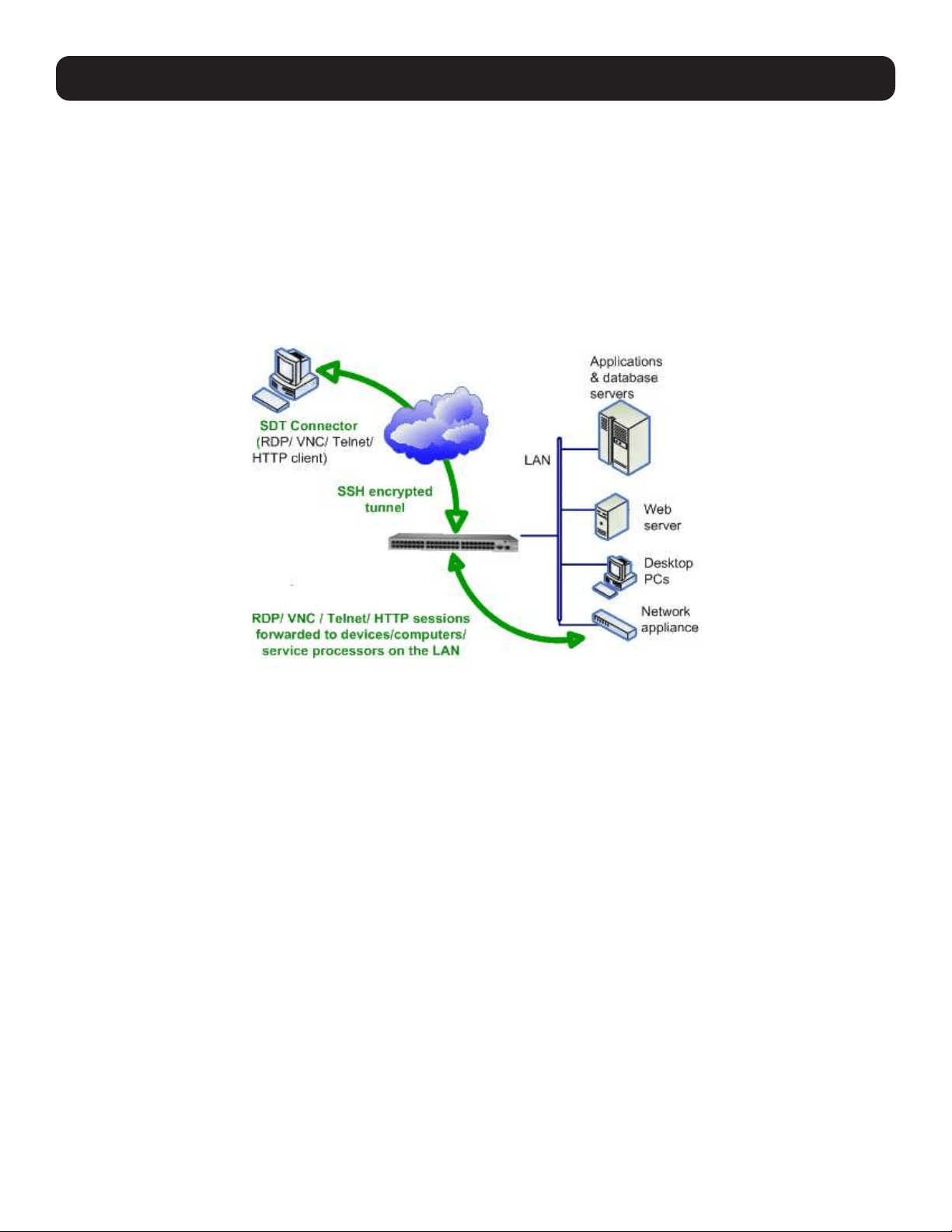
3.5.1 SDT Connector
SDT Connector is a lightweight tool that enables Users and Administrators to securely access the Console server and the
various computers, network devices and devices that may be serially- or network- connected to the console server.
SDT Connector is a Java client program that couples the trusted SSH tunneling protocol with popular access tools such as
telnet, SSH, HTTP, HTTPS, VNC, RDP to provide point-and-click secure remote management access to all systems and devices
being managed.
Information on using SDT Connector for browser access to the console server’s management console, telnet/SSH access to
the console server command line, and TCP/UDP connecting to hosts that are network-connected to the console server can be
found in section 6. Secure Tunneling.
SDT Connector can be installed on Windows PCs, Mac OS and on most Linux, UNIX and Solaris systems.
24
3. System Configuration
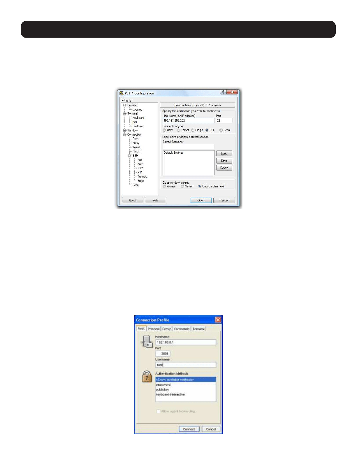
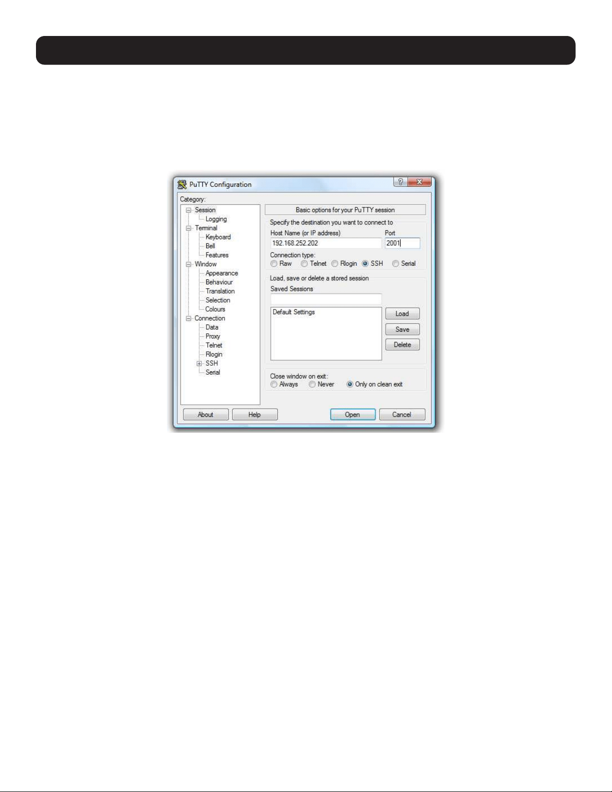
3.5.2 PuTTY
Communications packages like PuTTY can also be used to connect to the console server command line (and to connect
serially attached devices, refer to 4. Serial Port, Host, Device and User Configuration). PuTTY is a freeware implementation
of telnet and SSH for Win32 and UNIX platforms. It runs as an executable application without needing to be installed onto your
system. PuTTY (the telnet and SSH client itself) can be downloaded at http://www.tucows.com/preview/195286.html.
To use PuTTY for an SSH terminal session from a Windows client, enter the console server’s IP address as the “Host Name (or
IP address)”.
To access the console server command line, select SSH as the protocol, and use the default IP Port 22.
Click Open. You will be presented with the console server login prompt. You may also receive a security alert stating the host’s
key is not cached. If this is the case, choose yes to continue.
Using the telnet protocol is similarly simple, except you use the default port 23.
3.5.3 SSHTerm
Another common communications package that may be useful is SSHTerm, an open source package that can be downloaded
from http://sourceforge.net/projects/sshtools:
To use SSHTerm for an SSH terminal session from a Windows Client, simply select the File option and click on New
Connection.
25
3. System Configuration
A new Connection Profile dialog box will appear where you can type in the host name or IP address (for the console server
unit) and the TCP port that the SSH session will use (port 22). Type in your username, choose password authentication and
click Connect.
You may receive a message about the host key fingerprint, and you will need to select Yes or Always to continue.
The next step is password authentication, where a prompt will appear asking for your username and password from the remote
system to log on to the console server.
3.6 Management Network Configuration
Select console servers have additional network ports that can be configured to provide management LAN access and/or
failover or out-of-band access.
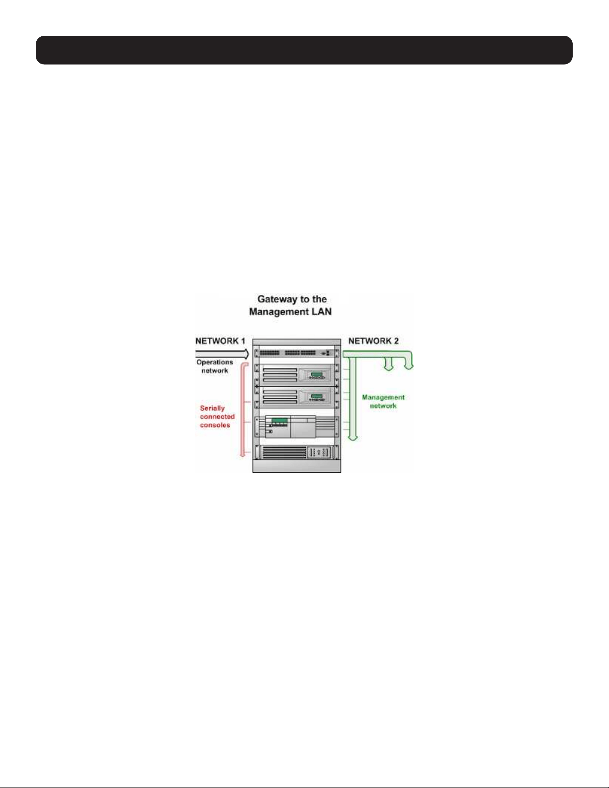
3.6.1 Enable the Management LAN
The console servers can be configured so the second Ethernet port provides a management LAN gateway. The gateway has
firewall, router and DHCP server features. However, you will need to connect an external LAN switch to Network/LAN 2 to
attach hosts to this management LAN:
Note: The second Ethernet port (Network/LAN2) on the console server can be configured as either a Management LAN gateway port or an
OOB/Failover port—it cannot be both. As such, ensure you did not allocate Network/LAN 2 as the Failover Interface when you configured the
principal Network connection on the System: IP menu.
26
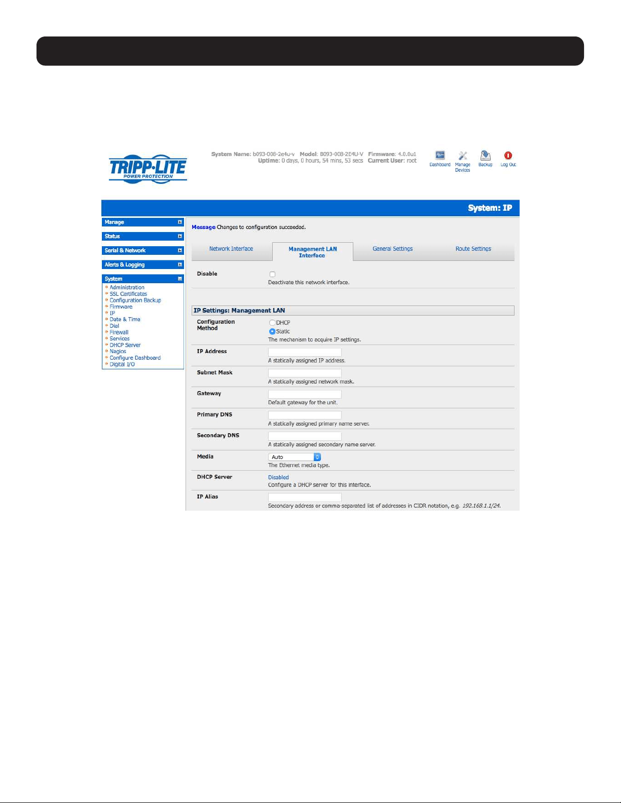
The Management LAN features are all disabled by default. To configure the Management LAN gateway:
• Select the Management LAN Interface page on the System: IP menu and uncheck Disable.
• Configure the IP Address and Subnet Mask for the Management LAN (but leave the DNS fields blank).
• Click Apply.
The management gateway function is now enabled with default firewall and router rules. By default, these rules are configured
so the Management LAN can only be accessed by SSH port forwarding. This ensures the remote and local connections to
managed devices on the Management LAN are secure. The LAN ports can also be configured in bridged or bonded mode (as
described later in this section) or they can be manually configured from the command line.
3. System Configuration
27
3. System Configuration
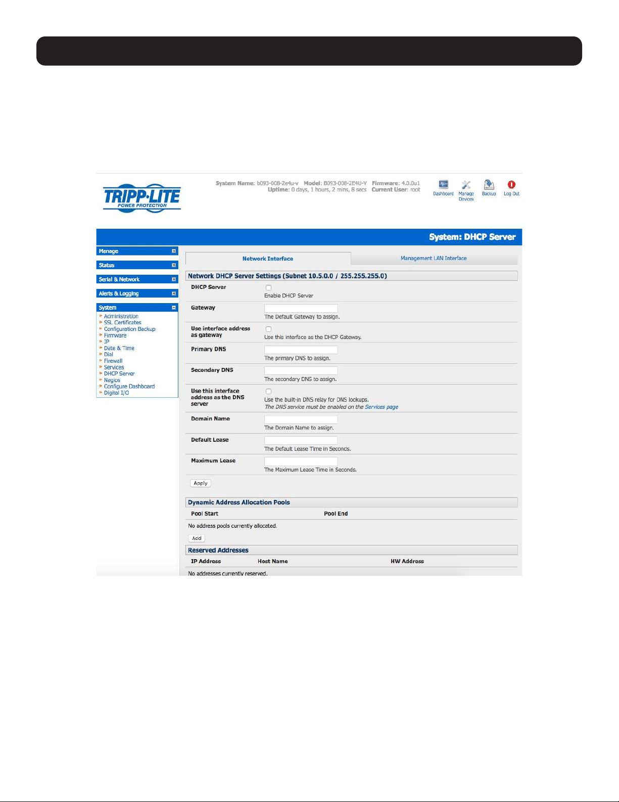
3.6.2 Configure the DHCP Server
All Tripp Lite devices host a DHCP server. However, this setting is disabled by default. The DHCP server enables the automatic
distribution of IP addresses to devices on the Management LAN that are running DHCP clients. To enable the DHCP server:
• On the System: IP menu, select the Management LAN page and click the Disabled label in the DHCP Server field (or go
directly to the System: DHCP Server menu).
• Check Enable DHCP Server.
• Enter the Gateway address that is to be issued to the DHCP clients. If this field is left blank, the console server’s IP address
will be used.
• Enter the Primary DNS and Secondary DNS address to issue the DHCP clients. If this field is left blank, the console
server’s IP address is used. Leave this field blank for automatic DNS server assignment.
• Optionally enter a Domain Name suffix to issue DHCP clients.
• Enter the Default Lease time and Maximum Lease time (in seconds). The lease time is the time that a dynamically
assigned IP address is valid before the client must request it again.
• Click Apply.
28
3. System Configuration
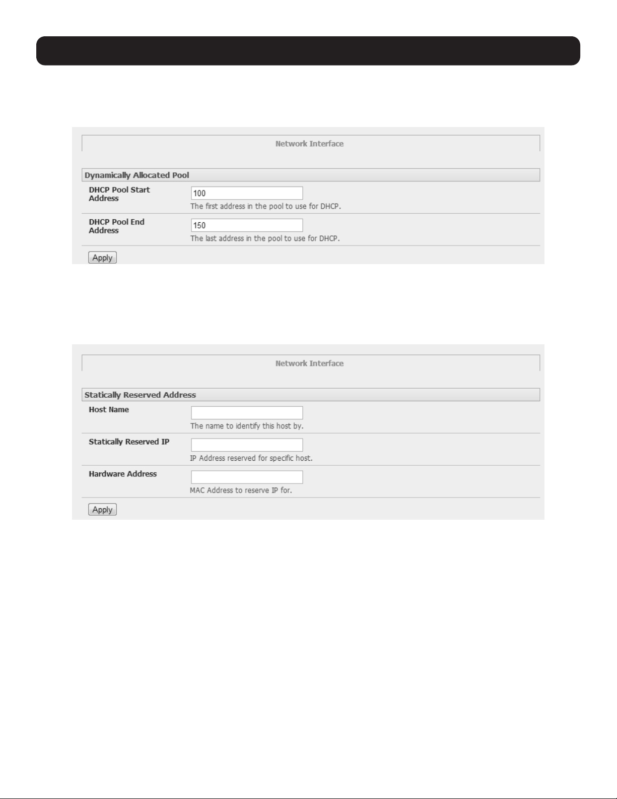
The DHCP server will sequentially issue IP addresses from a specified address pool(s):
• Click Add in the Dynamic Address Allocation Pools field.
• Enter the DHCP Pool Start Address and End Address, then click Apply.
The DHCP server also supports pre-assigning IP addresses to be allocated only to specific MAC addresses and reserving IP
addresses to be used by connected hosts with fixed IP addresses. To reserve IP addresses for a particular host:
• Click Add in the Reserved Addresses field.
• Enter the Hostname, the Hardware Address (MAC) and the Statically Reserved IP address for the DHCP client, then
click Apply.
When DHCP has initially allocated hosts’ addresses, it is recommended to copy these into the pre-assigned list so the same IP
address will be reallocated in the event of a reboot.
29
3. System Configuration
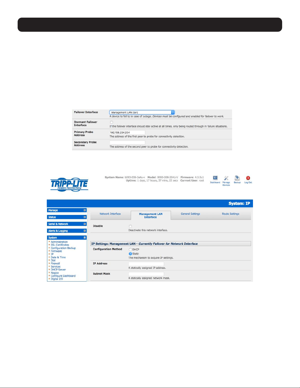
3.6.3 Select Failover or Broadband OOB
The B093 and B098 console servers provide a failover option. In the event a problem arises while using the main LAN
connection for accessing the console server, an alternate access path is automatically used.
By default, the failover is not enabled. To enable:
• Select the Network page on the System: IP menu.
• Now select the Failover Interface to be used in the event of an outage on the main network. This can be:
o A second Ethernet connection on the console server.
o The console server’s internal modem.
o An external modem device connected to the console server.
• Click Apply. You have selected the failover method. However, it is not active until you have specified the external sites to
be probed to trigger failover and set up the failover ports themselves. For more information, refer to section 5. Firewall,
Failover and OOB Access.
Note: The second Ethernet port on the console server can be configured as either a Management LAN gateway port or it can be configured
as an OOB/Failover port, but not both. Ensure you did not configure this port as the Management LAN on the System: IP menu.
30
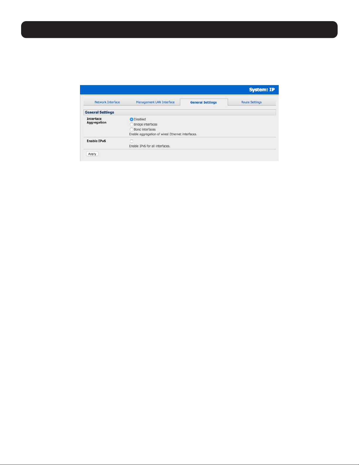
3.6.4 Aggregating the Network Ports
By default, the console server’s Management LAN network ports can only be accessed using SSH tunneling /port forwarding or
by establishing an IPsec VPN tunnel to the console server.
However, all wired network ports on the console servers can be aggregated by being bridged or bonded.
By default, Interface Aggregation is disabled on the System: IP General Settings menu.
Select Bridge Interfaces or Bond Interfaces
• When bridging is enabled, network traffic is forwarded across all Ethernet ports with no firewall restrictions. All the Ethernet
ports are transparently connected at the data link layer (layer 2), so they do retain their unique MAC addresses.
• With bonding, the network traffic is carried between the ports but they present with one MAC address.
• Both modes remove all Management LAN Interface and Out-of-Band/Failover Interface functions and disable the DHCP
Server.
In aggregation mode, all Ethernet ports are configured collectively using the Network Interface menu.
3. System Configuration
31
3. System Configuration
3.6.5 Static Routes
Firmware 3.4 and later support static routes, which provide a quick way to route data from one subnet to a different subnet.
You can hard code a path that specifies to the console server/router to get to a certain subnet by using a certain path.
This may be useful for remotely accessing various subnets at a remote site when being accessed using the cellular OOB
connection.
To add to the static route to the system’s route table:
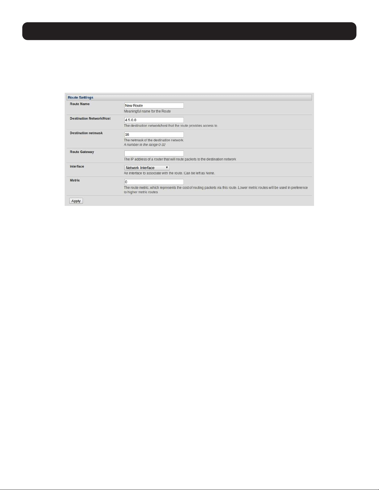
• Select the Route Settings tab on the System: IP General Settings menu.
• Enter a meaningful Route Name for the route.
• In the Destination Network/Host field, enter the IP address of the destination network/host that the route provides access
to.
• Enter a value in the Destination netmask field that identifies the destination network or host. Any number between 0 and
32 can be used. A subnet mask of 32 identifies a host route.
• Enter Route Gateway with the IP address of a router that will route packets to the destination network. This field may be
left blank.
• Select the Interface to use to reach the destination. This field may be left as None.
• Enter a value in the Metric field that represents the metric of this connection. This generally has to be set only if two or
more routes conflict or have overlapping targets. Any number equal to or greater than 0.
• Click Apply.
Note: The route details page provides a list of network interfaces and modems to which a route can be bound. In the case of a modem, the
route will be attached to any dial-up session, which is established via that device. A route can be specified with a gateway, an interface or
both. If the specified interface is not active for whatever reason, then the routes configured for that interface will not be active.
3.7 Configuration over DHCP (ZTP)
Configuration-over-DHCP is available for all Tripp Lite console managers running firmware release 3.16 or later. With this
feature, Tripp Lite devices can be provisioned during their initial boot from a DHCP server. Provisioning on untrusted networks
can be facilitated by providing keys on a USB flash drive.
Preparation
The typical steps for configuration over a trusted network are:
• Manually configure a same-model Tripp Lite device.
• Save its configuration as a backup (.opg) file.
• Select System > Configuration Backup > Remote Backup.
• Click Save Backup.

32
A backup configuration file — model-name_iso-format-date_config.opg — is downloaded from the Tripp Lite device to the
local system.
Alternately, you can save the configuration as an xml file:
• Select System > Configuration Backup > XML Configuration.
An editable field containing the configuration file in XML format is presented.
• Click into the field to make it active.
• If you are running any browser on Windows or Linux, right-click and choose Select All from the contextual menu or press
Control-A. Then, right-click and choose Copy from the contextual menu or press Control-C.
• If you are using any browser on Mac OS, choose Edit > Select All or press Command-A. Then choose Edit > Copy or
press Command-C.
• In your preferred text-editor, create a new empty document, paste the copied data into the empty document and save the
file. Whatever file-name you choose, it must include the.xml filename suffix.
• Copy the saved .opg or .xml file to a public-facing directory on a file server serving at least one of the following protocols:
HTTPS, HTTP, FTP or TFTP (only HTTPS can be used if the connection between the file server and a to-be-configured Tripp
Lite device travels over an untrusted network).
• Configure your DHCP server to include a vendor-specific option for Tripp Lite devices (this will be performed in a DHCP server-
specific way). The vendor-specific option should be set to a string containing the URL of the published .opg or .xml file in the
step above. The option string must not exceed 250 characters and it must end in either .opg or .xml.
• Connect a new Tripp Lite device (either factory-reset or Config-Erased) to the network and apply power.
Note: It may take up to 5 minutes for the device to find the .opg or .xml file (via DHCP), download, install and then reboot.
Example ISC DHCP (dhcpd) Server Configuration
The following is an example DHCP server configuration fragment for serving an .opg configuration image via the ISC DHCP
server, dhcpd:
option space tripp-lite code width 1 length width 1;
option tripp-lite.config-url code 1 = text;
class “ tripp-lite -config-over-dhcp-test” {
match if option vendor-class-identifier ~~ “^Tripp Lite/”;
vendor-option-space tripp-lite;
option tripp-lite.config-url “https://example.com/tripp-lite/${class}.opg”;
}
Setup When the LAN is Untrusted
If the connection between the file server and a to-be-configured Tripp Lite device includes an untrusted network, a two-handed
approach can mitigate the issue.
Note: This approach adds two physical steps where trust can be difficult, if not impossible, to establish completely. First, the custody chain
from the creation of the data-carrying USB flash drive to its deployment. Second, the hands connecting the USB flash drive to the Tripp Lite
device.
• Generate an X.509 certificate for the Tripp Lite device.
• Concatenate the certificate and its private key into a single file named client.pem.
• Copy client.pem onto a USB flash drive.
• Set up an HTTPS server such that access to the .opg or .xml file is restricted to clients that can provide the X.509 client
certificate generated above.
• Put a copy of the CA cert that signed the HTTP server’s certificate — ca-bundle.crt — onto the USB flash drive bearing
client.pem.
• Insert the USB flash drive into the Tripp Lite device before attaching power or network.
• Continue the procedure from ‘Copy the saved .opg or .xml file to a public-facing directory on a file server’ above using the
HTTPS protocol between the client and server.
3. System Configuration

33
3. System Configuration
Prepare a USB Drive and Create the X.509 Certificate and Private Key
• Generate the CA certificate so the client and server Certificate Signing Requests (CSRs) can be signed.
# cp /etc/ssl/openssl.cnf .
# mkdir -p exampleCA/newcerts
# echo 00 > exampleCA/serial
# echo 00 > exampleCA/crlnumber
# touch exampleCA/index.txt
# openssl genrsa -out ca.key 8192
# openssl req -new -x509 -days 3650 -key ca.key -out demoCA/cacert.pem \
-subj /CN=ExampleCA
# cp demoCA/cacert.pem ca-bundle.crt
Note: This procedure generates a certificate called ExampleCA, but any allowed certificate name can be used. Also, this procedure uses
openssl ca. If your organization has an enterprise-wide, secure CA generation process, that should be used instead.
• Generate the server certificate.
# openssl genrsa -out server.key 4096
# openssl req -new -key server.key -out server.csr -subj /CN=demo.example.com
# openssl ca -days 365 -in server.csr -out server.crt \
-keyfile ca.key -policy policy_anything -batch -notext
Note: The hostname or IP address must be the same string as will be used in the serving URL. In the example above, the hostname is
demo.example.com.
• Generate the client certificate.
# openssl genrsa -out client.key 4096
# openssl req -new -key client.key -out client.csr -subj /CN=ExampleClient
# openssl ca -days 365 -in client.csr -out client.crt \
-keyfile ca.key -policy policy_anything -batch -notext
# cat client.key client.crt > client.pem
• Format a USB flash drive as a single FAT32 volume.
• Move the client.pem and ca-bundle.crt files onto the flash drive’s root directory.
34
4. Serial Port, Host, Device and User Configuration
The console server enables access and control of serially attached devices and network-attached devices (hosts). The
Administrator must configure access privileges for each of these devices, and specify the services that can be used to control
the devices. The Administrator can also set up new users and specify each user’s individual access and control privileges.
4.1 Configure Serial Ports
The first step in configuring a serial port is to set the Common Settings, such as the protocols and the RS-232 parameters
that are to be used for the data connection to that port (e.g. baud rate).
Then you select what mode the port is to operate in. Each port can be set to support one of these operating modes:
i. Disabled mode is the default. The serial port is inactive.
ii. Console Server mode enables general access to serial console port on the serially attached devices.
iii. Device mode sets the serial port up to communicate with an intelligent serial controlled PDU, UPS or Environmental
Monitor Devices (EMD).
iv. SDT mode enables graphical console access (with RDP, VNC, HTTPS etc.) to hosts that are serially connected.
v. Terminal Server mode sets the serial port to await an incoming terminal login session.
vi. Serial Bridge mode enables the transparent interconnection of two serial port devices over a network.
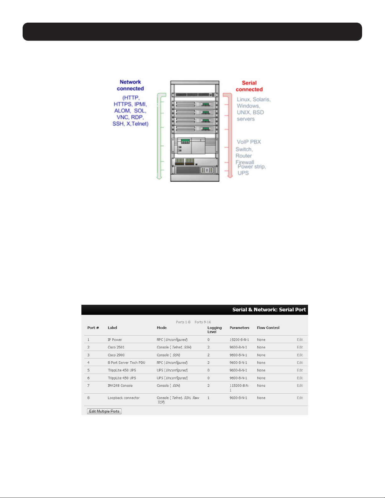
Select Serial & Network: Serial Port to see details of the serial ports currently set up.
By default, each serial port is set in Console Server mode. To reconfigure the port, click Edit.
When you have reconfigured the common settings (see 4.1.1 Common Settings) and the mode (see sections 4.1.2 - 4.1.6)
for each port, set up any remote syslog (see 4.1.7 Syslog), then click Apply.
Note: If you wish to set the same protocol options for multiple serial ports at once, click Edit Multiple Ports and select which ports you wish
to configure as a group.
35
If the console server has been configured with distributed Nagios monitoring enabled, then you will also be presented with
Nagios Settings options to enable assigned services on the Host to be monitored (see section 10. Nagios Integration for
more information).
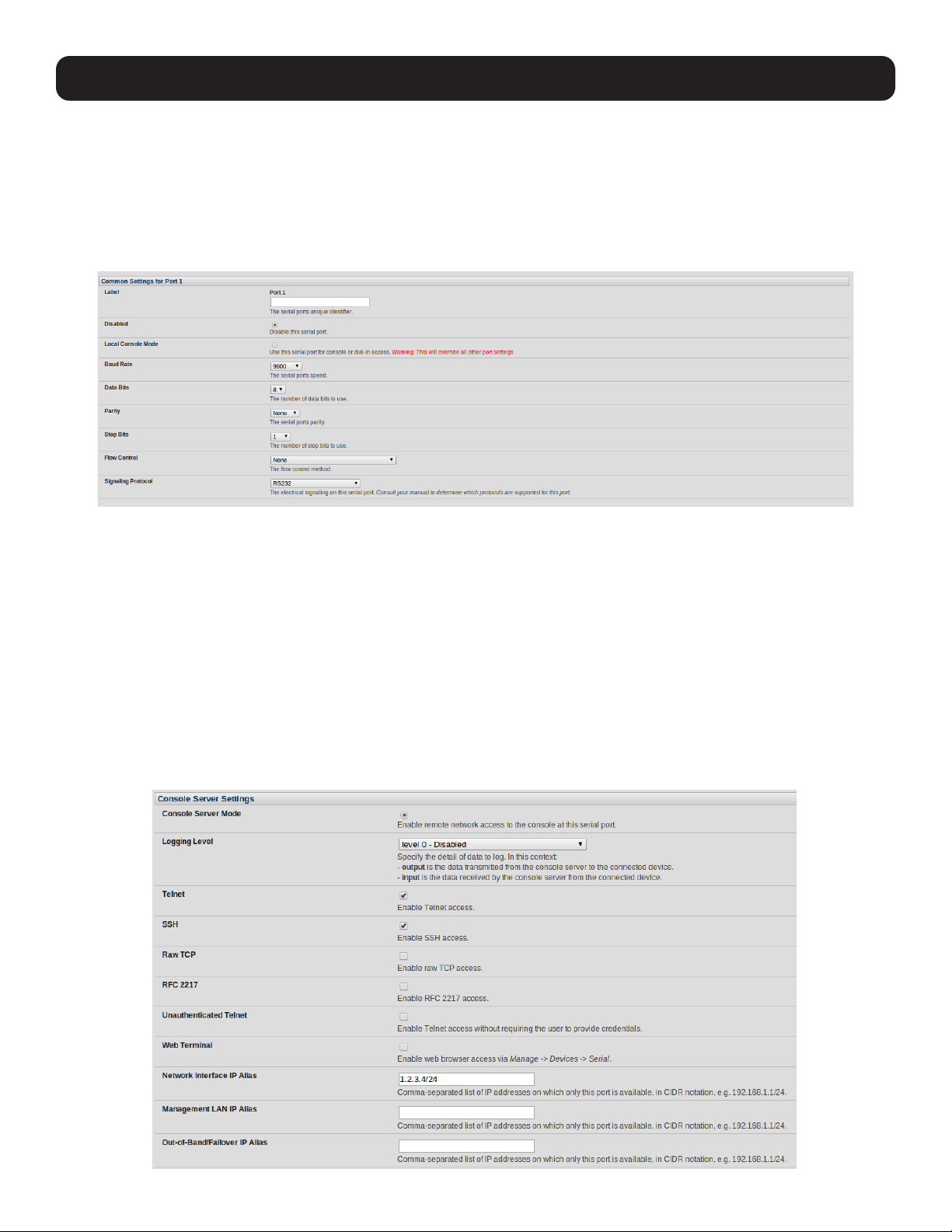
4.1.1 Common Settings
There are a number of common settings for each serial port. These are independent of the mode in which the port is being
used. These serial port parameters must be set so they match the serial port parameters on the device you attach to that port:
• Specify a label for the port.
• Select the appropriate Baud Rate, Parity, Data Bits, Stop Bits and Flow Control for each port.
• Set the Signaling Protocol. This menu item only presents in ports with RS422/485 options. The options available are RS-
232, RS-422, RS-485 and RS-485 Echo mode.
• Set the Port Pin-Out. This menu item is only for ports where pin-out for each RJ45 serial port can be set as either X2 (Cisco
Straight) or X1 (Cisco Rolled).
• Before proceeding with further serial port configuration, you should connect the ports to the serial devices they will be
controlling and ensure they have matching settings.
4.1.2 Console Server Mode
• Select Console Server Mode to enable remote management access to the serial console that is attached to this serial
port:
4. Serial Port, Host, Device and User Configuration
36
4. Serial Port, Host, Device and User Configuration
Logging Level This specifies the level of information to be logged and monitored (refer to 7. Alerts and Logging).
Telnet When the telnet service is enabled on the console server, a telnet client on a User’s or Administrator’s
computer can connect to a serial device attached to this serial port on the console server. The telnet
communications are unencrypted so this protocol is generally recommended only for local or VPN tunneled
connections.
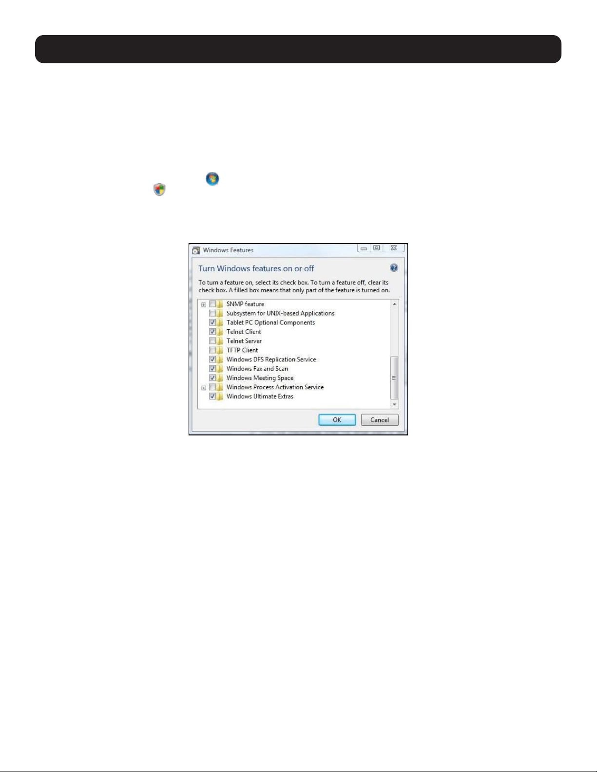
With Win2000/XP/NT, you can run telnet from the command prompt (cmd.exe). Windows Vista and later ships
with a telnet client but it is not enabled by default. You can install it by following the simple steps below.
o Click the Start button , click Control Panel, click Programs, and then click Turn Windows Features
On or Off . If you are prompted for an administrator password or confirmation, type the password or
provide confirmation.
o In the Windows Features dialog box, select the Telnet Client check box.
o Click OK. The installation might take several minutes.
If remote communications are being tunneled with SDT Connector, then telnet can be used for securely
accessing these attached devices.
Note: In Console Server mode, Users and Administrators can use SDT Connector to set up secure telnet connections that are SSH tunneled
from their client computers to the serial port on the console server. The SDT Connector can be installed on Windows PCs and on most Linux
platforms. It enables secure telnet connections to be selected with a simple point-and-click.
To use SDT Connector to access consoles on the console server serial ports, configure the SDT Connector with the console
server as a gateway, then as a host. Then enable telnet service on Port (2000 + serial port #) i.e. 2001–2048. Refer to 6.
SSH Tunnels and SDT Connector for more details on using the SDT Connector for telnet and SSH access to devices that are
attached to the console server serial ports.
37
You can also use standard communications packages like PuTTY to set a direct telnet (or SSH) connection to the serial ports.
Note: PuTTY also supports telnet (and SSH). The procedure to set up a telnet session is simple. Enter the console server’s IP address as the
‘Host Name (or IP address)’. Select Telnet as the protocol and set the TCP port to 2000, plus the physical serial port number (i.e. 2001
to 2048).
Click the Open button. You may receive a security alert stating the host’s key is not cached. If this is the case, you will need to choose yes
to continue. You will then be presented with the login prompt of the remote system connected to the serial port chosen on the console
server. You can login as normal and use the host serial console screen.
PuTTY can be downloaded at http://www.tucows.com/preview/195286.html
Note: In Console Server mode, when you connect to a serial port, you connect via pmshell. To generate a BREAK on the serial port, type the
character sequence ~b. If doing this over OpenSSH, type ~~b.
SSH It is recommended you use SSH as the protocol where the User or Administrator connects to the console server (or
connects through the console server to the attached serial consoles) over the Internet or any other public network. This
will provide authenticated SSH communications between the SSH client program on the remote user’s computer and
the console server, so the user’s communication with the serial device attached to the console server is secure.
For SSH access to the consoles on devices attached to the console server serial ports, you can use SDT Connector.
You configure SDT Connector with the console server as a gateway, then as a host, and you enable SSH service on Port
(3000 + serial port #) i.e. 3001-3048.
You can also use common communications packages like PuTTY or SSHTerm to SSH connect directly to port address IP
Address _ Port (3000 + serial port #) i.e. 3001–3048.
Alternately, SSH connections can be configured using the standard SSH port 22. The serial port being accessed is then
identified by appending a descriptor to the username. This syntax supports:
<username>:<portXX>
<username>:<port label>
<username>:<ttySX>
<username>:<serial>
For example, in order for a User named “Fred” to access serial port 2, when setting up the SSHTerm or the PuTTY SSH
client, instead of typing username = fred and ssh port = 3002, the alternate is to type username = fred:port02
(or username = fred:ttyS1) and ssh port = 22.
4. Serial Port, Host, Device and User Configuration
38
4. Serial Port, Host, Device and User Configuration
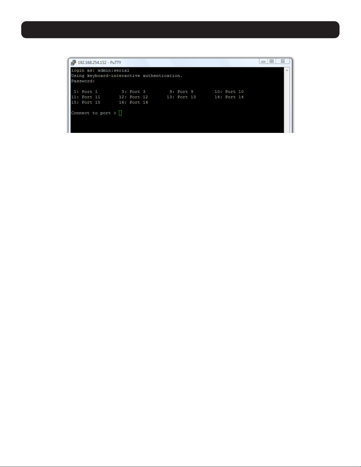
Or, by typing username=fred:serial and ssh port = 22, the User is presented with a port selection option:
This syntax enables Users to set up SSH tunnels to all serial ports with only a single IP port 22 having to be opened in
their firewall/gateway
Note: In Console Server mode, when you connect to a serial port, you connect via pmshell. To generate a BREAK on the serial port, type the
character sequence ~b. If connecting over OpenSSH, type ~~b.
TCP RAW TCP allows connections directly to a TCP socket. However, while communications programs like
PuTTY also supports RAW TCP, this protocol would usually be used by a custom application.
For RAW TCP, the default port address is IP Address _ Port (4000 + serial port #) i.e. 4001 – 4048.
RAW TCP also enables the serial port to be tunneled to a remote console server, so two serial port
devices can be transparently interconnect over a network (refer to section 4.1.6 Serial Bridging).
RFC2217 Selecting RFC2217 enables serial port redirection on that port. For RFC2217, the default port
address is IP Address _ Port (5000 + serial port #) i.e. 5001 – 5048.
RFC2217 also enables the serial port to be tunneled to a remote console server, so two serial port
devices can be transparently interconnect over a network (refer to section 4.1.6 Serial Bridging).
Unauthenticated Telnet Selecting Unauthenticated Telnet enables telnet access to the serial port without authentication
credentials. When a user accesses the console server to telnet to a serial port, they are normally
provided a login prompt. However, with unauthenticated telnet, they connect directly to the port
without any console server login restrictions (if a telnet client does prompt for authentication, any
entered data will allow connection).
This mode is mainly used when you have an external system (such as conserver) to manage user
authentication and access privileges at the serial device level.
NB: only the connection to the console server is unauthenticated. Logging into a device connected
to the console server may still require authentication.
For Unauthenticated telnet, the default port address is IP Address _ Port (6000 + serial port #)
i.e. 6001 – 6048.
Unauthenticated SSH Selecting Unauthenticated SSH enables SSH access to the serial port without authentication
credentials. When a user accesses the console server to telnet to a serial port, they are normally
provided a login prompt. However, with unauthenticated SSH, they connect directly to the port
without any console server login challenge (if a SSH client does prompt for authentication, any
entered data will allow connection).
This mode is primarily used when you have another system managing user authentication and
access privileges at the serial device level, but still wish to encrypt the session across the network.
NB: only the connection to the console server is unauthenticated. Logging into a device connected
to the console server may still require authentication.
For Unauthenticated telnet, the default port address is IP Address _ Port (7000 + serial port #)
i.e. 7001 – 7048.
Note: The <username>: method of port access (as described in the above SSH section) always requires
authentication.

39
4. Serial Port, Host, Device and User Configuration
Web Terminal Selecting Web Terminal enables web browser access to the serial port via Manage: Devices:
Serial using the management console’s built in AJAX terminal. Web Terminal connects as the
currently authenticated management console user and does not re-authenticate. See section 13.3
Terminal Connection for details.
IP Alias Enable access to the serial port using a specific IP address specified in CIDR format. Each serial
port can be assigned one or more IP aliases, configured on a per-network-interface basis.
For example, a serial port can be made accessible at both 192.168.0.148 (as part of the internal
network) and 10.10.10.148 (as part of the Management LAN). It is also possible to make a serial
port available on two IP addresses on the same network (e.g., 192.168.0.148 and
192.168.0.248).
These IP addresses can only be used to access the specific serial port using the standard protocol
TCP port numbers of the console server services. For example, SSH on serial port 3 would be
accessible on port 22 of a serial port IP alias (whereas on the console server’s primary address, it is
available on port 2003).
This feature can also be configured from the multiple port edit page. In this case, the IP addresses
are applied sequentially. The first selected port receives the IP address entered, while subsequent
ports receive incremental addresses with numbers being skipped for any ports unselected. For
example, if ports 2, 3 and 5 are selected and the IP alias 10.0.0.1/24 is entered for the network
interface, the following addresses will be assigned:
Port 2: 10.0.0.1/24 Port 3: 10.0.0.2/24 Port 5: 10.0.0.4/24
Accumulation Period By default, once a connection has been established for a particular serial port (such as an RFC2217
redirection or telnet connection to a remote computer), any incoming characters on that port are
forwarded over the network on a character-by-character basis. The accumulation period changes
this by specifying a period of time that incoming characters will be collected before being sent as a
packet over the network.
Escape Character This enables you to change the character used for sending escape characters. The default is ~.
Power Menu This setting enables the shell power command so a user can control the power connection to
a managed device from command line when they are connected to the device via telnet or SSH. To
operate, the managed device must be set up with both its serial port connection and power
connection configured. The command to open the power menu is ~p
Single Connection This setting limits the port to a single connection, so multiple users have access privileges for a
particular port. Only one user at a time can access that port (port “snooping” is not permitted).
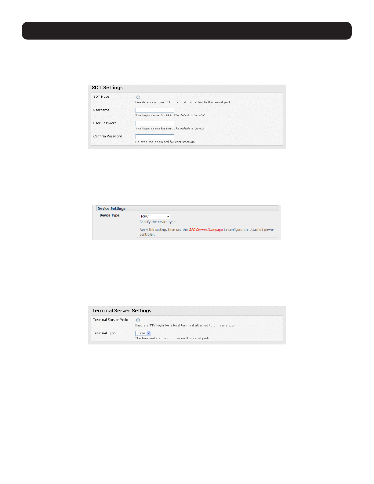
40
4. Serial Port, Host, Device and User Configuration
4.1.3 SDT Mode
This secure tunneling setting allows port forwarding of RDP, VNC, HTPP, HTTPS, SSH, telnet and other LAN protocols to
computers locally connected to the console server by their serial COM port. However, such port forwarding requires a PPP link
to be set up over this serial port.
For configuration details, refer to section 6.4 SDT Connector: Using Telnet or SSH to Connect Devices that are Serially
Attached to the Console Server.
4.1.4 Device (RPC, UPS, EMD) Mode
This mode configures the selected serial port to communicate with a serial-controlled Uninterruptable Power Supply (UPS),
Remote Power Controller / Power Distribution Unit (RPC) or Environmental Monitoring Device (EMD).
Select the desired Device Type (UPS, RPC or EMD).
Proceed to the appropriate device configuration page (Serial & Network: UPS Connections, RPC Connection or
Environmental) as detailed in section 8. Power, Environment and Digital I/O.
4.1.5 Terminal Server Mode
Select Terminal Server Mode and the Terminal Type (vt220, vt102, vt100, Linux or ANSI) to enable a getty on the selected
serial port
The getty will then configure the port and wait for a connection to be made. An active connection on a serial device is usually
indicated by the Data Carrier Detect (DCD) pin on the serial device. When a connection is detected, the getty program issues a
login: prompt, then invokes the login program to handle the actual system login.
Note: Selecting Terminal Server mode will disable Port Manager for that serial port. Data will no longer log for alerts etc.
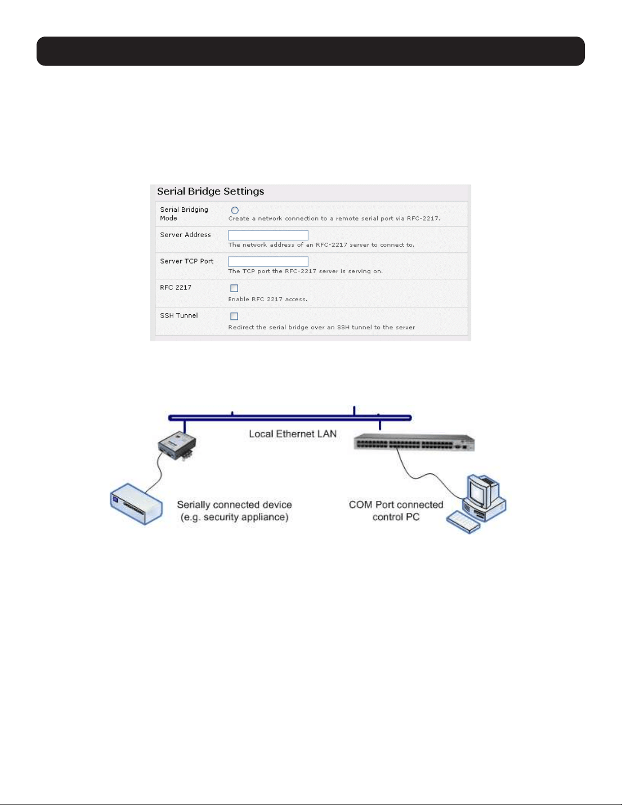
41
4.1.6 Serial Bridging Mode
With serial bridging, the serial data on a console server’s serial port is organized in network packets and transported over
a network to a second console server, effectively allowing the two console servers to act as a virtual serial cable on an IP
network.
One console server is configured to be the Server. The Server serial port to be bridged is set in Console Server mode with
either RFC2217 or RAW enabled (refer to 4.1.2 Console Server Mode).
For the Client console server, the serial port to be bridged must be set in Serial Bridging Mode:
• Select Serial Bridging Mode and specify the IP address of the Server console and the TCP port address of the remote
serial port (for RFC2217 bridging, this will be 5001-5048).
• By default, the bridging client will use RAW TCP. You must select RFC2217 if this is the console server mode you have
specified on the server console.
• You may secure the communications over the local Ethernet by enabling SSH. However, you will need to generate and
upload keys (refer to section 14. Configuration from the Command Line).
4.1.7 Syslog
In addition to built-in logging and monitoring (which can be applied to serial-attached and network-attached management
accesses, as covered in section 7. Alerts, Auto-Response and Logging), the console server can also be configured to
support the remote syslog protocol on a per serial port basis.
Select the Syslog Facility and Syslog Priority fields to enable traffic logging on the syslog server’s selected. Doing so will
appropriately sort and create an action for those logged messages (e.g., redirect or send an alert email).
For example, if the computer attached to serial port 3 should never send anything out on its serial console port, the
Administrator can set the Syslog Facility for that port to local0 (local0 – local7 are meant for site local values), and the Syslog
Priority to critical. At this priority, if the console server syslog server does receive a message, it will automatically create an
alert. See 7. Alerts, Auto-Response and Logging for more information.
4. Serial Port, Host, Device and User Configuration

42
4. Serial Port, Host, Device and User Configuration
4.1.8 USB Consoles
B093, B097, and B098 model console servers running firmware 3.16.5 or later support USB console connections to devices
from a wide range of vendors, including Cisco, HP, Dell and Brocade. All the USB ports on these console servers can also
function as plain RS-232 serial ports when a USB-to-serial adapter is connected.
These USB ports are available as regular port manager ports and are presented numerically in the web UI after all RJ45 serial
ports.
The RJ45 serial ports are presented in Serial & Network > Serial Port.
The common settings (baud rate, etc.) are used when configuring the ports. Some operations (e.g., sending serial breaks) may
not work, depending on the implementation of the underlying USB serial chip.
4.1.9 Link Layer Discovery Protocol (LLDP)
The Link Layer Discovery Protocol (LLDP) is a protocol that allows system administrators to gather information about devices
physically connected to managed switches. It is available for use on B093-Series devices.
The LLDP service is enabled through the System > Services page. When the service is enabled, the lldpd daemon is loaded
and running. The Service Access tab controls which network interfaces are monitored by the lldpd daemon.
When LLDP is granted access to an interface, it will use that interface, even if the interface has been disabled through
System > IP.
LLDP neighbors are visible through the Status > LLDP Neighbors page. This page shows neighbors detected and indicates
the console manager is sending information.
Note: Although the LLDP service can be granted access to non-Ethernet interfaces (for example, G3, G4 and PSTN dial-up interfaces), it
currently ignores non-Ethernet interfaces.
The lldpcli shell client interacts with and configures the running LLDP service.
Persistent custom configuration changes can be added to the system through configuration files placed in /etc/config/lldpd.d/.
Custom configuration files (which must have filenames ending with .conf) will be read and executed by lldpcli when the LLDP
service starts.
The /etc/ directory is read-only on Tripp Lite hardware. Most default configuration files otherwise stored in /etc/ are on Tripp Lite
hardware in /etc/config/, which is writeable.
The default lldpd configuration file lldpd.conf is saved in /etc/config/ on Tripp Lite hardware. It is not safe to save custom
configuration details. There are circumstances in which this file is regenerated automatically, in which case all customizations
will be lost.
The etc/config/lldpd.d/ directory, which is also writable and created on first boot is safe to write to. Any Custom LLDP
configurations must be stored as *.conf files in this directory.
When enabled, LLDP frames issued by a Tripp Lite Console Manager will reveal sensitive information such as hostname and
firmware version.
LLDP frames are not passed through by 802.3ab compliant switches. Tripp Lite Console Managers have the LLDP service
disabled by default.
Both lldpd and lldpcli have standard manual pages but because of space concerns, these pages are not shipped with
Tripp Lite hardware. However, both manual pages are available on the lldpd project: man lldpd can be found at
https:// vincentbernat.github.io/lldpd/usage.html#lldpd8; and man lldpcli can be found at
https:// vincentbernat.github.io/lldpd/usage.html#lldpcli8.
Note: Tripp Lite uses lldpd 0.9.2.
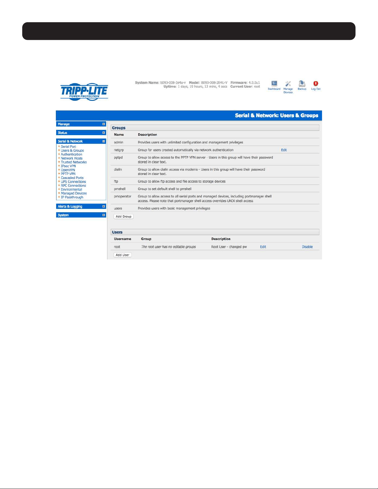
43
4. Serial Port, Host, Device and User Configuration
4.2 Add and Edit Users
The Administrator uses this menu selection to set up, edit and delete users, and define the access permissions for each of
these users.
Users can be authorized to access specified services, serial ports, power devices and specified network-attached hosts. These
users can also be given full Administrator status (with full configuration, management and access privileges).
To simplify user set up, they can be configured as members of Groups. With firmware V3.5.2 and later, there are six Groups
set up by default (earlier versions only had admin and user by default):
admin Provides users with unlimited configuration and management privileges.
pptpd Group to allow access to the PPTP VPN server. Passwords for users in this group are stored in plain text.
dialin Group to allow dial-in access via modems. Passwords for users in this group are stored in plain text.
ftp Group to allow ftp access and file access to storage devices.
pmshell Group to set default shell to pmshell.
users Provides users with basic management privileges.
Notes: 1. The admin group provides the admin user with full Administrator privileges. The admin user (Administrator) can access the
console server using any of the services enabled in System: Services (e.g., if only HTTPS has been enabled, then the
Administrator can only access the console server using HTTPS). However, once logged in, they can reconfigure the console
server settings (e.g., to enabled HTTP/telnet for future access). They can also access any of the connected hosts or serial port
devices using any of the services enabled for these connections. The Administrator can reconfigure the access services for any
host or serial port. Only trusted users should have Administrator access.
2. The user group provides the general user with limited access to the console server, connected hosts and serial devices. These
Users can access only the management section of the Management Console menu with no command line access to the console
server. They also can only access those hosts and serial devices that have been checked for them.
3. If a user is set up with pptd, dialin, ftp or pmshell group membership, they will have restricted user shell access to the
assigned managed devices but will not have any direct access to the console server itself. To add this function, the user must
also be a member of the “users” or “admin” groups.
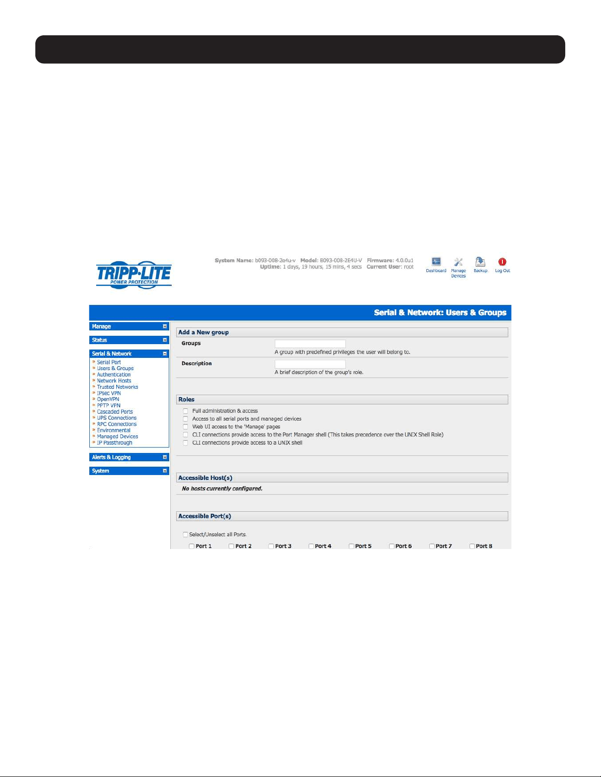
44
4. Serial Port, Host, Device and User Configuration
4. The Administrator can also set up additional groups with permissions to a specific power device, serial port and host access.
However, users in these additional groups do not have any access to the Management Console menu nor do they have any
command line access to the console server itself.
5. The Administrator can also set up users with specific power device, serial port and host access permissions, who are not a
member of any Groups. Similarly, these users do not have any access to the Management Console menu, nor do they have any
command line access to the console server itself.
6. For convenience, the SDT Connector “Retrieve Hosts” function retrieves and autoconfigures checked serial ports and checked
hosts only, even for admin group users.
4.2.1 Set Up New Group
To set up new groups and users, and assign users to particular groups:
• Select Serial & Network: Users & Groups to display the configured Groups and Users.
• Click Add Group to add a new group.
• Add a Group name and Description for each new Group. Then select the Accessible Hosts, Accessible Ports and
Accessible RPC Outlet(s) you wish for users in this new group to be able to access.
• Click Apply.
• The Administrator can Edit or Delete any added group.
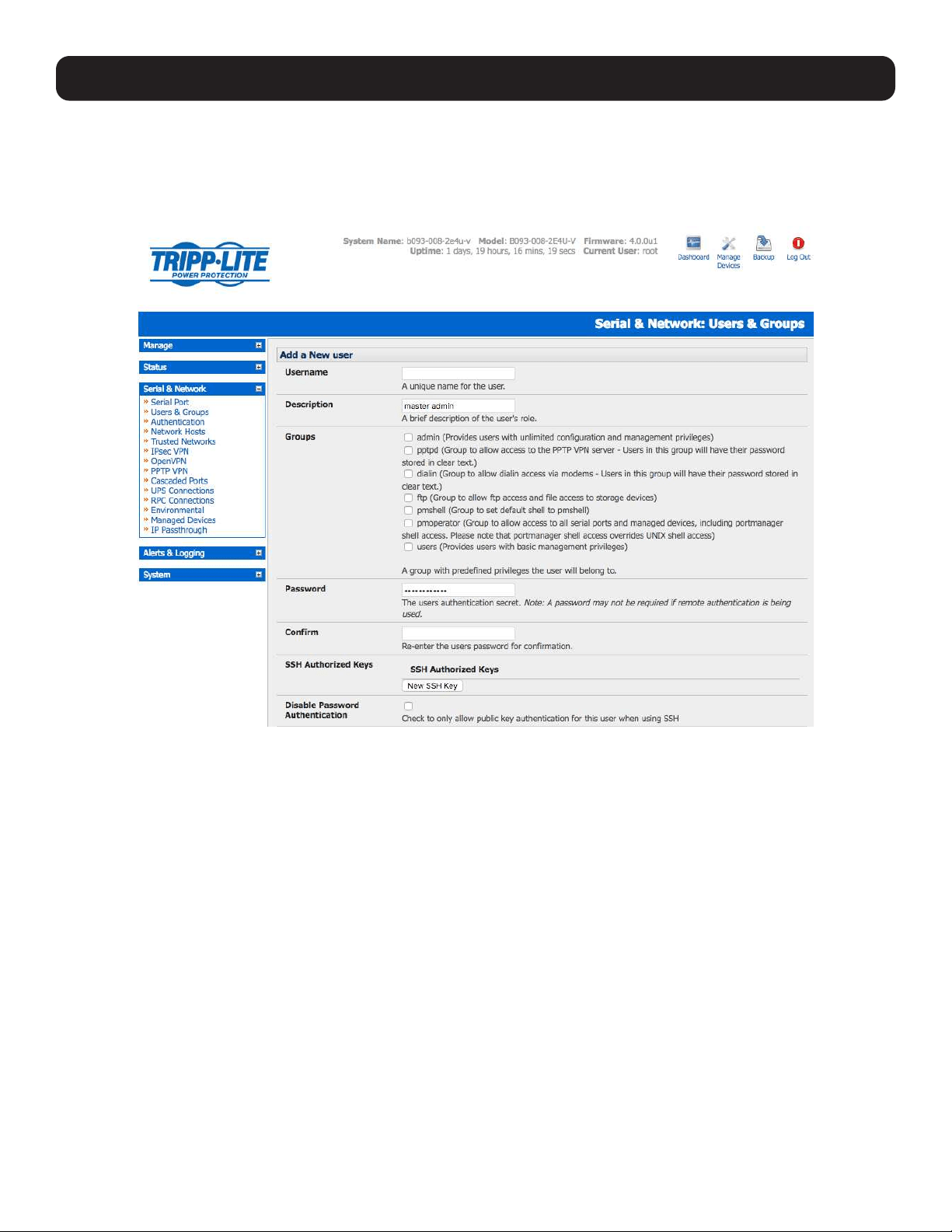
45
4.2.2 Set Up New Users
To set up new users, and assign users to particular groups:
• Select Serial & Network: Users & Groups to display the configured groups and user.
• Click Add User to add a new user.
• Add a Username for each new user. You may also include information related to the user (e.g., contact details) in the
Description field.
Note: The username can contain from 1 to 127 alphanumeric characters (special characters “-” “_” and “.” may also be used).
• Specify which Group (or Groups) you wish to assign the user to.
• Add a confirmed Password for each new user.
Note: There are no restrictions on the characters that can be used for the user’s password (which each can contain up to 254
characters). However, only the first eight password characters are used to make the password hash.
• SSH pass-key authentication can be used. This is more secure than password-based authentication. Paste the public keys
of authorized public/private key pairs for this user in the Authorized SSH Keys field.
• Check Disable Password Authentication if you wish to only allow public key authentication for this user when using SSH.
• Check Enable Dial-Back in the Dial-in Options menu to allow an outgoing dial-back connection to be triggered by logging
into this port. Enter the Dial-Back Phone Number with the phone number to call back when user logs in.
• Check specific Accessible Hosts and/or Accessible Ports to assign the serial ports and network-connected hosts you wish
the user to have access privileges to.
• If there are configured RPCs, you can check Accessible RPC Outlets to specify which outlets the user can control (i.e.
Power On/Off).
• Click Apply. The new user will now be able to access the Network Devices, Ports and RPC Outlets you assigned as
accessible. If the user is a group member, they can also access any other device/port/outlet that was set up as accessible to
that group.
4. Serial Port, Host, Device and User Configuration
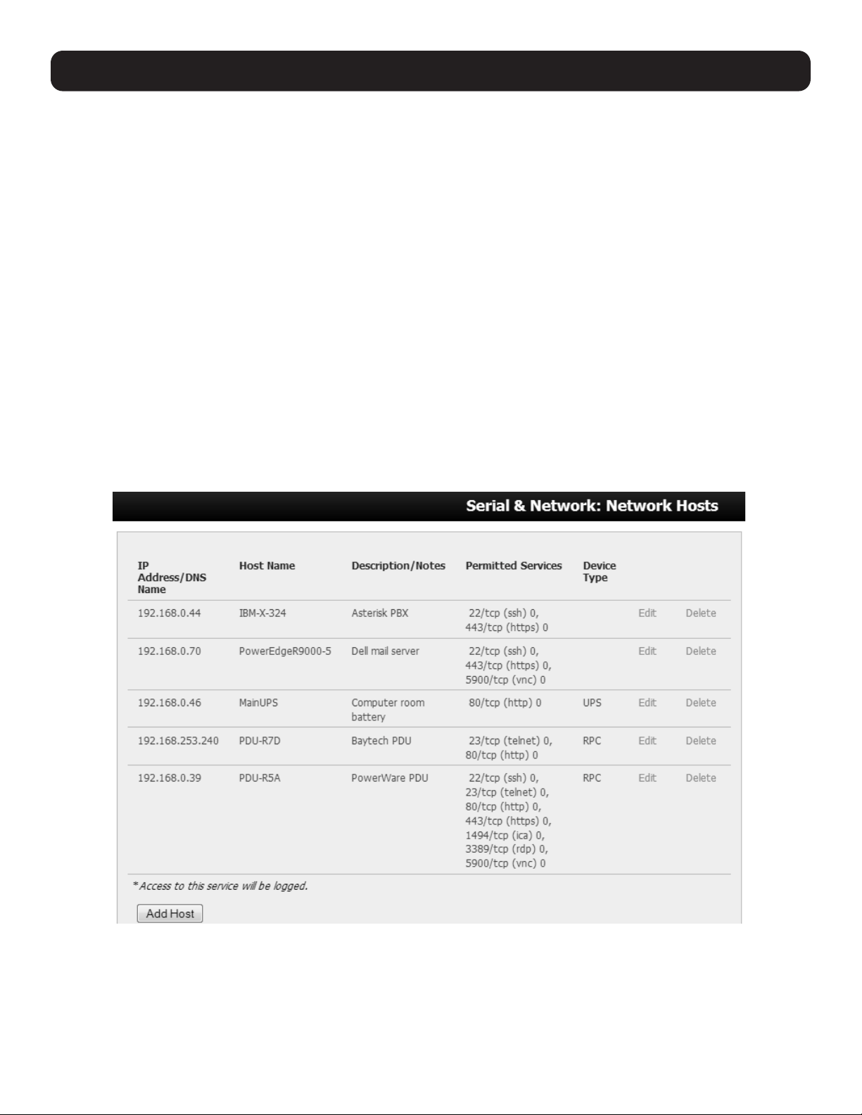
46
4. Serial Port, Host, Device and User Configuration
Note: There are no specific limits on the number of users you can set up, nor on the number of users per serial port or host. Multiple users
(Users and Administrators) can control/monitor the one port or host. Similarly, there are no specific limits on the number of groups. Each
user can be a member of multiple groups (in which case, they assume the cumulative access privileges of each of those groups). A user
does not have to be a member of any groups. If the user is not a member of the default user group, then they will not be able to use the
management console to manage ports.
While there are no specific limits, the time to reconfigure does increase as the number and complexity increases. As such, the recommended
aggregate number of users and groups should be kept under 250.
The Administrator can also edit the access settings for any existing users:
• Select Serial & Network: Users & Groups and click Edit to modify the user access privileges.
• Alternately, click Delete to remove the user or click Disable to temporarily block any access privileges.
Note: For more information on enabling the SDT Connector so each user has secure tunneled remote RPD/VNC/Telnet/HHTP/HTTPS/SoL
access to the network-connected hosts, refer 6. SSH Tunnels and SDT Connector.
4.3 Authentication
Refer to Chapter 9.1 - Remote Authentication Configuration for authentication configuration details.
4.4 Network Hosts
To monitor and remotely access a locally networked computer or device (referred to as a host), you must identify the host and
specify the TCP or UDP ports/services that will be used to control that host:
Selecting Serial & Network: Network Hosts presents all the network-connected hosts that have been enabled for access, as
well as the related access TCP ports/services.
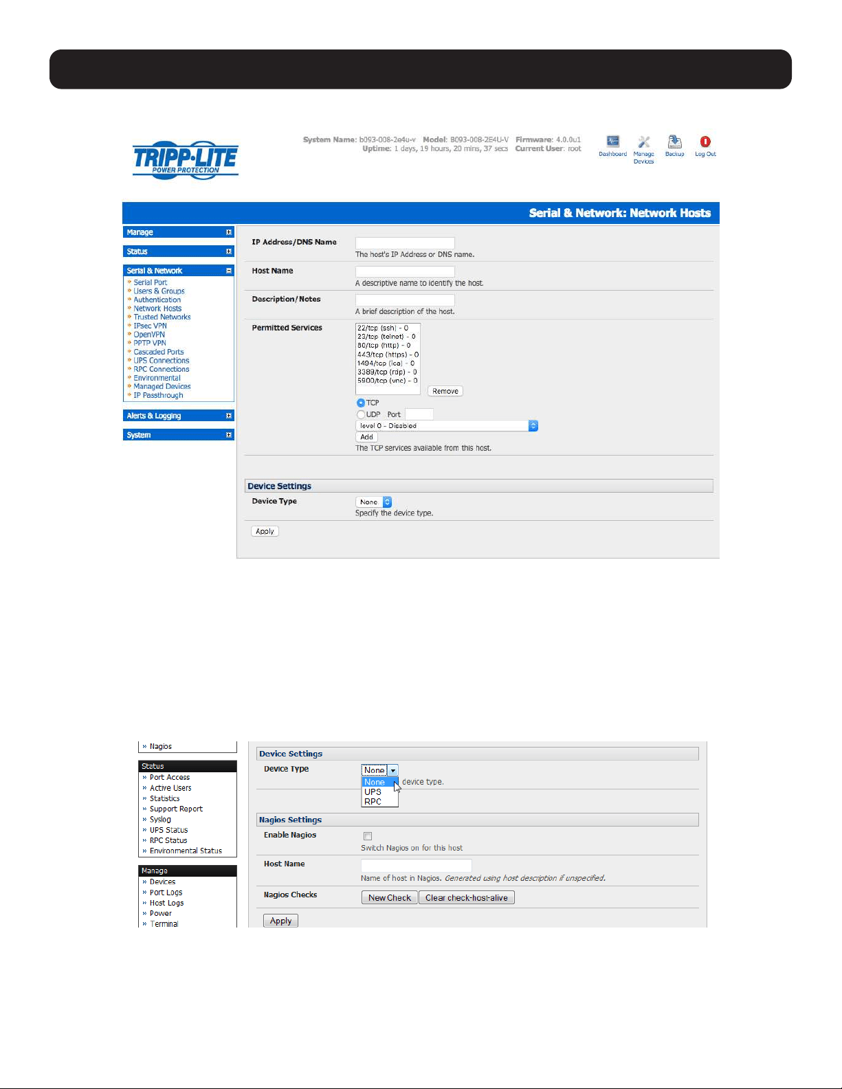
47
Click Add Host to enable access to a new host (or select Edit to update the settings for existing host).
Enter the IP Address or DNS Name and a Host Name (up to 254 alphanumeric characters) for the new network-connected
host. You can optionally enter a Description.
Add or edit the Permitted Services (or TCP/UDP port numbers) authorized for controlling this host. Only these permitted
services will be forwarded by SDT to the host. All other services (TCP/UDP ports) will be blocked.
The Logging Level specifies the level of information to be logged and monitored for each host access (refer to 7. Alerts,
Auto-response and Logging for more information).
If the host is a PDU or UPS power device or a server with IPMI power control, then specify RPC (for IPMI and PDU) or UPS and
the Device Type. The Administrator can then configure these devices and enable which users have permissions to remotely
cycle power etc. (refer to 8. Remote Power Control for more information). Otherwise, leave the Device Type set to None.
If the console server has been configured with distributed Nagios monitoring enabled, you will also be presented with Nagios
Settings options to enable assigned services on the host to be monitored (refer to 10. Nagios Integration).
Click Apply. This will create the new host and create a new managed device with the same name.
4. Serial Port, Host, Device and User Configuration
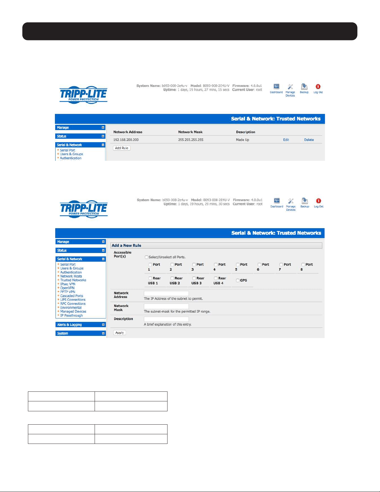
48
4. Serial Port, Host, Device and User Configuration
4.5 Trusted Networks
The Trusted Networks facility provides an option to assign specific IP addresses that users (Administrators and Users) must
be located in order to have access to console server serial ports:
• Select Serial & Network: Trusted Networks.
• To add a new trusted network, select Add Rule.
Note: In the absence of rules, there are no access limitations to the IP address for which Users or Administrators can be located.
• Select the Accessible Port(s) that the new rule is applied to.
• Enter the Network Address of the subnet to be permitted access.
• Specify the range of addresses that are to be permitted by entering a Network Mask for that permitted IP range.
To permit all the users located with a particular Class C network (204.15.5.0 say) connection to the assigned port then you
would add the following Trusted Network New Rule:
Network IP Address 204.15.5.0
Subnet Mask 255.255.255.0
If you want to permit only the one user who is located at a specific IP address (204.15.5.13) to connect:
Network IP Address 204.15.5.13
Subnet Mask 255.255.255.255
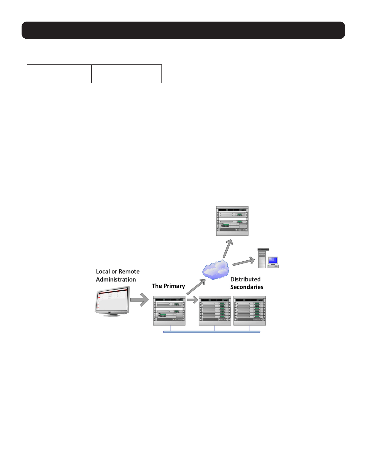
49
4. Serial Port, Host, Device and User Configuration
If you wish to allow all users operating from within a specific range of IP addresses (any of the 30 addresses from
204.15.5.129 to 204.15.5.158) to be permitted connection to the assigned port:
Host /Subnet Address 204.15.5.128
Subnet Mask 255.255.255.224
• Click Apply.
Note: The above trusted networks will limit access by Users and Administrators to the console serial ports. However, they do not restrict
access by the Administrator to the console server itself or to attached hosts. To change the default settings for this access, you will to need
to edit the iptables rules as described in section 14. Configuration from the Command Line.
4.6 Serial Port Cascading
Cascaded Ports enable you to cluster distributed console servers so a large number of serial ports (up to 1000) can be
configured and accessed through one IP address and managed through a single management console. The Primary console
server controls other console servers as Secondary units and all the serial ports on the Secondary units appear as if they are
part of the Primary.
Tripp Lite’s clustering connects each Secondary unit to the Primary unit via SSH connection. This is done using public key
authentication so the Primary unit can access each Secondary unit using the SSH key pair (rather than using passwords). This
ensures secure authenticated communications between Primary and Secondary units, enabling the Secondary units to be
distributed locally on a LAN or remotely.
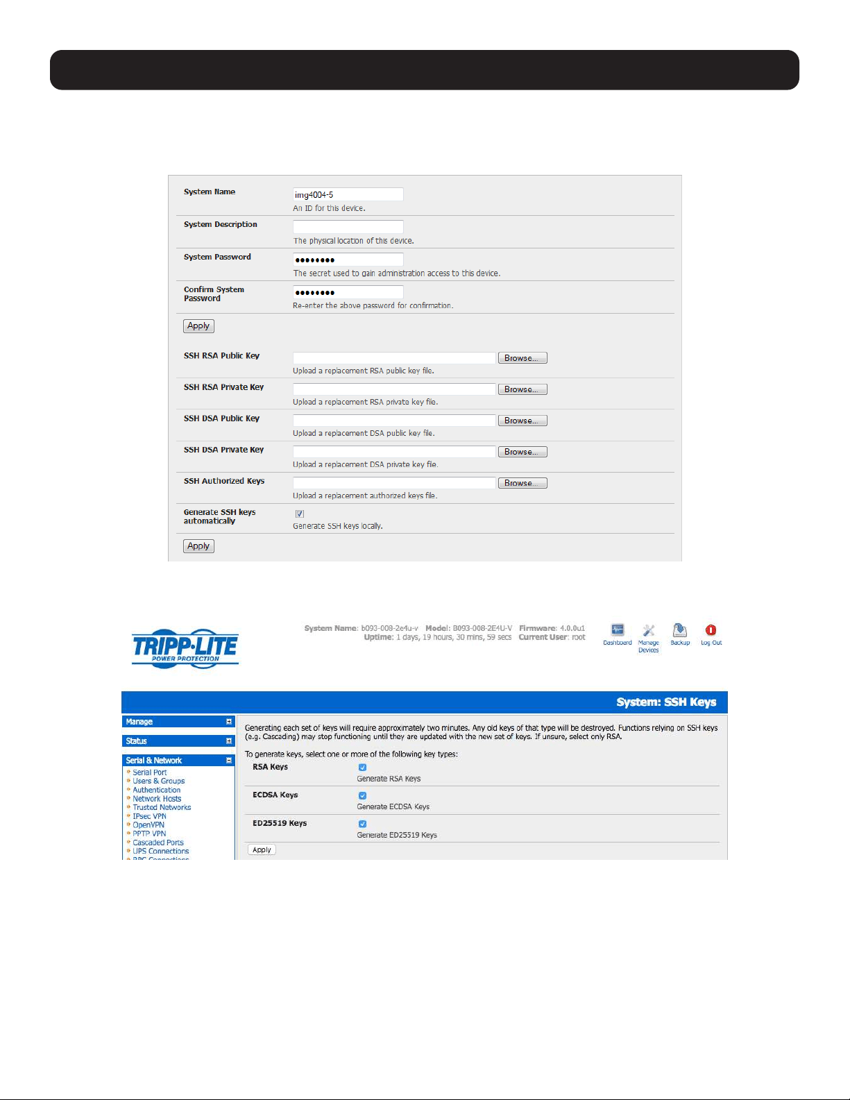
50
4. Serial Port, Host, Device and User Configuration
4.6.1 Automatically Generate and Upload SSH keys
To set up public key authentication, you must first generate an RSA or DSA key pair and upload them into the Primary and
Secondary console servers. This can all be done automatically from the Primary unit:
• Select System: Administration on the Primary unit’s management console.
• Check Generate SSH keys automatically and click Apply.
Next, you must select whether to generate keys using RSA and/or DSA (if unsure, select only RSA). Generating each set of
keys will take approximately two minutes. During this time, the new keys will destroy any old keys that may previously been
uploaded. Also, relying on SSH keys (e.g., cascading) may stop functioning until they are updated with the new set of keys. To
generate keys:
• Select RSA Keys and/or DSA Keys.
• Click Apply.
• Once the new keys have been successfully generated, click on the link Click here to return. The keys will automatically be
uploaded to the Primary and connected Secondary units.
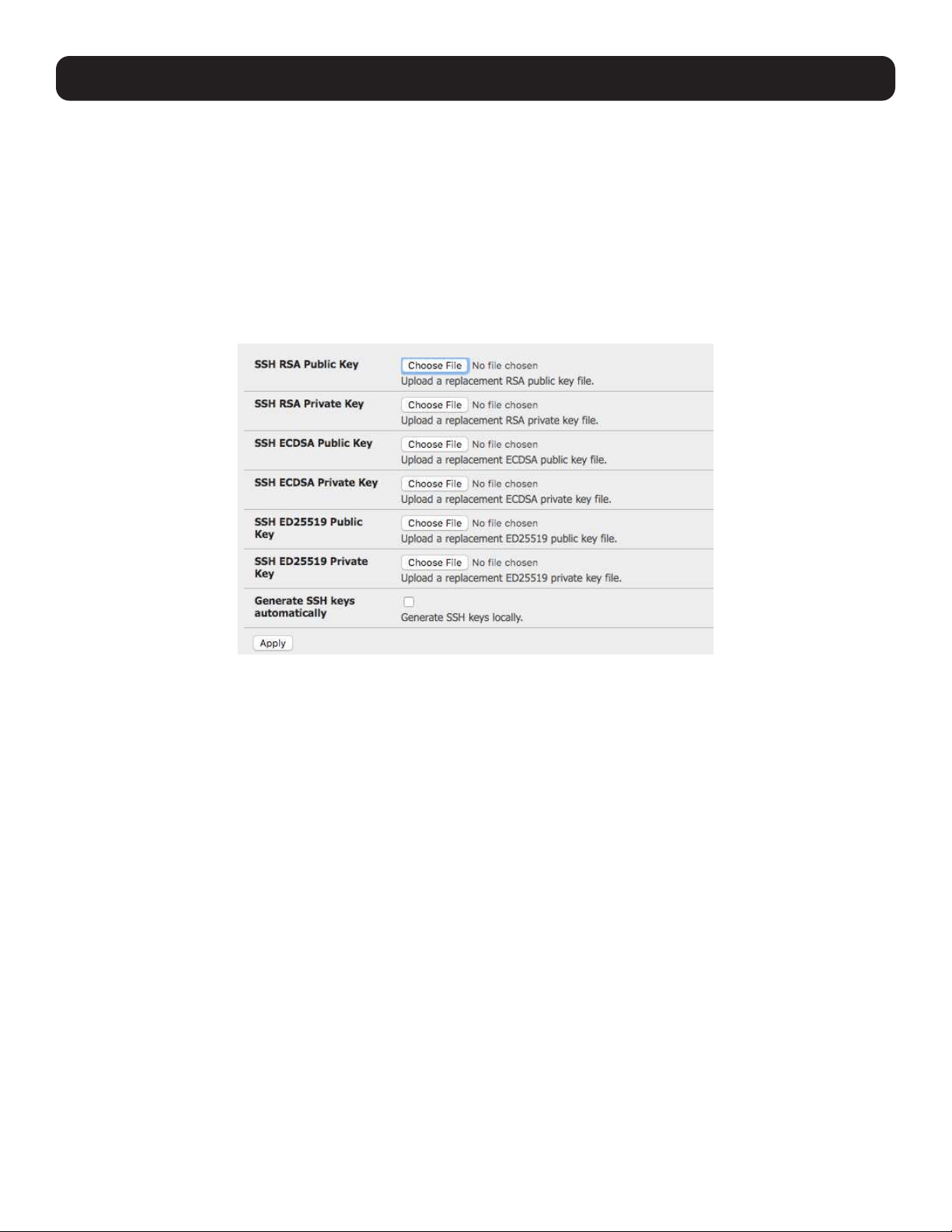
51
4.6.2 Manually Generate and Upload SSH Keys
Alternately, if you have a RSA or DSA key pair you can manually upload them to the Primary and Secondary console servers.
Note: If you do not already have RSA or DSA key pair and you do not wish to use you will need to create a key pair using ssh-keygen,
PuTTYgen or a similar tool as detailed in 15.6 Secure Shell (SSH) Public Key Authentication.
To manually upload the public and private key pair to the Primary console server:
• Select System: Administration on the Primary unit’s management console.
• Browse to the location you saved the RSA (or DSA) public key and upload it to SSH RSA (DSA) Public Key.
• Browse to the saved RSA (or DSA) private key location and upload it to SSH RSA (DSA) Private Key.
• Click Apply.
Next, you must register the public key as an authorized key on the Secondary unit. You will only need to upload one RSA or
DSA public key for each Secondary unit.
Note: The use of key pairs may be confusing because in many cases, one file (public key) fulfills two roles – public key and authorized key.
For a more information, refer to 15.6 Secure Shell (SSH) Public Key Authentication.
Select System: Administration on the Secondary unit’s management console
• Browse again to the saved RSA (or DSA) public key and upload it to the Secondary unit’s SSH Authorized Key.
• Click Apply.
The next step is to Fingerprint each new Secondary-Primary connection. This once-off step will validate your SSH session. On
first connection, the Secondary will receive a fingerprint from the Primary unit, which will be used on all future connections:
• To establish the fingerprint, first log in to the Primary server as root and establish an SSH connection to the Secondary
remote host:
# ssh remhost
Once the SSH connection has been established you will be asked to accept the key. Answer yes and the fingerprint will be
added to the list of known hosts. Refer to 15.6 Secure Shell (SSH) Public Key Authentication for more information.
• If asked to supply a password, there is a problem with uploading keys. The keys should remove any need to supply a
password.
4. Serial Port, Host, Device and User Configuration
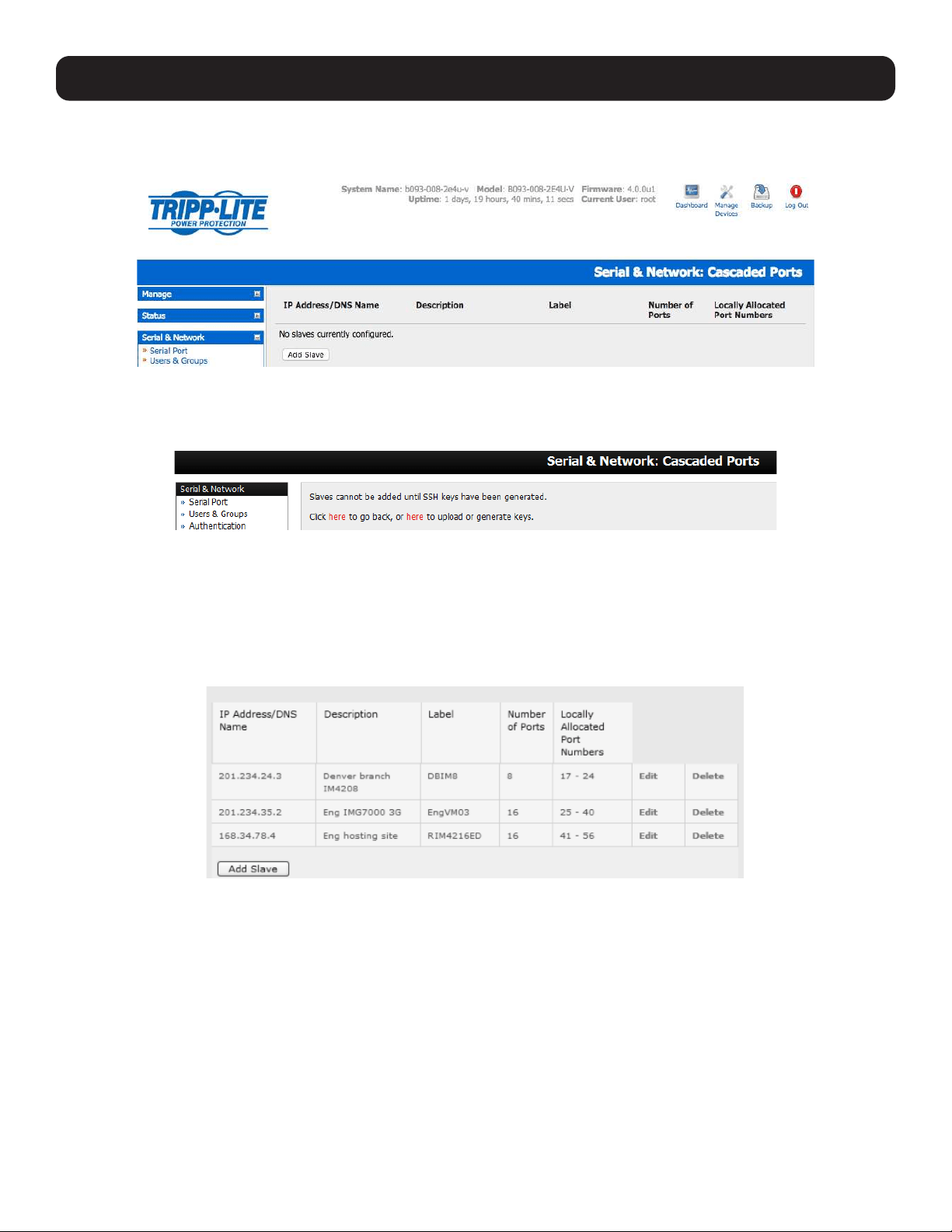
52
4. Serial Port, Host, Device and User Configuration
4.6.3 Configure the Secondary Units and their Serial Ports
To begin setting up the Secondary units and configuring Secondary serial ports from the Primary console server:
• Select Serial & Network: Cascaded Ports on the Primary unit’s management console:
• To add clustering support, select Add Slave (Secondary).
Note: You will be prevented from adding any Secondary units until you have automatically or manually generated SSH keys:
To define and configure a Secondary console server:
• Enter the remote IP Address (or DNS Name) for the Secondary console server.
• Enter a brief Description and a short Label for the Secondary unit (use a convention here that enables effective
management of large networks of clustered console servers and the connected devices).
• Enter the full number of serial ports on the Secondary unit in Number of Ports.
• Click Apply. This will establish the SSH tunnel between the Primary unit and the new Secondary unit.
The Serial & Network: Cascaded Ports menu displays all Secondary units and port numbers that have been allocated on
the Primary unit. For example, if the Primary console server has 16 ports of its own, then ports 1-16 are pre-allocated to the
Primary unit. As a result, the first Secondary unit added will be assigned port number 17.
Once you have added all the Secondary console servers, the Secondary’s serial ports and the connected devices are
configurable and accessible from the Primary unit’s management console menu, accessible through the Primary’s IP address.
• Select the appropriate Serial & Network: Serial Port and Edit to configure the serial ports on the Secondary unit.
• Select the appropriate Serial & Network: Users & Groups to add new users with access privileges to the Secondary unit’s
serial ports (or to extend existing users access privileges).
• Select the appropriate Serial & Network: Trusted Networks to specify network addresses that can access assigned
Secondary serial ports.
• Select the appropriate Alerts & Logging: Alerts to configure Secondary port Connection, State Change or Pattern Match
alerts.
• The configuration changes made on the Primary unit are propagated out to all the Secondary units when you click Apply.
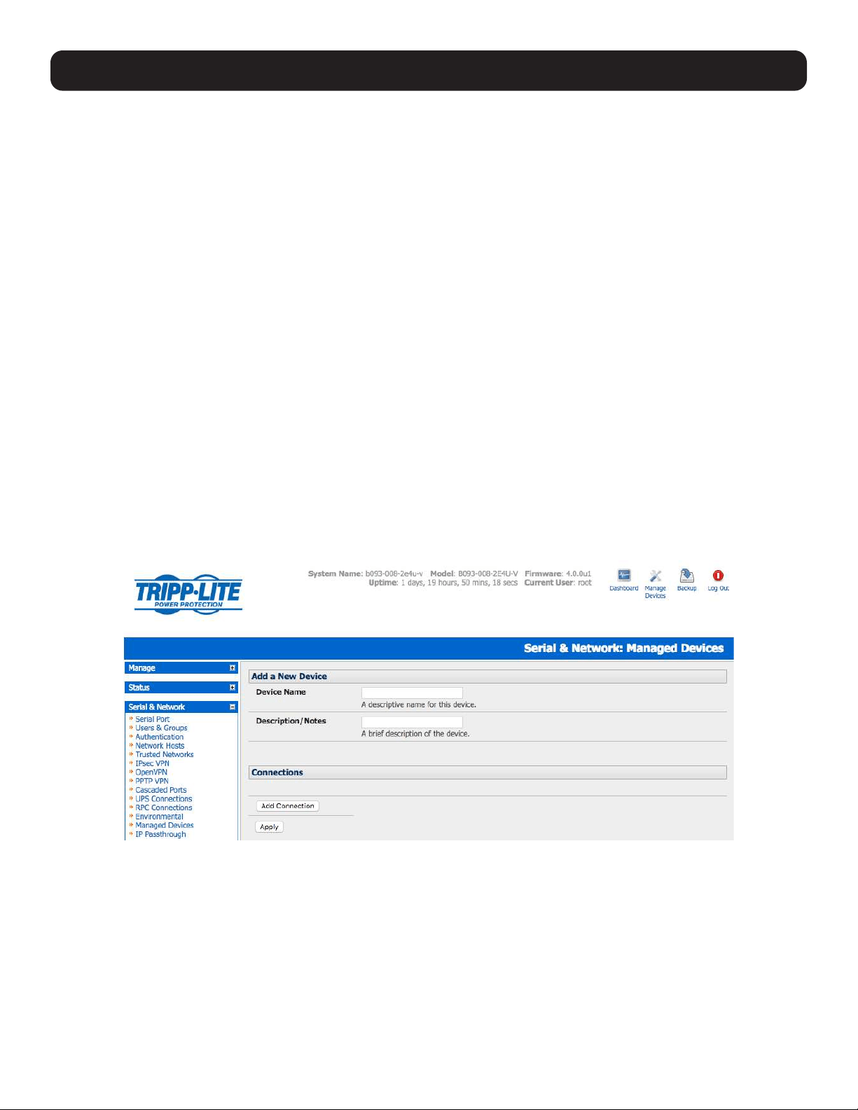
53
4.6.4 Managing the Secondary Serial Ports
The Primary console server is in control of the Secondary units’ serial ports. For example, when changing a User’s access
privileges or editing any serial port setting on the Primary unit, the updated configuration files will be sent out to each
Secondary in parallel. Each Secondary unit will then automatically make changes to their local configurations (and only make
those changes that relate to its particular serial ports).
You can still use the local secondary management console to change the settings on any Secondary serial port (e.g., alter the
baud rates). However, these changes will be overwritten the next time the Primary console server sends out a configuration file
update.
Also, while the Primary unit is in control of all Secondary serial port related functions, it is not Primary over the Secondary
network host connections or over the Secondary console server system itself.
So Secondary functions such as IP, SMTP & SNMP Settings and Date & Time, DHCP server must be managed by accessing
each Secondary unit directly. These functions are not overwritten when configuration changes are propagated from the Primary
console server. Similarly, the Secondary unit’s Network Host and IPMI settings have to be configured at each Secondary unit.
The Primary unit’s management console also provides a consolidated view of the settings for both serial ports as well as the
serial ports for the entire Secondary units. However, the Primary unit does not provide a fully consolidated view. For example, if
you want to view who has logged in to cascaded serial ports from the Primary unit, you will see that Status: Active Users only
displays those users active on the Primary unit’s ports and you may need to write custom scripts to provide this view. For more
information, refer to 10. Nagios Integration.
4.7 Managed Devices
Managed devices present a consolidated view of all connections to a device that can be accessed and monitored through the
console server. To view the connections to devices:
• Select Serial & Network: Managed Devices.
This screen displays all the managed devices with their Description/Notes and lists of all configured connections:
• Serial Port # (if serially connected) or
• USB (if USB connected)
• IP Address (if network connected)
• Power PDU/outlet details (if applicable) and any UPS connections
Devices such as servers will commonly have more than one power connection (e.g., dual power supplied) and more than one
network connection (e.g., for BMC/service processor).
All users can view (but not edit) these managed device connections by selecting Manage: Devices. Only the Administrator can
edit and add/delete managed devices and their connections.
4. Serial Port, Host, Device and User Configuration
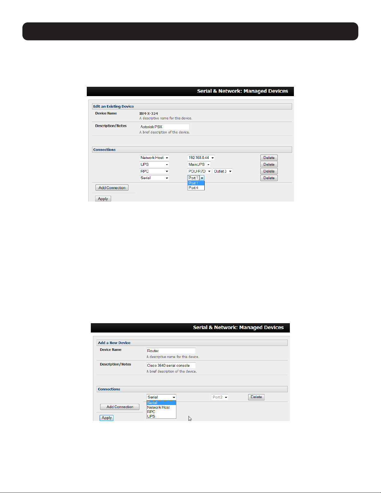
54
4. Serial Port, Host, Device and User Configuration
To edit an existing device and add a new connection:
• Select Edit on the Serial & Network: Managed Devices and click Add Connection.
• Select the connection type for the new connection (Serial, Network Host, UPS or RPC). Then select the specific connection
from the presented list of configured unallocated hosts/ports/outlets.
To add a new network-connected managed device:
• The Administrator adds a new network-connected Managed Device using Add Host on the Serial & Network: Network
Host menu. This automatically creates a corresponding new managed device (refer to 4.4 Network Hosts)
• When adding a new network-connected RPC or UPS power device, you set up a Network Host, designate it as RPC or
UPS, then go to RPC Connections (or UPS Connections) to configure the relevant connection. Again corresponding
new Managed Device (with the same Name /Description as the RPC/UPS Host) is not created until this connection step is
completed (refer to 8. Power, Environment and Digital I/O).
Note: The outlet names on this newly created PDU are by default “Outlet 1” “Outlet 2”. When connecting a particular managed device that
draws power from the outlet, the outlet will take the name of the powered managed device.
To add a new serially connected managed device:
• Configure the serial port using the Serial & Network: Serial Port menu (refer to 4.1 Configure Serial Ports).
• Select Serial & Network: Managed Devices and click Add Device.
• Enter a Device Name and Description for the managed device.
• Click Add Connection. Select Serial and the Port that connects to the managed device.
• To add a UPS/RPC power connection, network connection or another serial connection, click Add Connection.
• Click Apply.
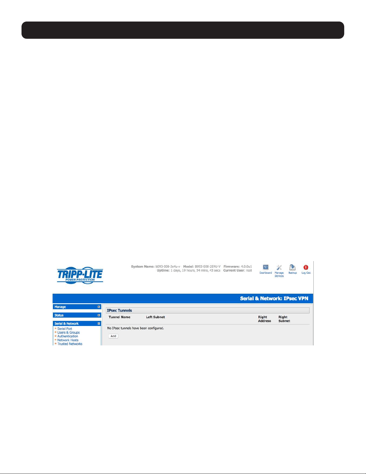
55
Note: To set up a new serially connected RPC, UPS or EMD device, first configure the serial port, designate it as a device, and then enter a
name and description for that device in the Serial & Network: RPC Connections (or UPS Connections or Environmental). When applied,
this will automatically create a corresponding new managed device with the same name/description as the RPC/UPS host (refer to 8. Power,
Environment and Digital I/O).
The outlet names on the PDU are by default “Outlet 1” “Outlet 2”. When connecting a particular managed device that draws power from the
outlet, the outlet will take the name of the powered managed device.
4.8 IPsec VPN
The console servers include Openswan, a Linux implementation of the IPsec (IP security) protocols, which can be used to
configure a Virtual Private Network (VPN). The VPN allows multiple sites or remote administrators to access the Tripp Lite
advanced console server (and managed devices) securely over the internet.
The administrator can establish encrypted authenticated VPN connections between advanced console servers distributed at
remote sites and a VPN gateway (such as Cisco router running IOS IPsec) on their central office network:
• Users and administrators at the central office can then securely access the remote console. servers and connected serial
console devices and machines on the Management LAN subnet at the remote location as though they were local.
• With serial bridging, serial data from controller at the central office machine can be securely connected to the serially
controlled devices at the remote sites (refer to 4.1 Configure Serial Ports).
The road warrior administrator can use a VPN IPsec software client such as TheGreenBow (www.thegreenbow.com/vpn_
gateway.html) or Shrew Soft (www.shrew.net/support ) to remotely access the advanced console server and every machine on
the Management LAN subnet at the remote location.
Configuration of IPsec is quite complex so Tripp Lite provides a simple GUI interface for basic set up as described below.
However, for more detailed information on configuring Openswan IPsec at the command line and interconnecting with other
IPsec VPN gateways and road warrior IPsec software, refer http://wiki.openswan.org
4.8.1 Enable the VPN Gateway
Select IPsec VPN on the Serial & Networks menu.
4. Serial Port, Host, Device and User Configuration

56
4. Serial Port, Host, Device and User Configuration
Click Add and complete the Add IPsec Tunnel screen.
Enter any descriptive name you wish to identify the IPsec Tunnel you are adding, such as WestStOutlet-VPN.
Select the Authentication Method to be used, either RSA digital signatures or a Shared secret (PSK).
• If you select RSA, you will be asked click here to generate keys. This will generate an RSA public key for the console
server (the Left Public Key). You will need to find out the key to be used on the remote gateway, and then cut and paste
it into the Right Public Key.
o If you select Shared secret, you will need to enter a pre-shared secret (PSK). The PSK must match the PSK configured at
the other end of the tunnel.

57
In Authentication Protocol, select the authentication protocol to be used. Either authenticate as part of ESP (Encapsulating
Security Payload) encryption or separately using the AH (Authentication Header) protocol.
Enter a Left ID and Right ID. The local host/gateway and remote host/gateway use this identifier for IPsec negotiation and
authentication. Each ID must include a ‘@’ and can include a fully qualified domain name preceded by ‘@’ (e.g. left@
example.com).
Enter the public IP or DNS address of this Tripp Lite VPN gateway as the Left Address. You can leave this blank to use the
interface of the default route.
In Right Address, enter the public IP or DNS address of the remote end of the tunnel (only if the remote end has a static or
dyndns address). Otherwise, leave this blank.
If the Tripp Lite VPN gateway is serving as a VPN gateway to a local subnet (e.g. the console server has a management LAN
configured), enter the private subnet details in Left Subnet. Use the CIDR notation (where the IP address number is followed
by a slash and the number of ‘one’ bits in the binary notation of the netmask). For example, 192.168.0.0/24 indicates an IP
address where the first 24 bits are used as the network address. This is the same as 255.255.255.0. If the VPN access is
only to the console server itself and to its attached serial console devices, leave Left Subnet blank.
If there is a VPN gateway at the remote end, enter the private subnet details in Right Subnet. Again, use the CIDR notation
and leave blank if there is only a remote host.
Select Initiate Tunnel if the tunnel connection is to be initiated from the Left console server end. This can only be initiated
from the VPN gateway (Left) if the remote end was configured with a static (or dyndns) IP address.
Click Apply to save changes.
Note: It is essential the configuration details set up on the advanced console server (referred to as the Left or Local host) exactly match the
setup entered when configuring the Remote (Right) host/gateway or software client.
4.9 OpenVPN
Console servers with firmware version 3.2 and later include OpenVPN. OpenVPN uses the OpenSSL library for encryption,
authentication, and certification, which means it uses SSL/TSL (Secure Socket Layer/Transport Layer Security) for key
exchange and can encrypt both data and control channels. Using OpenVPN allows for the building of cross-platform, point-to-
point VPNs using either X.509 PKI (Public Key Infrastructure) or custom configuration files.
OpenVPN allows secure tunneling of data through a single TCP/UDP port over an unsecured network, thus providing secure
access to multiple sites and secure remote administration to a console server over the Internet.
OpenVPN also allows the use of Dynamic IP addresses by both the server and client, thus providing client mobility. For
example, an OpenVPN tunnel may be established between a roaming windows client and a Tripp Lite advanced console server
within a data center.
Configuration of OpenVPN can be a complex undertaking. For ease and convenience, Tripp Lite provides a simple GUI interface
for basic set up as described below. For more detailed information on configuring OpenVPN Access server or client, refer to the
HOW TO and FAQs at http://www.openvpn.net.
4. Serial Port, Host, Device and User Configuration
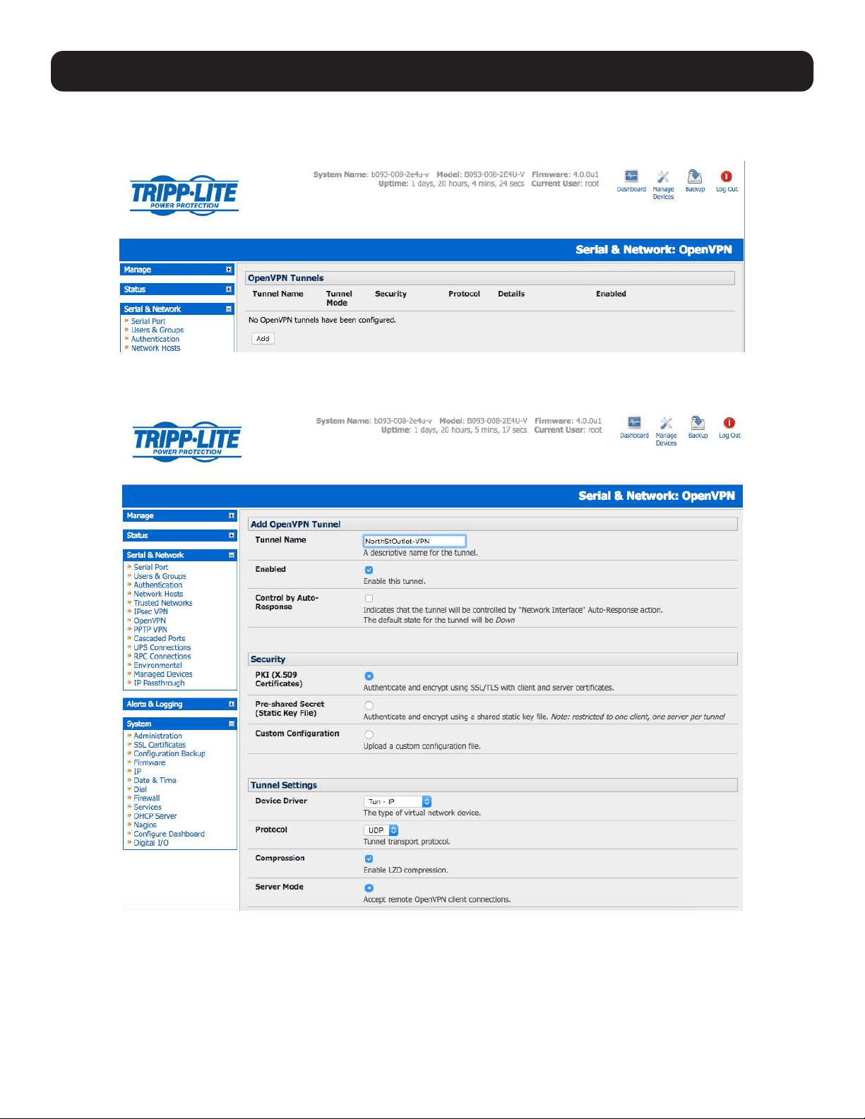
58
4. Serial Port, Host, Device and User Configuration
4.9.1 Enable the OpenVPN
Select OpenVPN on the Serial & Networks menu.
Click Add and complete the Add OpenVPN Tunnel screen.
Enter any descriptive name you wish to identify the OpenVPN Tunnel you are adding, for example NorthStOutlet-VPN.
Select the authentication method to be used. To authenticate using certificates, select PKI (X.509 Certificates) or select
Custom Configuration to upload custom configuration files. Custom configurations must be stored in /etc/config.
Note: If you select PKI (public key infrastructure), you will need to establish:
• Separate certificate (also known as a public key). This Certificate File will be a *.crt file type
• Private Key for the server and each client. This Private Key File will be a *.key file type
• Primary Certificate Authority (CA) certificate and key, which is used to sign each of the server and client certificates. This Root CA
Certificate will be a *.crt file type
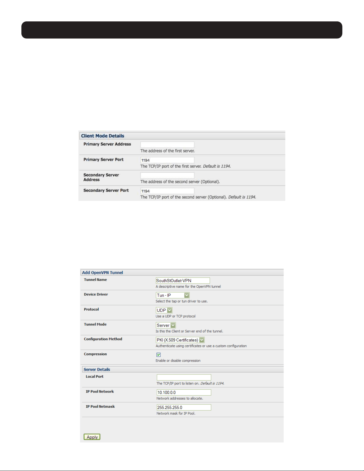
59
For a server you may also need dh1024.pem (Diffie Hellman parameters). Refer to http://openvpn.net/easyrsa.html
for a guide on basic RSA key management. For alternative authentication methods, go to http://openvpn.net/index.php/
documentation/howto.html#auth. For more information, go to http://openvpn.net/howto.html.
• Select the Device Driver to be used, either Tun-IP or Tap-Ethernet. The TUN (network tunnel) and TAP (network tap)
drivers are virtual network drivers that support IP tunneling and Ethernet tunneling, respectively. TUN and TAP are part of the
Linux kernel.
• Select either UDP or TCP as the Protocol. UDP is the default and preferred protocol for OpenVPN.
• In Tunnel Settings, assign whether this is the Client or Server end of the tunnel. When running as a server, the advanced
console server supports multiple clients connecting to the VPN server over the same port.
• Check or uncheck the Compression button to enable or disable compression.
4.9.2 Configure as Server or Client
Complete the Client Details or Server Details, depending on the Tunnel Mode selected.
• If Client has been selected, the Primary Server Address will be the address of the OpenVPN Server.
• If Server has been selected, enter the IP Pool Network address and the IP Pool Network mask for the IP Pool. The network
defined by the IP Pool Network address/mask is used to provide the addresses for connecting clients.
Click Apply to save changes.
4. Serial Port, Host, Device and User Configuration
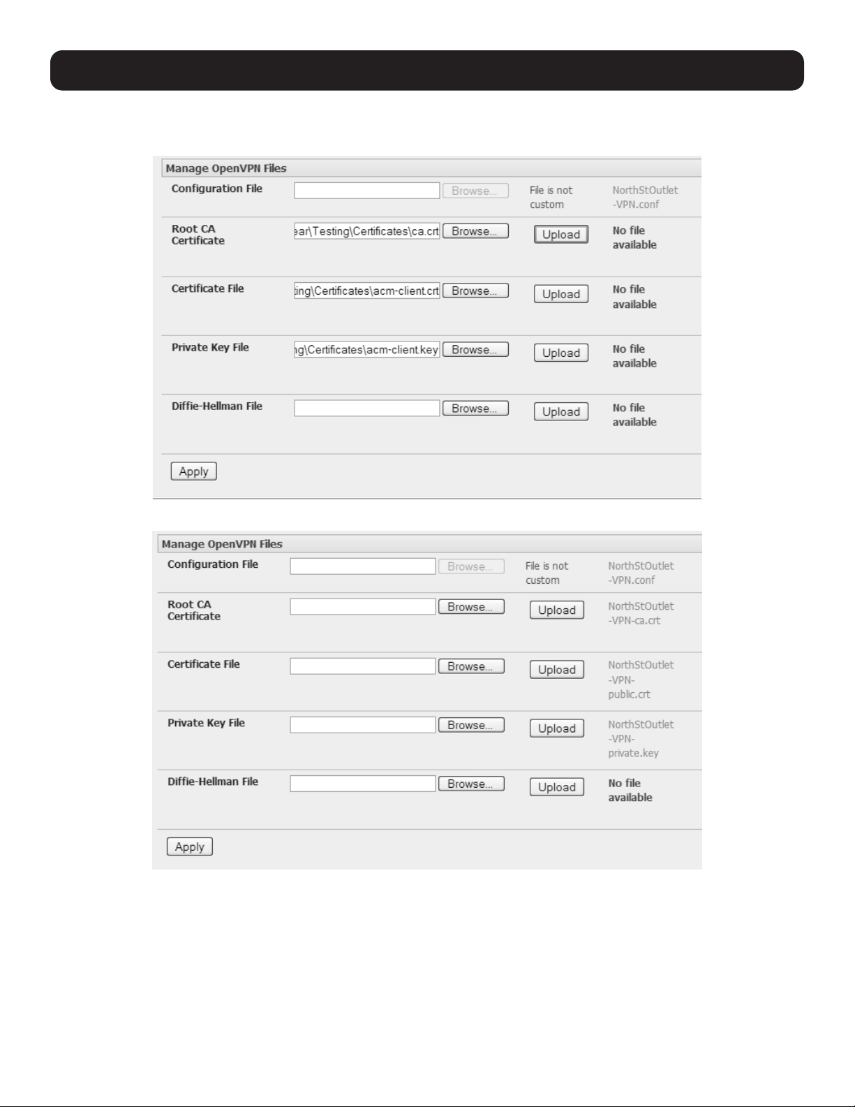
60
4. Serial Port, Host, Device and User Configuration
To enter authentication certificates and files, Edit the OpenVPN tunnel.
Select the Manage OpenVPN Files tab. Upload or browse to relevant authentication certificates and files.
Click Apply to save changes. Saved files will be displayed in red on the right-hand side of the Upload button.
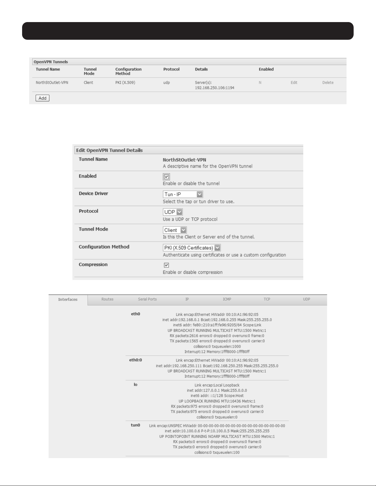
61
To enable OpenVPN, Edit the OpenVPN tunnel.
Check the Enabled button.
Click Apply to save changes.
Note: Please make sure that the console server system time is correct when working with OpenVPN. Otherwise, authentication issues may
arise.
Select Statistics on the Status menu to verify that the tunnel is operational.
4. Serial Port, Host, Device and User Configuration

62
4. Serial Port, Host, Device and User Configuration
4.9.3 Set Up Windows OpenVPN Client and Server
Windows does not come standard with any OpenVPN server or client. This section outlines the installation and configuration of
a Windows OpenVPN client or a Windows OpenVPN server and setting up a VPN connection to a console server.
Console servers with firmware version 3.5.2 and later will generate Windows client configurations automatically from the GUI
for Pre-shared Secret (Static Key File) configurations.
Alternately, OpenVPN GUI for Windows software (which includes the standard OpenVPN package, plus a Windows GUI) can be
downloaded from http://openvpn.se/download.html.
• Once installed on the Windows machine, an OpenVPN icon will have been created in the Notification Area located in the
right side of the taskbar. Right click on this icon to start (and stop) VPN connections, edit configurations and view logs.
When the OpenVPN software is running, the C:\Program Files\OpenVPN\config folder will be scanned for “.opvn” files. This
folder will be rechecked for new configuration files whenever the OpenVPN GUI icon is right clicked. Once OpenVPN is installed,
a configuration file will need to be created:
• Using a text editor, create an xxxx.ovpn file and save in C:\Program Files\OpenVPN\config.
For example, C:\Program Files\OpenVPN\config\client.ovpn.
An example of an OpenVPN Windows client configuration file is shown below:
# description: B098_client
client
proto udp
verb 3
dev tun
remote 192.168.250.152
port 1194
ca c:\\openvpnkeys\\ca.crt
cert c:\\openvpnkeys\\client.crt
key c:\\openvpnkeys\\client.key
nobind
persist-key
persist-tun
comp-lzo

63
4. Serial Port, Host, Device and User Configuration
An example of an OpenVPN Windows Server configuration file is shown below:
server 10.100.10.0 255.255.255.0
port 1194
keepalive 10 120
proto udp
mssfix 1400
persist-key
persist-tun
dev tun
ca c:\\openvpnkeys\\ca.crt
cert c:\\openvpnkeys\\server.crt
key c:\\openvpnkeys\\server.key
dh c:\\openvpnkeys\\dh.pem
comp-lzo
verb 1
syslog B098_OpenVPN_Server
The Windows client/server configuration file options are:
Options Description
#description: This is a comment describing the configuration.
Comment lines start with “#” and are ignored by OpenVPN.
Client server Specify whether this will be a client or server configuration file.
In the server configuration file, define the IP address pool and netmask. For example,
server 10.100.10.0 255.255.255.0.
proto udp
proto tcp
Set the protocol to UDP or TCP. The client and server must use the same settings.
mssfix <max. size> Mssfix sets the maximum size of the packet. This is only useful for UDP if problems
occur.
verb <level> Set log file verbosity level. Log verbosity level can be set from 0 (minimum) to 15
(maximum). For example,
0 = silent except for fatal errors
3 = medium output, good for general usage
5 = helps with debugging connection problems
9 = extremely verbose, excellent for troubleshooting
dev tun
dev tap
Select dev tun to create a routed IP tunnel or dev tap to create an Ethernet tunnel.
The client and server must use the same settings.
remote <host> The hostname/IP of OpenVPN server when operating as a client. Enter either the DNS
hostname or the static IP address of the server.
Port The UDP/TCP port of the server.
Keepalive Keepalive uses ping to keep the OpenVPN session alive. “Keepalive 10 120” pings
every 10 seconds and assumes the remote peer is down if no ping has been received
over a 120 second time period.
http-proxy <proxy server>
<proxy port #>
If a proxy is required to access the server, enter the proxy server DNS name or IP and
port number.
ca <file name> Enter the CA certificate file name and location.
The same CA certificate file can be used by the server and all clients.
Note: Ensure each “\” in the directory path is replaced with “\\”. For example, c:\openvpnkeys\
ca.crt will become c:\\openvpnkeys\\ca.crt.
cert <file name> Enter the client’s or server’s certificate file name and location.
Each client should have its own certificate and key files.
Note: Ensure each “\” in the directory path is replaced with “\\”.
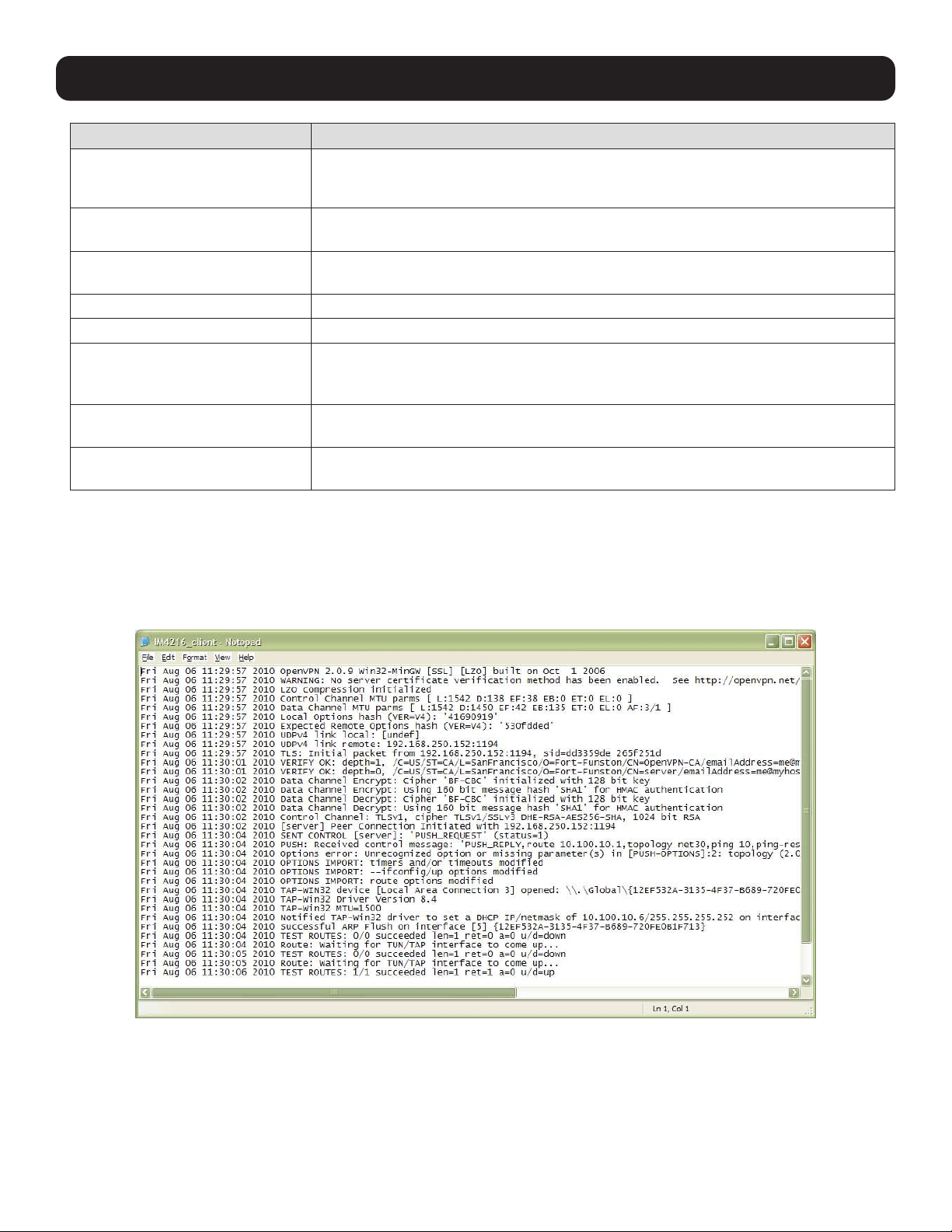
64
4. Serial Port, Host, Device and User Configuration
Options Description
key <file name> Enter the file name and location of the client’s or server’s key.
Each client should have its own certificate and key files.
Note: Ensure each “\” in the directory path is replaced with “\\”.
dh <file name> This is used by the server only.
Enter the path to the key with the Diffie-Hellman parameters.
Nobind “Nobind” is used when clients do not need to bind to a local address or specific local
port number. This is the case in most client configurations.
persist-key This option prevents the reloading of keys across restarts.
persist-tun This option prevents the close and reopen of TUN/TAP devices across restarts.
cipher BF-CBC Blowfish (default)
cipher AES-128-CBC AES
cipher DES-EDE3-CBC Triple-DES
Select a cryptographic cipher. The client and server must use the same settings.
comp-lzo Enable compression on the OpenVPN link. This must be enabled on both the client
and the server.
syslog By default, logs are located in syslog or, if running as a service on Window, in \
Program Files\OpenVPN\log directory.
To initiate the OpenVPN tunnel following the creation of the client/server configuration files:
• Right click on the OpenVPN icon in the Notification Area.
• Select the newly created client or server configuration. For example, B098_client.
• Right click on the OpenVPN icon in the lower-right corner, select the desired client and click Connect.
• The log file will display as the connection is established.

65
• Once established, the OpenVPN icon will display a message notifying the successful connection and assigned IP. This
information, as well as the time the connection was established, is available anytime by scrolling over the OpenVPN icon.
Note: An alternate OpenVPN Windows client can be downloaded from http://www.openvpn.net/index.php/openvpn-client/downloads.html.
Refer to http://www.openvpn.net/index.php/openvpn-client/howto-openvpn-client.html for help.
4.10 PPTP VPN
Console servers with firmware version 3.5.2 and later include a PPTP (Point-to-Point Tunneling Protocol) server. PPTP is
typically used for communications over a physical or virtual serial link. The PPP endpoints define a virtual IP address to
themselves. Routes to networks can then be defined with these IP addresses as the gateway, which results in traffic being
sent across the tunnel. PPTP establishes a tunnel between the physical PPP endpoints and securely transports data across the
tunnel.
The strength of PPTP is its ease of configuration and integration into existing Microsoft infrastructure. It is generally used for
connecting single remote Windows clients. If you take your portable computer on a business trip, you can dial a local number
to connect to your Internet access service provider (ISP) and then create a second connection (tunnel) into your office network
across the Internet and have the same access to your corporate network as if you were connected directly from your office.
Similarly, telecommuters also set up a VPN tunnel over their cable modem or DSL links to their local ISP.
To set up a PPTP connection from a remote Windows client to your Tripp Lite console server and local network:
1. Enable and configure the PPTP VPN server on your Tripp Lite console server.
2. Set up VPN user accounts on the Tripp Lite console server and enable the appropriate authentication.
3. Configure the VPN clients at the remote sites. The client does not require special software as the PPTP Server supports the
standard PPTP client software included with Windows NT and later.
4. Connect to the remote VPN.
4. Serial Port, Host, Device and User Configuration
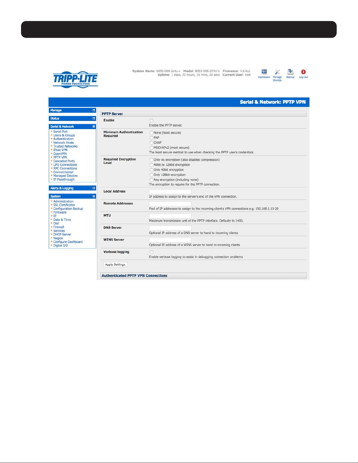
66
4. Serial Port, Host, Device and User Configuration
4.10.1 Enable the PPTP VPN Server
Select PPTP VPN on the Serial & Networks menu.
Select the Enable check box to enable the PPTP Server.
Select the Minimum Authentication Required. Access is denied to remote users attempting to connect using an
authentication scheme weaker than the selected scheme. The schemes are described below, from strongest to weakest.
• Encrypted Authentication (MS-CHAP v2): This is the strongest type of authentication to use and is the recommended
option.
• Weakly Encrypted Authentication (CHAP): This is the weakest type of encrypted password authentication to use. It is not
recommended that clients connect using this as it provides very little password protection. Also, note that clients connecting
using CHAP are unable to encrypt traffic.
• Unencrypted Authentication (PAP): This is plain text password authentication. When using this type of authentication, the
client password is transmitted unencrypted.
• None.
Select the Required Encryption Level. Access is denied to remote users attempting to connect not using this encryption
level. Strong 40-bit or 128-bit encryption is recommended.
In Local Address, enter the IP address to assign to the server’s end of the VPN connection.
In Remote Addresses, enter the pool of IP addresses to assign to the incoming client’s VPN connections (e.g.
192.168.1.10-20). This must be a free IP address (or a range of free IP addresses), from the network (typically the LAN) that
remote users are assigned while connected to the Tripp Lite console server.
Enter the desired value of the Maximum Transmission Unit (MTU) for the PPTP interfaces into the MTU field (defaults to 1400).
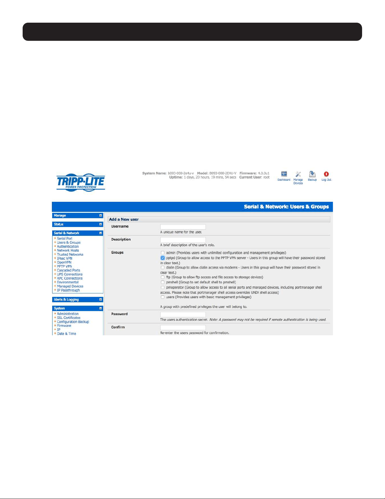
67
In the DNS Server field, enter the IP address of the DNS server that assigns IP addresses to connecting PPTP clients.
In the WINS Server field, enter the IP address of the WINS server that assigns IP addresses to connecting PPTP client.
Enable Verbose Logging to assist in debugging connection problems.
Click Apply Settings.
4.10.2 Add a PPTP User
Select Users & Groups on the Serial & Networks menu, and complete the fields as covered in section 4.2 Add and Edit
Users.
Ensure the pptpd Group has been checked to allow access to the PPTP VPN server.
Note: Users in this group will have their password stored in plain text.
Keep a note of the username and password for when you need to connect to the VPN connection.
Click Apply.
4. Serial Port, Host, Device and User Configuration
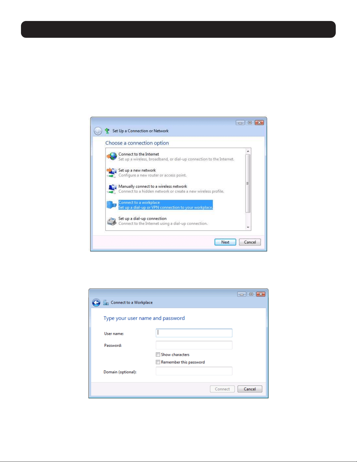
68
4. Serial Port, Host, Device and User Configuration
4.10.3 Set Up a Remote PPTP Client
Ensure the remote VPN client PC has Internet connectivity. To create a VPN connection across the Internet, you must set up
two networking connections. One connection is for the ISP and the other connection is for the VPN tunnel to the Tripp Lite
console server.
Note: This procedure sets up a PPTP client in the Windows 7 Professional operating system. The steps may vary slightly depending on your
network access or if you are using an alternate version of Windows. More detailed instructions are available from the Microsoft web site.
Log in to your Windows client with administrator privileges.
From the Network & Sharing Center on the Control Panel, select Network Connections and create a new connection.
Select Use My Internet Connection (VPN) and enter the IP Address of the Tripp Lite console server.
Note: To connect remote VPN clients to the local network, you need to know the user name and password for the PPTP account you added,
as well as the Internet IP address of the Tripp Lite console server. If your ISP has not allocated you a static IP address, consider using a
dynamic DNS service. Otherwise, you must modify the PPTP client configuration each time your Internet IP address changes.

69
4. Serial Port, Host, Device and User Configuration
4.11 IP Passthrough
IP passthrough is used to make a modem connection (e.g., Tripp Lite’s internal cellular modem) appear as a regular Ethernet
connection to a third-party downstream router. This allows the downstream router to use Tripp Lite’s modem connection as a
primary or backup WAN interface.
The console server provides the modem IP address and DNS details to the downstream device over DHCP and transparently
passes network traffic to and from the modem and router.
While IP passthrough essentially turns a console server into a modem-to-Ethernet half-bridge, some specific layer 4 services
(HTTP/HTTPS/SSH) may still be terminated at the console server (Service Intercepts). Also, services running on the console
server can initiate outbound cellular connections independent of the downstream router.
This allows the console server to continue to be used for out-of-band management and alerts while in IP passthrough mode.
4.11.1 Downstream Router Setup
To use failover connectivity on the downstream router (Failover to Cellular or F2C), it must have two or more WAN interfaces.
Note: Failover in IP passthrough context is performed entirely by the downstream router. The built-in, out-of-band failover logic on the
console server itself is not available while in IP passthrough mode.
Connect an Ethernet WAN interface on the downstream router to the network interface or management LAN port with an
Ethernet cable.
Configure this interface on the downstream router to receive its network settings via DHCP. If failover is required, configure the
downstream router for failover between its primary interface and the Ethernet port connected to the console server.
4.11.2 IP Passthrough Pre-Configuration
To enable IP passthrough:
• Configure the network interface and (where applicable) management LAN interfaces with static network settings
o Click Serial & Network: IP.
o For network interface and (where applicable) management LAN, select Static for the Configuration Method and enter
the network settings (see section 3.3 Network Connection for more information).
o For the interface connected to the downstream router, you may choose any dedicated private network. The chosen
network will only exist between the console server and downstream router and will not normally be accessible.
o For the other interface, configure it as you would per normal on the local network.
o For both interfaces, leave Gateway blank.
• Configure the modem in Always On Out-of-band mode
o For a cellular connection, click System: Dial: Internal Cellular Modem.
o Select Enable Dial-Out and enter carrier details such as APN (see section 5.6 Cellular Modem Connection for more
information).
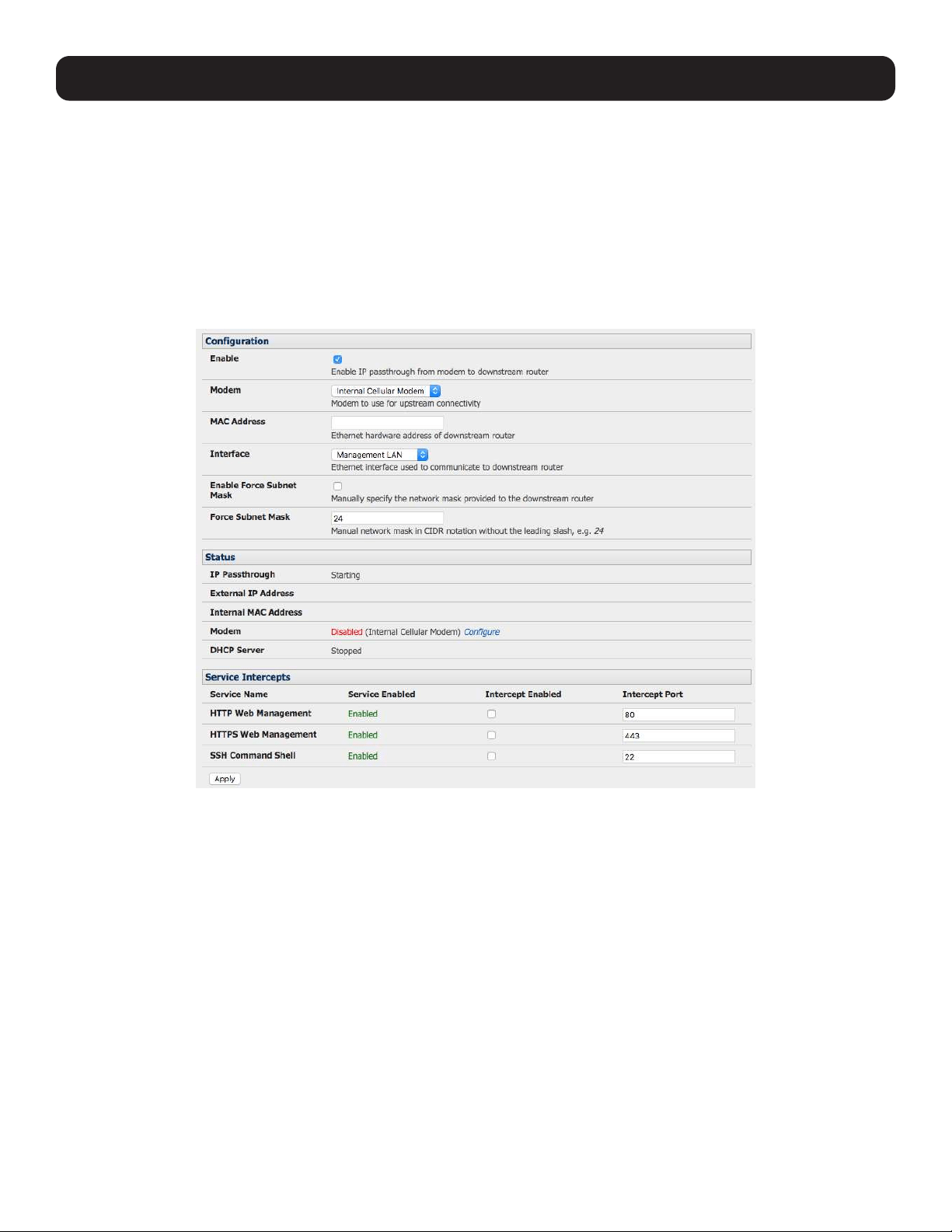
70
4. Serial Port, Host, Device and User Configuration
4.11.3 IP Passthrough Configuration
To configure IP passthrough:
• Click Serial & Network: IP Passthrough and check Enable.
• Select the Modem to use for upstream connectivity.
• Optionally, enter the MAC Address of downstream router’s connected interface.
Note: If the MAC address is not specified, the console server will pass through to the first downstream device requesting a DHCP address.
• Select the Ethernet Interface to use for connectivity to the downstream router.
• Click Apply.
4.11.4 Service Intercepts
These allow the console server to continue to provide services for out-of-band management when in IP passthrough mode.
Connections to the modem address on the specified intercept port(s) will be handled by the console server, rather than being
passed through to the downstream router.
• For the required service of HTTP, HTTPS or SSH, check Enable.
• Optionally modify the Intercept Port to an alternate port (e.g. 8443 for HTTPS). This is useful if you want to continue to
allow the downstream router to remain accessible via its regular port.
4.11.5 IP Passthrough Status
Refresh the page to view the Status section. It displays the modem’s External IP Address being passed through, the
Internal MAC Address of the downstream router (only populated when the downstream router accepts the DHCP lease), and
the overall running status of the IP passthrough service.
Additionally, you may be alerted to the failover status of the downstream router by configuring a Routed Data Usage Check
under Alerts & Logging: Auto-Response.

71
4. Serial Port, Host, Device and User Configuration
4.11.6 Caveats
Some downstream routers may be incompatible with the gateway route. This may happen when IP passthrough is bridging a
3G cellular network where the gateway address is a point-to-point destination address and no subnet information is available.
The console server sends a DHCP netmask of 255.255.255.255. Devices will normally interpret this as a “single host route”
on the interface, but as this is an unusual setting for Ethernet, some older downstream devices may encounter issues.
Intercepts for local services will not work if the console server is using a default route other than the modem. As per normal
operation, they will also not work unless the service is enabled and access to the service is enabled (see System: Services:
Service Access: Dial-Out/Cellular).
Outbound connections originating from the console server to remote services are supported (e.g. sending SMTP email alerts,
SNMP traps, getting NTP time, IPSec tunnels). There is a minor risk of connection failure should both the console server and
the downstream device try to access the same UDP or TCP port on the same remote host and at the same time where they
have randomly chosen the same originating local port number.

72
5. Firewall, Failover and OOB Access
To ensure high availability, the console server has a number of out-of-band access capabilities and transparent failover
features. If there is difficulty in accessing the console server through the main network path, all console server models provide
out-of-band (OOB) access and the Administrator can still access it (and its Managed Devices) from a remote location.
• All console server models support serially attaching an external dial-up modem and configuring dial-in OOB access. Some
models with USB ports support attaching an external USB modem. Some models also come standard with an internal
modem. These modems can also be configured for dial-in OOB access.
• All console server models with an internal or external attached modem (and firmware version 3.4 or later) can be configured
for out-dial to be permanently connected.
• The advanced console server models can also be configured for transparent out-dial failover. In the event of a disruption in
the principal management network, an external dial-up ppp connection is automatically established.
• These advanced console server models can also be accessed out-of-band using an alternate broadband link and offer
transparent broadband failover.
• Models with an internal cellular modem can be configured for OOB cellular access, cellular transparent failover, or as a
cellular router.
5.1 Dialup Modem Connection
To enable dial-in or dial-out, first ensure there is a modem attached to the console server.
• All models support external USB modems. The USB modem will be auto-detected and an External USB Modem Port tab
will appear under System -> Dial (in addition to the Serial DB9 Port tab). All console server models supports an external
modem (any brand) attached via a serial cable to the console/modem port for OOB dial-in access.
• The serial ports on the B093 are by default configured as RJ serial console server ports. However, Port 1 can be configured
to be the local console/modem port.
5.2 OOB Dial-In Access
Once a modem has been attached to the console server, you can configure the console server for dial-in PPP access. The
console server will then await an incoming connection from a dial-in at remote site. Next, the remote client dial-in software
needs to be configured to establish the connection between the Administrator’s client modem to the dial-in modem on the
console server.
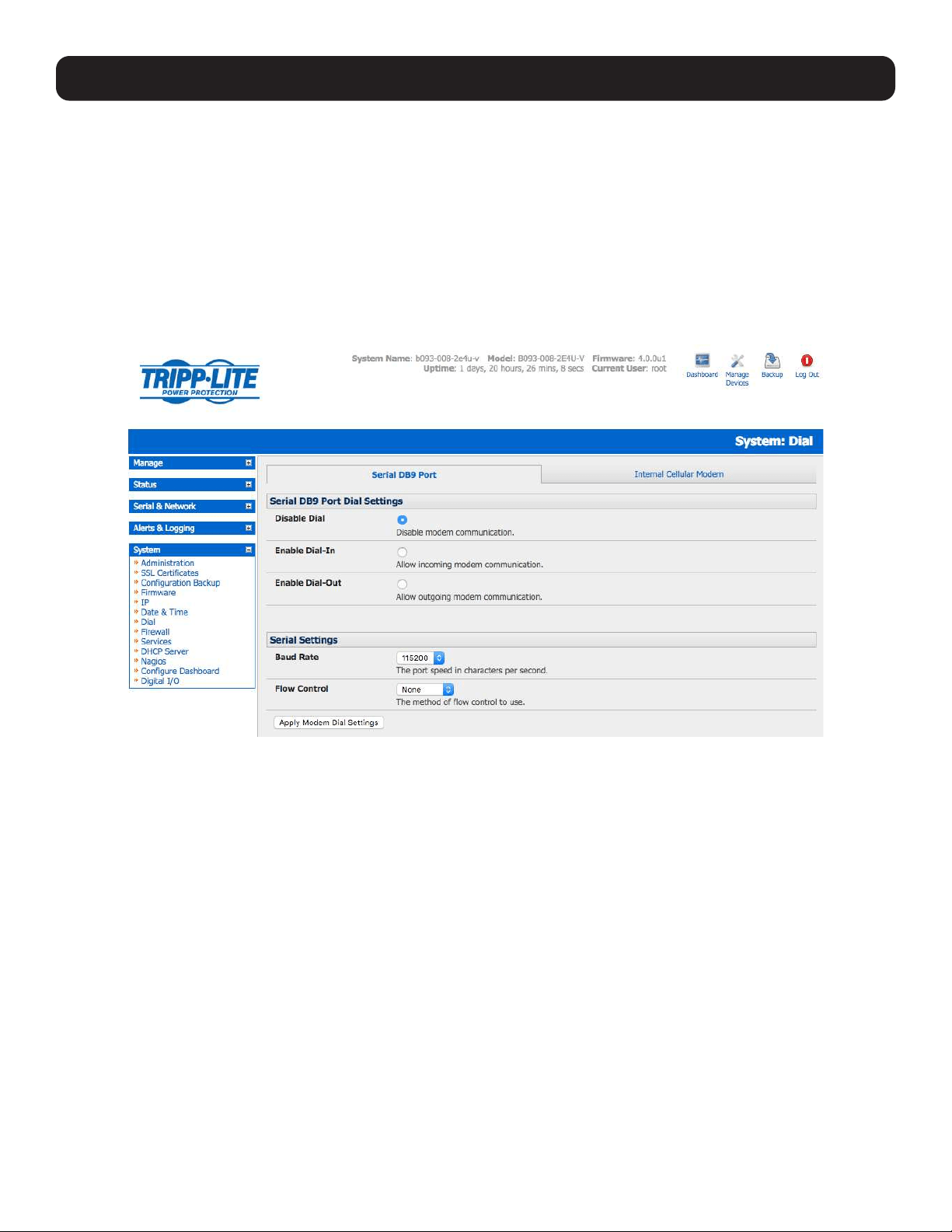
73
5.2.1 Configure Dial-In PPP
Enable PPP access on the internal or externally attached modem:
• Select the System: Dial menu option and the port to be configured (Serial DB9 Port, Internal Modem Port or External USB
Port).
• Select the Baud Rate and Flow Control that will communicate with the modem.
Note: By default, the modem port on all Tripp Lite console servers is set with software flow control. The baud rate is set at:
- 115200 for external modems connected to the local console port on B098 console servers.
- 9600 for the internal modem or external USB modem and for external modems connected to the console serial ports, which have been
reassigned for dial-in access (on B093).
When enabling OOB dial-in, it is recommended the Serial Setting be changed to 38400 baud with Hardware Flow Control.
Note: You can further configure the console/modem port (e.g. to include modem init strings) by editing /etc/mgetty.config files as described
in 14. Configuration from the Command Line.
• Check the Enable Dial-In Access box.
• In the Remote Address field, enter the IP address to be assigned to the dial-in client. You can select any address for
the Remote IP Address. However, it must be in the same network range as the Local IP Address (e.g,. 200.100.1.12 and
200.100.1.67).
• In the Local Address field, enter the IP address for the Dial-In PPP Server. This IP address will be used by the remote
client to access the console server once the modem connection is established. You can select any address for the Local IP
Address, but it must both be in the same network range as the Remote IP Address.
• The Default Route option enables the dialed PPP connection to become the default route for the console server.
• The Custom Modem Initialization option allows a custom AT string modem initialization string to be entered (e.g.
AT&C1&D3&K3).
5. Firewall, Failover and OOB Access
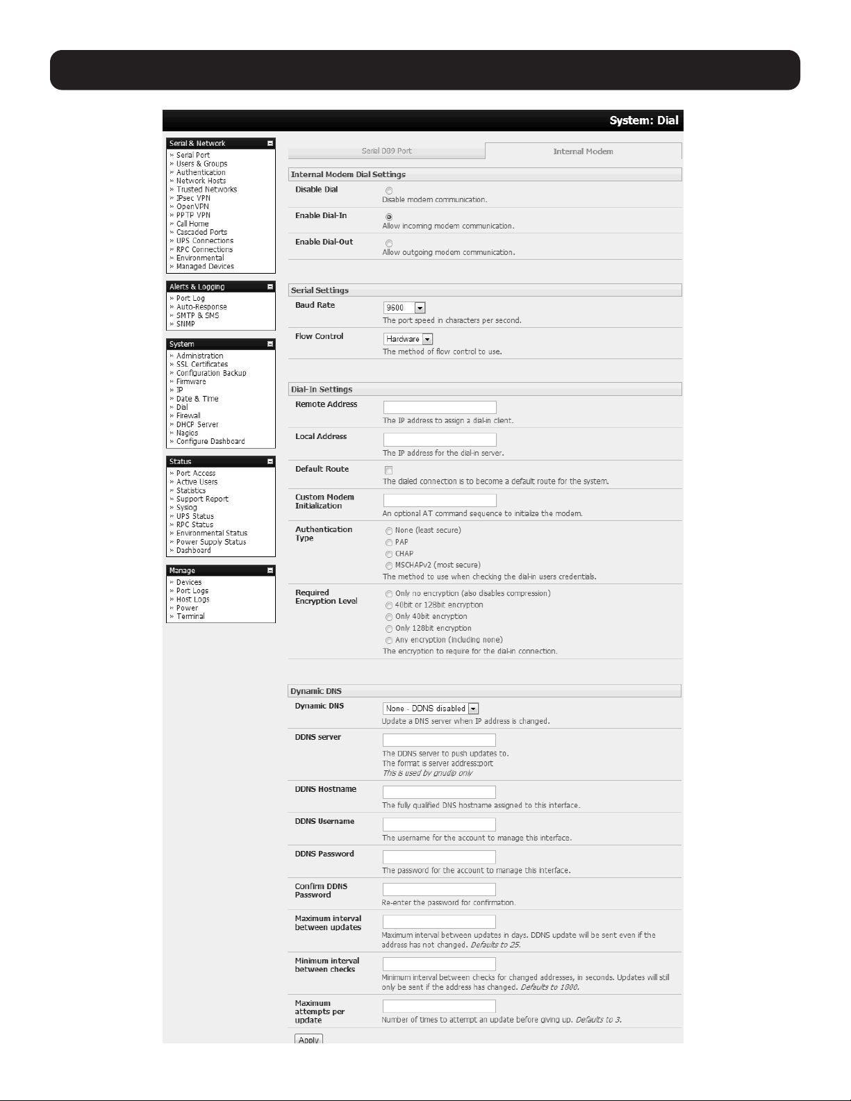
74
5. Firewall, Failover and OOB Access

75
• Select the Authentication Type required. Access is denied to remote users attempting to connect using an authentication
scheme weaker than the selected scheme. The schemes are described below, from strongest to weakest.
o Encrypted Authentication (MS-CHAP v2): This is the strongest type of authentication to use and is the recommended
option.
o Weakly Encrypted Authentication (CHAP): This is the weakest type of encrypted password authentication to use. It
is not recommended that clients connect using this, as it provides very little password protection. Also, note that clients
connecting using CHAP are unable to encrypt traffic.
o Unencrypted Authentication (PAP): This is plain text password authentication. When using this type of authentication,
the client password is transmitted unencrypted.
o None.
• Select the Required Encryption Level. Access is denied to remote users attempting to connect not using this encryption
level. Strong 40-bit or 128-bit encryption is recommended.
Notes:
Firmware version 3.5.2 and beyond support multiple dial-in users with dial-in group membership. The Username and Password to be used
for the dial-in PPP link, and any dial-back phone numbers are configured when the User is set up. Earlier firmware is only supported for one
PPP dial-in account.
Section 13. Management contains examples of Linux commands that can be used to control the modem port operation at the command
line level.
5.2.2 Using SDT Connector Client
Administrators can use their SDT connector client to set up secure OOB dial-in access to remote console servers. The
SDT connector Java client software provides point-and-click secure remote access. OOB access uses an alternate path for
connecting to the console server to that used for regular data traffic.
Starting an OOB connection in SDT connector may be achieved by initiating a dial-up connection, or adding an alternate route
to the console server. SDT connector allows for maximum flexibility is this regard by allowing you to provide your own scripts or
commands for starting and stopping the OOB connection. Refer 6.5 Using SDT Connector for Out-of-Band Connection to
the Gateway for more information.
5.2.3 Set Up Windows XP or Later Client
Open Network Connections in Control Panel and click the New Connection Wizard.
Select Connect to the Internet and click Next.
On the Getting Ready screen, select Set up my connection manually and click Next.
On the Internet Connection screen, select Connect using a dial-up modem and click Next.
Enter a Connection Name (any name you choose) and the dial-up Phone number that will connect to the console server
modem.
Enter the PPP Username and Password to set up for the console server.
5. Firewall, Failover and OOB Access

76
5. Firewall, Failover and OOB Access
5.2.4 Set Up Earlier Windows Clients
For Windows 2000, the PPP client set up procedure is the same as above, except you go to the Dial-Up Networking Folder
by clicking the Start button and selecting Settings. Then click Network and Dial-up Connections and click Make New
Connection.
Similarly, for Windows 98, double-click My Computer on the Desktop, then open Dial-Up Networking, double-click Make
New Connection and proceed as above.
5.2.5 Set Up Linux Clients
The online tutorial http://www.yolinux.com/TUTORIALS/LinuxTutorialPPP.html presents a selection of methods for establishing a
dial-up PPP connection:
• Command line PPP and manual configuration (which works with any Linux distribution).
• Using the Linuxconf configuration tool (for Red Hat compatible distributions). This configures the scripts ifup/ifdown to start
and stop a PPP connection.
• Using the Gnome control panel configuration tool.
• WVDIAL and the Redhat “Dialup configuration tool”.
• GUI dial program X-isp. Download/Installation/Configuration.
Note: For all PPP clients:
• Set the PPP link up with TCP/IP as the only protocol enabled.
• Specify the Server will assign IP address and do DNS.
• Do not set up the console server PPP link as the default for Internet connection.
5.3 Dial-Out Access
The internal or external attached modem on the console server can be set up in either:
• Failover mode, where a dial-out connection is only established in event of a ping failure
or
• With the dial-out connection always on.
In both of the above cases, during a disruption in the dial-out connection, the console server will work to re-establish the
connection.
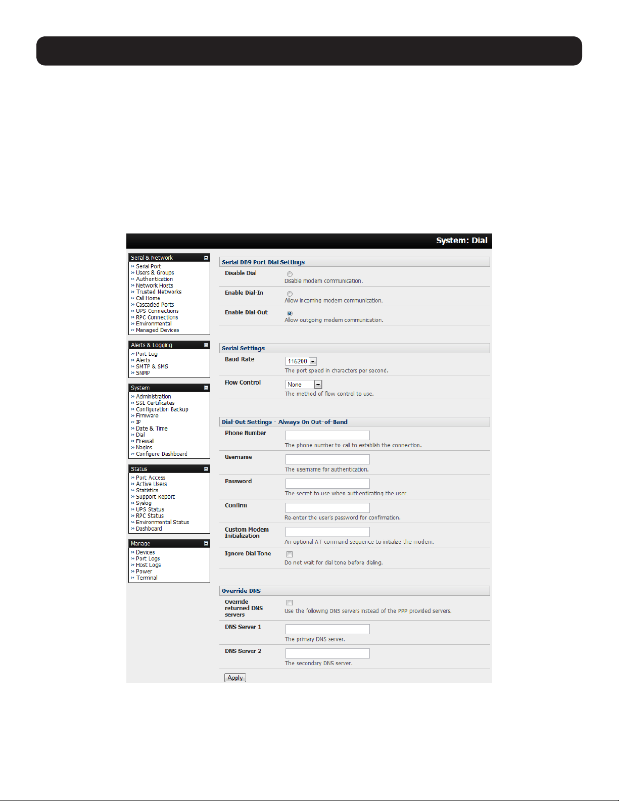
77
5.3.1 Always-On Dial-Out
With firmware version 3.4 (and later), the console server modem can be configured for out-dial to be always on, with a
permanent external dial-up ppp connection.
• Select the System: Dial menu option and check Enable Dial-Out to allow outgoing modem communications.
• Select the Baud Rate and Flow Control that will communicate with the modem.
• In the Dial-Out Settings - Always On Out-of-Band field, enter the access details for the remote PPP server to be called.
Override DNS is available for PPP Devices, such as modems. Override DNS allows the use of alternate DNS servers from
those provided by your ISP. For example, an alternative DNS may be required for OpenDNS used for content filtering.
•To enable Override DNS, check the Override Returned DNS Servers box. Enter the IP of the DNS servers into the spaces
provided.
5. Firewall, Failover and OOB Access
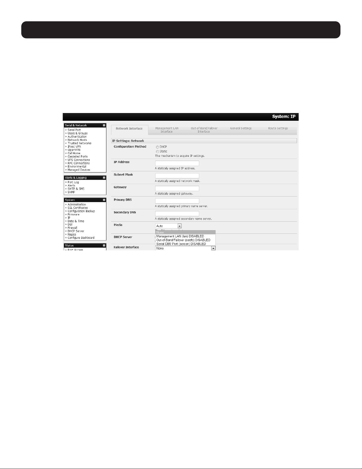
78
5.3.2 Failover Dial-Out
The console servers can be configured so a dial-out PPP connection is automatically set up in the event of a disruption in the
principal management network.
Note: Only SSH access is enabled on the failover connection. In firmware versions later than 3.0.2, HTTPS access is also enabled so the
administrator can use SSH (or HTTPS) to connect to the console server and fix the problem.
When configuring the principal network connection in System: IP, specify the failover interface that will be used when a fault
has been detected with Network / Network1 (eth0). This can be either internal modem or the dial serial DB9 (if you are using
an external modem on the console port) or USB modem (if you are using a plug-in USB modem on a B093).
• Specify the Probe Addresses of two sites (the Primary and Secondary) that the IM console server is to ping to determine if
Network / Network1 is still operational.
• Select the System: Dial menu option and the port to be configured (Serial DB9 Port, PC Card or Internal Modem Port).
• Select the Baud Rate and Flow Control that will communicate with the modem.
Note: You can further configure the console/modem port to include modem init strings by editing /etc/mgetty.config files as described in the
13. Management.
• Check the Enable Dial-Out Access box and enter the access details for the remote PPP server.
5. Firewall, Failover and OOB Access
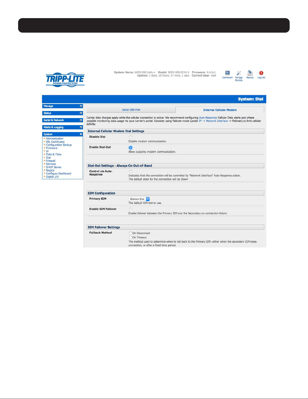
79
5. Firewall, Failover and OOB Access
Override DNS is available for PPP devices, such as modems. Override DNS allows the use of alternate DNS servers from
those provided by your ISP. For example, an alternative DNS may be required for OpenDNS used for content filtering.
• To enable Override DNS, check the Override returned DNS Servers box. Enter the IP of the DNS servers into the spaces
provided.
Note: By default, the advanced console server supports automatic failure-recovery that reverts it back to its original state prior to failover
(firmware version 3.1.0 and later). The advanced console server continually pings probe addresses while in original and failover states. The
original state will automatically be set as a priority and reestablished following three successful pings of the probe addresses during failover.
The failover state will be removed once the original state has been re-established.
5.4 OOB Broadband Ethernet Access
The console servers have a second Ethernet port that can be configured for alternate and OOB (out-of-band) broadband
access. With two active broadband access paths to these advanced console servers, you can still access it through the
alternate broadband path in the event you are unable to access through the primary management network (LAN1, Network or
Network1).
• On the System: IP menu, select Management LAN Interface and configure the IP Address, Subnet Mask, Gateway
and DNS with the access settings that relate to the alternate link.
• Ensure when configuring the principal Network Interface connection, the Failover Interface is set to None.
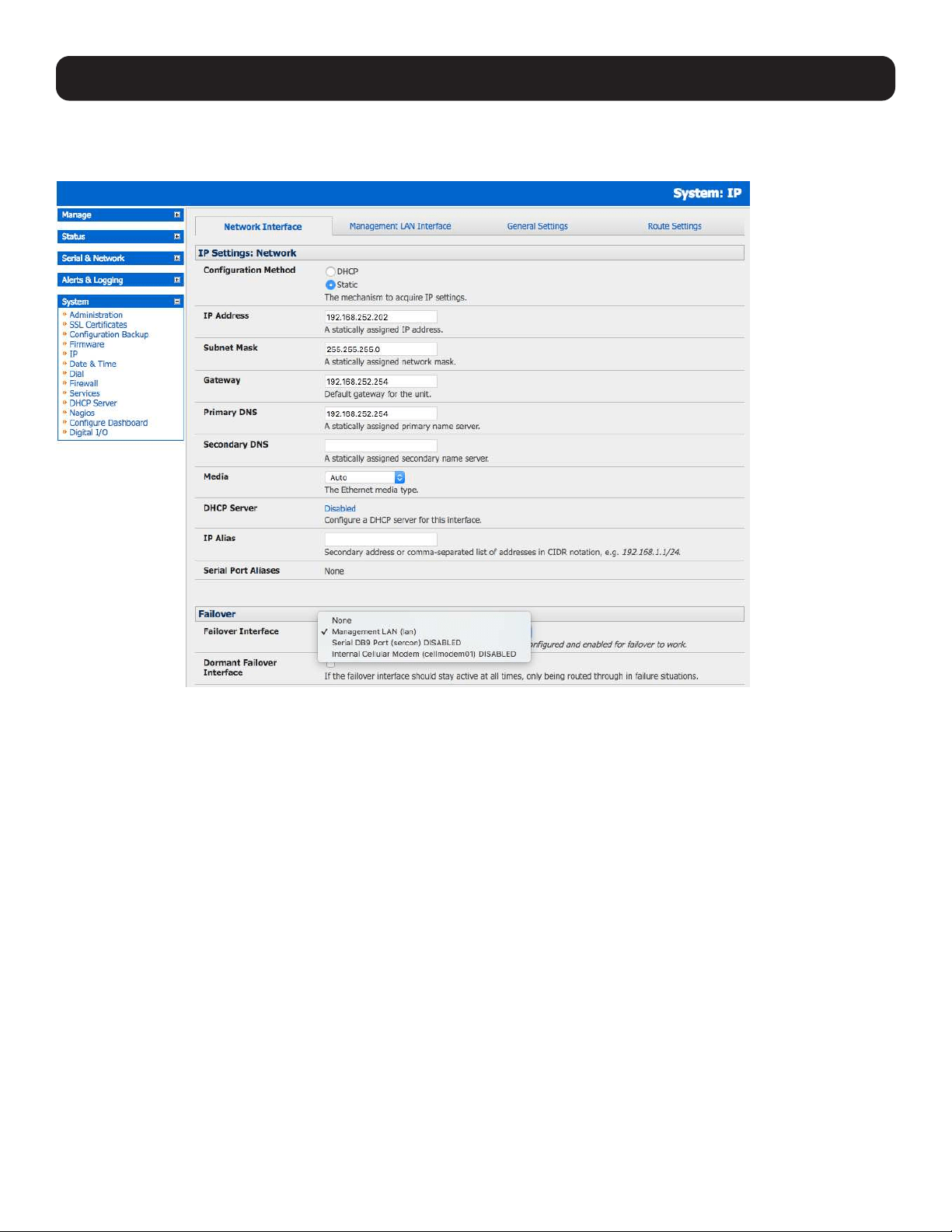
80
5. Firewall, Failover and OOB Access
5.5 Broadband Ethernet Failover
The second Ethernet port on the console servers can also be configured for failover to ensure transparent high availability.
• When configuring the principal network connection, specify Management LAN Interface as the Failover Interface to be
used when a fault has been detected with Network Interface.
• Specify the Probe Addresses of two sites (the Primary and Secondary) that the advanced console server is to ping to
determine if Network Interface is still operational.
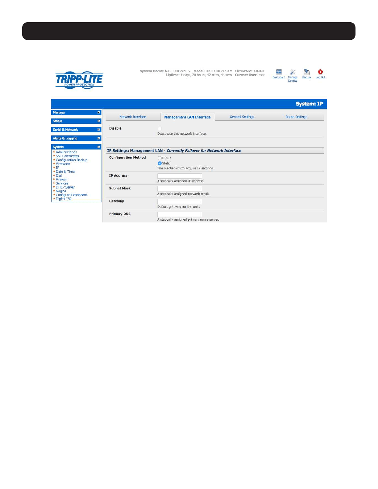
81
• On the Management LAN Interface, configure the IP Address, Subnet Mask and Gateway the same as you used for
Network Interface.
In this mode, Management LAN Interface is available as the transparent back-up port to Network Interface for accessing
the management network. In the event Network Interface becomes unavailable, Management LAN Interface will
automatically and transparently take over the work of Network Interface.
Notes: Only SSH access is enabled on the failover connection. In firmware versions later than 3.0.2, HTTPS access is also enabled so the
administrator can connect to the console server using SSH (or HTTPS) to fix the problem.
By default, the advanced console server supports automatic failure-recovery back to the original state prior to failover (firmware version
3.1.0 and later). The advanced console server continually pings probe addresses while in original and failover states. The original state will
automatically be set as a priority and reestablished following three successful pings of the probe addresses during failover. The failover state
will be removed once the original state has been re-established.
For firmware pre-V3.1.0, the advanced console server does not support automatic failure-recovery back to the original state prior to the
failover. To restore networking to a recovered state, the following command needs to be run:
rm -f /var/run/*-failed-over && config -r ipconfig
If required, you can run a custom bash script when the device fails over. It is possible to use this script to implement automatic failure
recovery, depending on your network setup. The script to create is:
/etc/config/scripts/interface-failover-alert
5.6 Cellular Modem Connection
The B093 and B098 family of advanced console servers support internal cellular modems. These modems first need to be
installed (see section 5.6.1) and then set up to validate they can connect to the carrier network (described in 5.6.4 and
5.6.5). They then can be configured for operation in Always- on cellular router or OOB mode, or in Failover mode (detailed in
next section 5.7).
5. Firewall, Failover and OOB Access
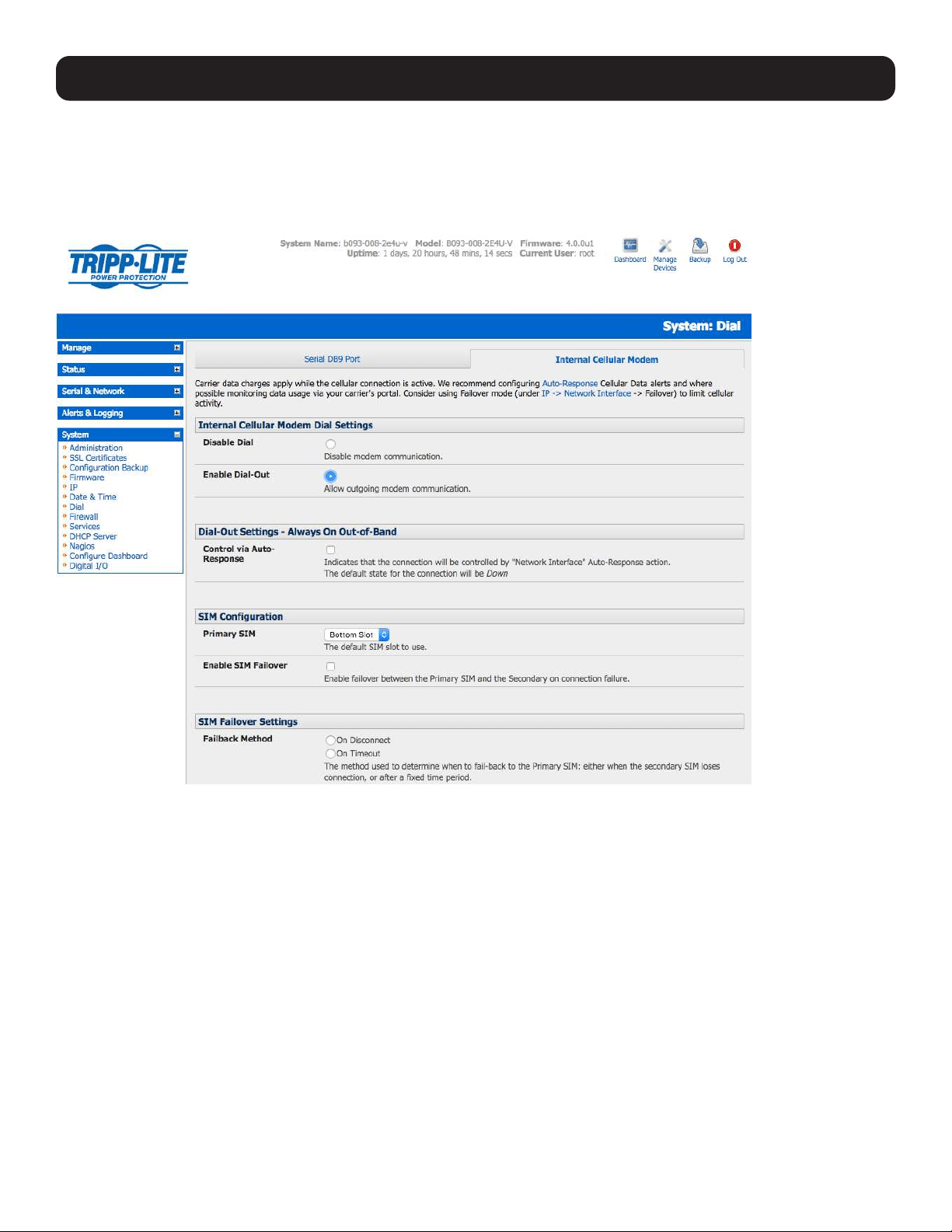
82
5. Firewall, Failover and OOB Access
5.6.1 Connecting to a 4G LTE Carrier Network
Before powering on the console server, install the SIM card provided by your cellular carrier and attach the external aerial.
Select Internal Cellular Modem panel on the System: Dial menu.
Check Enable Dial-Out Settings.
Note: Your 4G LTE carrier may have provided you with details for configuring the connection, including APN (Access Point Name), PIN
Code (optional PIN code which may be required to unlock the SIM card), Phone Number (the sequence to dial to establish the connection,
defaults to *99***1#), Username / Password (optional) and Dial string (optional AT commands). However, you generally will only need to
enter your provider’s APN and leave the other fields blank.
Enter the carrier’s APN—e.g., for AT&T (USA), simply enter i2gold; for T-Mobile (USA), enter epc.tmobile.com; for InterNode
(Aust), enter internode; and for Telstra (Aust), enter telstra.internet
If the SIM card is configured with a PIN code, you will be required to unlock the card by entering the PIN code. If the PIN code
is entered incorrectly three times, the PUK Code will be required to unlock the card.
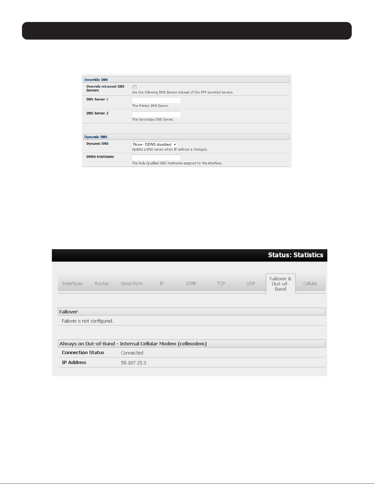
83
You may also need to set Override DNS to use alternate DNS servers from those provided by your carrier.
• To enable Override DNS, check the Override Returned DNS Servers box. Enter the IP of the DNS servers into the spaces
provided.
• Check Apply. A radio connection will be established with your cellular carrier.
5.6.2 Verifying the Cellular Connection
Out-of-band access is enabled by default, so the cellular modem connection should now be on.
• You can verify the connection status from Status: Statistics
o Select the Cellular tab. In Service Availability, verify Mode is set to Online.
o Select Failover & Out-of-Band. The Connection Status should read “Connected”.
o Check your allocated IP address.
• You can measure the received signal strength from the Cellular Statistics page on the Status: Statistics screen. This will
display the current state of the cellular modem, including the Received Signal Strength Indicator (RSSI).
Note: Received Signal Strength Indicator (RSSI) is a measurement of the Radio Frequency (RF) power present in a received radio signal at
the mobile device. It is generally expressed in dBm. The best throughput comes from placing the device in an area with the highest RSSI.
-100 dbm or less = Unacceptable Coverage
-99 dbm to -90 dbm = Weak Coverage
-89 dbm to -70 dbm = Medium to High Coverage
-69 dbm or greater = Strong Coverage
5. Firewall, Failover and OOB Access
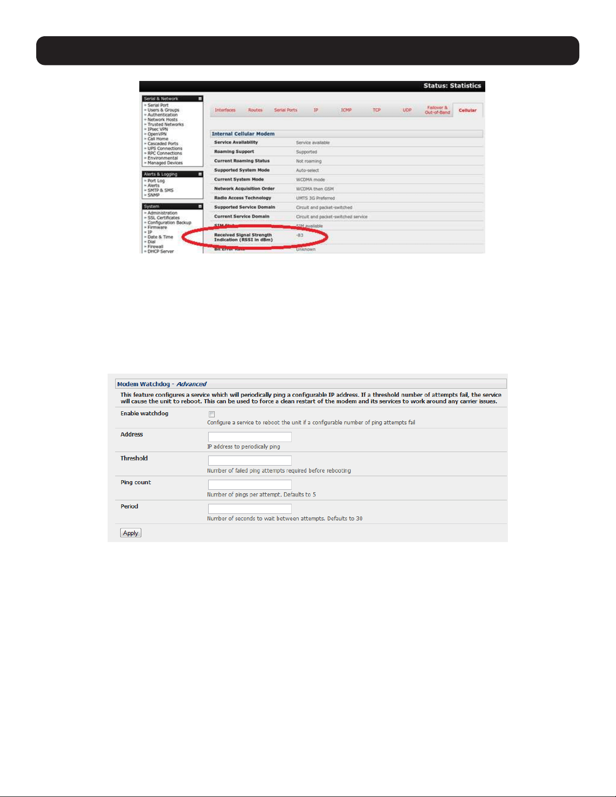
84
5. Firewall, Failover and OOB Access
• With the cellular modem connection on, you can also see the connection status from the LEDs on top of the unit.
5.6.3 Cellular Modem Watchdog
When you select Enable Dial-Out on the System: Dial menu, you will be given the option to configure a cellular modem
watchdog service (with firmware version 3.5.2u13 and later). This service will periodically ping a configurable IP address. If a
set threshold number of consecutive attempts fail, the service will cause the unit to reboot. This can be used to force a clean
restart of the modem and its services to work around any carrier issues.
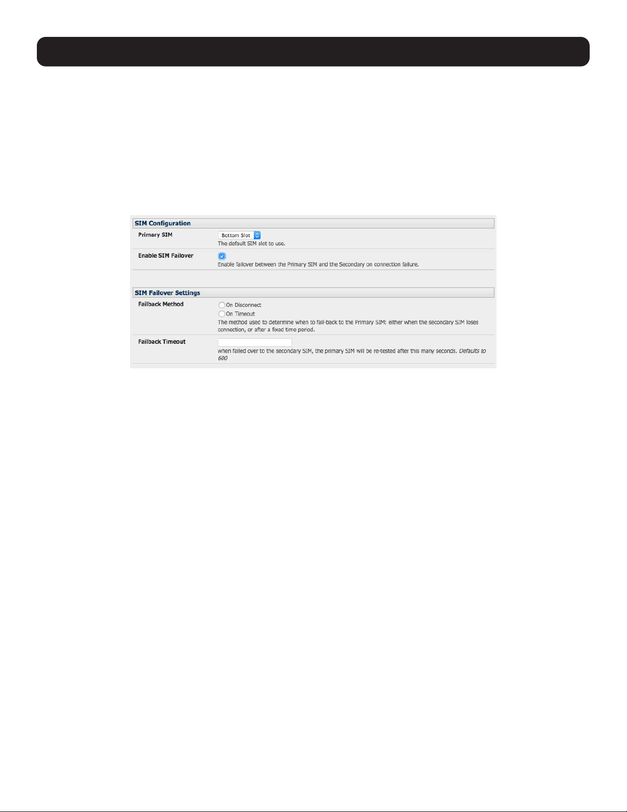
85
5. Firewall, Failover and OOB Access
5.6.4 Dual SIM Failover
Some console server models allow you to insert two SIM cards so you can selectively connect to two carrier networks. The
dual SIM failover feature allows the cell modem to selectively failover to the secondary SIM when communications over the
primary SIM fails.
To configure dual SIM failover, you need to:
• Choose which of the SIMs is to be the Primary, and the other SIM will be the secondary/failover. It is recommended that an
explicit slot is chosen, rather than leaving it on Automatic. Select Internal Cellular Modem panel on the System: Dial
menu nominate which slot (Top or Bottom) contains the Primary.
• Check Enable SIM Failover.
• Specify how the device will Failback from the failover SIM to the Primary SIM. There are two options
o The ‘On Disconnect’ failback option will failback to the Primary SIM only after the connection on the failover SIM has
failed its ping test.
o The ‘On Timeout’ failback option will failback to the Primary SIM after the connection on the failover SIM has been up
for the timeout period. The timeout period is either the default value of 600 seconds if the Failback Timeout field is left
empty or the number of seconds you have specified in the Failback Timeout field.
• Next, you will need to configure each SIM connection with as much information (e.g. APN, etc.), such that it will make a
successful connection, assuming sufficient signal strength from the cell service provider.
• Enter a Failback Test IP address for each SIM. This IP address is used to ping test the status of the cell modem connection
and to determine if SIM failover or failback is to take place.
• Configuring DDNS and the Modem Watchdog are optional. DDNS, when configured, will be applied to the cell modem dial
out connection regardless of which SIM is currently in use. Dual SIM failover is for dial out connections only.
5.6.5 Automatic SIM Slot Detection
If a single SIM card is used in a Dual SIM slot product, the default configuration for the product is to automatically detect
which slot the SIM is in and select that slot. If both slots are populated, the bottom SIM slot will be used in preference.
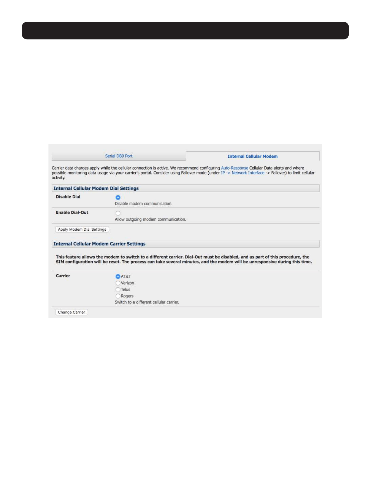
86
5. Firewall, Failover and OOB Access
5.6.6 Multi-Carrier Cellular Support
Some cellular carriers require the console server’s cellular modem to be programmed with carrier-specific firmware to operate
on their network. Some console server models are equipped with a reprogrammable cellular modem, allowing them to operate
on more than one such carrier network.
Note: Changes to the cellular modem firmware are unaffected by Tripp Lite firmware upgrades or factory erase/configuration reset
operations.
To switch carriers using the UI:
• For devices with multi-carrier capability, the System: Dial: Internal Cellular Modem tab provides control over which
carrier’s firmware is installed on the modem.
• Select the desired carrier and click the Change Carrier button to program the modem’s flash with the carrier-specific
firmware image(s).
• The flashing process takes several minutes during which the cellular modem is unavailable. During this time, the page
periodically refreshes with status information. Upon successful completion, the page displays the message: Cellular
Firmware carrier change completed.
Multi-carrier capable models ship with cellular modem firmware for each supported carrier pre-loaded onto internal non-volatile
or USB storage. Periodically, new cellular modem firmware becomes available and is published on the Tripp Lite downloads
site.
Note: If your unit’s cellular connection is operating correctly, there is typically no need to upgrade its cellular firmware.
To download and apply new cellular firmware using the UI:
• For devices with multi-carrier capability, the System: Firmware page shows a second section with local cellular firmware
image status and a button to start the firmware update process.
• The Cellular Firmware Status indicates the date of the last firmware download, and a cryptographic fingerprint that can be
used to verify the local files’ integrity through Tripp Lite Technical Support..
• Click the Check for Update button to step through the upgrade process. This process contacts the remote server and
displays an update summary.
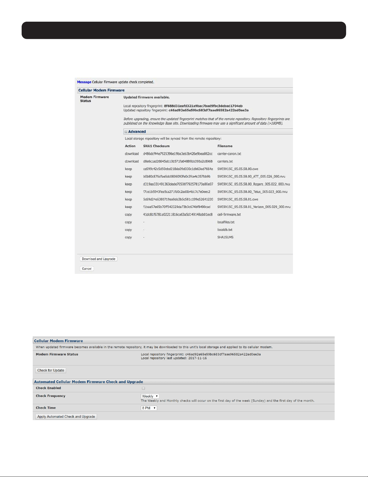
87
5. Firewall, Failover and OOB Access
• The update summary indicates the local and remote fingerprints for comparison, without altering any of the local files. The
Advanced section, when expanded, shows a full list of files to be downloaded or deleted, along with their SHA1 hashes
(temporary files downloaded during the intial Check for Updates check may be listed as simple files to “copy” into place,
as they do not have to be re-downloaded).
• Click Download and Apply to start the update. All files suitable for the modem are downloaded, but the modem will only be
flashed if new firmware is available for the currently selected carrier. Alternatively, click Cancel to reject the update.
• During the download/apply, an interstitial screen is displayed showing Currently upgrading cellular modem firmware.
Once completed, the status of the firmware update is displayed by the System: Firmware page.
• This operation may be automated by enabling the Automatic Cellular Modem Firmware Check and Upgrade option. This
allows the user to schedule these checks on a daily, weekly, or monthly schedule, and specify the time of day that the check
will run. If new firmware is found, the device will automatically download and apply it.

88
5. Firewall, Failover and OOB Access
Advanced users may also control multi-carrier features from the CLI:
• Show currently selected carrier:
cellctl -is | egrep “^preferred-carrier” | cut -d “ “ -f 2
• Show current modem firmware version:
cellctl -is | egrep “^current-firmware” | cut -d “ “ -f 2
• List available carriers supported on installed modem:
/etc/scripts/cell-fw-update -l
• Check for availability of firmware updates:
/etc/scripts/cell-fw-update -u
Output is the remote fingerprint followed by the list of actions that would be taken by cell-fw-update -d.
• Download latest firmware for all carriers supported by the modem:
/etc/scripts/cell-fw-update -d
Also specify -v to show verbose download progress.
• Flash modem with latest local firmware for carrier:
/etc/scripts/cell-fw-update -c <carrier>
where <carrier> is one of the carrier identifiers emitted by cell-fw-update -l. This command can be used to switch carriers or
to update the firmware of the current carrier. If the firmware version information on the modem is identical, the modem may
reject the update without error.
5.7 Cellular Operation
The cellular modem can be set up to connect to the carrier in:
• Cellular router mode. In this mode, the dial-out connection to the carrier cellular network is always on, and IP traffic is
routed between the cellular connected network and the console server’s local network ports. This is the default mode of
operation.
• OOB mode. In this mode, the dial-out connection to the carrier’s cellular network is always on and awaiting incoming
access from a remote site to the console server or attached serial consoles/network hosts.
• Failover mode. In this mode, a dial-out cellular connection is established only in the event of a ping failure.
• Circuit Switched Data (CSD) mode. In this dial-in mode the cellular modem can receive incoming calls from remote
modems who dial a special Data Terminating number. This is a 3G mode only.
5.7.1 Set Up OOB Access
In this mode, the dial-out connection to the carrier cellular network is always on and awaiting any incoming traffic. By default,
the only traffic enabled is incoming SSH access to the console server, its serial ports, and incoming HTTPS access to the
console server. There is a low level of management traffic going over the cellular network. Generally, the status reports and
alerts from the site can be carried over the main network.
This mode is typically used for out-of-band (OOB) access to remote sites. To directly access the Tripp Lite console server, a
public IP address is needed and must not have SSH access firewalled. This OOB mode is the default for Tripp Lite console
servers with internal cellular modems. OOB access is enabled by default and the cellular modem connection is always on.
For direct access, the console server needs to have a public IP address and must not have SSH access firewalled.
Almost all carriers offer corporate mobile data service/plans with a public (static or dynamic) IP address. These plans often
have a service fee attached.
• If you have a static public IP address plan, you can also try accessing the console server using the public IP address provided
by the carrier. By default, only HTTPS and SSH access is enabled on the OOB connection so you can browse to the console
server, but you cannot ping it.
• If you have a dynamic public IP address plan, a DDNS service will need to be configured to enable the remote administrator to
initiate incoming access. Once this is done, you can also try accessing the console server using the allocated domain name.
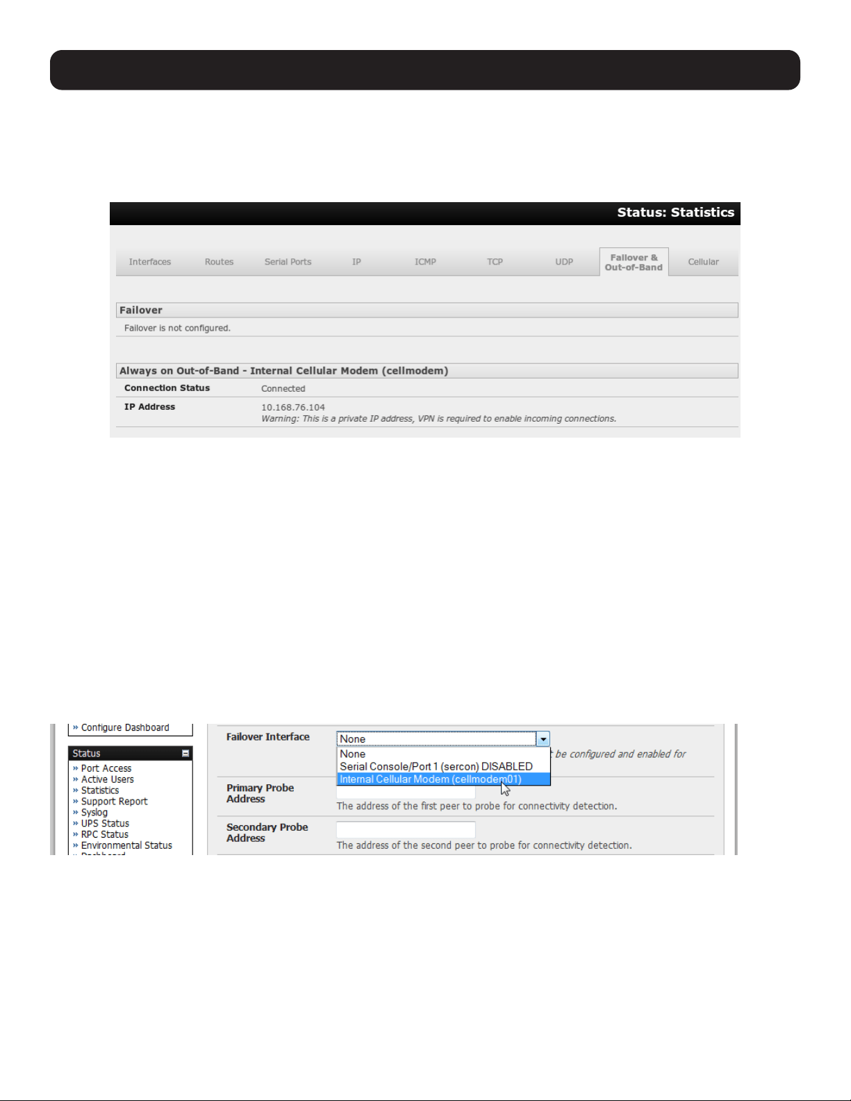
89
By default, most providers offer a consumer grade service, which provides dynamic private IP address assignments to 3G
devices. This IP address is not visible across the Internet, but generally, it is adequate for home and general business use.
• With such a plan, the Failover & Out-of-Band tab on the Status: Statistics will identify that your carrier has allocated
you a private IP address (i.e. in the range 10.0.0.0 – 10.255.255.255, 172.16.0.0 – 172.31.255.255 or 192.168.0.0 –
192.168.255.255).
• For inbound OOB connection, you will need to set up a VPN.
In out-of-band access mode, the internal cellular modem will continually stay connected. The alternative is to set up failover
mode on the console server (detailed in the next section).
5.7.2 Set Up Cellular Failover
In this mode, a dial-out cellular connection is only established in the event of a disruption to the main network. The cellular
connection normally remains idle in a low power state and is only activated in the event of a ping failure. Standby mode is
ideal for remote sites with expensive power or very high cellular traffic costs.
In this mode, the console server continually pings select probe addresses over the main network connection. During a ping
failure, it dials out and sets up a dial-out ppp over the cellular modem and access is switched transparently to this network
connection. When the main network connection is restored, access is switched back.
Once you have configured the carrier connection, the cellular modem can be configured for failover.
This will tell the cellular connection to remain idle in a low power state. If the primary and secondary probe addresses are not
available, it will reestablish the cellular connection and reconnect to the cellular carrier.
• Navigate to the Network Interface on the System: IP menu and specify Internal Cellular modem (cell modem 01) as
the Failover Interface to be used when a fault has been detected.
• Specify the Probe Addresses of two sites (the Primary and Secondary) that the console server is to ping to determine if
the principal network is still operational.
• In event of a failure of the principal network, the cellular network connection is activated as the access path to the console
server (and Managed Devices). Only HTTPS and SSH access is enabled on the failover connection (which should enable the
administrator to connect and fix the problem).
5. Firewall, Failover and OOB Access
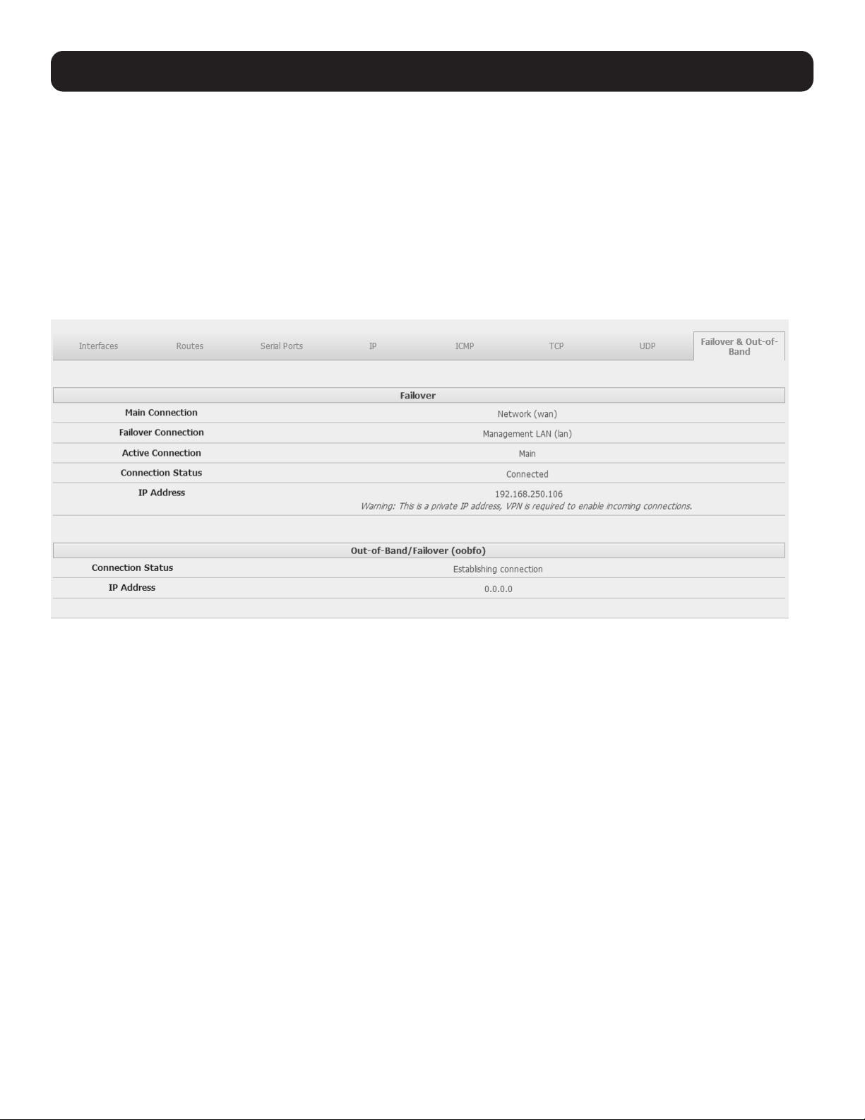
90
Note: By default, the advanced console server supports automatic failure-recovery back to the original state prior to failover (firmware
version 3.1.0 and later). The advanced console server continually pings probe addresses while in original and failover states. The original
state will automatically be set as a priority and reestablished following three successful pings of the probe addresses during failover. The
failover state will be removed once the original state has been re-established.
For earlier firmware that does not support automatic failure-recovery, restore networking to a recovered state by running the following
command:
rm -f /var/run/*-failed-over && config -r ipconfig
If required, you can run a custom bash script when the device fails over. It is possible to use this script to implement automatic failure
recovery, depending on your network setup. The script to create is:
/etc/config/scripts/interface-failover-alert
• You can check the connection status by selecting the Cellular panel on the Status: Statistics menu.
o The operational status will change as the cellular modem finds a channel and connects to the network.
o The Failover & Out-of-Band screen will display information relating to a configured Failover/OOB interface and the status
of that connection. The IP address of the Failover / OOB interface will be presented in the Failover & Out-of-Band screen
once the Failover/OOB interface has been triggered.
5.7.3 Cellular Routing
Once you have configured the carrier connection, the cellular modem can be configured to route traffic through the console
server. This requires setting up forwarding and masquerading (refer to 5.8 Firewall and Forwarding).
5. Firewall, Failover and OOB Access
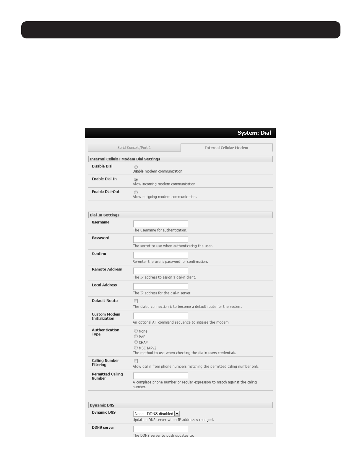
91
5.7.4 Set Up Cellular CSD Dial-In
Once you have configured the carrier connection, the cellular modem can be configured to receive Circuit Switched Data
(CSD) calls.
Note: CSD is a legacy form of data transmission developed for the TDMA-based mobile phone systems like GSM. CSD uses a single radio
time slot to deliver 9.6kb/s data transmission to the GSM Network and Switching Subsystem, where it could be connected through the
equivalent of a normal modem to the Public Switched Telephone Network (PSTN) an allow direct calls to any dial-up service. CSD is provided
selectively by carriers. As such, it is important you receive a Data Terminating number as part of the mobile service your carrier provides. This
is the number that external modems will call to access the console server.
• Select the Cellular Modem panel on the System: Dial menu.
• Check Enable Dial-In and configure the Dial-In Settings.
5. Firewall, Failover and OOB Access

92
5. Firewall, Failover and OOB Access
5.8 Firewall and Forwarding
Tripp Lite console servers with version 3.3 firmware (and later) have basic routing, NAT (Network Address Translation), packet
filtering and port forwarding support on all network interfaces. This enables the console server to function as an Internet or
external network gateway, via cellular connections or other Ethernet networks on two Ethernet port models:
• Network Forwarding allows the network packets on one network interface (i.e. LAN1 / eth0) to be forwarded to another
network interface (i.e. LAN2/eth1 or dial-out/cellular). Locally networked devices can IP connect through the console server
to devices on remote networks.
• IP Masquerading is used to allow all devices on your local private network to hide behind and share one public IP address
when connecting to a public network. This type of translation is only used for connections originating within the private
network destined for the outside public network. Each outbound connection is maintained using a different source IP port
number.
When using IP masquerading, devices on the external network cannot initiate connections to devices on the internal
network. Port Forwards allow external users to connect to a specific port on the external interface of the console server and
be redirected to a specified internal address for a device on the internal network.
• With Firewall Rules, packet filtering inspects each packet passing through the firewall and accepts or rejects it based on
user-defined rules.
• Then Service Access Rules can be set for connecting to the console server/router itself.
5.8.1 Configuring Network Forwarding and IP Masquerading
To use a console server as an Internet or external network gateway requires establishing an external network connection, then
enabling forwarding and masquerading functions.
Note: Network forwarding allows the network packets on one network interface (i.e. LAN1 / eth0) to be forwarded to another network
interface (i.e. LAN2/eth1 or dial-out/cellular) so locally networked devices can IP connect through the console server to devices on a remote
network. IP masquerading is used to allow all the devices on your local private network to hide behind and share one public IP address when
connecting to a public network. This type of translation is only used for connections originating within the private network destined for the
outside public network, and each outbound connection is maintained by using a different source IP port number.
By default, all console server models are configured so they will not route traffic between networks. To use the console server
as an Internet or external network gateway, forwarding must be enabled so traffic can be routed from the internal network to
the Internet/external network.
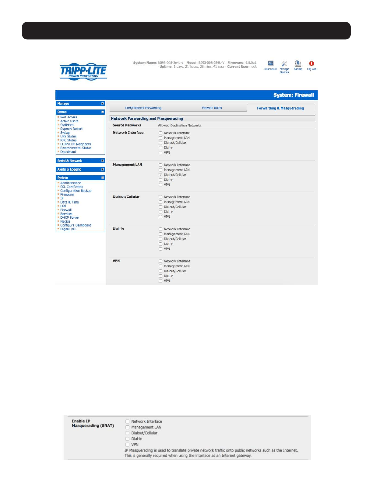
93
5. Firewall, Failover and OOB Access
• Navigate to the System: Firewall page, then click on the Forwarding & Masquerading tab.
• Find the Source Network to be routed, then select the relevant Destination Network to enable Forwarding.
For example, to configure a single Ethernet device as a cellular router:
• The Source Network would be the Network Interface and the Destination Network would be Dial-Out/Cellular.
IP masquerading is generally required if the console server will be routed to the Internet or if the external network it is being
routed to does not have routing information about the internal network behind the console server.
IP masquerading performs Source Network Address Translation (SNAT) on outgoing packets to make them appear as if they
are from the console server (rather than devices on the internal network). When response packets come back to devices on
the external network, the console server will translate the packet address back to the internal IP so that it is routed correctly.
This allows the console server to provide full outgoing connectivity for internal devices using a single IP address on the external
network.
By default, IP masquerading is disabled for all networks. To enable masquerading:
• Select Forwarding & Masquerading panel on the System: Firewall menu.
• Check Enable IP Masquerading (SNAT) on the network interfaces where masquerading is to be enabled.
Masquerading is typically applied to any interface that is connecting with a public network such as the Internet.
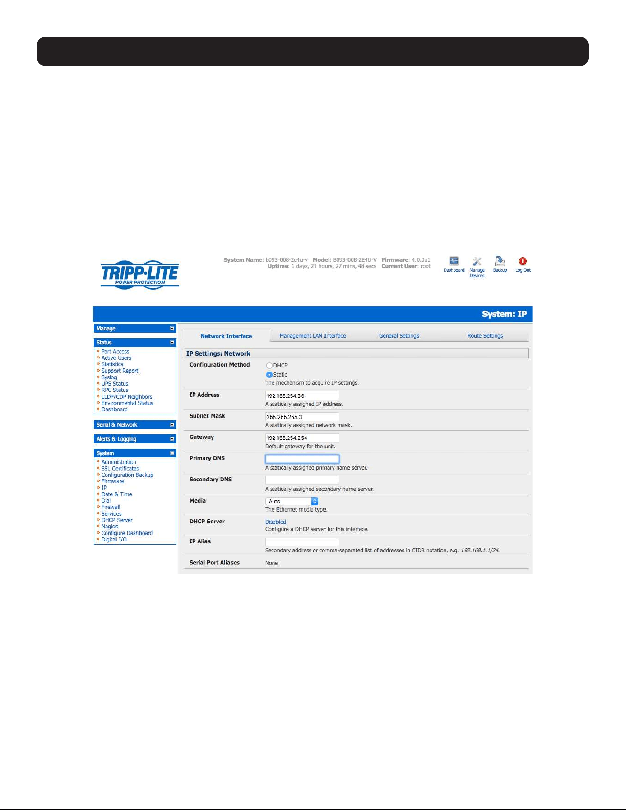
94
5. Firewall, Failover and OOB Access
5.8.2 Configuring Client Devices
Client devices on the local network must be configured with Gateway and DNS settings. This can be done statically on each
device or using DHCP.
Manual Configuration
Manually set a static gateway address (the address of the console server) and set the DNS server address to be the same as
used on the external network. If the console server is acting as an internet gateway or a cellular router, use the ISP provided
DNS server address.
DHCP Configuration
• Navigate to the System: IP page.
• Click the tab of the interface connected to the internal network. To use DHCP, a static address must be set. Check that the
static IP and subnet mask fields are set.
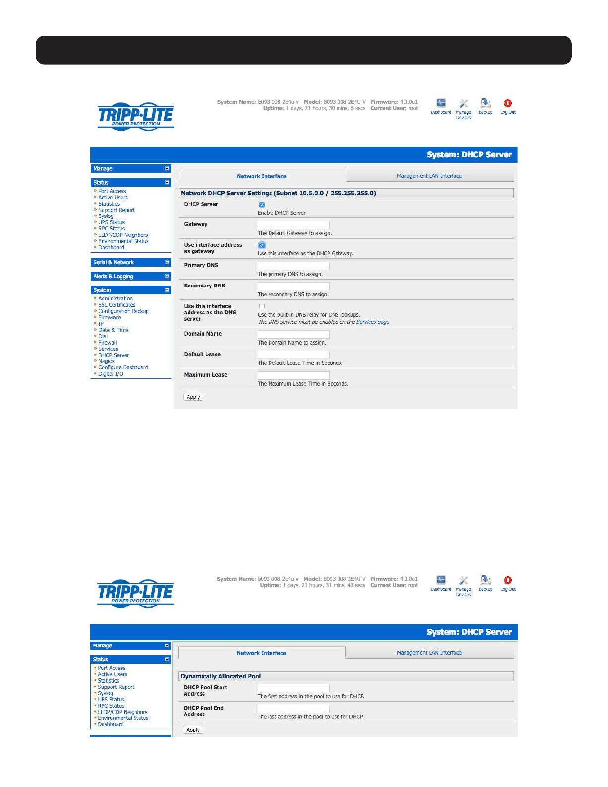
95
• Click on the Disabled link next to DHCP Server, which will open the System: DHCP Server page.
• Check Enable DHCP Server.
• To configure the DHCP server, select the Use interface address as gateway check box.
• Set the DNS server address(es) to be the same as used on the external network. If the console server is acting as an
internet gateway or a cellular router, then use the ISP provided DNS server address
• Enter the Default Lease time and Maximum Lease time in seconds. The lease time is the time that a dynamically
assigned IP address is valid before the client must request it again.
• Click Apply.
The DHCP server will sequentially issue IP addresses from a specified address pool(s):
• Click Add in the Dynamic Address Allocation Pools field.
• Enter the DHCP Pool Start Address and End Address. Click Apply.
5. Firewall, Failover and OOB Access
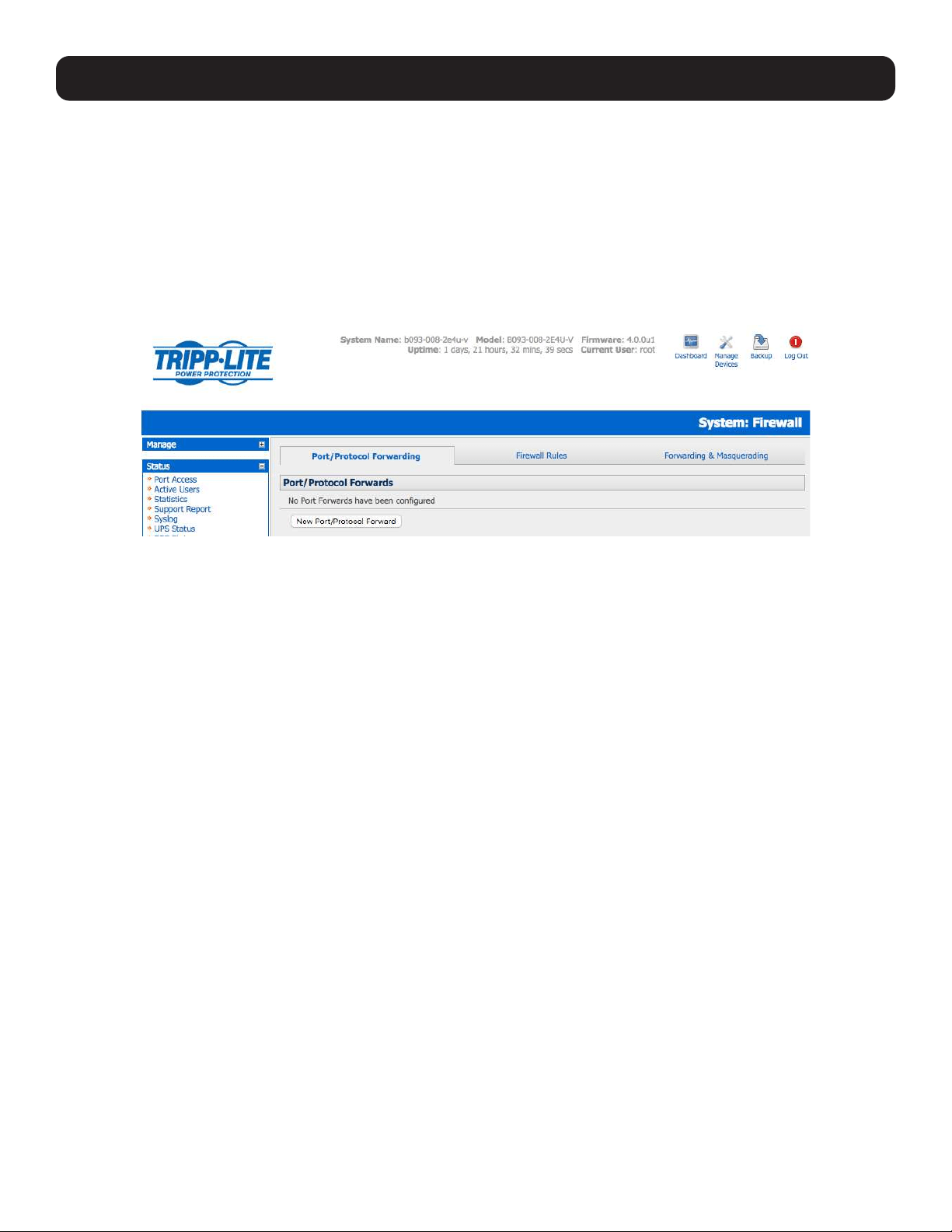
96
5. Firewall, Failover and OOB Access
The DHCP server also supports pre-assigning IP addresses to be allocated only to specific MAC addresses and reserving IP
addresses to be used by connected hosts with fixed IP addresses.
Once applied, devices on the internal network will be able to access resources on the external network.
5.8.3 Port / Protocol Forwarding
When using IP masquerading, devices on the external network cannot initiate connections to devices on the internal network.
To work around this, port forwarding can be set up to allow external users to connect to a specific port or range of ports on
the external interface of the console server/cellular router. The console server/cellular router redirects the data to a specified
internal address and port range.
To set up a port/protocol forward:
• Navigate to the System: Firewall page and click on the Port Forwarding tab.
• Click Add New Port Forward.
• Fill in the following fields:
Name: Name for the port forward. This should describe the target and the service that the
port forward is used to access.
Input Interface: This allows the user to only forward the port from a specific interface. In most
cases, this should be left as “Any”.
Source Address/Address Range: This allows the user to restrict access to a port forward to a specific source IP
address or IP address range of the data. This may be left blank. IP address ranges
use the format ip/netmask (where netmask is in bits 1-32).
Destination Address/Address Range: The destination IP address/address range to match. This may be left blank. IP
address ranges use the format ip/netmask (where netmask is in bits 1-32).
Input Port Range: The range of ports to forward to the destination IP. These will be the port(s)
specified when accessing the port forward. These ports do not need to be the same
as the output port range.
Protocol: The protocol of the data being forwarded. The options are TCP or UDP, TCP and
UDP, ICMP, ESP, GRE and Any.
Output Address: The target of the port forward. This is an address on the internal network where
packets sent to the Input Interface on the input port range are sent.
Output Port Range: The port or range of ports that the packets will be redirected to on the Output
Address. Ranges use the format start-finish. This option is only valid for TCP and
UDP protocols.
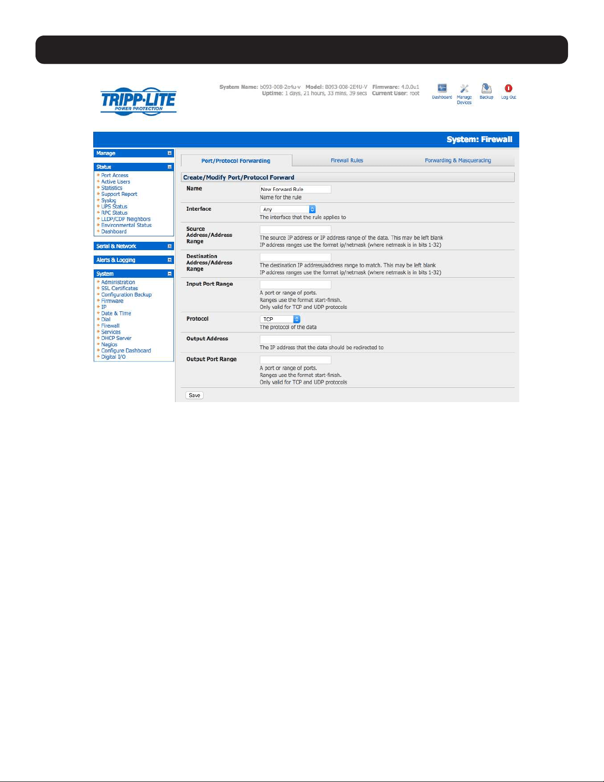
97
5. Firewall, Failover and OOB Access
For example, to forward port 8443 to an internal HTTPS server on 192.168.10.2, the following settings are used:
Input Interface: Any
Input Port Range: 8443
Protocol: TCP
Output Address: 192.168.10.2
Output Port Range: 443
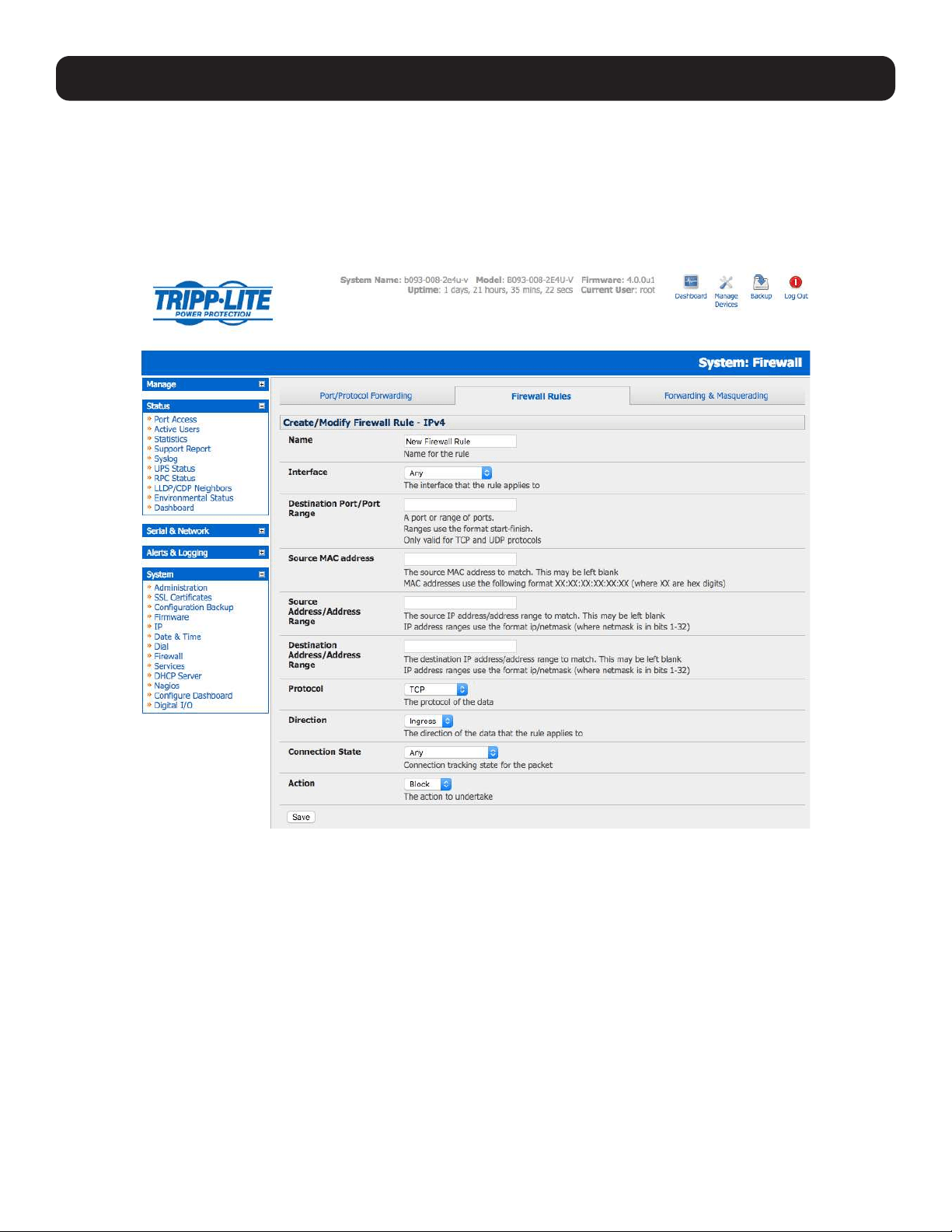
98
5. Firewall, Failover and OOB Access
5.8.4 Firewall Rules
Firewall rules can be used to block or allow traffic through an interface based on port number, the source and/or destination IP
address (range), the direction (ingress or egress) and the protocol. This can be used to allow custom on-box services, or block
traffic based on policy.
To set up a firewall rule:
• Navigate to the System: Firewall page and click on the Firewall Rules tab.
Note: Prior to firmware version 3.4, this tab was labeled Port Rules and fewer firewall rules could be configured.
• Click New Firewall Rule.
• Fill in the following fields:
Name Name the rule. This name should describe the firewall rule policy being implemented (e.g., block
ftp, Allow Tony).
Interface Select the interface the firewall rule will be applied to (i.e. Any, Dial-Out/Cellular, VPN, Network
Interface, Dial-in etc).
Port Range Specify the Port or range of Ports (e.g. 1000 – 1500) the rule will apply to. This may be left blank.
Source MAC Address Specify the source MAC address to be matched. This may be left blank. MAC addresses use the
format XX:XX:XX:XX:XX:XX, where XX are hex digits.
Source Address Range Specify the source IP address (or address range) to match. IP address ranges use the format ip/
netmask (where netmask is in bits 1-32). This may be left blank.
Destination Range Specify the destination IP address/range to match. IP address ranges use the format ip/netmask
(where netmask is in bits 1-32). This may be left blank.
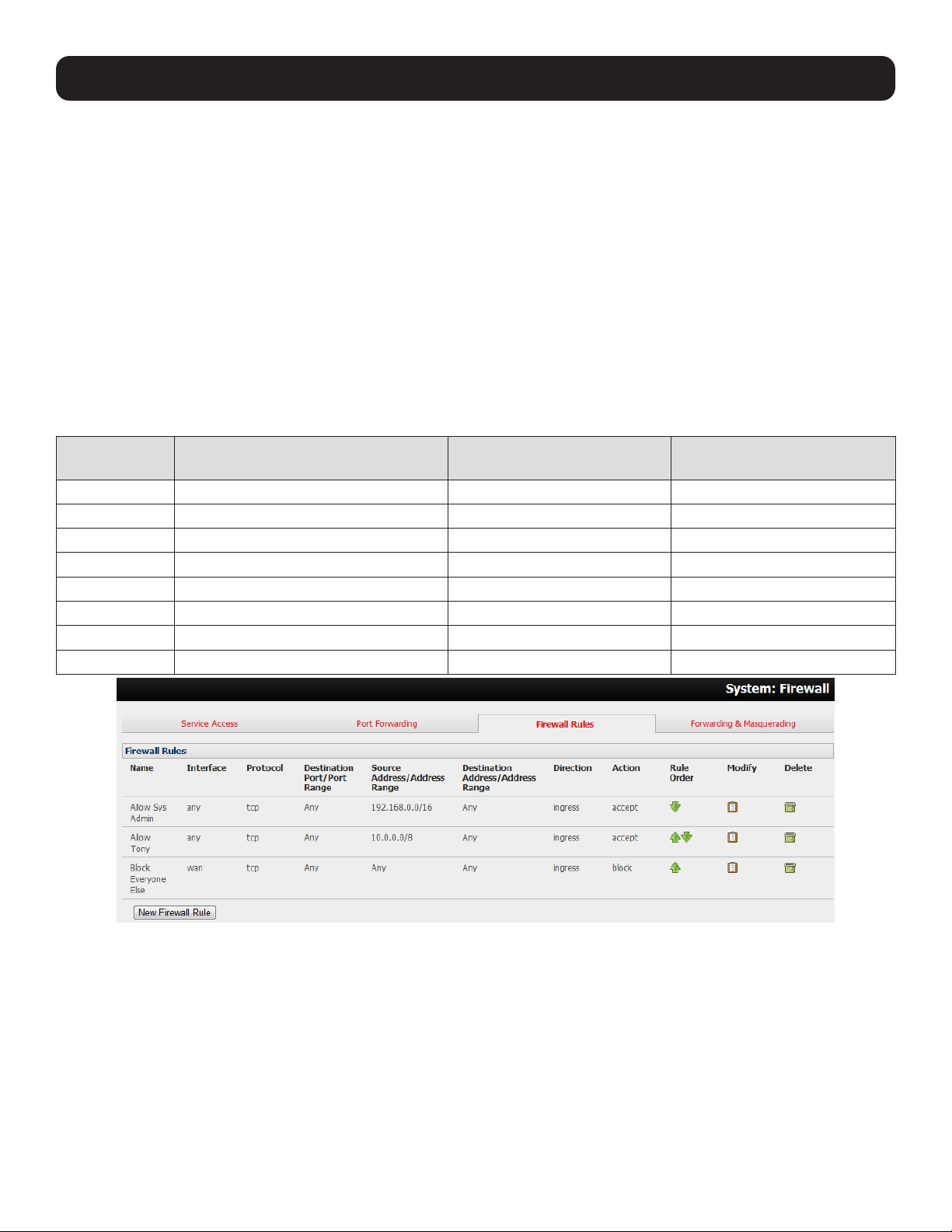
99
5. Firewall, Failover and OOB Access
Protocol Select if the firewall rule will apply to TCP or UDP, TCP and UDP, ICMP, ESP, GRE or Any.
Direction Select the traffic direction the firewall rule will apply to (Ingress = incoming, or Egress).
Action Select the action (Accept or Block) that will be applied to the detected packets that match the
Interface + Port Range + Source/Destination Address Range + Protocol + Direction.
For example, to block all SSH traffic from leaving Dial-Out Interface, the following settings can be used:
Interface: Dial-Out/Cellular
Port Range: 22
Protocol: TCP
Direction: Egress
Action: Block
Firewall rules are processed in a set order- from top to bottom. As such, rule placement is important. For example, with
the following rules, all incoming traffic over the Network Interface is blocked, except when it comes from two assigned IP
addresses (SysAdmin and Tony):
To allow all incoming traffic on all
interfaces from the SysAdmin:
To allow all incoming traffic
from Tony:
To block all incoming traffic
from the Network Interface:
Interface Any Any Network Interface
Port Range Any Any Any
Source MAC Any Any Any
Source IP IP address of SysAdmin IP address of Tony Any
Destination IP Any Any Any
Protocol TCP TCP TCP
Direction Ingress Ingress Ingress
Action Accept Accept Block
However, if the above Rule Order changed so the “Block Everyone Else” rule was second on the list, then the incoming traffic
over the network interface from Tony would be blocked.

100
5. Firewall, Failover and OOB Access
5.8.5 Packet State Matching in Firewall Rules
As of firmware version 4.0.0, firewall rules can include packet state matching. This is implemented using an iptables
extension module and can be set as follows:
Navigate to System > Firewall > Firewall Rules.
In either the IPv4 or IPv6 section, click the New Firewall Rule button.
Enter a Name for the new rule in the Name field.
Select the interface the new rule will be applied against from the Interface pop-up menu.
Note: the available interfaces vary depending on the exact hardware available on the console server. By default, new firewall rules are
applied against Any (i.e. all) available interface.
If the selected interface operates the TCP or UDP protocol, enter a port or port range of the rule’s destination.
If the firewall rule is to apply against a particular MAC address, enter this value in the Source MAC address field. MAC
addresses must be entered in standard xx:xx:xx:xx:xx:xx format (where each xx is a hexadecimal value).
If the firewall rule is to apply against a particular source address or range of source addresses, enter this address or address
range in the Source Address/Address Range field. Address ranges can be entered using the ip-address/netmask syntax.
If the firewall rule is to apply to a particular destination address or address range, enter this address or address range in the
Destination Address/Address Range field. As with the Source Address/Address Range field, address ranges can be entered
using the ip-address/netmask syntax.
Set the data protocol against which firewall rule will apply. By default, new firewall rules apply against the TCP protocol.
Set the direction of data travel against which firewall rule will apply. This setting can take one of two values: Ingress or Egress.
The default is Ingress. Ingress means data arriving at an interface from elsewhere. Egress means data leaving an interface and
going to elsewhere.
Select the desired packet state to match against from the Connection State pop-up menu. Available options are New,
Established/Related and Any. The default option is Any.
Note: The default option leaves packet state matching inactive. With this option, no extra specifications are added to the firewall rule.
Select the desired action to be taken regarding packets of the chosen state from the Action pop-up menu. The two available
options are Block and Accept. The default action is Block.
Click the Save button. Using the Connection State pop-up menu in System > Firewall > Firewall Rules > IPv4 > New
Firewall Rule to set packet state matching to New or Established/Related is equivalent to running one of the following at a
shell-prompt:
# iptables -m state --state NEW
# iptables -m state --state \
ESTABLISHED,RELATED
For example:
# iptables -I INPUT -p tcp --dport 23 -m state --state \
ESTABLISHED,RELATED -j ACCEPT
This tells the firewall to accept incoming Telnet traffic for previously established Telnet sessions.
If the rule is created in IPv6 > New Firewall Rule, it is the equivalent of running one of the following at a shell-prompt:
# ip6tables -m state --state NEW
# ip6tables -m state --state ESTABLISHED,RELATED
For example:
# ip6tables -I INPUT -p tcp --dport 23 -m state --state \
ESTABLISHED,RELATED -j ACCEPT
As with the iptables example, this tells the firewall to accept incoming telnet traffic for previously established telnet sessions.
For more on iptables, ip6tables and iptables-extensions, see the respective man pages: iptables, ip6tables and iptables-
extensions.
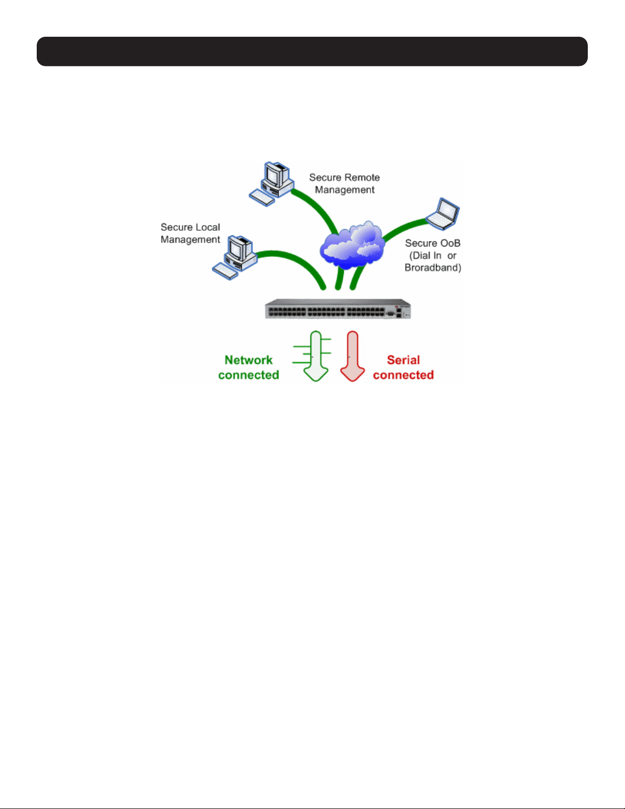
101
6. SSH Tunnels and SDT Connector
Each console server has an embedded SSH server and uses SSH tunneling so remote users can securely connect through the
console server to managed devices by using text-based console tools (e.g., SSH, telnet, SoL), or graphical tools (e.g., VNC,
RDP, HTTPS, HTTP, X11, VMware, DRAC, iLO).
The managed devices being accessed can be located on the same local network as the console server, or they can be
attached to the console server via serial port. The remote User/Administrator connects to the console server by way of SSH
tunnel using a dial-up, wireless or ISDN modem, broadband Internet connection, enterprise VPN or local network connection.
To set up the secure SSH tunnel from the client PC to the console server, you must install and launch SSH client software on
the User/Administrator PC. Tripp Lite recommends you use the SDT Connector client software supplied with the console server
for this task. SDT Connector is simple to install and auto-configure and will provide all users with point-and-click access to all
systems and devices in the secure network. With one click, SDT Connector sets up a secure SSH tunnel from the client to
the selected console server, establishes a port forward connection to the target network-connected host or serial connected
device, and executes the client application used in communicating with the host.
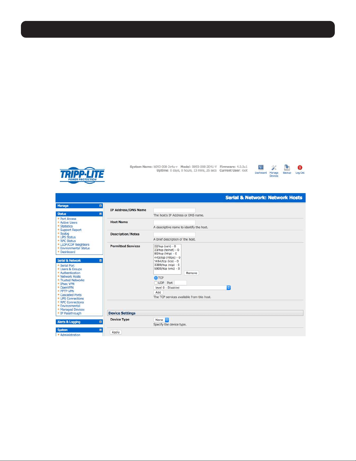
102
6. SSH Tunnels and SDT Connector
6.1 Configuring for SSH Tunneling to Hosts
To set up the console server for SSH tunneled access a network attached host:
• Add the new host and the permitted services using the Serial & Network: Network Hosts menu as detailed in section 4.4
Network Hosts. Only these permitted services will be forwarded by SSH to the host. All other services (TCP/UDP ports) will
be blocked.
Note: Some TCP Ports used by SDT in the console server include:
22 SSH (All SDT tunneled connections)
23 Telnet on local LAN (forwarded inside tunnel)
80 HTTP on local LAN (forwarded inside tunnel)
3389 RDP on local LAN (forwarded inside tunnel)
5900 VNC on local LAN (forwarded inside tunnel)
73XX RDP over serial from local LAN – where XX is the serial port number (i.e. 7301 to 7348 on a 48-port console server)
79XX VNC over serial from local LAN – where XX is the serial port number
• Add new Users using the Serial & Network: Users & Groups menu as detailed in 4.4 Network Hosts. Users can
be authorized to access the console server ports and specified network-attached hosts. To simplify configuration, the
Administrator can first set up Groups with group access permissions, then assign Users to those Group(s).
6.2 SDT Connector Client Configuration
The SDT Connector client works with all Tripp Lite console servers. Each of these remote console servers have an embedded
OpenSSH-based server, which can be configured to port forward connections from the SDT Connector client to hosts on
their local network, as detailed in the previous chapter. The SDT Connector can also be pre-configured with access tools and
applications available to be run when access to a particular host has been established.
SDT Connector can connect to the console server using alternate OOB access. It can also access the console server itself and
access devices connected to serial ports on the console server.
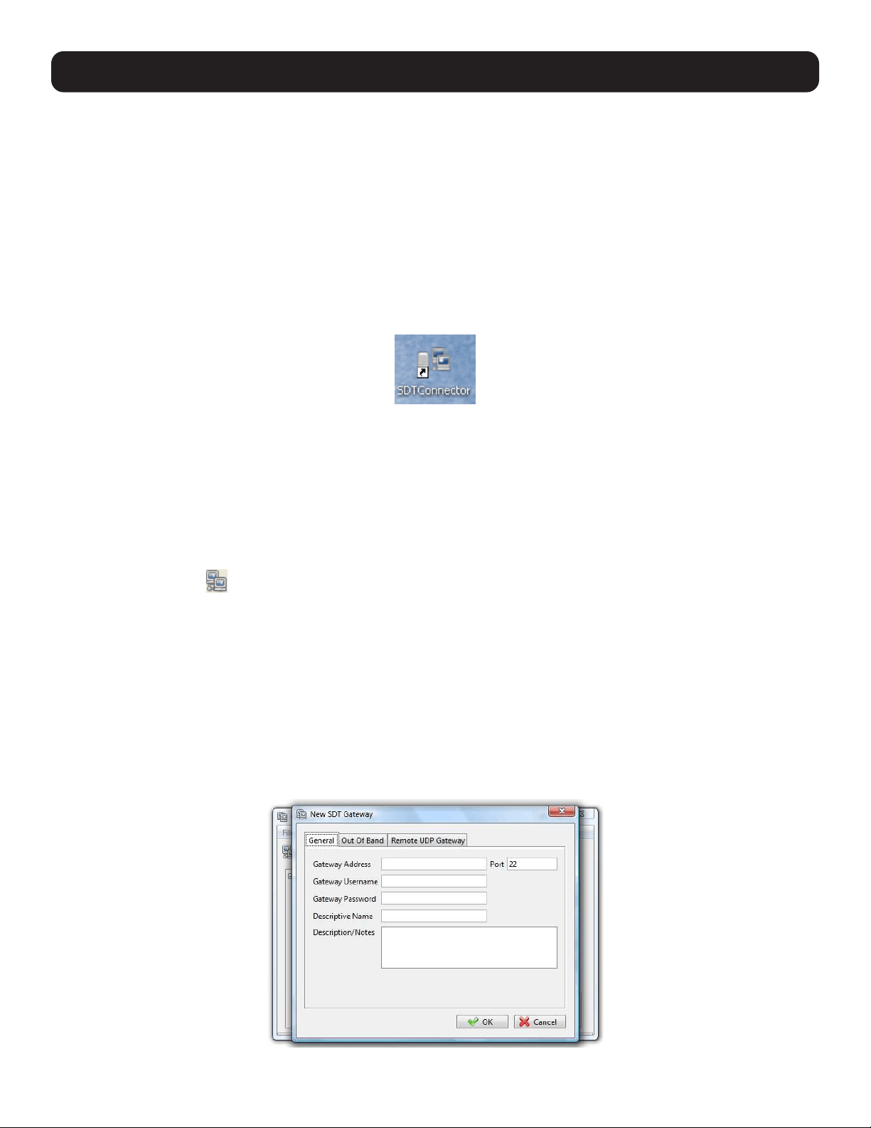
103
6.2.1 SDT Connector Client Installation
The SDT Connector set up program (SDTConnector Setup-1.n.exe or sdtcon-1.n.tar.gz) is included on the CD supplied with
your Tripp Lite console server product.
Run the set-up program.
Note: For Windows clients, the SDTConnectorSetup-1.n.exe application will install the SDT Connector 1.n.exe and the config file defaults.
xml. If there is already a config file on the Windows PC, then it will not be overwritten. To remove the earlier config file, run the regedit
command and search for “SDT Connector”, then remove the directory with this name.
For Linux and other UNIX clients, SDTConnector.tar.gz application will install the sdtcon-1.n.jar and the config file
defaults.xml.
Once the installer completes, you will have a working SDT Connector client installed on your machine and an icon on your
desktop:
Click the SDT Connector icon on your desktop to start the client.
Note: SDT Connector is a Java application, so it must have a Java Runtime Environment (JRE) installed. It will install on Windows 2000
and later and on most Linux platforms. Solaris platforms are also supported. However, they must have Firefox installed. SDT Connector can
run on any system with Java 1.4.2 and above installed, but it assumes the web browser is Firefox, and that xterm -e telnet opens a telnet
window.
6.2.2 Configuring a New Gateway in the SDT Connector Client
To create a secure SSH tunnel to a new console server:
• Click the New Gateway
icon or select the File: New Gateway menu option.
• Enter the IP or DNS Address of the console server and the SSH port that will be used (typically 22).
Note: If SDT Connector is connecting to a remote console server through the public Internet or routed network you will need to:
• Determine the public IP address of the console server (or of the router / firewall that connects the console server to the Internet) as
assigned by the ISP. One way to find the public IP address is to access / or / from a computer on the same network as the console server
and note the reported IP address.
• Set port forwarding for TCP port 22 through any firewall/NAT/router located between SDT Connector and the console server so it points to
the console server. For port forwarding instructions for a range of routers, visit http://www.portforward.com. Also, you can use the Open
Port Check tool at http://www.canyouseeme.org to check whether port forwarding through local firewall/NAT/router devices has been
properly configured.
• Enter the Username and Password of a user on the gateway that has been enabled to connect via SSH and/or create SSH
port redirections.
6. SSH Tunnels and SDT Connector
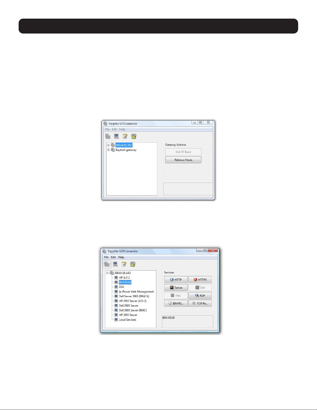
104
6. SSH Tunnels and SDT Connector
• Optionally, enter a Descriptive Name to display, instead of the IP or DNS address, and any Notes or a Description of this
gateway (such as its firmware version, site location or anything special about its network configuration).
• Click OK and an icon for the new gateway will now appear in the SDT Connector home page.
Note: For an SDT Connector user to access a console server (and access specific hosts or serial devices connected to that console server),
that user must first be set up on the console server, and must be authorized to access the specific ports / hosts (refer to 5. Firewall,
Failover and OOB Access). Only these permitted services will be forwarded by SSH to the Host. All other services (TCP/UDP ports) will be
blocked.
6.2.3 Auto-Configure SDT Connector Client with the User’s Access Privileges
Each user on the console server has an access profile configured with access privileges to specific connected hosts and serial
port devices. This configuration can be auto-uploaded into the SDT Connector client:
• Click on the new gateway icon and select Retrieve Hosts. This will:
o Configure access to network-connected hosts the user is authorized to access and set up (for each of these Hosts), the
services (e.g. HTTPS, IPMI2.0) and the related IP ports being redirected.
o Configure access to the console server itself (this is displayed as a Local Services host).
o Configure access with the enabled services for the serial port devices connected to the console server.
Note: The Retrieve Hosts function auto-configures all user classes (i.e. they can be members of user or admin or some other group or no
group). The SDT Connector will not auto-configure the root; it is recommended the account only be used for initial configuration and for
adding an initial Administrator account to the console server.
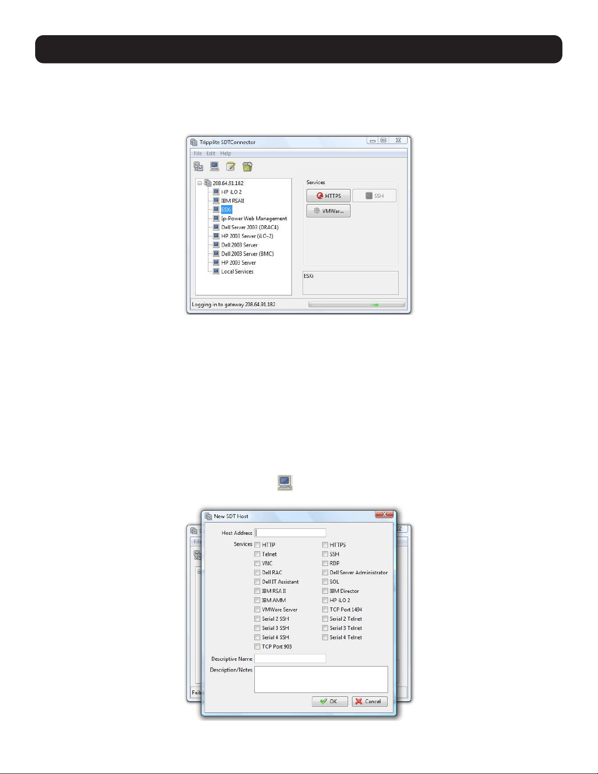
105
6. SSH Tunnels and SDT Connector
6.2.4 Make an SDT Connection Through the Gateway to a Host
Simply point at the host to be accessed, and click on the service to be used in accessing that host. The SSH tunnel to the
gateway is automatically established, the appropriate ports redirected through to the host and the appropriate local client
application is launched pointing at the local endpoint of the redirection:
Note: The SDT Connector client can be configured with an unlimited number of gateways. Each gateway can be configured to port forward
an unlimited number of locally networked hosts. Similarly, there is no limit on the number of SDT Connector clients who can be configured
to access the gateway. Nor are there limits on the number of host connections that an SDT Connector client can concurrently have open
through the one gateway tunnel.
There is a limit on the number of SDT Connector SSH tunnels that can be open at the same time on a particular gateway. Tripp Lite
console servers support at least 50 concurrent connections. For example, a site with a Tripp Lite gateway can have up to 50 users securely
controlling an unlimited number of network attached computers and devices (servers, routers, etc.) at that site, at any time.
Tripp Lite console servers support hundreds of simultaneous client tunnels.
6.2.5 Manually Adding Hosts to the SDT Connector Gateway
For each gateway, you can manually specify the network-connected hosts accessed through that console server. For each
host, specify the services used in communicating with the host.
• Select the newly added gateway and click the host icon
to create a host that is accessible via the gateway. Alternately,
you can select File: New Host.
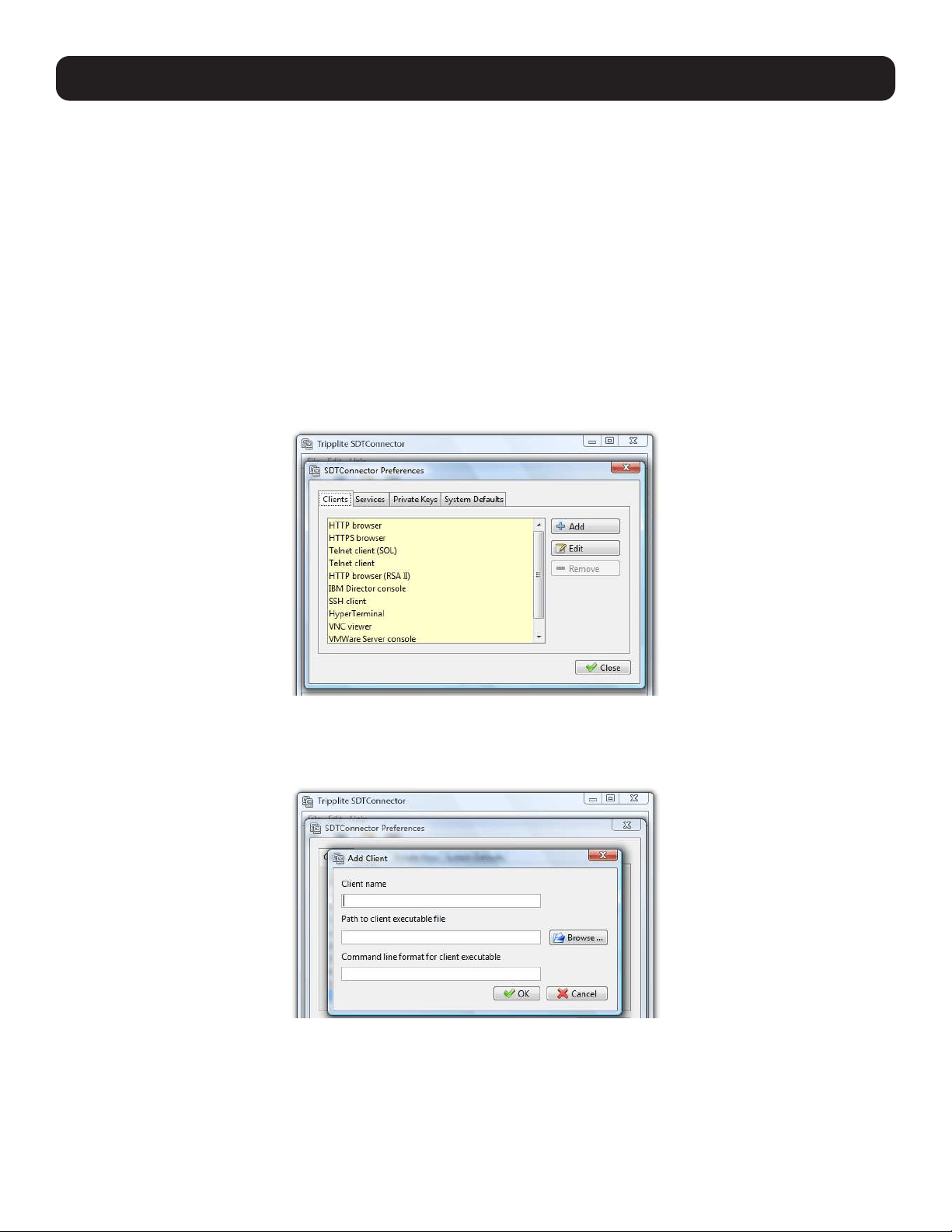
106
6. SSH Tunnels and SDT Connector
• Enter the IP or DNS Host Address (if this is a DNS address, it must be resolvable by the gateway).
• Select which Services are to be used in accessing the new host. A range of service options are pre-configured in the default
SDT Connector client (RDP, VNC, HTTP, HTTPS, Dell RAC, VMware, etc.).
• Optionally, enter a Descriptive Name for the host to display (instead of the IP or DNS address) and any Notes or
Description of this host (such as its operating system/release, or anything special about its configuration).
• Click OK.
6.2.6 Manually Adding New Services to the New Hosts
To extend the range of services that can be used when accessing hosts with SDT Connector:
• Select Edit: Preferences and click the Services tab. Click Add.
• Enter a Service Name and click Add.
• Under the General tab, enter the TCP Port that this service runs on (e.g. 80 for HTTP). Optionally, select the client to access
the local endpoint of the redirection.
• Select which Client application is associated with the new service. A range of client application options are pre-configured in
the default SDT Connector (RDP client, VNC client, HTTP browser, HTTPS browser, Telnet client, etc.). If you wish to add new
client applications to this range, proceed to 6.2.7 Adding a Client to Be Started for the New Service, then return to this
step.
• Click OK, and then Close.
A service typically consists of a single SSH port redirection and a local client to access it. However, it may consist of several
redirections, some or all of which may have clients associated with them.
One example of this is the Dell RAC service. The first redirection is for the HTTPS connection to the RAC server. The RAC server
has a client associated with it (web browser) that is launched immediately upon clicking the button for this service.
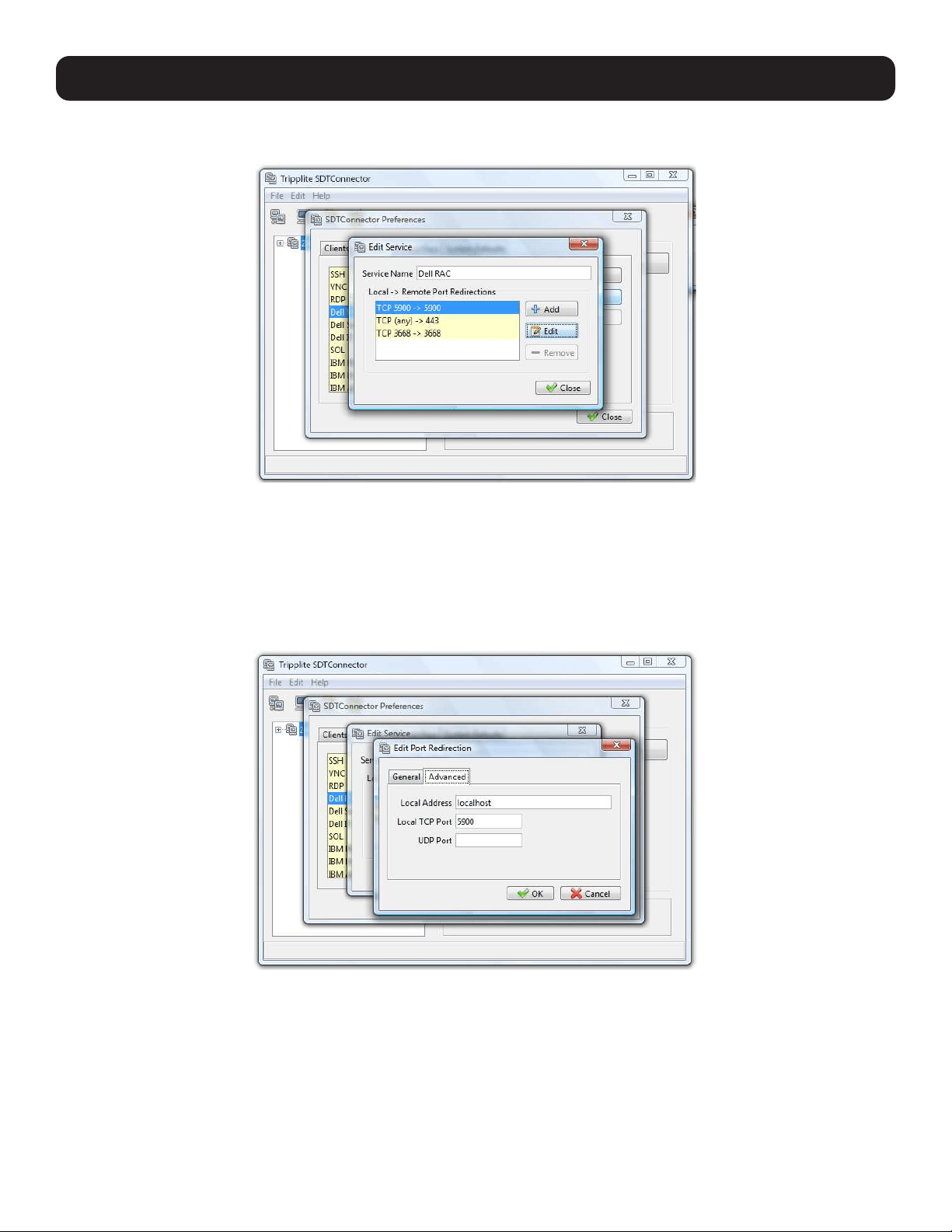
107
6. SSH Tunnels and SDT Connector
The second redirection is the VNC service that the user may choose to later launch from the RAC web console. It is
automatically loads in a Java client served through the web browser, so it does not need a local client associated with it.
• On the Add Service screen, you can click Add as many times as needed to add multiple new port redirections and
associated clients.
You may also specify Advanced port redirection options:
• Enter the local address to bind to when creating the local endpoint of the redirection. It is not usually necessary to change
this from “localhost”.
• Enter a local TCP port to bind to when creating the local endpoint of the redirection. If this is left blank, a random port will be
selected.
Note: SDT Connector can also tunnel UDP services. SDT Connector tunnels the UDP traffic through the TCP SSH redirection, effectively
making it is a tunnel within a tunnel.
Enter the UDP port on which the service is running on the host. This will also be the local UDP port the SDT Connector binds to as the local
endpoint of the tunnel.
For UDP services, you will need to specify a TCP port under the General tab. This will be an arbitrary TCP port that is not in use on the
gateway. An example of this is the SOL Proxy service. It redirects local UDP port 623 to remote UDP port 623 over the arbitrary TCP port
6667.
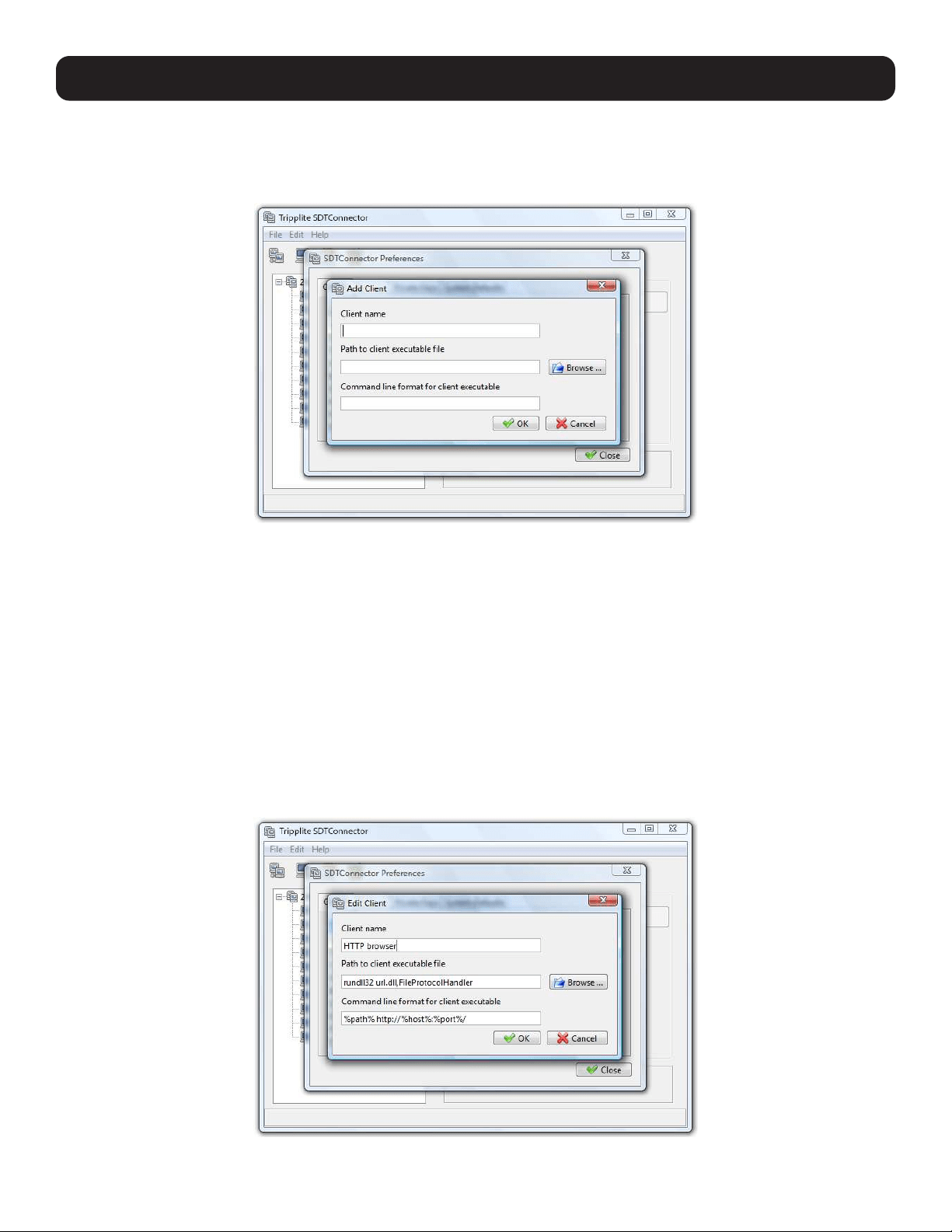
108
6. SSH Tunnels and SDT Connector
6.2.7 Adding a Client Program to Be Started for the New Service
Clients are local applications that may be launched when a related service is clicked. To add to the pool of client programs:
• Select Edit: Preferences and click the Client tab. Click Add.
• Enter a Name for the client. Enter the Path to the executable file for the client (or click Browse to locate the executable).
• Enter a Command Line associated with launching the client application. SDT Connector typically launches a client using
command line arguments to point it at the local endpoint of the redirection. There are three special keywords for specifying
the command line format. When launching the client, SDT Connector substitutes these keywords with the appropriate
values:
%path% is path to the executable file, i.e. the previous field.
%host% is the local address to which the local endpoint of the redirection is bound, i.e. the Local Address field for the
Service redirection Advanced options.
%port% is the local port to which the local endpoint of the redirection is bound, i.e. the Local TCP Port field for the
Service redirection Advanced options. If this port is unspecified (i.e. “Any”), the appropriate randomly selected port will be
substituted.
For example, SDT Connector is preconfigured for Windows installations with a HTTP service client that will connect with
whichever local browser the local Windows user has configured as the default. Otherwise, the default browser used is Firefox:
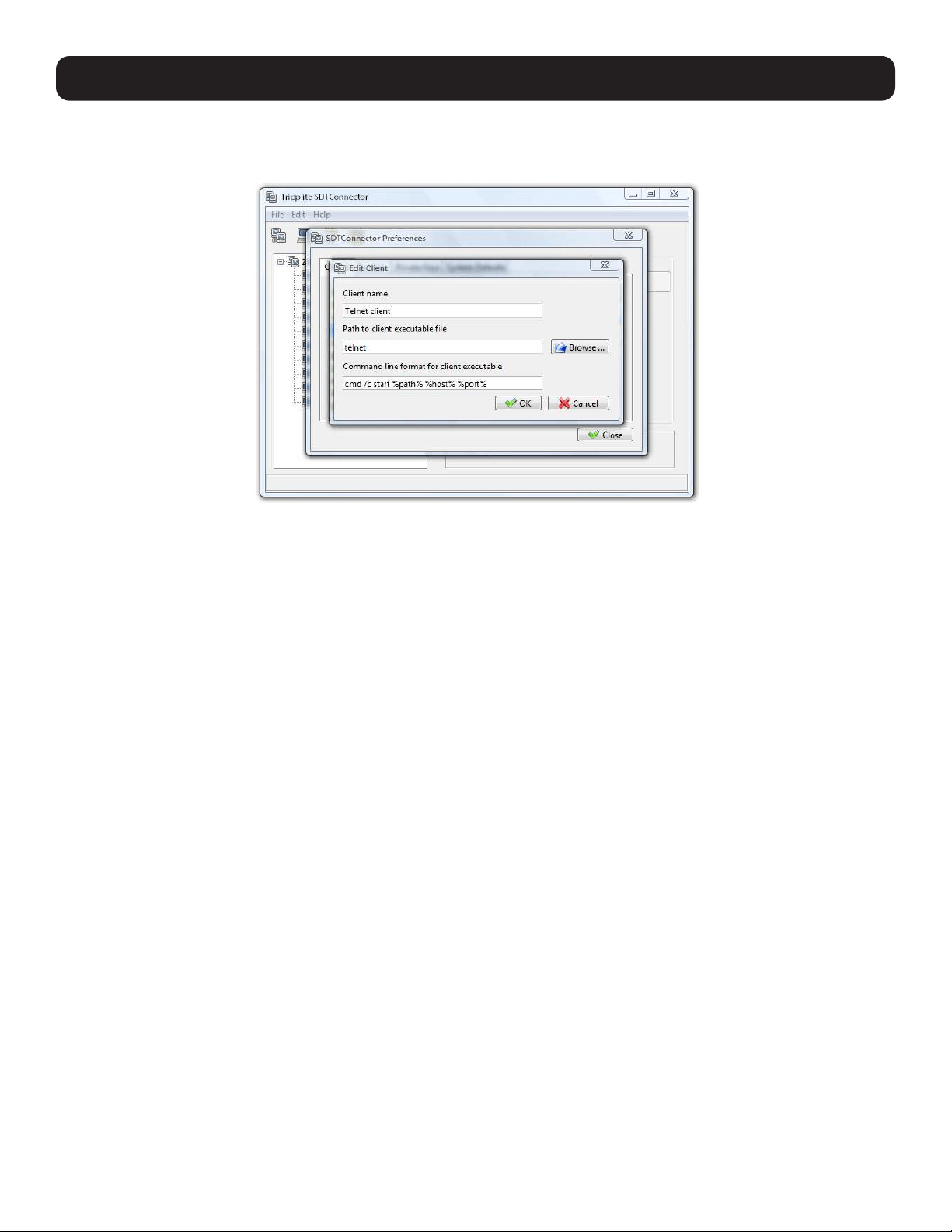
109
Also, some clients are launched in a command line or terminal window. The telnet client is an example of this. As such,
the “Path to client executable file” is telnet and the “Command line format for client executable” is cmd /c start %path%
%host% %port%:
• Click OK.
6.2.8 Dial-In Configuration
If the client PC is dialing in to the Local/Console port on the console server, you will need to set up a dial-in PPP link:
• Configure the console server for dial-in access (refer to 5.2.1 Configuring Dial-In PPP).
• Set up the PPP client software at the remote User PC.
Once you have a dial-in PPP connection established, you can set up the secure SSH tunnel from the remote Client PC to the
console server.
6. SSH Tunnels and SDT Connector
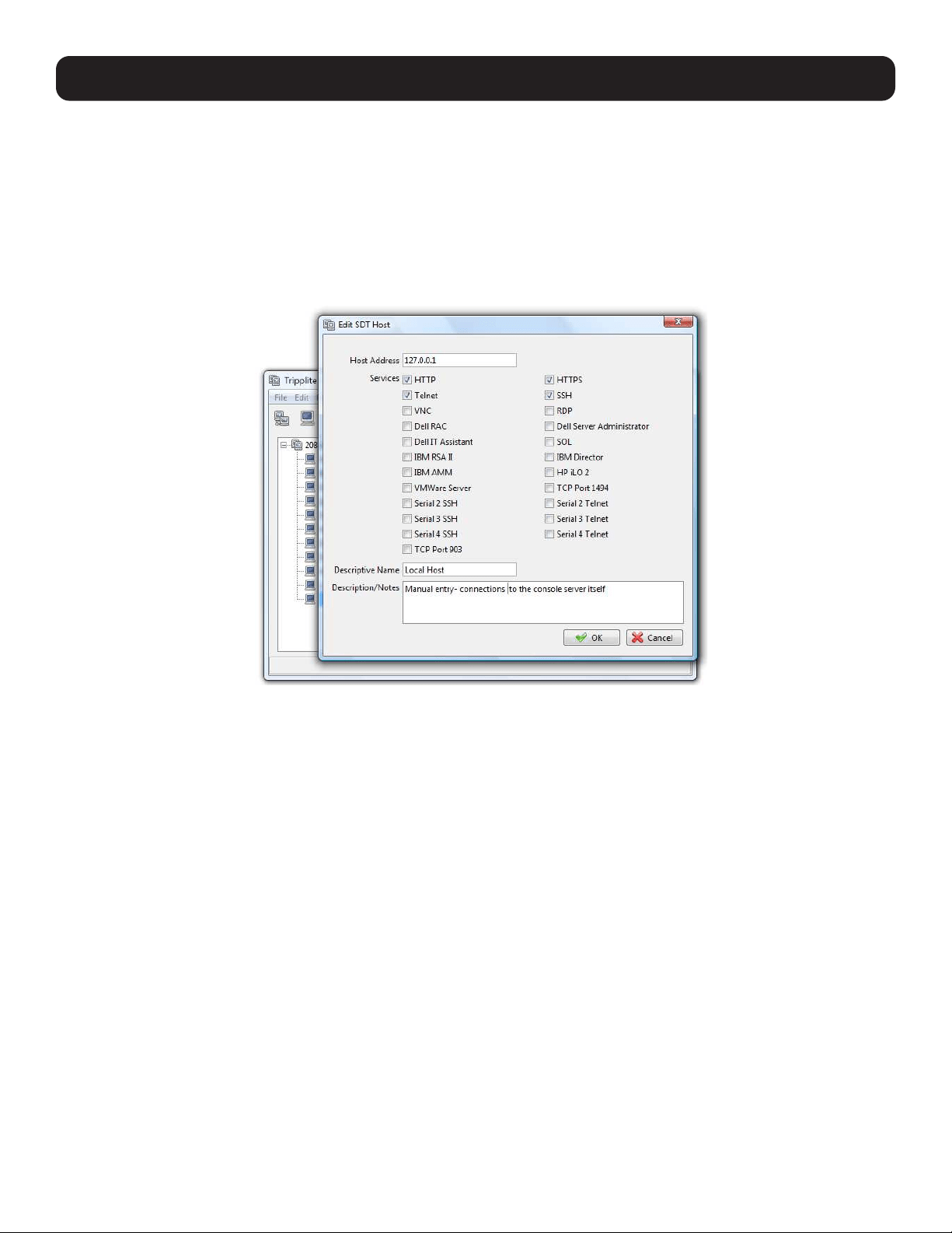
110
6. SSH Tunnels and SDT Connector
6.3 SDT Connector to Management Console
SDT Connector can also be configured for browser access the gateway’s Management Console – and for Telnet or SSH access
to the gateway command line. For these connections to the gateway itself, you must configure SDT Connector to access the
gateway (itself) by setting the Console server up as a host, and then configuring the appropriate services:
• Launch SDT Connector on your PC. Assuming you have already set up the console server as a Gateway in your SDT
Connector client (with username / password, etc.), select this newly added Gateway and click the Host icon to create a
host. Alternately, select File: New Host
• Enter 127.0.0.1 as the Host Address and provide details in Descriptive Name/Notes. Click OK.
• Click the HTTP or HTTPS services icon to access the gateway’s management console, and/or click SSH or Telnet to access
the gateway command line console.
Note: To enable SDT access to the gateway console, you must configure the console server to allow port forwarded network access.
With firmware version 3.3 and later, this can be done using the console server management Console. Simply browse to the console server
and select the Service Access tab on the System: Firewall menu. Ensure SSH Command Shell is enabled on the network interface and
any out of band interfaces.
With earlier firmware:
• Browse to the console server and select Network Hosts from Serial & Network. Click Add Host. In the IP Address/DNS Name field,
enter 127.0.0.1 (this is the console server’s network loopback address) and enter Loopback in Description.
• Remove all entries under Permitted Services, except those that will be used in accessing the management console (80/http or 443/
https) or the command line (22/ssh or 23/telnet). Then scroll to the bottom and click Apply.
• By default, Administrators have gateway access privileges. For Users to access the gateway management console, you will need to
provide those Users the required access privileges. Select Users & Groups from Serial & Network. Click Add User. Enter a Username,
Description and Password/Confirm. Select 127.0.0.1 from Accessible Host(s) and click Apply.
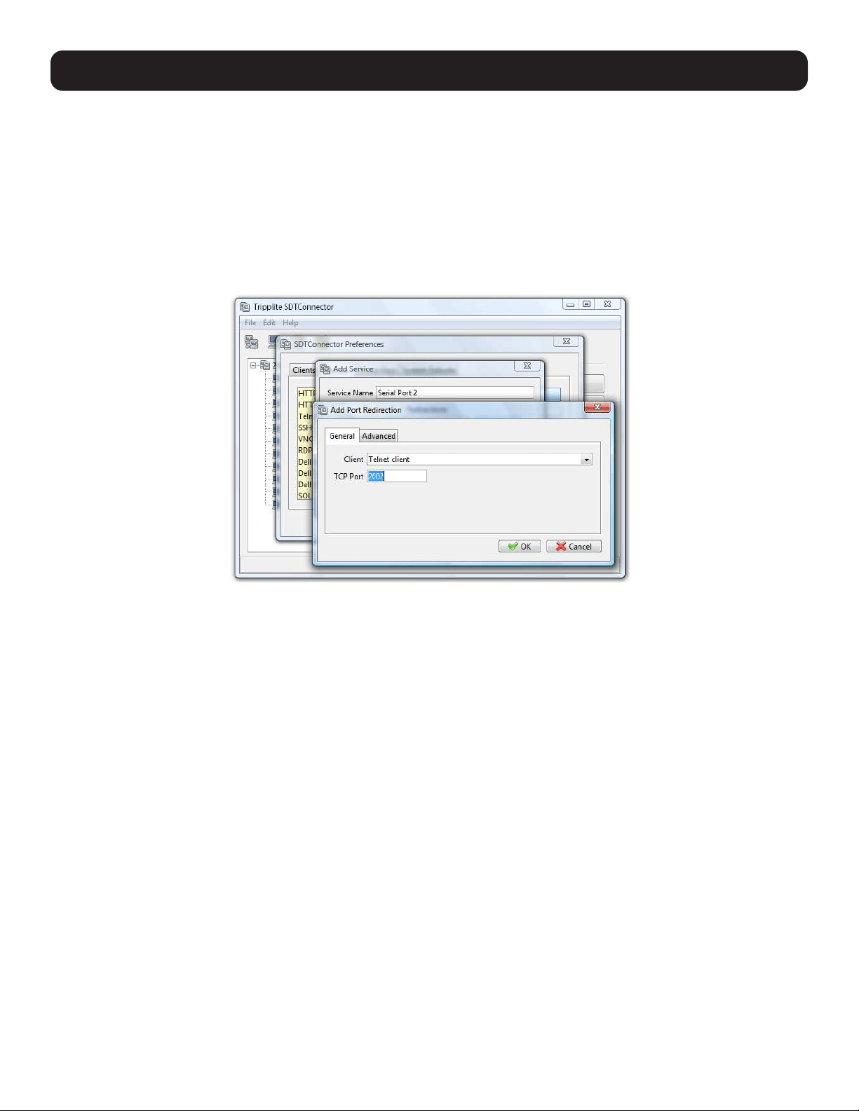
111
6. SSH Tunnels and SDT Connector
6.4 SDT Connector: Telnet or SSH Connect to Serially Attached
Devices
SDT Connector can also be used to access text consoles on devices that are attached to the console server’s serial ports. For
these connections, you must configure the SDT Connector client software with a service that will access the target gateway
serial port, and then set the gateway up as a host:
• Launch SDT Connector on your PC. Select Edit: Preferences and click the Services tab. Click Add.
• Enter “Serial Port 2” in Service Name and click Add.
• Select Telnet client as the Client. Enter 2002 in TCP Port. Click OK, then Close and Close again.
• Assuming you have already set up the target console server as a gateway in your SDT Connector client (with username /
password, etc.), select this gateway and click the Host icon to create a host. Alternately, select File: New Host.
• Enter 127.0.0.1 as the Host Address and select Serial Port 2 for service. In Descriptive Name, enter something along
the lines of Loopback ports, or Local serial ports. Click OK.
• Click the Serial Port 2 icon for Telnet access to the serial console on the device attached to serial port 2 on the gateway.
To enable SDT Connector to access to devices connected to the gateway’s serial ports, you must also configure the console
server itself to allow port forwarded network access to itself, and enable access to the assigned serial port:
• Browse to the console server and select Serial Port from Serial & Network.
• Click Edit next to selected Port # (e.g. Port 2 if the target device is attached to the second serial port). Ensure the port’s
serial configuration is appropriate for the attached device.
• Scroll down to Console Server Setting and select Console Server Mode. Check Telnet (or SSH). Scroll to the bottom
and click Apply.
• Select Network Hosts from Serial & Network and click Add Host.
• In the IP Address/DNS Name field, enter 127.0.0.1 (this is the console server’s network loopback address) and enter
Loopback in Description.
• Remove all entries under Permitted Services, select TCP and enter 200n in Port. This configures the telnet port enabled
in the previous step, so for Port 2 you would enter 2002.
• Click Add, then scroll to the bottom and click Apply.
• By default, Administrators have gateway and serial port access privileges. For Users to access the gateway and serial port,
you will need to provide those Users the required access privileges. Select Users & Groups from Serial & Network. Click
Add User. Enter a Username, Description and Password/Confirm. Select 127.0.0.1 from Accessible Host(s) and select
Port 2 from Accessible Port(s). Click Apply.
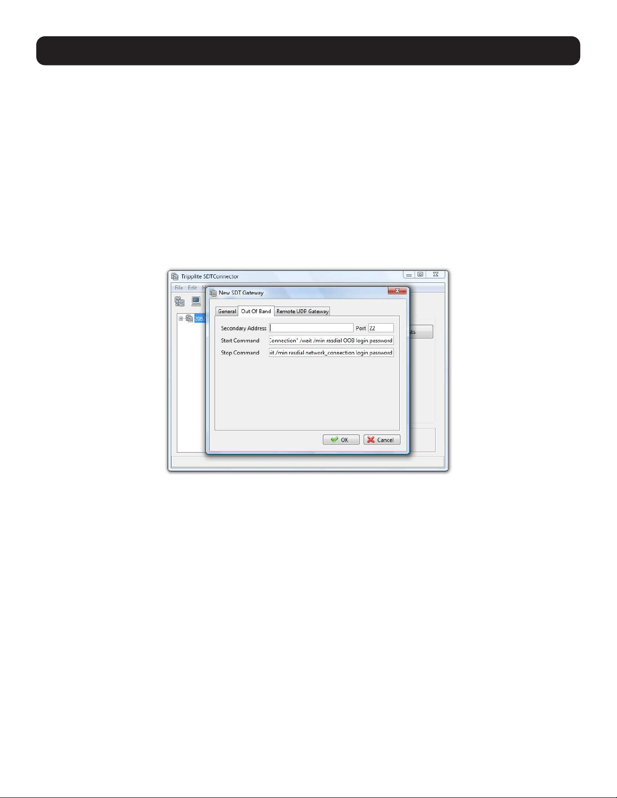
112
6. SSH Tunnels and SDT Connector
6.5 Using SDT Connector for Out-of-Band (OOB) Connection to the
Gateway
SDT Connector can also be set up to connect to the console server (gateway) out-of-band (OOB). OOB access uses an
alternate path for connecting to the gateway to that used for regular data traffic. OOB access is useful when the primary link to
the gateway is unavailable or unreliable.
A gateway’s primary link is typically a broadband Internet connection or Internet connection via LAN or VPN. Secondary out-of-
band connectivity is provided by a dial-up or wireless modem directly attached to the gateway. Out-of-band access enables you
to access the hosts and serial devices on the network, diagnose any connectivity issues, and restore the gateway’s primary
link.
In SDT Connector, OOB access is configured by providing the gateway’s secondary IP address and communicating to the SDT
Connector how to start and stop the OOB connection. Starting an OOB connection may be achieved by initiating a dial-up
connection, or adding an alternate route to the gateway. SDT Connector allows for maximum flexibility is this regard by allowing
you to provide your own scripts or commands for starting and stopping the OOB connection.
To configure SDT Connector for OOB access:
• When adding a new gateway or editing an existing gateway, select the Out Of Band tab.
• Enter the gateway’s secondary OOB IP address (e.g., the accessible IP address used when dialed in directly). You also may
modify the gateway’s SSH port if it is not using the default of 22.
• In Start Command, enter the command or path to a script to start the OOB connection.
o To initiate a pre-configured dial-up connection under Windows, use the following Start Command:
cmd /c start “Starting Out of Band Connection” /wait /min rasdial network_connection login password
where network_connection is the name of the network connection as displayed in Control Panel -> Network Connections,
login is the dial-in username, and password is the dial-in password for the connection.
o To initiate a pre-configured dial-up connection under Linux, use the following Start Command:
pon network_connection
where network_connection is the name of the connection.
• Enter the command or path to a script to stop the OOB connection in Stop Command.
o To stop a pre-configured dial-up connection under Windows, use the following Stop Command:
cmd /c start “Stopping Out of Band Connection” /wait /min rasdial network_connection /disconnect
where network connection is the name of the network connection as displayed in Control Panel -> Network Connections.
o To stop a pre-configured dial-up connection under Linux, use the following Stop Command:
poff network_connection
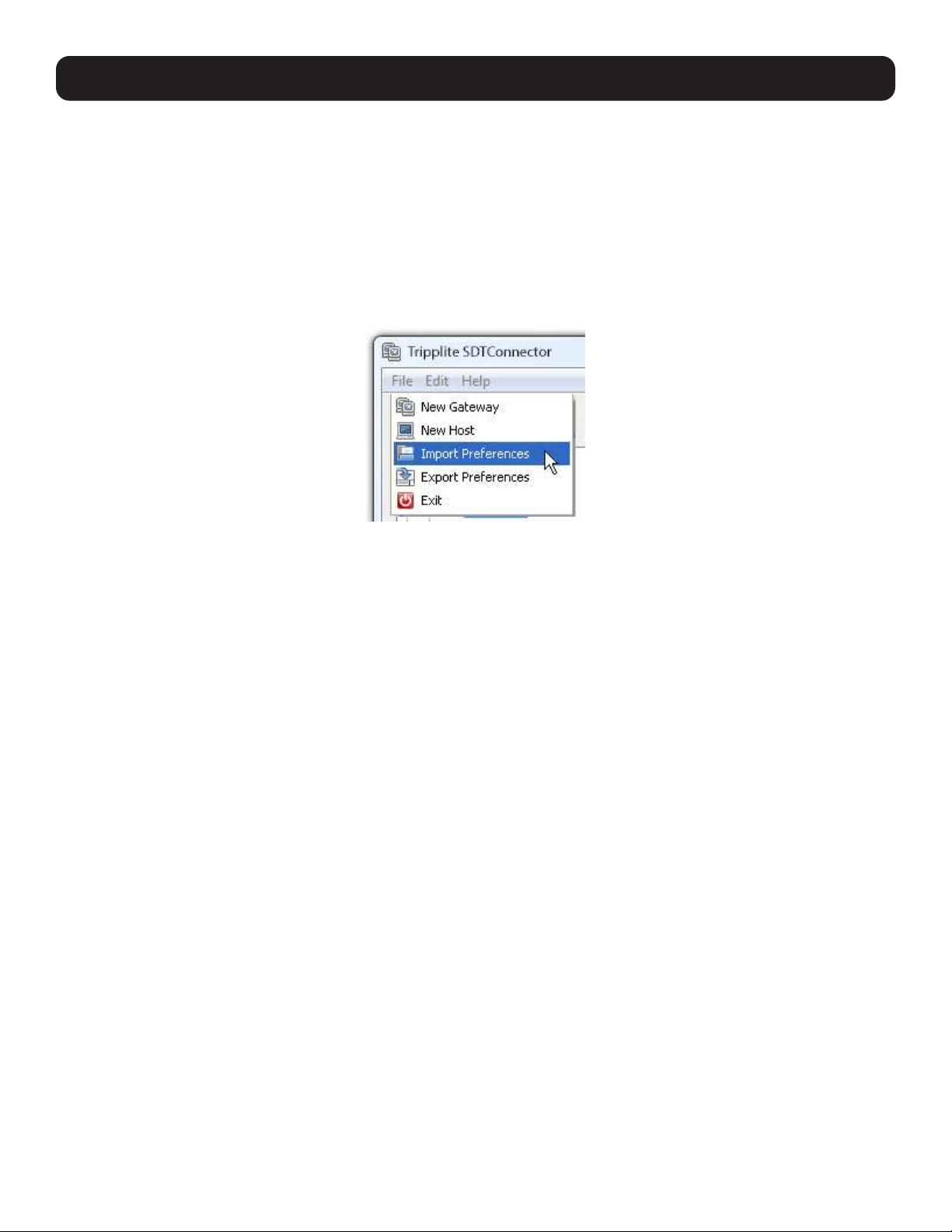
113
To make the OOB connection using SDT Connector:
• Select the gateway and click Out Of Band. The status bar will change color to indicate this gateway is now being accessed
using the OOB link rather than the primary link.
When you connect to a service on a host behind the gateway, or to the console server gateway itself, SDT Connector will
initiate the OOB connection using the provided Start Command. The OOB connection isn’t stopped (using the provided Stop
Command) until Out Of Band under Gateway Actions is clicked off, at which point the status bar will return to its normal color.
6.6 Importing (and Exporting) Preferences
To enable the distribution of pre-configured client configuration files, use the SDT Connector’s Export/Import function:
• To save a configuration .xml file (for backup or importing into other SDT Connector clients), select File: Export Preferences
and select the location to save the configuration file.
• To import a configuration, select File: Import Preferences and select the .xml configuration file to be installed.
6.7 SDT Connector Public Key Authentication
SDT Connector can authenticate against an SSH gateway using your SSH key pair, rather than requiring you to enter your
password. This is known as public key authentication.
To use public key authentication with SDT Connector, first add the public part of your SSH key pair to your SSH gateway:
• Ensure the SSH gateway allows public key authentication. This is typically the default behavior.
• If you do not already have a public/private key pair for your client PC (the one running SDT Connector) generate them using
ssh-keygen, PuTTYgen or a similar tool. You may use RSA or DSA, however, it is important you leave the passphrase field
blank:
- PuTTYgen: http://www.chiark.greenend.org.uk/~sgtatham/putty/download.html
- OpenSSH: http://www.openssh.org/
- OpenSSH (Windows): http://sshwindows.sourceforge.net/download/
• Upload the public part of your SSH key pair (this file is typically named id_rsa.pub or id_dsa.pub) to the SSH gateway.
Otherwise, add to .ssh/authorized keys in your home directory on the SSH gateway.
• Next, add the private part of your SSH key pair (this file is typically named id_rsa or id_dsa) to SDT Connector. Click Edit:
Preferences: Private Keys: Add and locate the private key file. Click OK.
You do not have to add the public part of your SSH key pair, it is calculated using the private key.
SDT Connector will now use public key authentication when connecting through the SSH gateway (console server). You may
have to restart SDT Connector to shut down any existing tunnels that were established using password authentication.
Also, if you have a host behind the console server that you connect to by clicking the SSH button in SDT Connector, you may
also wish to configure access for public key authentication. This configuration is entirely independent of SDT Connector and
the SSH gateway. You must configure the SSH client that SDT Connector launches (e.g., Putty, OpenSSH) and the host’s
SSH server for public key authentication. Essentially, what you are using is SSH over SSH, and the two SSH connections are
entirely separate.
6. SSH Tunnels and SDT Connector
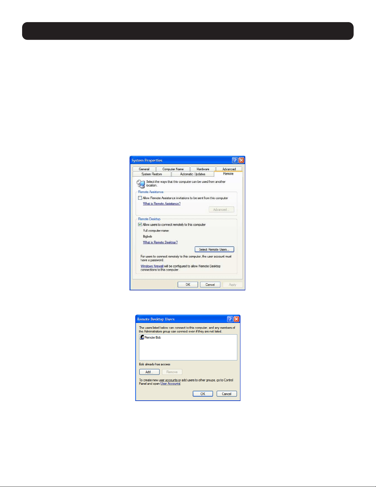
114
6. SSH Tunnels and SDT Connector
6.8 Setting up SDT for Remote Desktop Access
Microsoft’s Remote Desktop Protocol (RDP) enables the system manager to securely access and manages remote Windows
computers – to reconfigure applications and user profiles, upgrade the server’s operating system, reboot the machine, etc. Tripp Lite’s
Secure Tunneling uses SSH tunneling, so this RDP traffic is securely transferred through an authenticated and encrypted tunnel.
SDT with RDP also allows remote users to connect to Windows XP and later computers and to Windows 2000 Terminal
Servers. Doing so allows access to all applications, files, and network resources (with full graphical interface). To set up a
secure remote desktop connection, you must enable Remote Desktop on the target Windows computer that is to be accessed
and then configure the RPD client software on the client PC.
6.8.1 Enable Remote Desktop on the Target Windows Computer to Be Accessed
To enable Remote Desktop on the Windows computer being accessed:
• Open System in the Control Panel and click the Remote tab.
• Check Allow users to connect remotely to this computer.
• Click Select Remote Users.
• To set the user(s) who can remotely access the system with RDP, click Add on the Remote Desktop Users dialog box.
Notes: If you need to set up new users for Remote Desktop access, open User Accounts in the Control Panel and proceed through the steps
to assign the new user’s name, password and account type (Administrator or Limited).
With Windows XP Professional and Vista, you have only one remote desktop session, and it connects directly to the Windows root console.
With Windows Server 2008, you can have multiple sessions (with Server 2003 you have three sessions - the console session and two other
general sessions).
When the remote user connects to the accessed computer on the console session, remote desktop automatically locks that computer so no
other user can access the applications and files. When you return to your computer, you can unlock it by typing CTRL+ALT+DEL.
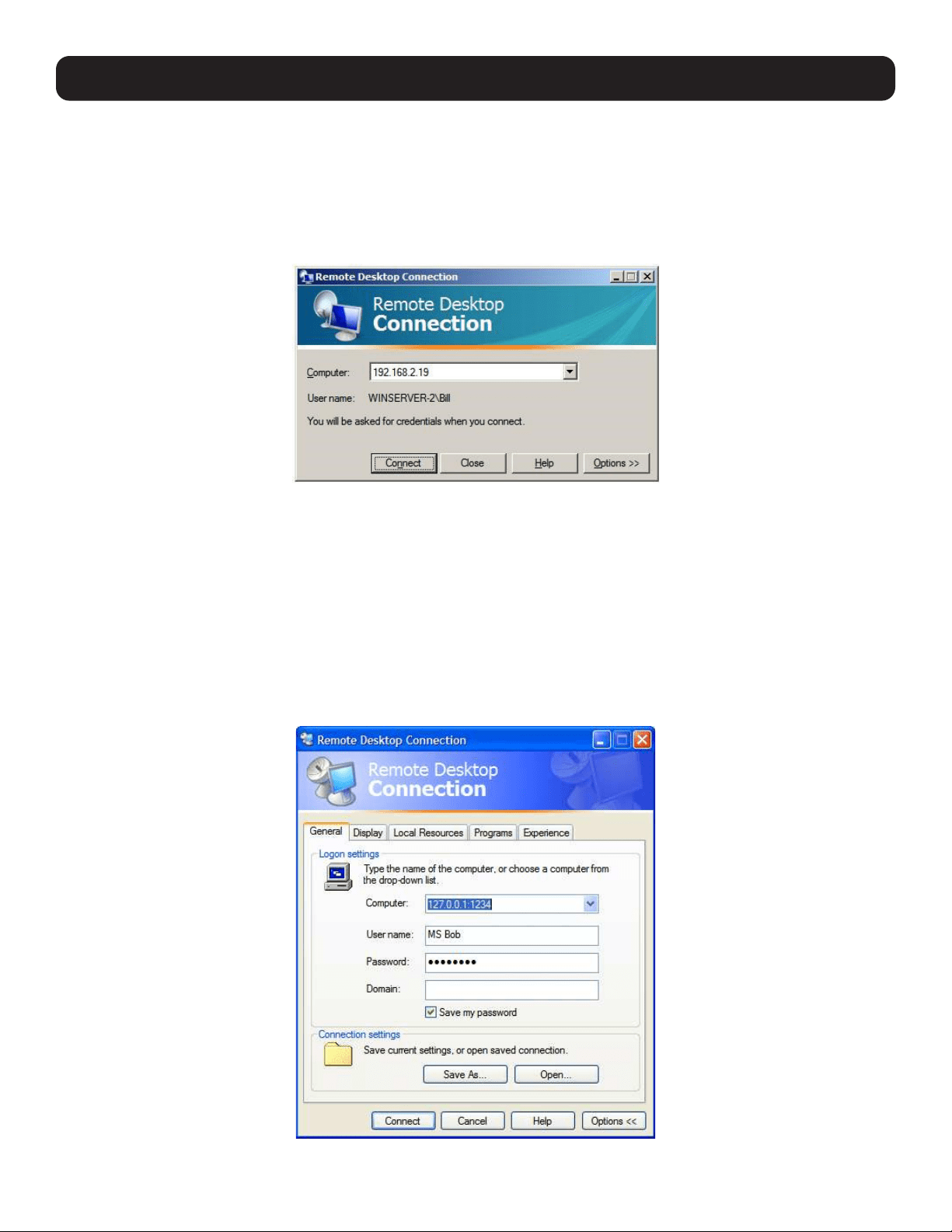
115
6.8.2 Configure the Remote Desktop Connection Client
With the Client PC securely connected to the console server (locally, remotely from the enterprise VPN, or a secure SSH
internet tunnel or dial-in SSH tunnel), you can establish the remote desktop connection from the client. Simply enable the
Remote Desktop Connection on the remote client PC, and then point it to the SDT Secure Tunnel port in the console server:
On a Windows client PC
Click Start. Point to Programs, then to Accessories, then Communications. Click Remote Desktop Connection.
In Computer, enter the appropriate IP Address and Port Number:
• Where there is a direct local or enterprise VPN connection, enter the console server’s IP Address and the Port Number of
the SDT Secure Tunnel for the console server serial port that is attached to the Windows computer to be controlled. For
example, if the Windows computer is connected to serial Port 3 on a console server located at 192.168.0.50, then you
would enter 192.168.0.50:7303.
Where there is an SSH tunnel over a dial-up PPP connection, public internet connection, or private network connection, simply
enter the localhost as the IP address 127.0.0.1. For the port number, enter the source port you created when setting SSH
tunneling /port forwarding (e.g., :1234).
Click Option. In the Display section, specify an appropriate color depth (e.g., for a modem connection it is recommended
you not use over 256 colors). In Local Resources, specify the peripherals on the remote Windows computer that are to be
controlled (printer, serial port, etc.).
Click Connect.
6. SSH Tunnels and SDT Connector
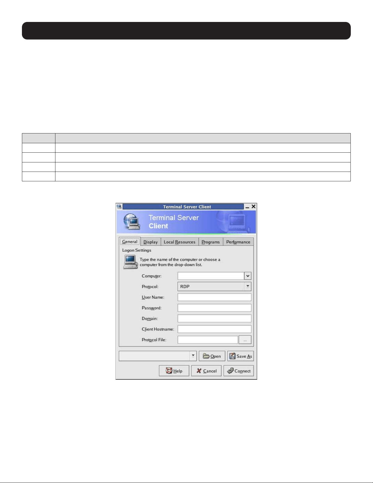
116
6. SSH Tunnels and SDT Connector
Note: The Remote Desktop Connection software is pre-installed with Windows XP and later. For earlier Windows PCs, you will need to
download the RDP client:
Go to the Microsoft Download Center site http://www.microsoft.com/downloads/details.aspx?familyid=80111F21-D48D-426E-96C2-
08AA2BD23A49&displaylang=en and click the Download button.
This software package will install the client portion of Remote Desktop on Windows 95, Windows 98 and 98 Second Edition, Windows Me,
Windows NT 4.0 and Windows 2000. When run, this software allows these older Windows platforms to remotely connect to a computer
running the current Windows version.
On a Linux or UNIX client PC:
Launch the open source rdesktop client:
rdesktop -u windows-user-id -p windows-password -g 1200x950 ms-windows-terminal-server-host-name
Option Description
-a Color depth: 8, 16, 24
-r Device redirection. i.e. Redirect sound on remote machine to local device i.e. -0 -r sound (MS/Windows 2003)
-g Geometry: widthxheight or 70% screen percentage.
-p Use -p - to receive password prompt.
You can use GUI front end tools like the GNOME Terminal Services Client tsclient to configure and launch the rdesktop client
(using tsclient also enables you to store multiple configurations of rdesktop for connection to many servers).
Note: The rdesktop client is supplied with Red Hat 9.0:
rpm -ivh rdesktop-1.2.0-1.i386.rpm
For Red Hat 8.0 or other distributions of Linux; download source, untar, configure, make, make then install.
rdesktop currently runs on most UNIX based platforms with the X Window System and can be downloaded from /
On a Macintosh client:
Download Microsoft’s free Remote Desktop Connection client for Mac OS X
http://www.microsoft.com/mac/otherproducts/otherproducts.aspx?pid=remotedesktopclient
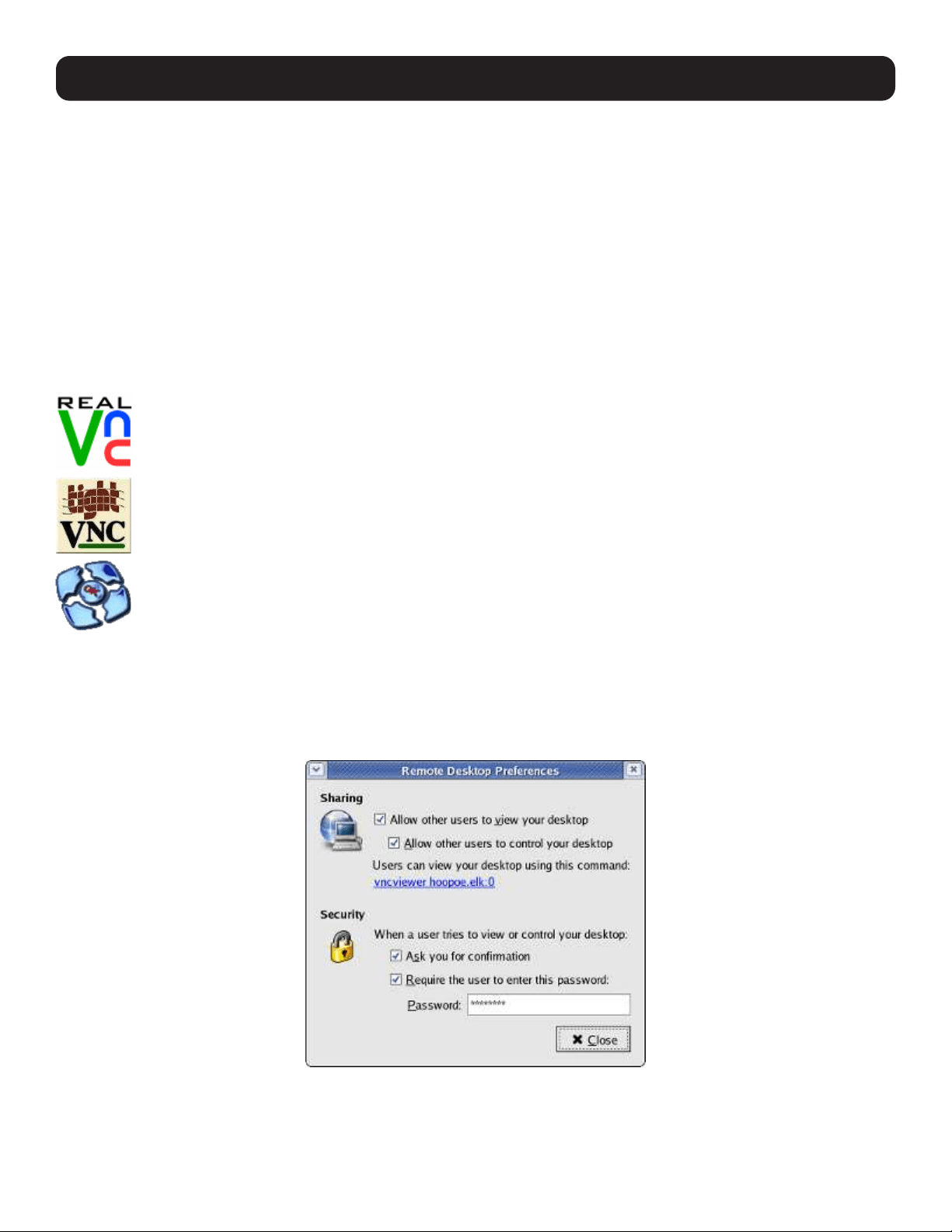
117
6.9 SDT SSH Tunnel for VNC
Alternately, with SDT and Virtual Network Computing (VNC), users and administrators can securely access and control
Windows, Linux, Macintosh, Solaris and UNIX computers. There is a wide range of free popular VNC software options available
(UltraVNC, RealVNC, TightVNC). To set up a secure VNC connection, you must install and configure the VNC Server software
on the computer to be accessed, then install and configure the VNC Viewer software on the Viewer PC.
6.9.1 Install and Configure the VNC Server on the Computer to be Accessed
Virtual Network Computing (VNC) software enables users to remotely access computers running Linux, Macintosh, Solaris,
UNIX, all versions of Windows and most other operating systems.
For Microsoft Windows servers (and clients):
Windows does not include VNC software, so you will need to download, install and activate a third party VNC Server software
package:
RealVNC: http://www.realvnc.com is fully cross-platform, so a desktop running on a Linux machine may be
displayed on a Windows PC, on a Solaris machine, or on any number of other architectures. There is a Windows
server allowing you to view the desktop of a remote Windows machine on any of these platforms using exactly
the same viewer. RealVNC was founded by members of the AT&T team who originally developed VNC.
TightVNC: http://www.tightvnc.com is an enhanced version of VNC. It has added features such as file transfer,
performance improvements, and read-only password support. They have just recently included a video drive
much like UltraVNC. TightVNC is still free, cross-platform (Windows UNIX and Linux) and compatible with the
standard (Real) VNC.
UltraVNC: http://ultravnc.com is easy to use, fast and free VNC software that has pioneered and perfected
features that the other flavors have consistently refused or been very slow to implement for cross platform
and minimalist reasons. UltraVNC runs under Windows operating systems (95, 98, Me, NT4, 2000, XP, 2003)
Download UltraVNC from Sourceforge’s UltraVNC file list.
For Linux servers (and clients):
Most Linux distributions now include VNC Servers and Viewers and generally can be launched from the (Gnome/KDE etc) front
end (e.g. with Red Hat Enterprise Linux 4, there is VNC Server software and a choice of Viewer client software). To launch:
• Select the Remote Desktop entry in the Main Menu: Preferences menu.
• Check the Allow other users… checkbox to allow remote users to view and control your desktop.
6. SSH Tunnels and SDT Connector
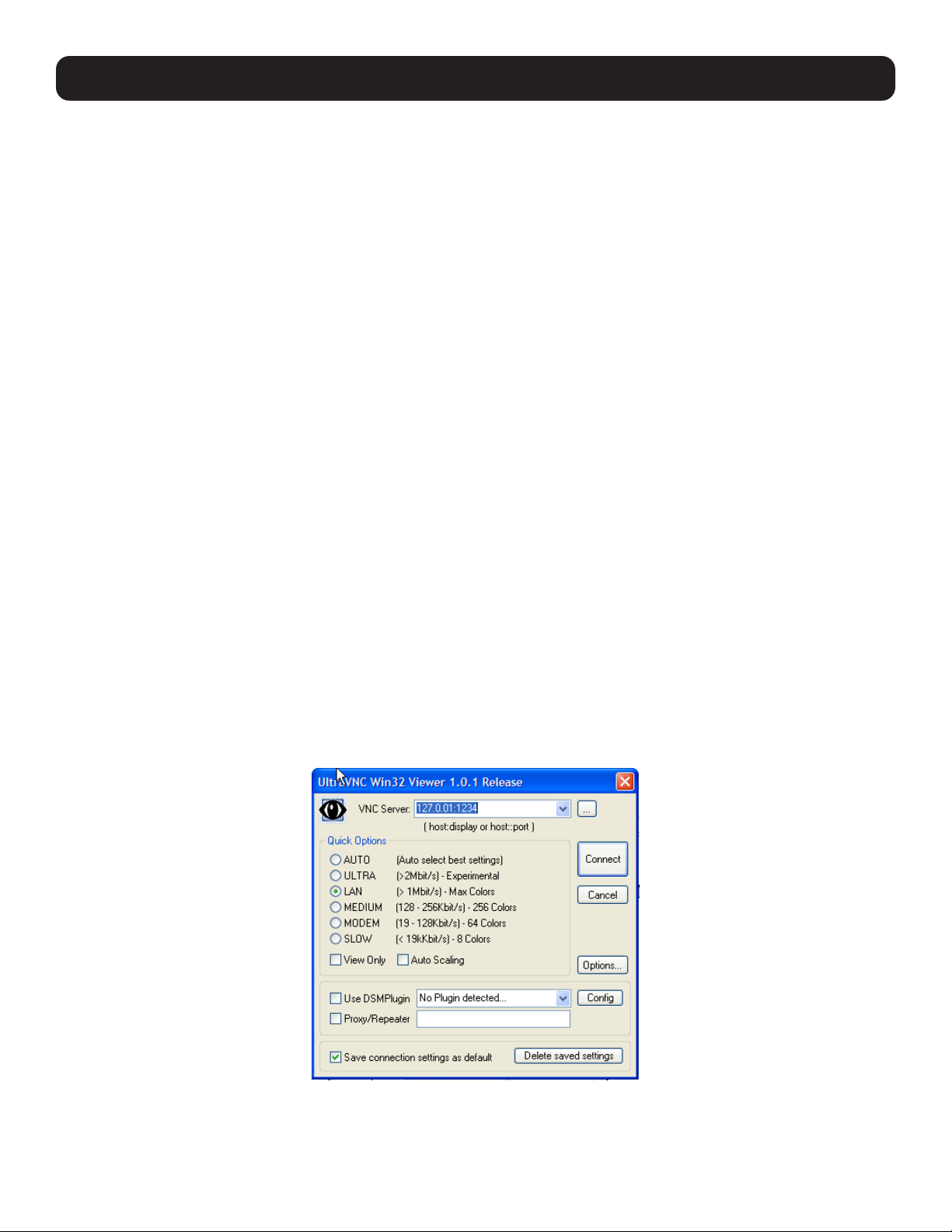
118
6. SSH Tunnels and SDT Connector
• To set up a persistent VNC server on Red Hat Enterprise Linux 4:
o Set a password using vncpasswd.
o Edit /etc/sysconfig/vncservers.
o Enable the service with chkconfig vncserver on.
o Start the service with service vncserver start.
o Edit /home/username/.vnc/xstartup if you want a more advanced session than just twm and an xterm.
For Macintosh servers (and clients):
OSXvnc http://www.redstonesoftware.com/vnc.html is a robust, full-featured VNC server for Mac OS X that allows any VNC
client to remotely view and/or control the Mac OS X machine. OSXvnc is supported by Redstone Software.
Most other operating systems (Solaris, HPUX, PalmOS, etc.) either come with VNC bundled, or have third party VNC software
that you can download.
6.9.2 Install, Configure and Connect the VNC Viewer
VNC is truly platform-independent. A VNC Viewer on any operating system can connect to a VNC Server on any other operating
system. There are Viewers (and Servers) from a wide selection of sources (e.g.,UltraVNC TightVNC or RealVNC) for most
operating systems. There are also a wealth of Java viewers available so any desktop can be viewed with a Java-capable
browser (http://en.wikipedia.org/wiki/VNC lists many of the VNC Viewers sources).
• Install the VNC Viewer software and set it up for the appropriate speed connection.
Note: To make VNC faster, when you set up the Viewer:
• Set encoding to ZRLE (if you have a fast enough CPU)
• Decrease color level (e.g., 64 bit)
• Disable the background transmission on the Server or use a plain wallpaper
(refer to http://doc.uvnc.com for detailed configuration instructions).
• To establish the VNC connection, first configure the VNC Viewer by entering the VNC Server IP address.
When the Viewer PC is connected to the console server through an SSH tunnel (over the public Internet, dial-in connection, or
private network connection), enter localhost (or 127.0.0.1) as the IP VNC Server IP address. Use the source port you entered
when setting SSH tunneling /port forwarding (in section 6.2.6 Manually Adding New Services to the New Hosts)
e.g., :1234.
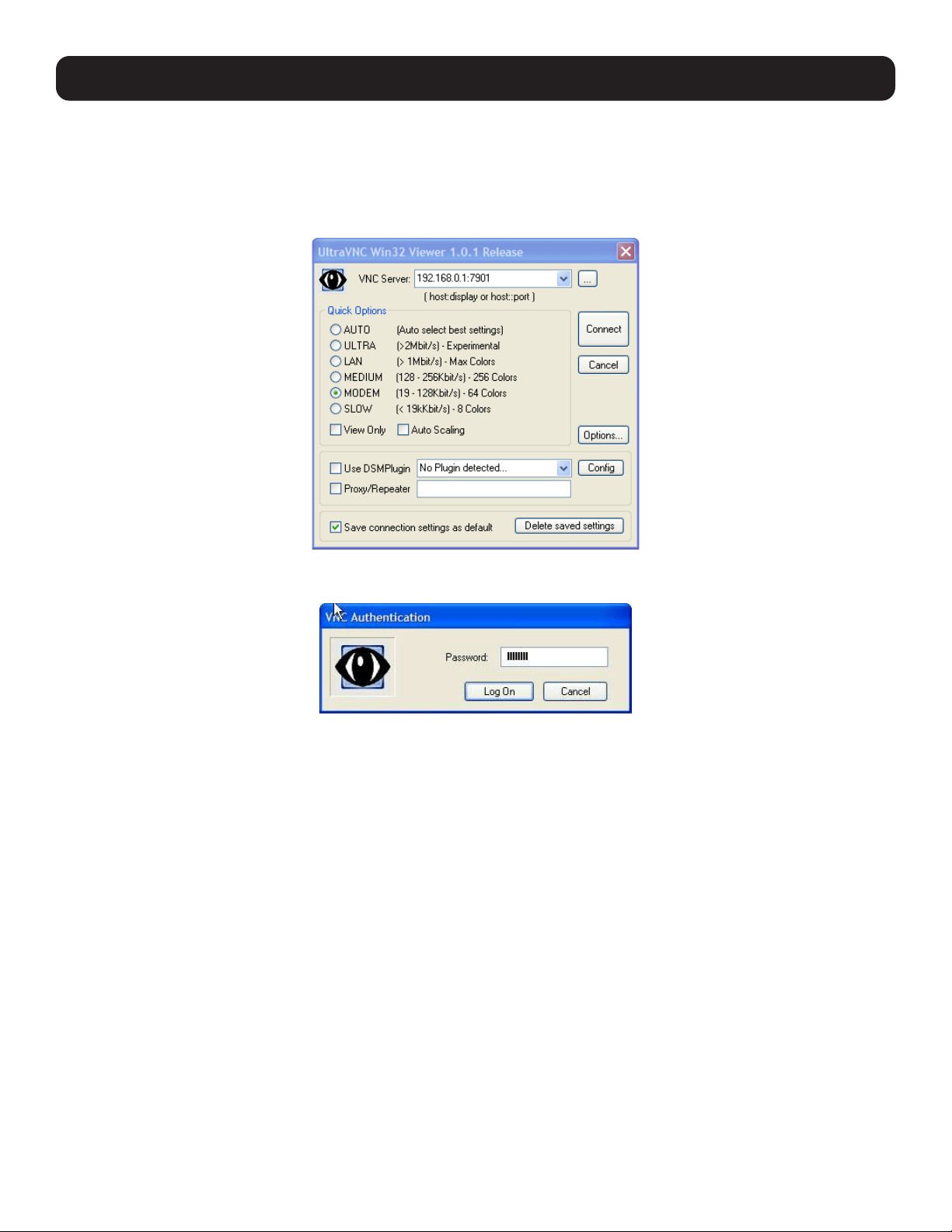
119
When the Viewer PC is directly connected to the console server (i.e. locally or remotely via VPN or dial-in connection) and the
VNC Host computer is serially connected to the console server, enter the IP address of the console server unit with the TCP
port that the SDT tunnel will use. The TCP port will be 7900 plus the physical serial port number. For example, with TCP ports
7901 to 7948, all traffic directed to port 79xx on the console server is tunneled through to port 5900 on the PPP connection
on serial Port xx (e.g., for a Windows Viewer PC using UltraVNC connecting to a VNC Server, which is attached to Port 1 on a
console server located 192.168.0.1).
• You can then establish the VNC connection by simply activating the VNC Viewer software on the Viewer PC and entering the
password.
Note: For general background reading on Remote Desktop and VNC access, we recommend the following:
• The Microsoft Remote Desktop How-To http://www.microsoft.com/windowsxp/using/mobility/getstarted/remoteintro.mspx
• The Illustrated Network Remote Desktop help page http://theillustratednetwork.mvps.org/RemoteDesktop/
RemoteDesktopSetupandTroubleshooting.html
• What is Remote Desktop in Windows XP and Windows Server 2003? by Daniel Petri http://www.petri.co.il/what’s_remote_desktop.htm
• Frequently Asked Questions about Remote Desktop http://www.microsoft.com/windowsxp/using/mobility/rdfaq.mspx
• Secure remote access of a home network using SSH, Remote Desktop and VNC for the home user http://theillustratednetwork.mvps.
org/RemoteDesktop/SSH-RDP-VNC/RemoteDesktopVNCandSSH.html
• Taking your desktop virtual with VNC, Red Hat magazine / and /
• Wikipedia general background on VNC http://en.wikipedia.org/wiki/VNC
6.10 Using SDT to IP Connect to Hosts that are Serially Attached to
the Gateway
Network (IP) protocols like RDP, VNC and HTTP can also be used for connecting to the host’s serially connected devices
through their COM port to the console server. To do this:
• Establish a PPP connection between the host and the gateway.
• Set up Secure Tunneling - Ports on the console server.
• Configure SDT Connector to use the appropriate network protocol to access IP consoles on the host devices that are
attached to the Console server serial ports.
6. SSH Tunnels and SDT Connector
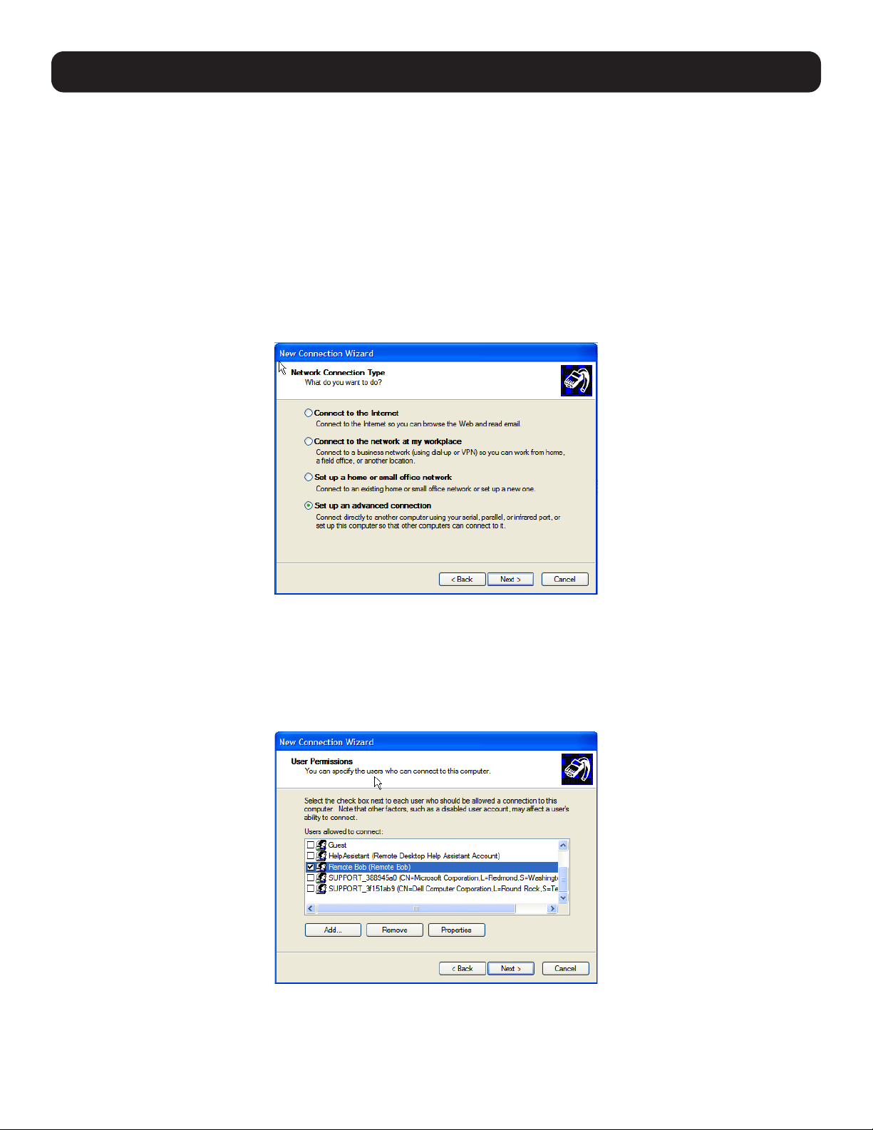
120
6. SSH Tunnels and SDT Connector
6.10.1 Establish a PPP Connection between the Host COM Port and Console Server
(This step is only necessary for serially connected computers)
Physically connect the COM port on the host computer to the serial port on the console server.
For non-Windows (Linux, UNIX, Solaris, etc.) computers, establish a PPP connection over the serial port. The online
tutorial (http://www.yolinux.com/TUTORIALS/LinuxTutorialPPP.html) presents a selection of methods for establishing a PPP
connection for Linux.
For Windows XP and 2003 computers, follow the steps below to set up an advanced network connection between the
Windows computer and through its COM port to the console server. Both Windows 2003 and Windows XP Professional allow
you to create a simple dial-in service which can be used for the Remote Desktop/VNC/HTTP/X connection to the console
server:
• Open Network Connections in Control Panel and click the New Connection Wizard.
• Select Set up an advanced connection and click Next.
• On the Advanced Connection Options screen, select Accept Incoming Connections and click Next.
• Select the Connection Device (i.e. the serial COM port on the Windows computer that is connected to the console server).
By default, select COM1. The COM port on the Windows computer should be configured to its maximum baud rate. Click
Next.
• On the Incoming VPN Connection Options screen, select Do not allow virtual private connections. Click Next.
• Specify which users will be allowed to use this connection. These should be the same users who were given remote desktop
access privileges in the earlier step. Click Next.
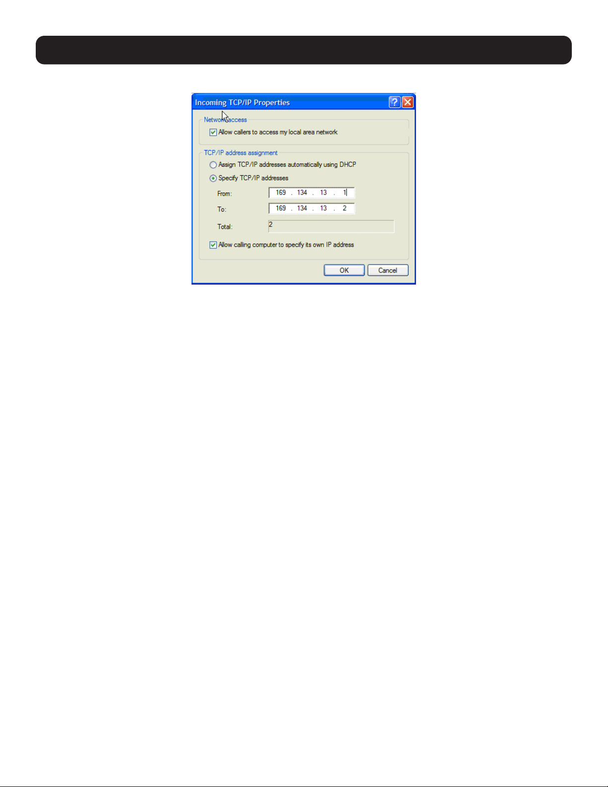
121
6. SSH Tunnels and SDT Connector
• On the Network Connection screen, select TCP/IP, then click Properties.
• Select Specify TCP/IP addresses on the Incoming TCP/IP Properties screen, then select TCP/IP. Assign a From: and a
To: TCP/IP address. Click Next.
Note: You can choose any TCP/IP addresses as long as they are not used anywhere else on your network. The From: address will be
assigned to the Windows XP/2003 computer and the To: address will be used by the console server. For simplicity, use the following IP
address:
From: 169.134.13.1
To: 169.134.13.2
Alternately, you can set the advanced connection and access on the Windows computer to use the console server defaults:
• Specify 10.233.111.254 as the From: address.
• Select Allow calling computer to specify its own address.
Additionally, you can use the console server default username and password when you set up the new Remote Desktop User. In doing so,
the user is granted permission to use the advanced connection to access the Windows computer:
• The console server default username is portXX, where XX is the serial port number on the console server.
• The default Password is portXX.
To use the defaults for a RDP connection to the serial port 2 on the console server, you will need to set up a Windows user named port02.
• When the PPP connection has been set up, a network icon will appear in the Windows task bar.
Note: The above notes describe setting up an incoming connection for Windows XP. The steps are similar for later versions with some slight
differences:
• You need to check the box for Always allow directly connected devices.
• Also, the option for to Set up an advanced connection is not available in Windows 2003 if RRAS is configured. If RRAS has been
configured, it is a simply task to enable the null modem connection for the dial-in configuration.
For earlier versions of Windows, follow the steps in the For Windows XP and 2003 computers section. To get to the Make
New Connection button:
• For Windows 2000, click Start and select Settings. At the Dial-Up Networking Folder, click Network and Dial-up
Connections, then click Make New Connection. You may need to first set up connection over the COM port using
Connect directly to another computer before proceeding to Set up an advanced connection.
• For Windows 98, double-click My Computer on the Desktop, then open Dial-Up Networking and double-click.
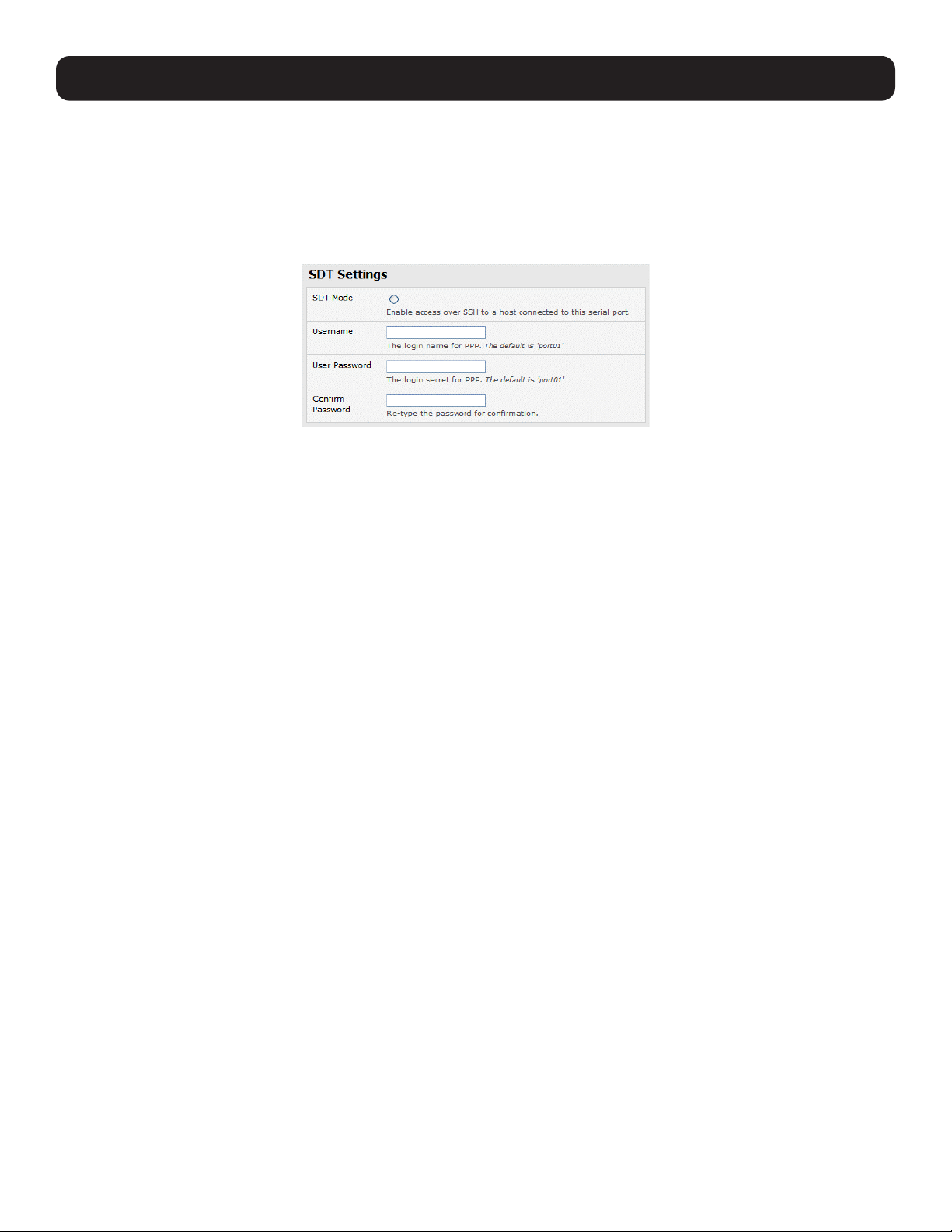
122
6. SSH Tunnels and SDT Connector
6.10.2 Set Up SDT Serial Ports on Console Server
To set up RDP (and VNC) forwarding on the console server serial port that is connected to the Windows computer’s COM port:
• Select the Serial & Network: Serial Port menu option and click Edit (for the particular Serial Port that is connected to the
Windows computer COM port).
• On the SDT Settings menu, select SDT Mode (which will enable port forwarding and SSH tunneling) and enter a Username
and User Password.
Notes:
• Enabling SDT will override all other configuration protocols on that port.
• If you leave the Username and Password fields blank, they default to portXX and portXX, where XX is the serial port number. For
example, the default username and password for Secure RDP over Port 2 is port02.
• Ensure the console server Common Settings (Baud Rate, Flow Control) are the same as were set up on the Windows
computer COM port and click Apply.
• RDP and VNC forwarding over serial ports is enabled by port. You can add users with access to these ports (or reconfigure
User profiles) by selecting Serial & Network: User & Groups menu tag. Refer to 4.1 Configure Serial Ports for more
information.
6.10.3 Set Up SDT Connector to SSH Port Forward over Console Server Serial Port
In the SDT Connector software running on your remote computer, specify the gateway IP address of your console server and a
username/password for a user you have set up on the console server that has access to the desired port.
Next, you need to add a new SDT Host. In the host address, put portxx where xx = the port you are connecting to. For
example, for port 3, you would have a Host Address of: port03, then select the RDP Service check box.
6.11 SSH Tunneling Using Other SSH Clients (e.g. PuTTY)
It is recommend you use the SDT Connector client software supplied with the console server. However, there is also a wide
selection of commercial and free SSH client programs that can provide the secure SSH connections to the console servers
and secure tunnels to connected devices:
• PuTTY is a complete (though not the most user-friendly) freeware implementation of SSH for Win32 and UNIX platforms.
• SSHTerm is a useful open source SSH communications package.
• SSH Tectia is the leading end-to-end commercial communications security solution for enterprise.
• Reflection for Secure IT (formerly F-Secure SSH) is another good commercial SSH-based security solution.
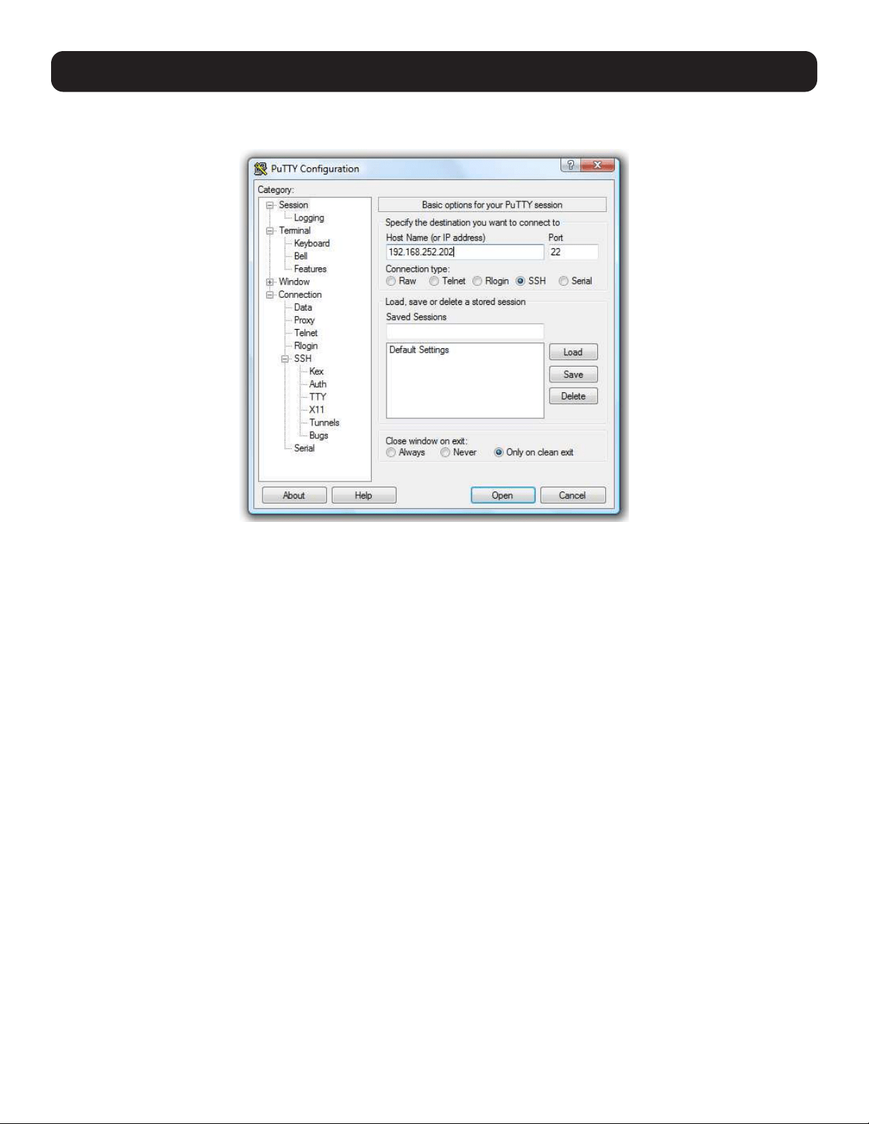
123
The steps below show the establishment of an SSH tunneled connection to a network-connected device using the PuTTY client
software.
In the Session menu, enter the console server’s IP address in the Host Name or IP address field.
• For dial-in connections, this IP address will be the Local address you assigned to the console server when you set it up as
the Dial-In PPP Server.
• For Internet (or local/VPN connections) connections, this will be the public IP address of the console server.
Select the SSH Protocol. The port will be set as 22.
Go to the SSH: Tunnels menu. In Add new forwarded port, enter any frequently unused port number for the source port
(e.g., 54321).
Set the Destination: IP details.
• If your destination device is network-connected to the console server using RDP, set the destination as <Managed Device
IP address/DNS Name>:3389. If when setting up the Managed Device as Network Host on the console server, you
specified its IP address to be 192.168.253.1 (or its DNS Name was accounts.myco.intranet.com), then specify the
destination as 192.168.523.1:3389 (or accounts.myco.intranet.com:3389 ). Only devices that have been configured
as networked hosts can be accessed using SSH tunneling (except by the “root” user who can tunnel to any IP address the
console server can route to).
6. SSH Tunnels and SDT Connector
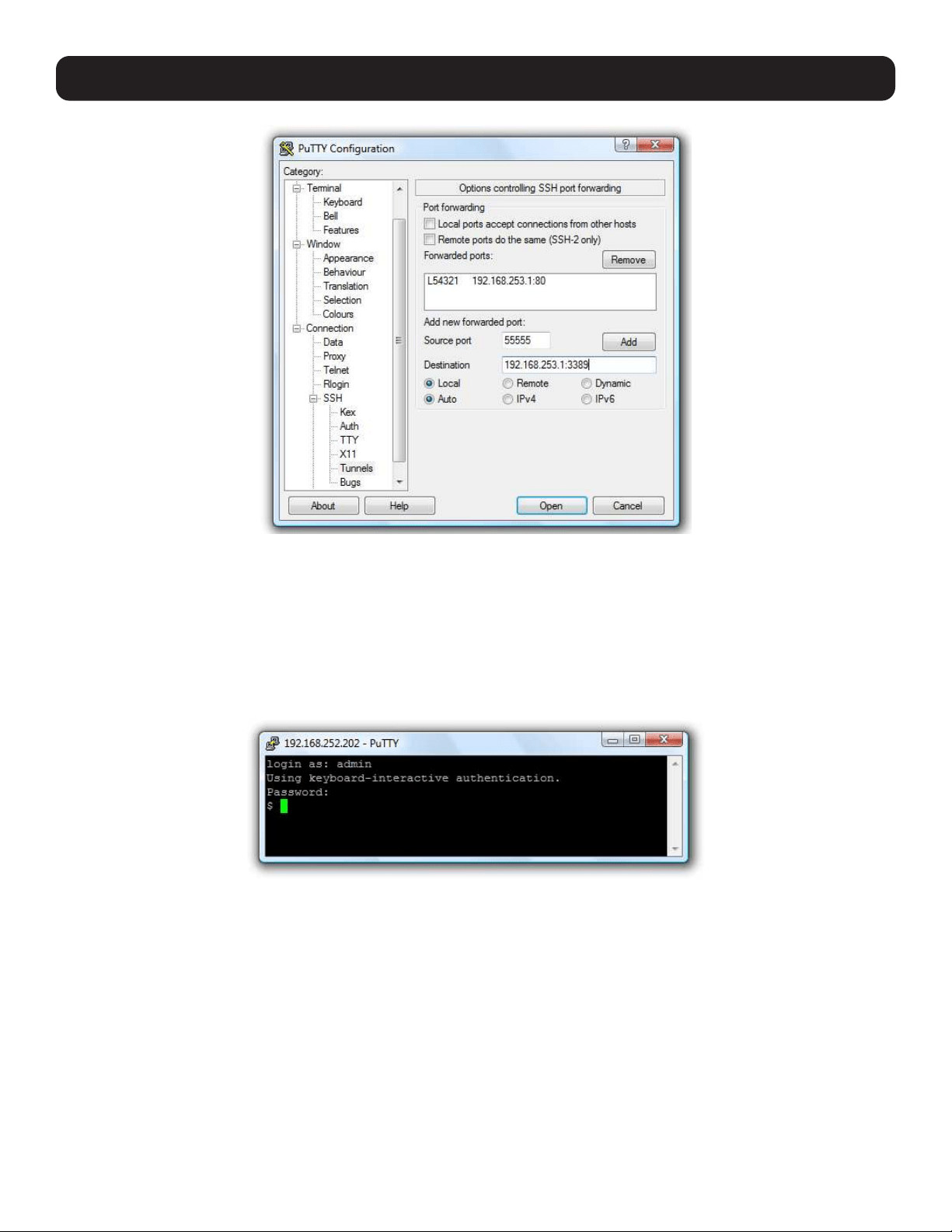
124
6. SSH Tunnels and SDT Connector
• If your destination computer is serially connected to the console server, set the destination as <port label>:3389. If the
label you specified on the console server’s serial port is win2k3, then specify the remote host as win2k3:3389. Alternately,
you can set the destination as portXX:3389, where XX is the SDT enabled serial port number. For example, if port 4 on the
console server is used to carry the RDP traffic, then specify port04:3389.
Note: http://www.jfitz.com/tips/putty_config.html provides useful examples on configuring PuTTY for SSH tunneling.
Select Local and click the Add button.
Click Open to SSH-connect the client PC to the console server. You will be prompted to enter the Username/Password for the
console server user.
• If you are connecting as a User in the “users” group, you can only SSH tunnel to hosts and serial ports where you have
specific access permissions.
• If you are connecting as an Administrator (in the “admin” group), you can connect to any configured host or serial ports
(which has SDT enabled).
To set up the secure SSH tunnel for a HTTP browser connection to the managed device, specify port 80 (rather than port
3389 as was used for RDP) in the destination IP address.
To set up the secure SSH tunnel from the client (Viewer) PC to the console server for VNC, follow the steps above. When
configuring the VNC port redirection, specify port 5900 in the destination IP address.

125
6. SSH Tunnels and SDT Connector
6.12 VNC Security
VNC access generally allows access to your whole computer, so maintaining strong security is important. VNC uses a random
challenge-response system to provide the basic authentication that allows you to connect to a VNC server. This is reasonably
secure and the password is not sent over the network.
Once connected, all subsequent VNC traffic is unencrypted and a malicious user could snoop your VNC session. VNC scanning
programs are also available, which scan a subnet that searches for PCs listening on VNC ports.
Tunneling VNC over a SSH connection ensures all traffic is strongly encrypted. When using this method, no VNC port is ever
open to the internet, so no one scanning for open VNC ports will be able to find your computers. When tunneling VNC over a
SSH connection, the only port which you are opening on your console server is SDT port 22.
Sometimes it may be prudent to tunnel VNC through SSH, even when the viewer PC and the console server are both on the
same local network.
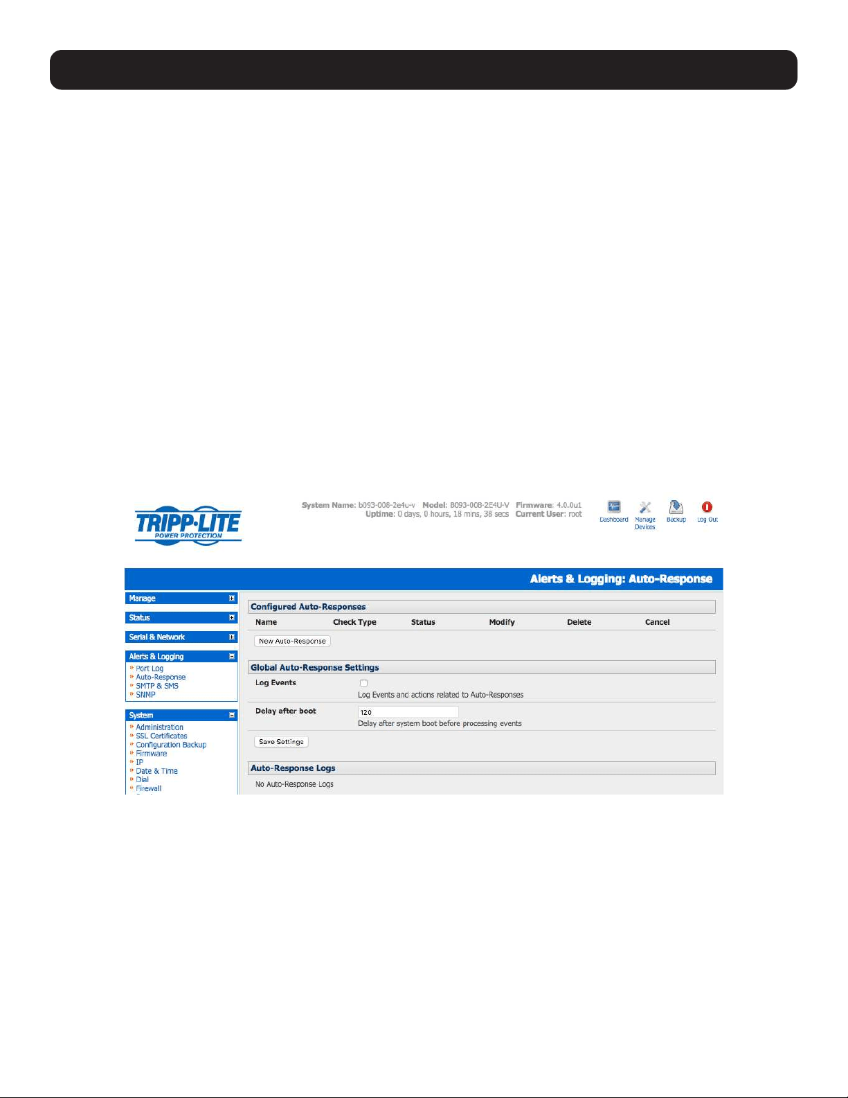
126
7. Alerts, Auto-Response and Logging
This chapter describes the automated response, alert generation and logging features of the console server.
The Auto-Response facility extends on the basic Alert facility available in earlier (pre-V3.5) firmware revisions. With auto-
response, the console server monitors selected serial ports, logins, the power status and environmental monitors and probes
for check condition triggers. The console server will then initiate a sequence of actions in response to these triggers.
All console server models can also maintain log records of all access and communications with the console server and the
attached serial devices. A log of all system activity is maintained as well as history of the status of any attached environmental
monitors.
Some models can also log access and communications with network-attached hosts and maintain a history of the UPS and
PDU power status.
• If port logs are to be maintained on a remote server, then the access path to this location needs to be configured. To do so,
activate and set the desired levels of logging for each serial and/or network port (refer to section7.6 Logging) and/or section
8. Power, Environment and Digital I/O UPS.
7.1 Configure Auto-Response
With the Auto-Response feature, a sequence of trigger actions is initiated in the event of a specified trigger condition (check
condition). Subsequent resolve actions can also be performed when the trigger condition has been resolved.
To configure, first set the general parameters that will be applied to all auto-responses:
• Check Log Events on Alerts & Logging: Auto-Response to enable logging all auto-response activities.
• Check Delay After Boot to set any general delay to be applied after console server system boot before processing events.
To configure a new auto-response:
• Select New Auto-Response in the Configured Auto-Response field. You will be presented with a new Auto-Response
Settings menu.
• Enter a unique Name for the new auto-response.
• Specify the Reset Timeout for the time in seconds after resolution to delay before this Auto-Response can be triggered
again.
• Check Repeat Trigger Actions to continue to repeat trigger action sequences until the check is resolved.
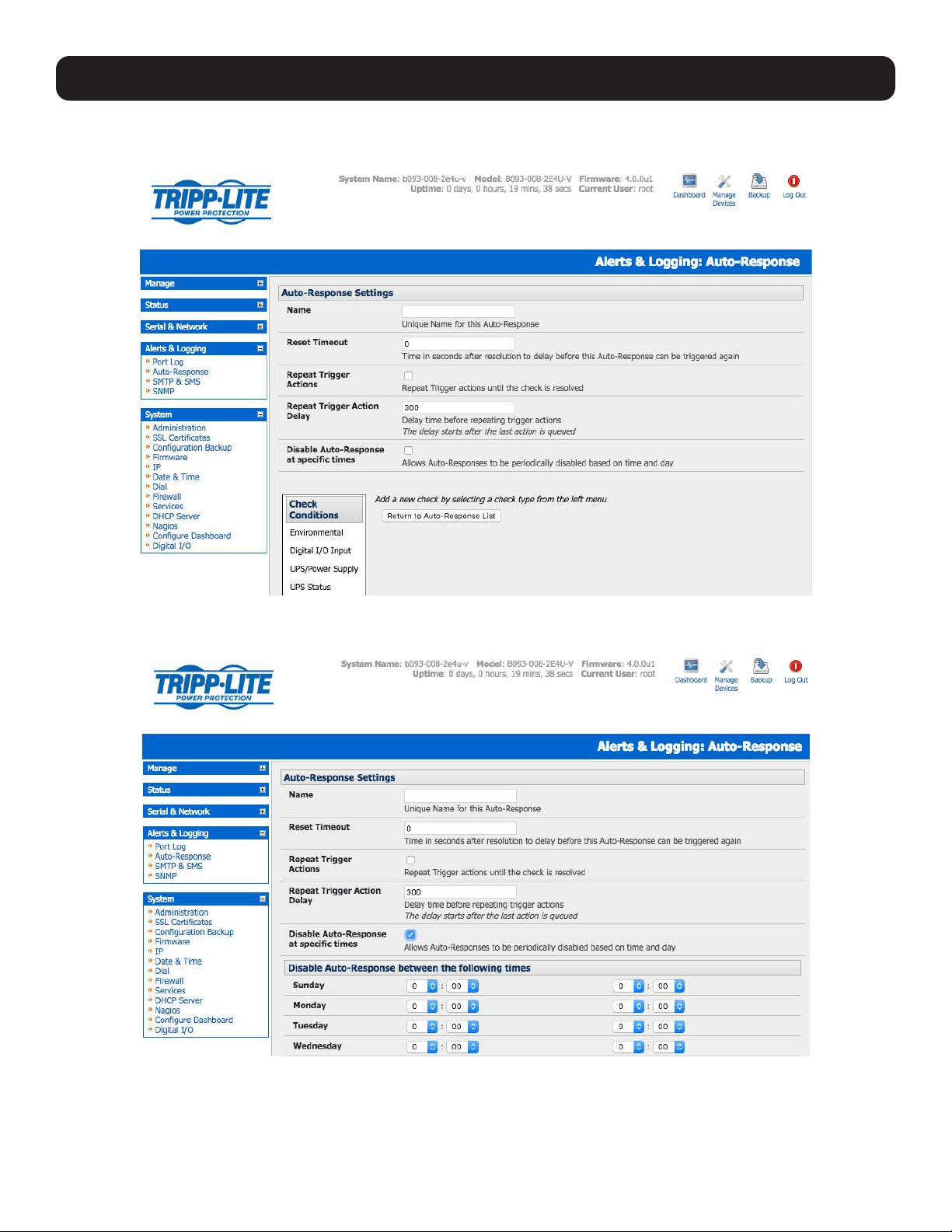
127
7. Alerts, Auto-Response and Logging
• Enter any required delay time before repeating trigger actions in Repeat Trigger Action Delay. This delay starts after the
last action is queued.
• Check Disable Auto-Response at specific times. You will be able to periodically disable auto-responses between specified
times of day.
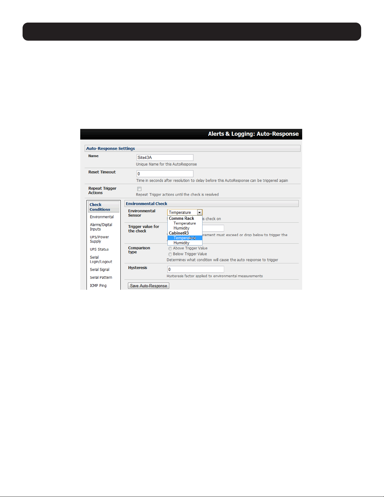
128
7. Alerts, Auto-Response and Logging
7.2 Check Conditions
To configure the condition that will trigger the auto-response:
• Click on the Check Condition type (e.g. Environmental, UPS Status or ICMP ping) to be configured as the trigger for this
new auto-response in the Auto-Response Settings menu.
7.2.1 Environmental
To configure humidity or temperature levels as the trigger event:
• Click on Environmental as the Check Condition.
• In the Environmental Check menu, select the specific Environmental Sensor to be checked for the trigger.
• Specify the Trigger value (in °C / °F for Temp and % for Humidity) that the check measurement must exceed or drop below
to trigger the auto-response.
• Select Comparison type as being Above Trigger Value or Below Trigger Value to trigger.
• Specify any Hysteresis factor that is to be applied to environmental measurements (e.g., if an Auto-Response was set up
with a trigger event of a temp reading above 49°C with a Hysteresis of 4, then the trigger condition would not be seen as
having been resolved until the temp reading was below 45°C) .
• Check Save Auto-Response.
Note: Before configuring environmental checks as the trigger in auto-response, you will need first to configure the temperature and/or
humidity sensors on your attached EMD.
7.2.2 Alarms and Digital Inputs
To set the status of any attached smoke or water sensors or digital inputs as the trigger event:
• Click on Alarms / Digital Inputs as the Check Condition.
• In the Alarms / Digital Inputs Check menu, select the specific Alarm/Digital IO Pin that will trigger the Auto-Response.
• Select Trigger on Change to trigger when alarm signal changes, or select to trigger when the alarm signal state changes to
either a Trigger Value of Open (0) or Closed (1).
• Check Save Auto-Response.
Note: Before configuring Alarms / Digital Inputs checks in Auto-Response, you first must configure the sensor/DIO that is to be attached to
your EMD.
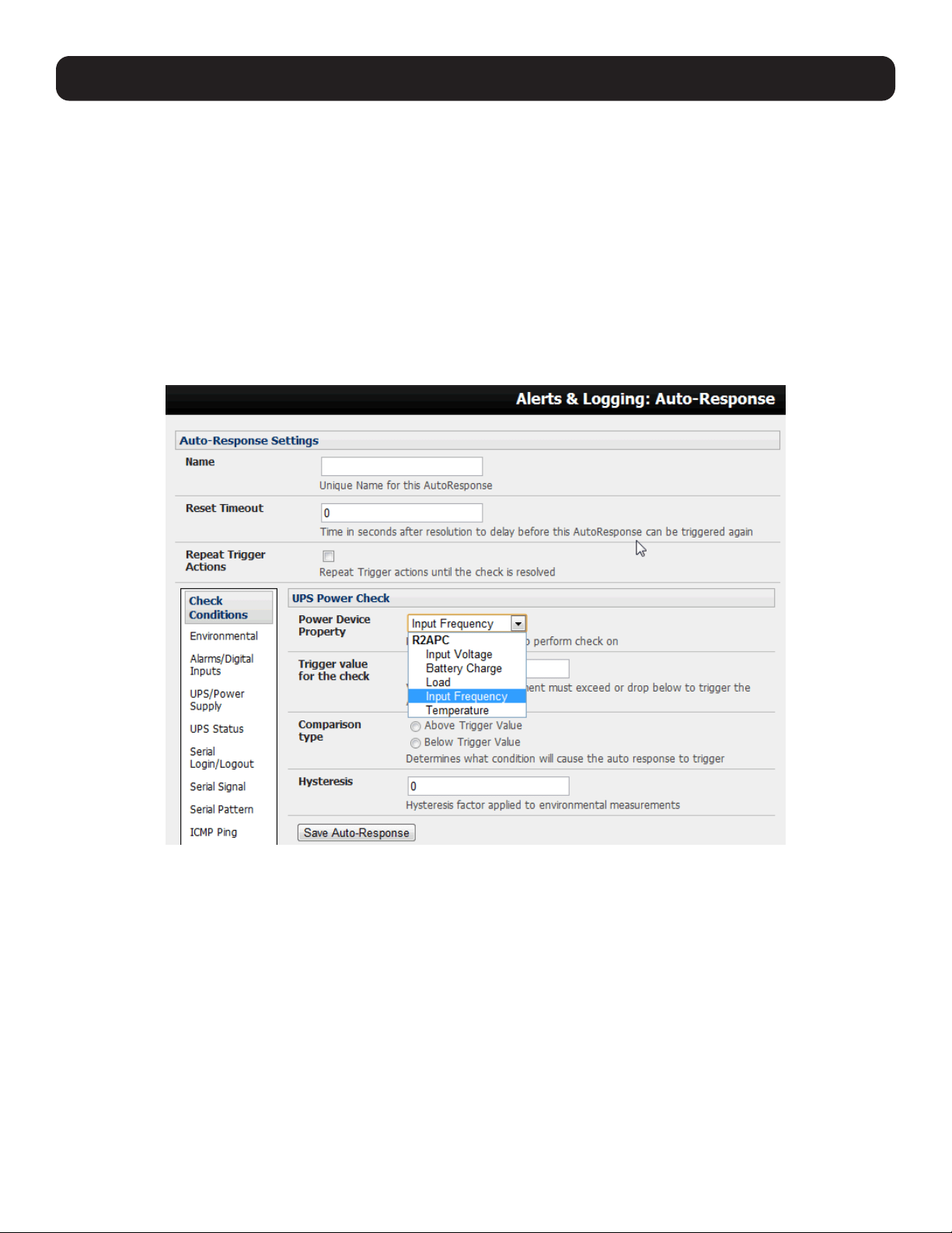
129
7. Alerts, Auto-Response and Logging
7.2.3 UPS/Power Supply
To use the properties of any attached UPS as the trigger event:
• Click on UPS / Power Supply as the Check Condition.
• Select UPS Power Device Property (Input Voltage, Battery Charge %, Load %, Input Frequency Hz or Temperature in °C)
that will checked for the trigger.
• Specify the Trigger value that the check measurement must exceed or drop below in order to trigger the auto-response.
• Select Comparison type as being Above Trigger Value or Below Trigger Value to trigger.
• Specify any Hysteresis factor that is to be applied to environmental measurements (e.g. if an auto-response was set up
with a trigger event of a battery charge below 20% with a hysteresis of 5, then the trigger condition would not be seen as
having been resolved until the battery charge was above 25%).
• Check Save Auto-Response.
Note: Before configuring UPS checks in auto-response, you first must configure the attached UPS.
7.2.4 UPS Status
To use the alert state of any attached UPS as the auto-response trigger event:
• Click on UPS Status as the Check Condition.
• Select the reported UPS State to trigger the auto-response (either On Battery or Low Battery). The auto-response will
resolve when the UPS state returns to the “Online” state.
• Select which connected UPS Device to monitor and check Save Auto-Response.
Note: Before configuring UPS state checks in auto-response, you first must configure the attached UPS.
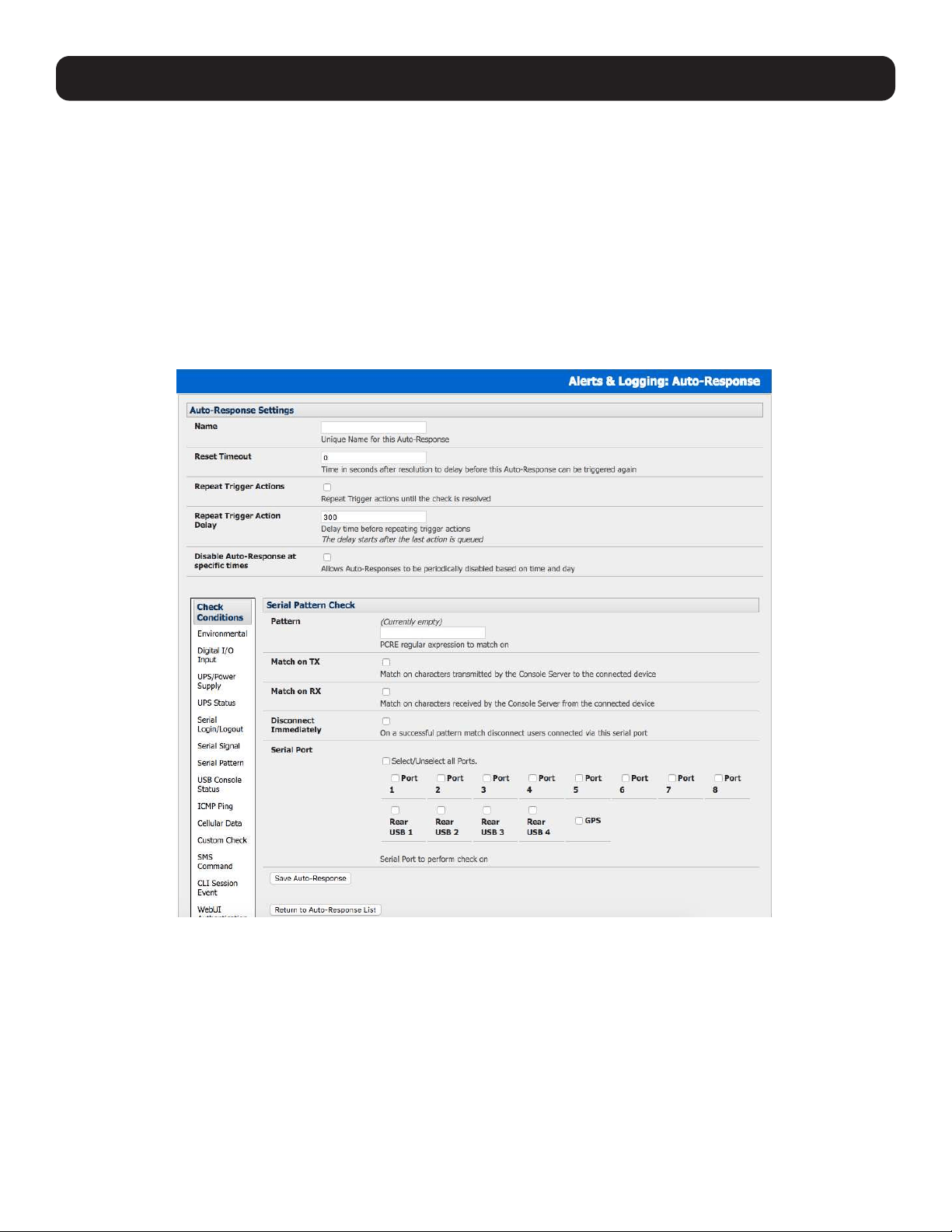
130
7. Alerts, Auto-Response and Logging
7.2.5 Serial Login, Signal or Pattern
To monitor serial ports and check for login/logout or pattern matches for auto-response triggers events:
• Click on Serial Login/Logout as the Check Condition. In the Serial Login/Logout Check menu, select Trigger on Login
(to trigger when any user logs into the serial port) or Trigger on Logout. Specify the Serial Port to perform a check on.
• Click on Serial Signal as the Check Condition. In the Serial Signal Check menu, select the Signal (CTS, DCD, DSR) to
trigger on the Trigger condition (either on serial signal change, or check level). Specify the Serial Port to perform a check
on.
• Click on Serial Pattern as the Check Condition. In the Serial Pattern Check menu, select the PCRE and the serial line
(TX or RX) and Serial Port to pattern check on.
Note: With serial pattern checks, you can assign to “Disconnect Immediately” all users from the serial being monitored in the event of a
successful pattern match.
• Check Save Auto-Response.
Note: Before configuring serial port checks in auto-response, you first must configure the serial port in console server mode. Most serial port
checks are not resolvable, so resolve actions will not be run.
7.2.6 USB Console Status
Note: USB port labels in the Web interface match the USB port labels printed on a console server, with two exceptions. Some console
servers include discrete pairs of USB ports, which do not have printed labels. In this case, the Web interface denotes them as either Upper
or Lower. That is, the Web interface lists them by their physical relationship to each other. Also, some console servers ship with an array
of four USB ports. A limited number of these console servers have labels A – D printed by these ports, even though the Web interface will
denote them as USB ports 1 – 4.
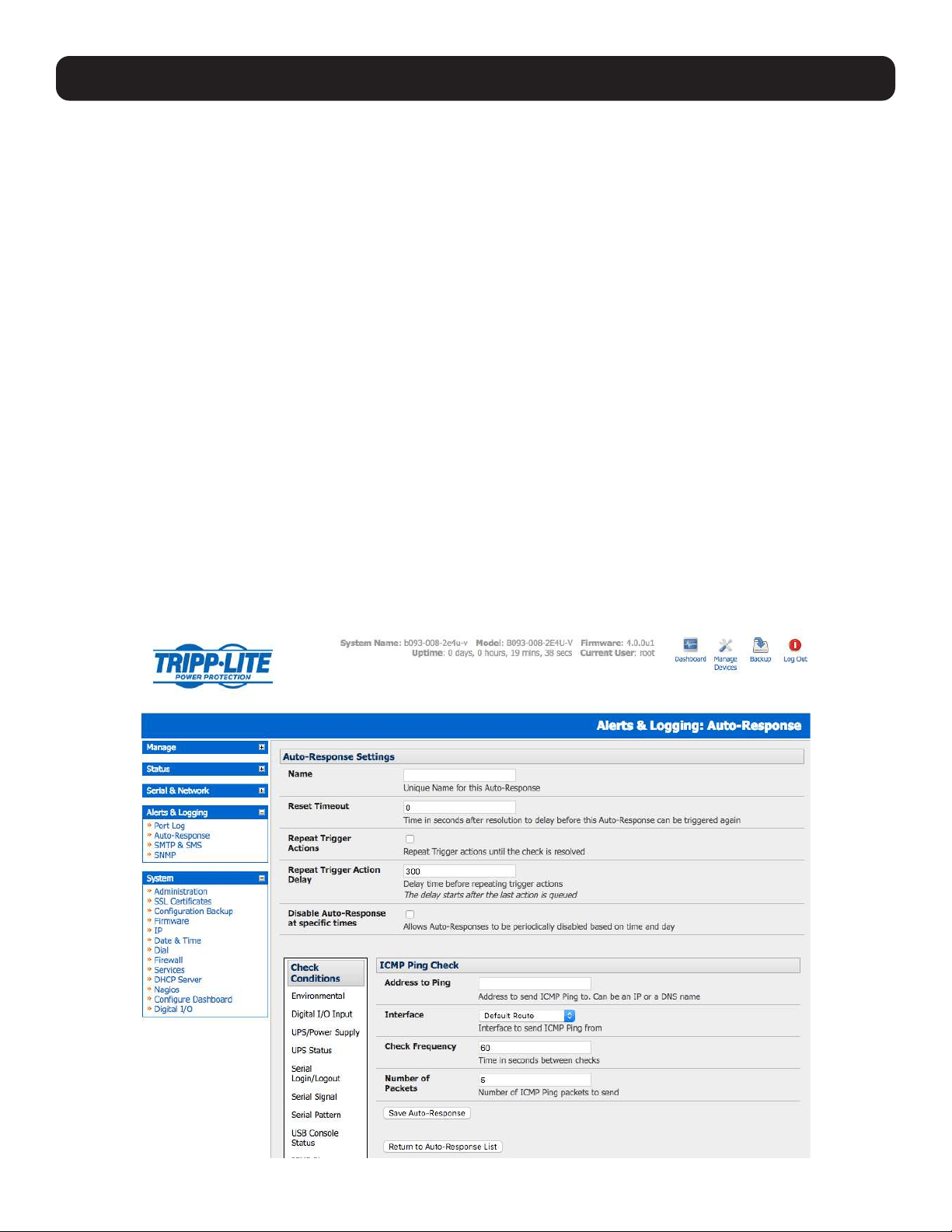
131
To monitor USB ports:
• Click USB Console Status as the Check Condition.
• Check the Trigger on Connect checkbox, the Trigger on Disconnect checkbox, or both checkboxes to set which actions
trigger the auto-response.
• Check each USB port to be monitored (or click the Select/Unselect all Ports checkbox to select or deselect all USB ports).
• Click the Save Auto-Response button.
• Select an option from the Add Trigger Action list.
• Enter a unique action name for the trigger action being created.
• Set an action delay time. By default, this is 0 seconds.
• Enter the specific details of the selected action. For example, the Send Email action requires a recipient email address and
allows for a subject and email text.
• Click the Save New Action button.
Note: USB console status checks are not resolvable.Trigger actions run but resolve actions do not.
7.2.7 ICMP Ping
To use a ping result as the auto-response trigger event:
• Click on ICMP Ping as the Check Condition.
• Specify which Address to Ping (i.e. IP address or DNS name to send ICMP Ping to) and which Interface to send ICMP Ping
from (e.g. Management LAN or Wireless network).
• Set the Check Frequency (i.e. the time in seconds between checks) and the Number of ICMP Ping packets to send.
• Check Save Auto-Response.
7. Alerts, Auto-Response and Logging

132
7. Alerts, Auto-Response and Logging
7.2.8 Link Layer Discovery Protocol (LLDP)
The Link Layer Discovery Protocol (LLDP) is a protocol that allows system administrators to glean information about devices
physically connected to managed switches.
Using LLDP
The LLDP service is enabled through the System > Services page. When the service is enabled, the lldpd daemon is loaded
and running. The Service Access tab controls which network interfaces are monitored by the lldpd daemon.
When LLDP is granted access to an interface, it will use that interface, even if the interface has been disabled via System >
IP.
LLDP neighbors are visible through the Status > LLDP Neighbors page. This page shows neighbors are recognized and
indicates the information the console manager is sending.
Note: Although the LLDP service can be granted access to non-Ethernet interfaces (for example, G3, G4 and PSTN dial-up interfaces), it
currently ignores non-Ethernet interfaces.
Customising LLDP
The lldpcli shell client interacts with and configures the running LLDP service.
Persistent custom configuration changes can be added to the system through configuration files placed in /etc/config/lldpd.d/.
Custom configuration files — which must have filenames ending with .conf — will be read and executed by lldpcli when the
LLDP service starts.
Note: The /etc/ directory is read-only on Tripp Lite hardware. Most default configuration files otherwise stored in /etc/ are, on Tripp Lite
hardware, in /etc/config/, which is writeable.
The default lldpd configuration file — lldpd.conf — is stored in /etc/config/ on Tripp Lite hardware. However, it is not safe as a store of
custom configuration details. There are circumstances in which this file is regenerated automatically, in which case all customizations will be
lost.
The etc/config/lldpd.d/ directory, which is also writable and created on first boot, is safe to write to. Any Custom LLDP configurations must be
stored as *.conf files in this directory.
Security
When enabled, LLDP frames issued by a Tripp Lite Console Manager will reveal sensitive information, such as hostname and
firmware version.
However, LLDP frames are not passed through by 802.3ab compliant switches, and Tripp Lite Console Managers have the
LLDP service disabled by default.
Documentation
Both lldpd and lldpcli have standard manual pages. However, due to space constraints, these manual pages are not shipped
with Tripp Lite hardware.
Both manual pages are available on the lldpd project web-site however:
man lldpd.
man lldpcli.
Note: Tripp Lite uses lldpd 0.9.2.
7.2.9 Cellular Data
This check monitors the inbound and outbound aggregate data traffic through the cellular modem as an auto-response trigger
event.
• Click on Cellular Data as the Check Condition.
Note: Before configuring cellular data checks in auto-response, the internal cellular modem must be configured and detected by the
console server.

133
7.2.10 Custom Check
This check allows users to run an assigned custom script with assigned arguments whose return value is used as an auto-
response trigger event:
• Click on Custom Check as the Check Condition.
• Create an executable trigger check script file (e.g. /etc/config/test.sh):
#!/bin/sh
logger “A test script”
logger Argument1 = $1
logger Argument2 = $2
logger Argument3 = $3
logger Argument4 = $4
if [ -f /etc/config/customscript.0 ]; then
rm /etc/config/customscript.0
exit 7
fi
touch /etc/config/customscript.0
exit 1
Refer to the online FAQ for a sample web page html and other script file templates.
• Enter the Script Executable file name (e.g. /etc/config/test.sh).
• Set the Check Frequency (i.e. the time in seconds between re-running the script) and the Script Timeout (i.e. the
maximum run-time for the script).
• Specify the Successful Return Code. An auto-response is triggered if the return code from the script is not this value.
• Enter Arguments that are to be passed to the script (e.g., with a web page html check script, these Arguments may specify
the web page address/DNS and user logins).
• Check Save Auto-Response.
7. Alerts, Auto-Response and Logging
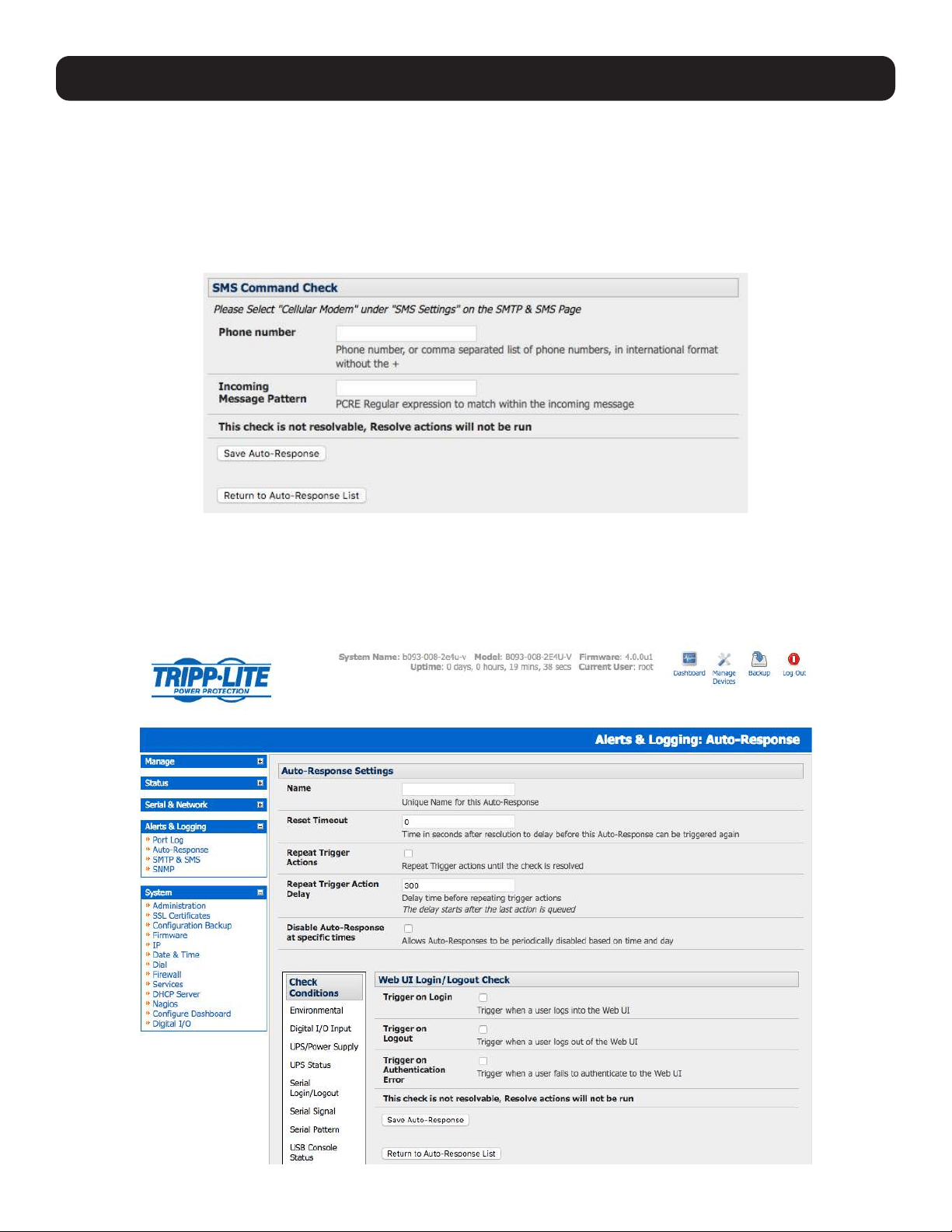
134
7. Alerts, Auto-Response and Logging
7.2.11 SMS Command
An incoming SMS command from an assigned caller can trigger an auto-response:
• Click on SMS Command as the Check Condition.
• Specify which Phone Number (in international format) of the phone sending the SMS message. For multiple trusted SMS
sources, separate the numbers with a comma.
• Set the Incoming Message Pattern (PCRE regular expression) to match to create a trigger event.
Note: The SMS command trigger condition can only be set if an internal cellular modem is detected.
7.2.12 Log In/Out Check
To configure web login/out as the trigger event:
• Click on the Web UI Authentication as the Check Condition.
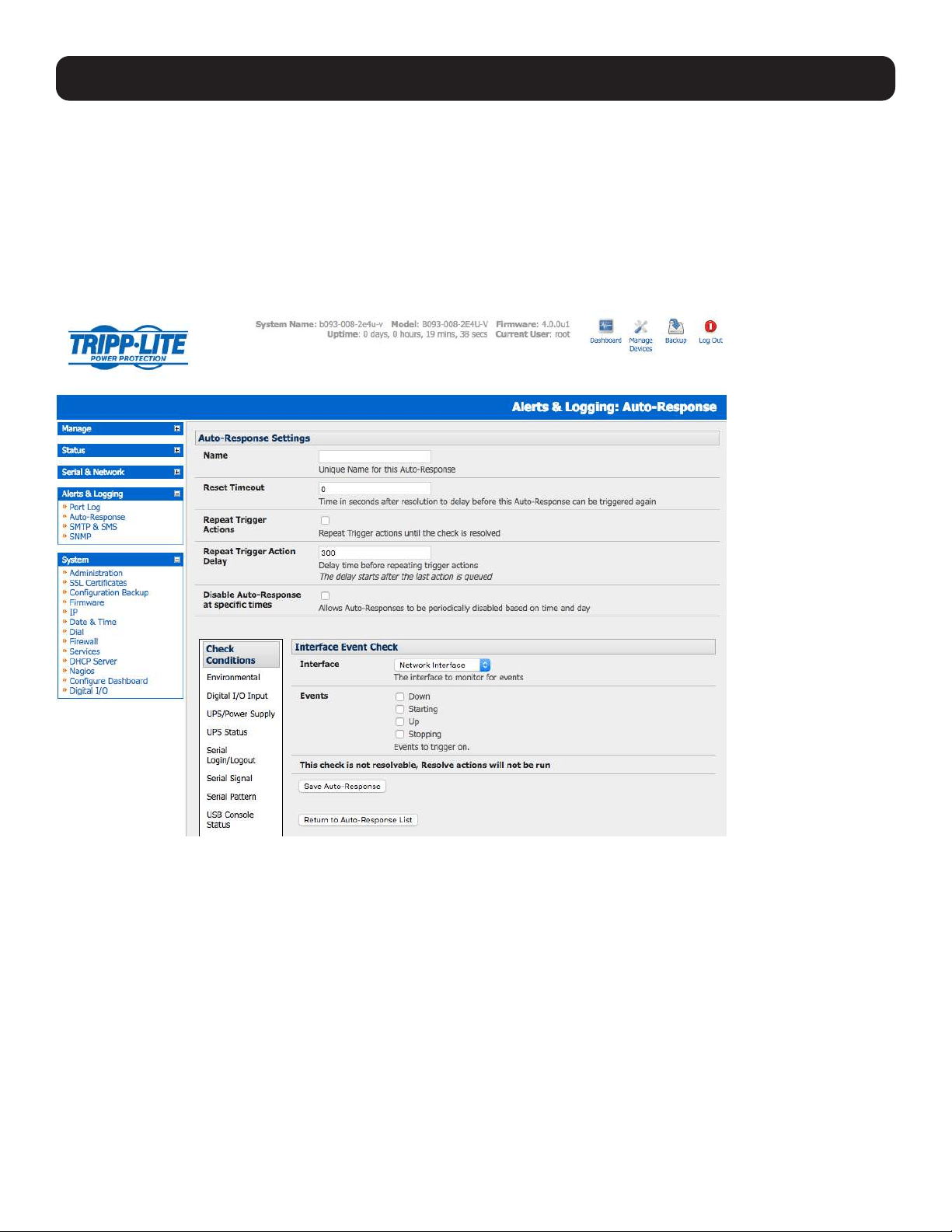
135
• Check Trigger on Login (Logout) to trigger when a user logs into (or out of) the Web UI.
• Check Trigger on Authentication Error to trigger when a user fails to authenticate to the Web UI.
Note: This check is not resolvable. Resolve actions will not run.
7.2.13 Network Interface Event
You may wish to configure a change in the network status as the trigger event (e.g., to send an alert or restart a VPN tunnel
connection):
• Click on Network Interface as the Check Condition.
• Select the Interface (Ethernet /Failover OOB Interface or Modem or VPN) to monitor.
• Check what type of network interface Event to trigger on (interface Down, Starting, Up or Stopping).
Note: This check is not resolvable. Resolve actions will not run.
7. Alerts, Auto-Response and Logging
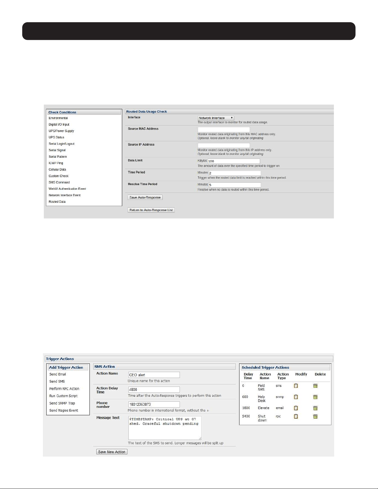
136
7. Alerts, Auto-Response and Logging
7.2.14 Routed Data Usage Check
This check monitors the specified input interface for data usage being routed through the console server and out through
another interface, such as the Internal Cellular Modem.
Routed data usage check is particularly useful in IP Passthrough mode to detect when the downstream router has failed over
and is now routing via the console server’s modem as a backup connection.
This check may be configured with these parameters:
• The console server’s incoming Interface to monitor.
• An optional Source MAC/IP Address, to monitor traffic from a specific host (e.g., the downstream router).
• A Data Limit threshold, the auto-response will trigger when this is hit in the specified Time Period.
• The auto-response will resolve if no matching data is routed for the Resolve Period.
7.3 Trigger Actions
To configure the sequence of actions to be taken in the event of the trigger condition:
• For an assigned auto-response with a defined check condition, click on Add Trigger Action (e.g. Send Email or Run
Custom Script) to select the action type to be taken. Then configure the selected action (as detailed in the following
sections).
• Each action is configured with an assigned Action Delay Time which specifies how long (in seconds) after the auto-
response trigger event to wait before performing the action. You can add follow-on actions to create a sequence of actions
that will be taken in the event of the one trigger condition.
• To edit (or delete) an existing action, click the Modify (or Delete) icon in the Scheduled Trigger Action table.

137
Note: A message text can be sent with Email, SMS and Nagios actions. This configurable message can include selected values:
$AR_TRIGGER_VAL = the trigger value for the check e.g. for UPS Status, it could be onbatt or battlow
$AR_VAL = the value returned by the check e.g. for ups status, it could be online/onbatt/battlow
$AR_CHECK_DEV = the device name of the device being checked e.g. for Alarm, the alarm name
$TIMESTAMP = the current timestamp
$HOSTNAME = the hostname of the console server
The default message text is: $TIMESTAMP: This action was run - Check details: value $AR_VAL vs trigger value $AR_TRIGGER_VAL.
7.3.1 Send Email
Click on Send Email as the Add Trigger Action. Enter a unique Action Name and set the Action Delay Time
Specify the Recipient Email Address for whom to send this email and the Subject of the email. For multiple recipients, you
can enter comma-separated addresses.
Edit the Email Text message to send. Click Save New Action.
Note: An SMS alert can also be sent via an SMTP (email) gateway. You will need to specify the Recipient Email Address in the format
specified by the gateway provider (e.g,. for T-Mobile it is [email protected]).
7.3.2 Send SMS
Click on Send SMS as the Add Trigger Action. Enter a unique Action Name and set the Action Delay Time.
Specify the Phone number that the SMS will be sent to in international format (without the +).
Edit the Message Text to send and click Save New Action.
Note: The SMS alert can only be sent if there is an internal cellular modem attached. However, an SMS alert can also be sent via SMTP
SMS gateway, as described above.
7.3.3 Perform RPC Action
Click on Perform RPC Action as the Add Trigger Action. Enter a unique Action Name and set the Action Delay Time
Select a power Outlet and specify the Action to be performed (power ON, OFF or Cycle).
Click Save New Action.
7.3.4 Run Custom Script
Click on Run Custom Script as the Add Trigger Action. Enter a unique Action Name, and set the Action Delay Time.
Create a script file to execute when this action is triggered and enter the Script Executable file name (e.g., /etc/config/
action.sh).
Set the Script Timeout (the maximum run-time for the script). Leave as 0 for unlimited.
Enter any Arguments that are to be passed to the script and click Save New Action.
7.3.5 Send SNMP Trap
Click on Send SNMP Trap as the Add Trigger Action. Enter a unique Action Name, and set the Action Delay Time.
Note: SNMP Trap actions are valid for Serial, Environmental, UPS and Cellular data triggers.
7. Alerts, Auto-Response and Logging
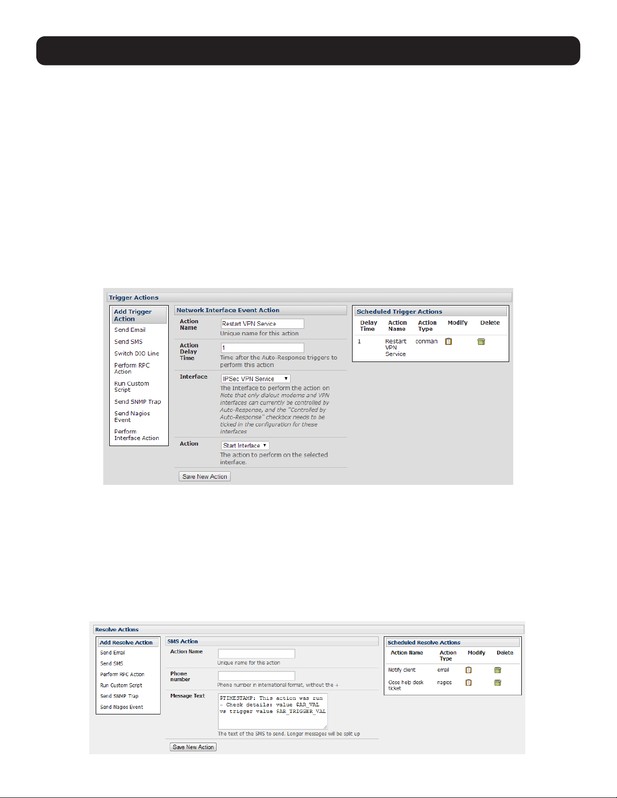
138
7. Alerts, Auto-Response and Logging
7.3.6 Send Nagios Event
Click on Send Nagios Event as the Add Trigger Action. Enter a unique Action Name, and set the Action Delay Time.
Edit the Nagios Event Message text to display on the Nagios status screen for the service.
Specify the Nagios Event State (OK, Warning, Critical or Unknown) to return to Nagios for this service.
Click Save New Action.
Note: To notify the central Nagios server of Alerts, NSCA must be enabled under System: Nagios and Nagios must be enabled for each
applicable host or port.
7.3.7 Perform Interface Action
Click on Perform Interface Action as the Add Trigger Action. Enter a unique Action Name, and set the Action Delay
Time.
Select the Interface (Modem or VPN service) and the Action (Start or Stop Interface) to be taken. You may wish to start an
IPsec VPN service in response to an incoming SMS, or set up an OpenVPN tunnel whenever your Tripp Lite device fails over to
use the cellular connection.
Note: If any IPsec service or OpenVPN tunnel is to be controlled by the Network Interface Event Action, you will need to have checked the
Control by Auto-Response box when configuring that service. If selected, the default state for the VPN tunnel / service will be down.
7.4 Resolve Actions
Actions can also be scheduled for when a trigger condition has been resolved:
• For an assigned auto-response with a defined trigger check condition, click on Add Resolve Action (e.g., Send Email or
Run Custom Script) to select the action type to be taken.
Note: Resolve Actions are configured exactly the same as Trigger Actions, except the designated Resolve Actions are all executed on
resolution of the trigger condition and there are no Action Delay Times set.
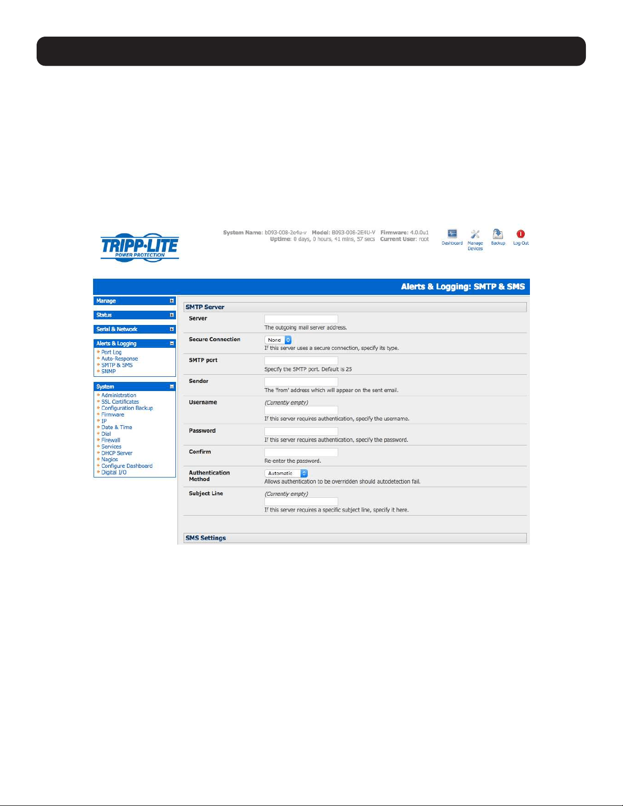
139
7.5 Configure SMTP, SMS, SNMP and/or Nagios Service for
Alert Notifications
The auto-response facility enables remote alerts to be sent as Trigger and Resolve Actions. Before such alert notifications can
be sent, you must configure the assigned alert service.
7.5.1 Send Email Alerts
The console server uses SMTP (Simple Mail Transfer Protocol) for sending the email alert notifications. To use SMTP, the
Administrator must configure a valid SMTP server for sending the email:
• Select Alerts & Logging: SMTP & SMS.
• In the SMTP Server field, enter the IP address of the outgoing mail Server.
• If this mail server uses a Secure Connection, specify its type. You may also specify the IP port to use for SMTP. The default
SMTP Port is 25.
• You may enter a Sender email address which will appear as the “from” address in all email notifications sent from this
console server. Many SMTP servers check the sender’s email address with the host domain name to verify the address as
authentic. It may be useful to assign an email address for the console server, such as [email protected].
• You may also enter a Username and Password if the SMTP server requires authentication.
• Similarly can specify the specific Subject Line that will be sent with the email.
• Click Apply to activate SMTP.
7. Alerts, Auto-Response and Logging
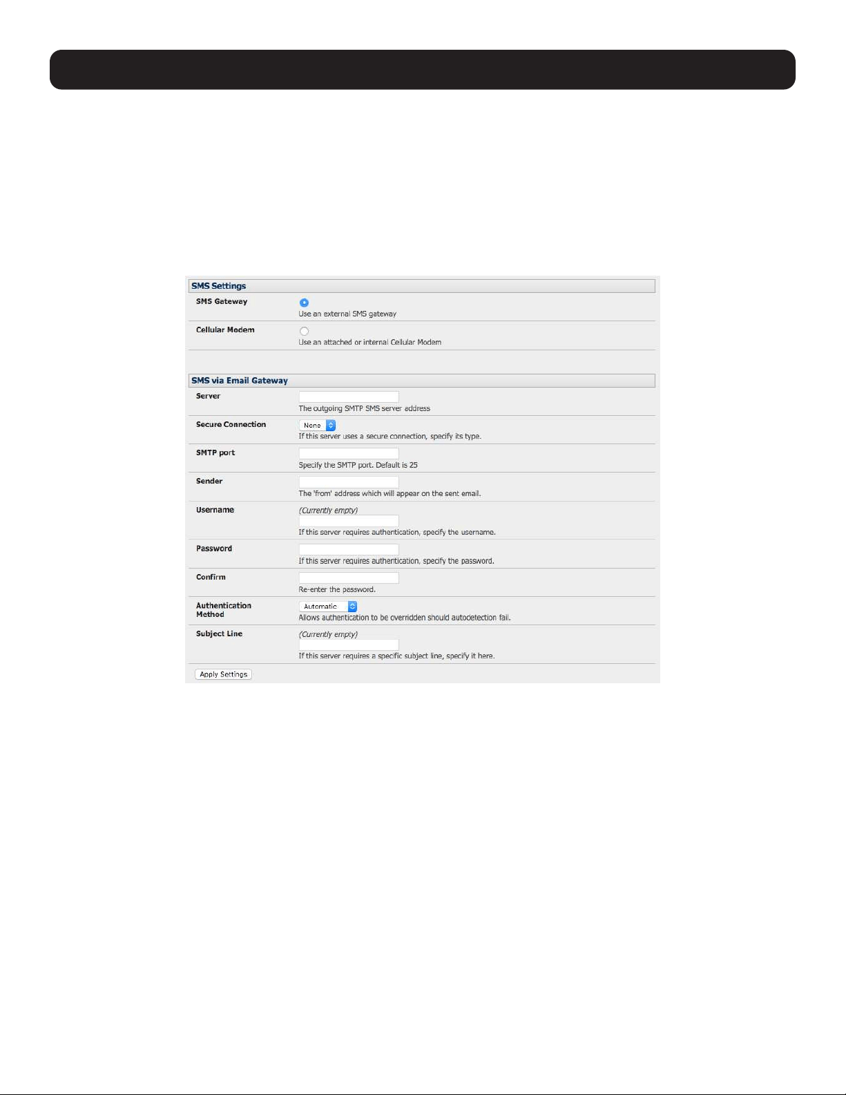
140
7. Alerts, Auto-Response and Logging
7.5.2 Send SMS Alerts
With any model console server, you can use email-to-SMS services to send SMS alert notifications to mobile devices. Almost
all mobile phone carriers provide an SMS gateway service that forwards email to mobile phones on their networks. A wide
selection of SMS gateway aggregators provide email to SMS forwarding to phones on any carrier.
Alternately, if your console server has an embedded or externally attached cellular modem, you will be given the option to send
the SMS directly over the carrier connection.
SMS via Email Gateway
To use SMTP SMS, the Administrator must configure a valid SMTP server for sending the email:
• In the SMTP Settings field in the Alerts & Logging: SMTP & SMS menu, select SMS Gateway. An SMS via Email
Gateway field will appear.
• Enter the IP address of the outgoing mail Server SMS gateway.
• Select a Secure Connection (if applicable) and specify the SMTP port to be used (if other than the default port 25).
• You may also enter a Sender email address which will appear as the “from” address in all email notifications sent from this
console server. Some SMS gateway service providers only forward email to SMS when the email has been received from
authorized senders. You may need to assign a specific authorized email address for the console server.
• You may also enter a Username and Password, as some SMS gateway service providers use SMTP servers that require
authentication.
• Similarly, you can specify the specific Subject Line that will be sent with the email. Generally, the email subject will contain
a truncated version of the alert notification message (which is contained in full in the body of the email). Some SMS
gateway service providers require blank subjects or require specific authentication headers to be included in the subject line
• Click Apply Settings to activate SMS SMTP connection.
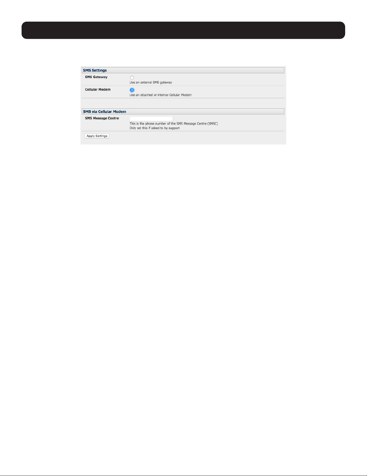
141
7. Alerts, Auto-Response and Logging
SMS via Cellular Modem
To use an attached or internal cellular modem for SMS, the Administrator must enable SMS:
• Select Cellular Modem in the SMS Settings field.
• Check Receive Messages to enable incoming SMS messages to be received. A custom script will be called on receipt of
incoming SMS messages.
• You may need to enter the phone number of the carrier’s SMS Message Center (only if advised by your carrier or tech
support).
• Click Apply Settings to activate SMS SMTP connection.
Note: The option to directly send SMS alerts via cellular modem was included in the Management GUI in firmware version 3.4. Advanced
console servers have had the gateway software (SMS Server Tools 3) embedded since version 3.1. However, this can only be accessed from
the command line to send SMS messages.
7.5.3 Send SNMP Trap Alerts
The Administrator can configure the Simple Network Management Protocol (SNMP) agent that resides on the console server to
send SNMP trap alerts to an NMS management application:
• Select Alerts & Logging: SNMP.
Notes: In firmware versions 3.10.2 and above, new SNMP status and trap MIBS provide more and better-structured SNMP status and traps
from console servers. There is an option in the SNMP menu to Use Legacy Notifications for the SNMP traps. Selecting this option means
the console server will send SNMP traps that are compatible with those sent in older firmware before the new MIBS were added, ensuring
that the firmware upgrade will not disrupt existing SNMP management.
When upgrading from old firmware that does not support the newer SNMP MIBs/traps (versions before 3.10.2) to firmware that does
support the new MIBs/traps:
• If the SNMP service was enabled and an SNMP manager was configured before upgrading the firmware, the console server will be
configured to use the legacy traps after upgrading.
• If the SNMP service was not enabled or SNMP manager was not configured before the upgrade, then the console server will be configured
to use the new SNMP traps after the upgrade (this will not have any effect until the SNMP service is turned on and an SNMP manager is
configured).
• When starting up in the new firmware after a configuration erase, the console server will be configured to use the new SNMP traps.
• When upgrading from a firmware version that supports the new traps to a newer version that supports the new traps, the use legacy traps
setting should remain the same, as no checking on snmp service/manager configuration is needed.
• Select the Primary SNMP Manager tab. The Primary and Secondary SNMP Manager tabs configure where and how
outgoing SNMP alerts and notifications are sent. If you require your console server to send alerts via SNMP, then a Primary
SNMP Manager must be configured (at a minimum). Optionally, a second SNMP Network Manager with its own SNMP
settings can be specified on the Secondary SNMP Manager tab.
Note: All console servers can also be configured to provide status information on demand using snmpd. This SNMP agent is configured
using the SNMP Service Detail on Alerts & Logging: SNMP (refer to 15. Advanced Configuration for more information).
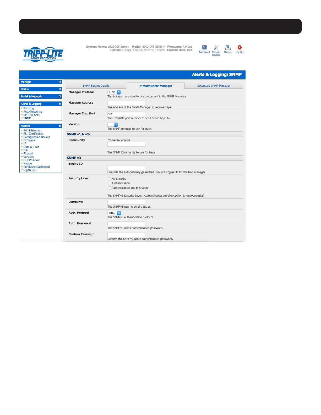
142
7. Alerts, Auto-Response and Logging
• Select the Manager Protocol. SNMP is generally a UDP-based protocol, though infrequently it uses TCP instead.
• Enter the host address of the SNMP Network Manager into the Manager Address field.
• Enter the TCP/IP port number into the Manager Trap Port field (default =162).
• Select the Version to be used. The console server SNMP agent supports SNMP v1, v2 and v3.
• Enter the Community name for SNMP v1 or SNMP v2c. At a minimum, a community needs to be set for either SNMP v1 or
v2c traps to work. An SNMP community is the group to which devices and management stations running SNMP belong. It
helps define where information is sent. SNMP default communities are private for Write and public for Read.
• Configure SNMP v3 (if required). For SNMP v3 messages, the user’s details and security level must match what the
receiving SNMP Network Manager is expecting. SNMP v3 mandates that the message will be rejected unless the SNMPv3
user sending the trap already exists in the user database on the SNMP Manager. The user database in a SNMP v3
application is actually referenced by a combination of the Username and the Engine ID for the given SNMP application you
are talking to.
o Enter the Engine ID for the user sending messages as a hex number e.g. 0x8000000001020304.
o Specify the Security Level. The level of security has to be compatible with the settings of the remote SNMP Network
Manager.
noAuthNoPriv No authentication or encryption.
authNoPriv Authentication only. An authentication protocol (SHA or MD5) and password will be required.
authPriv Uses both authentication and encryption. This is the highest level of security and requires an encryption
protocol (DES or AES) and password in addition to the authentication protocol and password.

143
o Complete the Username. This is the Security Name of the SNMPv3 user sending the message. This field is mandatory
and must be completed when configuring the console server for SNMPv3.
o An Authentication Protocol (SHA or MD5) and Authentication Password must be given for a Security Level of either
authNoPriv or authPriv. The password must contain at least 8 characters to be valid.
o A Privacy Protocol (DES or AES) must be specified for the authPriv level of security to be used as the encryption
algorithm. AES is recommended for stronger security. A password of at least 8 characters must be provided for encryption
to work.
• Click Apply.
Note: Console servers with firmware version 3.0 (and later) also embed the net-snmpd daemon which can accept SNMP requests from
remote SNMP management servers and provides information on alert / serial / device status (refer to 15.5 SNMP Status Reporting for
more information). Console servers with firmware earlier than V3.3 could only configure a Primary SNMP server from the Management
Console. Refer 15.5 SNMP Status Reporting for details on configuring the snmptrap daemon to send traps/notifications to multiple remote
SNMP servers.
7.5.4 Send Nagios Event Alerts
To notify the central Nagios server of Alerts, NSCA must be enabled under System: Nagios and Nagios must be enabled
for each applicable host or port under Serial & Network: Network Hosts or Serial & Network: Serial Ports (refer to 10.
Nagios Integration).
7.6 Logging
The console server can maintain log records of auto-response, access and communications events (with the console server
and the attached serial, network and power devices).
A log of all system activity is also maintained by default, as is a history of the status of any attached environmental monitors.
7. Alerts, Auto-Response and Logging
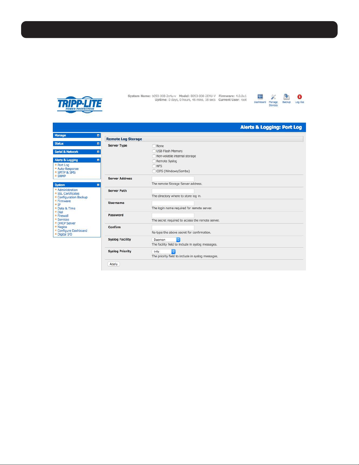
144
7. Alerts, Auto-Response and Logging
7.6.1 Log Storage
Before activating any Event, Serial, Network or UPS logging, you must specify where those logs are to be saved. These records
are stored off-server or in the Tripp Lite gateway’s USB flash memory.
Select the Alerts & Logging: Port Log menu option and specify the Server Type to be used, as well as the details to enable
log server access.
From the Manage: Devices menu, the Administrator can view serial, network and power device logs stored in the console
reserve memory (or flash USB). The User will only see logs for the managed devices they (or their group) have been given
access privileges for (refer to section 13. Management).
Event logs on the USB can be viewed using the web terminal or by ssh/telnet connecting to the console server.
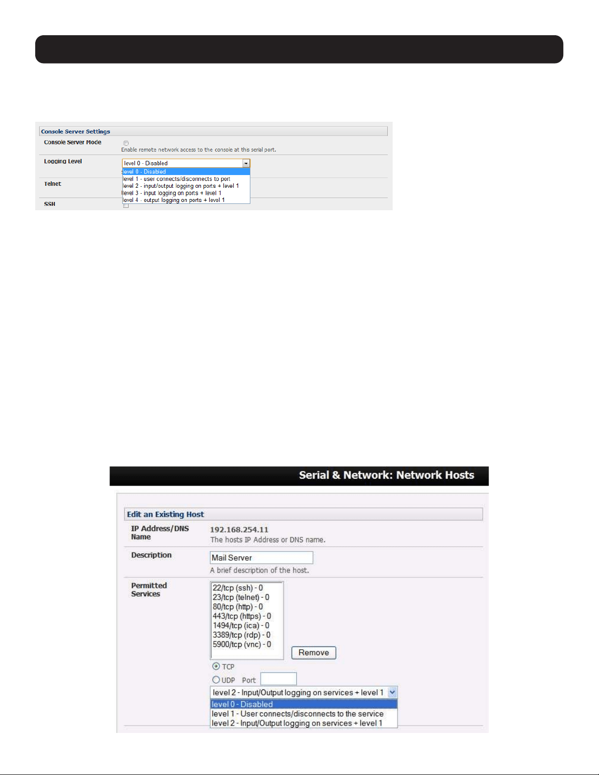
145
7. Alerts, Auto-Response and Logging
7.6.2 Serial Port Logging
In Console Server mode, activity logs can be maintained of all serial port activity. To specify which serial ports are to have
activities recorded and to what level data is to be logged:
• Select Serial & Network: Serial Port. Edit the port to be logged.
• Specify the Logging Level of for each port as:
Level 0 Turns off logging for the selected port.
Level 1 Logs all user connection events to the port.
Level 2 Logs all data transferred to and from the port and all changes in hardware flow control status and all user
connection events.
Level 3 Logs all data transferred from the port and all changes in hardware flow control status and all user connection
events.
Level 4 Logs all data transferred to the port, all changes in hardware flow control status and all user connection events.
• Click Apply
Note: A cache of the most recent 8K of logged data per serial port is maintained locally (in addition to the logs, which are transmitted for
remote/USB flash storage). To view the local cache of logged serial port data select Manage: Port Logs.
7.6.3 Network TCP and UDP Port Logging
The console server supports optional logging of access to and communications with network-attached hosts.
• For each host, when you set up the permitted services that are authorized to be used, you also must set up the level of
logging that is to be maintained for each service.
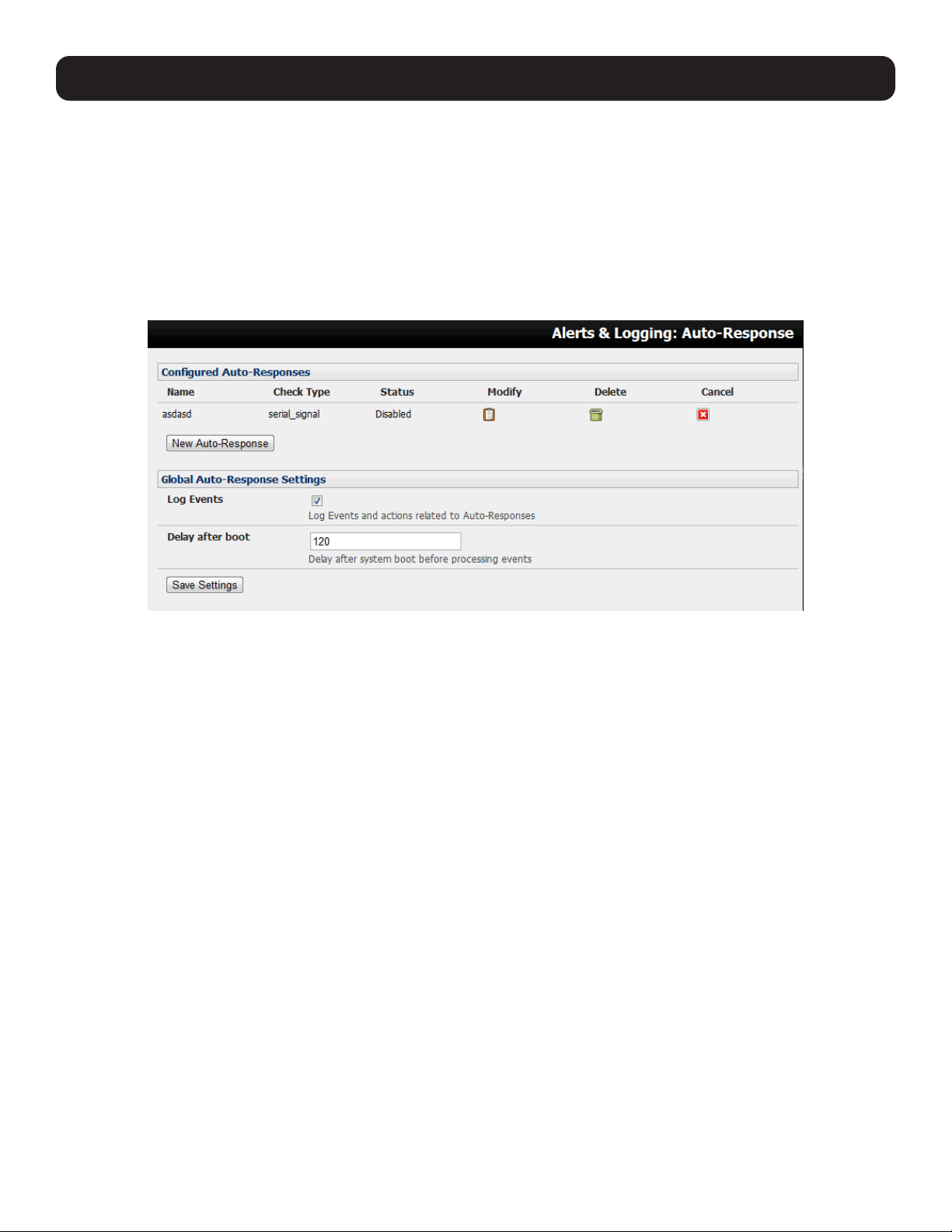
146
7. Alerts, Auto-Response and Logging
• Specify the logging level that is to be maintained for that particular TDC/UDP port/service on that particular host:
Level 0 Turns off logging for the selected TDC/UDP port to the selected host.
Level 1 Logs all connection events to the port.
Level 2 Logs all data transferred to and from the port.
• Click Add, then click Apply.
7.6.4 Auto-Response Event Logging
Check Log Events on Alerts & Logging: Auto-Response to enable logging for all auto-response activities.
7.6.5 Power Device Logging
The console server also logs access and communications with network-attached hosts and maintains a history of the UPS and
PDU power status.
To activate and set the desired levels of logging for each serial, refer to 7.4 Resolve Actions; for network ports, refer to 7.5
Configure SMTP, SMS, SNMP and/or Nagios Service for Alert Notifications; and for Power, Environment and Digital I/O
UPS, refer to section 8.
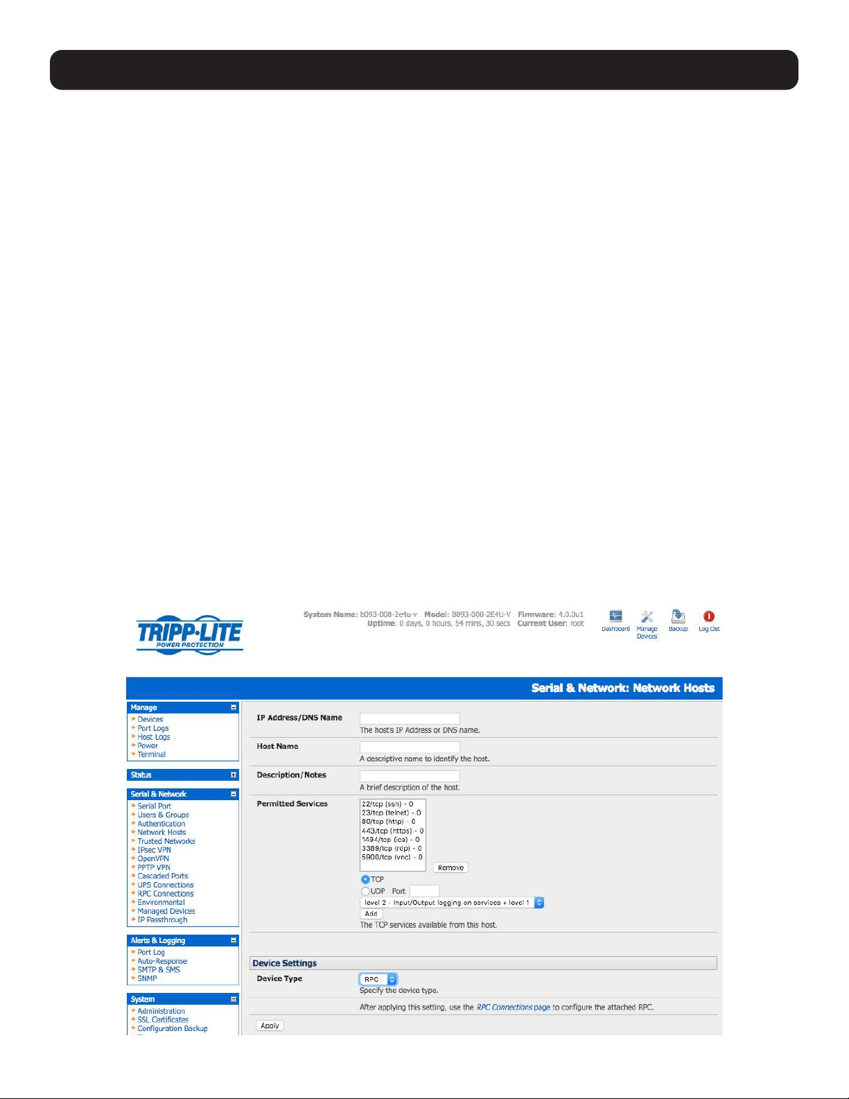
147
8. Power, Environment and Digital I/O
Console servers manage Remote Power Control devices (PDUs and IPMI devices) and Uninterruptible Power Supplies (UPS).
They also monitor remote operating environments using Environmental Monitoring Devices (EMDs) and sensors and can
provide digital I/O control.
8.1 Remote Power Control (RPC)
The console server management console monitors and controls Remote Power Control (RPC) devices using the embedded
PowerMan and Network UPS Tools, open source management tools, and Tripp Lite’s power management software. RPCs
include power distribution units (PDUs) and IPMI power devices.
Serial PDUs can be controlled using their command line console, so you could manage the PDU through the console server
using a remote telnet client. Also, you could use proprietary software tools no doubt supplied by the vendor. This generally runs
on a remote Windows PC and you could configure the console server serial port to operate with a serial COM port redirector
in the PC (refer to section 4. Serial Port, Host, Device and User Configuration). Similarly, network-attached PDUs can
be controlled with a browser (e.g., with SDT as detailed in section 6.3 SDT Connector Management Console), an SNMP
management package, or using the vendor-supplied control software. Servers and network-attached devices with embedded
IPMI service processors or BMCs are supplied with their own management tools (like SoL) to provide secure management
when connected using with SDT Connector.
For simplicity, these devices can be controlled through one window with the Management Console’s RPC remote power control
tools.
8.1.1 RPC Connection
Serial and network-connected RPCs must first be connected to and configured to communicate with the console server:
• For serial RPCs, connect the PDU to the selected serial port on the console server. From the Serial and Network: Serial
Port menu, configure the Common Settings of that port with the RS-232 properties required by the PDU (refer to 4.1.1
Common Settings). Select RPC as the Device Type.
• Similarly, for each network-connected RPC go to Serial & Network: Network Hosts menu and configure the RPC as a
connected host by specifying it as Device Type: RPC and clicking Apply (refer to 4.4 Network Hosts).
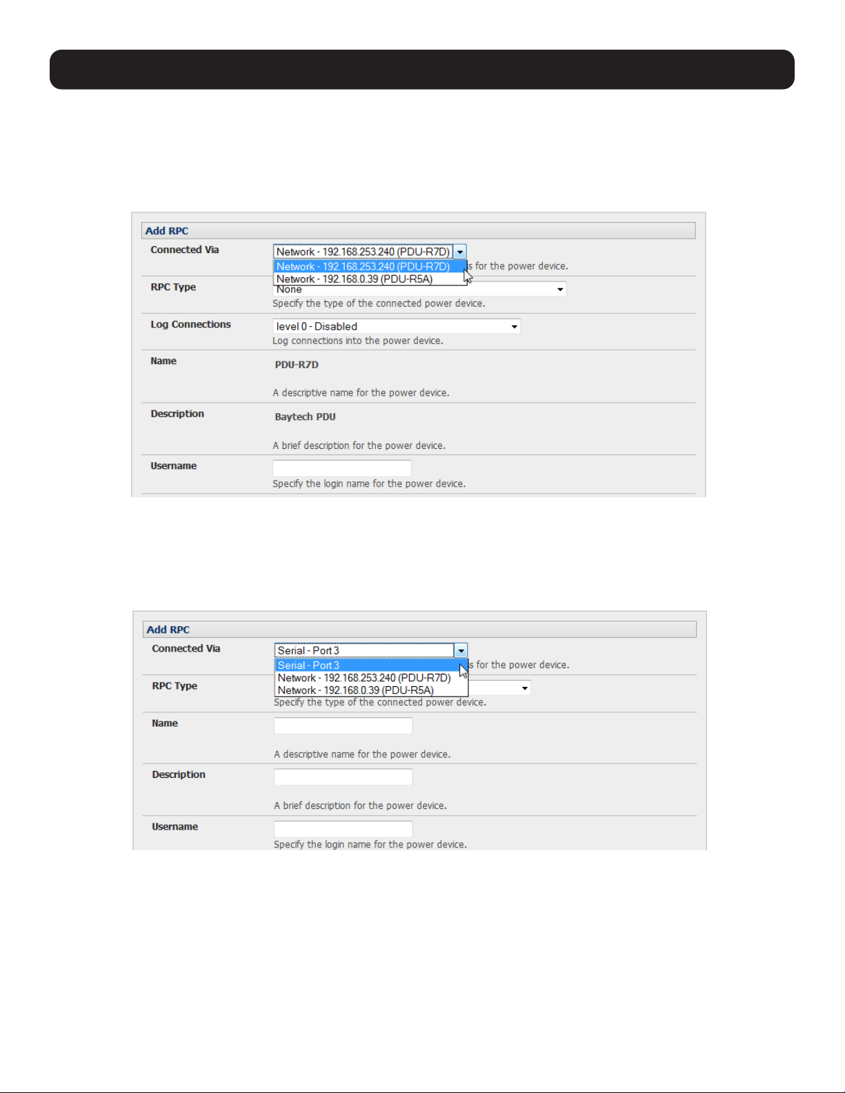
148
8. Power, Environment and Digital I/O
• Select the Serial & Network: RPC Connections menu. This will display all RPC connections that have already been
configured.
• Click Add RPC.
• Connected Via presents a list of serial ports and network host connections you have set up with device type RPC (but have
yet to connect to a specific RPC device):
o When you select Connect Via for a Network RPC connection, the corresponding host name/description you set for that
connection will be entered as the Name and Description for the power device.
o Alternately, if you select to Connect Via a serial connection, you will need to enter a Name and Description for the
power device.
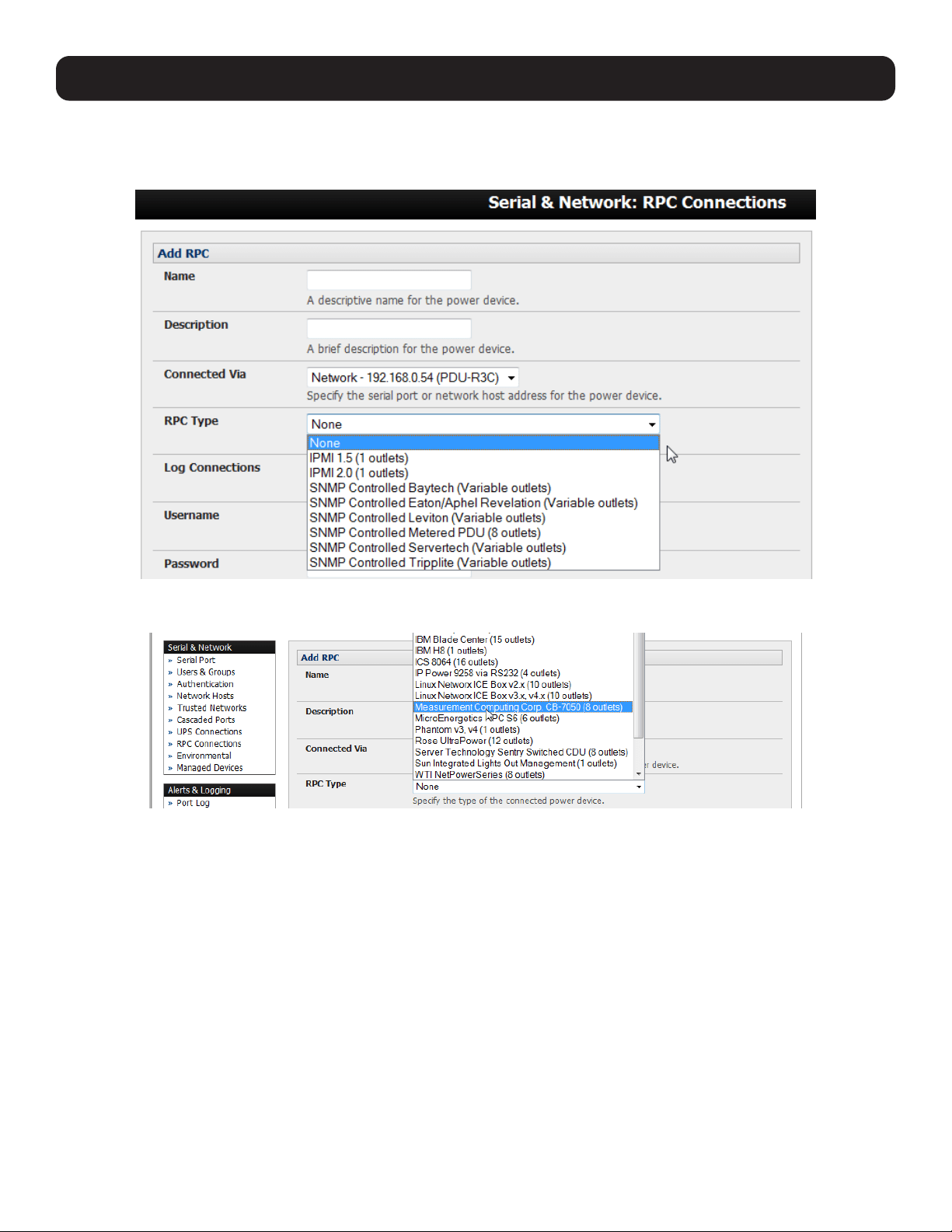
149
• Select the appropriate RPC Type for the PDU (or IPMI) being connected:
o If you are connecting to the RPC via the network, you will be presented with the IPMI protocol options and the SNMP RPC
Types currently supported by the embedded Network UPS Tools.
o If you are connecting to the RPC by a serial port, you will be presented with all the serial RPC types currently supported by
the embedded PowerMan and Tripp Lite’s power manager:
• Enter the Username and Password used to log in to the RPC.
Note: These login credentials are not related. The users and access privileges you will have configured in Serial & Networks: Users &
Groups.
8. Power, Environment and Digital I/O
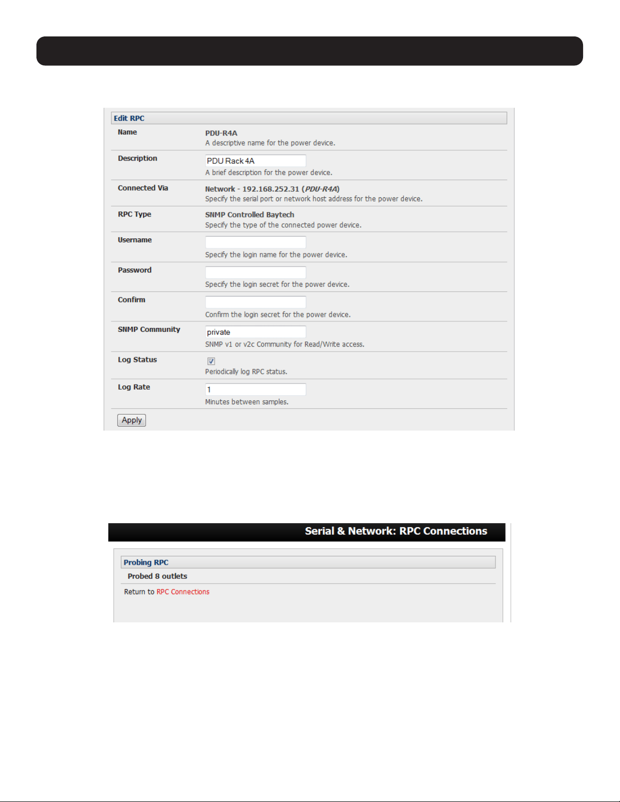
150
8. Power, Environment and Digital I/O
• If you selected SNMP protocol, you will need to enter the SNMP v1 or v2c Community for Read/Write access (by default this
is set to “private”).
• Check Log Status and specify the Log Rate (minutes between samples) if you wish the status from this RPC to be logged.
These logs can be viewed from the Status: RPC Status screen.
• Click Apply.
• For SNMP PDUs, the console server will now probe the configured RPC to confirm the RPC Type matches and will report the
number of outlets it finds that can be controlled. If unsuccessful, it will report Unable to probe outlets and you will need to
check the RPC settings or network/serial connection.
• For serially connected RPC devices, a new managed device with the same name as given to the RPC will be created. The
console server will then configure the RPC with the number of outlets specified in the selected RPC Type or will query the
RPC itself for this information.
Note: Tripp Lite’s console servers support most network and serial PDUs. If your PDU is not on the default list, support can be added directly
(refer to 14. Configuration from the Command Line) or by having the PDU support added to either the Network UPS Tools or PowerMan
open source projects.
IPMI service processors and BMCs can be configured so all authorized users can use the management console to remotely cycle power and
reboot computers, even when their operating system is unresponsive. To set up IPMI power control, the Administrator will first enter the IP
address/domain name of the BMC or service processor (e.g. a Dell DRAC) in Serial & Network: Network Hosts, then in Serial & Network:
RPC Connections. The RPC Type should be IPMI1.5 or 2.0.
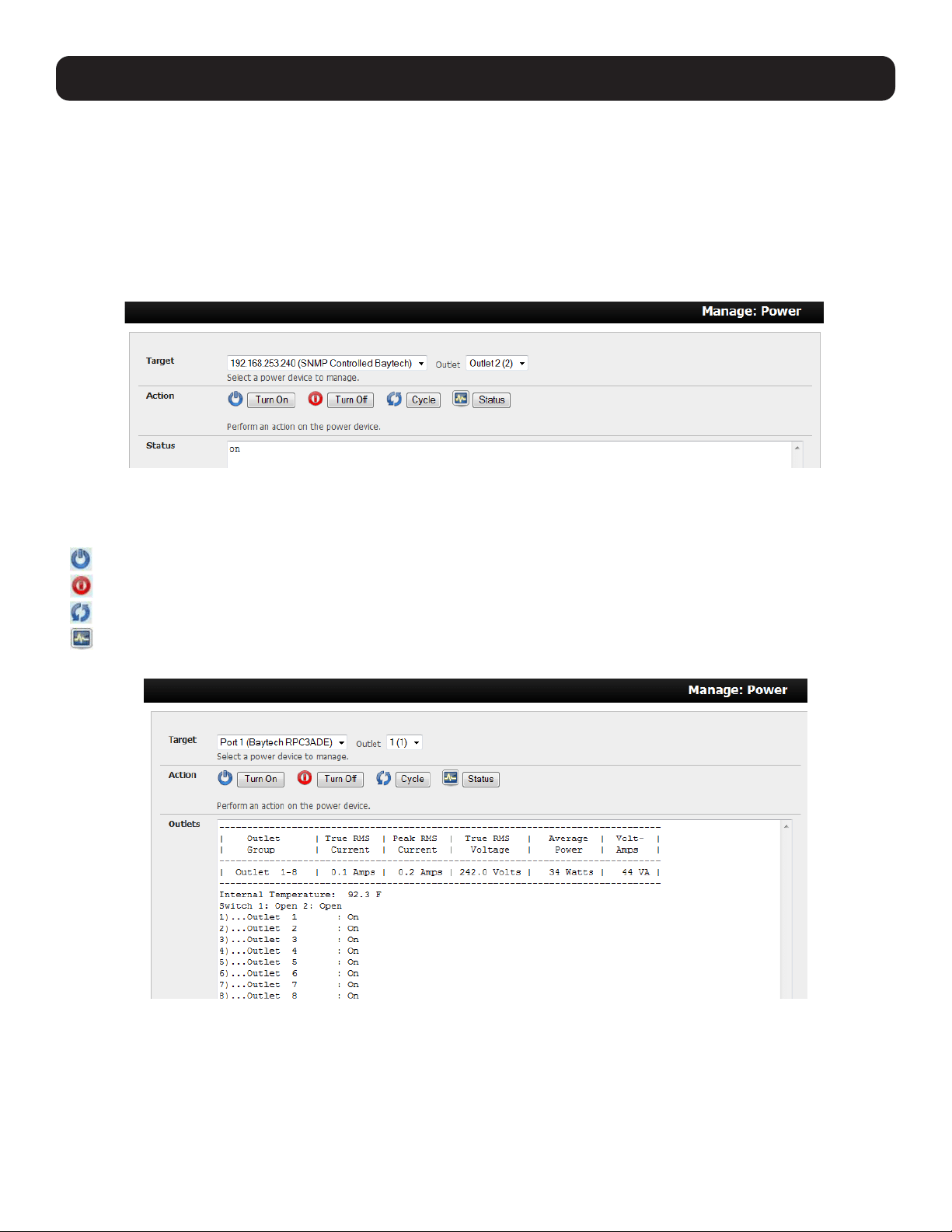
151
8. Power, Environment and Digital I/O
8.1.2 RPC Access, Privileges and Alerts
You can set PDU and IPMI alerts using Alerts & Logging: Alerts (refer to 7. Alerts, Auto-Response and Logging). You can
also assign which user can access and control a particular outlet on each RPC using Serial & Network: User & Groups (refer
to 4. Serial Port, Host, Device and User Configuration).
8.1.3 User Power Management
The power manager enables both users and administrators to access and control the configured serial and network attached
PDU power strips, servers with embedded IPMI service processors or BMCs:
• Select Manage: Power, the particular Target power device to be controlled and the outlet to be controlled (if the RPC
supports outlet level control).
• The outlet status is displayed. You can initiate the desired Action to be taken by selecting the appropriate icon:
Turn ON
Turn OFF
Cycle
Status
You will only be presented with icons for those operations that are supported by the Target you have selected.
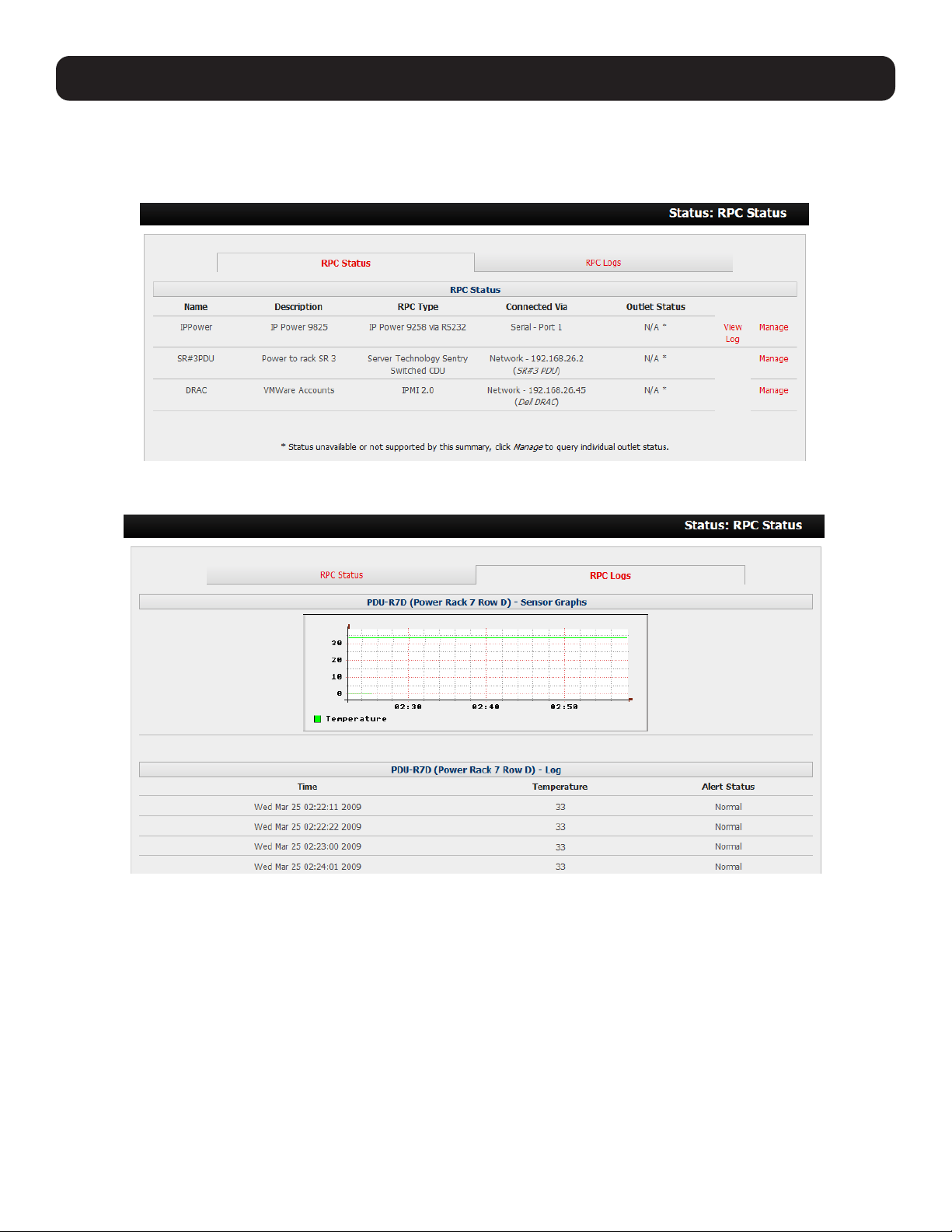
152
8. Power, Environment and Digital I/O
8.1.4 RPC Status
You can monitor the current status of your network and serially connected PDUs and IPMI RPCs.
• Select the Status: RPC Status menu. A table with the summary status of all connected RPC hardware will display.
• Click on View Log or select the RPCLogs menu. You will be presented with a table of the history and detailed graphical
information on the selected RPC.
• Click Manage to query or control the individual power outlet. This will take you to the Manage: Power screen.
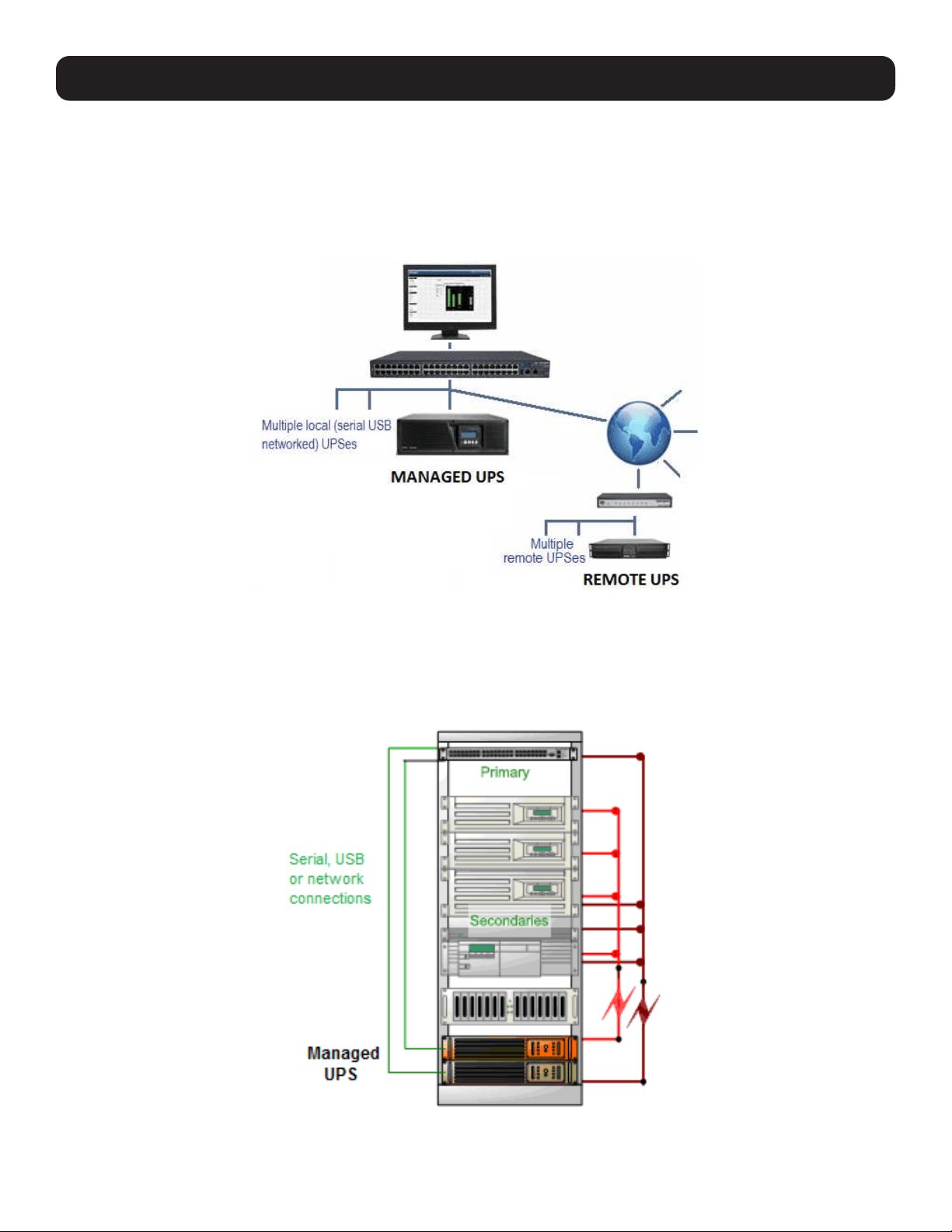
153
8. Power, Environment and Digital I/O
8.2 Uninterruptible Power Supply (UPS) Control
All Tripp Lite console servers can be configured to manage locally and remotely connected UPS hardware using Network UPS
Tools.
Network UPS Tools (NUT) is a group of open source programs that provide a common interface for monitoring and
administering UPS hardware to ensure safe shutdowns of connected systems. NUT is built on a networked model with a
layered scheme of drivers, server and clients (refer to 8.2.6 Overview of Network UPS Tools).
8.2.1 Managed UPS Connections
A managed UPS directly connects as a managed device to the console server. It can be connected by serial cable, USB cable,
or the network. The console server becomes the Primary unit of this UPS and runs a upsd server to allow other computers
that are drawing power through the UPS (Secondary units) to monitor the UPS status and take appropriate action, such as
shutdown in event of low UPS battery.
The console server may or may not be drawing power through the managed UPS. When the UPS battery power reaches a
critical point, the console server will signal and wait for Secondary units to shut down before powering off the UPS.
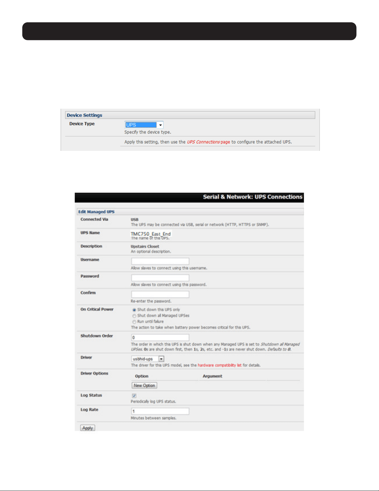
154
8. Power, Environment and Digital I/O
Serial and network-connected UPS systems must first be connected to and configured to communicate with the console
server:
• For serial UPS systems, attach the UPS to the selected serial port on the console server. From the Serial and Network:
Serial Port menu, configure the Common Settings of that port with the RS-232 properties required by the UPS (refer to
4.1.1 Common Settings). Select UPS as the Device Type.
• Similarly, for each network-connected UPS, go to Serial & Network: Network Hosts menu and configure the UPS as a
connected host by specifying it as Device Type: UPS. Click Apply.
• No such configuration is required for USB-connected UPS hardware.
• Select the Serial & Network: UPS Connections menu. The Managed UPS section will display all UPS connections that
have already been configured.
• Click Add Managed UPS.
• Select if the UPS will be Connected Via USB, over preconfigured serial port or SNMP/HTTP/HTTPS over the preconfigured
network host connection.
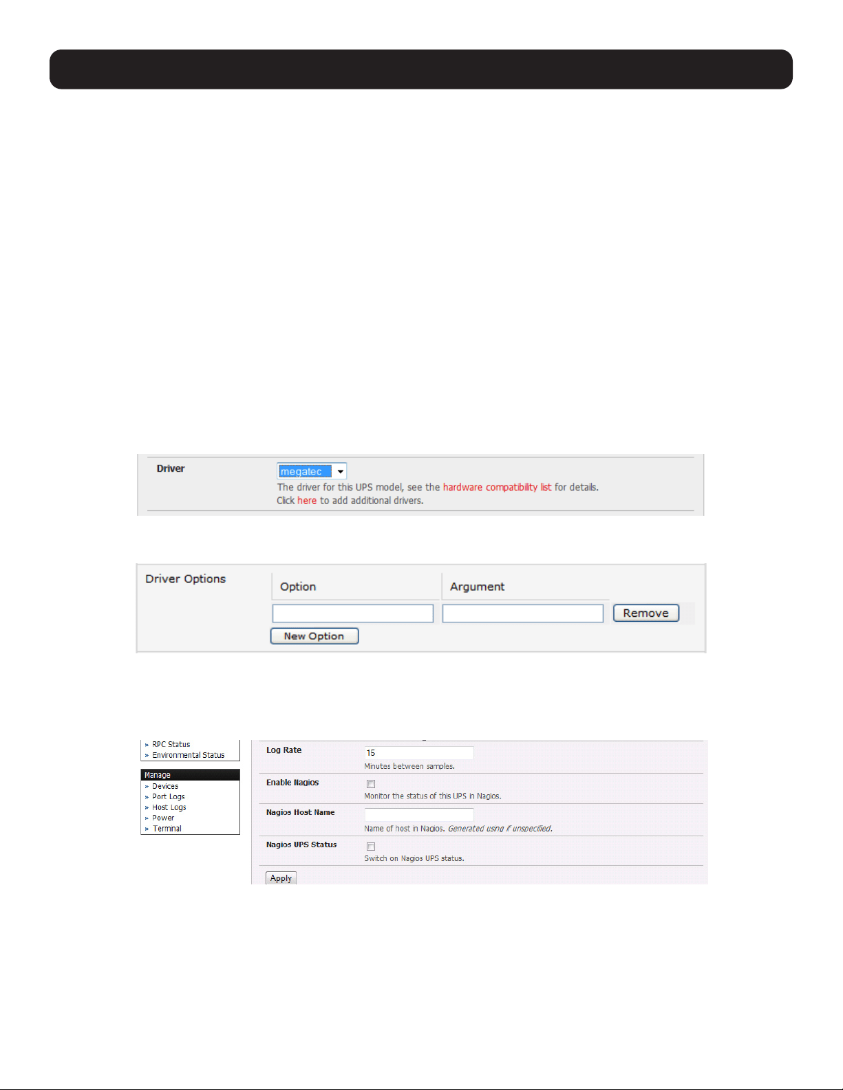
155
8. Power, Environment and Digital I/O
• When you select a network UPS connection, the corresponding host name/description you set up for that connection will
be entered as the Name and Description for the power device. Alternately, if you selected to Connect Via USB or serial
connection, you will need to enter a Name and Description for the power device (these details will also be used to create a
new managed device entry for the serial/USB-connected UPS devices).
• Enter the login details. This Username and Password is used by Secondary units of this UPS (i.e. other computers that are
drawing power through this UPS) to connect to the console server to monitor the UPS status so they can shut themselves
down when battery power is low. Monitoring will typically be performed using the upsmon client running on the Secondary
server (refer to 8.2.3 Controlling UPS Powered Computers).
Note: These login credentials are not related to the users and access privileges configured in Serial & Networks: Users & Groups.
• Select the action to take when UPS battery power becomes critical (i.e. shut down the UPS or shut down all managed UPS
systems) or simply allow the unit(s) to run until failure.
Note: The shutdown script /etc/scripts/ups-shutdown can be customized in the event of a critical power failure (when the UPS battery runs
out). In doing so, you can program the console server to perform final shutdown actions before backup power is lost. However, it is easier
to perform final shutdown actions by triggering auto-response on the UPS. Refer to 7. Alerts, Auto-Response and Logging for more
information.
• If you have multiple UPS systems and require them to be shut down in a specific order, specify the Shutdown Order for
this UPS. This is a whole positive number, or -1. 0s are shut down first, then 1s, 2s, etc. -1s are not shut down at all. The
default setting is 0.
• Select the Driver that will be used to communicate with the UPS.
• Click New Options in Driver Options if you need to set driver-specific options for your selected NUT driver and hardware
combination (more details can be found at http://www.networkupstools.org/doc).
• Check Log Status and specify the Log Rate (minutes between samples) if you wish to have the status from this UPS be
logged. These logs can then be viewed from the Status: UPS Status screen.
• If Nagios services are enabled, you will be presented with an option for Nagios monitoring. Check the Enable Nagios
checkbox to allow the UPS to be monitored using Nagios central management.
• Check Enable Shutdown Script if the UPS is providing power to the console server. In the event of a critical power failure,
you can perform any final shutdown actions on the console server before power is lost. This is done by placing a custom
script in /etc/config/scripts/ups-shutdown (you may use the provided /etc/scripts/ups-shutdown as a template). This
script is only run when the UPS reaches critical battery status.
• Click Apply.
Note: You can also customize the upsmon, upsd and upsc settings for this UPS hardware directly from the command line.
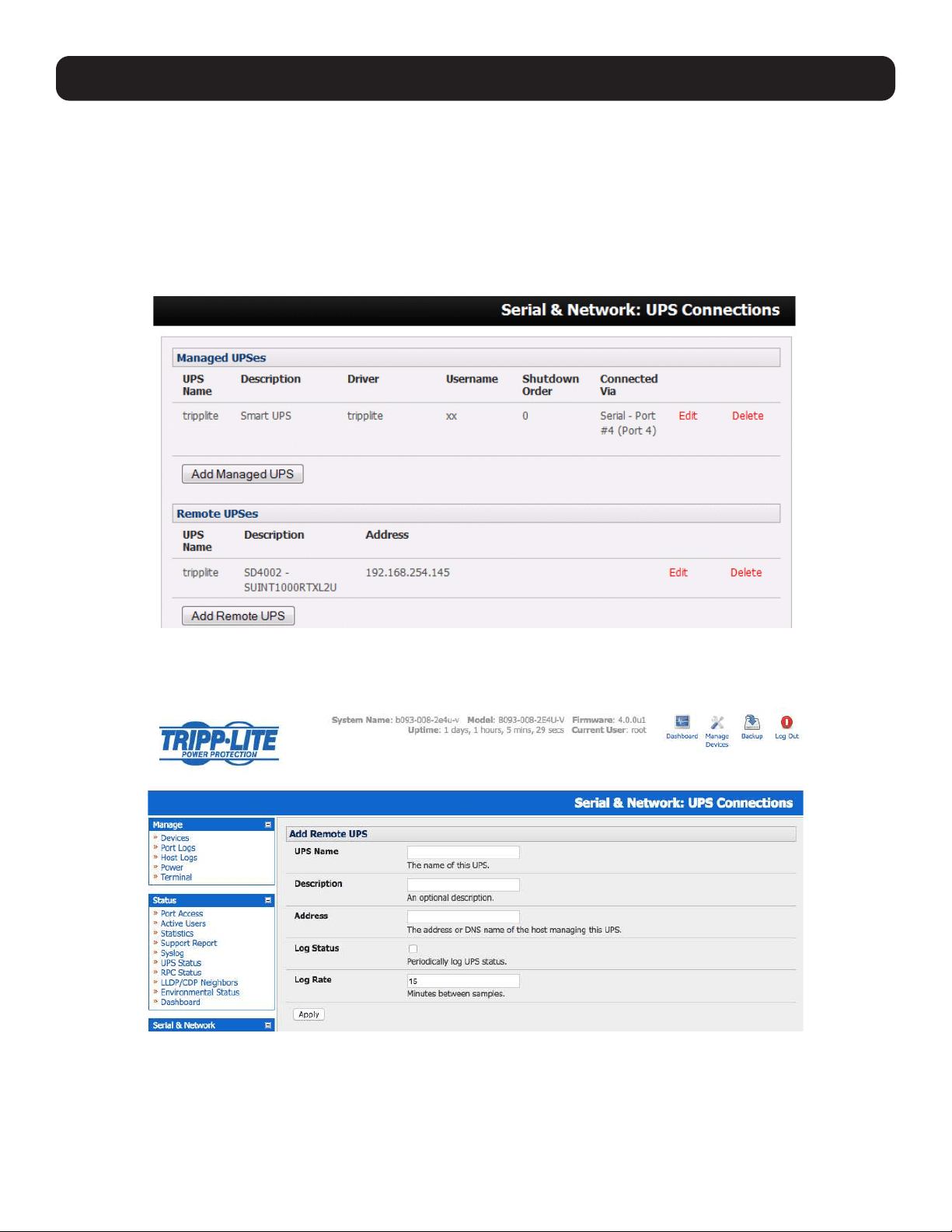
156
8. Power, Environment and Digital I/O
8.2.2 Remote UPS Management
A remote UPS is a managed device connected to a remote console server that is being monitored (but not managed) by your
console server.
The upsc and upslog clients in the Tripp Lite console server can configured to monitor remote servers running Network UPS
Tools that manage their locally connected UPS systems. These remote servers may be other Tripp Lite console servers or
generic Linux servers running NUT. All distributed UPS systems may be spread in a row in a data center, around a campus
property or across the country, and can be centrally monitored through a single central console server window. To add a
remote UPS:
• Select the Serial & Network: UPS Connections menu. The Remote UPS section will display all the remote UPS devices
being monitored.
• Click Add Remote UPS.
• Enter the Name of the particular remote UPS to be remotely monitored. This name must be the name that the remote
UPS was configured to on the remote console server (as the remote console server may have multiple UPS units that it is
managing locally with NUT). Optionally, you may also enter a Description.

157
• Enter the IP Address or DNS name of the remote console server* that is managing the remote UPS. (*This may be another
Tripp Lite console server or it may be a generic Linux server running Network UPS Tools).
Note: An example where centrally monitored and remotely distributed UPS systems are useful is a campus or large business site where a
multitude of computer and other equipment sites are widely spread out and with each containing its own UPS supply. Many of these sites
(particularly the smaller sites) will be USB or serially connected.
Having a console server at these remote sites allows the system manager to centrally monitor the power supply status at all sites and
centralize alarms. In doing so, the system manager can receive warning to initiate a call-out or shut down.
• Check Log Status and specify the Log Rate (minutes between samples) if you wish the status from the UPS to be logged.
These logs can then be viewed from the Status: UPS Status screen.
• Check Enable Shutdown Script if the remote UPS is providing power to the console server. In the event the UPS reaches
critical battery status, the custom script in /etc/config/scripts/ups-shutdown will run, allowing you to perform any final
shutdown actions.
• Click Apply.
Note: The remote UPS feature is supported on all console servers with firmware version 2.8 and later. Earlier versions support a single
remote “Monitored UPS”, which could be set to trigger the console server shutdown script.
8.2.3 Controlling UPS Powered Computers
One advantage of using a managed UPS is you can configure computers that draw power through that UPS to be shut down
gracefully in the event of a prolonged power failure.
For Linux computers, this is accomplished by setting up upsmon on each computer and directing them to monitor the console
server managing their UPS. This will set the specific conditions used to initiate a computer shut down. Non-critical servers may
be powered down seconds after the UPS starts running on battery, whereas servers that are more critical may not shut down
until a low battery warning is received. Refer to the online NUT documentation for details:
http://eu1.networkupstools.org/doc/2.2.0/INSTALL.html
http://linux.die.net/man/5/upsmon.conf
http://linux.die.net/man/8/upsmon
An example upsmon.conf entry may look like:
MONITOR [email protected] 1 username password Secondary
- managedups is the UPS Name of the Managed UPS
- 192.168.0.1 is the IP address of the Tripp Lite console server
- 1 indicates the server has a single power supply attached to this UPS
- username is the Username of the Managed UPS
- password is the Password of the Manager UPS
NUT monitoring clients are available for Windows computers (WinNUT).
If you have an RPC (PDU), it is also possible to shut down UPS-powered computers and other equipment without them having
a client running (e.g., communications and surveillance gear).
8.2.4 UPS Alerts
You can set UPS alerts using Alerts & Logging: Alerts (refer to 7. Alerts, Auto-Repsonse and Logging).
8. Power, Environment and Digital I/O
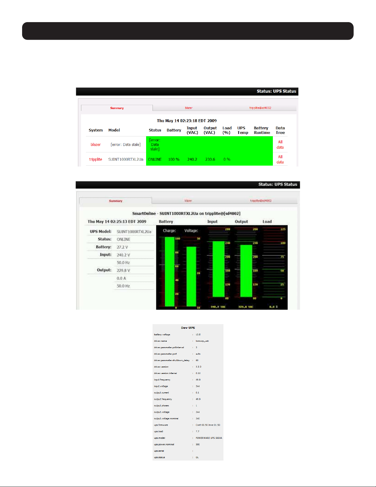
158
8. Power, Environment and Digital I/O
8.2.5 UPS Status
You can monitor the current status of your network, serial or USB-connected managed UPS systems and any configured
remote UPS systems.
• Select the Status: UPS Status menu. A table with the summary status of all connected UPS hardware will display.
• Click on any UPS System name in the table and you will be presented with detailed graphical information.
• Click on All Data for any UPS System in the table for more status and configuration information of a UPS System.
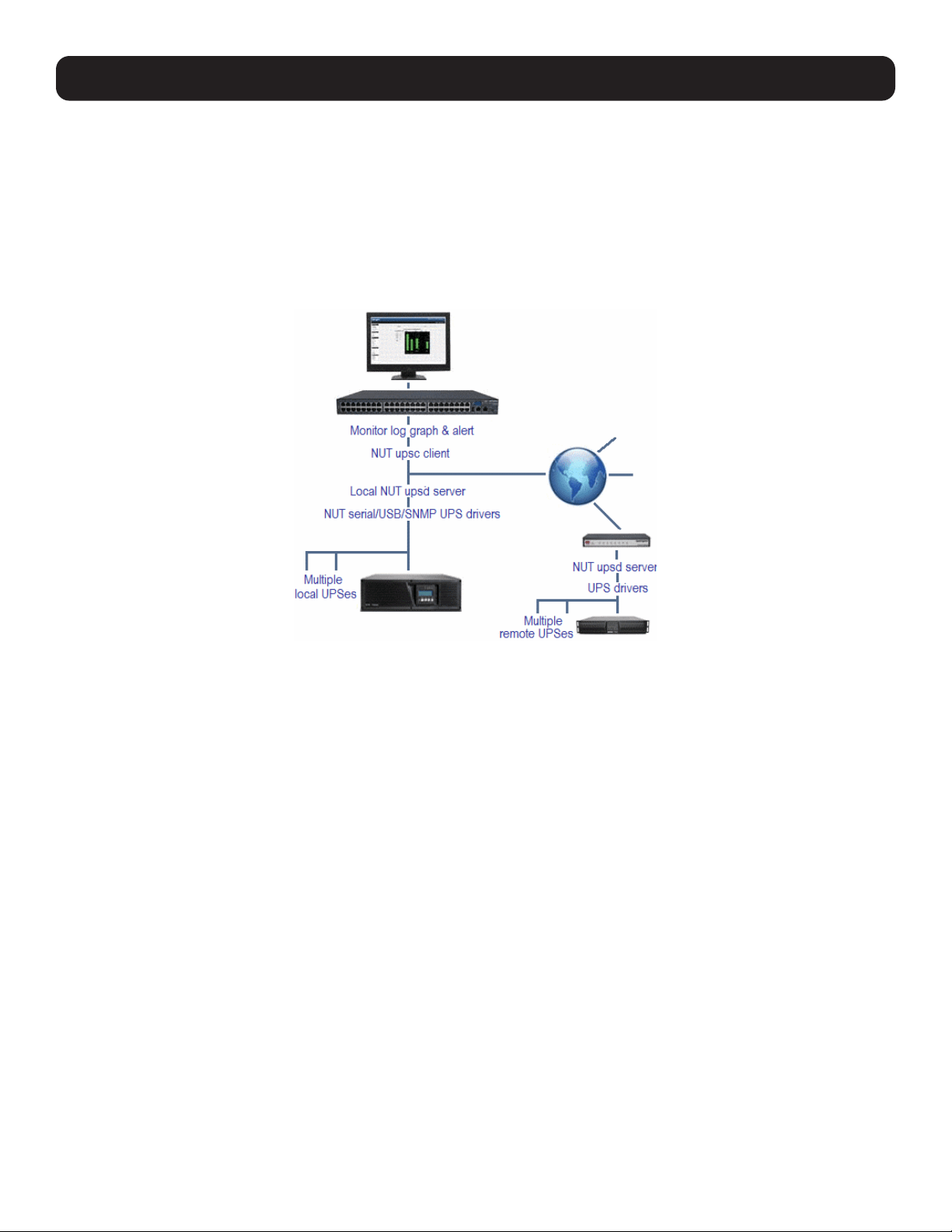
159
• By selecting UPS Logs, you will be presented with the log table of the load, battery charge level, temperature and other
status information from all managed and monitored UPS systems. This information is logged for all UPS systems configured
with the Log Status box checked. The information is also presented graphically.
8.2.6 Overview of Network UPS Tools (NUT)
NUT is built on a networked model with a layered scheme of drivers, server and clients. NUT can be configured using the
management console as described above, or you can configure the tools and manage the UPS systems directly from the
command line. This section provides an overview of NUT. Full documentation is available at http://www.networkupstools.org/
doc.
NUT is built on a networked model with a layered scheme of drivers, server and clients:
• The driver programs communicate directly to the UPS equipment and run on the same host as the NUT network server
(upsd). Drivers are provided for a wide assortment of equipment from most of the popular UPS vendors. They understand
the specific language of each UPS. They communicate to serial, USB and SNMP network-connected UPS hardware and map
the communications back to a compatibility layer. As a result, both a “smart” protocol UPS and a simple “power strip” model
can be handled transparently.
• The NUT network server program upsd is responsible for passing status data from the drivers to the client programs via the
network. upsd can cache the status from multiple UPS systems and then serve this status data to many clients. upsd also
contains access control features to limit the abilities of the clients, so only authorized hosts may monitor or control the UPS
hardware.
• There are a number of NUT clients that connect to upsd to check on the status of the UPS hardware and perform actions
based on the status. These clients can run on the same host as the NUT server or they can communicate with the NUT
server over the network, enabling them to monitor any UPS anywhere:
o The upsc client provides a quick way to poll the status of a UPS server. It can be used inside shell scripts and other
programs that require UPS data but do not want to include the full interface.
o The upsmon client enables servers that draw power through the UPS to shutdown gracefully when the battery power
reaches a critical low point.
o Logging clients (upslog) and third party interface clients (Big Sister, Cacti, Nagios, Windows and more) are also available.
• The latest release of NUT (2.4) also controls PDU systems, either natively using SNMP or through a binding to Powerman
(open source software from Livermore Labs is embedded in Tripp Lite console servers).
8. Power, Environment and Digital I/O
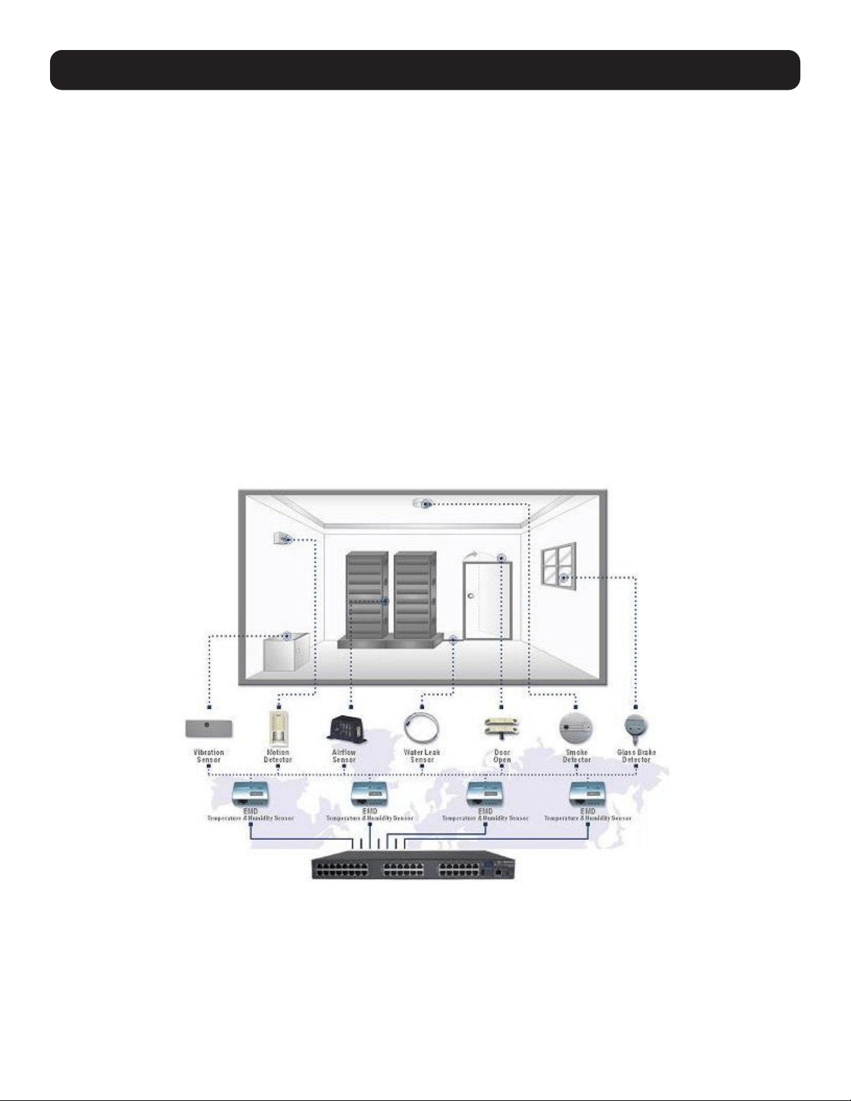
160
8. Power, Environment and Digital I/O
NUT clients and servers all are embedded in each Tripp Lite console server, with a management console presentation layer
added. They also run remotely on distributed console servers and other remote NUT monitoring systems. Layered distributed
NUT architecture enables:
• Multiple manufacturer support: NUT can monitor UPS models from 79 different manufacturers - and PDUs from a growing
number of vendors - with a unified interface.
• Multiple architecture support: NUT can manage serial and USB-connected UPS models with the same common interface.
Network-connected USB and PDU equipment can also be monitored using SNMP.
• Multiple clients monitoring one UPS: Multiple systems may monitor a single UPS using only their network connections.
A wide selection of client programs is available to support monitoring UPS hardware via NUT (Big Sister, Cacti, Nagios and
more).
• Central management of multiple NUT servers: A central NUT client can monitor multiple NUT servers that may be
distributed throughout the data center, across a campus or around the world.
NUT supports complex power architectures found in data centers, communications centers and distributed office environments
where UPS systems from various vendors power systems and clients of all sizes and types.
8.3 Environmental Monitoring
The B090-EMD Environmental Monitoring Device (EMD) can be connected to any Console Server serial port and each Console
Server can support multiple EMDs. Each EMD has one temperature sensor, one humidity sensor and one general-purpose
status sensor that can be connected to a smoke detector, water detector, vibration or open-door sensor.
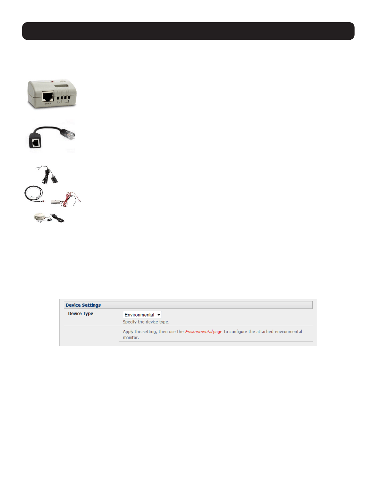
161
8. Power, Environment and Digital I/O
8.3.1 Connecting the EMD and its Sensors
The Environmental Monitor Device (EMD) connects to any serial port on the console server via special EMD Adapter and
standard Cat5 cable. The sensors screw into the EMD.
The EMD is powered over the serial port connection and communicates using a custom handshake
protocol. It is not an RS-232 device and should not be connected without the adapter.
EMD
Plug the EMD adapter’s male RJ connector (model B090-EMD-ADP) into the EMD. Then connect the
adapter to the console server serial port using the provided UTP cable. If the 6 ft. (2 m) UTP cable
provided with the EMD is not long enough, it can be replaced with a standard Cat5 UTP cable up to 33
ft. (10 m) in length (Tripp Lite N002-Series cables).
EMD Adapter
Screw the bare wires on any smoke detector, water detector, vibration sensor, open-door sensor or
general purpose open/close status sensors into the terminals on the EMD.
Screw the bare wires on any smoke detector, water detector, vibration sensor, open-door sensor or
general purpose open/close status sensors into the terminals on the EMD.
B090-WLS – Console Server Water Leak Sensor
B090-DCS – Console Server Door Contact Sensor
B090-VS – Console Server Vibration Sensor
B090-SD-110 – Console Server Smoke Detector – 110V
B090-SD-220 – Console Server Smoke Detector – 120V
EMD sensor
Note: Console servers only support attaching a single sensor to each EMD.
The EMD can only be used with a console server and cannot be connected to standard RS-232 serial ports on other devices.
• Select Environmental as the Device Type in the Serial & Network: Serial Port menu for the port to which the EMD is to
be attached. No particular common settings are required.
• Click Apply.
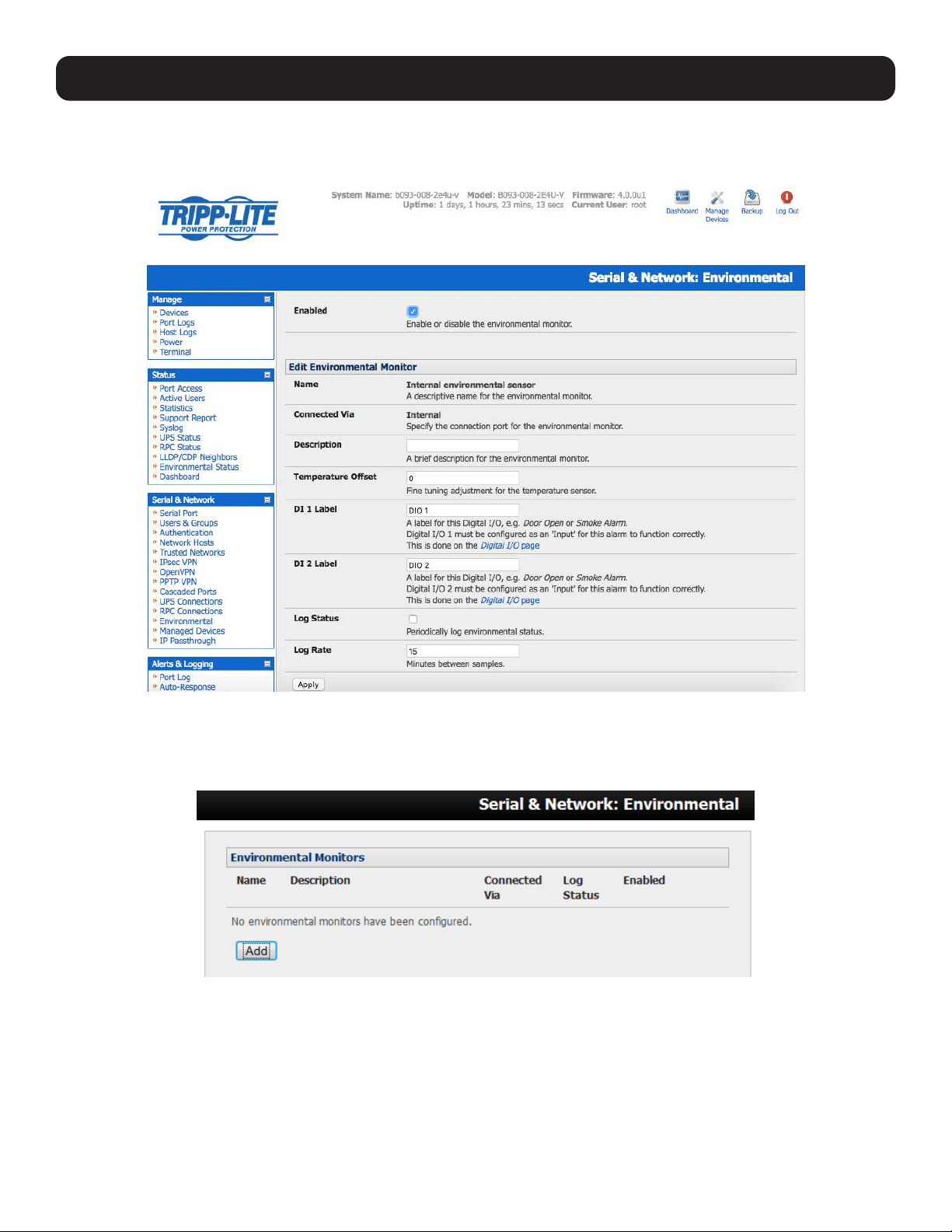
162
8. Power, Environment and Digital I/O
• When configured as Inputs, the SENSOR and DIO ports are notionally attached to the internal EMD. Go to the Serial &
Network: Environmental page and enable the Internal EMD. Then configure the attached sensors as alarms, as covered
in the next section.
8.3.2 Adding EMDs and Configuring the Sensors
• Select the Serial & Network: Environmental menu. This will display any external EMDs or any “internal EMD” (i.e. sensors
that may be directly attached to the unit) that have already been configured.
• To add a new EMD, click Add and configure an external EMD. Enter a Name and (optionally) a Description. Select the
preconfigured serial port the EMD will be Connected Via.
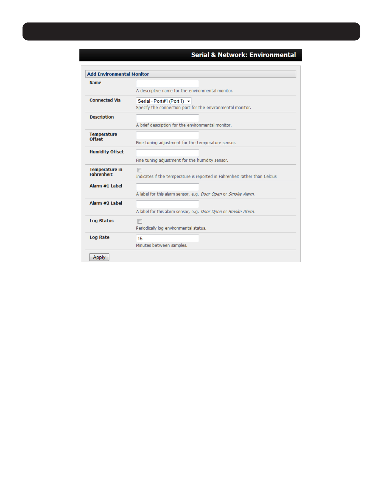
163
• You may optionally calibrate the EMD with a Temperature Offset (+ or - °C) or Humidity Offset (+ or percent). If you check
Temperature in Fahrenheit, the temperature will be reported in Fahrenheit. Otherwise, it will be reported in degrees
Celsius.
• Provide Labels for each of the alarm sensors that will be used (e.g., door open or smoke alarm).
• Check Log Status and specify the Log Rate (minutes between samples) if you wish the status from this EMD to be logged.
These logs can be views from the Status: Environmental Status screen.
• Click Apply. This will also create a new managed device with the same name.
8.3.3 Environmental Alerts
Set temperature, humidity and probe status alerts using Alerts & Logging: Alerts (refer to 7. Alerts, Auto-Response and
Logging for more information.)
8. Power, Environment and Digital I/O
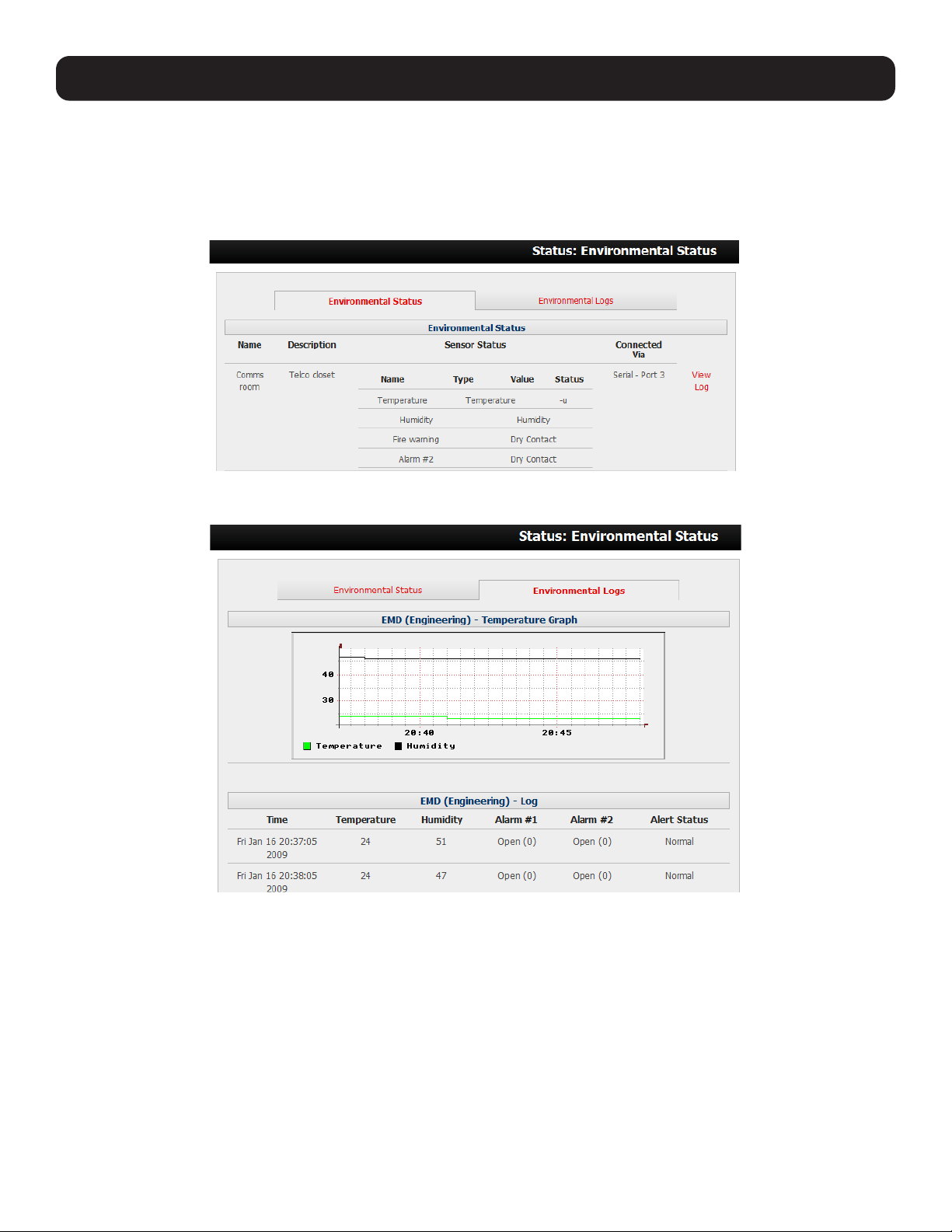
164
8. Power, Environment and Digital I/O
8.3.4 Environmental Status
You can monitor the current status of all configured external EMDs and their sensors, as well as any internal or directly
attached sensors.
• Select the Status: Environmental Status menu. A table with the summary status of all connected EMD hardware will
display.
• Click on View Log or select the Environmental Logs menu. You will be presented with a table and graphical plot of the log
history of the select EMD.
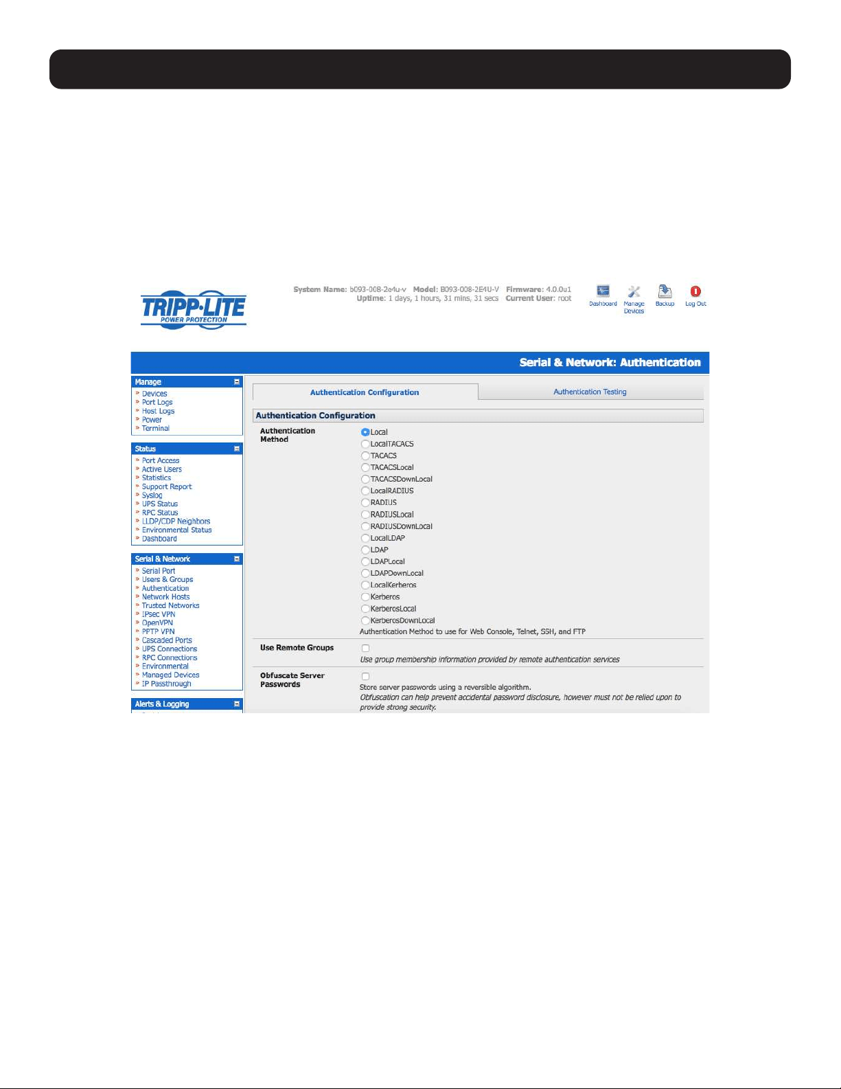
165
9. Authentication
The console server platform is a dedicated Linux computer and embodies myriad popular and proven Linux software modules
for networking, secure access (OpenSSH), communications (OpenSSL) and sophisticated user authentication (PAM, RADIUS,
TACACS+, Kerberos and LDAP).
More details on RSA SecurID and working with Windows IAS can be found on online FAQs.
9.1 Authentication Configuration
Authentication can be performed locally or remotely using an LDAP, Radius, Kerberos or TACACS+ authentication server. The
default authentication method for the console server is Local.
Any authentication method that is configured will be used for authentication of any user who attempts to log in through telnet,
SSH or the web manager to the console server, connected serial port and network host devices.
The console server can be configured to the default (Local) or an alternate authentication method (TACACS, RADIUS, LDAP
or Kerberos) with the option of a selected order in which local and remote authentication is used:
Local TACACS /RADIUS/LDAP/Kerberos: Tries local authentication first, then remote if local fails.
TACACS /RADIUS/LDAP/Kerberos Local: Tries remote authentication first, the local if remote fails.
TACACS /RADIUS/LDAP/Kerberos Down Local: Tries remote authentication first, then local if the remote authentication
returns an error condition (e.g., the remote authentication server is down or inaccessible).
9.1.1 Local Authentication
• Select Serial and Network > Authentication. Check Local.
• Click Apply.
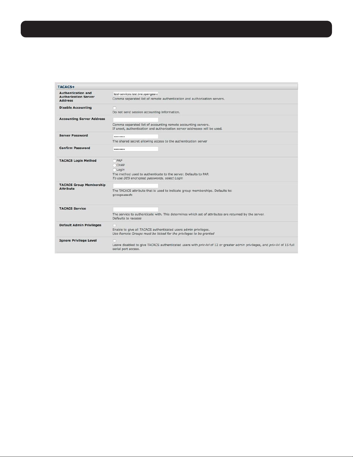
166
9. Authentication
9.1.2 TACACS Authentication
Perform the following procedure to configure the TACACS+ authentication method used whenever the console server or any of
its serial ports or hosts is accessed:
• Select Serial and Network > Authentication and check TACAS, LocalTACACS, TACACSLocal or TACACSDownLocal.
• Enter the Server Address (IP or host name) of the remote authentication/authorization server. Multiple remote servers may
be specified in a comma-separated list. Each server is tried in succession.
• Session accounting is on by default. If session accounting information is not desired, check the Disable Accounting
checkbox. One reason often cited for not wanting session accounting is, if the authentication server does not respond to
accounting requests, the said request may introduce a delay when logging in.
• In addition to multiple remote servers, you can also enter separate lists of authentication/authorization servers and
accounting servers. If no Accounting servers are specified, the authentication/authorization servers are used.
• Enter and confirm the Server Password. Then select the method to be used to authenticate to the server (defaults to PAP).
To use DES encrypted passwords, select Login.
• If required, enter the TACACS Group Membership Attribute to be used to indicate group memberships (defaults to
groupname#n).
• If required, specify the TACACS Service used to authenticate. This determines which set of attributes are returned by the
server (defaults to raccess).
• If required, check Default Admin Privileges to give all TACAS+ authenticated users administrator privileges. Use Remote
Groups must also be checked for these privileges to be granted.
• The TACACS Privilege Level feature only applies to TACACS remote authentication. When Ignore Privilege Level is
enabled, the priv-lvl setting for all of the users defined on the TACACS AAA server will be ignored.
Note: A Tripp Lite device normally interprets a user with a TACACS priv-lvl of 12 or above as an administrator. There is a special case where
a user with a priv-lvl of 15 is also given access to all configured serial ports. When the Ignore Privilege Level option is enabled (checked in
the UI), there are no escalations of privileges based on the priv-lvl value from the TACACS server.
If the only thing configured for one or more TACACS users is priv-lvl (e.g., no specific port access or group memberships set), console
server access will be revoked for those users, as they will not be a member of any groups, even if the Retrieve Remote groups option in the
Authentication menu is enabled.
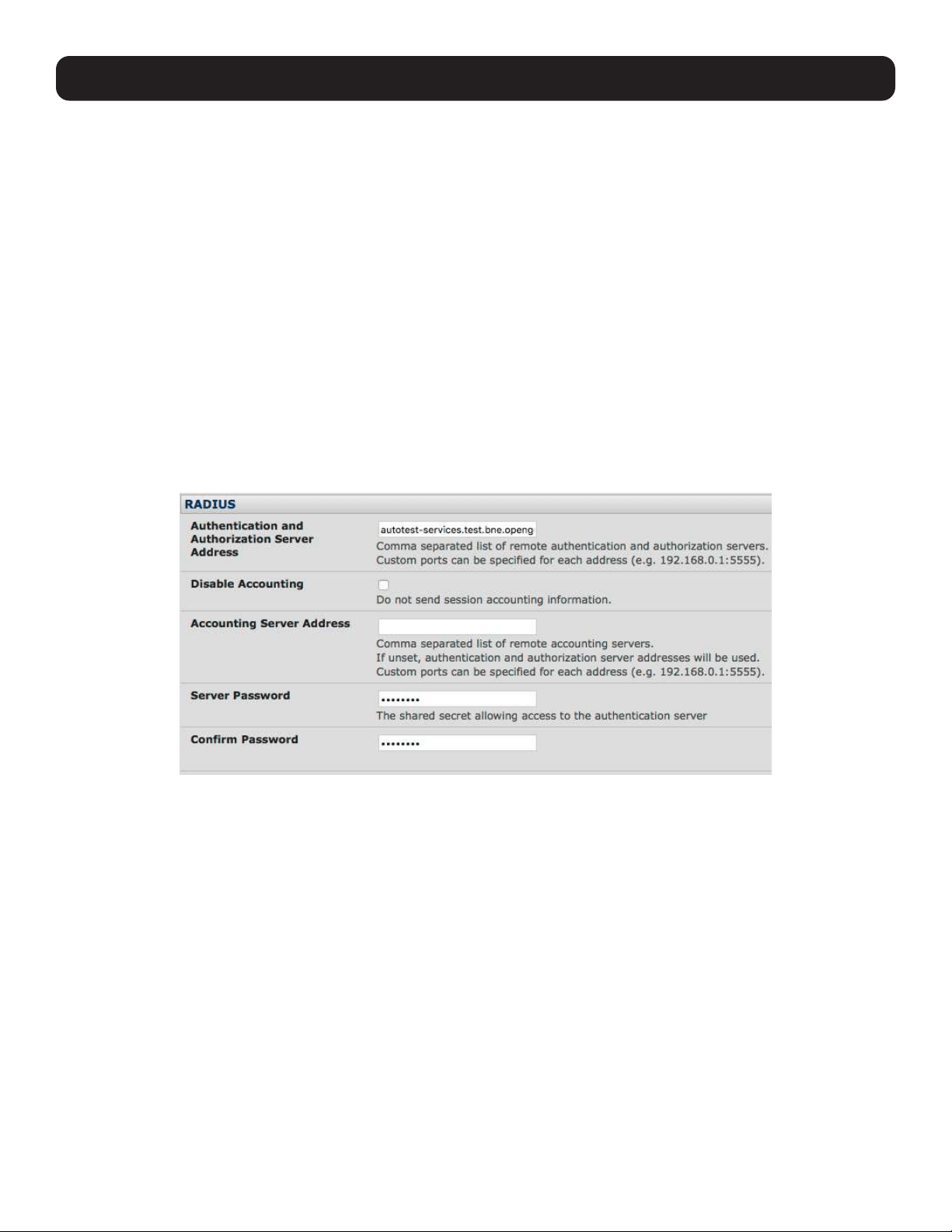
167
• Click Apply. TACAS+ remote authentication will be used for all user access to the console server and serially or network
attached devices
TACACS+ The Terminal Access Controller Access Control System (TACACS+) security protocol is a recent protocol
developed by Cisco. It provides detailed accounting information and flexible administrative control over
authentication and authorization processes. TACACS+ allows a single access control server (the TACACS+
daemon) to provide authentication, authorization and accounting services independently. Each service can be
tied into its own database to take advantage of other services available on that server or network, depending on
the capabilities of the daemon. There is a draft RFC detailing this protocol. Further information on configuring
remote TACACS+ servers can be found at the following websites:
http://www.cisco.com/en/US/tech/tk59/technologies_tech_note09186a0080094e99.shtml
http://www.cisco.com/en/US/products/sw/secursw/ps4911/products_user_guide_chapter09186a00800eb6d6.html
http://cio.cisco.com/univercd/cc/td/doc/product/software/ios113ed/113ed_cr/secur_c/scprt2/sctplus.htm
9.1.3 RADIUS Authentication
Perform the following procedure to configure the RADIUS authentication method used whenever the console server or any of
its serial ports or hosts are accessed:
• Select Serial and Network: Authentication. Check RADIUS, LocalRADIUS, RADIUSLocal or RADIUSDownLocal.
• Enter the Server Address (IP or host name) of the remote authentication/authorization server. Multiple remote servers may
be specified in a comma-separated list. Each server is tried in succession.
• Session accounting is on by default. If session accounting information is not desired, check the Disable Accounting
checkbox. One reason often cited for not wanting session accounting is, if the authentication server does not respond to
accounting requests, the said request may introduce a delay when logging in.
• In addition to multiple remote servers, you can also enter separate lists of authentication/authorization servers and
accounting servers. If no accounting servers are specified, the authentication/authorization servers are used instead.
• Enter the Server Password.
• Click Apply. RADIUS remote authentication will now be used for all user access to console server and serially or network
attached devices.
9. Authentication

168
9. Authentication
RADIUS The Remote Authentication Dial-In User Service (RADIUS) protocol was developed by Livingston Enterprises as
an access server authentication and accounting protocol. The RADIUS server can support a variety of methods to
authenticate a user. When provided with the username and original password by the user, it can support PPP, PAP
or CHAP, UNIX login and other authentication mechanisms. Further information on configuring remote RADIUS
servers can be found at the following websites:
http://www.microsoft.com/technet/prodtechnol/windowsserver2003/library/DepKit/d4fe8248-eecd-49e4-88f6-
9e304f97fefc.mspx
http://www.cisco.com/en/US/tech/tk59/technologies_tech_note09186a00800945cc.shtml
http://www.freeradius.org/
9.1.4 LDAP Authentication
With firmware version 3.11 and later, LDAP authentication now supports OpenLDAP servers using the Posix style schema for
user and group definitions.
Performing simple authentication against any LDAP server (AD or OpenLDAP) is straightforward, as both follow common LDAP
standards and protocols. More difficult is configuring how to obtain extra data about the users, such as groups they are in, etc.
On a Tripp Lite device, it may be configured to analyze group information from an LDAP server for authentication and
authorization. This group information is stored in a number of different ways. Active Directory has one method, and OpenLDAP
has two other methods:
• Active Directory: Each user entry will have multiple ‘memberOf’ attributes. Each ‘memberOf’ value is the full DN of the
group they belong to. The entry for the user will be of objectClass “user”.
• OpenLDAP / Posix: Each entry for a user must have a ‘gidNumber’ attribute. This will be an integer value, which is the
user’s primary group (e.g., mapping to the /etc/passwd file with the group ID field). To determine which group this is,
search for an entry in the directory that has that group ID, which will provide the group name. The users are of objectClass
“posixAccount”, and the groups are of objectClass “posixGroup”.
• OpenLDAP / Posix: Each group entry in the group tree (of objectClass ‘posixGroup’) may have multiple ‘memberUid’
attributes. These represent secondary groups (e.g,, mapping to the /etc/groups file). Each attribute contains a username.
To accommodate all possibilities, the pam_ldap module has been modified to perform group searches for each of the three
styles. This allows for a relatively ‘generic’ configuration and not be concerned with how the LDAP directory is set up.
Only two parameters need to be configured based on what the user wishes to look up: these are the LDAP username and
group membership attributes.
To clarify to the user what parameters to use, the descriptions for these fields are updated to prompt the user for common or
likely attributes. For example, two configuration fields have descriptions as follows:
LDAP Username Attribute: Corresponds to the login name of the user (commonly ‘sAMAccountName’ for Active Directory,
and ‘uid’ for OpenLDAP).
LDAP Group Membership Attribute: Indicates group membership in a user record (commonly ‘memberOf’ for Active
Directory, and unused for OpenLDAP).
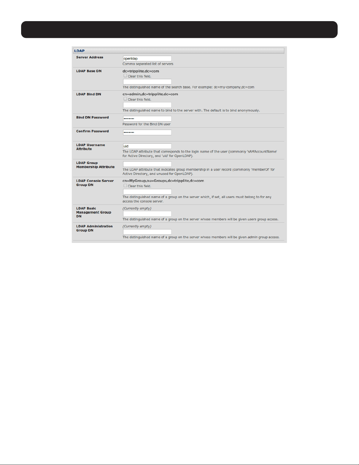
169
Note: The libldap library is particular about ensuring SSL connections are using certificates signed by a trusted CA. As such, it is often not
easy to set up a connection to an LDAP server using SSL.
Perform the following procedure to configure the LDAP authentication method used whenever the console server or any of its
serial ports or hosts are accessed:
• Select Serial and Network: Authentication and check LDAP or LocalLDAP or LDAPLocal or LDAPDownLocal.
9. Authentication
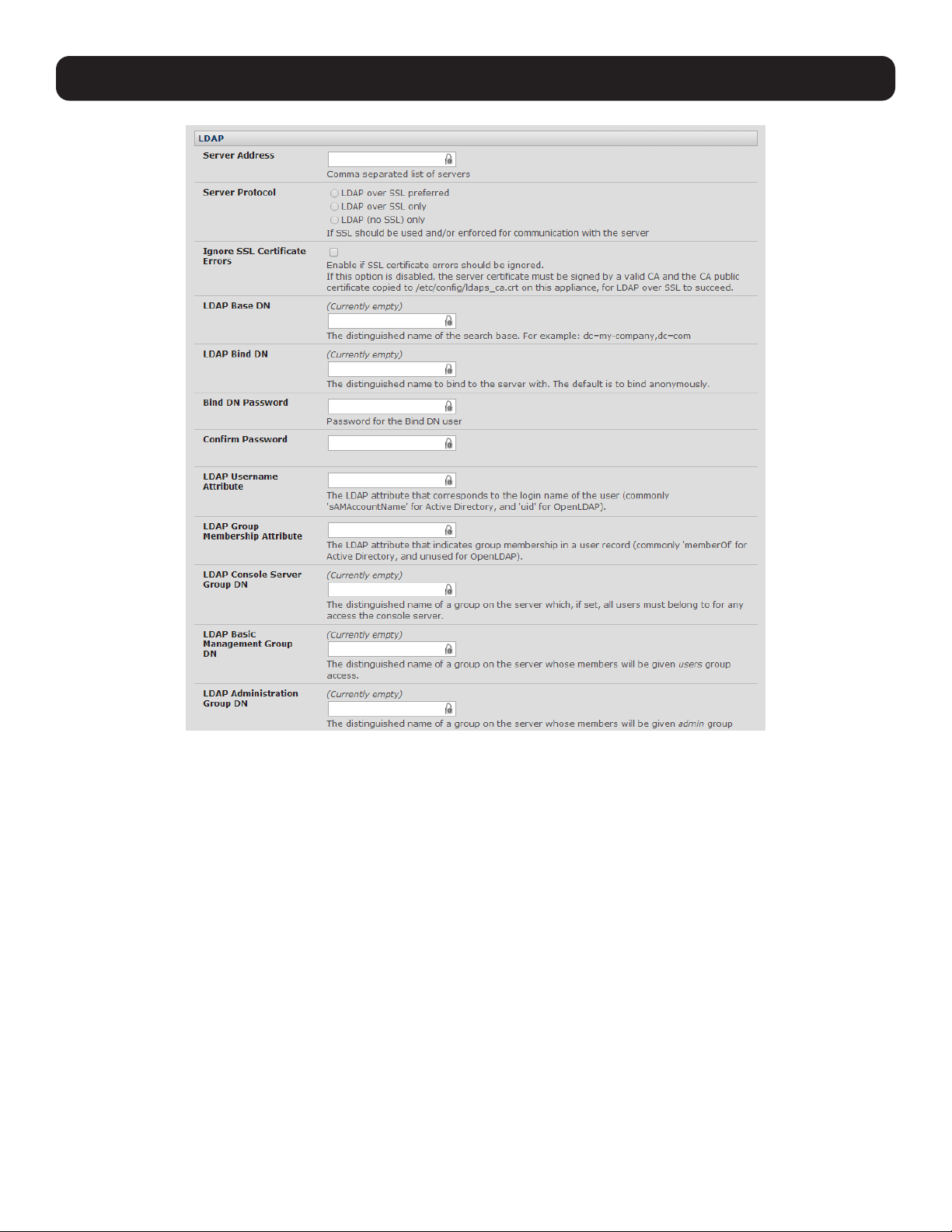
170
9. Authentication
• Enter the Server Address (IP or host name) of the remote authentication server. Multiple remote servers may be specified
in a comma-separated list. Each server is tried in succession.
• Check the Server Protocol box to select if SSL is to be used and/or enforced for communications with the LDAP server.
Console servers running firmware version 3.11 and above offer three options for LDAPS (LDAP over SSL):
o LDAP over SSL preferred: will attempt to use SSL for authentication. If it fails, it will default to LDAP without SSL. For
example, LDAP over SSL may fail due to certificate errors or the LDAP server cannot be contacted on the LDAPS port.
o LDAP over SSL only: will configure the Tripp Lite device to only accept LDAP over SSL. If LDAP over SSL fails, you will
only be able to log into the console server as root.
o LDAP (no SSL) only: will configure the Tripp Lite device to only accept LDAP without SSL. If LDAP without SSL fails, you
will only be able to log into the console server as root.
• The Ignore SSL Certificate Error checkbox enables you to ignore SSL certificate errors, in effect allowing LDAP over SSL
to work, regardless of these errors. You can use any certificate, self-signed or otherwise, on the LDAP server without having
to install any certificates on the console server. If this setting is not checked, you must install the CA (certificate authority)
certificate with which the LDAP server’s certificate was signed onto the console server. For example, the LDAP server
provides a certificate signed myCA.crt.
Note: The certificate needs to be in CRT format and myCA.crt needs to be installed on console server at /etc/config/ldaps_ca.crt. Also, the
file name must be ldaps_ca.crt. You will need to copy the file to this location and manually name using ‘scp’ or the like. Some examples
include:
scp /local/path/to/myCA.c
rt root@console_server:/etc/config/ldaps_ca.crt

171
• Enter the Server Password.
• Click Apply. LDAP remote authentication will now be used for all user access to the console server and serially or network
attached devices.
LDAP The Lightweight Directory Access Protocol (LDAP) is based on the X.500 standard, but is significantly simpler and
more readily adapted to meet custom needs. The core LDAP specifications are all defined in RFCs. LDAP is a
protocol used to access information stored in an LDAP server. Further information on configuring remote RADIUS
servers can be found at the following websites:
http://www.ldapman.org/articles/intro_to_ldap.html
http://www.ldapman.org/servers.html
http://www.linuxplanet.com/linuxplanet/tutorials/5050/1/
http://www.linuxplanet.com/linuxplanet/tutorials/5074/4/
9.1.5 RADIUS/TACACS User Configuration
Users may be added to the local console server. If they are not added and they log in via remote AAA, a user will be added
for them. This user will not show up in the Tripp Lite configurators unless they are specifically added, at which point they are
transformed into a local user. The newly added user must authenticate using the remote AAA server and will have no access if
it is down.
If a local user logs in, they may be authenticated/authorized from the remote AAA server, depending on the chosen priority of
the remote AAA. A local user’s authorization is the union of local and remote privileges.
Example 1:
User Tim is locally added and has access to ports 1 and 2. He is also defined on a remote TACACS server, which says he has
access to ports 3 and 4. Tim may log in with either his local or TACACS password, and will have access to ports 1 through 4.
If TACACS is down, he will need to use his local password, and will only be able to access ports 1 and 2.
Example 2:
User Sue is only defined on the TACACS server, which says she has access to ports 5 and 6. When she attempts to log in, a
new user will be created for her and she will be able to access ports 5 and 6. If the TACACS server is down, she will have no
access.
Example 3:
User Paul is defined on a RADIUS server only. He has access to all serial ports and network hosts.
Example 4:
User Don is locally defined on an appliance using RADIUS for AAA. Even if Don is also defined on the RADIUS server, he will
only have access to those serial ports and network hosts he has been authorized to use on the appliance.
If a “no local AAA” option is selected, the root will still be authenticated locally.
Remote users may be added to the administrator group via RADIUS or TACACS. Users may have a set of authorizations set
on the remote TACACS server. Users automatically added by RADIUS will have authorization for all resources, whereas those
added locally will still need their authorizations specified.
LDAP has not been modified and will still need locally defined users.
Note: To interact with RADIUS, TACACS+ and LDAP with console server firmware pre-2.4.2, you must also set up the user accounts on the
local console server. All resource authorizations must be added to the local appliance. With this release, if remote AAA is selected, it is used
for password checking only. Root is always authenticated locally. Any changes to PAM configurations will be destroyed the next time the
authentication configurator is run.
9. Authentication
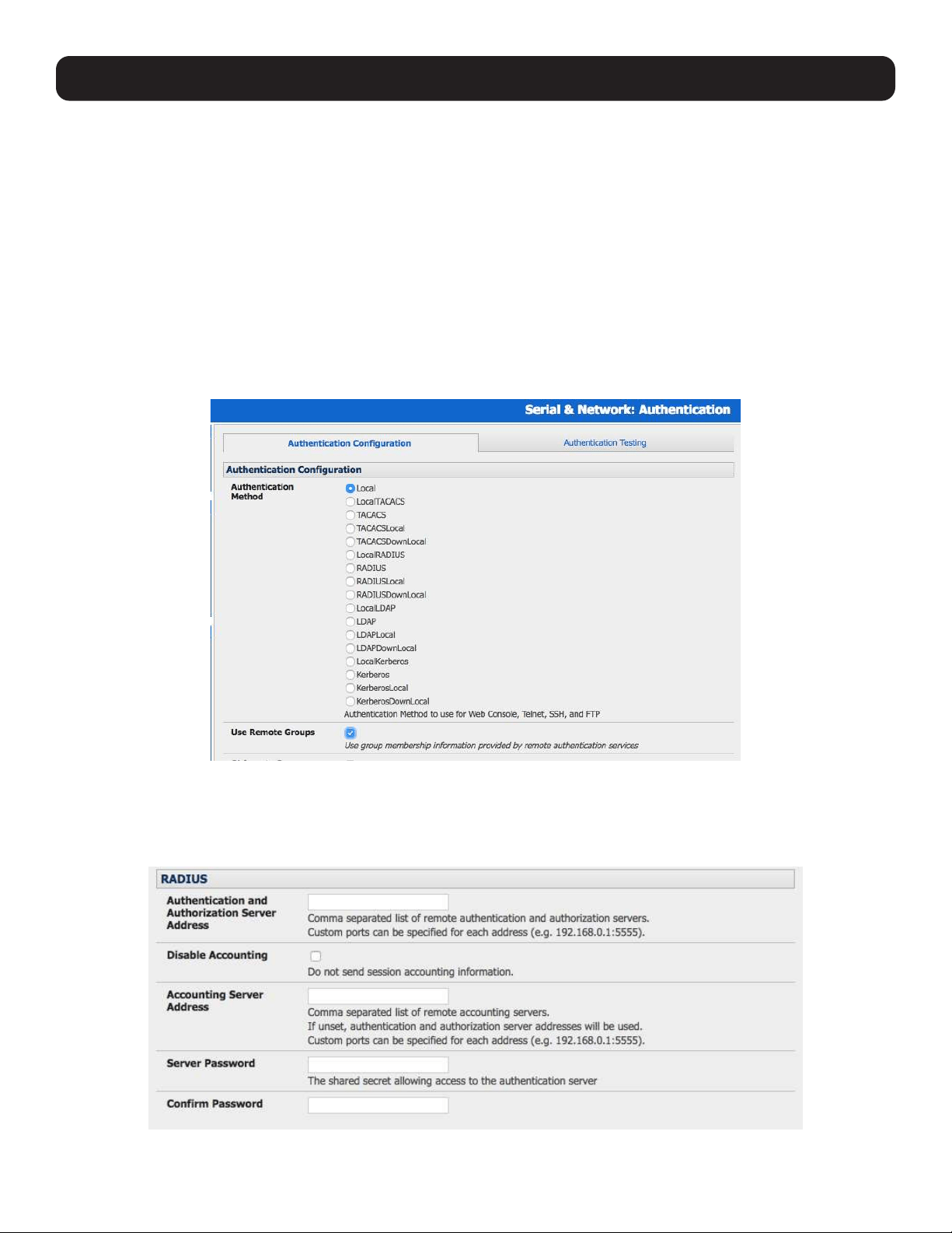
172
9. Authentication
9.1.6 Group Support with Remote Authentication
All console servers allow remote authentication via RADIUS, LDAP and TACACS+. With firmware version 3.2 and later, RADIUS
and LDAP provide additional restrictions on user access based on group information or membership. For example, with remote
group support, users can belong to a local group that has been setup to have restricted access to serial ports, network hosts
and managed devices.
Remote authentication with group support works by matching a local group name with a remote group name provided by
the authentication service. If the list of remote group names returned by the authentication service matches any local group
names, the user is given permissions as configured in the local groups.
To enable group support by remote authentication services:
• Select Serial & Network: Authentication.
• Select the relevant Authentication Method.
• Check the Use Remote Groups button.
9.1.7 Remote Groups with RADIUS Authentication
Enter the RADIUS Authentication and Authorization Server Address and Server Password.
Click Apply.
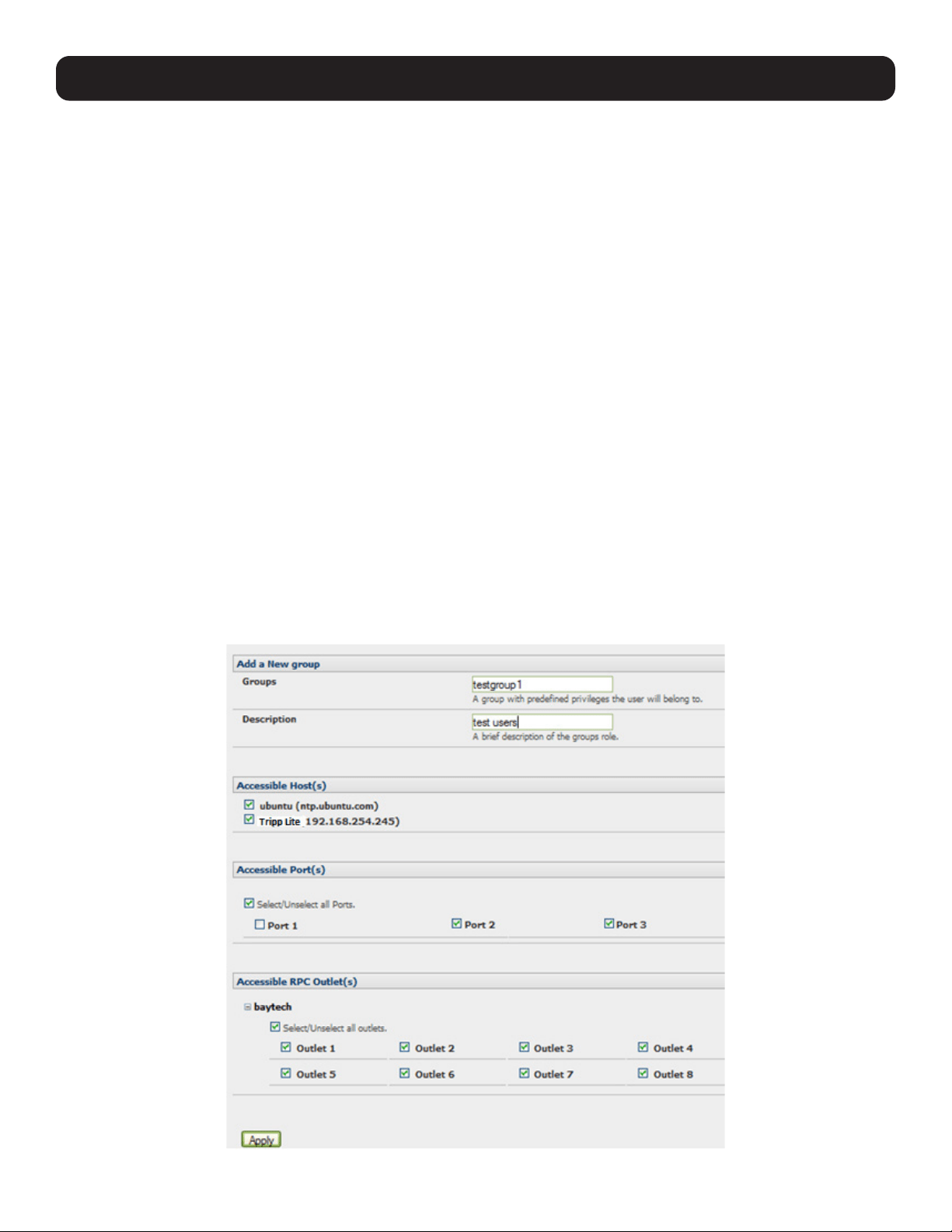
173
9. Authentication
Edit the RADIUS user’s file to include group information and restart the RADIUS server.
When using RADIUS authentication, group names are provided to the console server using the Framed-Filter-Id attribute. This
is a standard RADIUS attribute and may be used by other devices that authenticate via RADIUS.
To interoperate with other devices using this field, the group names can be added to the end of any existing content in the
attribute:
:group_name=testgroup1,users:
The above example sets the remote user as a member of testgroup1 and users if groups with those names exist on the
console server. Any groups that do not exist on the console server are ignored.
When setting the Framed-Filter-Id, the system may also remove the leading colon for an empty field. To work around this, add
some dummy text to the start of the string. For example:
dummy:group_name=testgroup1,users:
• If no group is specified for a user, for example AmandaJones, the user will have no user interface and serial port access, but
limited console access.
• Default groups available on the console server include admin for administrator access and users for general user access.
TomFraser Cleartext-Password := ”FraTom70”
Framed-Filter-Id=”:group_name=admin:”
AmandaJones Cleartext-Password := ”JonAma83”
FredWhite Cleartext-Password := ”WhiFre62”
Framed-Filter-Id=”:group_name=testgroup1,users:”
JanetLong Cleartext-Password := ”LonJan57”
Framed-Filter-Id=”:group_name=admin:”
Additional local groups such as testgroup1 can be added via Users & Groups: Serial & Network.
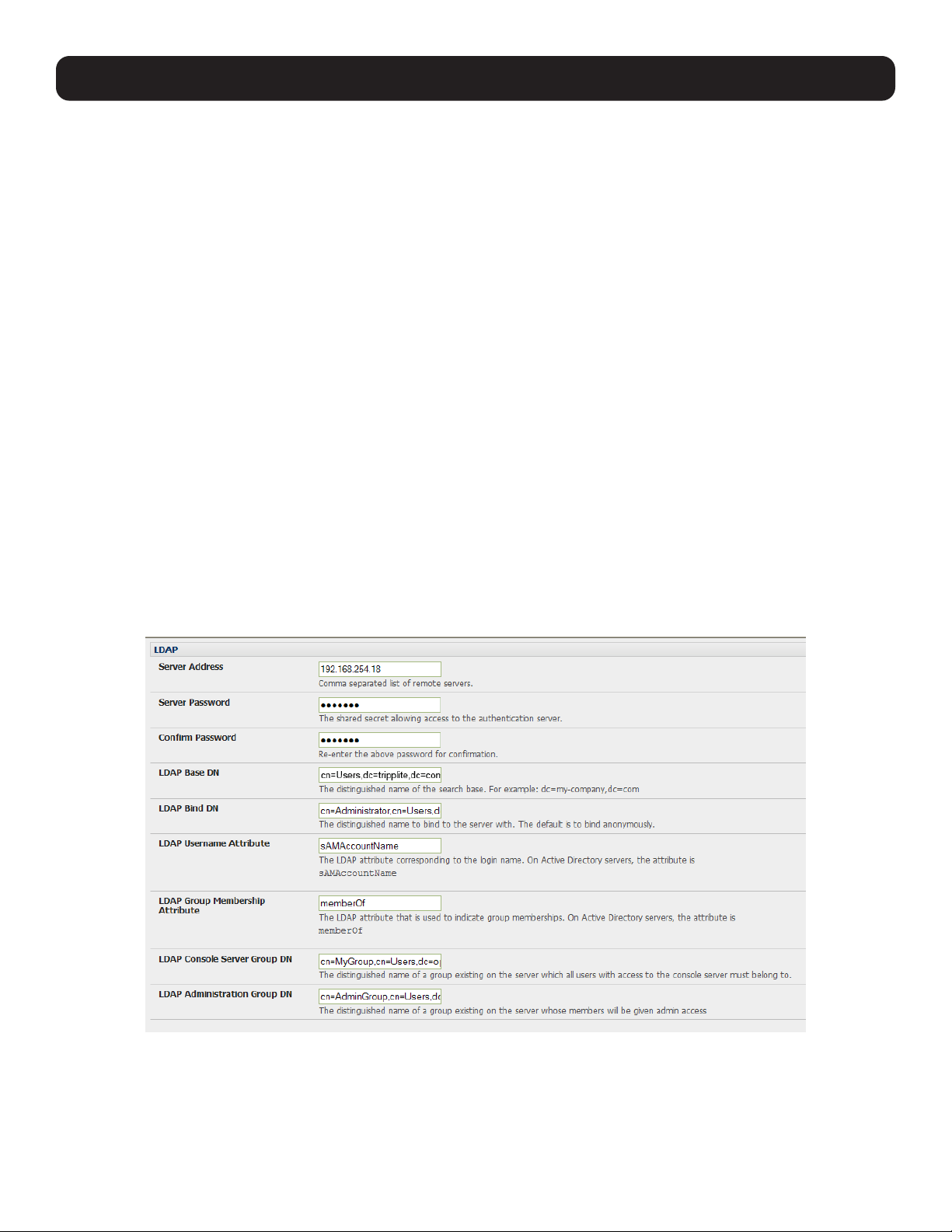
174
9. Authentication
9.1.8 Remote Groups with LDAP Authentication
Unlike RADIUS, LDAP has built-in support for group provisioning, which makes setting up remote groups easier. The console
server will retrieve a list of all the remote groups the user is a direct member of and compare their names with local groups on
the console server.
Note: Any spaces in the group name will be converted to underscores.
For example, in an existing Active Directory setup, a group of users may be part of the UPS Admin and Router Admin
groups. On the console server, these users will be required to have access to a group Router_Admin, with access to port 1
(connected to the router), and another group UPS_Admin, with access to port 2 (connected to the UPS). Once LDAP is set
up, users that are members of each group will have the appropriate permissions to access the router and UPS.
Currently, the only LDAP directory service that supports group provisioning is Microsoft Active Directory. Support is planned for
OpenLDAP later.
To enable group information to be used with an LDAP server:
• Complete the fields for standard LDAP authentication, including LDAP Server Address, Server Password, LDAP Base DN,
LDAP Bind DN and LDAP Username Attribute.
• Enter memberOf for LDAP Group Membership Attribute, as group membership is currently only supported on Active
Directory servers.
• If required, enter the group information for LDAP Console Server Group DN and/or LDAP Administration Group DN.
A user must be a member of the LDAP Console Server Group DN group in order to gain access to the console and user
interface. For example, the user must be a member of “MyGroup” on the Active Server to gain access to the console server.
Additionally, a user must be a member of the LDAP Administration Group DN in order to gain administrator access to the
console server. For example, the user must be a member of “AdminGroup” on the Active Server to receive administration
privileges on the console server.
• Click Apply.
• Ensure the LDAP service is operational and group names are correct within the Active Directory.
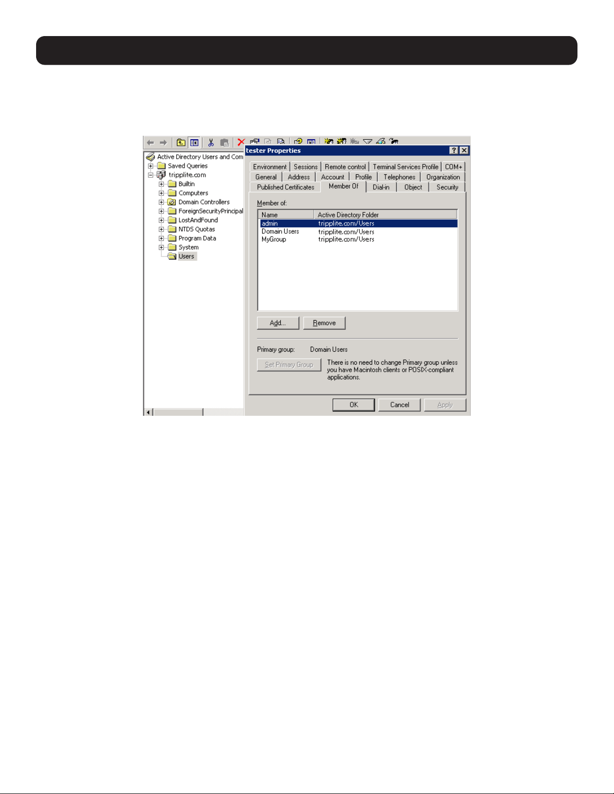
175
Note: When using remote groups with LDAP remote authorization, you need to have corresponding local groups on the console server.
However, where the LDAP group names can contain upper case and space characters, the local group name on the console server must be
all lower case and the spaces replaced with underscores. For example, a remote group on the LDAP server may be My Ldap Access Group
needs a corresponding local group on the console server called my_ldap_access_group (both without the single quotes). The local group
on the console server must specify what the group member is granted access to for any group membership to be effective.
9.1.9 Remote Groups with TACACS+ Authentication
When using TACACS+ authentication, there are two ways to grant a remotely authenticated user privileges. The first is to set
the priv-lvl and port attributes of the raccess service to 12 (refer to 9.2 PAM for more information). Group names can also be
provided to the console server using the groupname custom attribute of the raccess service.
An example Linux tac-plus config snippet might look like:
user = myuser {
service = raccess {
groupname=”users”
groupname1=”routers”
groupname2=”dracs”
}
}
You may also specify multiple groups in one comma-delimited (e.g., groupname=”users,routers,dracs”), but be aware that
the maximum length of the attribute value string is 255 characters.
To use an attribute name other than groupname, set Authentication -> TACACS+ -> TACACS Group Membership
Attribute.
9. Authentication
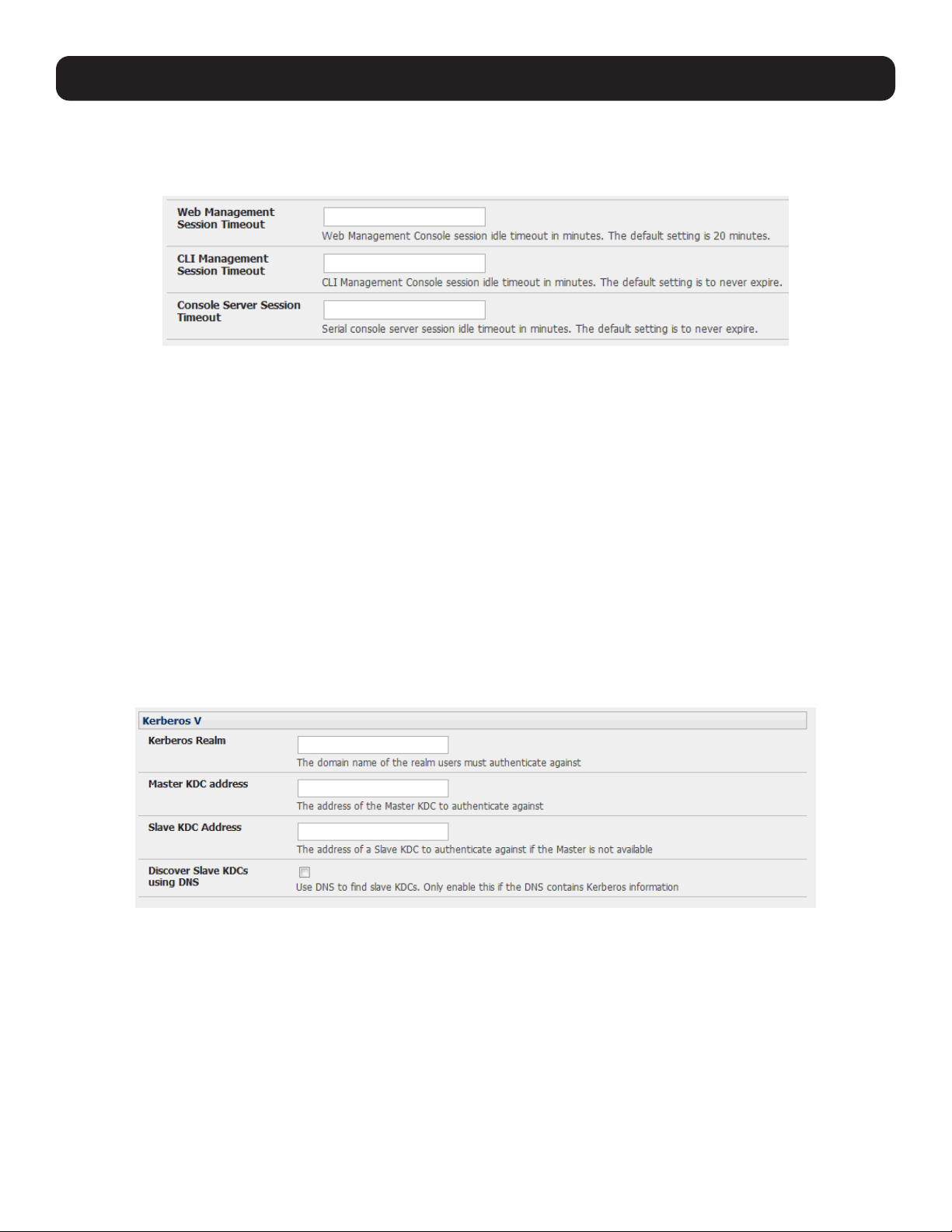
176
9. Authentication
9.1.10 Idle Timeout
You can specify amount of time in minutes the console server waits before it terminates an idle ssh, pmshell or web
connection.
• Select Serial and Network: Authentication.
• Web Management Session Timeout specifies the browser console session idle timeout in minutes. The default setting is
20 minutes.
• CLI Management Session Timeout specifies the ssh console session idle timeout in minutes. The default setting is to
never expire.
• Console Server Session Timeout specifies the pmshell serial console server session idle timeout in minutes. The default
setting is to never expire.
9.1.11 Kerberos Authentication
The Kerberos authentication can be used with UNIX and Windows (Active Directory) Kerberos servers. This form of
authentication does not provide group information, so a local user with the same username must be created and permissions
set.
Note: Kerberos is very sensitive to time differences between the Key Distribution Center (KDC) authentication server and the client device.
Make sure NTP is enabled and the time zone is set correctly on the console server.
When authenticating against Active Directory, the Kerberos Realm will be the domain name and the Primary KDC will be the
address of the primary domain controller.
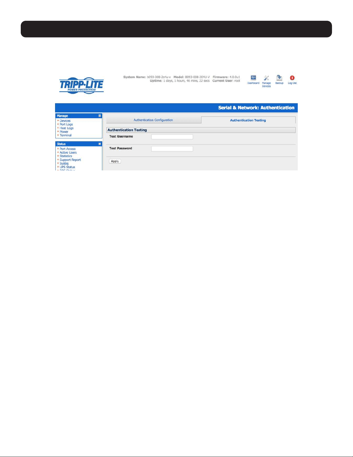
177
9.1.12 Authentication Testing
The Authentication Testing tab (firmware version 3.5.2u3 and later) enables the connection to the remote authentication
server to be tested.
9.2 PAM (Pluggable Authentication Modules)
The console server supports RADIUS, TACACS+ and LDAP for two-factor authentication via PAM (Pluggable Authentication
Modules). PAM is a flexible mechanism for authenticating users. A number of new ways of authenticating users have become
popular. The challenge is that each time a new authentication scheme is developed, it requires all the necessary programs
(login, ftpd, etc.) to be rewritten to support it.
PAM provides a way to develop programs that are independent of authentication scheme. These programs need
“authentication modules” to be attached to them at run-time in order to work. Which authentication module is to be attached
is dependent upon the local system setup and is at the discretion of the local Administrator.
The console server family supports PAM with the following modules added for remote authentication:
RADIUS - pam_radius_auth (http://www.freeradius.org/pam_radius_auth/)
TACACS+ - pam_tacplus (http://echelon.pl/pubs/pam_tacplus.html)
LDAP - pam_ldap (http://www.padl.com/OSS/pam_ldap.html)
Further modules can be added, as required.
Changes may be made to files in /etc/config/pam.d / which will persist, even if the authentication configurator is run.
• Users added on demand:
When a user attempts to log in, but does not already have an account on the console server, a new user account will be
created. This account will have no rights and no password set. They will not appear in the Tripp Lite configuration tools.
Automatically added accounts will not be able to log in if the remote servers are unavailable.
• Administrator rights granted over AAA:
Users may be granted Administrator rights via networked AAA. For TACACS, a priv-lvl of 12 of above indicates an
administrator. For RADIUS, administrators are indicated via Framed Filter ID. See the example configuration files below for
more information.
• Authorization via TACACS, LDAP or RADIUS for using remote groups:
Refer to 9.1.6 Group Support with Remote Authentication.
• Authorization via TACACS for both serial ports and host access:
Permission to access resources may be granted via TACACS by indicating a Tripp Lite device and a port or networked host
the user may access. See the example configuration files below for more information.
9. Authentication
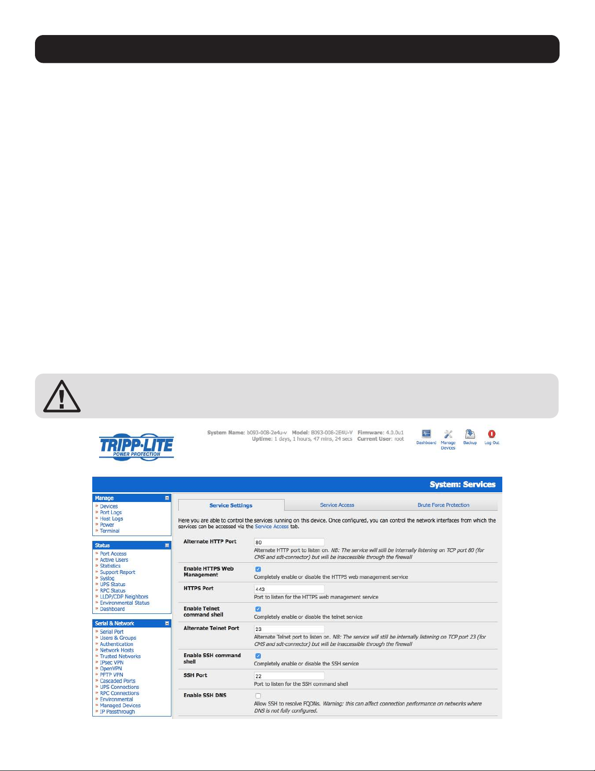
178
9. Authentication
TACACS Example:
user = tim {
service = raccess {
priv-lvl = 11
port1 = b093/port02
}
global = cleartext mit
}
RADIUS Example:
paul Cleartext-Password := “luap”
Service-Type = Framed-User,
Fall-Through = No,
Framed-Filter-Id=”:group_name=admin:”
The list of groups may include any number of entries separated by a comma. If the administrator group is included, the user
will be made an Administrator.
If there is already a Framed-Filter-Id, simply add the list of group_names after the existing entries, including the separating
colon “:”.
9.3 SSL Certificate
The console server uses the Secure Socket Layer (SSL) protocol for encrypted network traffic between itself and a connected
user. While establishing a connection, the console server has to expose its identity to the user’s browser using a cryptographic
certificate. The default certificate that comes with the console server device upon delivery is for testing purposes only and
should not be relied on for secured global access.
The System Administrator should not rely on the default certificate as the secured global access
mechanism for use on the Internet.
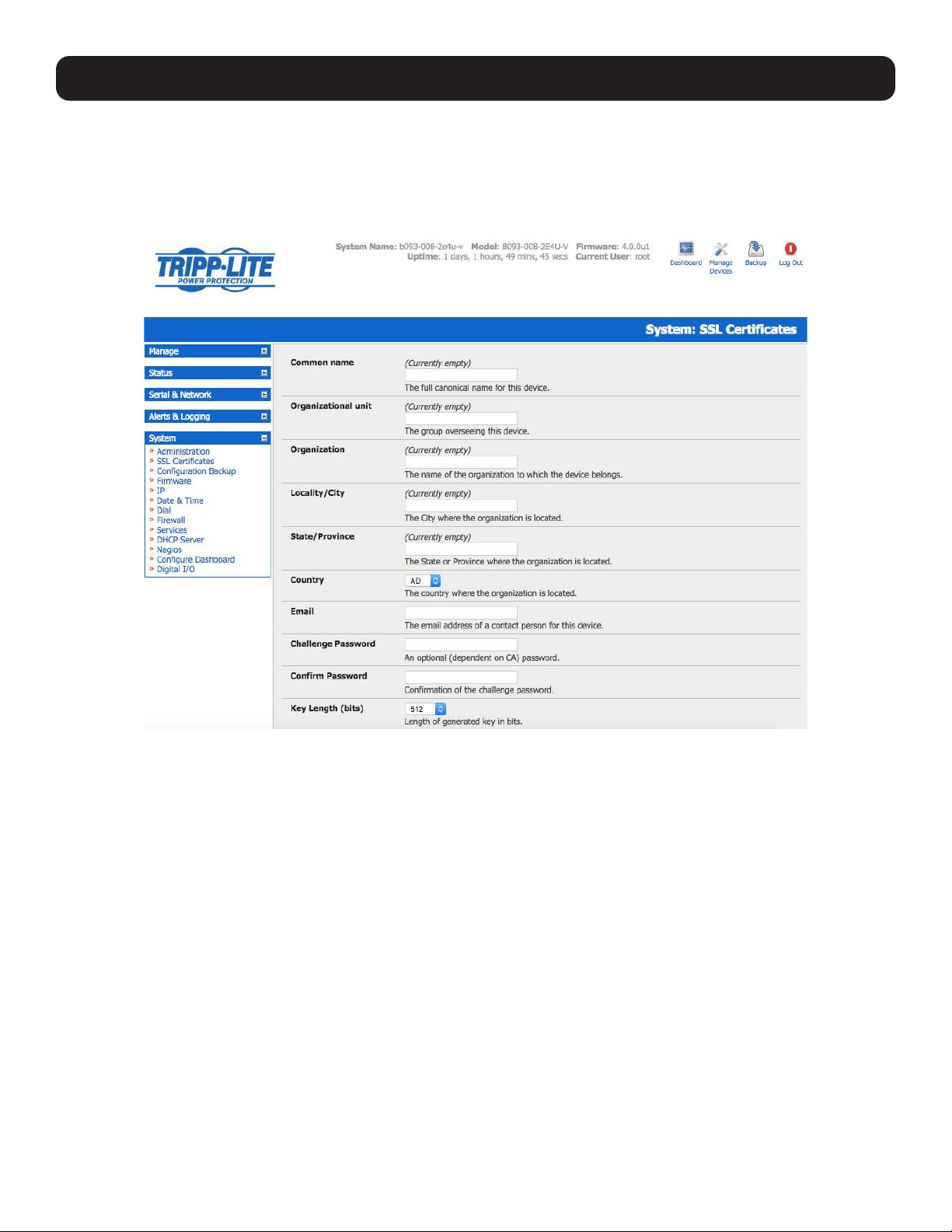
179
9. Authentication
Activate your preferred browser and enter https:/ / IP address. Your browser may respond with a message verifying the validity
of the security certificate, while noting that it is not necessarily verified by a trusted authority. To proceed, click Yes if using
Internet Explorer or select Accept this certificate permanently (or temporarily) if using Mozilla Firefox.
You will be prompted for the administrator account and password.
It is recommended you generate and install a new base64 X.509 certificate that is unique for a particular console server.

180
9. Authentication
The console server must be enabled to generate a new cryptographic key and the associated Certificate Signing Request (CSR)
that needs to be certified by a Certification Authority (CA). A certification authority verifies you are the person who you claim
you are and signs and issues you a SSL certificate. To create and install an SSL certificate for the console server:
• Select System: SSL Certificate and fill out the fields as explained below:
Common name: This is the network name of the console server once it is installed in the network (usually the fully qualified
domain name). It is identical to the name that is used to access the console server with a web browser (without the “http://”
prefix). In case the name given here and the actual network name differ, the browser will pop up a security warning when the
console server is accessed using HTTPS.
Organizational Unit: This field is used for specifying which department the console server belongs within an organization.
Organization: The name of the organization which the console server belongs.
Locality/City: The city where the organization is located.
State/Province: The state or province where the organization is located.
Country: The country where the organization is located. This is the two-letter ISO code (e.g., DE for Germany, or US for the
USA). The country code must be entered in capital letters.
Email: The email address of the contact person responsible for the console server and its security.
Challenge Password: Some certification authorities require a challenge password to authorize later changes on the
certificate (e.g., revocation of the certificate). The minimal password is 4 characters.
Confirm Challenge Password: Confirmation of the challenge password.
Key Length: This is the length of the generated key in bits. 1024 bits are sufficient for most cases. Longer keys may result
in slower console server response time when establishing a connection.
• Click on the Generate CSR button to initiate the Certificate Signing Request. The CSR can be downloaded to the
Administrator’s machine with the Download button.
• Send the saved CSR string to a Certification Authority (CA) for certification. A new certificate from the CA will be sent.
o Upload the certificate to the console server using the Upload button.
The console server should now have its own certificate that is used for identifying the console server to its users.
Note: Information on issuing certificates and configuring HTTPS from the command line can be found in 15. Advanced Configuration.
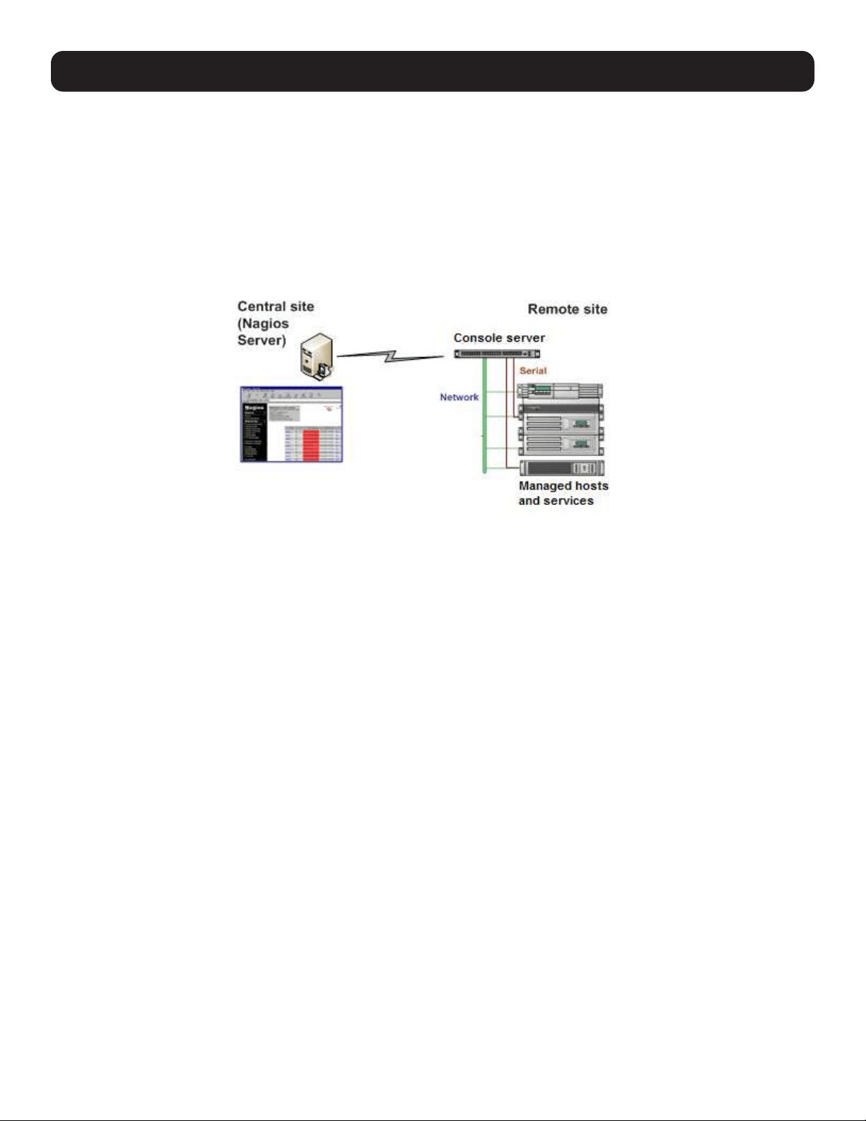
181
10. Nagios Integration
Nagios is a powerful and highly configurable open source tool for monitoring network hosts and services. The core Nagios
software package is typically installed on a server or virtual server, the central Nagios server.
Console servers operate in conjunction with a central/upstream Nagios server to provide distributing monitoring of attached
network hosts and serial devices. They embed the NSCA (Nagios Service Checks Acceptor) and NRPE (Nagios Remote Plug-
in Executor) add-ons, allowing them to communicate with the central Nagios server and eliminating the need for a dedicated
secondary Nagios server at remote sites.
Tripp Lite console servers support distributed monitoring. Even if distributed monitoring is not required, the console servers
can be deployed locally alongside the Nagios monitoring host serve, to provide additional diagnostics and points of access to
managed devices.
Note: If you have an existing Nagios deployment, you may wish to use the console server gateways in a distributed monitoring server
capacity only. If this is the case and you are already familiar with Nagios, skip to section 10.3 Advanced Distributed Monitoring
Configuration.
10.1 Nagios Overview
Nagios provides central monitoring of the hosts and services in your distributed network. Nagios is a free, downloadable, open
source software. This section provides a brief overview of Nagios and its capabilities. For a more comprehensive overview, visit
http://www.nagios.org.
10.2 Configuring Nagios Distributed Monitoring
To activate Nagios distributed monitoring on the console server:
• Nagios integration must be enabled and a path established to the central/upstream Nagios server.
• If the console server is to periodically report on Nagios monitored services, the NSCA client embedded in the console server
must be configured in order to enable scheduled check-ins with the remote Nagios server and send passive check results
across the network to the remote server.
• If the Nagios server is to actively request status updates from the console server, the NRPE server embedded in the console
server must be configured with the Nagios daemon for executing plug-ins on remote hosts.
• Each of the serial ports and hosts connected to the console server to be monitored must have Nagios enabled and any
specific Nagios checks configured.
• The central/upstream Nagios monitoring host must be configured.
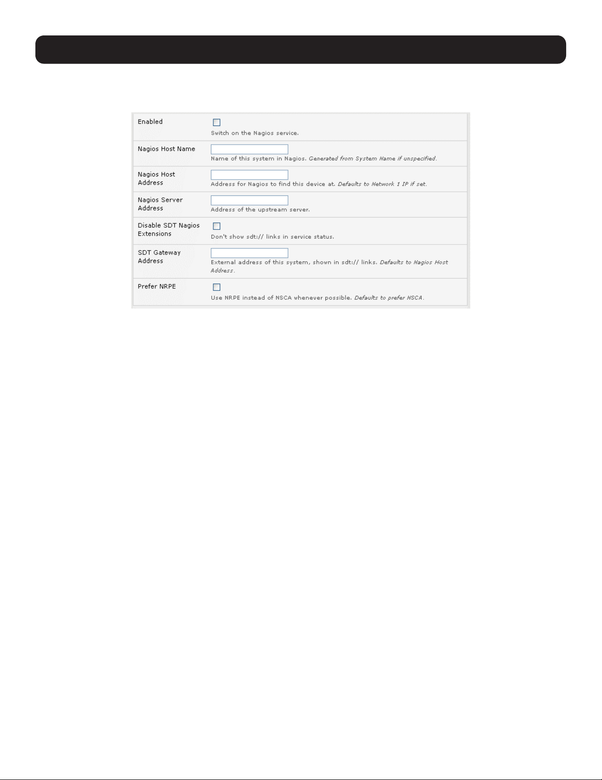
182
10. Nagios Integration
10.2.1 Enable Nagios on the Console Server
Select System: Nagios on the console server management console and check the service Enabled checkbox.
Enter the Nagios Host Name the console server will be referred to in the Nagios central server. This will be generated from
local System Name (entered in System: Administration) if unspecified.
In Nagios Host Address, enter the IP address or DNS name the upstream Nagios server will use to reach the console server.
If unspecified, this will default to the first network port’s IP (Network (1) as entered in System: IP).
In Nagios Server Address, enter the IP address or DNS name the console server will use to reach the upstream Nagios
monitoring server.
Check the Disable SDT Nagios Extensions option if you wish to disable the SDT connector integration with your Nagios
server at the head end. Only select this option if you want to run basic Nagios monitoring.
Otherwise, enter the IP address or DNS name the SDT Nagios clients will use to connect the console server in SDT Gateway
Address.
When NRPE and NSCA are both enabled, NSCA is the preferred method for communicating with the upstream Nagios server.
Make sure to check Prefer NRPE to use NRPE whenever possible (i.e., for all communication except for alerts).
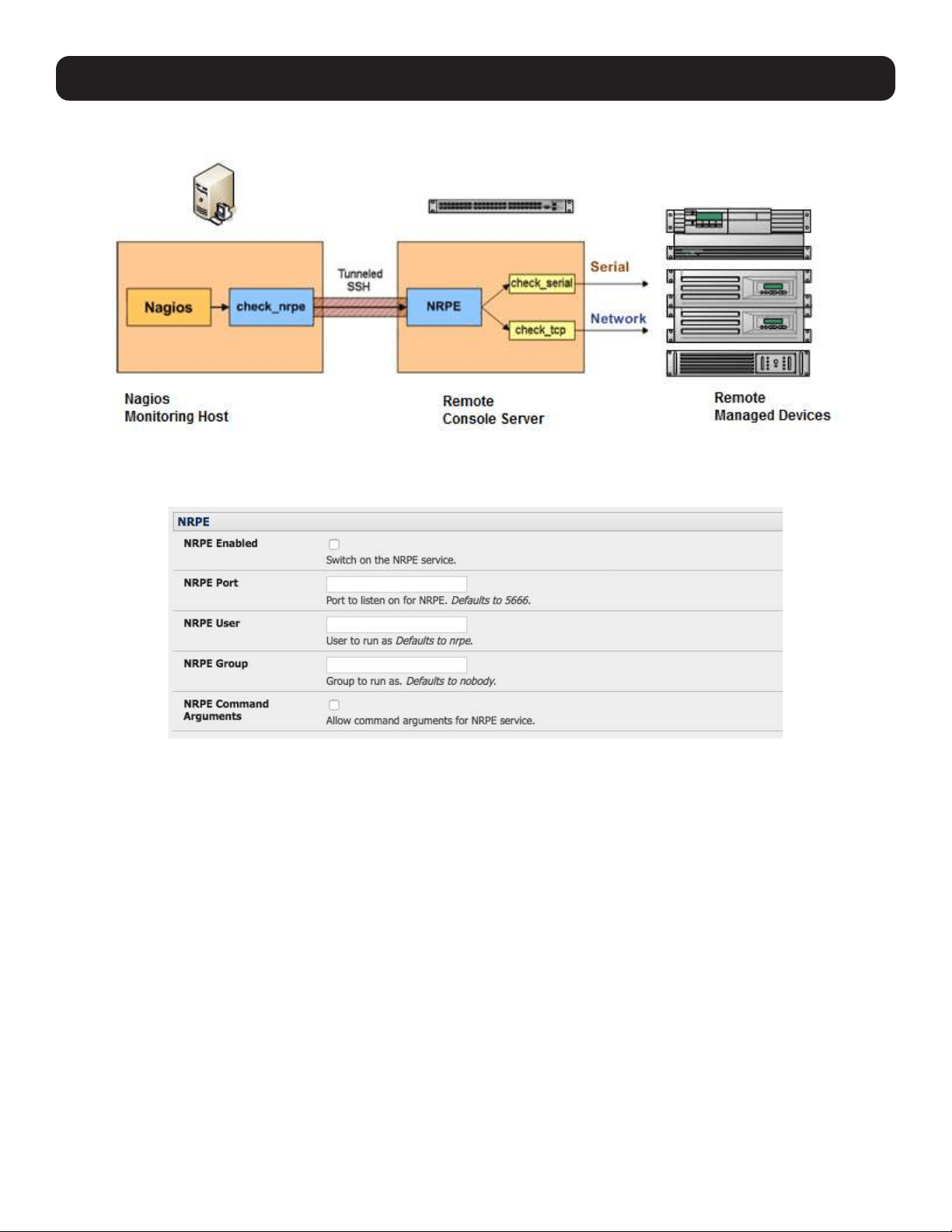
183
10.2.2 Enable NRPE Monitoring
Enabling NRPE allows you to execute plug-ins such as check_tcp and check_ping on the remote console server to monitor
serial or network attached remote servers. This will offload the CPU from the upstream Nagios monitoring machine, which is
especially valuable if monitoring hundreds or thousands of hosts. To enable NRPE:
• Select System: Nagios and check NRPE Enabled.
• Enter the user details to connect the upstream Nagios monitoring server. Refer to the sample Nagios configuration example
below for details of configuring specific NRPE checks.
By default, the console server will accept a connection between the upstream Nagios monitoring server and the NRPE server
with SSL encryption, without SSL, or tunneled through SSH. The security for the connection is configured at the Nagios server.
10. Nagios Integration
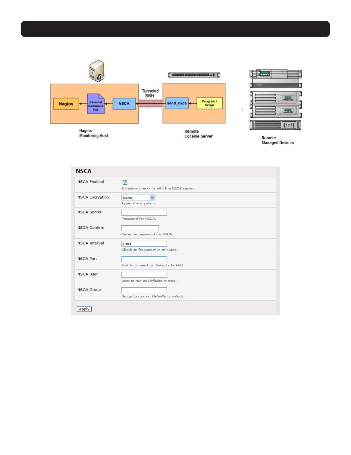
184
10. Nagios Integration
10.2.3 Enable NSCA Monitoring
NSCA sends passive check results from the remote console server to the Nagios daemon running on the monitoring server. To
enable NSCA:
• Select System: Nagios and check NSCA Enabled.
• Select the Encryption to be used from the dropdown menu. Enter a Secret password and specify a check Interval.
• Refer to the sample Nagios configuration section below for examples of configuring specific NSCA checks.
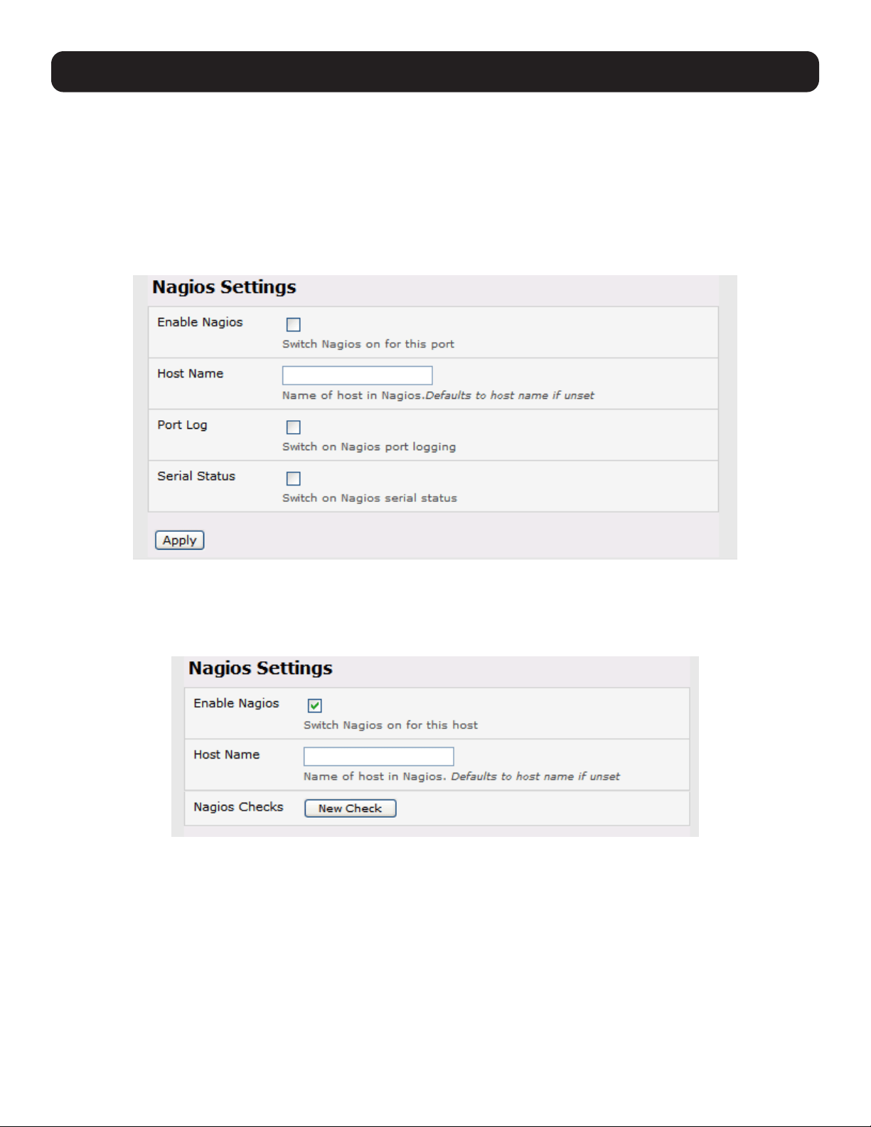
185
10.2.4 Configure Selected Serial Ports for Nagios Monitoring
Individual serial ports connected to the console server to be monitored must be configured for Nagios checks (refer to 4.4
Network Host Configuration for details on enabling Nagios monitoring for hosts that are network-connected to the console
server). To enable Nagios to monitor a device connected to the console server serial port:
• Select Serial & Network: Serial Port and click Edit on the serial port to be monitored.
• Select Enable Nagios, specify the name of the device on the upstream server and determine the check to be run on this
port. Serial Status monitors the handshaking lines on the serial port and Check Port monitors the data logged for the
serial port.
10.2.5 Configure Selected Network Hosts for Nagios Monitoring
The individual network hosts connected to the console server to be monitored must also be configured for Nagios checks:
• Select Serial & Network: Network Port and click Edit on the network host to be monitored.
• Select Enable Nagios and specify the name of the device as it will appear on the upstream Nagios server.
• Click New Check to add a specific check to be run on this host.
• Select Check Permitted TCP/UDP to monitor a service you have previously added as a Permitted Service.
• Select Check TCP/UDP to specify a service port you wish to monitor, but do not wish to allow external (SDT Connector)
access to.
• Select Check TCP to monitor.
10. Nagios Integration
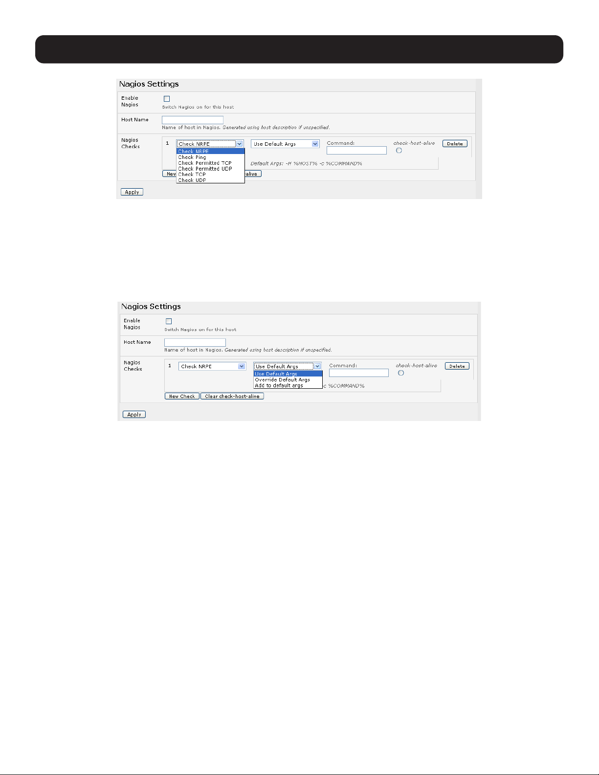
186
10. Nagios Integration
• The Nagios Check assigned as the check-host-alive check determines whether the network host is up or down.
• Typically, this will be Check Ping. In some cases, the host will be configured to not respond to pings.
• If no check-host-alive is selected, the host will always be assumed to be up.
• You may deselect check-host-alive by clicking Clear check-host-alive.
• If required, customize the selected Nagios Checks to use custom arguments.
• Click Apply.
10.2.6 Configure the Upstream Nagios Monitoring Host
Refer to the Nagios documentation (found at http://www.nagios.org/docs/) for configuring the upstream server:
• The section Distributed Monitoring provides step-by-step detail for configuring NSCA on the upstream server (under
Central Server Configuration).
• NRPE Documentation has recently added steps for configuring NRPE on the upstream server. For more information, visit
http://nagios.sourceforge.net/docs/nrpe/NRPE.pdf.
At this point, Nagios upstream monitoring server has been configured and individual serial port and network host connections
on the console server have been configured for Nagios monitoring. If NSCA is enabled, each selected check will be executed
once over the period of the check interval. If NRPE is enabled, the upstream server will be able to request status updates
under its own scheduling.

187
10. Nagios Integration
10.3 Advanced Distributed Monitoring Configuration
10.3.1 Sample Nagios Configuration
An example configuration for Nagios is listed below. The example configuration shows how to set up a remote console server
to monitor a single host with both network and serial connections. Each check contains two configurations: one for NRPE and
one for NSCA. In practice, these would be combined into a single check using NSCA as a primary method and defaulting to
NRPE if checked late. For more information, refer to Nagios documentation (http://www.nagios.org/docs/) on Service and
Host Freshness Checks.
; Host definitions
;
; Tripp Lite Console server
define host{
use generic-host
host_name tripp-lite
alias Console server
address 192.168.254.147
}
; Managed Host
define host{
use generic-host
host_name server
alias server
address 192.168.254.227
}
; NRPE daemon on gateway
define command {
command_name check_nrpe_daemon
command_line $USER1$/check_nrpe -H 192.168.254.147 -p 5666
}
define service {
service_description NRPE Daemon
host_name tripp-lite
use generic-service
check_command check_nrpe_daemon
}
; Serial Status
define command {
command_name check_serial_status
command_line $USER1$/check_nrpe -H 192.168.254.147 -p 5666 -c check_serial_$HOSTNAME$
}
define service {
service_description Serial Status
host_name server
use generic-service
check_command check_serial_status
}
define service {
service_description serial-signals-server
host_name server
use generic-service
check_command check_serial_status
active_checks_enabled 0
passive_checks_enabled 1
}

188
10. Nagios Integration
define servicedependency{
name tripp-lite_nrpe_daemon_dep
host_name tripp-lite
dependent_host_name server
dependent_service_description Serial Status
service_description NRPE Daemon
execution_failure_criteria w,u,c
}
; Port Log
define command{
command_name check_port_log
command_line $USER1$/check_nrpe -H 192.168.254.147 -p 5666 -c port_log_$HOSTNAME$
}
define service {
service_description Port Log
host_name server
use generic-service
check_command check_port_log
}
define service {
service_description port-log-server
host_name server
use generic-service
check_command check_port_log
active_checks_enabled 0
passive_checks_enabled 1
}
define servicedependency{
name tripp-lite_nrpe_daemon_dep
host_name tripp-lite
dependent_host_name server
dependent_service_description Port Log
service_description NRPE Daemon
execution_failure_criteria w,u,c
}
; Ping
define command{
command_name check_ping_via_tripp-lite
command_line $USER1$/check_nrpe -H 192.168.254.147 -p 5666 -c host_ping_$HOSTNAME$
}
define service {
service_description Host Ping
host_name server
use generic-service
check_command check_ping_via_tripp-lite
}
define service {
service_description host-ping-server
host_name server
use generic-service
check_command check_ping_via_tripp-lite
active_checks_enabled 0
passive_checks_enabled 1
}

189
10. Nagios Integration
define servicedependency{
name tripp-lite_nrpe_daemon_dep
host_name tripp-lite
dependent_host_name server
dependent_service_description Host Ping
service_description NRPE Daemon
execution_failure_criteria w,u,c
}
; SSH Port
define command{
command_name check_conn_via_tripp-lite
command_line $USER1$/check_nrpe -H 192.168.254.147 -p 5666 -c host_$HOSTNAME$_$ARG1$_$ARG2$
}
define service {
service_description SSH Port
host_name server
use generic-service
check_command check_conn_via_tripp-lite!tcp!22
}
define service {
service_description host-port-tcp-22-server
; host-port-<protocol>-<port>-<host>
host_name server
use generic-service
check_command check_conn_via_tripp-lite!tcp!22
active_checks_enabled 0
passive_checks_enabled 1
}
define servicedependency{
name tripp-lite_nrpe_daemon_dep
host_name tripp-lite
dependent_host_name server
dependent_service_description SSH Port
service_description NRPE Daemon
execution_failure_criteria w,u,c
}
10.3.2 Basic Nagios Plug-Ins
Plug-ins are compiled executables or scripts that can be scheduled to be run on the console server to check the status of a
connected host or service. This status is then communicated to the upstream Nagios server, which uses the results to monitor
the current status of the distributed network. Each console server is preconfigured with checks that are part of the Nagios
plug-ins package:
check_tcp and check_udp are used to check open ports on network hosts.
check_ping is used to check network host availability.
check_nrpe is used to execute arbitrary plug-ins in other devices.
Each console server is preconfigured with two checks that are specific to Tripp Lite:
check_serial_signals is used to monitor the handshaking lines on the serial ports.
check_port_log is used to monitor the data logged for a serial port.

190
10. Nagios Integration
10.3.3 Additional Plug-Ins
Additional Nagios plug-ins (listed below) are available for all B097 and B098 models:
check_apt
check_by_ssh
check_clamd
check_dig
check_dns
check_dummy
check_fping
check_ftp
check_game
check_hpjd
check_http
check_imap
check_jabber
check_ldap
check_load
check_mrtg
check_mrtgtraf
check_nagios
check_nntp
check_nntps
check_nt
check_ntp
check_nwstat
check_overcr
check_ping
check_pop
check_procs
check_real
check_simap
check_smtp
check_snmp
check_spop
check_ssh
check_ssmtp
check_swap
check_tcp
check_time
check_udp
check_ups
check_users
Bash scripts can also be downloaded and run (primarily check_log.sh).
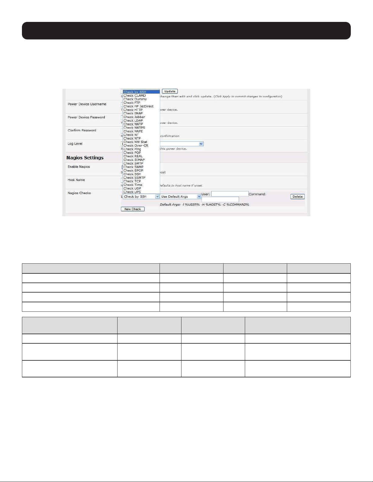
191
10. Nagios Integration
To configure additional checks, the downloaded plug-in program must be saved in the tftp addins directory on the USB flash
and the downloaded text plug-in file saved in /etc/config.
To enable these new additional checks, select Serial & Network: Network Port. Select Edit for the network host to be
monitored and New Checks. The additional check option will be included in the updated Nagios Checks list, where you can
again customize the arguments.
10.3.4 Number of Supported Devices
The number of devices that can be supported by a console server is a function of the number of checks being made and how
often they are performed. Access method also plays a role. The table below shows the performance of three console server
models (1/2 port, 8 port and 16/48 port):
Time No encryption 3DES SSH tunnel
NSCA for single check ~ ½ second ~ ½ second ~ ½ second
NSCA for 100 sequential checks 100 seconds 100 seconds 100 seconds
NSCA for 10 sequential checks, batched upload 1 ½ seconds 2 seconds 1 second
NSCA for 100 sequential checks, batched upload 7 seconds 11 seconds 6 seconds
No encryption SSL
no encryption - tunneled over
existing SSH session
NRPE time to service 1 check 1/10th second 1/3rd second 1/8th second
NRPE time to service
10 simultaneous checks
1 second 3 seconds 1 ¼ seconds
Maximum number of simultaneous
checks before timeouts
30
20 (1,2 and 8) or
25 (16 and 48 port)
25 (1,2 and 8 port),
35 (16 and 48 port)
The results were from running tests five times in succession with no timeouts on any runs. However, there are a number of
ways to increase the number of checks you can do:
When using NRPE checks, an individual request will need to set up and tear down an SSL connection. This overhead can be
avoided by setting up an SSH session to the console server and tunneling the NRPE port. This allows the NRPE daemon to run
securely without SSL encryption, as SSH will handle security.
When the console server submits NSCA results, it staggers them over a time period (e.g., 20 checks over 10 minutes will
result in two check results every minute). Staggering the results like this means that in the event of a power failure or other
incident that causes multiple problems, the individual refresh checks will be staggered too.
NSCA checks are also batched. In the previous example, the two checks per minute will be sent through in a single
transaction.
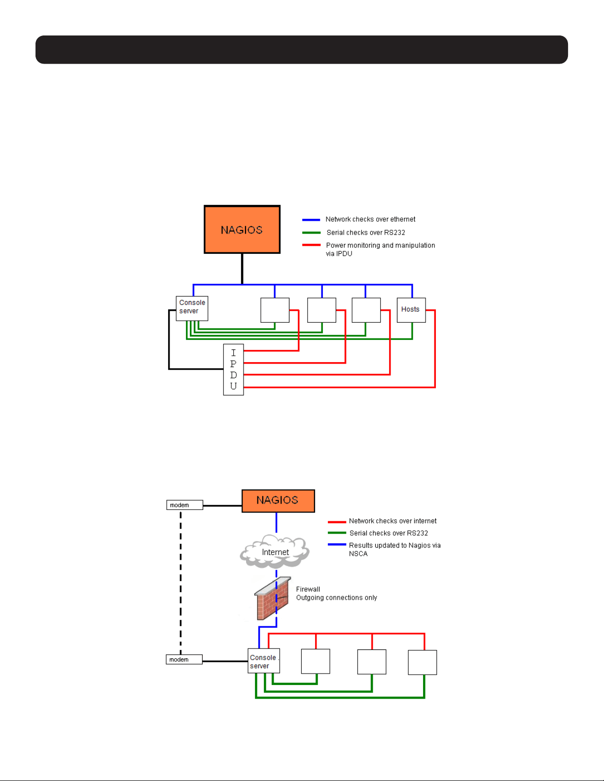
192
10. Nagios Integration
10.3.5 Distributed Monitoring Usage Scenarios
Below are examples of distributed monitoring Nagios scenarios:
Local office
In this scenario, the console server is set up to monitor the console of each managed device. It can be configured to perform a
number of checks (actively at the Nagios server’s request, or passively at preset intervals) and submit the results to the Nagios
server in a batch.
The console server may be augmented at the local office site by one or more Intelligent Power Distribution Units (IPDUs) to
remotely control the power supply to the managed devices.
Remote site
In this scenario, the console server, NRPE server or NSCA client can be configured to make active checks of configured
services and upload to the Nagios server waiting passively. It can also be configured to service NRPE commands to perform
checks on demand.
In this situation, the console server will perform checks based on both serial and network access.
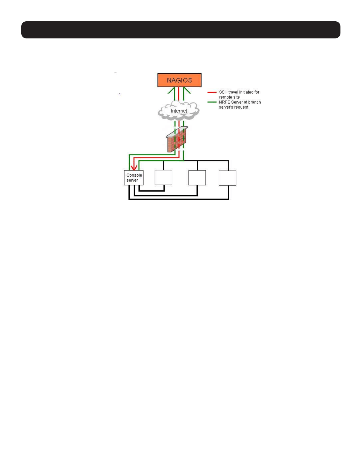
193
Remote Site with Restrictive Firewall
In this scenario, the console server’s role will vary. One aspect may be to upload check results through NSCA. Another may be
to provide an SSH tunnel to allow the Nagios server to run NRPE commands.
Remote Site with No Network Access
In this scenario, the console server allows dial-in access to the Nagios server. Periodically, the Nagios server will establish a
connection to the console server and execute any NRPE commands before dropping the connection.
10. Nagios Integration
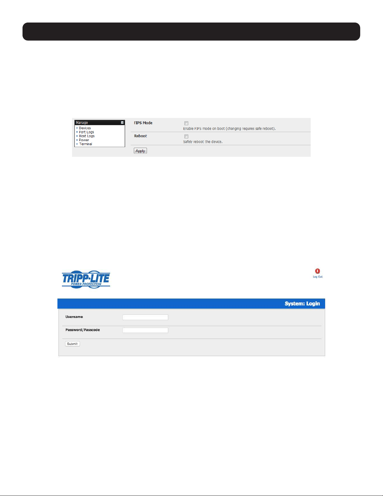
194
11. System Management
This chapter describes how the Administrator can perform a range of general console server system administrative and
configuration tasks.
11.1 System Administration and Reset
The Administrator can reboot or reset the gateway to default settings.
To perform a soft reset:
• Select Reboot in the System: Administration menu and click Apply.
The console server reboots with all settings (e.g., the assigned network IP address) preserved. However, this soft reset
disconnects all users and ends any SSH sessions that had been established.
A soft reset will also be affected when you switch OFF power from the console server and switch the power back ON. If you
cycle the power and the unit is writing data to flash memory, you could corrupt or lose data. As such, a software reboot is the
safer option.
To perform a hard erase (hard reset):
• Push the Erase button on the rear panel twice. A ballpoint pen or bent paper clip is a suitable tool for performing this
procedure. Do not use a graphite pencil. Depress the button gently twice (within a couple of second period) while the unit
is powered ON.
This will reset the console server to its factory default settings and clear the console server’s stored configuration information
(i.e. the IP address will be reset to 192.168.0.1). You will be prompted to log in and must enter the default administration
username and administration password (Username: root Password: default).
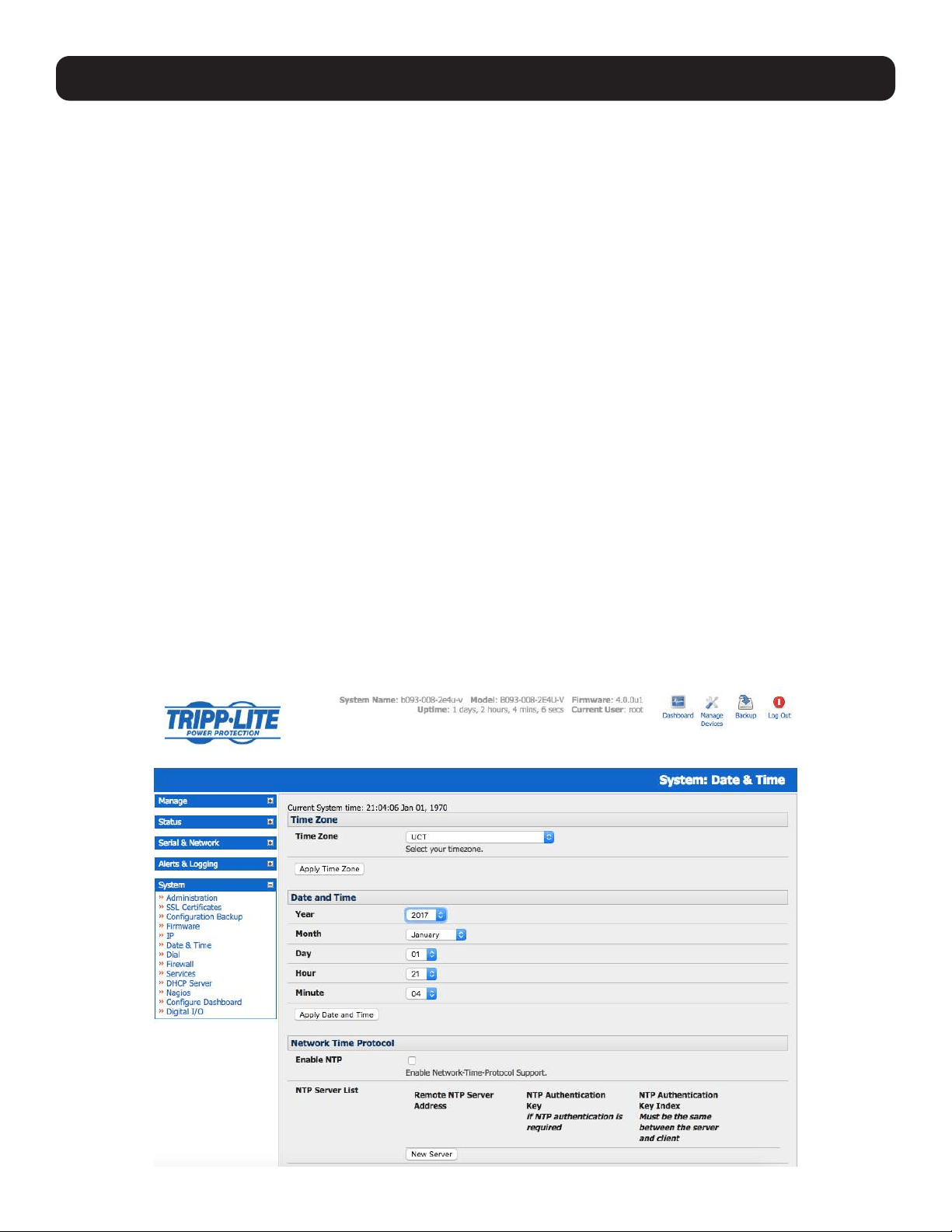
195
11. System Management
11.2 Upgrade Firmware
Before upgrading, you should determine whether your Tripp Lite device is running the most current firmware. Your Tripp Lite
device will not allow you to upgrade to the same version or an earlier version.
• The Firmware version is displayed in the header of each page.
• Alternately, selecting Status: Support Report reports the Firmware Version.
• To upgrade, you first must download the latest firmware image from www.tripplite.com/support.
• Save this downloaded firmware image file on to a system on the same subnet as the Tripp Lite device.
• Download and read the Release Notes file for the latest update information.
• To upload the firmware image file, select System: Firmware.
• Specify the address and name of the downloaded Firmware Upgrade File, or Browse the local subnet and locate the
downloaded file.
• Click Apply. The Tripp Lite device will undergo a soft reboot and begin upgrading the firmware. This process will take several
minutes.
• After the firmware upgrade has completed, click here to return to the management console. Your Tripp Lite device will have
retained all pre-upgrade configuration information.
11.3 Configure Date and Time
It is important to set the local date and time in your Tripp Lite device as soon as it is configured. Features such as Syslog and
NFS logging use the system time for time-stamping log entries, while certificate generation depends on a correct timestamp to
check the validity period of the certificate.
Your Tripp Lite appliance can synchronize its system time with a remote Network Time Protocol (NTP) server. NTP uses
Coordinated Universal Time (UCT) for all time synchronizations, so it is not affected by different time zones. However, you will
need to specify your local time zone in order for the system clock to show the correct local time:
• Set your appropriate region/locality in the Time Zone selection box and click Set Timezone.
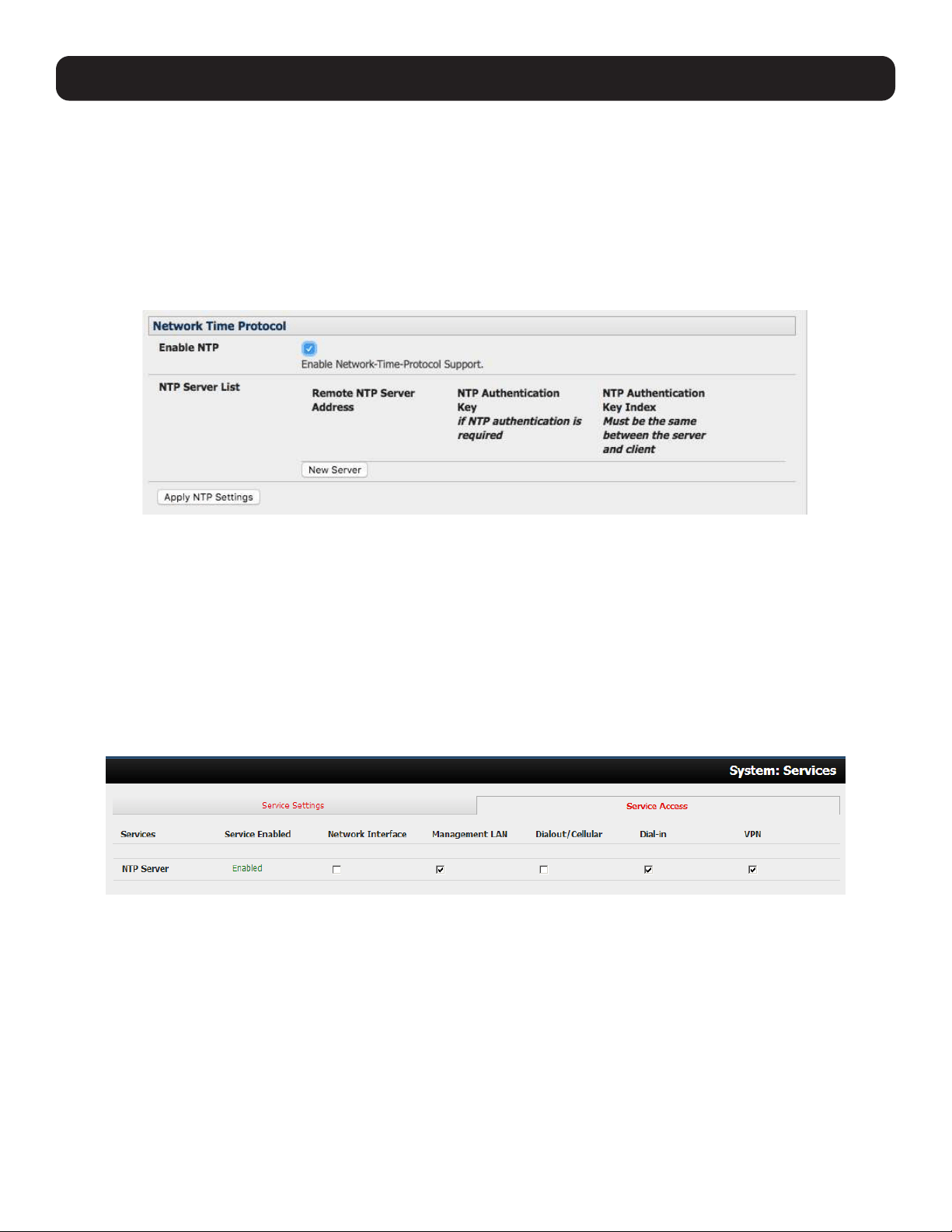
196
11. System Management
Note: With firmware version 3.2.0, the time zone can also be set to UCT, which replaced Greenwich Mean Time (GMT) as the world
standard for time.
Configuring NTP ensures the Tripp Lite device’s clock is accurate (once Internet connection has been established).
• Select the Enable NTP checkbox in the Network Time Protocol section of the System: Date & Time page.
• Enter the IP address of the remote NTP Server.
• If your external NTP server requires authentication, specify the NTP Authentication Key and the Key Index to use when
authenticating with the NTP server.
• Click Apply NTP Settings.
If remote NTP is not used, the time can be set manually:
• Enter the Year, Month, Day, Hour and Minute using the Date and Time selection boxes.
• Check Set Time.
Notes:
• All Tripp Lite devices have an internal battery-backed hardware clock. When the time and date is set manually through the management
console or retrieved from an NTP server, the hardware clock of the Tripp Lite device is automatically updated. The hardware clock uses a
battery to allow the current time and date to be maintained across reboots and after the appliance has been powered down for longer
periods.
• With the NTP peering model, the Tripp Lite device can share its time information with other devices connected to it so all devices can be
time synchronized. To do this, click Enable NTP on the Time and Date page and ensure the appropriate networks are selected on the
Service Access tab under System: Services.
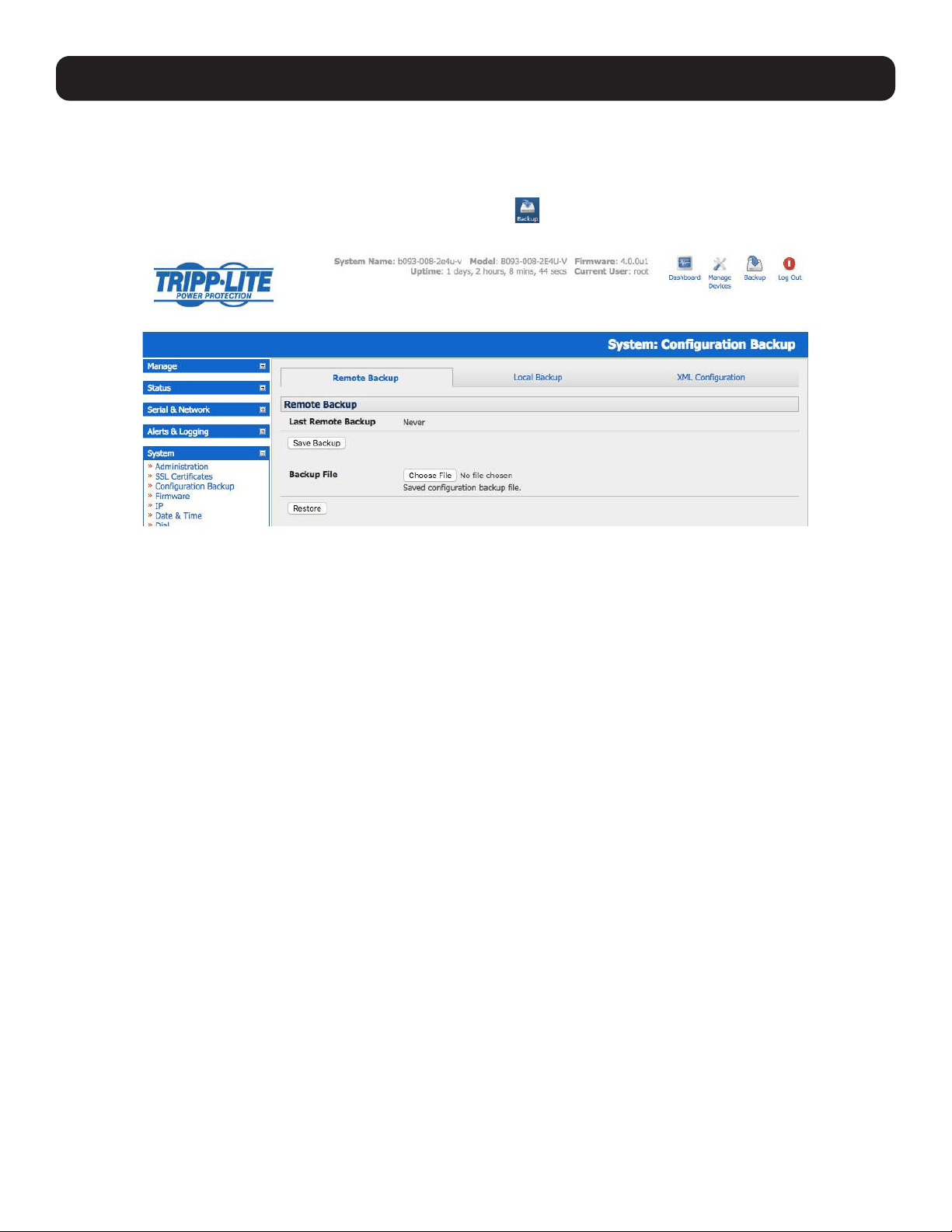
197
11. System Management
11.4 Configuration Backup
It is recommended that you back up the console server configuration whenever you make significant changes (such as adding
new users or managed devices) or before performing a firmware upgrade.
Select the System: Configuration Backup menu option or click the icon.
Note: The configuration files can also be backed up from the command line (refer to 14. Configuration from the Command Line).
With all console server models, you can save the backup file remotely on your PC and restore configurations from remote
locations:
• Click Save Backup in the Remote Configuration Backup menu.
• The config backup file (System Name_date_config.opg) will be downloaded to your PC and saved in the location you
assign.
To restore a remote backup:
• Click Browse in the Remote Configuration Backup menu and select the Backup File you wish to restore.
• Click Restore, then click OK. This will overwrite all current configuration settings in your console server.
Some console server models allow you to save the backup file locally onto the USB storage. To do so, your console server
must support USB and have an internal or external USB flash drive installed.
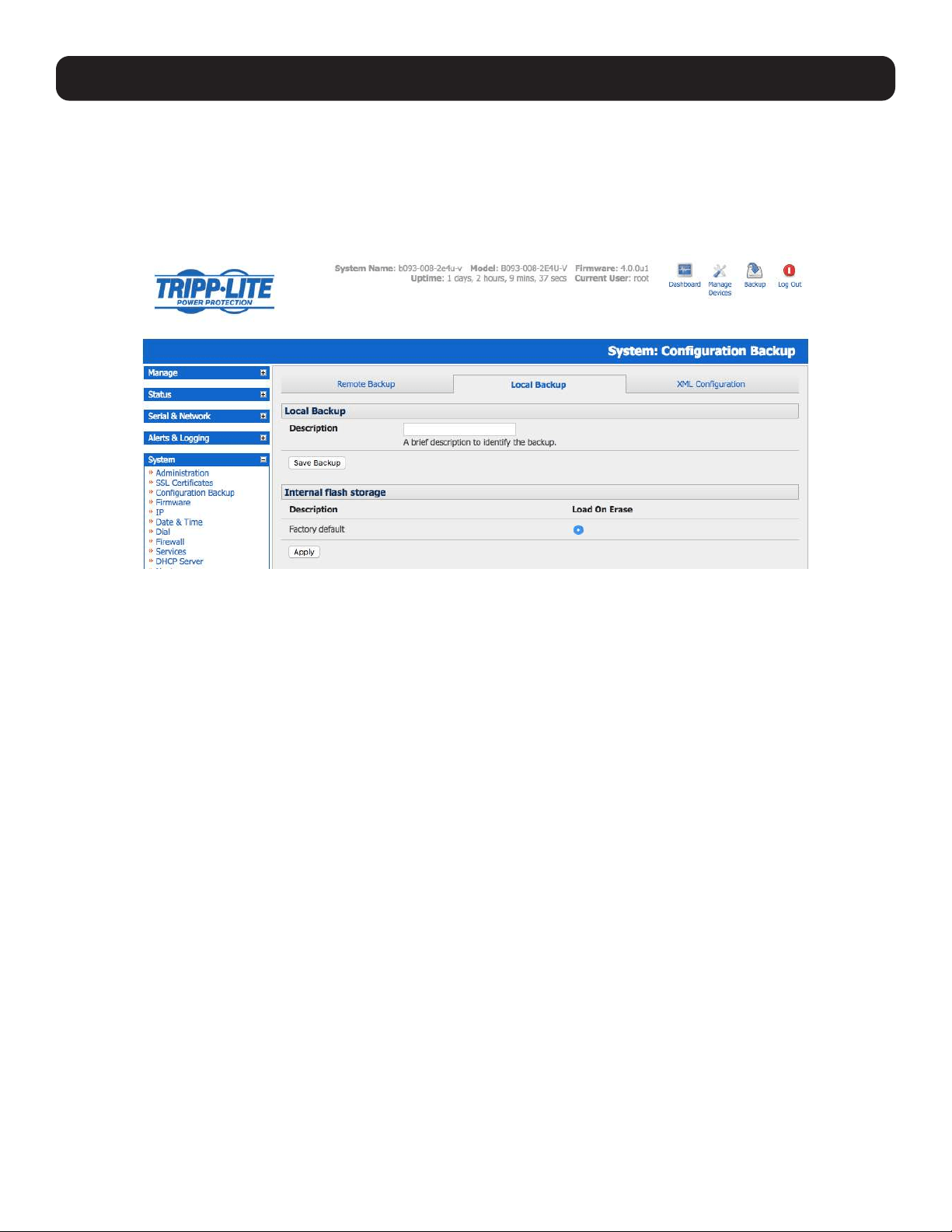
198
11. System Management
To backup and restore using USB:
• Ensure the USB flash is the only USB device attached to the console server.
• Select the Local Backup tab and click here to proceed. This will set a volume label on the USB storage device. This
preparation step is only necessary the first time and will not affect any other information saved onto the USB storage device.
It is recommended you back up any critical data from the USB storage device before using it with your console server. If
there are multiple USB devices installed, you will be asked to remove them.
• To back up to USB, enter a brief Description of the backup in the Local Backup menu and select Save Backup.
• The Local Backup menu will display all configuration backup files stored onto the USB flash.
• To restore a backup from the USB, simply select Restore on the particular backup you wish to restore and click Apply.
After saving a local configuration backup, you may choose to use it as the alternate default configuration. When the console
server is reset to factory default, it will load your alternate default configuration (instead of its factory settings):
• To set an alternate default configuration, check Load On Erase and click Apply.
Note: Before selecting Load On Erase, ensure you have tested your alternate default configuration by clicking Restore.
If for some reason your alternate default configuration causes the console server to become unbootable, recover your unit to factory settings
using the following steps:
• If the configuration is stored on an external USB storage device, unplug the storage device and reset to factory defaults (refer to 11.1
System Administration and Reset).
• If the configuration is stored on an internal USB storage device, reset to factory defaults using a specially prepared USB storage device:
o The USB storage device must be formatted with a Windows FAT32/VFAT file system on the first partition or the entire disk (most USB
thumb drives are already formatted this way).
o The file system must have the volume label: OPG_DEFAULT.
o Insert this USB storage device into an external USB port on the console server and reset to factory defaults as per section 11.1 System
Administration and Reset.
After recovering your console server, ensure the problematic configuration is no longer selected for Load On Erase.
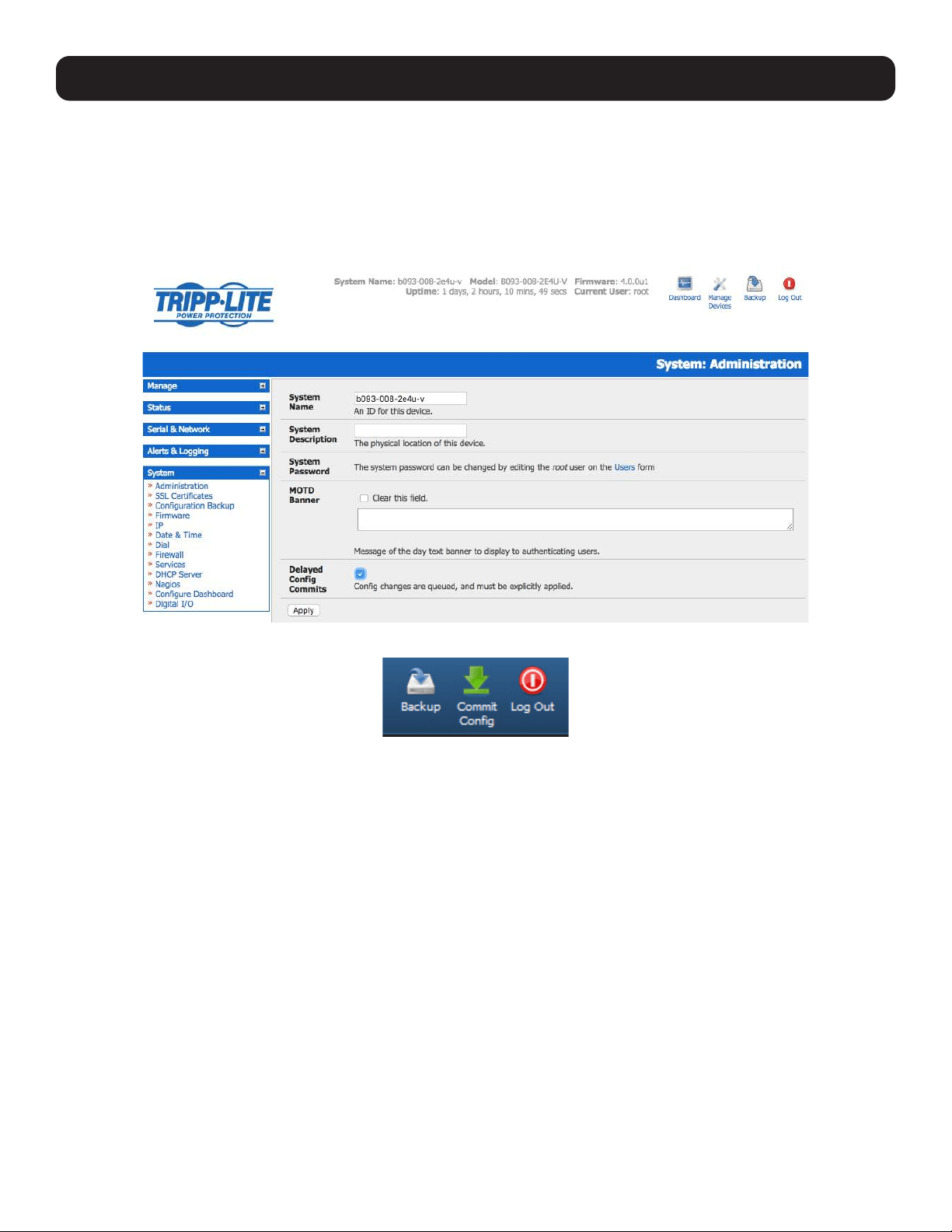
199
11. System Management
11.5 Delayed Configuration Commit
This mode allows the grouping or queuing of configuration changes and the simultaneous application of these changes to a
specific device. For example, changes to authentication methods or user accounts may be grouped and run once to minimize
system downtime. To enable:
• Check the Delayed Config Commits button under System: Administration.
• Click Apply.
• The Commit Config icon will display in top right-hand corner of the screen between the Backup and Log Out icons.
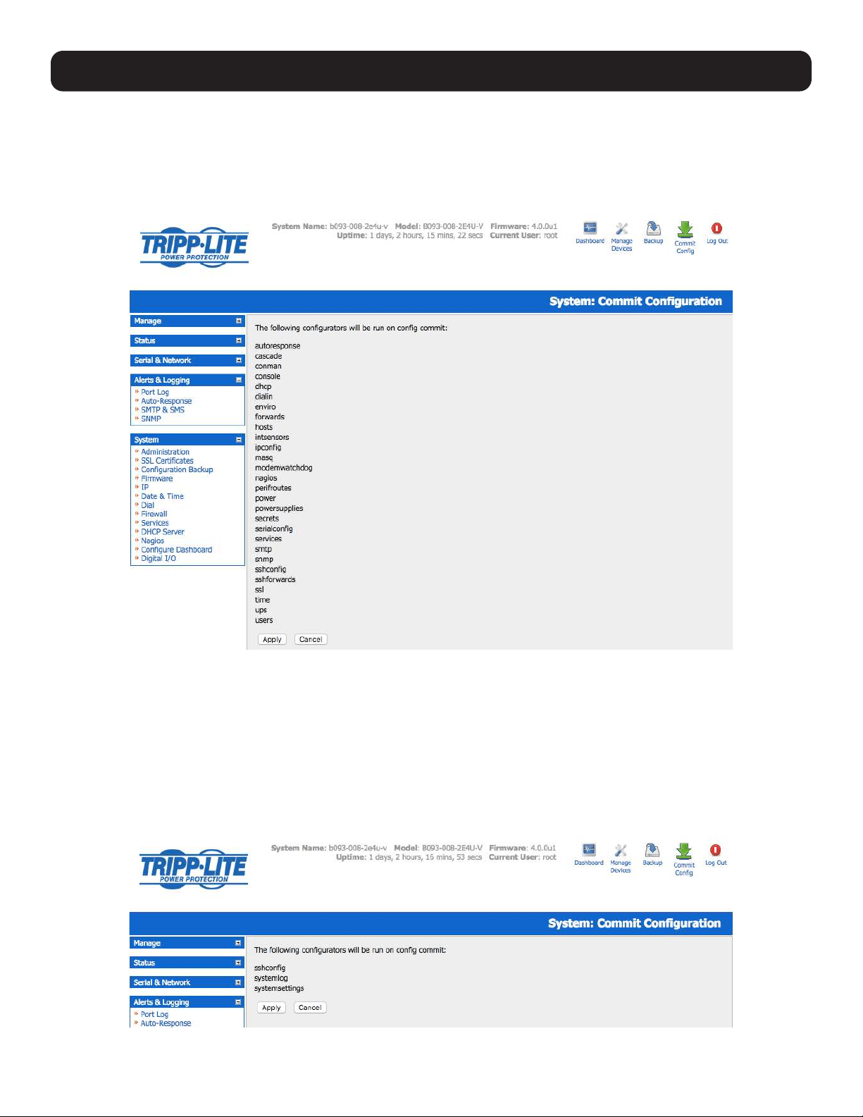
200
11. System Management
To queue, then run configuration changes:
• First, apply all the required changes to the configuration (e.g., modify user accounts, amend authentication method, enable
OpenVPN tunnel or modify system time).
• Click the Commit Config button. This will generate the System: Commit Configuration screen displaying all the
configurators to be run.
• Click Apply to run all configurators in the queue.
• Alternately, click Cancel. This will discard all the delayed configuration changes.
Note: All queued configuration changes will be lost if Cancel is selected.
To disable the Delayed Configuration Commits mode:
• Uncheck the Delayed Config Commits button under System: Administration and click Apply.
• Click the Commit Config button in top right-hand corner of the screen to display the System: Commit Configuration
screen.
• Click Apply to run the systemsettings configurator.
The Commit Config button will no longer display in the top right-hand corner of the screen and configurations will no longer be
queued.
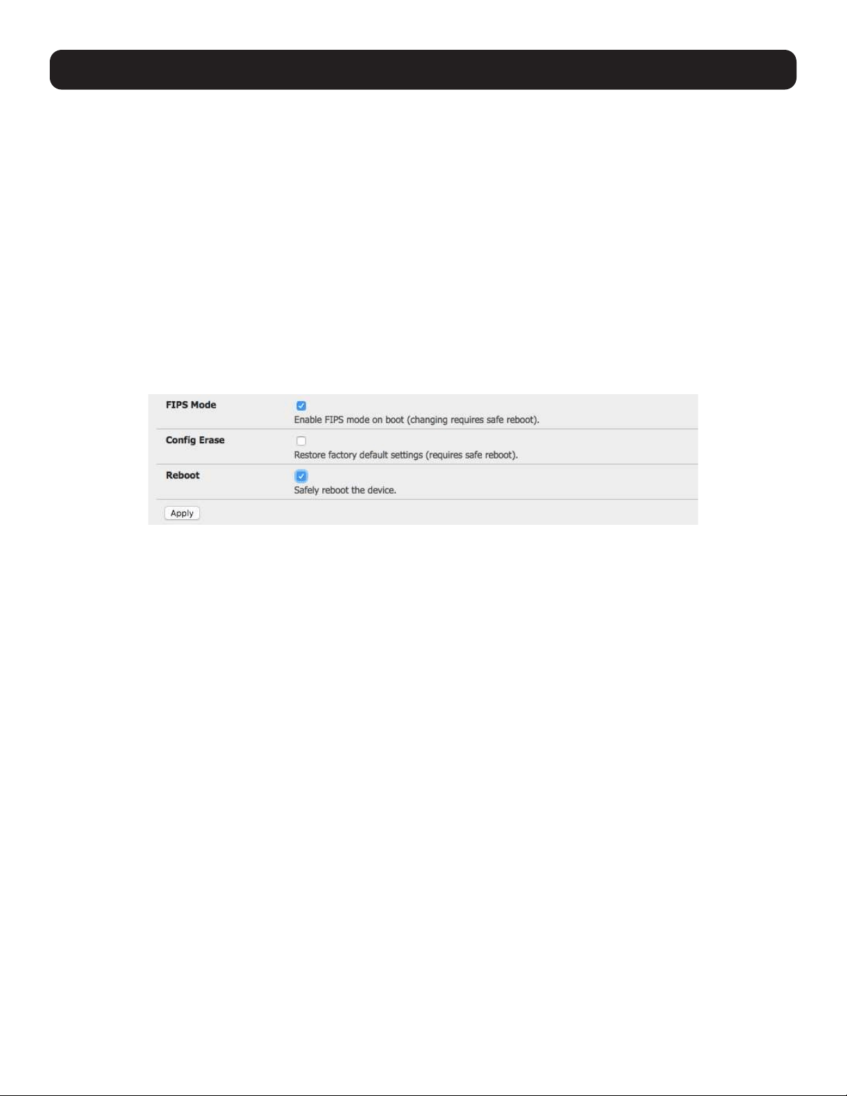
201
11.6 FIPS Mode
All Tripp Lite console server models use an embedded cryptographic module that has been validated to meet the FIPS 140-2
standards.
Note: The US National Institute of Standards and Technology (NIST) publishes the FIPS (Federal Information Processing Standard) series
of standards. FIPS 140-1 and FIPS 140-2 are both technical standards and worldwide de-facto standards for the implementation of
cryptographic modules. These standards and guidelines are issued by NIST for use government-wide. NIST develops FIPS when there are
compelling Federal government requirements such as for security and interoperability and there are no acceptable industry standards or
solutions.
Tripp Lite advance console servers use an embedded OpenSSL cryptographic module that has been validated to meet the FIPS 140-2
standards and has received Certificate #1051.
When configured in FIPS mode, all SSH, HTTPS and SDT Connector access to all services on the advanced console servers
will use the embedded FIPS-compliant cryptographic module. To connect, you must also use FIPS-approved cryptographic
algorithms found in your browser or client. Otherwise, the connection will fail.
• Select the System: Administration menu option.
• Check FIPS Mode to enable FIPS mode on boot, then check Reboot to safely reboot the console server.
• Click Apply. The console server will now reboot. It will take several minutes to reconnect as secure communications with
your browser are validated. When reconnected, it will display “FIPs mode: Enabled” in the banner.
Note: To enable FIPS mode from the command line, login and run these commands:
config -s config.system.fips=on
touch /etc/config/FIPS
chmod 444 /etc/config/FIPS
flatfsd -b
The final command saves to flash and reboots the unit. The unit will take a few minutes to boot into FIPS mode. To disable FIPS mode:
config -d config.system.fips
rm /etc/config/FIPS
flatfsd –b
11. System Management
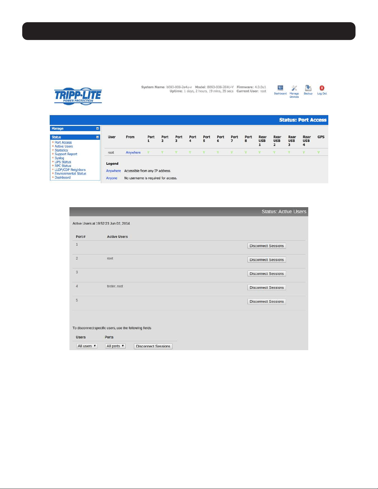
202
12. Status Reports
12.1 Port Access and Active Users
The Administrator can see which Users have access privileges with which serial ports:
• Select Status: Port Access.
The Administrator can also see the current status of Users who have active sessions on those ports:
• Select Status: Active Users.
With firmware version 3.11 and later, the Status: Active Users menu has been extended to enable Administrators to
selectively terminate serial sessions. Telnet, SSH, raw TCP and unauthenticated telnet connections can be disconnected.
However, you cannot disconnect an RFC2217 session.
The root user or any user in the admin group can access the Active Users page, which shows a snapshot of the connected
sessions with a timestamp displayed at the top of the page. This page only shows the local console ports, and does not
include any cascaded ports.
There are Disconnect Sessions buttons along the right hand side of the table listing active users. These buttons disconnect
all sessions from the port they correspond to. If the port is not set up in console server mode, the user will see a pop up error
informing them that the port needs to be configured in console server mode before they can connect and disconnect.
After the buttons have been pressed, the selected sessions will be disconnected and the number of disconnect sessions will
display to the user.
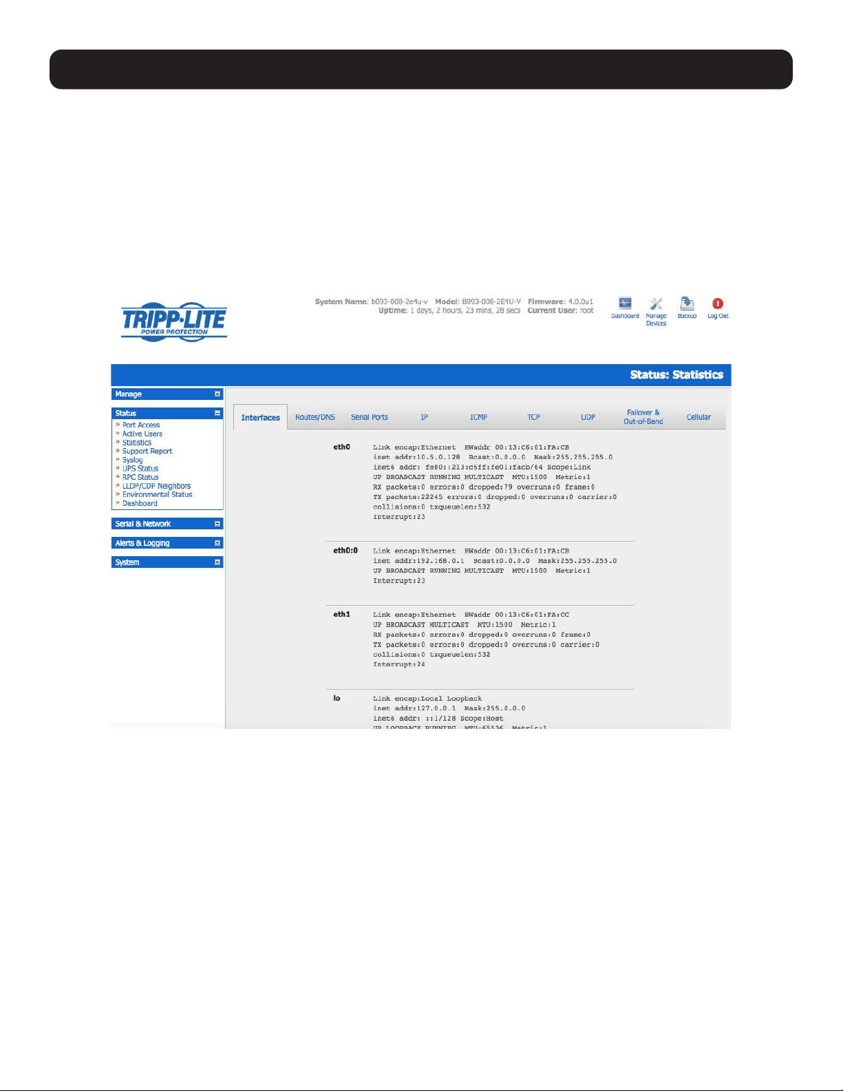
203
12. Status Reports
To allow more detailed control of which users to disconnect, a table at the bottom of the page with a dropdown menu lists
all connected users and connected ports. For example, if you wish to disconnect the user “tester” from all ports, choose
“tester” in the Users box, and All ports in the Ports box, then hit the Disconnect Sessions button.
Note: You can also disconnect serial sessions from the command line using the --disconnect option with the pmusers command.
12.2 Statistics
The Statistics report provides a snapshot of the status, current traffic and other activities and operations of your console
server:
• Select Status: Statistics.
• Detailed statistics reports can be found by selecting from the various submenus.
12.3 Support Reports
The Support Report provides useful status information that will assist the Tripp Lite technical support team to solve any
problems you may experience with your console server.
If you experience a problem and have to contact support, ensure you include the Support Report with your email support
request. The Support Report should be generated when the issue is occurring and attached in plain text format.
• Select Status: Support Report. You will be presented with a status snapshot.
• Save the file as a text file and attach it to your support email.
Note: For console servers running firmware version 3.11 and above and for devices where the serial number can be retrieved, there is now
a Feature Set section in the support report where the serial number is among the information displayed. For devices not supporting this
feature, there is no change to the support report.
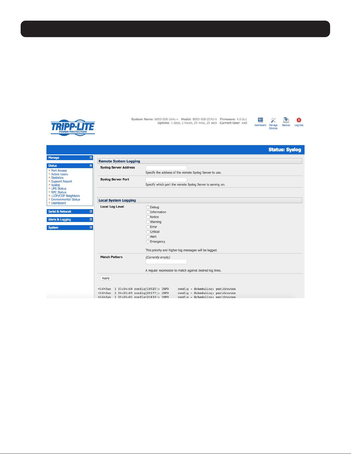
204
12. Status Reports
12.4 Syslog
The Linux System Logger in the console server maintains a record of all system messages and errors:
• Select Status: Syslog.
The syslog record can be redirected to a remote Syslog Server:
• Enter the remote Syslog Server Address and Syslog Server Port details. Click Apply.
The console maintains a local syslog. To view the local syslog file:
• Select Status: Syslog.
To make it easier to find information in the local syslog file, a pattern-matching filter tool is provided.
• Specify the Match Pattern to be searched for and click Apply. The syslog will then be represented with only those entries
that actually include the specified pattern.
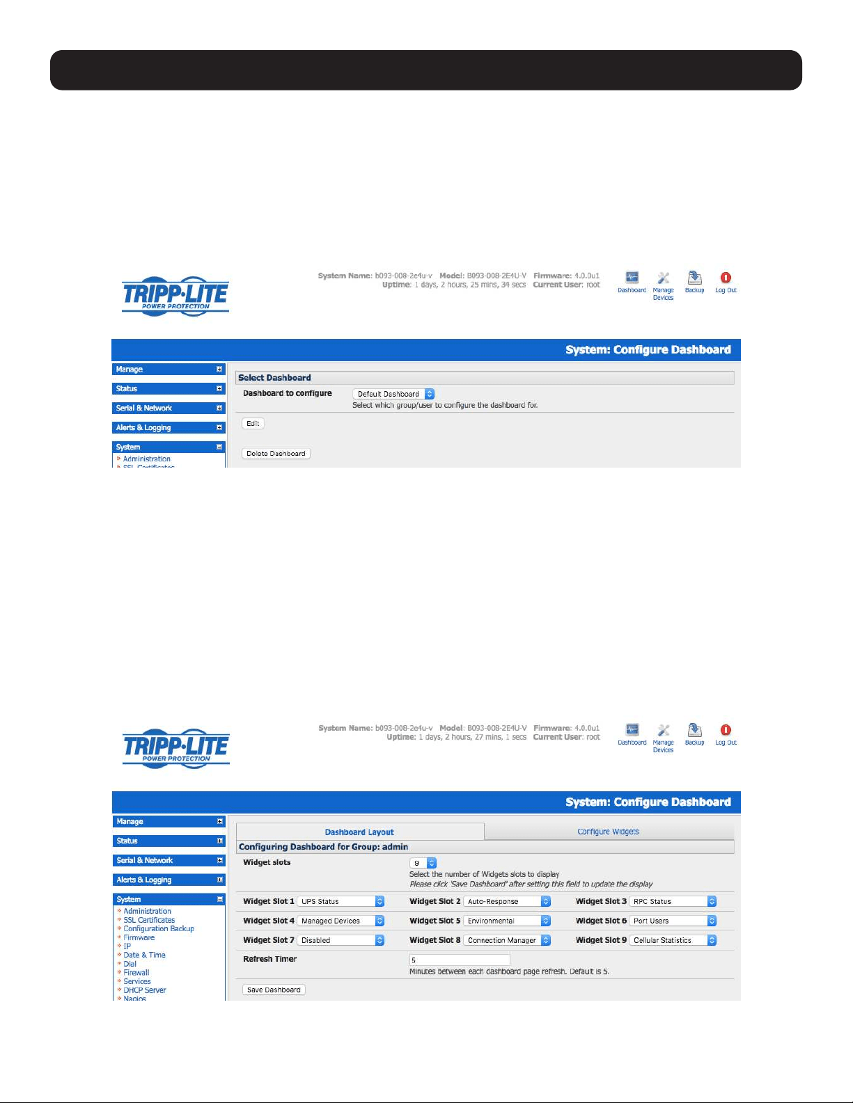
205
12.5 Dashboard
The Dashboard provides the Administrator with a summary of the status of the console server and its managed devices.
Custom dashboards can be configured for each user group.
12.5.1 Configuring the Dashboard
Only users in the admin group (and the root user) can configure and access the dashboard. To configure a custom dashboard:
• Select System: Configure Dashboard and select the user (or group) for whom to configure this custom dashboard layout.
Note: You can configure a custom dashboard for any admin user or for the admin group, or you can reconfigure the default dashboard
The Status: Dashboard screen is the first screen displayed when admin users (other than root) log into the console manager. For example,
if you log in as “John” and John is member of the admin group, a dashboard layout will be configured for John that you can view upon log-in
and each time you click on the Status: Dashboard menu item.
If there is no dashboard layout configured for John, but an admin group dashboard is configured, you will see the admin group dashboard
instead. If there is no user dashboard or admin group dashboard configured, you will see the default dashboard.
The root user does not have its own dashboard.
The above configuration options are intended to enable admin users to set up their own custom dashboards.
The dashboard displays a configurable number of widgets. These widgets include status for major subsystems such as conma,
Auto-Response, Managed Devices and cellular. The admin user can configure which widgets are to be displayed and where:
• Go to the Dashboard layout panel and select which widget is to be displayed in each of the Widget Slots.
• Click Apply.
12. Status Reports
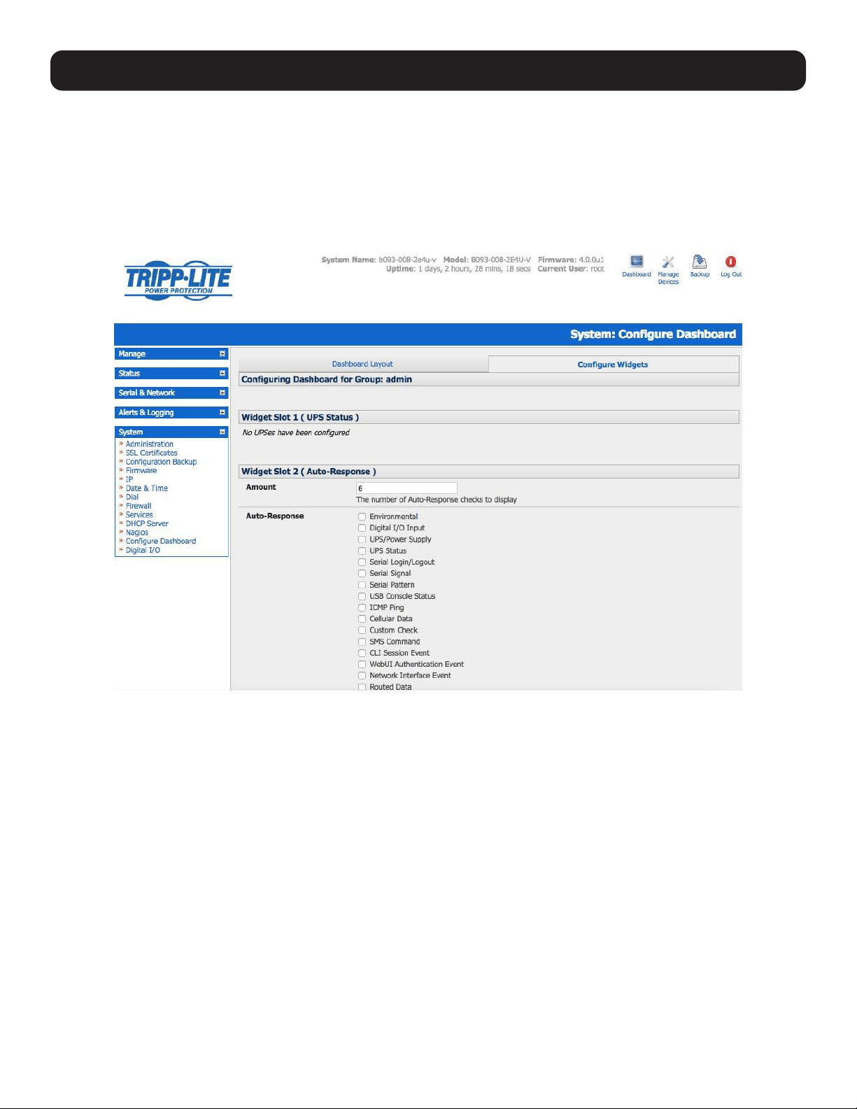
206
12. Status Reports
Note: The Alerts widget is a new screen that shows the current alerts status. When an alert is triggered, a corresponding .XML file is created
in /var/run/alerts/. The dashboard scans all of these files and displays a summary status in the alerts widget. When an alert is deleted, the
corresponding .XML files belonging to that alert are also deleted.
To configure what is to be displayed by each widget:
• Go to the Configure widgets panel and configure each selected widget (e.g., specify which UPS status is to be displayed on
the ups widget or the maximum number of managed devices to be displayed in the devices widget.
• Click Apply.
Note: Dashboard configuration is stored in the /etc/config/config.xml file. Each configured dashboard will increase the config file. If this file
gets too big, you can run out of memory space on the console server.

207
12.5.2 Creating Custom Widgets for the Dashboard
To run a custom script inside a dashboard widget:
Create a file called widget-<name>.sh in the folder /etc/config/scripts / , where <name> can be of your choosing. You can
have as many custom dashboard files as desired.
Inside this file, you can use any code you wish. When configuring the dashboard, choose widget-<name>.sh in the
dropdown list. The dashboard will run the script and display the output of the script commands inside the specific widget.
The best way to format the output is to send HTML commands back to the browser by adding echo commands in the script:
echo ‘<table>’
You can run any command and its output will display in the widget window directly.
Below is an example script writing the current date to a file and echoing HTML code back to the browser. The HTML code gets
an image from a specific URL and displays it in the widget.
#!/bin/sh
date >> /tmp/test
echo ‘<table>’
echo ‘<tr><td> This is my custom script running </td></tr>’
echo ‘<tr><td>’
echo ‘<img src=”http://www.vinras.com/images/linux-online-inc.jpg”>’
echo ‘</td></tr>’
echo ‘</table>’
exit 0
12. Status Reports
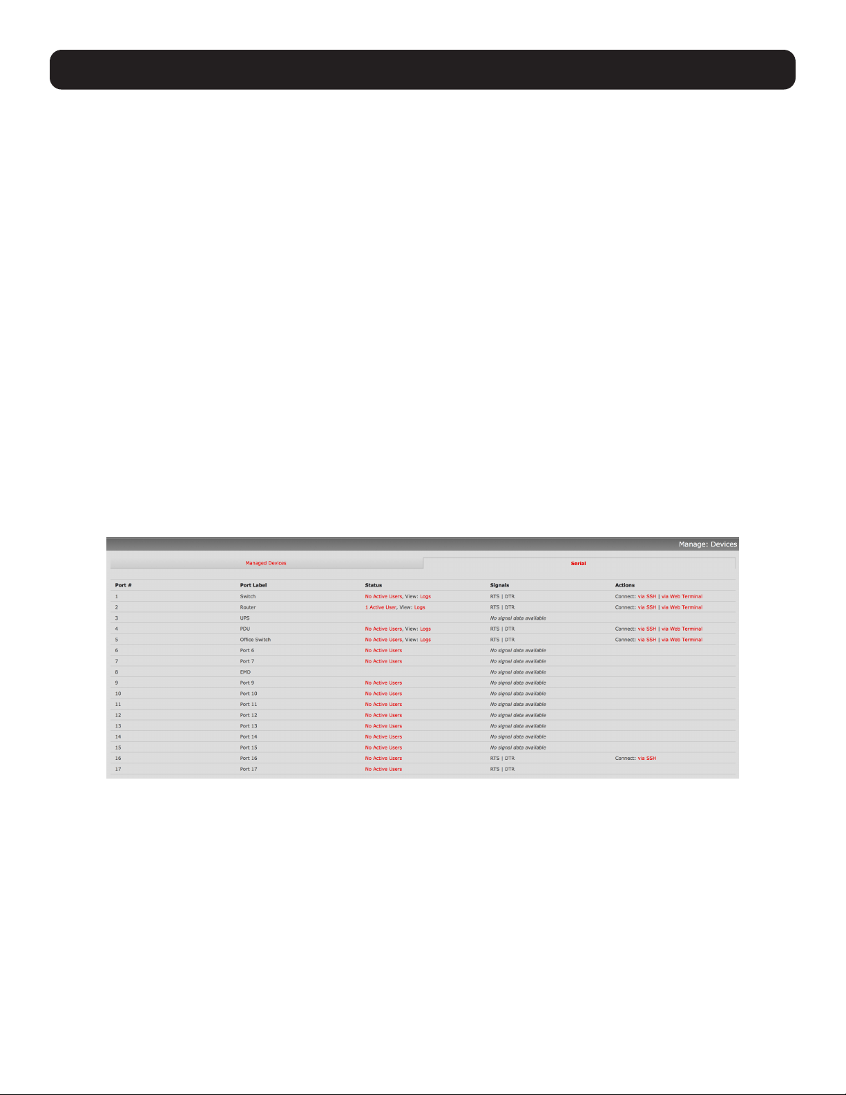
208
13. Management
The console server has a small number of Manage reports and tools available to both Administrators and Users:
• Access and control authorized devices
• View serial port logs and host logs for those devices
• Use SSH or Web Terminal to access serially attached consoles
• Control power devices (where authorized)
All other management console menu items are available to Administrators only.
13.1 Device Management
Note: The manage devices UI has received substantial updates in firmware version 3.12.
To display managed devices and their grouped serial, network and power connections:
• Select Manage: Devices or click the Manage Devices icon in the top right of the UI.
• Admin-group users are presented with a list of all configured managed devices and their constituent connections. User-group
users only see the managed devices where they have been explicitly permitted access.
• The Status column displays the current status for each related connection (e.g., active users for serial connections and
power status for RPC outlet connections) with links to detailed status.
• The links in the Actions column are used to control the managed device (e.g., connect to a console session or power cycle
– power actions are not performed until the action has been confirmed via pop-up message).
• The Administrator will be presented with a list of all configured managed devices, whereas the User will only see the
managed devices they (or their Group) have been given access privileges for.
• Alternately, select the Serial tab for an ungrouped view of permitted serial port connections for the current user.
• An additional Signals column displays the current state of the serial pins.
Note: To use the Connect: via SSH links, your computer’s operating system must recognize the ssh:/ / URI scheme and have a protocol
handler configured (e.g., an SSH client like SecureCRT).
13.2 Port and Host Logs
Administrators and Users can view and download logs of data transferred to and from connected devices.
• Select Manage: Port Logs and the serial port number to be displayed.
• To display host logs, select Manage: Host Logs and the host to be displayed.
This will display logs stored locally on the console server memory or USB flash memory.
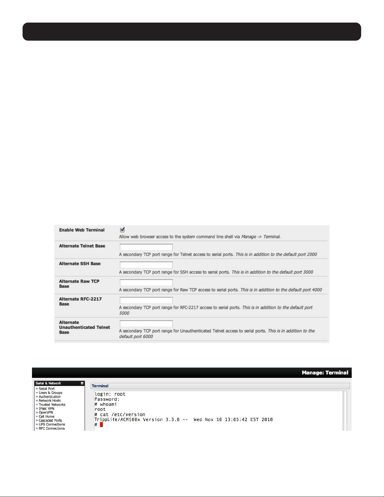
209
13. Management
13.3 Terminal Connection
There are two methods available for accessing the console server command line and devices attached to the console server
serial ports directly from a web browser:
• The web terminal service uses AJAX to enable the web browser to connect to the console server using HTTP or HTTPS as a
terminal, without the need for additional client installation on the user’s PC.
• The SDT Connector service launches a pre-installed SDT Connector client on the user’s PC to establish secure SSH access,
then uses pre-installed client software on the client PC to connect to the console server.
Web browser access is available to users who are a member of the admin or users groups.
13.3.1 Web Terminal
The AJAX-based web terminal service may be used to access the console server command line or attached serial devices.
Note: Any communication using the web terminal service with HTTP is unencrypted and not secure. The web terminal connects to the
command line or serial device using the same protocol being used to browse the Tripp Lite management console, i.e. if you are browsing
using an https:/ / URL (this is the default), the web terminal connects using HTTPS.
13.3.1.1 Web Terminal to Command Line
To enable the web terminal service for the console server:
• Select System: Firewall.
• Check Enable Web Terminal, then click Apply.
Administrators can now communicate directly with the console server command line from their browser:
• Select Manage: Terminal to display the web terminal from which you can log in to the console server command line.
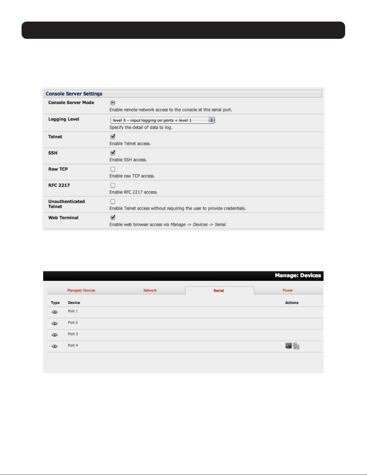
210
13. Management
13.3.1.2 Web Terminal to Serial Device
To enable the web terminal service for each serial port you want to access:
• Select Serial & Network: Serial Port and click Edit. Ensure the serial port is in Console Server Mode.
• Check Web Terminal and click Apply.
Administrator and Users can communicate directly with serial port attached devices from their browser:
• Select the Serial tab on the Manage: Devices menu.
• Under the Action column, click the Web Terminal icon to display the web terminal connected directly to the attached serial
device.
Note: The web terminal feature was introduced in firmware version 3.3. Earlier releases had an open source jcterm java terminal applet,
which and be downloaded to your browser to connect to the console server and attached serial port devices. However, jcterm is known to
have JRE compatibility issues and is no longer supported.
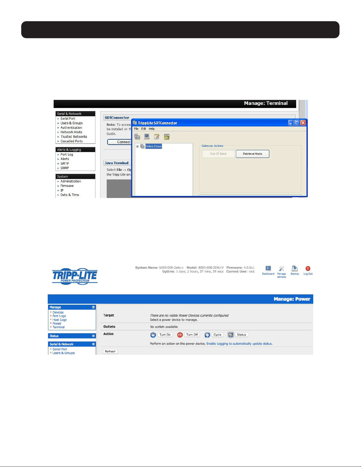
211
13. Management
13.3.2 SDT Connector Access
Administrator and Users can communicate directly with the console server command line and devices attached to the console
server serial ports using SDT Connector and their local tenet client, or using a Web terminal and browser.
• Select Manage: Terminal.
• Click Connect to SDT Connector. This will activate the SDT Connector client on the computer and load your local telnet
client to connect to the command line or serial port using SSH.
Note: SDT Connector must be installed on the computer you are using. The console server must also be added as a gateway (refer to 6.
SSH Tunnels and SDT Connector).
13.4 Power Management
Administrators and Users can access and manage the connected power devices.
• Select Manage: Power. This enables the user to power Off/On/Cycle any power outlet on any PDU the user has been given
access privileges to (refer to 8. Power, Management and Digital I/O).

212
14. Configuration from the Command Line
For those who prefer to configure their console server at the Linux command line level (rather than use a browser and the
management console), this chapter describes using command line access and the config tool to manage the console server
and configure the ports.
When displaying a command, this chapter uses single quotes (‘’) for user defined values (e.g., descriptions and names).
Element values without single quotes must be typed exactly as shown.
14.1 Accessing Config from the Command Line
The console server runs a standard Linux kernel and embeds a suite of open source applications. If you do not want to use a
browser and the management console tools, you can configure the console server and manage connected devices from the
command line using standard Linux and Busybox commands as well as applications like ifconfig, gettyd, stty, powerman,
NUT, etc. However, without careful management, these settings may not withstand a power-cycle-reset or reconfiguration.
Tripp Lite provides a number of custom command line utilities and scripts that easily configure the console server and ensure
changes are stored in the console server’s flash memory.
The config utility allows manipulation of the system configuration from the command line. With config, a new configuration can
be activated by running the relevant configurator, which performs the action necessary to make the configuration changes live.
To access config from the command line:
• Power up the console server and connect the “terminal” device:
o If connecting using the serial line, plug a serial cable between the console server’s local DB-9 console port and the
terminal device. Configure the serial connection of the terminal device you are using to 115200bps, 8 data bits, no parity
and one stop bit.
o If you are connecting over LAN, you will need to interconnect the Ethernet ports and direct your terminal emulator program
to the IP address of the console server (192.168.0.1 by default).
• Log on to the console server by pressing return a few times. The console server will request a username and password. Enter
the username root and the password default. The command line prompt should appear as a hash (#).
This section is not intended to teach you Linux. In following these instructions, we assume you already
have a certain level of understanding before executing Linux kernel level commands.
The config tool
Syntax
config [ -ahv ] [ -d id ] [ -g id ] [ -p path ] [ -r configurator ] [ -s id=value ] [ -P id ]
Description
The config tool is designed to perform multiple actions from one command so options can be chained together.
The config tool allows manipulation and querying of the system configuration from the command line. Using config, the
new configuration can be activated by running the relevant configurator, which performs the necessary action to apply the
configuration changes in real-time.
The custom user configuration is saved in the /etc/config/config.xml file. This file is transparently accessed and edited when
configuring the device using the management console browser GUI. Only the user ‘root’ can configure from the shell.
By default, the config elements are separated by a ‘.’ character. The root of the config tree is <config>. To address a specific
element, place a ‘.’ between each node/branch. To access and display the description of user1, type:
# config -g config.users.user1.description
The root node of the config tree is <config>. To display the entire config tree, type:
# config -g config
To display the help text for the config command, type:
# config -h

213
14. Configuration from the Command Line
The config application resides in the /bin directory. The environmental variable PATH contains a route to the /bin directory.
This allows a user to simply type config at the command prompt instead of the full path /bin/config.
Options
-a –run-all Run all registered configurators. This performs every configuration synchronization action pushing all
changes to the live system.
-h –help Display a brief usage message.
-v –verbose Log extra debug information.
-d –del=id Remove the given configuration element specified by a ‘.’ separated identifier.
-g –get=id Display the value of a configuration element.
-p –path=file Specify an alternate configuration file to use. The default file is located at /etc/config/config.xml.
-r –run=configurator Run the specified registered configurator. Registered configurators are listed below.
-s --set=id=value Change the value of configuration element specified by a ‘.’ separated identifier.
-e --export=file Save active configuration to file.
-i --import=file Load configuration from file.
-t --test-import=file Pretend to load configuration from file.
-S --separator=char The pattern to separate fields with, default is ‘.’
-P --password=id Prompt user for a value. Hash the value, and then save.
The registered configurators are:
alerts ipconfig
auth nagios
cascade power
console serialconfig
dhcp services
dialin Secondary
eventlog systemsettings
hosts time
ipaccess ups
users
There are three ways to delete a config element value. The simplest way is use the delete-node script detailed in 15.
Advanced Configuration. You can also assign the config element to “”, or delete the entire config node using -d:
# /bin/config -d ‘element name’
All passwords are saved in plaintext except the user passwords and system passwords, which are encrypted.
Note: The config command does not verify whether the nodes edited/added by the user are valid. As such, any node may be added to the
tree. For example, if a user were to run the following command:
# /bin/config -s config.fruit.apple=sweet
the configurator will not verify, though this command is clearly useless. When the configurators are run to turn the config.xml file into live
config, they will simply ignore this <fruit> node. Administrators must make sure of the spelling when typing config commands. Incorrect
spelling for a node will not be flagged.
Most configurations made to the XML file will be immediately active. To ensure all configuration changes are active, especially
when editing user passwords, run all the configurators:
# /bin/config -a
For information on backing up and restoring the configuration file, refer to 15. Advanced Configuration.

214
14. Configuration from the Command Line
14.1.1 Serial Port Configuration
RS-232 common settings are the first set of configurations to be made to any serial port. For example, to set up serial port 5,
use the following properties:
Baud Rate 9600
Parity None
Data Bits 8
Stop Bits 1
label Myport
log level 0
protocol RS232
flow control None
Use the following commands:
# config -s config.ports.port5.speed=9600
# config -s config.ports.port5.parity=None
# config -s config.ports.port5.charsize=8
# config -s config.ports.port5.stop=1
# config -s config.ports.port5.label=myport
# config -s config.ports.port5.loglevel=0
# config -s config.ports.port5.protocol=RS232
# config -s config.ports.port5.flowcontrol=None
The following command will synchronize the live system with the new configuration:
# config -r serialconfig
Note: Supported serial port baud-rates are ‘50’, ‘75’, ‘110’, ‘134’, ‘150’, ‘200’, ‘300’, ‘600’,
‘1200’, ‘1800’, ‘2400’, ‘4800’, ‘9600’, ‘19200’, ‘38400’, ‘57600’, ‘115200’, and ‘230400’.
Supported parity values are ‘None’, ‘Odd’, ‘Even’, ‘Mark’ and ‘Space’.
Supported data-bits values are ‘8’, ‘7’, ‘6’ and ‘5’.
Supported stop-bits values are ‘1’, ‘1.5’ and ‘2’.
Supported flow-control values are ‘Hardware’, ‘Software’ and ‘None’.
Additionally, before any port can function properly, the port mode needs to be set. Any port can be set to run in one of the five
possible modes: [Console Server mode | Device mode | SDT mode | Terminal server mode | Serial bridge mode]. All these
modes are mutually exclusive. Refer to 4. Serial Port, Host, Device and User Configuration for details.
Console Server Mode
The command to set the port in portmanager mode:
# config -s config.ports.port5.mode=portmanager
To set the following optional config elements for this mode:
Data accumulation period 100 ms
Escape character % (default is ~)
log level 2 (default is 0)
Shell power command menu Enabled
RFC2217 access Enabled
Limit port to 1 connection Enabled
SSH access Enabled
TCP access Enabled
telnet access Disabled
Unauthorized telnet access Disabled
# config -s config.ports.port5.delay=100
# config -s config.ports.port5.escapechar=%
# config -s config.ports.port5.loglevel=2
# config -s config.ports.port5.powermenu=on
# config -s config.ports.port5.rfc2217=on
# config -s config.ports.port5.singleconn=on
# config -s config.ports.port5.ssh=on
# config -s config.ports.port5.tcp=on
# config -d config.ports.port5.telnet
# config -d config.ports.port5.unauthtel

215
Device Mode
For a device mode port, set the port type to either ups, rpc, or enviro:
# config -s config.ports.port5.device.type=[ups | rpc | enviro]
For port 5 as a UPS port:
# config -s config.ports.port5.mode=reserved
For port 5 as an RPC port:
# config -s config.ports.port5.mode=powerman
For port 5 as an Environmental port:
# config -s config.ports.port5.mode=reserved
SDT Mode
To enable access over SSH to a host connected to serial port 5:
# config -s config.ports.port5.mode=sdt
# config -s config.ports.port5.sdt.ssh=on
To configure a username and password when accessing this port with Username = user1 and Password = secret:
# config -s config.ports.port#.sdt.username=user1
# config -s config.ports.port#.sdt.password=secret
Terminal Server Mode
Enable a TTY login for a local terminal attached to serial port 5:
# config -s config.ports.port5.mode=terminal
# config -s config.ports.port5.terminal=[vt220 | vt102 | vt100 | linux | ansi]
The default terminal is vt220.
Serial Bridge Mode
Create a network connection to a remote serial port via RFC-2217 on port 5:
# config -s config.ports.port5.mode=bridge
Optional configurations for the network address of RFC-2217 server of 192.168.3.3 and TCP port used by the RFC-2217
service = 2500:
# config -s config.ports.port5.bridge.address=192.168.3.3
# config -s config.ports.port5.bridge.port=2500
To enable RFC-2217 access: # config -s config.ports.port5.bridge.rfc2217=on
To redirect the serial bridge over an SSH tunnel to the server: # config -s config.ports.port5.bridge.ssh.enabled=on
14. Configuration from the Command Line

216
14. Configuration from the Command Line
Syslog settings
Additionally, the global system log settings can be set for any specific port, in any mode:
# config -s config.ports.port#.syslog.facility=’facility’
‘facility’ can be:
Default
local 0-7
auth
authpriv
cron
daemon
ftp
kern
lpr
mail
news
user
uucp
# config -s config.ports.port#.syslog.priority=’priority’
‘priority’ can be:
Default
warning
notice
Info
error
emergency
debug
critical
alert
14.1.2 Adding and Removing Users
First, determine the total number of existing Users (if you have no existing Users, you can assume this is 0):
# config -g config.users.total
This command should display config.users.total 1. If you see config.users.total , this means you have 0 Users configured.
Your new User will be the existing total, plus 1. For example, if the previous command is 0, then start with user number 1. If
you already have 1 User, your new User will be number 2, etc.
To add a user (with Username=John, Password=secret and Description=mySecondUser), issue the commands:
# config -s config.users.total=2 (assuming we already have 1 user configured)
# config -s config.users.user2.username=John
# config -s config.users.user2.description=mySecondUser
# config -P config.users.user2.password
Note: The -P parameter will prompt the user for a password and encrypt it. In fact, the value of any config element can be encrypted using
the -P parameter, but only encrypted user passwords and system passwords are supported. If any other element value were to be encrypted,
the value will become inaccessible and have to be reset.
To add this user to specific groups (admin/users):
# config -s config.users.user2.groups.group1=’groupname’
# config -s config.users.user2.groups.group2=’groupname2’
etc...
To give this user access to a specific port:
# config -s config.users.user2.port1=on
# config -s config.users.user2.port2=on
# config -s config.users.user2.port5=on
etc...

217
14. Configuration from the Command Line
To remove port access:
# config -s config.users.user2.port1=’’ (the value is left blank)
or simply:
# config -d config.users.user2.port1
The port number can be anything from 1 to 48, depending on the available ports on the specific console server.
For example, assume we have an RPC device connected to port 1 on the console server and the RPC is configured. To allow
this user access to RPC outlet number 3 on the RPC device, run the commands below:
# config -s config.ports.port1.power.outlet3.users.user2=John
# config -s config.ports.port1.power.outlet3.users.total=2 (total number of users that have access to this outlet)
If more users are allowed access to this power outlet, increment the ‘config.ports.port1.power.outlet3.users.total’ element
accordingly.
To allow this user access to network host 5 (assuming the host is configured):
# config -s config.sdt.hosts.host5.users.user1=John
# config -s config.sdt.hosts.host5.users.total=1 (total number of users having access to host)
To allow another user named ‘Peter’ access to the same host:
# config -s config.sdt.hosts.host5.users.user2=Peter
# config -s config.sdt.hosts.host5.users.total=2 (total number of users having access to host)
To edit any of the user element values, use the same approach as when adding user elements (i.e. use the ‘-s’ parameter). If
any of the config elements do not exist, they will automatically be created.
To delete the user called John, use the delete-node script:
# ./delete-node config.users.user2
The following command will synchronize the live system with the new configuration:
# config -r users
14.1.3 Adding and Removing User Groups
The console server is configured with a few default user groups (though only two of these groups are visible in the
management console GUI). To determine how many groups are already present:
# config -g config.groups.total
Assume this value is six. Make sure to number any new groups you create from seven onwards.
To add a custom group to the configuration with Group name=Group7, Group description=MyGroup and Port access= 1,5 ,
issue the commands:
# config -s config.groups.group7.name=Group7
# config -s config.groups.group7.description=MyGroup
# config -s config.groups.total=7
# config -s config.groups.group7.port1=on
# config -s config.groups.group7.port5=on
Assume an RPC device is connected to port 1 on the console manager and the RPC is configured. To allow this group access
to RPC outlet number 3 on the RPC device, run the two commands below:
# config -s config.ports.port1.power.outlet3.groups.group1=Group7
# config -s config.ports.port1.power.outlet3.groups.total=1 (total number of groups that have access to this outlet)
If more groups are allowed access to this power outlet, increment the ‘config.ports.port1.power.outlet3.groups.total’
element accordingly.
To allow this group access to network host 5:
# config -s config.sdt.hosts.host5.groups.group1=Group7
# config -s config.sdt.hosts.host5.groups.total=1 (total number of groups having access to host)

218
14. Configuration from the Command Line
To allow another group named ‘Group8’ access to the same host:
# config -s config.sdt.hosts.host5.groups.group2=Group8
# config -s config.sdt.hosts.host5.groups.total=2 (total number of users having access to host)
To delete the Group7, use the following command:
# rmuser Group7
Attention: The rmuser script is a generic script to remove any config element from config.xml correctly. However,
any dependencies or references to this group will not be affected. Only the group details are deleted. The
administrator is responsible for reviewing config.xml and removing group dependencies and references manually,
specifically if the group had access to a host or RPC device.
The following command will synchronize the live system with the new configuration:
# config -a
14.1.4 Authentication
To change the type of authentication for the console server:
# config -s config.auth.type=’authtype’
‘authtype’ can be:
Local
LocalTACACS
TACACS
TACACSLocal
TACACSDownLocal
LocalRADIUS
RADIUS
RADIUSLocal
RADIUSDownLocal
LocalLDAP
LDAP
LDAPLocal
LDAPDownLocal
To configure TACACS authentication:
# config -s config.auth.tacacs.auth_server=’comma separated list’ (list of remote authentication and authorization servers.)
# config -s config.auth.tacacs.acct_server=’comma separated list’ (list of remote accounting servers. If unset, Authentication and
Authorization Server Address will be used.)
# config -s config.auth.tacacs.password=’password’
To configure RADIUS authentication:
# config -s config.auth.radius.auth_server=’comma separated list’ (list of remote authentication and authorization servers.)
# config -s config.auth.radius.acct_server=’comma separated list’ (list of remote accounting servers. If unset, Authentication and
Authorization Server Address will be used.)
# config -s config.auth.radius.password=’password’
To configure LDAP authentication:
# config -s config.auth.ldap.server=’comma separated list’ (list of remote servers.)
# config -s config.auth.ldap.basedn=’name’ (The distinguished name of the search base. For example: dc=my-company,dc=com)
# config -s config.auth.ldap.binddn=’name’ (The distinguished name to bind to the server with. The default is to bind anonymously.)
# config -s config.auth.radius.password=’password’
The following command will synchronize the live system with the new configuration:
# config -r auth

219
14. Configuration from the Command Line
14.1.5 Network Hosts
To determine the total number of currently configured hosts:
# config -g config.sdt.hosts.total
Assume this value is equal to 3. If you add another host, make sure to increment the total number of hosts from 3 to 4:
# config -s config.sdt.hosts.total=4
If the output is config.sdt.hosts.total , assume 0 hosts are configured.
Add Power Device Host
To add a UPS/RPC network host with the following details:
IP address / DNS name 192.168.2.5
Host name remoteUPS
Description UPSroom3
Type UPS
Allowed services ssh port 22 and https port 443
Log level for services 0
Issue the commands below:
# config -s config.sdt.hosts.host4.address=192.168.2.5
# config -s config.sdt.hosts.host4.name=remoteUPS
# config -s config.sdt.hosts.host4.description=UPSroom3
# config -s config.sdt.hosts.host4.device.type=ups
# config -s config.sdt.hosts.host4.tcpports.tcpport1=22
# config -s config.sdt.hosts.host4.tcpports.tcpport1.loglevel=0
# config -s config.sdt.hosts.host4.udpports.udpport2=443
# config -s config.sdt.hosts.host4.udpports.udpport2.loglevel=0
The loglevel can have a value of 0 or 1.
The default services that should be configured are: 22/tcp (ssh), 23/tcp (telnet), 80/tcp (http), 443/tcp (https), 1494/tcp
(ica), 3389/tcp (rdp), 5900/tcp (vnc)
Add Other Network Host
To add any other type of network host with the following details:
IP address / DNS name 192.168.3.10
Host name OfficePC
Description MyPC
Allowed services ssh port 22,https port 443
log level for services 1
Issue the commands below. If the host is not a PDU or UPS power device, or a server with IPMI power control, leave the device
type blank:
# config -s config.sdt.hosts.host4.address=192.168.3.10
# config -s config.sdt.hosts.host4.description=MyPC
# config -s config.sdt.hosts.host4.name=OfficePC
# config -s config.sdt.hosts.host4.device.type=’’ (leave this value blank)
# config -s config.sdt.hosts.host4.tcpports.tcpport1=22
# config -s config.sdt.hosts.host4.tcpports.tcpport1.loglevel=1
# config -s config.sdt.hosts.host4.udpports.tcppport2=443
# config -s config.sdt.hosts.host4.udpports.tcpport2.loglevel=1
To add the new host as a managed device, make sure to use the current total number of managed devices + 1, for the new
device number.
To get the current number of managed devices:
# config -g config.devices.total

220
14. Configuration from the Command Line
Assuming we already have one managed device, our new device will be device 2. Issue the following commands:
# config -s config. devices.device2.connections.connection1.name=192.168.3.10
# config -s config. devices.device2.connections.connection1.type=Host
# config -s config. devices.device2.name=OfficePC
# config -s config. devices.device2.description=MyPC
# config -s config.devices.total=2
The following command will synchronize the live system with the new configuration:
# config -hosts
14.1.6 Trusted Networks
You can further restrict remote access to serial ports based on the source IP address. To configure this via the command line,
do the following:
Determine the total number of existing trusted network rules. If you have no existing rules, assume this is 0.
# config -g config.portaccess.total
This command should display config.portaccess.total 1.
If you see config.portaccess.total , you have 0 rules configured.
Your new rule will be the existing total, plus 1. For example, if the previous command gave you 0, you start with rule number 1.
If you already have rule 1, your new rule will be number 2, etc.
To restrict access to serial port 5 to computers from a single class C network (e.g., 192.168.5.0), issue the following
commands (assuming you have a previous rule in place).
Add a trusted network:
# config -s config.portaccess.rule2.address=192.168.5.0
# config -s “config.portaccess.rule2.description=foo bar”
# config -s config.portaccess.rule2.netmask=255.255.255.0
# config -s config.portaccess.rule2.port5=on
# config -s config.portaccess.total=2
The following command will synchronize the live system with the new configuration:
# config -r serialconfig
14.1.7 Cascaded Ports
To add a new Secondary device with the following settings:
IP address/DNS name 192.168.0.153
Description CM in office 42
Label b098-16
Number of ports 16
The following commands must be issued:
# config -s config.cascade.Secondarys.Secondary1.address=192.168.0.153
# config -s “config.cascade.Secondarys.Secondary1.description=B098-16 in office 42”
# config -s config.cascade.Secondarys.Secondary1.label=b098-16
# config -s config.cascade.Secondarys.Secondary1.ports=16
The total number of Secondary devices must also be incremented. If this is the first Secondary device being added, type:
# config -s config.cascade.Secondarys.total=1
Increment this value when adding more Secondary devices.
Note: If a Secondary device is added using the CLI, the Primary SSH public key will need to be manually copied to every Secondary device
before cascaded ports will work. Refer to 4. Serial Port, Host, Device and User Configuration.
The following command will synchronize the live system with the new configuration:
# config -r cascade

221
14.1.8 UPS Connections
Managed UPS Systems
Before adding a managed UPS, make sure at least one port has been configured to run in ‘device mode’, and that the device
is set to ‘ups’.
To add a managed UPS with the following values:
Connected via Port 1
UPS name My UPS
Description UPS in room 5
Username to connect to UPS User2
Password to connect to UPS secret
Shutdown order 2 (0 shuts down first)
Driver genericups
Driver option - option option
Driver option - argument argument
Logging Enabled
Log interval 2 minutes
Run script when power is critical Enabled
# config -s config.ups.monitors.monitor1.port=/dev/port01
If the port number is higher than 9, eg port 13, enter:
# config -s config.ups.monitors.monitor1.port=/dev/port13
# config -s “config.ups.monitors.monitor1.name=My UPS”
# config -s “config.ups.monitors.monitor1.description=UPS in room 5”
# config -s config.ups.monitors.monitor1.username=User2
# config -s config.ups.monitors.monitor1.password=secret
# config -s config.ups.monitors.monitor1.sdorder=2
# config -s config.ups.monitors.monitor1.driver=genericups
# config -s config.ups.monitors.monitor1.options.option1.opt=option
# config -s config.ups.monitors.monitor1.options.option1.arg=argument
# config -s config.ups.monitors.monitor1.options.total=1
# config -s config.ups.monitors.monitor1.log.enabled=on
# config -s config.ups.monitors.monitor1.log.interval=2
# config -s config.ups.monitors.monitor1.script.enabled=on
Make sure to increment the total monitors:
# config -s config.ups.monitors.total=1
The five commands below will add the UPS to ‘Managed devices. Assuming there are already two managed devices configured:
# config -s “config.devices.device3.connections.connection1.name=My UPS”
# config -s “config.devices.device3.connections.connection1.type=UPS Unit”
# config -s “config.devices.device3.name=My UPS”
# config -s “config.devices.device3.description=UPS in toom 5”
# config -s config.devices.total=3
To delete this managed UPS:
# config -d config.ups.monitors.monitor1
Decrement monitors.total when deleting a managed UPS
14. Configuration from the Command Line

222
14. Configuration from the Command Line
Remote UPS Systems
To add a remote UPS with the following details (assuming this is your first remote UPS):
UPS name oldUPS
Description UPS in room 2
Address 192.168.50.50
Log status Disabled
Log rate 240 seconds
Run shutdown script Enabled
# config -s config.ups.remotes.remote1.name=oldUPS
# config -s “config.ups.remotes.remote1.description=UPS in room 2”
# config -s config.ups.remotes.remote1.address=192.168.50.50
# config -d config.ups.remotes.remote1.log.enabled
# config -s config.ups.remotes.remote1.log.interval=240
# config -s config.ups.remotes.remote1.script.enabled=on
# config -s config.ups.remotes.total=1
The following command will synchronize the live system with the new configuration:
# config -a
14.1.9 RPC Connections
You can add an RPC connection from the command line, but it is not recommended to do so because of dependency issues.
Before adding an RPC, the management console GUI code ensures at least 1 port has been configured to run in ‘device
mode’, and that the device is set to ‘rpc’.
To add an RPC with the following values:
RPC type TL PDUMV20NETLX
Connected via Port 2
UPS name MyRPC
Description RPC in room 5
Login name for device rpclogin
Login password for device secret
SNMP community v1 or v2c
Logging Enabled
Log interval 600 second
Number of power outlets (depends on the type/model of the RPC)
# config -s config.ports.port2.power.type=TL PDUMV20NETLX
# config -s config.ports.port2.power.name=MyRPC
# config -s “config.ports.port2.power.description=RPC in room 5”
# config -s config.ports.port2.power.username=rpclogin
# config -s config.ports.port2.power.password=secret
# config -s config.ports.port2.power.snmp.community=v1
# config -s config.ports.port2.power.log.enabled=on
# config -s config.ports.port2.power.log.interval=600
# config -s config.ports.port2.power.outlets=4
The following five commands are used by the management console to add the RPC to ‘Managed Devices’:
# config -s config.devices.device3.connections.connection1.name=myRPC
# config -s “config.devices.device3.connections.connection1.type=RPC Unit”
# config -s config.devices.device3.name=myRPC
# config -s “config.devices.device3.description=RPC in room 5”
# config -s config.devices.total=3
The following command will synchronize the live system with the new configuration:
# config -a

223
14. Configuration from the Command Line
14.1.10 Environmental
To configure an environmental monitor with the following details:
Monitor name Envi4
Monitor Description Monitor in room 5
Temperature offset 2
Humidity offset 5
Enable alarm 1 ? yes
Alarm 1 label door alarm
Enable alarm 2 ? yes
Alarm 2 label window alarm
Logging enabled ? yes
Log interval 120 seconds
# config -s config.ports.port3.enviro.name=Envi4
# config -s “config.ports.port3.enviro.description=Monitor in room 5”
# config -s config.ports.port3.enviro.offsets.temp=2
# config -s config.ports.port3.enviro.offsets.humid=5
# config -s config.ports.port3.enviro.alarms.alarm1.alarmstate=on
# config -s config.ports.port3.enviro.alarms.alarm1.label=door alarm
# config -s config.ports.port3.enviro.alarms.alarm2.alarmstate=on
# config -s config.ports.port3.enviro.alarms.alarm2.label=window alarm
# config -s config.ports.port3.enviro.alarms.total=2
# config -s config.ports.port3.enviro.log.enabled=on
# config -s config.ports.port3.enviro.log.interval=120
It is important to assign alarms.total=2, even if they are off.
The following five commands will add the environmental monitor to ‘Managed devices’:
To get the total number of managed devices:
# config -g config.devices.total
Make sure to use the total + 1 for the new device below:
# config -s config. devices.device5.connections.connection1.name=Envi4
# config -s “config. devices.device5.connections.connection1.type=EMD Unit”
# config -s config. devices.device5.name=Envi4
# config -s “config. devices.device5.description=Monitor in room 5”
# config -s config.devices.total=5
The following command will synchronize the live system with the new configuration:
# config -a
14.1.11 Managed Devices
To add a managed device: (also see UPS, RPC connections and Environmental)
# config -s “config.devices.device8.name=my device”
# config -s “config.devices.device8.description=The eighth device”
# config -s “config.devices.device8.connections.connection1.name=my device”
# config -s config.devices.device8.connections.connection1.type=[serial | Host | UPS | RPC]
# config -s config.devices.total=8 (decrement this value when deleting a managed device)
To delete the above managed device:
# config -d config.devices.device8
The following command will synchronize the live system with the new configuration:
# config -a

224
14. Configuration from the Command Line
14.1.12 Port Log
To configure serial/network port logging:
# config -s config.eventlog.server.address=’remote server ip address’
# config -s config.eventlog.server.logfacility=’facility’
‘facility’ can be:
Daemon
Local 0-7
Authentication
Kernel
User
Syslog
Mail
News
UUCP
# config -s config.eventlog.server.logpriority=’priority’
‘priority’ can be:
Info
Alert
Critical
Debug
Emergency
Error
Notice
Warning
Assume the remote log server needs a username ‘name1’ and password ‘secret’:
# config -s config.eventlog.server.username=name1
# config -s config.eventlog.server.password=secret
To set the remote path as ‘/tripp-lite/logs’ to save logged data:
# config -s config.eventlog.server.path=/ tripp-lite/logs
# config -s config.eventlog.server.type=[none | syslog | nfs | cifs | usb]
If the server type is set to usb, none of the other values need to be set. The mount point for storing on a remote USB device is
/var/run/portmanager/logdir
The following command will synchronize the live system with the new configuration:
# config -a
14.1.13 Alerts
You can add an email, SNMP or NAGIOS alert by following the steps below.
General Settings for All Alerts
Assume this is our second alert, and we want to send alert emails to [email protected] and SMS text messages to peter@
tripplite.com:
# config -s config.alerts.alert2.description=MySecondAlert
# config -s config.alerts.alert2.email=john@ tripplite.com
# config -s config.alerts.alert2.email2=peter@ tripplite.com
To use NAGIOS to notify of this alert:
# config -s config.alerts.alert2.nsca.enabled=on
To use SNMP to notify of this alert:
# config -s config.alerts.alert2.snmp.enabled=on
Increment the total alerts:
# config -s config.alerts.total=2

225
14. Configuration from the Command Line
Below are the specific settings, depending on the type of alert required:
Connection Alert
To trigger an alert when a user connects to serial port 5 or network host 3:
# config -s config.alerts.alert2.host3=’host name’
# config -s config.alerts.alert2.port5=on
# config -s config.alerts.alert2.sensor=temp
# config -s config.alerts.alert2.signal=DSR
# config -s config.alerts.alert2.type=login
Signal Alert
To trigger an alert when a signal changes state on port 1:
# config -s config.alerts.alert2.port1=on
# config -s config.alerts.alert2.sensor=temp
# config -s config.alerts.alert2.signal=[ DSR | DCD | CTS ]
# config -s config.alerts.alert2.type=signal
Pattern Match Alert
To trigger an alert if the regular expression ‘.*0.0% id’ is found in serial port 10’s character stream:
# config -s “config.alerts.alert2.pattern=.*0.0% id”
# config -s config.alerts.alert2.port10=on
# config -s config.alerts.alert2.sensor=temp
# config -s config.alerts.alert2.signal=DSR
# config -s config.alerts.alert2.type=pattern
UPS Power Status Alert
To trigger an alert when myUPS (on localhost) or thatUPS (on remote host 192.168.0.50) power status changes between
on-line, on-battery and low battery:
# config -s config.alerts.alert2.sensor=temp
# config -s config.alerts.alert2.signal=DSR
# config -s config.alerts.alert2.type=ups
# config -s config.alerts.alert2.ups1=myUPS@localhost
# config -s confi[email protected]
Environmental and Power Sensor Alert
# config -s config.alerts.alert2.enviro.high.critical=’critical value’
# config -s config.alerts.alert2.enviro.high.warning=’warning value’
# config -s config.alerts.alert2.enviro.hysteresis=’value’
# config -s config.alerts.alert2.enviro.low.critical=’critical value’
# config -s config.alerts.alert2.enviro.low.warning=’warning value’
# config -s config.alerts.alert2.enviro1=’Enviro sensor name’
# config -s config.alerts.alert2.outlet#=’RPCname’.outlet#
‘alert2.outlet#’ increments sequentially with each added outlet. The second ‘outlet#’ refers to the specific RPC power outlets.
# config -s config.alerts.alert2.rpc#=’RPC name’
# config -s config.alerts.alert2.sensor=[ temp | humid | load | charge]
# config -s config.alerts.alert2.signal=DSR
# config -s config.alerts.alert2.type=enviro
# config -s config.alerts.alert2.ups1=’UPSname@hostname’
Example 1: To configure a temperature sensor alert for a sensor called ‘SensorInRoom42’:
# config -s config.alerts.alert2.sensor=temp
# config -s config.alerts.alert2.enviro.high.critical=60
# config -s config.alerts.alert2.enviro.high.warning=50
# config -s config.alerts.alert2.enviro.hysteresis=2
# config -s config.alerts.alert2.enviro.low.critical=5
# config -s config.alerts.alert2.enviro.low.warning=10
# config -s config.alerts.alert2.enviro1=SensorInRoom42
# config -s config.alerts.alert2.signal=DSR
# config -s config.alerts.alert2.type=enviro

226
14. Configuration from the Command Line
Example 2: To configure a load sensor alert for outlets 2 and 4 for an RPC called ‘RPCInRoom20’:
# config -s config.alerts.alert2.outlet1=’RPCname’.outlet2
# config -s config.alerts.alert2.outlet2=’RPCname’.outlet4
# config -s config.alerts.alert2.enviro.high.critical=300
# config -s config.alerts.alert2.enviro.high.warning=280
# config -s config.alerts.alert2.enviro.hysteresis=20
# config -s config.alerts.alert2.enviro.low.critical=50
# config -s config.alerts.alert2.enviro.low.warning=70
# config -s config.alerts.alert2.rpc1=RPCInRoom20
# config -s config.alerts.alert2.sensor=load
# config -s config.alerts.alert2.signal=DSR
# config -s config.alerts.alert2.type=enviro
Alarm Sensor Alert
To set an alert for ‘doorAlarm’ and ‘windowAlarm’, which are two alarms connected to an environmental sensor called
‘SensorInRoom3’. Both alarms are disabled on Mondays from 8:15 am to 2:30 pm:
# config -s config.alerts.alert2.alarm1=SensorInRoom3.alarm1 (doorAlarm)
# config -s config.alerts.alert2.alarm1=SensorInRoom3.alarm2 (windowAlarm)
# config -s config.alerts.alert2.alarmrange.mon.from.hour=8
# config -s config.alerts.alert2.alarmrange.mon.from.min=15
# config -s config.alerts.alert2.alarmrange.mon.until.hour=14
# config -s config.alerts.alert2.alarmrange.mon.until.min=30
# config -s config.alerts.alert2.description=’description’
# config -s config.alerts.alert2.sensor=temp
# config -s config.alerts.alert2.signal=DSR
# config -s config.alerts.alert2.type=alarm
To enable an alarm for the entire day:
# config -s config.alerts.alert2.alarmrange.mon.from.hour=0
# config -s config.alerts.alert2.alarmrange.mon.from.min=0
# config -s config.alerts.alert2.alarmrange.mon.until.hour=0
# config -s config.alerts.alert2.alarmrange.mon.until.min=0
The following command will synchronize the live system with the new configuration:
# config -r alerts
14.1.14 SMTP and SMS
To set up an SMTP mail or SMS server with the following details:
Outgoing server address mail.tripplite.com
Secure connection type SSL
Sender [email protected]
Server username john
Server password secret
Subject line SMTP alerts
# config -s config.system.smtp.server=mail.tripplite.com
# config -s config.system.smtp.encryption=SSL (can also be TLS or None )
# config -s confi[email protected]
# config -s config.system.smtp.username=john
# config -s config.system.smtp.password=secret
# config -s config.system.smtp.subject=SMTP alerts
To set up an SMTP SMS server with the same details as above:
# config -s config.system.smtp.server2=mail.tripplite.com
# config -s config.system.smtp.encryption2=SSL (can also be TLS or None )
# config -s confi[email protected]
# config -s config.system.smtp.username2=john
# config -s config.system.smtp.password2=secret
# config -s config.system.smtp.subject2=SMTP alerts

227
The following command will synchronize the live system with the new configuration:
# config -a
14.1.15 SNMP
To set up the SNMP agent on the device:
# config -s config.system.snmp.protocol=[ UDP | TCP ]
# config -s config.system.snmp.trapport=’port number’ (default is 162)
# config -s config.system.snmp.address=’NMS IP network address’
# config -s config.system.snmp.commnity=’community name’ (v1 and v2c only)
# config -s config.system.snmp.engineid=’ID’ (v3 only)
# config -s config.system.snmp.username=’username’ (v3 only)
# config -s config.system.snmp.password=’password’ (v3 only)
# config -s config.system.snmp.version=[ 1 | 2c | 3 ]
The following command will synchronize the live system with the new configuration:
# config -a
14.1.16 Administration
To change the administration settings to:
System Name og.mydomain.com
System Password (root account) secret
Description Device in office 2
# config -s config.system.name=og.mydomain.com
# config -P config.users.user1.password (will prompt user for a password)
# config -s “config.system.location=Device in office 2”
Note: The -P parameter will prompt the user for a password and encrypt it. The value of any config element can be encrypted using the -P
parameter, but only encrypted user passwords and system passwords are supported. If any other element value were to be encrypted, the
value will become inaccessible and must be reset.
An alternative to the second command above is:
# /etc/scripts/user-mod -P root
The following command will synchronize the live system with the new configuration:
# config –a
14.1.17 IP Settings
To configure the primary network interface with static settings:
IP address 192.168.0.23
Netmask 255.255.255.0
Default gateway 192.168.0.1
DNS server 1 192.168.0.1
DNS server 2 192.168.0.2
# config -s config.interfaces.wan.address=192.168.0.23
# config -s config.interfaces.wan.netmask=255.255.255.0
# config -s config.interfaces.wan.gateway=192.168.0.1
# config -s config.interfaces.wan.dns1=192.168.0.1
# config -s config.interfaces.wan.dns2=192.168.0.2
# config -s config.interfaces.wan.mode=static
# config -s config.interfaces.wan.media=[ Auto | 100baseTx-FD | 100baseTx-HD | 10baseT-HD ] 10baseT-FD
To enable bridging between all interfaces:
# config -s config.system.bridge.enabled=on
To enable IPv6 for all interfaces:
# config -s config.system.ipv6.enabled=on
14. Configuration from the Command Line

228
14. Configuration from the Command Line
To configure the management LAN interface, use the same commands as above but replace:
config.interfaces.wan, with config.interfaces.lan
To enable the management LAN interface, run the following command:
config -d config.interfaces.lan.disabled
config -r ipconfig
Note: Not all devices have a management LAN interface.
To configure a failover device in case of an outage:
# config -s config.interfaces.wan.failover.address1=’ip address’
# config -s config.interfaces.wan.failover.address2=’ip address’
# config -s config.interfaces.wan.failover.interface=[ eth1 | console | modem ]
The network interfaces can also be configured automatically:
# config -s config.interfaces.wan.mode=dhcp
# config -s config.interfaces.lan.mode=dhcp
The following command will synchronize the live system with the new configuration:
# /bin/config –-run=ipconfig
The following command will synchronize the live system with the new configuration:
# config -r ipconfig
14.1.18 Date and Time Settings
To enable NTP using a server at pool.ntp.org, issue the following commands:
# config -s config.ntp.enabled=on
# config -s config.ntp.server=pool.ntp.org
Alternately, you can manually change the clock settings:
To change running system time:
# date 092216452005.05 Format is MMDDhhmm[[CC]YY][.ss]
The following command will save this new system time to the hardware clock:
# /bin/hwclock --systohc
Alternately, to change the hardware clock:
# /bin/hwclock --set --date=092216452005.05 Format is MMDDhhmm[[CC]YY][.ss]
The following command will save this new hardware clock time as the system time:
# /bin/hwclock --hctosys
To change the timezone:
# config -s config.system.timezone=US/Eastern
The following command will synchronize the live system with the new configuration:
# config -r time

229
14. Configuration from the Command Line
14.1.19 Dial-In Settings
To enable dial-in access on the DB9 serial port from the command line with the following attributes:
Local IP Address 172.24.1.1
Remote IP Address 172.24.1.2
Authentication Type: MSCHAPv2
Serial Port Baud Rate: 115200
Serial Port Flow Control: Hardware
Custom Modem Initialization: ATQ0V1H0
Callback phone 0800223665
User to dial as user1
Password for user secret
Run the following commands:
# config -s config.console.ppp.localip=172.24.1.1
# config -s config.console.ppp.remoteip=172.24.1.2
# config -s config.console.ppp.auth=MSCHAPv2
# config -s config.console.speed=115200
# config -s config.console.flow=Hardware
# config -s config.console.initstring=ATQ0V1H0
# config -s config.console.ppp.enabled=on
# config -s config.console.ppp.callback.enabled=on
# config -s config.console.ppp.callback.phone1=0800223665
# config -s config.console.ppp.username=user1
# config -s config.console.ppp.password=secret
To make the dialed connection the default route:
# config -s config.console.ppp.defaultroute=on
Please note that supported authentication types are ‘None’, ‘PAP’, ‘CHAP’ and ‘MSCHAPv2’.
Supported serial port baud-rates are ‘9600’, ‘19200’, ‘38400’, ‘57600’, ‘115200’, and ‘230400’.
Supported parity values are ‘None’, ‘Odd’, ‘Even’, ‘Mark’ and ‘Space’.
Supported data-bits values are ‘8’, ‘7’, ‘6’ and ‘5’.
Supported stop-bits values are ‘1’, ‘1.5’ and ‘2’.
Supported flow-control values are ‘Hardware’, ‘Software’ and ‘None’.
If you do not wish to use out-of-band dial-in access, please note the procedure for enabling start-up messages on the console
port is covered in section 15. Advanced Configuration.
The following command will synchronize the live system with the new configuration:
# config –a
14.1.20 DHCP Server
To enable the DHCP server on the console management LAN with settings:
Default lease time 200000 seconds
Maximum lease time 300000 seconds
DNS server1 192.168.2.3
DNS server2 192.168.2.4
Domain name company.com
Default gateway 192.168.0.1
IP pool 1 start address 192.168.0.20
IP pool 1 end address 192.168.0.100
Reserved IP address 192.168.0.50
MAC to reserve IP for 00:1e:67:82:72:d9
Name to identify this host John-PC

230
14. Configuration from the Command Line
Issue the commands:
# config -s config.interfaces.lan.dhcpd.enabled=on
# config -s config.interfaces.lan.dhcpd.defaultlease=200000
# config -s config.interfaces.lan.dhcpd.maxlease=300000
# config -s config.interfaces.lan.dhcpd.dns1=192.168.2.3
# config -s config.interfaces.lan.dhcpd.dns2=192.168.2.4
# config -s config.interfaces.lan.dhcpd.domain=company.com
# config -s config.interfaces.lan.dhcpd.gateway=192.168.0.1
# config -s config.interfaces.lan.dhcpd.pools.pool1.start=192.168.0.20
# config -s config.interfaces.lan.dhcpd.pools.pool1.end=192.168.0.100
# config -s config.interfaces.lan.dhcpd.pools.total=1
# config -s config.interfaces.lan.dhcpd.staticips.staticip1.ip=192.168.0.50
# config -s config.interfaces.lan.dhcpd.staticips.staticip1.mac=00:1e:67:82:72:d9
# config -s config.interfaces.lan.dhcpd.staticips.staticip1.host=John-PC
# config -s config.interfaces.lan.dhcpd.staticips.total=1
The following command will synchronize the live system with the new configuration:
# config –a
14.1.21 Services
You can manually enable or disable network servers from the command line. For example, to guarantee the following server
configuration:
HTTP Server Enabled
HTTPS Server Disabled
Telnet Server Disabled
SSH Server Enabled
SNMP Server Disabled
Ping Replies (Respond to ICMP echo requests) Disabled
TFTP server Enabled
# config -s config.services.http.enabled=on
# config -d config.services.https.enabled
# config -d config.services.telnet.enabled
# config -s config.services.ssh.enabled=on
# config -d config.services.snmp.enabled
# config -d config.services.pingreply.enabled
# config -s config.services.tftp.enabled=on
To set secondary port ranges for any service:
# config -s config.services.telnet.portbase=’port base number’ Default: 2000
# config -s config.services.ssh.portbase=’port base number’ Default: 3000
# config -s config.services.tcp.portbase=’port base number’ Default: 4000
# config -s config.services.rfc2217.portbase=’port base number’ Default: 5000
# config -s config.services.unauthtel.portbase=’port base number Default: 6000
The following command will synchronize the live system with the new configuration:
# config -a

231
14.1.22 NAGIOS
To configure NAGIOS with the following settings:
NAGIOS host name b098-16 (Name of this system)
NAGIOS host address 192.168.0.1 (IP to find this device at)
NAGIOS server address 192.168.0.10 (upstream NAGIOS server)
Enable SDT for NAGIOS ext. Enabled
SDT gateway address 192.168.0.1 (defaults to host address)
Prefer NRPE over NSCA Disabled (defaults to Disabled)
# config -s config.system.nagios.enabled=on
# config -s config.system.nagios.name=b098-16
# config -s config.system.nagios.address=192.168.0.1
# config -s config.system.nagios.server.address=192.168.0.10
# config -s config.system.nagios.sdt.disabled=on (disables SDT for nagios extensions)
# config -s config.system.nagios.sdt.address=192.168.0.1
# config -s config.system.nagios.nrpe.prefer=’’
To configure NRPE with following settings:
NRPE port 5600 (port to listen on for nrpe. Defaults to 5666)
NRPE user user1 (User to run as. Defaults to nrpe)
NRPE group group1 (Group to run as. Defaults to nobody)
Allow command arguments Enabled
# config -s config.system.nagios.nrpe.enabled=on
# config -s config.system.nagios.nrpe.port=5600
# config -s config.system.nagios.user=user1
# config -s config.system.nagios.nrpe.group=group1
# config -s config.system.nagios.nrpe.cmdargs=on
To configure NSCA with the following settings:
NSCA encryption BLOWFISH (can be: [ None | XOR | DES | TRPLEDES | CAST-256 | BLOWFISH |
TWOFISH | RIJNDAEL-256 | SERPENT | GOST ]
NSCA password secret
NSCA check-in interval 5 minutes
NSCA port 5650 (defaults to 5667)
user to run as User1 (defaults to nsca)
group to run as Group1 (defaults to nobody)
# config -s config.system.nagios.nsca.enabled=on
# config -s config.system.nagios.nsca.encryption=BLOWFISH
# config -s config.system.nagios.nsca.secret=secret
# config -s config.system.nagios.nsca.interval=2
# config -s config.system.nagios.nsca.port=5650
# config -s config.system.nagios.nsca.user=User1
# config -s config.system.nagios.nsca.group=Group1
The following command will synchronize the live system with the new configuration:
# config –a
14. Configuration from the Command Line

232
15. Advanced Configuration
Tripp Lite console servers run the embedded Linux operating system. As such, administrator users can configure the console
server and monitor, and manage attached serial console and host devices from the command line using Linux commands and
the config utility (as described in 14. Configuration from the Command Line).
The Linux kernel in the console server also supports GNU bash shell script enabling the Administrator to run custom scripts.
This chapter presents a number of useful scripts and scripting tools including:
• delete-node, a general script for deleting users, groups, hosts, UPS systems, etc.
• ping-detect, which will run specified commands when a specific host stops responding to ping requests.
15.1 Custom Scripting
The console server supports GNU bash shell commands (refer to Appendix A), enabling the Administrator to run custom
scripts.
15.1.1 Custom Script to Run when Booting
The /etc/config/rc.local script runs whenever the system boots. By default, this script file is empty. You can add any
commands to this file if you want them to be run at boot time. For example, if you wanted to display hello world:
#!/bin/sh
echo “Hello World!”
If this script has been copied from a Windows computer, you may need to run the following command on the script before
bash can run it successfully:
# dos2unix /etc/config/rc.local
Another scenario would be to call another custom script from the /etc/config/rc.local file, ensuring your custom script will run
whenever the system is booted.
15.1.2 Running Custom Scripts when Alerts are Triggered
Whenever an alert is triggered, specific scripts are called. These scripts all reside in /etc/scripts/. Below is a list of the default
scripts that run for each applicable alert:
• For a connection alert (when a user connects or disconnects from a port or network host): /etc/scripts/portmanager-user-
alert (for port connections) or /etc/scripts/sdt-user-alert (for host connections).
• For a signal alert (when a signal on a port changes state): /etc/scripts/portmanager-signal-alert .
• For a pattern match alert (when a specific regular expression is found in the serial ports character stream): /etc/scripts/
portmanager-pattern-alert .
• For a UPS status alert (when the UPS power status changes between on line, on battery, and low battery): /etc/scripts/ups-
status-alert .
• For an environmental, power and alarm sensor alerts (temperature, humidity, power load and battery charge alerts): /etc/
scripts/environmental-alert .
• For an interface failover alert: /etc/scripts/interface-failover-alert .
All of these scripts perform a check to determine whether you have created a custom script to run. The code that performs this
check is shown below (an extract from the file /etc/scripts/portmanager-pattern-alert):
# If there’s a user-configured script, run it instead
scripts[0]=”/etc/config/scripts/pattern-alert.${ALERT_PORTNAME}”
scripts[1]=”/etc/config/scripts/portmanager-pattern-alert”
for (( i=0 ; i < ${#scripts[@]} ; i++ )); do
if [ -f “${scripts[$i]}” ]; then
exec /bin/sh “${scripts[$i]}”
fi
done

233
15. Advanced Configuration
This code shows there are two alternative scripts that can be run instead of the default script. This code first checks whether a
file “/etc/config/scripts/pattern-alert.${ALERT_PORTNAME}” exists. The variable ${ALERT_PORTNAME} must be replaced
with “port01” or “port13”, or whichever port the alert should run. If this file cannot be found, the script checks whether the file
“/etc/config/scripts/portmanager-pattern-alert” exists. If either of these files exist, the script calls the exec command on
the first file that it finds and runs that custom file/script instead.
For example, you can copy the /etc/scripts/portmanager-pattern-alert script file to /etc/config/scripts/portmanager-
pattern-alert:
# cd /
# mkdir /etc/config/scripts (if the directory does not already exist)
# cp /etc/scripts/portmanager-pattern-alert /etc/config/scripts/portmanager-pattern-alert
The next step is to edit the new script file. Open the file /etc/config/scripts/portmanager-pattern-alert using vi (or any other
editor), and remove the lines that check for a custom script (the code from above). This will prevent the new custom script
from repeatedly calling itself. After these lines have been removed, edit the file or add any additional scripting to the file.
15.1.3 Sample Script - Power Cycling on Pattern Match
For example, if an RPC (PDU) is connected to port 1 on a console server and some telecommunications device connected to
port 2, which is powered by the RPC outlet 3. Assuming the telecom device transmits a character stream “EMERGENCY” out
on its serial console port every time that it encounters some specific error, the only way to fix this error is to power cycle the
telecom device.
The first step is to set up a pattern-match alert on port 2 to check for the pattern “EMERGENCY”.
Next, we need to create a custom script for this alert:
# cd /
# mkdir /etc/config/scripts (if the directory does not already exist)
# cp /etc/scripts/portmanager-pattern-alert /etc/config/scripts/portmanager-pattern-alert
Note: To prevent an infinite loop, make sure to remove the if statement (which checks for a custom script) from the new script.
The pmpower utility is used to send power commands to an RPC device in order to power cycle the telecom device:
# pmpower -l port01 -o 3 cycle (The RPC is on serial port 1. The telecom device is powered by RPC outlet 3)
Now append this command to our custom script. This will guarantee the telecom device will be power cycled every time the
console reads the “EMERGENCY” character stream on port 2.
15.1.4 Sample Script - Multiple Email Notifications on Each Alert
If you desire to send more than one email when an alert triggers, you have to create a replacement script using the method
described above and add the appropriate lines to your new script.
Currently, there is a script /etc/scripts/alert-email that runs from within all the alert scripts (e.g., portmanager-user-alert
or environmental-alert). The alert-email script is responsible for sending the email. The line that invokes the email script
appears as follows:
/bin/sh /etc/scripts/alert-email $suffix &
If you wish to send another email to a single address or the same email to many recipients, edit the custom script
appropriately. You can follow the examples in any of the seven alert scripts listed above. In particular, consider the
portmanager-user-alert script. If you need to send the same alert email to more than one email address, find the lines in
the script responsible for invoking the alert-email script, then add the following lines below the existing lines:
export TOADDR=”[email protected]”
/bin/sh /etc/scripts/alert-email $suffix &
These two lines assign a new email address to TOADDR and invoke the alert-email script in the background.

234
15. Advanced Configuration
15.1.5 Deleting Configuration Values from the CLI
The delete-node script is provided to help with deleting nodes from the command line. The “delete-node” script takes one
argument: the node name you want to delete (e.g., “config.users.user1” or “config.sdt.hosts.host1”).
Delete-node is a general script for deleting any node you desire (users, groups, hosts, UPS systems, etc.) from the command
line. The script deletes the specified node and shuffles the remainder of the node values.
For example, if there are five users configured and we use the script to delete user 3, then user 4 will become user 3, user 5
will become user 4, and so on.
This creates a complication, as this script does NOT check for any other dependencies that the node being deleted may have
had. You are responsible for making sure any references and dependencies connected to the deleted node are removed or
corrected in the config.xml file.
The script treats all nodes the same. The syntax to run the script is # ./delete-node {node name} . To remove user 3:
# ./delete-node config.users.user3
The delete-node script
#!/bin/bash
#User must provide the node to be removed. e.g. “config.users.user1”
# Usage: delete-node {full node path}
if [ $# != 1 ]
then
echo “Wrong number of arguments”
echo “Usage: delnode {full ‘.’ delimited node path}”
exit 2
fi
# test for spaces
TEMP=`echo “$1” | sed ‘s/.* .*/N/’`
if [ “$TEMP” = “N” ]
then
echo “Wrong input format”
echo “Usage: delnode {full ‘.’ delimited node path}”
exit 2
fi
# testing if node exists
TEMP=`config -g config | grep “$1”`
if [ -z “$TEMP” ]
then
echo “Node $1 not found”
exit 0
fi
# LASTFIELD is the last field in the node path e.g. “user1”
# ROOTNODE is the upper level of the node e.g. “config.users”
# NUMBER is the integer value extracted from LASTFIELD e.g. “1”
# TOTALNODE is the node name for the total e.g. “config.users.total”
# TOTAL is the value of the total number of items before deleting e.g. “3”
# NEWTOTAL is the modified total i.e. TOTAL-1
# CHECKTOTAL checks if TOTAL is the actual total items in .xml
LASTFIELD=${1##*.}
ROOTNODE=${1%.*}
NUMBER=`echo $LASTFIELD | sed ‘s/^[a-zA-Z]*//g’`
TOTALNODE=`echo ${1%.*} | sed ‘s/\(.*\)/\1.total/’`
TOTAL=`config -g $TOTALNODE | sed ‘s/.* //’`
NEWTOTAL=$[ $TOTAL -1 ]

235
15. Advanced Configuration
# Make backup copy of config file
cp /etc/config/config.xml /etc/config/config.bak
echo “backup of /etc/config/config.xml saved in /etc/config/config.bak”
if [ -z $NUMBER ] # test whether a singular node is being \
#deleted e.g. config.sdt.hosts
then
echo “deleting $1”
config -d “$1”
echo Done
exit 0
elif [ $NUMBER = $TOTAL ] # Test if only one item exists
then
echo “only one item exists”
# Deleting node
echo “Deleting $1”
config -d “$1”
# Modifying item total.
config -s “$TOTALNODE=0”
echo Done
exit 0
elif [ $NUMBER -lt $TOTAL ] # more than one item exists
then
# Modify the users list so user numbers are sequential
# by shifting the users into the gap one at a time...
echo “Deleting $1”
LASTFIELDTEXT=`echo $LASTFIELD | sed ‘s/[0-9]//g’`
CHECKTOTAL=`config -g $ROOTNODE.$LASTFIELDTEXT$TOTAL`
if [ -z “$CHECKTOTAL” ]
then
echo “WARNING: “$TOTALNODE” greater than number of items”
fi
COUNTER=1
while [ $COUNTER != $((TOTAL-NUMBER+1)) ]
do
config -g $ROOTNODE.$LASTFIELDTEXT$((NUMBER+COUNTER)) \
| while read LINE
do
config -s \
“`echo “$LINE” | sed -e “s/$LASTFIELDTEXT$((NUMBER+ \
COUNTER))/$LASTFIELDTEXT$((NUMBER+COUNTER-1))/” \
-e ‘s / /=/’`”
done
let COUNTER++
done
# deleting last user
config -d $ROOTNODE.$LASTFIELDTEXT$TOTAL

236
15. Advanced Configuration
# Modifying item total.
config -s “$TOTALNODE=$NEWTOTAL”
echo Done
exit 0
else
echo “error: item being deleted has an index greater than total items. Increase the total count variable.”
exit 0
fi
15.1.6 Power Cycle Any Device upon a Ping Request Failure
The ping-detect script is designed to run specified commands when a monitored host stops responding to ping requests.
The first parameter taken by the ping-detect script is the hostname / IP address of the device to ping. Any other parameters
are regarded as a command to run whenever the ping to the host fails. Ping-detect can run any number of commands.
Below is an example using ping-detect to power cycle an RPC (PDU) outlet whenever a specific host fails to respond to a ping
request. The ping-detect is run from /etc/config/rc.local to ensure the monitoring starts whenever the system boots.
Assuming a serially-controlled RPC is connected to port01 on a console server and a router is powered by outlet 3 on the RPC
(and the router has an internal IP address of 192.168.22.2), the following instructions will show you how to continuously ping
the router. When the router fails to respond to a series of pings, the console server will send a command to RPC outlet 3 to
power cycle the router and write the current date/time to a file:
• Copy the ping-detect script to /etc/config/scripts / on the console server.
• Open /etc/config/rc.local using vi.
• Add the following line to rc.local:
/etc/config/scripts/ping-detect 192.168.22.2 /bin/bash -c “pmpower -l port01 -o 3 cycle && date” > /tmp/output.log &
The above command will cause the ping-detect script to continuously ping the host at 192.168.22.2 (i.e. the router). If the
router crashes, it will no longer respond to ping requests. If this happens, the two commands pmpower and date will run.
The output from these commands is sent to file /tmp/output.log to maintain a record. The ping-detect is also run in the
background using the “&”.
Remember the rc.local script is only run by default when the system boots. You can manually run the rc.local script or the
ping-detect script, if desired.
Ping-Detect Script
The above is just one example of using the ping-detect script. The concept behind the script is to run any number of
commands when a specific host stops responding to ping requests. Here are details of the ping-detect script itself:
#!/bin/sh
# Usage: ping-detect HOST [COMMANDS...]
# This script takes 2 types of arguments: hostname/IPaddress to ping, and the commands to
# run if the ping fails 5 times in a row. This script can only take one host/IPaddress per
# instance. Multiple independent commands can be sent to the script. The commands will be
# run one after the other.
#
# PINGREP is the entire reply from the ping command
# LOSS is the percentage loss from the ping command
# $1 must be the hostname/IPaddress of device to ping
# $2... must be the commands to run when the pings fail.
COUNTER=0
TARGET=”$1”
shift
# loop indefinitely:
while true
do
# ping the device 10 times
PINGREP=`ping -c 10 -i 1 “$TARGET” `
#get the packet loss percentage
LOSS=`echo “$PINGREP” | grep “%” | sed -e ‘s/.* \([0-9]*\)% .*/\1/’`

237
if [ “$LOSS” -eq “100” ]
then
COUNTER=`expr $COUNTER + 1`
else
COUNTER=0
sleep 30s
fi
if [ “$COUNTER” -eq 5 ]
then
COUNTER=0
“$@”
sleep 2s
fi
done
15.1.7 Running Custom Scripts when a Configurator is Invoked
A configurator is responsible for reading the values in /etc/config/config.xml and making the appropriate changes live. Some
changes made by the configurators are part of the Linux configuration, such as user passwords or ipconfig.
There are currently nineteen configurators, with each responsible for a specific config group (e.g., the “users” configurator
makes the user configurations in the config.xml file live). To see all the available configurators, type the following in a
command line prompt:
# config
When a change is made using the management console web GUI, the appropriate configurator is automatically run. This can
be problematic; if another user/administrator makes a change using the management console, the configurator could possibly
overwrite any custom CLI/linux configurations you may have set.
The solution to such a situation is to create a custom script that runs after each configurator has run. After each configurator
runs, it will check whether that appropriate custom script exists. You can then add any commands to the custom script that
will be invoked after the configurator runs.
The custom scripts must be in the correct location:
/etc/config/scripts/config-post-
To create an alerts custom script:
# cd /etc/config/scripts
# touch config-post-alerts
# vi config-post-alerts
This script could be used to recover a specific backup config, overwrite a config, make copies of config files, etc.
15.1.8 Backing-Up the Configuration and Restoring Using a Local USB Drive
The /etc/scripts/backup-usb script has been written to save and load custom configuration using a USB flash drive. Before
saving the configuration locally, you must prepare the USB storage device for use. To do this, disconnect all USB storage
devices, except for the storage device you wish to use.
Usage: /etc/scripts/backup-usb COMMAND [FILE]
COMMAND:
check-magic -- check volume label
set-magic -- set volume label
save [FILE] -- save configuration to USB
delete [FILE] -- delete a configuration tarbal from USB
list -- list available config backups on USB
load [FILE] -- load a specific config from USB
load-default -- load the default configuration
set-default [FILE] -- set which file becomes the default
15. Advanced Configuration

238
15. Advanced Configuration
First, check if the USB disk has a label:
# /etc/scripts/backup-usb check-magic
If this command returns “Magic volume not found”, run the following command:
# /etc/scripts/backup-usb set-magic
To save the configuration:
# /etc/scripts/backup-usb save config-20May
To check if the backup was saved correctly:
# /etc/scripts/backup-usb list
If this command does not display “* config-20May”, there was an error saving the configuration.
The set-default command takes an input file as an argument and renames it to “default.opg”. This default configuration
remains stored on the USB disk. The next time you want to load the default config, it will be sourced from the new default.opg
file. To set a config file as the default:
# /etc/scripts/backup-usb set-default config-20May
To load this default:
# /etc/scripts/backup-usb load-default
To load any other config file:
# /etc/scripts/backup-usb load {filename}
The /etc/scripts/backup-usb script can be executed directly with various COMMANDS or called from other custom scripts you
may create. However, it is recommended you do not customize the /etc/scripts/backup-usb script itself.
15.1.9 Backing Up the Configuration Off-Box
If you do not have a USB on your console server, you can back up the configuration to an off-box file. Before backing up, you
need to arrange a method to transfer the backup off-box. This could be via an NFS share, a Samba (Windows) share to USB
storage or copied off-box via the network. If backing up directly to off-box storage, make sure it is mounted.
/tmp is not a good location for the backup, except as a temporary location before transferring it off-box. The /tmp directory will
not survive a reboot. The /etc/config directory is not a good place either, as it will not survive a restore.
Backup and restore should be done by the root user to ensure correct file permissions are set. The config command is used to
create a backup tarball:
config -e <Output File>
The tarball will be saved to the indicated location. It will contain the contents of the /etc/config / directory in an uncompressed
and unencrypted form.
Example nfs storage:
# mount -t nfs 192.168.0.2:/backups /mnt # config -e /mnt/b098.config
# umount/mnt/
Example transfer off-box via scp:
# config -e /tmp/b098.config
# scp /tmp/b098.config [email protected]:/backups
The config command is also used to restore a backup:
config -i <Input File>
This will extract the contents of the previously created backup to /tmp, and then synchronize the /etc/config directory with the
copy in /tmp.
One problem that may arise is a lack of space in /tmp to extract files to. The following command will temporarily increase the
size of /tmp:
mount -t tmpfs -o remount,size=2048k tmpfs /var

239
15. Advanced Configuration
If restoring to a new unit or one that has been factory defaulted, it is important to make sure the process generating SSH keys
is either stopped or completed before restoring configuration. If this is not done, then a mix of old and new keys may be put in
place.
As SSH uses these keys to avoid man-in-the-middle attacks, logging in may be disrupted.
15.2 Advanced Portmanager
Tripp Lite’s portmanger program manages the console server serial ports. It routes network connection to serial ports, checks
permissions, and monitors and logs all the data flowing to/from the ports.
15.2.1 Portmanager Commands
pmshell
The pmshell command acts similar to the standard tip or cu commands, but all serial port access is directed via the
portmanager.
Example: To connect to port 8 via the portmanager:
# pmshell -l port08
pmshell Commands:
Once connected, the pmshell command supports a subset of the ‘~’ escape commands that tip/cu support. For SSH you
must prefix the escape with an additional ‘~’ command (i.e. use the ‘~~’ escape).
Send Break: Typing the character sequence ‘~b’ will generate a BREAK on the serial port (if you are doing this over SSH,
you will need to type ‘~~b’)
History: Typing the character sequence ‘~h’ will generate a history on the serial port.
Quit pmshell: Typing the character sequence ‘~.’ will exit from pmshell.
Set RTS to 1 run the command: pmshell --rts=1
Show all signals: # pmshell –signals
3DSR=1 DTR=1 CTS=1 RTS=1 DCD=0
Read a line of text from the serial port: # pmshell –getline
Notes: Firmware version 3.5.2 and later includes pmshell escape command so you can now hit ~m from a connected serial port to drop
back to pmshell.
For console servers running firmware version 3.11.0 and above, pmshell has a set of built-in key sequences to access the
power menu, return to the serial port selection menu, and so on. Extra controls (key sequences) can be added to the built-in
key sequences and configured per serial port. All ports can behave the same or selectively add control sequences. The controls
can be different from port to port for the same function.
For example, you could configure pmshell so that when you are using serial port 2, pressing Ctrl+p would take you straight to
the power menu for that port.
The pmshell control commands are configured only via the command line.
A helper script configures a control command on a range of serial ports to eliminate the cumbersome task of entering the
configuration command for every port. You will still need to use this script once per control function (see below). There are only
six control functions.
pmshell control functions and their built in key sequences:
~b - Generate BREAK - send a break to the console.
~h - View history - see the traffic logs for the port (must have port logging enabled).
~p - Power menu - open the power menu for the port (port must be configured for an RPC).
~m - Connect to port menu - go back to the serial port selection menu.
~. - Exit pmshell - exit pmshell completely.
~? - Show help message - shows the help message.

240
15. Advanced Configuration
Per port control command config parameters:
config.ports.portX.ctrlcode.break - Generate BREAK.
config.ports.portX.ctrlcode.portlog - View History.
config.ports.portX.ctrlcode.power - Power menu.
config.ports.portX.ctrlcode.chooser - Connect to port menu.
config.ports.portX.ctrlcode.quit - Exit pmshell.
config.ports.portX.ctrlcode.help - Show help message.
The pmshell help message is NOT updated with the extra control command keys that may be configured. As an example, to
configure Ctrl+p to open the power menu when using serial port 3, enter the following in the console server’s command shell:
config -s config.ports.port3.ctrlcode.power=16
killall -HUP portmanager
The first command sets the power menu command to listen for Ctrl+p, where decimal 16 is the character code sent when you
press Ctrl+p in the serial port session (see the range of control codes below). The second command (killall -HUP portmanager)
tells portmanager to reload the configuration so the new control code will take effect. Rebooting the device will also work.
There is a script to set serial control codes on a range of ports so that bulk port configuration can be performed more easily.
For example, to set the power menu control code to Ctrl+p (keycode 16) on ports 4 to 10 inclusive, enter the following at the
command line:
/etc/scripts/set-serial-control-codes 4 10 power 16
This sets the power menu control key to Ctrl+p (see the range of control codes below).
Note: If nothing has been configured on a particular serial port in the included range, configuration for that port will be skipped.
Control Codes (Ctrl+a=1 ... Ctrl+z=26):
Ctrl+a = 1
Ctrl+b = 2
Ctrl+c = 3
Ctrl+d = 4
Ctrl+e = 5
Ctrl+f = 6
Ctrl+g = 7
Ctrl+h = 8
Ctrl+i = 9
Ctrl+j = 10
Ctrl+k = 11
Ctrl+l = 12
Ctrl+m = 13
Ctrl+n = 14
Ctrl+o = 15
Ctrl+p = 16
Ctrl+q = 17
Ctrl+r = 18
Ctrl+s = 19
Ctrl+t = 20
Ctrl+u = 21
Ctrl+v = 22
Ctrl+w = 23
Ctrl+x = 24
Ctrl+y = 25
Ctrl+z = 26

241
pmchat
The pmchat command acts similar to the standard chat command, but all serial port access is directed via the portmanager.
For example, to run a chat script via the portmanager:
# pmchat -v -f /etc/config/scripts/port08.chat < /dev/port08
For more information on using chat (and pmchat), consult the UNIX manual pages:
http://techpubs.sgi.com/library/tpl/cgibin/getdoc.cgi?coll=linux&db=man&fname=/usr/share/catman/man8/chat.8.html
pmusers
The pmusers command is used to query the portmanager for active user sessions.
For example, to detect which users are currently active on which serial ports:
# pmusers
This command will output nothing if there are no active users currently connected to any ports. Otherwise, it will respond with
a sorted list of usernames per active port:
Port 1:
user1
user2
Port 2:
user1
Port 8:
user2
The above output indicates a user named “user1” is actively connected to ports 1 and 2, while “user2” is connected to both
ports 1 and 8
With firmware version 3.11 and later, the pmusers command is extended with the --disconnect option, which allows an
admin user or root to disconnect console server sessions from the command line. The following connection types can be
disconnected:
telnet
SSH
Raw TCP
Unauth’ed Telnet
You cannot disconnect an RFC2217 session.
If the --disconnect option is specified, the pmusers command goes into disconnect mode, where you can specify the users
with -u, the ports with -l (by label) or -n (by name).
By default, the command will prompt the user before actually disconnecting the matching sessions. This can be overridden
with the --no-prompt argument.
Example: pmuser sessions:
# pmusers --disconnect
Disconnect all users from all ports? (y/n)
y
5 sessions were disconnected
# pmusers --disconnect -u robertw
Disconnect user robertw from all ports? (y/n)
y
1 session was disconnected
# pmusers --disconnect -u robertw -n 5
Disconnect user robertw from port 5 (BranchRouter01)? (y/n)
y
No sessions were disconnected
# pmusers --disconnect -n 5
Disconnect all users from port 5 (BranchRouter01)? (y/n)
y
2 sessions were disconnected
15. Advanced Configuration

242
15. Advanced Configuration
# pmusers --disconnect -u robertw -u pchunt -n 4 -n 6
Disconnect users robertw, pchunt from ports 4, 6? (y/n)
y
10 sessions were disconnected
# pmusers --disconnect -u tester --no-prompt
No sessions were disconnected
portmanager daemon
There is normally no need to stop and restart the daemon. To restart the daemon normally, simply run the command:
# portmanager
Supported command line options are:
Force portmanager to run in the foreground: --nodaemon
Set the level of debug logging: --loglevel={debug,info,warn,error,alert}
Change which configuration file it uses: -c /etc/config/portmanager.conf
Signals
Sending a SIGHUP signal to the portmanager will cause it to reread its configuration file.
15.2.2 External Scripts and Alerts
The portmanager has the ability to execute external scripts on certain events.
When a port is opened by the portmanager:
• It attempts to execute /etc/config/scripts/portXX.init (where XX is the number of the port, e.g. 08). The script is run with
STDIN and STDOUT, both connected to the serial port.
• If the script cannot be executed, portmanager will execute /etc/config/scripts/portXX.chat via the chat command on the
serial port.
When an alert occurs on a port:
• When an alert occurs on a port, the portmanager will attempt to execute /etc/config/scripts/portXX.alert (where XX is the
port number, e.g. 08).
• The script is run with STDIN containing the data that triggered the alert, and STDOUT redirected to /dev/null, NOT to the
serial port. If you wish to communicate with the port, use pmshell or pmchat from within the script.
• If the script cannot be executed, the alert will be mailed to the address configured in the system administration section.
When a user connects to any port:
• If a file called /etc/config/pmshell-start.sh exists, it will run when a user connects to a port. It provides two arguments: the
“Port number” and the “Username”. For example:
</etc/config/pmshell-start.sh >
#!/bin/sh
PORT=”$1”
USER=”$2”
echo “Welcome to port $PORT $USER”
< /etc/config/pmshell-start.sh>
• The return value from the script controls whether the user is accepted or not, if 0 is returned (or nothing is done on exit as in
the above script) the user is permitted, otherwise the user is denied access.

243
15. Advanced Configuration
• Here is a more complex script which reads from configuration to display the port label if available and denies access to the
root user:
</etc/config/pmshell-start.sh>
#!/bin/sh
PORT=”$1”
USER=”$2”
LABEL=$(config -g config.ports.port$PORT.label | cut -f2- -d’ ‘)
if [ “$USER” == “root” ]; then
echo “Permission denied for Super User”
exit 1
fi
if [ -z “$LABEL” ]; then
echo “Welcome $USER, you are connected to Port $PORT”
else
echo “Welcome $USER, you are connected to Port $PORT ($LABEL)”
fi
</etc/config/pmshell-start.sh>
15.3 Raw Access to Serial Ports
15.3.1 Access to Serial Ports
You can use tip and stty to completely bypass the portmanager and have raw access to the serial ports.
When you run tip on a portmanager-controlled port, portmanager closes that port and stops monitoring it until tip releases
control.
With stty, the changes made to the port only “stick” until that port is closed and opened again. It is unlikely stty will be used
for anything other than initial debugging of the serial connection.
If you want to use stty to configure the port, you can put stty commands in /etc/config/scripts/portXX.init which runs
whenever portmanager opens the port.
Otherwise, any setup you use with stty will get lost when the portmanager opens the port. The reason portmanager resets back
to its config rather than using what is on the port is so the port is in a good state and will work, no matter what things are
done to the serial port outside of portmanager.
15.3.2 Accessing the Console/Modem Port
The console dial-in is handled by mgetty, with automatic PPP login extensions. mgetty is a smart getty replacement, designed
to be used with Hayes-compatible data and data/fax modems. mgetty knows about modem initialization, manual modem
answering (so your modem does not answer if the machine is not ready), UUCP locking (so you can use the same device for
dial-in and dial-out). mgetty provides extensive logging facilities. All standard mgetty options are supported.
Modem initialization strings:
• To override the standard modem initialization string either use the Management Console (refer to 5. Firewall, Failover and
OOB Access) or the command line config tool (refer to 14. Configuration from the Command Line).
Enabling boot messages on the console:
• If you are not using a modem on the DB9 console port and instead wish to connect to it directly via Null Modem cable,
you may want to enable verbose mode. Verbose mode allows you to see the standard linux start-up messages. This can be
achieved with the following commands:
# /bin/config --set=config.console.debug=on # /bin/config --run=console # reboot
• If at some point in the future you chose to connect a modem for dial-in out-of-band access, the procedure can be reversed
with the following commands:
# /bin/config --del=config.console.debug # /bin/config --run=console # reboot

244
15. Advanced Configuration
15.4 IP Filtering
The console server uses the iptables utility to provide a stateful firewall of LAN traffic. By default, rules are automatically
inserted to allow access to enabled services and serial port access via enabled protocols. The commands that add these rules
are contained in configuration files:
/etc/config/fw.rules
This is an executable shell script that runs whenever the LAN interface is brought up. Modifications are made to the iptables
configuration because of CGI actions or the config command line tool.
The basic steps are as follows:
• Running iptables configuration is erased; per-interface and other standard system chains are installed.
• Fall through Block rules (default deny) are installed.
• Serial & Network: Services policies are installed in per-interface chains.
• Custom Serial & Network: Firewall rules are inserted at the top of the rule sets, taking priority over any other configuration.
If you require further firewall customization, extra rules can be persisted by creating a file at /etc/config/scripts/firewall-post
containing iptables commands to amend the firewall policy.
Documentation about using the iptables command can be found at the Linux netfilter website http://netfilter.org/
documentation/index.html. Many tutorials are also available at the netfilter website, in particular, the tutorials listed on the
netfilter how-to page.
15.5 SNMP Status Reporting
All console servers contain an SNMP Service (snmpd) which provides on-demand status information. snmpd is an SNMP
agent that binds to a port and awaits requests from SNMP management software. Upon receiving a request, it processes the
request(s), collects the requested information and/or performs the requested operation(s) and returns the information to the
sender.
Note: Initially, only advanced console server models were equipped with an SNMP Service. With firmware version 3.0 (and later), this
support was extended to all console servers. Also, the MIBS were extended (and renamed for compliance) with this firmware release.
All console servers can also be configured to send SNMP traps/messages to multiple remote SNMP Network Managers on
defined trigger events. Refer to 7. Alerts, Auto-Response and Logging for configuration details
15.5.1 Retrieving Status Information using SNMP
Console servers can provide serial and device status information via SNMP. This includes:
• Serial port status
• Active users
• Remote Power Control (RPC) and Power Distribution Unit (PDU) status
• Environmental Monitoring Device (EMD) status
• Signal alert status
• Environmental alert status
• UPS alert status
The MIBs in your console server are located in /etc/snmp/mibs.
TL-STATUS-MIB.mib – This new MIB contains serial and connected device status information (for snmpstatusd &
snmpalertd).
TL-STATUSv2-MIB.mib – This new MIB contains extended status and alert.
TL-SMI-MIB.mib – Enterprise structure of management information.
TLTRAP-MIB.mib – SMIv1 traps from old MIBS (as smilint will not let SMIv1 structures coexist with SMIv2).
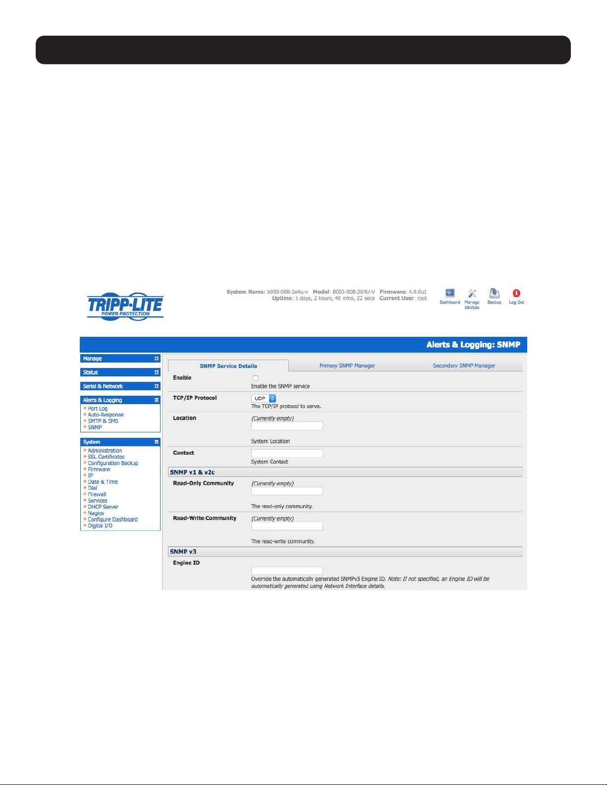
245
15. Advanced Configuration
15.5.2 Check Firewall Rules
Select System: Services. Ensure the SNMP daemon box has been checked for the interface required. This will allow SNMP
requests through the firewall for the specified interface.
15.5.3 Enable SNMP Service
The console server supports different versions of SNMP, including SNMPv1, SNMPv2c and SNMPv3.
SNMP, although an industry standard, brings with it a variety of security concerns. For example, SNMPv1 and SNMPv2c offer
no inherent privacy, while SNMPv3 is susceptible to man-in-the-middle attacks. Recent IETF developments suggests tunnelling
SNMP over widely accepted technologies such as SSH (Secure Shell) or TLS (Transport Layer Security), rather than relying on
a less mature security systems such as SNMPv3’s USM (User-based Security Model).
Additional information regarding SNMP security issues and SNMPv3 can be found at:
http://net-snmp.sourceforge.net/wiki/index.php/TUT:Security
http://www.ietf.org/html.charters/snmpv3-charter.html.
• Select Alerts & Logging: SNMP.
• The SNMP Service Details tab is shown by default. The SNMP Service Details tab controls aspects of the SNMP Service,
including Security Level. It manages requests from external agents for Tripp Lite status information.
• Check the Enable the SNMP Service box to start the SNMP Service. The service is disabled by default.
• Select either UDP or TCP for the TCP/IP Protocol. UDP is the recommended protocol and selected by default. TCP should
only be used in special cases, such as when Port Forwarding SNMP requests/responses to or from the Tripp Lite device is
required.
• Complete the Location and Contact fields. The Location field should describe the physical location of the Tripp Lite device
and will be used in response to requests for the SNMPv2-MIB::sysLocation.0 of the device. The Contact field refers to the
person responsible for the Tripp Lite device (i.e. System Administrator). This will be used in response to request SNMPv2-
MIB::sysContact.0.
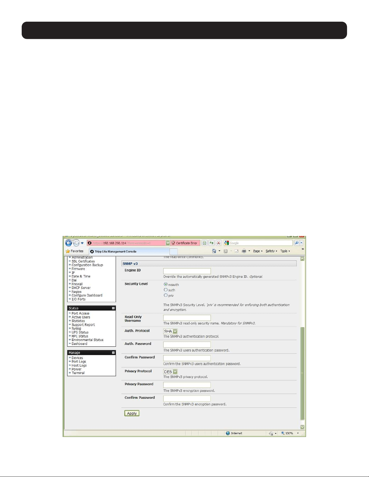
246
15. Advanced Configuration
• Enter the Read-Only Community and Read-Write Community. This is required for SNMP v1 & v2c only. The Read-
Only Community field is used to specify the SNMPv1 or SNMPv2c community allowed read-only (GET and GETNEXT) access.
This must be specified in order for both versions to become enabled. The Read-Write Community field is used to specify the
SNMPv1 or SNMPv2c community allowed read-write (GET, GETNEXT and SET) access.
• Configure SNMP v3, if required. SNMP v3 provides secure SNMP operations with USM (User-based Security Model). It
offers various levels of security, including user-based authentication and basic encryption.
o The Engine ID is used to localize the SNMPv3 user. It will automatically generate from a network interface (eth0) hardware
address if left blank, or must be entered as a hex value (e.g., 0x01020304).
o Specify the Security Level:
noauth No authentication or encryption is required. This is the minimum level of security.
auth Authentication is required but encryption is not enforced. An authentication protocol (SHA or MD5) and
password are required.
priv Enforces the use of encryption. This is the highest level of security and requires an encryption protocol (DES or
AES) and password, in addition to the authentication protocol and password.
o Complete the Read Only Username. Enter the read-only security name. This field is mandatory and must be completed
when configuring the console server for SNMPv3.
o For a Security Level of auth, select the Auth. Protocol (SHA or MD5) and the Auth. Password. A password of at least
8 characters is required.
o For a Security Level of priv, select the Privacy Protocol (DES or AES) and the Privacy Password. AES is
recommended, as it provides stronger privacy but requires more intense calculations. A password of at least 8 characters
is required.
• Click Apply.
• Set up serial ports and devices per operational requirements, such as UPS, RPC/PDU and EMD.

247
15. Advanced Configuration
• Copy the MIBs from /etc/snmp/mibs on the Tripp Lite product to a local directory using scp or Winscp. For example:
scp root@b098:/etc/snmp/mibs/*
• Using the snmpwalk and snmpget commands, the status information can be retrieved from any console server. For
example:
snmpwalk -Oa -v1 -M .:/usr/share/snmp/mibs -c public b098 TL-STATUS-MIB::tlStatus
snmpget -Oa -v1 -M .:/usr/share/snmp/mibs -c public b098 TL-STATUSMIB::
tlSerialPortStatusSpeed.2
noauth
snmpwalk -Oa –v3 –l noAuthNoPriv –u readonlyusername -M .:/usr/share/snmp/mibs b098 TL-STATUS-MIB::tlStatus
auth
snmpwalk -Oa –v3 –l authNoPriv –u readonlyusername –a SHA –A “authpassword” -M .:/usr/share/snmp/mibs b098 TL-STATUS-
MIB::tlStatus
priv
snmpwalk -Oa –v3 –l authNoPriv –u readonlyusername –a SHA –A “authpassword” –x DES –X “privpassword” -M .:/usr/share/snmp/mibs
b098 TL-STATUS-MIB::tlStatus
-l Security Level
-u Security Name or Read Only Username
-a Authentication Protocol – SHA or MD5
-A Authentication Password
-x Privacy Protocol – DES or AES
-X Privacy Password
A MIB browser may be used to explore the Tripp Lite enterprise MIB structure.
15.5.4 Adding Multiple Remote SNMP Managers
You can add multiple SNMP servers for alert traps and the first and second SNMP servers using the management console
(refer to 7. Alerts, Auto-Response and Logging) or the command line config tool. Further SNMP servers must be added
manually using config.
Log in to the console server’s command line shell as root or an admin user. Refer to the management console UI or user
documentation for descriptions of each field.
To set the SNMP Manager Address field:
config –set=”config.system.snmp.address3=w.x.y.z”
.. replacing w.x.y.z with the IP address or DNS name.
To set the Manager Trap Port field:
config --set=”config.system.snmp.trapport3=162”
.. replacing 162 with the TCP/UDP port number.
To set the SNMP Manager Protocol field:
config --set=”config.system.snmp.protocol3=UDP” or
config --set=”config.system.snmp.protocol3=TCP”
To set the SNMP Manager Version field:
config --set=”config.system.snmp.version3=3”
To set the SNMP Manager v1 & v2c community field:
config --set=”config.system.snmp.community3=public”
To set the SNMP Manager v3 Engine ID field:
config –set=”config.system.snmp.engineid3=0x8000000001020304”
.. replacing 0x8000000001020304 with the hex Engine-ID

248
15. Advanced Configuration
To set the SNMP Manager v3 Security Level field:
config --set=”config.system.snmp.seclevel3=noAuthNoPriv” or
config --set=”config.system.snmp.seclevel3=authNoPriv” or
config --set=”config.system.snmp.seclevel3=authPriv”
To set the SNMP Manager v3 Username field:
config --set=”config.system.snmp.username3=username”
To set the SNMP Manager v3 Auth. Protocol and password fields:
config –set=”config.system.snmp.authprotocol3=SHA” or
config --set=”config.system.snmp.authprotocol3=MD5”
config --set=”config.system.snmp.authpassword3=password 1”
To set the SNMP Manager v3 Privacy Protocol and password fields:
config –set=”config.system.snmp.privprotocol3=AES” or
config –set=”config.system.snmp.privprotocol3=DES”
config --set=”config.system.snmp.privpassword3=password 2”
Once the fields are set, apply the configuration with the following command:
config --run snmp
You can add a third or more SNMP servers by incrementing the “2” in the above commands (e.g., config.system.snmp.
protocol3, config.system.snmp.address3, etc.).
15.6 Secure Shell (SSH) Public Key Authentication
This section covers the generation of public and private keys in a Linux and Windows environment and configuring SSH for
public key authentication. The steps to use in a clustering environment are:
• Generate a new public and private key pair.
• Upload the keys to the primary device and to each secondary console server.
• Fingerprint each connection to validate.
15.6.1 SSH Overview
Popular TCP/IP applications such as telnet, rlogin, ftp and others transmit their passwords unencrypted. Doing this across
pubic networks like the Internet can have catastrophic consequences, as it allows an opening for eavesdropping, connection
hijacking, and other network-level attacks.
Secure Shell (SSH) is a program used to log into another computer over a network, execute commands in a remote machine
and move files from one machine to another. It provides strong authentication and secure communications over insecure
channels.
OpenSSH, the de facto open source SSH application, encrypts all traffic (including passwords) to effectively eliminate these
risks. Additionally, OpenSSH provides myriad secure tunneling capabilities, as well as a variety of authentication methods.
OpenSSH is the port of OpenBSD’s excellent OpenSSH[0] to Linux and other versions of UNIX. OpenSSH is based on the last
free version of Tatu Ylonen’s sample implementation, with all patent-encumbered algorithms removed (to external libraries),
all known security bugs fixed, new features reintroduced and many other fixes. The only changes in the Tripp Lite SSH
implementation are:
• PAM support.
• EGD[1]/PRNGD[2] support and replacements for OpenBSD library functions that are absent from other versions of UNIX.
• The config files are now in /etc/config. e.g.
o /etc/config/sshd_config instead of /etc/sshd_config
o /etc/config/ssh_config instead of /etc/ssh_config
o /etc/config/users/<username>/.ssh / instead of /home/<username>/.ssh/

249
15. Advanced Configuration
15.6.2 Generating Public Keys (Linux)
To generate new SSH key pairs, use the Linux ssh-keygen command. This will produce an RSA or DSA public/private key pair.
You will be prompted for a path to store the two key files e.g. id_dsa.pub (the public key) and id_dsa (the private key). For
example:
$ ssh-keygen -t [rsa|dsa]
Generating public/private [rsa|dsa] key pair.
Enter file in which to save the key (/home/user/.ssh/id_[rsa|dsa]):
Enter passphrase (empty for no passphrase):
Enter same passphrase again:
Your identification has been saved in /home/user/.ssh/id_[rsa|dsa].
Your public key has been saved in /home/user/.ssh/id_[rsa|dsa].pub.
The key fingerprint is:
28:aa:29:38:ba:40:f4:11:5e:3f:d4:fa:e5:36:14:d6 user@server
$
It is advisable to create a new directory to store your generated keys. It is also possible to name the files after the device for
which they will be used. For example:
$ mkdir keys
$ ssh-keygen -t rsa
Generating public/private rsa key pair.
Enter file in which to save the key (/home/user/.ssh/id_rsa): /home/user/keys/control_room
Enter passphrase (empty for no passphrase):
Enter same passphrase again:
Your identification has been saved in /home/user/keys/control_room
Your public key has been saved in /home/user/keys/control_room.pub.
The key fingerprint is:
28:aa:29:38:ba:40:f4:11:5e:3f:d4:fa:e5:36:14:d6 user@server
$
You must ensure no password is associated with the keys. If there is a password, the Tripp Lite devices will have no way to
supply it as runtime.
Full documentation for the ssh-keygen command can be found at http://www.openbsd.org/cgi-bin/man.cgi?query=ssh-
keygen .
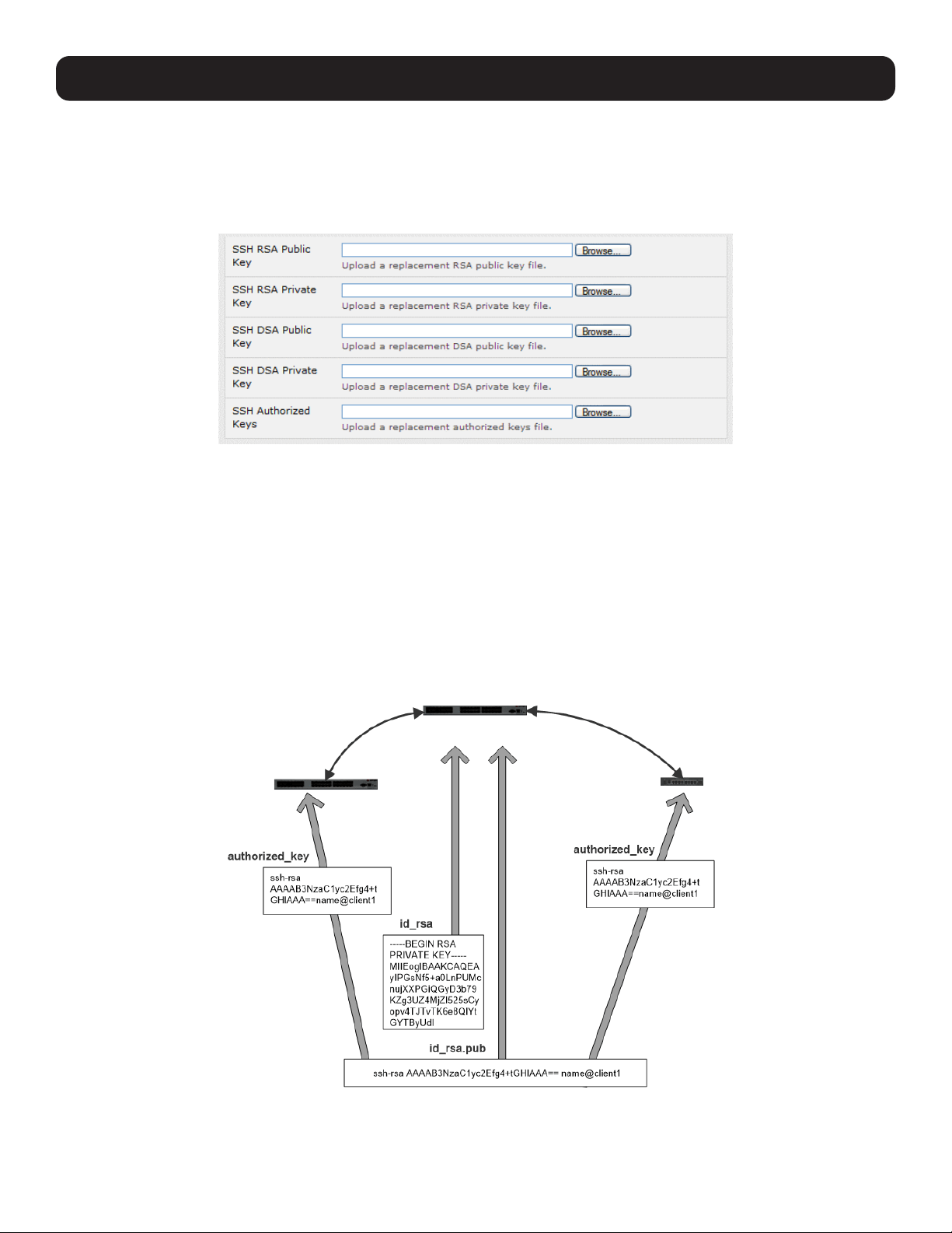
250
15. Advanced Configuration
15.6.3 Installing the SSH Public/Private Keys (Clustering)
For Tripp Lite console servers, the keys are simply uploaded through the web interface on the System: Administration
page. This enables you to upload stored RSA or DSA Public Key pairs to the Primary device and apply the authorized key to
the secondary device as described in 4. Serial Port, Host, Device and User Configuration. Once complete, proceed to
Fingerprinting, as described below.
15.6.4 Installing SSH Public Key Authentication (Linux)
Alternately, the public key can be installed on the unit remotely from the Linux host with the scp utility as follows:
Assuming the user on the management console is called “fred”; the console server IP address is 192.168.0.1 (default). The
public key is on the linux/unix computer in ~/.ssh/id_dsa.pub. Execute the following command on the linux/unix computer:
scp ~/.ssh/id_dsa.pub \
[email protected]:/etc/config/users/fred/.ssh/authorized_keys
The authorized_keys file on the console server needs to be owned by “fred”. As such, log in to the management console as
root and type:
chown fred /etc/config/users/fred/.ssh/authorized_keys
Secondary Secondary
Primary
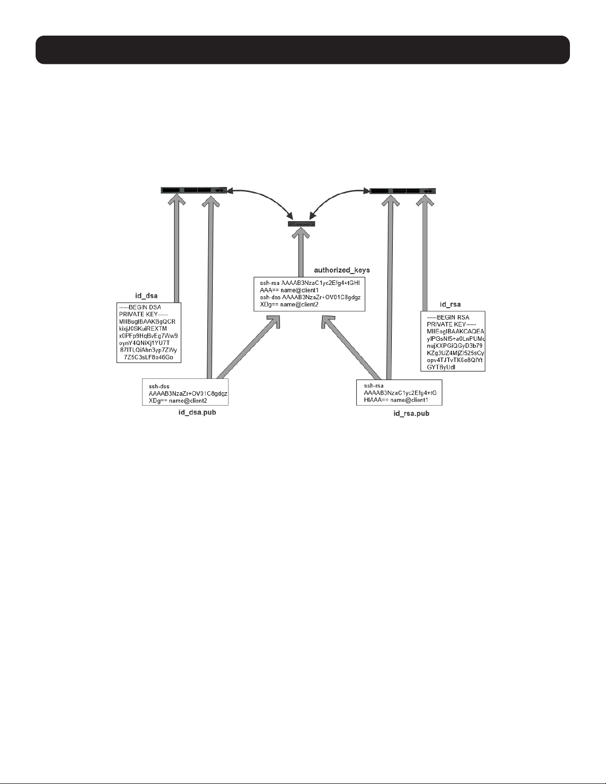
251
15. Advanced Configuration
If the Tripp Lite device selected to be the server will have only one client device, the authorized_keys file is simply a copy of
the public key for that device. If one or more devices will be clients of the server, the authorized_keys file will contain a copy
of all public keys. RSA and DSA keys may be freely mixed in the authorized_keys file. For example, assume we already have
one server, called bridge_server, and two sets of keys for the control_room and the plant_entrance:
$ ls /home/user/keys control_room control_room.pub plant_entrance plant_entrance.pub $ cat
/home/user/keys/control_room.pub /home/user/keys/plant_entrance.pub >
/home/user/keys/authorized_keys_bridge_server
More documentation on OpenSSH can be found at:
http://openssh.org/portable.html
http://www.openbsd.org/cgi-bin/man.cgi?query=ssh&sektion=1
http://www openbsd.org/cgi-bin/man.cgi?query=sshd.
15.6.5 Generating Public/Private Keys for SSH (Windows)
This section describes how to generate and configure SSH keys using Windows.
First, create a new user from the Tripp Lite management (the following example uses a user called “testuser”), making sure it
is a member of the “users” group.
If you do not already have a public/private key pair, you can generate them now using ssh-keygen, PuTTYgen or a similar tool:
PuTTYgen: http://www.chiark.greenend.org.uk/~sgtatham/putty/download.html
OpenSSH: http://www.openssh.org/
OpenSSH (Windows): http://sshwindows.sourceforge.net/download/
For example, when using PuTTYgen, make sure you have a recent version of the puttygen.exe (available from http://www.
chiark.greenend.org.uk/~sgtatham/putty/download.html). Also, make sure you have a recent version of WinSCP (available
from http://winscp.net/eng/download.php ).
To generate a SSH key using PuTTY http://sourceforge.net/docs/F02/#clients:
• Execute the PUTTYGEN.EXE program.
• Select the desired key type SSH2 DSA (you may use RSA or DSA) within the Parameters section.
• It is important that you leave the passphrase field blank.
• Click on the Generate button.
Secondary
Primary Primary
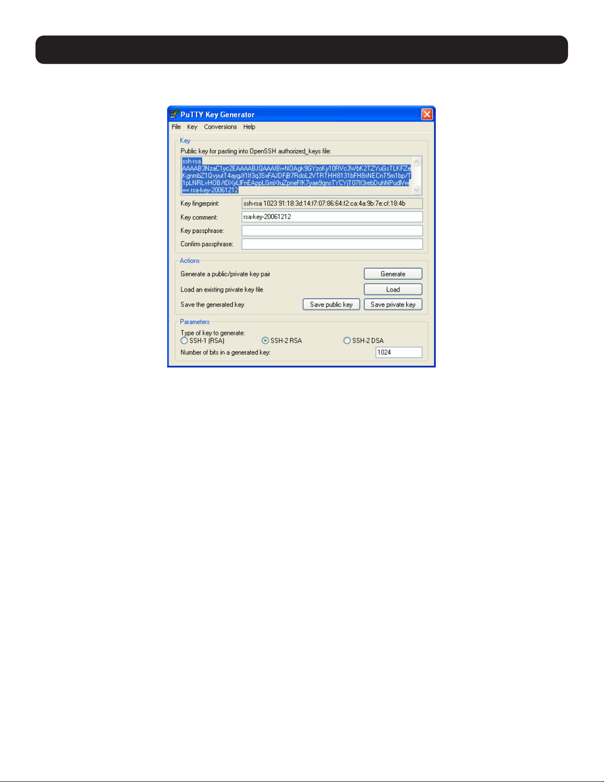
252
15. Advanced Configuration
• Follow the instruction to move the mouse over the blank area of the program in order to create random data used by
PUTTYGEN to generate secure keys. Key generation will occur once PUTTYGEN has collected sufficient random data.
• Create a new file “ authorized_keys “ (with notepad) and copy your public key data from the “Public key for pasting into
OpenSSH authorized_keys file” section of the PuTTY Key Generator. Paste the key data to the “authorized_keys” file. Make
sure there is only one line of text in this file.
• Use WinSCP to copy this “authorized_keys” file into the user’s home directory. For example, /etc/config/users/testuser/.
ssh/authorized_keys of the Tripp Lite gateway will be the SSH server. You will need to make sure this file is in the correct
format with the correct permissions with the following commands:
# dos2unix \
/etc/config/users/testuser/.ssh/authorized_keys && chown testuser \
/etc/config/users/testuser/.ssh/authorized_keys
• Using WinSCP, copy the attached sshd_config over /etc/config/sshd_config on the server. Doing this ensures public key
authentication is enabled.
• Test the Public Key by logging in as “testuser”. Test the Public Key by logging in as “testuser” to the client Tripp Lite device
and typing (you should not need to enter anything):
# ssh -o StrictHostKeyChecking=no <server-ip>
To automate connection of the SSH tunnel from the client on every power-up, make the clients /etc/config/rc.local look like the
following:
#!/bin/sh
ssh -L9001:127.0.0.1:4001 -N -o StrictHostKeyChecking=no testuser@<server-ip> &
This will run the tunnel redirecting local port 9001 to the server port 4001.
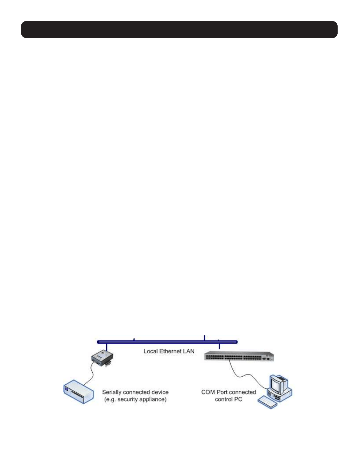
253
15. Advanced Configuration
15.6.6 Fingerprinting
Fingerprints are used to ensure you are establishing an SSH session to who you think you are. On the first connection to a
remote server, you will receive a fingerprint that can be used for future connections.
This fingerprint is related to the host key of the remote server. Fingerprints are stored in ~/.ssh/known_hosts.
To receive the fingerprint from the remote server, log in to the client as the required user (usually root) and establish a
connection to the remote host:
# ssh remhost
The authenticity of host ‘remhost (192.168.0.1)’ can’t be established.
RSA key fingerprint is 8d:11:e0:7e:8a:6f:ad:f1:94:0f:93:fc:7c:e6:ef:56.
Are you sure you want to continue connecting (yes/no)?
Answer yes to accept the key. The following message will appear:
Warning: Permanently added ‘remhost,192.168.0.1’ (RSA) to the list of
known hosts.
You may be prompted for a password, though there is no need to log in; you will have received the fingerprint and can Ctrl+C
to cancel the connection. If the host key changes, you will receive the following warning and not be allowed to connect to the
remote host:
@@@@@@@@@@@@@@@@@@@@@@@@@@@@@@@@
@ WARNING: REMOTE HOST IDENTIFICATION HAS CHANGED! @
@ IT IS POSSIBLE THAT SOMEONE IS DOING SOMETHING NASTY! @
@@@@@@@@@@@@@@@@@@@@@@@@@@@@@@@@
Someone could be eavesdropping on you right now (man-in-the-middle attack)!
It is also possible that the RSA host key has just been changed.
The fingerprint for the RSA key sent by the remote host is:
ab:7e:33:bd:85:50:5a:43:0b:e0:bd:43:3f:1c:a5:f8.
Please contact your system administrator.
Add correct host key in /.ssh/known_hosts to get rid of this message.
Offending key in /.ssh/known_hosts:1
RSA host key for remhost has changed and you have requested strict checking.
Host key verification failed.
If the host key has been legitimately changed, it can be removed from the ~/.ssh/known_hosts file with the new fingerprint
added. If it has not changed, this indicates a serious problem that should be investigated immediately.
15.6.7 SSH Tunneled Serial Bridging
You have the option to apply SSH tunneling when two Tripp Lite console servers are configured for serial bridging.
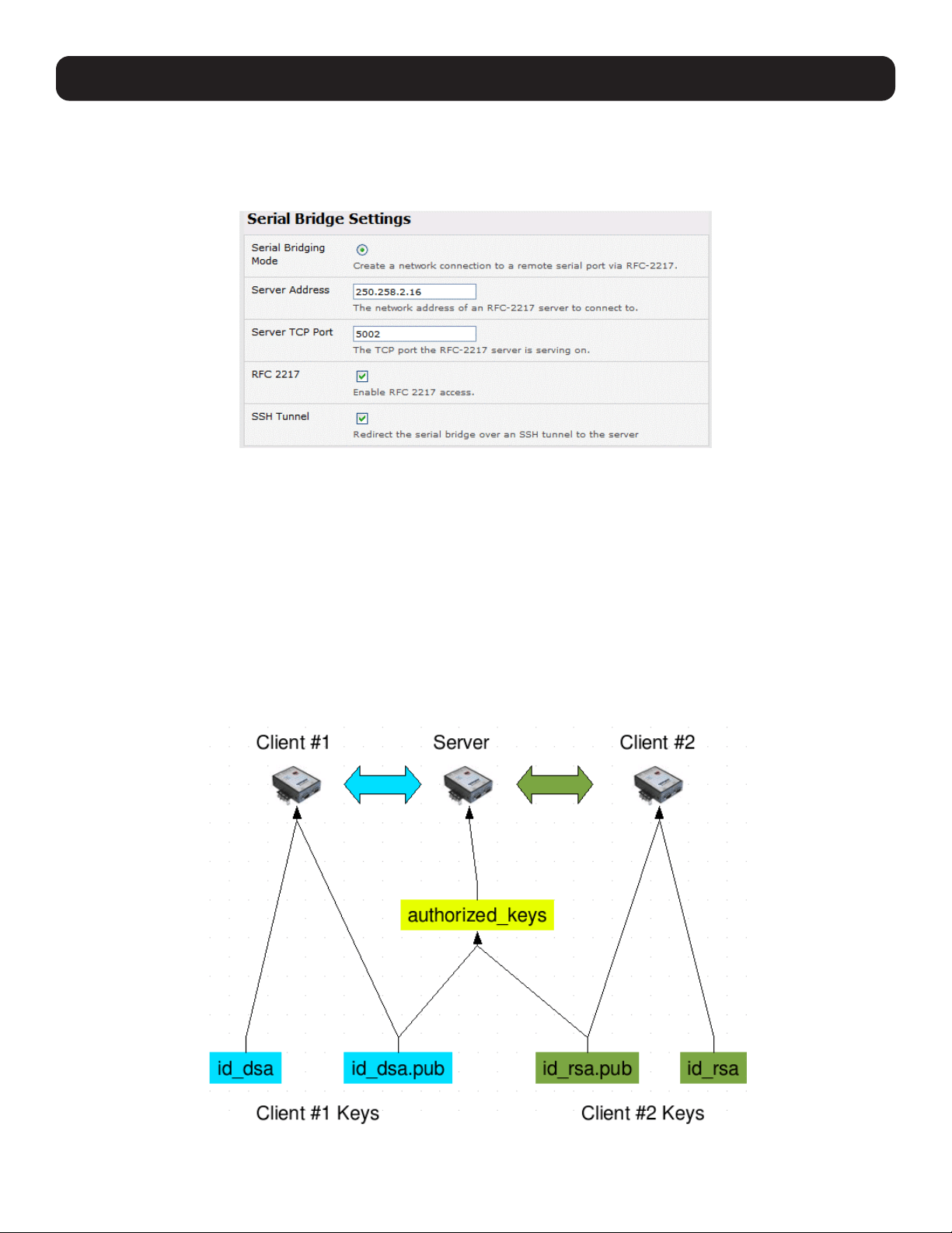
254
15. Advanced Configuration
As detailed in 4. Serial Port, Host, Device and User Configuration, the server console server is set up in Console Server
mode with either RAW or RFC2217 enabled, and the client console server is set up in Serial Bridging mode with the Server
Address and Server TCP Port (4000 + port for RAW or 5000 + port # for RFC2217) specified:
• Select SSH Tunnel when configuring the Serial Bridging Setting.
Next, you will need to set up SSH keys for each end of the tunnel and upload these keys to the server and client console
servers.
Client Keys
The first step in setting up SSH tunnels is to generate keys. Ideally, you will use a separate, secure machine to generate and
store all keys to be used on the console servers. However, if this is not ideal to your situation, keys may be generated on the
console servers themselves.
It is possible to generate only one set of keys and reuse them for every SSH session. While this is not recommended, each
organization will need to balance the security of separate keys against the additional administration they bring.
Generated keys may be one of two types - RSA or DSA (and it is beyond the scope of this document to recommend one over
the other). RSA keys will go into the files id_rsa and id_rsa.pub. DSA keys will be stored in the files id_dsa and id_dsa.pub.
For simplicity, the term private key will be used from this point forward to refer to either id_rsa or id_dsa and public key to
refer to either id_rsa.pub or id_dsa.pub.

255
15. Advanced Configuration
To generate the keys using OpenBSD’s OpenSSH suite, use the ssh-keygen program:
$ ssh-keygen -t [rsa|dsa]
Generating public/private [rsa|dsa] key pair.
Enter file in which to save the key (/home/user/.ssh/id_[rsa|dsa]):
Enter passphrase (empty for no passphrase):
Enter same passphrase again:
Your identification has been saved in /home/user/.ssh/id_[rsa|dsa].
Your public key has been saved in /home/user/.ssh/id_[rsa|dsa].pub.
The key fingerprint is:
28:aa:29:38:ba:40:f4:11:5e:3f:d4:fa:e5:36:14:d6 user@server
$
It is advisable to create a new directory to store your generated keys. It is also possible to name the files after the device they
will be used for. For example:
$ mkdir keys
$ ssh-keygen -t rsa
Generating public/private rsa key pair.
Enter file in which to save the key (/home/user/.ssh/id_rsa): /home/user/keys/control_room
Enter passphrase (empty for no passphrase):
Enter same passphrase again:
Your identification has been saved in /home/user/keys/control_room
Your public key has been saved in /home/user/keys/control_room.pub.
The key fingerprint is:
28:aa:29:38:ba:40:f4:11:5e:3f:d4:fa:e5:36:14:d6 user@server
$
You should ensure there is no password associated with the keys. If there is a password, the console servers will have no way
to supply it as runtime.
Authorized Keys
If the console server selected to be the server will have only one client device, then the authorized_keys file is simply a copy
of the public key for that device. If one or more devices will be clients of the server, the authorized_keys file will contain a
copy of all of the public keys. RSA and DSA keys may be freely mixed in the authorized_keys file.
For example, assume we already have one server, called bridge_server, and two sets of keys for the control_room and the
plant_entrance:
$ ls /home/user/keys
control_room control_room.pub plant_entrance plant_entrance.pub
$ cat /home/user/keys/control_room.pub
/home/user/keys/plant_entrance.pub >
/home/user/keys/authorized_keys_bridge_server
Uploading Keys
The server keys can be uploaded through the web interface on the System: Administration page. If only one client will be
connecting, simply upload the appropriate public key as the authorized keys file. Otherwise, upload the authorized keys file
constructed in the previous step.
Each client will then need its own set of keys uploaded through the same page. Take care to ensure the correct type of keys
(DSA or RSA) goes in the correct locations and that the public and private keys are in the correct location.

256
15. Advanced Configuration
15.6.8 SDT Connector Public Key Authentication
SDT Connector can authenticate against a console server using your SSH key pair, rather than requiring you to enter your
password (i.e. public key authentication).
• To use public key authentication with SDT Connector, first create an RSA or DSA key pair (using ssh-keygen, PuTTYgen or a
similar tool) and add the public part of your SSH key pair to the console server.
• Next, add the private part of your SSH key pair (this file is typically named id_rsa or id_dsa) to SDT Connector client. Click
Edit: Preferences: Private Keys: Add, locate the private key file and click OK. You do not have to add the public part of
your SSH key pair, it is calculated using the private key.
SDT Connector will now use public key authentication when SSH connects via console server. You may have to restart SDT
Connector to shut down any existing tunnels that were established using password authentication.
If you have a host behind the console server that you connect to by clicking the SSH button in SDT Connector, you can also
configure it for public key authentication. Essentially, what you are using is SSH over SSH. The two SSH connections are
entirely separate, and the host configuration is entirely independent of SDT Connector and the console server. You must
configure the SSH client that SDT Connector launches (e.g., Putty, OpenSSH) and the host’s SSH server for public key
authentication.
15.7 Secure Sockets Layer (SSL) Support
Secure Sockets Layer (SSL) is a protocol developed by Netscape for transmitting private documents via the Internet. SSL
works by using a private key to encrypt data transferred over the SSL connection.
The console server includes OpenSSL. The OpenSSL Project is a collaborative effort to develop a robust, commercial-grade,
full-featured and open source toolkit implementing the Secure Sockets Layer (SSL v2/v3) and Transport Layer Security (TLS v1)
protocols, as well as a full-strength general-purpose cryptography library. The project is managed by a worldwide community of
volunteers that use the Internet to communicate, plan and develop the OpenSSL toolkit and its related documentation.
OpenSSL is based on the Slay library developed by Eric A. Young and Tim J. Hudson. The OpenSSL toolkit is licensed under
an Apache-style license, which means you are free to get and use it for commercial and non-commercial purposes subject
to some simple license conditions. In the console server, OpenSSL is used primarily in conjunction with http in order to have
secure browser access to the GUI management console across insecure networks.
More documentation on OpenSSL is available at:
http://www.openssl.org/docs/apps/openssl.html
http://www.openssl.org/docs/HOWTO/certificates.txt
15.8 HTTPS
The management console UI is served using HTTPS by the built in Cherokee webserver.
If your default network address is changed or the unit is to be accessed using a known domain name, you can use the
following steps to replace the default SSL certificate and private key with those tailored for your new address.
15.8.1 Generating an Encryption Key
To create a 1024-bit RSA key with a password, issue the following command on the Linux host command line with the openssl
utility installed:
openssl genrsa -des3 -out ssl_key.pem 1024

257
15. Advanced Configuration
15.8.2 Generating a Self-Signed Certificate with OpenSSL
This example shows how to use OpenSSL to create a self-signed certificate. OpenSSL is available for most Linux distributions
using the default package management mechanism. Windows users can check by going to http://www.openssl.org/related/
binaries.html.
To create a 1024-bit RSA key and a self-signed certificate, issue the following openssl command from the host you have
openssl installed on:
openssl req -x509 -nodes -days 1000 \
-newkey rsa:1024 -keyout ssl_key.pem -out ssl_cert.pem
You will be prompted to enter a lot of information. Most does not matter, but the “Common Name” should be the domain
name of your computer (e.g., test.tripplite.com). Once everything has been entered, the certificate will be created in a file
called ssl_cert.pem.
15.8.3 Installing the Key and Certificate
The recommended method for copying files securely to the console server is with an SCP (Secure Copying Protocol) client.
The scp utility is distributed with OpenSSH for most UNIX distributions, while Windows users can use something like the PSCP
command line utility available with PuTTY.
The files created in the steps above can be installed remotely with the scp utility as follows:
scp ssl_key.pem root@<address of unit>:/etc/config/
scp ssl_cert.pem root@<address of unit>:/etc/config/
or using PSCP:
pscp -scp ssl_key.pem root@<address of unit>:/etc/config/
pscp -scp ssl_cert.pem root@<address of unit>:/etc/config/
PuTTY and the PSCP utility can be downloaded from: http://www.chiark.greenend.org.uk/~sgtatham/putty/download.html.
More detailed documentation on the PSCP can be found at: http://the.earth.li/~sgtatham/putty/0.58/htmldoc/Chapter5.
html#pscp.
15.8.4 Launching the HTTPS Server
The easiest way to enable the HTTPS server is from the web management console. Simply click the appropriate checkbox in
Network: Services: HTTPS Server. The HTTPS server will be activated, assuming the ssl_key.pem & ssl_cert.pem files exist
in the /etc/config directory.
Alternately, inetd can be configured to launch the secure fnord server from the command line of the unit as follows.
Edit the inetd configuration file. From the unit command line:
vi /etc/config/inetd.conf
Append a line:
443 stream tcp nowait root sslwrap -cert /etc/config/ssl_cert.pem -key /etc/config/ssl_key.pem -exec /bin/httpd /home/httpd”
Save the file and signal inetd of the configuration change.
kill -HUP `cat /var/run/inetd.pid`
The HTTPS server should be accessible from a web client at a URL similar to: https://<common name of unit>
More detailed documentation about the openssl utility can be found at: http://www.openssl.org/

258
15. Advanced Configuration
15.9 Power Strip Control
The console server supports a growing list of remote power-control devices (RPCs), which can be configured using the
management console as described in 8. Power, Environment and Digital I/O. These RPCs are controlled using the open source
PowerMan and Network UPS Tools, and with Tripp Lite’s pmpower utility.
15.9.1 PowerMan Tool
PowerMan provides power management in a data center or compute cluster environment. It performs operations such as
power on, power off and power cycle via remote power controller (RPC) devices.
Synopsis
powerman [-option] [targets]
pm [-option] [targets]
Options
-1, --on Power ON targets.
-0, --off Power OFF targets.
-c, --cycle Power cycle targets.
-r, --reset Assert hardware reset for targets (if implemented by RPC).
-f, --flash Turn beacon ON for targets (if implemented by RPC).
-u, --unflash Turn beacon OFF for targets (if implemented by RPC).
-l, --list List available targets. If possible, output will be compressed into a host range (see TARGET
SPECIFICATION below).
-q, --query Query plug status of targets. If none specified, query all targets. Status is not cached; each
time this option is used, PowerMan queries the appropriate RPCs. Targets connected to RPCs
that could not be contacted (e.g., due to network failure) are reported as status “unknown”. If
possible, output will be compressed into host ranges.
-n, --node Query node power status of targets (if implemented by RPC). If no targets are specified, query
all targets. In this context, a node in the OFF state could be ON at the plug, but operating in
standby power mode.
-b, --beacon Query beacon status (if implemented by RPC). If no targets are specified, query all targets.
-t, --temp Query node temperature (if implemented by RPC). If no targets are specified, query all targets.
Temperature information is not interpreted by PowerMan and is reported as received from the
RPC on one line per target, prefixed by target name.
-h, --help Display option summary.
-L, --license Show PowerMan license information.
-d, --destination host[:port] Connect to a PowerMan daemon on non-default host and optional port.
-V, --version Display the PowerMan version number and exit.
-D, --device Displays RPC status information. If targets are specified, only RPCs matching the target list are
displayed.
-T, --telemetry Causes RPC telemetry information to be displayed as commands are processed. Useful for
debugging device scripts.
-x, --exprange Expand host ranges in query responses.
For more details, refer to http://linux.die.net/man/1/powerman.
Also, refer to powermand (http://linux.die.net/man/1/powermand) documentation and powerman.conf (http://linux.die.
net/man/5/powerman.conf).

259
15. Advanced Configuration
Target Specification
PowerMan target hostnames may be specified as comma-separated or space-separated hostnames or host ranges. Host
ranges are of the general form: prefix[n-m,l-k,...], where n < m and l < k, etc. This form should not be confused with regular
expression character classes (also denoted by ‘’[]’’). For example, foo[19] does not represent foo1 or foo9, but rather
represents a degenerate range: foo19.
This range syntax is meant only as a convenience on clusters with a prefix NN naming convention. Range specification should
not be considered necessary; the list foo1,foo9 could be specified as such, or by the range foo[1,9].
Some examples of PowerMan targets include:
Power on hosts bar,baz,foo01,foo02,...,foo05: powerman --on bar baz foo[01-05]
Power on hosts bar,foo7,foo9,foo10: powerman --on bar,foo[7,9-10]
Power on foo0,foo4,foo5: powerman --on foo[0,4-5]
As a reminder, some shells will interpret brackets ([ and ]) for pattern matching. Depending on your shell, it may be necessary
to enclose ranged lists within quotes. For example, in tcsh, the last example above should be executed as:
powerman --on “foo[0,4-5]”
15.9.2 Pmpower tool
The pmpower utility is a high-level tool for manipulating remote preconfigured power devices connected to the console
server via serial or network connection. The PDU, UPS and IPMI power devices are variously controlled using the open
source PowerMan, IPMItool or Network UPS Tools. Tripp Lite’s pmpower utility arches over these tools so devices can be
controlled through the one command line:
pmpower [-?h] [-l device | -r host] [-o outlet] [-u username] [-p password] action
-?/-h This help message.
-l The serial port to use.
-o The outlet on the power target to apply to.
-r The remote host address for the power target.
-u Override the configured username.
-p Override the configured password.
on This action switches the specified device or outlet(s) on.
off This action switches the specified device or outlet(s) off.
cycle This action switches the specified device or outlet(s) off and on again.
status This action retrieves the current status of the device or outlet.
Examples:
To turn outlet 4 of the power device connected to serial port 2 on: # pmpower -l port02 -o 4 on
To turn an IPMI device off located at IP address 192.168.1.100 (where username is ‘root’ and password is ‘calvin’: #
pmpower -r 192.168.1.100 -u root -p calvin off
Default system power device actions are specified in /etc/powerstrips.xml. Custom power devices can be added in /etc/
config/powerstrips.xml. If an action is attempted which has not been configured for a specific power device, pmpower will
exit with an error.

260
15. Advanced Configuration
15.9.3 Adding New RPC Devices
There are a number of simple paths to adding support for new RPC devices.
The first is to have scripts support the particular RPC included in either the open source PowerMan project (http://
sourceforge.net/projects/powerman) or the open source NUT UPS Tools project. The PowerMan device specifications
are rather peculiar, and it is suggested you leave the actual writing of these scripts to the PowerMan authors. However,
documentation on how they work can be found at http://linux.die.net/man/5/powerman.dev. The Network UPS Tools (NUT)
project has recently moved on from its UPS management origins to also cover SNMP PDUs (and embrace PowerMan). Tripp
Lite progressively includes the updated PowerMan and NUT build into the console server firmware releases.
The second path is to directly add support for the new RPC devices (or to customize the existing RPC device support) on
your console server. The Manage: Power page uses information contained in /etc/powerstrips.xml to configure and control
devices attached to a serial port. The configuration also searches for (and loads) /etc/config/powerstrips.xml (if it exists).
The user can add their own support for more devices by adding their definitions into /etc/config/powerstrips.xml. This file can
be created on a host system and copied to the management console device using scp. Alternately, log in to the management
console and use ftp or wget to transfer files.
Here is a brief description of the elements of the XML entries in /etc/config/powerstrips.xml:
<powerstrip>
<id>Name or ID of the device support</id>
<outlet port=”port-id-1”>Display Port 1 in menu</outlet>
<outlet port=”port-id-2”>Display Port 2 in menu</outlet>
...
<on>script to turn power on</on>
<off>script to power off</off>
<cycle>script to cycle power</cycle>
<status>script to write power status to /var/run/power-status</status>
<speed>baud rate</speed>
<charsize>character size</charsize>
<stop>stop bits</stop>
<parity>parity setting</parity>
</powerstrip>
The id appears on the web page in the list of available devices types to configure.
The outlets describe targets that the scripts can control. For example, a power control board may control several different
outlets. The port-id is the native name for identifying the outlet. This value will be passed to the scripts in the environment
variable outlet, allowing the script to address the correct outlet.
There are four possible scripts: on, off, cycle and status.
When a script is run, its standard input and output is redirected to the appropriate serial port. The script receives the outlet
and port in the outlet and port environment variables, respectively.
The script can be anything that can be executed within the shell.
All of the existing scripts in /etc/powerstrips.xml use the pmchat utility.
pmchat works just like the standard UNIX “chat” program, except it ensures interoperation with the port manager.
The final options speed, charsize, stop and parity define the recommended or default settings for the attached device.

261
15. Advanced Configuration
15.10 IPMItool
The console server includes the ipmitool utility for managing and configuring devices that support the Intelligent Platform
Management Interface (IPMI) versions 1.5 and 2.0 specifications.
IPMI is an open standard for monitoring, logging, recovery, inventory and control of implemented hardware independent of
the main CPU, BIOS and OS. The service processor (or Baseboard Management Controller, BMC) is the brain behind platform
management. Its primary purpose is to handle autonomous sensor monitoring and event logging.
The ipmitool program provides a simple command-line interface to the BMC. It features the ability to read the sensor data
repository (SDR) and print sensor values, display the contents of the System Event Log (SEL), print Field Replaceable Unit
(FRU) inventory information, read and set LAN configuration parameters, and perform remote chassis power control.
SYNOPSIS
ipmitool [-c|-h|-v|-V] -I open <command>
ipmitool [-c|-h|-v|-V] -I lan -H <hostname>
[-p <port>]
[-U <username>]
[-A <authtype>]
[-L <privlvl>]
[-a|-E|-P|-f <password>]
[-o <oemtype>]
<command>
ipmitool [-c|-h|-v|-V] -I lanplus -H <hostname>
[-p <port>]
[-U <username>]
[-L <privlvl>]
[-a|-E|-P|-f <password>]
[-o <oemtype>]
[-C <ciphersuite>]
<command>
Description
This program lets you manage Intelligent Platform Management Interface (IPMI) functions of either the local system via a
kernel device driver or a remote system using IPMI version 1.5 and 2.0. These functions include printing FRU information, LAN
configuration, sensor readings and remote chassis power control.
IPMI management of a local system interface requires a compatible IPMI kernel driver to be installed and configured. On
Linux systems, this driver is called OpenIPMI and is included in standard distributions. On Solaris systems, this driver is called
BMC and is included in Solaris 10. Management of a remote station requires the IPMI-over-LAN interface to be enabled and
configured. Depending on the particular requirements of each system, it may be possible to enable the LAN interface using
ipmitool over the system interface.
Options
-a Prompt for the remote server password.
-A <authtype> Specify an authentication type to use during IPMIv1.5 lan session activation. Supported types are
NONE, PASSWORD, MD5, or OEM.
-c Present output in CSV (comma separated variable) format. This is not available with all commands.
-C <ciphersuite> The remote server authentication, integrity, and encryption algorithms to use for IPMIv2 lanplus
connections. See table 22-19 in the IPMIv2 specification. The default is 3, which specifies RAKP-
HMAC-SHA1 authentication, HMAC-SHA1-96 integrity, and AES-CBC-128 encryption algorithms.
-E The remote server password is specified by the environment variable IPMI_PASSWORD.
-f <password_file> Specifies a file containing the remote server password. If this option is absent, or if password_file is
empty, the password will default to NULL.
-h Get basic usage help from the command line.

262
15. Advanced Configuration
-H <address> Remote server address. Can be IP address or hostname. This option is required for lan and
lanplus interfaces.
-I <interface> Selects IPMI interface to use. Supported interfaces that are compiled in are visible in the usage
help output.
-L <privlvl> Force session privilege level. Can be CALLBACK, USER, OPERATOR, and ADMIN. Default is ADMIN.
-m <local_address> Set the local IPMB address. The default is 0x20. There is no need to change this setting under
normal operation.
-o <oemtype> Select the OEM type to support. This usually involves minor hacks in place in the code to work
around quirks in various BMCs from various manufacturers. Use -o list to see a list of current
supported OEM types.
-p <port> Remote server UDP port to connect to. Default is 623.
-P <password> Remote server password is specified on the command line. If supported, it will be obscured in the
process list.
Note: Specifying the password as a command line option is not recommended.
-t <target_address> Bridge IPMI requests to the remote target address.
-U <username> Remote server username, default is NULL user.
-v Increase verbose output level. This option may be specified multiple times to increase the level of
debug output. If given three times, you will get hexdumps of all incoming and outgoing packets.
-V Display version information.
If no password method is specified, ipmitool will prompt the user for a password. If no password is entered at the prompt, the
remote server password will default to NULL.
Security
The ipmitool documentation highlights several security issues that should be considered before enabling the IPMI LAN
interface. A remote station has the ability to control a system’s power state as well as the ability to gather certain platform
information. To reduce vulnerability, it is strongly advised that the IPMI LAN interface only be enabled in trusted environments
where system security is not an issue, where there is a dedicated secure management network, or access has been provided
through a console server.
It is strongly advised you should not enable IPMI for remote access without setting a password and that the password should
not be the same as any other password on that system.
When an IPMI password is changed on a remote machine with the IPMIv1.5 lan interface, the new password is sent across
the network as clear text. This could be observed and then used to attack the remote system. As such, it is recommended that
IPMI password management only be performed over IPMIv2.0 lanplus interface or the system interface on the local station.
For IPMI v1.5, the maximum password length is 16 characters. Passwords longer than 16 characters will be truncated.
For IPMI v2.0, the maximum password length is 20 characters. Passwords longer than 20 characters will be truncated.
Commands
help This can be used to get command-line help on ipmitool commands. It may also be placed at the
end of commands to get option usage help.
ipmitool help Commands:
raw Send a RAW IPMI request and print response
lan Configure LAN Channels
chassis Get chassis status and set power state
event Send pre-defined events to MC
mc Management Controller status and global enables
sdr Print Sensor Data Repository entries and readings
sensor Print detailed sensor information

263
fru Print built-in FRU and scan SDR for FRU locators
sel Print System Event Log (SEL)
pef Configure Platform Event Filtering (PEF)
sol Configure IPMIv2.0 Serial-over-LAN
isol Configure IPMIv1.5 Serial-over-LAN
user Configure Management Controller users
channel Configure Management Controller channels
session Print session information
exec Run list of commands from file
set Set runtime variable for shell and exec
ipmitool chassis help Chassis Commands: status, power, identify, policy, restart_cause, poh, bootdev
ipmitool chassis power help chassis power Commands: status, on, off, cycle, reset, diag, soft
You will find more details on ipmitools at http://ipmitool.sourceforge.net/manpage.html.
15.11 Custom Development Kit (CDK)
Copy scripts, binaries and configuration files directly to the console server.
Tripp Lite also provides a free development kit that allows changes to be made to the software in console server firmware
image. The customer can use the CDK to:
• Generate a firmware image without certain programs such as telnet, which may be banned by company policy.
• Generate an image with new programs such as custom Nagios plug-in binaries or company specific binary utilities.
• Generate an image with custom defaults (e.g., it may be required that the console server be configured to have a specific
default serial port profile which is reverted to in the event of a factory reset.
• Place configuration files into the firmware image, which cannot then be modified. For example, # /bin/config –-set= tools
update the configuration files in /etc/config which are read/write, whereas the files in /etc are read only and cannot be
modified.
The CDK provides a snapshot of the Tripp Lite build process (taken after the programs have been compiled and copied to a
temporary directory romfs) just before the compressed file systems are generated.
When the console servers are cascaded, the Primary unit is in control of the serial ports on the Secondary units, and the
primary’s management console provides a consolidated view of the settings for both its own and all the secondary unit’s serial
ports. However, the Primary unit does not provide a fully consolidated view. For example, Status: Active Users only displays
those users active on the Primary unit’s ports; you will need to write a custom bash script that parses the port logs if you want
to find out who’s logged in to cascaded serial ports from the Primary.
You will also want to enable remote or USB logging. Local logs only buffer 8K of data and do not persist between reboots.
This script would parse each port log file line by line. For example, each time it sees ‘LOGIN: username’, it adds username to
the list of connected users for that port, and each time it sees ‘LOGOUT: username’ it removes it from the list. In doing this,
the list can be neatly formatted and displayed. It is also possible to run this as a CGI script on the remote log server.
To enable log storage and connection logging:
• Select Alerts & Logging: Port Log.
• Configure log storage.
• Select Serial & Network: Serial Port. Edit the serial port(s).
• Under Console server, select Logging Level 1 and click Apply.
A useful tutorial on creating a bash script CGI can be found at: http://www.yolinux.com/TUTORIALS/
LinuxTutorialCgiShellScript.html
15. Advanced Configuration

264
15. Advanced Configuration
Similarly, the Primary unit will maintain a view of the status of the secondary units:
• Select Status: Support Report.
• Scroll down to Processes.
• Look for: /bin/ssh -MN -o ControlPath=/var/run/cascade/%h Secondaryname
These are the Secondary units that are connected.
• The end of the Secondary units’ names will be truncated, so the first five characters must be unique.
Alternately, you can write a custom CGI script as described above. The connected Secondary units can be determined
by running: ls /var/run/cascade. The configured Secondarys can be displayed by running: config -g config.cascade.
Secondarys
15.12 SMS Server Tools
Firmware releases V3.1 and later include the SMS Server Tools software, which provides an SMS gateway that sends and
receives short messages through GSM modems and mobile phones.
You can send short messages by simply storing text files into a special spool directory. The program monitors this directory
and sends new files automatically. It also stores received short messages into another directory as text files. Binary messages
(including Unicode text) are also supported (e.g., ring tone messages). It is also possible to send a WAP Push message to the
WAP / MMS capable mobile phone.
The program can be run as an SMS daemon, which can be started automatically when the operating system starts. High
availability can be ensured by using multiple GSM devices (currently up to 64, though this limit is easily changeable).
The program can run other external programs or scripts after events like receiving a new message and successfully sending a
message. It can inform when the program detects a problem. These programs can inspect the related text files and perform
automatic actions
The SMS Server Tools software needs a GSM modem (or mobile phone) with SMS command set according to the European
specifications GSM 07.05 (=ETSI TS 300 585) and GSM 03.38 (=ETSI TS 100 900). AT command set is supported. Devices
can be connected with serial port, infrared or USB.
For more information, refer to http://smstools3.kekekasvi.com.
15.13 Multicast
By default, all Tripp Lite console servers come with multicasting enabled. Multicasting provides Tripp Lite products with the
ability to simultaneously transmit information from a single device to a select group of hosts.
Multicasting can be disabled and re-enabled from the command line when used with firmware release version 3.1 and later. To
disable multicasting type:
ifconfig eth0 -multicast
To re-enable multicasting from the command line type:
ifconfig eth0 multicast
IPv6 may need to be restarted when toggling between multicast states.

265
15. Advanced Configuration
15.14 Bulk Provisioning
Tripp Lite devices include wizard scripts to facilitate configuration and deployment en masse. These wizards operate at the
command line level, so knowledge of the Linux command line and shell scripting is useful, but not necessary. Rather, they aim
to be sufficiently user-friendly for remote hands to manage. This bulk-provisioning feature is supported by firmware version
3.9.1 or later.
The basic steps are:
1. Configure an individual “golden Primary” appliance with the baseline configuration shared by all Tripp Lite devices. This
may be a minimal configuration if the installs are quite diverse, or a complete configuration when dealing with replicated
installs.
2. Use make-template to turn the golden Primary’s active configuration into a template configuration that may be applied to
other devices.
3. Create an OPG backup of the templated golden Primary appliance.
4. Restore this configuration to each target devices via the CLI, web UI or using a USB thumb drive.
5. Login via the CLI to complete configuration using setup-wizard.
15.15 Zero Touch Provisioning
Zero Touch Provisioning (ZTP) was introduced with firmware release 3.15.1 to allow Tripp Lite devices to be provisioned during
their initial boot from a DHCP server.
15.15.1 Preparation
These are typical steps for configuration over a trusted network:
1. Configure a same-model Tripp Lite device.
2. Optionally use the Bulk Provisioning wizard scripts to remove any appliance-specific settings (i.e. create a template
configuration). Refer to 15.14 Bulk Provisioning for more information.
3. Save the configuration as a Tripp Lite backup (.opg) file under System: Configuration Backup in the web UI, or via config
-e in the CLI. Alternately, you can save the XML configuration as a file ending in .xml.
4. Publish the .opg or.xml file on a fileserver that understands one of the HTTPS, HTTP, FTP or TFTP protocols.
5. Configure your DHCP server to include a “vendor specific” option for Tripp Lite devices. The option text should be a URL to
the location of the .opg or .xml file. The option text should not exceed 250 characters in length. It must end in either .opg
or .xml.
6. Connect a new Tripp Lite device (either at defaults from the factory, or config erased) to the network. Apply power.
7. It may take up to 5 minutes for the device to find the .opg or .xml file via DHCP, download, install file and reboot.
15.15.2 Example ISC DHCP Server Configuration
The following is an example of an ISC DHCP server configuration fragment for serving an .opg configuration image:
option space tripp-lite code width 1 length width 1;
option tripp-lite.config-url code 1 = text;
class “ tripp-lite -ztp” {
match if option vendor-class-identifier ~~ “^Tripp Lite /”;
vendor-option-space tripp-lite;
option tripp-lite.config-url “https://example.com/opg/${class}.opg”;
}
For other DHCP servers, please consult their documentation on specifying “Vendor Specific” option fields. We use sub-option 1
to hold the URL text.

266
15. Advanced Configuration
15.15.3 Set Up an Untrusted LAN
If network security is a concern, you can have remote hands insert a trusted USB flash drive into the Tripp Lite device during
provisioning. A summary of the steps required for deploying configuration in an untrusted network is outlined below:
1. Generate an X.509 certificate for the client. Place it and its private key file onto a USB flash drive (concatenated as a single
file, client.pem).
2. Set up an HTTPS server that restricts access to the .opg or .xml file for HTTPS connections, providing the client certificate.
3. Save a copy of the CA cert (that signed the HTTP server’s certificate) onto the USB flash drive as well (ca-bundle.crt).
4. Insert the USB flash drive into the Tripp Lite device before connecting to power or the network.
5. Continue with the steps above, but using only a https URL.
6. A detailed step-by-step document for preparing a USB flash drive and using OpenSSL to create keys is at Howto: set up a
USB key for authenticated restore.
15.15.4 How it Works
This section explains in detail how the Tripp Lite device uses DHCP to obtain its initial configuration.
A Tripp Lite console manager is either configured or unconfigured. ZTP needs it to be in an unconfigured state, which is only
obtained in the following ways:
• Firmware programming at factory.
• Pressing the Config Erase button twice during operation.
• Selecting Config Erase under System: Administration in the web UI, and rebooting.
• Creating the file /etc/config/.init and then rebooting (command-line).
When an unconfigured Tripp Lite boots, it performs these steps to find a configuration:
• The Tripp Lite device transmits a DHCP DISCOVER request onto its primary network interface (WAN). This DHCP request will
carry a vendor class identifier of the form Tripp Lite/model-name (for example, Tripp Lite/B098) and its parameter request list
will include option 43 (vendor-specific information).
• On receipt of a DHCP OFFER, the device will use the information in the offer to assign an IPv4 address to its primary network
interface, add a default route, and prepare its DNS resolver.
• If the offer also contained an option 43 with sub-option 1, the device interprets the sub-option as a whitespace-separated
list of URLs to configuration files to try to restore.
• If an NTP server option was provided in the DHCP offer, the system clock is (quickly) synchronized with the NTP server.
• The system now searches all attached USB storage devices for two optional certificate files. The first file is named ca-bundle.
crt, and the second one is whichever one of the following filenames is found first:
o client-AABBCCDDEEFF.pem (where AABBCCDDEEFF is the MAC address of the primary network interace); or
o client-MODEL.pem (where MODEL is the (vendor class) model name in lowercase, truncated to before the first hyphen); or
o client.pem
• If both files are found (ca-bundle.crt and a client.pem), then secure mode is enabled for the next section.
• Each URL in the list obtained from option 43 sub-option 1 is tried in sequence until one succeeds:
o The URL undergoes substring replacement from the following table:
Substring Replaced by
${mac} The 12-digit MAC address of the device, in lowercase
${model} The full model name, in lowercase
${class} The firmware hardware class
${version} The firmware version number
o The resulting URL must end in .opg or .xml (an optional ?query-string is permitted). If it does not, it is skipped and the next
URL is tried.

267
15. Advanced Configuration
o In secure mode, the URL must use the https scheme or it is skipped.
o Otherwise, the available schemes are: http https tftp ftp ftps.
o The curl program is used to download the URL.
o In secure mode, the server’s certificate must validate against the ca-bundle.crt. The (reqiured) client.pem file is provided
to authenticate the client to the server. Please see the curl documentation for the format of these files.
• The URL is downloaded. For .opg files, its header is checked to see if it is compatible with the current device. For .xml files,
a parse check is made. If the check fails, the downloaded file is abandoned and the next URL is tried.
• The file is imported into the current configuration.
• The system checks to see if a hostname has been set in the config. If not, it is set to ${model}-${mac}.
• The system checks to see if it is still in an unconfigured state. If it is, then the network interface mode is set to DHCP. This
effectively forces the system into a configured state, preventing a future reboot loop.
• The system reboots.
Notes: If all the URLs were skipped or failed, the system will wait for 30 seconds before retrying. It will retry all URLs up to 10 times. After
the 10th retry, the system will reboot. If the system has been manually configured in the meantime, the retries will stop and ZTP will be
disabled.
If no option 43 is received over DHCP, no URLs are downloaded and no reboots occur: the system must be manually configured. Once
configured (manually or by ZTP), a Tripp Lite device will no longer request option 43 from the DHCP server, and it will ignore option 43
configuration URLs presented to it.
15.16 Internal Storage
Some models have an internal USB flash drive, a non-volatile NAND flash partition, or both, which can be used by
portmanager for log storage and the TFTP/FTP server for file storage.
These storage devices are automatically mounted as subdirectories of /var/mnt/. The default directory served by FTP or TFTP
is set to the preferred internal storage (if any). Otherwise, it is set to the first detected attached USB storage. The location of
portmanager logs must be manually configured.
15.16.1 Filesystem Location of FTP/TFTP Directory
Product Preferred storage Directory
B093 Internal flash /var/mnt/storage.nvlog/tftpboot/
B097 Internal USB flash /var/mnt/storage.usb/tftpboot/
B098 Internal USB flash /var/mnt/storage.usb/tftpboot/
15.16.2 Filesystem Location of Portmanager Logs
Port log server type Directory
USB Flash Memory /var/mnt/storage.usb/
Non-volatile internal storage /var/mnt/storage.nvlog/
MicroSD Card /var/mnt/storage.sd/
Other (NFS, CIFS, etc.) As explicitly configured

268
15. Advanced Configuration
15.16.3 Configuring FTP/TFTP Directory
The FTP or TFTP services can be configured to serve different directories via the command line. For example:
config -s config.services.ftp.directory=/var/mnt/storage.usb/my-ftp-dir
config -r services
The directory will be created if it does not already exist.
15.16.4 Mounting a Preferred USB Disk by Label
The “first” USB storage device is mounted at /var/mnt/storage.usb by detecting the lowest numbered disk partition (e.g., /dev/
sda1). However, this can be constrained to match a particular port or a labelled device.
1. Attach the USB disk you plan to use.
2. Look in directories /dev/disk/by-path/ or /dev/disk/by-label/ to find a suitably stable way of identifying your disk.
3. Use the following command to see the current device matching string used:
config -g config.storage.usb.device
4. Change the path match with (for example):
config -s config.storage.usb.device=/dev/disk/by-label/1103

269
APPENDIX A: Linux Commands and Source Code
The console server platform is a dedicated Linux computer optimized to provide monitoring and secure access to serial and
network consoles of critical server systems and their supporting power and networking infrastructure.
Tripp Lite console servers are built on the uCLinux distribution as developed by the uCLinux project. This is GPL code, whose
source can be found at http://cvs.uclinux.org.
Some uCLinux commands have config files that can be altered (e.g., portmanager, inetd, init, sshd).
Other commands you can run and configure (e.g., loopback, bash (shell), ftp, hwclock, iproute, iptables, netcat, ifconfig, mii-
tool, netstat, route, ping, portmap, pppd, routed, setserial, smtpclient, stty, stunel, tcpdump, tftp, tip, traceroute).
Below are most of the standard uCLinux and Busybox commands (and some custom Tripp Lite commands) that are in the
default build tree. The Administrator can use these to configure the console server, and monitor and manage attached serial
console and host devices:
addgroup * Add a group or add a user to a group
adduser * Add a user
agetty Alternative Linux getty
arp Manipulate the system ARP cache
arping Send ARP requests/replies
bash GNU Bourne-Again Shell
busybox Swiss army knife of embedded Linux commands
cat * Concatenate FILE(s) and print them to stdout
chat Useful for interacting with a modem connected to stdin/stdout
chgrp * Change file access permissions
chmod * Change file access permissions
chown * Change file owner and group
config Tripp Lite tool to manipulate and query the system configuration from the command line
cp * Copy files and directories
date * Print or set the system date and time
dd * Convert and copy a file
deluser * Delete USER from the system
df * Report file system disk space usage
dhcpd Dynamic Host Configuration Protocol server
discard Network utility that monitors the discard port
dmesg * Print or control the kernel ring buffer
echo * Print the specified ARGs to stdout
erase Tool for erasing MTD partitions
eraseall Tool for erasing entire MTD partitions
false * Do nothing, unsuccessful
find Search for files
flashw Write data to individual flash devices
flatfsd Daemon to save RAM file systems back to FLASH
ftp Internet file transfer program
gen-keys SSH key generation program
getopt * Parses command options
gettyd Getty daemon
grep * Print lines matching a pattern
gunzip * Compress or expand files

270
APPENDIX A: Linux Commands and Source Code
gzip * Compress or expand files
hd ASCII, decimal, hexadecimal, octal dump
hostname * Get or set hostname or DNS domain name
httpd Listen for incoming HTTP requests
hwclock Query and set hardware clock (RTC)
inetd Network super-server daemon
inetd-echo Network echo utility
init Process control initialization
ip Show or manipulate routing, devices, policy routing and tunnels
ipmitool Linux IPMI manager
iptables Administration tool for IPv4 packet filtering and NAT
ip6tables Administration tool for IPv6 packet filtering
iptables-restore Restore IP Tables
iptables-save Save IP Tables
kill * Send a signal to a process to end gracefully
ln * Make links between files
login Begin session on the system
loopback Tripp Lite loopback diagnostic command
loopback1 Tripp Lite loopback diagnostic command
loopback2 Tripp Lite loopback diagnostic command
loopback8 Tripp Lite loopback diagnostic command
loopback16 Tripp Lite loopback diagnostic command
loopback48 Tripp Lite loopback diagnostic command
ls * List directory contents
mail Send and receive mail
mkdir * Make directories
mkfs.jffs2 Create an MS-DOS file system under Linux
mknod * Make block or character special files
more * File perusal filter for crt viewing
mount * Mount a file system
msmtp SMTP mail client
mv * Move (rename) files
nc TCP/IP Swiss army knife
netflash Upgrade firmware on ucLinux platforms using the blkmem interface
netstat Print network connections, routing tables, interface statistics, etc.
ntpd Network Time Protocol (NTP) daemon
pgrep Display process(es) selected by regex pattern
pidof Find the process ID of a running program
ping Send ICMP ECHO_REQUEST packets to network hosts
ping6 IPv6 ping
pkill Sends a signal to process(es) selected by regex pattern
pmchat Tripp Lite command similar to the standard chat command (via portmanager)
pmdeny

271
pminetd
pmloggerd
pmshell
Tripp Lite command similar to the standard tip or cu, but all serial port access is directed via the portmanager
pmusers Tripp Lite command to query portmanager for active user sessions
portmanager Tripp Lite command that handles all serial port access
portmap DARPA port to RPC program number mapper
pppd Point-to-Point protocol daemon
ps * Report a snapshot of the current processes
pwd * Print name of current/working directory
reboot * Soft reboot
rm * Remove files or directories
rmdir * Remove empty directories
routed Show or manipulate the IP routing table
routed Show or manipulate the IP routing table
routef IP Route tool to flush IPv4 routes
routel IP Route tool to list routes
rtacct Applet printing /proc/net/rt_acct
rtmon RTnetlink listener
scp Secure copy (remote file copy program)
sed * Text stream editor
setmac Sets the MAC address
setserial Sets and reports serial port configuration
sh Shell
showmac Shows MAC address
sleep * Delay for a specified amount of time
smbmnt Helper utility for mounting SMB file systems
smbmount Mount an SMBFS file system
smbumount SMBFS umount for normal users
snmpd SNMP daemon
snmptrap Sends an SNMP notification to a manager
sredird RFC 2217 compliant serial port redirector
ssh OpenSSH SSH client (remote login program)
ssh-keygen Authentication key generation, management and conversion
sshd OpenSSH SSH daemon
stty Change and print terminal line settings
stunnel Universal SSL tunnel
sync * Flush file system buffers
sysctl Configure kernel parameters at runtime
syslogd System logging utility
tar * The tar archiving utility
tc Show traffic control settings
tcpdump Dump traffic on a network
telnetd Telnet protocol server
APPENDIX A: Linux Commands and Source Code

272
tftp Client to transfer a file from/to tftp server
tftpd Trivial file Transfer Protocol (tftp) server
tip Simple terminal emulator/cu program for connecting to modems and serial devices
top Provide a view of process activity in real time
touch * Change file timestamps
traceroute Print the route packets take to network host
traceroute6 Traceroute for IPv6
true * Returns an exit code of TRUE (0)
umount * Unmounts file systems
uname * Print system information
usleep * Delay for a specified amount of time
vconfig * Create and remove virtual Ethernet devices
vi * Busybox clone of the VI text editor
w Show who is logged on and what they are doing
zcat * Identical to gunzip -c
Commands appended with ‘*’ come from Busybox (the “Swiss Army Knife” of embedded Linux), found at http://www.busybox.
net/downloads/BusyBox.html.
Others are generic Linux commands. Most commands use the -h or --help argument to provide a terse runtime description of
their behavior. More details on the generic Linux commands can found online at http://en.tldp.org/HOWTO/HOWTO-INDEX/
howtos.html and http://www.faqs.org/docs/Linux-HOWTO/Remote-Serial-Console-HOWTO.html.
Using the ls command lets you view all the commands available in your console server’s /bin directory.
A number of Tripp Lite tools listed above make it easy to configure the console server and ensure the changes are stored in the
console server’s flash memory. These commands are covered in the previous chapters and include:
• config allows manipulation and querying of the system configuration from the command line. With config, a new
configuration can be activated by running the relevant configurator, which performs the action necessary to make the
configuration changes live.
• portmanager provides a buffered interface to each serial port. It is supported by the pmchat and pmshell commands,
which ensure all serial port access is directed via the portmanager.
• pmpower is a configurable tool for manipulating remote power devices that are serially or network connected to the
console server.
• SDT Connector is a java client applet that provides point-and-click SSH tunneled connections to the console server and
managed devices.
There are also a number of other CLI commands related to other open source tools embedded in the console server,
including:
• PowerMan provides power management for many preconfigured remote power controller (RPC) devices. For CLI details,
go to http://linux.die.net/man/1/powerman.
• Network UPS Tools (NUT) provides reliable monitoring of UPS and PDU hardware and ensures safe shutdowns of
connected systems. The aim is to monitor every kind of UPS and PDU. For CLI details, go to http://www.networkupstools.
org.
• Nagios is a popular enterprise-class management tool that provides central monitoring of the hosts and services in
distributed networks. For CLI details, go to http://www.nagios.org.
Many components of the console server software are licensed under the GNU General Public License (version 2), which Tripp
Lite supports. You may obtain a copy of the GNU General Public License at http://www.fsf.org/copyleft/gpl.html. Source code
will be provided for any of the components of the software licensed under the GNU General Public License upon request.
APPENDIX A: Linux Commands and Source Code

273
APPENDIX B: Hardware Specification
APPENDIX C: Safety and Certifications
Feature Value
Dimensions B093-004-2E4U / B093-008-2E4U / B093-004-2E4U-V / B093-008-2E4U-V /
B093-008-2E4U-M: 5 1/8 x 4 3/4 x 1 3/8 in. (13 x 12 x 3.5 cm)
B097-016 / B097-048: 17 x 6.9 x 1.75 in. (44 x 17 x 4.5 cm)
B098-016 / B098-048: 17 x 10 x 1.75 in. (44 x 25.4 x 4.5 cm)
Weight B093-004-2E4U / B093-008-2E4U / B093-004-2E4U-V / B093-008-2E4U-V /
B093-008-2E4U-M: 1.3 lb. (0.6 kg)
B097-016 / B097-048: 9 lb. (4 kg)
B098-016 / B098-048: 10 lb. (4.5 kg)
Ambient operating temperature 41°F to 122°F (5°C to 50°C)
Non-operating storage temp -20°F to 140°F (-30°C to 60°C)
Humidity 5% to 90%
Power
Refer to section 2. Installation
Power consumption All less than 30W
Please follow the safety precautions below when installing and operating the console server:
• Do not remove the metal covers. There are no serviceable components inside. Opening or removing the cover may expose
you to dangerous voltage, which may cause fire or electric shock. Refer all service to qualified Tripp Lite personnel.
• To avoid electric shock, the power cord protective grounding conductor must be connected through to ground.
• Always pull on the plug, not the cable, when disconnecting the power cord from the socket.
Do not connect or disconnect the console server during an electrical storm. It is recommended you use a surge protector or
UPS to protect equipment from transient power fluctuations.
Use of this equipment in life support applications where failure of this equipment can reasonably be expected to cause the
failure of the life support equipment or to significantly affect its safety or effectiveness is not recommended.
FCC Warning Statement
This device complies with Part 15 of the FCC rules. Operation of this device is subject to the following conditions: (1) This
device may not cause harmful interference, and (2) this device must accept any interference that may cause undesired
operation.
WEEE Compliance Information for Tripp Lite Customers and Recyclers
(European Union)
Under the Waste Electrical and Electronic Equipment (WEEE) Directive and implementing regulations, when customers
buy new electrical and electronic equipment from Tripp Lite they are entitled to:
• Send old equipment for recycling on a one-for-one, like-for-like basis (this varies depending on the country)
• Send the new equipment back for recycling when this ultimately becomes waste
Regulatory Compliance Identification Numbers
For the purpose of regulatory compliance certifications and identification, your Tripp Lite product has been assigned a unique
series number. The series number can be found on the product nameplate label, along with all required approval markings and
information. When requesting compliance information for this product, always refer to the series number. The series number
should not be confused with the marking name or model number of the product.
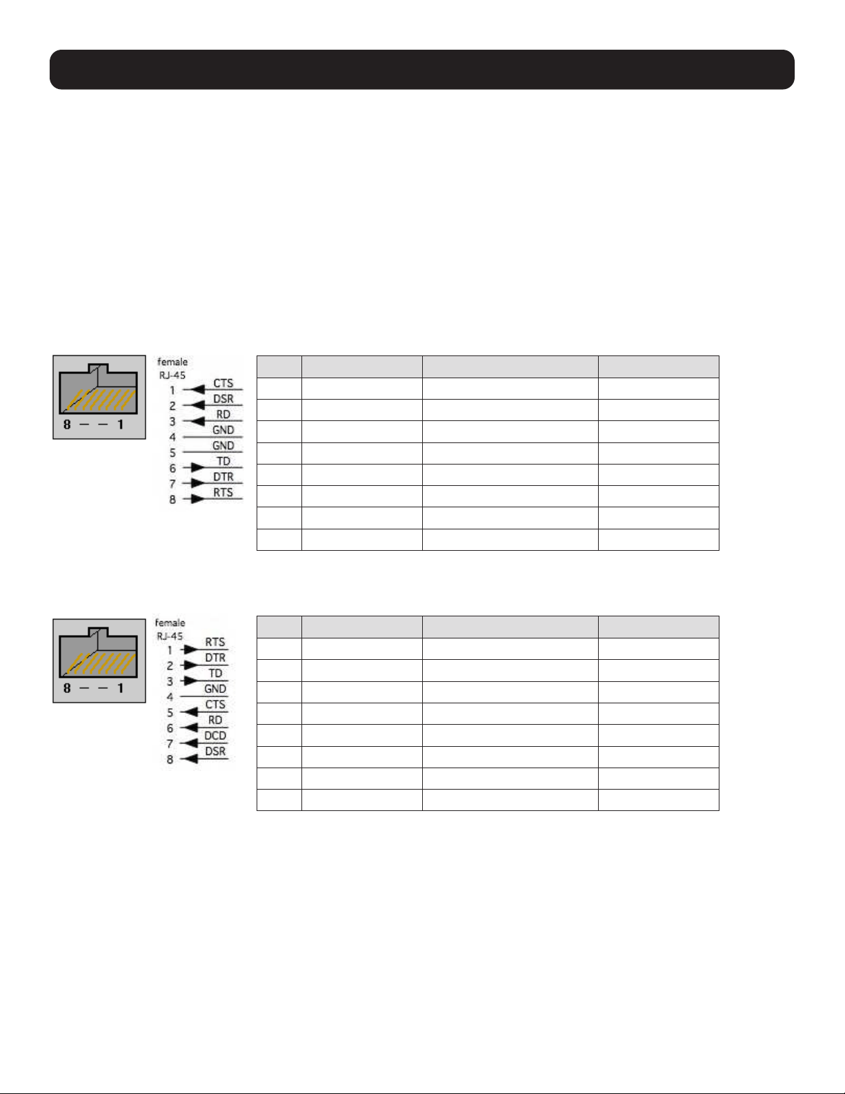
274
APPENDIX D: Connectivity, TCP Ports and Serial I/O
Pin-out standards exist for both DB9 and DB25 connectors. However, there are no pinout standards for serial connectivity
using RJ45 connectors. Most console servers and serially managed servers / routers / switches / power devices have adopted
their own unique pinout, so custom connectors and cables may be required to interconnect your console server.
Serial Port Pinout
Console servers come with one to forty eight serial connectors (notated SERIAL or SERIAL PORTS) for the RS-232 serial ports:
• The RJ45 serial ports are on the rear panel of the rack mount B098 and B097.
• The B093 and B097 models have Cisco Straight serial pinouts on its RJ45 connectors.
• The B098 has software selectable Cisco Straight or Cisco Rolled RJ45
Cisco Straight RJ45 pinout (option -X2)
Straight-through RJ45 cable to equipment such as Cisco, Juniper, SUN, and more.
Cisco Rolled RJ45 pinout (option -X1)
Easy to replace Avocent/Cyclades products, for use with rolled RJ-45 cable.
PIN SIGNAL DEFINITION DIRECTION
1 CTS Clear To Send Input
2 DSR Data Set Ready Input
3 RXD Receive Data Input
4 GND Signal Ground NA
5 GND Signal Ground NA
6 TXD Transmit Data Output
7 DTR Data Terminal Ready Output
8 RTS Request To Send Output
PIN SIGNAL DEFINITION DIRECTION
1 RTS Request To Send Output
2 DTR Data Terminal Ready Output
3 TXD Transmit Data Output
4 GND Signal Ground NA
5 CTS Clear To Send Input
6 RXD Receive Data Input
7 DCD Data Carrier Detect Input
8 DSR Data Set Ready Input

275
APPENDIX D: Connectivity, TCP Ports and Serial I/O
Local Console Port
The LOCAL (console/modem) port on the Console Server uses a standard DB9 connector as tabled below:
RS-232 Standard Pinouts
The RS-232 pinout standards for the DB9 connectors are:
SIGNAL DB9 DEFINITION
TXD 3 Transmitted Data
RXD 2 Received Data
RTS 7 Request To Send
CTS 8 Clear To Send
DSR 6 Data Set Ready
GND 5 Signal Ground
CD 1 Received Line Signal Detector
DTR 4 Data Terminal Ready
RI 9 Ring Indicator
FEMALE MALE
9 pin DB9
8 pin RJ45
Connectors Included with Console Server
DB9F-RJ45S straight connector

276
APPENDIX D: Connectivity, TCP Ports and Serial I/O
DB9F-RJ45S cross-over connector
TCP/UDP Port Numbers
Port numbers are divided into three ranges: Well-Known Ports, Registered Ports and Dynamic and/or Private Ports. Well-
Known Ports are those from 0 through 1023. Registered Ports are those from 1024 through 49151. Dynamic and/or Private
Ports are those from 49152 through 65535.
Well-Known Ports are assigned by IANA. On most systems, they can only be used by system processes or by programs
executed by privileged users. The table below shows some of the well-known port numbers. For more details, visit the IANA
website: http://www.iana.org/assignments/port-numbers.
Port Number Protocol TCP/UDP
21 FTP (File Transfer Protocol) TCP
22 SSH (Secure Shell) TCP
23 Telnet TCP
25 SMTP (Simple Mail Transfer Protocol) TCP
37 Time TCP, UCP
39 RLP (Resource Location Protocol) UDP
49 TACACS, TACACS+ UDP
53 DNS UDP
67 BOOTP server UDP
68 BOOTP client UDP
v69 TFTP UDP
70 Gopher TCP
79 Finger TCP
80 HTTP TCP
110 POP3 TCP
119 NNTP (Network News Transfer Protocol) TCP
161/162 SNMP UDP
443 HTTPS TCP

277
APPENDIX E: Terminology
TERM MEANING
3G Third-generation cellular technology. The standards that determine 3G call for greater bandwidth
and higher speeds for cellular networks.
AES The Advanced Encryption Standard (AES) is a new block cipher standard to replace DES,
developed by NIST, the US National Institute of Standards and Technology. AES ciphers use
a 128-bit block and 128-, 192-, or 256-bit keys. The larger block size helps resist birthday
attacks, while the large key size prevents brute force attacks.
APN Access Point Name (APN) is used by carriers to identify an IP packet data network that a mobile
data user wants to communicate with and the type of wireless service.
Authentication SMTP (Simple Mail Transfer Protocol)
Authentication is the technique by which a process verifies that its communication partner is
who it is supposed to be and not an imposter. Authentication confirms that data is sent to the
intended recipient and assures the recipient that the data originated from the expected sender
and has not been altered on route.
BIOS Basic Input/Output System is the built-in software in a computer executed on startup (boot) that
determines what the computer can do without accessing programs from a disk. On PCs, the
BIOS contains all the code required to control the keyboard, display screen, disk drives, serial
communications, and a number of miscellaneous functions.
Bonding Ethernet Bonding or Failover is the ability to detect communication failure transparently and
switch from one LAN connection to another.
BOOTP Bootstrap Protocol. A protocol that allows a network user to automatically receive an IP address
and have an operating system boot without user interaction. BOOTP is the basis for the more
advanced DHCP.
Certificates A digitally signed statement that contains information about an entity and the entity's public
key, thus binding these two pieces of information together. A certificate is issued by a trusted
organization (or entity) called a Certification Authority (CA) after the CA has verified that the entity
is who it says it is.
Certificate Authority A Certificate Authority is a trusted third party, which certifies public keys that truly belong to their
claimed owners. It is a key part of any Public Key Infrastructure, since it allows users to trust that
a given public key is the one they wish to use, either to send a private message to its owner or to
verify the signature on a message sent by that owner.
Certificate Revocation List A list of certificates that have been revoked by the CA before they expired. This may be necessary
if the private key certificate has been compromised or if the holder of the certificate is denied the
ability to establish a connection to the console server.
CHAP Challenge-Handshake Authentication Protocol (CHAP) is used to verify a user's name and
password for PPP Internet connections. It is more secure than PAP, the other main authentication
protocol.
DES The Data Encryption Standard is a block cipher with 64-bit blocks and a 56-bit key.
DHCP Dynamic Host Configuration Protocol. A communications protocol that assigns IP addresses to
computers when they are connected to the network.
DNS Domain Name System allocates Internet domain names and translates them into IP addresses.
A domain name is a meaningful and easy to remember name for an IP address.
DUN Dial-Up Networking.
Encryption The technique for converting a readable message (plaintext) into apparently random material
(ciphertext) which cannot be read if intercepted. The proper decryption key is required to read
the message.
Ethernet A physical layer protocol based upon IEEE standards.
Firewall A network gateway device that protects a private network from users on other networks. A firewall
is usually installed to allow users on an intranet access to the public Internet without allowing
public Internet users access to the intranet.

278
APPENDIX E: Terminology
TERM MEANING
Gateway A machine that provides a route (or pathway) to the outside world.
Hub A network device that allows more than one computer to be connected as a LAN, usually using
UTP cabling.
Internet A worldwide system of computer networks - a public, cooperative, and self-sustaining network
of networks accessible to hundreds of millions of people worldwide. The Internet is technically
distinguished because it uses the TCP/IP set of protocols.
Intranet A private TCP/IP network within an enterprise.
IPMI Intelligent Platform Management Interface (IPMI) is a set of common interfaces to a computer
system that system administrators can use to monitor system health and manage the system.
The IPMI standard defines the protocols for interfacing with a service processor embedded into a
server platform.
Key lifetimes The length of time before keys are renegotiated.
LAN Local Area Network.
LDAP The Lightweight Directory Access Protocol (LDAP) is based on the X.500 standard, but
significantly simpler and more readily adapted to meet custom needs. The core LDAP
specifications are all defined in RFCs. LDAP is a protocol used to access information stored in an
LDAP server.
LED Light-Emitting Diode.
MAC address Every piece of Ethernet hardware has a unique number assigned to it called its MAC address.
Ethernet is used locally to connect the console server to the Internet, and it may share the local
network with many other devices. The MAC address is used by the local Internet router in order
to direct console server traffic to it rather than someone else in the local area. It is a 48-bit
number usually written as a series of 6 hexadecimal octets (e.g., 00:d0:cf:00:5b:da). A console
server has a MAC address listed on a label underneath the device.
MSCHAP Microsoft Challenge Handshake Authentication Protocol (MSCHAP) is authentication for PPP
connections between a computer using a Microsoft Windows operating system and a network
access server. It is more secure than PAP or CHAP, and is the only option that also supports data
encryption.
NAT Network Address Translation. The translation of an IP address used on one network to an IP
address on another network. Masquerading is one particular form of NAT.
Net mask The way that computers know which part of a TCP/IP address refers to the network, and which
part refers to the host range.
NFS Network File System is a protocol that allows file sharing across a network. Users can view, store,
and update files on a remote computer.
NTP Network Time Protocol (NTP) used to synchronize clock times in a network of computers.
OUT OF BAND Out-of-Band (OOB) management is any management done over channels and interfaces that are
separate from those used for user/customer data. Examples include a serial console interface
or a network interface connected to a dedicated management network that is not used to carry
customer traffic, or to a BMC/service processor. Any management done over the same channels
and interfaces used for user/customer data is In Band.
PAP Password Authentication Protocol (PAP) is the usual method of user authentication used on the
internet: sending a username and password to a server where they are compared with a table of
authorized users. Whilst most common, PAP is the least secure of the authentication options.
PPP Point-to-Point Protocol. A networking protocol for establishing simple links between two peers.
RADIUS The Remote Authentication Dial-In User Service (RADIUS) protocol was developed by Livingston
Enterprises as an access server authentication and accounting protocol. The RADIUS server
can support a variety of methods to authenticate a user. When it is provided with the username
and original password given by the user, it can support PPP, PAP or CHAP, UNIX login, and other
authentication mechanisms.

279
TERM MEANING
Router A network device that moves packets of data. A router differs from hubs and switches because it
is "intelligent" and can route packets to their final destination.
SIM Subscriber Identity Module (SIM) card stores unique serial numbers and security authentication
used to identify a subscriber on mobile telephony devices.
SMASH Systems Management Architecture for Server Hardware is a standards-based protocols aimed
at increasing productivity of the management of a data center. The SMASH Command Line
Protocol (SMASH CLP) specification provides an intuitive interface to heterogeneous servers
independent of machine state, operating system or OS state, system topology or access method.
It is a standard method for local and remote management of server hardware using out-of-band
communication.
SMTP Simple Mail Transfer Protocol. The console server includes SMTPclient, a minimal SMTP client
that takes an email message body and passes it on to an SMTP server (default is the MTA on the
local host).
SOL Serial Over LAN (SOL) enables servers to transparently redirect the serial character stream from
the baseboard universal asynchronous receiver/transmitter (UART) to and from the remote-client
system over a LAN. With SOL support and BIOS redirection (to serial), remote managers can view
the BIOS/POST output when powered on and reconfigured.
SSH Secure Shell is secure transport protocol based on public-key cryptography.
SSL Secure Sockets Layer is a protocol that provides authentication and encryption services between
a web server and a web browser.
TACACS+ The Terminal Access Controller Access Control System (TACACS+) security protocol is a more
recent protocol developed by Cisco. It provides detailed accounting information and flexible
administrative control over the authentication and authorization processes. TACACS+ allows for
a single access control server (the TACACS+ daemon) to provide authentication, authorization,
and accounting services independently. Each service can be tied into its own database to
take advantage of other services available on that server or on the network, depending on the
capabilities of the daemon. There is a draft RFC detailing this protocol.
TCP/IP Transmission Control Protocol/Internet Protocol. The basic protocol for Internet communication.
TCP/IP address Fundamental Internet addressing method that uses the form nnn.nnn.nnn.nnn.
Telnet Telnet is a terminal protocol that provides an easy-to-use method of creating terminal
connections to a network.
UDP User Datagram Protocol.
UTC Coordinated Universal Time.
UTP Unshielded Twisted Pair cabling. A type of Ethernet cable that can operate up to 100Mb/s. Also
known as Category 5 or Cat5.
VNC Virtual Network Computing (VNC) is a desktop protocol to remotely control another computer.
It transmits the keyboard presses and mouse clicks from one computer to another, relaying the
screen updates back in the other direction and over a network.
VPN Virtual Private Network (VPN) is a network that uses a public telecommunication infrastructure
and Internet to provide remote offices or individual users with secure access to their
organization's network.
WAN Wide Area Network.
WINS Windows Internet Naming Service (WINS) manages the association of workstation names and
locations with IP addresses.
APPENDIX E: Terminology

280
APPENDIX F: End User License Agreements
READ BEFORE USING THE ACCOMPANYING SOFTWARE
CAREFULLY READ THE FOLLOWING TERMS AND CONDITIONS BEFORE USING THE ACCOMPANYING SOFTWARE, THE USE OF
WHICH IS LICENSED FOR USE ONLY AS SET FORTH BELOW. IF YOU DO NOT AGREE TO THE TERMS AND CONDITIONS OF THIS
AGREEMENT, DO NOT USE THE SOFTWARE. IF YOU USE ANY PART OF THE SOFTWARE, SUCH USE WILL INDICATE THAT YOU
ACCEPT THESE TERMS.
You have acquired a product that includes Tripp LIte (“Tripp LIte”) proprietary software and/or proprietary software licensed to
Tripp LIte. This Tripp LIte End User License Agreement (“EULA”) is a legal agreement between you (either an individual or a
single entity) and Tripp LIte for the installed software product of Tripp LIte origin, as well as associated media, printed materials,
and “online” or electronic documentation (“Software”). By installing, copying, downloading, accessing, or otherwise using the
Software, you agree to be bound by the terms of this EULA. If you do not agree to the terms of this EULA, Tripp LIte is not willing
to license the Software to you. In such event, do not use or install the Software. If you have purchased the Software, promptly
return the Software and all accompanying materials with proof of purchase for a refund.
Products with separate end user license agreements that may be provided along with the Software are licensed to you under the
terms of those separate end user license agreements.
LICENSE GRANT. Subject to the terms and conditions of this EULA, Tripp LIte grants you a nonexclusive right and license to install
and use the Software on a single CPU, provided that, (1) you may not rent, lease, sell, sublicense or lend the Software; (2) you
may not reverse engineer, decompile, disassemble or modify the Software, except and only to the extent that such activity is
expressly permitted by applicable law notwithstanding this limitation; and (3) you may not transfer rights under this EULA unless
such transfer is part of a permanent sale or transfer of the Product, you transfer at the same time all copies of the Software to
the same party or destroy such materials not transferred, and the recipient agrees to this EULA.
No license is granted in any of the Software’s proprietary source code. This license does not grant you any rights to patents,
copyright, trade secrets, trademarks or any other rights with respect to the Software.
You may make a reasonable number of copies of the electronic documentation accompanying the Software for each Software
license you acquire, provided that, you must reproduce and include all copyright notices and any other proprietary rights notices
appearing on the electronic documentation. Tripp LIte reserves all rights not expressly granted herein.
INTELLECTUAL PROPERTY RIGHTS. The Software is protected by copyright laws, international copyright treaties, and other
intellectual property laws and treaties. Tripp LIte and its suppliers retain all ownership of, and intellectual property rights in
(including copyright), the Software components and all copies thereof, provided however, that (1) certain components of the
Software, including SDT Connector, are components licensed under the GNU General Public License Version 2, which Tripp LIte
supports, and (2) the SDT Connector includes code from JSch, a pure Java implementation of SSH2 which is licensed under
BSD style license. Copies of these licenses are detailed below and Tripp LIte will provide source code for any of the components
of the Software licensed under the GNU General Public License upon request.
EXPORT RESTRICTIONS. You agree that you will not export or re-export the Software, any part thereof, or any process or service
that is the direct product of the Software in violation of any applicable laws or regulations of the United States or the country in
which you obtained them.
U.S. GOVERNMENT RESTRICTED RIGHTS. The Software and related documentation are provided with Restricted Rights. Use,
duplication, or disclosure by the Government is subject to restrictions set forth in subparagraph (c) (1) (ii) of the Rights in
Technical Data and Computer Software clause at DFARS 252.227-7013 or subparagraphs (c) (1) and (2) of the Commercial
Computer Software – Restricted Rights at 48 C.F.R. 52.227-19, as applicable, or any successor regulations.
TERM AND TERMINATION. This EULA is effective until terminated. The EULA terminates immediately if you fail to comply with any
term or condition. In such an event, you must destroy all copies of the Software. You may also terminate this EULA at any time
by destroying the Software.
GOVERNING LAW AND ATTORNEY’S FEES. This EULA is governed by the laws of the State of Utah, USA, excluding its conflict of
law rules. You agree that the United Nations Convention on Contracts for the International Sale of Goods is hereby excluded in its
entirety and does not apply to this EULA. If you acquired this Software in a country outside of the United States, that country’s
laws may apply. In any action or suit to enforce any right or remedy under this EULA or to interpret any provision of this EULA,
the prevailing party will be entitled to recover its costs, including reasonable attorneys’ fees.
ENTIRE AGREEMENT. This EULA constitutes the entire agreement between you and Tripp LIte with respect to the Software, and
supersedes all other agreements or representations, whether written or oral. The terms of this EULA can only be modified by
express written consent of both parties. If any part of this EULA is held to be unenforceable as written, it will be enforced to the
maximum extent allowed by applicable law, and will not affect the enforceability of any other part.

281
APPENDIX F: End User License Agreements
Should you have any questions concerning this EULA, or if you desire to contact Tripp LIte for any reason, please contact the
Tripp LIte representative serving your company.
THE FOLLOWING DISCLAIMER OF WARRANTY AND LIMITATION OF LIABILITY IS INCORPORATED INTO THIS EULA BY REFERENCE.
THE SOFTWARE IS NOT FAULT TOLERANT. YOU HAVE INDEPENDENTLY DETERMINED HOW TO USE THE SOFTWARE IN THE
DEVICE, AND TRIPP LITE HAS RELIED UPON YOU TO CONDUCT SUFFICIENT TESTING TO DETERMINE THAT THE SOFTWARE IS
SUITABLE FOR SUCH USE.
LIMITED WARRANTY Tripp LIte warrants the media containing the Software for a period of ninety (90) days from the date of
original purchase from Tripp LIte or its authorized retailer. Proof of date of purchase will be required. Any updates to the Software
provided by Tripp LIte (which may be provided by Tripp LIte at its sole discretion) shall be governed by the terms of this EULA.
In the event the product fails to perform as warranted, Tripp LIte’s sole obligation shall be, at Tripp LIte’s discretion, to refund
the purchase price paid by you for the Software on the defective media, or to replace the Software on new media. Tripp LIte
makes no warranty or representation that its Software will meet your requirements, will work in combination with any hardware
or application software products provided by third parties, that the operation of the software products will be uninterrupted or
error free, or that all defects in the Software will be corrected.
TRIPP LITE DISCLAIMS ANY AND ALL OTHER WARRANTIES, WHETHER EXPRESS OR IMPLIED, INCLUDING WITHOUT LIMITATION,
ANY IMPLIED WARRANTIES OF MERCHANTABILITY OR FITNESS FOR A PARTICULAR PURPOSE. OTHER THAN AS STATED HEREIN,
THE ENTIRE RISK AS TO SATISFACTORY QUALITY, PERFORMANCE, ACCURACY, AND EFFORT IS WITH YOU. ALSO, THERE IS NO
WARRANTY AGAINST INTERFERENCE WITH YOUR ENJOYMENT OF THE SOFTWARE OR AGAINST INFRINGEMENT. IF YOU HAVE
RECEIVED ANY WARRANTIES REGARDING THE DEVICE OR THE SOFTWARE, THOSE WARRANTIES DO NOT ORIGINATE FROM,
AND ARE NOT BINDING ON, TRIPP LITE.
NO LIABILITY FOR CERTAIN DAMAGES. EXCEPT AS PROHIBITED BY LAW, TRIPP LITE SHALL HAVE NO LIABILITY FOR COSTS,
LOSS, DAMAGES OR LOST OPPORTUNITY OF ANY TYPE WHATSOEVER, INCLUDING BUT NOT LIMITED TO, LOST OR ANTICIPATED
PROFITS, LOSS OF USE, LOSS OF DATA, OR ANY INCIDENTAL, EXEMPLARY SPECIAL OR CONSEQUENTIAL DAMAGES, WHETHER
UNDER CONTRACT, TORT, WARRANTY OR OTHERWISE ARISING FROM OR IN CONNECTION WITH THIS EULA OR THE USE OR
PERFORMANCE OF THE SOFTWARE. IN NO EVENT SHALL TRIPP LITE BE LIABLE FOR ANY AMOUNT IN EXCESS OF THE LICENSE
FEE PAID TO TRIPP LITE UNDER THIS EULA. SOME STATES AND COUNTRIES DO NOT ALLOW THE LIMITATION OR EXCLUSION OF
LIABILITY FOR INCIDENTAL OR CONSEQUENTIAL DAMAGES, SO THIS LIMITATION MAY NOT APPLY TO YOU.
JSch License
SDT Connector includes code from JSch, a pure Java implementation of SSH2. JSch is licensed under BSD style license and is:
Copyright (c) 2002, 2003, 2004 Atsuhiko Yamanaka, JCraft,Inc. All rights reserved.
Redistribution and use in source and binary forms, with or without modification, are permitted provided that the following
conditions are met:
1. Redistributions of source code must retain the above copyright notice, this list of conditions and the following disclaimer.
2. Redistributions in binary form must reproduce the above copyright notice, this list of conditions and the following disclaimer
in the documentation and/or other materials provided with the distribution.
3. The names of the authors may not be used to endorse or promote products derived from this software without specific prior
written permission.
THIS SOFTWARE IS PROVIDED ``AS IS’’ AND ANY EXPRESSED OR IMPLIED WARRANTIES, INCLUDING, BUT NOT LIMITED TO,
THE IMPLIED WARRANTIES OF MERCHANTABILITY AND FITNESS FOR A PARTICULAR PURPOSE ARE DISCLAIMED. IN NO EVENT
SHALL JCRAFT, INC. OR ANY CONTRIBUTORS TO THIS SOFTWARE BE LIABLE FOR ANY DIRECT, INDIRECT, INCIDENTAL, SPECIAL,
EXEMPLARY, OR CONSEQUENTIAL DAMAGES (INCLUDING, BUT NOT LIMITED TO, PROCUREMENT OF SUBSTITUTE GOODS OR
SERVICES; LOSS OF USE, DATA, OR PROFITS; OR BUSINESS INTERRUPTION) HOWEVER CAUSED AND ON ANY THEORY OF
LIABILITY, WHETHER IN CONTRACT, STRICT LIABILITY, OR TORT (INCLUDING NEGLIGENCE OR OTHERWISE) ARISING IN ANY WAY
OUT OF THE USE OF THIS SOFTWARE, EVEN IF ADVISED OF THE POSSIBILITY OF SUCH DAMAGE.

282
APPENDIX F: End User License Agreements
GNU GENERAL PUBLIC LICENSE
Version 2, June 1991
Copyright (C) 1989, 1991 Free Software Foundation, Inc.
51 Franklin Street, Fifth Floor, Boston, MA 02110-1301, USA
Everyone is permitted to copy and distribute verbatim copies of this license document, but changing it is not allowed.
GNU GENERAL PUBLIC LICENSE
TERMS AND CONDITIONS FOR COPYING, DISTRIBUTION AND MODIFICATION
0. This License applies to any program or other work which contains a notice placed by the copyright holder saying it may be
distributed under the terms of this General Public License. The “Program”, below, refers to any such program or work, and a “work
based on the Program” means either the Program or any derivative work under copyright law: that is to say, a work containing the
Program or a portion of it, either verbatim or with modifications and/or translated into another language. (Hereinafter, translation
is included without limitation in the term “modification”.) Each licensee is addressed as “you”.
Activities other than copying, distribution and modification are not covered by this License; they are outside its scope. The act
of running the Program is not restricted, and the output from the Program is covered only if its contents constitute a work based
on the Program (independent of having been made by running the Program). Whether that is true depends on what the Program
does.
1. You may copy and distribute verbatim copies of the Program’s source code as you receive it, in any medium, provided that you
conspicuously and appropriately publish on each copy an appropriate copyright notice and disclaimer of warranty; keep intact all
the notices that refer to this License and to the absence of any warranty; and give any other recipients of the Program a copy of
this License along with the Program.
You may charge a fee for the physical act of transferring a copy, and you may at your option offer warranty protection in exchange
for a fee.
2. You may modify your copy or copies of the Program or any portion of it, thus forming a work based on the Program, and copy
and distribute such modifications or work under the terms of Section 1 above, provided that you also meet all of these conditions:
a) You must cause the modified files to carry prominent notices stating that you changed the files and the date of any
change.
b) You must cause any work that you distribute or publish, that in whole or in part contains or is derived from the Program
or any part thereof, to be licensed as a whole at no charge to all third parties under the terms of this License.
c) If the modified program normally reads commands interactively when run, you must cause it, when started running for
such interactive use in the most ordinary way, to print or display an announcement including an appropriate copyright notice
and a notice that there is no warranty (or else, saying that you provide a warranty) and that users may redistribute the
program under these conditions, and telling the user how to view a copy of this License. (Exception: if the Program itself
is interactive but does not normally print such an announcement, your work based on the Program is not required to print
an announcement.)
These requirements apply to the modified work as a whole. If identifiable sections of that work are not derived from the Program,
and can be reasonably considered independent and separate works in themselves, then this License, and its terms, do not apply
to those sections when you distribute them as separate works. But when you distribute the same sections as part of a whole
which is a work based on the Program, the distribution of the whole must be on the terms of this License, whose permissions for
other licensees extend to the entire whole, and thus to each and every part regardless of who wrote it.
Thus, it is not the intent of this section to claim rights or contest your rights to work written entirely by you; rather, the intent is
to exercise the right to control the distribution of derivative or collective works based on the Program.
In addition, mere aggregation of another work not based on the Program with the Program (or with a work based on the Program)
on a volume of a storage or distribution medium does not bring the other work under the scope of this License.

283
APPENDIX F: End User License Agreements
3. You may copy and distribute the Program (or a work based on it, under Section 2) in object code or executable form under
the terms of Sections 1 and 2 above provided that you also do one of the following:
a) Accompany it with the complete corresponding machine-readable source code, which must be distributed under the
terms of Sections 1 and 2 above on a medium customarily used for software interchange; or,
b) Accompany it with a written offer, valid for at least three years, to give any third party, for a charge no more than your
cost of physically performing source distribution, a complete machine-readable copy of the corresponding source code,
to be distributed under the terms of Sections 1 and 2 above on a medium customarily used for software interchange; or,
c) Accompany it with the information you received as to the offer to distribute corresponding source code. (This alternative
is allowed only for noncommercial distribution and only if you received the program in object code or executable form with
such an offer, in accord with Subsection b above).
The source code for a work means the preferred form of the work for making modifications to it. For an executable work, complete
source code means all the source code for all modules it contains, plus any associated interface definition files, plus the scripts
used to control compilation and installation of the executable. However, as a special exception, the source code distributed need
not include anything that is normally distributed (in either source or binary form) with the major components (compiler, kernel,
and so on) of the operating system on which the executable runs, unless that component itself accompanies the executable.
If distribution of executable or object code is made by offering access to copy from a designated place, then offering equivalent
access to copy the source code from the same place counts as distribution of the source code, even though third parties are not
compelled to copy the source along with the object code.
4. You may not copy, modify, sublicense, or distribute the Program except as expressly provided under this License. Any attempt
otherwise to copy, modify, sublicense or distribute the Program is void, and will automatically terminate your rights under this
License. However, parties who have received copies, or rights, from you under this License will not have their licenses terminated
so long as such parties remain in full compliance.
5. You are not required to accept this License, since you have not signed it. However, nothing else grants you permission to
modify or distribute the Program or its derivative works. These actions are prohibited by law if you do not accept this License.
Therefore, by modifying or distributing the Program (or any work based on the Program), you indicate your acceptance of this
License to do so, and all its terms and conditions for copying, distributing or modifying the Program or works based on it.
6. Each time you redistribute the Program (or any work based on the Program), the recipient automatically receives a license
from the original licensor to copy, distribute or modify the Program subject to these terms and conditions. You may not impose
any further restrictions on the recipients’ exercise of the rights granted herein. You are not responsible for enforcing compliance
by third parties to this License.
7. If, as a consequence of a court judgment or allegation of patent infringement or for any other reason (not limited to patent
issues), conditions are imposed on you (whether by court order, agreement or otherwise) that contradict the conditions of this
License, they do not excuse you from the conditions of this License. If you cannot distribute so as to satisfy simultaneously your
obligations under this License and any other pertinent obligations, then as a consequence you may not distribute the Program
at all. For example, if a patent license would not permit royalty-free redistribution of the Program by all those who receive copies
directly or indirectly through you, then the only way you could satisfy both it and this License would be to refrain entirely from
distribution of the Program.
If any portion of this section is held invalid or unenforceable under any particular circumstance, the balance of the section is
intended to apply and the section as a whole is intended to apply in other circumstances.
It is not the purpose of this section to induce you to infringe any patents or other property right claims or to contest validity of
any such claims; this section has the sole purpose of protecting the integrity of the free software distribution system, which
is implemented by public license practices. Many people have made generous contributions to the wide range of software
distributed through that system in reliance on consistent application of that system; it is up to the author/donor to decide if he
or she is willing to distribute software through any other system and a licensee cannot impose that choice.
This section is intended to make thoroughly clear what is believed to be a consequence of the rest of this License.
8. If the distribution and/or use of the Program is restricted in certain countries either by patents or by copyrighted interfaces,
the original copyright holder who places the Program under this License may add an explicit geographical distribution limitation
excluding those countries, so that distribution is permitted only in or among countries not thus excluded. In such case, this
License incorporates the limitation as if written in the body of this License.

284
APPENDIX F: End User License Agreements
9. The Free Software Foundation may publish revised and/or new versions of the General Public License from time to time. Such
new versions will be similar in spirit to the present version, but may differ in detail to address new problems or concerns.
Each version is given a distinguishing version number. If the Program specifies a version number of this License which applies to
it and “any later version”, you have the option of following the terms and conditions either of that version or of any later version
published by the Free Software Foundation. If the Program does not specify a version number of this License, you may choose
any version ever published by the Free Software Foundation.
10. If you wish to incorporate parts of the Program into other free programs whose distribution conditions are different, write to
the author to ask for permission. For software which is copyrighted by the Free Software Foundation, write to the Free Software
Foundation; we sometimes make exceptions for this. Our decision will be guided by the two goals of preserving the free status
of all derivatives of our free software and of promoting the sharing and reuse of software generally.
NO WARRANTY
11. BECAUSE THE PROGRAM IS LICENSED FREE OF CHARGE, THERE IS NO WARRANTY FOR THE PROGRAM, TO THE EXTENT
PERMITTED BY APPLICABLE LAW. EXCEPT WHEN OTHERWISE STATED IN WRITING THE COPYRIGHT HOLDERS AND/OR OTHER
PARTIES PROVIDE THE PROGRAM “AS IS” WITHOUT WARRANTY OF ANY KIND, EITHER EXPRESSED OR IMPLIED, INCLUDING, BUT
NOT LIMITED TO, THE IMPLIED WARRANTIES OF MERCHANTABILITY AND FITNESS FOR A PARTICULAR PURPOSE. THE ENTIRE
RISK AS TO THE QUALITY AND PERFORMANCE OF THE PROGRAM IS WITH YOU. SHOULD THE PROGRAM PROVE DEFECTIVE,
YOU ASSUME THE COST OF ALL NECESSARY SERVICING, REPAIR OR CORRECTION.
12. IN NO EVENT UNLESS REQUIRED BY APPLICABLE LAW OR AGREED TO IN WRITING WILL ANY COPYRIGHT HOLDER, OR
ANY OTHER PARTY WHO MAY MODIFY AND/OR REDISTRIBUTE THE PROGRAM AS PERMITTED ABOVE, BE LIABLE TO YOU FOR
DAMAGES, INCLUDING ANY GENERAL, SPECIAL, INCIDENTAL OR CONSEQUENTIAL DAMAGES ARISING OUT OF THE USE OR
INABILITY TO USE THE PROGRAM (INCLUDING BUT NOT LIMITED TO LOSS OF DATA OR DATA BEING RENDERED INACCURATE OR
LOSSES SUSTAINED BY YOU OR THIRD PARTIES OR A FAILURE OF THE PROGRAM TO OPERATE WITH ANY OTHER PROGRAMS),
EVEN IF SUCH HOLDER OR OTHER PARTY HAS BEEN ADVISED OF THE POSSIBILITY OF SUCH DAMAGES.

285
APPENDIX G: Service and Limited Warranty
Service
Your Tripp Lite product is covered by the warranty described in this manual. A variety of Extended Warranty and On-Site Service
Programs are also available from Tripp Lite. For more information on service, visit www.tripplite.com/support. Before returning
your product for service, follow these steps:
Review the installation and operation procedures in this manual to insure that the service problem does not originate from a
misreading of the instructions.
If the problem continues, do not contact or return the product to the dealer. Instead, visit www.tripplite.com/support.
If the problem requires service, visit www.tripplite.com/support and click the Product Returns link. From here you can request
a Returned Material Authorization (RMA) number, which is required for service. This simple on-line form will ask for your unit’s
model and serial numbers, along with other general purchaser information. The RMA number, along with shipping instructions
will be emailed to you. Any damages (direct, indirect, special or consequential) to the product incurred during shipment
to Tripp Lite or an authorized Tripp Lite service center is not covered under warranty. Products shipped to Tripp Lite or an
authorized Tripp Lite service center must have transportation charges prepaid. Mark the RMA number on the outside of the
package. If the product is within its warranty period, enclose a copy of your sales receipt. Return the product for service using
an insured carrier to the address given to you when you request the RMA.
4-Year Limited Warranty
TRIPP LITE warrants its products to be free from defects in materials and workmanship for a period of two (4) years from the
date of initial purchase. TRIPP LITE’s obligation under this warranty is limited to repairing or replacing (at its sole option) any
such defective products. To obtain service under this warranty, you must obtain a Returned Material Authorization (RMA)
number from TRIPP LITE or an authorized TRIPP LITE service center. Products must be returned to TRIPP LITE or an authorized
TRIPP LITE service center with transportation charges prepaid and must be accompanied by a brief description of the problem
encountered and proof of date and place of purchase. This warranty does not apply to equipment which has been damaged by
accident, negligence or misapplication or has been altered or modifed in any way.
EXCEPT AS PROVIDED HEREIN, TRIPP LITE MAKES NO WARRANTIES, EXPRESS OR IMPLIED, INCLUDING WARRANTIES OF
MERCHANTABILITY AND FITNESS FOR A PARTICULAR PURPOSE. Some states do not permit limitation or exclusion of implied
warranties; therefore, the aforesaid limitation(s) or exclusion(s) may not apply to the purchaser.
EXCEPT AS PROVIDED ABOVE, IN NO EVENT WILL TRIPP LITE BE LIABLE FOR DIRECT, INDIRECT, SPECIAL, INCIDENTAL OR
CONSEQUENTIAL DAMAGES ARISING OUT OF THE USE OF THIS PRODUCT, EVEN IF ADVISED OF THE POSSIBILITY OF SUCH
DAMAGE. Specifically, TRIPP LITE is not liable for any costs, such as lost profits or revenue, loss of equipment, loss of use of
equipment, loss of software, loss of data, costs of substitutes, claims by third parties, or otherwise.
Tripp Lite has a policy of continuous improvement. Specifications are subject to change without notice. Photos and illustrations
may differ slightly from actual products.
22-01-216 93-38A8_RevC
1111 W. 35th Street, Chicago, IL 60609 USA • tripplite.com/support