Loading ...
Loading ...
Loading ...
C
ASSEMBLY/ADJUSTMENT
SET-UP
CAUTION: To reduce the risk of
injury, turn off and unplug the tool before
making any adjustments or removing or
installing attachments or accessories.
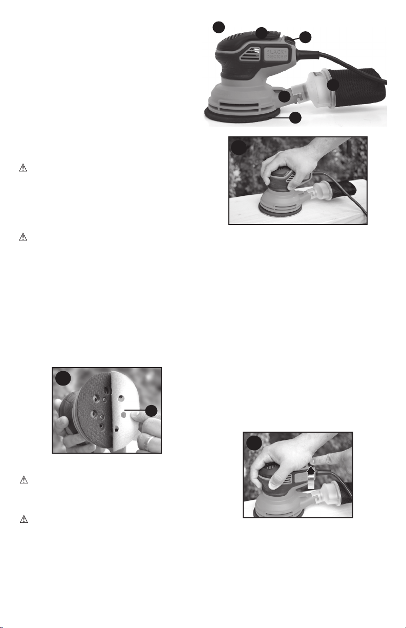
ATTACHING HOOK AND LOOP
SANDING DISCS (FIGURE B)
WARNING: To avoid injury, lock the
sander off during sanding disc installation.
Refer to “Lock Off” section.
extraction pattern. For best results, use
accessories.
center it over the sanding pad (3) ensuring
the holes in the disc align with the holes in
the pad and press the disc firmly in place.
disc can be easily removed by simply pulling
it off. It can be reused as desired.
OPERATING INSTRUCTIONS
WARNING: To reduce the risk of
serious personal injury, read, understand
and follow all important safety warnings and
instructions prior to using this tool.
WARNING: Shock hazard. Under no
circumstances should this product be used
near water.
ON/OFF
Figure C
and squeeze so the paddle (1) depresses
without putting pressure on the workpiece
OFF, release the paddle.
OPERATION
Grasp the sander and turn it ON. Move it in
long, sweeping strokes along the surface,
letting it do the work. Pushing down on the
tool while sanding actually slows the removal
rate and produces an inferior quality finish.
Check your work often. This sander is
capable of removing material rapidly.
LOCK-ON / LOCK-OFF SLIDER
This sander is equipped with a switch that
allows you to lock it on for extended use,
and lock off to prevent accidental actuation.
LOCK ON
ON, depress the paddle
(1) with one hand and push the slider (2)
right to the locked position with your other
hand as shown in Figure D.
unlocked position and release paddle.
LOCK OFF
paddle (1) is not depressed and push the
slider (2) right to the locked position. The
paddle cannot be depressed while switch
is in locked position.
to the unlocked position. The paddle can
now be depressed.
B
6
D
FUNCTIONAL DESCRIPTION
Figure A
1. On / off paddle
3. Sanding pad
4. Dust port
1
A
5
4
2
3
Loading ...
Loading ...
Loading ...