All information in this Owner’s Manual is current at the time
of publication. However, Genesis reserves the right to make
changes at any time so that our policy of continual product
improvement may be carried out.
This manual applies to all Genesis Branded Vehicle models and
includes descriptions and explanations of optional as well as
standard equipment.
As a result, you may find material in this manual that does not
apply to your specific vehicle.
OWNER’S MANUAL
Operation
Maintenance
Specifications

F2
Introduction
Your Genesis Branded Vehicle should not be modified in any way. Such
modifications may adversely affect the performance, safety or durability of your
Genesis Branded Vehicle and may, in addition, violate conditions of the limited
warranties covering the vehicle. Certain modifications may also be in violation
of regulations established by the U.S. Department of Transportation and other
federal or state agencies.
Your vehicle is equipped with a Tire Pressure Monitoring System, Passenger
Occupant Classification System and other CAN bus systems. It is possible for
an improperly installed/adjusted high powered two-way radio to adversely
affect electronic systems. For this reason, we recommend that you carefully
follow the radio manufacturer’s instructions if you choose to install one of these
devices.
CAUTION: MODIFICATIONS TO YOUR
GENESIS BRANDED VEHICLE
T:OǢ:AY RADIO INSTALLATION

F3
This manual includes information titled as DANGER, WARNING, CAUTION and
NOTICE.
These titles indicate the following:
DANGER
DANGER indicates a hazardous situation which, if not avoided, will result in
death or serious injury.
WARNING
WARNING indicates a hazardous situation which, if not avoided, could result
in death or serious injury.
CAUTION
CAUTION indicates a hazardous situation which, if not avoided, could result
in minor or moderate injury.
NOTICE
NOTICE indicates a situation which, if not avoided, could result in vehicle
damage.
SAFETY AND VEHICLE DAMAGE WARNING

F4
Introduction
Your Genesis Branded Vehicle may be equipped with technologies and services
that use information collected, generated, recorded or stored by the vehicle.
Genesis Branded Vehicle has created a Vehicle Owner Privacy Policy to explain
how these technologies and services collect use and share this information.
You may read our Vehicle Owner Privacy Policy at “http://www.genesis.com/
us/en/my-privacy-rights.html#owner”
http://www.genesismotorsusa.com/privacy-policy.html
If you would like to receive a hard copy of our Vehicle Owner Privacy Policy,
please contact our Genesis Customer Care at:
Genesis Customer Care
PO BOX 20650
Fountain Valley, CA 92728
844-340-9741
Genesis Customer Care Center representatives are available Monday through
Friday between the hours of 5:00 AM and 5:00 PM PST and Saturday between
6:30 AM and 3:00 PM PST (English).
For Genesis Customer Care assistance in Spanish or Korean, representatives are
available Monday through Friday between 6:30 AM and 3:00 PM PST.
GENESIS BRANDED VEHICLE OWNER PRIVACY
POLICY

1
2
3
4
5
6
7
9
I
8
Maintenance
Index
Emergency Situations
Driver Assistance System
Driving Your Vehicle
Convenience Features
Instrument Cluster, Armrest touchscreen,
Infotainment system
Safety System
Vehicle Information, Consumer Information and
Reporting Safety Defects
Introduction
Table of Contents

1
1. Introduction
Introduction.......................................................................................................1-2
Genesis Customer Care
.................................................................................... 1-2
Guide to Genesis Parts
..................................................................................... 1-3
How to Use this Manual
................................................................................... 1-4
Safety Messages
............................................................................................... 1-4
Fuel Requirements
............................................................................................ 1-5
Gasoline containing alcohol and methanol ............................................................. 1-5
Using Fuel Additives (except Detergent Fuel Additives)
......................................... 1-6
Gasoline containing MMT
......................................................................................... 1-6
Detergent Fuel Additives
........................................................................................... 1-6
Operation in foreign countries
.................................................................................. 1-6
Vehicle Modifications ....................................................................................... 1-7
Vehicle Break-in Process
.................................................................................. 1-7
Vehicle Data Collection and Event Data Recorders
....................................... 1-8

1-2
Introduction
INTRODUCTION
Congratulations, and thank you for choosing this Genesis Branded Vehicle. We are
pleased to welcome you to the growing number of discerning people who drive the
Genesis Branded Vehicle. We are very proud of the advanced engineering and high-
quality construction of each Genesis Branded Vehicle we build.
Your Owner’s Manual will introduce you to the features and operation of your new
Genesis Branded Vehicle. To become familiar with your new Genesis Branded Vehicle,
so that you can fully enjoy it, read this Owner’s Manual carefully before driving your
new vehicle.
This manual contains important safety information and instructions intended to
familiarize you with your vehicle’s controls and safety features so you can safely
operate your vehicle.
This manual also contains information on maintenance designed to enhance safe
operation of the vehicle. It is recommended that all service and maintenance on your
car be performed by an authorized retailer of Genesis Branded products. Retailers of
Genesis Branded products are prepared to provide high-quality service, maintenance
and any other assistance that may be required.
This Owner’s Manual should be considered a permanent part of your vehicle, and
should be kept in the vehicle so you can refer to it at any time. The manual should stay
with the vehicle if you sell it to provide the next owner with important operating, safety
and maintenance information.
GENESIS CUSTOMER CARE
CAUTION
Severe engine and transmission damage may result from the use of poor quality
fuels and lubricants that do not meet Genesis Branded Vehicle specifications. You
must always use high quality fuels and lubricants that meet the specifications listed
on Page 2-12 in the Vehicle Specifications section of the Owner’s Manual.
Copyright 2023 Genesis Customer Care. All rights reserved. No part of this publication
may be reproduced, stored in any retrieval system or transmitted in any form or by any
means without the prior written permission of Genesis Customer Care.
1-3
01
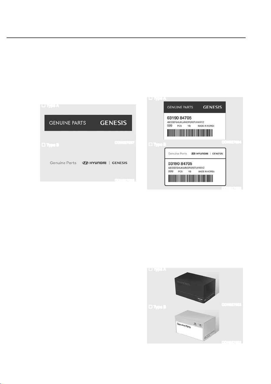
1. What are Genesis Parts?
Genesis Parts are the same parts
used by HYUNDAI Motor Company
to manufacture vehicles. They are
designed and tested for the optimum
safety, performance, and reliability to
our customers.
Type A
ODH027037
Type B
ODH027036
2. Why should you use Genesis Parts?
Genesis Parts are engineered and
built to meet rigid manufacturing
requirements. Damage caused by
using imitation, counterfeit or used
salvage parts is not covered under
the Genesis Branded New Vehicle
Limited Warranty or any other Genesis
Branded Vehicle warranty.
In addition, any damage to or failure
of Genesis Part caused by the
installation or failure of an imitation,
counterfeit or used salvage part is
not covered by any Genesis Branded
Vehicle Warranty.
Type A
ODH027034
Type B
ODH027035
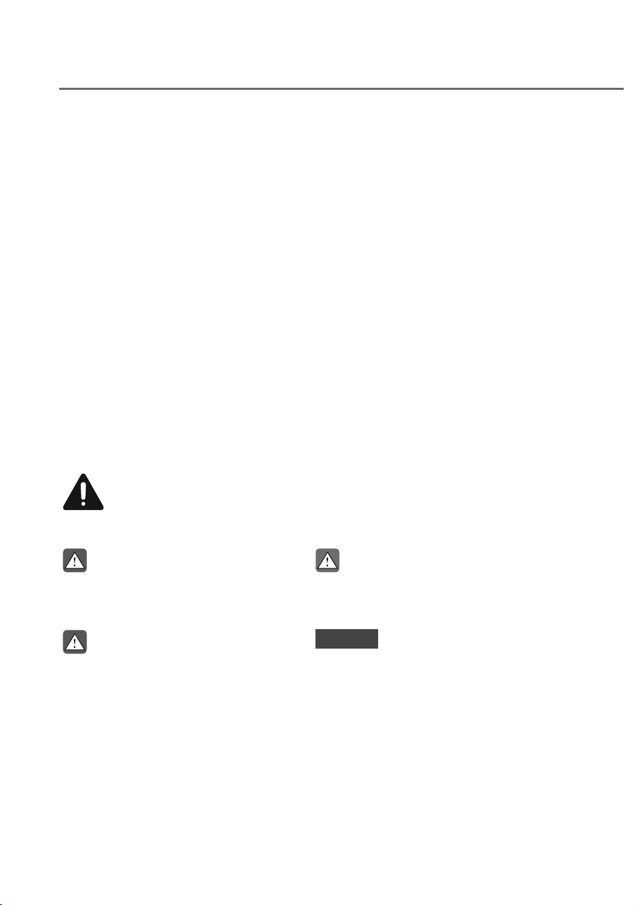
3. How can you tell if you are purchasing
Genesis Parts?
Look for the Genesis Parts Logo on the
package.
Genesis Parts exported to the U.S. are
packaged with labels written only in
English.
Genesis Parts are only sold through an
authorized retailer of Genesis Branded
products.
Type A
ODH027033
Type B
ODH027032
GUIDE TO GENESIS PARTS
1-4
Introduction
We want to help you get the greatest possible driving pleasure from your vehicle. Your
Owner’s Manual can assist you in many ways. To gain an overview of the contents
of your Owner’s Manual, use the Table of Contents in the front of the manual. The
first page of each Chapter includes a detailed Table of Contents of the topics in that
Chapter.
To quickly locate information about your vehicle, use the Index in the back of the
manual. It is an alphabetical list of what is in this manual and the page number where it
can be found.
For your convenience, we have incorporated tabs on the right-hand page edges.
These tabs are coded with the Chapter titles to assist you with navigating through the
manual.
SAFETY MESSAGES
Your safety, and the safety of others, is very important. This Owner’s Manual provides
you with many safety precautions and operating procedures. This information alerts
you to potential hazards that may hurt you or others, as well as damage your vehicle.
Safety messages found on vehicle labels and in this manual describe these hazards
and what to do to avoid or reduce the risks.
Warnings and instructions contained in this manual are for your safety. Failure to follow
safety warnings and instructions can lead to serious injury or death.
Throughout this manual DANGER, WARNING, CAUTION, NOTICE and the SAFETY
ALERT SYMBOL will be used.
This is the safety alert symbol. It is used to alert you to potential physical injury
hazards. Obey all safety messages that follow this symbol to avoid possible
injury or death. The safety alert symbol precedes the signal words DANGER,
DANGER
DANGER indicates a hazardous
situation which, if not avoided, will
result in death or serious injury.
WARNING
WARNING indicates a hazardous
situation which, if not avoided, could
result in death or serious injury.
CAUTION
CAUTION indicates a hazardous
situation which, if not avoided, could
result in minor or moderate injury.
NOTICE
NOTICE indicates a situation which,
if not avoided, could result in vehicle
damage.
HOW TO USE THIS MANUAL

1-5
01
Your new vehicle is designed to obtain maximum performance with UNLEADED FUEL,
as well as minimize exhaust emissions and spark plug fouling.
Your new vehicle is designed to use only unleaded fuel having an octane number
((R+M)/2) of 87 (Research Octane Number 91) or higher. For improved vehicle
performance, premium unleaded fuel with an octane number ((R+M)/2) of 91
(Research Octane Number 95) or higher is recommended. (Do not use methanol
blended fuels.)
NOTICE
To prevent damage to the engine and engine components, never add any fuel
system cleaning agents to the fuel tank other than what has been specified.
Consult an authorized retailer of Genesis Branded products for additional
information.
WARNING
ȉ Do not “top off” after the nozzle automatically shuts off when refueling.
ȉ Always check that the fuel cap is installed securely to prevent fuel spillage in the
event of an accident.
Gasoline containing alcohol and methanol
Gasohol, a mixture of gasoline and ethanol (also known as grain alcohol) are being
marketed along with or instead of leaded or unleaded gasoline. For example, “E15” is
a gasohol comprised of 15% ethanol and 85% gasoline. Do not use gasohol containing
more than 15% ethanol, and do not use gasoline or gasohol containing any methanol.
Either of these fuels may cause drivability problems and damage to the fuel system,
engine control system and emission control system.
Discontinue using gasohol of any kind if drivability problems occur. “E85” fuel is
an alternative fuel comprised of 85 percent ethanol and 15 percent gasoline, and is
manufactured exclusively for use in Flexible Fuel Vehicles. “E85” is not compatible
with your vehicle. Use of “E85” may result in poor engine performance and damage
to your vehicle’s engine and fuel system. Genesis Branded Vehicle recommends that
customers do not use fuel with an ethanol content exceeding 15 percent.
NOTICE
To prevent damage to your vehicle’s engine and fuel system:
ȉ Never use gasohol which contains methanol.
ȉ Never use gasohol containing more than 15% ethanol.
ȉ Never use leaded fuel or leaded gasohol.
ȉ Never use “E85” fuel.
Your New Vehicle Limited Warranty does not cover damage to the fuel system or any
performance problems caused by the use of “E85” fuel.
FUEL REQUIREMENTS

1-6
Introduction
Using Fuel Additives (except Detergent Fuel Additives)
Using fuel additives such as:
- Silicone fuel additive
- Ferrocene (iron-based) fuel additive
- Other metallic-based fuel additives
may result in cylinder misfire, poor acceleration, engine stalling, damage to the
catalyst, or abnormal corrosion, and may cause damage to the engine resulting in a
reduction in the overall life of the powertrain.
- The Malfunction Indicator Lamp (MIL) may illuminate.
NOTICE
Damage to the fuel system or performance problem caused by the use of these fuels
or fuel additives may not be covered by your New Vehicle Limited Warranty.
Gasoline containing MMT
Some gasoline contains harmful manganese-based fuel additives such as MMT
(Methylcyclopentadienyl Manganese Tricarbonyl).
Genesis Branded Vehicle does not recommend the use of gasoline containing MMT.
This type of fuel can reduce vehicle performance and affect your emission control
system.
The malfunction indicator lamp on the cluster may come on.
Detergent Fuel Additives
Genesis Branded Vehicle recommends that you use good quality gasolines treated
with detergent additives such as TOP TIER Detergent Gasoline, which help prevent
deposit formation in the engine. These gasolines will help the engine run cleaner and
enhance performance of the Emission Control System. For more information on TOP
TIER Detergent Gasoline, please go to the website (www.toptiergas.com).
For customers who do not use TOP Tier Detergent Gasoline regularly, and have
problems starting or the engine does not run smoothly, detergent-based fuel additives
that you can purchase separately may be added to the gasoline. If TOP TIER Detergent
Gasoline is not available, one bottle of additive added to the fuel tank at every 8,000
miles or 12 months is recommended.
Additives are available from your authorized retailer of Genesis Branded products
along with information on how to use them. Do not mix other additives.
Operation in foreign countries
If you are going to drive your vehicle in another country, be sure to:
ȉ Observe all regulations regarding registration and insurance.
ȉ Determine that acceptable fuel is available.

1-7
01
VEHICLE MODIFICATIONS
ȉ This vehicle should not be modified. Modification of your vehicle could affect its
performance, safety or durability and may even violate governmental safety and
emissions regulations.
ȉ In addition, damage or performance problems resulting from any modification may
not be covered under warranty.
ȉ If you use unauthorized electronic devices, it may cause the vehicle to operate
abnormally, wire damage, battery discharge and fire. For your safety, do not use
unauthorized electronic devices.
NOTICE
Some warning sounds (for example, welcome/good-bye sound) are generated from
the interior amplifiers. If necessary, we recommend you to purchase Genesis Part to
replace an interior amplifier. Any unauthorized product may cause a malfunction of
the interior amplifiers.
9(+,&/(%5($.ʏ,1352&(66
ȉ Do not race the engine.
ȉ While driving, avoid sudden acceleration.
ȉ Do not maintain a single speed for long periods of time, either fast or slow. Varying
engine speed is needed to properly break-in the engine.
ȉ Avoid hard stops, except in emergencies, to allow the brakes to seat properly.
ȉ Fuel economy and engine performance may vary depending on vehicle break-in
process and be stabilized after 4,000 miles (6,000 km). New engines may consume
more oil during the vehicle break-in period.
NOTICE
CALIFORNIA PROPOSITION 65 WARNING
Items contained in motor vehicles or emitted from them are known to the State of
California to cause cancer and birth defects or reproductive harm. These include:
ȉ Gasoline and its vapors
ȉ Engine exhaust
ȉ Used engine oil
ȉ Interior passenger compartment components and materials
ȉ Component parts which are subject to heat and wear
In addition, battery posts, terminals and related accessories contain lead, lead
compounds and other chemicals known to the State of California to cause cancer
and reproductive harm.

1-8
Introduction
VEHICLE DATA COLLECTION AND EVENT DATA RECORDERS
This vehicle is equipped with an event data recorder (EDR). The main purpose of
an EDR is to record, in certain crash or near crash-like situations, such as an air bag
deployment or hitting a road obstacle, data that will assist in understanding how a
vehicle’s systems performed. The EDR is designed to record data related to vehicle
dynamics and safety systems for a short period of time, typically 30 seconds or less.
The EDR in this vehicle is designed to record such data as:
ȉ How various systems in your vehicle were operating;
ȉ Whether or not the driver and passenger safety belts were buckled/fastened;
ȉ How far (if at all) the driver was depressing the accelerator and/or brake pedal; and,
ȉ How fast the vehicle was traveling.
These data can help provide a better understanding of the circumstances in which
crashes and injuries occur. NOTE: EDR data are recorded by your vehicle only if a
non-trivial crash situation occurs; no data are recorded by the EDR under normal
driving conditions and no personal data (e.g., name, gender, age, and crash location)
are recorded. However, other parties, such as law enforcement, could combine the
EDR data with the type of personally identifying data routinely acquired during a crash
investigation.
To read data recorded by an EDR, special equipment is required, and access to the
vehicle or the EDR is needed. In addition to the vehicle manufacturer, other parties,
such as law enforcement, that have the special equipment, can read the information if
they have access to the vehicle or the EDR.

2
2. Vehicle Information,
Consumer Information and
Reporting Safety Defects
Exterior Overview (I) .........................................................................................2-2
Exterior Overview (II)
........................................................................................ 2-3
Interior Overview
.............................................................................................. 2-4
Instrument Panel Overview (I)
......................................................................... 2-6
Instrument Panel Overview (II)
........................................................................ 2-7
Engine Compartment
....................................................................................... 2-8
Dimensions
........................................................................................................ 2-9
Engine
................................................................................................................ 2-9
Bulb Wattage
...................................................................................................2-10
Tires and Wheels
............................................................................................. 2-11
Air Conditioning System
.................................................................................2-12
Vehicle Weight and Luggage Volume
...........................................................2-12
Recommended Lubricants and Capacities
...................................................2-13
Recommended SAE Viscosity Number ................................................................... 2-14
Vehicle Identification Number (VIN) ............................................................. 2-15
Vehicle Certification Label
.............................................................................2-15
Tire Specification and Pressure Label
...........................................................2-15
Engine Number
............................................................................................... 2-16
Air Conditioner Compressor Label
................................................................2-16
Refrigerant Label
............................................................................................2-16
Open Source Software Notice
.......................................................................2-17
Consumer Information
...................................................................................2-17
Reporting Safety Defects
...............................................................................2-18
2-2
Vehicle Information, Consumer Information and Reporting Safety Defects
(;7(5,2529(59,(:ʚ,ʛ
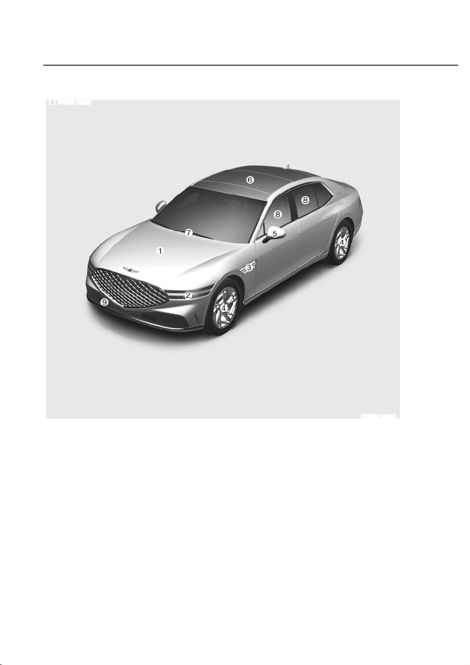
Front view
The actual shape may differ from the illustration.
ORS011001L
1. Hood ......................................................5-86
2. Headlight ..................................5-104, 9-64
3. Side repeater lamp .............................. 9-64
4. Tires and wheels ..................................9-34
5. Side view mirror ...................................5-71
6. Sunroof .................................................5-80
7. Front windshield wiper blades 5-118, 9-27
8. Windows ...............................................5-75
9. Front radar .............................................. 7-4
2-3
02
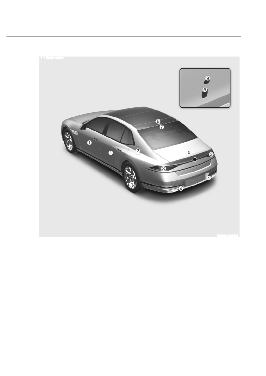
Rear view
The actual shape may differ from the illustration.
ORS012002N
(;7(5,2529(59,(:ʚ,,ʛ
1. Door ...................................................... 5-32
2. Fuel filler door ......................................5-96
3. Rear combination lamp .......................9-65
4. Reverse lamp .......................................9-65
5. Trunk .....................................................5-87
6. Trunk open/close button .....................5-89
7. High mounted stop lamp ....................9-65
8. Antenna ..............................................5-167
9. Wide-rear view camera .....................7-116
2-4
Vehicle Information, Consumer Information and Reporting Safety Defects
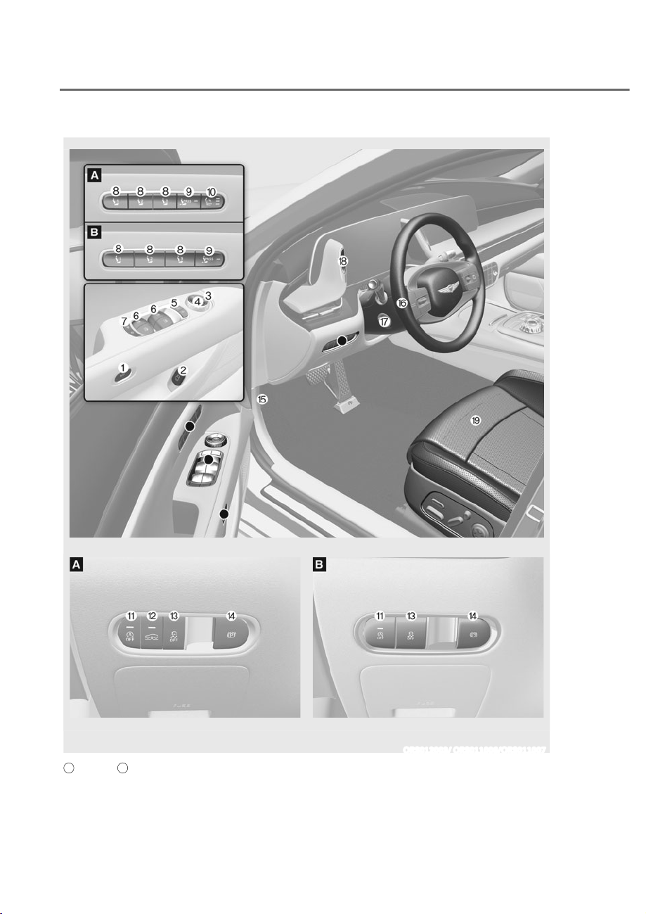
The actual shape may differ from the illustration.
ORS012003/ ORS011006/ORS011007
A
: Type A,
B
: Type B
INTERIOR OVERVIEW

2-5
02
1. Inside door open button ...................... 5-38
2. Inside door open lever .........................5-38
3. Side rear view mirror control
switch ....................................................5-72
4. Side rear view mirror folding
button ....................................................5-73
5. Central door lock switch ......................5-39
6. Power window switches ......................5-76
7. Rear window sunshade folding
button .................................................. 5-164
Electronic child safety lock button
...... 5-44
8. Integrated memory system .................5-50
9. Passenger seat adjustment switch......3-12
10. Seat massage switch ............................ 3-13
11. ISG (Idle Stop & Go) OFF button ..........6-51
12. Multi-chamber air suspension button ... 6-45
13. ESC (Electronic Stability Control) OFF
button ....................................................6-33
14. EPB (Electronic Parking Brake)
switch ....................................................6-24
15. Hood release lever ................................5-86
16. Steering wheel ...................................... 5-55
17. Steering wheel tilt/telescopic switch..5-56
18. Power trunk open/close button ..........5-89
19. Seat .......................................................... 3-3
2-6
Vehicle Information, Consumer Information and Reporting Safety Defects
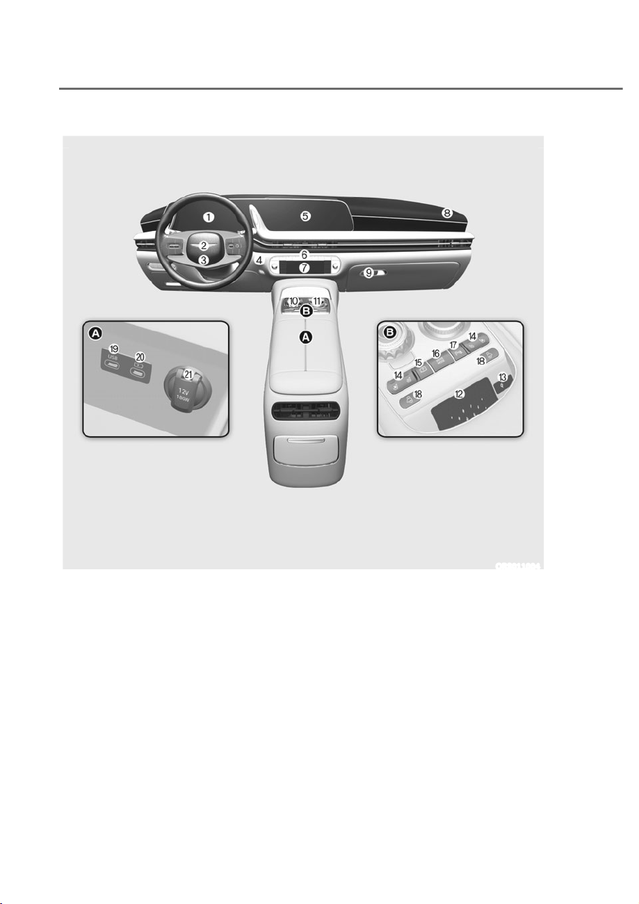
1. Instrument cluster .................................. 4-4
2. Horn .......................................................5-57
3. Driver’s front air bag .............................3-59
4. Engine Start/Stop button ....................... 6-5
5. Infotainment system ..........................5-168
6. Hazard warning flasher button .............. 8-2
7. Automatic climate control system ....5-121
8. Passenger’s front air bag .....................3-59
9. Glove box ............................................5-152
10. Rotary shifter (Rotary gear shift dial) .. 6-11
11. Infotainment system controller .........5-168
12. Wireless charging system pad ...........5-158
13. Wireless charging system indicator ..5-158
14. Seat Warmer/ ........................................3-33
Air ventilation seat ................................3-36
15. Parking/View button ..........................7-118
16. Drive mode button ............................... 6-61
17. Parking Safety button .........................7-134
18. Door close button ................................. 5-41
19. USB port ..............................................5-166
20. USB charger ........................................5-157
21. Power outlet ........................................5-156
The actual shape may differ from the illustration.
ORS011004
,167580(173$1(/29(59,(:ʚ,ʛ
2-7
02
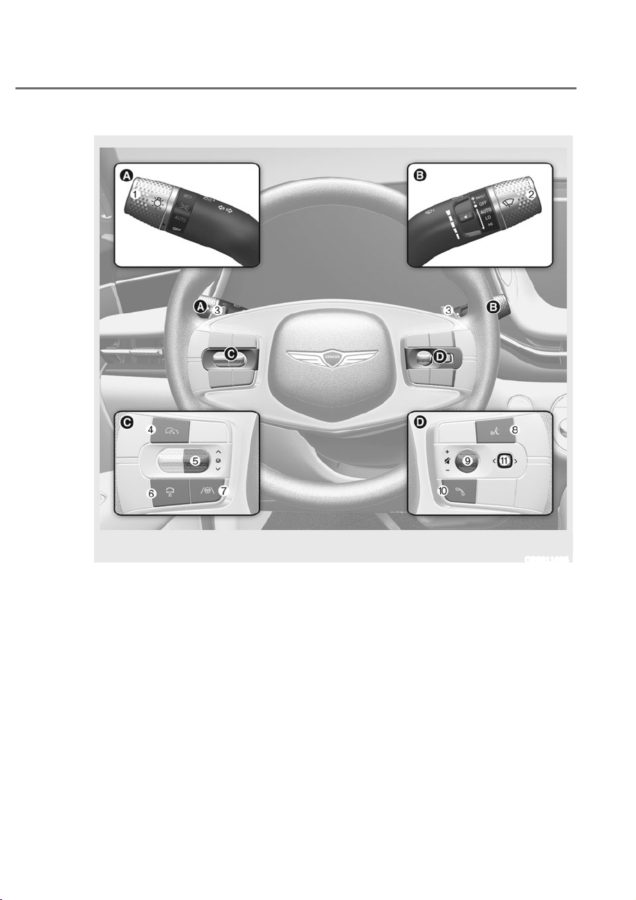
,167580(173$1(/29(59,(:ʚ,,ʛ
1. Lighting control lever .........................5-104
2. Wiper and washer control lever.........5-118
3. Paddle shifter ........................................ 6-21
4. Driving Assist button ............................ 7-58
5. LCD display control .............................. 4-26
6. Vehicle Distance button ....................... 7-79
7. Lane Driving Assist button .......7-30, 7-101
8. Voice recognition button ...................5-168
9. Steering wheel audio controls ...........5-167
10. Bluetooth wireless technology
hands-free button ..............................5-169
11. Optical mouse....................................... 4-26
The actual shape may differ from the illustration.
ORS011005
2-8
Vehicle Information, Consumer Information and Reporting Safety Defects
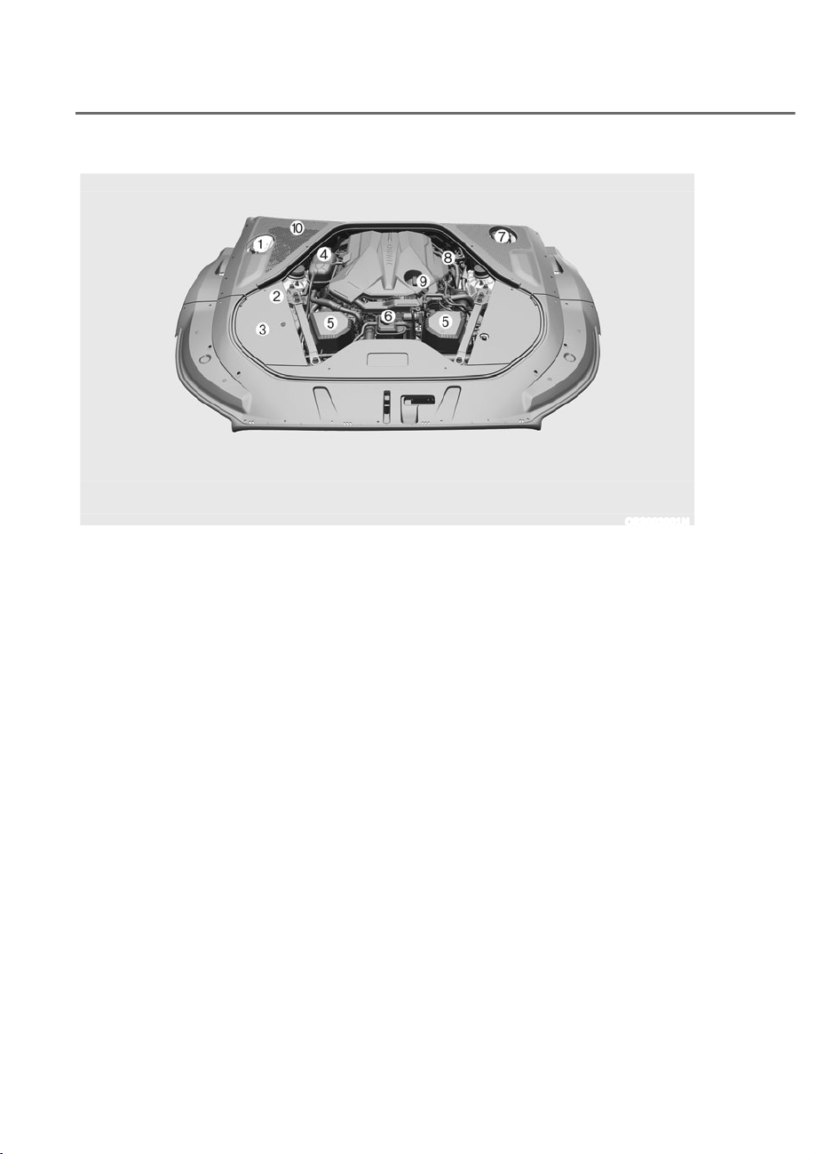
ENGINE COMPARTMENT
The actual engine compartment in the vehicle may differ from the illustration.
ORS092001N
1. Windshield washer fluid reservoir ....... 9-22
2. Jumper terminal ..................................... 8-5
3. Fuse box ................................................9-48
4. Engine coolant reservoir ...................... 9-18
5. Air cleaner .............................................9-23
6. Liquid-cooled intercooler coolant
reservoir ................................................9-18
7. Brake fluid reservoir ............................. 9-21
8. Engine oil dipstick ................................ 9-16
9. Engine oil filler cap ...............................9-16
10. Cabin air filter .......................................9-24

2-9
02
Items in. (mm)
Overall length 207.68 (5,275)
Overall width 75.98 (1,930)
Overall height 58.66 (1,490)
Tread
Tire size Front Rear
245/45 R20 65.16 (1,655) -
275/40 R20 - 65.35 (1,660)
245/40 R21 65.16 (1,655) -
275/35 R21 - 65.35 (1,660)
Wheelbase 125.2 (3,180)
ENGINE
Engine
Displacement
cu. in (cc)
Bore x Stroke
in. (mm)
Firing order No. of cylinders
3.5L T-GDI 211.8 (3,470)
3.6 x 3.4
(92 x 87)
1-2-3-4-5-6 6
3.5L T-GDI
48 V MHEV
211.8 (3,470)
3.6 x 3.4
(92 x 87)
1-2-3-4-5-6 6
DIMENSIONS

2-10
Vehicle Information, Consumer Information and Reporting Safety Defects
Light bulb Bulb type Wattage
Front
Headlight
Low LED LED
High LED LED
Turn signal lamp LED LED
Parking lamp LED LED
Daytime Running Lamp (DRL) LED LED
Side marker lamp LED LED
Puddle lamp LED LED
Side repeater lamp LED LED
Rear
Stop lamp LED LED
Tail lamp LED LED
Turn signal lamp LED LED
Reverse lamp LED LED
Side marker lamp LED LED
License plate lamp LED LED
High mounted stop lamp LED LED
Interior
Map lamp LED LED
Room lamp (without sunroof) LED LED
Personal lamp (with sunroof) LED LED
Vanity mirror lamp LED LED
Glove box lamp LED LED
Mood lamp/Foot lamp/Door foot lamp LED LED
Trunk lamp LED LED
BULB WATTAGE

2-11
02
Items Tire size
Wheel
size
Inflation pressure psi (kPa) Wheel bolt
torque
[lbf.ft (kgf.m,
N.m)]
Normal load Maximum load
Front Rear Front Rear
Full size tire
245/45R20 8.5J X 20
33
(230)
-
33
(230)
-
101~116
(14~16, 137~157)
275/40R20 9.5J X 20
-
35
(240)
-
35
(240)
245/40R21
8.5J X 21
38
(260)
38
(260)
275/35R21
9.5J X 21
39
(270)
39
(270)
Compact
spare tire *
1
T155/70R19 4.0T X 19
60 (420) 60 (420) 60 (420) 60 (420)
*1 :
If your vehicle is not equipped with a compact spare tire, a Tire Mobility Kit will be
provided with your vehicle.
NOTICE
ȉ It is permissible to add 3 psi to the standard tire pressure specification if colder
temperatures are expected soon.
ȉ Tires typically lose 1 psi (7 kPa) for every 12°F temperature drop. If extreme
temperature variations are expected, recheck your tire pressure as necessary to
keep them properly inflated.
ȉ Tire inflation pressures will vary with changes in elevation. If driving in areas of
higher or lower elevation, be sure to check and adjust for proper tire inflation.
CAUTION
ȉ When replacing tires, use the same size originally supplied with the vehicle.
ȉ Using tires of a different size can damage the related parts or not work properly.
ȉ When replacing tires, ALWAYS use the same size, type, construction and tread
pattern supplied with the vehicle for all tires.
TIRES AND WHEELS

2-12
Vehicle Information, Consumer Information and Reporting Safety Defects
Item Weight of volume Classification
Refrigerant
oz. (g)
24.69±0.88 (700±25) R-1234yf
Compressor lubricant
cu. in (cc)
3.52±0.35 (100±10) PAG
Contact an authorized retailer of Genesis Branded products for more details.
VEHICLE WEIGHT AND LUGGAGE VOLUME
Item
3.5L T-GDI 3.5L T-GDI 48 V MHEV
AWD AWD
Gross vehicle weight 6,085 lbs. (2,760 kg) 6,195 lbs. (2,810 kg)
Luggage volume
Items 3.5L T-GDI 3.5L T-GDI 48 V MHEV
SAE
ȸȹɁȻFXIWȺȻȸȐ ȸɁȼɀFXIWȺɁɁȐ
* MHEV: Mild Hybrid Vehicle
AIR CONDITIONING SYSTEM

2-13
02
To help achieve proper engine and powertrain performance and durability, use only
lubricants of the proper quality. The correct lubricants also help promote engine
efficiency that results in improved fuel economy.
These lubricants and fluids are recommended for use in your vehicle.
Lubricant Volume Classification
Engine oil
*1
Recommends
ȾȻ86TWȾɁȐ
SAE 0W-30, API SN PLUS/SP or
ILSAC GF-6
*4
Automatic transmission fluid ɀȾ86TWɀȹȐ
GS ATF SP-IV-RR, Genesis/
HYUNDAI genuine ATF SP-IV-
RR or other brands meeting the
above specification approved by
Genesis Customer Care
Engine coolant
3.5L T-GDI
ȸɁȻ86TWɀȿȻȻȐ
Mixture of antifreeze and water
(Phosphate-based Ethylene
glycol coolant for aluminum
radiator)
3.5L T-GDI 48 V
MHEV
ȸȸȼȿ86TWȸɁɀȽȐ
Liquid-cooled
intercooler
coolant
3.5L T-GDI
ȻȸȾ86TWȺɀȼȐ
3.5L T-GDI 48 V
MHEV
ȻɁȺ86TWȺȿȸȐ
Brake fluid
*2
As required DOT-4
Front differential oil (AWD)
*3
0.71±0.026 US qt.
ɁȽȾsɁɁȹȼȐ
HYPOID GEAR OIL API GL-5 SAE
75W/85
(SK HK SYN GEAR OIL
75W85 FM PLUS or equivalent)
Rear differential oil
*3
1.27±0.05 US qt.
ȸȹsɁɁȼȐ
HYPOID GEAR OIL API GL-5 SAE
75W/85 (SK HK SYN GEAR OIL
75W85 FM PLUS or equivalent)
Transfer case
oil (AWD)
Gear/Clutch
0.44±0.22 US qt.
ɁȻȹsɁɁȹȸȐ
SHELL TF0870B
Actuator
0.29±0.11 US qt.
ɁȹȾsɁɁȸɁȐ
Fuel ȸɀȺ86JDOȾȺȐ
Refer to “Fuel requirements”
section in chapter 1.
*1 :
Refer to the recommended SAE viscosity numbers on the next page.
*2 :
To maintain the best braking performance and ABS/ESC performance, we recommend
that you use fluid that conform to specifications.
*3 :
If the front/rear differential is submerged, visit an authorized retailer of Genesis Branded
products to replace the differential oil.
*4 :
Requires <API SN PLUS (or above) Full synthetic> grade engine oil. If a lower grade
engine oil (mineral oil including Semi-synthetic) is used, then the engine oil and engine
oil filter must be replaced as indicated severe maintenance condition.
RECOMMENDED LUBRICANTS AND CAPACITIES
2-14
Vehicle Information, Consumer Information and Reporting Safety Defects
Recommended SAE Viscosity Number
NOTICE
ȉ Always be sure to clean the area around any filler cap, drain plug, or dipstick
before checking or draining any lubricant. This is especially important in dusty or
sandy areas and when the vehicle is used on unpaved roads. Cleaning the plug
and dipstick areas will prevent dirt and grit from entering the engine and other
mechanisms that could be damaged.
ȉ Never add any additives to the engine oil. Engine oil additives can change the
properties of engine oil and may cause serious engine failure.
Engine oil viscosity (thickness) has an effect on fuel economy and cold weather
operating (engine start and engine oil flowability). Lower viscosity engine oils can
provide better fuel economy and cold weather performance, however, higher viscosity
engine oils are required for satisfactory lubrication in hot weather. Using oils of any
viscosity other than those recommended could result in engine damage.
When choosing an oil, consider the range of temperature your vehicle will be operated
in before the next oil change. Proceed to select the recommended oil viscosity from
the chart.
Temperature Range for SAE Viscosity Numbers
Temperature
°C -30 -20 -10 0 10 20 30 40 50
(°F) -10 0 20 40 60 80 100 120
Engine Oil
0W-300W-30
An engine oil displaying this American Petroleum Institute(API)
Certification Mark conforms to the International Lubricant
Specification Advisory Committee (ILSAC). It is recommended
to only use engine oils that uphold this API Certification Mark.
2-15
02
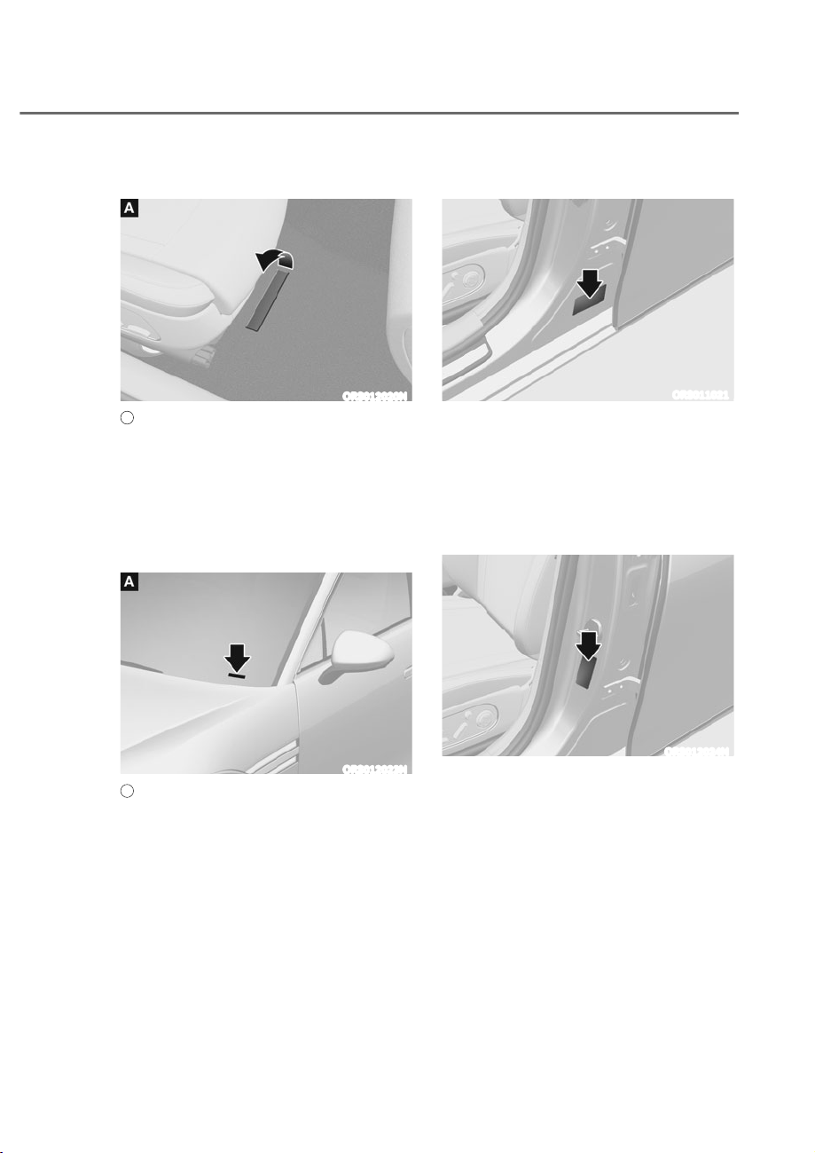
VEHICLE IDENTIFICATION
180%(5ʚ9,1ʛ
ORS012020N
A
: Frame number
The vehicle identification number (VIN)
is the number used in registering your
vehicle and in all legal matters pertaining
to its ownership, etc.
The number is punched on the floor
under the right front seat. To check the
number, open the cover.
ORS012023N
A
: VIN label (if equipped)
The VIN is also on a plate attached to
the top of the left side dashboard. The
number on the plate can easily be seen
through the windshield from outside.
VEHICLE CERTIFICATION
LABEL
ORS011021
The vehicle certification label attached
on the driver’s (or front passenger’s)
side center pillar gives the vehicle
identification number (VIN).
TIRE SPECIFICATION AND
PRESSURE LABEL
ORS012024N
The tires supplied on your new
vehicle are chosen to provide the best
performance for normal driving.
The tire label located on the driver’s
side center pillar gives the tire pressures
recommended for your vehicle.
2-16
Vehicle Information, Consumer Information and Reporting Safety Defects
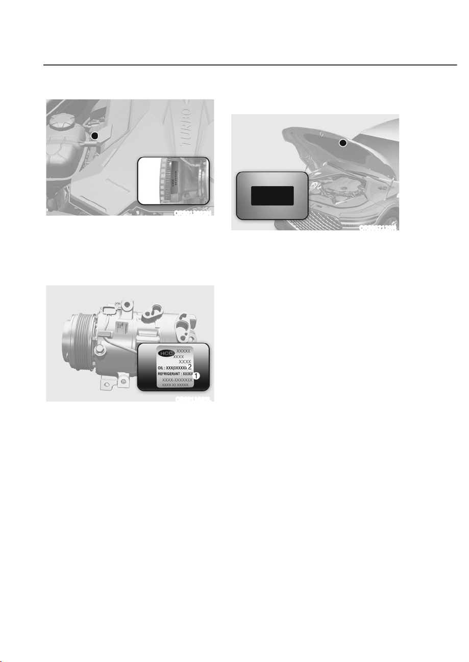
ENGINE NUMBER
ORS012022N
The engine number is stamped on the
engine block as shown in the drawing.
AIR CONDITIONER
COMPRESSOR LABEL
ORS011025L
A compressor label informs you the type
of compressor your vehicle is equipped
with such as model, supplier part
number, production number, refrigerant
M and refrigerant oil N.
REFRIGERANT LABEL
ʚ,)(48,33('ʛ
ORS052129N
The refrigerant label provides
information such as refrigerant type and
amount. (R-1234yf)

2-17
02
OPEN SOURCE SOFTWARE NOTICE
This vehicle contains software with open source licenses.
Open source software information including the source code, copyright notices and
referred license terms may be obtained on the website
https://www.genesis.com/worldwide/en/opensource.html
Hyundai Motor Company will provide the open source code to you in storage medium
such as CD-ROM for minimum charge covering the cost of performing source
distribution upon email request to ([email protected]) within a period of 3
years from the date of product purchase.
CONSUMER INFORMATION
This consumer information has been prepared in accordance with regulations
issued by the National Highway Traffic Safety Administration of the U.S. Department
of Transportation. Your retailer of Genesis Branded products will help answer any
questions you may have as you read this information.
Genesis Branded Vehicles are designed and manufactured to meet or exceed all
applicable safety standards.
For your safety, however, we strongly urge you to read and follow all directions in
this Owner’s Manual, particularly the information under the headings “NOTICE”,
“CAUTION” and “WARNING”.

2-18
Vehicle Information, Consumer Information and Reporting Safety Defects
If you believe that your vehicle has a defect which could cause a crash or
could cause injury or death, you should immediately inform the National
Highway Traffic Safety Administration (NHTSA) in addition to notifying Genesis
Customer Care.
If NHTSA receives similar complaints, it may open an investigation, and if it
finds that a safety defect exists in a group of vehicles, it may order a recall and
remedy campaign. However, NHTSA cannot become involved in individual
problems between you, your dealer, or Genesis Customer Care.
To contact NHTSA, you may call the Vehicle Safety Hotline toll-free at 1-888-
327-4236 (TTY: 1-800-424-9153);
go to http://www.safercar.gov;
download the SaferCar mobile application;
or write to: Administrator, NHTSA.
1200 New Jersey Ave, SE.,
Washington, DC. 20590.
You can also obtain other information about motor vehicle safety from
http://www.safercar.gov.
REPORTING SAFETY DEFECTS

3
3. Safety System
Important Safety Precautions .......................................................................... 3-2
Always Wear Your Seat Belt .........................................................................................3-2
Restrain All Children
.....................................................................................................3-2
Air Bag Hazards
............................................................................................................3-2
Driver Distraction
.........................................................................................................3-2
Control Your Speed
......................................................................................................3-2
Keep Your Vehicle In Safe Condition
...........................................................................3-2
Seats .................................................................................................................. 3-3
Safety Precautions .......................................................................................................3-6
Front Seats
....................................................................................................................3-7
Rear Seats
.................................................................................................................. 3-14
Head Restraint
........................................................................................................... 3-24
Pre-active Safety Seat (PSS)
.................................................................................... 3-31
Seat Warmers
............................................................................................................ 3-32
Air Ventilation Seats
.................................................................................................. 3-35
Seat Belts .........................................................................................................3-39
Seat Belt Safety Precautions .................................................................................... 3-39
Seat Belt Warning Light
............................................................................................ 3-40
Seat Belt Restraint System
....................................................................................... 3-41
Seat Belt-Driver’s 3-point System with Emergency Locking Retractor
................ 3-41
Pre-Active Seat Belt (PSB)
....................................................................................... 3-45
Additional Seat Belt Safety Precautions
.................................................................. 3-46
Care of Seat Belts
...................................................................................................... 3-48
Child Restraint System (CRS) .........................................................................3-49
Our Recommendation: Children Always In the Rear .............................................. 3-49
Selecting a Child Restraint System (CRS)
................................................................ 3-50
Installing a Child Restraint System (CRS)
................................................................ 3-51
Air Bag - Supplemental Restraint System .....................................................3-57
Where are the Air Bags? ............................................................................................ 3-59
How Does the Air Bags System Operate?
................................................................ 3-63
What to Expect After an Air Bag Inflates
................................................................. 3-66
Occupant Classification System (OCS)
.................................................................... 3-67
Why Didn’t My Air Bag Go Off In a Collision?
.......................................................... 3-73
SRS Care
.................................................................................................................... 3-78
Additional Safety Precautions
.................................................................................. 3-79
Air Bag Warning Labels
............................................................................................. 3-79

3-2
Safety System
You will find many safety precautions
and recommendations throughout this
section, and throughout this manual.
The safety precautions in this section are
among the most important.
Always Wear Your Seat Belt
A seat belt is your best protection in all
types of accidents. Air bags are designed
to supplement seat belts, not replace
them. So even though your vehicle is
equipped with air bags, ALWAYS make
sure you and your passengers wear your
seat belts, and wear them properly.
Restrain All Children
All children under age 13 should ride
in your vehicle properly restrained in a
rear seat, not the front seat. Infants and
small children should be restrained in
an appropriate Child Restraint System.
Larger children should use a booster
seat with the lap/shoulder belt until they
can use the seat belt properly without a
booster seat.
Air Bag Hazards
While air bags can save lives, they can
also cause serious or fatal injuries to
occupants who sit too close to them, or
who are not properly restrained. Infants,
young children, and short adults are at
the greatest risk of being injured by an
inflating air bag. Follow all instructions
and warnings in this manual.
Driver Distraction
Driver distraction presents a serious and
potentially deadly danger, especially for
inexperienced drivers. Safety should be
the first concern when behind the wheel
and drivers need to be aware of the wide
array of potential distractions, such as
drowsiness, reaching for objects, eating,
personal grooming, other passengers,
and using mobile phones.
Drivers can become distracted when
they take their eyes and attention off
the road or their hands off the wheel to
focus on activities other than driving.
To reduce your risk of distraction and an
accident:
• ALWAYS set up your mobile devices
(for example, MP3 players, phones,
navigation units, etc.) when your
vehicle is parked or safely stopped.
• ONLY use your mobile device when
allowed by laws and conditions permit
safe use. NEVER text or email while
driving. Most countries have laws
prohibiting drivers from texting. Some
countries and cities also prohibit
drivers from using handheld phones.
• NEVER let the use of a mobile device
distract you from driving. You have a
responsibility to your passengers and
others on the road to always drive
safely, with your hands on the wheel
as well as your eyes and attention on
the road.
Control Your Speed
Excessive speed is a major factor in crash
injuries and deaths. Generally, the higher
the speed, the greater the risk, but
serious injuries can also occur at lower
speeds. Never drive faster than is safe
for current conditions, regardless of the
maximum speed posted.
Keep Your Vehicle In Safe
Condition
Having a tire blowout or a mechanical
failure can be extremely hazardous. To
reduce the possibility of such problems,
check your tire pressures and condition
frequently, and perform all regularly
scheduled maintenance.
IMPORTANT SAFETY PRECAUTIONS
3-3
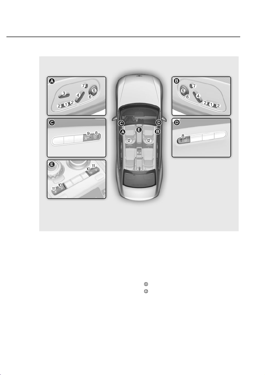
03
M Seat sliding forward or rearward
N Seat cushion tilt/Seat height
O Seat cushion extension
P Seatback angle
Q Lumbar support
R Seatback bolster
S Head restraint adjustment
T Massage switch
U Walk-in seat switch
V Air ventilation seat
Seat warmers
Head restraint
SEATS
The actual shape may differ from the illustration.
ORS031001
ORS031001
Front seat
3-4
Safety System
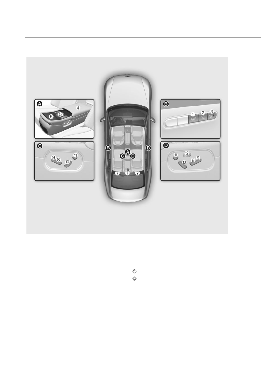
The actual shape may differ from the illustration.
ORS032002N
ORS032002N
Rear seat
M Rest mode switch (if equipped)
N Return mode switch (if equipped)
O Massage switch
P Armrest
Q Infotainment system controller
R Armrest touchscreen
S Head restraint
T Seat sliding forward or rearward
U Seat cushion tilt
V Seatback angle
Head restraint adjustment
Walk-in seat switch

3-5
03
ORS032097N
ORS032097N
Infotainment system
6HOHFWȁ6HWXSɌ9HKLFOHɌ6HDWȂIURPWKH6HWWLQJVPHQXLQWKHLQIRWDLQPHQWV\VWHP
screen, you may use various convenience functions.
• Seat position change alert: Detailed information of the seat switch and image is
displayed when the seat position moves.
• Heated/Ventilated features
- Auto. Controls That Use Climate Control Settings (for driver’s seat): The seat
temperature is automatically controlled.
- Seat heater balance: When the seat heater is on, you may lower the seat heater
(warmer) setting, or may turn the seat heater off for either the seatback or seat
cushion.
• Seating easy access
- Steering wheel easy access: Moves the steering wheel when the driver enters or
leaves the vehicle.
- Driver seat easy access: The distance (Normal/Extended/Off) the seat automatically
moves when the driver enters or leaves the vehicle may be selected.
- Passenger seat easy access: Moves the passenger seat when the passenger
enters or leaves the vehicle.
- Rear Left Seat Easy Access: Moves the rear left seat when the passenger exits the
vehicle.
- Rear Right Seat Easy Access: Moves the rear right seat when the passenger exits
the vehicle.
• Ergo-motion seat
- Posture assist: The seat is adjusted to assist the driver’s posture after driving for
an hour.
- Smart support: The driver's seat bolster is increased when SPORT mode is
selected or when driving at high speed.
See additional information in supplied Infotainment Manual.
Information
The information provided may differ depending on which functions are applicable to your
vehicle.

3-6
Safety System
Safety Precautions
Adjusting the seats so that you are sitting
in a safe, comfortable position plays an
important role in driver and passenger
safety, together with seat belts and air
bags, in an accident.
WARNING
Do not use a cushion that reduces
friction between the seat and the
passenger. The passenger’s hips may
slide under the lap portion of the seat
belt during an accident or a sudden
stop.
Serious or fatal internal injuries could
result because the seat belt cannot
operate properly.
Air bags
You can take steps to reduce the risk
of being injured by an inflating air bag.
Sitting too close to an air bag greatly
increases the risk of injury in the event
the air bag inflates.
The National Highway Traffic Safety
Administration (NHTSA) recommends
that drivers allow at least 10 inches (25
cm) between the center of the steering
wheel and their chest.
WARNING
To reduce the risk of serious injury or
death from an inflating air bag, take the
following precautions:
• Adjust the driver’s seat as far to the
rear as possible while maintaining
the ability to control the vehicle.
• Adjust the front passenger seat as far
to the rear as possible.
• Hold the steering wheel by the rim
with your hands at the 9 o’clock and
3 o’clock positions to minimize the
risk of injuries to your hands and
arms.
• NEVER place anything or anyone
between you and the air bag.
• Do not allow the front passenger to
place feet or legs on the dashboard
to minimize the risk of leg injuries.
Seat belts
Always fasten your seat belt before
starting any trip. At all times, passengers
should sit upright and be properly
restrained. Infants and small children
must be restrained in appropriate Child
Restraint Systems. Children who have
outgrown a booster seat and adults must
be restrained using the seat belts.

3-7
03
WARNING
Take the following precautions when
adjusting your seat belt:
• NEVER use one seat belt for more
than one occupant.
• Always position the seatback upright
with the lap portion of the seat belt
snug and low across the hips.
• NEVER allow children or small infants
to ride on a passenger’s lap.
• Do not route the seat belt across your
neck, across sharp edges, or reroute
the shoulder strap away from your
body.
• Do not allow the seat belt to become
caught or jammed.
Front Seats
The front seat can be adjusted by using
the control switches located on the
outside of the seat cushion. Before
driving, adjust the seat to the proper
position so that you can easily control
the steering wheel, foot pedals and
controls on the instrument panel.
WARNING
Take the following precautions when
adjusting your seat:
• NEVER attempt to adjust the seat
while the vehicle is moving. The seat
could respond with unexpected
movement and may cause loss
of vehicle control resulting in an
accident.
• Do not place anything under the
front seats. Loose objects in the
driver’s foot area could interfere
with the operation of the foot pedals,
causing an accident.
• Do not allow anything to interfere
with the normal position and proper
locking of the seatback.
• Do not place a cigarette lighter on
the floor or seat. When you operate
the seat, gas may exit out of the
lighter causing a fire.
• Use extreme caution when picking
up small objects trapped under the
seats or between the seat and the
center console. Your hands might be
cut or injured by the sharp edges of
the seat mechanism.
• If there are occupants in the rear
seats, be careful while adjusting the
front seat position.
• Make sure that the seat is locked in
place after the adjustment. If not,
the seat might move unexpectedly
resulting in an accident.
3-8
Safety System
CAUTION
To prevent injury:
• Do not adjust your seat while
wearing your seat belt. Moving the
seat cushion forward may cause
strong pressure on your abdomen.
• Do not allow your hands or fingers to
get caught in the seat mechanisms
while the seat is moving.
WARNING
NEVER allow children in the vehicle
unattended. The power seats are
operable when the vehicle is turned off.
NOTICE
To prevent damage to the seats:
• Always stop adjusting the seats when
the seat has been adjusted as far
forward or rearward as possible.
• Do not adjust the seats longer than
necessary when the vehicle is turned
off. This may result in unnecessary
battery drain.
• Do not operate two or more seats at
the same time. This may result in an
electrical malfunction.
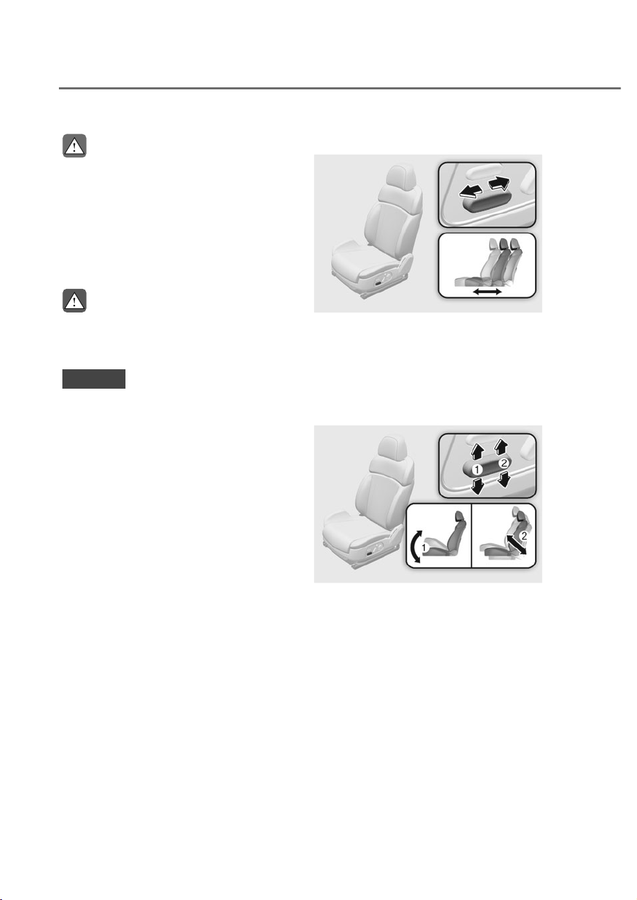
Forward and rearward adjustment
ORS031004
ORS031004
To move the seat forward or rearward:
1. Push the control switch forward or
rearward.
2. Release the switch once the seat
reaches the desired position.
Seat cushion tilt/height adjustment
ORS031007
ORS031007
Seat cushion tilt M
To change the angle of the front part of
the seat cushion:
Push the front portion of the control
switch up to raise or down to lower the
front part of the seat cushion.
Release the switch once the seat reaches
the desired position.
3-9
03
Seat height N
To change the height of the seat:
Push the rear portion of the control
switch up to raise or down to lower the
height of the seat cushion.
Release the switch once the seat reaches
the desired position.
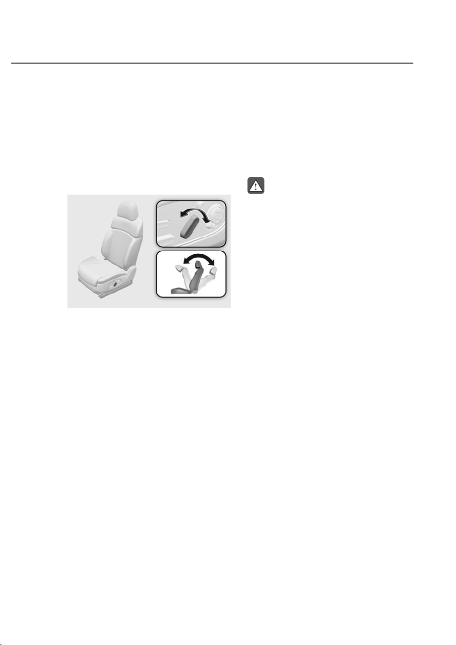
Seatback angle adjustment
ORS031006
ORS031006
To recline the seatback:
1. Push the control switch forward or
rearward.
2. Release the switch once the seatback
reaches the desired position.
Reclining seatback
Sitting in a reclined position when the
vehicle is in motion can be dangerous.
Even when buckled up, the protections
of your restraint system (seat belts and
air bags) is greatly reduced by reclining
your seatback.
WARNING
NEVER ride with a reclined seatback
when the vehicle is moving.
Riding with a reclined seatback
increases your chance of serious or fatal
injuries in the event of a collision or
sudden stop.
Driver and passengers should ALWAYS
sit well back in their seats, properly
belted, and with the seatbacks upright.
Seat belts must be snug against your
hips and chest to work properly. When
the seatback is reclined, the shoulder
belt cannot do its job because it will not
be snug against your chest. Instead,
it will be in front of you. During an
accident, you could be thrown into the
seat belt, causing neck or other injuries.
The more the seatback is reclined,
the greater chance the passenger’s
hips will slide under the lap belt or the
passenger’s neck will strike the shoulder
belt.
3-10
Safety System
Seat cushion extension adjustment
(for driver's seat) (if equipped)
ORS031005
ORS031005
To move the front part of the cushion
forward or rearward:
1. Push the control switch forward or
rearward.
2. Release the switch once the seat
cushion reaches the desired length.
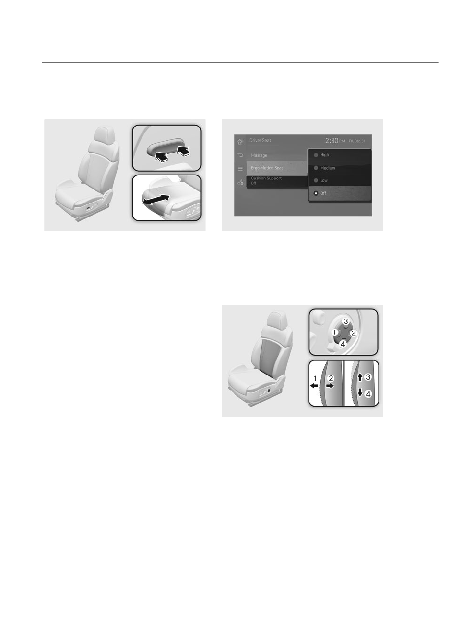
Seat cushion support adjustment
(for driver's seat) (if equipped)
ORS031100L
ORS031100L
6HOHFWȁ6HWXSɌ6HDWɌ'ULYHU6HDWɌ
Cushion Support’ from the infotainment
system. The driver’s seat cushion support
can be adjusted to high, normal, and low,
or turned off.
Lumbar support (if equipped)
ORS031008
ORS031008
To adjust the lumbar support:
1. Press the front portion of the switch M
to increase support or the rear portion
of the switch N to decrease support.
2. Press switch O or P to move the
support position up or down.
3. Release the switch once the lumbar
support reaches the desired position.
3-11
03
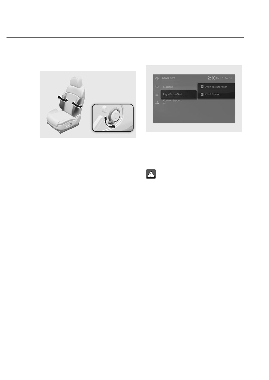
Seat bolster adjustment (if
equipped)
ORS031009
ORS031009
To adjust seat bolster:
1. Push the adjustment lever clockwise,
the seatback bolster will be
adjusted inward. Push the switch
counterclockwise, the seatback
bolster will be adjusted outward.
2. Release the lever once the bolster
reaches the desired position.
Ergo-motion seat (if equipped)
ORS031098L
ORS031098L
6HOHFWȁ6HDWɌ'ULYHU6HDWɌ(UJR0RWLRQ
6HDWȂRUȁ6HWXSɌ9HKLFOHɌ6HDWɌ(UJR
Motion Seat’ from the infotainment
system's Settings menu to select and set
up supplemental functions.
WARNING
Before actually using each function, try
the functions with the vehicle parked.

3-12
Safety System
Smart Posture Assist
After driving for an hour, Posture Assist
automatically adjusts the pelvis and back
portion of the seat to assist the posture.
You can activate or deactivate Posture
Assist function from the Settings menu in
the infotainment system screen. Select:
- 6HDWɌ'ULYHU6HDWɌ(UJR0RWLRQ6HDW
Ɍ6PDUW3RVWXUH$VVLVW
- 6HWXSɌ9HKLFOHɌ(UJR0RWLRQ6HDWɌ
Smart Posture Assist
Smart support
When the sport mode is selected during
drive mode, the seat bolster rises and
cushion support is lowered. Driving in
modes other than sport mode, the seat
bolster will raise when the vehicle speed
is above 80 mph (130 km/h).
The seat bolster will return to its original
position.
To activate the Posture Assist function
from the Settings menu in the
infotainment system screen. Select:
- 6HDWɌ'ULYHU6HDWɌ(UJR0RWLRQ6HDW
Ɍ6PDUW6XSSRUW
- 6HWXSɌ9HKLFOHɌ(UJR0RWLRQ6HDWɌ
Smart Support
Adjusting the front passenger seat
from the Driver’s Seat
ORS031010
ORS031010
ORS031011
ORS031011
Seating position, seatback angle and
cushion angle/height of the front
passenger seat can be adjusted by
operating the switches from the driver’s
seat.
1. Press the passenger seat control
button on the door of the driver’s seat.
• Indicator light on the button
illuminates.
2. Operate the switch on the driver’s seat
to adjust the front passenger seat.
• For more information refer to the
“Front Seats” section in this chapter.
• Press the button again to turn off
the function.
• If you do not adjust the front
passenger seat within 15 seconds
after pressing the passenger seat
adjustment button, the front
passenger seat adjustment function
automatically turns off.
3-13
03
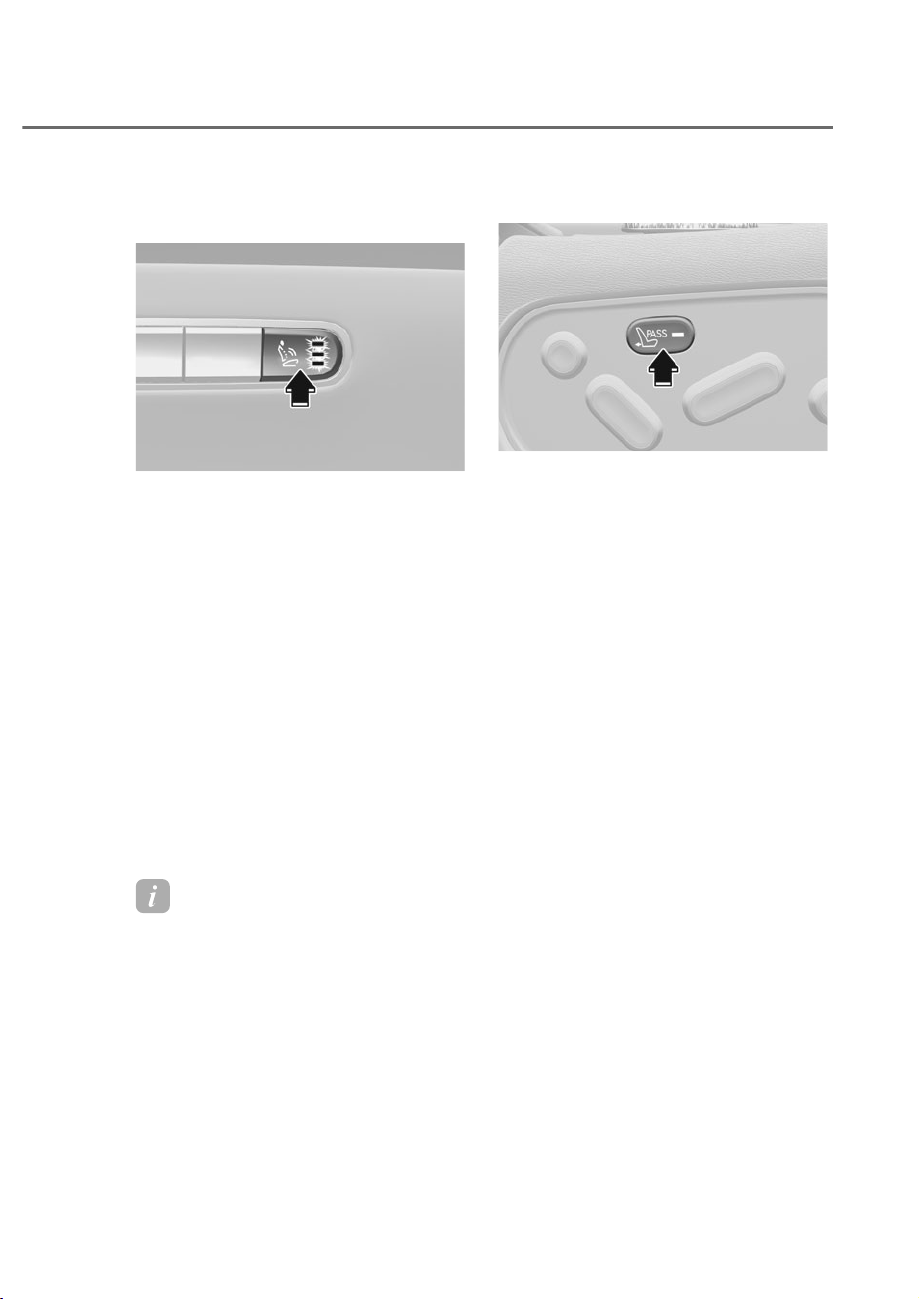
Seat massage function (for driver’s
seat) (if equipped)
ORS031016
ORS031016
Use the massage function to relax after
a long drive, or when resting inside the
vehicle.
1. While the Engine Start/Stop button is
in ‘ON’ position, press the massage
button on the driver’s seat door to
start the function.
• The light indicating massage
intensity level illuminates.
2. Press the button again to set the
intensity level.
• Each time you press the button, the
intensity setting of the Massage it is
changed as follows:
+LJKɌ0HGLXPɌ/RZɌ2II
• To stop the function, press the
button multiple times until the
indicator light does not illuminate.
Information
To set the massage function or change
WKHPRGHVHOHFWµ6HDWĺ'ULYHU6HDWĺ
0DVVDJH¶RUµ6HWXSĺ9HKLFOHĺ6HDW
ĺ0DVVDJH¶IURPWKHLQIRWDLQPHQWPHQX
screen.
Walk-in switch (if equipped)
ORS031104
ORS031104
For the comfort of rear seat passengers,
seating position, seatback angle and
cushion angle of the front passenger seat
can be adjusted by operating the rear
seat control switches.
1. Press the walk-in device switch on the
right side of the rear seat.
• Indicator light on the walk-in device
switch illuminates.
2. Operate the rear seat control switch to
adjust the front passenger seat.
• For more information refer to the
“Front Seats” section in this chapter.
• Press the switch again to turn off
the walk-in device.
• Adjust the front passenger seat
within 15 seconds after pressing the
walk-in device switch. Otherwise
the front passenger seat adjustment
function automatically turns off.
3-14
Safety System
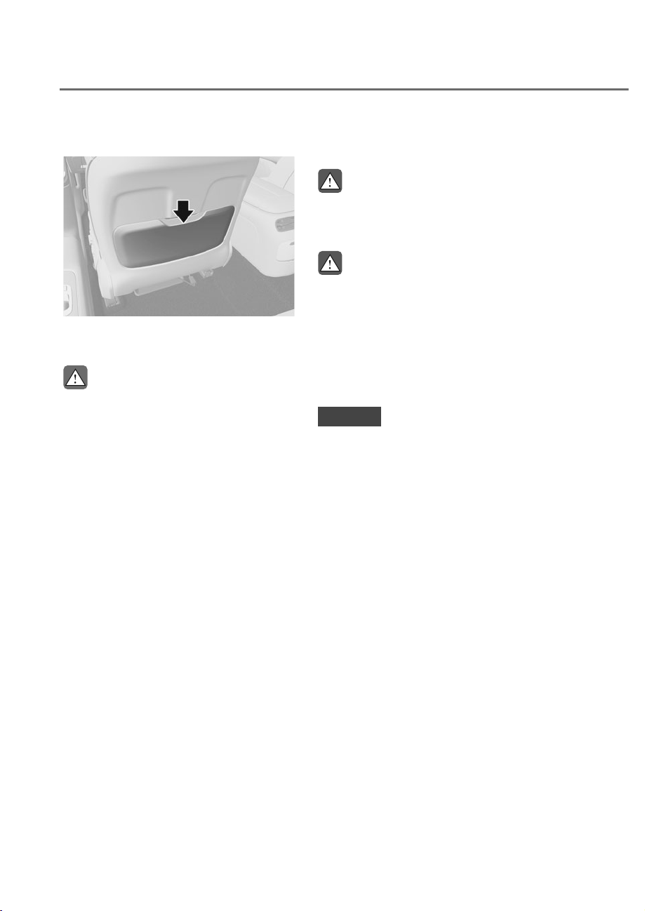
Seatback pocket
ORS031015
ORS031015
The seatback pocket is provided on the
back of the front seatbacks.
CAUTION
Do not put heavy or sharp objects in the
seatback pockets. In an accident they
could come loose from the pocket and
injure occupants.
Rear Seats
WARNING
NEVER adjust the rear power seats
when a Child Restraint System is
installed in that seat.
WARNING
To prevent injury:
• Do not adjust your seat while
wearing your seat belt. Moving the
seat cushion forward may cause
strong pressure on your abdomen.
• Do not allow your hands or fingers to
get caught in the seat mechanisms
while the seat is moving.
NOTICE
To prevent damage to the seats:
• Always stop adjusting the seats when
the seat has been adjusted as far
forward or rearward as possible.
• Do not adjust the seats longer than
necessary when the engine is turned
off. This may result in unnecessary
drain of the battery.
• Do not operate two or more seats at
the same time. This may result in an
electrical malfunction.
3-15
03
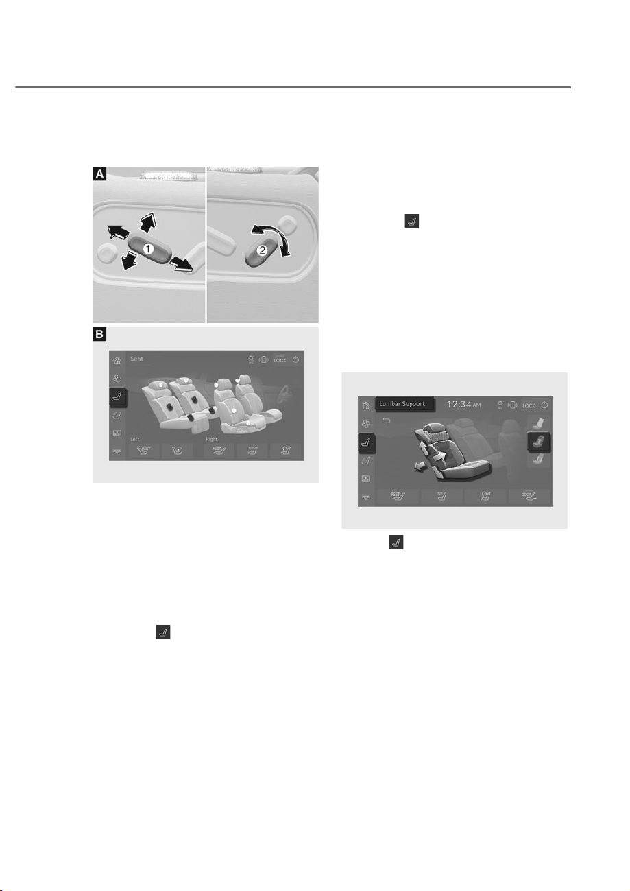
Seat sliding, seatback angle and seat
cushion tilt adjustment (if equipped)
ORS031094
ORS031094
ORS032150N
ORS032150N
Adjusting seat position and vertical height
• Control switch (Type A)
- Seat position adjustment: Slide the
switch M forward or backward to
adjust seat position.
- Seat height adjustment: Push down
or pull up the switch M to adjust
seat height.
• Armrest touchscreen (Type B)
1. Press
on the left side of
the menu from the armrest
touchscreen.
- Seat adjustment screen is
displayed.
2. Touch the lower part adjustment
button and adjust the seat position
and cushion angle.
Seatback angle
• Control Switch (Type A)
Slide the switch N forward or
backward to adjust seatback angle.
• Armrest touchscreen (Type B)
1. Press
on the left side of
the menu from the armrest
touchscreen.
- Seat adjustment screen is
displayed.
2. Touch the center part adjustment
button and adjust the seatback
angle.
Lumbar support adjustment (if
equipped)
ORS032021N
ORS032021N
1. Press on the left side of the menu
from the armrest touchscreen.
• Seat adjustment screen is displayed.
2. Press the adjustment button on the
center of the rear seat to adjust, then
select lumbar support function from
the menu.
3. Touch the arrows to adjust the
position of the lumbar support.
3-16
Safety System
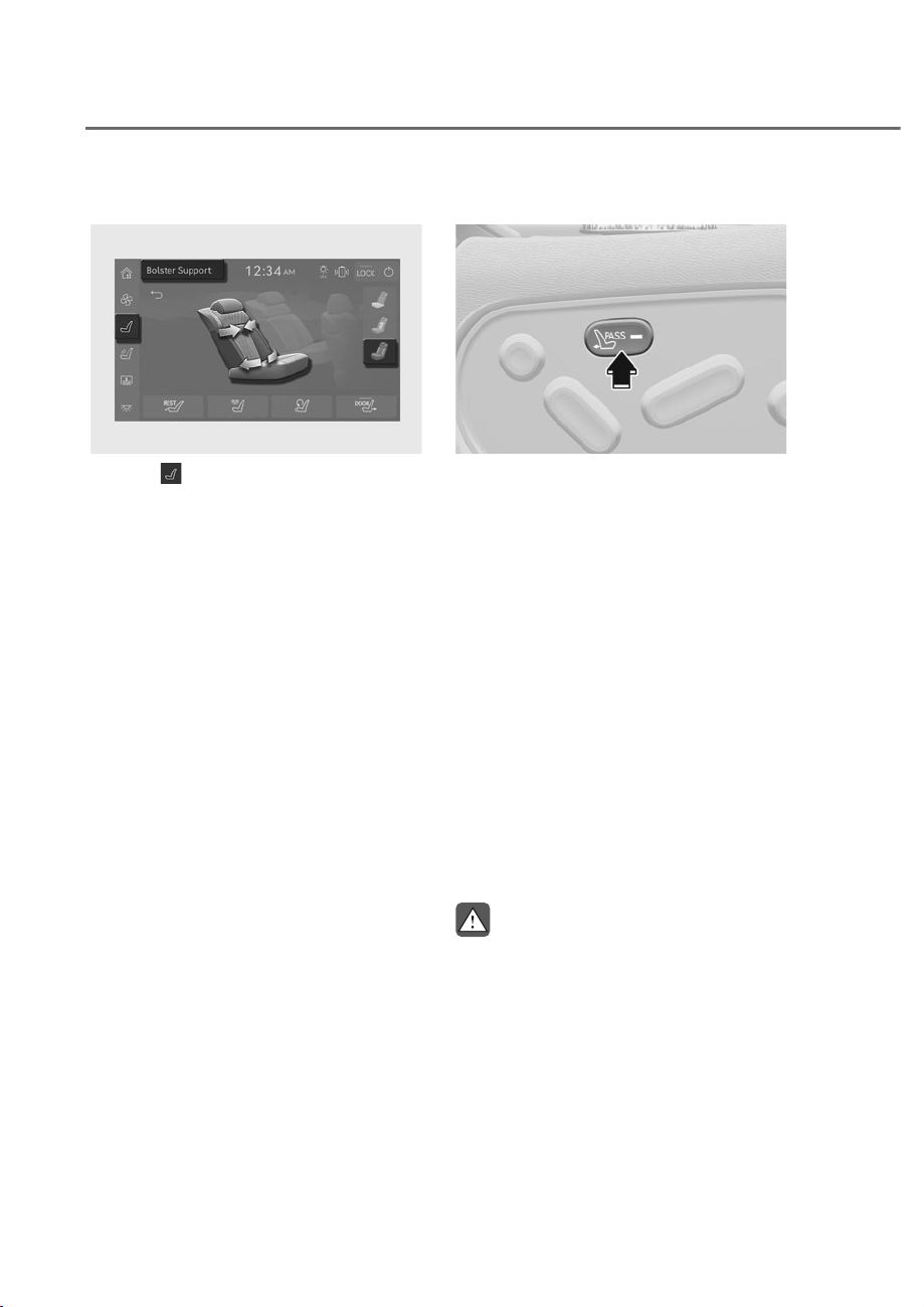
Adjusting seat bolster (if equipped)
ORS032022N
ORS032022N
1. Press on the left side of the menu
from the armrest touchscreen.
• Seat adjustment screen is displayed.
2. Press the adjustment button on the
center of the rear seat to adjust, then
select seat bolster function from the
menu.
3. Touch the arrows to adjust the
position of the seat bolster.
Walk-in switch (if equipped)
ORS031104
ORS031104
Seating position, seatback angle and
cushion angle of the front passenger seat
can be adjusted by operating the rear
seat control switches.
1. Press the walk-in device switch on the
center armrest of rear seat.
• Indicator light on the walk-in device
switch illuminates.
2. Operate the rear seat control switch to
adjust the front passenger seat.
• For more information refer to the
“Front Seats” section in this chapter.
• Press the switch again to turn off
the walk-in device.
• If you do not adjust the front
passenger seat within 15 seconds
after pressing the walk-in
switch, the front passenger seat
adjustment function automatically
turns off.
WARNING
Do not adjust the passenger seat when
a passenger is seated.
3-17
03
Easy access switch (for passenger’s
Seat) (if equipped)
ORS032109N
ORS032109N
ORS032023N
ORS032023N
9HKLFOHVHTXLSSHGZLWK,QWHJUDWHG
Memory System
The seats can automatically move
backward by opening the rear door with
the rear seats moved forward.
1. Press
on the left side of the menu
from the armrest touchscreen.
• Seat adjustment screen is displayed.
2. Touch either the right, or left seat
adjustment button M on the rear seat.
3. Press the DOOR button.
• The indicator light on the button
illuminates and easy access
function for entrance/exit is
enabled.
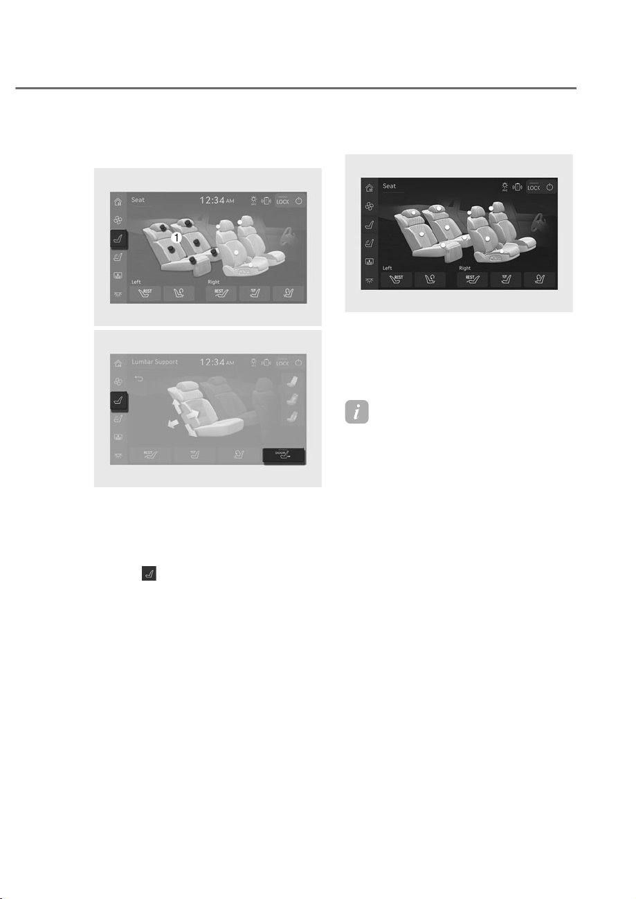
VIP seat (if equipped)
ORS032024N
ORS032024N
The rear seat occupant can adjust the
VIP seat and front passenger seats for
VIP convenience. The front and rear
passenger seats are also adjustable
through the armrest touchscreen.
Information
• Convenience features of the rear left
seat is not available under the following
circumstances when:
- The driver’s seat is positioned back
too far.
- The driver’s seatback is reclined
back too much.
• Operating range of the convenience
features of the rear left seat may
vary depending on the position of the
driver’s seat.
3-18
Safety System
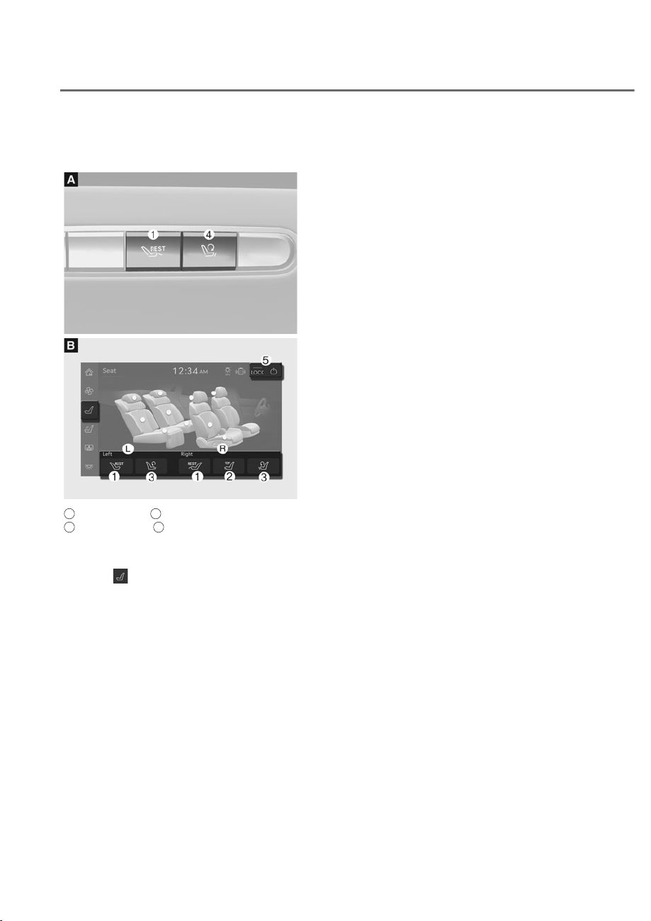
VIP seat mode switches (if
equipped)
ORS031025
ORS031025
ORS032154N
ORS032154N
A
: Control switch,
B
: Armrest touchscreen,
L
: Rear seat (Left),
R
: Rear seat (Right)
You can automatically adjust the seat for
comfort or various in-vehicle activities.
1. Press
on the left side of the menu
from the armrest touchscreen.
• Seat adjustment screen is displayed.
2. Press and hold the appropriate mode
for your activity.
• Relax (REST) mode, Reading mode,
Return mode.
Relax (REST) Mode
The front and rear passenger seats are
automatically adjusted for comfort. Press
and hold button M on the rear door or
on the armrest touchscreen. Each seat is
adjusted automatically as below.
• Rear left seat
- 6HDWEDFNWLOWVEDFNZDUGɌ+HDG
UHVWUDLQWPRYHVEDFNZDUGɌ+HDG
restraint moves downward
- 6HDWSRVLWLRQPRYHVIRUZDUGɌ)URQW
SDUWRIWKHFXVKLRQULVHVɌ/XPEDU
support protrudes.
• Rear right seat
- 6HDWEDFNWLOWVEDFNZDUGɌ+HDG
UHVWUDLQWPRYHVEDFNZDUGɌ+HDG
restraint moves downward
- 6HDWSRVLWLRQPRYHVIRUZDUGɌ)URQW
SDUWRIWKHFXVKLRQULVHVɌ/XPEDU
support protrudes.
- &DOIVXSSRUWXQIROGVɌ&DOIVXSSRUW
rises (if equipped)
• Front passenger seat
- Vertical seat position moves
GRZQZDUGɌ6HDWSRVLWLRQPRYHV
forward
- 6HDWEDFNWLOWVIRUZDUGɌ+HDG
restraint moves downward
- +HDGUHVWUDLQWPRYHVIRUZDUGɌ
Front part of the cushion lowers
• Once adjusted to Relax (REST) mode,
a sound rings to inform that the
adjustment is complete

3-19
03
NOTICE
• Do not press the Relax (REST) mode
switch again while operating the
seat positions for Relax (REST)
mode. It may abruptly stop the seat
movement.
• When you operate the seat control
switch while adjusting the seat
positions for the Relax (REST) mode,
it stops the automatic seat position
adjustment. In this case, manually
adjust the seat positions.
• Any items, which occupy the front
passenger's seat, may get damaged
while automatically adjusting the
seat positions for the Relax (REST)
mode. Do not put any items on the
front passenger's seat.
Information
• Relax (REST) mode switches for
adjusting the front passenger’s seat do
not operate in the following situations
when:
- The Engine Start/Stop button is in
the OFF position.
- A passenger occupies the front
passenger’s seat.
- An item occupies the front
passenger’s seat.
- The front passenger’s door is open.
- The front passenger’s seatbelt is
fastened.
• Relax (REST) mode for rear left seat
is unavailable under the following
circumstances when:
- The driver’s seat is positioned back
too far.
- The driver’s seatback is reclined
back too much.
• Operating range of the Relax (REST)
mode of the rear left seat may vary
depending on the position of the
driver’s seat.
Information
• The seat position changes to Relax
(REST) mode while the button M is
pressed. The seat stops moving when
the button M is released.
• The forward and rearward position for
the rear seats are adjusted based on its
current position. The starting position
may differ.
• Operating the seat control switch while
the seat is being adjusted for Relax
(REST) mode stops the seats from
moving.
To adjust the seats again, use the
control switch and adjust manually.

3-20
Safety System
Reading mode (Rear right seat)
The rear passenger seats are
automatically adjusted for reading.
Press and hold button N on the armrest
touchscreen. Each seat is adjusted as
below.
• Calf support is lowered and moved
backward. (if equipped)
• 6HDWSRVLWLRQPRYHVEDFNZDUGɌ)URQW
part of the cushion moves downward
• Seatback tilts forward
• Once the adjustment for reading
mode is complete, a sound rings and
the rear right room lamp automatically
turns on.
Information
• The seat position changes to Reading
mode while the button N is pressed.
The seat stops moving when the button
N is released.
• Operating the seat control switch while
the seat is being adjusted for Reading
mode stops the seats from moving.
To adjust the seats again, use the
control switch and adjust manually.
• Reading mode is only available while
the engine is turned on.
5HWXUQPRGHLIHTXLSSHG
Return all passenger seats to the regular
position suited for driving after using the
seat mode (rest mode, reading mode).
Press and hold button O on the rear door
or touch the button from the armrest
touchscreen. Each seat is adjusted
automatically as below.
• Rear left seat
- 6HDWSRVLWLRQPRYHVEDFNZDUGɌ
Front part of the cushion moves
GRZQZDUGɌ/XPEDUVXSSRUWPRYHV
backward
- +HDGUHVWUDLQWPRYHVGRZQZDUGɌ
Seatback tilts forward
• Rear right seat
- Calf support is lowered and moved
backward. (if equipped)
- 6HDWSRVLWLRQPRYHVEDFNZDUGɌ
)URQWSDUWRIWKHFXVKLRQORZHUVɌ
Lumbar support moves downward
- +HDGUHVWUDLQWORZHUVɌ6HDWEDFN
tilts forward
• Passenger seat
- Vertical seat position moves
GRZQZDUGɌ+HDGUHVWUDLQWPRYHV
GRZQZDUGɌ+HDGUHVWUDLQWPRYHV
backward
• 6HDWUHWXUQVWRVHWSRVLWLRQɌ6HDWEDFN
returns to set position
• Once adjusted to Return mode,
a sound rings to inform that the
adjustment is complete.
3-21
03
Information
Return function switch for adjusting the
front passenger's seat do not operate in
the following situations when:
• The Engine Start/Stop button is in the
OFF position.
• A passenger occupies the front
passenger's seat.
• An item occupies the front passenger's
seat.
• The front passenger's door is open.
• The front passenger's seatbelt is
fastened.
Information
• The seat position changes to Return
mode while the button O is pressed.
The seat stops moving when the button
O is released.
• Operating the seat control switch while
the seat is being adjusted for Return
mode stops the seats from moving.
To adjust the seats again, use the
control switch and adjust manually.
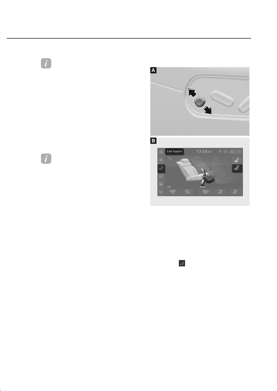
Calf support adjustment (if equipped)
ORS031027
ORS031027
ORS032155N
ORS032155N
Place your leg on the calf support and
adjust its angle to relax.
• Control switch (Type A)
Slide the calf support switch
diagonally upward or downward to
adjust the angle.
• Armrest touchscreen (Type B)
1. Press
from the left side menu
on the armrest touchscreen.
- Seat adjustment screen is
displayed.
2. Press the adjustment button on
the lower part of the rear seat to
be adjusted, and select the calf
support function.
3. Press the arrows of the desired
direction to adjust the angle of the
calf support.
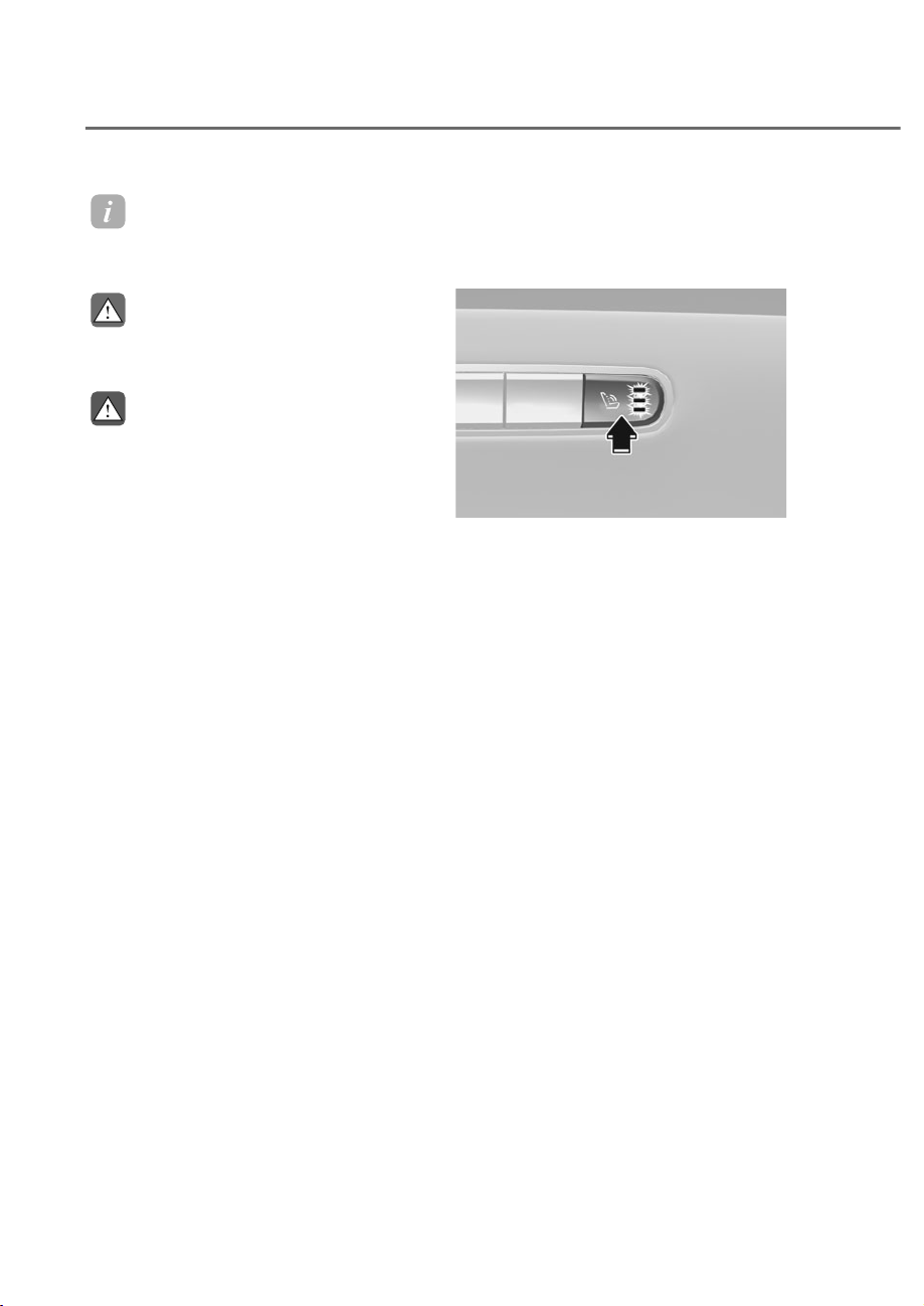
3-22
Safety System
Information
Opening the door will return the calf
support to its original position.
CAUTION
Do not sit or place heavy objects on the
calf support. It may damage the system.
WARNING
• When lowering or raising the calf
support, be careful not to have your
hands or legs caught under the front
seats or other surrounding parts of
the calf support. Unexpected injuries
may occur.
• Do not allow children to adjust the
switch. Unexpected injuries may
occur.
• Make sure that the footrest and calf
support do not interfere with each
other while adjusting. The body parts
or objects may be damaged if it is
caught in the interference.
Rear seat massage function (if
equipped)
Use massage seat to relax after a long
drive, or when resting inside the vehicle.
ORS031033
ORS031033
Massage button
1. While the Engine Start/Stop button is
in ‘ON’ position, press the massage
button on the rear passenger seat
door to start the function.
• The light indicating massage
intensity level illuminates, and the
massage function will start.
2. Press the button again to set the
intensity level.
• Each time you press the button, the
intensity setting of the Massage is
changed as follows:
+LJKɌ0HGLXPɌ/RZɌ2II
• To stop the function, press the
button multiple times until the
indicator light does not illuminate.
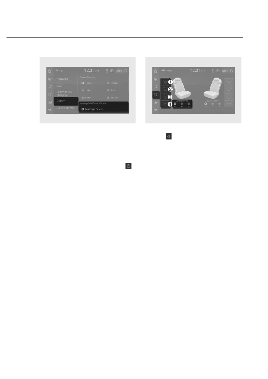
3-23
03
ORS031137L
ORS031137L
Setting the screen display
After pressing the massage button, you
can change the display method of each
massage mode from the armrest touch
screen. Follow the steps below.
1. Press 'Setup' from the home screen on
the armrest touchscreen, or press
from the left side menu.
2. Press 'Display'.
3. Select among 'Massage screen',
'Pop-up', or 'OFF' from the 'Massage
Notification/Status' menu.
• If Massage screen is selected,
pressing the Massage button will
move the armrest touchscreen
display to Massage mode tap.
• If 'Pop-up' is selected, pressing the
massage button will display the
massage mode pop-up screen on
the armrest touchscreen.
ORS031035L
ORS031035L
Armrest touchscreen
1. Press from the left side menu on
the armrest touchscreen.
• Massage mode screen is displayed.
2. Select a desired mode.
M Whole-Body Energizing Mode
N Lumbar Therapy Mode
O Pelvis Balancing Mode
P Upper Body Refresh Mode
3. Select the desired duration.
• Each time you press the button, the
intensity setting of the Massage it is
changed as follows:
+LJKɌ0HGLXPɌ/RZɌ2II
• Massage duration can be set to 10,
15, or 20 minutes.
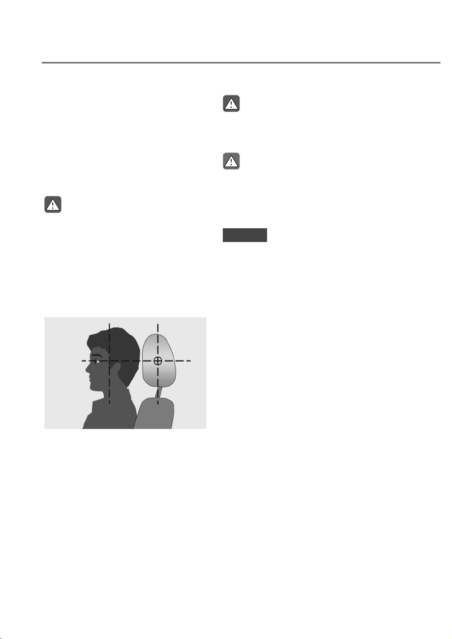
3-24
Safety System
Head Restraint
The vehicle’s front and rear seats
have adjustable head restraints. The
head restraints provide comfort for
passengers, but more importantly they
are designed to help protect passengers
from whiplash and other neck and spinal
injuries during an accident, especially in
a rear impact collision.
WARNING
To reduce the risk of serious injury or
death in an accident, take the following
precautions when adjusting your head
restraints:
• Always properly adjust the head
restraints for all passengers BEFORE
starting the vehicle.
• NEVER let anyone ride in a seat
with the head restraint removed or
reversed.
OJKEV032104L
OJKEV032104L
• Adjust the head restraints so the
middle of the head restraint is at the
same height as the height of the top
of the eyes.
• NEVER adjust the head restraint
position of the driver’s seat when the
vehicle is in motion.
• Adjust the head restraint as close to
the passenger’s head as possible. Do
not use a seat cushion that holds the
body away from the seatback.
• Make sure the head restraint locks
into position after adjusting it.
WARNING
When sitting on the rear seat, do not
adjust the height of the head restraint
to the lowest position.
CAUTION
When there is no occupant in the rear
seats, adjust the height of the head
restraint to the lowest position. The
rear seat head restraint can reduce the
visibility of the rear area.
NOTICE
To prevent damage, NEVER hit or pull
on the head restraint.
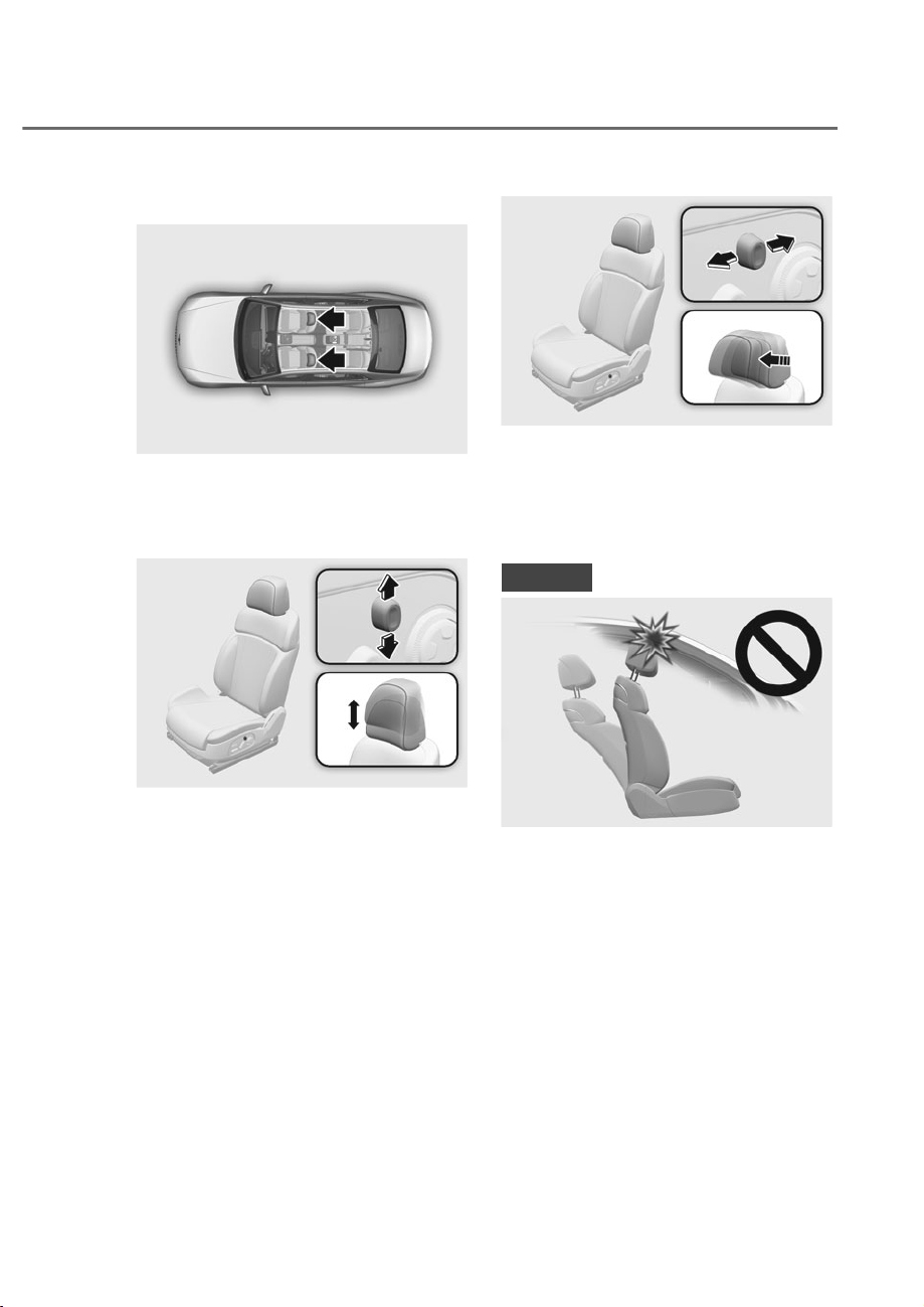
3-25
03
Front seat head restraints
ORS031141L
ORS031141L
The driver’s and front passenger’s seats
are equipped with adjustable head
restraints for the passengers safety and
comfort.
ORS031013
ORS031013
Adjusting the height up and down
1. Push the control switch up to raise or
down to lower the head restraint.
2. Release the switch once the head
restraint reaches the desired position.
ORS031012
ORS031012
Forward and rearward adjustment
1. Push the control switch forward
orrearward to move the head restraint.
2. Release the switch once the head
restraint reaches the desired position.
NOTICE
ORS031131
ORS031131
If you recline the seatback towards the
front with the head restraint and seat
cushion raised, the head restraint may
come in contact with the sunvisor or
other parts of the vehicle.
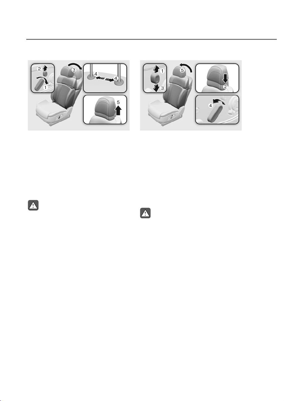
3-26
Safety System
ORS031093
ORS031093
Removal/Reinstall
To remove the head restraint:
1. Recline the seatback O with the
seatback angle switch M.
2. Raise the head restraint as far as it can
go N.
3. Insert a thin-pointed tool into the
head restraint adjustment pole P and
then remove the head restraint Q.
WARNING
NEVER allow anyone to travel in a seat
with the head restraint removed.
ORS031014
ORS031014
To reinstall the head restraint:
1. Recline the seatback.
2. Push the head restraint height control
switch M up as far as it can go.
3. Put the head restraint poles into the
holes N.
4. Adjust the head restraint to the
appropriate height O.
5. Recline the seatback Q using the
seatback angle switch P.
WARNING
Always make sure the head restraint
locks into position after reinstalling and
adjusting it properly.
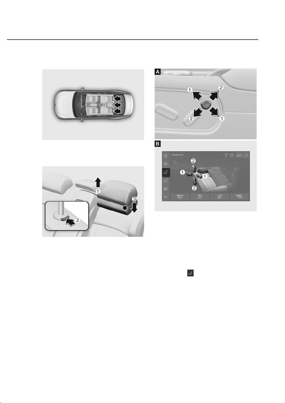
3-27
03
Rear seat head restraints
ORS031029
ORS031029
The rear seats are equipped with head
restraints in all the seating positions for
the passenger’s safety and comfort.
ORS031030
ORS031030
0DQXDODGMXVWPHQWLIHTXLSSHG
• To raise the head restraint:
1. Pull it up to the desired position M.
• To lower the head restraint:
1. Push and hold the release button
N on the head restraint support.
2. Lower the head restraint to the
desired position O.
3RZHUDGMXVWPHQWLIHTXLSSHG
ORS031031
ORS031031
ORS032032N
ORS032032N
• Adjusting the head restraint forward
and rearward M
- Adjustment switch (Type A)
Slide the adjustment switch forward
or backward to adjust the head
restraint forward and rearward.
- Armrest touchscreen (Type B)
1. Press
from the left side menu
on the armrest touchscreen.
- Seat adjustment screen is
displayed.
2. Press the adjustment button on
the upper part of the seat you
want to adjust from the armrest
touchscreen, and then adjust
the head restraint forward and
rearward.
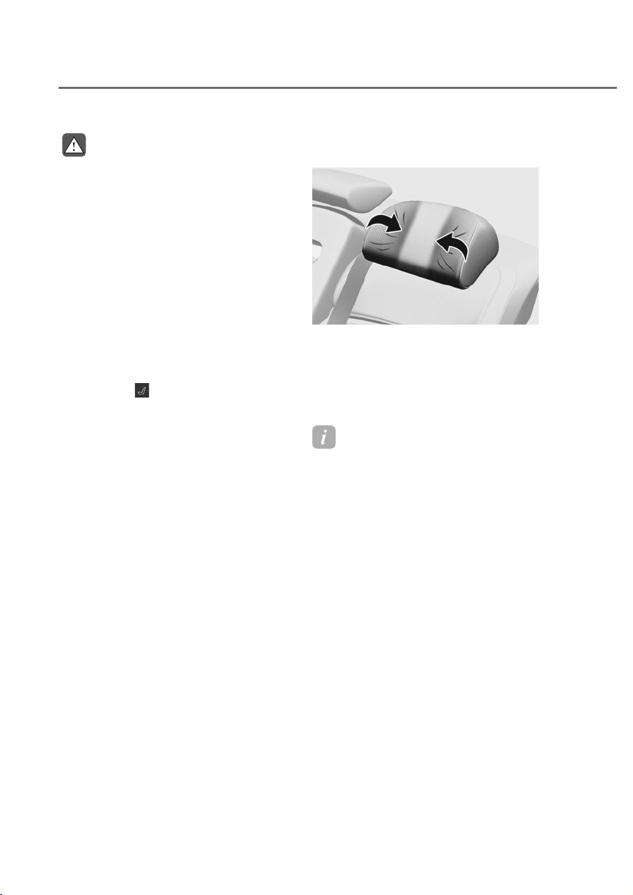
3-28
Safety System
WARNING
Do not remove the head restraint.
Removing the head restraint on your
own might damage the adjustment
motor connector. Have your vehicle
inspected by an authorized retailer
Genesis Branded products.
• Adjusting the height up and down N
- Adjustment switch (Type A)
Push down or pull up the head
restraint adjustment switch to
adjust the head restraint up and
down.
- Armrest touchscreen (Type B)
1. Press
from the left side menu
on the armrest touchscreen.
- Seat adjustment screen is
displayed.
2. Press the adjustment button on
the upper part of the seat you
want to adjust from the armrest
touchscreen, and then adjust the
head restraint up and down.
Wing-out head restraint adjustment
(if equipped)
ORS031036
ORS031036
While driving, the wing-out head
restraint supports the passenger’s head
from shaking. Hold both ends of the
wing-out head restraint with your hands,
and pull out or push in to adjust its
position.
Information
When the wing-out head restraint is not in
use, hold both ends of the head restraint
and pull out to return it to its original
position.
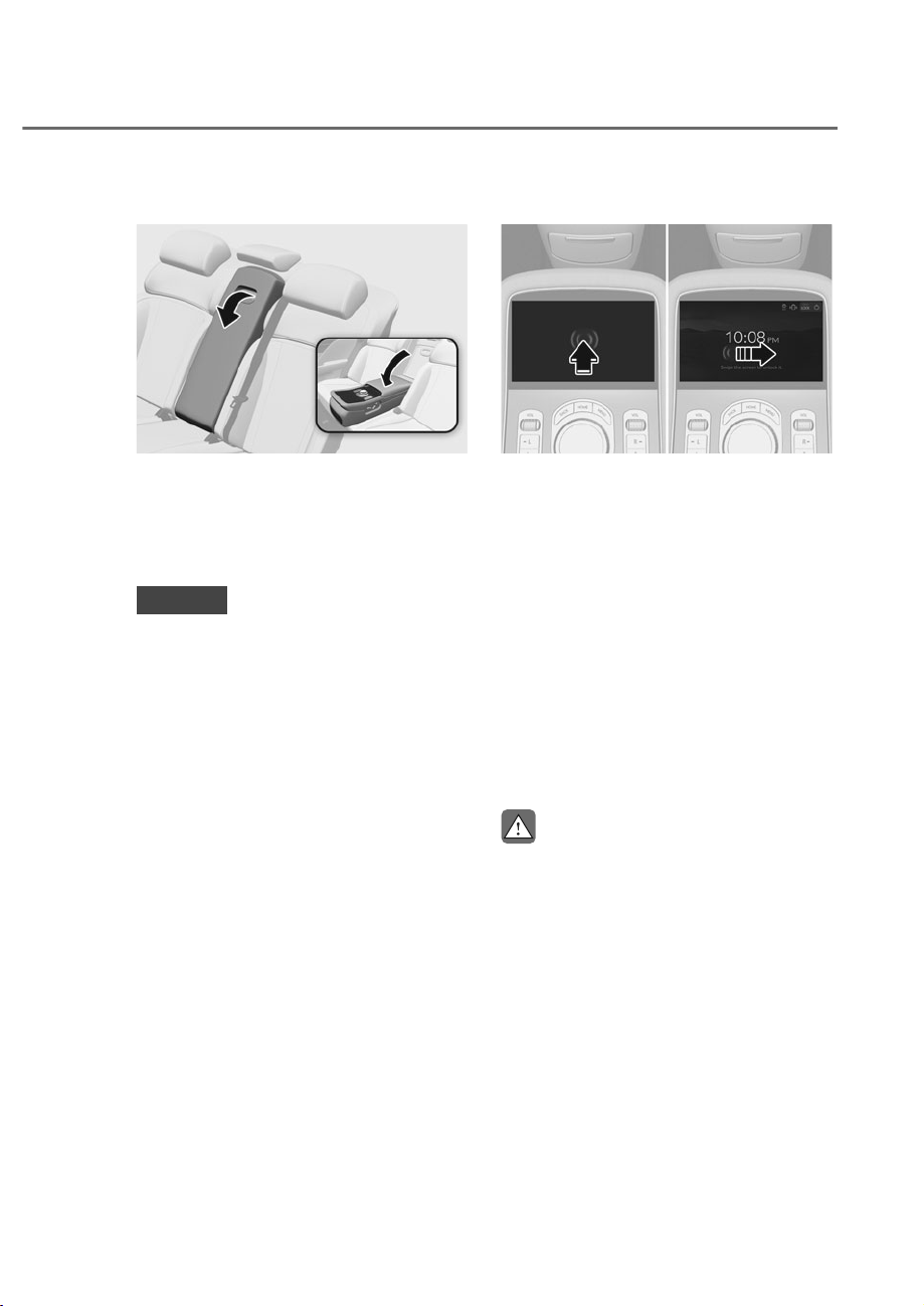
3-29
03
Armrest
ORS031037
ORS031037
The armrest is located in the center of
the rear seat.
Grab the handle on the upper end of the
arm rest. Then, pull down the handle to
use the arm rest.
NOTICE
• Do not put any items on the rear
center seat. Those items may get
damaged, when the arm rest is
pulled down.
• Do not attempt to fold back the
arm rest, when the cup holder is
extended out.
Using the armrest touchscreen
ORS031039L
ORS031039L
Convenience features can be adjusted
using the rear armrest touchscreen.
Quickly touch the screen twice to start
the display. Climate, Seat, Massage,
Lights, and Shades are adjustable from
the armrest touchscreen.
• Pressing the LOCK button on the
upper part of the rear seat armrest
touchscreen will disable the armrest
touchscreen and other infotainment
switches from operating.
Press the LOCK button again to enable
the switches.
• For more information refer to the
“Armrest Touchscreen” section in
chapter 4.
CAUTION
• Keep the armrest cover closed while
driving. Sudden braking may lead to
injuries, by bumping into the armrest
cover.
• Do not forcefully pull the upper part
of the armrest. The Anchor holding
the armrest may be damaged.
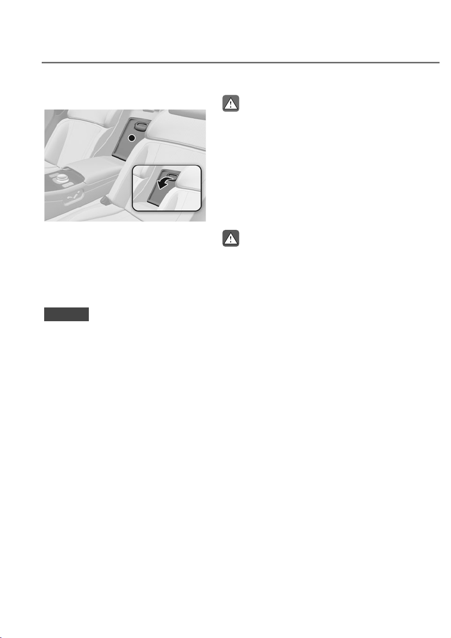
3-30
Safety System
Carrying long/narrow cargo
ORS031038
ORS031038
Additional cargo space is provided to
accommodate long/narrow cargo (skis,
poles, etc.) not able to fit properly in the
trunk when closed.
1. Pull the armrest down.
2. Pull the cover down while pushing the
release lever down.
NOTICE
• Be careful when loading cargo
through the rear passenger seats
to prevent damage to the vehicle
interior.
• When both the armrest and the
panel, which located between the
rear seatback and the trunk for long-
item storage, are folded down, put
back the panel first, before folding
back the arm rest. If not, the panel
knobs and the armrest knobs may
interfere with each other and get
damaged.
CAUTION
• Make sure the engine is off, the
vehicle is shifted to P (Park) and the
parking brake is applied whenever
loading or unloading cargo. The
vehicle may move if the shift lever
is inadvertently moved to another
position.
• When cargo is loaded through the
rear passenger seats, ensure the
cargo is properly secured to prevent
it from moving while driving.
WARNING
Cargo should always be secured to
prevent it from being thrown about the
vehicle in a collision and causing injury
to the vehicle occupants. Do not place
objects in the rear seats, since they
cannot be properly secured and may hit
the front seat occupants in a collision.

3-31
03
Pre-active Safety Seat (PSS) (if
equipped)
When Pre-active Safety Seat detects
a collision or hazardous situation, it
provides safety by repositioning the seat
as follows:
• Seatback (power passenger seat and
rear seat): Raises the seatback when
reclined.
• Seat cushion (power rear seat): If
the cushion height is low, raises the
cushion.
WARNING
Pre-active Safety Seat is a
supplementary device. The driver
should keep their eyes on the road and
verify that there are no obstructions
ahead. If there are no passengers or the
seatbelts are not fastened, the system
will not function.
System operation
• Pre-active Safety Seat limits
passenger’s movement and helps
decrease the chance of injury by
raising the seatback right before
collision to tighten the seatbelt.
The system may operate under the
following situations:
- The brake pedal was depressed
abruptly.
- The vehicle is difficult to control.
- Collision risk is considered high by
the vehicle distance sensor.
• Pre-active Safety Seat helps prevent
the passenger from leaning forward
or to the side by raising the seatback
during sudden braking or rapid
turning to tighten the seatbelt.
The system may operate under the
following situations:
- The upper body is leaned forward
due to sudden braking.
- The upper body is leaned to the side
due to rapid turning.
- Driving on a slippery icy road.
- There is high risk of a rollover.
System pause
If the passenger adjusts the seat
manually, the system stops immediately.
However, it restarts to operate after 5
seconds when the hazardous situation
continues.
System malfunction
If the Pre-active Safety Seat system does
not operate properly, have the vehicle
inspected by an authorized retailer of
Genesis Branded products.

3-32
Safety System
Seat Warmers
Seat warmers are provided to warm the
seats during cold weather.
During mild weather or under conditions
where the operation of the seat warmer
is not needed, keep the seat warmers
OFF.
WARNING
The seat warmers can cause a SERIOUS
BURN, even at low temperatures and
especially if used for long periods of
time.
Passengers must be able to feel if the
seat is becoming too warm so they can
turn it off, if needed.
People who cannot detect temperature
change or pain to the skin should
use extreme caution, especially the
following types of passengers:
• Infants, children, elderly or disabled
persons, or hospital outpatients.
• People with sensitive skin or who
burn easily.
• Fatigued individuals.
• Intoxicated individuals.
• People taking medication that can
cause drowsiness or sleepiness.
WARNING
NEVER place anything on the seat
that insulates against heat when the
seat warmer is in operation, such as a
blanket or seat cushion. This may cause
the seat warmer to overheat, causing a
burn or damage to the seat.
NOTICE
To prevent damage to the seat warmers
and seats:
• Never use a solvent such as paint
thinner, benzene, alcohol or gasoline
to clean the seats.
• Do not place heavy or sharp objects
on seats equipped with seat
warmers.
• Do not change the seat cover. It may
damage the seat warmer.
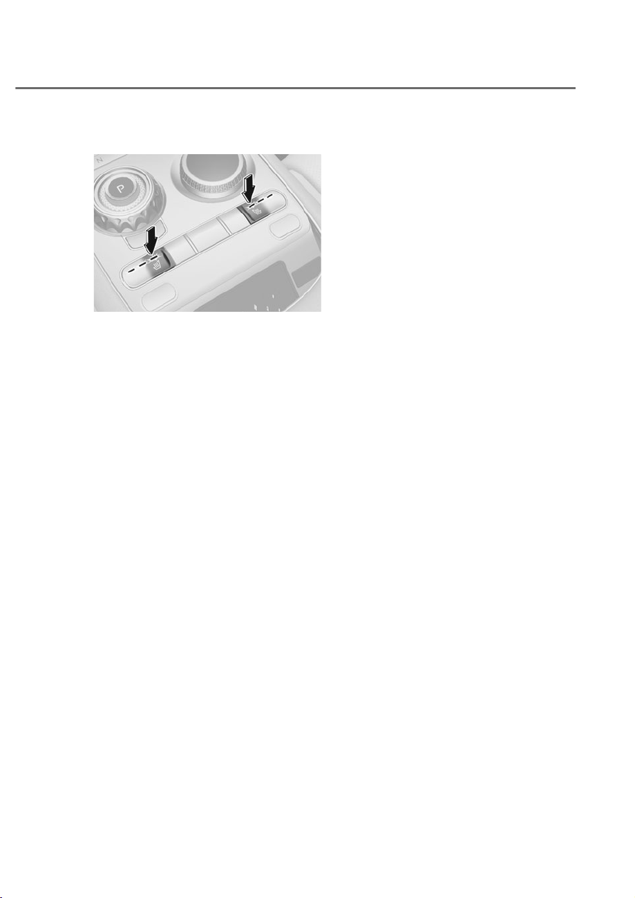
3-33
03
Front seat warmers
ORS031040
ORS031040
While the engine is on, press the seat
heater button on the center console to
select the temperature level.
• Temperature level can be adjusted to
strong, medium, or weak. Pressing
the button each time will change the
temperature in turn from strong, to
medium, weak, and off.
• Press and hold the seat heater button
to turn it off.
• Automatic Controls Linked to Climate
Control Settings (for driver’s seat)
The seat warmer automatically
controls the seat temperature
depending on the ambient
temperature when the engine is
running.
To use this function, it must be
enabled from the Settings menu in the
infotainment system screen. Select:
- 6HWXSɌ9HKLFOHɌ6HDWɌ:DUPHU
9HQWLODWLRQ)HDWXUHVɌ$XWRPDWLF
Controls Linked to Climate Control
6HWWLQJVɌ'ULYHU6HDW:DUPHU
Ventilation
• Seat Warmer Balance
You may lower the seat warmer
setting, or may turn the seat warmer
off for either the seatback or seat
cushion, when the seat warmer is on.
To use this function, it must be
enabled from the Settings menu in the
infotainment system screen. Select:
- 6HWXSɌ9HKLFOHɌ6HDWɌ:DUPHU
9HQWLODWLRQ)HDWXUHVɌ6HDW:DUPHU
Balance
• When touching the icon for more than
1.5 seconds with the seat warmer
operating, the seat warmer will turn
OFF.
• The seat warmer defaults to the
OFF position whenever the Engine
Start/Stop button is pressed to
the ON position. However, if the
Automatic Controls Linked to Climate
Control Settings function is ON, the
driver’s seat warmer will turn on
and off depending on the ambient
temperature.
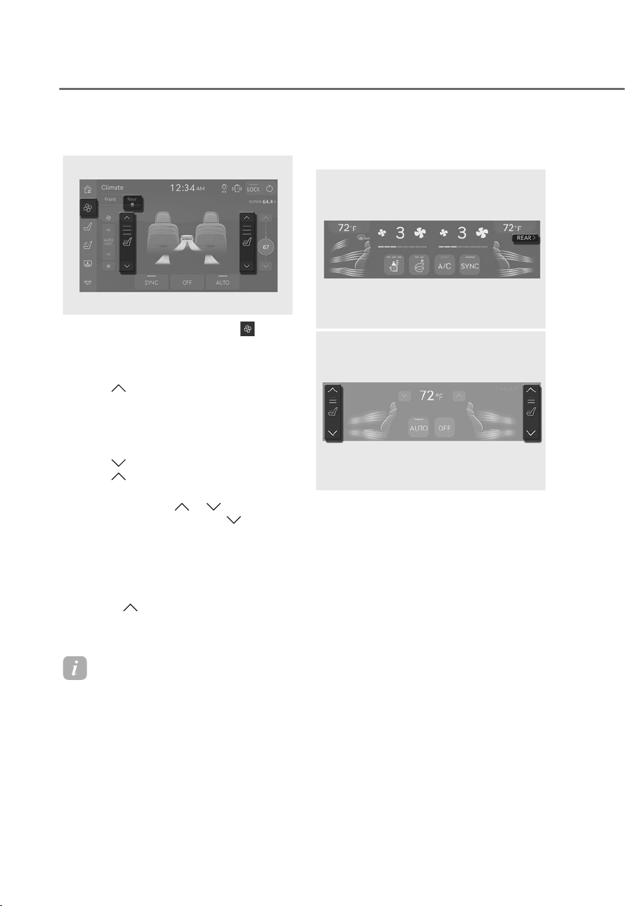
3-34
Safety System
Rear seat warmers (if equipped)
ORS032042N
ORS032042N
1. While the engine is on, press
button from the left side menu on the
armrest touchscreen.
• Climate screen is displayed.
2. Press
next to the seat which
requires heating, from the air
conditioning screen.
• Seat heater is turned on with strong
temperature level.
3. Press
to lower the temperature.
Press
to raise the temperature
again.
• Press and hold
or to turn off
the seat heater, or press
multiple
times until it turns off.
• Seat heater automatically turns off
once the temperature reaches the
limit, and turns on again when the
temperature drops.
• Press
multiple times to turn
on the seat heater when the seat
ventilator is on. (if equipped)
Information
• After a certain period of time, the
temperature level of the seat heater is
automatically lowered to prevent low
temperature burns.
• ,IWKHHQJLQHLVWXUQHGRIIZKLOHWKH
seat heater is on, the seat heater will be
turned off after the engine is restarted.
Using rear seat heaters from front
seat
ORS032108N
ORS032108N
ORS032043N
ORS032043N
Rear seat heaters can be turned on/off
from the front seat.
1. Press REAR from the upper part of
the air conditioning display while the
engine is on.
• Rear seat air conditioning screen is
displayed.

3-35
03
2. Press next to the seat which
requires heating, from the air
conditioning screen.
• Seat heater is turned on with strong
temperature level.
3. Press
to lower the temperature.
Press
to raise the temperature
again.
• Press and hold
or to turn off
the seat heater, or press
multiple
times until it turns off.
• Seat heater automatically turns off
once the temperature reaches the
limit, and turns on again when the
temperature drops.
• Press
multiple times to turn
on the seat heater when the seat
ventilator is on. (if equipped)
Air Ventilation Seats
The air ventilation seats are provided
to cool the front seats by blowing air
through small vent holes on the surface
of the seat cushions and seatbacks.
When the operation of the air ventilation
seat is not needed, keep the air
ventilation seats OFF.
NOTICE
To prevent damage to the air ventilation
seats:
• Never use a solvent such as paint
thinner, benzene, alcohol or gasoline
to clean the seats.
• Avoid spilling liquids on the surface
of the front seats and seatbacks;
this may cause the air vent holes
to become blocked and not work
properly.
• Do not place materials such as
plastic bags or newspapers under
the seats. They may block the air
intake causing the air vents to not
work properly.
• Do not change the seat covers. It may
damage the air ventilation seat.
• If the air vents do not operate, restart
the vehicle. If there is no change,
we recommend that you have your
vehicle inspected by an authorized
retailer of Genesis Branded products.
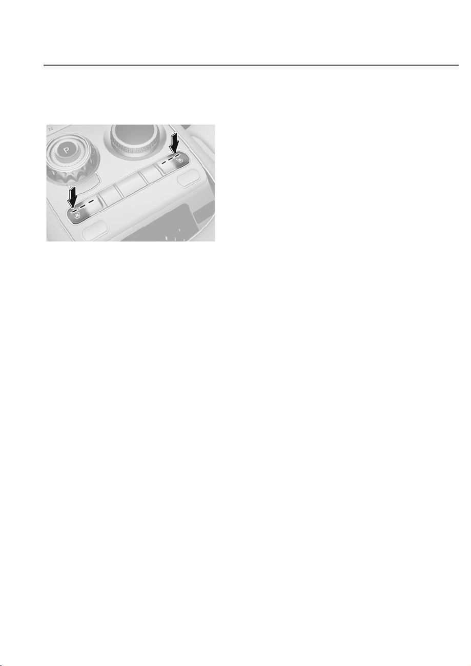
3-36
Safety System
Front air ventilation seats (if
equipped)
ORS031041
ORS031041
While the engine is on, press the seat
ventilator button on the center console
to select the intensity level.
• Ventilation intensity level can be
adjusted to strong, medium, or weak.
Pressing the button each time will
change the intensity in turn from
strong, to medium, weak, and off.
• Press and hold the seat ventilator
button to turn it off.
• Automatic Controls Linked to Climate
Control Settings (for driver’s seat)
The air ventilation seat automatically
controls the seat temperature
depending on the ambient
temperature when the engine is
running.
To use this function, it must be
enabled from the Settings menu in the
infotainment system screen. Select:
- 6HWXSɌ9HKLFOHɌ6HDWɌ:DUPHU
9HQWLODWLRQ)HDWXUHVɌ$XWRPDWLF
Controls Linked to Climate Control
6HWWLQJVɌ'ULYHU6HDW:DUPHU
Ventilation
• When touching the icon for more than
1.5 seconds with the air ventilation
seat operating, the operation will turn
OFF.
• The air ventilation seats defaults
to the OFF position whenever the
Engine Start/Stop button is pressed
to the ON position. However, if the
Automatic Controls Linked to Climate
Control Settings function is ON, the
driver’s seat warmer will turn on
and off depending on the ambient
temperature.
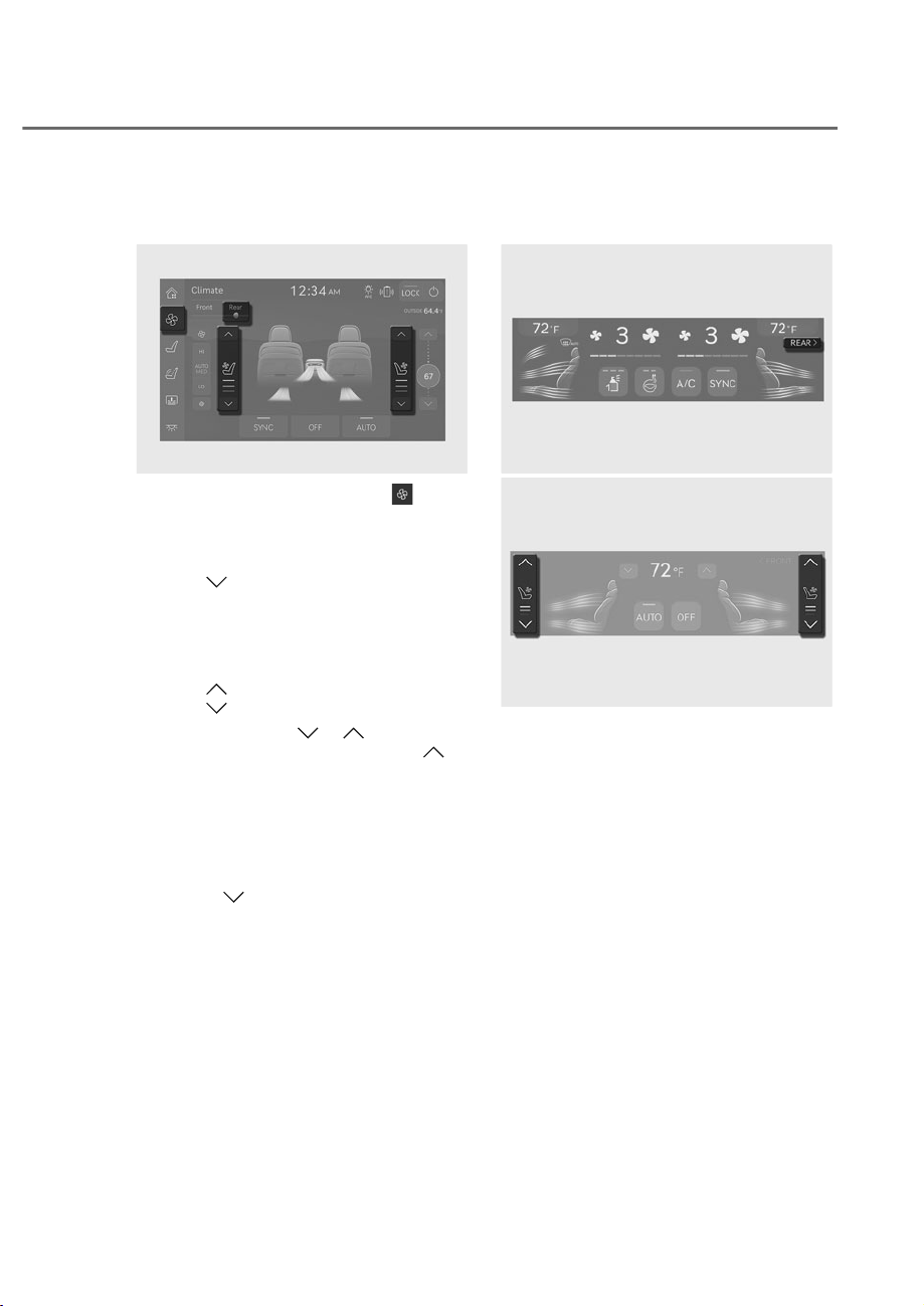
3-37
03
Rear air ventilation seats
(if equipped)
ORS032044N
ORS032044N
1. While the engine is on, press
button from the left side menu on the
armrest touchscreen.
• Climate screen is displayed.
2. Press
next to the seat which
requires ventilating, from the air
conditioning screen.
• Seat ventilator is turned on with
strong intensity level.
3. Press
to lower ventilation intensity.
Press
to raise intensity again.
• Press and hold
or to turn
off the seat ventilator, or press
multiple times until it turns off.
• Seat ventilator automatically turns
off once the seat temperature
falls below a certain temperature,
and turns on again when the
temperature rises.
• Press multiple times to turn on
the seat ventilator when the seat
heater is on. (if equipped)
Using the rear seat ventilator from
the front seat (if equipped)
ORS032108N
ORS032108N
ORS032045N
ORS032045N
Rear seat ventilators can be turned on/
off from the front seat.
1. Press REAR from the upper part of
the air conditioning display while the
engine is on.
• Rear seat air conditioning screen is
displayed.

3-38
Safety System
2. Press next to the seat which
requires ventilating, from the air
conditioning screen.
• Seat ventilator is turned on with
strong intensity level.
3. Press
to lower the ventilation
intensity. Press
to raise intensity
again.
• Press and hold
or to turn
off the seat ventilator, or press
multiple times until it turns off.
• Seat ventilator automatically turns
off once the seat temperature
falls below a certain temperature,
and turns on again when the
temperature rises.

3-39
03
SEAT BELTS
This section describes how to use the
seat belts properly. It also describes
some of the things not to do when using
seat belts.
Seat Belt Safety Precautions
Always fasten your seat belt and make
sure all passengers have fastened their
seat belts before starting any trip. Air
bags are designed to supplement the
seat belt as an additional safety device,
but they are not a substitute. Most states
require all occupants of a vehicle to wear
seat belts.
WARNING
Seat belts must be used by ALL
passengers whenever the vehicle is
moving. Take the following precautions
when adjusting and wearing seat belts:
• Children under the age of 13 should
be properly restrained in the rear
seats.
• Never allow children to ride in the
front passenger seat, unless the
air bag is deactivated. If a child is
seated move the seat as far back as
possible. And the child must always
be restrained in the seat properly.
• NEVER allow an infant or child to be
carried on an occupant’s lap.
• NEVER ride with the seatback
reclined when the vehicle is moving.
• Do not allow children to share a seat
or seat belt.
• Do not wear the shoulder belt under
your arm or behind your back.
• Never wear a seat belt over fragile
objects. If there is a sudden stop or
impact, the seat belt can damage it.
• Do not use the seat belt if it is
twisted. A twisted seat belt will not
protect you properly in an accident.
• Do not use a seat belt if the webbing
or hardware is damaged.
• Do not latch the seat belt into the
buckles of other seats.
• NEVER unfasten the seat belt
while driving. This may cause loss
of vehicle control resulting in an
accident.
• Make sure there is nothing in the
buckle interfering with the seat
belt latch mechanism, because any
materials in the buckle can cause the
seat belt not to be fastened securely.
• No modifications or additions
should be made by the user which
will either prevent the seat belt
adjusting devices from operating to
remove slack, or prevent the seat
belt assembly from being adjusted to
remove slack.
WARNING
Damaged seat belts and seat belt
assemblies will not operate properly.
Always replace:
• Frayed, contaminated, or damaged
webbing.
• Damaged hardware.
• The entire seat belt assembly after it
has been worn in an accident, even
if damage to webbing or assembly is
not apparent.
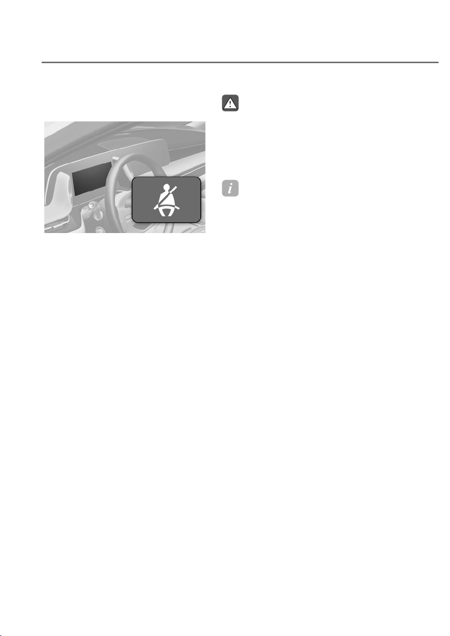
3-40
Safety System
Seat Belt Warning Light
Front seat belt warning
ORS031046
ORS031046
As a reminder to the driver and front
passenger, the seat belt warning light will
illuminate for approximately 6 seconds
each time the Engine Start/Stop button
is in the ON position regardless of belt
fastening.
If the seat belt is not fastened, the
warning chime will sound for about 6
seconds and the waning light will stay
ON until the seat belt is fastened.
If the seat belt is not fastened, when
vehicle speed is between 5.5 mph (9
km/h) and 12 mph (20 km/h) the warning
light will continue to illuminate and
warning chime will sound until the seat
belt is fastened.
If the seat belt is not fastened, when
vehicle speed is above 12 mph (20 km/h),
the warning light will blink and warning
chime will sound for approximately 100
seconds. (warning chime will sound in
three stages)
WARNING
Riding in an improper position
adversely affects the front passenger’s
seat belt warning system. It is important
for the driver to instruct the passenger
to be seated properly as instructed in
this manual.
Information
• Although the front passenger seat is not
occupied, the seat belt warning light
will blink or illuminate for 6 seconds.
• The front passenger’s seat belt warning
may operate when luggage is placed on
the front passenger seat.
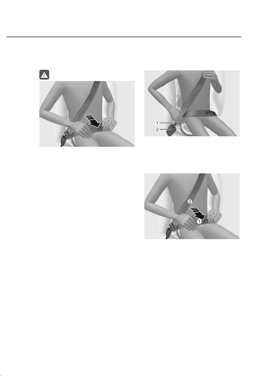
3-41
03
Seat Belt Restraint System
WARNING
ORS031127
ORS031127
Improperly positioned seat belts may
increase the risk of serious injury
in an accident. Take the following
precautions when adjusting the seat
belt:
• Position the lap portion of the seat
belt as low as possible across your
hips, not on your waist, so that it
fits snugly. This allows your strong
pelvic bones to absorb the force of
the crash, reducing the chance of
internal injuries.
• Position one arm under the shoulder
belt and the other over the belt, as
shown in the illustration.
• Always position the shoulder belt
anchor into the locked position at the
appropriate height.
• Never position the shoulder belt
across your neck or face.
Seat Belt-Driver’s 3-point System
with Emergency Locking Retractor
ORS031126
ORS031126
To fasten your seat belt:
Pull it out of the retractor and insert the
metal tab M into the buckle N. There will
be an audible “click” when the tab locks
into the buckle.
ORS031130
ORS031130
You should place the lap belt M portion
across your hips and the shoulder belt N
portion across your chest.
The seat belt automatically adjusts to the
proper length after the lap belt portion
is adjusted manually so that it fits snugly
around your hips. If you lean forward in
a slow, easy motion, the belt will extend
and move with you.
If there is a sudden stop or impact, the
belt will lock into position. It will also lock
if you try to lean forward too quickly.
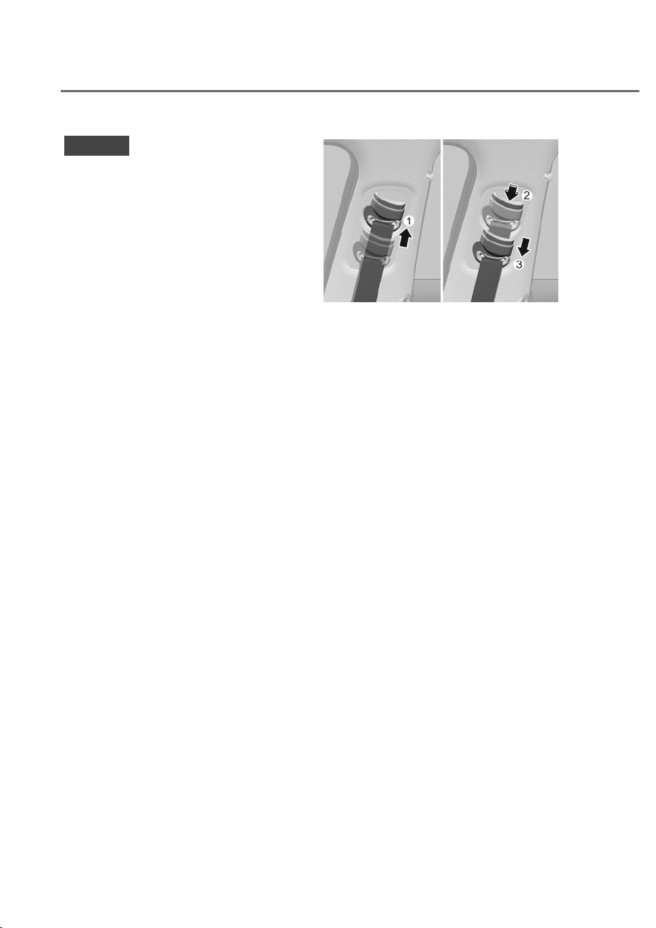
3-42
Safety System
NOTICE
If you are not able to smoothly pull
enough of the seat belt out from the
retractor, firmly pull the seat belt out
and release it. After release, you will be
able to pull the belt out smoothly.
Height adjustment
You can adjust the height of the shoulder
belt anchor to one of the four different
positions for maximum comfort and
safety.
The shoulder portion should be adjusted
so it lies across your chest and midway
over your shoulder nearest the door, not
over your neck.
ORS031047
ORS031047
Front seat:
To adjust the height of the seat belt
anchor, lower or raise the height adjuster
into an appropriate position.
To raise the height adjuster, pull it up
M. To lower it, push it down O while
pressing the height adjuster button N.
Release the button to lock the anchor
into position. Try sliding the height
adjuster to make sure that it has lock into
position.
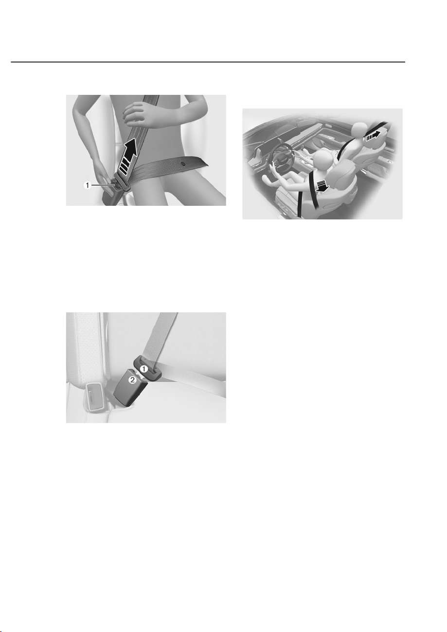
3-43
03
ORS031128
ORS031128
To release your seat belt:
Press the release button M in the locking
buckle.
When it is released, the belt should
automatically draw back into the
retractor. If this does not happen, check
the belt to be sure it is not twisted, then
try again.
Rear center seat belt (if equipped)
ORS031048L
ORS031048L
1. Take out the buckle N, which is stored
between the seat/seatback cushions.
2. Insert the metal plate M into the
buckle N, until it clicks.
You can make sure its secure
fastening by pulling the seatbelt
webbing. The buckle with ‘CENTER’
mark should be used for the 3-point
seatbelt.
3. Restore the buckle between the seat/
seatback cushion after unfastening
the seatbelt.
Pre-tensioner seat belt
ORS031103
ORS031103
Your vehicle is equipped with driver’s and
front passenger’s and rear passengers
Pre-tensioner Seat Belts (Retractor
Pre-tensioner). The purpose of the pre-
tensioner is to make sure the seat belts
fit tightly against the occupant’s body
in certain frontal or side collision(s).
The pre-tensioner seat belts may be
activated in crashes where the frontal
or side collision(s) is severe enough,
together with the air bags.
When the vehicle stops suddenly, or if
the occupant tries to lean forward too
quickly, the seat belt retractor will lock
into position.
In certain frontal collisions, the pre-
tensioner will activate and pull the seat
belt into tighter contact against the
occupant’s body.
If the system senses excessive tension
on the driver or passenger’s seat belt
when the pre-tensioner system activates,
the load limiter inside the retractor
pre-tensioner will release some of the
pressure on the affected seat belt.
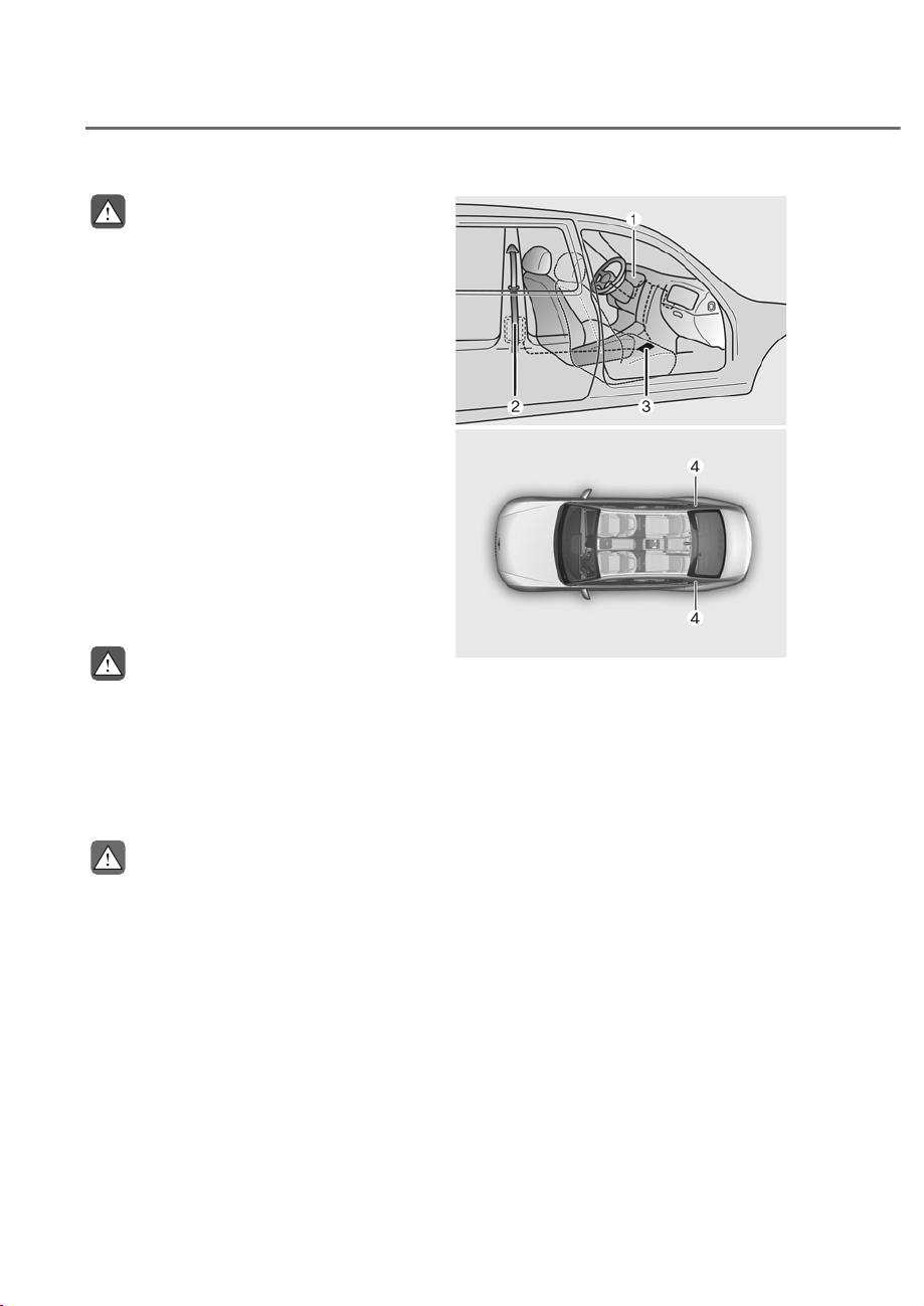
3-44
Safety System
WARNING
• Always wear your seat belt and sit
properly in your seat.
• Do not use the seat belt if it is loose
or twisted. A loose or twisted seat
belt will not protect you properly in
an accident.
• Do not place anything near the
buckle. This may adversely affect
the buckle and cause it to function
improperly.
• Always replace your pre-tensioners
after activation or an accident.
• NEVER inspect, service, repair
or replace the pre-tensioners by
yourself. Have the pre-tensioners
inspected, serviced, repaired or
replaced by an authorized retailer of
Genesis Branded products.
• Do not hit the seat belt assemblies.
WARNING
Do not touch the pre-tensioner seat
belt assemblies for several minutes
after they have been activated. When
the pre-tensioner seat belt mechanism
deploys during a collision, the pre-
tensioner can become hot and can burn
you.
CAUTION
Body work on the front area of the
vehicle may damage the pre-tensioner
seat belt system. Therefore, have the
system serviced by an authorized
retailer of Genesis Branded products.
ODN8H033057
ODN8H033057
ORS031144L
ORS031144L
The Pre-Tensioner Seat Belt System
consists mainly of the following
components. Their locations are shown
in the illustration above:
M SRS air bag warning light
N Retractor pre-tensioner
O SRS control module
P
Rear Retractor pre-tensioner (if
equipped)

3-45
03
NOTICE
The sensor that activates the SRS
control module is connected with the
pre–tensioner seat belts. The SRS air
bag warning light on the instrument
cluster will illuminate for approximately
three to six seconds after the Engine
Start/Stop button is in the ON position,
and then it should turn off.
If the pre-tensioner is not working
properly, the warning light will
illuminate even if the SRS air bag is not
malfunctioning. If the warning light
does not illuminate, stays illuminated
or illuminates when the vehicle is being
driven, have the pre-tensioner seat
belts and/or SRS control module be
inspected by an authorized retailer of
Genesis Branded products as soon as
possible.
Information
• Pre-tensioner seat belts may be
activated in certain frontal or side
collisions or rollover situations.
• When the pre-tensioner seat belts are
activated, a loud noise may be heard
and fine dust, which may appear to be
smoke, may be visible in the passenger
compartment. These are normal
operating conditions and are not
hazardous.
• Although it is non-toxic, the fine dust
may cause skin irritation and should
not be inhaled for prolonged periods.
Wash all exposed skin areas thoroughly
after an accident in which the pre-
tensioner seat belts were activated.
WARNING
• Fasten your seat belt while sitting
properly in an upright position to
maximize the effectiveness of the
pre-tensioner seat belt system.
• A pre-tensioner seat belt system
is designed to activate only once.
Replace the pre-tensioner seat belt
system, if it was activated in an
accident.
Pre-Active Seat Belt (PSB)
(if equipped)
The purpose of the Pre-Active Seat Belt is
to tighten the seat belt when a collision
is sensed, during emergency braking, or
when a loss of control is sensed.
NOTICE
Pre-Active Seat Belt is a supplementary
system. Pre-Active Seat Belt activates
only when the passenger is wearing his/
her seat belt.
Pre-Active Seat Belt operation
In order to maximize the safety of the
passenger, Pre-Active Seat Belt system
operates as below.
• Full retraction
The seat belt is tightened when:
- Emergency braking situation occurs
- Losing control of the vehicle
- The vehicle senses a collision
- Driving on a slippery frozen road
- Unstable rolling of the vehicle
occurs
• Slack removal
Tightens a lose seat belt when
the seatbelt is fastened.
• Belt parking
Tightens a loose seat belt when the
seat belt is unfastened.

3-46
Safety System
Warning message
ORS032152L
ORS032152L
Check Pre-Active Seat Belt
The Pre-Active Seat Belt warning
message will appear if there is a problem
with your Pre-Active Seat Belt.
Have the system checked by an
authorized retailer of Genesis Branded
products if the warning message
comes on while the vehicle is in motion.
When the Pre-Active Seat Belt warning
message disappears, the master warning
light (
) will illuminate.
Additional Seat Belt Safety
Precautions
Seat belt use during pregnancy
The seat belt should always be used
during pregnancy. The best way to
protect your unborn child is to protect
yourself by always wearing the seat belt.
Pregnant women should always wear
a lap-shoulder seat belt. Place the
shoulder belt across your chest, routed
between your breasts and away from
your neck. Place the lap belt below your
belly so that it fits SNUGLY across your
hips and pelvic bone, under the rounded
part of the belly.
WARNING
• Pregnant woman are more
vulnerable to any impacts on the
abdomen during an abrupt stop or
accident. If you are in an accident
while pregnant, consult your doctor.
• To reduce the risk of serious injury or
death to an unborn child during an
accident, pregnant women should
NEVER place the lap portion of the
seat belt above or over the area of
the abdomen where the unborn child
is located.

3-47
03
Seat belt use and children
,QIDQWDQGVPDOOFKLOGUHQ
All 50 states have child restraint laws
which require children to travel in
approved child restraint devices,
including booster seats. The age at
which seat belts can be used instead
of child restraints differs among states,
so you should be aware of the specific
requirements in your state, and where
you are travelling. Infant and child
restraints must be properly placed
and installed in a rear seat. For more
information refer to the “Child Restraint
Systems” section in this chapter.
WARNING
ALWAYS properly restrain infants and
small children in a Child Restraint
System appropriate for the child’s
height and weight.
To reduce the risk of serious injury or
death to a child and other passengers,
NEVER hold a child in your lap or arms
when the vehicle is moving. The violent
forces created during an accident will
tear the child from your arms and throw
the child against the interior of the
vehicle.
Small children are best protected
from injury in an accident when
properly restrained in the rear seat
by a child restraint system that meets
the requirements of the Federal Motor
Vehicle Safety Standards. Before buying
any child restraint system, make sure
that it has a label certifying that it meets
Federal Motor Vehicle Safety Standard
FMVSS 213. The restraint must be
appropriate for your child’s height and
weight. Check the label on the child
restraint for this information. Refer to the
“Child Restraint Systems” section in this
chapter.
Larger children
Children under age 13 who are too large
for a booster seat should always occupy
the rear seat and use the available lap/
shoulder belts. A seat belt should lie
across the upper thighs and be snug
across the shoulder and chest to
restrain the child safely. Check belt fit
periodically. A child’s squirming could
put the belt out of position. In the event
of an accident, children are afforded the
best safety restrained by a proper Child
Restraint System in the rear seats.
If a larger child over age 13 must be
seated in the front seat, the child must
be securely restrained by the available
lap/shoulder belt and the seat should be
placed in the rearmost position.
If the shoulder belt portion slightly
touches the child’s neck or face, try
placing the child closer to the center
of the vehicle. If the shoulder belt still
touches their face or neck, they need to
be returned to an appropriate booster
seat in the rear seat.
WARNING
• Always make sure larger children’s
seat belts are worn and properly
adjusted.
• NEVER allow the shoulder belt to
contact the child’s neck or face.
• Do not allow more than one child to
use a single seat belt.

3-48
Safety System
Seat belt use and injured people
A seat belt should be used when an
injured person is being transported.
Consult a physician for specific
recommendations.
One person per belt
Two people (including children) should
never attempt to use a single seat belt.
This could increase the severity of
injuries in case of an accident.
Do not lie down
Sitting in a reclined position when the
vehicle is in motion can be dangerous.
Even when buckled up, the protections
of your restraint system (seat belts
and/or air bags) is greatly reduced by
reclining your seatback.
Seat belts must be snug against your
hips and chest to work properly.
During an accident, you could be thrown
into the seat belt, causing neck or other
injuries.
The more the seat back is reclined, the
greater the chance for the passenger’s
hips to slide under the lap belt or the
passenger’s neck to strike the shoulder
belt.
WARNING
• NEVER ride with a reclined seatback
when the vehicle is moving.
• Riding with a reclined seatback
increases your chance of serious
or fatal injuries in the event of a
collision or sudden stop.
• Driver and passengers should always
sit well back in their seats with the
seatbacks upright and should be
belted properly.
Care of Seat Belts
Seat belt systems should never be
disassembled or modified. In addition,
care should be taken to assure that seat
belts and belt hardware are not damaged
by seat hinges, doors or other abuse.
Periodic inspection
All seat belts should be inspected
periodically for wear or damage of any
kind. Any damaged parts should be
replaced as soon as possible.
Keep belts clean and dry
Seat belts should be kept clean and
dry. If belts become dirty, they can be
cleaned by using a mild soap solution
and warm water. Bleach, dye, strong
detergents or abrasives should not be
used because they may damage and
weaken the fabric.
When to replace seat belts
The entire seat belt assembly or
assemblies should be replaced if the
vehicle has been involved in an accident.
This should be done even if no damage is
visible. Consult an authorized retailer of
Genesis Branded products.

3-49
03
&+,/'5(675$,176<67(0ʚ&56ʛ
Our Recommendation: Children
Always In the Rear
WARNING
Always properly restrain children in the
rear seats of the vehicle.
Children of all ages are safer when
restrained in the rear seat. A child riding
in the front passenger seat can be
forcefully struck by an inflating air bag
resulting in SERIOUS INJURY or DEATH.
Children under age 13 must always
ride in the rear seats and must always
be properly restrained to minimize the
risk of injury in an accident, sudden
stop or sudden maneuver. According
to accident statistics, children are safer
when properly restrained in the rear
seats than in the front seat. Even with
air bags, children can be seriously
injured or killed. Children too large for
a child restraint must use the seat belts
provided.
All 50 states have child restraint laws
which require children to travel in
approved child restraint devices. The
laws governing the age or height/weight
restrictions at which seat belts can be
used instead of child restraints differs
among states, so you should be aware of
the specific requirements in your state,
and where you are travelling.
Child restraint systems must be properly
placed and installed in the rear seat.
You must use a commercially available
child restraint system that meets the
requirements of the Federal Motor
Vehicle Safety Standards (FMVSS 213).
Child restraint systems are generally
designed to be secured in a vehicle seat
by lap belt portion of a lap/shoulder belt,
or by a LATCH system in the rear seats of
the vehicle.
Child restraint system (CRS)
Infants and younger children must be
restrained in an appropriate rear-facing
or forward-facing CRS that has first
been properly secured to the rear seat
of the vehicle. Read and comply with
the instructions for installation and use
provided by the manufacturer of the
child restraint.
WARNING
An improperly secured child restraint
can increase the risk of SERIOUS
INJURY or DEATH in an accident. Always
take the following precautions when
using a child restraint system:
• NEVER install a child or infant
restraint in the front passenger’s
seat.
• Always properly secure the child
restraint to a rear seat of the vehicle.
• Always follow the child restraint
system manufacturer’s instructions
for installation and use.
• Always properly restrain your child in
the child restraint.
• If the vehicle head restraint prevents
proper installation of a child seat
(as described in the child restraint
system manual), the head restraint of
the respective seating position shall
be readjusted or entirely removed.
• Do not use an infant carrier or a
child safety seat that “hooks” over
a seatback, it may not provide
adequate protection in an accident.
• After an accident, have retailer of
Genesis Branded products check
the child restraint system, seat belts,
tether anchors and lower anchors.
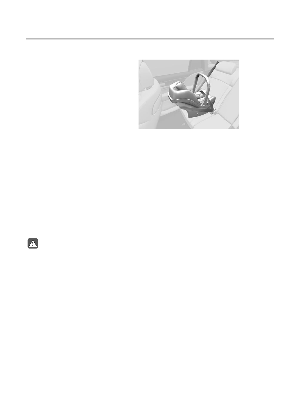
3-50
Safety System
Selecting a Child Restraint
System (CRS)
When selecting a Child Restraint System
for your child, always:
• Make sure the CRS has a label
certifying that it meets applicable
Federal Motor Vehicle Safety
Standards (FMVSS 213).
• Select a Child Restraint System based
on your child’s height and weight. The
required label or the instructions for
use typically provide this information.
• Select a Child Restraint System that
fits the vehicle seating position where
it will be used.
• Read and comply with the warnings
and instructions for installation and
use provided with the Child Restraint
System.
Child Restraint System types
There are three main types of Child
Restraint Systems: rearward-facing,
forward-facing and booster Child
Restraint Systems.
They are classified according to the
child’s age, height and weight.
WARNING
NEVER install a child or infant restraint
in the front passenger’s seat.
Placing a rear-facing child restraint in
the front seat can result in SERIOUS
INJURY or DEATH if the child restraint is
struck by an inflating air bag.
ORS031049
ORS031049
Rear-facing child seats
A rear-facing child seat provides restraint
with the seating surface against the back
of the child. The harness system holds
the child in place, and in an accident,
acts to keep the child positioned in the
seat and reduce the stress to the neck
and spinal cord.
All children under age one must always
ride in a rear-facing infant child restraint.
Convertible and 3-in-1 child seats
typically have higher height and weight
limits for the rear-facing position,
allowing you to keep your child rear-
facing for a longer period of time.
Continue to use a rear-facing child seat
for as long as your child will fit within the
height and weight limits allowed by the
child seat manufacturer. It’s the best way
to keep them safe. Once your child has
outgrown the rear-facing child restraint,
your child is ready for a forward-facing
child restraint with a harness.

3-51
03
ORS031050
ORS031050
Forward-facing Child Restraint System
A forward-facing Child Restraint System
provides restraint for the child’s body
with a harness. Keep children in a
forward-facing Child Restraint System
with a harness until they reach the top
height or weight limit allowed by your
Child Restraint System’s manufacturer.
Once your child outgrows the forward-
facing Child Restraint System, your child
is ready for a booster seat.
Booster seats
A booster seat is a Child Restraint
System designed to improve the fit of
the vehicle’s seat belt system. A booster
seat positions the seat belt so that it
fits properly over the stronger parts of
your child’s body. Keep your children in
booster seats until they are big enough
to fit in a seat belt properly.
For a seat belt to fit properly, the lap belt
must lie comfortable across the upper
thighs, not the stomach. The shoulder
belt should lie comfortable across the
shoulder and chest and not across the
neck or face. Children under age 13
must always be properly restrained to
minimize the risk of injury in an accident,
sudden stop or sudden maneuver.
Installing a Child Restraint
System (CRS)
WARNING
Before installing your Child Restraint
System always:
• Read and follow the instructions
provided by the manufacturer of the
child restraint.
• Read and follow the instructions
regarding Child Restraint Systems in
this manual.
Failure to follow all warnings and
instructions could increase the risk of
the SERIOUS INJURY or DEATH if an
accident occurs.
WARNING
If the vehicle head restraint prevents
proper installation of a child seat as
described in the child seat system
manual, the head restraint of the
respective seating position shall be
readjusted or entirely removed.

3-52
Safety System
After selecting a proper child seat
for your child, check to make sure it
fits properly in your vehicle. Follow
the instructions provided by the
manufacturer when installing the child
seat. Note these general steps when
installing the seat to your vehicle:
• Properly secure the child restraint to
the vehicle. All child restraints must
be secured to the vehicle with the lap
part of a lap/shoulder belt or with the
LATCH system.
• Make sure the child restraint is
firmly secured. After installing a
child restraint to the vehicle, push
and pull the seat forward-and-back
and side-to-side to verify that it
is securely attached to the seat. A
child restraint secured with a seat
belt should be installed as firmly as
possible. However, some side-to-side
movement can be expected.
• Secure the child in the Child
Restraint System. Make sure the
child is properly strapped in the Child
Restraint System according to the
Child Restraint System manufacturer’s
instructions.
CAUTION
A Child Restraint System in a closed
vehicle can become very hot. To prevent
burns, check the seating surface and
buckles before placing your child in the
Child Restraint System.
Lower Anchors and Tether for
Children (LATCH System)
The LATCH system holds a child restraint
during driving and in an accident. This
system is designed to make installation
of the child restraint easier and reduce
the possibility of improperly installing
your child restraint. The LATCH system
uses anchors in the vehicle and
attachments on the child restraint. The
LATCH system eliminates the need to use
seat belts to secure the child restraint to
the rear seats.
Lower anchors are metal bars built into
the vehicle. There are two lower anchors
for each LATCH seating position that
will accommodate a child restraint with
lower attachments.
To use the LATCH system in your vehicle,
you must have a child restraint with
LATCH attachments.
The child seat manufacturer will provide
you with instructions on how to use the
child seat with its attachments for the
LATCH lower anchors.
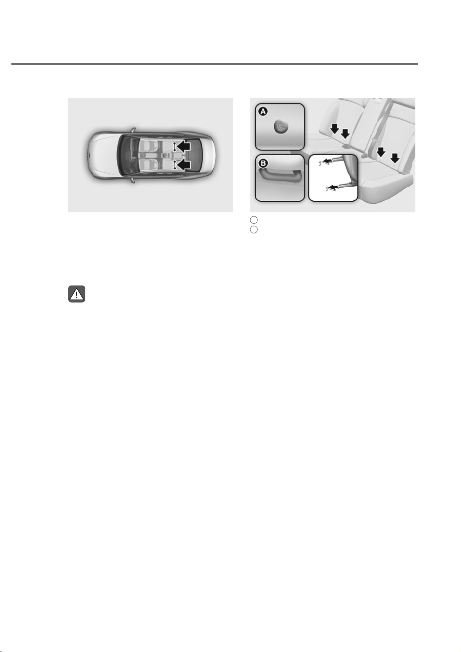
3-53
03
ORS031052
ORS031052
LATCH anchors have been provided in
the left and right outboard rear seating
positions. Their locations are shown
in the illustration. There are no LATCH
anchors provided for the center rear
seating position.
WARNING
Do not attempt to install a child
restraint system using LATCH anchors in
the rear center seating position. There
are no LATCH anchors provided for this
seat. Using the outboard seat anchors
can damage the anchors which may
break or fail in a collision resulting in
serious injury or death.
ORS031053
ORS031053
A
: Lower Anchorage Position Indicator,
B
: Lower Anchorage
The lower anchor position indicator
symbols are located on the left and right
rear seat backs to identify the position
of the lower anchors in your vehicle (see
arrows in illustration).
The LATCH anchors are located between
the seatback and the seat cushion of the
rear seat left and right outboard seating
positions.
Securing a child restraint with the
LATCH anchors system
To install a LATCH-compatible child
restraint in either of the rear outboard
seating positions:
1. Move the seat belt buckle away from
the lower anchors.
2. Move any other objects away from
the anchors that could prevent a
secure connection between the child
restraint and the lower anchors.
3. Place the child restraint on the vehicle
seat, then attach the seat to the lower
anchors according to the instructions
provided by the child restraint
manufacturer.
4. Follow the child restraint instructions
for properly adjusting and tightening
the lower attachments on the child
restraint to the lower anchors.

3-54
Safety System
WARNING
Take the following precautions when
using the LATCH system:
• Read and follow all installation
instructions provided with your child
restraint system.
• To prevent the child from reaching
and taking hold of unretracted
seat belts, buckle all unused rear
seat belts and retract the seat belt
webbing behind the child. Children
can be strangled if a shoulder belt
becomes wrapped around their neck
and the seat belt tightens.
• NEVER attach more than one
child restraint to a single anchor.
This could cause the anchor or
attachment to come loose or break.
• Always have the LATCH system
inspected by an authorized retailer
of Genesis Branded products after an
accident. An accident can damage
the LATCH system and may not
properly secure the child restraint.
NOTICE
The recommended weight for the
LATCH system is under 65 lb (30 kg).
How to determine an appropriate child
restraint weight:
Child weight + Child restraint weight <
65 lb (30kg)
Securing a child restraint seat with
“Tether Anchor” system
ORS032096N
ORS032096N
First secure the child restraint with
the LATCH lower anchors or the seat
belt. If the child restraint manufacturer
recommends that the top tether strap
be attached, attach and tighten the
top tether strap to the top tether strap
anchor.
Child restraint hook holders are located
on the rear of the seatbacks.
WARNING
Take the following precautions when
installing the tether strap:
• Read and follow all installation
instructions provided with your child
restraint system.
• NEVER attach more than one child
restraint to a single tether anchor.
This could cause the anchor or
attachment to come loose or break.
• Do not attach the tether strap to
anything other than the correct
tether anchor. It may not work
properly if attached to something
else.
• Do not use the tether anchors for
adult seat belts or harnesses, or for
attaching other items or equipment
to the vehicle.
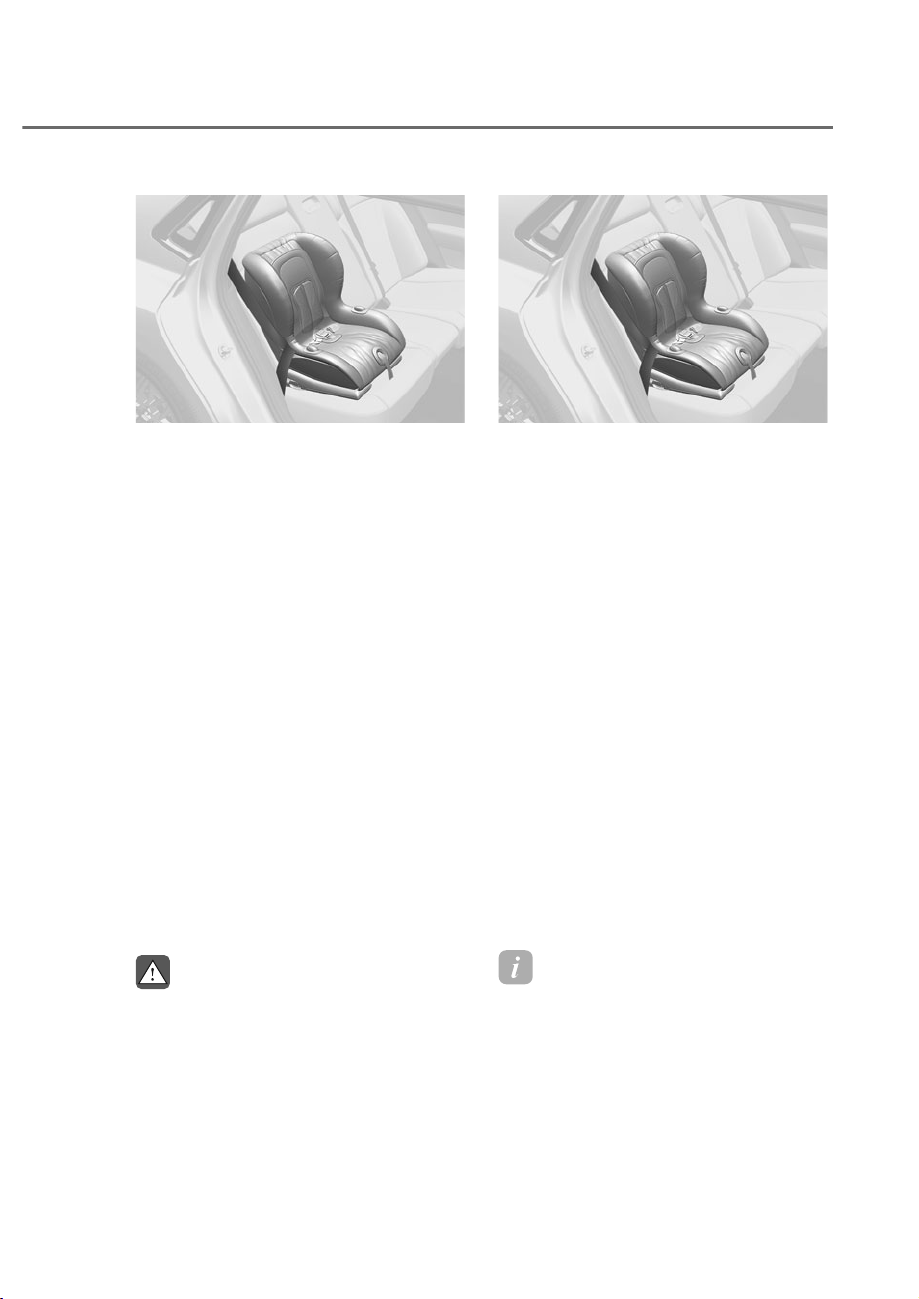
3-55
03
ORS031051
ORS031051
To install the tether anchor:
1. Route the child restraint tether strap
over the child restraint seatback.
Route the tether strap under the
head restraint and between the head
restraint posts, or route the tether
strap over the top of the vehicle
seatback. Make sure the strap is not
twisted.
2. Connect the tether strap hook to the
tether anchor, then tighten the tether
strap according to the child seat
manufacturer’s instructions to firmly
secure the child restraint to the seat.
3. Check that the child restraint is
securely attached to the seat by
pushing and pulling the seat forward-
and-back and side-to-side.
Securing a child restraint with lap/
shoulder belt
When not using the LATCH system, all
child restraints must be secured to a
vehicle rear seat with the lap part of a
lap/shoulder belt.
WARNING
ALWAYS place a rear-facing child
restraint in the rear seat of the vehicle.
Placing a rear-facing child restraint in
the front seat can result in serious injury
or death if the child restraint is struck
by an inflating air bag.
ORS031051
ORS031051
Automatic locking mode
Since all passenger seat belts move
freely under normal conditions and
only lock under extreme or emergency
conditions (emergency locking mode),
you must manually pull the seat belt all
the way out to shift the retractor to the
“Automatic Locking” mode to secure a
child restraint.
The “Automatic Locking” mode will
help prevent the normal movement of
the child in the vehicle from causing
the seat belt to loosen and compromise
the child restraint system. To secure a
child restraint system, use the following
procedure.
To install a child restraint system on the
rear seats, do the following:
1. Place the child restraint system on a
rear seat and route the lap/ shoulder
belt around or through the child
restraint, following the restraint
manufacturer’s instructions. Be sure
the seat belt webbing is not twisted.
Information
When using the rear center seat belt, you
should also refer to the “Rear Seat Belt –
Passenger’s 3-point system” section in this
chapter.
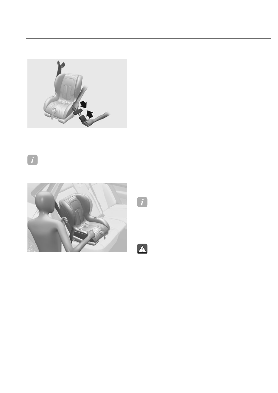
3-56
Safety System
ORS031122
ORS031122
2. Fasten the lap/shoulder belt latch
into the buckle. Listen for the distinct
“click” sound.
Information
Position the release button so that it is easy
to access in case of an emergency.
ORS031125
ORS031125
3. Pull the shoulder portion of the
seat belt all the way out. When the
shoulder portion of the seat belt
is fully extended, it will shift the
retractor to the “Automatic Locking”
(child restraint) mode.
4. Slowly allow the shoulder portion of
the seat belt to retract and listen for
an audible “clicking” or “ratcheting”
sound. This indicates that the retractor
is in the “Automatic Locking” mode.
If no distinct sound is heard, repeat
steps 3 and 4.
5. Remove as much slack from the belt
as possible by pushing down on the
child restraint system while feeding
the shoulder belt back into the
retractor.
6. Push and pull on the child restraint
system to confirm that the seat belt
is holding it firmly in place. If it is not,
release the seat belt and repeat steps
2 through 6.
7. Double check that the retractor is in
the “Automatic Locking” mode by
attempting to pull more of the seat
belt out of the retractor. If you cannot,
the retractor is in the “Automatic
Locking” mode.
If your CRS (child restraint system)
manufacturer instructs or recommends
you to use a tether anchor with the lap/
shoulder belt, refer to the previous pages
for more information.
Information
When the seat belt is allowed to retract to
its fully stowed position, the retractor will
automatically switch from the “Automatic
Locking” mode to the emergency lock
mode for normal adult usage.
WARNING
If the retractor is not in the “Automatic
Locking” mode, the child restraint
can move when your vehicle turns or
stops suddenly. A child can be seriously
injured or killed if the child restraint
is not properly anchored in the car,
including manually pulling the seat belt
all the way out to shift the retractor to
the “Automatic Locking” mode.
To remove the child restraint, press the
release button on the buckle and then
pull the lap/shoulder belt out of the
restraint and allow the seat belt to retract
fully.
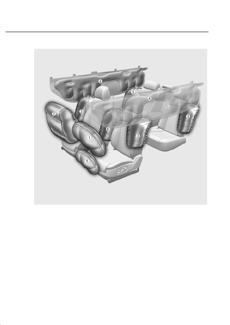
3-57
03
M Driver’s front air bag
N Passenger’s front air bag
O Side air bag
P Curtain air bag
Q Driver’s knee air bag
R Front center side air bag
$,5%$*ʏ6833/(0(17$/5(675$,176<67(0
The actual air bags in the vehicle may differ from the illustration.
ORS031003
ORS031003

3-58
Safety System
The vehicle is equipped with a
Supplemental Air Bag System for the
driver’s seat and front passenger’s seats.
The front air bags are designed to
supplement the three-point seat belts.
For these air bags to provide protection,
the seat belts must be worn at all times
when driving.
You can be severely injured or killed
in an accident if you are not wearing
a seat belt. Air bags are designed to
supplement seat belts, but do not
replace them. Also, air bags are not
designed to deploy in every collision. In
some accidents, the seat belts are the
only restraint protecting you.
WARNING
AIR BAG SAFETY PRECAUTIONS
ALWAYS use seat belts and Child
Restraint Systems - every trip, every
time, everyone! Even with air bags, you
can be seriously injured or killed in a
collision if you are improperly belted or
not wearing your seat belt when the air
bag inflates.
NEVER place a child in any Child
Restraint System or booster seat in the
front passenger seat, unless the air bag
is deactivated.
An inflating air bag could forcefully
strike the infant or child causing serious
or fatal injuries.
ABC - Always Buckle Children under age
13 in the back seat. It is the safest place
for children of any age to ride. If a child
age 13 or older must be seated in the
front seat, he or she must be properly
belted and the seat should be moved as
far back as possible.
All occupants should sit upright with
the seatback in an upright position,
centered on the seat cushion with
their seat belt on, legs comfortably
extended and their feet on the floor
until the vehicle is parked and the
vehicle is turned off. If an occupant is
out of position during an accident, the
rapidly deploying air bag may forcefully
contact the occupant causing serious or
fatal injuries.
You and your passengers should never
sit or lean unnecessarily close to the air
bags or lean against the door or center
console.
Move your seat as far back as possible
from front air bags, while still
maintaining control of the vehicle.
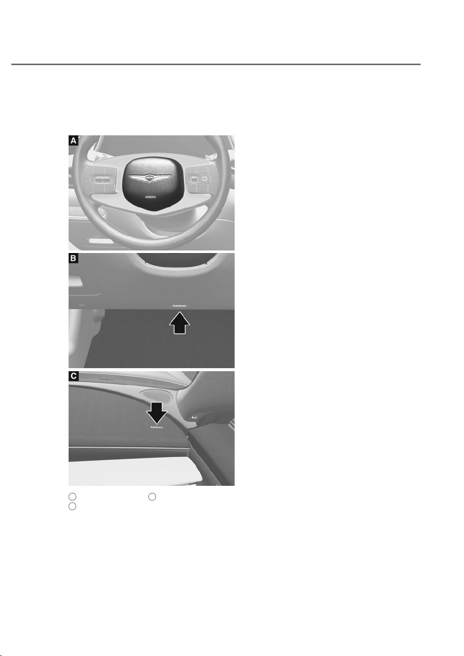
3-59
03
Where are the Air Bags?
Driver’s and passenger’s front air
bags
ORS031055
ORS031055
ORS031056
ORS031056
ORS031057L
ORS031057L
A
: Driver’s front air bag,
B
: Driver’s knee air bag,
C
: Passenger’s front air bag
Your vehicle is equipped with a
Supplemental Restraint System (SRS)
and lap/shoulder belts at both the driver
and passenger seating positions.
The SRS consists of air bags which are
located in the center of the steering
wheel, in the driver’s side lower crash
pad below the steering wheel, and the
passenger’s side front panel pad above
the glove box.
The air bags are labeled with the letters
“AIR BAG” embossed on the pad covers.
The purpose of the SRS is to provide the
vehicle’s driver and front passengers with
additional protection than that offered
by the seat belt system alone in case of a
frontal impact of sufficient severity.
The SRS uses sensors to gather
information about the driver’s and front
passenger's seat belt usage and impact
severity.
The seat belt buckle sensors determine
if the driver and front passenger's seat
belts are fastened. These sensors provide
the ability to control the SRS deployment
based on whether or not the seat belts
are fastened, and how severe the impact
is.
The SRS offers the ability to control the
airbag inflation within two levels. A first
stage level is provided for moderate-
severity impacts. A second stage level is
provided for more severe impacts.
According to the impact severity and
seat belt usage, the SRS Control Module
(SRSCM) controls the air bag inflation.
Failure to properly wear seat belts may
increase the risk or severity of injury in a
collision.

3-60
Safety System
WARNING
To reduce the risk of serious injury or
death from inflating front air bags, take
the following precautions:
• Seat belts must be worn at all times
to help keep occupants positioned
properly.
• Move your seat as far back as
possible from front air bags, while
still maintaining control of the
vehicle.
• Never lean against the door or center
console.
• Do not allow the front passenger
to place their feet or legs on the
dashboard.
• No objects (such as crash pad
cover, mobile phone holder, cup
holder, perfume or stickers) should
be placed over or near the air bag
modules on the steering wheel,
instrument panel, windshield glass,
and the front passenger’s panel
above the glove box. Such objects
could cause harm if the vehicle is in a
crash severe enough to cause the air
bags to deploy.
• Do not attach any objects on the
front windshield and inside mirror.
Side air bags and front center side
air (if equipped)
ORS031064
ORS031064
ORS031065
ORS031065
ORS031075
ORS031075
A
: Side air bag (Front row),
B
: Side air bag (Second row),
C
: Front center side air bag (Driver’s seat)

3-61
03
Your vehicle is equipped with a side air
bag in each front and outboard second
row seat. Additionally, a front center
side air bag is provided in the inboard
side of the driver seatback. The purpose
of the air bag is to provide the vehicle’s
additional protection than that offered by
the seat belt alone.
The side air bags and front center side
air bag are designed to deploy during
certain side impact collisions, depending
on the crash severity.
For vehicles equipped with a rollover
sensor the front center side air bag,
side and/or curtain air bags and pre-
tensioners on both sides of the vehicle
may deploy if a rollover or possible
rollover is detected.
The side air bags and front center side air
bag are not designed to deploy in all side
impact or rollover situations.
WARNING
To reduce the risk of serious injury or
death from an inflating side air bag
and front center side air bag, take the
following precautions:
• Seat belts must be worn at all times
to help keep occupants positioned
properly.
• Do not allow passengers to lean their
heads or bodies onto doors, put their
arms on the doors, stretch their arms
out of the window, or place objects
between the doors and seats.
• Hold the steering wheel at the 9
o’clock and 3 o’clock positions, to
minimize the risk of injuries to your
hands and arms.
• Do not use any accessory seat
covers. This could reduce or prevent
the effectiveness of the system.
• Do not hang other objects except
clothes. In an accident it may cause
vehicle damage or personal injury
especially when air bag is inflated.
• Do not place any objects over the
air bag or between the air bag and
yourself. Also, do not attach any
objects around the area the air bag
inflates such as the door, side door
glass, front and rear pillar.
• Do not place any objects between
the door and the seat. They may
become dangerous projectiles if the
side air bag inflates.
• Do not install any accessories on the
side or near the side air bags.
• Do not cause impact to the doors
when the Engine Start/Stop button
is in the ON or START position as this
may cause the side air bags to inflate.
• If the seat or seat cover is damaged,
have the system serviced by an
authorized retailer of Genesis
Branded products.
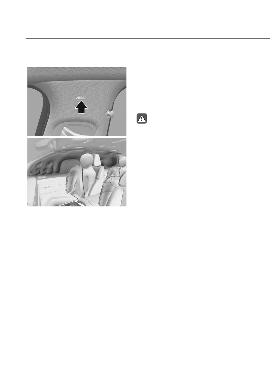
3-62
Safety System
Curtain air bags
ORS031066
ORS031066
ORS031076
ORS031076
Curtain air bags are located along both
sides of the roof rails above the front and
rear doors.
They are designed to help protect the
heads of the front seat occupants and
the rear outboard seat occupants in
certain side impact collisions.
The curtain air bags are designed to
deploy during certain side impact
collisions, depending on the crash
severity.
For vehicles equipped with a rollover
sensor the side and/or curtain air bags
and pre-tensioners on both sides of
the vehicle may deploy if a rollover or
possible rollover is detected.
The curtain air bags are not designed
to deploy in all side impact or rollover
situations.
WARNING
To reduce the risk of serious injury or
death from an inflating curtain air bag,
take the following precautions:
• All seat occupants must wear
seat belts at all times to help keep
occupants positioned properly.
• Properly secure Child Restraint
System as far away from the door as
possible.
• Do not place any objects over the air
bag. Also, do not attach any objects
around the area the air bag inflates
such as the door, side door glass,
front and rear pillar, roof side rail.
• Do not hang other objects except
clothes, especially hard or breakable
objects.
In an accident, it may cause vehicle
damage or personal injury.
• Do not allow passengers to lean their
heads or bodies onto doors, put their
arms on the doors, stretch their arms
out of the window, or place objects
between the doors and seats.
• Do not attempt to open or repair
the side curtain air bags yourself.
If necessary, have the air back be
inspected by an authorized retailer of
Genesis Branded products.

3-63
03
How Does the Air Bags System
Operate?
ORS032054N
ORS032054N
The SRS consists of the following
components:
M Driver’s front air bag module
N Passenger’s front air bag module
O Front center side air bag module
P Side air bag modules
Q Curtain air bag modules
R Front retractor pre-tensioner
S Air bag warning light
T
SRS control module (SRSCM) /
Rollover sensor
U Front impact sensors
V Side impact sensors
Side pressure sensors
Driver’s knee air bag module
Driver’s and front passenger’s seat belt
buckle sensors
Rear retractor pre-tensioner (if
equipped)
Occupant classification system
The SRSCM (Supplemental Restraint
System Control Module) continually
monitors all SRS components while
the Engine Start/Stop button is ON to
determine if a crash impact is severe
enough to require air bag deployment or
pre-tensioner seat belt deployment.
SRS warning light
The SRS (Supplemental Restraint System)
air bag warning light on the instrument
panel displays the air bag symbol
depicted in the illustration. The system
checks the air bag electrical system for
malfunctions. The light indicates that
there is a potential problem with your air
bag system, which could include your
side and/or curtain air bags used for
rollover protection.

3-64
Safety System
WARNING
If your SRS malfunctions, the air bag
may not inflate properly during an
accident, increasing the risk of serious
injury or death.
If any of the following conditions occur,
your SRS is malfunctioning:
• The light does not turn on for
approximately three to six seconds
when the Engine Start/Stop button is
in the ON position.
• The light stays on after illuminating
for approximately three to six
seconds.
• The light comes on while the vehicle
is in motion.
• The light blinks when the engine is
running.
Have an authorized retailer of Genesis
Branded products inspect the SRS
as soon as possible if any of these
conditions occur.
During a moderate to severe frontal
collision, sensors will detect the
vehicle’s rapid deceleration. If the rate of
deceleration is high enough, the control
unit will inflate the front air bags, at the
time and with the force needed.
The front air bags help protect the driver
and front passenger by responding to
frontal impacts in which seat belts alone
cannot provide adequate restraint. When
needed, the side air bags help provide
protection in the event of a side impact
or rollover by supporting the side upper
body area.
• Air bags are activated (able to inflate
if necessary) only when the Engine
Start/Stop button is in the ON or
START position and it can be activated
within about 3 minutes after the
engine is turned off.
• Air bags inflate in the event of certain
frontal or side collisions to help
protect the occupants from serious
physical injury.
• There is no single speed at which the
air bags will inflate. Generally, air bags
are designed to inflate based upon the
severity of a collision and its direction.
These two factors determine whether
the sensors produce an electronic
deployment/inflation signal.
• The front air bags will completely
inflate and deflate in an instant. It is
virtually impossible for you to see the
air bags inflate during an accident. It is
much more likely that you will simply
see the deflated air bags hanging out
of their storage compartments after
the collision.
• In addition to inflating in serious side
collisions, vehicles equipped with a
rollover sensor, side and/or curtain air
bags and front center side air bag will
inflate if the sensing system detects a
rollover.
When a rollover is detected, curtain
air bags will remain inflated longer to
help provide protection from ejection,
especially when used in conjunction
with the seat belts.
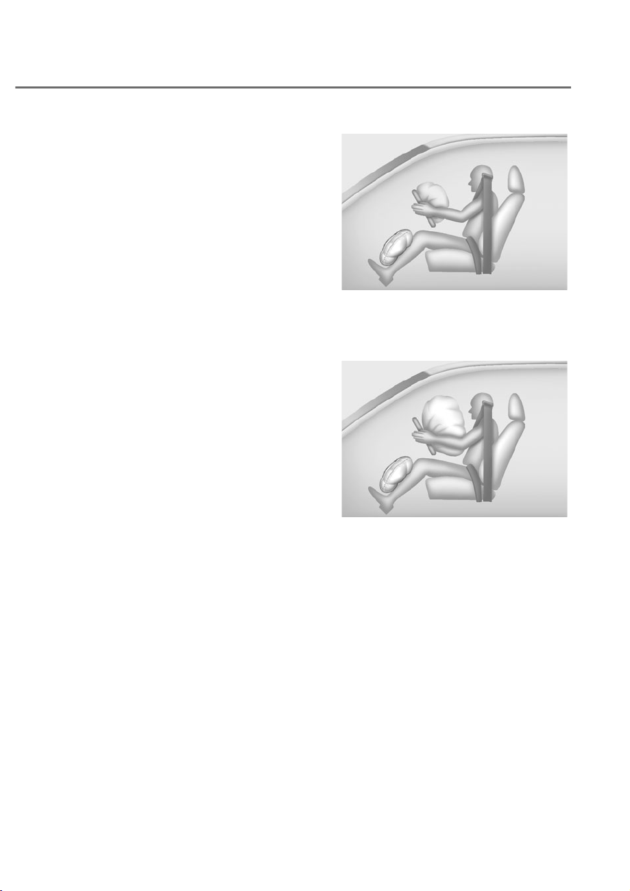
3-65
03
• To help provide protection, the air
bags must inflate rapidly. The speed
of air bag inflation is a consequence
of extremely short time in which
to inflate the air bag between the
occupant and the vehicle structures
before the occupant impacts those
structures. This speed of inflation
reduces the risk of serious or life-
threatening injuries and is thus a
necessary part of air bag design.
However, the rapid air bag inflation
can also cause injuries which can
include facial abrasions, bruises and
broken bones because the inflation
speed also causes the air bags to
expand with a great deal of force.
• There are even circumstances under
which contact with the air bag can
cause fatal injuries, especially if the
occupant is positioned excessively
close to the air bag.
You can take steps to reduce the risk of
being injured by an inflating air bag. The
greatest risk is sitting too close to the air
bag. An air bag needs space to inflate.
It is recommended that drivers sit as far
as possible between the center of the
steering wheel and the chest while still
maintaining control of the vehicle.
Driver’s front air bag (1)
Driver’s front air bag (1)
OHI038171L
OHI038171L
When the SRSCM detects a sufficiently
severe impact to the front of the vehicle,
it will automatically deploy the front air
bags.
Driver’s front air bag (2)
Driver’s front air bag (2)
OHI038172L
OHI038172L
Upon deployment, tear seams molded
directly into the pad covers will separate
under pressure from the expansion of the
air bags. Further opening of the covers
allows full inflation of the air bags.
A fully inflated air bag, in combination
with a properly worn seat belt, slows the
driver’s or the front passenger’s forward
motion, reducing the risk of head and
chest injury.
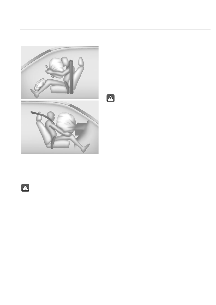
3-66
Safety System
Driver’s front air bag (3)
Driver’s front air bag (3)
OHI038173L
OHI038173L
Passenger’s front air bag
Passenger’s front air bag
ODN8039080L
ODN8039080L
After complete inflation, the air bag
immediately starts deflating, enabling
the driver to maintain forward visibility
and the ability to steer or operate other
controls.
WARNING
To prevent objects from becoming
dangerous projectiles when the
passenger’s air bag inflates:
• Do not install or place any objects
(drink holder, CD holder, stickers,
etc.) on the front passenger’s panel
above the glove box where the
passenger’s air bag is located.
• Do not install a container of liquid
air freshener near the instrument
cluster or on the instrument panel
surface.
What to Expect After an Air Bag
Inflates
After a frontal or side air bag inflates, it
will deflate very quickly. Air bag inflation
will not prevent the driver from seeing
out of the windshield or being able
to steer. Curtain air bags may remain
partially inflated for some time after they
deploy.
WARNING
After an air bag inflates, take the
following precautions:
• Open your windows and doors as
soon as possible after impact to
reduce prolonged exposure to the
smoke and powder released by the
inflating air bag.
• Do not touch the air bag storage
area’s internal components
immediately after an air bag has
inflated. The parts that come into
contact with an inflating air bag may
be very hot.
• Always wash exposed skin areas
thoroughly with cold water and mild
soap.
• Have an authorized retailer of
Genesis Branded products replace
the air bag immediately after
deployment. Air bags are designed to
be used only once.
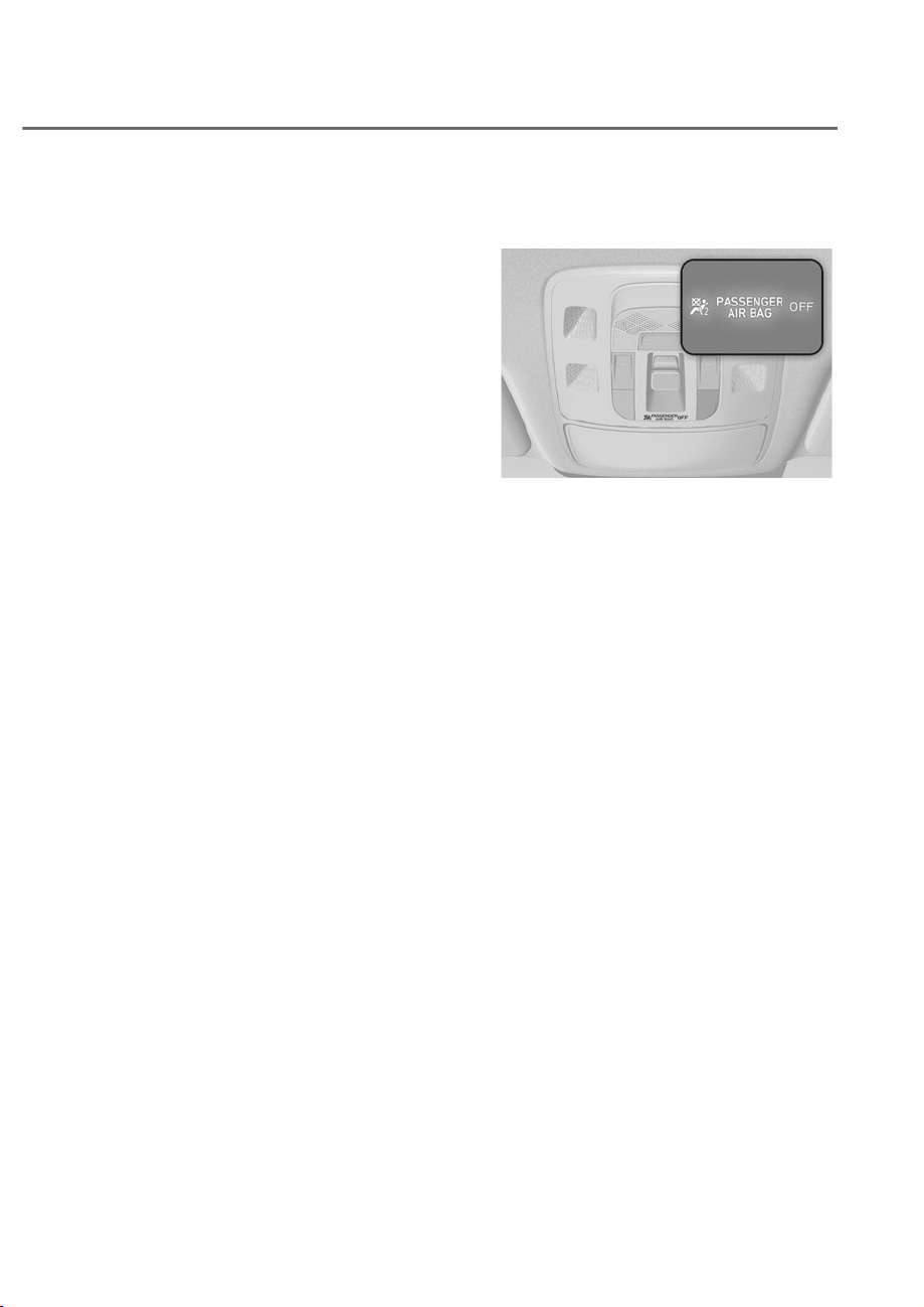
3-67
03
Noise and smoke from inflating air
bag
When the air bags inflate, they make a
loud noise and may produce smoke and
powder in the air inside of the vehicle.
This is normal and is a result of the
ignition of the air bag inflator. After the
air bag inflates, you may feel substantial
discomfort in breathing because of the
contact of your chest with both the seat
belt and the air bag, as well as from
breathing the smoke and powder. The
powder may aggravate asthma for some
people. If you experience breathing
problems after an air bag deployment,
seek medical attention immediately.
Though the smoke and powder are
nontoxic, they may cause irritation to
the skin, eyes, nose, throat, etc. If this is
the case, wash and rinse with cold water
immediately and seek medical attention
if the symptoms persist.
Occupant Classification System
(OCS)
ORS032059N
ORS032059N
Your vehicle is equipped with an
Occupant Classification System (OCS) in
the front passenger’s seat.
Main components of the Occupant
Classification System
• A detection device located within the
front passenger seat cushion.
• Electronic system to determine
whether the passenger air bag
systems should be activated or
deactivated.
• An indicator light located on the
overhead console which illuminates
the words “PASSENGER AIR BAG OFF”
indicating the front passenger air bag
system is deactivated.
• The overhead console air bag
indicator light is interconnected with
the OCS.
The OCS is designed to help detect
the presence of a properly-seated
front passenger and determine if the
passenger’s front air bag should be
enabled (may inflate) or not.
The purpose is to help reduce the risk
of injury or death from an inflating air
bag to certain front passenger seat
occupants, such as children, by requiring
the air bag to be automatically turned
OFF.

3-68
Safety System
For example, if a child restraint of the
type specified in the regulations is on the
seat, the occupant classification sensor
can detect it and cause the air bag to
turn OFF.
Front passenger seat adult occupants
who are properly seated and wearing the
seat belt properly, should not cause the
passenger air bag to be automatically
turned OFF. For smaller adults it may turn
off. However, if the occupant does not
sit in the seat properly (for example, by
not sitting upright, by sitting on the edge
of the seat, or by otherwise being out of
position), this could cause the sensor to
turn the air bag OFF.
You will find the “PASSENGER AIR BAG
OFF” indicator overhead console panel.
This system detects the conditions 1-4
in the following table and activates or
deactivates the front passenger air bag
based on these conditions.
Always be sure that you and all vehicle
occupants are seated properly and
wearing the seat belt properly for the
most effective protection by the air bag
and the seat belt.
The OCS may not function properly if the
passenger takes actions which can affect
the classification system. These include:
• Failing to sit in an upright position.
• Leaning against the door or center
console.
• Sitting towards the sides of the front
of the seat.
• Putting their legs on the dashboard or
resting them on other locations which
reduce the passenger weight on the
front seat.
• Wearing the seat belt improperly.
• Reclining the seatback.
• Wearing a thick clothes like ski wear
or hip protection wear.
• Putting an additional thick cushion on
the seat.
• Putting electrical devices (for
example, notebook, satellite radio) on
the seat with inverter charging.

3-69
03
Condition and operation in the front passenger Occupant Classification System
Condition detected by the
occupant classification system
Indicator/Warning light Devices
“PASSENGER
AIR BAG OFF”
indicator light
SRS warning
light
Front passenger
air bag
1. Adult
*1
Off Off Activated
2. Infant
*2
or child restraint
system with 12 months old
*3 *4
On Off Deactivated
3. Unoccupied
On Off Deactivated
4. Malfunction in the system
Off On Activated
*1 :
The system judges a person of adult size as an adult. When a smaller adult sits in the
front passenger seat, the system may recognize him/her as a child depending on his/her
physique and posture.
*2 :
Do not allow children to ride in the front passenger seat. When a larger child who has
outgrown a child restraint system sits in the front passenger seat, the system may
recognize him/her as an adult depending upon his/her physique or sitting position.
*3 :
Never install a child restraint system on the front passenger seat.
*4 :
The PASSENGER AIR BAG “OFF” indicator may turn on or off when a child above 12
months to 12 years old (with or without child restraint system) sits in the front passenger
seat. This is a normal condition.
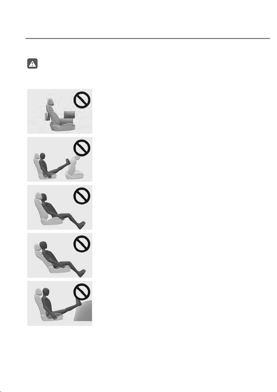
3-70
Safety System
WARNING
Riding in an improper position or placing weight on the front passenger’s seat when
it is unoccupied by a passenger adversely affects the OCS. To reduce the risk of
serious injury or death:
ORS031132
ORS031132
• NEVER put a heavy load in the front seat or seatback
pocket, or hang any items on the front passenger
seat.
ORS032120N
ORS032120N
• NEVER place your feet on the front passenger
seatback.
ORS031119
ORS031119
• NEVER sit with your hips shifted towards the front of
the seat.
ORS031116
ORS031116
• NEVER ride with the seatback reclined when the
vehicle is moving.
ORS031120
ORS031120
• NEVER place your feet or legs on the dashboard.
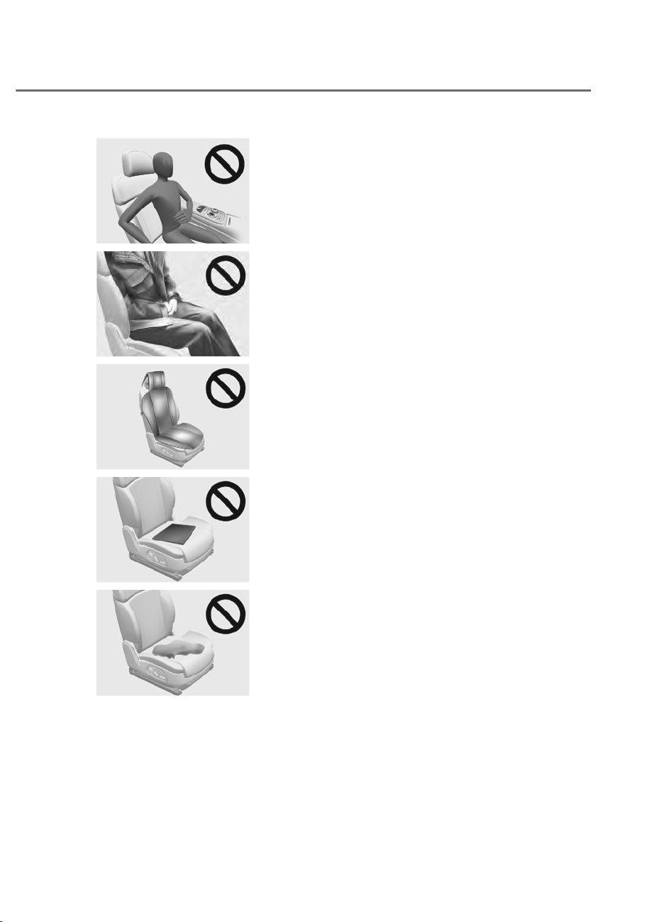
3-71
03
ORS031117
ORS031117
• NEVER lean on the door or center console or sit on
one side of the front passenger seat.
ORS031060
ORS031060
• Do not sit on the passenger seat wearing heavily
padded clothes such as ski wear and hip protector.
ORS031062
ORS031062
• Do not use car seat accessories such as thick blankets
and cushions which cover up the car seat surface.
ORS031061
ORS031061
• Do not place electronic devices such as laptops, DVD
player, or conductive materials such as water bottles
on the passenger seat.
• Do not use electronic devices such as laptops and
satellite radios which use inverter chargers.
ORS031063
ORS031063
• If large quantity of liquid has been spilled on the
passenger seat, the air bag warning light may
illuminate or malfunction.
Therefore, make sure the seat has been completely
dried before driving the vehicle.
• Do not place sharp objects on the front passenger seat. These may damage the
occupant detection system, if they puncture the seat cushion.
• Do not place any items under the front passenger seat.
• When replacing the seat, use original Genesis parts only. The OCS has been
developed based on using original Genesis parts car seats only. Altering or
changing the authentic parts may result in system malfunction and increase
risk of injury when in collision. Any of the above could interfere with the proper
operation of the OCS sensor thereby increasing the risk of an injury in an
accident.
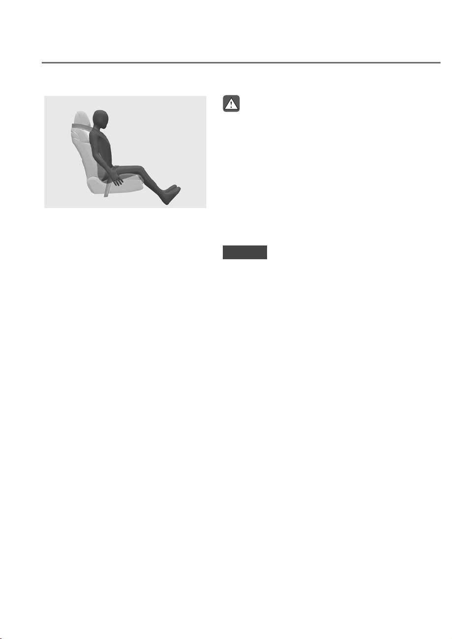
3-72
Safety System
ORS031121
ORS031121
Proper seated position for OCS
If the “PASSENGER AIR BAG OFF”
indicator is on when an adult is seated
in the front passenger seat, place the
Engine Start/Stop button in the OFF
position and ask the passenger to sit
properly (sitting upright with the seat
back in an upright position, centered
on the seat cushion with their seat belt
on, legs comfortably extended and their
feet on the floor). Restart the engine and
have the person remain in t hat position.
This will allow the system to detect the
person and to enable the passenger air
bag. If the “PASSENGER AIR BAG OFF”
indicator is still on, ask the passenger to
move to the rear seat.
WARNING
NEVER allow an adult passenger to ride
in the front passenger seat when the
“PASSENGER AIR BAG OFF” indicator
is illuminated. During a collision, the
air bag will not inflate if the indicator
is illuminated. Have your passenger
reposition themselves in the seat. If the
“PASSENGER AIR BAG OFF” indicator
remains illuminated after the passenger
repositions themselves properly
and the vehicle is restarted, have
the passenger move to the rear seat
because the air bag will not inflate.
NOTICE
The “PASSENGER AIR BAG OFF”
indicator generally illuminates for
approximately 4 seconds after the
Engine Start/Stop button is in the ON
position or after the engine is started.
But, if the ignition switch or ENGING
START/STOP button is turned to the ON
position within 3 minutes after ignition
OFF, the indicator does not illuminate.
If the front passenger seat is occupied,
the OCS will then classify the front
passenger after several more seconds.
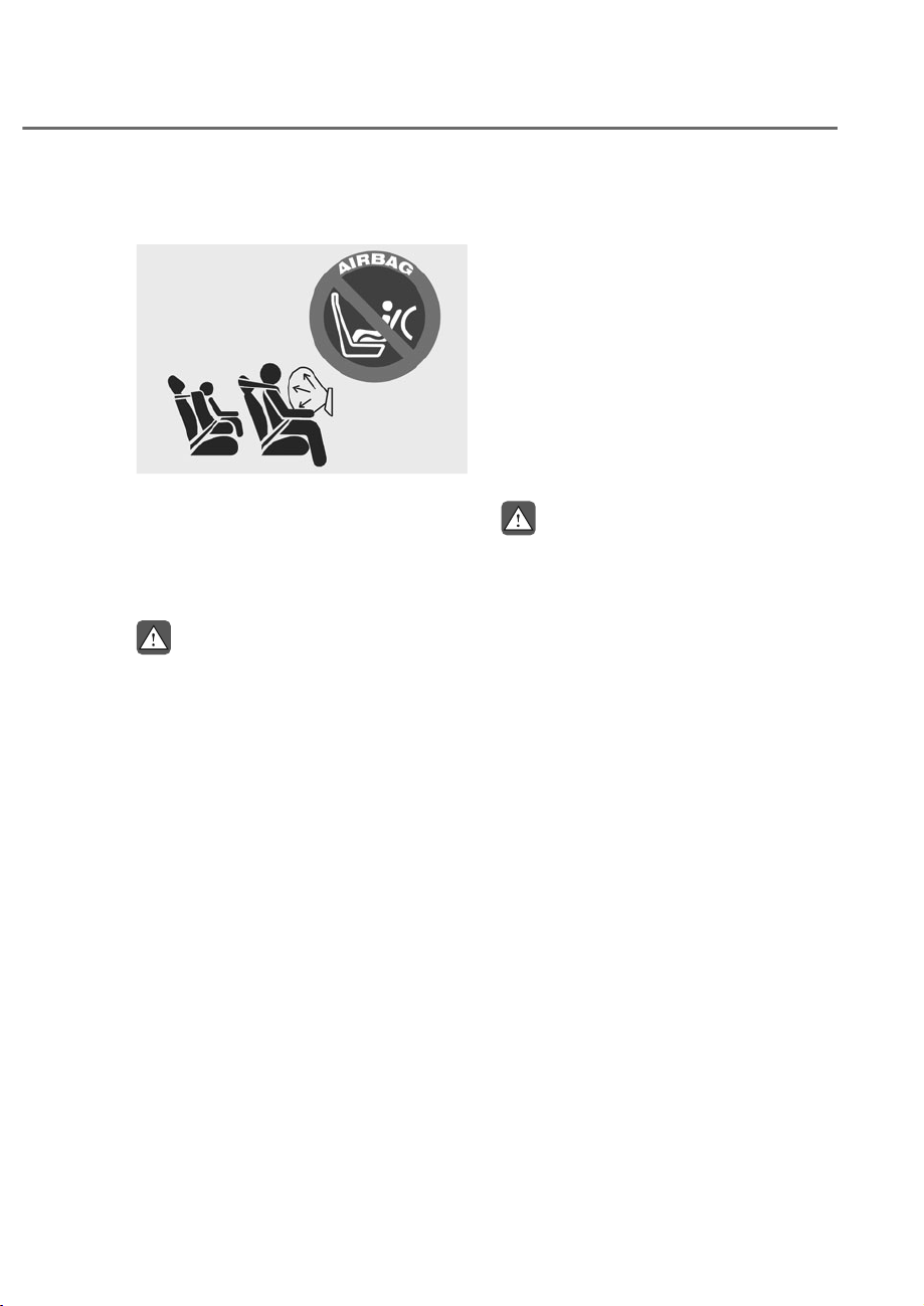
3-73
03
Do Not Install a Child Restraint in the
Front Passenger’s Seat
OHI039193N
OHI039193N
Even though your vehicle is equipped
with the OCS, never install a child
restraint in the front passenger’s seat.
An inflating air bag can forcefully strike a
child or child restraint resulting in serious
or fatal injury.
WARNING
• NEVER place a rear-facing or front-
facing child restraint in the front
passenger’s seat of the vehicle.
• An inflating frontal air bag could
forcefully strike a child resulting in
serious injury or death.
• Always properly restrain children in
an appropriate child restraint in the
rear seat of the vehicle.
Why Didn’t My Air Bag Go Off In
a Collision?
There are certain types of accidents in
which the air bag would not be expected
to provide additional protection. These
include rear impacts, second or third
collisions in multiple impact accidents,
as well as low speed impacts. Damage to
the vehicle indicates a collision energy
absorption, and is not an indicator of
whether or not an air bag should have
inflated.
Air bag collision sensors
WARNING
To reduce the risk of an air bag
deploying unexpectedly and causing
serious injury or death:
• Do not hit or allow any objects to
impact the locations where air bags
or sensors are installed.
• Do not perform maintenance on or
around the air bag sensors. If the
location or angle of the sensors is
altered, the air bags may deploy
when they should not or may not
deploy when they should.
• Do not install bumper guards or
replace the bumper with a non-
genuine Genesis part. This may
adversely affect the collision and air
bag deployment performance.
• Press the Engine Start/Stop button to
the OFF or ACC position and wait for
3 minutes, when the vehicle is being
towed to prevent inadvertent air bag
deployment.
• Have all air bag repairs performed
by an authorized retailer of Genesis
Branded products.
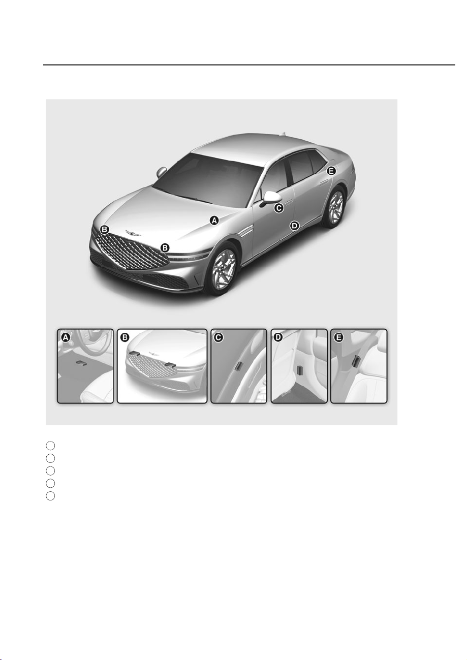
3-74
Safety System
ORS031067L
ORS031067L
A
SRS control module/Rollover sensor
B
Front impact sensor
C
Side impact sensor (Pressure): Front door
D
Side impact sensor (Acceleration): B-Pillar
E
Side impact sensor (Acceleration): C-Pillar
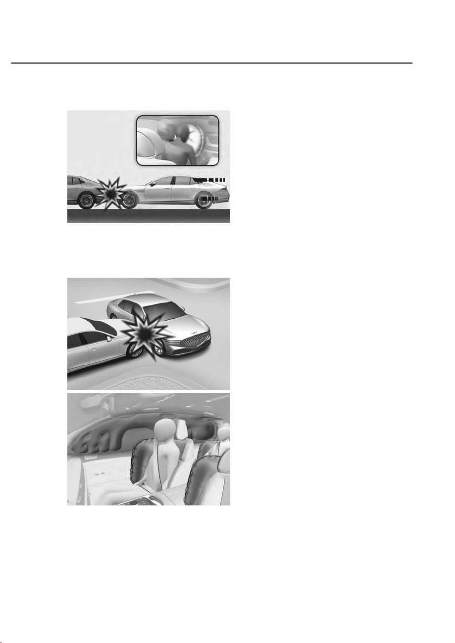
3-75
03
Air bag inflation conditions
ORS031073
ORS031073
Front air bags
Front air bags are designed to inflate
in a frontal collision depending on the
severity of impact of the front collision.
ORS031074L
ORS031074L
ORS031077
ORS031077
Side and curtain air bags and front center
side air bag
Side and curtain air bags and the front
center side air bag are designed to
inflate when an impact is detected by
side collision sensors depending on the
severity of impact resulting from a side
impact collision.
Although the driver’s and front
passenger’s air bags are designed to
inflate in frontal collisions, they also may
inflate in other types of collisions if the
front impact sensors detect a sufficient
impact. Side and curtain air bags and the
front center side air bag are designed
to inflate in side impact collisions, but
they may inflate in other collisions if the
side impact sensors detect a sufficient
impact.
Also, the side and curtain air bags and
the front center side air bag are designed
to inflate when a rollover is detected by a
rollover sensor.
If the vehicle chassis is impacted by
bumps or objects on unimproved roads,
the air bags may deploy. Drive carefully
on unimproved roads or on surfaces not
designed for vehicle traffic to prevent
unintended air bag deployment.
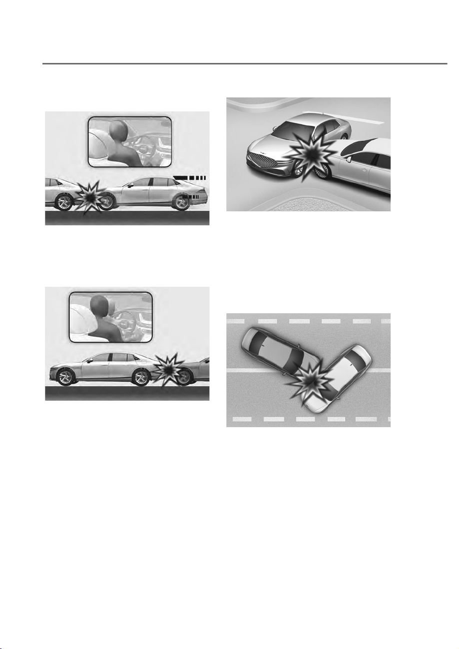
3-76
Safety System
Air bag non-inflation conditions
ORS031078L
ORS031078L
In certain low-speed collisions the air
bags may not deploy. The air bags are
designed not to deploy in such cases
because they may not provide benefits
beyond the protection of the seat belts.
ORS031079L
ORS031079L
Front air bags are not designed to inflate
in rear collisions, because occupants
are moved backward by the force of the
impact. In this case, inflated air bags
would not provide any additional benefit.
ORS031080L
ORS031080L
Front air bags may not inflate in side
impact collisions, because occupants
move in the direction of the collision,
and thus in side impacts, front air bag
deployment would not provide additional
occupant protection.
However, side and curtain air bags and
the front center side air bag may inflate
depending on the severity of impact.
ORS031081
ORS031081
In an angled collision, the force of impact
may direct the occupants in a direction
where the air bags would not be able to
provide any additional benefit, and thus
the sensors may not deploy any air bags.
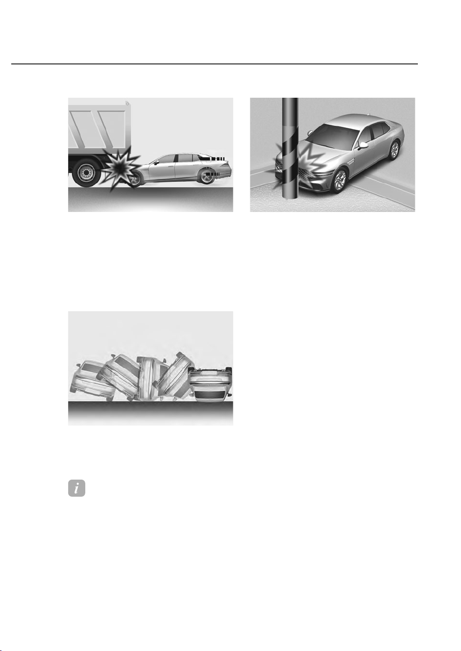
3-77
03
ORS031082L
ORS031082L
Just before impact, drivers often brake
heavily. Such heavy braking lowers the
front portion of the vehicle causing it
to “ride” under a vehicle with a higher
ground clearance. Air bags may not
inflate in this “underride” situation
because deceleration forces that are
detected by sensors may be significantly
reduced by such “underride” collisions.
ORS031083
ORS031083
Front air bags may not inflate in
rollover accidents because front air bag
deployment would not provide additional
occupant protection.
Information
With rollover sensor
The side and curtain air bags and the
front center side air bag may inflate in a
rollover situation, when it is detected by
the rollover sensor.
ORS031084L
ORS031084L
Air bags may not inflate if the vehicle
collides with objects such as utility poles
or trees, where the point of impact is
concentrated and the collision energy is
absorbed by the vehicle structure.

3-78
Safety System
SRS Care
The SRS is virtually maintenance-free
and there are no parts you can safely
service by yourself. If the SRS air bag
warning light does not illuminate when
the Engine Start/Stop button is in the
ON position, or continuously remains on,
have the system immediately inspected
by an authorized retailer of Genesis
Branded products.
Any work on the SRS system, such as
removing, installing, repairing, or any
work on the steering wheel, the front
passenger’s panel, front seats and roof
rails be performed by an authorized
retailer of Genesis Branded products.
Improper handling of the SRS system
may result in serious personal injury.
WARNING
To reduce the risk of serious injury or
death take the following precautions:
• Do not attempt to modify or
disconnect the SRS components or
wiring, including the addition of any
kind of badges to the pad covers or
modifications to the body structure.
• Do not place objects over or near
the air bag modules on the steering
wheel, instrument panel, and the
front passenger’s panel above the
glove box.
• Clean the air bag pad covers with
a soft cloth moistened with plain
water. Solvents or cleaners could
adversely affect the air bag covers
and proper deployment of the
system.
• Always have inflated air bags
replaced by an authorized retailer of
Genesis Branded products.
• If components of the air bag system
must be discarded, or if the vehicle
must be scrapped, certain safety
precautions must be observed.
Consult an authorized retailer of
Genesis Branded products for the
necessary information. Failure to
follow these precautions could
increase the risk of personal injury.
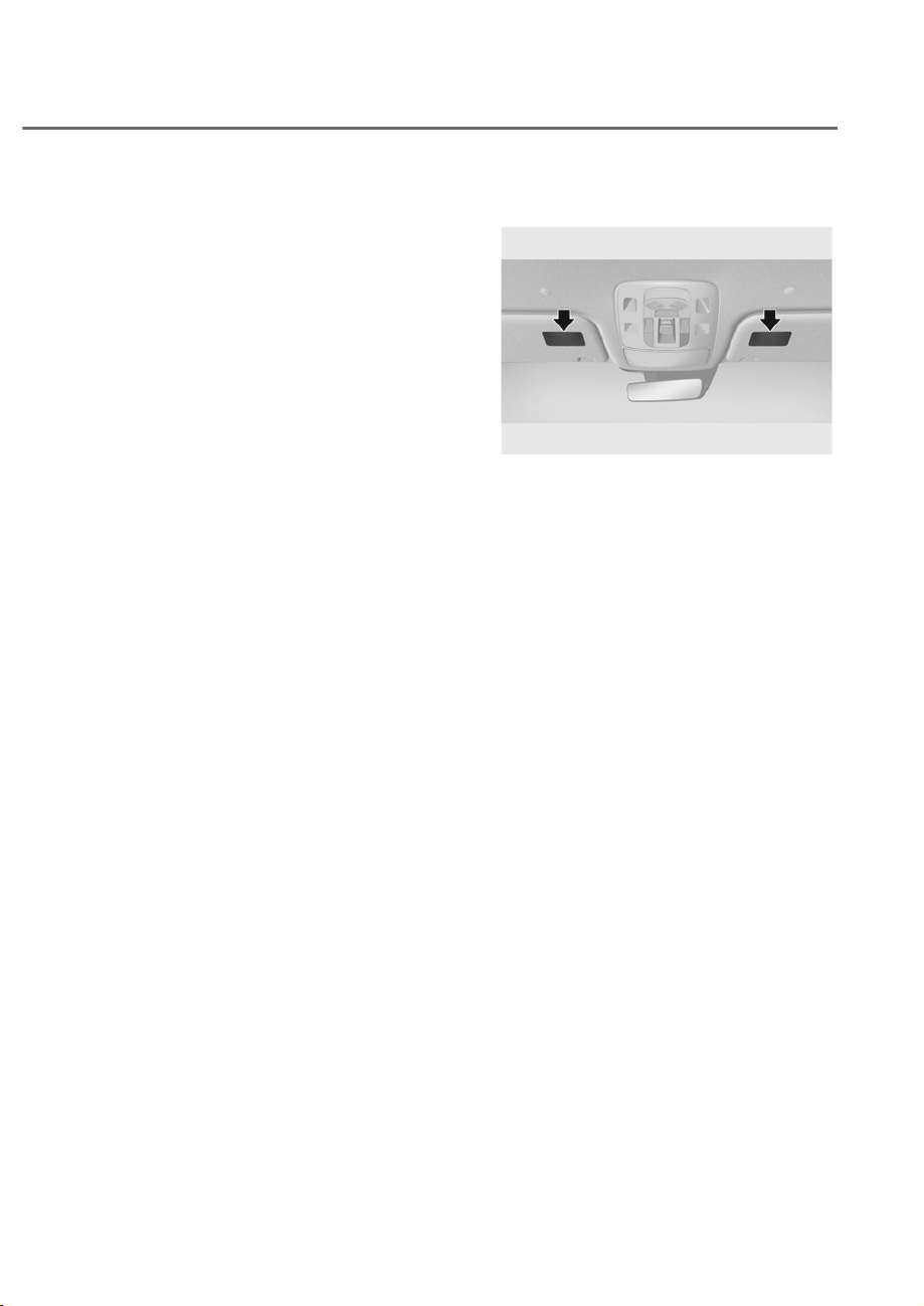
3-79
03
Additional Safety Precautions
Passengers should not move out of
or change seats while the vehicle is
moving. A passenger who is not wearing
a seat belt during a crash or emergency
stop can be thrown against the inside of
the vehicle, against other occupants, or
be ejected from the vehicle.
Do not use any accessories on seat
belts. Devices claiming to improve
occupant comfort or reposition the seat
belt can reduce the protection provided
by the seat belt and increase the chance
of serious injury in a crash.
Do not modify the front seats.
Modification of the front seats could
interfere with the operation of the
supplemental restraint system sensing
components or side air bags.
Do not place items under the front
seats. Placing items under the front seats
could interfere with the operation of the
supplemental restraint system sensing
components and wiring harnesses.
Do not cause impact to the doors.
Impact to the doors when the Engine
Start/Stop button is in the ON or START
position may cause the air bags to
inflate.
Modifications to accommodate
disabilities. If you require modification
to your vehicle to accommodate a
disability, contact Genesis Customer
Care at 844 340-9741
Adding equipment to or modifying
your air bag equipped vehicle
If you modify your vehicle by changing
your vehicle’s frame, bumper system,
front end or side sheet metal or ride
height, this may affect the operation of
your vehicle’s air bag system.
Air Bag Warning Labels
ORS032085N
ORS032085N
Air bag warning labels, required by the
U.S. National Highway Traffic Safety
Administration (NHTSA), are attached
to alert the driver and passengers of
potential risks of the air bag system. Be
sure to read all of the information about
the air bags that are installed on your
vehicle in this Owners Manual.

4
Instrument Cluster ............................................................................................ 4-4
Instrument Cluster Control ..........................................................................................4-5
Instrument panel illumination
...................................................................................4-5
Gauges and Meters
......................................................................................................4-5
Speedometer
.............................................................................................................4-5
Tachometer
................................................................................................................4-6
Engine coolant temperature gauge
..........................................................................4-6
Fuel gauge
..................................................................................................................4-7
Outside temperature gauge
......................................................................................4-8
Odometer
...................................................................................................................4-8
Distance to empty
.....................................................................................................4-9
Fuel economy
............................................................................................................4-9
Transmission Shift Indicator
..................................................................................... 4-10
Automatic transmission shift indicator
................................................................. 4-10
Warning and Indicator Lights
................................................................................... 4-10
Seat belt warning light
........................................................................................... 4-10
Air bag warning light
.............................................................................................. 4-10
Parking brake & Brake fluid warning light
............................................................. 4-11
Anti-lock Brake System (ABS) warning light
......................................................... 4-12
Electronic Brake Force Distribution (EBD) system warning light
........................ 4-12
Electric Power Steering (EPS) warning light
......................................................... 4-13
Charging system warning light
.............................................................................. 4-13
Engine oil pressure warning light
.......................................................................... 4-13
Low fuel level warning light
................................................................................... 4-14
Malfunction Indicator Lamp (MIL)
......................................................................... 4-14
Master warning light
............................................................................................... 4-15
Electronic Parking Brake (EPB) warning light
....................................................... 4-15
Low tire pressure warning light
............................................................................. 4-16
Emergency Steering warning light
........................................................................ 4-16
Driver Attention Warning indicator light
............................................................... 4-16
Intelligent Speed Limit Assist indicator light
........................................................ 4-17
Forward Safety warning light
................................................................................ 4-17
Lane Safety indicator light
.................................................................................... 4-17
All Wheel Drive (AWD) warning light
..................................................................... 4-17
LED headlight warning light
................................................................................... 4-18
Icy road warning light
............................................................................................ 4-18
Electronic Stability Control (ESC) indicator light
.................................................. 4-19
Electronic Stability Control (ESC) OFF indicator light
.......................................... 4-19
4. Instrument Cluster, Armrest
touchscreen, Infotainment
system

4
Immobilizer indicator light ..................................................................................... 4-19
AUTO STOP indicator light
..................................................................................... 4-20
Turn signal indicator light
....................................................................................... 4-20
High beam indicator light
...................................................................................... 4-20
Low beam indicator light
....................................................................................... 4-21
Light ON indicator light
.......................................................................................... 4-21
High Beam Assist indicator light
............................................................................ 4-21
AUTO HOLD indicator light
.................................................................................... 4-21
LCD Display Messages
.............................................................................................. 4-22
Vehicle is on
............................................................................................................ 4-22
Shift to P
.................................................................................................................. 4-22
Vehicle is in N. Press START button and shift to P
................................................ 4-22
Low key battery
...................................................................................................... 4-22
Press brake pedal to start engine
......................................................................... 4-22
Key not in vehicle
................................................................................................... 4-22
Key not detected
..................................................................................................... 4-22
Press START button again
..................................................................................... 4-22
Press START button with key
.................................................................................. 4-23
Check BRAKE SWITCH fuse
.................................................................................. 4-23
Shift to P or N to start engine
................................................................................. 4-23
Battery discharging due to external electrical devices
........................................ 4-23
Check rear wheel steering system
......................................................................... 4-23
Door, Hood, trunk open indicator
.......................................................................... 4-24
Sunroof open indicator
........................................................................................... 4-24
Low tire pressure
.................................................................................................... 4-24
Lights
....................................................................................................................... 4-25
Wiper
....................................................................................................................... 4-25
Low washer fluid
..................................................................................................... 4-26
Low fuel
................................................................................................................... 4-26
Low engine oil
......................................................................................................... 4-26
Engine overheated
.................................................................................................. 4-26
Check haptic steering wheel system
..................................................................... 4-26
Check headlight
...................................................................................................... 4-26
Check turn signal
.................................................................................................... 4-26
Check headlight LED
.............................................................................................. 4-26

4
LCD Display .....................................................................................................4-27
LCD Display Control .................................................................................................. 4-27
View Modes
............................................................................................................... 4-27
Driving Assist view
.................................................................................................. 4-28
Normal View
............................................................................................................ 4-28
Armrest Touchscreen
.............................................................................................. 4-30
Operating the touchscreen
..................................................................................... 4-30
Using Touchscreen Functions ................................................................................. 4-30
Setting Touchscreen
................................................................................................. 4-31
Vehicle Settings (Infotainment System) ........................................................4-32
Setting Your Vehicle .................................................................................................. 4-32
4. Instrument Cluster, Armrest
touchscreen, Infotainment
system
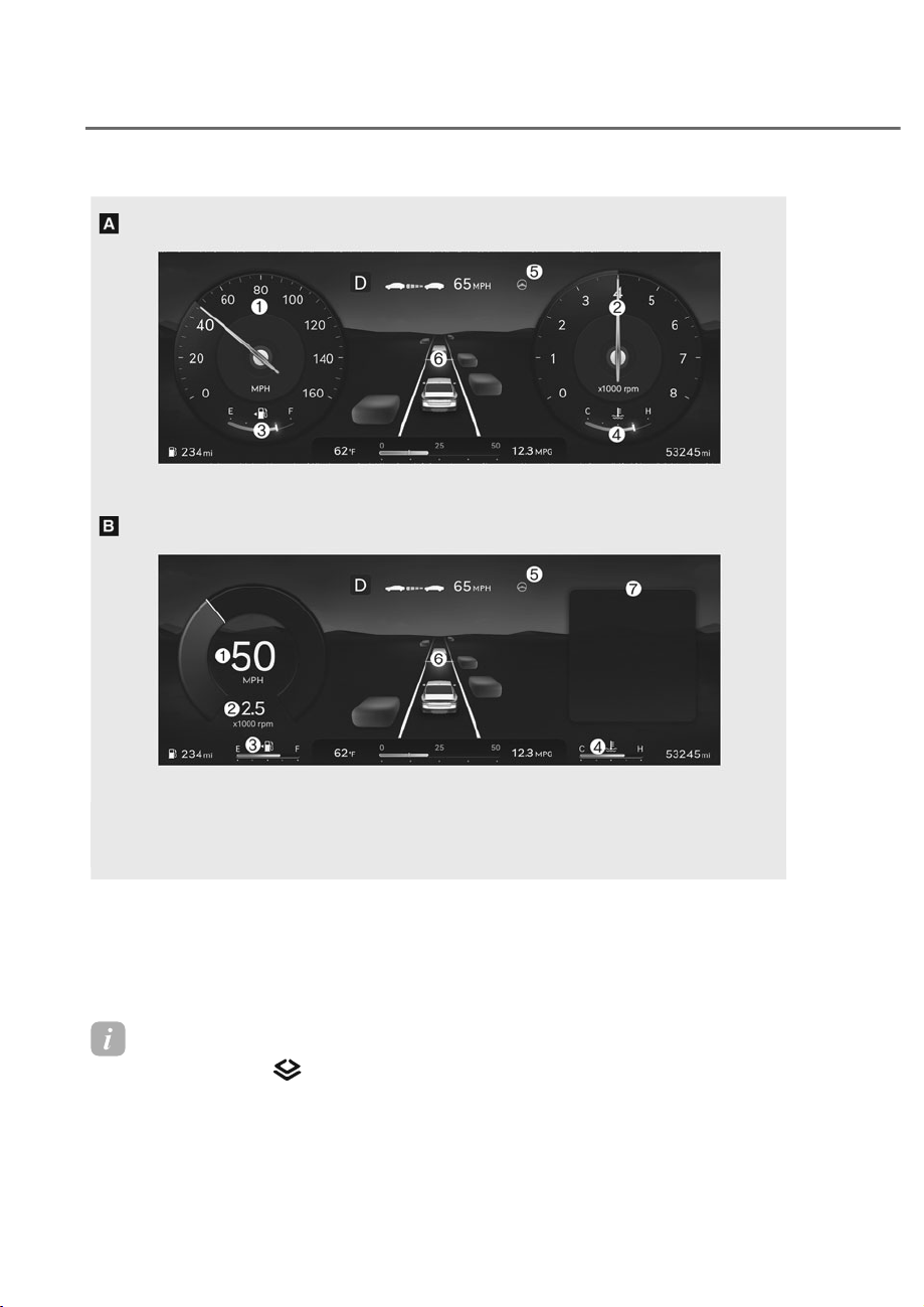
4-4
Instrument Cluster, Armrest touchscreen, Infotainment system
Information
Press the mode button ( ) on the steering wheel to select between instrument cluster
type A or type B.
The actual cluster in the vehicle may differ from the illustration.
For more information, refer to “Gauges and meters” section in this chapter.
ORS042002N/ORS042001N
ORS042002N/ORS042001N
1. Speedometer
2. Tachometer
3. Fuel gauge
4. Engine coolant temperature gauge
5. Warning and indicator lights
6. LCD display
7. Widget
INSTRUMENT CLUSTER
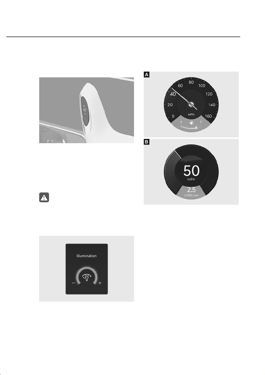
4-5
04
Instrument Cluster Control
Instrument panel illumination
(if equipped)
ORS041003
ORS041003
When the vehicle’s position lights or
headlights are on, press the illumination
control switch to adjust the brightness of
the instrument panel illumination.
When pressing the illumination control
switch, the interior switch illumination
intensity is also adjusted.
WARNING
Never adjust the instrument cluster
while driving. This could result in loss
of control and lead to an accident that
may cause death, serious injury, or
vehicle damage.
OJWEV041001L
OJWEV041001L
• The brightness of the instrument
panel illumination is displayed.
• If the brightness reaches the
maximum or minimum level, a chime
will sound.
Gauges and Meters
Speedometer
ORS042004N
ORS042004N
ORS042005N
ORS042005N
The speedometer indicates the speed of
the vehicle and is calibrated in miles per
hour (MPH) and/or kilometers per hour
(km/h).
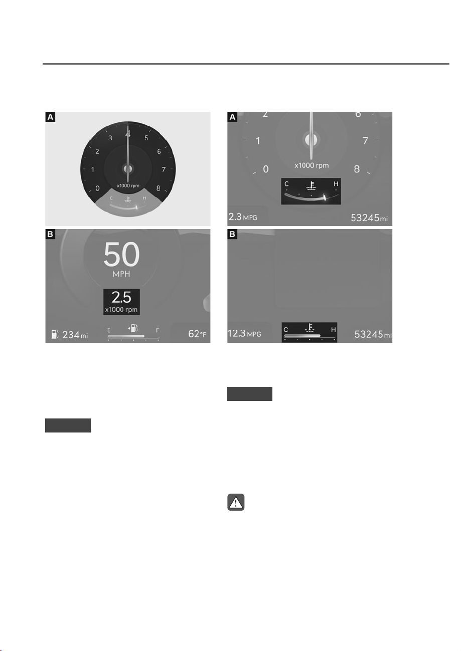
4-6
Instrument Cluster, Armrest touchscreen, Infotainment system
Tachometer
ORS041006
ORS041006
ORS042007N
ORS042007N
The tachometer indicates the
approximate number of engine
revolutions per minute (RPM).
Use the tachometer to select the correct
shift points and to prevent lugging and/
or over-revving the engine.
NOTICE
Do not operate the engine within the
tachometer's RED ZONE. This may
cause severe engine damage.
Engine coolant temperature gauge
ORS042008N
ORS042008N
ORS042009N
ORS042009N
This gauge indicates the temperature
of the engine coolant when the Engine
Start/Stop button is in the ON position.
NOTICE
If the gauge pointer moves beyond the
normal range area toward the “H (Hot)”
position, it indicates overheating that
may damage the engine.
Do not continue driving with an
overheated engine. If your vehicle
overheats, refer to “If the Engine
Overheats” section in chapter 8.
WARNING
Never remove the engine coolant
reservoir cap when the engine is hot.
The engine coolant is under pressure
and could cause severe burn. Wait until
the engine is cool before adding coolant
to the reservoir.
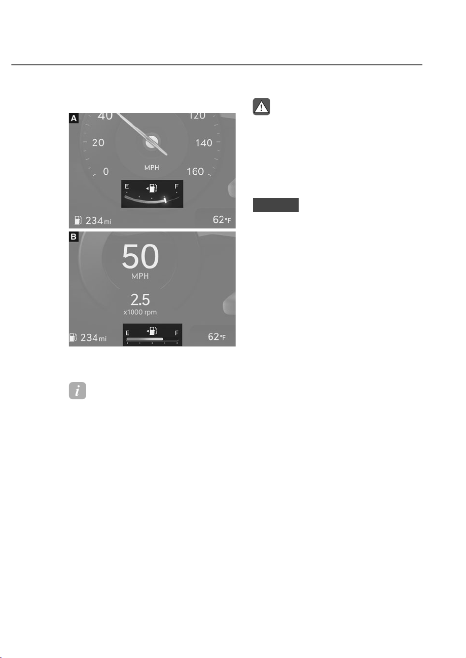
4-7
04
Fuel gauge
ORS042010N
ORS042010N
ORS042011N
ORS042011N
This gauge indicates the approximate
amount of fuel remaining in the fuel tank.
Information
• The fuel tank capacity is given in
chapter 2.
• The fuel gauge is supplemented by
a low fuel warning light, which will
illuminate when the fuel tank is nearly
empty.
• On inclines or curves, the fuel gauge
pointer may fluctuate or the low fuel
warning light may come on earlier than
usual due to the movement of fuel in
the tank.
WARNING
Running out of fuel can expose vehicle
occupants to danger.
You must stop and obtain additional
fuel as soon as possible after the
warning light comes on or when the
gauge indicator comes close to the “E
(Empty)” level.
NOTICE
Avoid driving with an extremely low
fuel level. Running out of fuel could
cause the engine to misfire damaging
the catalytic converter.
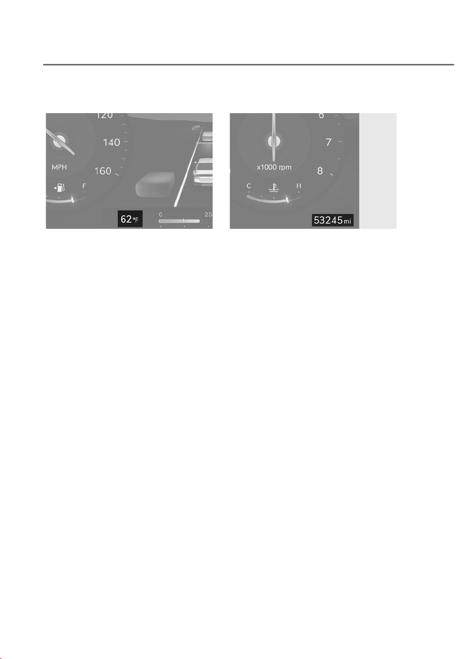
4-8
Instrument Cluster, Armrest touchscreen, Infotainment system
Outside temperature gauge
ORS042012N
ORS042012N
This gauge indicates the current outside
air temperatures by increments of 1°F
(1°C).
Note that the temperature indicated
on the LCD display may not change
as quickly as the outside temperature
(there may be a slight delay before the
temperature changes.)
You can change the temperature
unit from the Settings menu in the
infotainment system screen. Select:
- 6HWXSɌ*HQHUDOɌ8QLWɌ7HPSHUDWXUH
8QLWɌr&r)
See additional information in supplied
Infotainment Manual.
For vehicles equipped with Automatic
Climate Control, you can also:
- Press the AUTO button while pressing
the OFF button on the climate control
unit for 3 seconds
Both the temperature unit on the cluster
LCD display and climate control screen
will change.
Odometer
ORS042014N
ORS042014N
The odometer indicates the total
distance that the vehicle has been
driven and should be used to determine
when periodic maintenance should be
performed.

4-9
04
Distance to empty
ORS042015N
ORS042015N
• The distance to empty is the
estimated distance the vehicle can be
driven with the remaining fuel.
• If the estimated distance is below
1 mi. (1 km), the trip computer will
display "----" as range.
• The trip computer may not register
additional fuel if less than 1.6 gallon
(6 liters) of fuel are added to the
vehicle.
Information
• If the vehicle is not on level ground or
the battery power has been interrupted,
the distance to empty function may not
operate correctly.
• The distance to empty may differ
from the actual driving distance as it
is an estimate of the available driving
distance.
• The distance to empty may vary
significantly based on driving
conditions, driving habits, and
condition of the vehicle.
Fuel economy
ORS042016N
ORS042016N
The average fuel economy M and instant
fuel economy N is displayed at the
bottom of the cluster.
Automatic reset
To automatically reset the average fuel
economy, select between 'After Vehicle
On' or 'After Refueling' from the Settings
menu in the infotainment system screen.
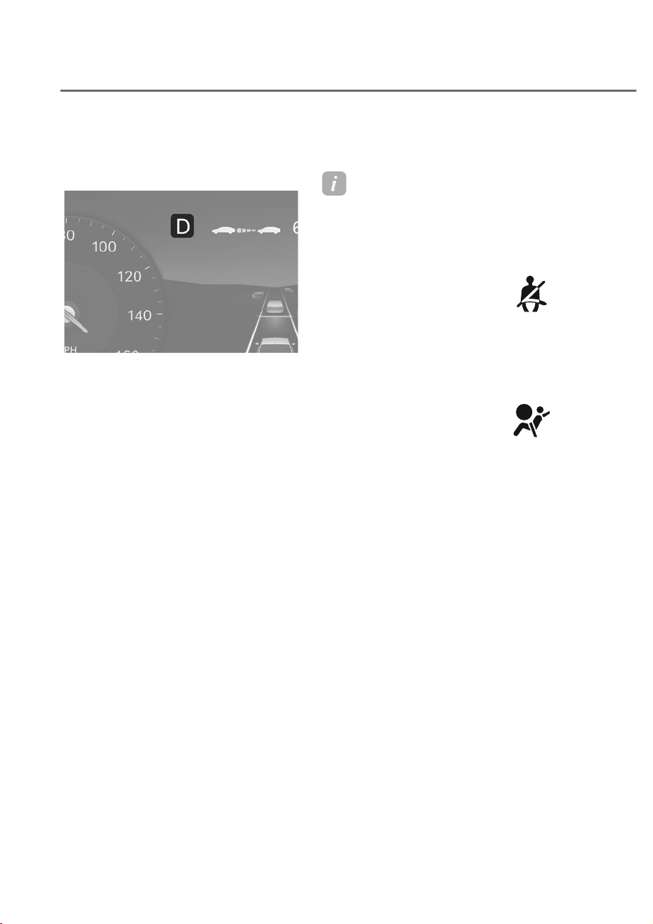
4-10
Instrument Cluster, Armrest touchscreen, Infotainment system
Transmission Shift Indicator
Automatic transmission shift
indicator
ORS042013N
ORS042013N
This indicator informs the current gear
engaged.
Warning and Indicator Lights
Information
Make sure that all warning lights are OFF
after starting the engine. If any light is still
ON, this indicates a situation that needs
attention.
Seat belt warning light
This warning light informs the driver that
the seat belt is not fastened.
For more details, refer to “Seat Belts”
section in chapter 3.
Air bag warning light
This warning light illuminates:
• When you set the Engine Start/Stop
button to the ON position.
- The air bag warning light illuminates
for about 6 seconds and then turns
off when all checks have been
performed.
• The air bag warning light will remain
illuminated if there is a malfunction
with the Safety Restraint System (SRS)
air bag operation.
If this occurs, have the vehicle
inspected by an authorized retailer of
Genesis Branded products.

4-11
04
Parking brake & Brake fluid
warning light
This warning light illuminates:
• When you set the Engine Start/Stop
button to the ON position.
- The parking brake & brake fluid
warning light illuminates for about 3
seconds and will then turn off once
the parking brake is released.
• Whenever the parking brake is
applied.
• Whenever the brake fluid level in the
reservoir is low.
- If the warning light illuminates
with the parking brake released, it
indicates the brake fluid level in the
reservoir is low.
If the brake fluid level in the reservoir is
low:
1. Drive carefully to the nearest safe
location and stop your vehicle.
2. With the engine stopped, check the
brake fluid level immediately and add
fluid as required (For more details,
refer to “Brake Fluid” section in
chapter 9). After adding brake fluid,
check all brake components for fluid
leaks. If a brake fluid leak is found, or
if the warning light remains on, or if
the brakes do not operate properly, do
not drive the vehicle. Have the vehicle
inspected by an authorized retailer of
Genesis Branded products.
Dual-diagonal braking system
Your vehicle is equipped with dual-
diagonal braking system. This means you
still have braking on two wheels even if
one of the dual systems should fail.
With only one of the dual systems
working, more than normal pedal travel
and greater pedal pressure is required to
stop the vehicle.
Also, the vehicle will not stop in as short
a distance with only a portion of the
brake system working.
If the brakes fail while you are driving,
shift to a lower gear for additional engine
braking and stop the vehicle as soon as it
is safe to do so.
WARNING
Parking Brake & Brake Fluid warning
light
Driving the vehicle with a warning light
ON is dangerous. If the Parking Brake
& Brake Fluid warning light illuminates
with the parking brake released, it
indicates that the brake fluid level is
low.
If this occurs, have the vehicle
inspected by an authorized retailer of
Genesis Branded products.
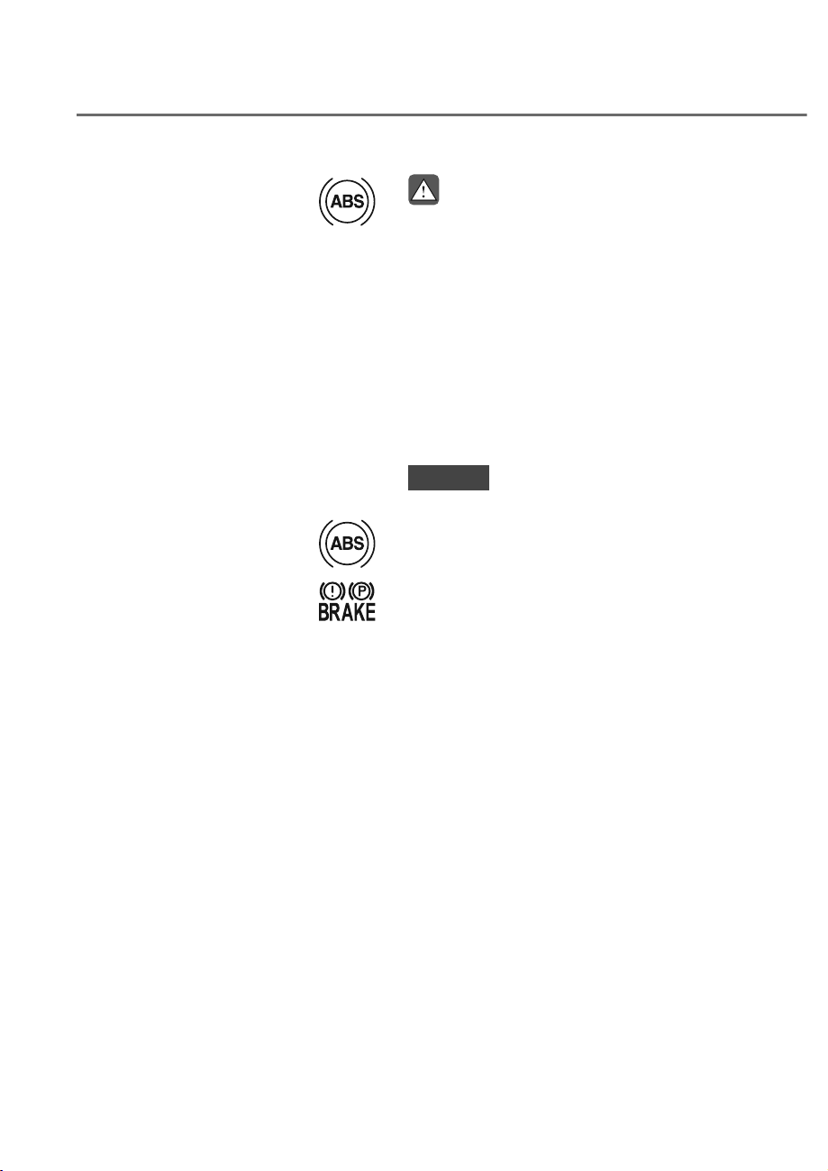
4-12
Instrument Cluster, Armrest touchscreen, Infotainment system
Anti-lock Brake System (ABS)
warning light
This warning light illuminates:
• When you set the Engine Start/Stop
button to the ON position.
- The ABS warning light illuminates
for about 3 seconds and then goes
off.
• Whenever there is a malfunction with
the ABS.
Note that the hydraulic braking
system will still be operational even if
there is a malfunction with the ABS.
If this occurs, have the vehicle
inspected by an authorized retailer of
Genesis Branded products.
Electronic Brake Force
Distribution (EBD) system
warning light
When the ABS warning and
Parking Brake warning lights are on
simultaneously, it may indicate a
problem with the Electronic Brake Force
Distribution system.
If this occurs, have the vehicle inspected
by an authorized retailer of Genesis
Branded products.
WARNING
Electronic Brake Force Distribution
(EBD) system warning light
When both ABS and Parking Brake &
Brake Fluid warning lights are on, the
brake system will not work normally
and you may experience an unexpected
and dangerous situation during sudden
braking.
If this occurs, avoid high speed driving
and abrupt braking.
Have the vehicle inspected by an
authorized retailer of Genesis Branded
products as soon as possible.
NOTICE
Electronic Brake Force Distribution
(EBD) system warning light
When the ABS warning light is on
or both ABS and Parking Brake &
Brake Fluid warning lights are on, the
speedometer, odometer, or tripmeter
may not work. Also, the EPS warning
light may illuminate and the steering
effort may increase or decrease.
If this occurs, have the vehicle
inspected by an authorized retailer of
Genesis Branded products as soon as
possible.

4-13
04
Electric Power Steering (EPS)
warning light
This warning light illuminates:
• When you set the Engine Start/Stop
button to the ON position.
- The electric powering steering
warning light illuminates for about 3
seconds and then goes off.
• Whenever there is a malfunction with
the electric power steering.
If this occurs, have the vehicle
inspected by an authorized retailer of
Genesis Branded products.
Charging system warning
light
This warning light illuminates:
When there is a malfunction with either
the alternator or electrical charging
system.
If there is a malfunction with either the
alternator or electrical charging system:
1. Drive carefully to the nearest safe
location and stop your vehicle.
2. Turn the engine off and check the
alternator drive belt for looseness or
breakage.
If the belt is adjusted properly, there
may be a problem in the electrical
charging system.
If this occurs, have the vehicle
inspected by an authorized retailer of
Genesis Branded products as soon as
possible.
Engine oil pressure warning
light
This warning light illuminates:
When the engine oil pressure is low.
If the engine oil pressure is low:
1. Drive carefully to the nearest safe
location and stop your vehicle.
2. Turn the engine off and check the
engine oil level (For more details, refer
to “Engine Oil” section in chapter 9). If
the level is low, add oil as required.
If the warning light remains on after
adding oil or if oil is not available, have
the vehicle inspected by an authorized
retailer of Genesis Branded products
as soon as possible.
Continued driving with the warning
light on may cause engine failure.
Information
3.5T-GDI, 3.5T-GDI 48 V MHEV
When engine oil pressure decreases due to
insufficient engine oil, etc., the Engine Oil
Pressure warning light will illuminate. In
addition, the enhanced engine protection
system which limits engine power will
be activated. If the engine oil pressure is
restored, the Engine Oil Pressure warning
light and the enhanced engine protection
system will turn off.
However, when the engine oil pressure
is restored, the warning light and the
enhanced engine protection system will
turn off after the engine is restarted.
NOTICE
If the engine is not stopped
immediately after the Engine Oil
Pressure warning light is illuminated
while the engine is running, severe
damage could result.

4-14
Instrument Cluster, Armrest touchscreen, Infotainment system
Low fuel level warning light
This warning light illuminates:
When the fuel tank is nearly empty.
Add fuel as soon as possible.
NOTICE
Driving with the Low Fuel Level warning
light on or with the fuel level below “E”
can cause the engine to misfire and
damage the catalytic converter.
Malfunction Indicator Lamp
(MIL)
This indicator light illuminates:
• When you set the Engine Start/Stop
button to the ON position.
- The malfunction indicator light
illuminates for about 3 seconds and
then goes off.
• Whenever there is a malfunction with
either the emission control system or
the engine or the vehicle powertrain.
If this occurs, have the vehicle
inspected by an authorized retailer of
Genesis Branded products.
NOTICE
• Driving with the Malfunction
Indicator Lamp (MIL) on may cause
damage to the emission control
system which could affect drivability
and/or fuel economy.
• For 3.5T-GDI, 3.5T-GDI 48 V MHEV
If the enhanced engine protection
system becomes activated due to
lack of engine oil, engine power
will be limited. If such condition
continues repeatedly, the
Malfunction Indicator Lamp will
illuminate.
NOTICE
If the Malfunction Indicator Lamp
(MIL) illuminates, potential catalytic
converter damage is possible which
could result in loss of engine power. If
this occurs, have the vehicle inspected
by an authorized retailer of Genesis
Branded products as soon as possible.

4-15
04
Master warning light
This warning light illuminates:
When there is a malfunction in operation
in any of the following systems:
- Forward Collision-Avoidance Assist
malfunction
- Forward Collision-Avoidance Assist
radar blocked
- Blind-Spot Collision-Avoidance Assist
malfunction
- Blind-Spot Collision-Avoidance Assist
radar blocked
- LED headlight malfunction
(if equipped)
- High Beam Assist malfunction
- Smart Cruise Control malfunction
- Smart Cruise Control radar blocked
- Tire Pressure Monitoring System
(TPMS) malfunction
- Rear wheel steering system
malfunction (if equipped)
To identify the details of the warning,
look at the LCD display.
Electronic Parking Brake
(EPB) warning light
This warning light illuminates:
• When you set the Engine Start/Stop
button to the ON position.
- The EPB warning light illuminates
for about 3 seconds and then goes
off.
• Whenever there is a malfunction with
EPB.
If this occurs, have the vehicle
inspected by an authorized retailer of
Genesis Branded products.
Information
The Electronic Parking Brake (EPB)
warning light may illuminate when
the Electronic Stability Control (ESC)
indicator light comes on to indicate that
ESC is not working properly. This does
not indicate malfunction of EPB.

4-16
Instrument Cluster, Armrest touchscreen, Infotainment system
Low tire pressure warning
light
This warning light illuminates:
• When you set the Engine Start/Stop
button to the ON position.
- The low tire pressure warning light
illuminates for approximately 3
seconds and then goes off.
• When one or more of your tires are
significantly underinflated. (The
location of the underinflated tires are
displayed on the LCD display.)
For more details, refer to “Tire Pressure
Monitoring System (TPMS)” section in
chapter 8.
This warning light remains ON after
blinking for approximately 60 seconds, or
repeatedly blinks ON and OFF in 3 second
intervals:
When there is a malfunction with the
TPMS.
If this occurs, have the vehicle inspected
by an authorized retailer of Genesis
Branded products as soon as possible.
For more details, refer to “Tire Pressure
Monitoring System (TPMS)” section in
chapter 8.
WARNING
Safe Stopping
• The TPMS cannot alert you to severe
and sudden tire damage caused by
external factors.
• If you notice any vehicle instability,
immediately take your foot off the
accelerator pedal, apply the brakes
gradually with light force, and slowly
move to a safe position off the road.
Forward Safety warning light
This warning light illuminates:
• When the Engine Start/Stop button is
in the ON position. It illuminates for
about 3 seconds and then goes off.
• Yellow: When Forward Safety of
Forward Collision-Avoidance Assist is
deselected, disabled, or a malfunction
is detected.
If the yellow warning light remains on
after the sensor has been uncovered
or unblocked when Forward Safety is
set, have the vehicle inspected by an
authorized retailer of Genesis Branded
products.
This warning light blinks:
• Red: When Forward Safety or Forward
Cross-Traffic Safety function is
operating.
For more information, refer to the
"Forward Collision-Avoidance Assist"
section in chapter 7.
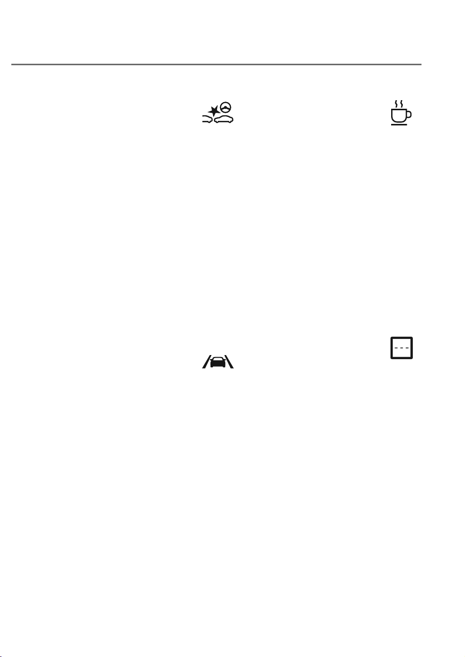
4-17
04
Emergency Steering warning
light
This warning light illuminates:
• When the Engine Start/Stop button is
in the ON position. It illuminates for
about 3 seconds and then goes off.
• Yellow: When Forward/Side Safety of
Forward Collision-Avoidance Assist is
deselected, disabled, or a malfunction
is detected.
If the warning light remains on after the
sensor has been uncovered or unblocked
when Forward/Side Safety is set, have
the vehicle inspected by an authorized
retailer of Genesis Branded products.
This warning light blinks:
• Red: When Forward/Side Safety
function is operating.
For more information, refer to the
"Forward Collision-Avoidance Assist"
section in chapter 7.
Lane Safety indicator light
This indicator light illuminates:
• When the ignition switch3) is in the
ON position. It illuminates for about 3
seconds and then goes off.
• Gray: When Lane Keeping Assist
operating conditions are not satisfied.
• Green: When Lane Keeping Assist
operating conditions are satisfied.
• Yellow: When Lane Safety is disabled,
or a malfunction is detected.
If the yellow warning light remains on
after the sensor has been uncovered or
unblocked when Lane Safety is set, have
the vehicle inspected by an authorized
retailer of Genesis Branded products.
For more details, refer to “Lane Keeping
Assist (LKA)” section in chapter 7.
Driver Attention warning
indicator light
This warning light illuminates:
• When the Engine Start/Stop button is
in the ON position. It illuminates for
about 3 seconds and then goes off.
• Yellow: When Driver Attention
Warning is disabled or a malfunction
is detected.
If the yellow indicator light remains
on after the front view camera has
been uncovered or unblocked, have
the vehicle inspected by an authorized
retailer of Genesis Branded products.
This warning light blinks:
• Yellow: Driver Attention Warning
recommends to take a break.
For more information, refer to the "Driver
Attention Warning" section in chapter 7.
Intelligent Speed Limit Assist
indicator light
This warning light illuminates:
• When the Engine Start/Stop button is
in the ON position. It illuminates for
about 3 seconds and then goes off.
• Yellow: Whem Intelligent Speed Limit
Assist is off, disabled, or a malfunction
is detected.
If the yellow indicator light remains
on after the front view camera has
been uncovered or unblocked, have
the vehicle inspected by an authorized
retailer of Genesis Branded products.
For more information, refer to the
"Intelligent Speed Limit Assist" section in
chapter 7.

4-18
Instrument Cluster, Armrest touchscreen, Infotainment system
All Wheel Drive (AWD)
warning light (if equipped)
This warning light illuminates:
Whenever there is a malfunction with the
AWD system.
If this occurs, have the vehicle inspected
by an authorized retailer of Genesis
Branded products.
For more details, refer to "All Wheel Drive
(AWD)" section in chapter 6.
LED headlight warning light
This warning light illuminates:
• When you set the Engine Start/Stop
button to the ON position.
- The LED headlight warning light
illuminates for approximately 3
seconds and then goes off.
• Whenever there is a malfunction with
the LED headlight.
If this occurs, have the vehicle
inspected by an authorized retailer of
Genesis Branded products.
This warning light blinks:
Whenever there is a malfunction with a
LED headlight related part.
If this occurs, have the vehicle inspected
by an authorized retailer of Genesis
Branded products.
NOTICE
Continuous driving with the LED
Headlight warning light on or blinking
can reduce LED headlight life.
Icy road warning light
(if equipped)
This warning light is to warn the driver
the road may be icy.
When the temperature on the outside
temperature gauge is approximately
below 40°F (4°C), the Icy Road warning
light and Outside Temperature Gauge
blinks and then illuminates. Also, the
warning chime sounds 1 time.
You can activate or deactivate Icy Road
Warning function from the Settings
menu in the infotainment system screen.
Select:
- 6HWXSɌ9HKLFOHɌ&OXVWHUɌ&RQWHQW
6HOHFWLRQɌ,F\5RDG:DUQLQJ
See additional information in supplied
Infotainment Manual.
Information
If the Icy Road warning light appears
while driving, you should drive more
attentively and safely refraining from
over-speeding, rapid acceleration, sudden
braking or sharp turning, etc.

4-19
04
Electronic Stability Control
(ESC) indicator light
This indicator light illuminates:
• When you set the Engine Start/Stop
button to the ON position.
- The Electronic Stability Control
indicator light illuminates for about
3 seconds and then goes off.
• Whenever there is a malfunction with
ESC system.
If this occurs, have the vehicle
inspected by an authorized retailer of
Genesis Branded products.
This indicator light blinks:
While ESC is operating.
For more details, refer to “Electronic
Stability Control (ESC)” section in
chapter 6.
Electronic Stability Control
(ESC) OFF indicator light
This indicator light illuminates:
• When you set the Engine Start/Stop
button to the ON position.
- The ESC OFF indicator light
illuminates for approximately 3
seconds and then goes off.
• When you deactivate ESC system by
pressing the ESC OFF button.
For more details, refer to “Electronic
Stability Control (ESC)” section in
chapter 6.
Immobilizer indicator light
This indicator light illuminates for up to
30 seconds:
When the vehicle detects the smart key
in the vehicle with the Engine Start/Stop
button in the ACC or ON position.
- Once the smart key is detected, you
can start the engine.
- The indicator light goes off after
starting the engine.
This indicator light blinks for a few
seconds:
When the smart key is not in the vehicle.
- If the smart key is not detected, you
cannot start the engine.
This indicator light illuminates for 2
seconds and goes off:
If the smart key is in the vehicle and the
Engine Start/Stop button is ON, but the
vehicle cannot detect the smart key.
If this occurs, have the vehicle inspected
by an authorized retailer of Genesis
Branded products.
This indicator light blinks:
Whenever there is a malfunction with the
immobilizer system.
If this occurs, have the vehicle inspected
by an authorized retailer of Genesis
Branded products.

4-20
Instrument Cluster, Armrest touchscreen, Infotainment system
AUTO STOP indicator light
(if equipped)
This indicator light illuminates:
When the engine enters the Idle Stop
mode of ISG (Idle Stop and Go) system.
This indicator light blinks:
When the engine automatically starts,
the AUTO STOP indicator on the cluster
will blink for 5 seconds.
For more details, refer to "ISG (Idle Stop
and Go) system" section in chapter 6.
Information
When the engine automatically starts
by the ISG system, some warning lights
(ABS, ESC, ESC OFF, MDPS or Parking
brake warning light) may turn on for a
few seconds. This happens because of
low battery voltage. It does not mean the
system has malfunctioned.
Turn signal indicator light
This indicator light blinks:
When you operate the turn signal
indicator stalk.
If any of the following occur, there may
be a malfunction with the turn signal
system.
- The turn signal indicator light
illuminates but does not blink
- The turn signal indicator light blinks
rapidly
- The turn signal indicator light does not
illuminate at all
If any of these conditions occur, have
the vehicle inspected by an authorized
retailer of Genesis Branded products.
High beam indicator light
This indicator light illuminates:
• When the headlights are on and in the
high beam position
• When the turn signal lever is pulled
into the Flash-to-Pass position.
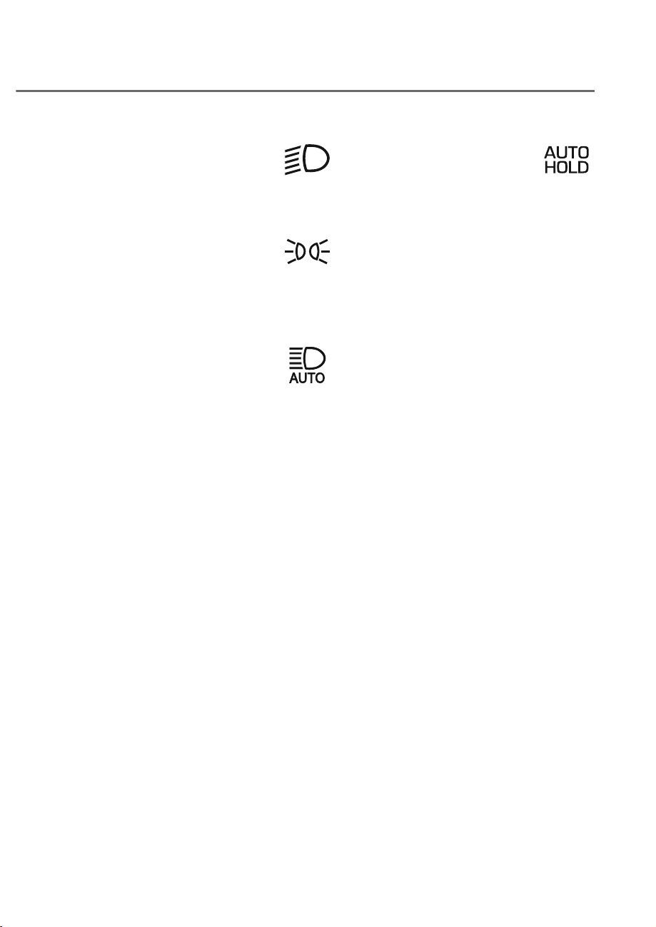
4-21
04
Low beam indicator light
This indicator light illuminates:
When the headlights are on.
Light ON indicator light
This indicator light illuminates:
When the parking lamps or headlights
are on.
High Beam Assist indicator
light
This indicator light illuminates:
When the high-beam is on with the light
switch in the AUTO position.
• White: When High Beam Assist is
ready to operate.
• Green: When High Beam Assist is
operating.
If your vehicle detects oncoming or
preceding vehicles, High Beam Assist
will switch the high beam to low beam
automatically.
For more details, refer to “High Beam
Assist (HBA)” section in chapter 5.
AUTO HOLD indicator light
This indicator light illuminates:
• White: When you activate Auto Hold
by pressing the AUTO HOLD switch.
• Green: When you stop the vehicle
completely by depressing the brake
pedal with Auto Hold activated.
• Yellow: Whenever there is a
malfunction with the Auto Hold
function.
If this occurs, have the vehicle inspected
by an authorized retailer of Genesis
Branded products.
For more details, refer to “Electronic
Parking Brake (EPB)” section in chapter
6.

4-22
Instrument Cluster, Armrest touchscreen, Infotainment system
LCD Display Messages
Vehicle is on
This message is displayed if you open the
driver’s door when the gear is in P (Park)
and the Engine Start/Stop button in the
ON or START position.
Turn the engine off before leaving the
vehicle.
Shift to P
This message is displayed if you try to
turn off the vehicle without the gear in
the P (Park) position.
If this occurs, the Engine Start/Stop
button turns to the ACC position.
Vehicle is in N. Press START button
and shift to P
This message is displayed if you try to
turn off the vehicle with the gear in N
(Neutral).
To turn off the vehicle:
1. Press the Engine Start/Stop button.
The button will change to the ON
position.
2. Press the P button to shift to P (Park).
3. Press the Engine Start/Stop button
again, then the vehicle will turn off.
Low key battery
This message is displayed if the battery
of the smart key is discharged while
changing the Engine Start/Stop button to
the OFF position.
Press brake pedal to start engine
This message is displayed if the Engine
Start/Stop button changes to the ACC
position twice by pressing the button
repeatedly without depressing the brake
pedal.
You can start the vehicle by depressing
the brake pedal and then pressing the
Engine Start/Stop button.
Key not in vehicle
This message is displayed if the smart
key is not in the vehicle when you leave
the vehicle with the Engine Start/Stop
button in the ON or Start position.
Always turn off the engine before leaving
your vehicle.
Key not detected
This message is displayed if the smart
key is not detected when you press the
Engine Start/Stop button.
Press START button again
This message is displayed if you were
unable to start the vehicle when the
Engine Start/Stop button was pressed.
If this occurs, attempt to start the engine
by pressing the Engine Start/ Stop button
again.
If the warning message appears each
time you press the Engine Start/Stop
button, we recommend that you have
the vehicle inspected by an authorized
retailer of Genesis Branded products.

4-23
04
Press START button with key
(if equipped)
This message is displayed if you press
the Engine Start/Stop button while the
warning message “Key not detected” is
displayed.
At this time, the immobilizer indicator
light blinks.
Check BRAKE SWITCH fuse
This message is displayed if the brake
switch fuse is disconnected.
You need to replace the fuse with a new
one before starting the engine.
If that is not possible, you can start the
engine by pressing the Engine Start/
Stop button for 10 seconds in the ACC
position.
Shift to P or N to start engine
This message is displayed if you try to
start the engine in any other position
except P (Park) or N (Neutral).
Information
You can start the engine with the gear
in N (Neutral). But, for your safety, we
recommend that you start the engine with
the gear shifted to P (Park).
Battery discharging due to external
electrical devices (if equipped)
This message is displayed if the 12V
battery voltage is weak due to any
non-factory electrical accessories (ex.
dashboard camera) while parking. Be
careful that the battery is not discharged.
If the message appears after removing
the non-factory electrical accessories,
have the vehicle inspected by an
authorized retailer of Genesis Branded
products.
Check rear wheel steering system
(if equipped)
This message is displayed if the rear
wheel steering system or related
devices is not working properly. Also,
The warning light will illuminate on the
cluster. If the message appares after
engine is restarted, have the vehicle
inspected by an authorized retailer of
Genesis Branded products.
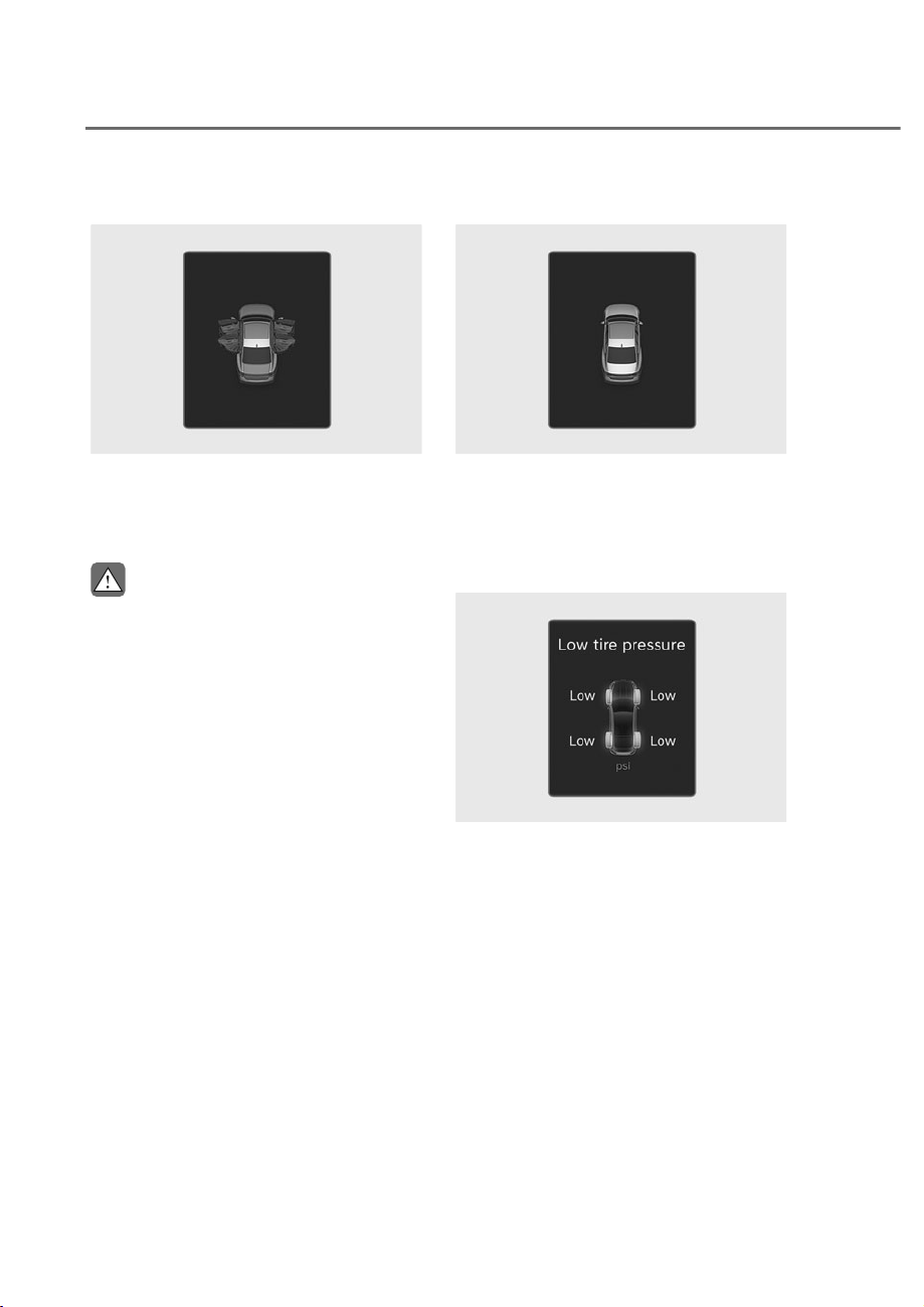
4-24
Instrument Cluster, Armrest touchscreen, Infotainment system
Door, Hood, trunk open indicator
ORS041021
ORS041021
This warning is displayed if any door or
hood or trunk is left open. The warning
will indicate which door is open in the
display.
CAUTION
Before driving the vehicle, you should
confirm that the door, hood and trunk
are fully closed.
Sunroof open indicator (if equipped)
ORS041022
ORS041022
This warning is displayed if you turn off
the engine when the sunroof is open.
Close the sunroof securely before leaving
your vehicle.
Low tire pressure
ORS041024L
ORS041024L
This warning message is displayed if the
tire pressure is low. The corresponding
tire on the vehicle will be illuminated.
For more details, refer to “Tire Pressure
Monitoring System (TPMS)” section in
chapter 8.
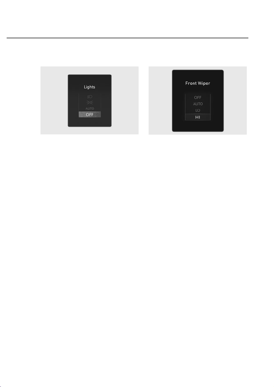
4-25
04
Lights
OJWEV041023L
OJWEV041023L
This indicator displays which exterior
light is selected using the lighting
control.
You can activate or deactivate Wiper/
Lights display function from the Settings
menu in the infotainment system screen.
Select:
- 6HWXSɌ9HKLFOHɌ&OXVWHUɌ&RQWHQW
6HOHFWLRQɌ:LSHU/LJKWV'LVSOD\
See additional information in supplied
Infotainment Manual.
Wiper
OJX1049008L
OJX1049008L
This indicator displays which wiper speed
is selected using the wiper control.
You can activate or deactivate Wiper/
Lights display function from the Settings
menu in the infotainment system screen.
Select:
- 6HWXSɌ9HKLFOHɌ&OXVWHUɌ&RQWHQW
6HOHFWLRQɌ:LSHU/LJKWV'LVSOD\
See additional information in supplied
Infotainment Manual.

4-26
Instrument Cluster, Armrest touchscreen, Infotainment system
Low washer fluid
This message is displayed if the washer
fluid level in the reservoir is nearly empty.
Have the washer fluid reservoir refilled.
Low fuel
This message is displayed if the fuel tank
is almost out of fuel.
When this message is displayed, the low
fuel level warning light in the cluster will
come on.
It is recommended to look for the nearest
fueling station and refuel as soon as
possible.
Low engine oil (if equipped)
This warning message is displayed when
the engine oil level should be checked.
If this warning message is displayed,
check the engine oil level as soon as
possible and add engine oil as required.
Slowly pour the recommended oil little
by little into a funnel.
Use only the specified engine oil. (Refer
to "Recommended Lubricants and
Capacities“ section in chapter 2.)
Do not overfill the engine oil. Make sure
the oil level is not above F (Full) mark on
the dipstick.
Information
If you add engine oil, the warning message
should disappear. If the warning message
reappears after driving approximately
31~62 miles (50~100 km), have the vehicle
inspected by an authorized retailer of
Genesis Branded products as soon as
possible.
Engine overheated
This message is displayed when the
engine coolant temperature is above
248°F (120°C). This means that the
engine is overheated and may be
damaged.
If your vehicle is overheated, refer to
“Overheating” section in chapter 8.
Check haptic steering wheel system
This message is displayed if there is a
problem with the haptic steering wheel
system. Have the vehicle inspected by an
authorized retailer of Genesis Branded
products.
Check headlight (if equipped)
This message is displayed if the
headlights are not operating properly. A
lamp may need to be replaced.
Make sure to replace the burned out
bulb with a new one of the same wattage
rating.
Check turn signal (if equipped)
This message is displayed if the turn
signal lamps are not operating properly.
A lamp may need to be replaced.
Make sure to replace the burned out
bulb with a new one of the same wattage
rating.
Check headlight LED (if equipped)
This message is displayed if there is a
problem with the LED headlight. Have
the vehicle inspected by an authorized
retailer of Genesis Branded products.
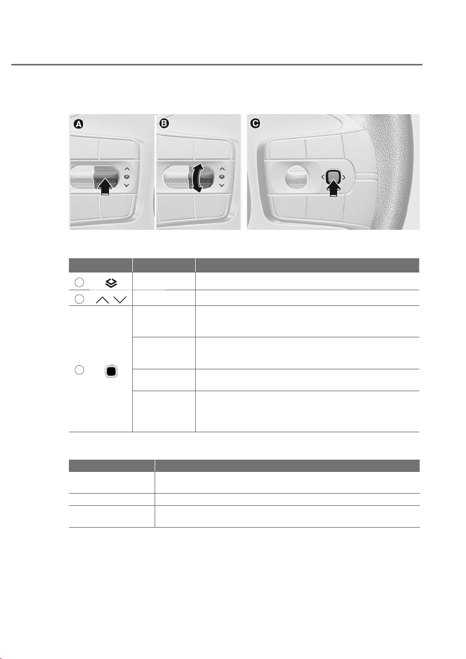
4-27
04
The LCD display modes can be changed by using the control switches.
Switch Operation Function
A
Press MODE button for changing gauge mode
B
,
Press UP, DOWN switch for changing View modes
C
Press
SELECT/RESET switch for selecting pop up
SELECT/RESET switch for entering or exiting widget
navigation mode
Press and hold
SELECT/RESET switch for selecting certain pop up
SELECT/RESET switch for hiding or showing widget
mode
Press 2 times
SELECT/RESET switch for resetting the selected Normal
view mode
Tap up, down,
left, right
When in widget mode, the switch is used to navigate the
widgets.
When not in widget mode, the switch is used to change
to previous or next song.
View Modes
View modes Explanation
Driving Assist view
Driving Assist view displays the status of the vehicle’s Driver
Assistance systems
Map view Show map and navigation related information
Normal view
Show trip computer or widget on center without background
information
The information provided may differ depending on which functions are applicable
to your vehicle.
LCD DISPLAY
LCD Display Control
ORS042043
ORS042043
ORS042044
ORS042044
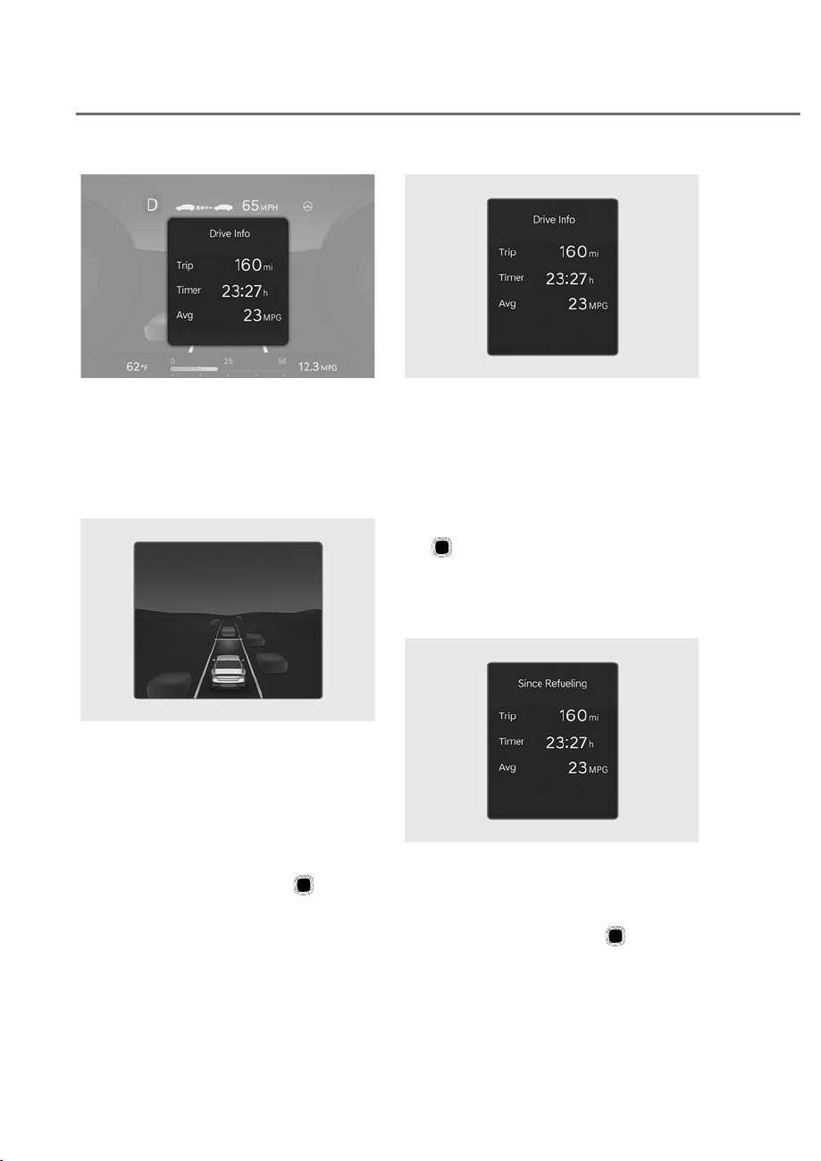
4-28
Instrument Cluster, Armrest touchscreen, Infotainment system
ORS042035N
ORS042035N
Driving Assist, Map and Normal View
modes are displayed in the instrument
cluster.
Normal view is also show in the widget
mode.
Driving Assist view
ORS041026
ORS041026
The status of Smart Cruise Control, Lane
Following Assist, Highway Driving Assist,
etc. is displayed when Driving Assist view
is selected.
For more details, refer to each system
information section in chapter 6.
Normal View
In the Normal View, using the (Optical
mouse), you may change through items
in the following order.
ORS042025N
ORS042025N
Drive info
Trip distance, average fuel economy, and
total driving time are displayed.
The information is combined for each
ignition cycle. However, when the engine
has been OFF for 4 hours or longer the
Drive Info screen will reset.
To manually reset the information, press
the
button three times on the steering
wheel when Drive Info is displayed.
The trip distance, the average fuel
economy, and total driving time will reset
simultaneously.
ORS042029N
ORS042029N
Since refueling
Trip distance, average fuel economy, and
total driving time after the vehicle has
been refueled are displayed.
To reset manually, press the
button
three times on the steering wheel when
‘Since Refueling’ is displayed.
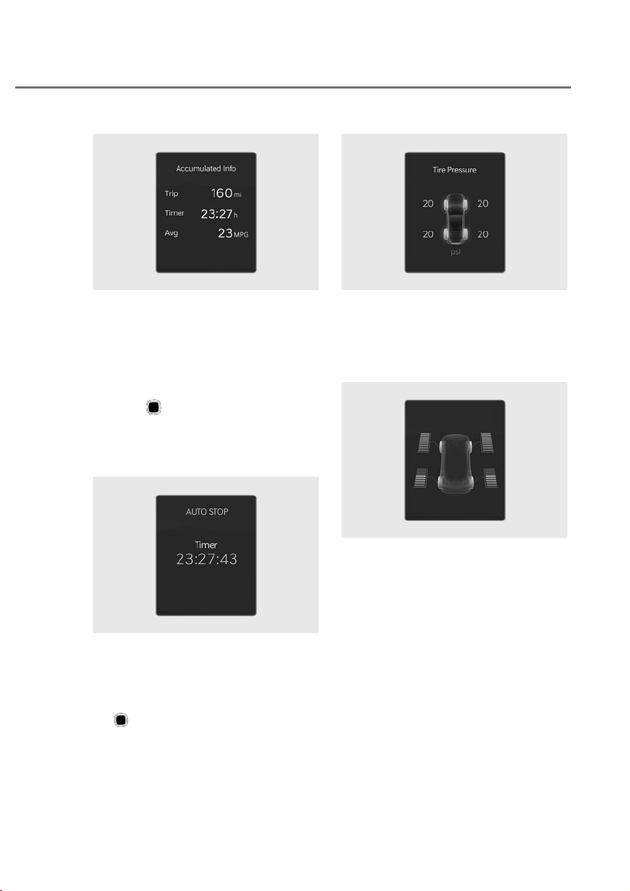
4-29
04
ORS042028N
ORS042028N
Accumulated info
Accumulated trip distance, average fuel
economy, and total driving time are
displayed.
The information is accumulated starting
from the last reset.
To manually reset the information,
press the
button three times on the
steering wheel when Accumulated Info is
displayed. The trip distance, the average
fuel economy, and total driving time will
reset simultaneously.
ORS041031L
ORS041031L
Auto stop (if equipped)
AUTO STOP display shows the elapsed
time of engine stop by Idle Stop and Go
system.
To manually reset the information, press
the
button three times on the steering
wheel when ‘AUTO STOP’ is displayed.
For more details, refer to “Idle Stop and
Go (ISG)” section in chapter 6.
ORS041032L
ORS041032L
Tire pressure
The tire pressure of each tire is displayed.
For more details, refer to “Tire Pressure
Monitoring System (TPMS)” section in
chapter 8.
ORS041030L
ORS041030L
Driving force distribution (if equipped)
The distribution status of the driving
power of the front and rear wheels are
displayed when Auto 4WD mode is
activated.
For more details, refer to "Four Wheel
Drive (4WD)" section in chapter 6.
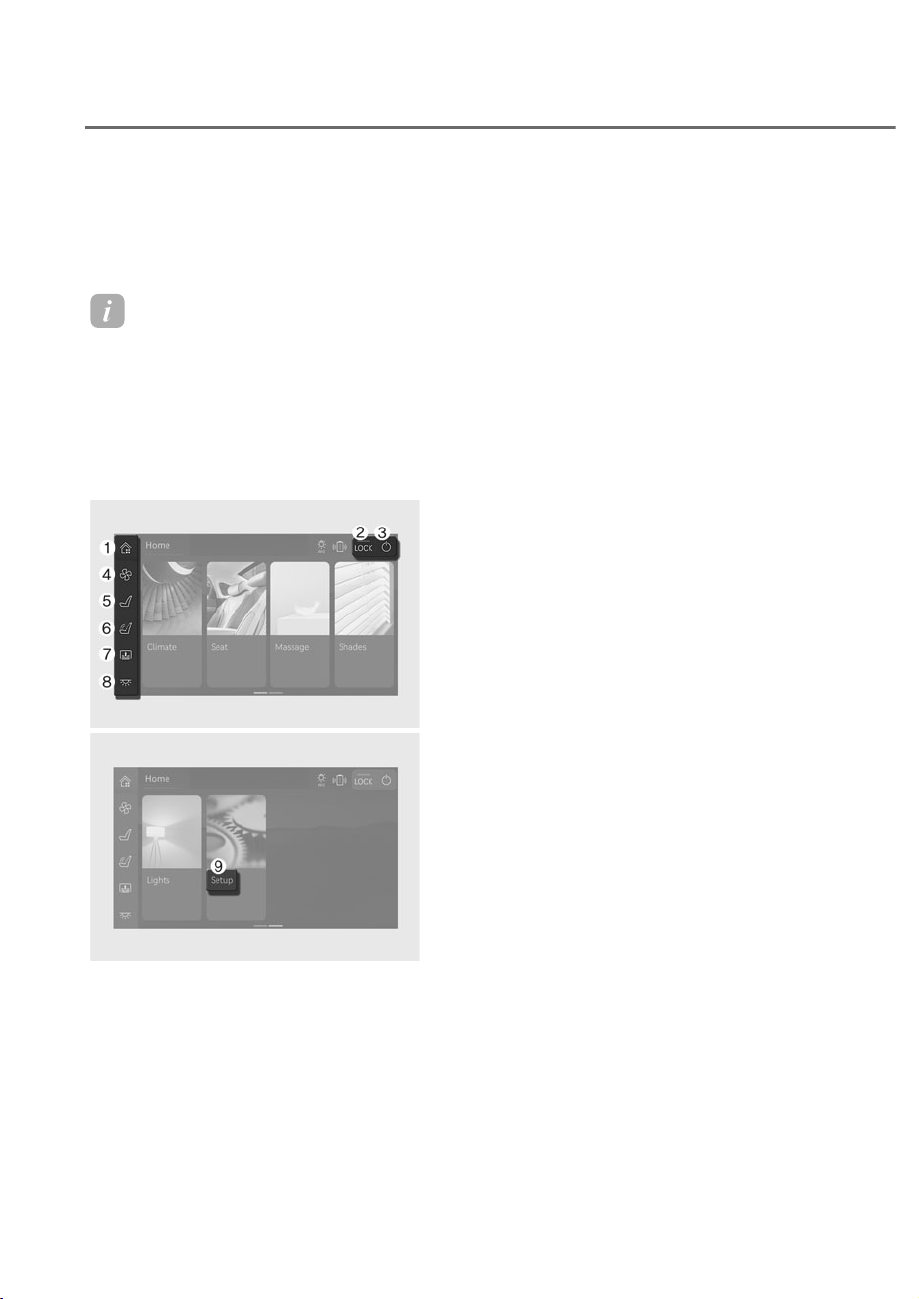
4-30
Instrument Cluster, Armrest touchscreen, Infotainment system
ARMREST TOUCHSCREEN
The armrest touchscreen on the rear
seat allows occupants to access various
functions of the vehicle. Tap the screen
twice quickly to start.
Information
Functions available from the armrest
touchscreen may vary depending on
vehicle specifications.
Operating the touchscreen
Press the button on the upper left or
right of the screen to either: display
home screen, lock or turn off the screen.
ORS031106L
ORS031106L
ORS031107L
ORS031107L
1. Home: Returns to the home screen.
2. LOCK: Locks the rear armrest touch
screen and infotainment system
controller to disable its operation.
Press LOCK again to unlock. Only the
POWER button can be operated while
locked.
3. POWER: Turns off the touchscreen.
The touchscreen automatically turns
off if there are no movements in the
screen for 2 minutes. You can change
the settings from the display menu.
Using Touchscreen Functions
To use convenience functions, press the
menus from the home screen or the left
side menu of the touchscreen.
4. Climate: Heater and air conditioner
can be operated from the rear seat.
For more details, refer to “Automatic
Climate Control System” section in
chapter 5 or “Seat warmers”, “Air
ventilation seats” section in chapter 3.
5. Seat: Adjusts seat positions and
operates convenience functions
equipped on the rear seat. For more
details, refer to “Rear seats” section in
chapter 3.
6. Massage (if equipped): Operates
body massage functions. For more
details, refer to “Rear seats” section in
chapter 3.
7. Shades: Operates powered sunshades
for the rear seats. For more details,
refer to “Panorama sunroof”, “Rear
side window sunshades” and “Rear
window sunshade” section in chapter
5.
8. Lights: Turns on or off the indoor
lighting. Adjusts the color temperature
and brightness of the lighting. For
more details, refer to “Interior lights”
section in chapter 5.
9. Setup: Access to other functions
or changes the setting of the
touchscreen. For more details, refer to
“Setting touchscreen” section in this
chapter.

4-31
04
Setting Touchscreen
Press Setup from the main menu of the
touchscreen.
Settings for other functions can be
accessed on the left side of the Setup
(
) menu.
• Fragrance (if equipped): Select the
fragrance for pleasant riding. For more
details, refer to “Built in diffuser”
section in chapter 5.
• Seat (if equipped): Select different
seat modes for rear right seat
occupant. For more details, refer to
“Seats” section in chapter 3.
• Rear Wireless Charging (if equipped):
Turn on/off the wireless cellphone
charge function for rear seat
occupants. For more details, refer
to “Wireless smart phone charging
system” section in chapter 5.
• Display: Change the screensaver
timeout setting and screen display
method while using massage buttons
from the rear door.
- Screen Time-out: 15 sec, 30 sec, 1
Min, 2 Min (default),5 Min, 10 Min
- Massage Notification/Status
(if equipped): Massage Screen
(default), Pop-up, OFF
• Graphic Themes: Select the display
theme of the screen.
- Use Audio System's Display Theme
(default)
- User-Set Time : Select between
white and black theme, or set the
screen to change automatically to
white theme during the day and
black during the night.
• Illumination: Select the brightness of
the screen.
- Adjust Brightness Automatically:
The brightness of the display is
automatically adjusted depending
on outside brightness.
- Manual adjustment: Manually adjust
the brightness to desired level.
Brightness is maintained at the
adjusted level.
- Reset: Returns all settings to
default.
• Blue Light Filter: Select whether to
turn the blue light filter on or off, and
set the color when the blue light lifter
is on.
- Use Blue light filter/color
adjustment: Select or deselect
whether to use the blue light filter,
and adjusts the display color when
the blue light filter is on.
- Auto: Adjusted blue light filter is
turned on automatically when the
surrounding area is dark.
- User-Set Time: Adjusted blue light
filter turns on at the time set.
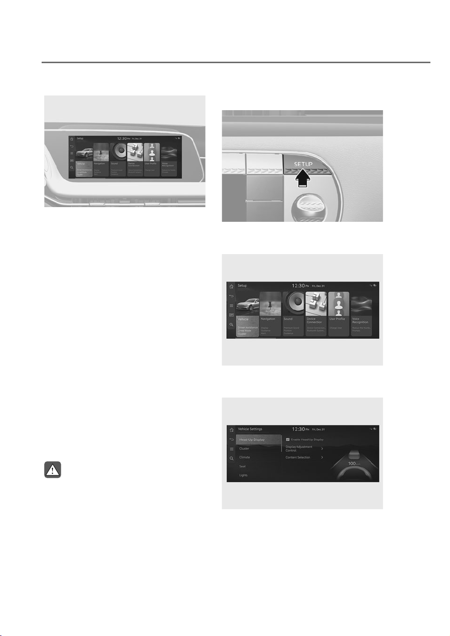
4-32
Instrument Cluster, Armrest touchscreen, Infotainment system
9(+,&/(6(77,1*6ʚ,1)27$,10(176<67(0ʛ
ORS041020L
ORS041020L
Vehicle Settings in the infotainment
system provides user options for a
variety of settings including door lock/
unlock features, convenience features,
driver assistance settings, etc.
Vehicle Settings menu
- Driver Assistance
- Drive Mode
- Active Sound Design
- Head-Up Display
- Cluster
- Climate
- Seat
- Lights
- Door
- Digital key
- Convenience
The information provided may differ
depending on which functions are
applicable to your vehicle.
WARNING
Do not operate the Vehicle Settings
while driving. This may cause
distraction resulting in an accident.
Setting Your Vehicle
ORS041019
ORS041019
1. Press the SETUP button on the head
unit of the infotainment system.
ORS041033L
ORS041033L
2. Select ‘Vehicle’ to change the Vehicle
Settings.
ORS041034L
ORS041034L
See additional information in supplied
Infotainment Manual.

5
Accessing Your Vehicle ..................................................................................... 5-6
Using Smart Key ...........................................................................................................5-6
Smart Key Precautions
.............................................................................................. 5-11
Replacing the Battery
............................................................................................... 5-13
Immobilizer System
.................................................................................................. 5-14
Genesis Digital Key .........................................................................................5-16
Digital Key (Smart Phone) ......................................................................................... 5-16
Digital Key (Card Key)
................................................................................................ 5-22
Personalized Profile and Vehicle Settings
.............................................................. 5-25
Used Vehicle/Digital Key Maintenance
................................................................... 5-28
Limitations of the System
......................................................................................... 5-28
Fingerprint authentication system ................................................................5-29
Fingerprint Authentication System Settings .......................................................... 5-29
Fingerprint Authentication System Operation
....................................................... 5-30
Limitations of the System
......................................................................................... 5-31
When purchasing a used vehicle
............................................................................. 5-31
Door locks........................................................................................................5-32
Operating Door Locks from Outside the Vehicle ................................................... 5-32
Power Door Latch
...................................................................................................... 5-37
Operating Door Locks from Inside the Vehicle
....................................................... 5-38
Easy Door Close
......................................................................................................... 5-41
Automatic Door Lock and Unlock Features
............................................................. 5-43
Electronic Child Safety Lock
..................................................................................... 5-44
Theft-Alarm System ........................................................................................5-46
Advanced Rear Occupant Alert (ROA)
..........................................................5-47
System Setting........................................................................................................... 5-47
System Operation
...................................................................................................... 5-47
System Precautions
................................................................................................... 5-48
Declaration of Conformity
........................................................................................ 5-49
Integrated memory system ............................................................................5-50
Storing Memory Positions ....................................................................................... 5-51
Recalling Memory Positions
..................................................................................... 5-51
Seat Easy Access
....................................................................................................... 5-52
Resetting the System
................................................................................................ 5-53
Smart Posture Care System ...........................................................................5-54
5. Convenience Features

5
Steering Wheel ................................................................................................5-55
Motor Driven Power Steering (MDPS) ..................................................................... 5-55
Tilt/Telescopic Steering
............................................................................................ 5-56
Horn............................................................................................................................ 5-57
Heated Steering Wheel
............................................................................................. 5-57
Steering Wheel Grip Sensor...................................................................................... 5-59
Haptic Warning/Steering Wheel Vibration Warning
............................................... 5-59
Rear Wheel Steering (RWS)
..................................................................................... 5-59
Mirrors .............................................................................................................5-61
Inside Rearview Mirror .............................................................................................. 5-61
Side View Mirrors
...................................................................................................... 5-71
Reverse Parking Aid
.................................................................................................. 5-74
Windows .......................................................................................................... 5-75
Power Windows ......................................................................................................... 5-76
Remote Window Open Feature (Remote Window Control)
................................... 5-79
Panoramic Sunroof .........................................................................................5-80
Power Sunshade ........................................................................................................ 5-80
Tilt Open/Close.......................................................................................................... 5-82
Slide Open/Close
...................................................................................................... 5-82
Automatic Reverse
.................................................................................................... 5-83
Resetting the Sunroof
............................................................................................... 5-84
Rear Seat Power Sunshade
....................................................................................... 5-85
Sunroof Open Warning
............................................................................................ 5-85
Hood ................................................................................................................5-86
Opening the Hood ..................................................................................................... 5-86
Closing the Hood
....................................................................................................... 5-86
Power Trunk .....................................................................................................5-87
Power Trunk Operating Conditions .......................................................................... 5-87
Operating the Power Trunk
....................................................................................... 5-88
Power Trunk Settings
................................................................................................ 5-91
Trunk Lid Control Button........................................................................................... 5-91
Resetting the Power Trunk
....................................................................................... 5-92
Emergency Trunk Safety Release
............................................................................. 5-92
Smart Trunk .....................................................................................................5-94
How to Use the Smart Trunk ..................................................................................... 5-94
Detecting Area
........................................................................................................... 5-95
Fuel filler door .................................................................................................5-96
Opening the Fuel Filler Door .................................................................................... 5-96
Closing the Fuel Filler Door
...................................................................................... 5-96

5
Head-up display (HUD) ..................................................................................5-99
Head-up Display Settings ......................................................................................... 5-99
Head-up Display Information
................................................................................... 5-99
Precautions While Using the Head-up Display
..................................................... 5-100
Over-The-Air Software Update ....................................................................5-101
Downloading Software .......................................................................................... 5-101
Approving Software Update
.................................................................................. 5-101
Preparing Software Update
................................................................................... 5-101
Updating Software
................................................................................................. 5-102
Exterior Lights ...............................................................................................5-104
Lighting Control....................................................................................................... 5-104
High Beam Operation
............................................................................................. 5-105
Turn Signals and Lane Change Signals
.................................................................. 5-106
Battery Saver Function
........................................................................................... 5-106
Headlight Delay Function
....................................................................................... 5-107
Headlight Moisture Removal Function
.................................................................. 5-107
Interior Lights ................................................................................................5-108
Interior Lamp AUTO Cut.......................................................................................... 5-108
Front Lamps
............................................................................................................. 5-108
Rear Lamps
.............................................................................................................. 5-109
Interior Lamp Color Temperature
.......................................................................... 5-110
Interior Lamp Brightness
........................................................................................ 5-111
Vanity Mirror Lamp
.................................................................................................. 5-111
Rear Mirror Lamp
.................................................................................................... 5-111
Glove Box Lamp
...................................................................................................... 5-112
Mood Lamp/Foot Lamp/Door Foot Lamp
............................................................. 5-112
Trunk Lamp
.............................................................................................................. 5-112
Puddle Lamp
............................................................................................................ 5-113
Welcome System
..................................................................................................... 5-113
High Beam Assist (HBA) ..............................................................................5-115
High Beam Assist Setting ....................................................................................... 5-115
High Beam Assist Operation
................................................................................... 5-116
High Beam Assist Malfunction and Limitations
.................................................... 5-117
Wipers and washers ......................................................................................5-118
Front Windshield Wipers ........................................................................................ 5-118
Windshield Washers
................................................................................................ 5-119
5. Convenience Features

5
Automatic Climate Control System .............................................................5-121
Automatic Temperature Control Mode .................................................................. 5-125
Manual Temperature Control Mode
....................................................................... 5-126
System Maintenance
.............................................................................................. 5-138
Photo-catalyst Module
........................................................................................... 5-140
Windshield defrosting and defogging ........................................................5-142
To Defog Inside Windshield .................................................................................... 5-142
To Defrost Inside Windshield
.................................................................................. 5-143
Defogging Logic
...................................................................................................... 5-143
Rear Window Defroster........................................................................................... 5-144
Climate control additional features .............................................................5-145
Auto Defogging System .......................................................................................... 5-145
Auto Dehumidify
..................................................................................................... 5-146
Recirculating Air When Washer Fluid is Used
....................................................... 5-146
Sunroof Inside Air Recirculation
............................................................................. 5-147
Automatic Controls Linked to Climate Control Settings (for driver’s seat)
......... 5-147
Recirculation Mode Plus
......................................................................................... 5-147
Recirculation Mode
................................................................................................. 5-148
Storage compartment ..................................................................................5-149
Center Console Storage .......................................................................................... 5-149
Rear Console Storage
............................................................................................. 5-149
UV-C sterilizer system
............................................................................................. 5-150
Armrest Storage Box
............................................................................................... 5-152
Glove Box
................................................................................................................. 5-152
Sunglass Holder
...................................................................................................... 5-153
Interior Features ............................................................................................5-154
Cup Holder ............................................................................................................... 5-154
Sunvisor
................................................................................................................... 5-155
Rear Mirror
............................................................................................................... 5-155
Power Outlet
............................................................................................................ 5-156
USB Charger
............................................................................................................ 5-157
Wireless Smart Phone Charging System
............................................................... 5-158
Clock
........................................................................................................................ 5-161
Coat Hook
................................................................................................................ 5-161
Floor Mat Anchor(s)
................................................................................................. 5-161
Rear Side Window Sunshades
................................................................................ 5-162
Rear Window Sunshade
.......................................................................................... 5-164
Luggage Net Holder
................................................................................................ 5-165

5
Infotainment system .....................................................................................5-166
USB-C Port ............................................................................................................... 5-166
Antenna
.................................................................................................................... 5-167
Steering Wheel Remote Controls
........................................................................... 5-167
Infotainment System
............................................................................................... 5-168
Voice Recognition
................................................................................................... 5-168
Bluetooth® Wireless Technology
............................................................................ 5-169
Bang & Olufsen Sound System
............................................................................... 5-169
5. Convenience Features
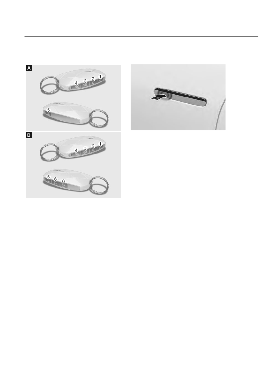
5-6
Convenience Features
Using Smart Key
ORS051003
ORS051003
ORS051004
ORS051004
Your Genesis Branded Vehicle uses a
Smart Key, which you can use to lock or
unlock the driver and passenger doors or
the rear trunk.
M Door lock
N Door unlock
O Trunk open
P Panic
Q Remote Start
R
Remote Smart Parking Assist
(Forward/Backward)
Locking your vehicle
ORS051005
ORS051005
To lock your vehicle using the door
handle touch sensor or the Smart Key:
1. Make sure all doors, the hood and the
trunk are closed.
2. Make sure you have the smart key in
your possession.
3. Touch the door lock/unlock sensor on
the door handle (the engraved part) or
press the Door Lock button M on the
smart key. The hazard warning lights
will blink.
• Make sure the doors are locked.
When doors lock, the handle
become flush to the body.
ACCESSING YOUR VEHICLE
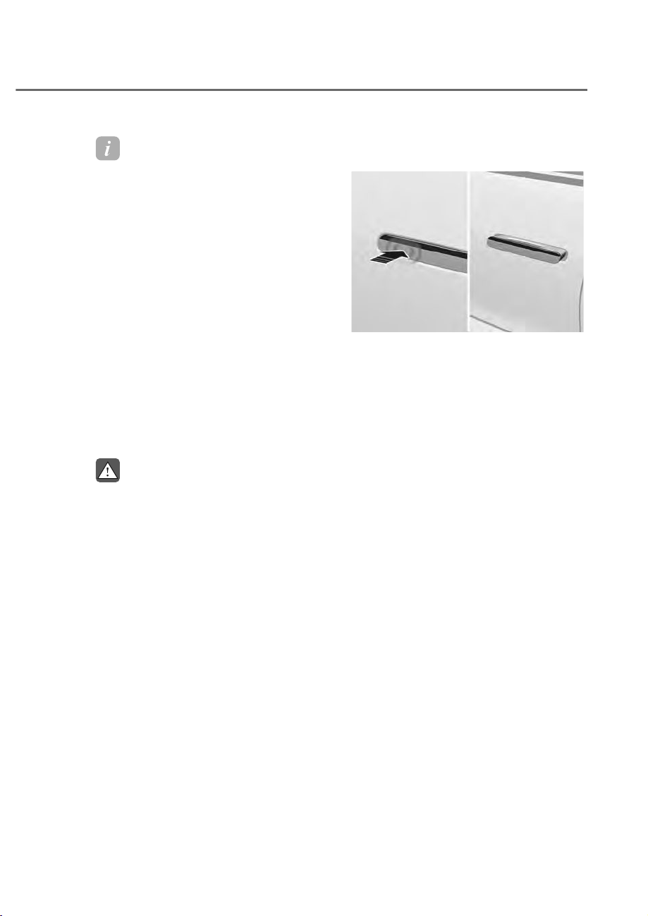
5-7
05
Information
• The side view mirror will fold if
‘Enable on Door Unlock’ is selected
from the Settings menu in the
infotainment system screen. Select:
- 6HWXSĺ9HKLFOHĺ&RQYHQLHQFHĺ
:HOFRPH0LUURU/LJKWĺ2QGRRU
unlock
• The door handle touch sensor will only
operate when the smart key is within
28~40 in. (0.7~1 m) from the outside
door handle.
• Note that you cannot lock your vehicle
using the door handle touch sensor if
any of the following occur:
- The Smart Key is in the vehicle.
- The Engine Start/Stop button is from
$&&RU21SRVLWLRQ
- Any of the doors are open except for
the trunk.
WARNING
Do not leave the Smart Key in your
vehicle with unsupervised children.
Unattended children could press the
Engine Start/Stop button and may
operate power windows, lock the doors
or other controls, or even make the
vehicle move, which could result in
serious injury or death.
Unlocking your vehicle (When the
Two Press Unlock feature is off)
ORS051006
ORS051006
To unlock your vehicle using the door
handle touch sensor or the Smart Key:
1. Make sure you have the smart key in
your possession.
2. Touch the door lock/unlock sensor on
the door handle (the engraved part)
or press the Door Unlock button N on
the smart key.
3. When all doors unlock, door handles
will pop out and the hazard warning
lights will blink two times.

5-8
Convenience Features
Unlocking your vehicle
(When the Two Press Unlock feature
is on)
To unlock your vehicle using the door
handle touch sensor or the Smart Key:
1. Make sure you have the smart key in
your possession.
2. Touch the door lock/unlock sensor on
the door handle (the engraved part)
or press the Door Unlock button N on
the smart key.
3. The driver’s door handle will pop out
and unlock.
4. If you touch the door lock/unlock
sensor on the door handle or press the
Door Unlock button N on the smart
key once more within 4 seconds, all
of the doors unlock. When the doors
unlock, door handles will pop out. The
hazard warning lights will blink two
times and the chime will sound.
5. After unlocking the doors, the doors
will automatically relock after 30
seconds unless a door is opened.
Setting the Two Press Unlock feature
The priority for unlocking the driver door
only, or unlocking all the doors with one
press may be adjusted in the Settings
menu in the infotainment system screen.
The Two Press Unlock feature, when
enabled, will require the user to press
the door unlock button once for driver
door only and twice for unlocking all the
doors.
6HWXSɌ9HKLFOHɌ'RRUɌȹ3UHVV8QORFN
Information
• If you press the front passenger outside
door handle with the smart key in your
possession, all the doors will unlock.
• The Two Press Unlock feature is off
when the vehicle is first delivered. To
use the feature, enable the feature from
the Settings menu in the infotainment
system screen.
Information
• The side view mirror will unfold if
µ2QGRRUXQORFN¶LVVHOHFWHGIURPWKH
Settings menu in the infotainment
system screen. Select:
- 6HWXSĺ9HKLFOHĺ&RQYHQLHQFHĺ
:HOFRPH0LUURU/LJKWĺ2QGRRU
unlock
• The door handle touch sensor will only
operate when the smart key is within
28~40 in. (0.7~1 m) from the outside
door handle.
• After unlocking the doors, the doors
will automatically relock after 30
seconds unless a door is opened.
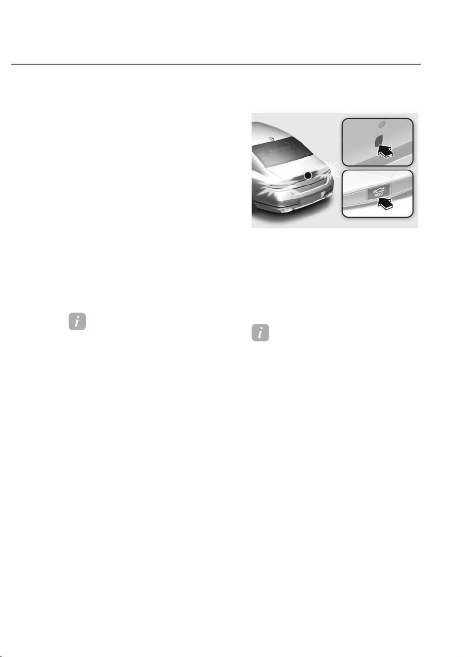
5-9
05
Setting the door lock/unlock prevention
feature
The doors may lock or unlock if the touch
sensor of the outside door handle is
recognized while washing your vehicle or
due to heavy rain.
To prevent unintentional door lock or
unlock:
Press the lock button on the smart key
and immediately press the unlock button
along with the lock button for more than
4 seconds. The hazard warning lights will
blink four times. At this time, the doors
will not lock or unlock even though the
touch sensor is touched on the outside
door handle.
To deactivate the function, press the
door lock or unlock button on the smart
key.
Information
• During a car wash or rain, in order
to minimize unintentional operation
of the touch sensor, the touch sensor
may become insensitive. This is not a
malfunction.
• The doors may not lock or unlock in
the following situations.
- If the touch sensor is touched with
gloves on
- If you suddenly approach the door
and touch the sensor
Opening the trunk
ORS051007
ORS051007
1. Make sure you have the smart key in
your possession.
2. Press either the trunk open button
on the vehicle or press and hold the
Trunk Open button O on the smart key
for more than one second. The hazard
warning lights will blink two times and
the trunk will open.
Information
• The trunk open button will only
operate when the smart key is within 28
in. (0.7 m) from the trunk.
• For more details on opening or closing
the trunk, refer to "Power Trunk"
section in this chapter.

5-10
Convenience Features
Panic button
Press and hold the Panic button P for
more than one second. The horn sounds
and hazard warning lights blink for about
30 seconds. To cancel the panic mode,
press any button on the Smart Key.
Remotely starting vehicle (if
equipped)
You can start the vehicle using the
Remote Start button Q on the smart key.
To start the vehicle remotely:
1. Press the door lock button on the
smart key within 32 feet (10 m) from
the vehicle.
2. Press the Remote Start button Q for
more than 2 seconds within 4 seconds
after pressing the door lock button.
The hazard warning lights will blink
and the engine will start.
3. To turn off the remote start function,
press the Remote Start button Q
once.
Information
• The vehicle must be in P (Park) for the
remote start function to start.
• The engine turns off if you get in the
vehicle without a registered smart key.
• The engine turns off if you do not get
in the vehicle within 10 minutes after
remotely starting the vehicle.
• The Remote Start button Q may not
operate if the smart key is not within 32
feet (10 m).
• The vehicle will not remotely start if the
engine hood or trunk is opened.
• Do not idle the engine for a long period.
• Do not operate remote start in closed
areas where there is no adequate
ventilation for the engine exhaust.
Remotely moving vehicle forward or
backward (if equipped)
With the smart key, the driver can move
the vehicle forward or backward using
the Forward/Backward button R on the
smart key.
For more details, refer to “Remote Smart
Parking Assist (RSPA)” section in chapter
7.
Start-up
You can start the engine without
inserting the key.
For more details, refer to the “Engine
Start/Stop Button” section in chapter 6.
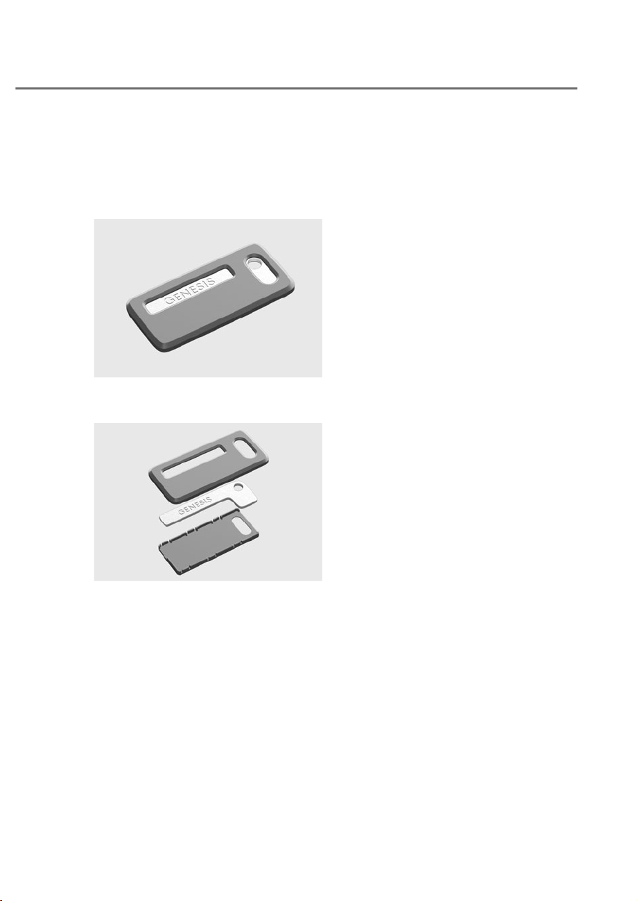
5-11
05
Using mechanical key
If the Smart Key does not operate
normally, you can lock or unlock the
driver’s door by using the mechanical
key.
OJWEV051097
OJWEV051097
1. Press the Genesis text section of the
Mechanical key to remove the case.
OJWEV051098
OJWEV051098
2. Remove the mechanical key from the
case.
3. After use, reinstall the mechanical key
in the reverse order of removal.
Loss of a smart key
A maximum of two Smart Keys can
be registered to a single vehicle. If
you happen to lose your smart key,
it is recommended that you should
immediately take the vehicle and
remaining keys to your authorized
retailer of Genesis Branded products or
tow the vehicle, if necessary.
Smart Key Precautions
• Avoid keeping a smart key with
accessories in the same location such
as pants or jacket pocket. The smart
key button may be pressed by the
accessory.
• The smart key may not work if any of
the following occur:
- The smart key is close to a radio
transmitter such as a radio station
or an airport which can interfere
with normal operation of the
transmitter.
- The smart key is near a mobile
two way radio system or a mobile
phone.
- Another vehicle’s smart key is being
operated close to your vehicle.
- Connecting an external device to
the power outlet and placing the
smart key near the external device.
• If your windows are tinted, especially
with metallic window tint, it may
cause frequency interference,
reducing the smart key operating
range.
If the smart key does not work correctly,
open and close the door with the
mechanical key, To start the engine,
press the Engine Start/Stop button
directly with the smart key. If you have
a problem with the smart key, it is
recommended to contact an authorized
retailer of Genesis Branded products.
If the smart key is in close proximity to
your mobile phone, the signal could be
blocked by your mobile phone’s normal
operational signals. This is specifically
relevant when the phone is active such
as making and receiving calls, text
messaging, and/or sending/receiving
emails. When possible, avoid keeping
the smart key and your mobile phone in
the same location such as pants or jacket
pocket in order to avoid interference
between the two devices.

5-12
Convenience Features
Information
If the smart key is not moved for some
time, the detection function for smart key
operation will pause. Lift the smart key to
activate the detection again.
NOTICE
To prevent damaging the smart key:
• Keep the smart key in a cool,
dry place to avoid damage or
malfunction. Exposure to moisture
or high temperature may cause
the internal circuit of the smart key
to malfunction which may not be
covered under warranty.
• Avoid dropping or throwing the
smart key.
• Protect the smart key from extreme
temperatures.
NOTICE
• Keep the smart key away from
electromagnetic materials that
blocks electromagnetic waves to the
key surface.
• Always have the smart key with
you when leaving the vehicle. If the
smart key is left near the vehicle, the
vehicle battery may be discharged.
Information
This device complies with Part 15 of the
)&&UXOHV
2SHUDWLRQLVVXEMHFWWRWKHIROORZLQJWKUHH
conditions:
1. This device may not cause harmful
interference, and
2. This device must accept any
interference received, including
interference that may cause undesired
operation.
3. &KDQJHVRUPRGLILFDWLRQVQRWH[SUHVVO\
approved by the party responsible
for compliance could void the user’s
authority to operate the device.
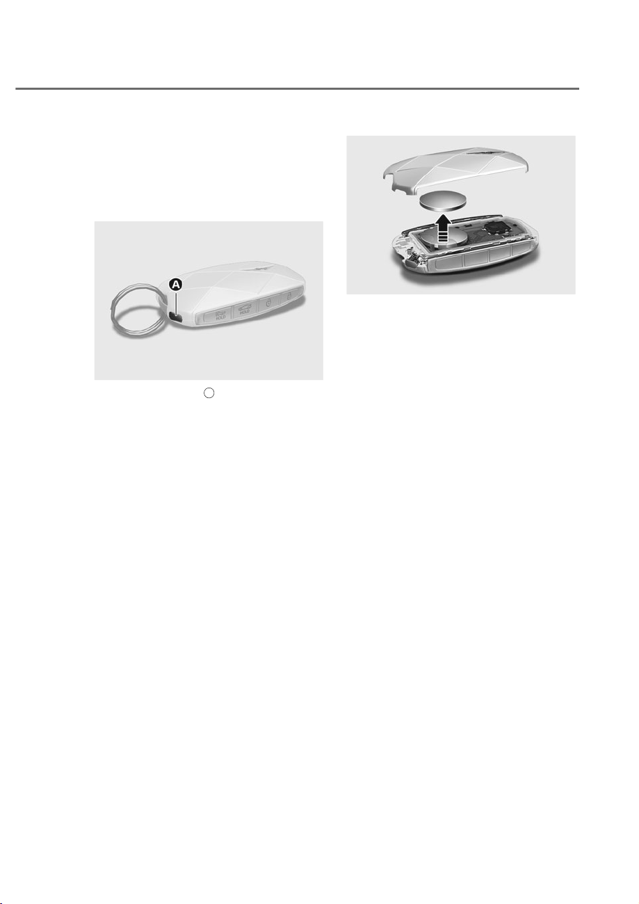
5-13
05
Replacing the Battery
If the Smart Key is not working properly,
try replacing the battery with a new one.
Battery Type: CR2032
To replace the battery:
ORS051008
ORS051008
1. Press the button
A
to remove the
keyring fixed appliance.
2. Insert a phillips screwdriver into the
inner groove to remove the battery
cover.
OJWEV051237
OJWEV051237
3. Remove battery cover using a phillips
screwdriver.
4. Remove the old battery and insert the
new battery. Make sure the battery
position is correct.
5. Reinstall the battery cover and smart
key cover in the reverse order of
removal.
If you suspect your smart key might have
sustained some damage, or you feel
your smart key is not working correctly,
it is recommended that you contact an
authorized retailer of Genesis Branded
products.

5-14
Convenience Features
WARNING
THIS PRODUCT CONTAINS A BUTTON
BATTERY.
If swallowed, a lithium button battery
can cause severe or fatal injuries within
2 hours. Keep batteries out of reach of
children.
If you think batteries may have been
swallowed or placed inside any part
of the body, seek immediate medical
attention.
Information
An inappropriately disposed
battery can be harmful to
the environment and human
health. Dispose of the battery
according to your local law(s) or
regulations.
Immobilizer System
The immobilizer system protects your
vehicle from theft. If an improperly
coded key (or other device) is used, the
engine’s fuel system is disabled.
When the Engine Start/Stop button
is pressed to the ON position, the
immobilizer system indicator should
come on briefly, then go off. If the
indicator starts to blink, the system does
not recognize the coding of the key.
Press the Engine Start/Stop button to
the OFF position, then press the Engine
Start/Stop button to the ON position
again.
In some circumstances, the vehicle may
not recognize your smart key if another
smart key device is nearby or a metal
object such as a key chain is causing
interference with the smart key.
If this occurs, your vehicle may not
start. Remove any metal objects or
additional keys near the smart key before
attempting to start the vehicle again.
If the system repeatedly does not
recognize the coding of the key, it is
recommended that you contact your
retailer of Genesis Branded products.
Do not attempt to alter this system
or add other devices to it. Electrical
problems could result that may make
your vehicle inoperable.

5-15
05
WARNING
In order to prevent theft of your
vehicle, do not leave spare keys
anywhere in your vehicle. Your
immobilizer password is a customer
unique password and should be kept
confidential.
NOTICE
The transponder in your key is an
important part of the immobilizer
system. It is designed to give years
of trouble-free service, however you
should avoid exposure to moisture,
static electricity and rough handling.
Immobilizer system malfunction could
occur.
Information
This device complies with Part 15 of the
)&&UXOHV
2SHUDWLRQLVVXEMHFWWRWKHIROORZLQJWKUHH
conditions:
1. This device may not cause harmful
interference.
2. This device must accept any
interference received, including
interference that may cause undesired
operation.
3. &KDQJHVRUPRGLILFDWLRQVQRWH[SUHVVO\
approved by the party responsible
for compliance could void the user’s
authority to operate the device
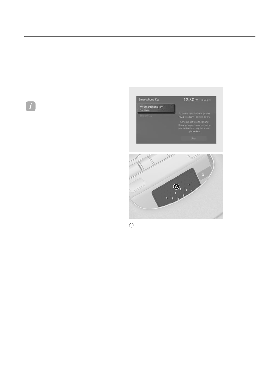
5-16
Convenience Features
Genesis digital key provides convenience
to the driver, which the driver can use to
lock or unlock the driver and passenger
doors or the trunk and turn on the
vehicle.
Digital Key (Smart Phone)
Information
• Genesis digital key is only available for
smart phones that support the digital
key feature, provided by the smart
phone manufacturer.
• The driver can confirm supported/
compatible devices on our website
(https://owners.genesis.com).
• &HUWDLQIXQFWLRQVPD\QRWRSHUDWH
depending on whether the service is
provided in the vehicle.
• During the digital key system
update, the smart key may not work
temporarily.
Setting your smart phone
To use the digital key (smart phone),
download the Genesis Intelligent
Assistant App and sign up for a Genesis
account and service.
Registering your digital key (smart
phone)
1. Turn on the vehicle with a smart key.
Have your smart key with you in the
vehicle.
ORS052311N
ORS052311N
ORS051066
ORS051066
A
: Vehicle authentication pad (Wireless charging pad)
2. From the infotainment system
6HWWLQJVPHQXVHOHFWȁ6HWXSɌ9HKLFOH
Ɍ'LJLWDO.H\Ɍ6PDUWSKRQH.H\Ɍ0\
Smartphone Key’.
3. $IWHUVHOHFWLQJȁ'LJLWDO.H\Ɍ6HW
Up Digital Key’ from the Genesis
Intelligent Assistant App in the
smart phone, register the digital key
according to the guidance in the
smart phone screen.
• Ultra Wide Band unsupported smart
phone
- Place your smart phone on
the vehicle authentication pad
(wireless charging pad) with the
screen facing up.
*(1(6,6',*,7$/.(<ʚ,)(48,33('ʛ

5-17
05
• Ultra Wide Band supported smart
phone
- The digital key can be registered
if the smart phone is inside the
vehicle even without placing it
on the vehicle authentication pad
(wireless charging pad).
4. Press the ‘Save’ button from the
infotainment system screen. The
saving process begins automatically.
• When the digital key (smart phone)
is saved, a message appears on the
infotainment system screen.
Information
• If you want to register a digital key
(smart phone) again, refer to ‘How to
Delete Digital Key (Smart Phone)’ and
delete the digital key (smart phone)
before re-registering.
• During the digital key saving process,
the process will cancel when:
- The smart phone is removed from the
vehicle authentication pad (wireless
charging pad)
- The infotainment system screen is
changed
- The vehicle is turned off
- The gear is shifted
• The registering process does not start if
a smart key is not in the vehicle.
• Some smart phones may not start the
registering process depending on the
internal structure. Move the smart
phone to the left or right on the vehicle
authentication pad (wireless charger
pad) and try registering the smart
phone.
Using the digital key (smart phone)
Digital key touch control
The driver can lock or unlock the door by
placing the smart phone on the outside
door handle, and the vehicle can be
started by placing the smart phone on
the vehicle authentication pad (wireless
charging pad).
Digital key close proximity control
• If you have the smart phone in
possession, the doors can be locked
or unlocked without touching the
smart phone to the door handle, but
by touching the door lock/unlock
sensor (engraved part) on the door
handle. Also, the vehicle can be
started by pressing the Engine Start/
Stop button without placing the smart
phone on the vehicle authentication
pad (wireless charging pad).
• When the smart phone and vehicle is
connected by Bluetooth, the Remote
Start, Door Lock/Unlock, and Panic
functions are available using the
App provided by the smart phone
manufacturer.
Information
• The function is only available for Ultra
Wide Ban supported smart phone
digital keys. To use the function, the
smart phone’s Bluetooth must be
activated.
• The necessary distance between the
smart phone and vehicle for Bluetooth
connection may vary depending on the
surroundings of the vehicle and smart
phone.
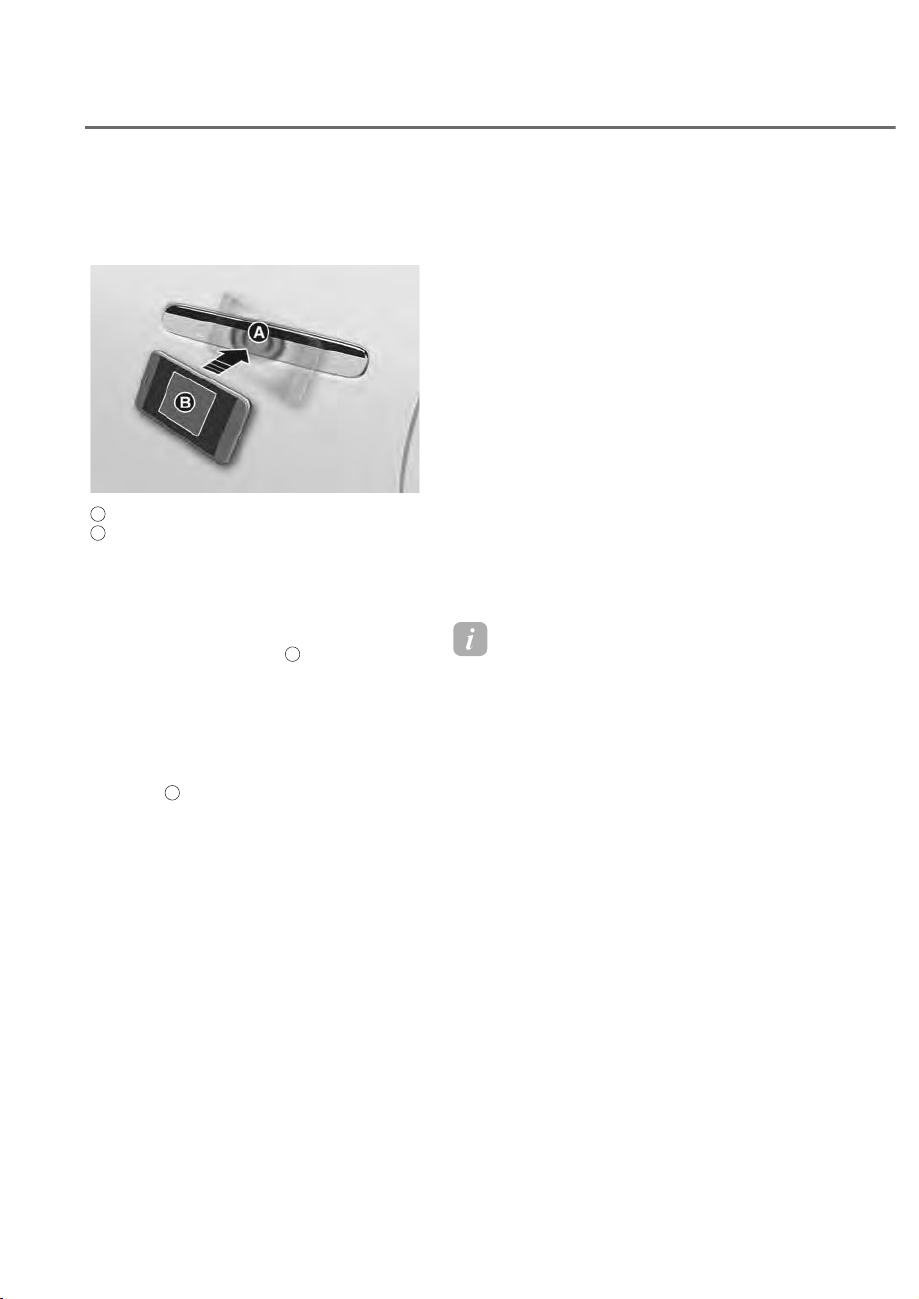
5-18
Convenience Features
Lock/Unlocking the doors
• Ultra Wide Band unsupported smart
phone
ORS051009
ORS051009
A
: Door handle authentication pad
B
: NFC antenna (Backside of the smart phone) (The
antenna position differs depending on models.)
- The door will lock or unlock by
touching the registered digital
key (card key) NFC antenna to the
driver’s or passenger’s door handle
authentication pad
A
for more than
2 seconds.
- If the Two Press Unlock feature
is set, only the driver’s door pops
out and unlocks when the digital
key (smart phone) is placed on the
driver’s door handle authentication
pad
A
. Place the digital key (smart
phone) on the driver’s door handle
authentication pad once more
within 4 seconds to unlock all doors.
• Ultra Wide Band supported smart
phone
- If you touch the door lock/unlock
sensor (engraved part) on the
door handle with the smart phone
in possession, the door locks or
unlocks.
- If you approach the front door
handle with the smart phone
in possession when ‘On driver
approach’ is set, the door unlocks
automatically.
• After unlocking the doors, the doors
will automatically re-lock after 30
seconds unless a door is opened.
• If the smart phone digital key does
not operate, try again after moving
the smart phone away from the door
handle authentication pad (more than
4 in. (0.1 m)).
Information
• You cannot lock your vehicle using the
digital key (smart phone) if any of the
following occurs:
- The smart key is in the vehicle.
- The Engine Start/Stop button is in
WKH$&&RU21SRVLWLRQ
- Any of the doors, hood, or trunk are
open.
• The door may not unlock automatically
if you stay near the vehicle for several
minutes with the Ultra Wide Band
supported smart phone in possession.
• If the smart phone is kept in the back
pocket or bag, it may cause poor
Bluetooth connection, or the door lock/
unlock or vehicle start-up operation my
be delayed.

5-19
05
Starting the vehicle
• Ultra Wide Band unsupported smart
phone
- After placing your registered digital
key (smart phone) on the vehicle
authentication pad (wireless
charging pad), depress the brake
pedal and press the Engine Start/
Stop button.
• Ultra Wide Band supported smart
phone
- With the smart phone inside the
vehicle, depress the brake pedal
and press the Engine Start/Stop
button.
- To start the vehicle remotely, use
the App provided by the smart
phone manufacturer to lock the
vehicle with the door lock button,
and press the remote start button
within 4 seconds.
The vehicle starts and the hazard
warning lights blink.
- Press the remote start button again
to turn off the vehicle.
After starting the vehicle, the digital key
(smart phone ) may be removed from
the vehicle authentication pad (wireless
charging pad).
Information
If a shared digital key (smart phone) is
used for the first time, the activating time
may take longer.
• Place the shared digital key
(smart phone) on the door handle
authentication pad until the vehicle
door lock/unlock activates.
• If a shared digital key (smart phone) is
first used on the vehicle authentication
pad (wireless charger pad), the initial
start of the vehicle may fail.
• If the door lock/unlock is activated
once with the shared digital key (smart
phone) or the vehicle is started with
the digital key (smart phone) on the
vehicle authentication pad, the digital
key (smart phone) will be registered in
the vehicle.
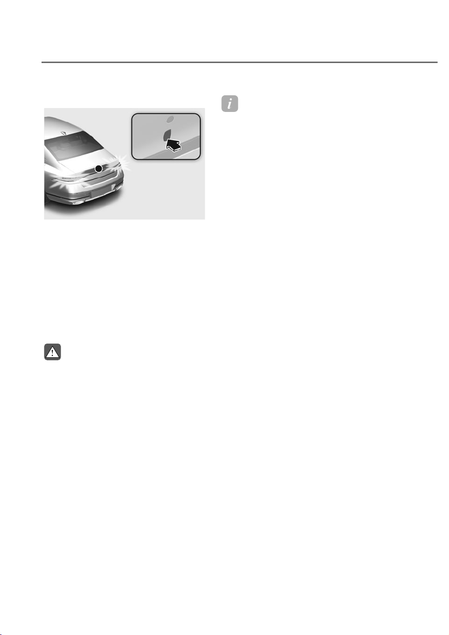
5-20
Convenience Features
2SHUDWLQJWKHSRZHUWUXQN
ORS052007N
ORS052007N
• Ultra Wide Band supported smart
phone
If the vehicle is locked, press the
power trunk open button with the
smart phone in possession to open
the trunk.
If you are in the detecting area behind
the trunk for more than 3 seconds
with the smart phone in possession
when ‘Smart Trunk' is set, the trunk
opens automatically.
WARNING
The vehicle can be started when the
registered smart phone is in the vehicle.
Therefore, do not leave unsupervised
children or people who are not aware of
the system since it can result in serious
injury or death. In addition, always have
the registered smart phone with you to
prevent vehicle theft when leaving the
vehicle.
Information
• The Ultra Wide Band supported smart
phone digital key can be used only
when the smart phone and vehicle are
connected with Bluetooth.
- The necessary distance between
the smart phone and vehicle for
Bluetooth connection may vary
depending on the surroundings.
- Window tinting substances may
cause poor Bluetooth connection.
- If the smart phone is kept in the
back pocket or bag, it may cause
poor Bluetooth connection, or the
door lock/unlock or vehicle start-up
operation my be delayed.
• The Ultra Wide Band supported smart
phone digital key can be used only for
a certain amount of time to optimize
the performance of the smart phone
and vehicle battery. If you stay near
the vehicle for several minutes with
the Ultra Wide Band supported smart
phone, the Auto Unlock feature may
not operate.
• &KHFNWKHVPDUWSKRQH¶VVHWWLQJPHQX
or the App provided by the smart
phone manufacturer for connection of
the vehicle and smart phone.
• The Ultra Wide Band supported smart
SKRQHGLJLWDONH\FDQDOVRXVHWKH1)&
function.

5-21
05
Deleting your digital key (smart
phone)
Turn on the vehicle with a smart key.
Have your smart key with you in the
vehicle.
ORS052330N
ORS052330N
Deleting all registered digital key (smart
phone)
To delete all the registered digital key
(smart phone), from the Settings menu
VHOHFWȁ6HWXSɌ9HKLFOHɌ'LJLWDO.H\
Ɍ6PDUWSKRQH.H\Ɍ'HOHWH$OOȂLQWKH
infotainment system.
• The ‘Delete All’ button is disabled
if there is no registered digital key
(smart key).
ORS052312N
ORS052312N
Deleting my registered digital key (smart
phone)
To delete only my registered digital key
(smart phone), from the Settings menu
VHOHFWȁ6HWXSɌ9HKLFOHɌ'LJLWDO.H\Ɍ
6PDUWSKRQH.H\Ɍ0\6PDUWSKRQH.H\Ɍ
Delete’ in the infotainment system.
• If a shared digital key (smart phone) is
registered, it cannot be deleted.
• A new smart phone can be registered
after deleting the existing digital key
(smart phone) from ‘My Smartphone
Key’ menu.
Information
• If the registered digital key (smart key)
is deleted, the digital key saved in the
smart phone will also be deleted.
• If the digital key is deleted from the
smart phone, the digital key (smart
phone) registered in the vehicle will also
be deleted.
• The shared digital key registered in the
vehicle cannot be deleted individually.
• (YHQWKRXJKWKH*HQHVLV&RQQHFWHG
Services App is deleted from the smart
phone, the digital key saved in the
smart phone will not be deleted.
• Management of the digital key saved
in the smart phone is available from
the App provided by the smart phone
manufacturer.
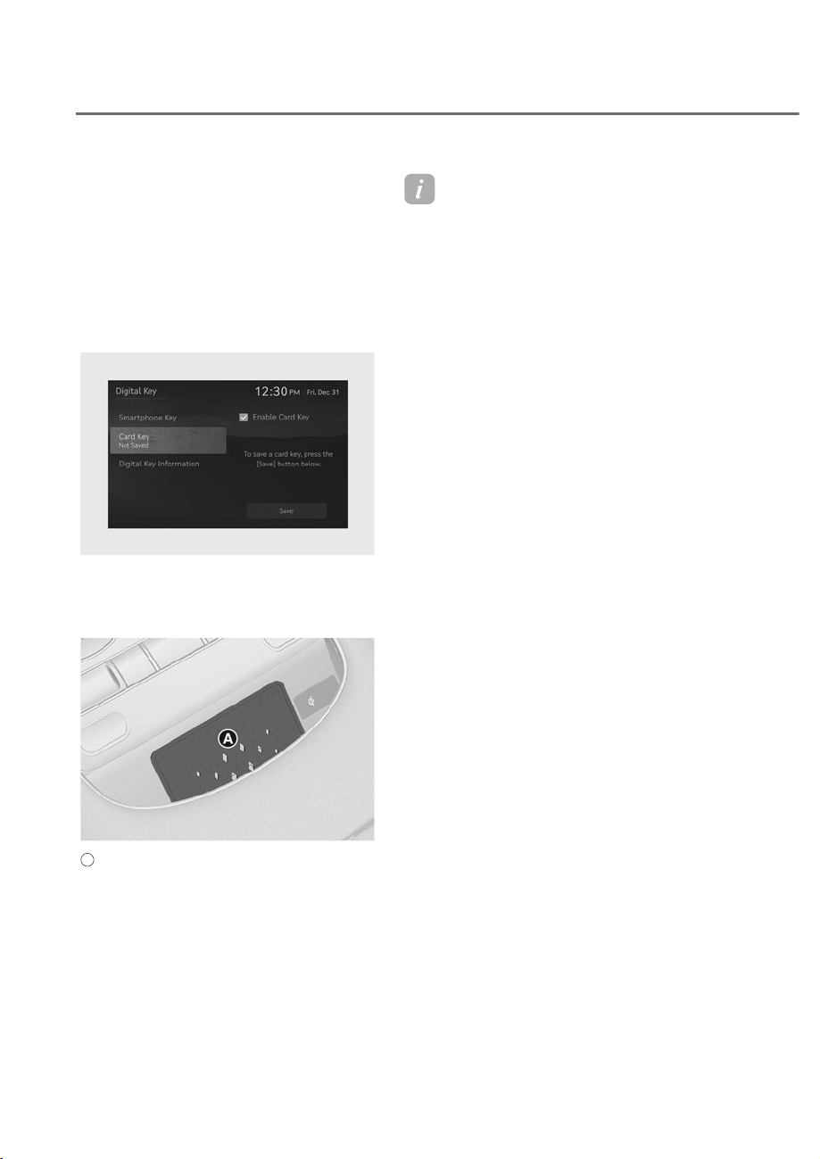
5-22
Convenience Features
Digital Key (Card Key)
(if equipped)
To use the card key as a digital key,
follow the following procedure.
Registering your digital key (card
key)
1. Have both of your smart keys with you
in the vehicle.
OJWEV051290N
OJWEV051290N
2. 6HOHFWȁ6HWXSɌ9HKLFOHɌ'LJLWDO.H\
Ɍ&DUG.H\ȂIURPWKH6HWWLQJVPHQX
and check whether ‘Enabled Cark Key’
is selected in the infotainment system.
ORS051066
ORS051066
A
: Vehicle authentication pad (Wireless charging pad)
3. Place your card key on the vehicle
authentication pad (wireless charging
pad) while the vehicle is on.
4. Register your card key by selecting
ȁ6HWXSɌ9HKLFOHɌ'LJLWDO.H\Ɍ&DUG
.H\Ɍ6DYHȂIURPWKH6HWWLQJVPHQXLQ
the infotainment system.
Information
• When there is a digital key (card key)
already registered in the vehicle, a
new digital key (card key) cannot be
registered. Re-register a new digital
key (card key) after deleting the exiting
digital key (card key).
• To register a digital key (card key),
both of your smart keys must be in the
vehicle.
• A registered digital key (card key)
cannot be registered in other vehicles.
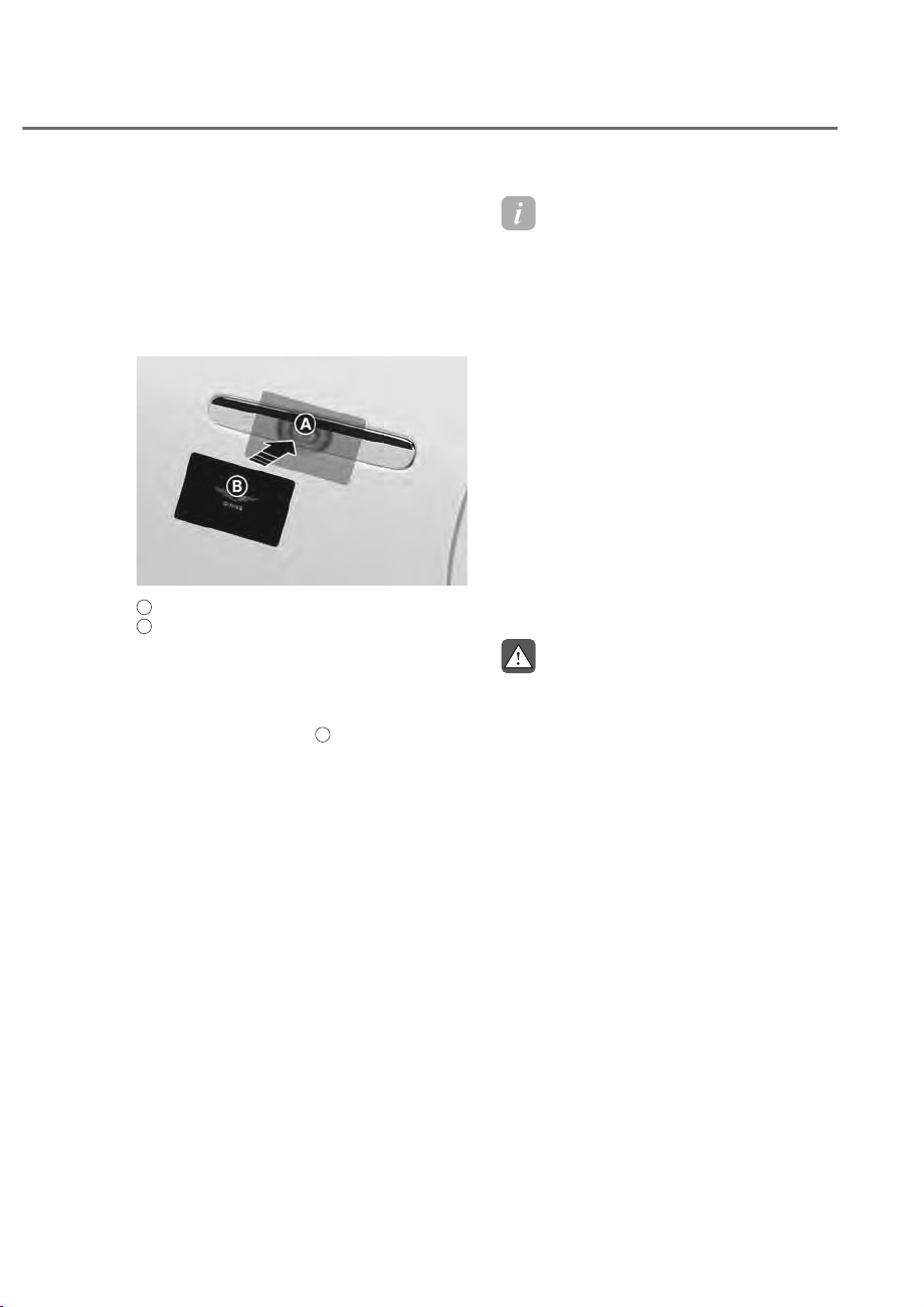
5-23
05
Using the digital key (card key)
The driver can lock or unlock the door by
placing the card key on the outside door
handle, and the vehicle can be started
by placing the card key on the vehicle
authentication pad (wireless charging
pad).
ORS052259N
ORS052259N
A
: Door handle authentication pad,
B
: Card key NFC antenna
Locking/Unlocking the doors
• If the driver places the digital
key (card key) on the driver’s
or passenger’s door handle
authentication pad
A
for more than 2
seconds, the door will lock or unlock.
• If the Two Press Unlock feature is set,
only the driver’s door pops out and
unlocks when the digital key (card key)
is placed on the driver’s door handle
authentication pad. Hold the digital
key (card key) near the driver’s door
handle authentication pad once more
within 4 seconds to unlock all doors.
• After unlocking the doors, the doors
will automatically re-lock after 30
seconds unless a door is opened.
Information
You cannot lock your vehicle using
the digital key (card key) if any of the
following occurs:
- The smart key is in the vehicle.
- The Engine Start/Stop button is in the
$&&RU21SRVLWLRQ
- Any of the doors, hood, or trunk are
open.
Starting the vehicle
After placing your registered digital key
(card key) on the vehicle authentication
pad (wireless charging pad), depress the
brake pedal and press the Engine Start/
Stop button.
For more details on the basic way to
start the vehicle, refer to “Engine Start/
Stop Button” section in chapter 6.
WARNING
The vehicle can be started when the
registered card key is placed on the
vehicle authentication pad (wireless
charging pad). Therefore, do not leave
unsupervised children or people who
are not aware of the system since it
can result in serious injury or death. In
addition, always have the registered
card key with you to prevent vehicle
theft when leaving the vehicle.

5-24
Convenience Features
NOTICE
• The digital key (card key) may not
work under the following conditions:
- The digital key (card key) is not
placed on the center of the
door handle authentication pad
or vehicle authentication pad
(wireless charging pad) correctly.
- The digital key (card key) is near
1)&HQDEOHGFDUGVVXFKDVFUHGLW
cards or smart phones.
- If the digital key (card key) does not
work, try again after moving the
digital key (card key) away from the
door handle authentication pad
(more than 4 in. (0.1 m)).
• The digital key (card key) can be
damaged by impacts. If the digital
key (card key) is damaged, replace
the digital key (card key) with a new
one and register it again.
• Long-time exposure to high
temperature may cause the digital
key (card key) to malfunction. Be
careful not to expose the digital key
(card key) to direct sunlight or high
temperature.
Deleting your digital key (card key)
1. Turn on the vehicle with a smart key.
Have your smart key with you in the
vehicle.
OJWEV051291N
OJWEV051291N
2. From the infotainment system settings
PHQXVHOHFWȁ6HWXSɌ9HKLFOHɌ'LJLWDO
.H\Ɍ&DUG.H\Ɍ'HOHWHȂ
• The ‘Delete’ button is disabled if
there is no digital key (card key)
registered.

5-25
05
Personalized Profile and Vehicle
Settings
You can set the registered digital key
(smart phone) profiles for Driver 1 and
Driver 2. When you use the digital key
(smart phone), the vehicle can be set
to the user-defined personalized profile
(includes items such as vehicle settings
and audio preferences).
Linking / Unlinking profile
How to link user profile
1. 6HOHFWȁ6HWXSɌ8VHU3URILOHɌ
3URILOH6HWWLQJVɌ/LQN'LJLWDO.H\
(Smartphone)’ from the Settings menu
in the infotainment system.
2. Select ‘Link’ to connect the registered
smart phone’s digital key and the
user’s profile.
3. Follow the instructions according
to the message on the infotainment
system screen.
How to unlink user profile
6HOHFWȁ6HWXSɌ8VHU3URILOHɌ3URILOH
Settings’, and then deselect ‘Link Digital
Key (Smartphone)’ from Settings menu in
the infotainment system.
• Unlinking is possible only when user
profile is linked.
Information
• User profile cannot be linked to
both Driver 1 and Driver 2 that are
connected to a single smart phone.
Personalization will operate with the
recently linked user profile, and the
previously linked user profile will be
automatically canceled.
• User profile link works only when the
digital key is registered to the vehicle.
• 'LJLWDONH\&DUGNH\FDQQRWEHOLQNHG
with a user profile.
• If the user profile linked digital key
in the smart phone is deleted, the
digital key should be re-registered and
personalized by linking the user profile
again.

5-26
Convenience Features
Vehicle personalization operation
• The personalization function linked
with digital key works when the profile
linked smart phone is placed on the
outside door handle authentication
pad to lock or unlock the doors.
The profile set by the digital key
can be changed manually from the
infotainment system.
• The personalization function using
the digital key can be operated
after linking the digital key in the
infotainment system profile menu.
• The personalization function works
only when the vehicle is OFF or when
the vehicle is started remotely. If the
vehicle is not started remotely, the
personalization function does not
work with the digital key.
Information
User profile operation according to door
lock/unlock system is as follows:
Item
Personalization
operation
Initial value Guest
Profile linked smart
phone key
Linked profile
Profile unlinked
smart phone key
Recently activated
profileNFC card key
Smart key

5-27
05
Vehicle personalization with digital key
The available personalization function in the vehicle is as follows:
System Personalization Item
Infotainment
system vehicle
settings
Head Up Display (HUD)
Position adjustment of image, Information
display selection
Lamp Blink number of one-touch signal lamps
Cluster
Information display on the cluster, Voice
volume, Welcome sound
Seat/Mirror/Steering
wheel
Seat position, O/S mirror position, Steering
wheel position, Easy Access
Smart heating wire/ventilation On/Off
Door Automatic door lock/unlock, Two Press Unlock
Smart phone wireless
charging
Wireless charging On/Off
Air conditioning
Setting up temperature unit, Block air inflow/
Automatic ventilation/Window defroster On/
Off
Infotainment
menu
Navigation
Preferred volume of the navigation system
Recent destination
User preset My menu list settings, Radio preset
Phone connectivity
Bluetooth preferential connection
CarPlay/Android Auto/MirrorLink On/Off
Air conditioning Operating condition
Latest operation setup of the following
functions: Temperature (AUTO), air flow
direction, air volume, air conditioner, air intake
control, SYNC, Front windshield defroster,
OFF
For more information of personalization, refer to the infotainment system manual.
CAUTION
If you leave the digital key in the vehicle after locking or unlocking the doors or
starting the vehicle with the smart key, the doors can be locked with the central
door lock. Have the digital key with you at all times.

5-28
Convenience Features
Used Vehicle/Digital Key
Maintenance
Purchasing used vehicle
If any of the digital key devices (smart
phone key, card key) are registered in
the vehicle, the ‘Digital key registered’
message appears once on the instrument
cluster when the Engine Start/Stop
button is in the ON position after
unlocking the doors. When purchasing
a used vehicle, be sure to check the
message and delete the smart phone key
and card key registered by the previous
user and inform the purchase of a used
vehicle through Genesis Customer Care.
If the card key comes with the vehicle,
check whether it operates properly.
Digital Key Maintenance
If you need to have your Digital Key
System repaired or replaced, the
registered smartphone key or card key
can be deleted.
Limitations of the System
• Genesis digital key may not operate if
any of the following occurs:
- The smart phone battery or the
vehicle battery is discharged
- NFC or Bluetooth is turned off in the
smart phone settings
- A credit card is near your smart
phone, or a metal or thick smart
phone case is used
- The card key is near other cards, or
used in a wallet or card holder
- There is electronic interference by
other vehicles, objects, etc.
• The vehicle may not be controlled
by the smart phone if any of the
following occurs:
- The basic necessary functions of the
smart phone are operating (general
call, urgent call, audio, etc.)
- Using a wireless earphone (general
call, urgent call, audio, etc.)
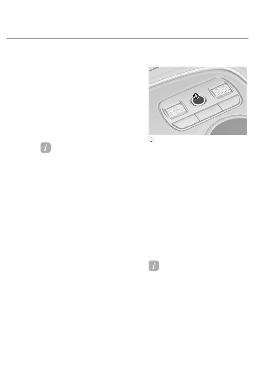
5-29
05
),1*(535,17$87+(17,&$7,216<67(0ʚ,)(48,33('ʛ
Fingerprint Authentication system
provides convenient features such as
allowing the driver to have access to
personal information, unlock profile
and exit valet mode with a registered
fingerprint.
A fingerprint must be registered in
the User Profile Settings from the
infotainment system to use the system.
The maximum of two fingerprints can
be registered. Driver 1 and Driver 2 can
register one fingerprint each.
Information
If no fingerprint is registered in the
infotainment system, Fingerprint
Authentication system does not operate.
)LQJHUSULQW$XWKHQWLFDWLRQ
System Settings
You can set or delete a fingerprint
through the infotainment system.
Follow the following procedure.
Registering fingerprint
ORS051012
ORS051012
A
: Fingerprint sensor
1. Have both of your smart keys with you
in the vehicle.
2. Turn on the engine and select ‘Setup
Ɍ8VHU3URILOHɌ'ULYHUȸɌ)LQJHUSULQW
Identification’ from the infotainment
system.
3. After entering the profile password,
VHOHFWȁ6HW'HOHWH)LQJHUSULQWɌ6HWȂ
4. Place your finger that you wish to
register on the fingerprint sensor
according to the instruction.
5. Following the instructions, place
several parts of your fingerprint until
the scanning process is complete.
When scanning is complete, the
”Saving fingerprint….” appears and
the fingerprint registering process is
proceeded.
Information
• Remove all substances including
protection film on the fingerprint
sensor, and then register your
fingerprint.
• The fingerprint registering process is
canceled when the following condition
occurs:
- The infotainment system screen is
altered
- The Engine Start/Stop button turns
on or off
- The gear is shifted, and the vehicle is
driven
5-30
Convenience Features
Deleting fingerprint
1. Have one of your smart key with you
in the vehicle.
2. 7XUQRQWKHDQGVHOHFWȁ6HWXSɌ
8VHU3URILOHɌ'ULYHUȸɌ)LQJHUSULQW
Identification’ from the infotainment
system.
3. After entering the profile password,
VHOHFWȁ6HW'HOHWH)LQJHUSULQWɌ
Delete’.
4. Delete the registered fingerprint
according to the message “Delete all
Driver 1 fingerprints?”.
CAUTION
Do not participate in duplicating your
fingerprint with anyone.
)LQJHUSULQW$XWKHQWLFDWLRQ
System Operation
Using features with touch control
The convenience features such as
personal information access, profile
unlock, and valet mode exit are available
with the Fingerprint Authentication
system.
When the fingerprint shape appears
on the infotainment system screen,
you should place your finger on the
fingerprint sensor in the vehicle
according to the instruction message for
authorization and then you can operate
the linked features without entering the
password.
If the Fingerprint Authentication system
does not work, pull your finger away
from the fingerprint sensor and then try
again.
Fingerprint linked features can be turned
on or off from the Settings menu. Select:
• ȁ6HWXSɌ8VHU3URILOHɌ'ULYHUȸRU
'ULYHUȹɌ)LQJHUSULQW,GHQWLILFDWLRQ
)LQJHUSULQWOLQNHG
features
Characteristic
Personal
information access
Use with a
fingerprint without
a password
Profile unlock
Valet mode exit
See additional information in supplied
Infotainment Manual.
Information
The same fingerprint cannot be
registered for Driver 1 and Driver 2. The
personalization function works with the
recently linked profile, and the previously
linked profile is automatically canceled.

5-31
05
Limitations of the System
• Fingerprint Authentication system
may not work when:
- Fingerprint authentication is
performed with an unregistered
fingerprint.
- The fingerprint is not placed on the
center of the fingerprint sensor.
- The fingerprint sensor or fingerprint
is wet or dirty.
- The film on the sensor is not
removed.
- The registered fingerprint is
wounded or swollen.
- The hand is overly dry.
- The sensor is touched shortly.
• If fingerprint authentication fails
repeatedly, fingerprint recognition is
temporarily restricted. You should try
it later or try other methods such as
inputting your password.
• All registered fingerprints may
be deleted during repair due to
a malfunction of the fingerprint
authentication system or related
parts. Have your smart key when you
visit an authorized retailer of Genesis
Branded products.
• You cannot use the fingerprint sensor
when the vehicle is discharged.
• Gently place your finger on the
fingerprint sensor. Fingerprint
authentication attempts with
excessive force may fail.
WARNING
Do not register children’s fingerprints in
the vehicle.
If you register children’s fingerprints
and leave them in the vehicle,
unexpected accidents may occur.
When purchasing a used vehicle
If you purchase a used vehicle, you
should confirm and delete all of the
registered fingerprints in Driver 1 and
Driver 2 profile.
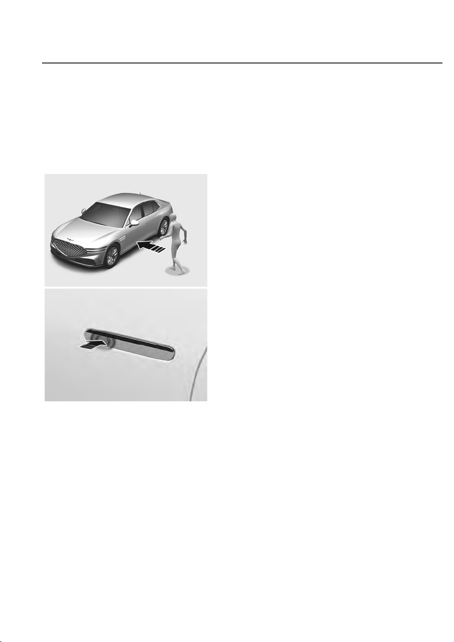
5-32
Convenience Features
Operating Door Locks from
Outside the Vehicle
Using smart key
To lock or unlock the doors from outside
the vehicle with the smart key button,
refer to the “Smart Key” section in
chapter 5.
ORS051015
ORS051015
ORS051005
ORS051005
:KHQµ2QGULYHUDSSURDFK¶LVVHW
1. Approach within 40 in. (1 m) to the
front outside door handle while
carrying the smart key.
- Outside door handles of all doors
pop out.
- The hazard warning lights blink two
times and all doors unlock.
• Approaching the driver’s door with
‘Two Press Unlock’ set
1. Approach the driver’s outside door
handle while carrying the smart key.
- Only the outside door handle of
the driver’s door pops out and
unlocks.
2. With door handle popped out,
touch the sensor (engraved part)
on the outside door handle within 4
seconds.
- Outside door handles of all doors
pop out and unlock.
• Approaching the front passenger’s
door with ‘Two Press Unlock’ set
1. Approach the front passenger’s
outside door handle while carrying
the smart key.
- The doors do not unlock.
2. Touch the door lock/unlock sensor
(engraved part) on the outside door
handle.
- Outside door handles of all doors
pop out and unlock.
DOOR LOCKS
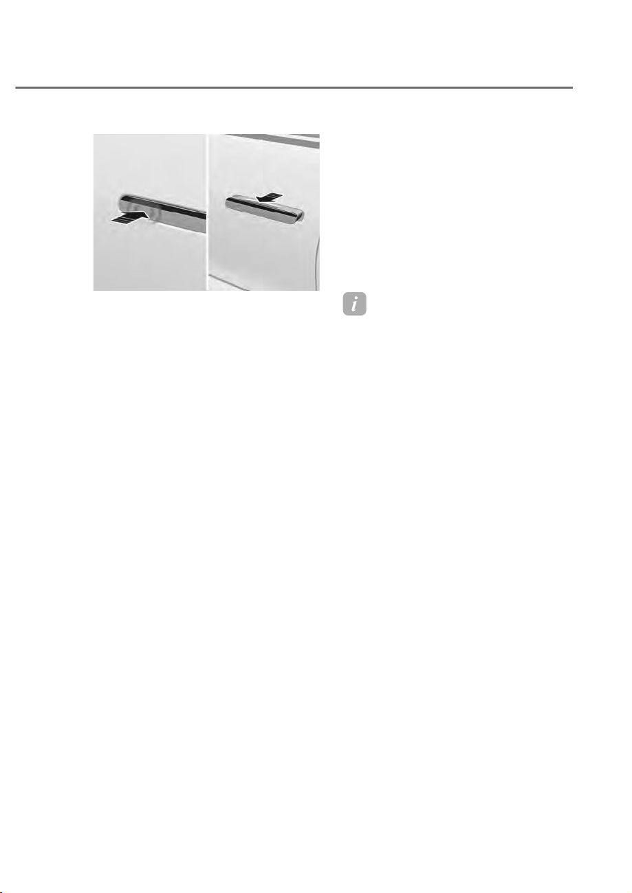
5-33
05
ORS051017
ORS051017
:KHQµ2QGULYHUDSSURDFK¶LVQRWVHW
1. Touch the front door lock/unlock
sensor (engraved part) on the driver’s
outside door handle.
- Outside door handles of all doors
pop out.
- The hazard warning lights blink two
times and all doors unlock.
• Approaching the driver’s door with
‘Two Press Unlock’ set
1. Touch the door lock/unlock sensor
(engraved part) on the driver’s
outside door handle.
- Only the outside door handle of
the driver’s door pops out and
unlocks.
2. With door handle popped out,
touch the sensor (engraved part)
on the outside door handle within 4
seconds.
- Outside door handles of all doors
pop out and unlock.
• Approaching the front passenger’s
door with ‘Two Press Unlock’ set
1. Touch the door lock/unlock sensor
(engraved part) on the front
passenger’s outside door handle.
- Outside door handles of all doors
pop out and unlock.
Setting door lock/unlock features
The functions can be activated or
deactivated from the Settings menu in
the infotainment system.
• 2 Press Unlock: Select or deselect
ȁ6HWXSɌ9HKLFOHɌ'RRUɌ5HPRWH
3RZHU'RRU2SHQɌȹ3UHVV8QORFNȂ
• On driver approach: Select or deselect
ȁ6HWXSɌ9HKLFOHɌ'RRUɌ2QGULYHU
approach’.
Information
• After unlocking the doors, the doors
will automatically relock after 30
seconds unless a door is opened, and
the outside door handle will return to
its original position.
• Note that you cannot lock your vehicle
using the door handle touch sensor if
any of the following occur:
• The Smart Key is in the vehicle.
• The Engine Start/Stop button is from
$&&RU21SRVLWLRQ
• Any of the doors are open except for
the trunk.
• Unlock the door and pull the outside
door handle to open the door. To close,
push the door with your hand.
• The infotainment system may change
after software updates. For more
information, refer to the online manual
provided in the infotainment system
and the quick reference guide.

5-34
Convenience Features
WARNING
Be careful not to get your fingers or
body caught between the door and
vehicle body when opening or closing
the door. It may lead to injury.
CAUTION
• The door might open again if not
properly closed.
• Do not leave the vehicle unlocked
for a long time. The battery may
discharge, and you will not be able
to open the other doors except the
driver’s door.
• Do not leave the mechanical key in
the vehicle. You will not be able to
open the doors in an emergency.
NOTICE
• The door handle may freeze during
winter. Tap the door handle lightly
or use other methods to warm the
KDQGOHDQGUHPRYHWKHLFH)RUPRUH
details, refer to “Removing Ice from
Door Handle” section in this chapter.
• Do not apply excessive force on the
door handle or use sharp tools to pop
out the door handle. It may damage
the door handle.
Information
• When the battery level is low, the
driver’s door will automatically shift to
emergency mode. If you pull the door
handle, you may hear a click noise.
This is a normal sound due to motor
operation.
• When the door handles do not operate
properly due to battery discharge or
other causes, you can manually pop
out the door handle by pressing the
front part of the door handle. When
it pops out, unlock the door with the
key and pull the handle to open the
door. For more details, refer to “Using
Mechanical Key” section in this
chapter.
• When the vehicle speed is above 3mph
(5 km/h) with the doors unlocked,
the doors will remain unlocked, and
only the door handle will return to
its original position. If the vehicle is
stopped in this condition, the passenger
will not have to unlock the door. The
door will be opened when the door
handle pops out by touching the door
lock/unlock sensor (engraved part) on
the outside door handle.
• When the outside door handle goes in
and pops out, a noise may sound from
inside the vehicle.
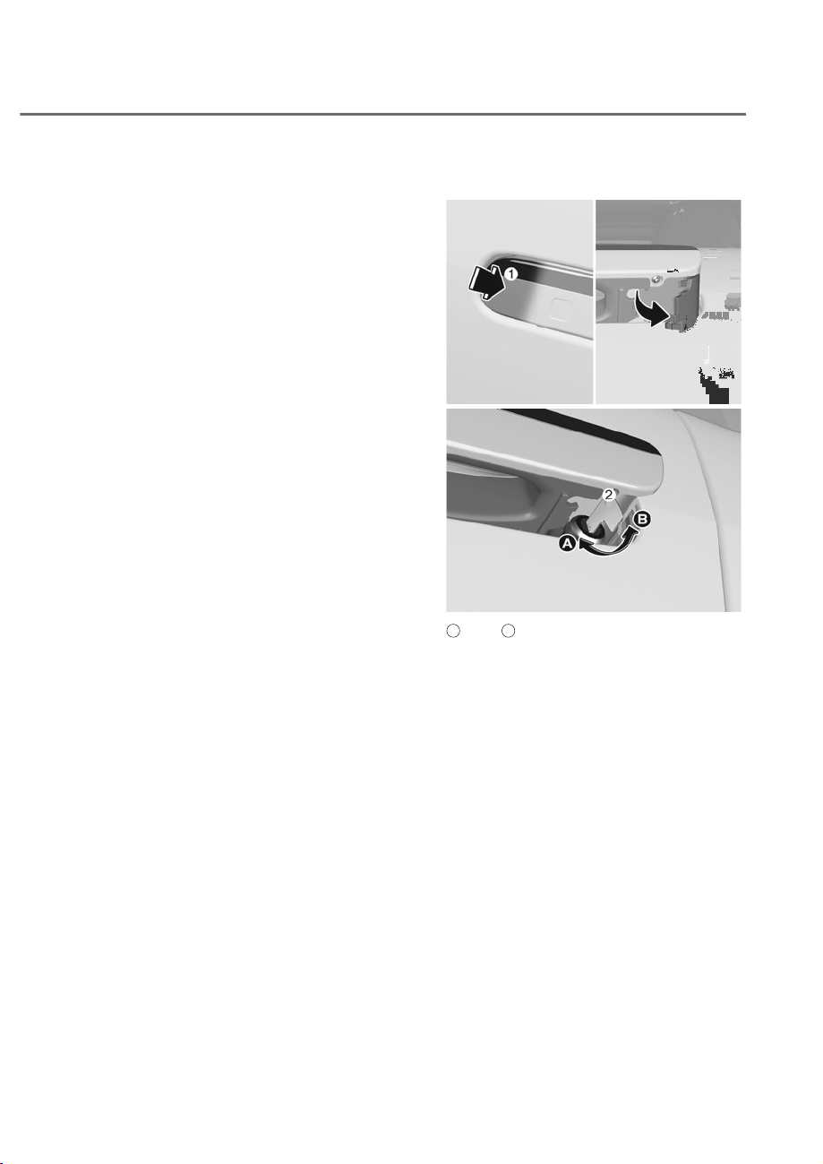
5-35
05
&DXWLRQVZKHQZDVKLQJWKHYHKLFOH
If touch sensors are equipped, an
unexpected warning may sound, and
the doors might lock or unlock when the
smart key is within the detectable range
and the outside door handle is wet.
• Conditions when using the automatic
car wash
- Prior to wash, keep the Engine
Start/Stop button in ACC or ON
position, stay in N (Neutral) and
enter the automatic car wash. For
details of staying in N (Neutral),
refer to “To Stay in N (Neutral)”
section in chapter 6.
- Enter the automatic car wash with
the doors locked and the outside
door handle in its original position.
• Conditions when self car washing
- Wash your car with the doors locked
and the outside door handle in its
original position.
- If any water or a rag is touching the
door handle lock/unlock sensor, the
door handle will pop out and the
door will be unlocked. To prevent
unintended operation of the door
handle sensor, keep the key over 6.5
ft. (2 m) away from the vehicle.
- Be careful to avoid theft of your
smart key during car wash.
- Make sure to keep your smart key
with you after car wash or keep
the key over 6.5 ft. (2 m) from the
vehicle.
- If an unexpected waring sounds
during car wash, keep the Engine
Start/Stop button in ACC or ON
position and leave the smart key
inside the vehicle.
Using mechanical key
ORS051019
ORS051019
ORS051260
ORS051260
A
: Lock,
B
: Unlock
Lock or unlock the door with the
mechanical key. Use the mechanical key
according to the following direction.
1. Pull the door handle while pressing
the front part of the outside door
handle M (front side of the vehicle).
Then remove the cover under the rear
part of the door handle.
2. Insert the key into the key hole N and
turn it to lock or unlock the door.
3. After unlocking with the mechanical
key, remove the key.
4. Release the door handle.
5. Press the front part of the door handle
again to manually pop out the handle,
then pull it out to open the door.
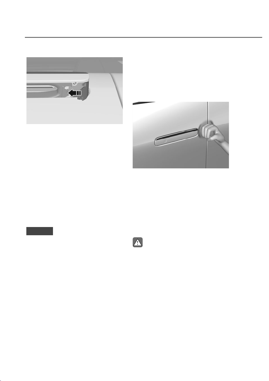
5-36
Convenience Features
ORS051286
ORS051286
6. Reinstall the removed cover.
When the door handle or keyhole
freezes, lightly tap or indirectly warm it
(for example, hand temperature, etc.) to
remove ice.
For more details, refer to “Removing
Ice from Door Handle” section in this
chapter.
Locking and unlocking the door multiple
times with the key or lock button or
switch may engage the protection circuit
and temporarily disable the lock/unlock
function. When you exit the vehicle,
engage the parking brake, turn the
engine off, close all windows and lock
the doors.
NOTICE
Do not apply excessive force on the
door and door handle. It may damage
the door and door handle.
Removing ice from door handle
Inner part of the door handle may freeze
during cold winter. Tap the door handle
with the palm side of the fist to remove
the ice.
Follow the instructions below to remove
the ice from the door handle.
ORS051246
ORS051246
1. Tap around the door handle with the
palm side of your fist to remove the
ice inside the door handle.
2. Unlock the door and see if the door
handle pops out. If the handle does
not pop out, continue tapping around
the handle and remove more ice.
3. Hold the door handle, and open and
close the door multiple times to
remove the remaining ice.
CAUTION
• Do not tap the vehicle while wearing
accessories or carrying other objects.
It may damage the painting.
• Do not tap the vehicle with tools
or with excessive force. Vehicle
body may be caved. Tap it with the
strength when knocking on the door.
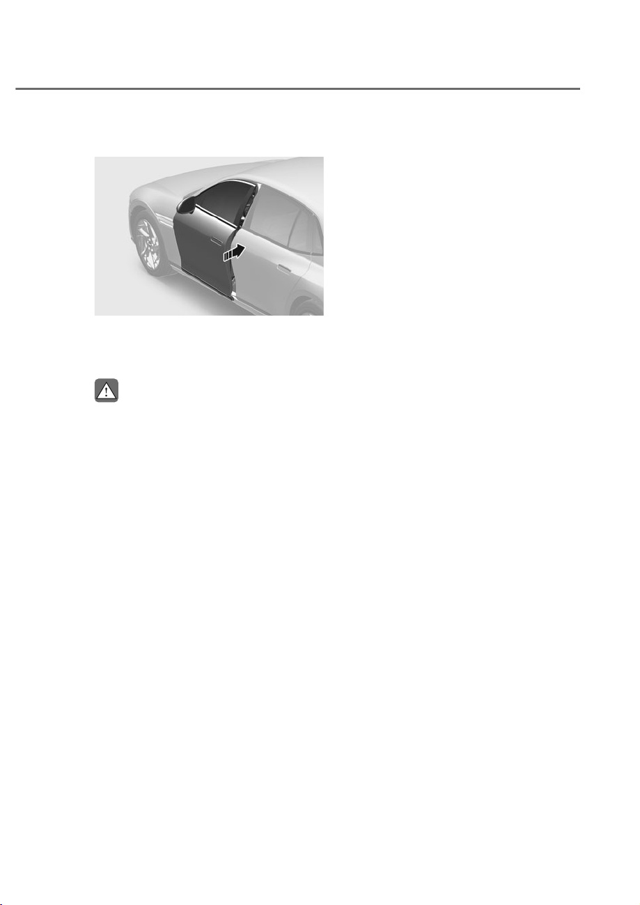
5-37
05
Power Door Latch (if equipped)
ORS051020L
ORS051020L
If a door does not close completely but
is closed to the first detent position, the
door will close automatically.
CAUTION
To reduce the risk of injury:
• Before closing the door, check there
are no obstructions in the path of the
door.
• Keep your fingers away from the
edge of the door or they may become
trapped when the power door latch
operates.
Resetting the power door latch
The power door latch may need to be
reset after the battery is discharged or
disconnected or a related fuse has been
replaced or disconnected.
To reset the power door latch, perform
the following steps:
1. Close the door to the first detent
positon.
2. Open the door.
When this is complete, the power door
latch resets.
If the door does not close completely
even after resetting the power door
latch, have the vehicle inspected by an
authorized retailer of Genesis Branded
products.
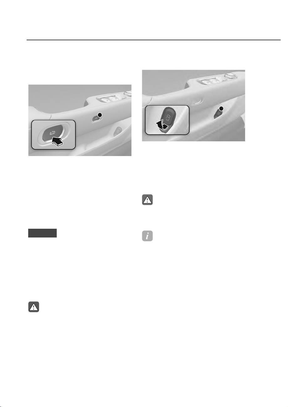
5-38
Convenience Features
Operating Door Locks from
Inside the Vehicle
Using the door open button
ORS051021
ORS051021
Press the door open button from inside
the vehicle to open the door.
• Always close and lock the doors when
the vehicle is moving. Locking the
doors prevent others from entering
the vehicle while the vehicle is
stopped or moving slowly.
• If any door is opened, the doors will
not lock even though the central door
lock switch is pressed.
NOTICE
• Do not open the door excessively
multiple times using the door open
button. It may engage the protection
circuit and temporarily disable the
button.
• If equipped with the Easy Close
feature, the door will open about 7.9
in. (20 cm). Check for any obstacles
before opening the door.
WARNING
Only open the door with the door open
button when the vehicle has completely
stopped.
The door may open while the vehicle is
in motion if you press the button.
Opening the door manually
ORS051026
ORS051026
If the door does not open with the door
open button due to battery discharge or
vehicle breakdown, pull the emergency
open lever under the door pocket twice
to open the door. You may use the
emergency open lever even if there is no
problem with the door open button.
CAUTION
Do not apply excessive force on the
door, door handle and emergency open
lever to avoid damage.
Information
The door will open in the following
conditions by pulling the emergency open
lever only once.
• When the door emergency open lever is
already used once (for all doors)
• When the battery is low. (for driver
side door)
• When the mechanical key on the
driver’s door is used
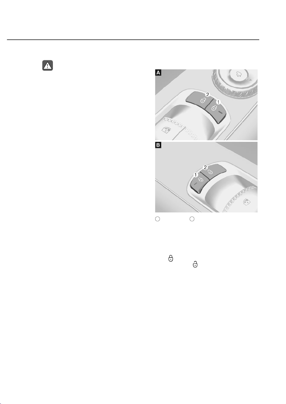
5-39
05
WARNING
• Be careful when opening doors and
watch for vehicles, motorcycles,
bicycles or pedestrians approaching
the vehicle in the path of the door.
Opening a door when something is
approaching may cause damage or
injury.
• The doors should always be fully
closed and locked while the
vehicle is in motion. If the doors
are unlocked, the risk of being
thrown from the vehicle in a crash is
increased.
• Do not leave the elderly, children
or animals unattended in your
vehicle. An enclosed vehicle can
become extremely hot, causing
death or serious injury to the elderly,
unattended children or animals who
cannot escape from the vehicle.
Children might operate features of
the vehicle that could injure them,
or they could encounter other harm,
possibly from someone gaining entry
to the vehicle.
• Do not pull the emergency open
lever while the vehicle is in motion.
If a door opens while driving, it may
lead to a serious injury or death.
Using the door lock/unlock switch
ORS051027
ORS051027
ORS051028
ORS051028
A
: Driver’s door,
B
: Front passenger’s door
Driver and passenger door central door
lock switch
The driver and passenger side door
armrest is equipped with a central door
lock switch. The lock switch is indicated
by a (
) symbol. The unlock switch is
indicated by a (
) symbol.
When the lock switch M is pressed, all
the vehicle doors will lock.
When the unlock switch N is pressed, all
the vehicle doors will unlock.
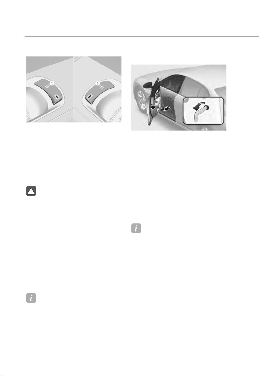
5-40
Convenience Features
ORS051029
ORS051029
Rear door lock switch
Press the lock switch M on the rear door
to lock the corresponding door. When
the door is locked, the indicator light on
the switch illuminates.
However, if the door is opened, the door
will not lock.
Note that the doors cannot be unlocked
with the rear door lock switch.
WARNING
• Lock all the doors using the central
door lock switch in the driver's seat
or front passenger's seat before
driving. Especially when children
are in the vehicle. If the vehicle door
accidentally opens while the vehicle
is in motion, it may lead to a serious
injury.
• Do not leave the Smart Key in your
vehicle with unsupervised children.
Unattended children could press the
Engine Start/ Stop button and may
operate power windows, lock the
doors or other controls, or even make
the vehicle move, which could result
in serious injury or death.
Information
If the door is locked with children or
animals in your vehicle, you can unlock
the driver's door the mechanical key. For
more details, refer to "Using Mechanical
Key" section in this chapter.
In case of an emergency
ORS051030L
ORS051030L
In case of emergency such as when the
battery is discharged, the only way to
lock the door(s) is with the mechanical
key from the outside key hole.
Doors without an outside key hole can be
locked as follows:
1. Open the door. Then, remove the plug
to use emergency lock.
2. Insert the key into the emergency
door lock hole and turn the key
to the lock position (left door:
counterclockwise, right door:
clockwise).
3. Close the door securely.
Information
If the electrical power door lock switch
does not operate (for example, dead car
battery) and the trunk is closed, you will
not be able to open the trunk until power
is restored.
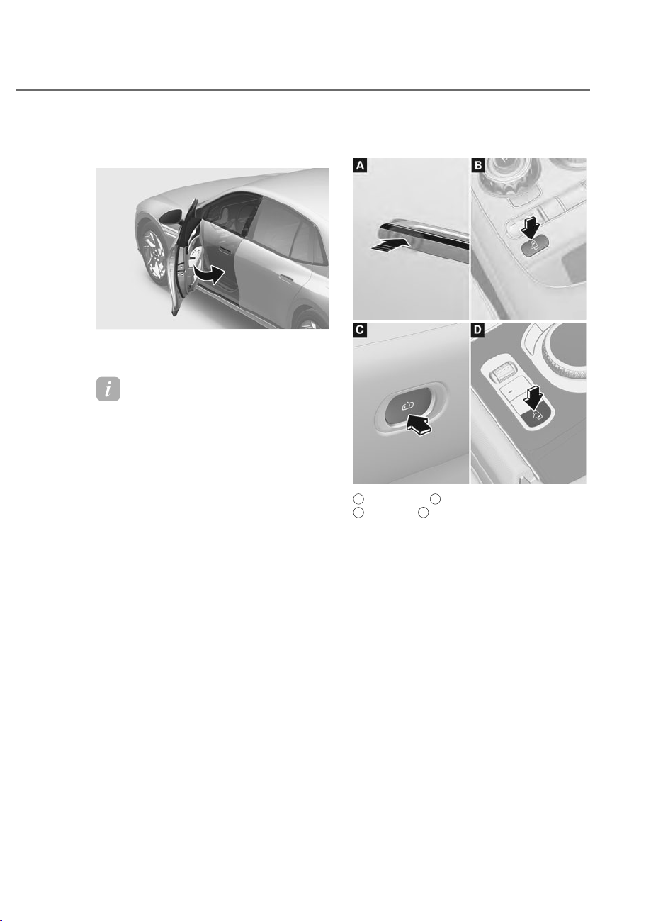
5-41
05
Easy Door Close (if equipped)
ORS051258L
ORS051258L
Each door closes automatically with a
door switch.
Information
If the vehicle is equipped with the easy
door close feature, pressing the door
open button while the door is closed will
automatically open the door about 7.9 in.
(20 cm)
Closing door with switch
ORS051266
ORS051266
ORS051267
ORS051267
A
: Door handle,
B
: Front center console,
C
: Door trim,
D
: Rear armrest console
Touch the lock/unlock sensor (engraved
part) of the door handle from the
outside, or press the open switch from
the inside, or press the close switch on
the console.
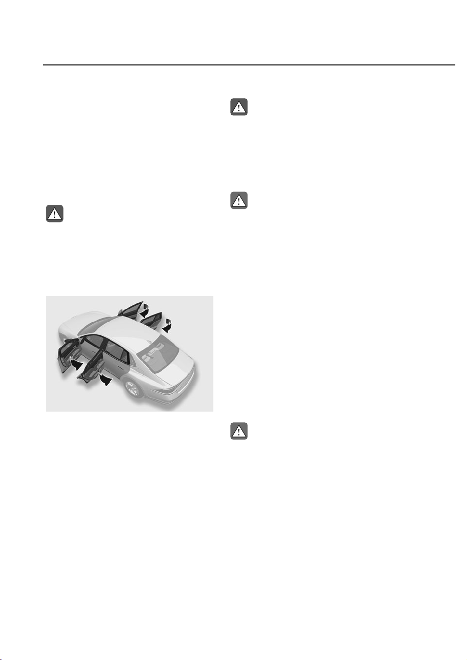
5-42
Convenience Features
Closing driver’s door by depressing
brake (if equipped)
If you set the 'Link to Brake Pedal’, you
can close the driver’s door by depressing
the brake pedal.
To set the brake pedal link, go to ‘Setup
Ɍ9HKLFOHɌ$XWRPDWLF'RRU2SHUDWLRQɌ
Link to Brake Pedal’ in the infotainment
system.
WARNING
Completely enter the vehicle before
depressing the brake pedal to close the
door. Leaving a leg out of the vehicle
and closing the door may trap your leg
and lead to injury.
Closing the door remotely
ORS051025L
ORS051025L
To close the door remotely, point the
smart key towards the vehicle and press
and hold the door lock button on the
smart key for over 3 seconds while the
engine is turned off. If the distance from
the vehicle and your smart key changes
while the door is being closed, the door
may not be completely closed. Do not
stand too far away from the door when
remotely closing the door.
WARNING
• Be careful not to get a body part
caught between the door and vehicle
when the door is being closed.
• Make sure there are no people or
other objects between the door and
the vehicle before closing the door.
CAUTION
Check if the hazard warning light has
blinked once after all doors are closed.
If it blinks once, the vehicle is armed.
(see "Theft Alarm System" for armed
state.) It does not blink if there are
doors that are not completely closed.
Check for unclosed doors.
Resetting easy door close
To reset the easy door close feature,
close the door to the second detent
position and open the door again.
Reset the easy door close feature in the
following conditions.
- The discharged battery is recharged
- The disconnected battery is
reconnected
- Related fuses are disconnected and
reinstalled
CAUTION
If the easy door close feature does
not work properly after reset, have
you contact an authorized retailer of
Genesis Branded products

5-43
05
Information
• The following situations are normal
and may happen when using the easy
door close feature.
- Before resetting easy door close,
opening and closing the door
manually may require more strength.
- When the door opens about 7.9 in.
(20 cm) and stops, or is automatically
opened or closed, a sound may occur
due to motor rotation.
- If the door is repeatedly opened and
closed manually, a noise may sound
due to the motor brake.
- When the battery is low, starting the
engine while the door is open may
cancel the initial setting of the easy
door close feature. When canceled,
manually opening and closing the
door requires more force. Pressing
the door close button or closing the
door manually will normalize the
setting of the easy door close feature.
• During cold weather, opening and
closing the door manually may require
more strength due to low lubrication.
If the door can be automatically closed
with the door switch or key, the doors
are working properly.
WARNING
If you stay in the vehicle for a long time
while the weather is very hot or cold,
there are risks of injuries or danger to
life. Do not lock the vehicle from the
outside when someone is in the vehicle.
Automatic Door Lock and Unlock
)HDWXUHV
Your vehicle is equipped with features
that will automatically lock or unlock
your vehicle based on settings you select
in the infotainment system screen.
Auto LOCK Enable on driving
When this feature is set in the
infotainment system screen, all the doors
will be locked automatically when the
vehicle exceeds 9 mph (15 km/h).
Auto LOCK Enable on shift
When this feature is set in the
infotainment system screen, all the doors
will be locked automatically when the
vehicle is shifted out of P (Park) while the
engine is running.
Auto UNLOCK On shift to P
When this feature is set in the
infotainment system screen, all the doors
will be unlocked automatically when the
vehicle is shifted back into P (Park) while
the engine is running.
Auto UNLOCK Upon vehicle Off
When this feature is set in the
infotainment system screen, all the doors
will be unlocked automatically when the
vehicle is turned off.
See additional information in supplied
Infotainment Manual.
Additional unlock safety feature air
bag deployment
As an additional safety feature, all doors
will be automatically unlocked when an
impact causes the air bags to deploy.
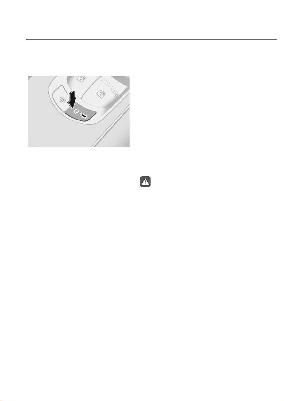
5-44
Convenience Features
Electronic Child Safety Lock (if
equipped)
ORS051031
ORS051031
When the electronic child safety lock
button is pressed and the indicator
light on the button illuminates, the rear
doors cannot be opened from inside the
vehicle.
• The rear door window cannot be
opened or closed while the electronic
child safety lock button is in the LOCK
position (indicator light ON).
For more details, refer to “Windows”
section in this chapter.
• Electronic child safety lock does not
automatically turn on unless the driver
presses the electronic child safety
lock button.
• If 3 minutes passes after the Engine
Start/Stop button is pressed to the
OFF position, the indicator on the
button turns off, and the driver cannot
turn off electronic child safety lock by
pressing the button. To turn off the
function, press the Engine Start/Stop
button to the ACC or ON position, and
then press the electronic child safety
lock button.
• If the power is supplied again after
removing the battery or battery is
discharged while the electronic child
safety lock button is in the LOCK
position, press the button once more
to match the state of the indicator on
the electronic child safety lock button
and actual status of the electronic
child safety lock function.
• If the airbag is activated while the
electronic child safety lock button
is in the LOCK position (indicator
light ON), the rear doors will unlock
automatically.
• Vehicles equipped with the electronic
child safety lock feature is not
provided with a manual child safety
lock.
WARNING
If children accidentally opens the rear
door while the vehicle is in motion, they
could fall out of the vehicle. Electronic
child safety lock should always be used
whenever children are in the vehicle.

5-45
05
NOTICE
Child safety lock failure
OJX1059018L
OJX1059018L
When electronic child safety lock does
not work even though the button is
pressed, the message will be displayed
and an alarm will sound. If this occurs,
have the vehicle inspected by an
authorized retailer Genesis Branded
products.
Safe Exit Assist (if equipped with
electronic child safety lock)
Safe Exit Assist prevents the rear
occupant from opening the rear door.
When an approaching vehicle from the
rear area is detected after the vehicle
stops, the rear doors will not unlock even
when the driver tries to unlock the rear
doors using the electronic child safety
lock button.
For more details, refer to “Safe Exit Assist
(SEA)” section in chapter 7.

5-46
Convenience Features
7+()7ʏ$/$506<67(0
This system helps to protect your vehicle
and valuables. The horn will sound and
the hazard warning lights will blink
continuously if any of the following
occur:
- A door is opened without using the
smart key.
- The trunk is opened without using the
smart key.
- The engine hood is opened.
The alarm continues for 30 seconds, then
the system resets. To turn off the alarm,
unlock the doors with the smart key.
The Theft Alarm System automatically
sets 30 seconds after you lock the doors
and the trunk. For the system to activate,
you must lock the doors and the trunk
from outside the vehicle with the smart
key or by touching the touch sensor on
the outside of the door handle with the
smart key in your possession.
The hazard warning lights will blink and
the chime will sound once to indicate the
system is armed.
Once the security system is set, opening
any door, the trunk, or the hood without
using the smart key will cause the alarm
to activate.
The Theft Alarm System will not set if the
hood, the trunk, or any door is not fully
closed. If the system will not set, check
the hood, the trunk, or the doors are fully
closed.
Do not attempt to alter this system or
add other devices to it.
Information
• Do not lock the doors until all
passengers have left the vehicle. If the
remaining passenger leaves the vehicle
when the system is armed, the alarm
will be activated.
• If the vehicle is not disarmed with the
smart key, open the doors by using the
mechanical key and start the engine by
directly pressing the Engine Start/Stop
button with the smart key.
• If the system is disarmed by unlocking
the vehicle, but neither a door or the
trunk is opened within 30 seconds, the
doors will relock and the system will
rearm automatically.

5-47
05
$'9$1&('5($52&&83$17$/(57ʚ52$ʛʚ,)(48,33('ʛ
Advanced Rear Occupant Alert is
provided to help prevent the driver
from leaving the vehicle with the rear
passenger left in the vehicle.
System Setting
To use Rear Occupant Alert, it must be
enabled from the Settings menu in the
infotainment system screen. Select:
- 6HWXSɌ9HKLFOHɌ&RQYHQLHQFHɌ5HDU
Occupant Alert
See additional information in supplied
Infotainment Manual.
Information
'HVHOHFWµ5HDU2FFXSDQW$OHUW¶IURPWKH
settings menu to turn the system off.
System Operation
• First alert
When you turn off the engine and
open the driver’s door after opening
and closing the rear door, the ‘Check
rear seats’ warning message appears
on the instrument cluster.
• Second alert
After the first alert, the second alert
operates when any movement is
detected in the vehicle after the
driver’s door is closed and all the
doors are locked. The horn will sound
for approximately 25 seconds. If
the system continues to detect a
movement, the alert operates up to
8 times. Also, a text message is sent
to members of Genesis Connected
Services (if available). If the system
continues to detect a movement, the
alert operates up to 8 times.
Unlock the doors with the smart key
to stop the alert.
• The system detects movement in the
vehicle for 10 minutes after the door
is locked.
Information
• The second alert is available for
YHKLFOHVHTXLSSHGZLWKWKH52$VHQVRU
• 5HDU2FFXSDQW$OHUWDOVRDFWLYDWHV
when movement is detected in the cargo
area.
• The second alert is activated only after
the prior activation of the first alert.
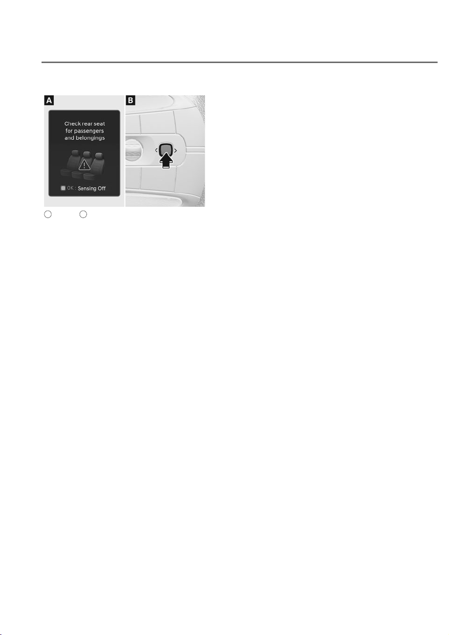
5-48
Convenience Features
ORS031142L
ORS031142L
A
: Cluster,
B
: Steering wheel
If you do not want to use Rear Occupant
Alert, press the OK button on the steering
wheel when the first alert is displayed on
the cluster. Doing so will deactivate the
second alert one time.
• If the vehicle is started remotely (if
equipped with Remote Start), inside
movement detection will stop.
System Precautions
• Make sure that all the windows are
closed. If the window is open, the
alert may operate by the sensor
detecting an unintended movement
(for example, wind or bugs).
• The alert may operate if movement
in the driver or passenger seat is
detected.
• If the doors are locked with a
passenger inside the vehicle, the alert
may operate.
• An alert can occur if there is an impact
on the vehicle.
• If boxes or objects are stacked in the
vehicle, the system may not detect
passengers. Or, the alert may operate
if the boxes or objects fall off.
• The alert may operate when the
vehicle is pushed or shaken, or while
washed, or by surrounding noise or
vibration after the vehicle is locked.
• The alert may operate when there
are metallic or liquid objects in the
vehicle.
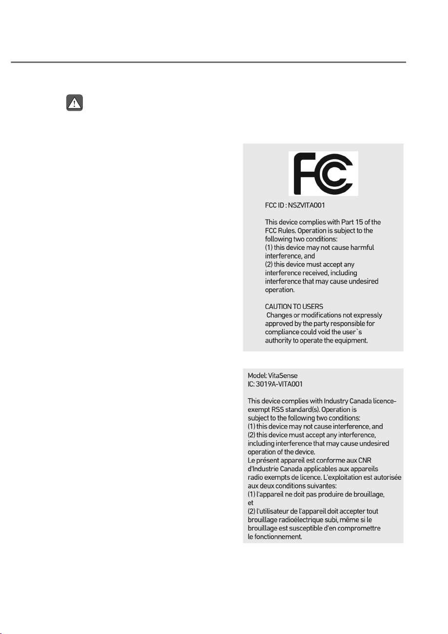
5-49
05
WARNING
Even if your vehicle is equipped with
Rear Occupant Alert, always make sure
to check the rear seat before you leave
the vehicle.
Advanced Rear Occupant Alert may not
operate when:
• Movement does not continue for
a certain period of time or the
movement is small.
• A child is not seated in a child
restraint system.
• The detection signal is weak because
the signal is obscured by seat or CRS
(for example, child is restrained in
the forward-facing CRS).
• Movement is detected in areas other
than the rear seats.
• The rear passenger is covered with a
fabric containing metallic substance
such as a blanket.
• An object in the vehicle blocks the
sensor.
• The sensor is contaminated by
foreign material.
• An animal at the rear seat is not large
enough to be detected by the sensor
or there is hardly any movement.
• Attaching objects or modifying the
interior ceiling, or the interior ceiling
is deformed or damaged.
• There are electronic interference
around the vehicle.
• Other environmental reasons that
may affect the system.
Declaration of Conformity
The radio frequency components (ROA
Radar Sensor) complies:
- For USA
OANATEL323
OANATEL323
- For Canada
OANATEL324
OANATEL324
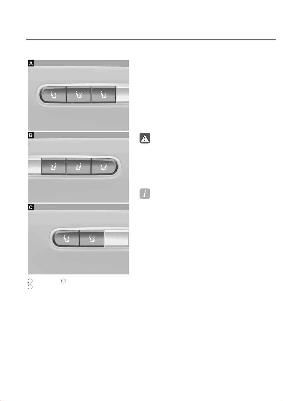
5-50
Convenience Features
INTEGRATED MEMORY SYSTEM
ORS051033
ORS051033
ORS051034
ORS051034
ORS051035
ORS051035
A
: Driver’s seat,
B
: Front passenger’s seat,
C
: Rear seat (if equipped)
Integrated Memory System for the
driver’s seat is provided to store and
recall the following memory settings with
a simple button operation.
• Seat position
• Steering wheel position (power
adjustment)
• Side view mirror position
• Head-Up Display (HUD) position and
brightness (if equipped)
WARNING
Never attempt to operate the
integrated memory system while the
vehicle is moving.
This could result in loss of control, and
an accident causing death, serious
injury, or property damage.
Information
• If the battery is disconnected, the
memory settings will be erased.
• If integrated memory system does not
operate normally, have the system
inspected by an authorized retailer of
Genesis Branded products.

5-51
05
Storing Memory Positions
1. Shift to P (Park) while the Engine
Start/Stop button is in the ON
position.
2. Adjust the seat position, side view
mirror position, steering wheel
position and head-up display height/
brightness to the desired position.
3. Press and hold one of the memory
buttons (1, 2 or 3). The system will
beep twice when the memory has
been successfully stored.
‘Settings 1 (2 or 3) saved’ will appear
on the cluster LCD display.
Recalling Memory Positions
1. Shift to P (Park) while the Engine
Start/Stop button is in the ON
position.
2. Press the desired memory button (1,
2 or 3). The system will beep once,
and then the seat position, side
view mirror position, steering wheel
position and head-up display height/
brightness will automatically adjust to
the stored positions.
‘Settings 1 (2 or 3) applied’ will appear
on the cluster LCD display.
If you press the corresponding button
which the setting is being recalled, the
setting will temporarily deactivate. If you
press the other buttons, the setting of
the pressed button will activate.
For example, if you press number 1
button with the number 1 setting in
operation, the setting will temporarily
deactivate. If you press the number
2 button, the number 2 setting will
activate.
If you adjust the seat, side view mirror,
steering wheel or head-up display while
recalling the stored positions, the pre-set
settings will become ineffective.
Information
• Up to 3 memories for front seats and
up to 2 memories for rear seats can be
saved.
• 2QO\WKHGULYHU¶VVHDWPHPRU\LV
displayed by message through the
infotainment system screen.
• The front and rear passenger seat
position memory can be saved and
DGMXVWHGZKLOHWKHYHKLFOHLVEHLQJ
driven.
• If the seat is moved to the foremost
position, or if the seatback is completely
tilted forward, the seat memory cannot
be saved.
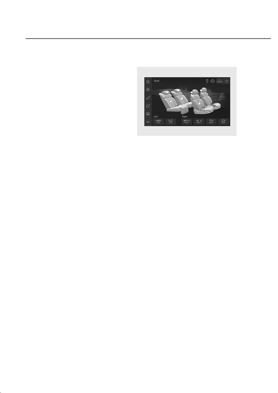
5-52
Convenience Features
Seat Easy Access
Seat easy access will move the driver’s
seat and steering wheel automatically as
follows:
Easy accessing for driver's seat
• Exiting the vehicle:
The driver’s seat, steering wheel and
seat bolster will move as follows when
the Engine Start/Stop button is in the
OFF position with the gear in P (Park)
and the driver’s door open.
- Driver seat: Moves rearward
depending on the distance selected
from the Settings menu in the
infotainment system.
- Steering wheel: Moves upward
- Seat bolster (if equipped): Adjusted
to the default position.
However, the driver’s seat may not
move rearward if there is not enough
space between the driver’s seat and
the rear seats.
Also, on a regular basis, the steering
wheel will also move forward to adjust
its location by itself.
• Entering the vehicle:
The driver's seat, steering wheel, and
seat bolster will move as follows from
the position set by the driver when the
driver's door is closed after exiting the
vehicle.
- Driver seat: Moves back to its
original position.
- Steering wheel: Moves back to its
original position.
- Seat bolster (if equipped): Adjusted
to the default position.
• Easy accessing for rear seat
ORS031024L
ORS031024L
The rear seat automatically moves when
exiting the vehicle. Adjust the setting
of each rear seat from the rear armrest
touchscreen.
• Setting Seat Easy Access :
You can set the Seat Easy Access
function from the Settings menu
in the infotainment system screen.
Select:
- Driver seat
6HWXSɌ9HKLFOHɌ6HDWɌ6HDWLQJ
(DV\$FFHVVɌ'ULYHU6HDW(DV\
$FFHVVɌ1RUPDO'LVWDQFH
Extended Distance/Off
- Steering wheel
6HWXSɌ9HKLFOHɌ6HDWɌ6HDWLQJ
(DV\$FFHVVɌ6WHHULQJ(DV\$FFHVV
- Left rear seat
6HWXSɌ9HKLFOHɌ6HDWɌ6HDWLQJ
(DV\$FFHVVɌ/HIW5HDU6HDW
- Right rear seat
6HWXSɌ9HKLFOHɌ6HDWɌ6HDWLQJ
(DV\$FFHVVɌ5LJKW5HDU6HDW
See additional information in supplied
Infotainment Manual.

5-53
05
Resetting the System
Take the following procedures to reset
integrated memory system, when one of
the seat does not operate properly.
Resetting integrated memory
system
1. Place the Engine Start/Stop button in
the ON position and the shift the gear
to P (Park). Open the corresponding
door of the seat that does not work
properly.
2. Adjust the corresponding seat and
seatback to the foremost position.
3. Press the number 1 button and push
forward the seat movement switch
over 2 seconds simultaneously.
While resetting integrated memory
system
1. Resetting starts with a notification
sound.
2. The corresponding seat and seatback
is adjusted to the rearward position
with the notification sound.
3. The corresponding seat and seatback
is re-adjusted to the default position
(central position) with the notification
sound.
However, in the following cases, the
resetting procedure and the notification
sound may stop.
• The memory button is pressed.
• The seat control switch is operated.
• The gear is shifted out of P (Park).
• The driving speed exceeds
2 mph (3 km/h).
• The driver’s door is closed.
NOTICE
• While integrated memory system
is being reset, if the resetting
and notification sound stops
incompletely, restart the resetting
procedure again.
• Make sure that there is no objects
around the driver’s seat in advance
of resetting the integrated memory
system.

5-54
Convenience Features
The Smart Posture Care system
automatically provides a healthy posture
(position) for the driver’s back, and sets
the steering wheel, side view mirrors,
head-up display positions according to
the driver’s body measurements.
Information
,IWKH6HDW3RVWXUH&DUHV\VWHPGRHVQRW
operate normally, have the system checked
by an authorized retailer of Genesis
Branded products.
OJWEV051211N
OJWEV051211N
1. Check that the gear is in P (Park) while
the Engine Start/Stop button is in the
ON position.
2. 6HOHFWȁ6HWXSɌ9HKLFOH6HWWLQJVɌ6HDW
Ɍ6PDUW3RVWXUH&DUHɌ(QWHU'ULYHUȂV
Information’ from the Settings menu
in the infotainment system screen.
3. Enter information (Height, inseam,
Weight) in the infotainment system
screen.
4. After entering the driver’s information,
SUHVVȁ3RVWXUH$QDO\VLVɌ$GMXVW
Posture’. The driver’s seat, steering
wheel, side view mirror and head-up
display will be adjusted.
See additional information in supplied
Infotainment Manual.
60$57326785(&$5(6<67(0ʚ,)(48,33('ʛ

5-55
05
Motor Driven Power Steering
(MDPS)
The system assists you with steering the
vehicle. If the vehicle is turned off or
if the power steering system becomes
inoperative, you may still steer the
vehicle, but it will require increased
steering effort.
Should you notice any change in the
effort required to steer during normal
vehicle operation, have the system
checked by an authorized retailer of
Genesis Branded products.
CAUTION
If Motor Driven Power Steering does not
operate normally, the
warning light
and the message ‘Check motor driven
power steering’ will illuminate on the
instrument cluster. You may steer the
vehicle, but it will require increased
steering efforts. Take the vehicle to an
authorized retailer of Genesis Branded
products and have the system checked
as soon as possible.
Information
The following symptoms may occur during
normal vehicle operation:
• The steering effort may be high
immediately after pressing the Engine
6WDUW6WRSEXWWRQWRWKH21SRVLWLRQ
This happens as the system performs
the MDPS system diagnostics. When
the diagnostics are completed, the
steering wheel effort will return to its
normal condition.
• When the battery voltage is low, you
might have to put more steering effort.
However, it is a temporary condition so
that it will return to normal condition
after charging the battery.
• A click noise may be heard from the
MDPS relay after the Engine Start/Stop
EXWWRQLVLQWKH21RU2))SRVLWLRQ
• Motor noise may be heard when the
vehicle is at a stop or at a low driving
speed.
• When you operate the steering wheel
in low temperatures, abnormal noise
may occur. If the temperature rises, the
noise will disappear. This is a normal
condition.
• When an error is detected from MDPS,
the steering effort assist function will
not be activated in order to prevent
fatal accidents. Instrument cluster
warning lights may be on or the
steering effort may be high. If these
symptoms occur, drive the vehicle to
a safe area as soon as it is safe to do
so. Have the system checked by an
authorized retailer of Genesis Branded
products as soon as possible.
STEERING WHEEL
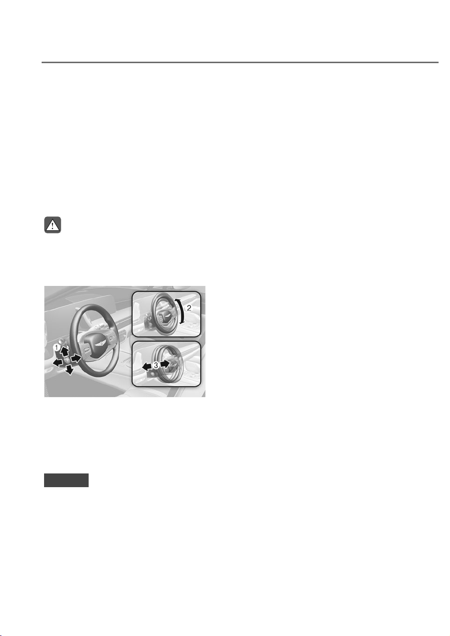
5-56
Convenience Features
Tilt/Telescopic Steering
When adjusting the steering wheel to a
comfortable position, adjust the steering
wheel so that it points toward your chest,
not toward your face. Make sure you can
see the instrument cluster warning lights
and gauges. After adjusting, push the
steering wheel both up and down to be
certain it is locked in position.
Always adjust the position of the steering
wheel before driving.
WARNING
NEVER adjust the steering wheel while
driving. This may cause loss of vehicle
control resulting in an accident.
Power adjustment
ORS051036
ORS051036
To change the steering wheel angle and
height:
• Push the switch M up and down to
adjust the angle N.
• Push the switch M forward or
rearward to adjust the height O.
NOTICE
Do not adjust the steering wheel
longer than necessary when the
engine is turned off. This may result in
unnecessary battery drain.
Resetting steering wheel power
adjustment
If adjustment is no longer possible within
the operable range while adjusting the
steering wheel position (angle or height),
reset as follows.
1. From the position the steering wheel
has stopped, push the control switch
M for 10 seconds in the direction you
were adjusting the steering wheel.
The steering wheel will move in the
direction the control switch is pushed.
2. Continue pushing the switch M for
at least 2 seconds after the steering
wheel has stopped. Resetting will be
complete after the operational range
is recognized.
If the adjustment is still not possible
after resetting the steering wheel
power adjustment, have the system
inspected by authorized retailer of
Genesis Branded products.
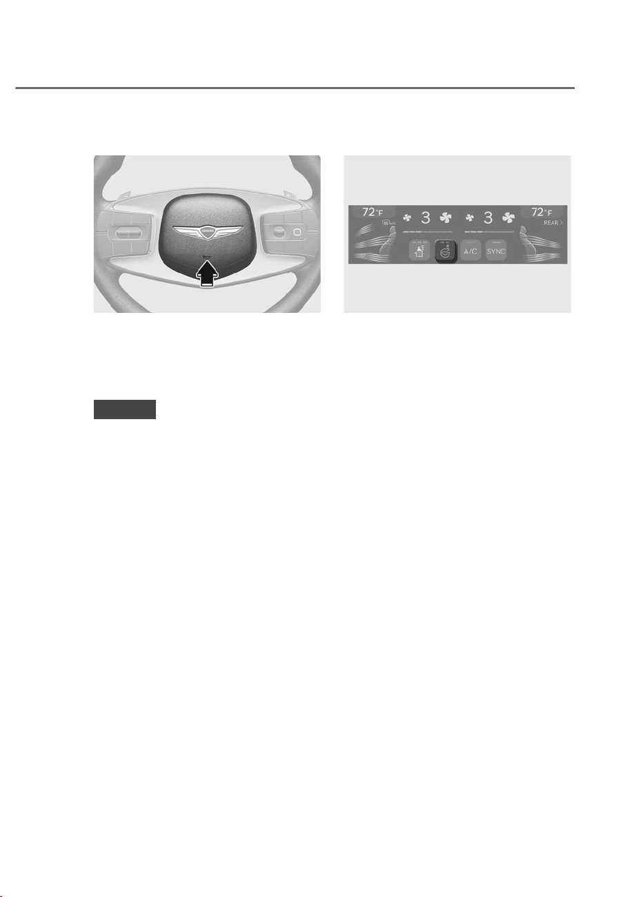
5-57
05
Horn
ORS051038
ORS051038
To sound the horn, press the area
indicated by the horn symbol on your
steering wheel (see illustration). The
horn will operate only when this area is
pressed.
NOTICE
Do not strike the horn severely to
operate it, or hit it with your fist. Do not
press on the horn with a sharp-pointed
object.
Heated Steering Wheel
ORS052037N
ORS052037N
While the engine is running, touch the
heated steering wheel icon to warm the
steering wheel.
Manually adjusting temperature
Each time you press the heated steering
icon, the temperature changes as
follows.
• 2))Ɍ+,*+Ɍ/2:
• Pressing the icon when temperature
is low, the heated steering wheel will
turn off.
Automatically adjusting
temperature
• When HIGH is manually selected, the
heated steering wheel automatically
changes to the LOW position after 30
minutes. You can turn off the heated
steering wheel by pressing the icon to
the OFF position.
• When LOW is manually selected, the
heated steering wheel will not be
controlled manually.

5-58
Convenience Features
Automatic Controls Linked to
Climate Control Settings
The heated steering wheel automatically
controls the steering wheel temperature
depending on the ambient temperature
when the engine is running.
To use this feature, it must be enabled
from the Settings menu in the
infotainment system screen.
Select:
6HWXSɌ9HKLFOHɌ6HDWɌ:DUPHU
9HQWLODWLRQ)HDWXUHVɌ$XWRPDWLF
Controls Linked to Climate Control
6HWWLQJVɌ6WHHULQJ:KHHO:DUPHU
See additional information in supplied
Infotainment Manual.
• If you press the heated steering wheel
icon when the feature is set, you must
control the heated steering wheel
manually.
• The heated steering wheel defaults
to the OFF position whenever the
Engine Start/Stop button is pressed
to the ON position. However, if the
Automatic Controls Linked to Climate
Control Settings feature is ON, the
heated steering wheel will turn on
and off depending on the outside
temperature.
NOTICE
• Do not install any cover or accessory
on the steering wheel. The cover or
accessory could cause damage to
the heated steering wheel system.
• Do not strike the steering wheel grip
surface with sharp objects. It may
damage the heating element in the
steering wheel.
• Do not clean the steering wheel
surface using the following products.
Heater and steering wheel surfaces
may be damaged.
- Organic solvents such as thinner,
alcohol and gasoline
- Chemical products such as leather
cleaner, coating agent, and wax

5-59
05
Steering Wheel Grip Sensor
While driving the vehicle with the Driver
Assistance system on, it detects whether
the driver is holding the steering wheel
and displays the Hands-off warning
when the driver is not holding the
steering wheel. See ‘Hands off warning’
from ‘Lane keeping assist (LKA)’, ‘Lane
following assist (LFA)’, ‘Highway driving
assist (HDA)’ section in chapter 7 for
details.
In the following situations, the sensor
may fail to detect the driver’s hands
although the driver is holding the
steering wheel.
• When the driver is wearing gloves.
• When accessories such as a cover is
attached on the steering wheel.
• When electronic device is touching
the steering wheel.
• When the steering wheel is wet.
CAUTION
The steering wheel sensor may not work
properly if the following precautions
are not followed.
• Do not modify the steering wheel
cover.
• Do not attach accessories on the rim
of the steering wheel.
• Do not touch the steering wheel with
electronic devices. (for example,
Laptop, tablet PC, etc)
• Do not touch the steering wheel with
metallic or conductive objects. (for
example, Tumbler, soda can, etc)
• Do not excessively wet the steering
wheel. (for example, spilled water,
wet tissue, vapor from steam wash)
Haptic Warning/Steering Wheel
Vibration Warning (if equipped)
If haptic steering wheel is equipped,
the Driver Assistance system vibrates
the steering wheel to warn the driver
when the system indicates hazardous
situations.
Setting haptic warning
• While the engine is on, select
6HWXSɌ9HKLFOHɌ'ULYHU$VVLVWDQFHɌ
Haptic Warning' on the infotainment
system.
• Vibration intensity can be set to
'Strong', 'Medium', 'Light' or 'Off'
See description of each function from
‘Driver Assistant System’ in chapter 7 for
details.
Rear Wheel Steering (RWS) (if
equipped)
The Rear Wheel Steering system helps
increase vehicle maneuverability and
improve vehicle stability by using an
electric motor to control the steering
angle of the rear wheels according to
the driving speed of the vehicle and the
steering angle of the front wheels.
When driving at low speed, turning
radius is reduced by steering the rear
wheels in the opposite direction of the
front wheels to increase maneuverability.
At high speeds, the rear wheels are
steered in the same direction as the front
wheels to improve stability when turning
and changing direction.

5-60
Convenience Features
NOTICE
When using snow chains, be sure to
turn off the Rear Wheel Steering by
selecting ‘Snow Chains Installed’ from
the Settings menu in the infotainment
system to protect the vehicle.
After removing the snow chain,
deselect ‘Snow Chains Installed’ from
the Settings menu in the infotainment
system. If it is not deselected, Rear
:KHHO6WHHULQJZLOOQRWRSHUDWH)RU
more details on setting the menu, refer
to “Winter Tire” section in Chapter 6.
CAUTION
• If there is a problem with the Rear
Wheel Steering system, a warning
light and warning message appears
on the instrument cluster and
Rear Wheel Steering system stops
working. If the warning light and
warning message are still displayed
even when the vehicle is stopped
and the engine is restarted, have the
vehicle checked by an authorized
retailer of Genesis Branded products.
• If the Rear Wheel Steering system
operation is stopped while the rear
wheels are not straight, the vehicle
may lean to one side while driving.
Information
With no warning light on the instrument
cluster, the following conditions are
normal:
• Immediately after starting the engine,
Rear Wheel Steering system performs
diagnostics and operates normally after
about 2 seconds.
• When turning the engine on or off,
Rear Wheel Steering system can
operate for about 2 seconds even
though the steering wheel is not steered
to check system condition.
• Motor noise may be heard when you
steer the vehicle while stopping or
driving at low speed.
• In driving conditions in which the rear
wheels are steered in the same direction
as the front wheels when (
) is on
the instrument cluster by pressing the
Lane Following Assist button on the
steering wheel or Highway Driving
Assist function is activated, keep the
rear wheels straight to improve Lane
Keeping Assist performance.
• ,Iµ6QRZ&KDLQV,QVWDOOHG¶LVVHOHFWHG
from the Settings menu in the
infotainment system, the Rear Wheel
Steering system stops operating, and
the rear wheels are straightened.
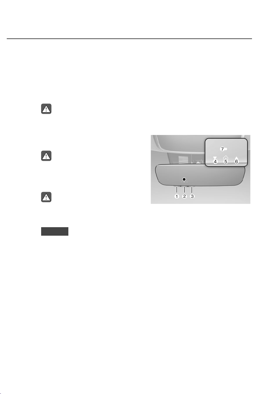
5-61
05
MIRRORS
Inside Rearview Mirror
Before driving your vehicle, check to
see that your inside rearview mirror is
properly positioned. Adjust the rearview
mirror so that the view through the rear
window is properly centered.
WARNING
Make sure your line of sight is not
obstructed. Do not place objects in the
rear seat, cargo area, or behind the rear
headrests which could interfere with
your vision through the rear window.
WARNING
To prevent serious injury during an
accident or deployment of the air bag,
do not modify the rearview mirror and
do not install a wide mirror.
WARNING
NEVER adjust the mirror while driving.
This may cause loss of vehicle control
resulting in an accident.
NOTICE
When cleaning the mirror, use a paper
towel or similar material dampened
with glass cleaner. Do not spray glass
cleaner directly on the mirror as this
may cause the liquid cleaner to enter
the mirror housing.
Electrochromic mirror (ECM) with
HomeLink® system
Your vehicle may be equipped with
a Gentex Automatic-Dimming Mirror
with an Integrated HomeLink® Wireless
Control System.
During nighttime driving, this feature
will automatically detect and reduce
rearview mirror glare. The HomeLink®
Universal Transceiver allows you to
activate your garage door(s), electric
gate, home lighting, etc.
ORS052039N
ORS052039N
M HomeLink Channel 1
N HomeLink Channel 2
O HomeLink Channel 3
P
Garage Door Opener Status Indicator:
Closing or Closed
Q HomeLink Operation Indicator
R
Garage Door Opener Status Indicator:
Opening or Opened
S HomeLink User Interface Indicator

5-62
Convenience Features
$XWRPDWLF'LPPLQJ1LJKW9LVLRQ6DIHW\
196
®
) Mirror (if equipped)
The NVS® Mirror automatically reduces
glare by monitoring light levels in the
front and the rear of the vehicle. Any
object that obstructs either light sensor
will degrade the automatic dimming
control feature.
)RUPRUHLQIRUPDWLRQUHJDUGLQJ196p
mirrors and other applications, refer to
the Gentex website:
www.gentex.com
Your mirror will automatically dim
upon detecting glare from the vehicles
traveling behind you.
The mirror defaults to the ON position
each time the vehicle is started.
Integrated HomeLink
®
:LUHOHVV&RQWURO
System
The HomeLink® Wireless Control System
provides a convenient way to replace
up to three hand held radio-frequency
transmitters used to activate compatible
devices such as gate operators, garage
door openers, entry door locks, security
systems, and home lighting.
NOTICE
+RPH/LQNpRSHUDWHVZKLOHWKHLJQLWLRQ
switch is in the ACC or ON position
for safety reasons. It is to prevent
unintentional security problems from
happening when the vehicle is parked
outside the garage.
WARNING
%HIRUHSURJUDPPLQJ+RPH/LQNpWRD
garage door opener or gate operator,
make sure people and objects are out
of the way of the device to prevent
potential harm or damage. Do not
XVHWKH+RPH/LQNpZLWKDQ\JDUDJH
door opener that lacks the safety
stop and reverse features required
by U.S. federal safety standards (this
includes any garage door opener model
manufactured before April 1, 1982).
A garage door that cannot detect an
object - signaling the door to stop and
reverse - does not meet current U.S.
federal safety standards. Using a garage
door opener without these features
increases the risk of serious injury or
death.
)RUPRUHLQIRUPDWLRQFRQWDFW
+RPH/LQNpDWZZZKRPHOLQNFRPRU
call Home-Link customer support at
1-800-355-3515.
It is also recommended that a new
battery be replaced in the handheld
transmitter of the device being trained
WR+RPH/LQNpIRUTXLFNHUWUDLQLQJDQG
accurate transmission of the radio
frequency.
1. Programming HomeLink
®
The following steps show how to
program HomeLink. If you have any
questions or are having difficulty
programming your HomeLink buttons,
refer to the HomeLink website or call the
HomeLink customer support toll-free
number. Do this, before going back to
the dealer who sold you the car.
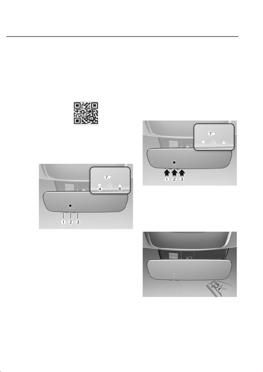
5-63
05
• Visit the HomeLink website at: www.
homelink.com. Then at the top of the
page, choose your vehicle make. Then
watch the You Tube video, and/or
access additional website information.
• If you choose to access the website
via your cell phone, scan the QR code.
• Or, call HomeLink customer support
at 1-800-355-3515 (Please have the
vehicle make/model AND the opener
device make/model readily available.)
1) Programming Preparation
ORS052306N
ORS052306N
1. When programming a garage door
opener, it is advised to park the
vehicle outside of the garage.
2. It is recommended that a new battery
be placed in the handheld transmitter
of the device being programmed to
HomeLink for quicker training and
accurate transmission of the radio-
frequency signal.
3. Place the ignition switch to the ACC
(Accessory) position for programming
of HomeLink.
ȹ 3URJUDPPLQJD1HZ+RPH/LQNp
ORS052307N
ORS052307N
1. Press and release the HomeLink
button (1), (2) or (3), you would like
to program. The HomeLink indicator
light (7) will flash orange slowly (if
not, perform the steps of “Erasing
HomeLink Buttons” section, and start
over).
OJX1050295N
OJX1050295N
2. Position the garage door opener
remote 1 – 3 inches (2 – 8 cm) away
from the HoleLink buttons.
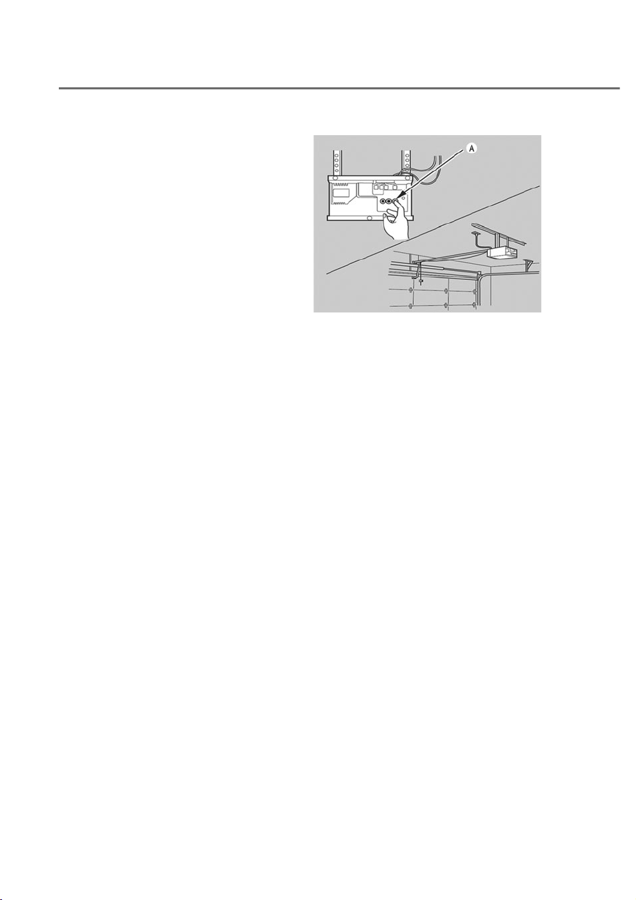
5-64
Convenience Features
3. While the HomeLink indicator light S
is flashing orange, press and hold the
hand-held remote button. Continue
pressing the handheld remote button
until the HomeLink indicator light S
light changes from orange to green.
You may now release the handheld
remote button.
4. Wait until your garage door comes
to a complete stop, regardless of
position, before proceeding to the
next steps.
5. Press and release the HomeLink
button you are programming and
observe the indicator light.
• If the indicator light remains solid
green, your device should operate
when the HomeLink button is
pressed. At this point, if your device
operates, programming is complete.
• If the indicator light rapidly
flashes green, firmly press, hold
for two seconds and release the
HomeLink button up to three times
in a row slowly to complete the
programming process. Do not press
the HomeLink button rapidly. At
this point if your device operates,
programming is complete. If the
device does not operate, continue
with step 6.
6. At the garage door opener motor,
(security gate motor, etc.) locate the
“Learn”, “Smart”, “Set” or “Program”
button. This can usually be found
where the hanging antenna wire is
attached to the motor-head unit (see
the device’s manual to identify this
button). The name and color of the
button may vary by manufacturer.
ODL3A040504
ODL3A040504
à A ladder and/or second person may
simplify the following steps.
7. Firmly press and release the “Learn”,
“Smart”, “Set” or “Program” button.
You now have up to 30 seconds in
which to complete the next step.
8. Return to the vehicle and firmly press,
hold for two seconds and release,
the HomeLink button up to three
times in a row slowly. Do not press
the HomeLink button rapidly. As soon
as you see the garage door start to
move, stop pressing any buttons
until a few seconds after the garage
door has come to a complete stop,
regardless of position. At this point,
programming is complete and your
device should operate when the
HomeLink button is pressed and
released.

5-65
05
3) Two-Way Communication
3URJUDPPLQJ)RUVHOHFWJDUDJHGRRU
openers)
If your garage door opener has the
‘myQ’ logo on its side, your opener
likely has Two-Way Communication
capability. HomeLink has the capability
to establish Two-Way Communication
with your garage door opener. HomeLink
can receive and display “closing”
or “opening” status messages from
compatible garage door openers. At
any time, Home-Link can also recall
and display the last recorded status
communicated by the garage door
opener to indicate your garage door
being “closed” or “opened”.
To check if your garage door opener is
compatible with this feature, refer to
www.homelink.com/compatible/Two-
way-Communication. If your garage
door opener has this functionality, AND
the Two-Way Communication indicators
P, R in the mirror appear while the
garage door is opening/closing, then
no further steps are needed. Two-Way
Communication Programming is already
complete. However, if your garage door
opener has this functionality, AND the
Two-Way Communication indicators P,
R in the mirror DO NOT appear while
the garage door is opening/closing, use
the following instructions to enable this
functionality.
1. In your vehicle, press and hold the
programmed HomeLink button for 2
seconds, then release. Confirm that
the garage door is moving. AFTER it
stops, you will have one minute to
complete the following steps:
à A ladder and/or second person may
simplify the following steps.
2. On your garage door opener in your
garage, locate the “Learn” button
(usually near where the hanging
antenna wire is attached to the garage
door opener). If there is difficulty
locating this button, reference the
device’s owner’s manual.
3. Press and release the “Learn” button.
4. A light on your garage door opener
may flash, and your Two-Way
Communication indicators P, R in
your vehicle may flash, confirming
completion of the process.
5. Return to the vehicle and firmly
press and release the programmed
HomeLink button to activate
your garage door. The Two-Way
Communication indicators P, R flash
in orange when the door is moving.
Do not make any additional button
presses until AFTER the garage door
has come to a complete stop.
6. Your Two-Way Communication
programming is now complete.
Information
If your garage door opener has Two-
:D\&RPPXQLFDWLRQIXQFWLRQDOLW\
it is possible for HomeLink to stop
functioning the garage door shortly
after initial programming, IF the Two-
:D\&RPPXQLFDWLRQ3URJUDPPLQJ
wasn’t properly completed. This
usually happens after the first 10 times
a programmed HomeLink button is
pressed. If you experience this, completing
the “Programming a New HomeLink
%XWWRQ´DQG³7ZR:D\&RPPXQLFDWLRQ
Programming” will restore door
operation.

5-66
Convenience Features
4) Canadian Programming
Canadian radio-frequency laws require
transmitter remote signals to “time-
out” (or quit) after a couple seconds of
transmission, which may not be long
enough for HomeLink to pick up the signal
during programming.
If you live in Canada or you are having
difficulties programming a gate operator
or garage door opener by using the
programming procedures, replace
“Programming a New HomeLink Button”
step 3 with the following:
While the HomeLink indicator light S is
flashing orange, press and release (“cycle”)
your device’s handheld remote every two
seconds until the HomeLink indicator light
S changes from orange to green. You may
now release the hand-held remote button.
Then proceed with “Programming a New
HomeLink Button” step 4.
2SHUDWLQJ+RPH/LQN
®
ȸ 2SHUDWLQJ+RPH/LQNp
ORS052307N
ORS052307N
1. Press and release the desired
programmed HomeLink button (M, N
or O).
Information
The HomeLink indicator S should
light green, solid or flashing, and your
programmed device should operate.
If your device does not operate, the
HomeLink programming was not
successful, and you’ll need to reprogram
the button.
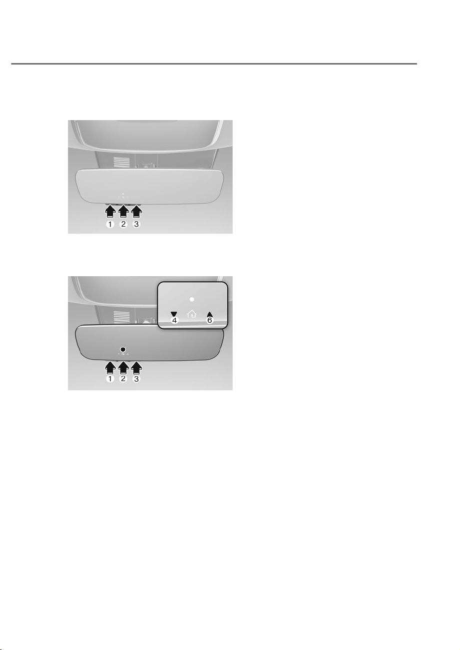
5-67
05
2) Two-Way Communication Display
Behavior
OJWEV051283N
OJWEV051283N
1. Press and release one of the
programmed HomeLink buttons (M,
N or O).
ORS052309N
ORS052309N
2. The indicator P and R operates as
below, if your garage door opener
has Two-Way Communication
functionality.
• If the indicator P flashes in Orange,
it indicates that the garage door is
“Closing”.
• The indicator P turns solid green once
the garage door has closed.
• If the indicator R flashes in Orange,
it indicates that the garage door is
“Opening”.
• The indicator R turns solid green once
the garage door has fully opened.
• If the indicator P or R does not
turn to green, it indicates that the
last status of garage door was not
received properly. The HomeLink
mirror tries to receive the last known
status of the garage door for a few
seconds.
3) Recalling Garage Door Status
HomeLink mirror with Two-Way
Communication provides a way to view
the last stored message from the garage
door opener. In order to recall the last
known status of the last activated device,
press the buttons “1 and 2” OR “2 and 3”
simultaneously.
• If the indicator P appears solid Green,
it indicates that the last activated
device was “closed” properly.
• If the indicator R appears solid Green,
it indicates that the last activated
device was “open” properly.
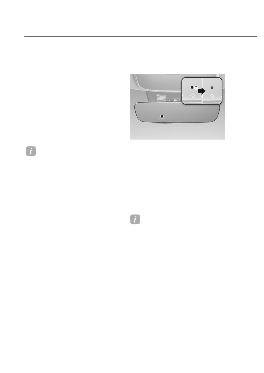
5-68
Convenience Features
3. Erasing HomeLink® Buttons
1) Erasing and Reprogramming a Single
+RPH/LQNp%XWWRQ
1. Press and hold the desired HomeLink
button you want to re-program. DO
NOT release the button.
2. The HomeLink indicator light S will
illuminate solid green. Release the
button as soon as the HomeLink
indicator light S begins to flash
orange, usually about 20 seconds.
3. Proceed with the steps in the
“Programming a New HomeLink
Button” section.
Information
If you do not complete the re-
programming of a new device to the
button, it will revert to the previously
stored programming.
2) The following instructions will erase
$//+RPH/LQNpSURJUDPPLQJIURP
ALL buttons:
ORS052310N
ORS052310N
1. Press and hold the buttons M and O
simultaneously.
2. The HomeLink indicator light S will
illuminate solid Orange for about 10
seconds.
3. Release the buttons once the
HomeLink indicator light S changes
to Green and flashes rapidly.
4. Now all three HomeLink buttons
M, N and O are cleared of any
programming.
Information
HomeLink
®
and the HomeLink
®
House
logo are registered trademarks of Gentex
&RUSRUDWLRQ
The myQ logo is a registered trademark of
7KH&KDPEHUODLQ*URXS,QF

5-69
05
)&&86$DQG,6('&DQDGD
This device complies with FCC rules
part 15 and Innovation, Science, and
Economic Development Canada RSS-
210. Operation is subject to the following
two conditions: (1) This device may not
cause harmful interference, and (2) This
device must accept any interference that
may be received including interference
that may cause undesired operation.
WARNING: The transmitter has been
tested and complies with FCC and
ISED rules. Changes or modifications
not expressly approved by the party
responsible for compliance could void
the user’s authority to operate the
device.
This equipment complies with FCC
and ISED radiation exposure limits set
forth for an uncontrolled environment.
End Users must follow the specific
operating instructions for satisfying RF
exposure compliance. This transmitter
must be at least 20cm from the user and
must not be co-located or operating in
conjunction with any other antenna or
transmitter.
)&&+WDWV8QLVHW,6('&DQDGD
Cet appareil est conforme aux
règlements de la FCC, section 15, et
au CNR-210 d’Innovation, Sciences et
Dhveloppement économique Canada. Le
fonctionnement est assujetti aux deux
conditions suivantes : (1) cet appareil ne
doit pas causer d’interférences nuisibles
et (2) cet appareil doit accepter toute
interférence reçue, y compris celle qui
pourrait entraîner un dysfonctionnement.
MISE EN GARDE : L’émetteur a subi des
tests et est conforme aux règlements de
la FCC et d’ISDE. Les changements ou
modifications non approuvés explicitement
par la partie responsable de la conformité
pourraient rendre caduque l’autorisation de
l’utilisateur de se servir du dispositif.
Cet appareil est conforme aux limites
d’exposition aux radiations de la FCC et
d’ISDE établies pour un environnement
non contrôlé. Les utilisateurs finaux doivent
respecter les instructions d’utilisation
spécifiques pour satisfaire aux exigences
de conformité aux expositions de RF.
L’émetteur doit se trouver à 20 cm au
minimum de l’utilisateur et ne doit pas
être situé au même endroit que tout autre
émetteur ou antenne ni fonctionner avec
un autre émetteur ou antenne.
Méjico
La operación de este equipo está sujeta
a las siguientes dos condiciones: (1) es
posible que este equipo o dispositivo
pueda no causar interferencia dañina, y
(2) este dispositivo o dispositivos deben
aceptar cualquier interferencia, que
incluye la interferencia que puede causar
su operación no deseada.
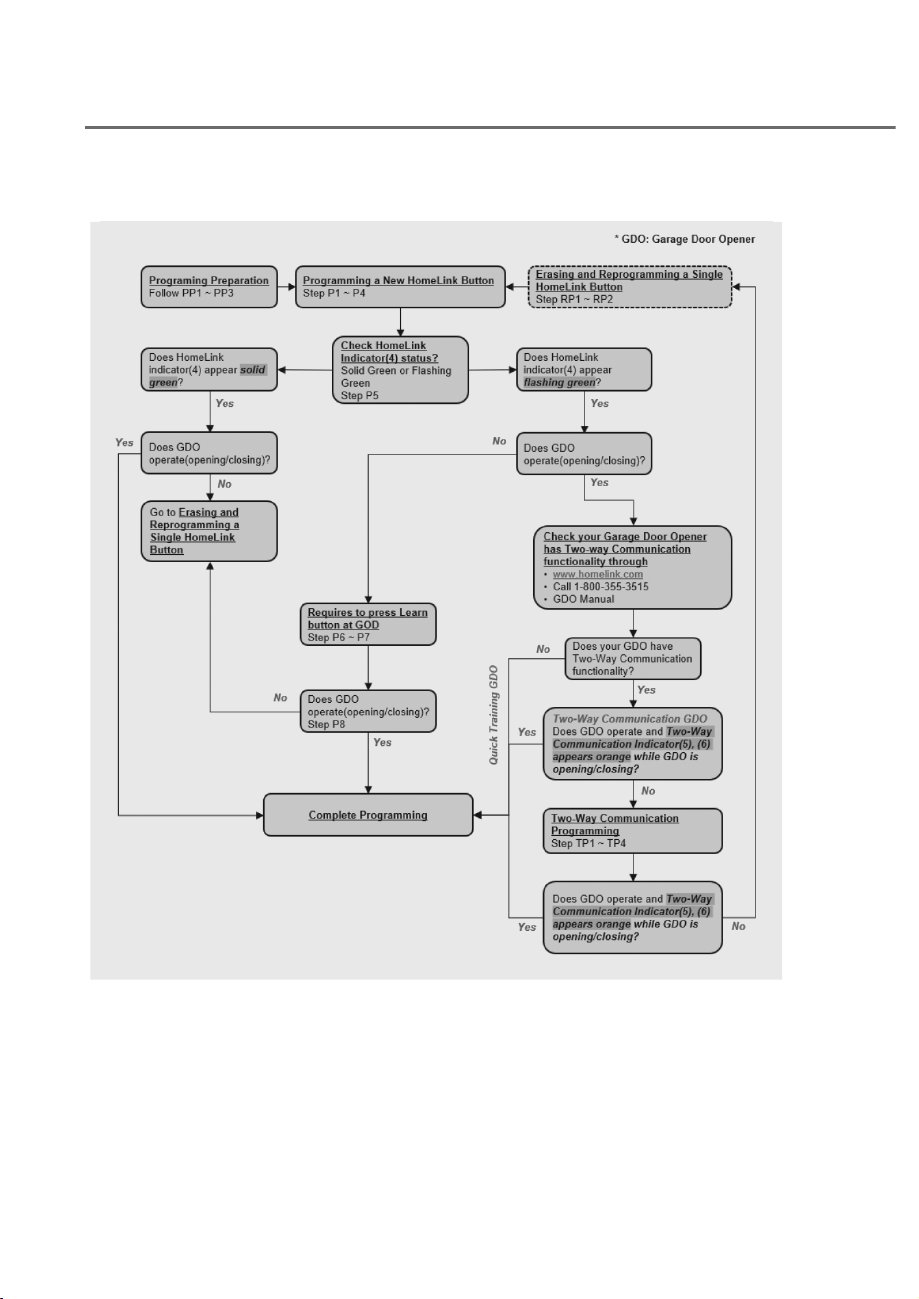
5-70
Convenience Features
+RPH/LQN3URJUDPLQJ)ORZ&KDUW
ODL3A040518
ODL3A040518
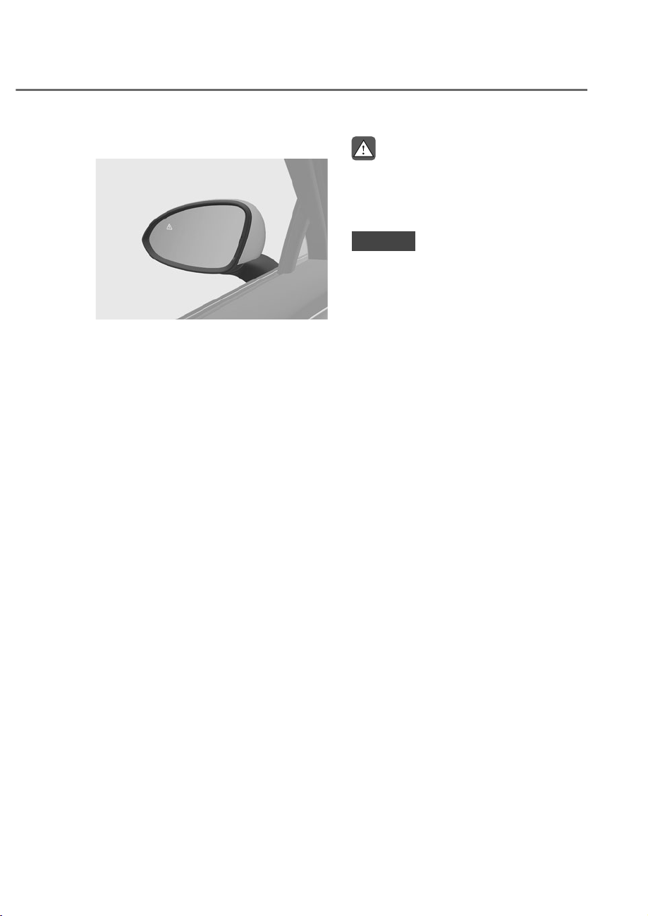
5-71
05
Side View Mirrors
ORS051040
ORS051040
Your vehicle is equipped with both
left-hand and right-hand side view
mirrors. The mirrors can be adjusted
remotely with the remote switch. The
side view mirrors can be folded to help
prevent damage when going through
an automatic car wash or when passing
through a narrow street.
The right side view mirror is convex.
Objects seen in the mirror are closer than
they appear.
Use the inside side view mirror or look
back directly to determine the actual
distance of other vehicles prior to
changing lanes.
Make sure to adjust the side view mirrors
to your desired position before you begin
driving.
WARNING
Do not adjust or fold the side view
mirrors while driving. This may cause
loss of vehicle control resulting in an
accident.
NOTICE
• Do not scrape ice off the mirror face;
this may damage the surface of the
glass.
• If the mirror is jammed with ice, do
not adjust the mirror by force. Use
an approved de-icer (not radiator
antifreeze) spray, or a sponge or soft
cloth with very warm water, or move
the vehicle to a warm place and
allow the ice to melt.
• Do not clean the mirror with harsh
abrasives, fuel or other petroleum
based cleaning products.
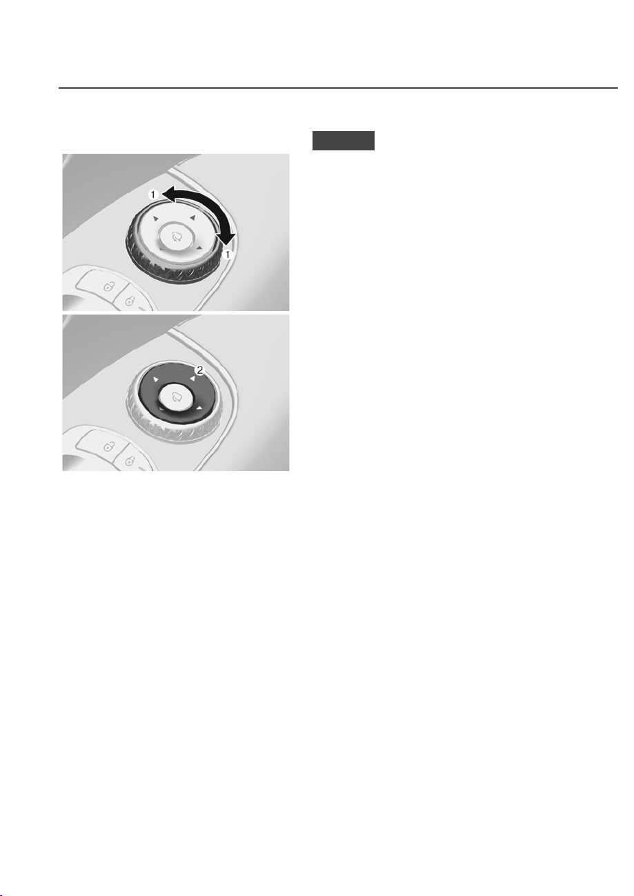
5-72
Convenience Features
Adjusting the rearview mirrors
ORS051042
ORS051042
ORS051041
ORS051041
Adjusting the rearview mirrors:
1. Turn the outer ring to the left or right
M to select the rearview mirror you
would like to adjust.
2. Use the mirror adjustment control
switch N to position the selected
mirror up, down, left or right.
3. After adjustment, return the outer
ring to the center position to prevent
inadvertent adjustment.
NOTICE
• The mirrors stop moving when
they reach the maximum adjusting
angles, but the motor continues to
operate while the switch is pressed.
Do not press the switch longer than
necessary, because this can damage
the motor.
• Do not attempt to adjust the
rearview mirrors by hand, because
this can damage the motor.
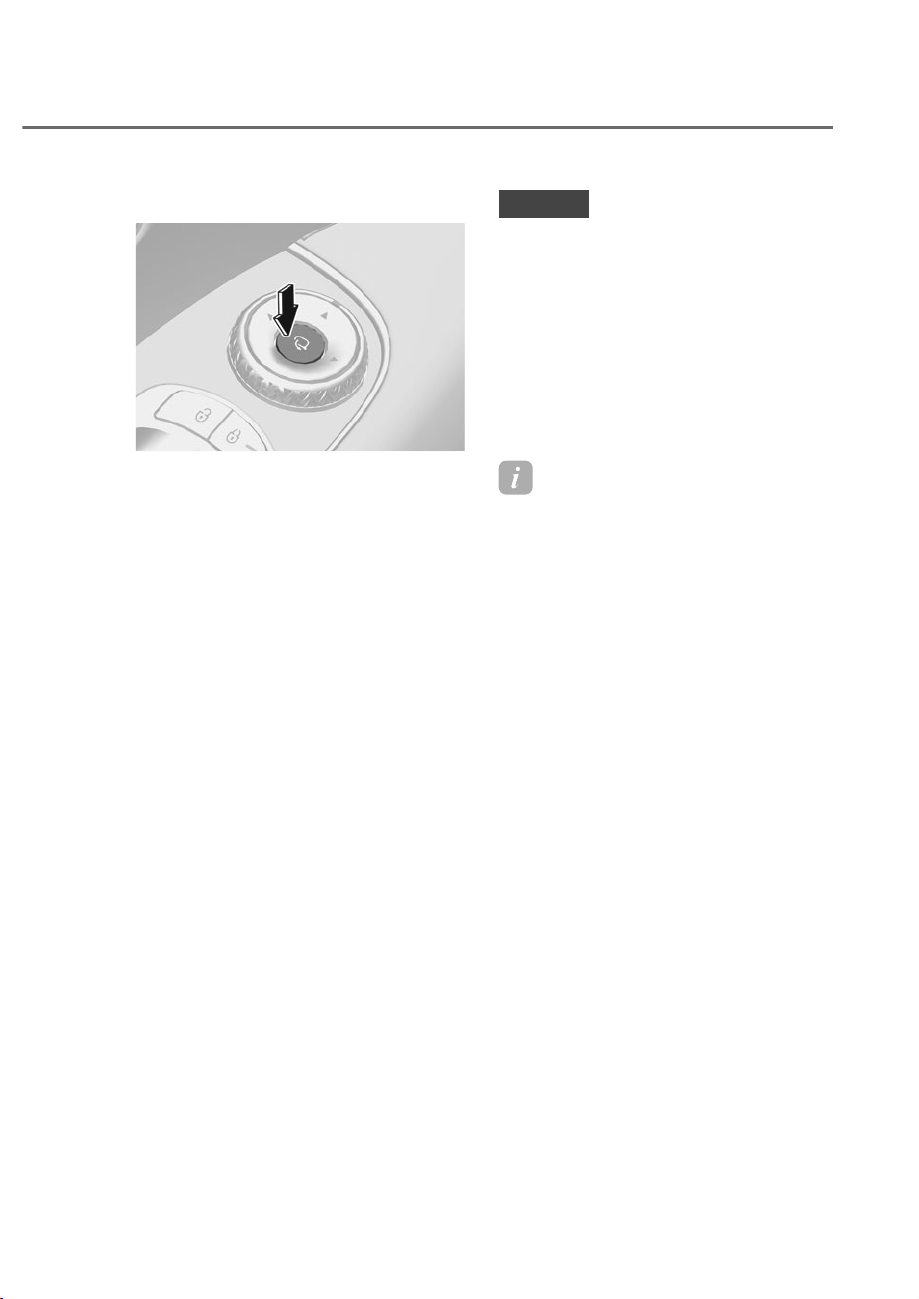
5-73
05
Folding the rearview mirrors
ORS051043
ORS051043
The rearview mirrors can be folded or
unfolded by pressing the button.
Infotainment system setting
• On door unlock
,Iȁ6HWXSɌ9HKLFOHɌ:HOFRPH0LUURU
/LJKWɌ2Q'RRU8QORFNȂLVVHOHFWHG
from the Settings menu in the
infotainment system screen,
- The mirror will fold or unfold when
the door is locked or unlocked by
the smart key.
- The mirror will fold or unfold when
the door is locked or unlocked by
the touch sensor on the outside
door handle.
• On driver approach
,Iȁ6HWXSɌ9HKLFOHɌ:HOFRPH0LUURU
/LJKWɌ2Q'ULYHU$SSURDFKȂLV
selected from the Settings menu in
the infotainment system screen, the
mirror will unfold when the vehicle
is approached with the smart key in
possession.
See additional information in supplied
Infotainment Manual.
NOTICE
• The electric type side view mirror
operates even though the Engine
6WDUW6WRSEXWWRQLVLQWKH2))
position. However, to prevent
unnecessary battery discharge, do
not adjust the mirrors longer than
necessary while the engine is not
running.
• Do not fold the electric type side
view mirror by hand. It could cause
motor failure.
Information
• 2QGRRUXQORFNPXVWEHVHWLQWKH
LQIRWDLQPHQWV\VWHPWRVHOHFW2Q
driver approach.
• For the safety reasons, the side view
mirrors do not fold when vehicle speed
is above 9 mph (15 km/h).
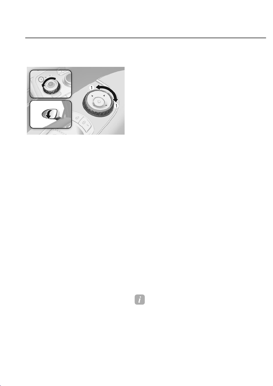
5-74
Convenience Features
Reverse Parking Aid (if equipped)
ORS051044
ORS051044
When the gear is shifted to the R
(Reverse) position, the side view mirror(s)
will rotate downwards to aid with driving
in reverse.
The position of the side view mirror outer
ring M determines whether or not the
mirrors will move:
How it works
• When the outer ring is either in the
left side or right side, both side view
mirrors will move.
• If the outer rings is in the center
position, both side view mirrors will
not move.
The side view mirrors will automatically
revert to their original positions if any of
the following occur:
• The Engine Start/Stop button is
pressed to either the OFF position or
the ACC position.
• The gear is shifted to any position
except R (Reverse).
Reverse parking aid user settings
mode
You may change the angle of the side
view mirror if it is difficult to see the side
view with the basic downward mirror
angle provided when reversing.
When the vehicle is first delivered, the
set downward angle of the left and right
side view mirror are different to ensure
driver visibility.
1. Make sure the vehicle is stopped.
2. Depress the brake pedal and shift the
gear to R (Reverse). When the outer
ring is either in the left position or
right position, both side view mirror
angle will move downward to the
basic set position.
3. Rotate the outer ring either to the left
position or right position to select
the side view mirror you would like
to adjust. Then press “ź, Ÿ, Ż, Ź”
switch to adjust the side view mirror
to the desired angle.
4. After adjusting the angle to save the
adjusted side view mirror angle, shift
the gear to another position other
than R (Reverse), or rotate the outer
ring to the center position.
5. Set the other side view mirror
following the above procedure 1 to 4.
Resetting reverse parking aid user
settings mode
To change the side view mirror angle
back to the basic angle, shift the gear to
R (Reverse), and adjust the mirror angle
higher than when the gear is in P (Park),
N (Neutral) and D (Drive).
Information
When changing the angle of both side
view mirrors, it is recommended to change
the angle one side at a time following the
procedure 1 to 4.
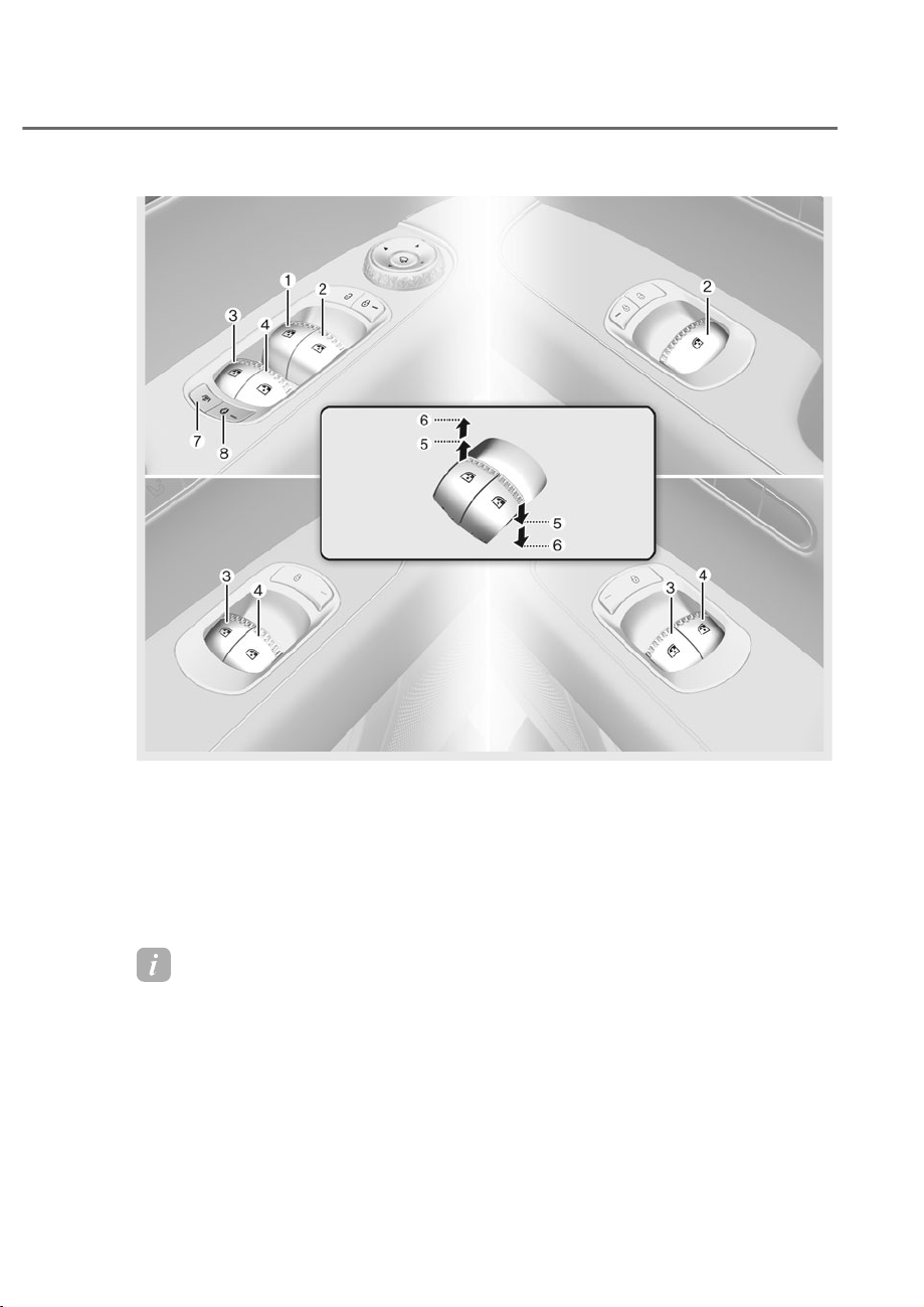
5-75
05
ORS052001L
ORS052001L
WINDOWS
M Driver’s door power window switch
N
Front passenger’s door power window
switch
O Rear door (left) power window switch
P Rear door (right) power window switch
Q Window opening and closing
R Automatic power window
S Rear side window sunshades
T
Power window lock switch/Electronic
child safety lock
Information
If the rear passenger seat sunshades are equipped, you can fold/unfold the sunshades with
the window switch. For details, see "Rear Side sunshades" in chapter 5.
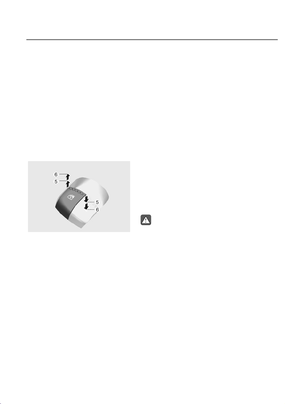
5-76
Convenience Features
Power Windows
The Engine Start/Stop button must be
in the ON position to be able to raise
or lower the windows. Each door has a
Power Window switch to control that
door’s window. The driver has a Power
Window Lock button which can block the
operation of rear passenger windows.
The power windows will operate for
approximately 3 minutes after the Engine
Start/Stop button is in the ACC or OFF
position. However, if the front doors are
opened, the Power Windows will not
operate even within the 3 minute period.
Window opening and closing
ORS051046
ORS051046
To open:
Press the window switch down to the
first detent position Q. Release the
switch when you want the window to
stop.
To close:
Pull the window switch up to the first
detent position Q. Release the window
switch when you want the window to
stop.
Auto up/down window
Pressing or pulling up the power window
switch momentarily to the second
detent position R completely lowers or
lifts the window even when the switch
is released. To stop the window at the
desired position while the window is in
operation, pull up or press down and
release the switch.
Resetting the power windows
If the power windows do not operate
normally, the automatic power window
system must be reset as follows:
1. Press the Engine Start/Stop button to
the ON position.
2. Close the window and continue
pulling up on the power window
switch for at least one second.
If the power windows do not operate
properly after resetting, have the system
inspected by an authorized retailer of
Genesis Branded products.
WARNING
The automatic reverse feature doesn't
activate while resetting the power
window system. Make sure body parts
or other objects are safely out of the
way before closing the windows to
avoid injuries or vehicle damage.
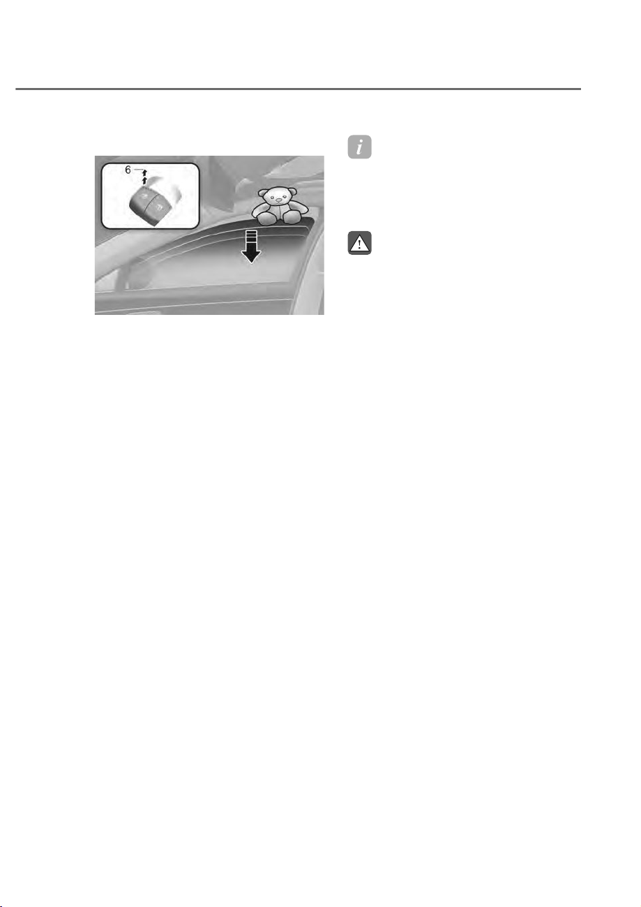
5-77
05
Automatic reverse
ORS051047
ORS051047
If a window senses any obstacle while it
is closing automatically, it will stop and
lower approximately 12 in. (30 cm) to
allow the object to be cleared.
If the window detects the resistance
while the power window switch is
pulled up continuously, the window
will stop upward movement then lower
approximately 1 in. (2.5 cm).
If the power window switch is pulled
up continuously again within 5 seconds
after the window is lowered by the
automatic window reverse feature,
the automatic window reverse will not
operate.
Information
The automatic reverse feature is only
active when the “Auto Up” feature is used
by fully pulling up the switch to the second
detent.
WARNING
Make sure body parts or other objects
are safely out of the way before closing
the windows to avoid injuries or vehicle
damage.
Objects less than 0.16 in. (4 mm) in
diameter caught between the window
glass and the upper window channel
may not be detected by the automatic
reverse window and the window will
not stop and reverse direction.
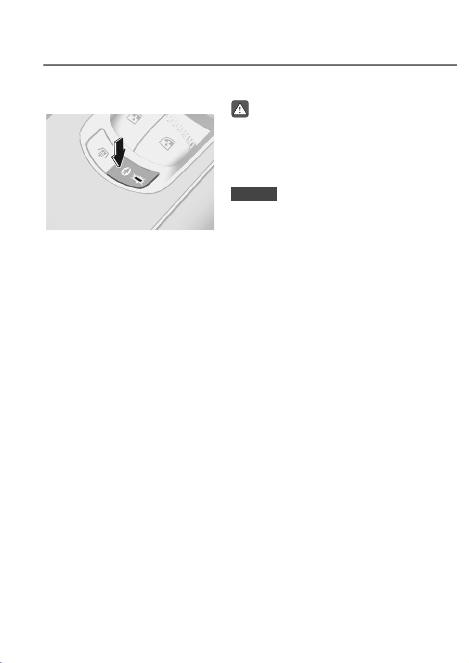
5-78
Convenience Features
Power window lock button
ORS051031
ORS051031
The driver can disable the power window
switches on the rear passenger doors by
pressing the power window lock button.
When the power window lock button is
pressed:
• The rear passenger control will not
be able to operate the rear passenger
power window.
• Note that the front passenger control
is still able to operate the front
passenger window, and that the driver
master control can still operate all the
power windows.
WARNING
Do not allow children to play with the
power windows. Keep the driver’s
door power window lock button in the
LOCK position. Serious injury or death
can result from unintentional window
operation by a child.
NOTICE
• To prevent possible damage to the
power window system, do not open
or close two windows or more at the
same time. This will also ensure the
longevity of the fuse.
• Never try to operate the main
switch on the driver’s door and the
individual door window switch in
opposite directions at the same time.
If this is done, the window will stop
and cannot be opened or closed.
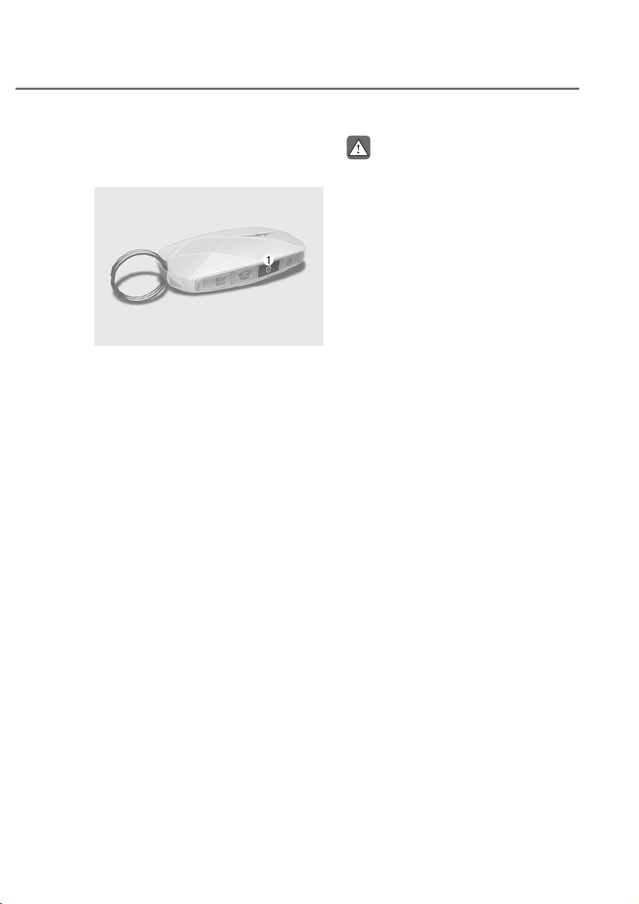
5-79
05
5HPRWH:LQGRZ2SHQ)HDWXUH
(Remote Window Control) (if
equipped)
ORS052048N
ORS052048N
You can open the window remotely with
the smart key.
1. Press and hold the door unlock button
M for over 3 seconds, while the engine
is turned off.
• Rear doors are unlocked and
windows are completely opened.
• If you release the button while the
window is opening, the window will
stop operating.
CAUTION
• If the distance between the vehicle
and your smart key changes while
the window is being opened or
closed, the window may stop
operating. Do not stand too far away
from the vehicle when remotely
opening or closing the window.
• Note that the doors are also unlocked
when you open the window with the
remote opening feature.
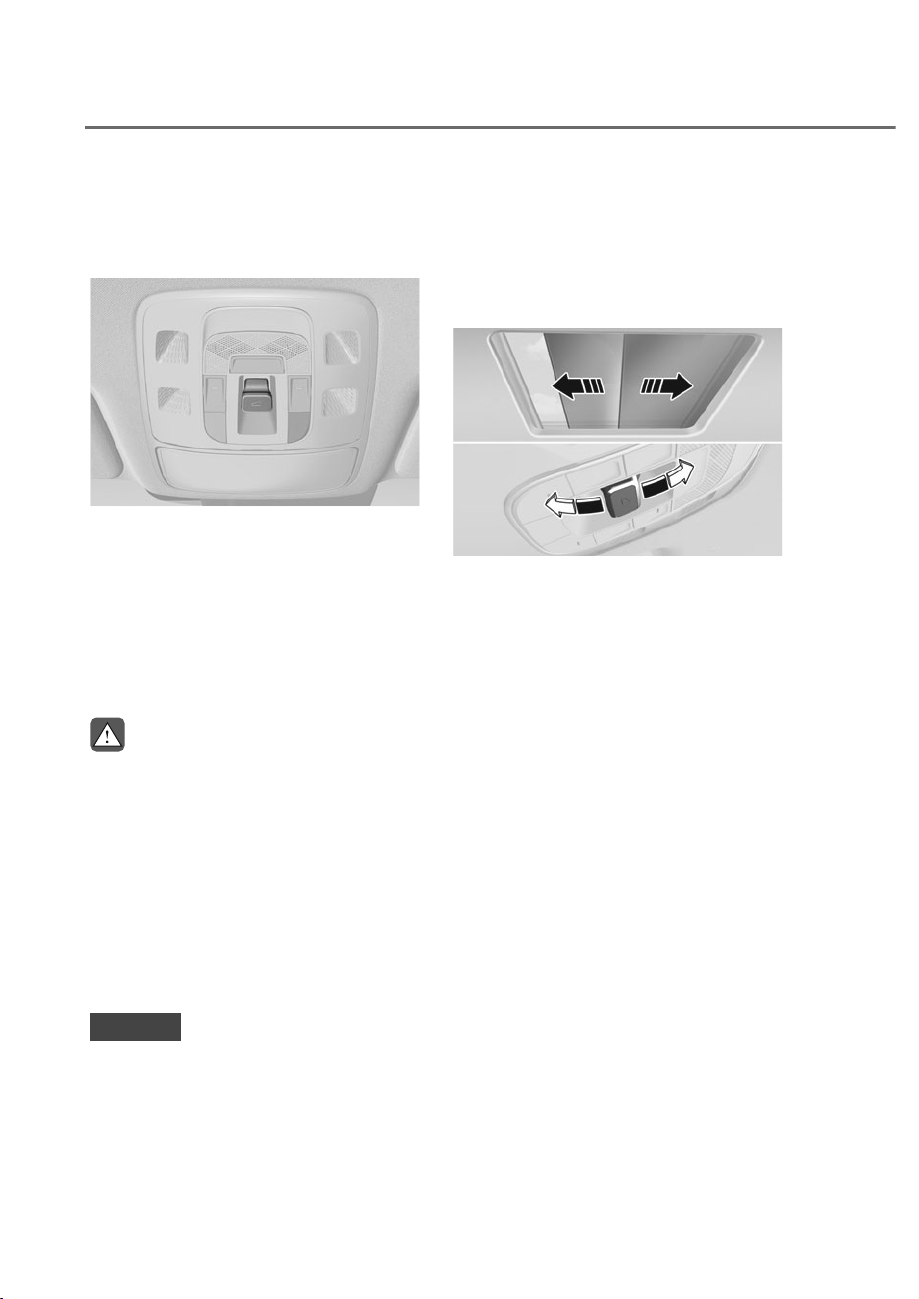
5-80
Convenience Features
If your vehicle is equipped with a
sunroof, you can slide or tilt your sunroof
with the sunroof switch located on the
overhead console.
ORS052049N
ORS052049N
The sunroof can only be operated when
the Engine Start/Stop button is in the ON
or START position.
The sunroof can be operated for
approximately 3 minutes after the Engine
Start/Stop button is in the ACC or OFF
position. However, if the front door is
open, the sunroof cannot be operated
even within the 3minute period.
WARNING
• Adjust the sunroof or sunshade when
your vehicle stops. This could result
in loss of control and an accident
that may cause injury, or property
damage.
• Do not leave the engine running
and the key in your vehicle with
unsupervised children. Unattended
children could operate the sunroof,
which could result in serious injury.
• Do not sit on the top of the vehicle. It
may cause injury or vehicle damage.
NOTICE
Do not operate the sunroof when roof
bars are installed on the vehicle or
when there is luggage on the roof.
Power Sunshade
Use the power sunshade to block direct
sunlight coming through the sunroof
glass.
Using front seat power sunshade
ORS051050
ORS051050
• Push the sunroof switch rearward to
the first detent position, the power
sunshade automatically slides open.
• Push the sunroof switch forward to
the first detent position, the power
sunshade automatically closes.
However, if the sunroof glass is open,
the glass will close first.
To stop the power sunshade at any point,
push the sunroof switch in any direction.
3$125$0,&681522)ʚ,)(48,33('ʛ
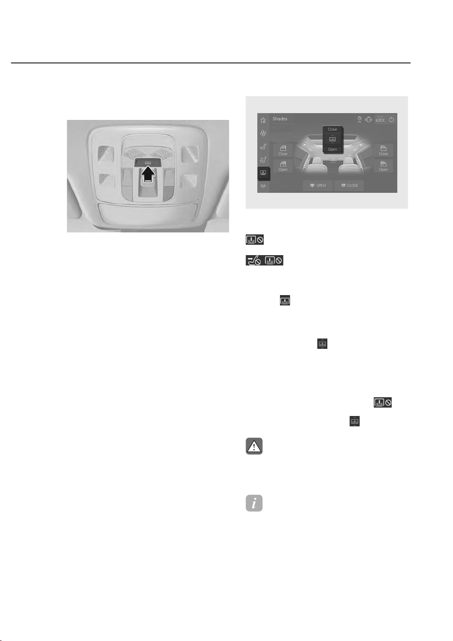
5-81
05
Using the rear seat power sunshade
(if equipped)
ORS052051N
ORS052051N
2SHUDWLQJUHDUVHDWVXQVKDGHVZLWFK
Press the switch to open the rear seat
power sunshade. Press again to close the
sunshade.
The sunroof will not be opened.
ORS051249L
ORS051249L
2SHUDWLQJUHDUVHDWVXQVKDGHIURP
touchscreen
: Stops the rear seat power
sunshade from opening or closing.
: Stops the seat mode and
the rear seat power sunshade from
operating.
1. Press
from the left side menu of
the armrest touchscreen.
• Sunshade adjusting screen is
displayed.
2. Press and slide
in the center of
the display upward or downward to
completely raise or lower the power
sunshade.
• To adjust the power sunshade to the
desired position when the sunshade
is opening or closing, press
on the upper right part of the
touchscreen or press
again.
CAUTION
Do not push or pull the power sunshade
with your hands. The sunshade may be
damaged and cause malfunction.
Information
• Wrinkles formed on the power
sunshade are normal due to material
characteristic.
• While the power sunshade is opened
or being operated, the mood lighting
turns off.
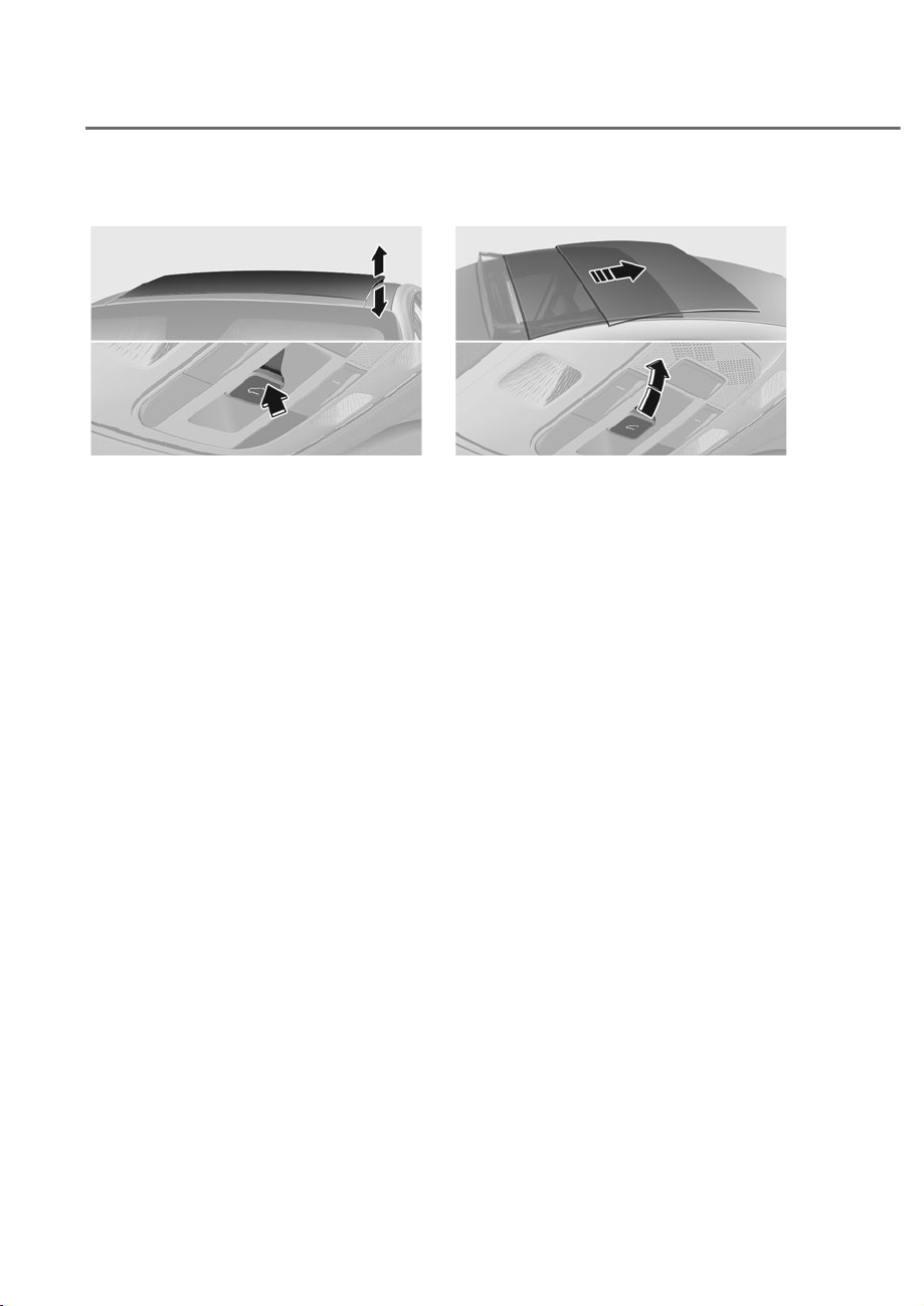
5-82
Convenience Features
Tilt Open/Close
ORS052052N
ORS052052N
• Push the sunroof switch upward, the
sunroof glass tilts open. However, if
the power sunshade is closed, the
sunshade will open first.
• Push the sunroof switch upward
or forward when the sunroof glass
is tilt opened, the sunroof glass
automatically closes.
To stop the sunroof movement at any
point, push the sunroof switch in any
direction.
Slide Open/Close
ORS052053N
ORS052053N
• Push the sunroof switch rearward to
the first detent position, the sunroof
glass opens. However, if the power
sunshade is closed, the power
sunshade will open first.
Push the sunroof switch forward to
the first detent position, the sunroof
glass closes. However, if the sunroof
glass is closed, the power sunshade
will close.
• Push the sunroof switch forward
or rearward to the second detent
position, the power sunshade and
sunroof glass operate automatically
(auto slide feature).
To stop the sunroof movement at any
point, push the sunroof switch in any
direction.
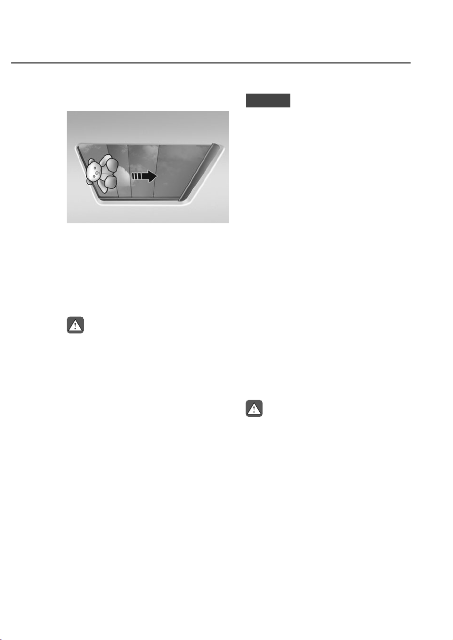
5-83
05
Automatic Reverse
ORS051054
ORS051054
If the power sunshade or sunroof glass
senses any obstacle while it is closing
automatically, it will reverse direction
then stop at a certain position.
The auto reverse feature may not work if
an object thin or soft is caught between
the sliding power sunshade or sunroof
glass and sunroof sash.
WARNING
• Make sure heads, hands, arms or
any other body parts or objects are
out of the way before operating the
sunroof. Body parts or objects may
get caught causing injuries or vehicle
damage.
• Never deliberately use your body
parts to test the automatic reverse
feature. The power sunshade or
sunroof glass may reverse direction,
but there is a risk of injury.
NOTICE
• Do not continue to push the sunroof
switch after the sunroof is fully
opened, closed, or tilted. Damage to
the sunroof motor could occur.
• Continuous operations such as slide
open/close, tilt open/close, etc. may
cause the motor or sunroof system to
malfunction.
• Regularly remove any accumulated
dust on the sunroof rail.
• Dust accumulated between the
sunroof and roof panel can make
noise. Open the sunroof and remove
dust regularly using a clean cloth.
• Do not try to open the sunroof when
the temperature is below freezing
or when the sunroof is covered
with snow or ice. The sunroof may
not work properly and may break if
opened by force.
• Do not open or drive with the sunroof
glass open immediately after rain or
washing the vehicle. Water may wet
the interior of the vehicle.
• Do not extend any luggage outside
the sunroof while driving. Vehicle
damage may occur if the vehicle
suddenly stops.
WARNING
Do not extend your head, arms, body
parts or objects outside the sunroof
while driving. Injuries may occur if the
vehicle suddenly stops.
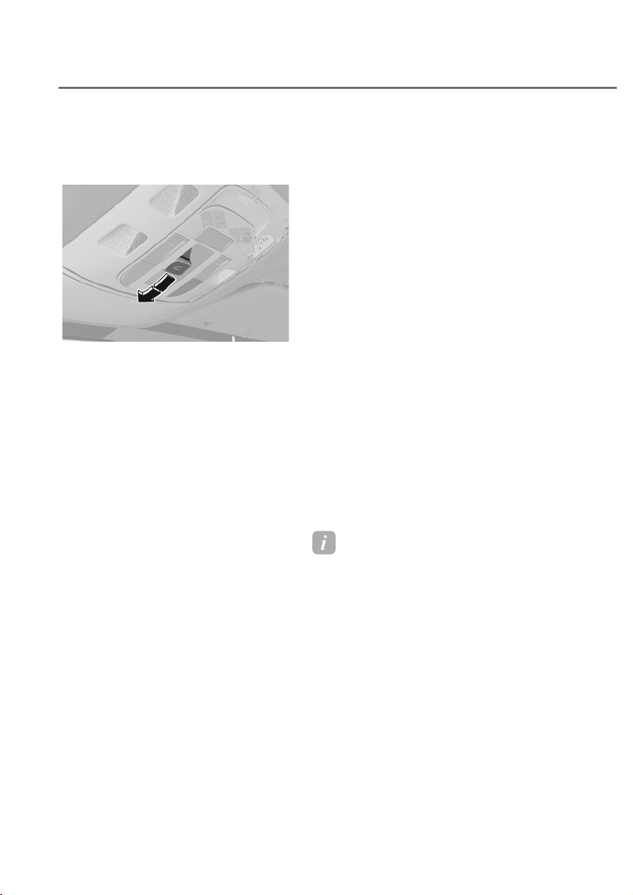
5-84
Convenience Features
Resetting the Sunroof
Front seat power sunshade and
glass
ORS052055N
ORS052055N
In some circumstances resetting the
sunroof operation may need to be
performed. Some instances where
resetting the sunroof may be required
include:
• When the 12-volt battery is either
disconnected or discharged
• When the sunroof fuse is replaced
• If the sunroof one-touch AUTO OPEN/
CLOSE operation is not functioning
properly
Sunroof resetting procedure:
1. It is recommended to perform the
reset procedure with the vehicle
engine running. Start the vehicle in P
(Park).
2. Make sure the power sunshade and
sunroof glass are in the fully closed
position. If the power sunshade
and sunroof glass are open, push
the switch forward until the power
sunshade and sunroof glass are fully
closed.
3. Release the switch when the power
sunshade and sunroof glass are fully
closed.
4. Push the switch forward until the
power sunshade and sunroof glass
move slightly. Then release the switch.
5. Once again push and hold the sunroof
switch forward until the power
sunshade and sunroof glass slide
open and close.
• Do not release the switch until the
operation is completed.
If you release the switch during
operation, start the procedure again
from step 2.
Information
If the sunroof is not reset when the vehicle
battery is disconnected or discharged, or
the sunroof fuse is blown, the sunroof may
not operate normally.
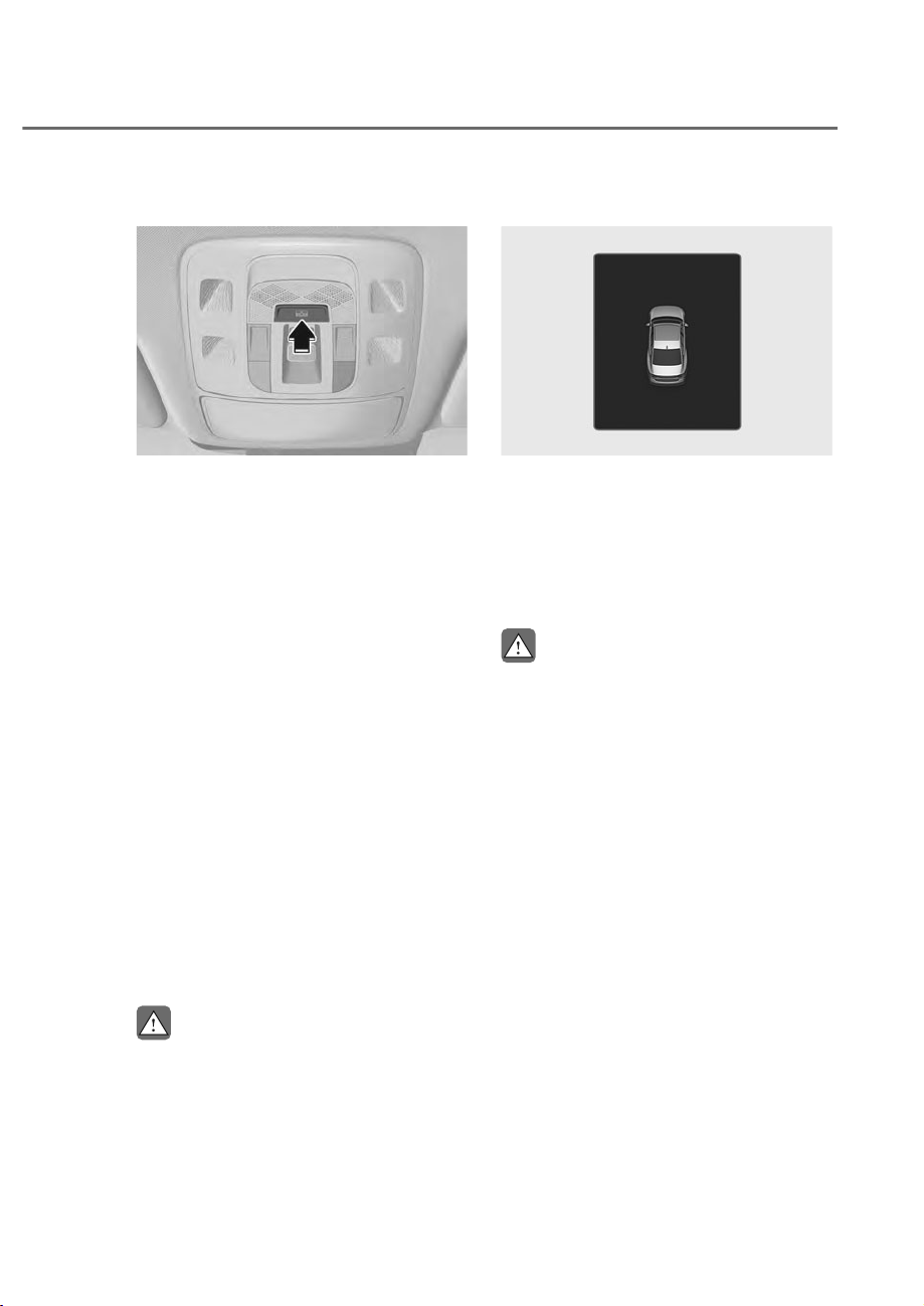
5-85
05
Rear Seat Power Sunshade
ORS052051N
ORS052051N
Reset the rear seat power sunshade in
the following situations.
• When the 12-volt battery is either
disconnected or discharged.
• When the rear seat power sunshade is
not working properly.
1. It is recommended to perform the
reset procedure with the vehicle
engine running. Start the vehicle in P
(Park).
2. Press and hold the switch until the
rear seat power sunshade is fully
closed.
3. Hold the switch until the rear seat
power sunshade slightly moves.
Release the switch until the sunshade
moves slightly.
4. Press and hold the switch again until
the power sunshade is opened then
closed.
• Do not release the switch until
the rear seat sunshade completes
opening/closing. If you release the
switch during operation, start the
procedure again from step 2.
CAUTION
The rear seat power sunshade may not
work properly if it is not reset.
Sunroof Open Warning
ORS041022
ORS041022
If the driver turns off the engine when
the sunroof is not fully closed, the
warning chime will sound for several
seconds and the sunroof open warning
will appear on the cluster LCD display.
Close the sunroof securely when leaving
your vehicle.
CAUTION
Make sure the sunroof is closed fully
when leaving your vehicle. If the
sunroof is left open, rain or snow may
wet the interior of the vehicle. Also,
leaving the sunroof open when the
vehicle is unattended may invite theft.
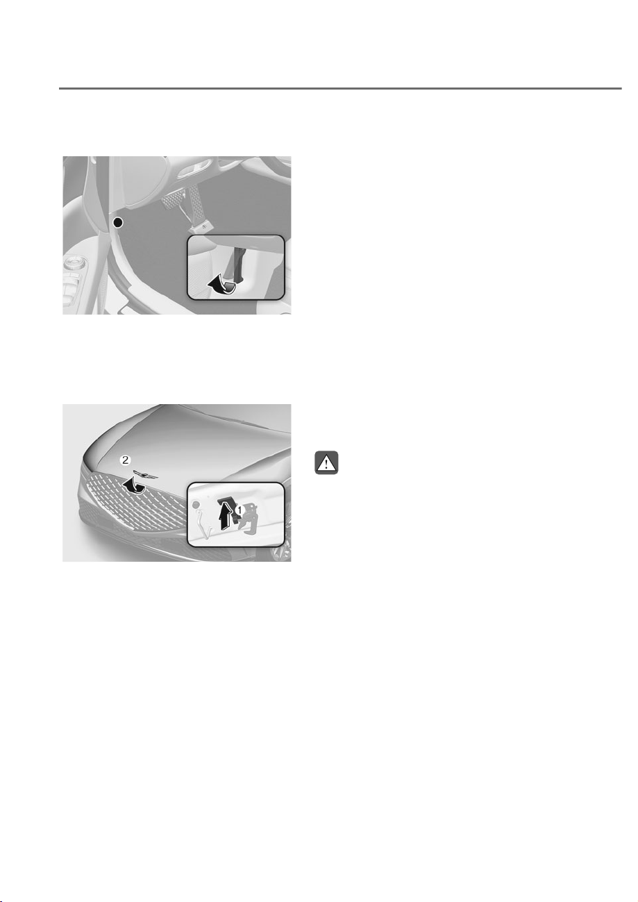
5-86
Convenience Features
Opening the Hood
ORS051056
ORS051056
1. Park the vehicle and set the parking
brake.
2. Pull the release lever to unlatch the
hood. The hood should pop open
slightly.
ORS051057
ORS051057
3. Go to the front of the vehicle, raise the
hood slightly, push up the secondary
hood release lever M inside of the
hood center and lift the hood N.
After the hood has been lifted halfway,
it will raise completely by itself.
Closing the Hood
1. Before closing the hood, check in and
around the engine compartment to
ensure the following:
- Any tools or other loose objects
are removed from the engine
compartment area or hood
opening area
- All glove, rags, or other
combustible material is removed
from the engine compartment
- All filler caps are tightly and
correctly installed
2. Lower the hood halfway (lifted
approximately 12 in. (30 cm) from the
closed position) and push down to
securely lock in place. Then double
check to be sure the hood is secure.
If the hood can be raised slightly, it is
not securely locked. Open it again and
close it with more force.
WARNING
• Before closing the hood, ensure
all obstructions are removed from
around the hood opening.
• Always double check to be sure that
the hood is firmly latched before
driving away. Check there is no
hood open warning light or message
displayed on the instrument cluster.
Driving with the hood opened may
cause a total loss of visibility, which
might result in an accident.
• Do not move the vehicle with the
hood in the raised position, as vision
is obstructed, which might result in
an accident, and the hood could fall
or be damaged.
HOOD

5-87
05
POWER TRUNK
Power Trunk Operating
Conditions
The power trunk operates when vehicle
speed is below 1.8 mph (3 km/h).
WARNING
• Never leave children or animals
unattended in your vehicle. Children
may operate the power trunk. Doing
so can result in injury to themselves
or others and can damage the
vehicle.
• Make sure there are no people or
objects and enough space around
the trunk before operating the
power trunk or smart trunk prior to
use. Serious injury, damage to the
vehicle or damage to surrounding
objects (for example, walls, ceilings,
vehicles, etc.) may result if contact
with the trunk occurs.
• Make sure there are no people or
objects around the trunk before
operating the power trunk. Wait
until the liftgate is opened fully and
stopped before loading or unloading
cargo from the vehicle.
• Always keep the trunk lid completely
closed while the vehicle is in motion.
If it is left open or ajar, poisonous
exhaust gases containing carbon
monoxide (CO) may enter the vehicle
and serious illness or death may
result.
NOTICE
• Do not close or open the power
trunk manually. This may cause
damage to the power trunk. If it is
necessary to close or open the power
trunk manually when the battery is
discharged or disconnected, do not
apply excessive force.
• Do not operate the power trunk more
than 10 times continuously when the
engine is not running. Use the power
trunk with the engine running when
the power trunk is used repeatedly to
prevent battery discharge.
• Do not leave the trunk open for a
long period of time. This may drain
the battery.
• Do not modify or repair any part of
the power trunk by yourself. Have the
system inspected by an authorized
retailer of Genesis Branded products.
• Do not operate the power trunk
under the following conditions.
The power trunk may not operate
properly.
- One side of the vehicle is lifted to
inspect the vehicle or change a tire
- Parking on an uneven road such as
a slope, etc.
• Close the trunk completely and lock
all doors and trunk using the central
door lock button before using an
automatic car wash.
• Do not spray high pressure water
directly on the power trunk outside
open/close button. The trunk may
open unintentionally.
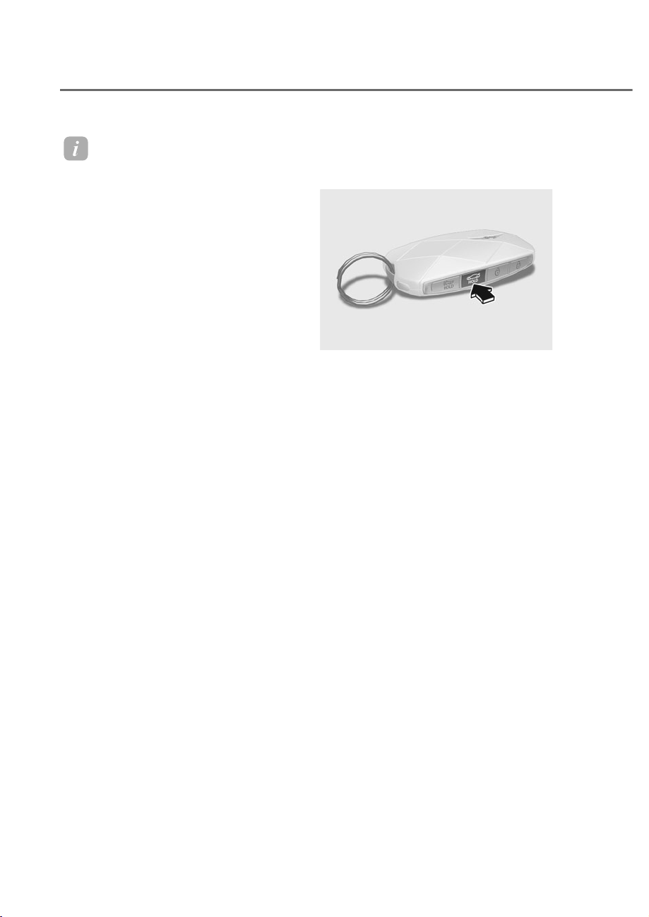
5-88
Convenience Features
Information
• In cold and wet climates, the outside
power trunk open button may not work
properly due to freezing conditions. If
this occurs, remove the ice before using
the outside power trunk open/close
button or use the power trunk open/
close button on the smart key or the
instrument panel.
• If you leave the smart key in the trunk
and close the trunk, a warning will
sound for about 5 seconds. If this
occurs, open the trunk by pressing the
power trunk open button on the outside
of the trunk.
• If there are obstacles such as snow
on the trunk, the trunk may not open
automatically. After removing the
obstacle, try to open it again.
• Be careful where there is an incline, as
the trunk lid may drop slightly when it
is stopped before it fully opens.
Operating the Power Trunk
Power trunk open button (Smart
key)
ORS051059
ORS051059
When the trunk is closed, press the
power trunk open button for 1 second.
The trunk will open with a warning
sound.
While the trunk is opening, press the
button to stop power trunk operation.
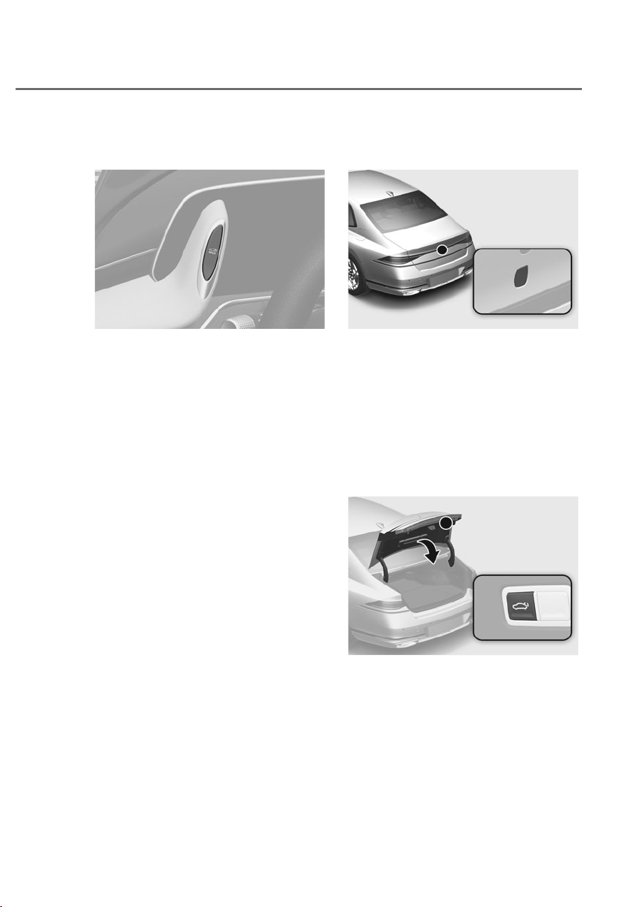
5-89
05
Power trunk open/close button
(Instrument panel)
ORS051060
ORS051060
When the trunk is closed, press the
power trunk open/close button for 1
second. The power trunk will open with a
warning sound.
While the trunk is opening, press the
button to stop power trunk operation.
When the trunk is opened, press and
hold the trunk open/close button to
close the power trunk. If you release the
button while the trunk is closing, power
trunk operation will stop.
Power trunk open button (Outside
the power trunk)
ORS051061L
ORS051061L
When the trunk is closed, press the
power trunk open button to open the
trunk.
If the vehicle is locked, press the power
trunk open button with the smart key in
your possession.
While the trunk is opening, press the
button to stop power trunk operation.
Power trunk close button (Inside the
power trunk)
ORS051062
ORS051062
Press the power trunk close button. The
trunk closes automatically.
While the trunk is closing, press the
button to stop power trunk operation.
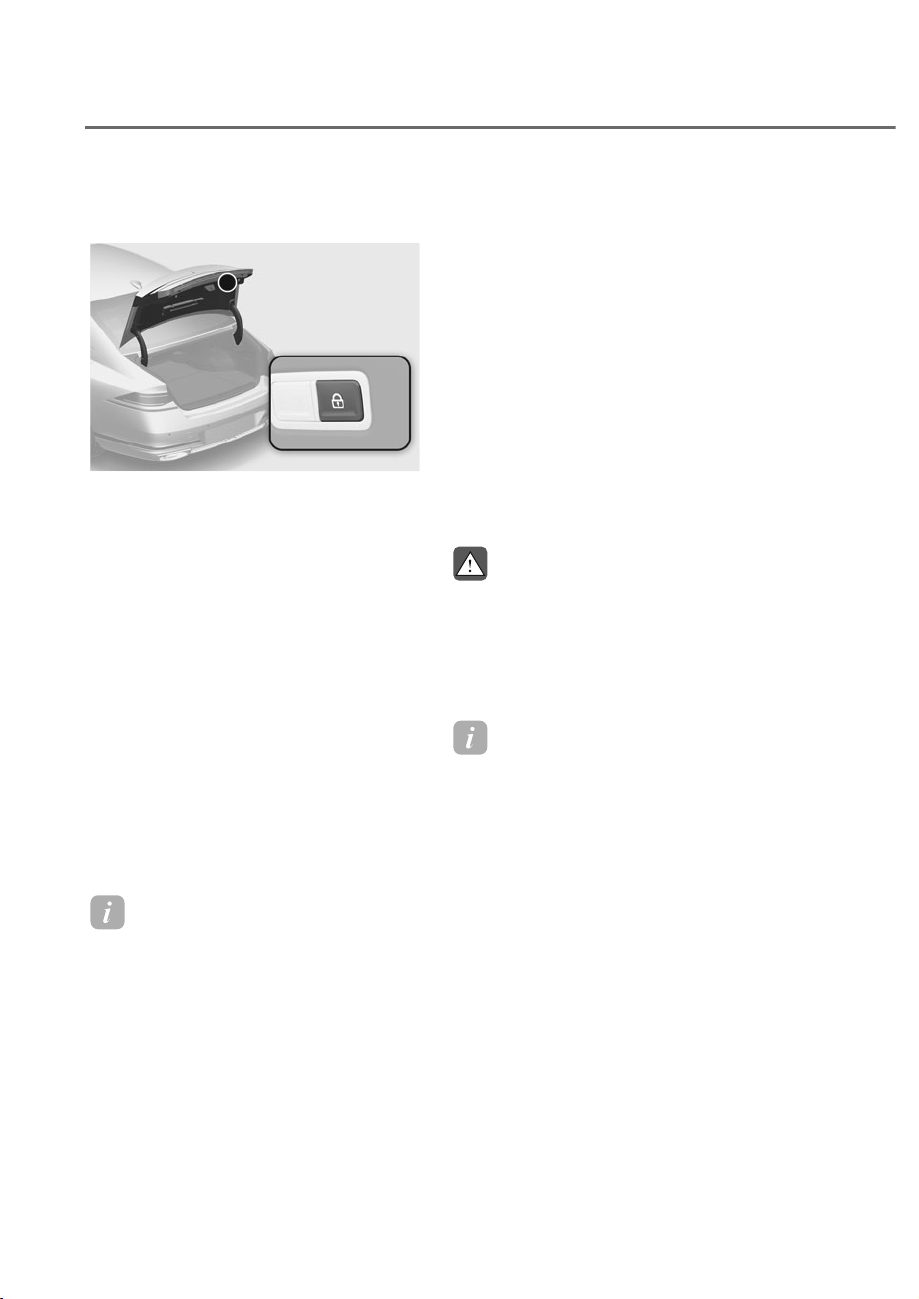
5-90
Convenience Features
Power trunk lock button (Inside the
power trunk)
ORS051063
ORS051063
Press the power trunk lock button while
carrying the smart key. The power trunk
closes and locks automatically.
Additionally, all doors will lock.
The trunk will close and lock, and all
doors will lock only when the engine is
off.
Switching the power trunk from
manual to automatic
If you apply over a certain amount
of power manually when the trunk is
opened, the power trunk system detects
the direction and closes or opens
automatically.
• The power trunk fully opens when the
trunk is raised
• The power trunk closes completely
when the trunk is lowered
Information
The power trunk may not operate
properly if the trunk is not opened above a
certain height.
Automatic reverse
During power trunk operation if the
power trunk senses any obstacle, the
trunk will stop or will fully open. The
automatic reverse feature may not
operate properly, or it may operate
unexpectedly under the following
circumstances:
• The automatic reverse feature may
not detect the resistance if the
detected resistance is below a certain
level, or if the trunk is almost fully
closed near the latched position.
• The automatic reverse feature may
operate if a strong impact is applied
with no obstructions placed.
WARNING
Never intentionally place any object
or part of your body in the path of the
power trunk to make sure the automatic
reverse feature operates. Serious injury,
or damage to the vehicle or object may
occur.
Information
The power trunk may stop operating if the
automatic reverse feature operates more
than two times while attempting to open
or close the trunk. If this occurs, carefully
open or close the trunk manually, and then
after 30 seconds try to operate the power
trunk automatically again.
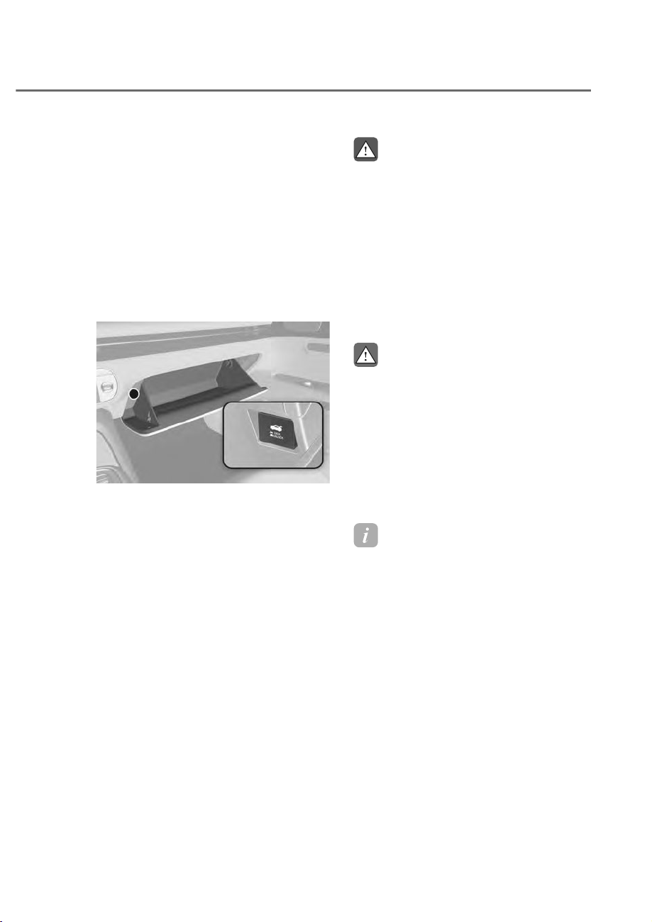
5-91
05
Power Trunk Settings
Power trunk opening height
To adjust the power trunk opening
KHLJKWVHOHFWȁ6HWXSɌ9HKLFOHɌ'RRU
7UXQNɌ3RZHU7UXQN2SHQLQJ+HLJKWȂLQ
the infotainment system.
The infotainment system may change
after updates. For detailed information
on system settings, see the infotainment
system web manual.
Trunk Lid Control Button
ORS051065
ORS051065
When the trunk lid control button is
in the UNLOCK (button not pressed)
position, the trunk can be controlled with
the power trunk open or close button.
When this trunk lid control button is in
the LOCK (button pressed) position, the
power trunk can be opened using the
trunk safety release lever.
The smart trunk does not operate, when
the trunk lid control button is pressed to
the LOCK position.
WARNING
Always be careful that all faces, hands,
arms, body parts are not in the path of
the power trunk. Even though the trunk
lid control button is in the LOCK (button
pressed) position, the trunk will still be
propelled upward by mechanical force
if the trunk is manually opened more
than 10 degrees beyond the fully closed
position. In addition, if the trunk is
manually closed to the secondary latch
position, the trunk will be electrically
moved to the fully latched position.
CAUTION
• Always keep the trunk lid control
button in the LOCK (button pressed)
position when not in use. Serious
injury or death can result from
unintentional operation.
• Do not leave valuables in the trunk.
Even though the trunk lid control
button is in the LOCK (button
pressed) position, the trunk can be
opened using the trunk release lever.
Information
&ORVHWKHWUXQNDQGNHHSWKHWUXQNOLG
FRQWUROEXWWRQLQWKH/2&.EXWWRQ
pressed) position before washing the
vehicle in an automatic car wash.
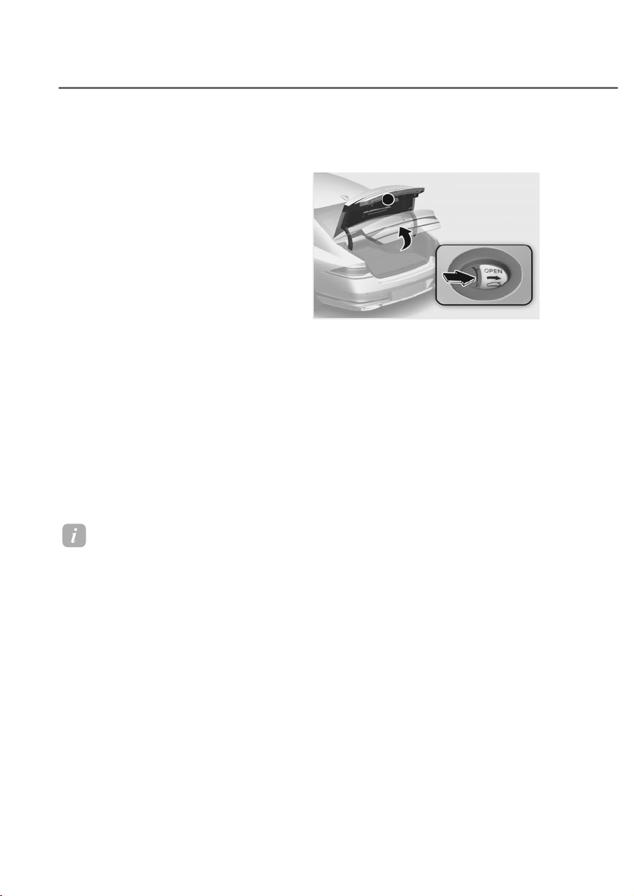
5-92
Convenience Features
Resetting the Power Trunk
In some circumstances resetting the
power trunk operation may need to
be performed. Some instances where
resetting the power trunk may be
required include:
• When the 12-volt battery is recharged
• When the 12-volt battery is reinstalled
after removal or replacement
• When the related fuse is reinstalled
after removal or replacement
1. With the engine off or running, put the
gear in P (Park).
2. While Pressing the power trunk close
inner button, press the power trunk
open outer button for more than 3
seconds. A chime will sound.
3. Slowly close the trunk manually.
4. Press the power trunk open outer
button. The trunk will open with a
chime sound.
Wait until the trunk fully opens to
complete resetting. If the trunk stops
before it is fully open, resetting cannot
be completed.
Information
If the power trunk does not operate
properly after the above procedure, have
the system inspected by an authorized
retailer of Genesis Branded products.
Emergency Trunk Safety Release
Inside the trunk
ORS051067
ORS051067
Your vehicle is equipped with an
emergency trunk safety release lever
located inside the trunk. When someone
is inadvertently locked in the trunk, the
trunk can be opened by moving the lever
in the direction of the arrow and pushing
the trunk lid to open.
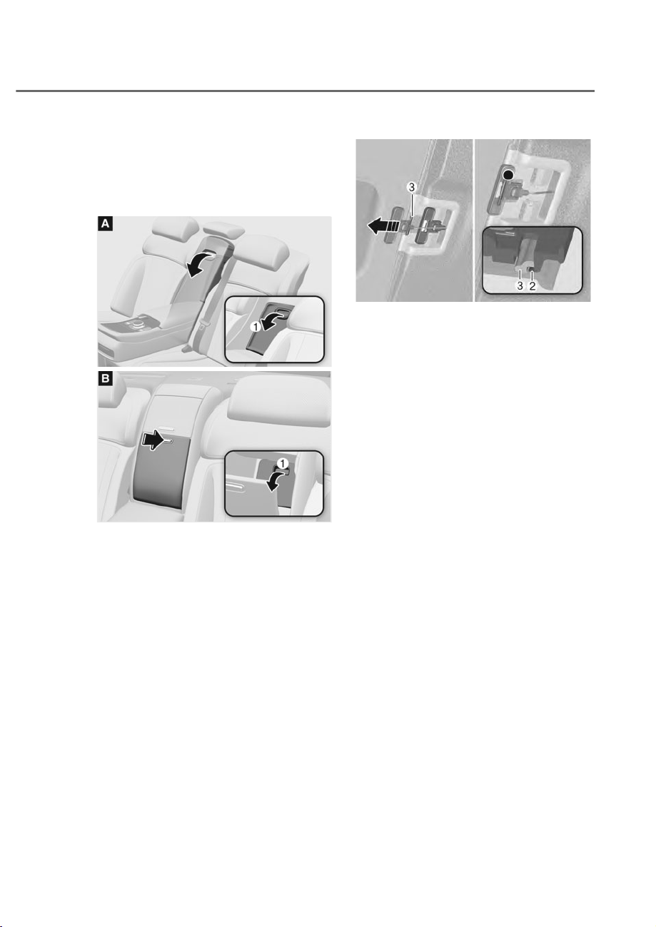
5-93
05
Inside the vehicle
Follow the below procedure to open
the trunk manually when the battery is
discharged or when there is a problem
with the vehicle:
ORS051068
ORS051068
ORS051277
ORS051277
1. Open the pass through cover M at the
center of the rear seat.
2. Pull trunk release lever all the way
back that is located behind the left
side of the pass through cover.
ORS051245-1
ORS051245-1
3. With the lever pulled to the end, fix
the lever O on the projecting part N.
4. Lift and open the trunk manually.
5. Place manual trunk release lever back
to original position or trunk will not
close.
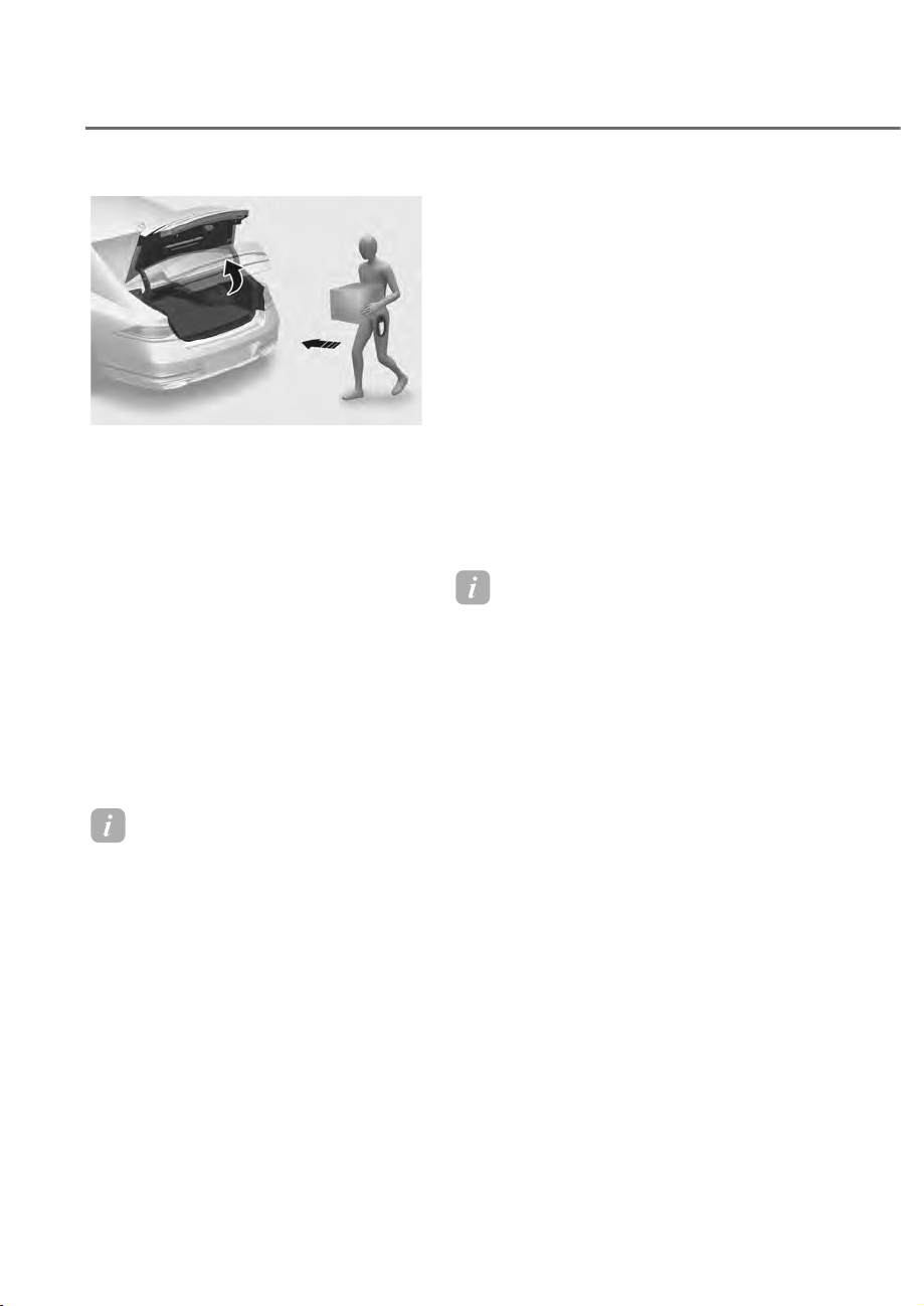
5-94
Convenience Features
60$577581.ʚ,)(48,33('ʛ
ORS051069
ORS051069
On a vehicle equipped with a smart key,
the trunk can be opened with hands-free
activation using the smart trunk system.
How to Use the Smart Trunk
The hands-free smart trunk system
can be opened automatically when the
following conditions are met:
• The smart trunk option is enabled in
the Settings menu in the infotainment
system screen.
• The smart trunk is activated and ready
15 seconds after all the doors are
closed and locked
• The smart trunk will open when the
smart key is detected in the area
behind the vehicle for 3 seconds
Information
7KHVPDUWWUXQNZLOO127RSHUDWHZKHQ
• Any door is open, or all doors are
closed but not locked
• The smart key is detected within 15
seconds from when the doors were
closed and locked
• For vehicles equipped with illuminated
exterior front door handles, if the smart
key is detected within 15 seconds from
when the doors were closed and locked
or if the smart key is within 60 in. (1.5
m) from the front door handles
• The smart key is in the vehicle.
1. Settings
To use smart trunk, it must be enabled
from the Settings menu in the
infotainment system screen. Select:
- 6HWXSɌ9HKLFOHɌ'RRU7UXQNɌ6PDUW
Trunk
See additional information in supplied
Infotainment Manual.
2. Detect and Alert
The smart trunk detecting area extends
approximately 20-40 in. (50-100 cm)
behind the vehicle. If you are positioned
in the detecting area and are carrying the
smart key, the hazard warning lights will
blink and the chime will sound to alert
you that the smart trunk will open.
Information
Do not approach the detecting area if you
do not want the trunk to open. If you have
unintentionally entered the detecting area
and the hazard warning lights and chime
starts to operate, move away from the area
behind the vehicle with the smart key. The
trunk will remain closed.
3. Automatic opening
After the hazard warning lights blink and
the chime sounds 6 times, the smart
trunk will open.
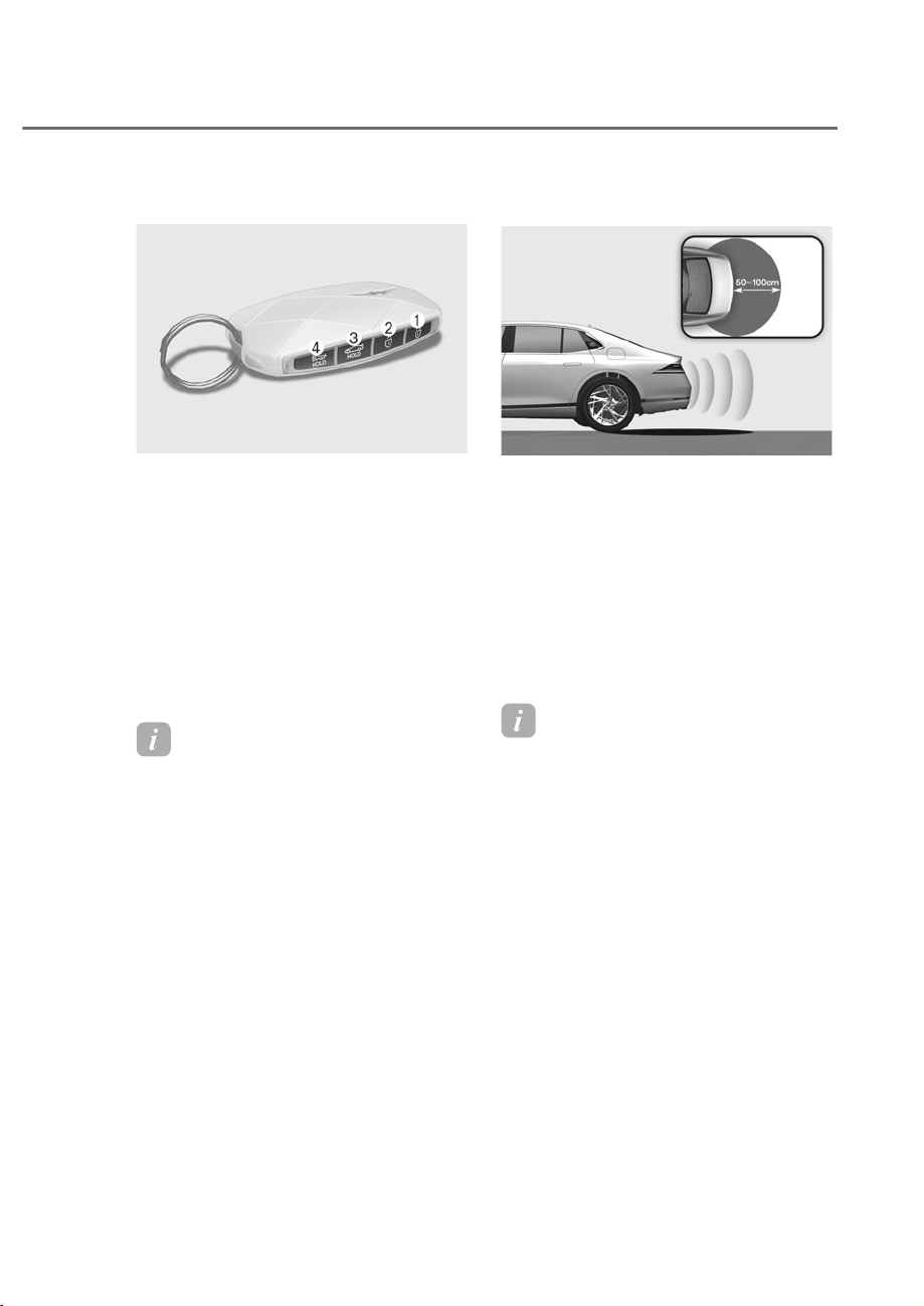
5-95
05
Deactivating smart trunk
ORS051070
ORS051070
M Door lock
N Door unlock
O Trunk open/close
P Panic
If you press any button on the smart key
during the Detect and Alert stage, the
smart trunk function will be deactivated.
Make sure to be aware of how to
deactivate the smart trunk function for
emergency situations.
Information
• If you press the door unlock button
N, the smart trunk function will be
deactivated temporarily. But, if you do
not open any door for 30 seconds, the
smart trunk function will be activated
again.
• If you press the trunk open button
O for more than 1 second, the trunk
opens.
• The smart trunk function will still be
activated if you press the door lock
button M or trunk open button O on
the smart key as long as the smart
trunk is not already in the Detect and
Alert stage.
• In case you have deactivated the smart
trunk function by pressing the smart
key button and opened a door, the
smart trunk function can be activated
again by closing and locking all doors.
Detecting Area
ORS051071L
ORS051071L
• The smart trunk detecting area
extends approximately 20-40 in. (50-
100 cm) behind the vehicle. If you are
positioned in the detecting area and
are carrying the smart key, the hazard
warning lights will blink and the chime
will sound for about 3 seconds to alert
you that the smart trunk will open.
• The alert stops once the smart key is
moved outside of the detecting area
within the 3 second period.
Information
• The smart trunk function may not
operate properly if any of the following
instances occur:
- The smart key is close to a radio
transmitter such as a radio station or
an airport which can interfere with
normal operation of the transmitter.
- The smart key is near a mobile two
way radio system or a cellular phone.
- Another vehicle’s smart key is being
operated close to your vehicle.
• The smart trunk detecting area may
change when:
- The vehicle is parked on an incline
- or slope.
- 2QHVLGHRIWKHYHKLFOHLVUDLVHGRU
lowered relative to the opposite side.
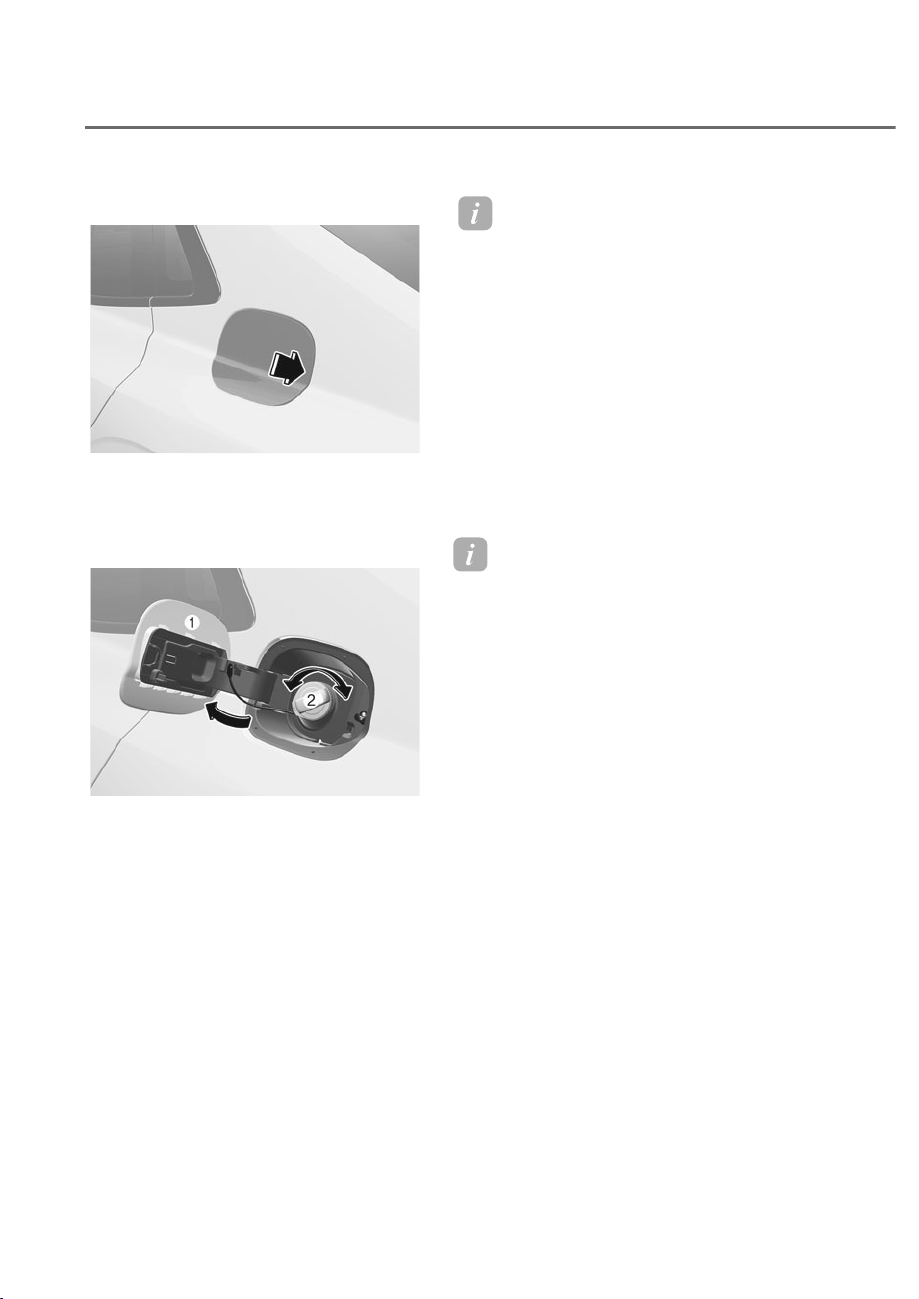
5-96
Convenience Features
2SHQLQJWKH)XHO)LOOHU'RRU
ORS051072
ORS051072
1. Turn the engine off.
2. Ensure the driver’s door is unlocked.
3. Push the fuel filler door near the 3
o’clock position.
ORS051073
ORS051073
4. Pull the fuel filler door M outward to
access the fuel tank cap.
5. To remove the fuel tank cap N, turn
it counterclockwise. You may hear a
hissing noise as the pressure inside
the tank equalizes.
6. Place the cap on the fuel filler door.
Information
If the fuel filler door does not open
because ice has formed around it, tap
lightly or push on the door to break the
ice and release the door. Do not pry on the
door. If necessary, spray around the door
with an approved deicer fluid (do not use
radiator antifreeze) or move the vehicle to
a warm place and allow the ice to melt.
&ORVLQJWKH)XHO)LOOHU'RRU
1. To install the fuel tank cap, turn it
clockwise until it “clicks” one time.
2. Close the fuel filler door until it is
latched securely.
Information
The fuel filler door will not close if the
driver’s door is locked. If you lock the
driver’s door while fueling, unlock it
before closing the fuel filler door.
)8(/),//(5'225

5-97
05
WARNING
Automotive fuel is highly flammable
DQGH[SORVLYH)DLOXUHWRIROORZWKHVH
guidelines may result in SERIOUS
INJURY or DEATH:
• Read and follow all warnings posted
at the gas station.
• Before refueling, note the location
RIWKH(PHUJHQF\)XHO6KXW2IILI
available, at the gas station.
• Before touching the fuel nozzle, you
should eliminate the potential build-
up of static electricity by touching
a metal part of the vehicle, a safe
distance away from the fuel filler
neck, nozzle, or other gas source,
with your bare hand.
• Do not use mobile phones while
refueling. Electric current and/or
electronic interference from cellular
phones can potentially ignite fuel
vapors and cause a fire.
• Do not get back into a vehicle
once you have begun refueling.
You can generate a buildup of
static electricity by touching,
rubbing or sliding against any item
or fabric capable of producing
static electricity. Static electricity
discharge can ignite fuel vapors
causing a fire. If you must re-enter
the vehicle, you should once again
eliminate potentially dangerous
static electricity discharge by
touching a metal part of the vehicle,
away from the fuel filler neck, nozzle
or other fuel source, with your bare
hand.
• When using an approved portable
fuel container, be sure to place the
container on the ground prior to
refueling. Static electricity discharge
from the container can ignite fuel
vapors causing a fire.
Once refueling has begun, contact
between your bare hand and the
vehicle should be maintained until
the filling is complete.
• Use only approved portable plastic
fuel containers designed to carry and
store fuel.
• When refueling, always shift the
gear to the P (Park) position, set
the parking brake, and press the
Engine Start/Stop button to the
2))SRVLWLRQ6SDUNVSURGXFHGE\
electrical components related to the
engine can ignite fuel vapors causing
a fire.
• Do not use matches or a lighter and
do not smoke or leave a lit cigarette
in your vehicle while at a gas station,
especially during refueling.
• Do not over-fill or top-off your
vehicle tank, which can cause fuel
spillage.
• If a fire breaks out during refueling,
leave the vicinity of the vehicle, and
immediately contact the manager
of the gas station and then contact
WKHORFDOILUHGHSDUWPHQW)ROORZDQ\
safety instructions they provide.
• If pressurized fuel sprays out, it can
cover your clothes or skin and thus
subject you to the risk of fire and
burns. Always remove the fuel cap
carefully and slowly. If the cap is
venting fuel or if you hear a hissing
sound, wait until the condition stops
before completely removing the cap.
• Always check that the fuel cap is
installed securely to prevent fuel
spillage in the event of an accident.

5-98
Convenience Features
Information
Make sure to refuel your vehicle according
to the “Fuel Requirements” section in
suggested in chapter 1.
NOTICE
• Do not spill fuel on the exterior
surfaces of the vehicle. Any type of
fuel spilled on painted surfaces may
damage the paint.
• If the fuel filler cap requires
replacement, use only a genuine
Genesis cap or the equivalent (of
the genuine part) specified for your
vehicle. An incorrect fuel filler cap
can result in a serious malfunction of
the fuel system or emission control
system.
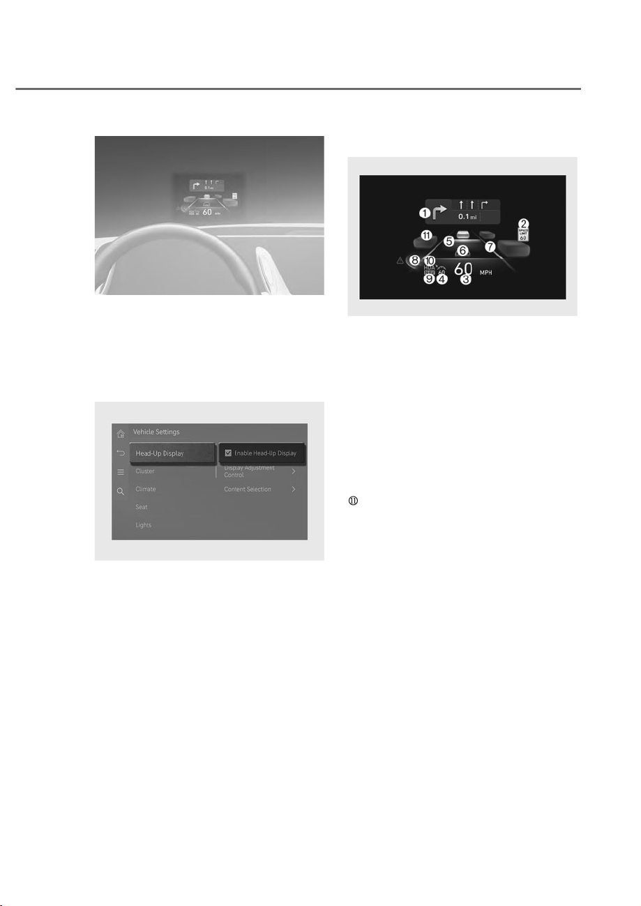
5-99
05
ORS052224N
ORS052224N
The Head-Up Display is an optional
feature that allows the driver to view
information projected onto a transparent
screen while still keeping your eyes
safely on the road ahead while driving.
Head-up Display Settings
ORS051237L
ORS051237L
• Head-up display can be enabled from
the Settings menu in the infotainment
system screen. Select:
- 6HWXSɌ9HKLFOHɌ+HDG8S'LVSOD\
Ɍ(QDEOH+HDG8S'LVSOD\
• After turning on the head-up
display, you can change the settings
of ‘Display Control’ and ‘Content
Selection’ of the head-up display.
The infotainment system may
change after updates. See additional
information in supplied Infotainment
Manual .
Head-up Display Information
ORG3051266N
ORG3051266N
M Turn by Turn (TBT) navigation
N Traffic signs or speed limit
O Speedometer
P SCC set speed
Q SCC vehicle distance
R Lane Following Assist
S Lane Safety
T Blind-Spot Safety
U Highway Auto Speed Change
V Highway Driving Assist
Surrounding vehicles(if equipped)
+($'ʏ83',63/$<ʚ+8'ʛʚ,)(48,33('ʛ

5-100
Convenience Features
Precautions While Using the
Head-up Display
• It may sometimes be difficult to read
information on the head-up display in
the following situations.
- The driver is improperly positioned
in the driver’s seat.
- The driver wears polarizing-filter
sunglasses.
- An object is located above the
head-up display cover
- The vehicle is driven on a wet road.
- Any improper lighting accessory is
installed inside the vehicle, or there
is incoming light from outside of the
vehicle.
- The driver wears glasses.
- The driver wears contact lenses.
When it is difficult to read the head up
display information, adjust the image
height or brightness level from the
Settings menu in the infotainment
system screen.
• For your safety, make sure to stop the
vehicle before adjusting the settings.
• Do not tint the front windshield glass
or add other types of metallic coating.
Otherwise, the head-up display image
may be invisible.
• Do not place any accessories on the
crash pad or attach any objects on the
windshield glass.
• When replacing the front windshield
glass, replace it with a windshield
glass designed for head-up display
operation. Otherwise, duplicated
images may be displayed on the
windshield glass.
WARNING
The warning information of Blind-Spot
Safety on the head-up display are
supplemental. Do not solely depend on
them to change lanes. Always take a
look around before changing lanes.
Information
Head-up Display includes GPL, LGPL,
MPL and other open source license
softwares. All license notices including
related source code are provided at http://
www.mobis.co.kr/opensource/list.do.
If the driver requests on-board
VRIWZDUHRSHQVRXUFHFRGHYLD02%,6B
266UHTXHVW#PRELVFRNUZLWKLQ\HDUV
DIWHUEX\LQJWKLVSURGXFWD&'520RU
other storage device will be sent with the
minimum cost covering storage device cost
and delivery cost.
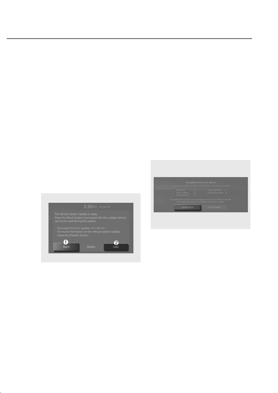
5-101
05
The Over-The-Air software update
feature allows you to wirelessly update
software to the latest version. Using
this feature, you can keep your vehicle
system up to date with the latest
software without visiting an authorized
retailer of Genesis Branded products.
• Over-The-Air software update is an
option, visiting your selected dealer
will continue to be an option.
Downloading Software
Vehicles with Active and Enrolled
Genesis Connected Services can
automatically download software while
driving. After the latest software has
been successfully downloaded, you will
receive a notification on your phone or
on the vehicle screen that the software
update is available and ready to install.
Approving Software Update
ORS052313N
ORS052313N
After the vehicle ignition is turned off,
the vehicle system will provide the
option to start the update.
• To start the update, press ‘Start’ M.
• To postpone the update, press ‘Later’
N.
Preparing Software Update
If you press the ‘Start’ button on the
screen, the vehicle will begin installing
the update automatically. The following
conditions must be satisfied:
• The vehicle must be off.
• The gear must be in P (Park).
• The Electronic Parking Brake (EPB)
must be applied.
• The exterior lights must be turned off.
• The hood must be closed.
• The battery must be sufficient.
• The systems to be updated must not
be running.
ORS051239L
ORS051239L
• To update immediately, press ‘Update
Now’.
• To cancel the update, press ‘Cancel
Update’.
29(5ʏ7+(ʏ$,562)7:$5(83'$7(

5-102
Convenience Features
Updating Software
ORS052314N
ORS052314N
You can see the progress of the update
on the screen.
After the update is complete, you will
receive a notification on your phone
or the vehicle screen that the software
update is complete.
Information
The screen turns off automatically after 3
minutes to save the battery. If the screen
turns off automatically, you can check the
update progress by pressing the Engine
Start/Stop button.
Information
• After the update starts, you can exit the
vehicle.
• 7KH2YHU7KH$LUVRIWZDUHXSGDWH
feature is only available for Active and
(QUROOHG*HQHVLV&RQQHFWHG6HUYLFHV
users.
• The update details may vary, for details
you can visit the What’s New link.
• &KHFNWKHQRWLFHIRUWKH2YHU7KH$LU
software update on mygenesis.com
• ,IWKHXSGDWHIDLOVWKH(&8ZLOO
attempt to recovery itself automatically
(rollback). If you want to retry the
software update, even after a successful
UHFRYHU\FRQWDFW*HQHVLV&XVWRPHU
&DUH
• If the update or recovery fails, contact
*HQHVLV&XVWRPHU&DUH
• After the update is complete, it
may provide new functions or
improvements. For more information,
VHHWKH³2YHU7KH$LUVRIWZDUH
update” page on mygenesis.com

5-103
05
NOTICE
• Observe the following restrictions
during the update.
- You cannot use the vehicle during
the update. Be sure to have
enough time for the update, and
safely park the vehicle before
starting the update process.
- You cannot use remote features,
including remote start.
- The Rear Occupant Alert feature
may not work. Check if there are
any occupants in the rear seat.
- If there is an update for the Genesis
Digital Key feature, the doors
cannot be locked or unlocked
using the digital key, or fingerprint
recognition. If the Genesis Digital
Key feature is being updated, use
the smart key to lock or unlock the
doors.
• The update will be automatically
canceled if any vehicle conditions
required for the update are changed
before starting the update.
• Once the update has started, you
cannot cancel the update.
• You cannot use the Over-The-Air
software update feature if you
modify or replace any vehicle
software.
• Do not open the hood or replace
the battery in the vehicle during the
update. The update may fail.
• If a diagnostic tool of any kind is
connected to the vehicle OBD (On-
board Diagnostic) terminal, the
vehicle cannot be updated. The
vehicle can be updated by removing
the diagnostic tool connected to the
OBD terminal and then restarting the
vehicle.
• If the update is not completed
successfully, contact Genesis
Customer Care.
• Vehicle reception must be identified
as Verizon to safely install any
downloaded software.
• Vehicle signal strength, must be
strong (above -82 dbm) to safely
install any downloaded software.
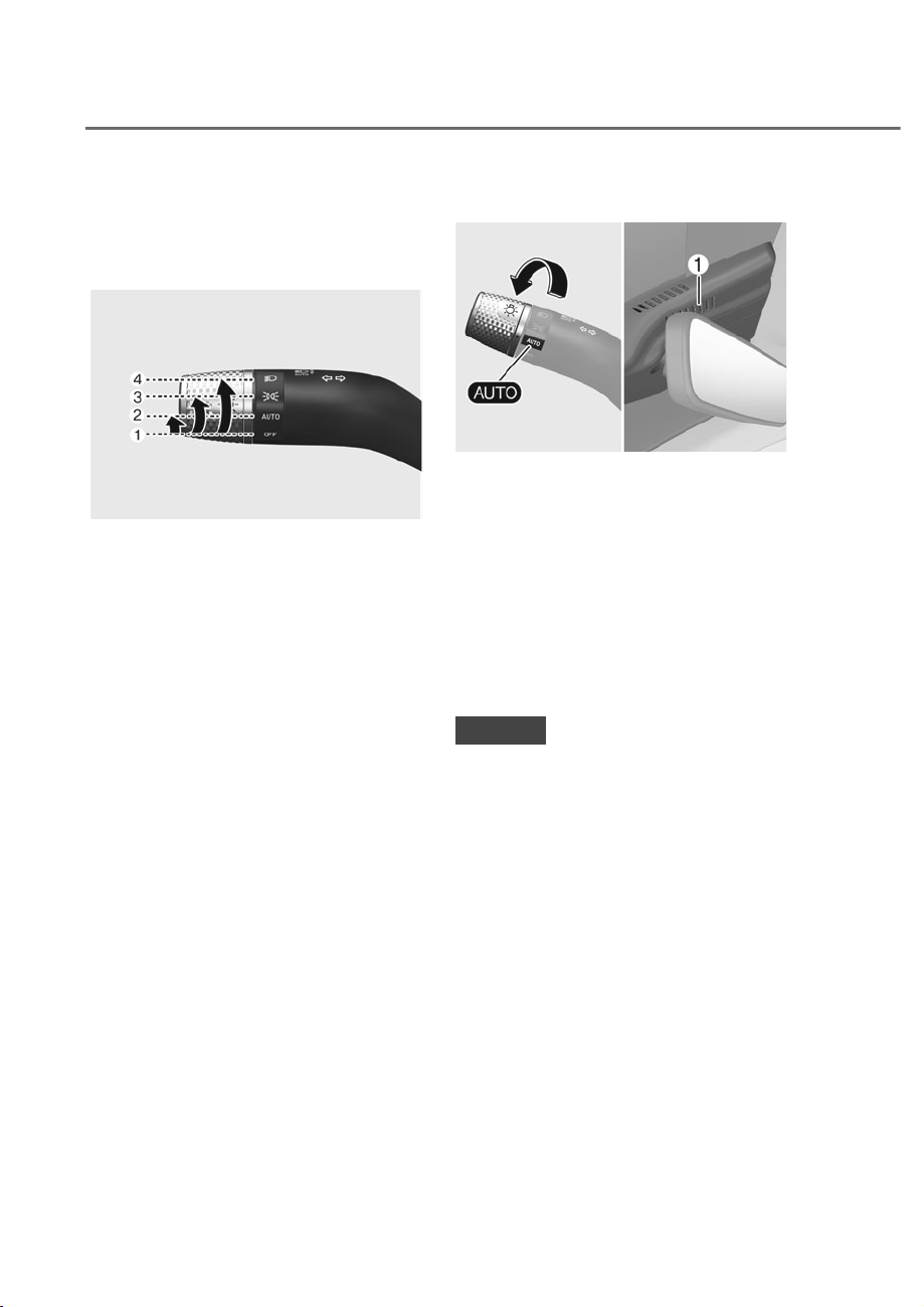
5-104
Convenience Features
EXTERIOR LIGHTS
Lighting Control
To operate the lights, turn the knob at
the end of the control lever to one of the
following positions:
OJX1059057
OJX1059057
M OFF
N AUTO headlight
O Parking lamp
P Headlight
Daytime Running Light (DRL)
The Daytime Running Lights (DRL) can
make it easier for others to see the front
of your vehicle during the day, especially
after dawn and before sunset.
The DRL system will turn the dedicated
lamp OFF when:
• The headlights are ON.
• The parking brake is applied.
• The vehicle is turned off.
$872KHDGOLJKW
ORS051076
ORS051076
The parking lamp and headlight will
be turned ON or OFF automatically
depending on the amount of daylight as
measured by the ambient light sensor M
at the upper end of the windshield glass.
Even with the AUTO headlight feature
in operation, it is recommended to
manually turn ON the headlights when
driving at night or in a fog, driving in the
rain, or when you enter dark areas, such
as tunnels and parking facilities.
NOTICE
• Do not cover or spill anything on the
sensor M located at the upper end of
the windshield glass.
• Do not clean the sensor using
a window cleaner, the cleanser
may leave a light film which could
interfere with sensor operation.
• If your vehicle has window tint or
other types of metallic coating on the
front windshield, the AUTO headlight
system may not work properly.
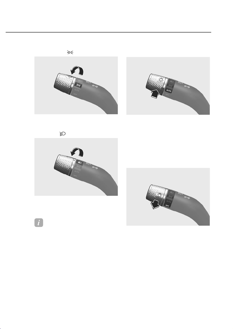
5-105
05
Parking lamp (
(
)
ORS051269
ORS051269
The parking lamp, license plate lamp and
instrument panel lamp are turned ON.
Headlight (
(
)
ORS051270
ORS051270
The headlight, parking lamp, license
plate lamp and instrument panel lamp
are turned ON.
Information
The Engine Start/Stop button must be in
WKH21SRVLWLRQWRWXUQRQWKHKHDGOLJKW
High Beam Operation
ORS051271L
ORS051271L
To turn on the high beam headlight, push
the lever away from you. The lever will
return to its original position.
The high beam indicator will light when
the headlight high beams are switched
on.
To turn off the high beam headlight, pull
the lever towards you. The low beams
will turn on.
ORS051273L
ORS051273L
To flash the high beam headlight, pull the
lever towards you, then release the lever.
The high beams will remain ON as long
as you hold the lever towards you.
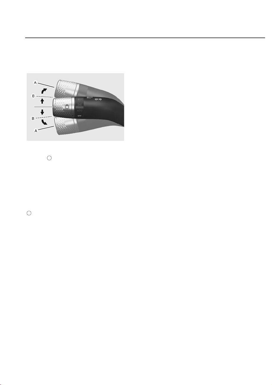
5-106
Convenience Features
Turn Signals and Lane Change
Signals
ORG3EV051074
ORG3EV051074
To signal a turn, push down on the lever
for a left turn or up for a right turn in
position
A
.
If an indicator stays on and does not flash
or if it flashes abnormally, one of the turn
signal bulbs may be burned out and will
require replacement.
2QHWRXFKWXUQVLJQDO
To use One Touch Turn Signal push the
turn signal lever up or down to position
B
and then release it.
The lane change signals will blink 3, 5 or
7 times.
You can enable the One Touch Turn
Signal function or choose the number
RIEOLQNLQJE\VHOHFWLQJȁ6HWXSɌ9HKLFOH
Ɍ/LJKWVɌ2QH7RXFK7XUQ6LJQDOɌȺ
flashes/5 flashes /7 flashes/Off’ in the
infotainment system screen.
See additional information in supplied
Infotainment Manual.
%DWWHU\6DYHU)XQFWLRQ
The purpose of this feature is to prevent
the battery from being discharged.
The system automatically turns off the
parking lamp when the driver turns the
vehicle off and opens the driver-side
door.
With this feature, the parking lamps will
turn off automatically if the driver parks
on the side of road at night.
However, the parking lamps stay ON
even when the driver-side door is opened
if the headlight switch is turned to the
parking lamp or AUTO (if equipped)
position after the engine is turned off.
If necessary, to keep the lamps on
turn the parking lamps OFF and ON
again using the headlight switch on
the steering column after the engine is
turned off.

5-107
05
+HDGOLJKW'HOD\)XQFWLRQ
If the Engine Start/Stop button is in the
ACC position or the OFF position with
the headlights ON, the headlights (and/
or parking lamps) remain on for about
5 minutes. However, if the driver’s door
is opened and closed, the headlights
are turned off after 15 seconds. Also,
with the vehicle off if the driver’s door is
opened and closed, the headlights (and/
or parking lamps) are turned off after 15
seconds.
The headlights (and/or parking lamps)
can be turned off by pressing the lock
button on the smart key twice or turning
the headlight switch to the OFF or AUTO
position.
You can enable the headlight delay
IXQFWLRQE\VHOHFWLQJȁ6HWXSɌ9HKLFOH
Ɍ/LJKWVɌ+HDGOLJKW'HOD\ȂLQWKH
infotainment system screen.
See additional information in supplied
Infotainment Manual.
NOTICE
If the driver exits the vehicle through
another door besides the driver
door, the battery saver function
does not operate and the headlight
GHOD\IXQFWLRQGRHVQRWWXUQ2))
automatically.
This may cause the battery to
discharge. To avoid battery discharge,
WXUQ2))WKHKHDGOLJKWVPDQXDOO\IURP
the headlight switch before exiting the
vehicle.
WARNING
If the function does not work properly,
have the system inspected by an
authorized retailer of Genesis Branded
products. Do not attempt to inspect or
replace the wiring yourself.
Headlight Moisture Removal
)XQFWLRQ
When moisture fogs up inside of the
headlight, if the headlights are on for
certain period of time, the fan circulates
the air inside to remove moisture. If
moisture is not removed, have the
vehicle inspected by an authorized
retailer of Genesis Branded products.
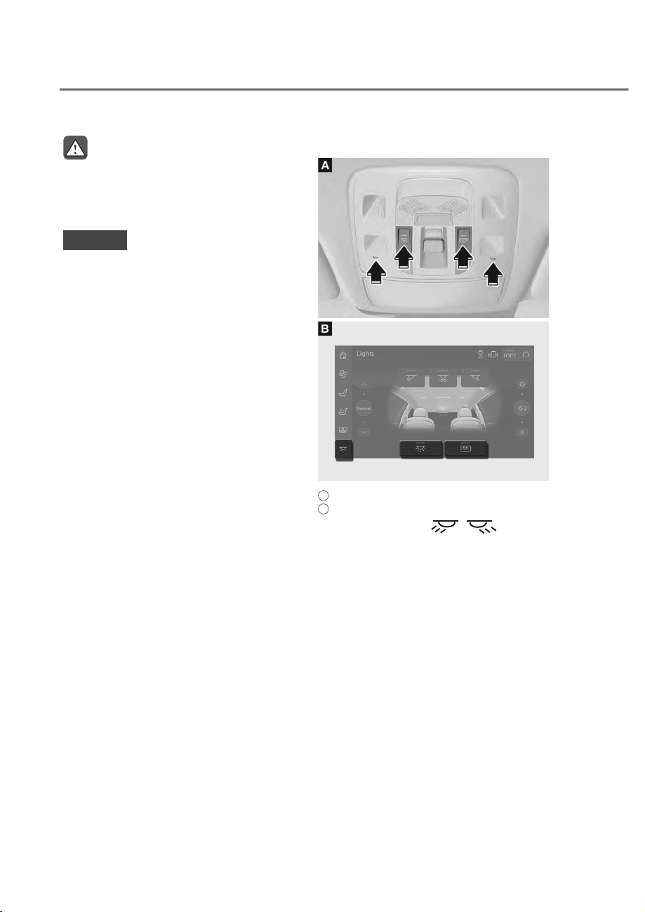
5-108
Convenience Features
INTERIOR LIGHTS
WARNING
Do not use the interior lights when
driving in the dark. The interior lights
may obscure your view and cause an
accident.
NOTICE
Do not use the interior lights for
extended periods when the vehicle is
turned off or the battery will discharge.
Interior Lamp AUTO Cut
The interior lamps will automatically go
off approximately 20 minutes after the
vehicle is turned off and the doors are
closed. If a door is opened, the lamp
will go off 25 minutes after the vehicle
is turned off. If the doors are locked by
the smart key and the vehicle enters the
armed stage of the theft alarm system,
the lamps will go off five seconds later.
)URQW/DPSV
ORS052078N
ORS052078N
ORS051250L
ORS051250L
A
: Front overhead console
B
: Rear seat armrest touchscreen
• Front map lamp ( ):
Touch either icons to turn the map
lamp on or off. This light produces a
spot beam for convenient use as a
map lamp at night or as a personal
lamp for the driver and the front
passenger.
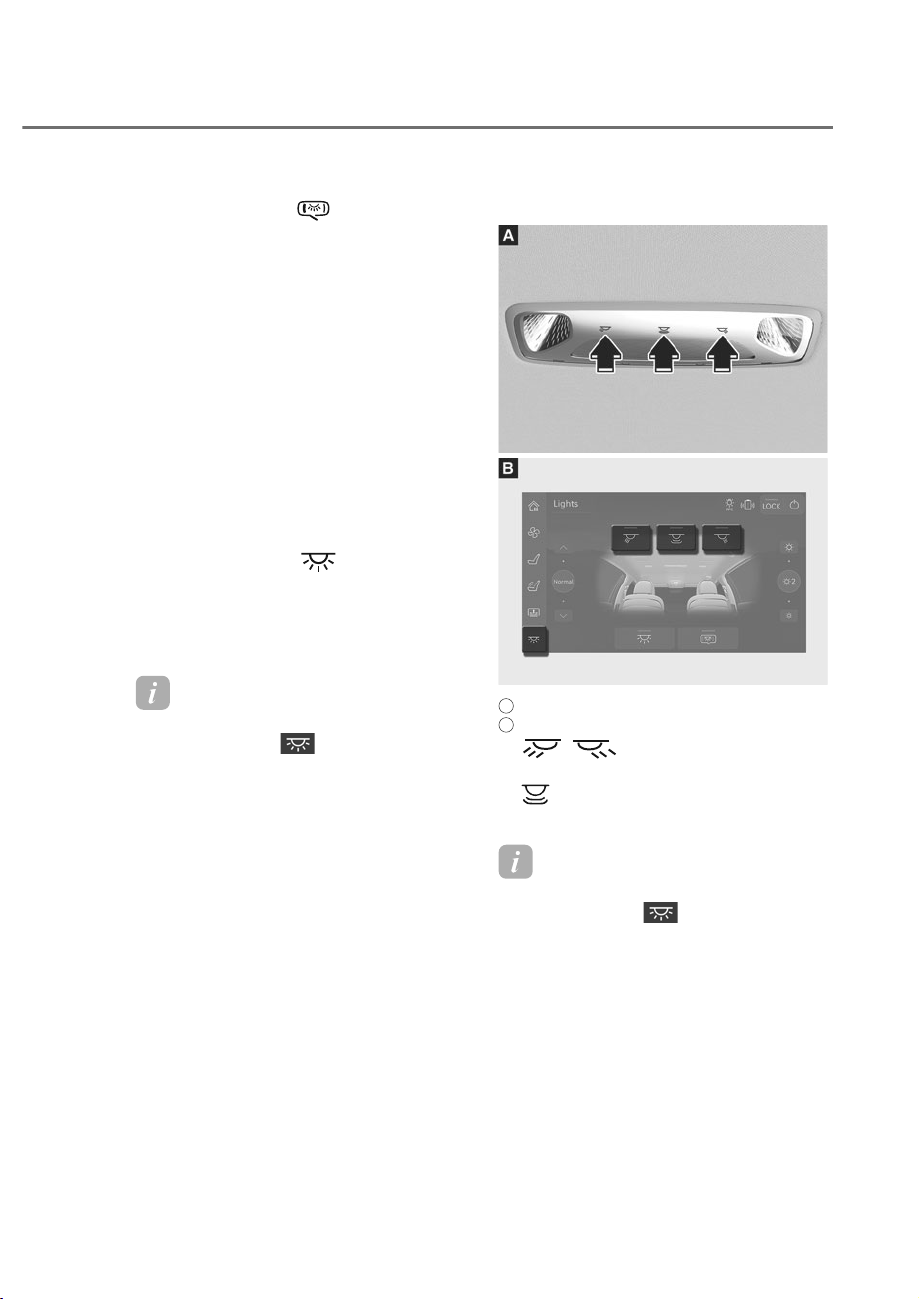
5-109
05
• Front door lamp ( ):
The front or rear room lamps come
on when the front or rear doors are
opened. When doors are unlocked
by the smart key, the front and rear
lamps come on for approximately
30 seconds as long as any door
is not opened. The front and rear
room lamps go out gradually after
approximately 30 seconds when the
door is closed. However, if the Engine
Start/Stop button is in the ON position
or all doors are locked, the front and
rear lamps will turn off. If a door is
opened with the Engine Start/Stop
button in the ACC position or the OFF
position, the front and rear lamps will
stay on for about 5 minutes.
• Front room lamp (
)
Press the button to turn on the room
lamp for the front and rear seats.
Press the button again to turn off all
the lamps.
Information
7RDGMXVWWKHOLJKWVXVLQJWKHUHDUDUPUHVW
touchscreen, press
from the left side
menu on the touchscreen.
Rear Lamps
ORS051079
ORS051079
ORS051251L
ORS051251L
A
: Rear seat (if equipped)
B
: Rear seat armrest touchscreen (if equipped)
• : Touch the icon to turn
either lamp on or off.
•
: Touch the icon to turn the lamp
on or off.
Information
7RDGMXVWWKHOLJKWVXVLQJWKHUHDUDUPUHVW
touchscreen, press
from the left side
menu on the touchscreen.
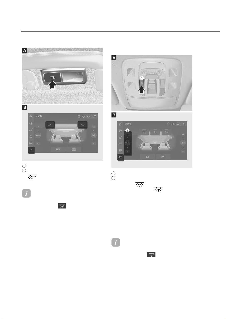
5-110
Convenience Features
ORS051080
ORS051080
ORS051252L
ORS051252L
A
: Rear seat (if equipped)
B
: Rear seat armrest touchscreen
• : Press the button to turn the
lamp on or off.
Information
7RDGMXVWWKHOLJKWVXVLQJWKHUHDUDUPUHVW
touchscreen, press
from the left side
menu on the touchscreen.
Interior Lamp Color Temperature
ORS052253N
ORS052253N
ORS051255L
ORS051255L
A
: Front overhead console
B
: Rear armrest touchscreen
M Press the button to turn all the
lamps on. Hold the
button for
over 1 second to change the color
temperature as follows.
- :DUPɌ1RUPDOɌ&RRO
N
From the lighting menu of the rear
armrest touchscreen, slide the left
sidebar or touch the arrows to change
the color temperature as follows.
- :DUPɌ1RUPDOɌ&RRO
Information
7RDGMXVWWKHOLJKWVXVLQJWKHUHDUDUPUHVW
touchscreen, press
from the left side
menu on the touchscreen.
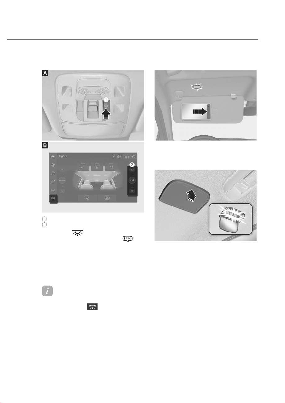
5-111
05
Interior Lamp Brightness
ORS052254N
ORS052254N
ORS051256L
ORS051256L
A
: Front overhead console
B
: Rear armrest touchscreen
M Press the button and turn on all
the lamps. Press and hold the
button for over 1 second to change the
brightness.
N
From the lighting menu of the rear
armrest touchscreen, slide the right
sidebar or touch the arrows to change
the brightness in 3 stages.
Information
7RDGMXVWWKHOLJKWVXVLQJWKHUHDUDUPUHVW
touchscreen, press
from the left side
menu on the touchscreen.
Vanity Mirror Lamp
ORS051274
ORS051274
Opening the lid of the vanity mirror will
automatically turn on the mirror lamp.
Rear Mirror Lamp (if equipped)
ORS051081
ORS051081
Press the cover and it will slowly open
and the mirror lamp will turn on.
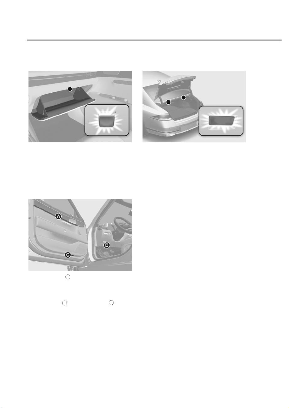
5-112
Convenience Features
Glove Box Lamp
ORS051082
ORS051082
The glove box lamp turns on when the
glove box is opened.
If the glove box is not completely closed,
the lamp will stay on for about 20
minutes.
0RRG/DPS)RRW/DPS'RRU
)RRW/DPS
ORS091052
ORS091052
• Mood lamp
A
: The lamp turns on
ZKHQȁ6HWXSɌ9HKLFOHɌ/LJKWVɌ
Ambient Light’ is selected from the
infotainment system screen.
• Foot lamp
B
, Door foot lamp
C
: The
lamp turns on when a door is opened
and turns off when the door is closed.
Trunk Lamp
ORS051083
ORS051083
The trunk lamp comes on when the trunk
is opened.
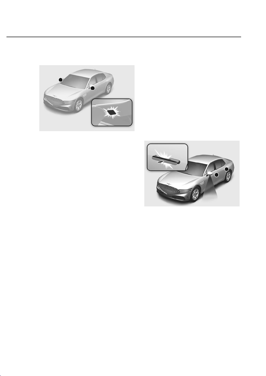
5-113
05
Puddle Lamp
ORS051084L
ORS051084L
Welcome light
When all doors (and trunk) are closed
and locked, the puddle lamp will turn
on for 15 seconds if any of the below is
performed.
• The doors are unlocked by the smart
key.
• The outside door handle touch sensor
is touched with the smart key in
possession.
• The vehicle is approached with the
smart key in possession. (if equipped)
The puddle lamp turns off if the Engine
Start/Stop button is in the ACC position
with a door open.
For more details, refer to “Welcome
System” in this chapter.
Escort light
When the Engine Start/Stop button is in
the OFF position and the driver’s door is
opened, the puddle lamp will turn on for
30 seconds. If the driver’s door is closed
within the 30 second period, the puddle
lamp will turn off after 15 seconds. If the
driver’s door is closed and locked, the
puddle lamp will turn off immediately.
The Puddle Lamp Escort Light will turn
on only the first time the driver’s door is
opened after the engine is turned off.
Welcome System
ORS051077L
ORS051077L
Welcome system helps keep the driver
visible by turning on vehicle lights when
the driver approaches the vehicle.

5-114
Convenience Features
Puddle lamp and door handle lamp
:LWK6HWXSɌ9HKLFOHɌ:HOFRPH0LUURU
/LJKWɌ2QGRRUXQORFNVHOHFWHGIURP
the Settings menu in the infotainment
system screen, and all the doors (and
trunk) are closed and locked, the puddle
lamp and door handle lamp will turn on
for approximately 15 seconds if any of the
below is performed.
- The door unlock button is pressed on
the smart key.
- The outside door handle touch sensor
is touched with the smart key in
possession.
- The vehicle is approach with the
smart key in possession when ‘Setup
Ɍ9HKLFOHɌ&RQYHQLHQFHɌ:HOFRPH
0LUURU/LJKWɌ2Q'ULYHU$SSURDFKȂLV
selected from the Settings menu in
the infotainment system screen.
See additional information in supplied
Infotainment Manual.
Dynamic welcome light
(if equipped)
When all doors (and trunk) are closed
and locked, the dynamic welcome light
will turn on for 15 seconds if the door
unlock button is pressed on the smart
key.
Information
The dynamic welcome light turns on at
QLJKWZKHQWKHOLJKWVZLWFKLVLQWKH$872
headlight position,
The dynamic welcome light operates for
about 2 seconds, and at the same time
the parking lights turn on for about 15
seconds.
At this time, if you press the door lock
or door unlock button on the smart key,
the dynamic welcome light turns off
immediately.
Interior lamp
When the interior lamp switch is in the
position and all doors (and trunk)
are closed and locked, the room lamp
will come on for 30 seconds if any of the
below is performed.
- The door unlock button is pressed on
the smart key.
- The outside door handle touch sensor
is touched with the smart key in
possession.
At this time, if you press the door lock
or unlock button on the smart key, the
lamps will turn off immediately.
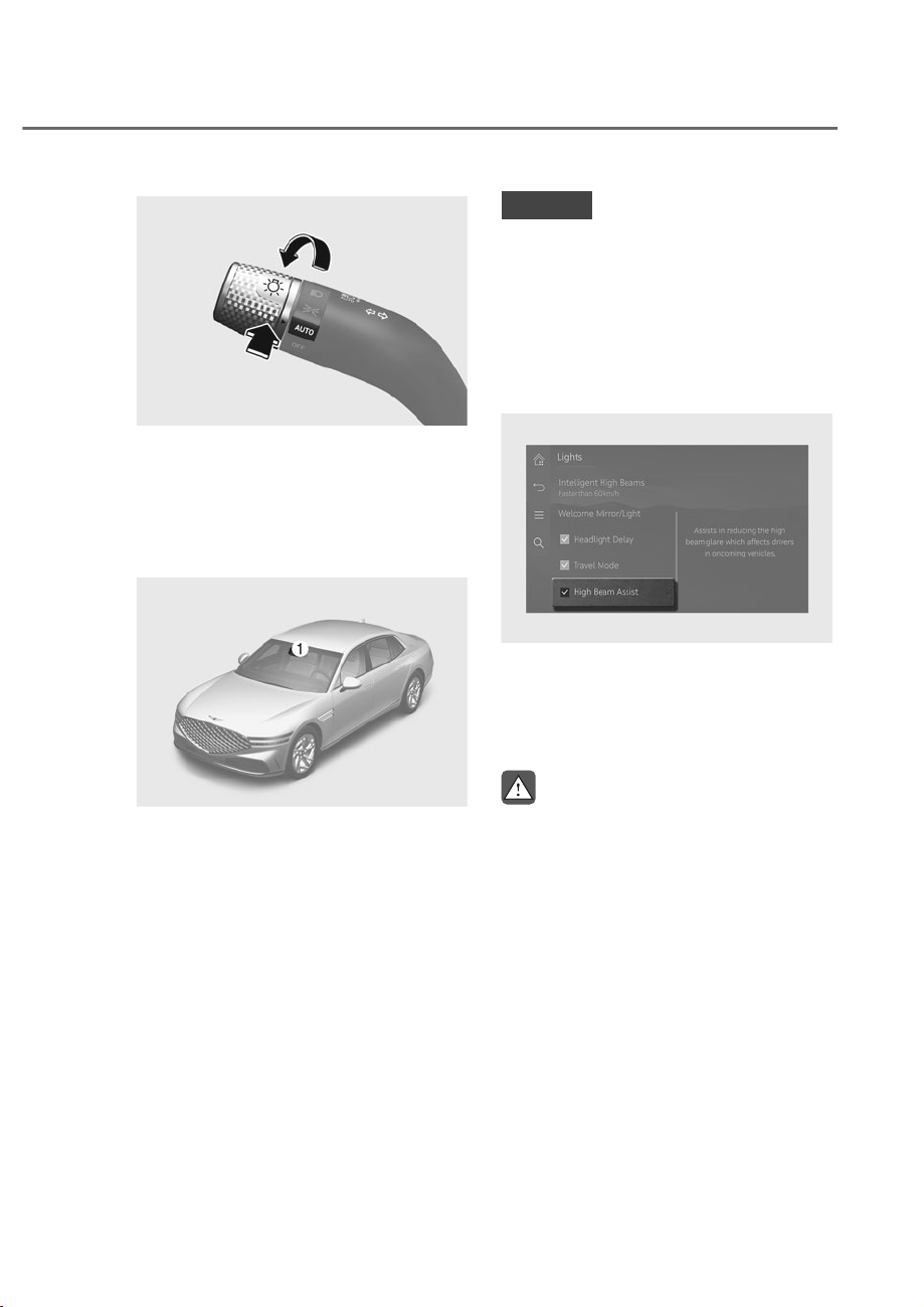
5-115
05
ORS051272
ORS051272
High Beam Assist will automatically
switch between high beam and low
beam depending on the detected
brightness from the lamps of oncoming
vehicles or vehicles in front.
Detecting sensor
ORS071001L
ORS071001L
M: Front view camera
The front view camera is used as a
detecting sensor to detect ambient light
and brightness while driving.
Refer to the picture above for the
detailed location of the detecting sensor.
NOTICE
Always keep the front view camera in
good condition to maintain optimal
performance of High Beam Assist.
)RUPRUHGHWDLOVRQWKHSUHFDXWLRQV
of the front view camera, refer to
ȃ)RUZDUG&ROOLVLRQ$YRLGDQFH$VVLVW
)&$ȄVHFWLRQLQFKDSWHUȾ
High Beam Assist Setting
ORS051241L
ORS051241L
With the Engine Start/Stop button in the
21SRVLWLRQVHOHFWȁ/LJKWVɌ+LJK%HDP
Assist’ from the Settings menu to turn on
High Beam Assist and deselect to turn off
the function.
WARNING
)RU\RXUVDIHW\FKDQJHWKH6HWWLQJV
after parking the vehicle at a safe
location.
+,*+%($0$66,67ʚ+%$ʛ

5-116
Convenience Features
High Beam Assist Operation
Display and control
• After selecting ‘High Beam Assist’
in the Settings menu, High Beam
Assist will operate by following the
procedure below.
- Place the headlight switch in
the AUTO position and push
the headlight lever towards the
instrument cluster. The High Beam
Assist (
) indicator light will
illuminate on the cluster and High
Beam Assist will be enabled.
- When High Beam Assist is enabled,
high beam will turn on when vehicle
speed is above 20 mph (30 km/h).
When vehicle speed is below 12
mph (20 km/h), high beam will turn
off.
- The High Beam (
) indicator light
will illuminate on the cluster when
high beam is on.
• When High Beam Assist is operating,
if the headlight lever or switch is used,
High Beam Assist operates as follow:
- If the headlight lever is pulled
towards you when the high beam
is off, the high beam will turn
on without High Beam Assist
cancelled. When you let go of the
headlight lever, the lever will move
to the middle and the high beam
will turn off.
- If the headlight lever is pulled
towards you when the high beam is
on by High Beam Assist, low beam
will turn on and High Beam Assist
will turn off.
- If the headlight switch is placed
from AUTO to another position
(headlight/position/off), High
Beam Assist will turn off and the
corresponding lamp will turn on.
• When High Beam Assist is operating,
high beam switches to low beam if
any of the following conditions occur:
- When the headlight of an oncoming
vehicle is detected.
- When the tail lamp of a vehicle in
front is detected.
- When the headlight or tail lamp of a
motorcycle or a bicycle is detected.
- When the surrounding ambient light
is bright enough that high beams
are not required.
- When streetlights or other lights are
detected.
Information
The images and colors in the instrument
cluster may differ depending on the cluster
type or theme selected from the settings
menu.
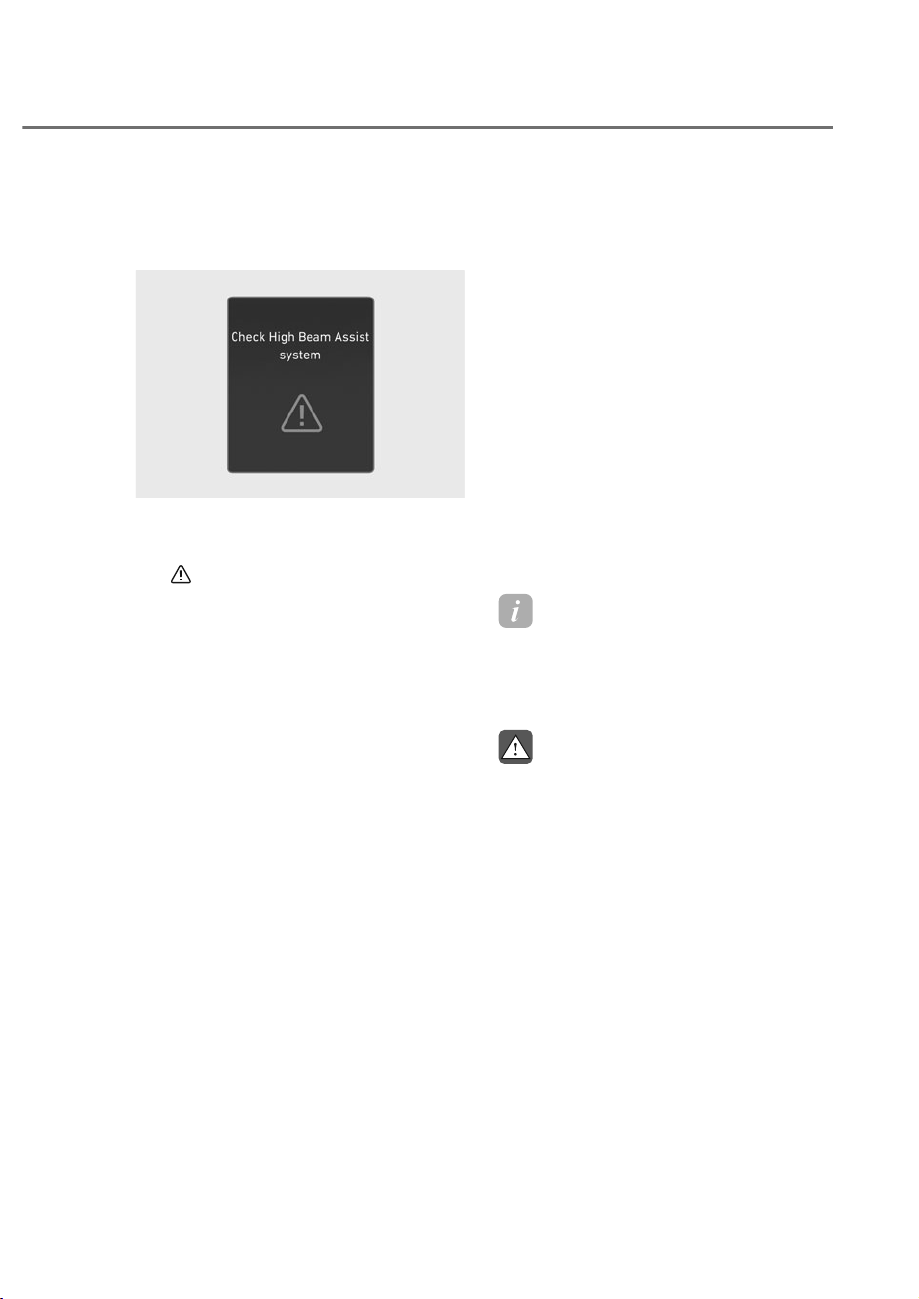
5-117
05
High Beam Assist Malfunction
and Limitations
High Beam Assist malfunction
OJWEV051094L
OJWEV051094L
When High Beam Assist is not working
properly, the ‘Check High Beam Assist
system’ warning message will appear
and
warning light will illuminate on
the cluster. Have the vehicle inspected
by an authorized retailer of Genesis
Branded products.
Limitations of High Beam Assist
• Light from an oncoming or front
vehicle is not detected because of
lamp damage, or because it is hidden
from sight, etc.
• Headlight of an oncoming or front
vehicle is covered with dust, snow or
water.
• An oncoming or front vehicle’s
headlights are off, but the fog lamps
are on, etc.
• There is a lamp that has a similar
shape as a vehicle’s lamp.
• Headlights have been damaged or not
repaired properly.
• Headlights are not aimed properly.
• Driving on a narrow-curved road,
curved road, rough road, uphill or
downhill.
• Vehicle in front is partially visible on a
crossroad or curved road.
• There is a traffic light, reflecting sign,
flashing sign or mirror ahead.
• There is a temporary reflector or flash
ahead (construction area).
• The road conditions are bad such as
being wet, iced or covered with snow.
• A vehicle suddenly appears from a
curve.
• The vehicle is tilted from a flat tire or
is being towed.
• Light from an oncoming or front
vehicle is not detected due to
obstacles in the air such as exhaust
fume, smoke, fog, snow, or water spay
or blizzard on the road, or fogging in
the lamp, etc.
Information
For more details on the limitations of the
)URQW9LHZ&DPHUDUHIHUWR³)RUZDUG
&ROOLVLRQ$YRLGDQFH$VVLVW)&$´VHFWLRQ
in chapter 7.
WARNING
• At times, High Beam Assist may not
work properly High Beam Assist is
for your convenience only. It is the
responsibility of the driver for safe
driving practices and always check
the road conditions for your safety.
• When High Beam Assist does not
operate properly, change the
headlight position manually between
high beam and low beam.
• When starting up or initializing the
front camera (rebooting, etc.), the
High Beam Assist function may not
work for about 15 seconds.
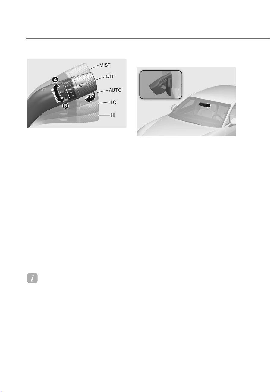
5-118
Convenience Features
ORS051284
ORS051284
)URQW:LQGVKLHOG:LSHUV
Operates as follows when the Engine
Start/Stop button is in the ON position.
MIST: For a single wiping cycle,
push the lever upward and
release. The wipers will operate
continuously if the lever is held in
this position.
OFF: Wiper is not in operation.
AUTO: The rain sensor located on the
upper end of the windshield
glass senses the amount of
rainfall and controls the wiping
cycle for the proper interval.
The more it rains, the faster the
wiper operates. When the rain
stops, the wiper stops. To vary
the speed setting, turn the speed
control knob.
LO: The wiper runs at a lower speed.
HI: The wiper runs at a higher speed.
Information
If there is heavy accumulation of snow
or ice on the windshield, defrost the
windshield for about 10 minutes, or until
the snow and/or ice is removed before
using the windshield wipers to ensure
proper operation.
If you do not remove the snow and/or ice
before using the wiper and washer, it may
damage the wiper and washer system.
AUTO (Automatic) control
ORS051085
ORS051085
The rain sensor located on the upper
end of the windshield glass senses
the amount of rainfall and controls the
wiping cycle for the proper interval.
The wiper operation time will be
automatically controlled depends on
rainfall.
When the rain stops, the wiper stops.
To vary the sensitivity setting, turn the
sensitivity control knob.
If the wiper switch is set in AUTO mode
when the Engine Start/Stop button is in
the ON position, the wiper will operate
once to perform a self-check of the
system. Set the wiper to the OFF position
when the wiper is not in use.
WIPERS AND WASHERS
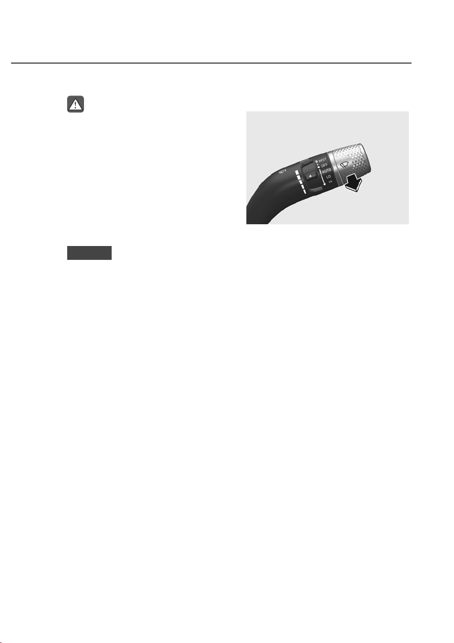
5-119
05
WARNING
To avoid personal injury from the
windshield wipers, when the engine
is running and the windshield wiper
switch is placed in the AUTO mode:
• Do not touch the upper end of the
windshield glass facing the rain
sensor.
• Do not wipe the upper end of the
windshield glass with a damp or wet
cloth.
• Do not put pressure on the
windshield glass.
NOTICE
• When washing the vehicle, set the
ZLSHUVZLWFKLQWKH2))SRVLWLRQWR
stop the auto wiper operation. The
wiper may operate and be damaged
if the switch is set in the AUTO mode
while washing the vehicle.
• Do not remove the sensor cover
located on the upper end of the
passenger side windshield glass.
Damage to system components
could occur and may not be covered
by your vehicle warranty.
• Because of using a photo sensor,
temporary malfunction could occur
according to sudden ambient light
change made by stone and dust
while driving.
Windshield Washers
ORG3EV051079
ORG3EV051079
In the OFF position, pull the lever gently
toward you to spray washer fluid on the
windshield.
The washer fluid is sprayed as the wipers
rise while operating. The spray and wiper
operation will continue until you release
the lever.
If the lever is released, the wipers
operate approximately 4 times and the
lever returns to it's original position

5-120
Convenience Features
Recirculating air when washer fluid
is used
When washer fluid is used, in order to
reduce any objectionable scent of the
washer fluid from entering the cabin,
recirculation mode and air conditioning
are automatically activated depending
on the outside temperature.
• When the air intake control button is
pressed while fresh mode is selected,
air intake control will switch to
recirculation mode.
• When windshield lever is used while
recirculation mode is selected, air
intake control will switch to fresh
mode
• The function may not work in some
conditions such as cold weather or
engine off.
For more details, refer to “Climate
Control Additional Features” section in
this chapter.
Information
)RU*DVROLQH7*',90+(9
vehicles, outside air may enter the vehicle
even while preventing washer fluid scent
IURPIORZLQJLQWKHFDELQWRFRROWKH9
battery.
WARNING
When the outside temperature is below
freezing, ALWAYS warm the windshield
using the defroster to help prevent
the washer fluid from freezing on the
windshield and obscuring your vision
which could result in an accident and
serious injury or death.
NOTICE
• To prevent possible damage to the
washer pump, do not operate the
washer when the fluid reservoir is
empty.
• To prevent possible damage to the
wipers or windshield, do not operate
the wipers when the windshield is
dry.
• To prevent damage to the wiper
arms and other components, do
not attempt to move the wipers
manually.
• To prevent possible damage to the
wipers and washer system, use anti-
freezing washer fluids in the winter
season or cold weather.
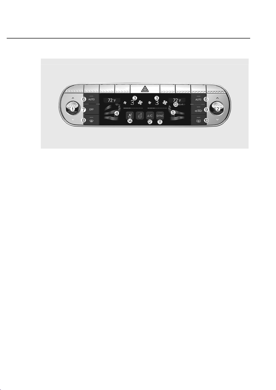
5-121
05
AUTOMATIC CLIMATE CONTROL SYSTEM
ORS052100N
ORS052100N
)URQWVHDWFRQWURO
1. Driver’s temperature control
2. Passenger’s temperature control
3. Fan speed control
4. Driver’s mode selection
5. Passenger’s mode selection
6. AUTO (automatic control)
7. OFF (system off)
8. Front windshield defroster
9. Air intake control
10.
Rear window defroster
11.
SYNC
12.
A/C (air conditioning)
13.
Rear control
14.
Built in diffuser
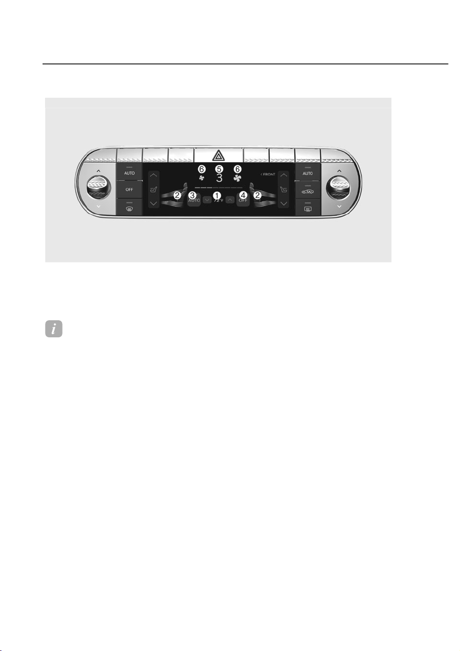
5-122
Convenience Features
Rear seat control from the front
1. Temperature control
2. Mode selection
3. AUTO (automatic control)
4. OFF (system off)
5. Climate control information screen
6. Fan speed control
ORS052102N
ORS052102N
Information
Use microfiber cloth when wiping finger prints off the touchscreen.
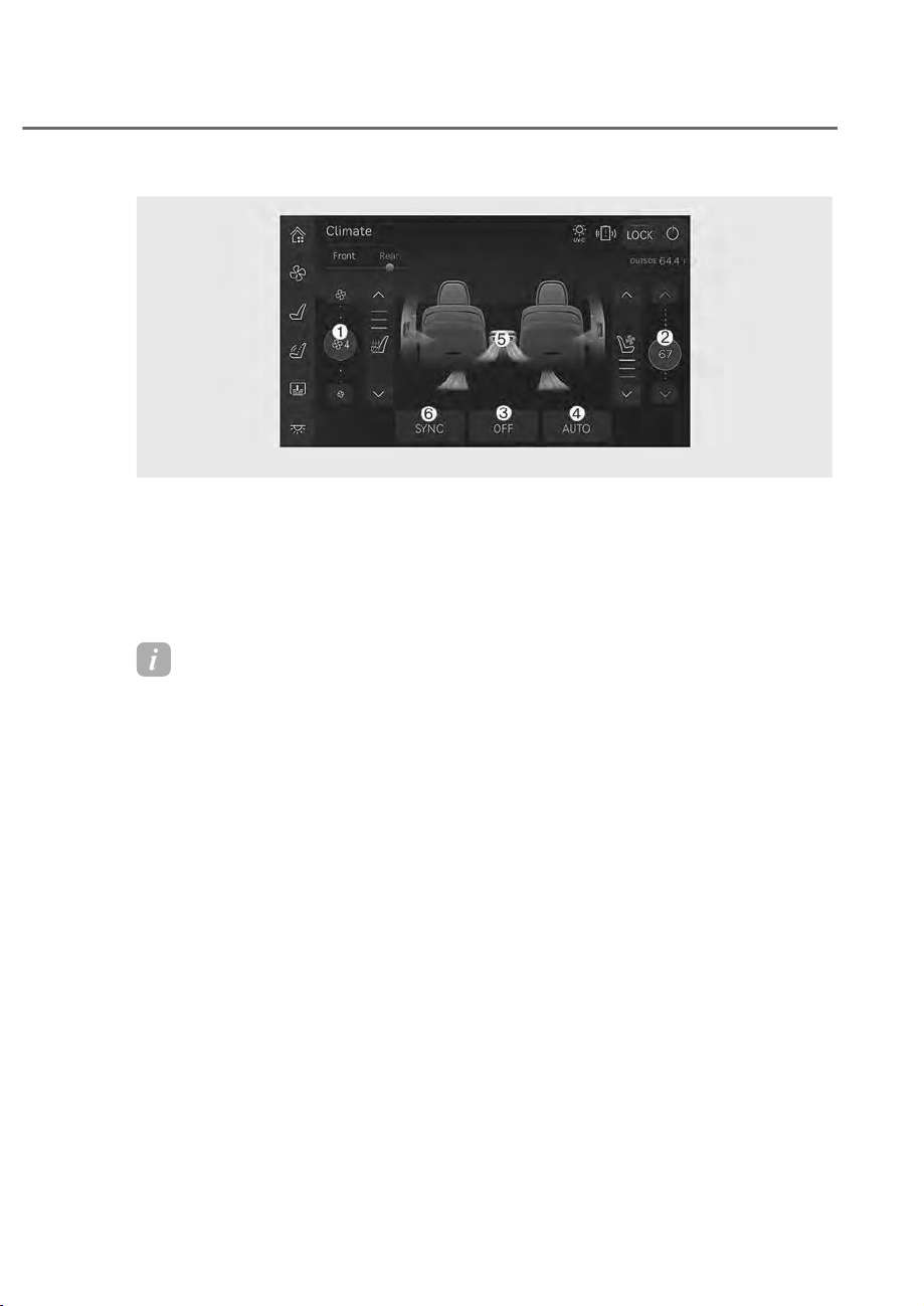
5-123
05
Rear seat control (Armrest touchscreen)
ORS052104N
ORS052104N
Information
• Press ‘Front’ and select the desired function from the rear armrest touchscreen to
access functions available on the front seats. The following functions are available.
- $872PRGHVHOHFWLRQWHPSHUDWXUHFRQWURODLULQWDNHFRQWUROIDQVSHHGFRQWURO
$&DQGGLIIXVHU
• 2SHUDWLQJWKHIDQVSHHGIURPWKHUHDUVHDWDGMXVWPHQWVFUHHQZLOORQO\RSHUDWHWKHUHDU
seat fan speed.
1. Fan speed control
2. Temperature control
3. OFF (system off)
4. AUTO (automatic control)
5. Mode selection
6. SYNC (Front and rear seats adjusted
same as the rear seat)
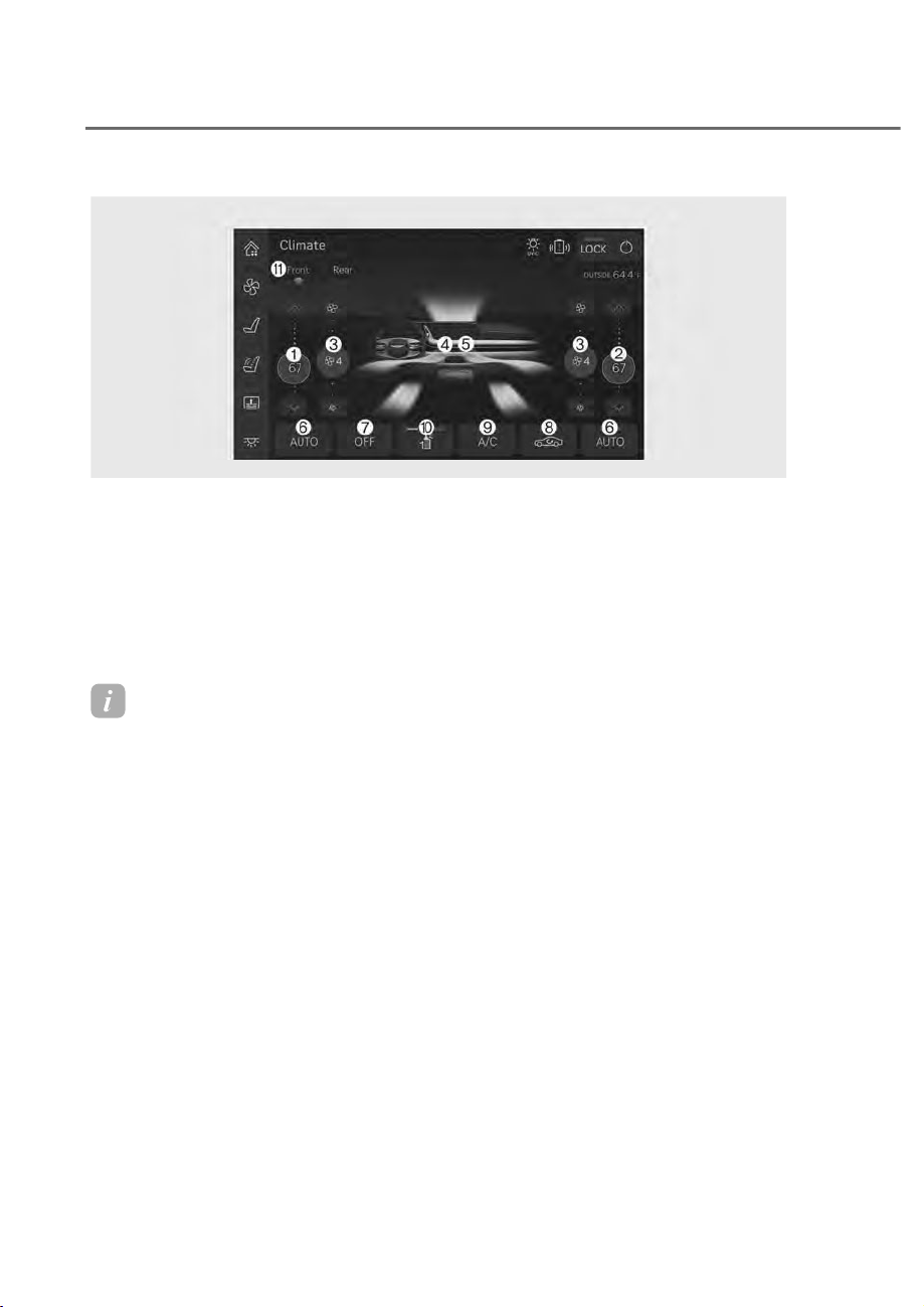
5-124
Convenience Features
1. Driver’s temperature control
2. Passenger’s temperature control
3. Fan speed control
4. Driver’s mode selection
5. Passenger’s mode selection
6. AUTO (automatic control)
7. OFF (system off)
8. Air intake control
9. A/C (air conditioning)
10.
Built in diffuser
11.
Front control
ORS052134N
ORS052134N
)URQWVHDWFRQWUROIURPWKHUHDU$UPUHVWWRXFKVFUHHQ
Information
2SHUDWLQJWKHIDQVSHHGIURPWKHIURQWVHDWDGMXVWPHQWVFUHHQZLOORQO\RSHUDWHWKHIURQW
seat fan speed.
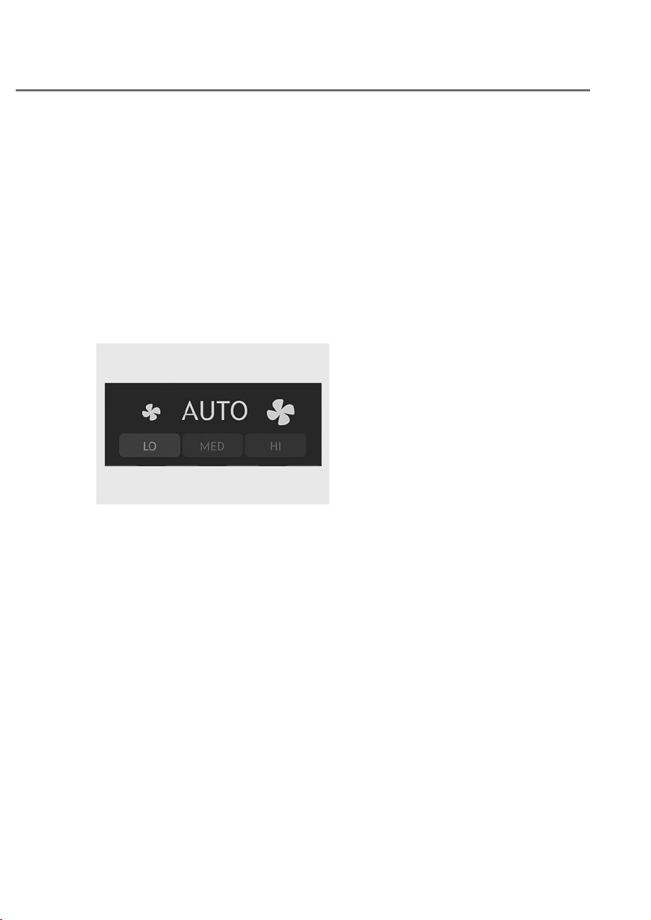
5-125
05
Automatic Temperature Control
Mode
The Automatic Climate Control System
is controlled by setting the desired
temperature.
1. Press the AUTO button.
The mode selection, fan speed,
air intake and air-conditioning will
be controlled automatically by the
temperature setting you select.
(To select the rear seat AUTO from
the front seat, press the icon in the
climate control information screen .)
ORS051144
ORS051144
2. When the climate control system is
being automatically controlled, fan
speed can be selected (Low/Medium/
High).
• High: Use when quick heating or
cooling is preferred.
• Medium: Use when medium fan
speed is preferred for cooling or
heating.
• Low: Use when low fan speed is
preferred for cooling or heating.
3. Turn the temperature control knob
to the desired temperature. If the
temperature is set to the lowest
setting (Lo), the air conditioning
system will operate continuously.
After the interior has cooled
sufficiently, adjust the knob to
a higher temperature set point
whenever possible.
To turn the automatic operation off,
select any function of the following:
• Front windshield defroster button
(Press the button one more time
to deselect the front windshield
defroster function. The ‘AUTO’
sign will illuminate on the climate
information screen once again.)
• Fan speed control icon
The selected function will be controlled
manually while other functions operate
automatically.
For your convenience and to improve the
efficiency of the climate control, use the
AUTO button and set the temperature to
72°F (22°C).
To change the temperature unit from °C
to °F or °F to °C:
Press the AUTO button for 3 seconds
while pressing the OFF button.
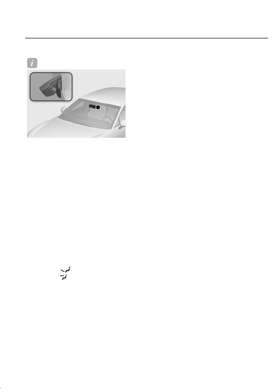
5-126
Convenience Features
Information
ORS051085
ORS051085
Never place anything near the ambient
light/solar sensor to ensure better control
of the heating and cooling system.
Manual Temperature Control
Mode
The heating and cooling system can be
controlled manually by pushing buttons
other than the AUTO button. In this case,
the system works sequentially according
to the order of buttons selected.
When pressing any button except the
AUTO button while using automatic
operation, the functions not selected will
be controlled automatically.
1. Start the vehicle.
2. Set the mode to the desired position.
To improve the effectiveness of
heating and cooling, select the mode
according to the following:
• Heating:
• Cooling:
3. Set the temperature control to the
desired position.
4. Set the air intake control to Fresh or
Recirculation mode.
5. Set the fan speed control to the
desired speed.
6. If air conditioning is desired, turn the
air conditioning system on.
7. Press the AUTO button to convert to
full automatic control of the system.
The climate control system settings
will be maintained, even when the
vehicle is turned OFF. However, the
climate control system settings will be
initialized when the battery has been
discharged, or when the cables have
been disconnected.
In this case, adjust the climate control
system settings again.
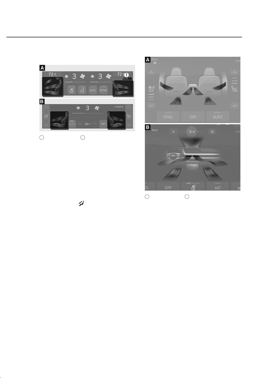
5-127
05
Mode selection
ORS052106N
ORS052106N
A
: Front seat control,
B
: Rear seat control
Front seat mode selection
• Touch each air flow direction on the
climate control information screen to
select the desired flow direction.
• Press the SYNC button and when
the indicator light on the button
turns off, the air flow direction of the
driver’s seat, passenger seat, and rear
seat can be controlled individually.
However, passengers and rear seats
cannot select
.
• Touch REAR M to control the second
row seat mode selection from the
front seats.
• You may select 2~3 modes at the
same time.
ORS051108
ORS051108
ORS051142L
ORS051142L
A
: Rear seat control,
B
: Front seat control
Rear seat mode selection
• Touch each air flow direction on the
armrest touchscreen to select the
desired air flow direction.
• Front seat air flow direction can be
selected individually for each seats.
• Air flow direction of the rear left and
right seats change together.
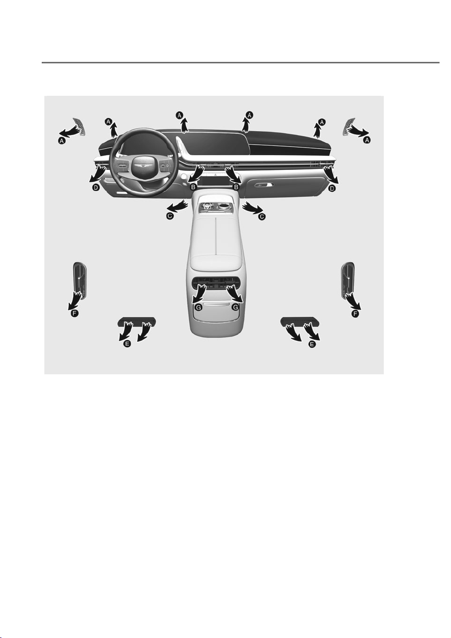
5-128
Convenience Features
ORS051109
Air flow direction
The mode selection icon or button controls the direction of the air flow through the
ventilation system.
Air flow direction F (if equipped) changes along with air flow direction G.

5-129
05
• Front seat air flow selected from the
front
Face-level (
B
,
D
)
Air flow is directed toward the upper
body.
Face-level (
A
,
B
,
D
)
Air flow is directed toward the upper
body and face.
Bi-Level (
B
,
&
,
D
)
Air flow is directed toward the upper
body and floor.
Bi-Level (
A
,
B
,
&
,
D
)
Air flow is directed toward the upper
body, face and floor.
Floor-level (
A
,
&
,
D
)
Most of the air flow is directed to the
floor, with a small amount of the air
being directed to the windshield and side
window defrosters. This air flow direction
is usually used when heating.
Bi-Level (
A
,
&
,
D
)
Most of the air flow is directed to the
floor, with a small amount of the air
being directed to the windshield and side
window defrosters.
Defrost (
A
,
D
)
Air flow is directed toward the face.
• Rear seat air flow selected from the
front
Face-level (
F
,
G
)
Air flow is directed toward the upper
body.
Bi-Level (
E
,
F
,
G
)
Air flow is directed toward the upper
body and floor.
Floor-level (
E
)
Most of the air flow is directed to the
floor, This air flow direction is usually
used when heating.
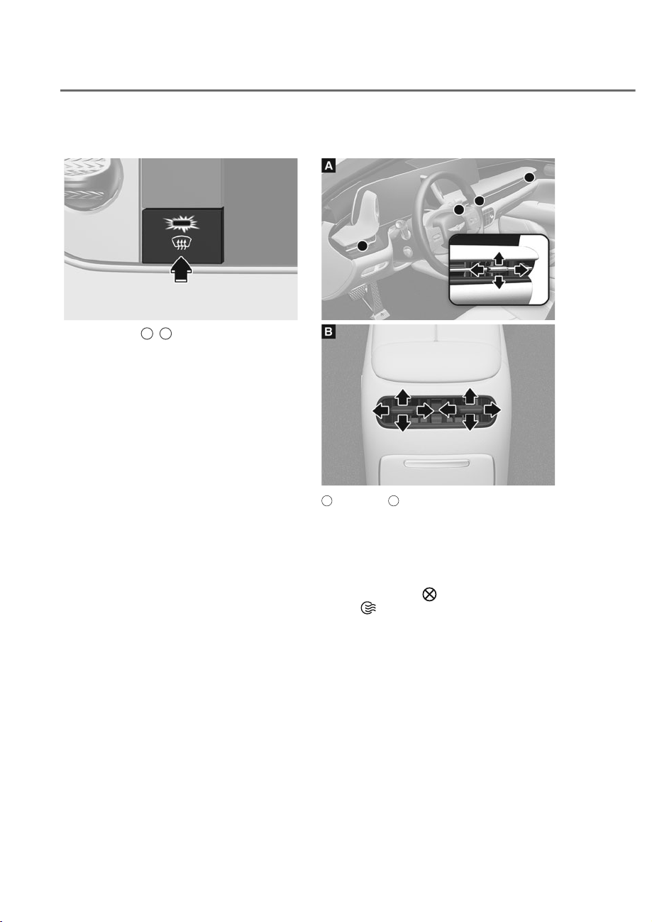
5-130
Convenience Features
Front windshield defroster
ORS051110
ORS051110
Defrost-level (
A
,
D
)
Press the button, and the indicator light
on the button will illuminate and the
windshield defroster indicator will appear
on the climate control information
screen.
Most of the air flow is directed to the
windshield with a small amount of air
directed to the side window defrosters.
When Defogging logic is enabled, Fresh
mode is selected and air conditioning
is selected according to outside
temperature.
Press the button again, the indicator light
will turn off and the previous settings will
be selected.
Instrument panel vents
ORS051111
ORS051111
ORS051112
ORS051112
A
: Front seat,
B
: Rear seat
The instrument panel vent air flow can be
directed up/down or left/right using the
vent adjustment lever.
The air flow can also be CLOSED using
the vent adjustment lever.
Move the lever to
position to close,
and to
position to open.
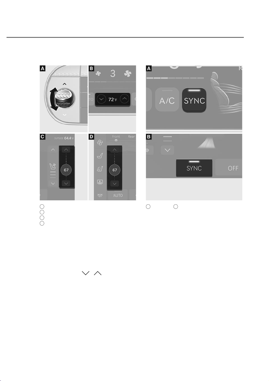
5-131
05
Temperature control
ORS052113N
ORS052113N
ORS052149N
ORS052149N
A
: Front seat control from the front,
B
: Rear seat control from the front,
C
: Rear seat control from the rear,
D
: Front seat control from the rear
Set the desired temperature using
the temperature control switch or the
icon button on the climate control
information screen.
• Push the switch up (red) to increase
the temperature. Push the switch
down (blue) to decrease temperature/
• Press the icon ( / ) in the
climate control information screen to
adjust the rear seat temperature from
the front seat.
• The temperature will increase or
decrease by 1°F (0.5°C) for each
incremental location. When set to
the lowest temperature setting,
the air conditioning will operate
continuously.
SYNC
ORS052117N
ORS052117N
ORS052136N
ORS052136N
A
: Front seat,
B
: Rear seat
$GMXVWLQJWKHWHPSHUDWXUHDLUIORZ
direction and fan speed equally
• Press the SYNC button (indicator
light ON) from the front seat, the
front and rear seat temperature, air
flow direction and fan speed will be
adjusted same as the driver’s control.
• Press the SYNC button (indicator
light ON) from the rear seat, the
front and rear seat temperature, air
flow direction and fan speed will
be adjusted same as the rear seat
control.
• The SYNC button does not operate
when the climate control system is off.
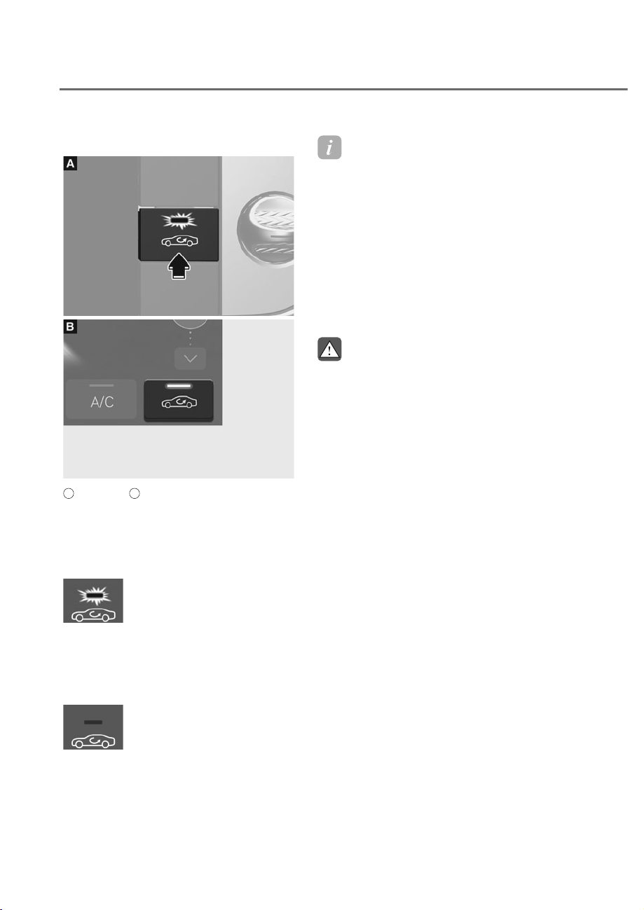
5-132
Convenience Features
Air intake control
ORS051118
ORS051118
ORS051137
ORS051137
A
: Front seat,
B
: Rear seat
The air intake control button is used to
select either Fresh mode (outside air) or
Recirculation mode (cabin air).
Recirculation mode
When Recirculation mode
is selected, air from the
passenger compartment will
be recirculated through the
system and heated or cooled
according to the function
selected.
Fresh mode
When Fresh mode is selected,
air enters the vehicle from
outside and is heated or
cooled according to the
function selected.
Information
2SHUDWLQJWKHV\VWHPSULPDULO\LQ)UHVK
mode is recommended. Use Recirculation
mode temporarily only when needed.
Prolonged operation of the heater in
Recirculation mode and without the air
FRQGLWLRQLQJ21FDQFDXVHIRJJLQJRIWKH
windshield. In addition, prolonged use of
WKHDLUFRQGLWLRQLQJ21LQ5HFLUFXODWLRQ
mode may result in excessively dry,
dehumidified air in the cabin and may
promote formation of musty vent odor due
to stagnant air.
WARNING
• Continued use of the climate control
system operation in Recirculation
mode for a prolonged period of
time may cause drowsiness to the
occupants in the cabin. This may lead
to loss of vehicle control which may
lead to an accident.
• Continued use of the climate control
system operation in Recirculation
PRGHZLWKWKHDLUFRQGLWLRQLQJ2))
may allow humidity to increase
inside the cabin. This may cause
condensation to accumulate on the
windshield and obscure visibility.
• Do not sleep in your vehicle or
remain parked in your vehicle with
the windows up and either the
heater or the air conditioning ON for
prolonged periods of time. Doing so
may increase the levels of carbon
dioxide in the cabin which may lead
to serious injury or death.
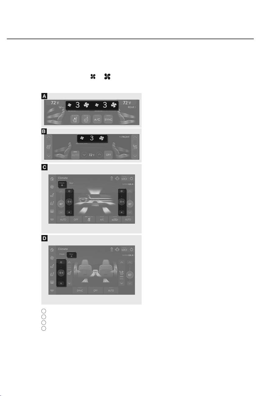
5-133
05
Fan speed control
The fan speed can be set to the desired
speed touching the
or icon on the
climate control information screen or
rear armrest touchscreen.
ORS052145N
ORS052145N
ORS052146N
ORS052146N
ORS052316N
ORS052316N
A
: Front seat control from the front,
B
: Rear seat control from the front,
C
: Front seat control from the rear,
D
: Rear seat control from the rear
When the front and rear fan speed can be
DGMXVWHG
The driver seat, front passenger seat, and
the rear seat fan speed can be adjusted
individually.
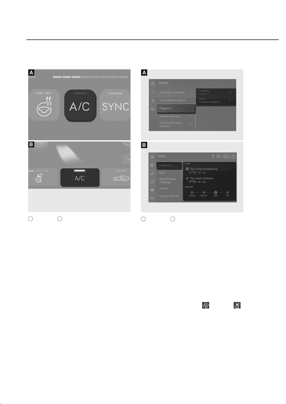
5-134
Convenience Features
Air conditioning
ORS052121N
ORS052121N
ORS052138N
ORS052138N
A
: Front seat,
B
: Rear seat
Touch the A/C icon to manually turn the
air conditioning on (indicator light on)
and off.
Built in diffuser (if equipped)
ORS051243L
ORS051243L
ORS051125L
ORS051125L
A
: Front seat,
B
: Rear seat
3 types of fragrances are provided.
The fragrance type is automatically
recognized when the cartridge is
installed.
Diffuser setting
Fragrance and its intensity can be set as
follows.
• ,QIRWDLQPHQWV\VWHP6HWXSɌ9HKLFOH
Ɍ&OLPDWHɌ)UDJUDQFHɌ,QWHQVLW\
Scent'
• 5HDUDUPUHVWWRXFKVFUHHQ+RPHɌ
6HWXSɌ)UDJUDQFHRU
Ɍ)URQWɌ
.
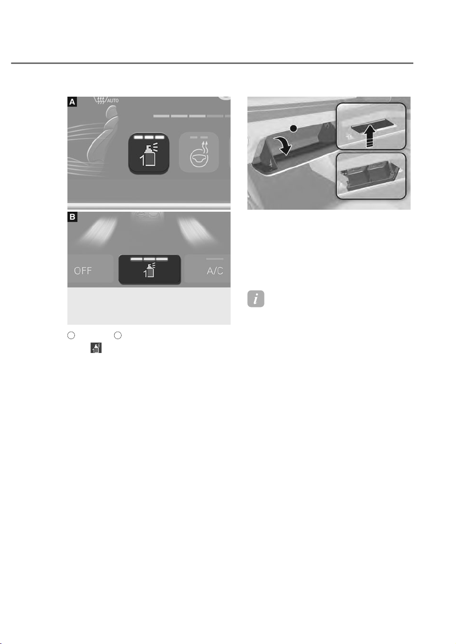
5-135
05
ORS051124
ORS051124
ORS051139L
ORS051139L
A
: Front seat,
B
: Rear seat
Press from the climate control
information screen or armrest
touchscreen to select the desired
fragrance intensity.
• Intensity can be selected among
Strong, Medium and Light. Pressing
the button each time will change
the intensity in the order of Strong,
Medium, Light and Off.
• The fragrance cannot be selected with
the button. Fragrance can only be
selected from the settings menu.
ORS051244
ORS051244
How to replace cartridges
1. Turn the engine off, and open the
glove box.
2. Press the upper part of the diffuser
tray.
3. Replace the cartridge.
Information
• For smooth operation of diffuser, it is
recommended to install 2 cartridges.
• If the cartridge is empty or diffuser
replacement alarm is displayed, replace
with a new cartridge.
• The built-in diffuser may not work if
the cartridge is not installed properly.
&KHFNZKHWKHUWKHFDUWULGJHLVLQVWDOOHG
properly.
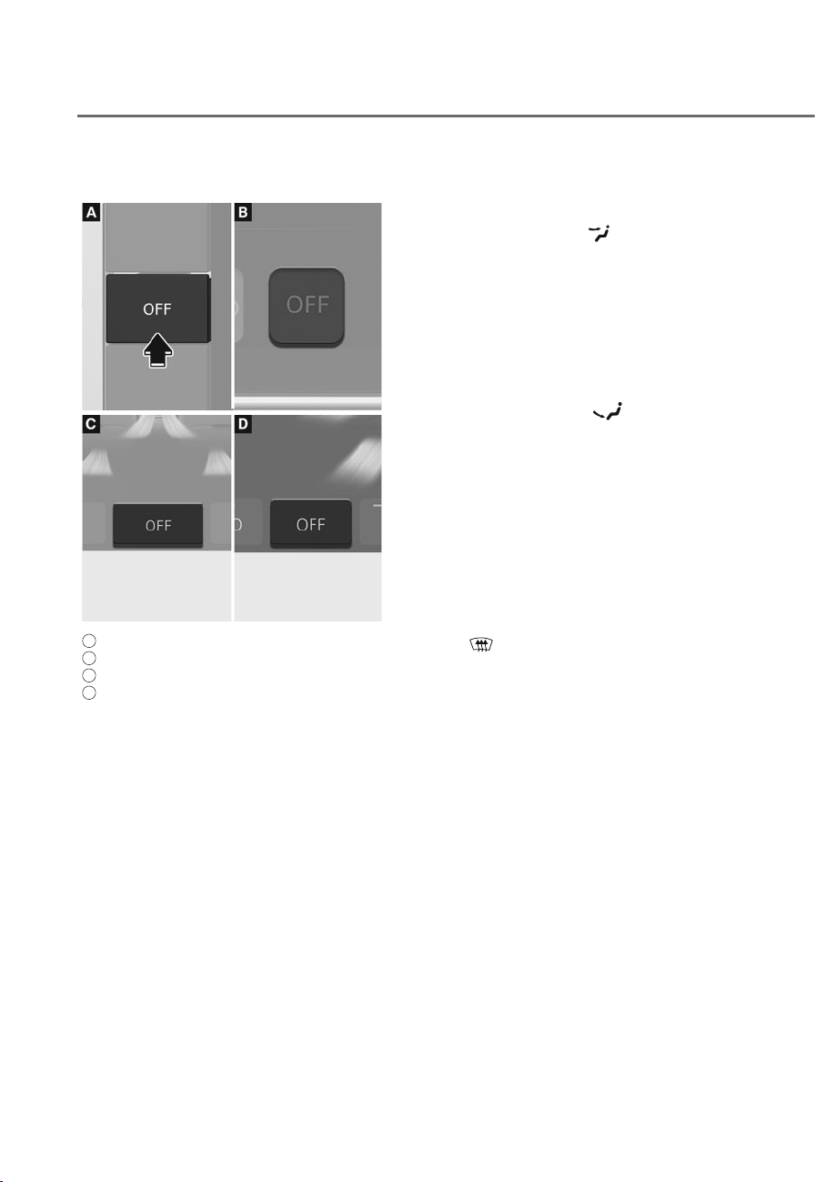
5-136
Convenience Features
OFF
ORS051126
ORS051126
ORS051128
ORS051128
A
: Front seat control from the front,
B
: Rear seat control from the front,
C
: Rear seat control from the rear,
D
: Front seat control from the rear
Touch the OFF icon or button to turn
the climate control system off. You can
still operate the mode and air intake
buttons as long as the Engine is in the
ON position.
• If OFF is pressed from the front seat,
the front and rear climate control
system will turn off.
• If OFF is pressed from the rear seat,
only the rear climate control system
will turn off.
System Operation
Cooling / Ventilation
1. Select the Face Level mode.
2. Set the air intake control to fresh or
recirculation mode.
3. Set the temperature control to the
desired position.
4. Set the fan speed control to the
desired speed.
Heating
1. Select the Floor Level mode.
2. Set the air intake control to fresh or
recirculation mode.
3. Set the temperature control to the
desired position.
4. Set the fan speed control to the
desired speed.
5. If desired, turn the air conditioning ON
with the temperature control knob set
to heat in order to dehumidify the air
before it enters into the cabin.
If the windshield fogs up, select the Front
Defrost
mode.
2SHUDWLRQ7LSV
• To keep dust or unpleasant fumes
from entering the vehicle through the
ventilation system, temporarily set the
air intake control to the recirculation
mode. Return the control to the to
Fresh mode when the unpleasant air
outside has diminished. This will help
keep the driver alert and comfortable.
• To help prevent the inside of the
windshield from fogging, set the air
intake control to fresh mode and the
fan speed to the desired position, turn
on the air conditioning system, and
adjust the temperature control to the
desired temperature.

5-137
05
Air conditioning
Your Genesis Branded Vehicle air
conditioning system is filled with
R-1234yf refrigerant.
1. Start the vehicle.
2. Press the air conditioning button.
3. Set the mode to the Face Level
mode.
4. Set the air intake control to
Recirculation mode temporarily to
allow the cabin to cool quickly. When
the desired temperature in the cabin
is reached, change the air intake
control back to Fresh mode.
5. Adjust the fan speed control and
temperature control to maintain
maximum comfort.
When maximum cooling is desired, set
the temperature control to the lowest
position, then set the fan speed control
to the highest setting.
NOTICE
When using the air conditioning system,
monitor the engine temperature gauge
closely while driving up hills or in heavy
traffic when outside temperatures are
high. Air conditioning system operation
when climbing a steep grade or in
high outside ambient temperatures
can cause engine overheating.
Continue to use the fan, but turn the air
conditioning system off if the engine
temperature gauge indicates engine
overheating.
Air conditioning system operation tips
• If the vehicle has been parked in
direct sunlight during hot weather,
open the windows for a short time
to let the hot air inside the vehicle
escape.
• After sufficient cooling has been
achieved, switch back from
recirculation mode to fresh mode.
• To help reduce moisture inside of
the windows on rainy or humid
days, decrease the humidity inside
the vehicle by operating the air
conditioning system with the windows
and sunroof closed.
• Use the air conditioning system
every month only for a few minutes
to ensure maximum system
performance.
• If you operate air conditioner
excessively, the difference between
the temperature of the outside air and
that of the windshield could cause
the outer surface of the windshield to
fog up, causing loss of visibility. In this
case, set the mode selection to the
position and fan speed control to the
lowest speed.
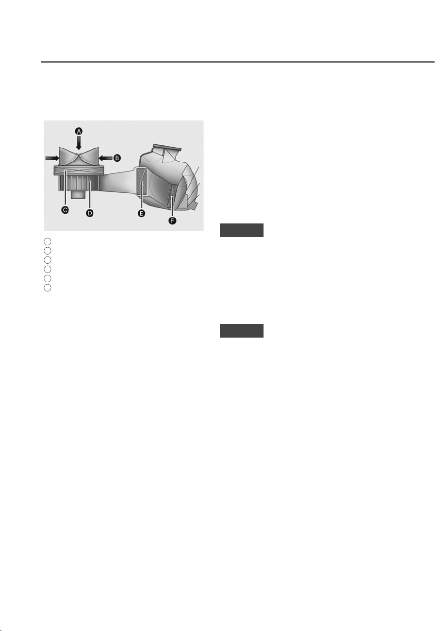
5-138
Convenience Features
System Maintenance
Cabin air filter
OHI048581L
OHI048581L
A
: Outside air,
B
: Recirculated air,
C
: Climate control air filter,
D
: Blower,
E
: Evaporator core,
F
: Heater core
The cabin air filter is installed behind
the glove box. It filters the dust or other
pollutants that enter the vehicle through
the heating and air conditioning system.
We recommend that the cabin air filter
be replaced by an authorized retailer of
Genesis Branded products according to
the maintenance schedule. If the vehicle
is being driven in severe conditions such
as dusty or rough roads, more frequent
cabin air filter inspections and changes
are required.
If the air flow rate suddenly decreases,
have the system inspected at an
authorized retailer of Genesis Branded
products.
Checking the amount of air
conditioner refrigerant and
compressor lubricant
When the amount of refrigerant is low,
the performance of the air conditioning
is reduced. Overfilling also reduces the
performance of the air conditioning
system.
Therefore, if abnormal operation is
found, have the system inspected by an
authorized retailer of Genesis Branded
products.
NOTICE
It is important that the correct type and
amount of oil and refrigerant is used.
Otherwise, damage to the compressor
and abnormal system operation may
occur. To prevent damage, the air
conditioning system in your vehicle
should only be serviced by trained and
certified technicians.
NOTICE
• The refrigerant system should only
be serviced by trained and certified
technicians to insure proper and safe
operation.
• The refrigerant system should be
serviced in a well-ventilated place.
• The air conditioning evaporator
(cooling coil) shall never be repaired
or replaced with one removed from
a used or salvaged vehicle and new
replacement MAC evaporators shall
be certified (and labeled) as meeting
SAE Standard J2842.
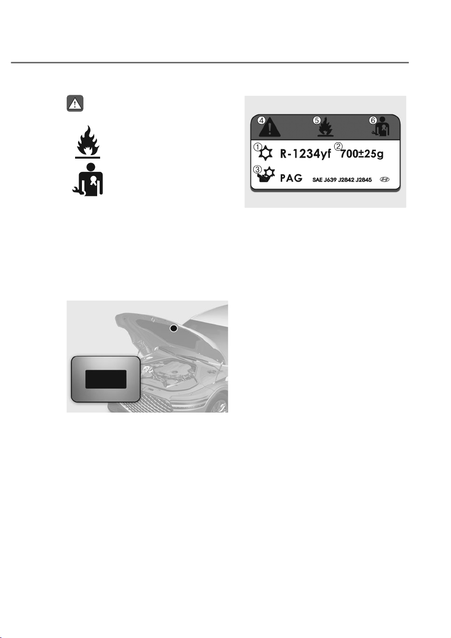
5-139
05
WARNING
Vehicles equipped with R-1234yf
Since the refrigerant is
mildly flammable and
operated at high pressure,
the air conditioning system
should only be serviced
by trained and certified
technicians. It is important
that the correct type and
amount of oil and refrigerant
are used.
All refrigerants should be reclaimed
with proper equipment.
Venting refrigerants directly to the
atmosphere is harmful to individuals
DQGHQYLURQPHQW)DLOXUHWRKHHGWKHVH
warnings can lead to serious injuries.
Air Conditioning refrigerant label
ORS052129N
ORS052129N
You can find out which air conditioning
refrigerant is applied to your vehicle on
the label located inside of the hood.
ORS051226
ORS051226
Each symbols and specification on
the air conditioning refrigerant label is
represented as below:
M Classification of refrigerant
N Amount of refrigerant
O Classification of compressor lubricant
P Caution
Q Flammable refrigerant
R
To require registered technician to
service air conditioning system
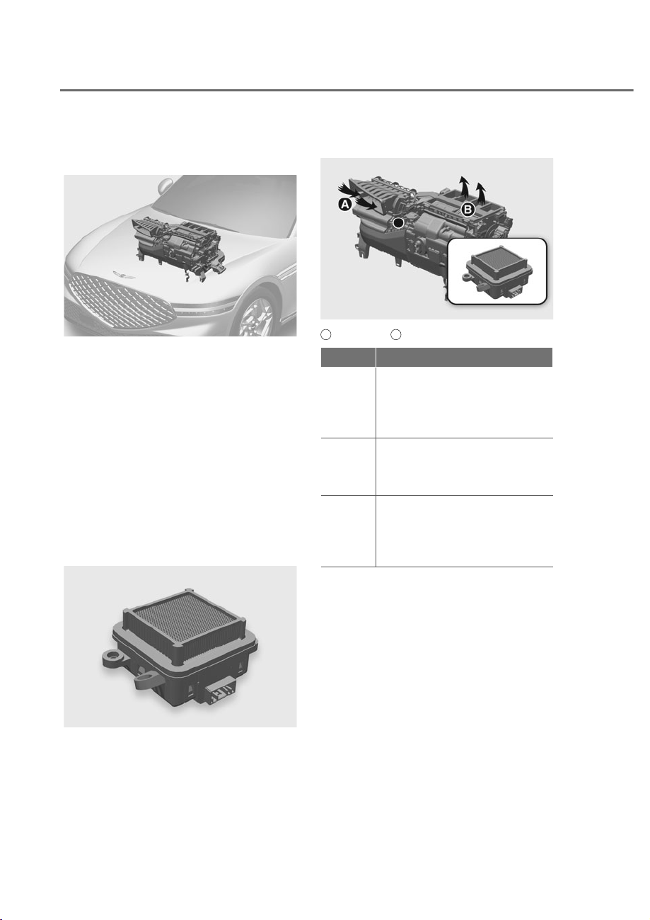
5-140
Convenience Features
Photo-catalyst Module ( if
equipped )
ORS052329N
ORS052329N
Freshens a vehicle’s inner space by
deodorization of lingering odor through
PCM installed in HVAC system.
Your Genesis is equipped with the PCM
which includes a visible ray LED and
photo-catalytic material. The PCM is
activated automatically when the vehicle
is started.
The PCM deodorizes harmful gases
such as NH
3
or HCHO and reduces the
number of floating viruses and bacteria
nearby PCM and eventually air inside
cabin of your vehicle will be refreshed
by continuous air flow through PCM
installed in HVAC system.
ORS052326N
ORS052326N
Ex) 2HCHO + 2H
2
O + 2O
2
J 2CO
2
+ 4H
2
O
• Photocatalytic radical reaction
J
Removal of harmful substances
(VOC gases/microorganisms)
Air cleaning mechanism
ORS052328N
ORS052328N
A
: Outdoor air,
B
: Clean air
Part )XQFWLRQ
HVAC
Intakes indoor and outdoor
air into the HVAC, passes it
through the PCM, and then
supplies clean air to the interior
of the vehicle.
PCM
The visible ray LED photo-
catalyst module produces
radicals by photocatalytic
reaction.
Radicals
Radicals generated by the PCM
attach to viruses, bacteria and
harmful gases such as NH
3
and
HCHO and reduce the number
of them in HVAC system.
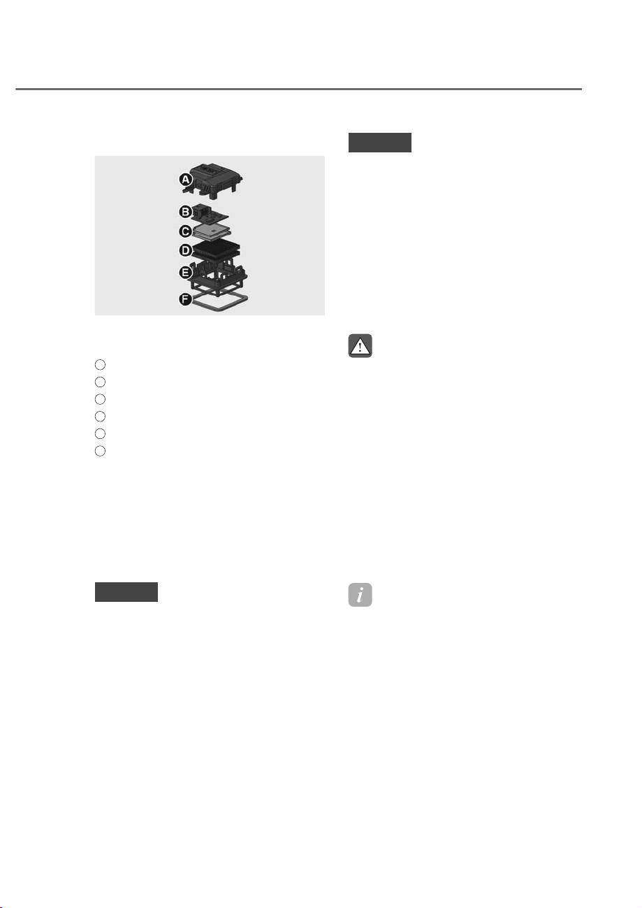
5-141
05
PCM parts
ORS052327N
ORS052327N
- Size: 2x2x1 in. (53x53x27 mm)
- Weight: 1.6 oz (46 g)
A
: Upper cover
B
: PCB & Connector
C
: Water protection PCB cover
D
: Photo-catalyst
E
: Lower cover
F
: Leakage protection seal
Direction for use
The PCM, Photo-catalyst Air Purifier
Module for HVAC is activated
automatically when the engine of
automobile is started and deactivated
automatically when the engine is turned
off.
NOTICE
• Do not disassemble, modify or
repair. Any changes or modifications
to product can void your
manufacturer’s warranty.
• If you need servicing, visit a
designated service center.
• Do not use the product for anything
other than its original purpose.
• Do not drop or cause excessive
impact to the product.
• Do not apply any other substances
on the photo catalyst surface.
• If water is on the product, dry it
thoroughly before using it.
NOTICE
• Disposal
Dispose of contents and containers
according to the regulations
stipulated in the wastes control act.
• Storage
- Do not store near acids. As packed
massive products may constitute a
manual handling risk. (e.g., sharp)
- Do not store in areas with high
concentrations of dust or airborne
materials.
WARNING
• This product should be sold
only through and be installed by
automobiles. Other uses are not
acceptable device.
• PCM may be particularly helpful
when additional ventilation with
outdoor air is not possible without
compromising indoor comfort
(temperature or humidity), or when
outdoor air pollution is high.
• The use of PCM alone cannot
ensure adequate indoor air quality,
particularly where significant
pollutant sources are present, and
ventilation is insufficient.
Information
(3$FRPSDQ\QXPEHU.25
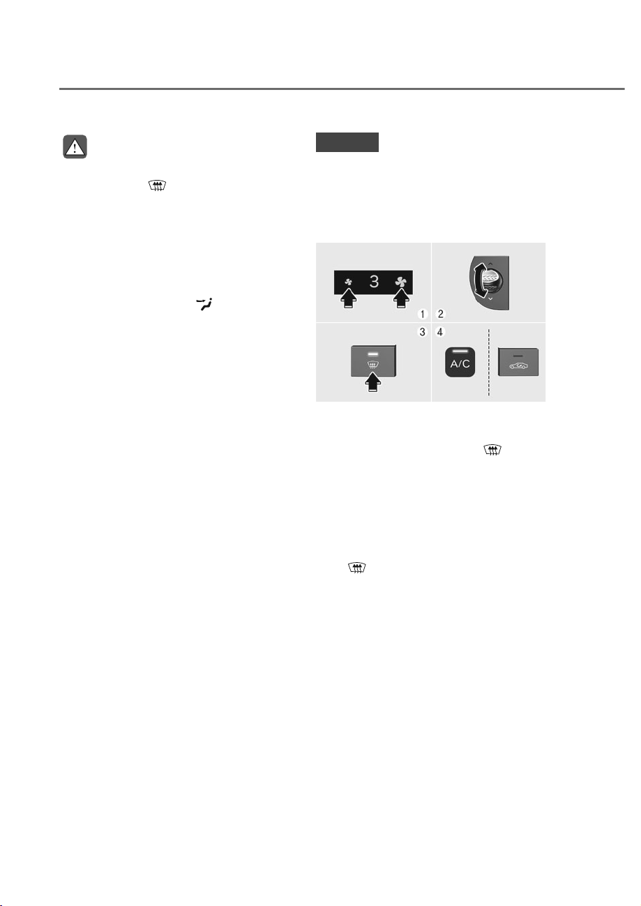
5-142
Convenience Features
WARNING
Windshield heating
Do not use the
position during
cooling operation in extremely humid
weather. The difference between the
temperature of the outside air and that
of the windshield could cause the outer
surface of the windshield to fog up,
causing loss of visibility could cause
an accident resulting in serious injury
or death. In this case, set the mode
selection button to the
position
and fan speed control knob to a lower
speed.
• For maximum defrost performance,
set the temperature control to the
highest temperature setting and
the fan speed control to the highest
setting.
• If warm air to the floor is desired while
defrosting or defogging, set the mode
to the floor-defrost position.
• Before driving, clear all snow and ice
from the windshield, rear window,
side view mirrors and all side
windows.
• Clear all snow and ice from the
hood and air inlet in the cowl grill
to improve heater and defroster
efficiency and to reduce the
probability of fogging up the inside of
the windshield.
NOTICE
If the engine temperature is still cold
after starting, then a brief engine warm
up period may be required for the
vented air flow to become warm or hot.
To Defog Inside Windshield
ORS051131L
ORS051131L
1. Select the desired fan speed.
2. Select the desired temperature.
3. Press the defroster button (
).
4. Fresh mode will be selected
automatically.
Check to make sure the air intake control
is in Fresh mode. If the air intake control
indicator light is illuminated, press the
button once to enable Fresh mode
(indicator light OFF).
If the
position is selected, the fan
speed is automatically increased.
:,1'6+,(/''()5267,1*$1''()2**,1*
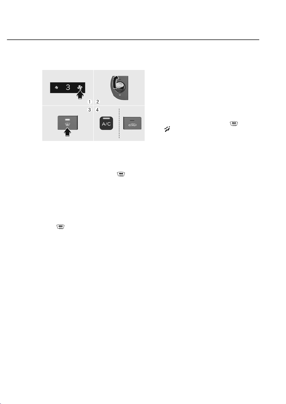
5-143
05
To Defrost Inside Windshield
ORS051130
ORS051130
1. Set the fan speed to the highest
(extreme right) position.
2. Set the temperature to the extreme
hot (HI) position.
3. Press the defroster button (
).
4. Fresh mode will be selected
automatically.
Check to make sure the air intake control
is in Fresh mode. If the air intake control
indicator light is illuminated, press the
button once to enable Fresh mode
(indicator light OFF).
If the
position is selected, lower fan
speed is adjusted to a higher fan speed.
Defogging Logic
To reduce the probability of fogging
up the inside of the windshield, the air
intake or air conditioning are controlled
automatically according to certain
conditions. To cancel or reset the
defogging logic, do the following.
1. Press the Engine Start/Stop button to
the ON position.
2. Press the defroster button (
) or
(
).
3. While pressing the air conditioning
button (A/C), press the air intake
control button at least 5 times within
3 seconds.
The air intake control button indicator
will blink 3 times to indicate that the
defogging logic has been disabled.
Repeat the steps again to re-enable the
defogging logic.
If the battery has been discharged or
disconnected, it resets to the defog logic
status.
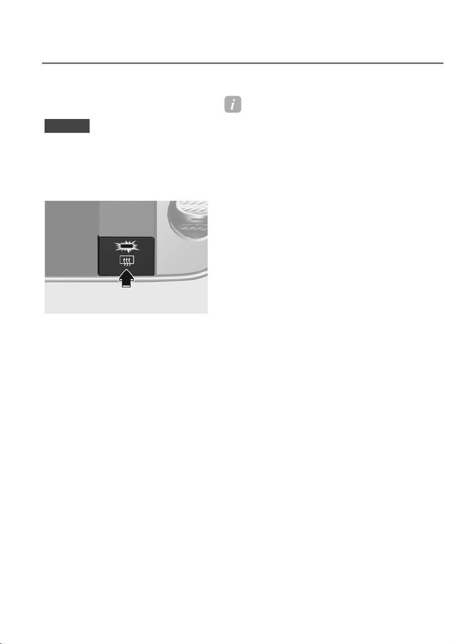
5-144
Convenience Features
Rear Window Defroster
NOTICE
To prevent damage to the rear window
defroster conducting elements bonded
to the inside surface of the rear window,
never use sharp instruments or window
cleaners containing abrasives to clean
the window.
ORS051132
ORS051132
The defroster heats the window to
remove frost, fog and thin ice from the
interior and exterior of the rear window,
while the engine is running.
• To activate the rear window defroster,
press the rear window defroster
button located in the center control
panel. The indicator on the rear
window defroster button illuminates
when the defroster is ON.
• To turn off the defroster, press the rear
window defroster button again.
Information
• If there is heavy accumulation of snow
on the rear window, brush it off before
operating the rear defroster.
• The rear window defroster
automatically turns off after
approximately 20 minutes or when the
(QJLQH6WDUW6WRSEXWWRQLVLQWKH2))
position.
Side view mirror defroster
If your vehicle is equipped with the side
view mirror defrosters, they will operate
at the same time you turn on the rear
window defroster.
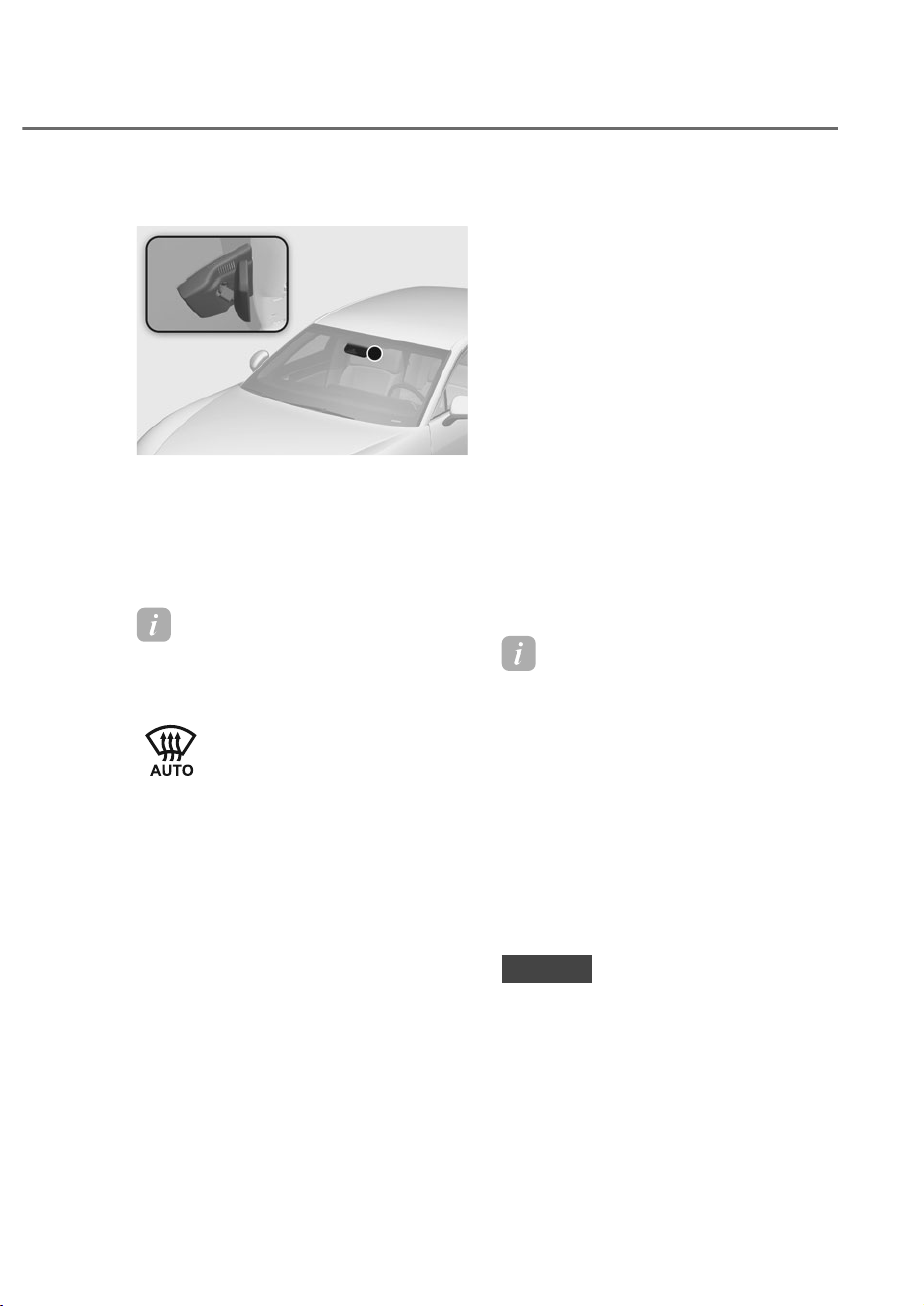
5-145
05
Auto Defogging System
ORS051085
ORS051085
Auto defogging helps reduce the
possibility of fogging up the inside of the
windshield by automatically sensing the
moisture on inside the windshield.
The auto defogging system operates
when the heater or air conditioning is on.
Information
The auto defogging system may not
operate normally, when the outside
WHPSHUDWXUHLVEHORZ)&
When the Auto Defogging
System operates, the indicator
will illuminate.
If a high amount of humidity is detected
in the vehicle, the Auto Defogging
System will be enabled. The following
steps will be performed automatically:
Step 1) Air conditioning will turn ON.
Step 2) Air intake control will change to
Fresh mode.
Step 3) Mode will change to defrost to
direct airflow to the windshield.
Step 4) Fan speed will be set to MAX.
If the air conditioning is off or
recirculation mode is manually selected
while Auto Defogging System is ON, the
Auto Defogging System indicator will
blink 3 times to signal that the manual
operation has been canceled.
Turning the Auto Defogging System
ON or OFF
&OLPDWHFRQWUROV\VWHP
Press the front windshield defroster
button for 3 seconds when the Engine
Start/Stop button is in the ON to turn the
system on or off.
To check whether the system is on
or off, go to the settings menu in the
infotainment system and see if 'Auto
Defog' is selected or not.
Infotainment system
Auto Defogging System can be turned
RQDQGRIIE\VHOHFWLQJȁ6HWXSɌ9HKLFOHɌ
&OLPDWHɌ'HIRJ'HIURVW2SWLRQVɌ$XWR
Defog’ from the infotainment system
screen.
See additional information in supplied
Infotainment Manual.
Information
• When the air conditioning is turned
on by Auto Defogging System, if you
try to turn off the air conditioning, the
indicator will blink 3 times and the air
conditioning will not be turned off.
• To maintain the effectiveness and
efficiency of the Auto Defogging
System, do not select Recirculation
mode while the system is operating.
• When Auto Defogging System is
RSHUDWLQJIDQVSHHGDGMXVWPHQW
WHPSHUDWXUHDGMXVWPHQWDQGDLULQWDNH
control selection are all disabled.
NOTICE
Do not remove the sensor cover located
on the upper end of the windshield
glass.
Damage to system parts could occur
and may not be covered by your vehicle
warranty.
&/,0$7(&21752/$'',7,21$/)($785(6

5-146
Convenience Features
Auto Dehumidify (if equipped)
To increase cabin air quality and reduce
windshield misting, recirculation mode
switches off automatically after about 5
to 30 minutes, depending on the outside
temperature, and the air intake will
change to fresh mode.
Turning Auto Dehumidify ON or OFF
&OLPDWHFRQWUROV\VWHP
To turn the Auto Dehumidify feature
on or off, select Face level (
) mode
and press the air intake control (
)
button at least five times within three
seconds. When Auto Dehumidify is
turned on, the air intake control button
indicator will blink 6 times. When turned
off, the indicator will blink 3 times.
Infotainment system
Auto Dehumidify can be turned on
DQGRIIE\VHOHFWLQJȁ6HWXSɌ9HKLFOH
Ɍ&OLPDWHɌ$XWRPDWLF9HQWLODWLRQ
Ɍ$XWRPDWLF'HKXPLGLI\ȂIURPWKH
infotainment system screen.
See additional information in supplied
Infotainment Manual.
Recirculating Air When Washer
)OXLGLV8VHG
Recirculation mode automatically
activates to reduce any objectionable
scent of the washer fluid from entering
the cabin when the windshield washer is
used.
Turning Activate upon Washer Fluid
Use ON or OFF
&OLPDWHFRQWUROV\VWHP
To turn the Activate upon Washer Fluid
Use feature on or off, select Floor level
(
) mode, and then press the air
intake control (
) button four times
within two seconds while pressing the
A/C icon.
When Activate upon Washer Fluid Use
ON is turned on, the air intake control
button indicator will blink 6 times. When
turned off, the indicator will blink 3
times.
Infotainment system
Activate upon Washer Fluid Use can be
turned on and off by selecting ‘Setup
Ɍ9HKLFOHɌ&OLPDWHɌ5HFLUFXODWH$LU
Ɍ$FWLYDWHXSRQ:DVKHU)OXLG8VHRU
Interlocking washer fluid)’ from the
infotainment system screen.
See additional information in supplied
Infotainment Manual.
However, in cold weather to prevent
the windshield from fogging up, the
recirculation mode may not be selected.

5-147
05
Sunroof Inside Air Recirculation
(if equipped)
When the is sunroof opened, fresh
mode will be automatically selected.
At this time, if you press the air intake
control button, recirculation mode will
be selected but will change back to fresh
mode after 3 minutes. When the sunroof
is closed, the air intake position will
return to the original position that was
selected.
Automatic Controls Linked to
Climate Control Settings (for
driver’s seat)
The temperature of the driver’s seat
warmer, air ventilated seat and heated
steering wheel is automatically
controlled depending on the inside and
outside temperature of the vehicle when
the engine is running.
To use these features, it must be
enabled from the Settings menu in the
infotainment system screen. Select:
- 6HWXSɌ9HKLFOHɌ6HDWɌ+HDWHG
9HQWLODWHG)HDWXUHVɌ+HDWHG
9HQWLODWHG)HDWXUHVɌ$XWRPDWLF
Controls Linked to Climate Control
Settings
For more details on Auto Comfort
Control, refer to “Seat Warmers” and “Air
ventilation seats” section in chapter 3
and “Heated Steering Wheel” section in
chapter 5.
Recirculation Mode Plus (if
equipped)
• To prevent the inflow of polluted
air into the vehicle when passing
through a tunnel, this function
automatically closes the windows and
switches the climate control system
to Recirculation mode for about 7
seconds before entering a tunnel
based on the map information of
the navigation and the speed of the
vehicle.
• The windows automatically closes
before entering a tunnel and area
requiring air recirculation. The
windows open to the previous
position after passing the area. If the
power window switch is operated
before the window opens, the
window does not open to the previous
position.
• To use this feature, it must be enabled
from the Settings menu in the
infotainment system screen. Select:
- 6HWXSɌ9HKLFOHɌ&OLPDWHɌ
5HFLUFXODWH$LUɌ5HFLUFXODWLRQ0RGH
Plus
See additional information in supplied
Infotainment Manual.
Operating Condition
• Type of road: Freeway, highway,
expressway
• Vehicle status: One or more of the
windows are opened or fresh mode is
selected

5-148
Convenience Features
Information
• The activation time for the
recirculation mode may differ
depending on the gap between the GPS
data and vehicle speed.
• The function will not activate again
when tunnels exist continuously.
• When entering a tunnel, recirculation
mode may cause fogging of the
windshield. Press the windshield
defrosting button.
• After exiting the tunnel, fresh mode
may be selected depending on the air
condition inside the vehicle.
• The function does not operate in
tunnels within 50m in length.
• The function may not activate if the
GPS is not working properly.
Recirculation Mode (if equipped)
• To prevent the inflow of polluted
air into the vehicle when passing
through a tunnel or air polluted
area, this function automatically
switches the climate control system
to Recirculation mode for about 7
seconds before entering a tunnel or
air polluted area based on the map
information of the navigation and the
speed of the vehicle.
• To use this feature, it must be enabled
from the Settings menu in the
infotainment system.
Select:
- 6HWXSɌ9HKLFOHɌ&OLPDWHɌ
5HFLUFXODWH$LUɌ3RRU$LU4XDOLW\
Area
See additional information in supplied
Infotainment Manual.
Operating Condition
• Type of road: Freeway, highway,
expressway
• Vehicle status: Fresh mode is selected
Information
• The activation time for the
recirculation mode may differ
depending on the gap between the GPS
data and vehicle speed.
• The function will not activate again
when tunnels exist continuously.
• When entering a tunnel, recirculation
mode may cause fogging of the
windshield. Press the windshield
defrosting button.
• After exiting the tunnel, fresh mode
may be selected depending on the air
condition inside the vehicle.
• The function does not operate in
tunnels within 50m in length.
• The function may not activate if the
GPS is not working properly.
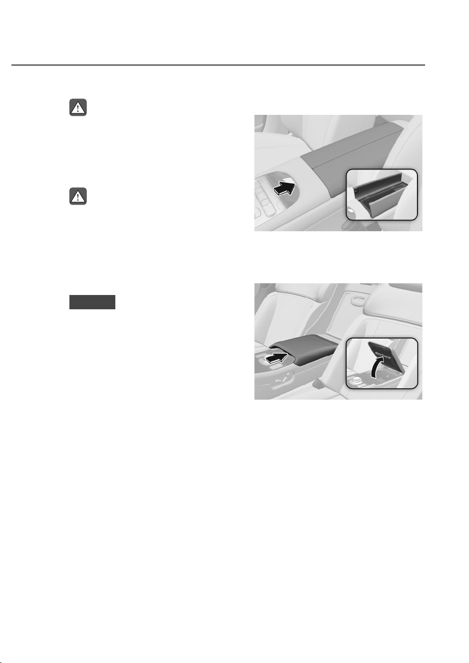
5-149
05
STORAGE COMPARTMENT
WARNING
Never store cigarette lighters, propane
cylinders, or other flammable/explosive
materials in the vehicle. These items
may catch fire and/or explode if the
vehicle is exposed to hot temperatures
for extended periods.
WARNING
ALWAYS keep the storage compartment
covers closed securely while driving.
Items inside your vehicle are moving as
fast as the vehicle. If you have to stop
or turn quickly, or if there is a crash, the
items may fly out of the compartment
and may cause an injury if they strike
the driver or a passenger.
NOTICE
To avoid possible theft, do not leave
valuables in the storage compartments.
Center Console Storage
ORS051086
ORS051086
To open:
Press the button.
Rear Console Storage
ORS052087N
ORS052087N
To open:
Press the button.
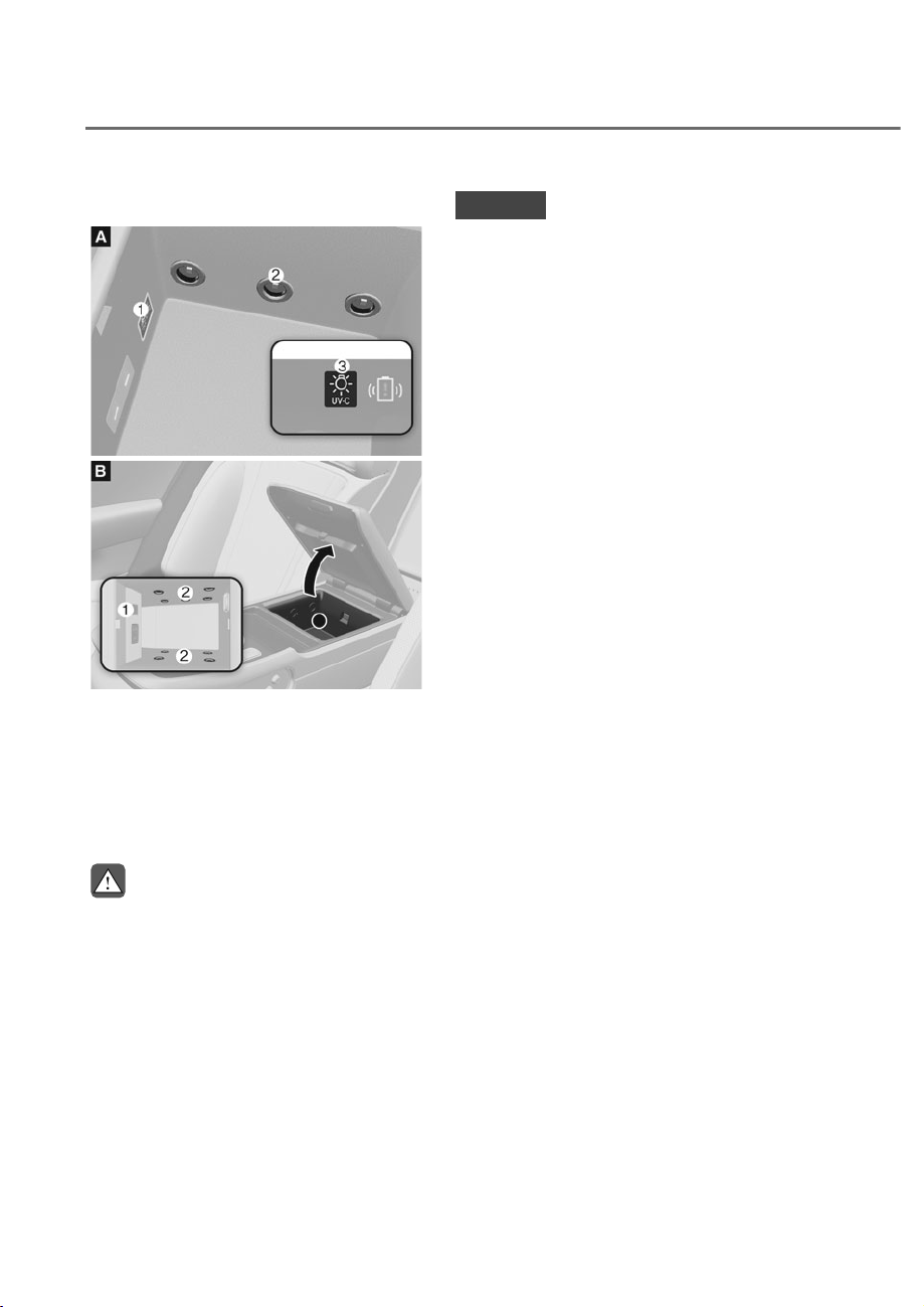
5-150
Convenience Features
UV-C sterilizer system
ORS051092
ORS051092
ORS051229
ORS051229
M: UV-C sterilizer system button,
N: UV-C LED,
O
: UV-C Indicator light (upper part of armrest
touchscreen)
The rear seat console is equipped with
an antibacterial sterilization system for
personal belongings.
WARNING
• Press the button to turn UV-C
function off when it is not in use.
Being exposed to ultraviolet rays
from UV-C LED may be harmful to
your skin and eyes.
• Do not place magnetic items
(magnets, etc.) near the upper part
of the UV-C storage box. It may cause
malfunction to the UV-C sensor and
unnecessarily operate the UV-C
function.
NOTICE
• Press the button to turn UV-C
function off when it is not in use.
Prolonged exposure under ultraviolet
rays may change the color and shape
of the object.
• 'RQRWVWHULOL]HIRRG)RRGFDQQRW
be sterilized. Prolonged exposure
to ultraviolet rays may damage the
wrapping or container and affect the
food inside.
Using UV-C sterilizer system
Place the item in the UV-C storage box
and turn it on. Within 10 minutes, up to
99.9% of germs on the surface can be
removed.
1. Open the UV-C storage box while the
engine is running.
2. Press the button inside the storage
box.
• UV-C sterilizer system indicator light
illuminates.
• Antibacterial tray is ready to
operate.
3. Place the item in the center inside the
storage box and close the cover.
• UV-C indicator light illuminates.
• UV-C LED is turned on and
sterilization begins.
• After 10 minutes, the UV-C indicator
light turns off as sterilization is
complete.
• Press the UV-C sterilizer system
button to turn off the function, after
you are finished using the system.
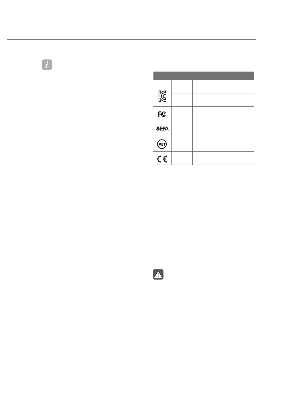
5-151
05
Information
• 2QO\SODFHWKHLWHPZKLFKUHTXLUHV
sterilization. Storing other items in the
storage box may reduce the sterilization
effect.
• 89&VWHULOL]HUV\VWHPGRHVQRW
guarantee 99.9% sterilization. The
sterilization effect varies depending on
WKHGHJUHHRIH[SRVXUHWR89&OLJKW
and the shape of the item. For effective
use, change the position of the item and
run additional sterilization.
• 89&LQGLFDWRUOLJKWEOLQNVRUGRHVQRW
operate properly, visit an authorized
retailer of Genesis Branded products.
Unit item verification number
Unit item verification number
Type A
Registration Number:
R-R-HdG-89910-T4AHO
Type B
Registration Number:
R-R-EpS-846R0-T4000
Type A
DECLARATION OF
CONFORMITY
Type A
ESTABLISHMENT
NUMBER: 100891-KOR-1
CUS
Type A
LISTING NUMBER:
E115351
Type
A/B
DECLARATION OF
CONFORMITY
• This appliance is not intended for use
by persons (including children) with
reduced physical, sensory or mental
capabilities, or lack of experience
and knowledge, unless they have
been given supervision or instruction
concerning use of the appliance by a
person responsible for their safety.
• For your safety, this appliance
complies with the applicable
standards and regulations (Low
Voltage Directive, Electromagnetic
Compatibility, Environmental, etc.
• This product uses the vehicle’s battery
voltage and should be used only at DC
9 V-16 V.
WARNING
This product emits ultraviolet rays. Do
not gaze upon the UV rays while using
the product. Exposing the eyes or skin
to UV rays may have harmful effect to
the body.
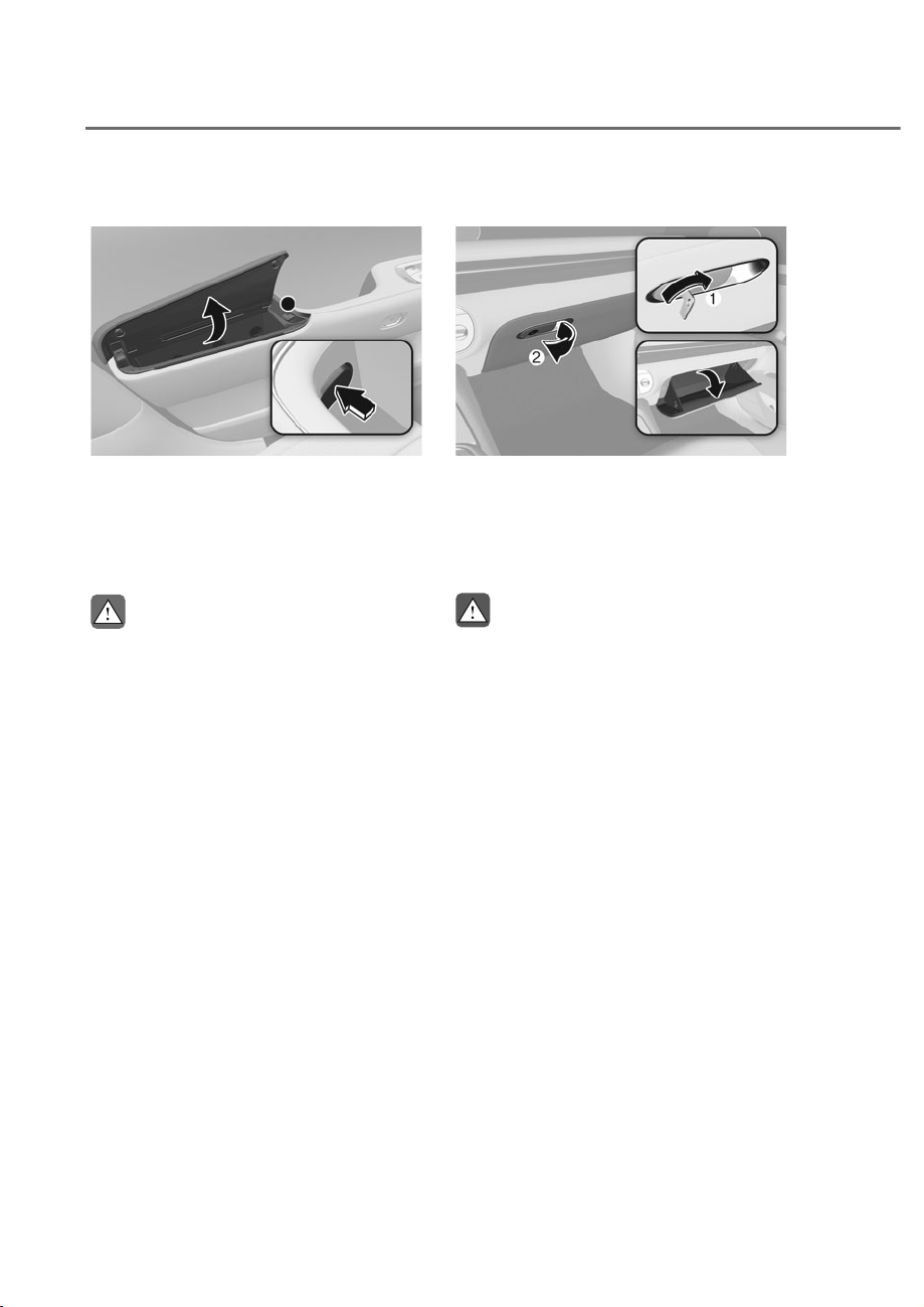
5-152
Convenience Features
Armrest Storage Box
ORS051088
ORS051088
Use to store small items.
To open:
Press the button that is located inside of
the door handle.
CAUTION
Always press the button to open the
VWRUDJHER[)RUFLEO\RSHQLQJWKH
storage box may cause damage.
Glove Box
ORS051090
ORS051090
The glove box can be locked and
unlocked with the mechanical key M.
To open:
Pull the lever N.
WARNING
ALWAYS close the glove box door after
use.
An open glove box door can cause
serious injury to the passenger in an
accident, even if the passenger is
wearing a seat belt.
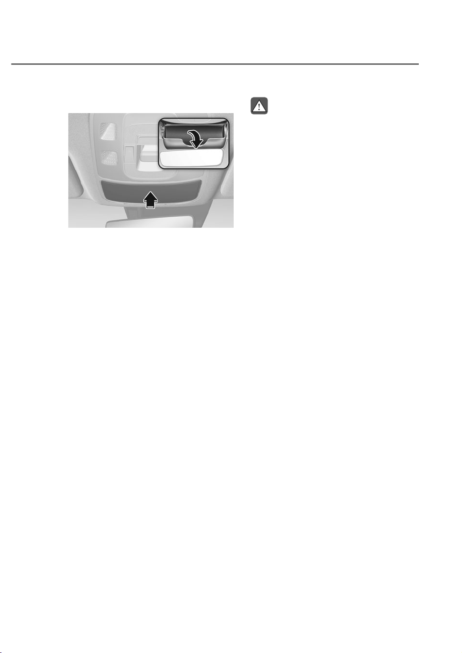
5-153
05
Sunglass Holder
ORS051296L
ORS051296L
To open:
Push and release the cover and the
holder will slowly open. Place your
sunglasses in the compartment door
with the lenses facing out.
To close:
Push back into position.
Make sure the sunglass holder is closed
while driving.
WARNING
• Do not keep objects except
sunglasses inside the sunglass
holder. Such objects can be thrown
from the holder in the event of a
sudden stop or an accident, possibly
injuring the passengers in the
vehicle.
• Do not open the sunglass holder
while the vehicle is moving. The side
view mirror of the vehicle can be
blocked by an open sunglass holder.
• Do not put the glasses forcibly into
a sunglass holder. It may cause
personal injury if you try to open
it forcibly when the glasses are
jammed in holder.
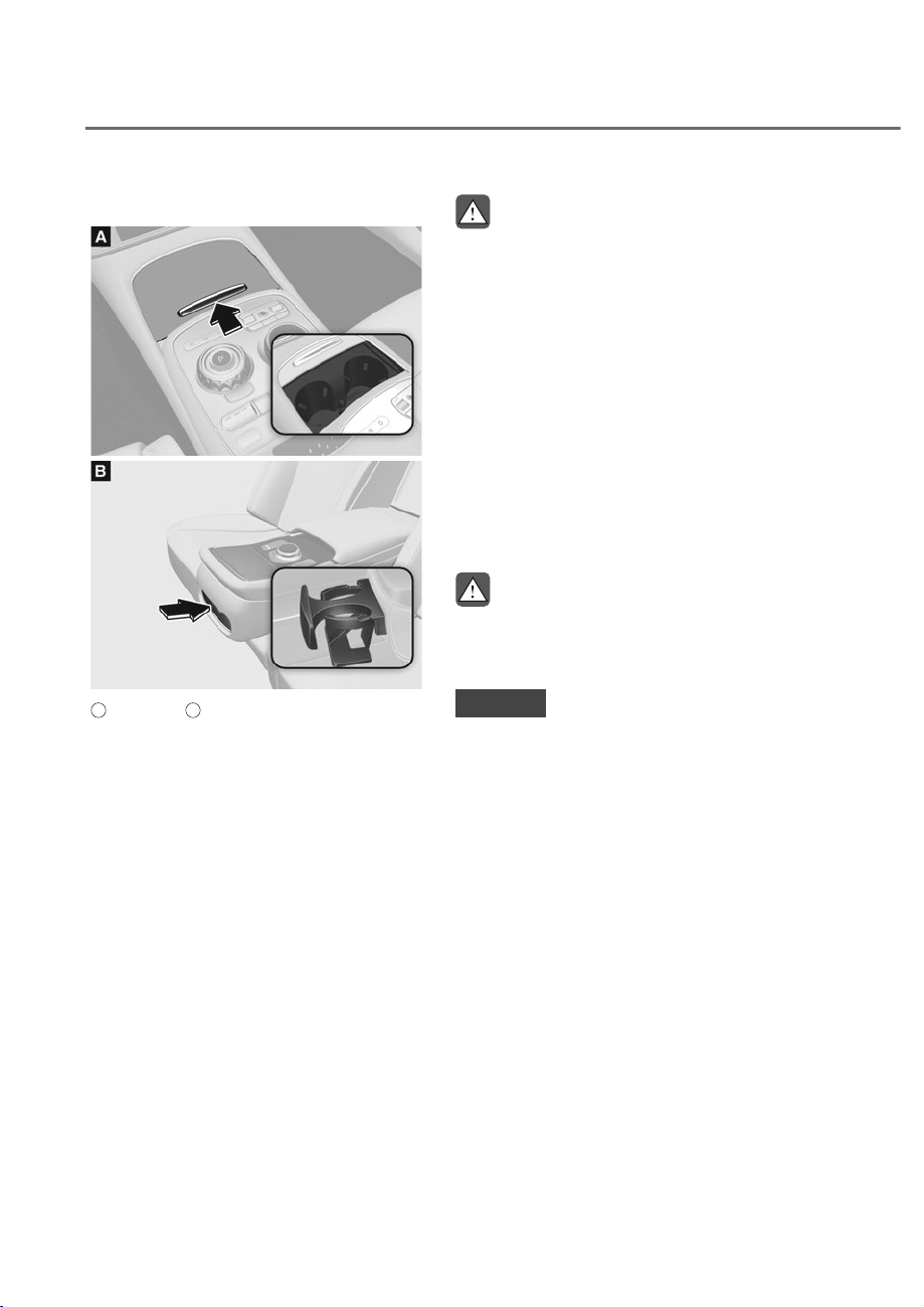
5-154
Convenience Features
,17(5,25)($785(6
Cup Holder
ORS051094
ORS051094
ORS051093
ORS051093
A
: Front seat,
B
: Rear seat
Cups or small beverages cups may be
placed in the cup holders.
Front seat:
Push the cover up and it will slowly open.
Push it up once more to to close the
cover.
Rear seat:
Push the cover. The cover will slide open.
WARNING
• Avoid abrupt starting and braking
when the cup holder is in use to
prevent spilling your drink. If hot
liquid spills, you could be burned.
Such a burn to the driver could cause
loss of vehicle control resulting in an
accident.
• Do not place uncovered or unsecured
cups, bottles, cans, etc., in the cup
holder containing hot liquid while
the vehicle is in motion. Injuries may
result in the event of a sudden stop
or collision.
• Only use soft cups in the cup holders.
Hard objects can injure you in an
accident.
WARNING
Keep cans or bottles out of direct sun
light and do not put them in a hot
vehicle. It may explode.
NOTICE
• Keep your drinks sealed while
driving to prevent spilling your drink.
If liquid spills, it may get into the
vehicle’s electrical/electronic system
and damage electrical/electronic
parts.
• When cleaning spilled liquids do not
use hot air to blow out or dry the cup
holder. This may damage the interior.
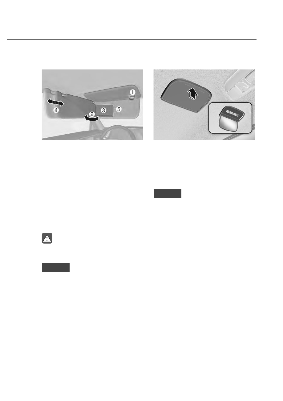
5-155
05
Sunvisor
ORS051275
ORS051275
To use the sunvisor, pull it downward.
To use the sunvisor to block the sun
from the side window, pull it downward,
release it from the bracket M and swing it
to the side N towards the window.
To use the vanity mirror, pull down the
sunvisor and slide the mirror cover O.
Adjust the sunvisor forward or backward
P as needed (if equipped). Use the ticket
holder Q to hold tickets.
Close the vanity mirror cover securely
and return the sunvisor to its original
position after use.
WARNING
)RU\RXUVDIHW\GRQRWEORFN\RXUYLHZ
when using the sunvisor.
NOTICE
The tab Q adjacent to the vanity mirror
on the sunvisor can be used for toll
road tickets or self parking tickets. Use
caution when inserting tickets into the
ticket holder to avoid damage. Refrain
from putting several tickets in the ticket
holder as this could also damage the
retaining tab.
Rear Mirror
ORS051095
ORS051095
To open:
Press the cover and it will slowly open
and the mirror lamp will turn on.
To close:
Push back into position.
NOTICE
Make sure to close the rear mirror
cover after use. If not, the rear mirror
lamp remains ON, possibly draining the
battery or damaging the rear mirror.
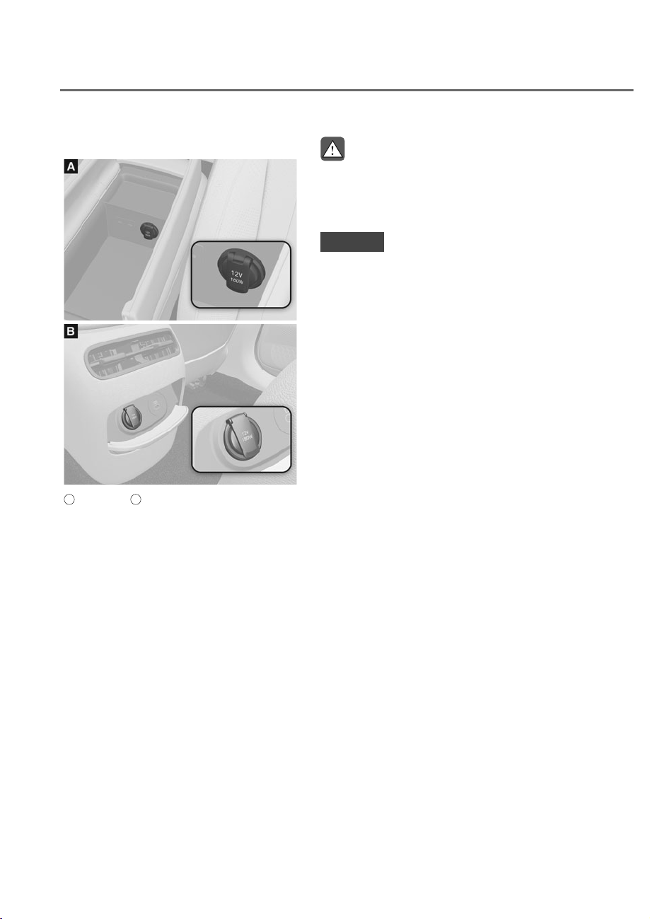
5-156
Convenience Features
Power Outlet
ORS051096
ORS051096
ORS051097
ORS051097
A
: Front seat,
B
: Rear seat
The power outlet is designed to provide
power for mobile telephones or other
devices designed to operate with vehicle
electrical systems. The devices should
draw less than 180 W with the engine
running.
WARNING
Avoid electrical shocks. Do not place
your fingers or foreign objects (pin, etc.)
into a power outlet or touch the power
outlet with a wet hand.
NOTICE
To prevent damage to the power
outlets:
• Use the power outlet only when the
engine is running and remove the
accessory plug after use. Using the
accessory plug for prolonged periods
of time with the engine off could
cause the battery to discharge.
• Only use 12V electric accessories
which are less than 180 W in electric
capacity.
• Adjust the air-conditioner or heater
to the lowest operating level when
using the power outlet.
• Close the cover when not in use.
• Some electronic devices can
cause electronic interference
when plugged into a vehicle’s
power outlet. These devices may
cause excessive audio static and
malfunctions in other electronic
systems or devices used in your
vehicle.
• Push the plug in as far as it will go. If
good contact is not made, the plug
may overheat and the fuse may open.
• Plug in battery equipped electrical/
electronic devices with reverse
current protection. The current
from the battery may flow into the
vehicle’s electrical/electronic system
and cause system malfunction.
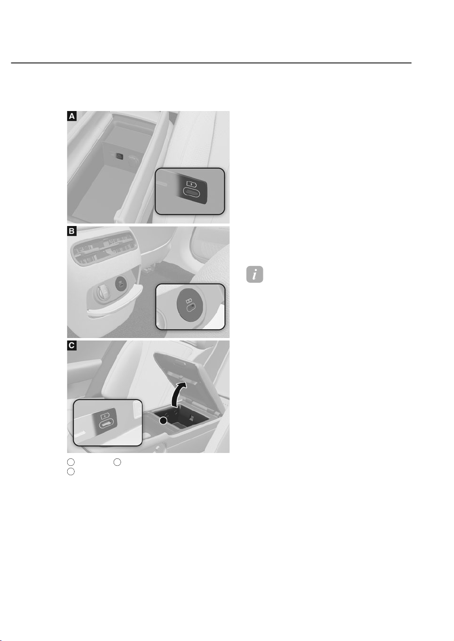
5-157
05
USB Charger (if equipped)
ORS051098
ORS051098
ORS051099
ORS051099
ORS051200
ORS051200
A
: Front seat,
B
: Rear seat (if equipped),
C
: Rear seat
The USB-C charger is designed to
recharge batteries of small size electrical
devices using a USB-C cable.
The electrical devices can be recharged
when the Engine Start/Stop button is in
the ON (or START) position.
The battery charging state may be
monitored on the electrical device.
Disconnect the USB-C cable from the
USB port after use.
• A smart phone or a tablet PC may
get warmer during the re-charging
process. It does not indicate any
malfunction with the charging system.
• A smart phone or a tablet PC, which
adopts a different re-charging
method, may not be properly re-
charged. In this case, use an exclusive
charger of your device.
• The charging terminal is only to
recharge a device. Do not use the
charging terminal either to turn on
an audio or to play media In the
infotainment system.
Information
&KDUJLQJPD\QRWEHSRVVLEOHZKHQXVLQJ
D7\SH&FRQYHUWHUVROGE\DPRELOHSKRQH
manufacturer or commercially available.
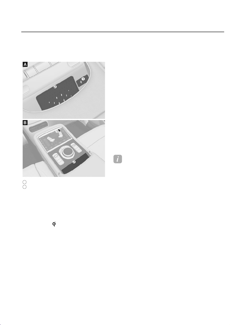
5-158
Convenience Features
Wireless Smart Phone Charging
System (if equipped)
ORS051201
ORS051201
ORS051202
ORS051202
A
: Front seat,
B
: Rear seat (if equipped),
M : Indicator light,
N : Charging pad
Charging smart phone
The wireless smart phone charging
system charges only the Qi-enabled
smart phones (
). Read the label on
the smart phone accessory cover or
visit your smart phone manufacturer’s
website to check whether your smart
phone supports the Qi technology.
The wireless charging process starts
when you put a Qi-enabled smart phone
on the wireless charging unit.
1. The system is available when all doors
are closed, and when the Engine
Start/Stop button is in the ON (or
START) position.
2. You can turn on or off the wireless
charging function from the Settings
menu. Select:
- Front seat (infotainment system):
6HWXSɌ9HKLFOHɌ&RQYHQLHQFHɌ
Wireless Charging System
- Rear seat (armrest touchscreen):
6HWXSɌ5HDU:LUHOHVV&KDUJLQJ
3. The indicator light is orange when the
smart phone is charging. The indicator
light will turn blue when phone
charging is complete.
Information
Remove other items, including the smart
key, from the wireless charging unit. If
not, the wireless charging process may be
interrupted.
If your smart phone is not charging:
• Slightly change the position of the
smart phone on the charging pad.
• Make sure the indicator light is
orange.

5-159
05
The indicator light will blink orange for 10
seconds if there is a malfunction in the
wireless charging system.
In this case, temporarily stop the
charging process, and re-attempt to
charge your smart phone again.
The system warns you with a message on
the LCD display if the smart phone is still
on the wireless charging unit after the
vehicle is turned OFF and the front door
is opened.
For some manufacturer’s smart phones,
the system may not warn you even
though the smart phone is left on the
wireless charging unit. This is due to the
particular characteristic of the smart
phone and not a malfunction of the
wireless charging.
Information
• The wireless smart phone charging
system may not support certain smart
phones, which are not verified for the
Qi specification (
).
• When placing your smart phone on the
charging pad, position the phone in the
middle of the mat for optimal charging
performance. If your smart phone is off
to the side, the charging rate may be
less and in some cases the smart phone
may experience higher heat conduction.
• In some cases, the wireless charging
may stop temporarily when the smart
key is used, either when starting the
vehicle or locking/unlocking the doors,
etc.
• When charging certain smart phones,
the charging indicator may not change
to blue when the smart phone is fully
charged.
• The wireless charging process may
temporarily stop, when temperature
abnormally increases inside the wireless
smart phone charging system. The
wireless charging process restarts,
when temperature falls to a certain
level.
• The wireless charging process may
temporarily stop when there is any
metallic item, such as a coin, between
the wireless smart phone charging
system and the smart phone.

5-160
Convenience Features
• When charging some smart phones
with a self-protection feature, the
wireless charging speed may decrease
and the wireless charging may stop.
• If the smart phone has a thick cover,
the wireless charging may not be
possible.
• If the smart phone is not completely
contacting the charging pad, wireless
charging may not operate properly.
• If the Engine Start/Stop button is in the
2))SRVLWLRQWKHFKDUJLQJDOVRVWRSV
• When any smart phone without a
wireless charging function or a metallic
REMHFWLVSODFHGRQWKHFKDUJLQJSDG
a small noise may sound. This small
sound is due to the vehicle discerning
FRPSDWLELOLW\RIWKHREMHFWSODFHGRQ
the charging pad. It does not affect
your vehicle or the smart phone in any
way.
• Some smart phones may not be able
to charge depending on the internal
structure of the smart phone. If this
occurs, try charging the mobile phone
by moving it to the left or right side of
the wireless charging pad. However, for
some foldable smart phones that have
magnets inside the smart phone, try
charging the smart phone while holding
it close to the left side of the wireless
charging pad.
NOTICE
Some magnetic items like credit cards,
phone cards or rail tickets may be
damaged if left with the smart phone
during the charging process.
Information
This device complies with Part 15 of the
)&&UXOHV
2SHUDWLRQLVVXEMHFWWRWKHIROORZLQJWKUHH
conditions:
1. This device may not cause harmful
interference, and
2. This device must accept any
interference received, including
interference that may cause undesired
operation.
3. &KDQJHVRUPRGLILFDWLRQVQRWH[SUHVVO\
approved by the party responsible
for compliance could void the user’s
authority to operate the device.
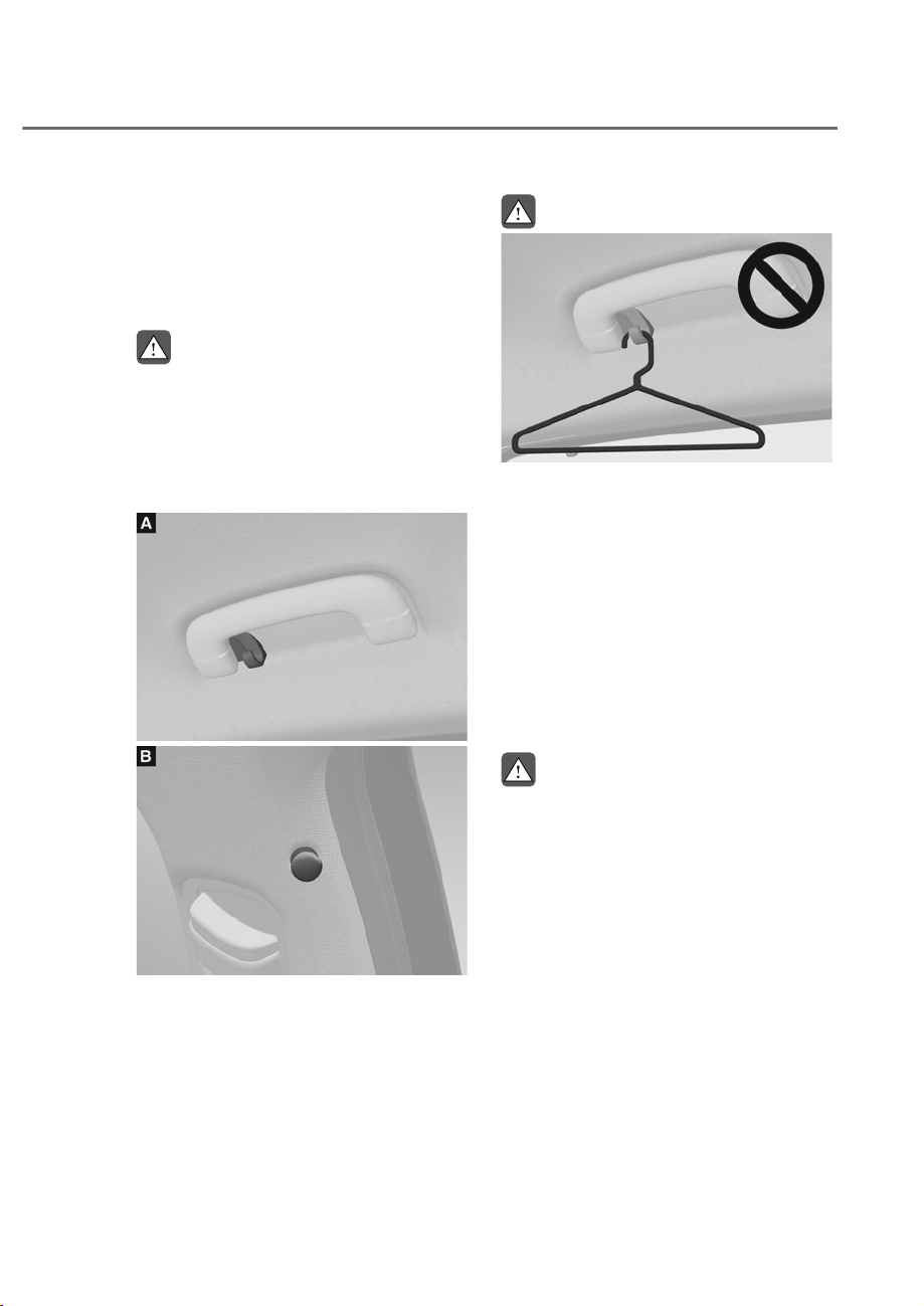
5-161
05
Clock
The clock can be set from the
infotainment system.
See additional information in supplied
Infotainment Manual.
WARNING
Do not attempt to adjust the clock
while driving. Doing so may result in
distracted driving which may lead to
an accident involving personal injury or
death.
Coat Hook
ORS051261
ORS051261
ORS051203
ORS051203
These hooks are not designed to hold
large or heavy items.
WARNING
ORS051276
ORS051276
Do not hang other objects such
as hangers or hard objects except
clothes. Also, do not put heavy, sharp
or breakable objects in the clothes
pockets. In an accident or when the
curtain air bag is inflated, it may cause
vehicle damage or personal injury.
)ORRU0DW$QFKRUV
ALWAYS use the Floor Mat Anchors to
attach the front floor mats to the vehicle.
The anchors on the front floor carpet
keep the floor mats from sliding forward.
WARNING
Do not overlay additional mats or liners
over the floor mats. If using All Weather
mats, remove the carpeted floor mats
before installing them. Only use floor
mats designed to connect to the
anchors.
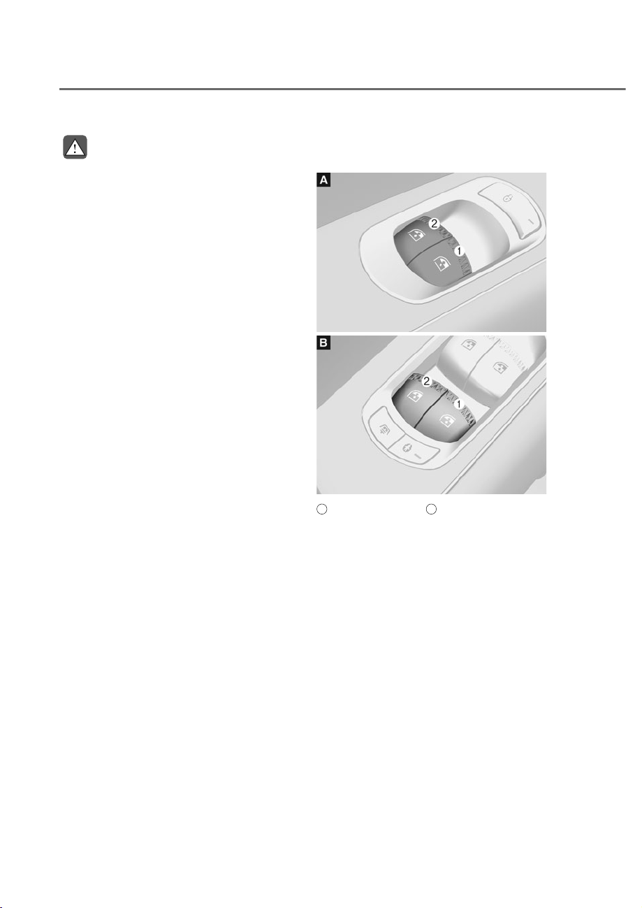
5-162
Convenience Features
WARNING
The following must be observed when
installing ANY floor mat to the vehicle.
• Ensure to remove a protective
film attached on the carpet
before attaching a floor mat on
the front floor carpet. Otherwise,
the floor mat may move freely on
the protective film and it could
result in unintentional braking or
accelerating.
• Ensure that the floor mats are
securely attached to the vehicle’s
floor mat anchor(s) before driving
the vehicle.
• Do not use ANY floor mat that cannot
be firmly attached to the vehicle’s
floor mat anchors.
• Do not stack floor mats on top of one
another (for example, all-weather
rubber mat on top of a carpeted floor
mat). Only a single floor mat should
be installed in each position.
IMPORTANT Your vehicle was
manufactured with driver’s side floor
mat anchors that are designed to
securely hold the floor mat in place.
To avoid any interference with pedal
operation, Genesis Branded Vehicle
recommends that the Genesis floor
mat designed for use in your vehicle be
installed.
Rear Side Window Sunshades (if
equipped)
ORS052204N
ORS052204N
ORS051205
ORS051205
A
: Rear window switch,
B
: Driver’s window switch
Use to block sunlight coming through the
rear windows.
Using window open/close switch
Switch M - Rear right window and sunshade
Switch N - Rear left window and sunshade
1. Pull the switch up on the driver’s or
rear seat to completely close the
window.
2. Once the window is closed, pull
the same switch again to close the
sunshades.
• To open the window when the
sunshade is closed, push down the
switch to first open the sunshade.
Then push the switch again to open
the window.
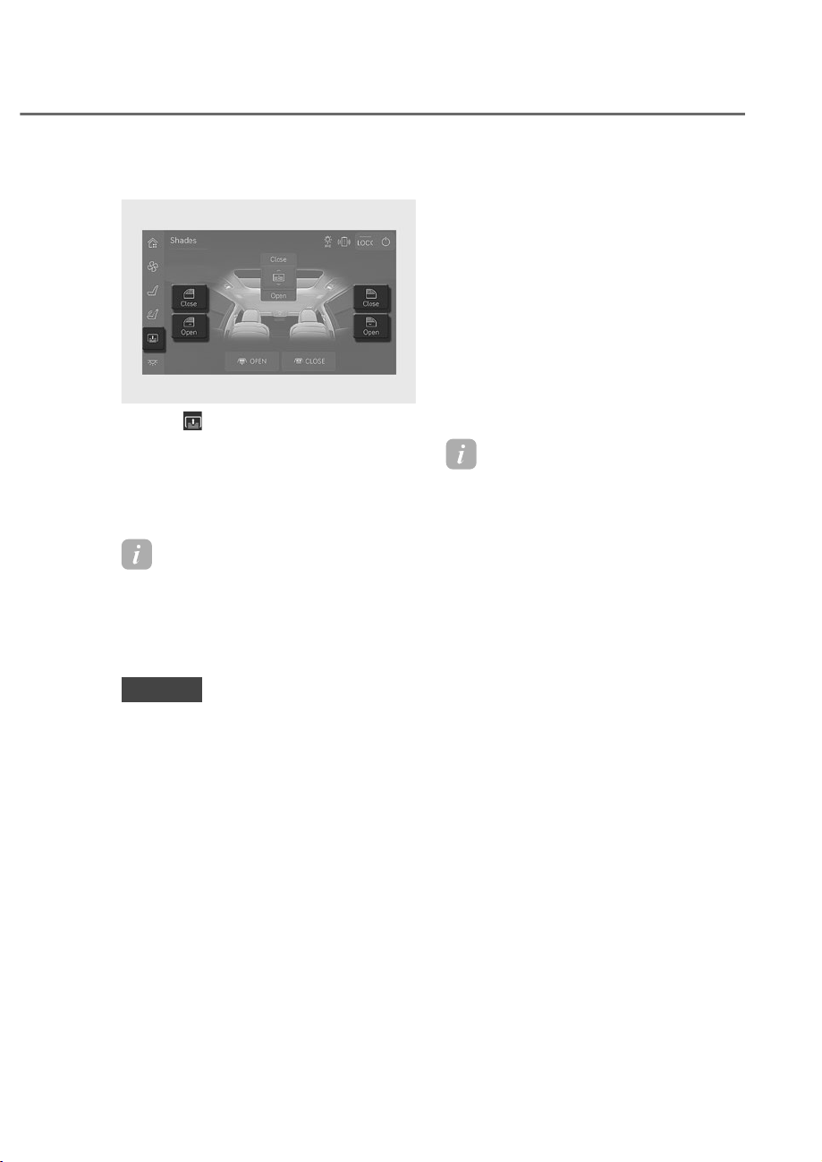
5-163
05
Using armrest touchscreen
ORS051206L
ORS051206L
1. Press from the left side menu of
armrest touchscreen.
Rear side sunshade adjustment screen
is displayed.
2. Press 'Open' or 'Close’ to open or
close the rear side window sunshades.
Information
If the operating sunshade is blocked by an
REMHFWWKHVXQVKDGHVWRSVIURPRSHQLQJ
or closing. The sunshade is only able to
open (move downward) once stopped by
obstruction.
NOTICE
Do not apply excessive external force
on the rear side window sunshade while
operating. It may cause a malfunction.
Resetting the rear side window
sunshades
If the sunshade is not operating normally,
it must be reset as follows:
1. Start the engine.
2. Continue pulling up on the power
window switch for at least 10 seconds
when the window is closed.
If the rear side window sunshade does
not work properly after following the
above procedure, have the system be
checked by an authorized retailer of
Genesis Branded products.
Information
If the temperature inside the vehicle is
EHORZ)&WKHUHDUVLGHZLQGRZ
sunshade may stop in some sections while
closing. If this occurs, operate the switch
again after raising the temperature. The
rear side window sunshades will operate
normally.

5-164
Convenience Features
Rear Window Sunshade (if
equipped)
ORS051207
ORS051207
ORS051208L
ORS051208L
Front seat (
A
)
To raise or lower the sunshade, press the
button.
Rear seat (
B
)
1. Press from the left side menu
of the armrest touchscreen. The
rear sunshade adjustment screen is
displayed.
2. Press 'Open' or 'Close to open or close
the rear window sunshade.
ORS051209
ORS051209
• The rear window sunshade will be
lowered automatically when the
vehicle is shifted to R (Reverse) and
raised automatically when the vehicle
is shifted from R (Reverse) to P (Park).
• After the rear window sunshade is
lowered by shifting the vehicle to R
(Reverse), if you drive more than 12
mph (20 km/h) with the gear in D
(Drive), the rear window sunshade will
be raised automatically.
NOTICE
• Do not apply excessive force while
operating the rear window sunshade.
This could cause damage to the rear
window sunshade.
• Do not to operate the rear window
sunshade with an object placed
on the rear seat shelf. This could
cause damage to the rear window
sunshade.
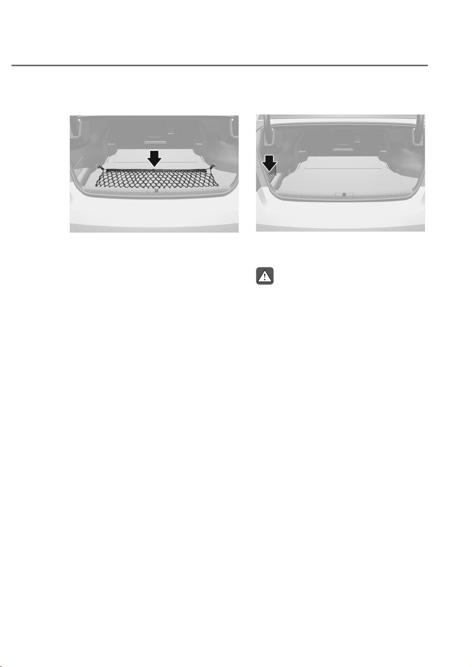
5-165
05
Luggage Net Holder
ORS051210
ORS051210
To keep items from shifting in the
luggage compartment, you can use the 4
holders located in the luggage board to
attach the luggage net.
Make sure the luggage net is securely
attached to the holders in the luggage
board.
If necessary, contact your authorized
retailer of Genesis Branded products to
obtain a luggage net.
Side luggage net
ORS051211
ORS051211
Use the side luggage net to store small
items in the luggage compartment.
WARNING
Avoid eye injury. DO NOT overstretch
the luggage net. ALWAYS keep your
face and body out of the luggage net’s
recoil path. DO NOT use the luggage net
when the strap has visible signs of wear
or damage.
Use the luggage net to keep only light
items from shifting in the luggage
compartment.
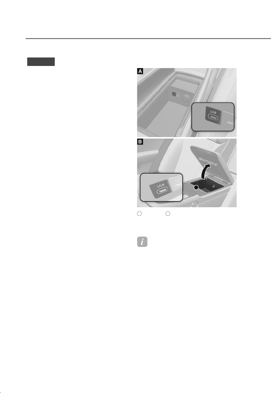
5-166
Convenience Features
,1)27$,10(176<67(0
NOTICE
• If you install an aftermarket HID
head lamp, your vehicle’s audio and
electronic devices may not function
properly.
• Prevent chemicals such as perfume,
cosmetic oil, sun cream, hand
cleaner, and air freshener from
contacting the interior parts
because they may cause damage or
discoloration.
USB-C Port
ORS051217
ORS051217
ORS051218
ORS051218
A
: Front seat,
B
: Rear seat
You can use an USB-C cable to connect
audio devices to the vehicle USB-C port.
Information
When using a portable audio device
connected to the power outlet, noise may
occur during playback. If this happens,
use the portable audio device’s power
source.
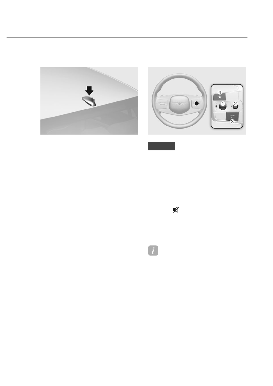
5-167
05
Antenna
ORS051212
ORS051212
The shark fin antenna will receive AM,
FM broadcast signals and transmit data.
Steering Wheel Remote Controls
ORS051213
ORS051213
NOTICE
Do not operate multiple audio remote
control buttons simultaneously.
(1) Volume (+/-)
• Push the Volume scroll up to increase
volume.
• Push the Volume scroll down to
decrease volume.
Mute ( )
• Press the Mute button to mute the
sound.
• Press the Mute button again to
activate the sound.
Information
You can set the volume level of each
source (FM, AM, SXM, USB, BT, etc.)
LQGLYLGXDOO\E\DGMXVWLQJWKH92/80(
scroll.
Then the infotainment system saves the
last volume level of each source in the
system sound settings.
If you change the source, the volume will
revert to the previously set volume for that
source.
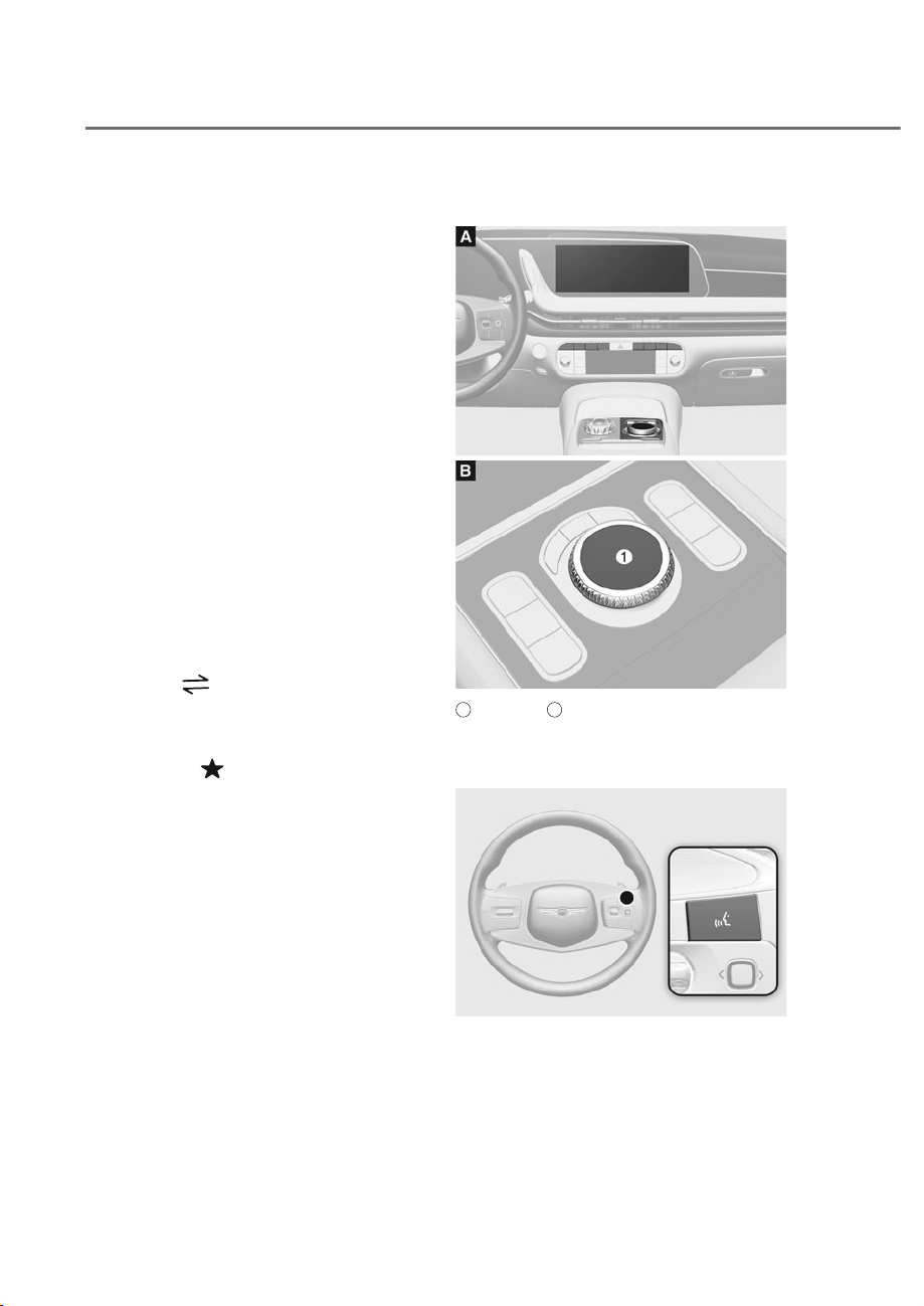
5-168
Convenience Features
(2) SEEK/PRESET (< / >)
If the SEEK/PRESET switch (optical
mouse) is swiped to the left or right
and held for 0.8 second or more, it will
function in the following modes:
•
Radio mode
It will function as the AUTO SEEK
select button. It will SEEK until you
release the button.
•
Media mode
It will function as the FF/RW button.
If the SEEK/PRESET switch (optical
mouse) is swiped to the left or right , it
will function in the following modes:
•
Radio mode
It will function by moving between
stored PRESET STATIONS
•
Media mode
It will function as the TRACK UP/
DOWN button.
(3) Mode ( )
Press the MODE button to toggle
through the Radio mode or Media mode.
(4) Custom ( )
Press the Custom button to set
frequently used features.
Infotainment System
ORS051214
ORS051214
ORS052325N
ORS052325N
A
: Front seat,
B
: Rear seat (if equipped)
M: Infotainment system controller
Voice Recognition
ORS051221
ORS051221
See additional information in supplied
Infotainment Manual.
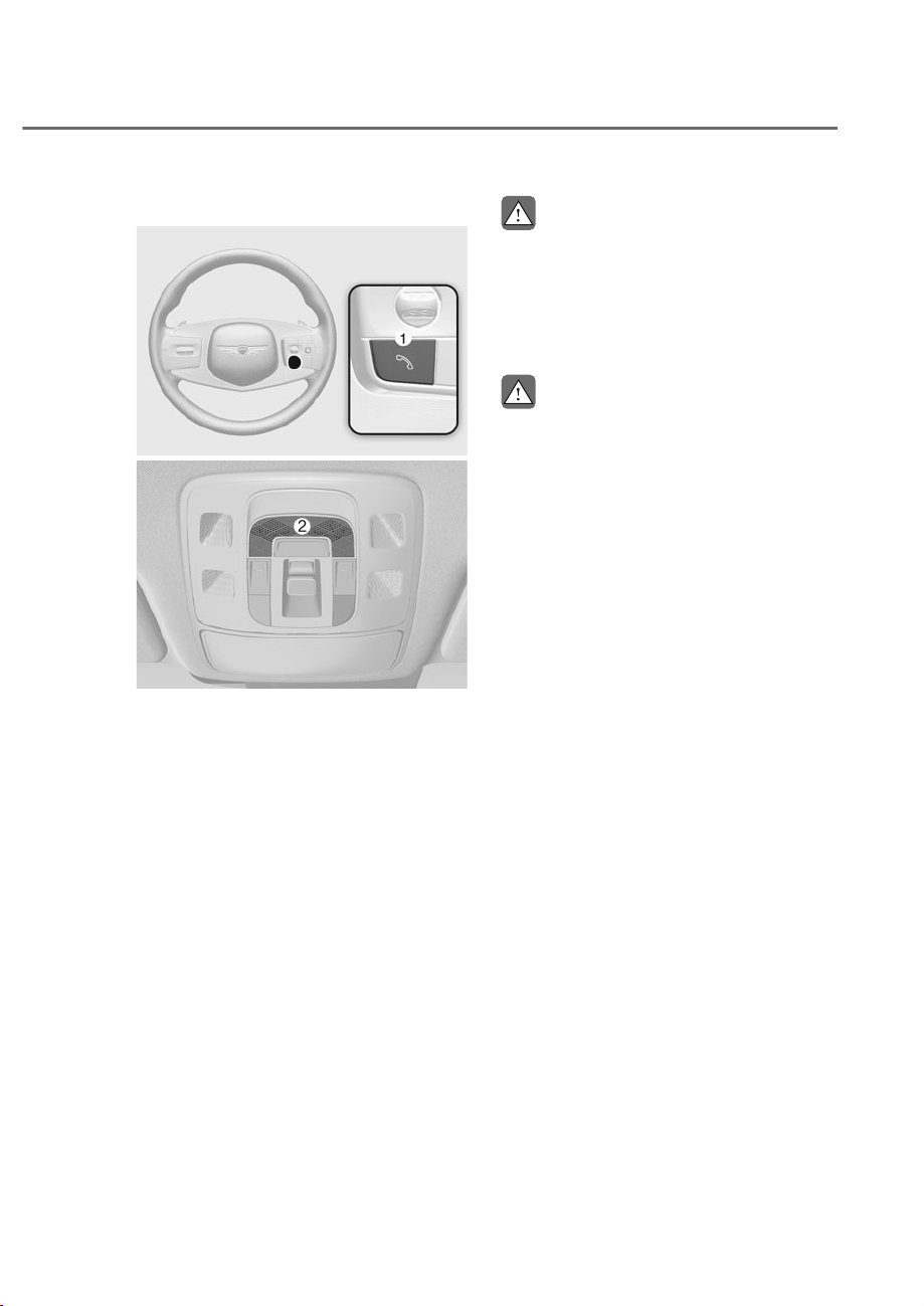
5-169
05
%OXHWRRWKp:LUHOHVV7HFKQRORJ\
ORS051219
ORS051219
ORS052220N
ORS052220N
M : Call / Answer / Call end button
N
: Microphone
See additional information in supplied
Infotainment Manual.
CAUTION
To avoid driver distractions, do not
excessively operate the device while
driving the vehicle which may lead to
an accident.
%$1*2/8)6(1VRXQGV\VWHP
CAUTION
%$1*2/8)6(1VRXQGV\VWHPLV
equipped with door speaker grills made
of stainless steel. The grill surface can
be heated when the vehicle is exposed
to hot weather for a long period of time.
Keep away from the speaker grill when
it is hot.

6
Before Driving ................................................................................................... 6-4
Before Entering the Vehicle .........................................................................................6-4
Before Starting
.............................................................................................................6-4
Engine Start/Stop Button ................................................................................. 6-5
Engine Stop/Start Button Positions ............................................................................6-6
Starting the Engine
......................................................................................................6-7
Turning Off the Engine
.................................................................................................6-8
Remote Starting
...........................................................................................................6-9
Vehicle Auto-Shut Off .....................................................................................6-10
Operating Conditions ............................................................................................... 6-10
Deactivating Conditions
.......................................................................................... 6-10
System Operation
...................................................................................................... 6-10
Automatic Transmission .................................................................................6-11
Automatic Transmission Operation .......................................................................... 6-11
LCD Display Messages (Cluster)
............................................................................... 6-17
Paddle Shifter (Manual Shift Mode)
......................................................................... 6-21
Good Driving Practices
............................................................................................. 6-21
Braking System ...............................................................................................6-23
Power-Assist Brakes .................................................................................................. 6-23
Disc Brakes Wear Indicator....................................................................................... 6-23
Electronic Parking Brake (EPB)
................................................................................. 6-24
Auto Hold
................................................................................................................... 6-28
Anti-Lock Brake System (ABS)
.................................................................................. 6-31
Electronic Stability Control (ESC)
............................................................................ 6-33
Vehicle Stability Management (VSM)
...................................................................... 6-35
Hill-Start Assist Control (HAC)
.................................................................................. 6-37
Brake Assistant System (BAS)
................................................................................... 6-37
Good Braking Practices
............................................................................................ 6-38
All Wheel Drive (AWD) ...................................................................................6-39
All Wheel Drive (AWD) Operation ............................................................................. 6-40
Emergency Precautions
............................................................................................ 6-41
Electronically Controlled Suspension with Road Preview ...........................6-43
System Malfunction .................................................................................................. 6-44
Limitations of the System
......................................................................................... 6-44
Multi-chamber Air Suspension ......................................................................6-45
Vehicle Height Adjustment ...................................................................................... 6-45
Multi-Chamber Air Suspension Malfunction
........................................................... 6-46
Additional Height Adjustment Function
.................................................................. 6-47
Towing When the Air Suspension Malfunction
...................................................... 6-48
6. Driving Your Vehicle

6
Idle Stop and Go (ISG) ...................................................................................6-49
ISG System Operation ............................................................................................... 6-49
ISG System Off........................................................................................................... 6-51
Forced to Restart Engine
.......................................................................................... 6-52
ISG Malfunction
......................................................................................................... 6-52
Calibrating the Battery Sensor
................................................................................. 6-53
Coasting ..........................................................................................................6-54
Coasting Setting ........................................................................................................ 6-54
Coasting Operating Conditions
................................................................................ 6-54
Coasting Release Conditions
................................................................................... 6-55
Predictive Shift ................................................................................................6-56
Predictive shift Operating Conditions ..................................................................... 6-56
Predictive shift off Conditions
................................................................................. 6-56
Limitations of the System
........................................................................................ 6-57
Checking Operation on the Instrument Cluster
...................................................... 6-57
How Predictive Shift Operates
................................................................................. 6-59
Drive Mode Integrated Control System .........................................................6-61
Selecting Drive Mode ................................................................................................ 6-61
ECO, COMFORT, SPORT Mode Features
................................................................. 6-62
CUSTOM Mode Features .......................................................................................... 6-63
Road Active Noise Control .............................................................................6-65
System Malfunction .................................................................................................. 6-65
Active Sound Design.......................................................................................6-65
Special Driving Conditions
............................................................................. 6-66
Hazardous Driving Conditions ................................................................................. 6-66
Rocking the Vehicle
.................................................................................................. 6-66
Smooth Cornering
..................................................................................................... 6-67
Driving at Night
......................................................................................................... 6-67
Driving in the Rain
..................................................................................................... 6-68
Driving in Flooded Areas
........................................................................................... 6-68
Highway Driving
........................................................................................................ 6-68
Winter Driving .................................................................................................6-69
Snow or Icy Conditions ............................................................................................. 6-69
Winter Precautions
.................................................................................................... 6-73
Vehicle Load Limit ..........................................................................................6-75
The Loading Information Label ................................................................................ 6-75
Trailer Towing ..................................................................................................6-79

6-3
06
WARNING
Carbon monoxide (CO) gas is toxic. Breathing CO can cause unconsciousness and
death.
Engine exhaust contains carbon monoxide which cannot be seen or smelled.
Do not inhale engine exhaust.
If at any time you smell engine exhaust inside the vehicle, open the windows
immediately. Exposure to CO can cause unconsciousness and death by asphyxiation.
Be sure the exhaust system does not leak.
The exhaust system should be checked whenever the vehicle is raised to change the
oil or for any other purpose. If you hear a change in the sound of the exhaust or if you
drive over something that strikes the underneath side of the vehicle, have the exhaust
system checked as soon as possible by an authorized retailer of Genesis Branded
products.
Do not run the engine in an enclosed area.
Letting the engine idle in your garage, even with the garage door open, is a hazardous
practice. Run the engine only long enough to start the engine and to move the vehicle
out of the garage.
Avoid idling the engine for prolonged periods with people inside the vehicle.
If it is necessary to idle the engine for a prolonged period with people inside the
vehicle, be sure to do so only in an open area with the air intake set at “Fresh” and fan
control set to high so fresh air is drawn into the interior.
Keep the air intakes clear.
To assure proper operation of the ventilation system, keep the ventilation air intakes
located in front of the windshield clear of snow, ice, leaves, or other obstructions.
If you must drive with the trunk open:
Close all windows.
Open instrument panel air vents.
Set the air intake control at “Fresh”, the air flow control at “Floor” or “Face”, and the fan
control set to high.
WARNING
CALIFORNIA PROPOSITION 65 WARNING
Engine exhaust and a wide variety of automobile components including
components found in the interior furnishings in a vehicle, contain or emit harmful
chemicals known to the State of California to cause cancer and birth defects and
reproductive harm. In addition, certain fluids contained in vehicles and certain
products of components contain or emit chemicals known to the State of California
to cause cancer and birth defects or other reproductive harm.

6-4
Driving Your Vehicle
Before Entering the Vehicle
ȉ Be sure all windows, side view
mirror(s), and outside lights are clean
and unobstructed.
ȉ Remove frost, snow, or ice.
ȉ Visually check the tires for uneven
wear and damage.
ȉ Check under the vehicle for any sign
of leaks.
ȉ Be sure there are no obstacles behind
you if you intend to back up.
Before Starting
ȉ Make sure the hood, the trunk, and
the doors are securely closed and
locked.
ȉ Adjust the position of the seat and
steering wheel.
ȉ Adjust the inside and outside rearview
mirrors.
ȉ Verify all the lights work.
ȉ Fasten your seat belt. Check that all
passengers have fastened their seat
belts.
ȉ Check the gauges and indicators
in the instrument panel and the
messages on the instrument display
when the Engine Start/Stop button is
in the ON position.
ȉ Check that any items you are carrying
are stored properly or fastened down
securely.
WARNING
To reduce the risk of SERIOUS INJURY or
DEATH, take the following precautions:
ȉ ALWAYS wear your seat belt. All
passengers must be properly belted
whenever the vehicle is moving.
For more information, refer to “Seat
Belts” section in chapter 3.
ȉ Always drive defensively. Assume
other drivers or pedestrians may be
careless and make mistakes.
ȉ Stay focused on the task of driving.
Driver distraction can cause
accidents.
ȉ Leave plenty of space between you
and the vehicle in front of you.
WARNING
NEVER drink or take drugs and drive.
Drinking or taking drugs and driving
is dangerous and may result in an
accident and SERIOUS INJURY or
DEATH.
Drunk driving is the number one
contributor to the highway death
toll each year. Even a small amount
of alcohol will affect your reflexes,
perceptions and judgment. Just
one drink can reduce your ability to
respond to changing conditions and
emergencies and your reaction time
gets worse with each additional drink.
Driving while under the influence
of drugs is as dangerous as or more
dangerous than driving under the
influence of alcohol.
You are much more likely to have a
serious accident if you drink or take
drugs and drive. If you are drinking or
taking drugs, don’t drive. Do not ride
with a driver who has been drinking
or taking drugs. Choose a designated
driver or call a taxi.
BEFORE DRIVING
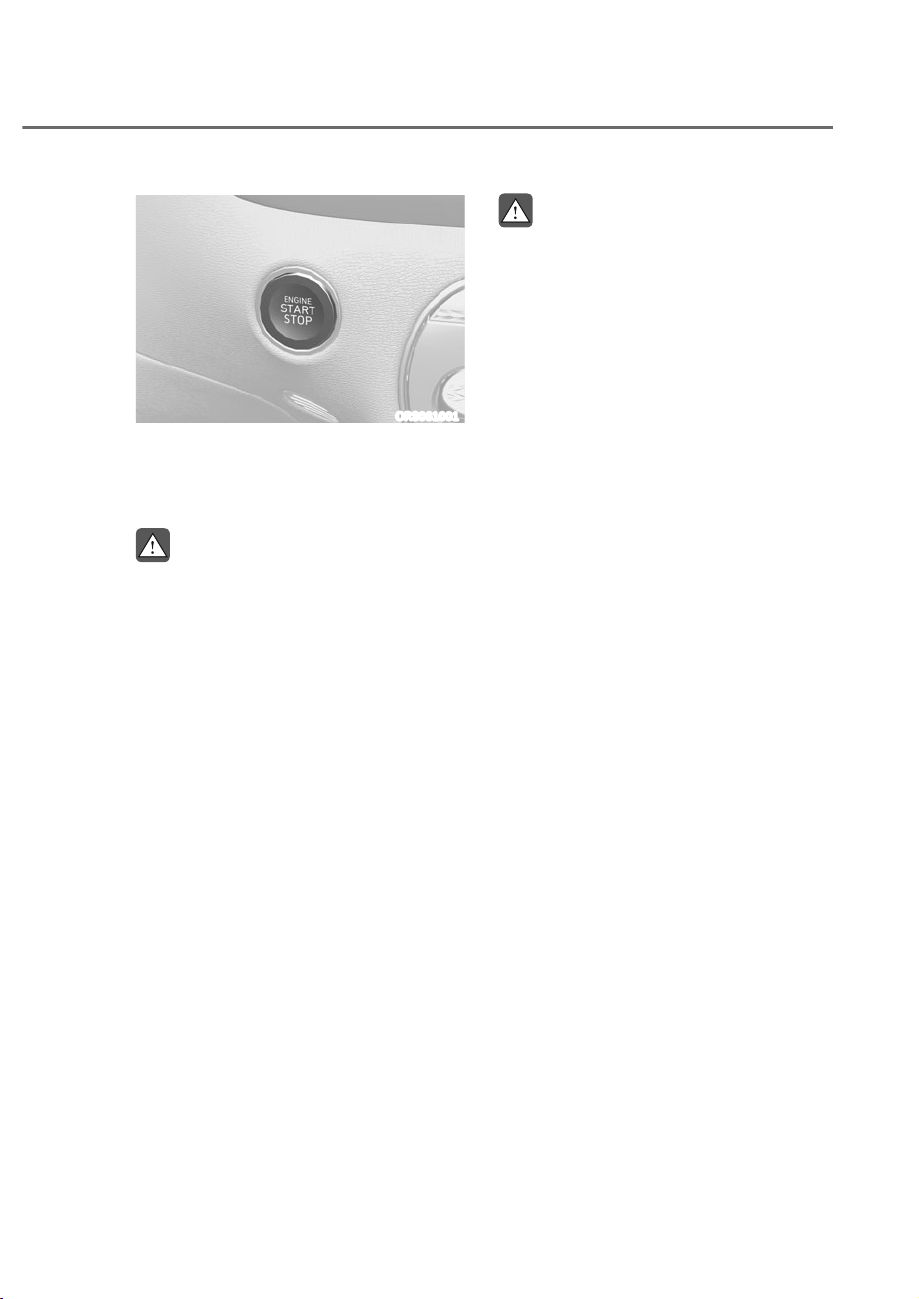
6-5
06
ORS061001
Whenever the front door is opened, the
Engine Start/Stop button will illuminate
and will go off 30 seconds after the door
is closed.
WARNING
To turn the vehicle off in an emergency:
Press and hold the Engine Start/Stop
button for more than two seconds OR
Rapidly press and release the Engine
Start/ Stop button three times (within
three seconds).
If the vehicle is still moving, you can
restart the vehicle without depressing
the brake pedal by pressing the Engine
Start/Stop button with the gear in the N
(Neutral) position.
WARNING
ȉ NEVER press the Engine Start/Stop
button while the vehicle is in motion
except in an emergency. This will
result in the vehicle turning off and
loss of power assist for the steering
and brake systems. This may lead
to loss of directional control and
braking function, which could cause
an accident.
ȉ Before leaving the driver’s seat,
always make sure the gear is in the
P (Park) position, set the parking
brake, press the Engine Start/Stop
button to the OFF position, and take
the Smart Key with you. Unexpected
vehicle movement may occur if these
precautions are not followed.
ȉ NEVER reach through the steering
wheel for the Engine Start/Stop
button or any other control while the
vehicle is in motion. The presence
of your hand or arm in this area
may cause a loss of vehicle control
resulting in an accident.
ENGINE START/STOP BUTTON

6-6
Driving Your Vehicle
Engine Stop/Start Button Positions
Button Position Action Notes
OFF
To turn off the engine, press the
Engine Start/Stop button with the
vehicle shifted to P (Park).
If the Engine Start/Stop button is
pressed with the vehicle shifted
to D (Drive), R (Reverse), or N
(Neutral), the gear automatically
shifts to P (Park).
ACC
Press the Engine Start/Stop button
when the button is in the OFF
position without depressing the
brake pedal.
Some of the electrical accessories
are usable.
If you leave the Engine Start/Stop
button in the ACC position for
more than one hour, the battery
power will turn off automatically
to prevent the battery from
discharging.
ON
Press the Engine Start/Stop button
while it is in the ACC position
without depressing the brake
pedal.
The warning lights can be checked
before the engine is started.
Do not leave the Engine Start/Stop
button in the ON position when the
engine is not running to prevent
the battery from discharging.
START
To start the engine, depress the
brake pedal and press the Engine
Start/ Stop button with the gear
shifted to the P (Park) or the N
(Neutral) position.
For your safety, start the engine
with the gear shifted to the P
(Park) position.
If you press the Engine Start/Stop
button without depressing the
brake pedal, the engine does not
start and the Engine Start/Stop
button changes as follows:
2))Ɍ$&&Ɍ21Ɍ2))RU$&&
à To prevent vehicle battery discharge, the Engine Start/Stop button changes to the
OFF position when the Engine Start/Stop button is in the ACC or ON position with
the gear in P (Park) for a certain period of time. When the function operates, the tail
lamps will turn off. To use the tail lamps again, turn the headlight switch located on
the steering column to the OFF and ON position again.

6-7
06
Starting the Engine
WARNING
ȉ Always wear appropriate shoes when
operating your vehicle. Unsuitable
shoes, such as high heels, ski boots,
sandals, flip flops, etc., may interfere
with your ability to use the brake and
accelerator pedals.
ȉ Do not start the vehicle with the
accelerator pedal depressed.
The vehicle can move which can lead
to an accident.
ȉ Wait until the engine RPM is normal.
The vehicle may suddenly move if
the brake pedal is released when the
RPM is high.
Information
ȉ The vehicle will start by pressing the
Engine Start/Stop button, only when
the smart key is in the vehicle.
ȉ Even if the smart key is in the vehicle,
and when it is far away from the driver,
the engine may not start.
ȉ When the Engine Start/Stop button
is in the A or N position, if any
door is open, the system checks for the
smart key. When the smart key is not
in the vehicle, the “
” indicator
will blink and the warning 'Key not in
vehicle' will come on. When all doors
are closed, the chime will also sound for
about 5 seconds. Keep the smart key in
the vehicle.
1. Always carry the smart key with you.
2. Make sure the parking brake is
applied.
3. Make sure the gear is shifted to P
(Park) or N(Neutral).
4. Depress the brake pedal.
5. Press the Engine Start/Stop button.
Information
ȉ Do not wait for the engine to warm up
while the vehicle remains stationary.
Start driving at moderate engine
speeds. Steep accelerating and
decelerating should be avoided.
ȉ Always start the vehicle with your foot
on the brake pedal. Do not depress the
accelerator while starting the vehicle.
Do not race the engine while warming
it up.

6-8
Driving Your Vehicle
NOTICE
To prevent damage to the vehicle:
ȉ If the engine stalls while you are in
motion, do not attempt to shift the
gear to the P (Park) position.
If traffic and road conditions permit,
you may put the gear in N (Neutral)
while the vehicle is still moving and
press the Engine Start/Stop button in
an attempt to restart the engine.
ȉ Do not push or tow your vehicle to
start the vehicle.
NOTICE
To prevent damage to the vehicle:
Do not press the Engine Start/Stop
button for more than 10 seconds except
when the stop lamp fuse is blown.
When the stop lamp fuse is blown,
you cannot normally start the engine.
Replace the fuse with a new one. If you
are not able to replace the fuse, you
can start the engine by pressing and
holding the Engine Start/Stop button
for 10 seconds with the Engine Start/
Stop button in the ACC position.
For your safety always depress the
brake pedal before starting the vehicle.
Emergency starting
ORS061016L
If the smart key battery is weak or the
smart key does not work correctly, you
can start the vehicle by pressing the
Engine Start/Stop button with the smart
key in the direction of the picture above.
Turning Off the Engine
1. Stop the vehicle and depress the
brake pedal fully.
2. Press the P button to shift to P (Park).
3. Press the Engine Start/Stop button
to the OFF position and apply the
parking brake.
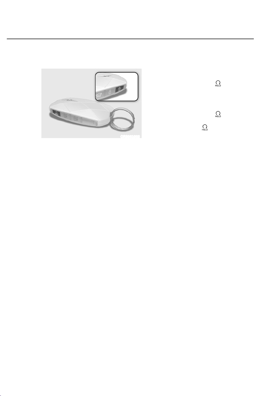
6-9
06
Remote Starting
ORS061002
You can start the vehicle using the
Remote Start button of the smart key.
To start the vehicle remotely:
1. Press the door lock button within
32 ft. (10 m) from the vehicle.
2. Press the remote start (
) button for
over 2 seconds within 4 seconds after
locking the doors. The hazard warning
lights will blink.
3. To turn off the remote start function,
press the remote start (
) button
once.
ȉ The remote start (
) button may not
operate if the smart key is not within
32 ft. (10 m).
ȉ The vehicle will not remotely start if
the engine hood or trunk is opened.
ȉ The vehicle must be in P (Park) for the
remote start function to start.
ȉ The engine turns off if you get in the
vehicle without a registered smart key.
ȉ The engine turns off if you do not get
in the vehicle within 10 minutes after
remotely starting the vehicle.
ȉ Do not idle the engine for a long
period.
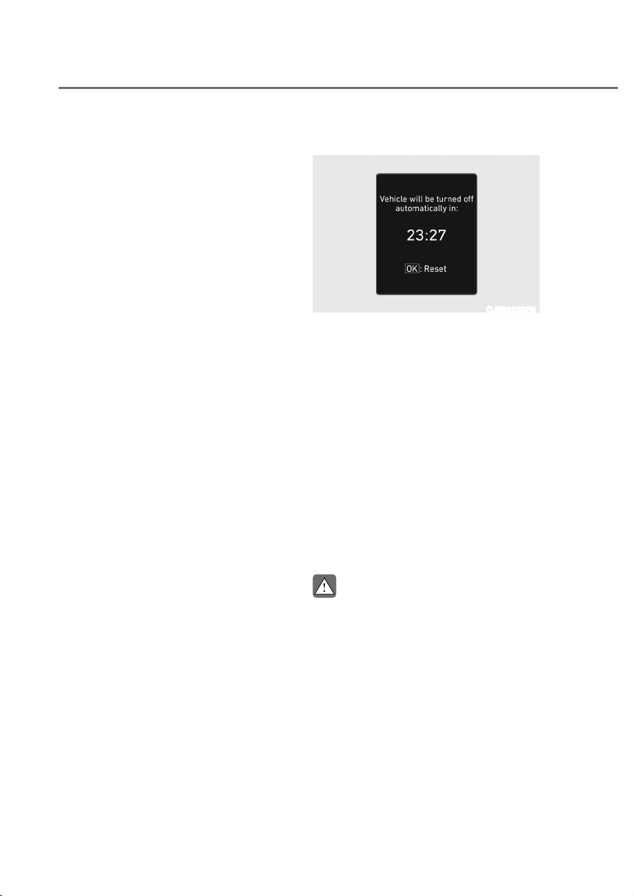
6-10
Driving Your Vehicle
9(+,&/($872ʏ6+872))
If your vehicle is parked and the engine
is left on for a long period of time, the
engine will turn off automatically to help
reduce fuel consumption and prevent
accidents caused by carbon dioxide
poisoning.
Operating Conditions
Vehicle Auto-Shut Off timer operates
when all the following conditions are
satisfied:
ȉ Vehicle speed is below 1.8 mph (3
km/h), and the gear is shifted to P
(Park)
ȉ The brake pedal and accelerator pedal
are not depressed
ȉ The driver’s seat belt is unfastened
ȉ The passenger seat is empty
ȉ The infotainment system is not being
updated
Deactivating Conditions
Vehicle Auto-Shut Off timer turns off
when one of the situation occur:
ȉ Vehicle speed is above 1.8 mph (3
km/h)
ȉ The gear is shifted to R (Reverse), D
(Drive) or N (Neutral)
ȉ The brake pedal or accelerator pedal
is depressed
ȉ The driver’s seat belt is fastened
ȉ A passenger is in the passenger’s seat
System Operation
OJK041087N
When all the conditions are satisfied, the
Vehicle Auto-Shut Off operates and turns
the engine off automatically after 60
minutes.
A timer appears on the instrument
cluster 30 minutes before vehicle shut
off.
Resetting cluster timer
To reset the cluster timer, do one of
following:
ȉ Release the accelerator pedal or brake
pedal after Vehicle Auto-Shut Off is
complete.
ȉ Press the OK button on the steering
wheel while the timer appears on the
instrument cluster.
CAUTION
Do not leave a passenger or a pet in
the vehicle in hot weather since the air
conditioning system turns off when the
engine is off.
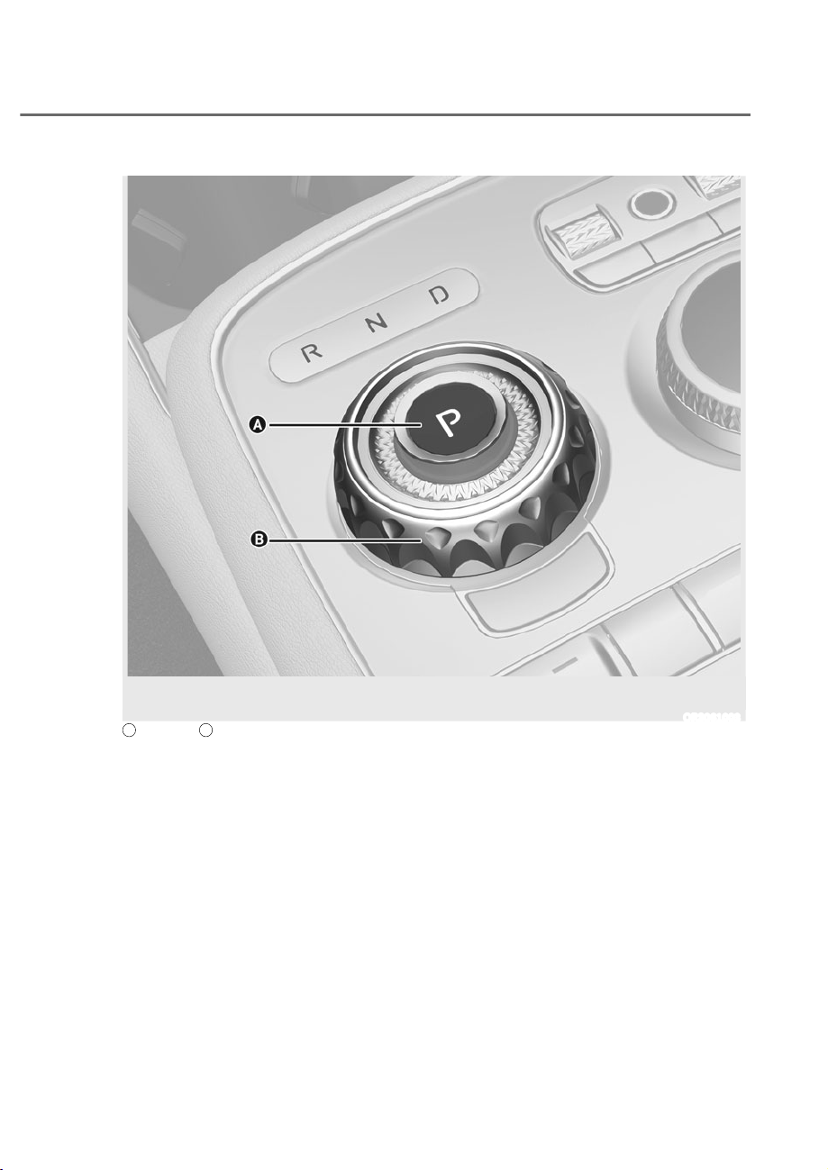
6-11
06
Depress the brake pedal whenever rotating the shift dial to change gear or shifting P.
ORS061003
A
: P button,
B
: Rotary shifter (Rotary gear shift dial)
Automatic Transmission Operation
The automatic transmission has eight forward speeds and one reverse speed.
The individual speeds are selected automatically in the D (Drive) position.
AUTOMATIC TRANSMISSION
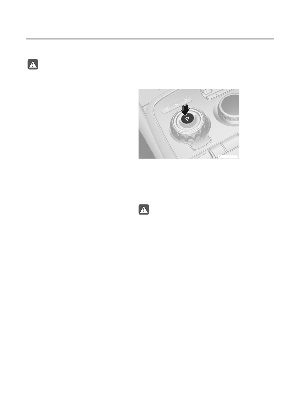
6-12
Driving Your Vehicle
WARNING
To reduce the risk of serious injury or
death:
ȉ ALWAYS check the surrounding
areas near your vehicle for people,
especially children, before shifting a
vehicle into D (Drive) or R (Reverse).
ȉ Before leaving the driver's seat,
always make sure the vehicle is
shifted to the P (Park) position, then
apply the parking brake, then press
the Engine Start/Stop button to
the OFF position. Unexpected and
sudden vehicle movement can occur
if these precautions are not followed.
ȉ When using the paddle shifter
(manual shift mode), do not use
engine braking (shifting from a
high gear to lower gear) rapidly on
slippery roads. The vehicle may slip
causing an accident.
Rotary shifter/ Rotary gear shift dial
P (Park)
Always come to a complete stop before
shifting into P (Park).
ORS061004
To shift the gear to R (Reverse), press
the P button while depressing the brake
pedal.
If you turn the engine off in R (Reverse),
N (Neutral) or D (Drive), the gear will
automatically shift to P (Park).
WARNING
ȉ Shifting into P (Park) while the
vehicle is in motion may cause you to
lose control of the vehicle.
ȉ After the vehicle has stopped, always
make sure the vehicle is in P (Park),
apply the parking brake, and turn the
engine off.
ȉ When parking on an incline, shift
the gear to P (Park) and apply the
parking brake to prevent the vehicle
from rolling downhill.
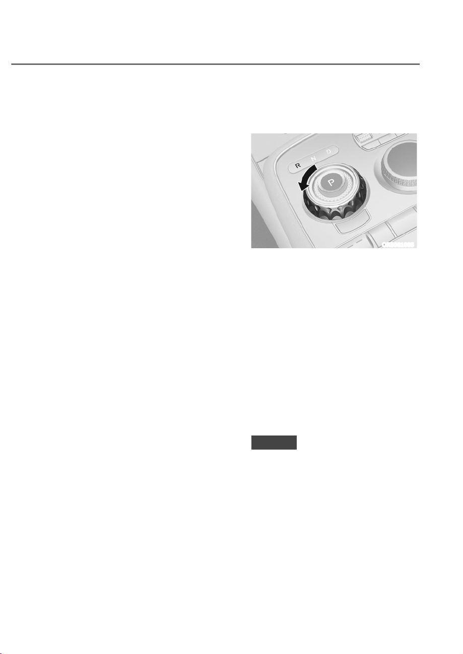
6-13
06
Automatic gear shift to P (Park)
The gear is shifted to P (Park)
automatically for safety reasons under
the following conditions:
- When the engine is turned off with
the gear in R (Reverse), D (Drive) or N
(Neutral).
- When the driver’s door is opened
with the engine running, the gear in R
(Reverse), D (Drive) or N (Neutral), the
seat belt unfastened and the vehicle
at a standstill.
- When the driver’s or front passenger’s
door is opened with the gear in N
(Neutral) and the vehicle is turned off.
In situations in which the gear must
be in P (Park), always check if the gear
is shifted to P (Park) by checking the
cluster.
R (Reverse)
Use this position to drive the vehicle
rearward.
ORS061005
To shift the gear to R (Reverse), rotate
the shift dial counterclockwise while
depressing the brake pedal.
The dial will vibrate each time it is
shifted to R (Reverse). It is to prevent
incorrect dial shift or to notify the
driver the dialshift is in the R (Reverse)
position.
When the vehicle is stopped in the
R (Reverse) position, if you open
the driver's door with the seat belt
unfastened, the gear will automatically
shift to P (Park).
However, if the vehicle is in motion, the
gear may not automatically shift to P
(Park) to prevent automatic transmission
damage.
NOTICE
Always come to a complete stop before
shifting into or out of R (Reverse); you
may damage the transmission if you
shift into R (Reverse) while the vehicle is
in motion.
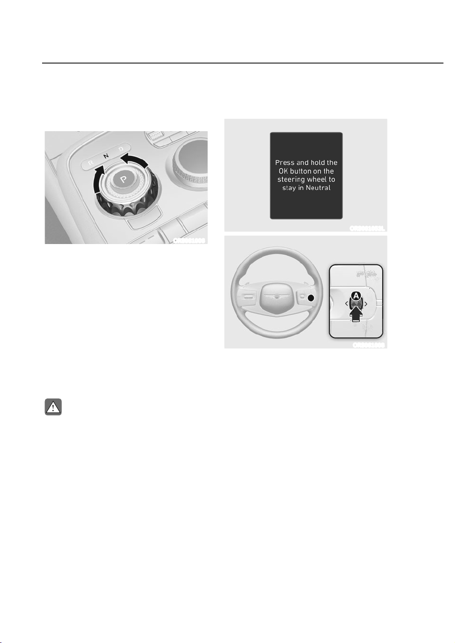
6-14
Driving Your Vehicle
N (Neutral)
The wheels and transmission are not
engaged.
ORS061006
To shift the gear to N (Neutral), rotate the
shift dial clockwise from R (Reverse) or
counterclockwise from D (Drive) while
depressing the brake pedal.
Always depress the brake pedal when
you are shifting from N (Neutral) to
another gear.
If you turn the engine off in N (Neutral),
the gear will automatically shift to P
(Park).
However, if you need to stay in N
(Neutral) with the engine off, refer to “To
stay in N (Neutral) when vehicle is OFF”
in the following page.
CAUTION
The engine can be started with the gear
in N (Neutral), but for you safety, be
sure to start the engine with the gear in
P (Park).
To stay in N (Neutral) when vehicle is
OFF
ORS061052L
ORS061008
If you want to stay in N (Neutral) after the
engine is OFF (in the ACC state), do the
following.
1. Turn off Auto Hold and release
Electronic Parking Brake when the
engine is running.
2. Rotate the shift dial to N (neutral)
while depressing the brake pedal.
3. When you take your foot off the brake
pedal, the message ‘Press and hold
OK button to stay in Neutral when
vehicle is Off’ will appear on the
cluster LCD display.
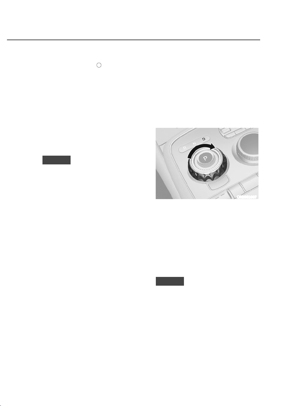
6-15
06
4. Press and hold the
A
button on
the steering wheel for more than 1
second.
5. When the message ‘Vehicle will stay in
(N). Change gear to cancel’ (or ‘N will
stay engaged when the vehicle is Off’)
will appear on the cluster LCD display,
press the Engine Start/Stop button
while depressing the brake pedal.
However, if you open the driver and
front passenger’s door, the gear will
automatically shift to P (Park) and the
Engine Start/Stop button will change
to the OFF position.
NOTICE
With the gear in N (Neutral) the Engine
Start/Stop button will be in the ACC
position. In the ACC position, the doors
cannot be locked. The battery may
discharge if left in the ACC position for
a long time.
D (Drive)
This is the normal driving position.
The transmission will automatically shift
through an 8-gear sequence, providing
the best fuel economy and power.
For extra power when passing another
vehicle or driving uphill, depress the
accelerator pedal further until you feel
the transmission downshift to a lower
gear.
ORS061007
To shift the gear to D (Drive), rotate the
shift dial clockwise while depressing the
brake pedal.
When the vehicle is stopped in the D
(Drive) position, if you open the driver's
door with the seat belt unfastened, the
gear will automatically shift to P (Park).
However, if the vehicle is in motion, the
gear may not automatically shift to P
(Park) to prevent automatic transmission
damage.
NOTICE
Always come to a complete stop before
shifting into D (Drive).

6-16
Driving Your Vehicle
CAUTION
When you start after stopping on a
steep incline, even if the gear is in
D (Drive), if you do not depress the
accelerator or brake pedal, the vehicle
may roll backwards, which can cause an
accident.
When the battery is discharged
You cannot shift gears, when the battery
is discharged.
In emergencies, do the following to shift
the gear to N (Neutral) on a level ground.
1. Connect the battery cables from
another vehicle or from another
battery to the jump-starting terminals
inside the engine compartment.
For more details, refer to "Jump
Starting" section in chapter 8.
2. Release the Electronic Parking Brake
with the Engine Start/Stop button in
the ON position.
3. Shift the gear to the N (Neutral)
position. Refer to the “To stay in N
(Neutral) when vehicle is OFF” in this
chapter.
Information
In situations when the gear needs to be
shifted from P (Park) to N (Neutral) when
the Engine Start/Stop button is in the
FF position, refer to the “To stay in N
(Neutral) when vehicle is FF” in this
chapter.
Shift-lock system
For your safety, the automatic
transmission has a shift-lock system
which prevents shifting the transmission
from P (Park) into R (Reverse) or D (Drive)
unless the brake pedal is depressed.
To shift from P (Park) or N (Neutral) into R
(Reverse) or D (Drive):
1. Depress and hold the brake pedal.
2. Start the engine.
3. Shift gear while depressing the brake
pedal.
Parking
Always come to a complete stop and
continue to depress the brake pedal.
Shift the gear to P (Park), apply the
parking brake, and press the Engine
Start/Stop button to the OFF position.
Take the Key with you when leaving the
vehicle.
WARNING
ȉ When you stay in the vehicle with
the engine running, be careful not
to depress the accelerator pedal for
a long period of time. The engine or
exhaust system may overheat and
start a fire.
ȉ The exhaust gas and the exhaust
system are very hot. Keep away from
the exhaust system components.
ȉ Do not stop or park over flammable
materials, such as dry grass, paper
or leaves. They may ignite and cause
a fire.
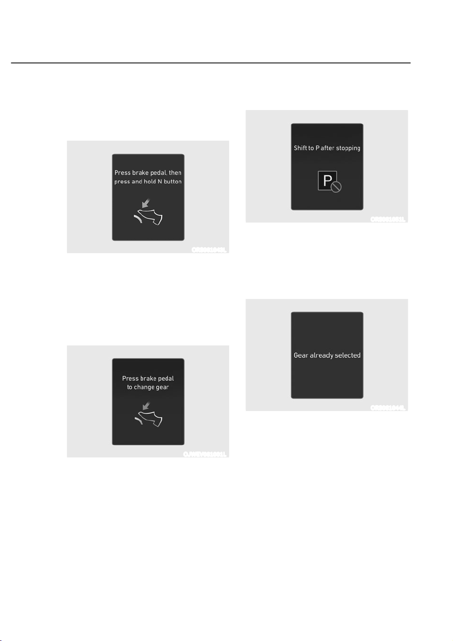
6-17
06
LCD Display Messages (Cluster)
Press brake pedal, then press and
hold N button
ORS061043L
When parking the vehicle in neutral, the
above warning message is displayed if
you do not depress the brake or hold the
shift dial long enough time while turning
the shift dial to right or left. Depress the
brake or turn and hold the shift dial for
enough time.
Press brake pedal to change gear
OJWEV061001L
This message is displayed when the
brake pedal is not depressed while
shifting the gear.
Depress the brake pedal and then shift
the gear.
Shift to P after stopping
ORS061051L
This message is displayed when the gear
is shifted to P (Park) while the vehicle is
moving.
Stop the vehicle before shifting to P
(Park).
Gear already selected
ORS061044L
This message is displayed when the gear
is selected in which the vehicle currently
on.
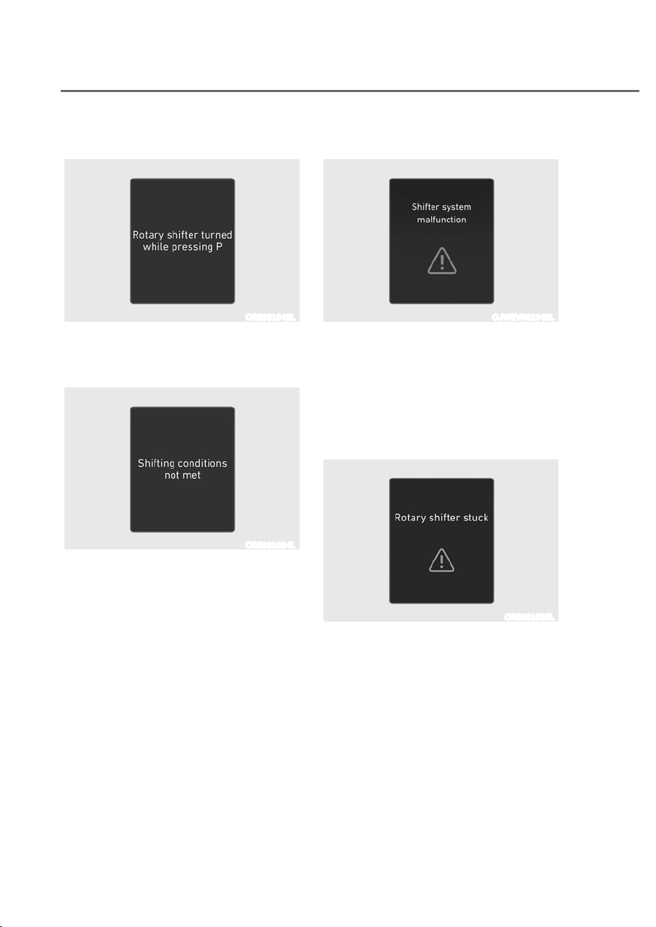
6-18
Driving Your Vehicle
Rotary shifter turned while pressing P
ORS061045L
This message is displayed when you turn
the shift dial while P button is pressed.
Shifting conditions not met
ORS061034L
This message is displayed when engine
RPM is too high, or when driving speed is
too fast to shift the gear.
Decrease vehicle speed or slow down
before shifting the gear.
Shifter system malfunction
OJWEV061040L
This message is displayed when the
transmission or the rotary gear shift dial
does not properly operate in the P (Park)
position.
Have the vehicle inspected by an
authorized retailer of Genesis Branded
products.
Rotary shifter stuck
ORS061035L
If the dial does not return to its original
position after turning the shift dial, the
above warning message is displayed.
Have the vehicle inspected by an
authorized retailer of Genesis Branded
products.
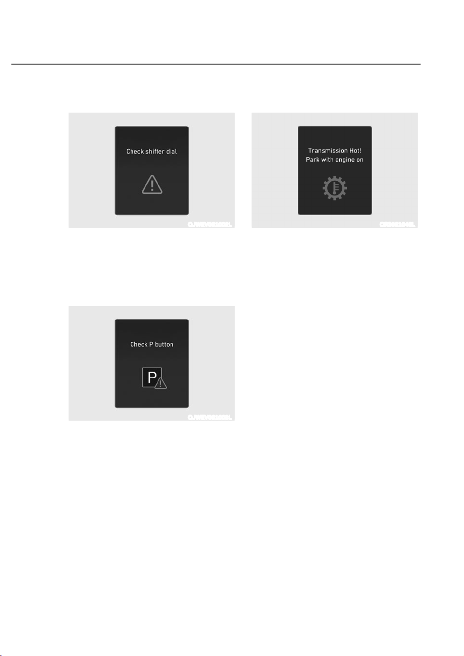
6-19
06
Check shifter dial
OJWEV061002L
This message is displayed when there is
a malfunction with the shift dial.
Have the vehicle inspected by an
authorized retailer of Genesis Branded
products.
Check P button
OJWEV061003L
This message is displayed when there is
a problem with the P button.
Have the vehicle inspected by an
authorized retailer of Genesis Branded
products.
Transmission overheated warning
ORS061046L
Transmission Hot Park with engine on
Repeated sudden acceleration and quick
start may overheat the transmission. If
the transmission is overheated, the self-
protection mode alarms the driver with
an audible sound warning message.
ȉ Move the vehicle to a safe location
and shift the gear to P (Park), and stop
the vehicle with the engine on. Wait
until the transmission is sufficiently
cooled down.

6-20
Driving Your Vehicle
ORS061031L
ehicle Power limited due to high
transmission temperature
If you continue to drive with overheated
transmission, the above warning
message is displayed and self-protection
mode restricts the power output of the
vehicle.
ȉ Move the vehicle to a safe location
and shift the gear to P (Park), and stop
the vehicle with the engine on. Wait
until the transmission is sufficiently
cooled down.
ȉ If the above message is continuously
displayed, have you contact an
authorized retailer of Genesis Branded
products.
ORS061047L
Transmission cooled and safe to drive
This message is displayed when the
vehicle is safe to drive.
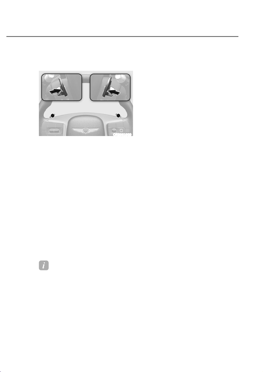
6-21
06
Paddle Shifter (Manual Shift
Mode)
ORS061009
The paddle shifter allows the driver to
shift gears without taking one’s hands off
the steering wheel.
The paddle shifter operates as follow.
ȉ Pull the [+] or [-] paddle shifter once
to shift up or down one gear and the
system changes from automatic shift
mode to manual shift mode.
ȉ To change back to automatic shift
mode from manual shift mode, do one
of the following:
- Pull the [+] paddle shifter for more
than one second.
- Drive the vehicle under 4 mph (7
km/h)
- Gently depress the accelerator
pedal for more than 6 seconds.
- Rotate the shift dial to the D (Drive)
position.
Information
If the and - paddle shifters are pulled
at the same time, gear shift may not occur.
Good Driving Practices
ȉ Never shift the gear from P (Park) or
N (Neutral) to any other position with
the accelerator pedal depressed.
ȉ Never shift the gear into P (Park) when
the vehicle is in motion.
Be sure the vehicle is completely
stopped before you attempt to shift
into R (Reverse) or D (Drive).
ȉ Do not shift the gear to N (Neutral)
when driving. If the gear is shifted to
N (Neutral) while driving, the vehicle
loses the ability to provide engine
braking. Doing so may increase the
risk of an accident.
Also, shifting the gear back to
D (Drive) while the vehicle is
moving may severely damage the
transmission.
ȉ When driving uphill or downhill,
always shift to D (Drive) for driving
forward or shift to R (Reverse) for
driving rearwards. After selecting
D (Drive) or R (Reverse), check the
gear position indicated on the cluster
before driving. If the vehicle moves in
the opposite direction of the selected
gear, the engine may turn off and a
serious accident might occur due to
degraded brake performance.
ȉ Do not drive with your foot resting
on the brake pedal. Even light, but
consistent pedal pressure can result
in the brakes overheating, brake wear
and possibly even brake failure.

6-22
Driving Your Vehicle
ȉ Always apply the parking brake when
leaving the vehicle. Do not depend on
placing the transmission in P (Park) to
keep the vehicle from moving.
ȉ Exercise extreme caution when
driving on a slippery surface. Be
especially careful when braking,
accelerating or shifting gears. On a
slippery surface, an abrupt change
in vehicle speed can cause the drive
wheels to lose traction and may cause
loss of vehicle control resulting in an
accident
ȉ Optimum vehicle performance and
economy is obtained by smoothly
depressing and releasing the
accelerator.
WARNING
To reduce the risk of SERIOUS INJURY
or DEATH:
ȉ ALWAYS wear your seat belt. In a
collision, an unbelted occupant
is significantly more likely to be
seriously injured or killed than a
properly belted occupant.
ȉ Avoid high speeds when cornering or
turning.
ȉ Do not make quick steering wheel
movements, such as sharp lane
changes or fast, sharp turns.
ȉ The risk of rollover is greatly
increased if you lose control of your
vehicle at highway speeds.
ȉ Loss of control often occurs if two or
more wheels drop off the roadway
and the driver over steers to reenter
the roadway.
ȉ In the event your vehicle leaves
the roadway, do not steer sharply.
Instead, slow down before pulling
back into the travel lanes.
ȉ Genesis Branded Vehicle
recommends you to follow all posted
speed limits.
NOTICE
Kickdown mechanism
Use the kickdown mechanism for
maximum acceleration. Depress the
accelerator pedal beyond the pressure
point. The automatic transmission will
shift to a lower gear depending on the
engine speed.

6-23
06
Power-Assist Brakes
Your vehicle has power-assisted brakes
that adjust automatically through normal
usage.
In the event of a vehicle power failure,
the power assist for the brakes will not
work. You can still stop your vehicle, but
it will require greater force and increased
pedal travel than normal. The stopping
distance, however, will be longer than
with power brakes.
Information
ȉ When the brake pedal is depressed
under certain driving conditions
or weather conditions, you may
temporarily hear a noise. This is
normal and does not indicate a problem
with your brakes.
ȉ While driving on a road with deicing
chemicals, brake noise or abnormal
tire wear may occur due to deicing
chemicals. In a safe traffic condition,
additionally apply the brakes to remove
deicing chemicals on the brake discs
and pads.
WARNING
Take the following precautions:
ȉ Do not drive with your foot resting
on the brake pedal. This will create
abnormal high brake temperatures,
excessive brake lining and pad wear,
and increased stopping distances.
ȉ When descending down a long or
steep hill, use the paddle shifter
and manually downshift to a
lower gear in order to control your
speed without using the brake
pedal excessively. Applying the
brakes continuously will cause
the brakes to overheat and could
result in a temporary loss of braking
performance.
ȉ Wet brakes may impair the vehicle's
ability to safely slow down; the
vehicle may also pull to one side
when the brakes are applied.
Applying the brakes lightly will
indicate whether they have been
affected in this way. Always test your
brakes in this fashion after driving
through deep water. To dry the
brakes, lightly tap the brake pedal to
heat up the brakes while maintaining
a safe forward speed until brake
performance returns to normal.
Avoid driving at high speeds until the
brakes function correctly.
Disc Brakes Wear Indicator
When your brake pads are worn and new
pads are required, you will hear a high
pitched warning sound from your front
or rear brakes. You may hear this sound
come and go or it may occur whenever
you depress the brake pedal.
NOTICE
To avoid costly brake repairs, do not
continue to drive with worn brake pads.
Information
Always replace brake pads as complete
front or rear axle sets.
BRAKING SYSTEM
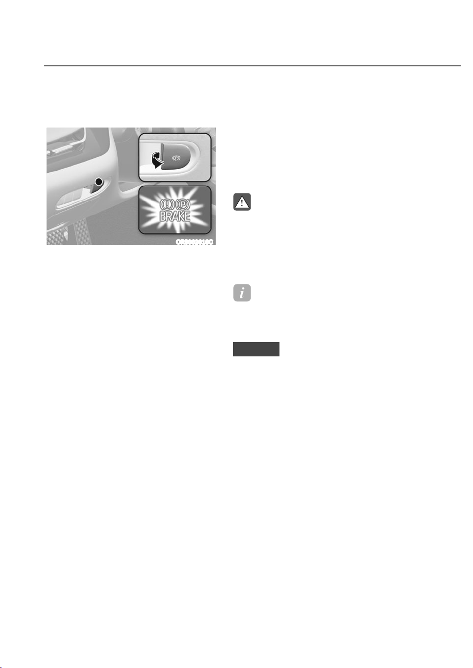
6-24
Driving Your Vehicle
Electronic Parking Brake (EPB)
Applying the parking brake
ORS062010C
To apply EPB (Electronic Parking Brake):
1. Depress and hold the brake pedal.
2. Pull up the EPB switch.
Make sure the Parking Brake warning
light comes on.
EPB (Electronic Parking Brake) may be
automatically applied when:
ȉ Requested by other systems
ȉ The driver turns the vehicle off while
Auto Hold is operating.
Emergency braking
If there is a problem with the brake
pedal while driving, emergency braking
is possible by pulling up and holding
the EPB switch. Braking is possible only
while you are holding the EPB switch.
However, braking distance will be longer
than normal.
WARNING
To reduce the risk of SERIOUS INJURY
or DEATH, do not operate the EPB
while the vehicle is moving except
in an emergency situation. It could
damage the brake system and lead to
an accident.
Information
During emergency braking, the Parking
Brake warning light will illuminate to
indicate that the system is operating.
NOTICE
If you continuously notice a noise or
burning smell when the EPB is used for
emergency braking, have the system
checked by an authorized retailer of
Genesis Branded products.
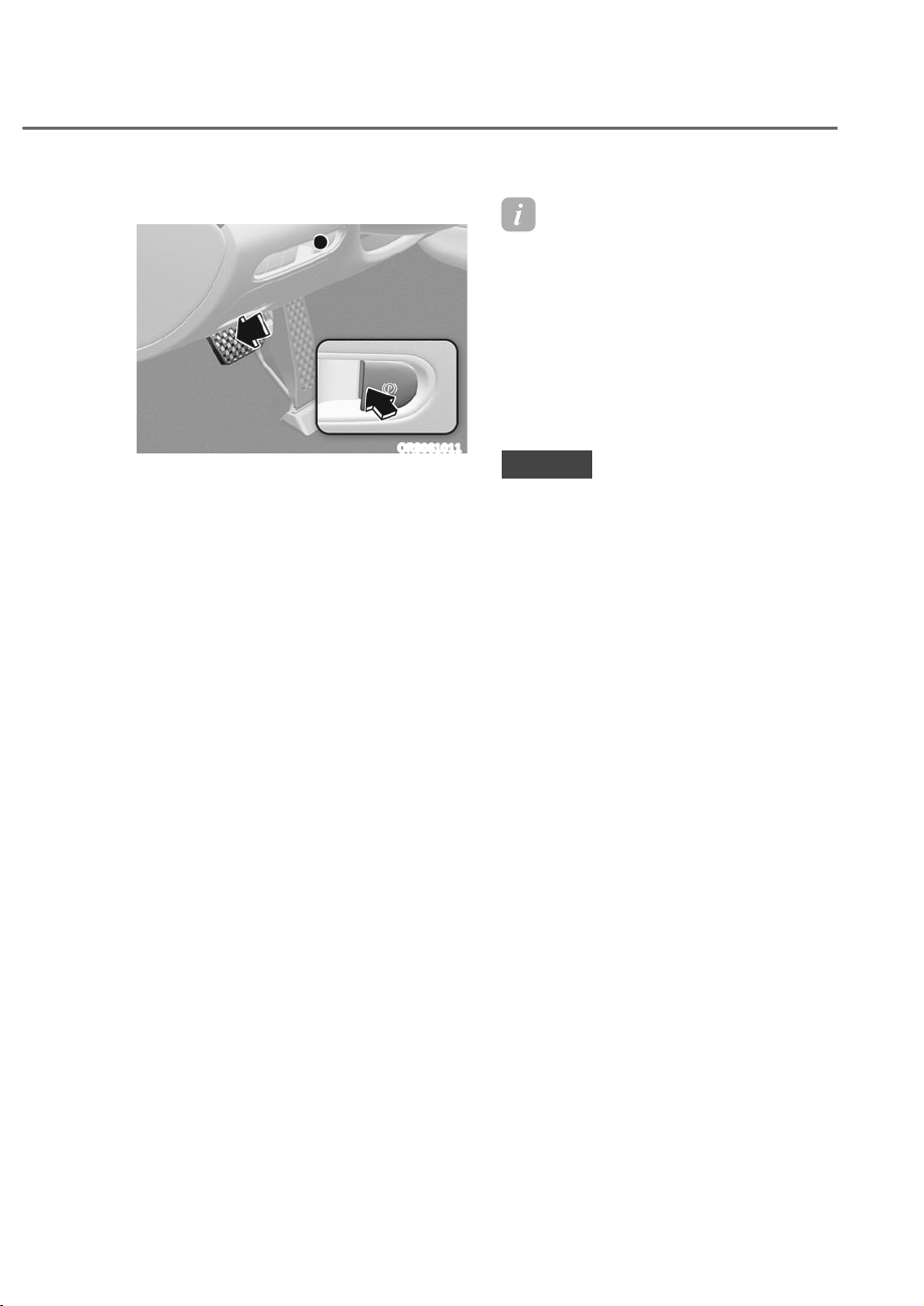
6-25
06
Releasing the parking brake
ORS061011
To release EPB (Electronic Parking
Brake):
1. Press the Engine Start/Stop button to
the ON or START position.
2. Press the EPB switch while depressing
the brake pedal.
Make sure the Parking Brake warning
light goes off.
To release EPB (Electronic Parking Brake)
automatically do one of the following:
ȉ With the engine running depress the
brake pedal and shift out of P (Park) or
N (Neutral) to R (Reverse) or D (Drive).
Take your foot off the brake pedal
after the Parking Brake warning light
is off.
ȉ Depress the accelerator pedal when
all the conditions below are satisfied.
- The engine is running
- The seatbelt is fastened
- The driver’s door, hood, and trunk
is closed
- The gear is in R (Reverse) or D
(Drive)
Make sure the Parking Brake warning
light is off before driving.
Information
ȉ For your safety, you can engage EPB
even though the Engine Stop/Start
button is in the FF position (only if
battery power is available), but you
cannot release it.
ȉ For your safety, depress the brake
pedal and release the parking brake
manually with the EPB switch when
you drive downhill or when backing up
the vehicle.
NOTICE
ȉ If the Parking Brake warning light is
still on even though the EPB has been
released, have the system checked
by an authorized retailer of Genesis
Branded products.
ȉ Do not drive your vehicle with EPB
applied. It may cause excessive brake
pad and brake rotor wear.

6-26
Driving Your Vehicle
Warning messages
ORS061053L
To release EPB, fasten seatbelt, close door,
hood and trunk
ȉ If you try to drive with EPB applied, a
warning will sound and a message will
appear.
ȉ If the driver's seat belt is unfastened
and the engine hood or trunk is
opened, a warning will sound and a
message will appear.
ȉ If there is a problem with the vehicle,
a warning may sound and a message
may appear.
If the situation occurs, depress the brake
pedal and release EPB by pressing the
EPB switch.
WARNING
ȉ Whenever leaving the vehicle or
parking, always come to a complete
stop and continue to depress the
brake pedal.
Shift the gear into P (Park), pull the
EPB switch, and press the Engine
Start/Stop button to the OFF
position. Take the Key with you when
leaving the vehicle.
Vehicles not fully engaged in P (Park)
with the parking brake set are at risk
for moving inadvertently and causing
injury to yourself or others.
ȉ NEVER allow anyone who is
unfamiliar with the vehicle to touch
the EPB switch. If EPB is released
unintentionally, serious injury may
occur.
ȉ Only release EPB when you are
seated inside the vehicle with your
foot firmly on the brake pedal.
NOTICE
ȉ Do not apply the accelerator pedal
while the parking brake is engaged.
If you depress the accelerator pedal
with EPB engaged, a warning will
sound and a message will appear.
Damage to the parking brake may
occur.
ȉ Driving with the parking brake on
can overheat the braking system and
cause premature wear or damage
to brake parts. Make sure EPB is
released and the Parking Brake
warning light is off before driving.
Information
ȉ A clicking sound may be heard while
operating or releasing the EPB. These
conditions are normal and indicate that
EPB is functioning properly.
ȉ When leaving your keys with a parking
attendant or assistant, make sure to
inform him/her how to operate EPB.
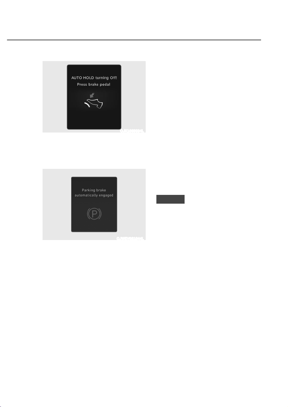
6-27
06
OJX1069034L
AUT H LD turning ff Press brake
pedal
When the conversion from Auto Hold to
EPB is not working properly a warning
will sound and a message will appear.
OJWEV061044L
Parking brake automatically engaged
When EPB is applied while Auto Hold
is activated, a warning will sound and a
message will appear.
EPB malfunction
Electronic Parking Brake (EPB) warning
light illuminates if the Engine Start/Stop
button is pressed to the ON position and
goes off in approximately 3 seconds if
the system is operating normally.
If the EPB warning light remains on,
comes on while driving, or does not
come on when the Engine Start/Stop
button is pressed to the ON position,
this indicates that the EPB may have
malfunctioned.
If this occurs, have the system checked
by an authorized retailer of Genesis
Branded products.
The EPB warning light may illuminate
when the ESC indicator comes on to
indicate that ESC is not working properly,
but it does not indicate a malfunction of
EPB.
NOTICE
ȉ If the EPB warning light is still
on, have the system checked by
an authorized retailer of Genesis
Branded products.
ȉ If the Parking Brake warning light
does not illuminate or blinks even
though the EPB switch was pulled
up, EPB may not be applied.
ȉ If the Parking Brake warning light
blinks when the EPB warning light is
on, press the switch, and then pull it
up. Repeat this one more time. If the
EPB warning does not go off, have
the system checked by an authorized
retailer of Genesis Branded products.
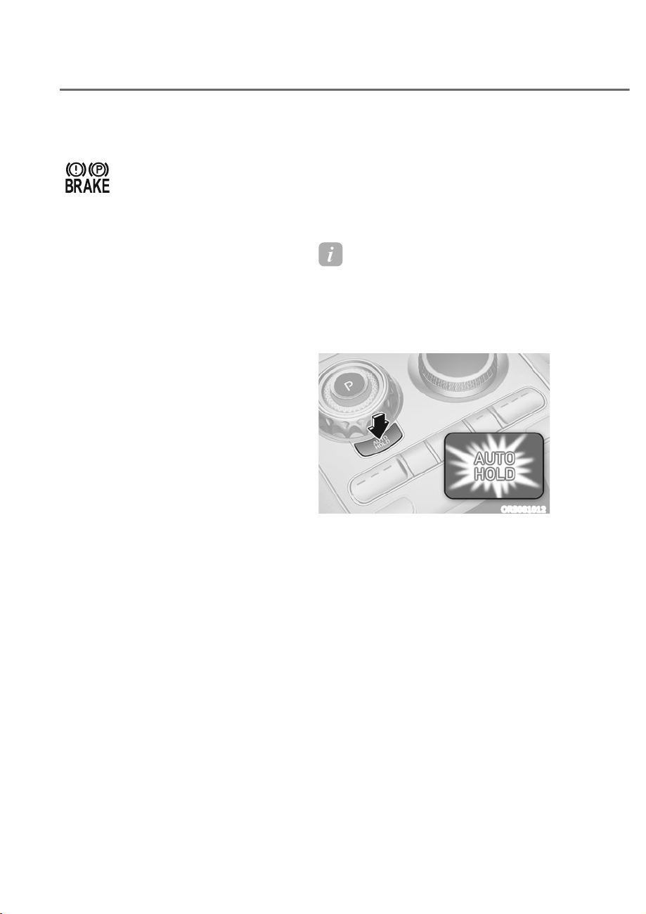
6-28
Driving Your Vehicle
Parking brake warning light
Check the Parking Brake
warning light by pressing the
Engine Stop/Start button to the
ON position.
This light will be illuminated when the
parking brake is applied with the Engine
Stop/Start button in the START or ON
position.
Before driving, be sure the parking
brake is released and the Parking Brake
warning light is OFF.
If the Parking Brake warning light
remains on after the parking brake is
released while the engine is running,
there may be a malfunction in the
brake system. Immediate attention is
necessary.
If at all possible, cease driving the vehicle
immediately. If that is not possible,
use extreme caution while operating
the vehicle and only continue to drive
the vehicle until you can reach a safe
location.
When the EPB (Electronic Parking
Brake) does not release
If the EPB does not release normally,
contact an authorized retailer of Genesis
Branded products by loading the vehicle
on a flatbed tow truck and have the
system checked.
Auto Hold
Auto Hold maintains the vehicle in a
standstill even though the brake pedal is
not depressed after the driver brings the
vehicle to a complete stop by depressing
the brake pedal.
Information
The Auto Hold n or ff setting is
maintained when the vehicle is turned
off. When the vehicle is restarted the last
setting for Auto Hold is applied.
To apply:
ORS061012
1. With the driver's door and engine
hood closed, depress the brake
pedal and then press the AUTO
HOLD switch. The white AUTO HOLD
indicator will come on and the system
will be in the standby position.
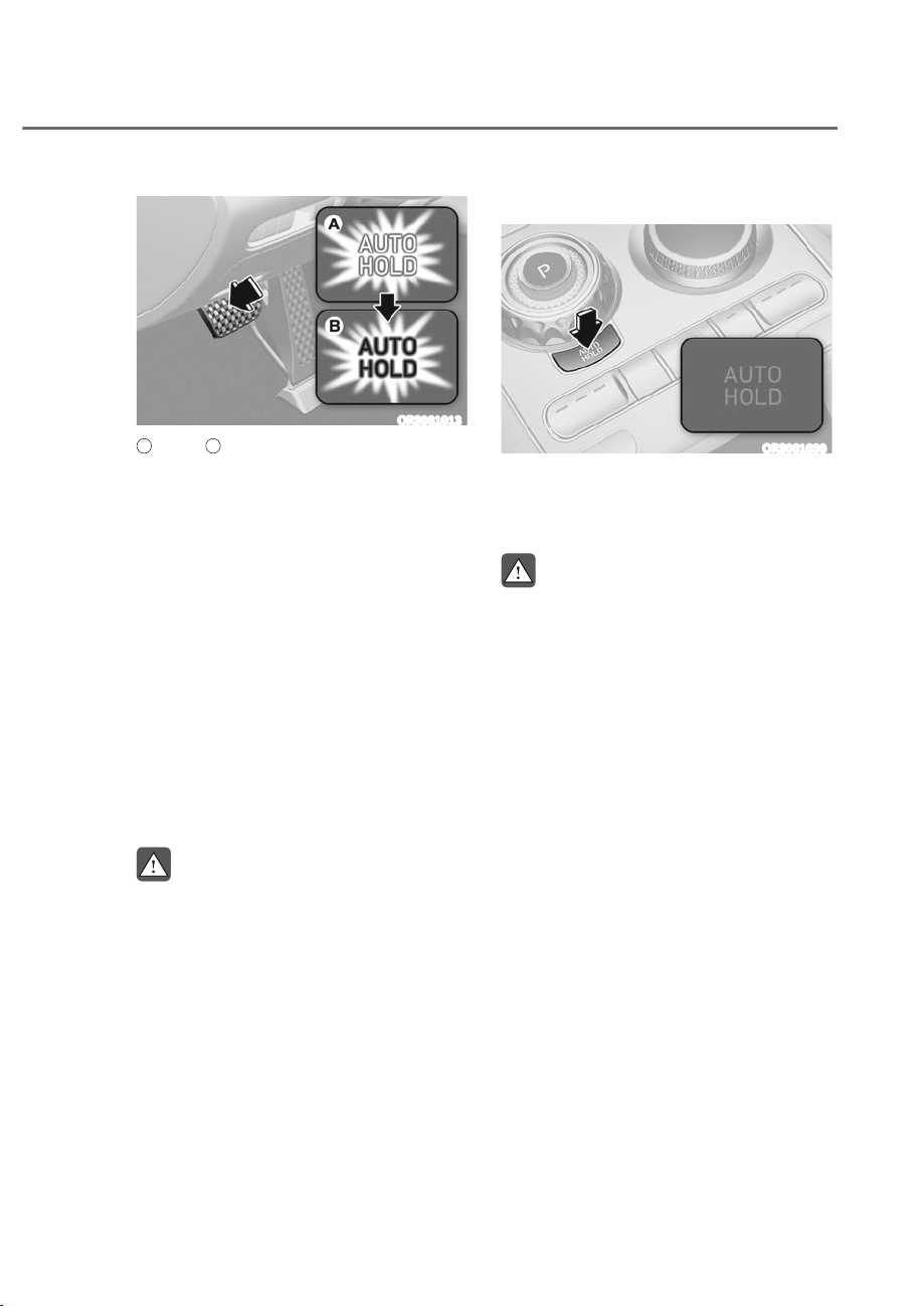
6-29
06
ORS061013
A
: White,
B
: Green
2. When you stop the vehicle completely
by depressing the brake pedal, Auto
Hold maintains the brake pressure
to hold the vehicle stationary. The
indicator changes from white to
green.
3. The vehicle will remain stationary
even if you release the brake pedal.
4. If EPB is applied, Auto Hold will be
released.
To release:
If you depress the accelerator pedal
with the gear in D (Drive), R (Reverse) or
Manual shift mode, the Auto Hold will be
released automatically and the vehicle
will start to move. The AUTO HOLD
indicator changes from green to white.
WARNING
When Auto Hold is automatically
released by depressing the accelerator
pedal, always take a look around your
vehicle.
Slowly depress the accelerator pedal
for a smooth start.
To cancel:
ORS061030
1. Depress and hold the brake pedal.
2. Press the AUTO HOLD switch.
The AUTO HOLD indicator will turn off.
WARNING
To prevent, unexpected and sudden
vehicle movement, ALWAYS press your
foot on the brake pedal to cancel Auto
Hold before you:
- Drive downhill.
- Drive the vehicle in R (Reverse).
- Park the vehicle.
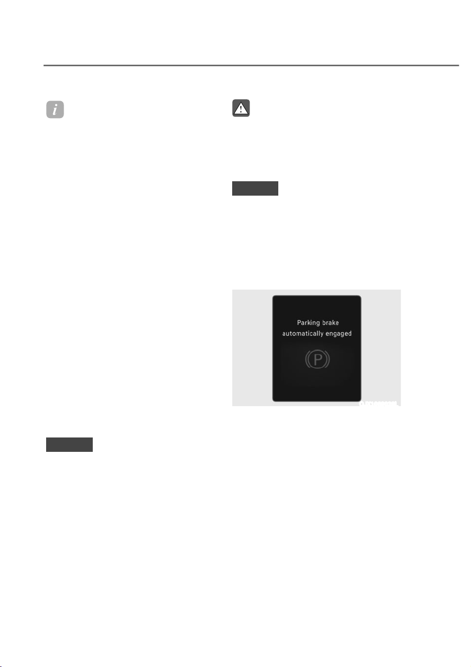
6-30
Driving Your Vehicle
Information
ȉ The Auto Hold does not operate when:
- The driver's door is opened
- The engine hood is opened
- The gear is in P (Park)
- EPB is applied
ȉ For your safety, the Auto Hold
automatically switches to EPB when:
- The driver's door is opened
- The engine hood is opened
- The vehicle is in a standstill for more
than 10 minutes
- The vehicle is standing on a steep
slope
- The vehicle moved several times
In these cases, the Parking Brake
warning light comes on, the AUT
H LD indicator changes from green
to white, and a warning sound and a
message will appear to inform you that
EPB has been automatically engaged.
Before driving off again, depress the
brake pedal, check the surrounding
area near your vehicle and release the
parking brake manually with the EPB
switch.
ȉ While operating Auto Hold, you may
hear mechanical noise. However, it is
normal operating noise.
NOTICE
If the AUTO HOLD indicator changes
to yellow, Auto Hold is not working
properly. Contact an authorized retailer
of Genesis Branded products.
WARNING
ȉ Depress the accelerator pedal slowly
when you start the vehicle.
ȉ For your safety, cancel Auto Hold
when you drive downhill, back up the
vehicle or park the vehicle.
NOTICE
If there is a malfunction with the
driver's door or engine hood open
detection system, Auto Hold may not
work properly.
Contact an authorized retailer of
Genesis Branded products.
Warning messages
OJX1069028L
Parking brake automatically engaged
When EPB is applied while Auto Hold
is activated, a warning will sound and a
message will appear.
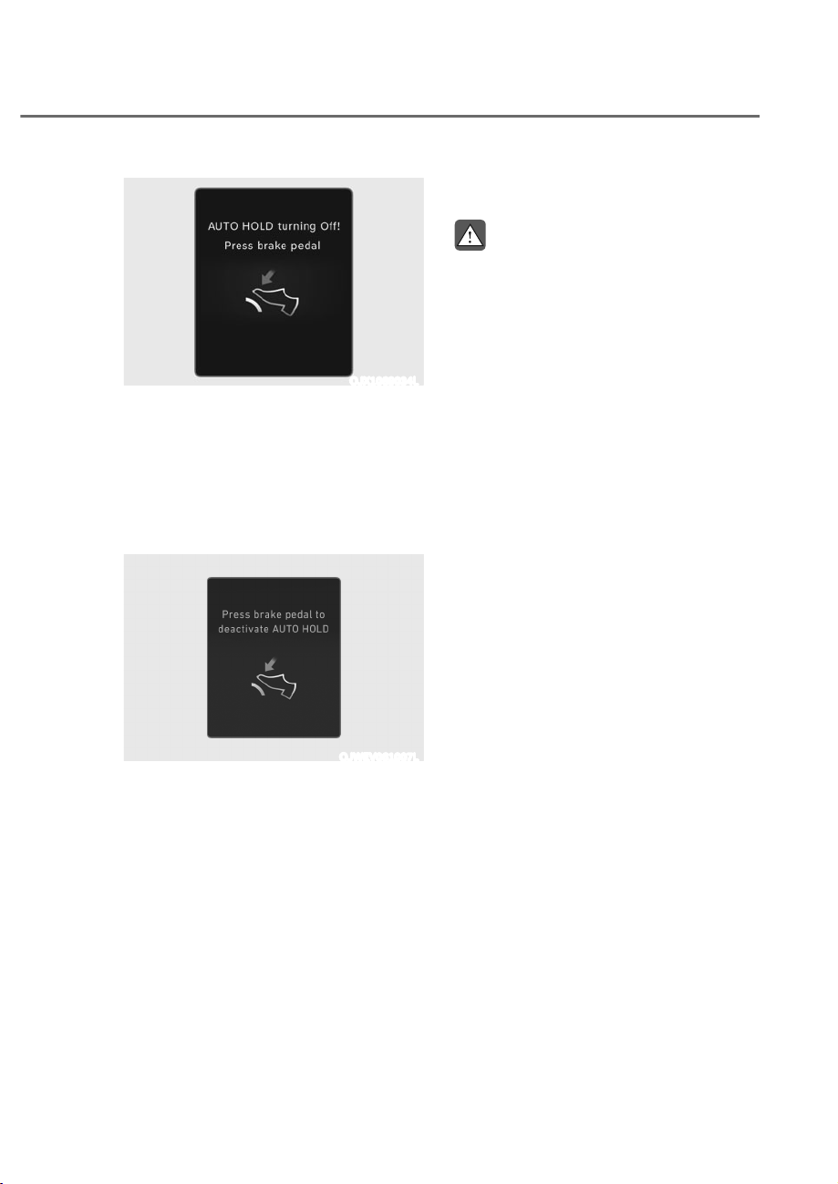
6-31
06
OJX1069034L
AUT H LD turning ff Press brake
pedal
When the conversion from Auto Hold to
EPB is not working properly a warning
will sound and a message will appear.
When this message is displayed, Auto
Hold and EPB may not operate. For your
safety, depress the brake pedal.
OJWEV061007L
Press brake pedal to deactivate AUT
HLD
If you did not apply the brake pedal when
you release Auto Hold by pressing the
AUTO HOLD switch, a warning will sound
and a message will appear.
Anti-Lock Brake System (ABS)
WARNING
Anti-Lock Braking System (ABS) or
Electronic Stability Control (ESC)
system will not prevent accidents
due to improper or dangerous driving
maneuvers. Even though vehicle
control is improved during emergency
braking, always maintain a safe
distance between you and objects
ahead of you. Vehicle speeds should
always be reduced during extreme
road conditions. The braking distance
for vehicles equipped with ABS or ESC
may be longer than for those without
these systems in the following road
conditions.
Drive your vehicle at reduced speeds
during the following conditions:
ȉ Rough, gravel or snow-covered
roads.
ȉ On roads where the road surface is
pitted or has different surface height.
ȉ Tire chains are installed on your
vehicle.
The safety features of ABS or ESC
equipped vehicle should not be tested
by high speed driving or cornering. This
could endanger the safety of yourself or
others.
ABS is an electronic braking system that
helps prevent a braking skid. ABS allows
the driver to steer and brake at the same
time.

6-32
Driving Your Vehicle
Using ABS
To obtain the maximum benefit from
your ABS in an emergency situation,
do not attempt to modulate your brake
pressure and do not try to pump your
brakes. Depress your brake pedal as hard
as possible.
When you apply your brakes under
conditions which may lock the wheels,
you may hear sounds from the brakes,
or feel a corresponding sensation in the
brake pedal. This is normal and it means
your ABS is active.
ABS does not reduce the time or distance
it takes to stop the vehicle.
Always maintain a safe distance from the
vehicle in front of you.
ABS will not prevent a skid that results
from sudden changes in direction, such
as trying to take a corner too fast or
making a sudden lane change. Always
drive at a safe speed for the road and
weather conditions.
ABS cannot prevent a loss of stability.
Always steer moderately when braking
hard. Severe or sharp steering wheel
movement can still cause your vehicle to
veer into oncoming traffic or off the road.
On loose or uneven road surfaces,
operation of the anti-lock brake system
may result in a longer stopping distance
than for vehicles equipped with a
conventional brake system.
The ABS (
) warning light will stay
on for several seconds after the Engine
Start/Stop button is in the ON position.
During that time, ABS will go through
self-diagnosis and the light will go off if
everything is normal. If the light stays on,
you may have a problem with your ABS.
Contact an authorized retailer of Genesis
Branded products as soon as possible.
WARNING
If the ABS ( ) warning light is on and
stays on, you may have a problem with
the ABS. Your power brakes will work
normally. To reduce the risk of serious
injury or death, contact your authorized
retailer of Genesis Branded products as
soon as possible.
NOTICE
When you drive on a road having poor
traction, such as an icy road, and apply
your brakes continuously, ABS will be
active continuously and the ABS (
)
warning light may illuminate. Pull your
vehicle over to a safe place and turn the
vehicle off.
Restart the vehicle. If the ABS warning
light is off, then your ABS system is
normal.
Otherwise, you may have a problem
with your ABS system. Contact an
authorized retailer of Genesis Branded
products as soon as possible.
Information
When you ump start your vehicle because
of a drained battery, the ABS (
ehicle b
(
)
warning light may turn on at the same
time. This happens because of the low
battery voltage. It does not mean your
ABS is malfunctioning. Have the battery
recharged before driving the vehicle.
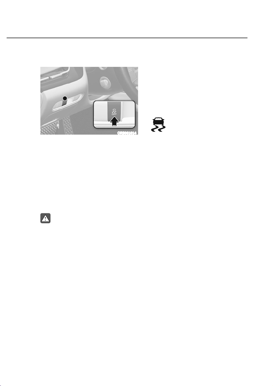
6-33
06
Electronic Stability Control (ESC)
ORS061014
Electronic Stability Control helps to
stabilize the vehicle during cornering
maneuvers.
ESC checks where you are steering and
where the vehicle is actually going. ESC
applies braking pressure to any one of
the vehicle's brakes and intervenes in the
engine management system to assist the
driver with keeping the vehicle on the
intended path. It is not a substitute for
safe driving practices. Always adjust your
speed and driving to the road conditions.
WARNING
Never drive too fast for the road
conditions when cornering. ESC will not
prevent accidents.
Excessive speed in turns, abrupt
maneuvers, and hydroplaning on wet
surfaces can result in severe accidents.
ESC operation
ES N condition
When the Engine Start/Stop button is
in the ON position, ESC and the ESC
OFF indicator lights illuminate for
approximately three seconds. After both
lights go off, ESC is enabled.
When operating
When ESC is in operation, the
ESC indicator light blinks:
ȉ When you apply your brakes under
conditions which may lock the wheels,
you may hear sounds from the brakes,
or feel a corresponding sensation in
the brake pedal. This is normal and it
means your ESC is active.
ȉ When ESC activates, the engine may
not respond to the accelerator as it
does under routine conditions.
ȉ If Smart Cruise Control was in use
when ESC activates, Smart Cruise
Control automatically disengages.
Smart Cruise Control can be
reengaged when the road conditions
allow. See “Smart Cruise Control
(SCC)” section in chapter 7 (if
equipped).
ȉ When moving out of the mud or
driving on a slippery road, the engine
RPM (revolutions per minute) may
not increase even if you press the
accelerator pedal deeply. This is to
maintain the stability and traction of
the vehicle and does not indicate a
problem.
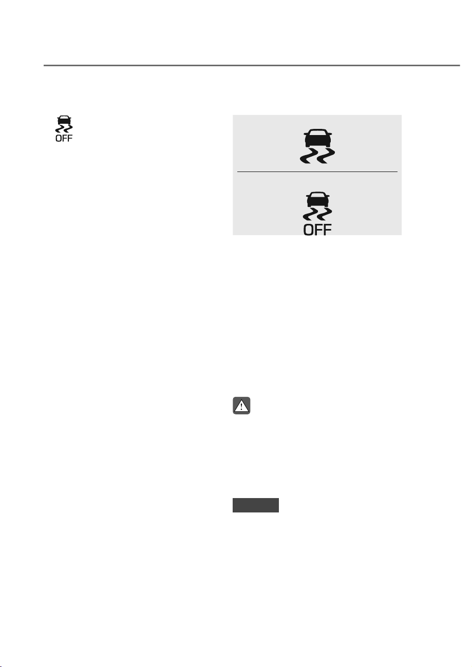
6-34
Driving Your Vehicle
ES FF condition
To cancel ESC operation:
ȉ State 1
Press the ESC OFF button briefly.
The ESC OFF indicator light and/or
message ‘Traction and Stability Control
limited’ will illuminate. In this state, the
traction control function of ESC (engine
management) is disabled, but the
brake control function of ESC (braking
management) still operates.
ȉ State 2
Press and hold the ESC OFF button
continuously for more than 3 seconds.
The ESC OFF indicator light and/or
message 'Traction & Stability Control
disabled' illuminates and a warning
chime sounds. In this state, both the
traction control function of ESC (engine
management) and the brake control
function of ESC (braking management)
are disabled.
If the Engine Start/Stop button is pressed
to the OFF position when ESC is off, ESC
remains off. Upon restarting the vehicle,
ESC will automatically turn on again.
Indicator lights
Ŷ
ESC indicator light (blinks)
Ŷ
ESC OFF indicator light (comes on)
When the Engine Start/Stop button is
pressed to the ON position, the ESC
indicator light illuminates, then goes off
if the ESC system is operating normally.
The ESC indicator light blinks whenever
ESC is operating.
If the ESC indicator light stays on, your
vehicle may have a malfunction with
the ESC system. When this warning light
illuminates, have the vehicle checked by
an authorized retailer of Genesis Branded
products as soon as possible.
The ESC OFF indicator light comes on
when ESC is turned off.
WARNING
When ESC is blinking, this indicates ESC
is active:
Drive slowly and NEVER attempt to
accelerate. NEVER turn ESC off while
the ESC indicator light is blinking or you
may lose control of the vehicle resulting
in an accident.
NOTICE
Driving with wheels and tires with
different sizes may cause the ESC
system to malfunction. Before replacing
tires, make sure all four tires and wheels
are the same size. Never drive the
vehicle with different sized wheels and
tires installed.

6-35
06
ESC OFF usage
When Driving
The ESC OFF mode should only be used
briefly to help free the vehicle if stuck in
snow or mud, by temporarily stopping
operation of ESC, to maintain wheel
torque.
To turn ESC off while driving, press the
ESC OFF button while driving on a flat
road surface.
NOTICE
To prevent damage to the transmission:
ȉ Do not allow wheel(s) of one axle to
spin excessively while the ESC, ABS,
and Parking Brake warning lights
are displayed. The repairs would not
be covered by the vehicle warranty.
Reduce engine power and do not
spin the wheel(s) excessively while
these lights are displayed.
ȉ When operating the vehicle
on a dynamometer, make sure
ESC is turned off (ESC OFF light
illuminated).
Information
Turning ES off does not affect ABS or
standard brake system operation.
Vehicle Stability Management
(VSM)
Vehicle Stability Management is a
function of the Electronic Stability
Control (ESC) system. It helps the vehicle
stay stable when accelerating or braking
suddenly on wet, slippery and rough
roads where traction over the four tires
can suddenly become uneven.
WARNING
Take the following precautions when
using Vehicle Stability Management:
ȉ ALWAYS check the speed and the
distance to the vehicle ahead. VSM
is not a substitute for safe driving
practices.
ȉ Never drive too fast for the road
conditions. VSM will not prevent
accidents. Excessive speed in bad
weather, on slippery and uneven
roads can result in severe accidents.
6-36
Driving Your Vehicle
VSM operation
When operating
When you apply your brakes under
conditions which may activate ESC, you
may hear sounds from the brakes, or feel
a corresponding sensation in the brake
pedal. This is normal and it means your
VSM is active.
Information
SM does not operate when:
ȉ Driving on a banked road such as
gradient or incline.
ȉ Driving in reverse.
ȉ The ES FF indicator light is on.
ȉ The MDPS (Motor Driven Power
Steering) warning light (
(
) is on or
blinks.
SM FF condition
To cancel VSM operation, press the ESC
OFF button. ESC OFF (
) indicator light
will illuminate.
To turn on VSM, press the ESC OFF
button again. The ESC OFF indicator light
will go out.
WARNING
If the ESC ( ) indicator light or MDPS
(
) warning light stays illuminated
or blinks, your vehicle may have a
malfunction with the VSM system.
When the warning light illuminates,
have the vehicle checked by an
authorized retailer of Genesis Branded
products as soon as possible.
NOTICE
Driving with wheels and tires with
different sizes may cause the VSM
system to malfunction. Before replacing
tires, make sure all four tires and wheels
are the same size. Never drive the
vehicle with different sized tires and
wheels installed.

6-37
06
Hill-Start Assist Control (HAC)
Hill-Start Assist Control helps prevent
the vehicle from rolling backwards
when starting a vehicle from a stop on
a hill. The system operates the brakes
automatically for approximately 2
seconds (maximum of 5 secondswhen
the accelerator pedal is slightly
depressed during HAC operation) and
releases the brake after 2 seconds or
when the accelerator pedal is depressed.
WARNING
Always be ready to depress the
accelerator pedal when starting off
an incline. Hill-Start Assist Control
activates only for approximately 2
seconds (maximum of 5 seconds
when the accelerator pedal is slightly
depressed during HAC operation).
Information
ȉ Hill-Start Assist ontrol does not
operate when the gear is shifted to P
(Park) or N (Neutral).
ȉ Hill-Start Assist ontrol activates even
when the ES (Electronic Stability
ontrol) is off. However, it does not
activate, when ES does not operate
normally.
Brake Assistant System (BAS)
The Brake Assistant System provides
additional pressure when the brake pedal
is momentarily and strongly depressed
in a situation sudden braking is required
while driving.
The Brake Assistant System reduces the
time for ABS (Anti-Lock Brake System)
control to enter and consequently
reduces the braking distance, by
providing additional pressure up to the
point of ABS intervention.
BAS operation
ȉ When the vehicle speed is more than
19 mph (30 km/h) and the ABS control
is not entered.
ȉ When the brake pedal is depressed
strongly over a certain level.
ȉ When the friction of the road surface
is above a certain level.
BAS operation off
ȉ The vehicle speed is below 6 mph (10
km/h).
ȉ The brake pedal is depressed lightly or
firmly over a certain condition.
ȉ The friction of the road surface is
below a certain level.
WARNING
The system may not operate depending
on driver's driving habit, the degree to
which the brake pedal is depressed and
the road surface condition.

6-38
Driving Your Vehicle
Good Braking Practices
WARNING
Whenever leaving the vehicle or
parking, always come to a complete
stop and continue to depress the brake
pedal. Shift the gear to the P (Park)
position, then apply the parking brake,
and press the Engine Start/Stop button
to the OFF position.
Vehicles parked with the parking brake
not applied or not fully engaged may
roll inadvertently and may cause injury
to the driver and others. ALWAYS apply
the parking brake before exiting the
vehicle.
Wet brakes can be dangerous! The
brakes may get wet if the vehicle is
driven through standing water or if it
is washed. Your vehicle will not stop as
quickly if the brakes are wet. Wet brakes
may cause the vehicle to pull to one side.
To dry the brakes, apply the brakes
lightly until the braking action returns to
normal. If the braking action does not
return to normal, stop as soon as it is safe
to do so and we recommend that you call
an authorized retailer of Genesis Branded
products for assistance.
DO NOT drive with your foot resting on
the brake pedal. Even light, but constant
pedal pressure can result in the brakes
overheating, brake wear, and possibly
even brake failure.
If a tire goes flat while you are driving,
apply the brakes gently and keep the
vehicle pointed straight ahead while you
slow down. When you are moving slowly
enough for it to be safe to do so, pull off
the road and stop in a safe location.
Keep your foot firmly on the brake pedal
when the vehicle is stopped to prevent
the vehicle from rolling forward.

6-39
06
All Wheel Drive (AWD) delivers engine
power to front and rear wheels for
maximum traction. AWD is useful when
extra traction is required, such as when
driving on, muddy, wet, or snow-covered
roads.
WARNING
To reduce the risk of SERIOUS INJURY
or DEATH:
ȉ Do not drive in conditions that
exceed the vehicles intended
design such as challenging off-road
conditions.
ȉ Avoid high speeds when cornering or
turning.
ȉ Do not make quick steering wheel
movements, such as sharp lane
changes or fast, sharp turns.
ȉ The risk of a rollover is greatly
increased if you lose control of your
vehicle at highway speeds.
ȉ Loss of control often occurs if two or
more wheels drop off the roadway
and the driver over steers to reenter
the roadway.
ȉ In the event your vehicle leaves
the roadway, do not steer sharply.
Instead, slow down before pulling
back into the travel lanes.
WARNING
If the AWD ( ) warning light stays on
the instrument cluster, your vehicle
may have a malfunction with the
AWD system. Whenever the AWD
(
) warning light illuminates, have
the vehicle inspected by an authorized
retailer of Genesis Branded products as
soon as possible.
NOTICE
ȉ Do not drive in water if the water
level is higher than the bottom of the
vehicle.
ȉ Check your brake condition once
you are out of mud or water. Depress
the brake pedal several times as you
move slowly until you feel normal
braking condition is returned.
ȉ Shorten your scheduled
maintenance interval if you drive in
off-road conditions such as sand,
mud or water (see "Maintenance
Under Severe Usage Conditions"
section in chapter 9).
ȉ Always wash your vehicle thoroughly
after off road use, especially the
bottom of the vehicle.
ȉ Be sure to equip the vehicle with four
tires of the same size and type.
ȉ Make sure that a full time AWD
vehicle is towed by a flat bed tow
truck.
$//:+((/'5,9(ʚ$:'ʛʚ,)(48,33('ʛ

6-40
Driving Your Vehicle
All Wheel Drive (AWD) Operation
If the AWD system determines there is a
need for four wheel drive, the engine's
driving power is distributed to all four
wheels automatically.
For safe AWD operation
Before driving
ȉ Make sure all passengers are wearing
seat belts.
ȉ Sit upright and closer to the steering
wheel than usual. Adjust the steering
wheel to a position comfortable for
you to drive.
Driving on snow-covered or icy roads
ȉ Start off slowly by applying the
accelerator pedal gently.
ȉ Use snow tires or tire chains.
ȉ Keep sufficient distance between your
vehicle and the vehicle in front of you.
ȉ Apply engine braking during
deceleration by using the paddle
shifter (manual shift mode) and
manually selecting a lower gear.
ȉ Avoid speeding, rapid acceleration,
sudden brake applications, and sharp
turns to prevent skids.
Driving in sand or mud
ȉ Maintain slow and constant speed.
ȉ Use tire chains driving in mud if
necessary.
ȉ Keep sufficient distance between your
vehicle and the vehicle in front of you.
ȉ Reduce vehicle speed and always
check the road condition.
ȉ Avoid speeding, rapid acceleration,
sudden brake applications, and sharp
turns to prevent getting stuck.
NOTICE
When the vehicle is stuck in snow, sand
or mud, place a nonslip material under
the drive wheels to provide traction
OR slowly spin the wheels in forward
and reverse directions which causes
a rocking motion that may free the
vehicle.
However, avoid running the engine
continuously at high RPM, doing so may
damage the AWD system.
Information
ȉ When using Snow Tires, mount them
on all four wheels.
ȉ When using tire chains, install them on
the rear tires. However, driving speed
must be below 18 mph (30 km/h) and
minimize the driving distance. High
speed or long-term driving with the
chains installed may malfunction or
damage the AWD system.
ȉ If tire chains must be used, use
AutoSock (fabric snow chain) and
install the tire chain after reviewing
the instructions provided with the tire
chains.
For more information on Snow Tires and
Tire hains, refer to "Winter Driving" in
this chapter.

6-41
06
Driving up or down hills
ȉ Driving uphill
- Before starting off, check if it is
possible to drive uphill.
- Drive as straight as possible.
ȉ Driving downhill
- Do not change gear while driving
downhill. Select gear before driving
downhill.
- Drive slowly using engine braking
while driving downhill.
- Drive straight as possible.
WARNING
Exercise extreme caution driving up or
down steep hills. The vehicle may flip
over depending on the grade, terrain,
water and mud conditions.
WARNING
Do not drive across the contour of steep
hills. A slight change in the wheel angle
can destabilize the vehicle, or a stable
vehicle may lose stability if the vehicle
stops its forward motion. Your vehicle
may roll over and lead to a serious injury
or death.
Emergency Precautions
Tires
When replacing tires, be sure to equip
all four tires with the same size, type,
tread pattern, brand and load-carrying
capacity.
WARNING
Do not use tire and wheel with different
size and type from the one originally
installed on your vehicle. It can affect
the safety and performance of your
vehicle, which could lead to steering
failure or rollover causing serious injury.
In an emergency situation, a compact
spare tire may be used. But, do not use
the compact spare tire continuously.
Repair or replace the original tire as
soon as possible to avoid failure of the
differential or AWD system.
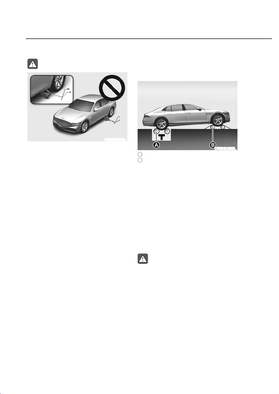
6-42
Driving Your Vehicle
WARNING
ORS061054L
Never start or run the engine while
an AWD vehicle is raised on a jack.
The vehicle can slip or roll off of a jack
causing serious injury or death to you or
those nearby.
Towing
AWD vehicles must be towed with
a wheel lift and dollies or flatbed
equipment with all the wheels off
the ground. For more details, refer to
"Towing" section in chapter 8.
Vehicle inspection
ȉ If the vehicle needs to be operated on
a vehicle lift do not attempt to stop
any of the four wheels from turning.
This could damage the AWD system.
ȉ Never engage the parking brake while
running the engine on a car lift. This
may damage the AWD system.
Dynamometer testing
An AWD vehicle must be tested on a
special four wheel chassis dynamometer.
ORS061055L
A
: Roll tester (Speedometer),
B
: Temporary free roller
An AWD vehicle should not be tested
on a 2WD roll tester. If a 2WD roll tester
must be used, perform the following
procedure:
1. Check the tire pressures
recommended for your vehicle.
2. Place the rear wheels on the roll tester
for a speedometer test as shown in
the illustration.
3. Release the parking brake.
4. Place the front wheels on the
temporary free roller as shown in the
illustration.
WARNING
Keep away from the front of the vehicle
while the vehicle is in gear on the
dynamometer. The vehicle can jump
forward and cause serious injury or
death.
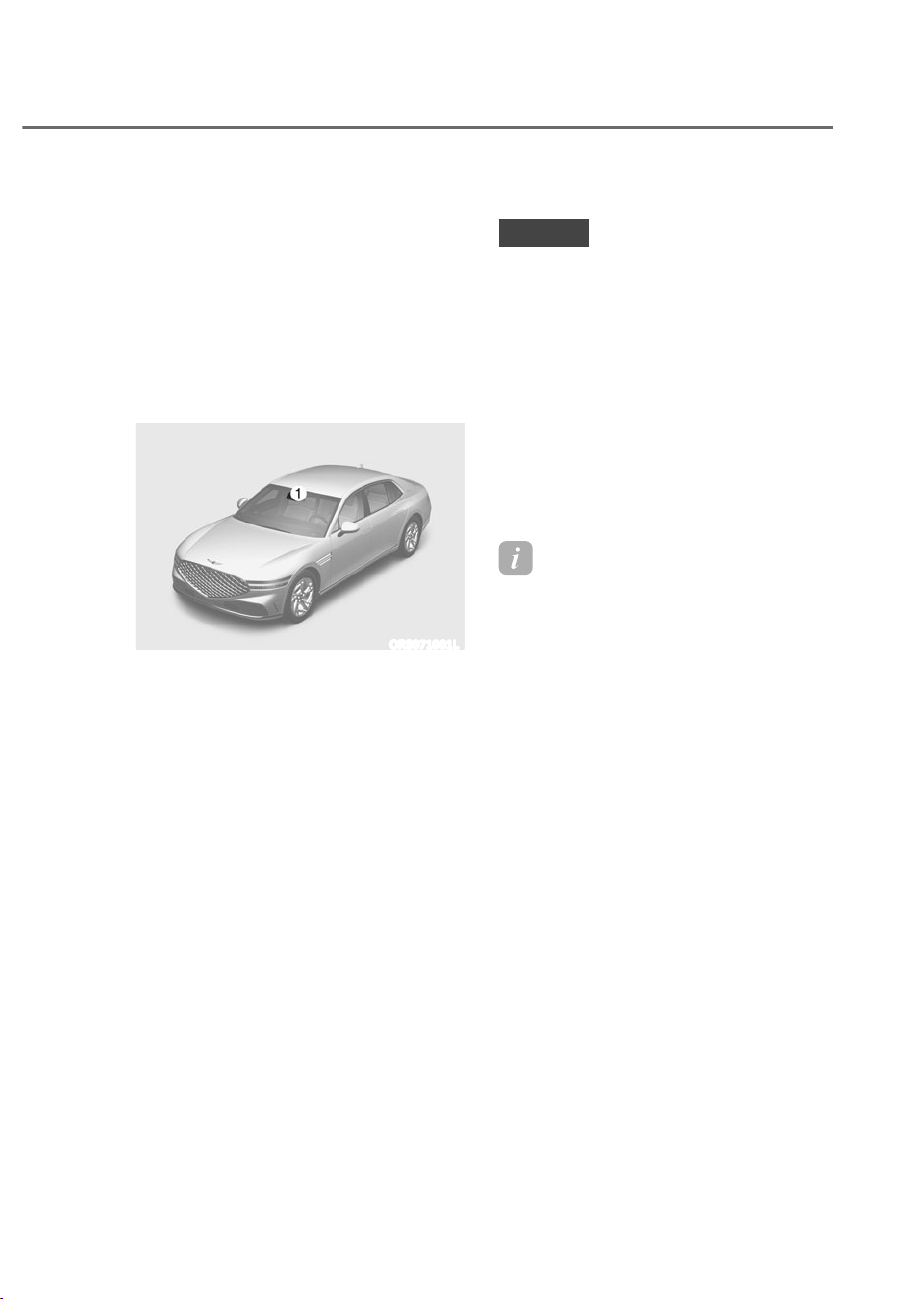
6-43
06
Electronically Controlled Suspension
with Road Preview controls the vehicle
suspension automatically using the front
view camera and vehicle sensors to
maximize driving comfort by taking into
account the driving conditions such as
speed, surface of the road, cornering,
stopping requirements and acceleration.
Front view camera
ORS071001L
M: Front view camera
The front view camera is a sensor that
detects the front road. If the windshield
or the front view camera is covered
with snow, rain or foreign matters, the
data collected by the camera is limited
due to the degradation of the camera’s
performance. Always keep the front view
camera clean.
NOTICE
ȉ NEVER install any accessories or
stickers on the front windshield, or
tint the front windshield.
ȉ NEVER place any reflective objects
(for example, white paper, mirror)
over the dashboard. Any light
reflection may prevent the system
from functioning properly.
ȉ Pay extreme caution to keep the
camera dry.
ȉ Never disassemble the camera
assembly, or apply any impact on the
camera assembly.
Information
Have the system inspected by an
authorized retailer of Genesis Branded
products when:
ȉ The windshield glass is replaced.
ȉ The front view camera or cover gets
damaged or replaced.
ELECTRONICALLY CONTROLLED SUSPENSION WITH ROAD
35(9,(:ʚ,)(48,33('ʛ

6-44
Driving Your Vehicle
System Malfunction
OJWEV061048L
heck Electronic Suspension
When Electronically Controlled
Suspension with Road Preview is not
working properly, this warning message
will appear on the cluster LCD display. If
this occurs, have the system inspected
by an authorized retailer of Genesis
Branded products.
NOTICE
If the battery level is high or low,
Electronically Controlled Suspension
with Road Preview may not work
temporarily to protect the system. If this
occurs, ‘Check Electronic Suspension’
warning message will appear.
Limitations of the System
Electronically Controlled Suspension
with Road Preview always operates
while driving according to the vehicle’s
movement, and the preview function
starts to work when the front view
camera detects road conditions such as
speed bumps. Therefore, the preview
function is limited when there is an
extreme condition that the front view
camera may not work normally. In this
case, the electronic control suspension
function operates without the preview
function in accordance with vehicle
movement.
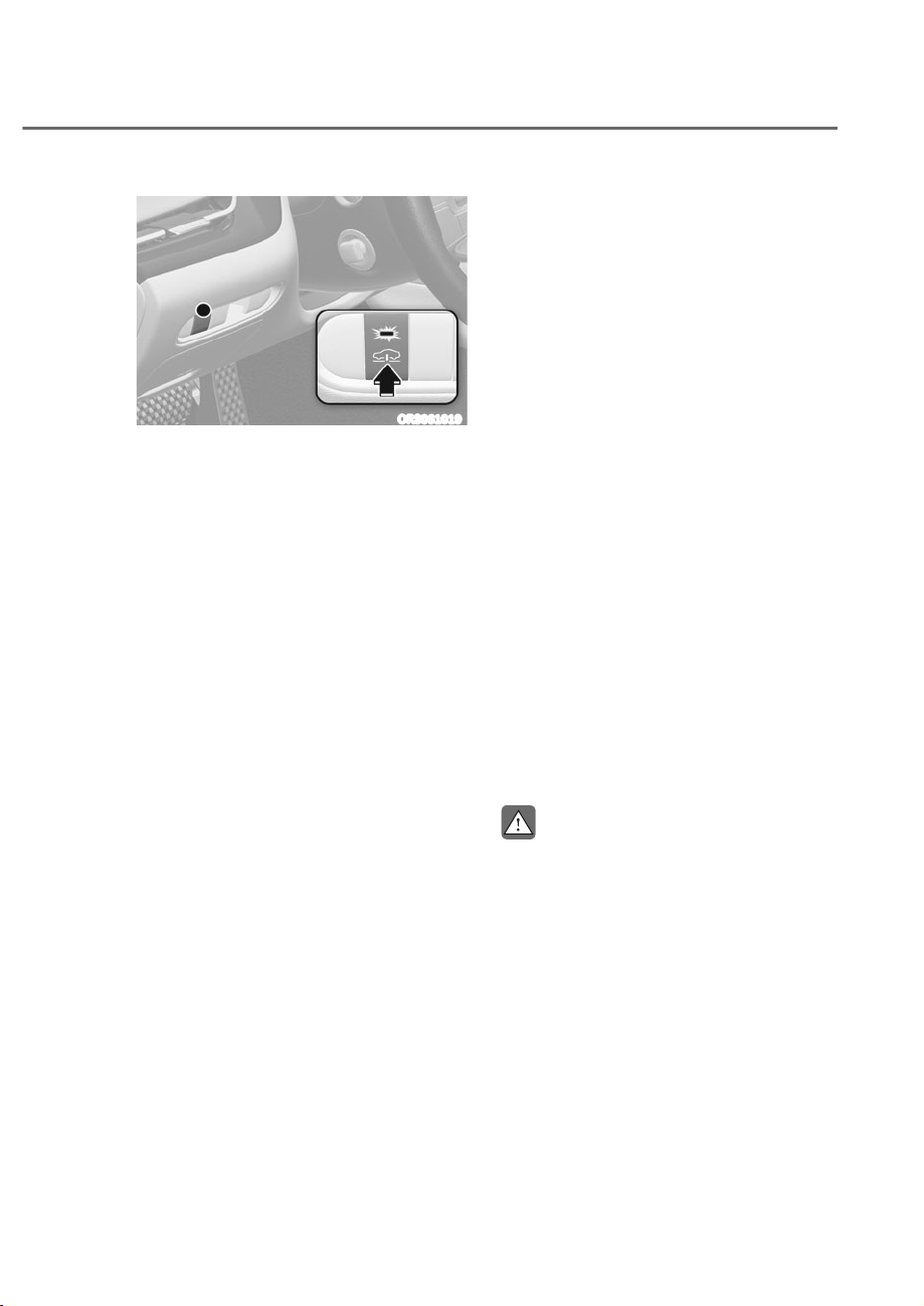
6-45
06
ORS061019
The Multi-chamber air suspension uses
the air spring containing compressed
air to adjust and maintain the vertical
height of the vehicle both manually or
automatically, according to number of
passengers and load capacity. It also
controls the valve inside the air spring
to adjust stiffness of the air spring and
damper to maximize driving comforts.
Each driving mode provides different
ride comforts.
Vehicle Height Adjustment
ȉ Press the vehicle height adjustment
button to adjust the height. Pressing
the button will raise the vehicle body
and the indicator light illuminates.
Pressing the button again will return
the vehicle height to its original
position and the indicator light turns
off.
ȉ If the vehicle is driving in high speed,
the vehicle height adjustment is set
to automatic mode and the vehicle
height will return to its original
position although you press the
button.
- While above a certain speed, the
height will be automatically set
depending on the driving speed.
- Vehicle height may differ depending
on the drive mode.
ȉ Depending on vehicle condition,
height adjustment will not operate or
stop operating, and the indicator light
blinks.
- When the Multi-chamber air
suspension is malfunctioning
- When the vehicle is lifted up.
- When the vehicle is not stable due
to a sudden brake or acceleration.
- When the air compressor is
overheated.
- When the vehicle is not parked on a
level ground.
ȉ Vehicle height may automatically be
adjusted after 2/4/8/16 hours from
turning off the engine. It is due to the
changes in air temperature.
CAUTION
If the compressor air filter under the
vehicle body is submerged in water,
do not operate the air suspension.
Moisture inflow may damage the
system.
08/7,ʏ&+$0%(5$,56863(16,21ʚ,)(48,33('ʛ

6-46
Driving Your Vehicle
Multi-Chamber Air Suspension
Malfunction
OJWEV061048L
This message is displayed when there is
a malfunction with the Multi-chamber
air suspension system. Have the vehicle
inspected by an authorized retailer of
Genesis Branded products.
CAUTION
ȉ When adjusting vehicle height, check
if there are any obstacles below or
above the vehicle.
ȉ If air inside the suspension is
discharged, a warning message
will be displayed. If so, stop driving
and use a towing vehicle. Since
the vehicle height will be very low,
projections on the road may damage
the vehicle. See ‘Towing when the
air suspension malfunctions’ before
towing the vehicle.
Information
ȉ perating the air suspension may
cause a little noise when charging and
discharging the air.
ȉ Ad usted vehicle height may vary
depending on the temperature and
surrounding environment.
ȉ When the suspension warning message
is displayed, the system enables safe
mode to prevent secondary failure
and the vehicle performance may be
displayed differently.
ȉ When the vehicle is parked on a slope,
or when the vehicle is in unstable
condition due to sudden acceleration,
deceleration or steering, vehicle height
ad ustment becomes temporarily
disabled. If the vehicle escapes from
such dangerous situation, vehicle height
ad ustment is enabled again.
ȉ When the vehicle is lifted up with a
lift or ack, height ad ustment may be
disabled to protect the system. If the
vehicle engine is started or you start
driving, the function is enabled again.
ȉ Leaving the vehicle parked for long
time may lower the vehicle height. The
vehicle height returns to its original
position when the engine is started.
ȉ If the battery is either overcharged or
discharged, vehicle height ad ustment
is disabled to protect the system and a
temporary warning message may be
displayed.
ȉ If the vehicle height ad ustment is
operated repeatedly, the function may
be temporarily disabled due to the
overheated compressor. It is to prevent
the breakdown of related parts.
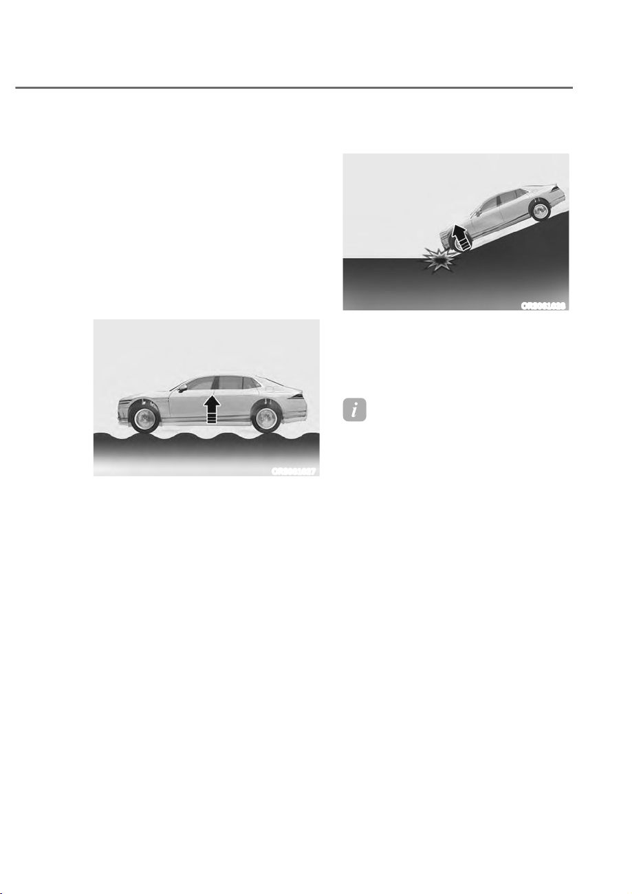
6-47
06
Additional Height Adjustment
Function
Multi-chamber air suspension recognizes
the driving condition to automatically
adjust vehicle height, spring stiffness,
and shock absorber damping force for
driving comfort and vehicle protection.
Additional vehicle height adjustment
operates automatically depending
on various conditions and it is not
necessarily displayed to the driver.
Off road driving
ORS061027
The vehicle adjusts vehicle height, spring
stiffness, and shock absorber damping
force when driving on a rough terrain
such as an unpaved road, to optimize
comfort and protect the vehicle.
Driving on a slope
ORS061028
The vehicle adjusts vehicle height, spring
stiffness, and shock absorber damping
force when driving over a steep slope,
to optimize comfort and protect the
vehicle.
Information
ȉ Additional vehicle height ad ustment
function operates differently
depending on various driving and
system conditions. In some cases, its
operability and actuation speed may
vary.
ȉ When the vehicle speed is below 6 mph
(10 km/h) or above 37 mph (60 km/h),
the safety bump driving function may
be disabled.
ȉ When the vehicle speed is above 18
mph (30 km/h), the off road driving
and slope driving function may be
disabled.
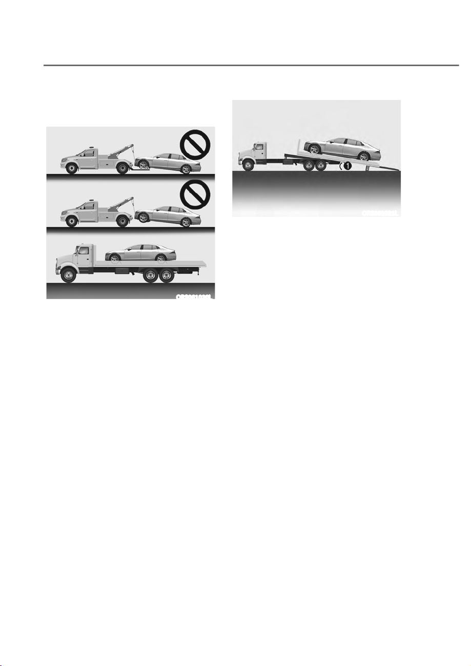
6-48
Driving Your Vehicle
Towing When the Air Suspension
Malfunction
ORS061020L
Driving while the suspension is
malfunctioning and the air inside the
suspension is discharged may damage
the vehicle.
Use the towing vehicle and we
recommend that you have the system
checked by an authorized retailer of
Genesis Branded products.
Use only flatbed tow trucks. Other
towing methods may damage the
vehicle.
ORS061021L
The flatbed tow truck must be a safety
loader type which has a loading angle M
less than 6º.
Towing with a loading angle larger than
6º may damage the vehicle.
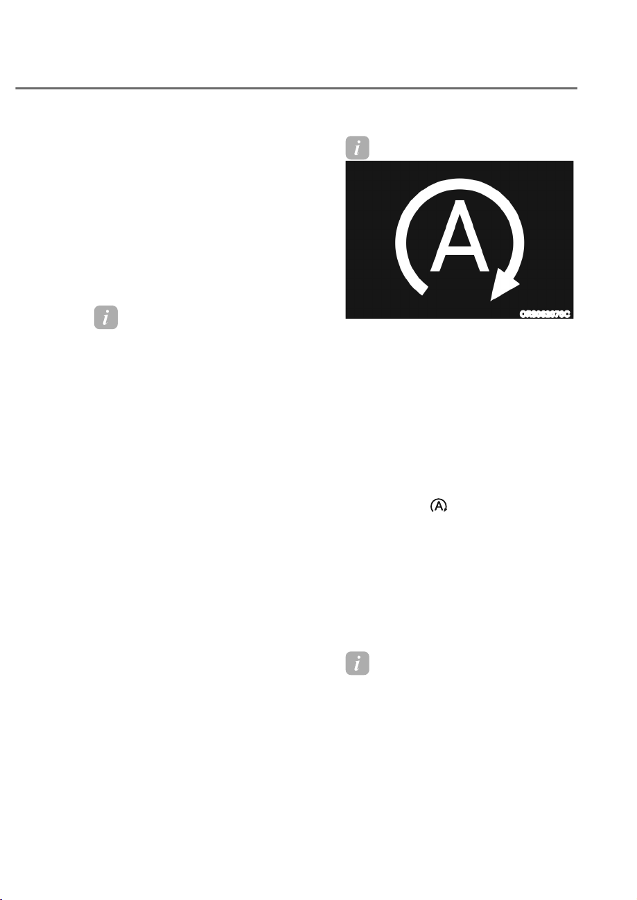
6-49
06
Idle Stop and Go helps reduce fuel
consumption by automatically shutting
down the engine, when the vehicle is
at a standstill (for example, red stop
light, stop sign, and traffic jam) subject
to certain prerequisite conditions being
satisfied as listed below.
The engine is automatically started upon
satisfying the starting conditions.
ISG system is always active, when the
engine is running.
Information
When the engine is automatically started
by ISG system, warning lights (for
example, ABS, ES , ES FF, MDPS,
and parking brake warning light) may
illuminate for a few seconds due to low
battery voltage.
However, it does not indicate a
malfunction with ISG system.
ISG System Operation
Prerequisite for activation
ISG system operates in the following
situations.
ȉ The driver's seatbelt is fastened
ȉ The driver's door and hood are closed
ȉ The battery sensor is activated and
the battery is sufficiently charged
ȉ Outside temperature is not too low or
too high
ȉ The vehicle is driven over a constant
speed and stops
ȉ The climate control system satisfies
the conditions
ȉ The vehicle is sufficiently warmed up
ȉ ISG related parts are working properly
ȉ The incline is gradual
ȉ The steering wheel is turned less than
180 degrees and then the vehicle
stops
Information
ORS062070C
ISG system is not activated, when the
prerequisites to activate the ISG system
are unsatisfied.
Auto stop
When ISG is on the engine will be
stopped automatically when both of the
following occurs:
1. Vehicle speed decreases to 0mph (0
km/h) full stop condition.
2. Brake pedal is depressed and gear is
in D (Drive) or N (Neutral).
The Auto Stop (
) indicator illuminates
in green on the instrument cluster, when
the engine stops.
The gasoline 3.5 turbo 48 V electric
supercharger vehicle may automatically
shut down the engine when the vehicle
speed is below 16 mph (25 km/h) with
the brake pedal depressed. At this time,
the ISG indicator lights up in green on
the instrument cluster.
Information
Idle stop cannot reoccur again until the
vehicle speed goes above 3 mph (5 km/h)
and then returns again to the automatic
stop conditions as previously mentioned.
,'/(6723$1'*2ʚ,6*ʛʚ,)(48,33('ʛ
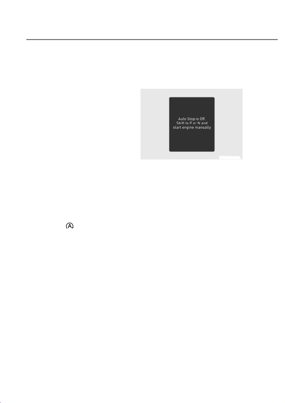
6-50
Driving Your Vehicle
In the Auto Stop mode, if the engine
hood is opened, ISG system will be
deactivated.
When the system is deactivated, a
message ‘Auto Stop is off. Shift to P or
N to start engine manually’ appears on
the cluster LCD display with a warning
sound.
If this occurs, depress the brake pedal
and restart the engine manually.
Auto start
When the engine stops automatically by
ISG, the engine will restart if one of the
following is done.
- Release the brake pedal.
- When Auto Hold is activated, take
your foot off the brake pedal and then
depress the accelerator pedal.
- While depressing the brake pedal,
shift the gear from N (Neutral) or D
(Drive) to R (Reverse) or P (Park).
- While depressing the brake pedal,
shift the gear from N (Neutral) to D
(Drive).
The Auto Stop (
) indicator turns into
white on the instrument cluster, when
the engine is restarted.
LCD display messages
The messages are displayed on the
instrument cluster to help use ISG
system.
ORS061032L
Auto Stop is ff. Shift to P or N and start
engine manually
When the system is deactivated, a
message will appear on the cluster LCD
display with a warning sound in the
following situations.
- When the engine hood is opened.
- When ISG system is not working
normally.
If this occurs, depress the brake pedal
and restart the engine manually. For your
safety, restart the vehicle in the P (Park)
position.
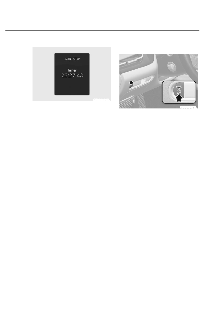
6-51
06
ORS061049L
AUT ST P elapsed time
AUTO STOP display shows the elapsed
time of engine stop by the Idle Stop and
Go system.
You may check AUTO STOP elapsed time
in the Normal view on the instrument
cluster.
Refer to “View Modes” section in chapter
4.
ISG System Off
ORS061022L
Press the ISG OFF button to turn off ISG
system. The ISG OFF button indicator will
illuminate. To use the system, press the
ISG OFF button again.

6-52
Driving Your Vehicle
Forced to Restart Engine
The engine is automatically restarted in
the following situations.
ȉ The engine has stopped for about 5
minutes
ȉ The air conditioning is ON with the fan
speed set to a certain high level
ȉ The front defroster is ON
ȉ The battery is weak
ȉ The cooling and heating performance
of the climate control system is
unsatisfactory
ȉ The vehicle is shifted to P (Park), N
(Neutral) or R (Reverse) when Auto
Hold is operating
ȉ The door is opened or the seatbelt
is unfastened when Auto Hold is
activated
ȉ The EPB switch is pressed when Auto
Hold is activated
The Auto Stop (
) indicator blinks in
green for 5 seconds on the instrument
cluster when the engine is restarted.
WARNING
When the engine is in Idle Stop mode,
the engine may restart without the
driver taking any action. Before leaving
the vehicle or working on the engine
compartment, turn off the engine by
pressing the ENGINE START/STOP
button to the OFF position.
ISG Malfunction
ISG system may not operate when there
is a malfunction with the ISG sensors or
ISG system.
The following will occur, when there is a
malfunction with the ISG system:
ȉ The Auto Stop (
) indicator will
illuminate in yellow on the instrument
cluster.
Contact an authorized retailer of Genesis
Branded products.
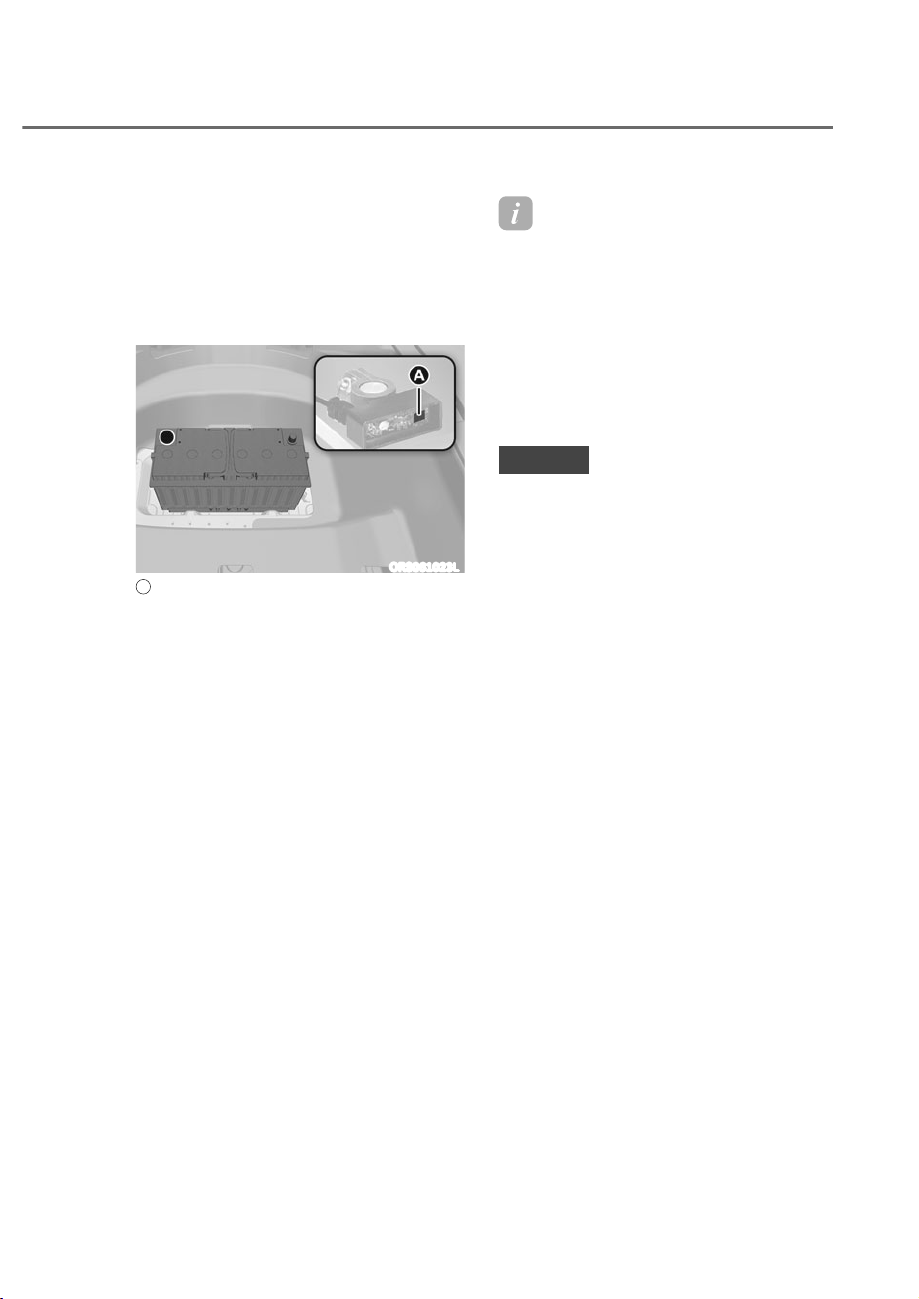
6-53
06
Calibrating the Battery Sensor
If the AGM battery is reconnected or
replaced, ISG system will not operate
immediately. If you want to use the
system, the battery sensor needs to
be calibrated following the below
procedure.
ORS061023L
A
: Battery sensor
1. Turn off the engine.
2. Disconnect all electronic devices
that were additionally installed after
the vehicle was delivered, such as
navigation, dashcam, etc.
3. After 4 hours with the engine off, turn
the engine on and off 3 to 4 times.
Information
The ISG system may not operate in the
following situations.
- There is a malfunction with the ISG
system.
- The battery is weak.
- The brake vacuum pressure is low.
If this occurs, have the ISG system
checked by an authorized retailer of
Genesis Branded products.
NOTICE
ȉ Use only a genuine Genesis ISG
battery for replacement. If not,
the ISG system may not properly
operate.
ȉ Do not recharge the ISG battery with
a general battery charger. It may
damage or explode the ISG battery.
ȉ Do not remove the battery cap. The
battery electrolyte, which is harmful
to the human body, may leak out.
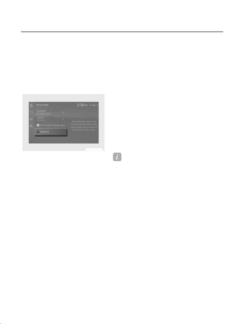
6-54
Driving Your Vehicle
&2$67,1*ʚ,)(48,33('ʛ
When certain conditions are met, the
engine is automatically decoupled from
the transmission while gear remains in D
(Drive). When Coasting is operating, the
engine stays at idling speed to reduce
fuel consumption and increase coasting
distance.
Coasting Setting
ORS061033L
ȉ The Coasting function must be turned
ON from the Settings menu in the
infotainment system screen. Select:
- 6HWXSɌ9HKLFOHɌ'ULYH0RGHɌ
Coasting
See additional information in supplied
Infotainment Manual.
ȉ When Coasting is turned ON and
the conditions are met, the function
operates with a ‘Coasting’ message
illuminated on the instrument cluster.
Coasting Operating Conditions
The Coasting function will operate when
the accelerator pedal is depressed and
released under the following conditions.
ȉ ECO is selected for driving mode
ȉ ECO or Smart is selected for
Powertrain in the CUSTOM menu from
the infotainment system screen. If
Smart is selected, driver acceleration
should be mild
ȉ The gear is in D (Drive)
ȉ Smart Cruise Control is OFF
ȉ The accelerator or brake pedal is not
depressed
ȉ The vehicle’s speed is within 30~100
mph (50~160 km/h) range
ȉ The road gradient is within -5~+5%
range
Information
ȉ If the front radar for Smart ruise
ontrol cannot operate normally, the
inter-vehicle distance and relative speed
condition are automatically ignored.
ȉ The oasting function works after the
engine is turned on, the transmission is
warmed up, and the engine sensor self-
diagnosis is completed.
ȉ Depending on the driving situation,
oasting operation may be temporarily
delayed even if the above conditions are
met.

6-55
06
Coasting Release Conditions
The Coasting function will be
automatically released when the
following conditions are met.
ȉ Comfort or Sport is selected for
driving mode
ȉ The driver uses the paddle shifter
ȉ Smart Cruise Control is activated (Set
speed appears on the cluster)
ȉ The vehicle’s speed exceeds 30~100
mph (50~160 km/h) range
ȉ The road gradient is under -5% or over
+5%
ȉ If the distance between the vehicle
ahead is too close or the relative
speed changes momentarily in Smart
mode
ȉ If lane change is predicated in Smart
mode (for example, the turn signal is
turned ON or a LKA warning appears
due to steering wheel control, etc.)
Information
It is recommended to turn off the
oasting function if you are driving under
frequently stop-and-go condition. hange
the drive mode to omfort or Sport or
deselect oasting from the infotainment
system screen.
NOTICE
ȉ If the accelerator pedal is pressed
quickly for accelerating with the
Coasting function in operation,
acceleration may occur after the
engagement of the clutch inside the
transmission. In turn, the driver may
continue to feel acceleration even
after the system is turned off.
ȉ Driving with the Coasting function
off may be required in some cases
since the engine brake is not applied
while the Coasting function is
operating.
ȉ Operating the infotainment system
screen to activate or deactivate
the Coasting function while driving
may be dangerous as the driver’s
attention is dispersed.

6-56
Driving Your Vehicle
Predictive shift feature proactively
upshifts or downshifts the gear based on
the data detected from the navigation,
front radar sensor, and camera.
CAUTION
Predictive shift is a convenience
feature. Regardless of its operation,
the driver must pay attention to
the road condition and abide traffic
laws. The vehicle manufacturer
does not take any responsibility for
traffic law violation and accidents.
Predictive shift Operating
Conditions
Predictive shift operates when it is in
the ready state, and a specific situation
is detected while driving. Details
on prerequisites for activation and
operations are as follows.
ȉ Prerequisites for activation: Predictive
shift operates when all the following
conditions are met.
- Drive mode is set to SMART
- Gear is positioned in D (Drive)
- Smart cruise control is off
- Engine and transmission operate
normally
- Front radar sensor and related
controllers operate normally
- When driving on a highway
ȉ Operating condition:
Predictive shift function operates
when one of the following situation is
detected.
- Curve or downhill ahead
- Roundabout ahead
- Entering highway
- Low speed vehicle ahead (Vehicle-
to-vehicle distance is closing in)
Predictive shift off Conditions
The predictive shift function will be
released when the following conditions
are met.
- The detected situation is over
- Drive mode is shifted from SMART to
another mode
- Gear is shifted from D (Drive) to
another gear position
- Paddle shifter is used
- Smart cruise control is on
- Engine or transmission malfunctions
- Front radar sensor or related
controllers malfunction
35(',&7,9(6+,)7ʚ,)(48,33('ʛ
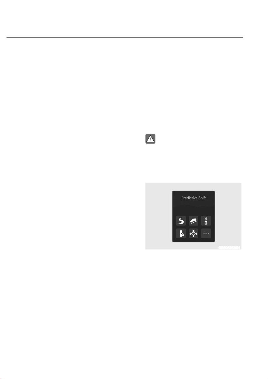
6-57
06
Limitations of the System
The predictive shift may have limited
operation in the following situations
ȉ If you do not take the route guided in
the navigation, predictive shift may
not operate properly since the system
operates according to the navigated
route. Predictive shift will operate
properly again once the navigation
sets a new route.
ȉ The navigation may reflect the real
time traffic condition and change the
route. If so, the predictive shift may
not correspond temporarily to the
current driving condition.
ȉ If the destination is not set on the
navigation, predictive shift operates
according to the route which is most
likely to be taken. When driving
through roads such as a branch road,
predictive shift may not correspond to
the current driving condition until the
navigation sets a new route.
ȉ While using the navigation app
through smart phone linked functions
such as Android Auto or Apple
CarPlay, predictive shift operates as
when the destination is not set in the
vehicle’s navigation.
ȉ Predictive shift may not operate
properly in the following situations.
- Navigation system is not completely
booted.
- Real time GPS or map data has
errors, or the map data is not up to
date.
Checking Operation on the
Instrument Cluster
The operating condition of predictive
shift can be checked from the icons and
messages displayed on the instrument
cluster. If there are multiple conditions
detected, every related icon illuminates
but only the most important message
is displayed. The images and colors
of the messages may differ from the
description depending on the cluster
type.
CAUTION
Always be aware of the traffic and
road condition ahead. Checking the
instrument cluster while driving
may cause an accident.
When predictive shift is ready
ORS062039N
Refer to the following for icons displayed
when predictive shift is stand-by for use.
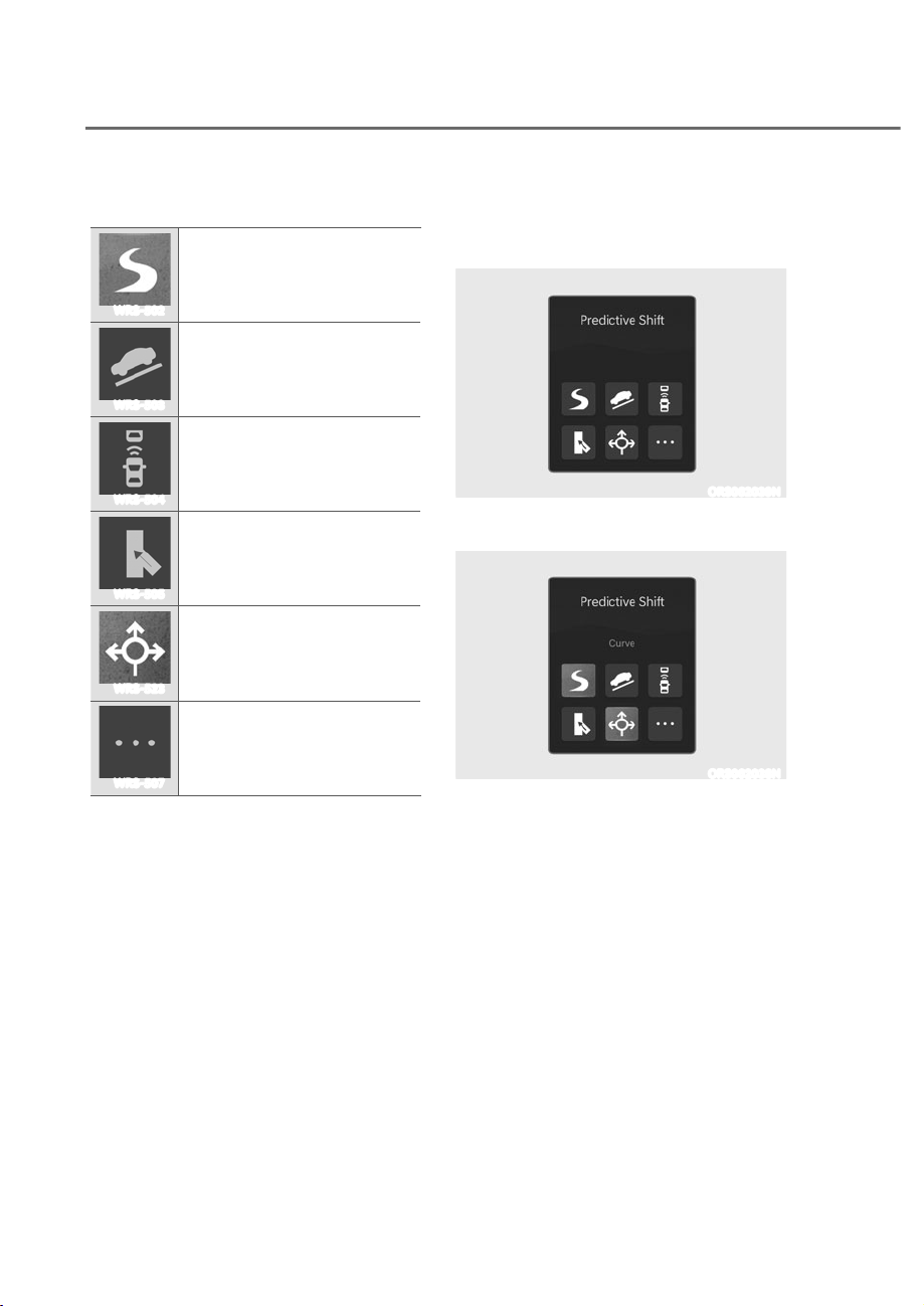
6-58
Driving Your Vehicle
Icons
WRS-502
Entering curve
WRS-503
Entering downhill
WRS-504
Approaching to vehicle ahead
WRS-505
Entering highway
WRS-523
Roundabout detected
WRS-507
Other situations detected
While predictive shift is on
ȉ When shifting the gear by detecting
forward road condition
ORS062039N
ȉ When shifting the gear by detecting
multiple conditions ahead
ORS062038N
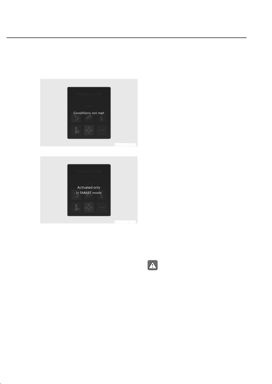
6-59
06
When predictive shift is off
ȉ When the system does not meet the
operating conditions.
ORS062041N
ȉ When the drive mode is not in SMART.
ORS062042N
How Predictive Shift Operates
Predictive shift operates according to the
detected conditions.
Predictive shift in curve
If there is a curve ahead, the gear is
downshifted in advance to engage the
engine brake automatically. After passing
the curve, it will help the vehicle to
reaccelerate.
- If you drive smoothly through a curve,
or if the curve is gradual, predictive
shift does not operate.
- Predictive shift may operate if there is
a sharp curve, or the vehicle speed is
high when entering a highway ramp or
turning left or right on a crossroad.
Predictive shift to maintain speed
during downhill coasting
When coasting on a downhill, the engine
brake is automatically engaged to help
maintain the vehicle speed.
- If the slope is gentle or short,
predictive shift does not operate.
- If the downhill slope is steep, the
engine brake may be strongly
engaged to maintain speed.
- Depressing the brake or accelerator
pedal while predictive shift is being
activated will temporarily disable the
function.
CAUTION
Predictive shift to maintain speed
during downhill coasting is only to
assist the driver to drive safely on
a downhill. It does not accelerate
or decelerate the vehicle. If
acceleration or deceleration is
required, depress the pedal to
manually adjust the speed.

6-60
Driving Your Vehicle
Predictive shift in roundabout
If there is a roundabout ahead, the
predictive shift downshifts the gear
before entering the roundabout to assist
the driver to go through the roundabout
smoothly and reaccelerate the vehicle.
Predictive shift to accelerate when
entering highways (Interchange/ unction)
When entering the main road of
highways, the drive mode is temporarily
changed to SMART SPORT at the
interchange or junction to assist the
vehicle to accelerate easily.
- It also operates when entering an
expressway.
- While the SMART SPORT mode is
on, the red ‘SMART’ message will
illuminate on the instrument cluster.
- The drive mode will revert back to
SMART ECO or SMART COMFORT
when the vehicle has completely
entered the highways.
- Predictive shift operates only when
the vehicle is accelerated sufficiently
at the highways interchange or
junction to enter the main road. It
does not operate if the vehicle speed
is low.
- When entering the highways ramp
with the vehicle in SMART ECO mode,
the drive mode will automatically
change to SMART COMFORT. The
white ‘SMART’ message will illuminate
on the cluster.
- When predictive shift is operating, the
acceleration performance is equal to
that of when SPORT mode is selected
by pressing the drive mode button.
Predictive shift when approaching a
vehicle ahead
If the speed of the vehicle ahead is low
and the distance is getting closer, the
engine brake is engaged automatically to
assist in deceleration.
- When the vehicle reaches an
appropriate distance and the speed is
equal to the vehicle ahead, predictive
shift will be finished.
- If the brake or accelerator pedal
is depressed while predictive shift
is operating, the function will be
temporarily disabled.
- If there is a large difference of speed
from the vehicle ahead, the engine
brake may be engaged greatly to
obtain appropriate vehicle-to-vehicle
distance.
CAUTION
‘Predictive Shift when Approaching
to Vehicle Ahead’ is a function to
assist deceleration by detecting
the speed difference with the
vehicle ahead and does not directly
prevent collision. If the vehicle
ahead abruptly decelerates and
the distance rapidly decreases, the
driver must depress the brake pedal
to decelerate.
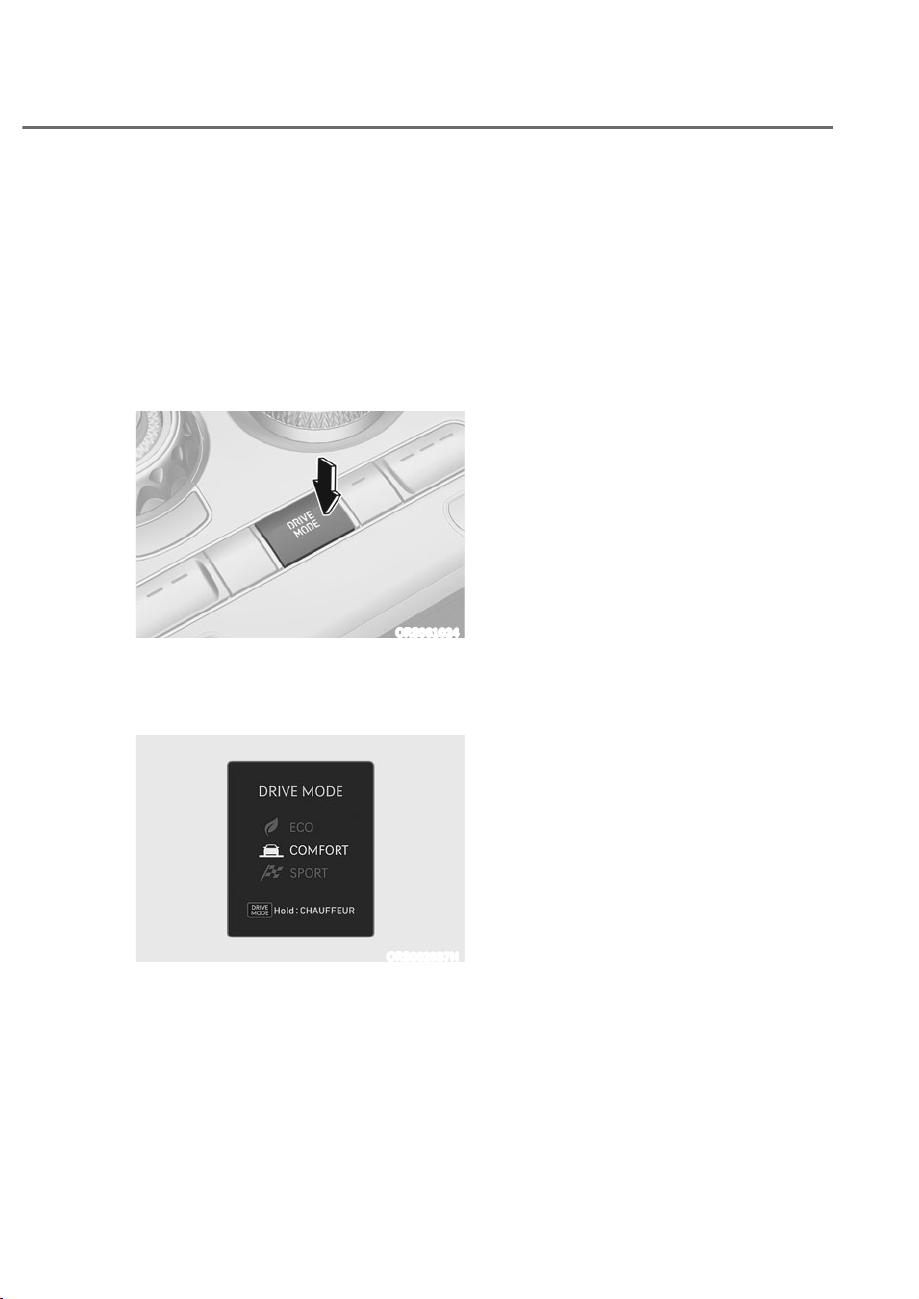
6-61
06
Selecting Drive Mode
Drive mode may be selected according
to the driver's preference or road
condition.
Changing drive mode (ECO,
COMFORT, SPORT)
Shortly press the DRIVE MODE button
to change among ECO, COMFORT and
SPORT.
ORS061024
The drive mode changes as below
whenever the DRIVE MODE button is
pressed.
- (&2Ɍ&20)257Ɍ63257
ORS062037N
Switching to CUSTOM mode
Press and hold the DRIVE MODE button
to change to CUSTOM mode. The drive
mode will shift from ECO, COMFORT,
SPORT mode and then switch to pre-
selected CUSTOM mode.
- (&2Ɍ&20)257Ɍ63257Ɍ3UH
selected CUSTOM mode
To select a CUSTOM mode, go to ‘Setup
Ɍ9HKLFOHɌ'ULYH0RGHɌ&86720ȂLQWKH
infotainment system.
- SMART
- CHAUFFEUR
- MY DRIVE
Setting BRAKE mode
To set the BRAKE mode to adjust brake
response, park the vehicle and shift the
JHDUWR33DUN*RWR6HWXSɌ9HKLFOHɌ
'ULYH0RGHɌ%UDNHVȂLQWKHLQIRWDLQPHQW
system and select a mode.
- COMFORT: Brake response
appropriate for comfort driving.
- SPORT: Brake response appropriate
for dynamic driving.
- CHAUFFEUR: Brake response
appropriate for rear seat comfort.
DRIVE MODE INTEGRATED CONTROL SYSTEM

6-62
Driving Your Vehicle
ECO, COMFORT, SPORT Mode
Features
ECO mode (if equipped)
ECO mode helps improve fuel
efficiency for eco-friendly
driving.
Fuel efficiency varies according
to the driver's driving habit and
road condition.
ȉ When ECO mode is selected, the
ECO indicator will illuminate on the
instrument cluster.
ȉ When ECO mode is activated:
- The acceleration response may be
slightly reduced if the accelerator
pedal is depressed moderately.
- The air conditioner performance
may be limited.
- The shift pattern of the automatic
transmission may change.
- Engine noise may be louder at some
automatic transmission shifts as
down-shift requires pressing down
more on the accelerator.
The above situations are normal
conditions when ECO mode is activated
to help improve fuel efficiency.
COMFORT mode
COMFORT mode provides smooth
driving and comfortable riding.
SPORT mode
SPORT mode provides sporty
but firm riding.
In SPORT mode, the fuel
efficiency may decrease.
ȉ When SPORT mode is selected, the
SPORT indicator will illuminate on the
instrument cluster.
ȉ Whenever the engine is restarted,
the drive mode will revert back to
COMFORT mode. If SPORT mode is
desired, re-select SPORT mode.
ȉ When SPORT mode is activated:
- The engine RPM will tend to remain
raised over a certain length of time
even after releasing the accelerator
- Upshifts are delayed when
accelerating
NOTICE
In the SPORT mode, the fuel efficiency
may decrease.

6-63
06
CUSTOM Mode Features
SMART mode
SMART mode selects the proper driving
mode among SMART ECO, SMART
COMFORT and SMART SPORT by judging
the driver's driving habits (for example,
mild or dynamic) from the brake pedal
depression or the steering wheel
operation.
arious driving situations, which you may
encounter in SMART mode
ȉ The driving mode automatically
changes to ECO mode after a certain
period of time, when you gently
depress the accelerator pedal (Your
driving is categorized to be mild.).
ȉ The driving mode automatically
changes from SMART ECO mode
to SMART COMFORT mode after a
certain period of time, when you
sharply or repetitively depress the
accelerator pedal.
ȉ The driving mode automatically
changes to SMART COMFORT mode
with the same driving patterns, when
the vehicle starts to drive on an
upward slope of a certain angle. The
driving mode automatically returns to
SMART ECO mode, when the vehicle
enters a leveled road.
ȉ The driving mode automatically
changes to SMART SPORT mode
only in harsh driving situations. In
most of the normal driving situations,
the driving mode sets to be either
in SMART ECO mode or in SMART
COMFORT mode.
ȉ The driving mode automatically
changes to SMART SPORT, when
you abruptly accelerate the vehicle
or repetitively operate the steering
wheel (Your driving is categorized
to be sporty.). In this mode, your
vehicle drives in a lower gear for
abrupt accelerating or decelerating
and increases the engine brake
performance.
For general description of SMART ECO,
SMART COMFORT, and SMART SPORT
modes, refer to “ECO, COMFORT, SPORT
mode features”.

6-64
Driving Your Vehicle
Limitation of SMART mode
SMART may be limited in following
situations. ECO, COMFORT, SPORT mode
features
ȉ The driver is using the paddle shifter
to manually shift gear. (The system
prioritizes the driver’s manual shifting)
ȉ Smart Cruise Control is activated.
ȉ The transmission oil temperature is
either extremely low or extremely
high.
Information
ȉ When you mildly drive the vehicle
in SMART mode, the driving mode
changes to E mode to improve fuel
efficiency. However, the actual fuel
efficiency may differ depending on your
driving situations such as slope angle,
and vehicle speed.
ȉ When you dynamically drive the
vehicle in SMART mode by abruptly
decelerating or sharply curving, the
driving mode changes to SP RT mode.
However, it may adversely affect fuel
economy.
CHAUFFEUR mode
CHAUFFEUR mode controls the
suspension, engine, transmission, and
steering wheel to provide comfort driving
experience to rear seat passengers.
MY DRIVE MODE
MY DRIVE mode will allow the driver to
personalize the setting of the powertrain,
steering wheel, suspension, and AWD.
7RVHW0<'5,9(PRGHJRWRȁ6HWXSɌ
9HKLFOHɌ'ULYH0RGHɌ&86720Ɍ0<
DRIVE’ in the infotainment system.
- Powertrain: ECO/COMFORT/SPORT
- Steering: COMFORT/SPORT
- Suspension: COMFORT/SPORT
- AWD (if equipped): ECO/COMFORT/
SPORT

6-65
06
Road Active Noise Control helps reduce
noise caused while driving.
The system may not operate properly in
the following conditions:
ȉ Any of the window is open
ȉ Any of the door is open
ȉ The sunroof is open
ȉ The trunk is open
ȉ Vehicle’s microphone and speaker is
blocked by loads
NOTICE
If high temperature or high pressure
steam is sprayed on the microphone, it
may malfunction.
ROAD ACTIVE NOISE
&21752/ʚ,)(48,33('ʛ
ACTIVE SOUND DESIGN
ʚ,)(48,33('ʛ
ȉ Active Sound Design is a function
that provides enhanced virtual engine
sound when the driver is depressing
the accelerator pedal.
ȉ You can activate or deactivate Active
Sound Design function from the
Settings menu in the infotainment
system screen. Select:
- 6HWXSɌ9HKLFOHɌ$FWLYH6RXQG
'HVLJQɌ(KDQFHG6WDQGDUG
Minimized/Off, or
- 6HWXSɌ6RXQGɌ$FWLYH6RXQG
'HVLJQɌ(QKDQFHG6WDQGDUG
Minimized/Off
See additional information in supplied
Infotainment Manual.
ȉ Any unauthorized replacement of
the vehicle’s speaker and amplifier
may cause Active Sound Design to
malfunction.

6-66
Driving Your Vehicle
SPECIAL DRIVING CONDITIONS
Hazardous Driving Conditions
When hazardous driving elements
are encountered such as water, snow,
ice, mud and sand, take the following
precautions:
ȉ Drive cautiously and maintain a longer
braking distance.
ȉ Avoid abrupt braking or steering.
ȉ When your vehicle is stuck in
snow, mud, or sand, use second
gear. Accelerate slowly to avoid
unnecessary wheel spin.
ȉ Put sand, rock salt, tire chains or other
non-slip materials under the wheels to
provide additional traction while the
vehicle becomes stuck in ice, snow,
or mud.
WARNING
Downshifting with an automatic
transmission while driving on slippery
surfaces can cause an accident. The
sudden change in tire speed could
cause the tires to skid. Be careful when
downshifting on slippery surfaces.
Rocking the Vehicle
If it is necessary to rock the vehicle to
free it from snow, sand, or mud, first turn
the steering wheel right and left to clear
the area around your front wheels. Then,
shift back and forth between R (Reverse)
and a forward gear.
Try to avoid spinning the wheels, and do
not race the engine.
To prevent transmission wear, wait until
the wheels stop spinning before shifting
gears. Release the accelerator pedal
while shifting, and press lightly on the
accelerator pedal while the transmission
is in gear. Slowly spinning the wheels in
forward and reverse directions causes a
rocking motion that may free the vehicle.
WARNING
If the vehicle is stuck and excessive
wheel spin occurs, the temperature
in the tires can increase very quickly.
If the tires become damaged, a tire
blow out or tire explosion can occur.
This condition is dangerous - you and
others may be injured. Do not attempt
this procedure if people or objects are
anywhere near the vehicle.
If you attempt to free the vehicle, the
vehicle can overheat quickly, possibly
causing an engine compartment fire or
other damage. Try to avoid spinning the
wheels as much as possible to prevent
overheating of either the tires or the
engine. DO NOT allow the vehicle to
spin the wheels above 35 mph
(56 km/h).

6-67
06
Information
The ES system must be turned FF
before rocking the vehicle.
NOTICE
If you are still stuck after rocking the
vehicle a few times, have the vehicle
pulled out by a tow vehicle to avoid
engine overheating, possible damage to
the transmission, and tire damage. See
“Towing” section in chapter 8.
Smooth Cornering
Avoid braking or gear changing in
corners, especially when roads are wet.
Ideally, corners should always be taken
under gentle acceleration.
Driving at Night
Night driving presents more hazards than
driving in the daylight. Here are some
important tips to remember:
ȉ Slow down and keep more distance
between you and other vehicles, as it
may be more difficult to see at night,
especially in areas where there may
not be any street lights.
ȉ Adjust your mirrors to reduce the glare
from other drivers’ headlights.
ȉ Keep your headlights clean and
properly aimed. Dirty or improperly
aimed headlights will make it much
more difficult to see at night.
ȉ Avoid staring directly at the headlights
of oncoming vehicles. You could be
temporarily blinded, and it will take
several seconds for your eyes to
readjust to the darkness.

6-68
Driving Your Vehicle
Driving in the Rain
Rain and wet roads can make driving
dangerous. Here are a few things to
consider when driving in the rain or on
slick pavement:
ȉ Slow down and allow extra following
distance. A heavy rainfall makes
it harder to see and increases the
distance needed to stop your vehicle.
ȉ Turn OFF your Smart Cruise Control
ȉ Replace your windshield wiper blades
when they show signs of streaking or
missing areas on the windshield.
ȉ Be sure your tires have enough tread.
If your tires do not have enough depth
of tire tread, making a quick stop on
wet pavement can cause a skid and
possibly lead to an accident. See “Tire
Tread” section in chapter 9.
ȉ Turn on your headlights to make it
easier for others to see you.
ȉ Driving too fast through large puddles
can affect your brakes. If you must go
through puddles, try to drive through
them slowly.
ȉ If you believe your brakes may be wet,
apply them lightly while driving until
normal braking operation returns.
Hydroplaning
If the road is wet enough and you are
going fast enough, your vehicle may
have little or no contact with the road
surface and actually ride on the water.
The best advice is SLOW DOWN when
the road is wet.
The risk of hydroplaning increases as the
depth of tire tread decreases, refer to
“Tire Tread” section in chapter 9.
Driving in Flooded Areas
Avoid driving through flooded areas
unless you are sure the water is no
higher than the bottom of the wheel hub.
Drive through any water slowly. Allow
adequate stopping distance because
brake performance may be reduced.
After driving through water, dry the
brakes by gently applying them several
times while the vehicle is moving slowly.
Highway Driving
Tires
Adjust the tire inflation, as specified.
Under-inflation may overheat or damage
the tires.
Do not install worn-out or damaged tires,
which may reduce traction or fail the
braking operation.
Information
Never over-inflate your tires above the
maximum inflation pressure, as specified
on your tires.
Fuel, engine coolant and engine oil
Driving at higher speeds on the highway
consumes more fuel and is less efficient
than driving at a slower, more moderate
speed. Maintain a moderate speed in
order to conserve fuel when driving on
the highway.
Be sure to check both the engine coolant
level and the engine oil before driving.
Drive belt
A loose or damaged drive belt may
overheat the engine.

6-69
06
The severe weather conditions of winter
quickly wear out tires and cause other
problems. To minimize winter driving
problems, you should take the following
suggestions:
Snow or Icy Conditions
You need to keep sufficient distance
between your vehicle and the vehicle in
front of you.
Apply the brakes gently. Speeding, rapid
acceleration, sudden brake applications,
and sharp turns are potentially
very hazardous practices. During
deceleration, use engine braking to the
fullest extent. Sudden brake applications
on snowy or icy roads may cause the
vehicle to skid.
To drive your vehicle in deep snow, it
may be necessary to use snow tires or to
install tire chains on your tires.
Always carry emergency equipment.
Some of the items you may want to carry
include tire chains, tow straps or chains,
a flashlight, emergency flares, sand, a
shovel, jumper cables, a window scraper,
gloves, ground cloth, coveralls, a blanket,
etc.
Summer tires
ȉ Summer tires are used to maximize
the driving performance on dry roads.
ȉ If the temperature is below 45°F or
you are driving on snowy or icy roads,
the summer tires lose their brake
performance and traction as the tire
grip weakens significantly.
ȉ If the temperature is below 45°F or
you are driving on snowy or icy roads,
mount snow tires or all-season tires
of the same size with your vehicle's
standard tire for safe driving. Both
snow and all-season tires have M+S
markings.
ȉ When using the M+S tires, use tires
with the same tread produced by the
same manufacturer for safe driving.
ȉ When driving with the M+S tires with
the lower maximum allowable speed
than that of the vehicle's standard
summer tire, be careful not to exceed
the speed allowed for the M+S tires.
WINTER DRIVING

6-70
Driving Your Vehicle
Snow tires
WARNING
Snow tires should be equivalent in size and type to the vehicle’s standard tires.
Otherwise, the safety and handling of your vehicle may be adversely affected.
We recommend that you use snow tires when road temperature is below 45°F (7°C).
Refer to the below chart, and mount the recommended snow tire for your vehicle.
Standard tire Recommended snow tire
Tire size Wheel size Tire size Wheel size
245/45R20 8.5J x 20 245/45R20 8.5J x 20
275/40R20 9.5J x 20 275/40R20 9.5J x 20
245/40R21 8.5J x 21 245/40R21 8.5J x 21
275/35R21 9.5J x 21 275/35R21 9.5J x 21
If you mount snow tires on your vehicle, make sure to use the same Inflation pressure
as the original tires. Mount snow tires on all four wheels to balance your vehicle’s
handling in all weather conditions. The traction provided by snow tires on dry roads
may not be as high as your vehicle’s original equipment tires. Check with the tire dealer
for maximum speed recommendations.
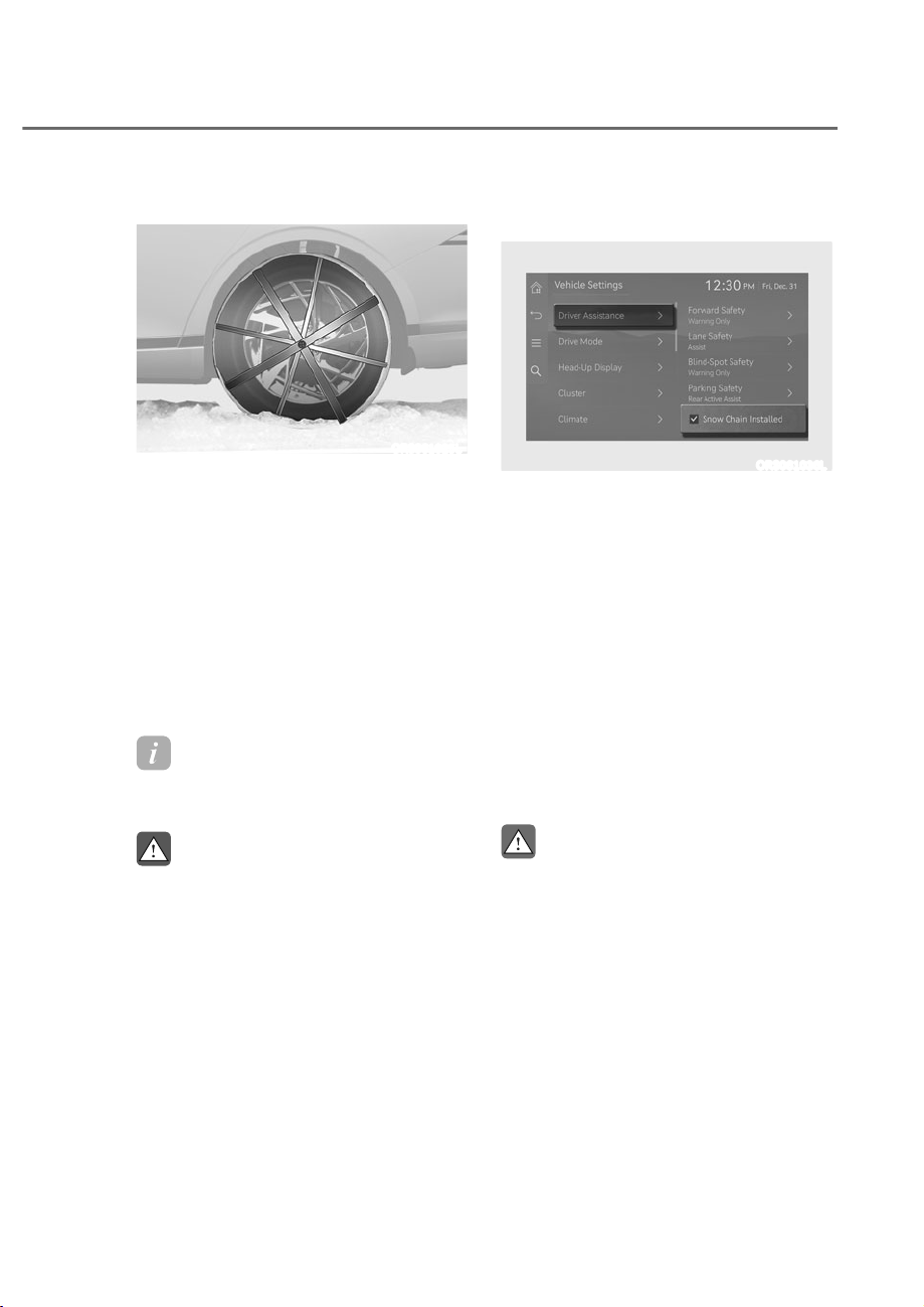
6-71
06
Tire chains
ORS061025L
Since the sidewalls on some radial tires
are thinner than other types of tires,
they may be damaged by mounting
certain types of tire chains on them.
Do not mount tire chains on vehicles
equipped with aluminum wheels; if
possible use AutoSock® (fabric snow
chain or similar). Install AutoSock® after
reviewing the instructions provided
with AutoSock®. Damage to your vehicle
caused by improper use of fabric snow
chains are not covered by your vehicle
manufacturer's warranty.
Information
AutoSock
®
is a Registered trademark of
AutoSock.
WARNING
The use of AutoSock® (fabric snow
chain) may adversely affect vehicle
handling:
ȉ Drive less than 20 mph (30 km/h)
or the AutoSock® manufacturer’s
recommended speed limit,
whichever is lower.
ȉ Drive carefully and avoid bumps,
holes, sharp turns, and other road
hazards, which may cause the
vehicle to bounce.
ȉ Avoid sharp turns or locked wheel
braking.
Disabling Rear Wheel Steering system to
install snow chains
ORS061036L
If the Rear Wheel Steering system is
applied, disable the system to protect the
vehicle when snow chains are installed.
6HOHFWȁ6HWXSɌ9HKLFOHɌ'ULYHU
$VVLVWDQFHɌ6QRZ&KDLQV,QVWDOOHGȂLQ
the infotainment system to disable the
Rear Wheel Steering system.
After selecting ‘Snow Chains Installed’
in the infotainment system, turn the
steering wheel 180 degrees to the left
and right 2 to 3 times while the vehicle is
stopped, and check if the rear wheels are
straight before driving.
After removing the snow chain,
deselect ‘Snow Chains Installed’ in the
infotainment system before driving.
CAUTION
ȉ For your safety, change the Settings
after parking the vehicle at a safe
location.
ȉ After removing the snow chain,
be sure to deselect ‘Snow Chains
Installed’ in the infotainment system
to operate the Rear Wheel Steering
system again.

6-72
Driving Your Vehicle
NOTICE
If you drive without disabling the
Rear Wheel Steering system in the
infotainment system after installing
snow chains, the snow chains can
damage your vehicle’s body or chassis
parts. When you hear the snow chain
hitting the vehicle, stop the vehicle and
check whether the snow chains are
installed properly and whether the Rear
Wheel Steering system is disabled.
Information
ȉ Install AutoSock
®
(fabric snow chain)
only in pairs and on the rear tires.
It should be noted that installing
AutoSock (fabric snow chain) on the
tires will provide a greater driving
force, but will not prevent side skids.
ȉ Do not install studded tires without
first checking local, state and municipal
regulations for possible restrictions
against their use.
hain Installation
When installing AutoSock® (fabric
snow chain), follow the manufacturer's
instructions and mount them as tightly
as possible. Drive slowly (less than 20
mph (30 km/h)) with AutoSock® installed.
If you hear the fabric snow chains
contacting the body or chassis, stop and
tighten them. If they still make contact,
slow down until the noise stops. Remove
the AutoSock® as soon as you begin
driving on cleared roads.
When mounting AutoSock®, park the
vehicle on level ground away from traffic.
Turn on the vehicle Hazard Warning
Flasher and place a triangular emergency
warning device behind the vehicle (if
available).
Always place the vehicle in P (Park),
apply the parking brake and turn off the
engine before installing tire chains.
NOTICE
When using AutoSock® (fabric snow
chain):
ȉ Wrong size fabric snow chains or
improperly installed fabric snow
chains can damage your vehicle's
brake lines, suspension, body and
wheels.
ȉ If you hear noise caused by fabric
snow chains contacting the body,
retighten the fabric snow chains to
prevent contact with the vehicle
body.
ȉ To prevent body damage, retighten
the fabric snow chains after driving
0.3~0.6 miles (0.5~1.0 km).

6-73
06
Winter Precautions
Use high quality ethylene glycol coolant
Your vehicle is delivered with high
quality ethylene glycol coolant in the
cooling system. It is the only type of
coolant that should be used because it
helps prevent corrosion in the cooling
system, lubricates the water pump and
prevents freezing. Be sure to replace or
replenish your coolant in accordance
with the maintenance schedule in
chapter 9. Before winter, have your
coolant tested to assure that its freezing
point is sufficient for the temperatures
anticipated during the winter.
Check battery and cables
Winter temperatures affect battery
performance. Inspect the battery and
cables, as specified in chapter 9. The
battery charging level can be checked by
an authorized retailer of Genesis Branded
products or in a service station.
Change to “winter weight” oil if
necessary
In some regions during winter, it is
recommended to use the “winter
weight” oil with lower viscosity. In
addition, replace the engine oil and filter
if it is close to the next maintenance
interval. Fresh engine oil ensures
optimum engine operation during the
winter months. For further information,
refer to chapter 2. When you are not sure
about a type of winter weight oil, consult
an authorized retailer of Genesis Branded
products.
Check spark plugs and ignition system
Inspect the spark plugs, as specified in
chapter 9. If necessary, replace them.
Also check all ignition wirings and
components for any cracks, wear-out,
and damage.
To prevent locks from freezing
To prevent the locks from being frozen,
spray approved de-icing fluid or glycerin
into key holes. When a lock opening is
already covered with ice, spray approved
de-icing fluid over the ice to remove it.
When an internal part of a lock freezes,
try to thaw it with a heated key. Carefully
use the heated key to avoid an injury.
Use approved window washer anti-
freeze solution in system
To prevent the window washer from
being frozen, add authorized window
washer anti-freeze solution, as specified
on the window washer container.
Window washer anti-freeze solution is
available from an authorized retailer of
Genesis Branded products, and most
vehicle accessory outlets. Do not use
engine coolant or other types of anti-
freeze solution, to prevent any damage
to the vehicle paint.
Do not let your parking brake freeze
Under some conditions your parking
brake can freeze in the engaged position.
This is most likely to happen when there
is an accumulation of snow or ice around
or near the rear brakes or if the brakes
are wet. When there is the risk that your
parking brake may freeze, temporarily
apply it with the gear in P (Park). Also,
block the rear wheels in advance, so the
vehicle may not roll. Then, release the
parking brake.

6-74
Driving Your Vehicle
Do not let ice and snow accumulate
underneath
Under some conditions, snow and ice
can build up under the fenders and
interfere with the steering. When driving
in such conditions during the severe
winter, you should check underneath
the vehicle on a regular basis, to ensure
that the front wheels and the steering
components is unblocked.
Carry emergency equipment
In accordance with weather conditions,
you should carry appropriate emergency
equipment, while driving. Some of the
items you may want to carry include tire
chains, tow straps or chains, flashlight,
emergency flares, sand, shovel, jumper
cables, window scraper, gloves, ground
cloth, coveralls, blanket, etc.
Do not place objects or materials in the
engine compartment
Putting objects or materials in the engine
compartment may cause an engine
failure or combustion, because they may
block the engine cooling. Such damage
will not be covered by the manufacturer’s
warranty.
Drive your vehicle when water vapor
condenses and accumulates inside the
exhaust pipes
When the vehicle is stopped for a
long time in winter while the engine is
running, water vapor may condense and
accumulate inside the exhaust pipes.
Water in the exhaust pipes may cause
noise, etc., but it is drained driving at
medium to high speed.
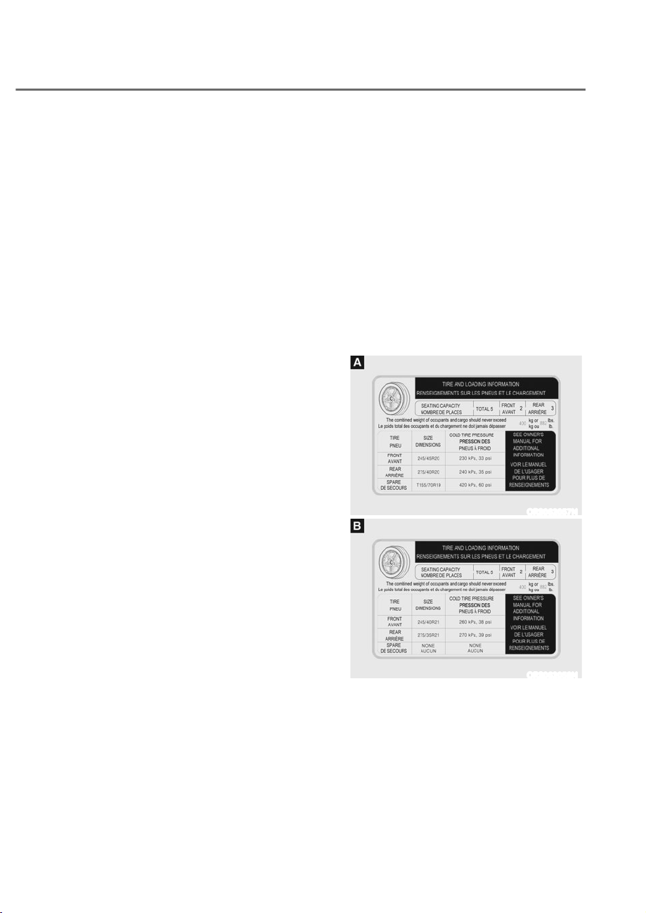
6-75
06
Two labels on your driver’s door sill
show how much weight your vehicle
was designed to carry: the Tire and
Loading Information Label and the
Certification Label.
Before loading your vehicle,
familiarize yourself with the
following terms for determining
your vehicle’s weight ratings, from
the vehicle’s specifications and the
Certification Label:
Base curb weight
This is the weight of the vehicle
including a full tank of fuel and
all standard equipment. It does
not include passengers, cargo, or
optional equipment.
Vehicle curb weight
This is the weight of your new
vehicle when you picked it up from
your dealer plus any aftermarket
equipment.
Cargo weight
This figure includes all weight added
to the Base Curb Weight, including
cargo and optional equipment.
GAW (Gross Axle Weight)
This is the total weight placed on
each axle (front and rear) - including
vehicle curb weight and all payload.
GAWR (Gross Axle Weight Rating)
This is the maximum allowable
weight that can be carried by a single
axle (front or rear). These numbers
are shown on the Certification Label.
The total load on each axle must
never exceed its GAWR.
GVW (Gross Vehicle Weight)
This is the Base Curb Weight
plus actual Cargo Weight plus
passengers.
GVWR (Gross Vehicle Weight Rating)
This is the maximum allowable
weight of the fully loaded vehicle
(including all options, equipment,
passengers and cargo). The GVWR
is shown on the Certification Label
located on the driver’s door sill.
The Loading Information Label
ORS062057N
ORS062058N
The label located on the driver’s door
sill gives the original tire size, cold
tire pressures recommended for your
vehicle, the number of people that
can be in your vehicle and vehicle
capacity weight.
VEHICLE LOAD LIMIT

6-76
Driving Your Vehicle
Vehicle capacity weight
882 lbs. (400 kg)
Vehicle capacity weight is the
maximum combined weight of
occupants and cargo. If your
vehicle is equipped with a trailer,
the combined weight includes the
tongue load.
Seating capacity
Total : 5 persons (Front seat : 2
persons, Rear seat : 3 persons)
Seating capacity is the maximum
number of occupants including
a driver, your vehicle may carry.
However, the seating capacity may
be reduced based upon the weight
of all of the occupants, and the
weight of the cargo being carried or
towed. Do not overload the vehicle
as there is a limit to the total weight,
or load limit including occupants and
cargo, the vehicle can carry.
Towing capacity
We do not recommend using this
vehicle for trailer towing.
Cargo capacity
The cargo capacity of your vehicle
will increase or decrease depending
on the weight and the number of
occupants and the tongue load,
if your vehicle is equipped with a
trailer.
Steps for determining correct load
limit
1. Locate the statement "The
combined weight of occupants
and cargo should never exceed
XXX kg or XXX lbs." on your
vehicle's placard.
2. Determine the combined weight
of the driver and passengers that
will be riding in your vehicle.
3. Subtract the combined weight of
the driver and passengers from
XXX kg or XXX lbs.
4. The resulting figure equals
the available amount of cargo
and luggage load capacity. For
example, if the "XXX" amount
equals 1400 lbs. and there will
be five 150 lb passengers in your
vehicle, the amount of available
cargo and luggage load capacity
is 650 lbs. (1400 - 750 (5 x 150) =
650 lbs.)
5. Determine the combined weight
of luggage and cargo being
loaded on the vehicle. That
weight may not safely exceed the
available cargo and luggage load
capacity calculated in Step 4.
6. If your vehicle will be towing a
trailer, load from your trailer will
be transferred to your vehicle.
Consult this manual to determine
how this reduces the available
cargo and luggage load capacity
of your vehicle.

6-77
06
WARNING
Do not overload the vehicle as there is a limit to the total weight, or load
limit, including occupants and cargo, the vehicle can carry. Overloading
can shorten the life of the vehicle. If the GVWR or the GAWR is exceeded,
parts on the vehicle can be broken, and it can change the handling of your
vehicle. These could cause you to lose control and result in an accident.
Example 1
ȕ +
Maximum
Load
(1400 lbs.)
(635 kg)
Passenger Weight
(150 lbs. × 2 = 300 lbs.)
(68 kg × 2 = 136 kg)
Cargo Weight
(1100 lbs.)
(499 kg)
Example 2
ȕ +
Maximum
Load
(1400 lbs.)
(635 kg)
Passenger Weight
(150 lbs. × 5 = 750 lbs.)
(68 kg × 5 = 340 kg)
Cargo Weight
(650 lbs.)
(295 kg)
Example 3
ȕ +
Maximum
Load
(1400 lbs.)
(635 kg)
Passenger Weight
(172 lbs. × 5 = 860 lbs.)
(78 kg × 5 = 390 kg)
Cargo Weight
(540 lbs.)
(245 kg)
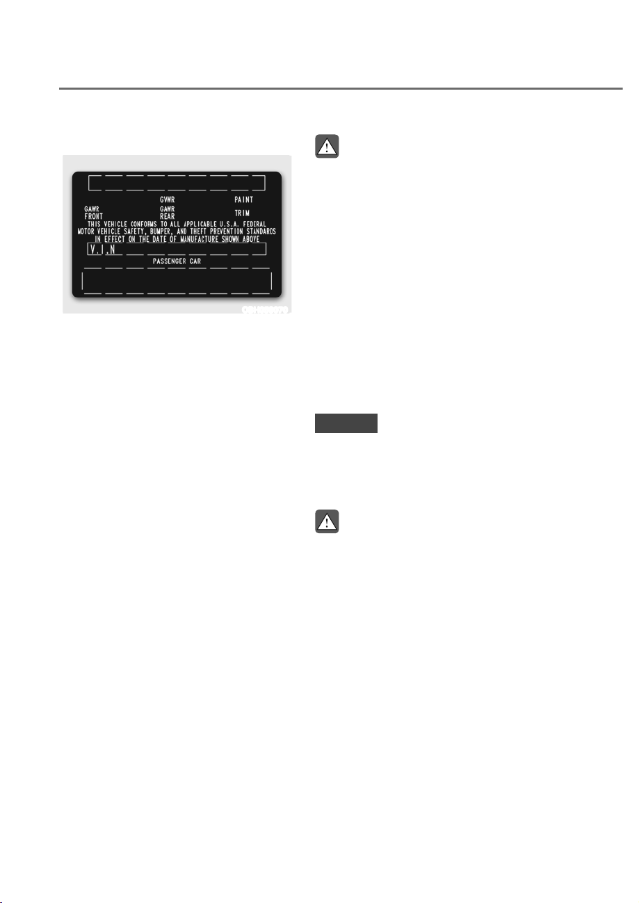
6-78
Driving Your Vehicle
Certification label
OBH059070
The certification label is located on
the driver's door sill at the center
pillar and shows the maximum
allowable weight of the fully loaded
vehicle. This is called the GVWR
(Gross Vehicle Weight Rating). The
GVWR includes the weight of the
vehicle, all occupants, fuel and
cargo.
This label also tells you the maximum
weight that can be supported by the
front and rear axles, called Gross
Axle Weight Rating (GAWR).
The total weight of the vehicle,
including all occupants, accessories,
cargo, and trailer tongue load must
not exceed the Gross Vehicle Weight
Rating (GVWR) or the Gross Axle
Weight Rating (GAWR). To find out
the actual loads on your front and
rear axles, you need to go to a weigh
station and weigh your vehicle. Be
sure to spread out your load equally
on both sides of the centerline.
WARNING
Overloading
ȉ Never exceed the GVWR for your
vehicle, the GAWR for either the
front or rear axle and vehicle
capacity weight. Exceeding these
ratings can affect your vehicle's
handling and braking ability, and
cause an accident.
ȉ Do not overload your vehicle.
Overloading your vehicle can
cause heat buildup in your
vehicle's tires and possible
tire failure, increased stopping
distances and poor vehicle
handling-all of which may result
in a crash.
NOTICE
Overloading your vehicle may cause
damage. Repairs would not be
covered by your warranty. Do not
overload your vehicle.
WARNING
If you carry items inside your vehicle
(for example, suitcases, tools,
packages, or anything else), they
are moving as fast as the vehicle. If
you have to stop or turn quickly, or if
there is a crash, the items will keep
going and can cause an injury if they
strike the driver or a passenger.
ȉ Put items in the cargo area of
your vehicle. Try to spread the
weight evenly.
ȉ Do not stack items like suitcases
inside the vehicle above the tops
of the seats.
ȉ Do not leave an unsecured child
restraint in your vehicle.
ȉ When you carry something inside
the vehicle, secure it.

6-79
06
TRAILER TOWING
We do not recommend using this vehicle for trailer towing.

7
Driving Safety
Forward Collision–Avoidance Assist (FCA) .............................................................7-2
Lane Keeping Assist (LKA)
..................................................................................... 7-30
Blind-Spot Collision-Avoidance Assist (BCA)
....................................................... 7-37
Safe Exit Assist (SEA)
............................................................................................. 7-49
Manual Speed Limit Assist (MSLA)
........................................................................ 7-56
Intelligent Speed Limit Assist (ISLA)
...................................................................... 7-59
Driver Attention Warning (DAW)
........................................................................... 7-66
Blind-Spot View Monitor (BVM)
............................................................................. 7-72
Driving Convenience
Smart Cruise Control (SCC) ................................................................................... 7-74
Navigation-based Smart Cruise Control (NSCC)
.................................................. 7-93
Lane Following Assist (LFA)
................................................................................... 7-99
Highway Driving Assist (HDA)
.............................................................................. 7-103
Parking Safety
Surround View Monitor (SVM) ............................................................................ 7-115
Rear Cross-Traffic Collision-Avoidance Assist (RCCA)
...................................... 7-120
Forward/SIde/Reverse Parking Distance Warning (PDW)
.................................. 7-131
Forward/Side/Reverse Parking Collision-Avoidance Assist (PCA)
.................... 7-139
Parking Convenience
Remote Smart Parking Assist 2 (RSPA 2) ........................................................... 7-147
Declaration of conformity
.......................................................................................... 7-175
7. Driver Assistance System
Due to the infotainment or Driver Assistance system software version, the description of each
function may differ from the owner's manual.
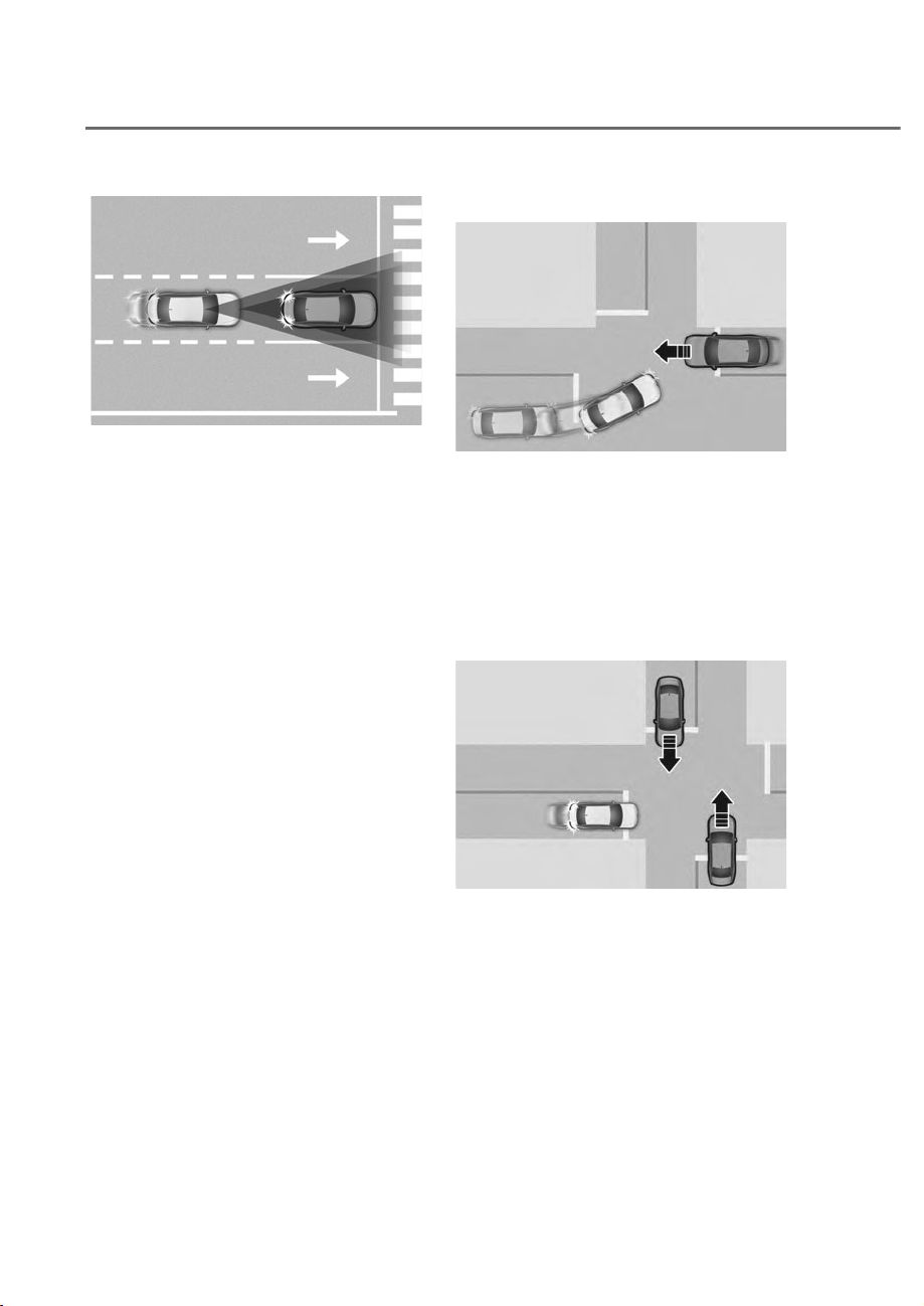
7-2
Driver Assistance System
ORS071083
ORS071083
Forward Collision-Avoidance Assist helps
detect a vehicle, a powered two-wheeler,
a pedestrian, or a cyclist ahead on the
road and may warn you of a possible
collision with a warning message on the
instrument cluster and a warning sound.
Also, Forward Collision-Avoidance Assist
may assist with braking your vehicle to
help reduce collision speed or help avoid
a collision.
In addition, when driving at high speeds,
Forward Collision-Avoidance Assist
will help detect vehicles in front and
adjacent lanes. If a collision is imminent
when changing lanes, Forward Collision-
Avoidance Assist will apply emergency
braking to help reduce collision speed or
help avoid a collision.
Junction Turning function
ORS071055
ORS071055
Junction Turning function can help avoid
a collision with an oncoming vehicle
in an adjacent lane when turning left
at a crossroad with the turn signal on
by applying emergency braking. Also,
Junction Turning function may assist
with braking your vehicle to help reduce
collision speed or avoid a collision.
Junction Crossing function
ORS071056
ORS071056
Junction Crossing function can help
avoid a collision with oncoming vehicles
on the left or right side when crossing
an intersection by applying emergency
braking. Also, Junction Crossing function
may assist with braking your vehicle to
help reduce collision speed or avoid a
collision.
)25:$5'&2//,6,21ʐ$92,'$1&($66,67ʚ)&$ʛ
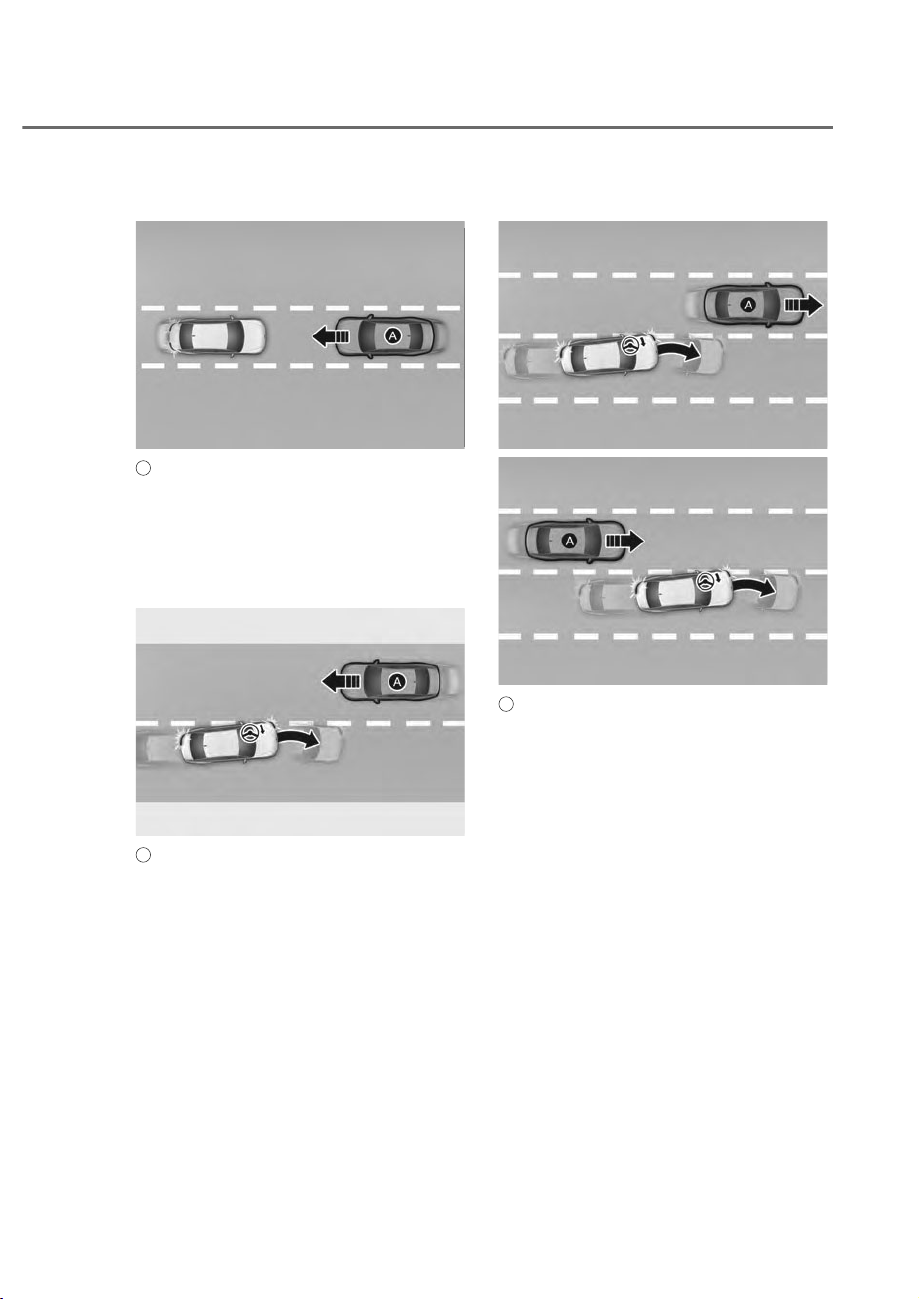
7-3
07
Direct Oncoming function
ORS071176
ORS071176
A
: Oncoming vehicle
Direct Oncoming function helps reduce
the speed at the collision when a vehicle
approaching from the opposite side is
detected.
Lane-Change Oncoming function
ORS071057
ORS071057
A
: Oncoming vehicle
Lane-Change Oncoming function helps
avoid a collision with an oncoming
vehicle when changing lanes by assisting
the driver’s steering. Also, Lane-Change
Oncoming function may assist with
braking your vehicle to help reduce
collision speed or avoid a collision.
Lane-Change Side function
ORS071058
ORS071058
ORS072058N
ORS072058N
A
: Front-side vehicle
Lane-Change Side function helps avoid
a collision with the vehicle ahead in
the next lane when changing lanes by
assisting the driver’s steering. Also,
Lane-Change Side function may assist
with braking your vehicle to help reduce
collision speed or avoid a collision.
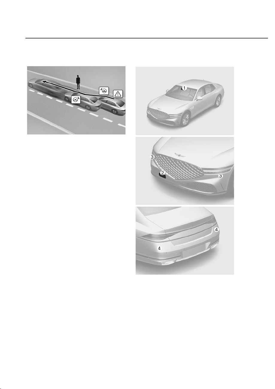
7-4
Driver Assistance System
(YDVLYH6WHHULQJ$VVLVWIXQFWLRQ
ORS073053CN
ORS073053CN
• Driver steering assist
Evasive Steering Assist function
helps avoid a collision with a vehicle,
pedestrian or cyclist ahead in the
same lane. When a risk of collision
is detected, Evasive Steering Assist
function will warn the driver and if the
driver steers to avoid the collision it
will assist the driver’s steering.
• Evasive steering assist
Evasive Steering Assist function helps
avoid a collision with a pedestrian or
cyclist ahead in the same lane. When
a risk of collision is detected, Evasive
Steering Assist function will warn the
driver and if there is space to avoid
collision in the lane, it will assist the
driver’s steering.
Detecting sensor
ORS071001
ORS071001
ORS072292
ORS072292
ORS072003N
ORS072003N
M: Front view camera,
N: Front radar,
O: Front corner radar,
P: Rear corner radar
Refer to the picture above for the
detailed location of the detecting
sensors.

7-5
07
CAUTION
Take the following precautions to
maintain optimal performance of the
detecting sensor:
• 1HYHUGLVDVVHPEOHWKHGHWHFWLQJ
VHQVRURUVHQVRUDVVHPEO\RUFDXVH
DQ\GDPDJHWRLW
• ,IWKHGHWHFWLQJVHQVRUVKDYHEHHQ
UHSODFHGRUUHSDLUHGKDYH\RXU
YHKLFOHLQVSHFWHGE\DQDXWKRUL]HG
UHWDLOHURI*HQHVLV%UDQGHGSURGXFWV
• 1HYHULQVWDOODQ\DFFHVVRULHVRU
VWLFNHUVRQWKHIURQWZLQGVKLHOGRU
WLQWWKHIURQWZLQGVKLHOG
• ([HUFLVHH[WUHPHFDXWLRQWRNHHSWKH
IURQWYLHZFDPHUDGU\
• 1HYHUSODFHDQ\UHIOHFWLYHREMHFWV
IRUH[DPSOHZKLWHSDSHUPLUURU
RYHUWKHGDVKERDUG
• 'RQRWSODFHDQ\REMHFWVQHDUWKH
IURQWZLQGVKLHOGRULQVWDOODQ\
DFFHVVRULHVRQWKHIURQWZLQGVKLHOG
It can affect the performance of the
defogging and defrosting function
RIWKHFOLPDWHFRQWUROV\VWHPZKLFK
PD\SUHYHQWWKH'ULYHU$VVLVWDQFH
V\VWHPVIURPRSHUDWLQJ
• 'RQRWDSSO\OLFHQVHSODWHIUDPHRU
REMHFWVVXFKDVDEXPSHUVWLFNHU
ILOPRUDEXPSHUJXDUGQHDUWKH
IURQWUDGDUFRYHU
• $OZD\VNHHSWKHIURQWUDGDUDQG
FRYHUFOHDQDQGIUHHRIGLUWDQG
GHEULV
8VHRQO\DVRIWFORWKWRZDVKWKH
YHKLFOH'RQRWVSUD\SUHVVXUL]HG
ZDWHUGLUHFWO\RQWKHVHQVRURU
VHQVRUFRYHU
• If the radar or the area around
WKHUDGDUKDVEHHQGDPDJHGRU
LPSDFWHGLQDQ\ZD\)RUZDUG
&ROOLVLRQ$YRLGDQFH$VVLVWPD\QRW
SURSHUO\RSHUDWHHYHQWKRXJKD
warning message does not appear
RQWKHFOXVWHU+DYHWKHYHKLFOH
LQVSHFWHGE\DQDXWKRUL]HGUHWDLOHURI
*HQHVLV%UDQGHGSURGXFWV
• 8VHRQO\JHQXLQHSDUWVWRUHSDLURU
UHSODFHDGDPDJHGIURQWUDGDUFRYHU
'RQRWDSSO\SDLQWWRWKHIURQWUDGDU
FRYHU
• 9HKLFOHVHTXLSSHGZLWKIURQWFRUQHU
radar and/or rear corner radar
- 'RQRWDSSO\OLFHQVHSODWHIUDPHRU
REMHFWVVXFKDVDEXPSHUVWLFNHU
ILOPRUDEXPSHUJXDUGQHDUWKH
front corner radar or rear corner
UDGDU
- 7KHIXQFWLRQPD\QRWZRUN
SURSHUO\ZKHQWKHEXPSHUKDV
EHHQUHSODFHGRUWKHVXUURXQGLQJV
of the front corner radar or rear
FRUQHUUDGDUKDVEHHQGDPDJHGRU
SDLQWKDVEHHQDSSOLHG
- ,IDWUDLOHUFDUULHUHWFLVLQVWDOOHG
LWPD\DGYHUVHO\DIIHFWWKH
performance of the rear corner
radar or Forward Collision-
$YRLGDQFH$VVLVWPD\QRWRSHUDWH
SURSHUO\
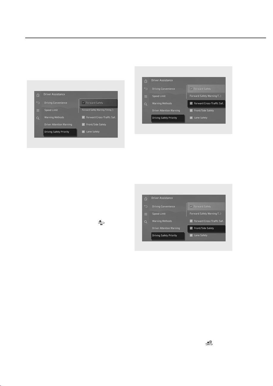
7-6
Driver Assistance System
)RUZDUG&ROOLVLRQ$YRLGDQFH
Assist Settings
Forward Safety
ORS073230N
ORS073230N
With the engine on, select or deselect
ȁ'ULYHU$VVLVWDQFHɌ'ULYLQJ6DIHW\ȂIURP
the Settings menu to set whether to use
each function.
• If Forward Safety is selected, Forward
Collision-Avoidance Assist will warn
the driver with a warning message,
an audible warning depending on
the collision risk levels. Braking assist
will be applied depending on the
collision risk levels. If Forward Safety
is deselected, Forward Safety will
turn off. The warning light (
) will
illuminate on the instrument cluster.
Forward Cross-Traffic Safety
ORS073231N
ORS073231N
With the engine on, select ‘Driver
$VVLVWDQFHɌ'ULYLQJ6DIHW\Ɍ)RUZDUG
Cross-Traffic Safety’ from the Settings
menu to turn on Junction Crossing
function and deselect to turn off the
function.
Forward/Side Safety
ORS073333N
ORS073333N
With the engine on, select or deselect
ȁ'ULYHU$VVLVWDQFHɌ'ULYLQJ6DIHW\Ɍ
Forward/Side Safety’ from the Settings
menu to turn on Lane-Change Oncoming
function, Lane-Change Side function,
and Evasive Steering Assist function.
• If Forward/Side Safety is selected,
Forward Collision-Avoidance Assist
will warn the driver, steering wheel
vibration, a warning message, an
audible warning depending on the
collision risk levels. Steering assist will
be applied depending on the collision
risk levels. If Forward/Side Safety is
deselected, Forward/Side Safety will
turn off. The warning light (
) will
illuminate on the instrument cluster.
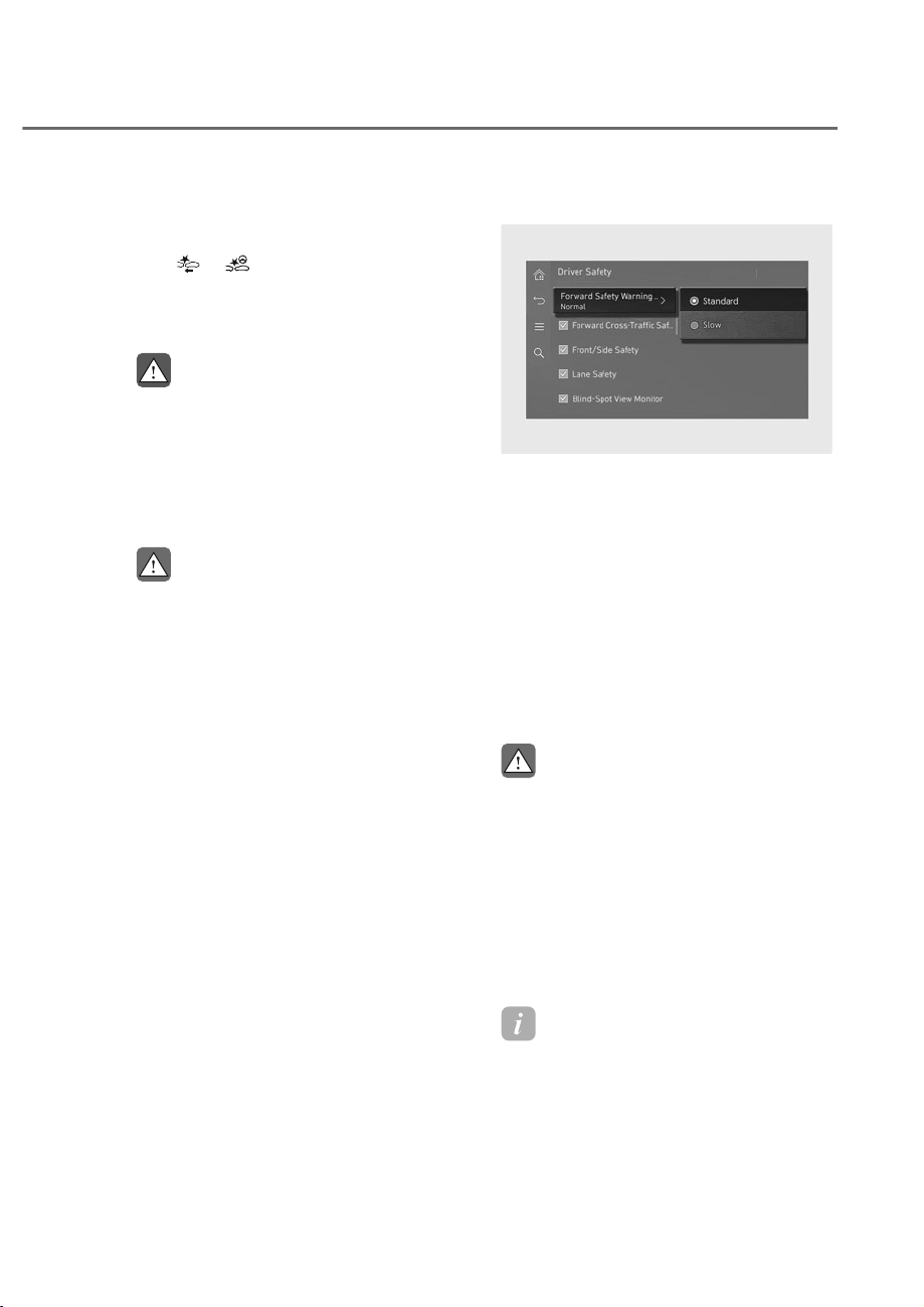
7-7
07
The driver can monitor Forward
Collision-Avoidance Assist On/Off status
from the Settings menu. If the warning
light
or remains ON when Forward
Collision-Avoidance Assist is on, have
the vehicle inspected by an authorized
retailer of Genesis Branded products.
WARNING
:KHQWKHHQJLQHLVUHVWDUWHG)RUZDUG
&ROOLVLRQ$YRLGDQFH$VVLVWZLOODOZD\V
WXUQRQ+RZHYHULIȁ)RUZDUG6DIHW\Ȃ
ȁ)RUZDUG&URVV7UDIILF6DIHW\ȂDQG
ȁ)RUZDUG6LGH6DIHW\ȂLVGHVHOHFWHGWKH
GULYHUVKRXOGDOZD\VEHDZDUHRIWKH
VXUURXQGLQJVDQGGULYHVDIHO\
CAUTION
• 7KHVHWWLQJIRU)RUZDUG6DIHW\
LQFOXGHȁ%DVLFIXQFWLRQȂDQGȁ-XQFWLRQ
7XUQLQJȂ
• The setting for Forward Cross Traffic-
6DIHW\LQFOXGHVȁ-XQFWLRQ&URVVLQJȂ
• 7KHVHWWLQJIRU)RUZDUG6LGH6DIHW\
LQFOXGHVȁ/DQH&KDQJH2QFRPLQJȂ
ȁ/DQH&KDQJH6LGHȂDQGȁ(YDVLYH
6WHHULQJ$VVLVWȂ
• ,Iȁ)RUZDUG6DIHW\ȂLVGHVHOHFWHG
Junction Crossing function will not
RSHUDWHHYHQZKHQȁ)RUZDUG&URVV
7UDIILF6DIHW\ȂDQGȁ)RUZDUG6LGH
6DIHW\ȂLVVHOHFWHG
• 6WHHULQJZKHHOYLEUDWLRQFDQEH
WXUQHGRQRURII
• If a trailer or hitch mounted carrier
LVDWWDFKHGLWPD\DGYHUVHO\DIIHFW
the performance of the Forward
&ROOLVLRQ$YRLGDQFHDVVLVW
Forward Safety Warning timing
ORS073330N
ORS073330N
With the engine on, select ‘Driver
$VVLVWDQFHɌ'ULYLQJ6DIHW\Ɍ)RUZDUG
Safety Warning Timing’ from the Settings
menu to change the initial warning
activation time for Forward Collision-
Avoidance Assist. The warning time can
be set to either ‘Standard’ or ‘Late’.
• Use ‘Standard’ in normal driving
conditions. If the Warning Timing
seems sensitive, change it to ‘Late’.
• If ‘Late’ is selected, Forward Collision-
Avoidance Assist, warns the driver
more slowly.
CAUTION
• The setting of the Warning Timing
applies to all functions of Forward
&ROOLVLRQ$YRLGDQFH$VVLVW
• (YHQWKRXJK6WDQGDUGLVVHOHFWHG
IRU:DUQLQJ7LPLQJLIDGHWHFWHG
YHKLFOHLQIURQWVXGGHQO\VWRSVWKH
ZDUQLQJPD\VHHPODWH
• Select 'Late' for Warning Timing
ZKHQWUDIILFLVOLJKWDQGZKHQGULYLQJ
VSHHGLVVORZ
Information
• Warning timing settings do not apply to
Forward/Side Safety.
• If the vehicle is restarted, Warning
timing will maintain the last setting.
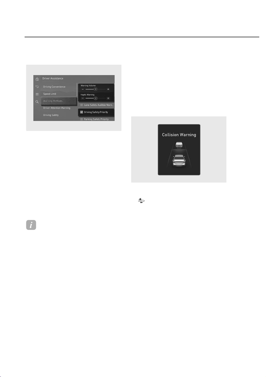
7-8
Driver Assistance System
Warning methods
ORS073334N
ORS073334N
With the engine on, go to 'Driver
$VVLVWDQFHɌ:DUQLQJ0HWKRGVIURPWKH
Settings in the infotainment system to
select the following:
• Warning Volume: The warning volume
can be adjusted. If you turn off the
Warning Volume, for your safety, the
function may warn you with a low
volume.
• Haptic Warning: The steering wheel
vibration can be set.
• Driving Safety Priority: Your vehicle
lowers all other audio volumes when the
Driver Assistance system warning sounds.
Information
• If you change the Warning Methods,
Warning Methods of other Driver
Assistance systems may change.
• Warning Method will maintain its last
setting even if the vehicle is restarted.
• The setting menu may not be available
for your vehicle depending on the
vehicle features and specifications.
• The Warning olume and Haptic
Warning cannot be turned off at the
same time. When one of the warning is
turned off the other is activated.
)RUZDUG&ROOLVLRQ$YRLGDQFH
Assist operation
Basic function
The basic function for Forward Collision-
Avoidance Assist is to warn and help
control the vehicle depending on the
collision risk level: ‘Collision Warning’,
‘Emergency Braking’ and ‘Stop vehicle
and end brake control’.
ORS071096L
ORS071096L
ollision Warning
• To warn the driver of a collision, the
waring light will blink and the
'Collision Warning' warning message
will appear on the instrument cluster.
Also, an audible warning will sound
and the steering wheel will vibrate.
• If a vehicle or powered two-wheeler
is detected in front, the function will
operate when your vehicle speed is
between approximately 6-124 mph
(10-200 km/h).
• If a pedestrian or cyclist is detected
in front, the function will operate
when your vehicle speed is between
approximately 6-53 mph (10-85 km/h).
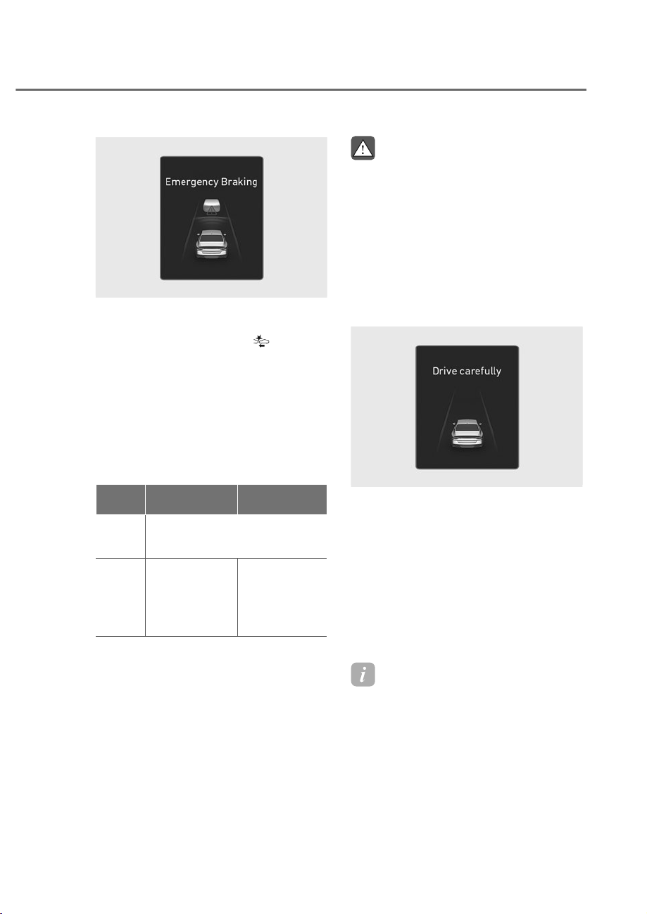
7-9
07
ORS071097L
ORS071097L
Emergency Braking
To warn the driver that emergency
braking will be assisted, the
waring
light will blink and the 'Emergency
Braking' warning message will appear on
the instrument cluster. Also, an audible
warning will sound and the steering
wheel will vibrate.
Emergency braking will operate under
the following conditions.
• Vehicle or powered two-wheeler:
'ULYLQJYHKLFOH
Stopped
YHKLFOH
Weak
braking
power
Approximately 6-125 mph
(10-200 km/h)
Strong
braking
power
Approximately
6-81 mph
(10-130 km/h)
Approximately
6-47 mph
(10-75 km/h)
(6-62 mph
(10-100 km/h))*
*: If Forward Collision-Avoidance Assist judges that
avoiding a collision is difficult even by changing
the driving lane. The function operation range may
decrease due to surroundings of the vehicle.
• Pedestrian or cyclist:
The function will operate when
your vehicle speed is between
approximately 6-40 mph (10-65
km/h).
WARNING
• )RUZDUG&ROOLVLRQ$YRLGDQFH
$VVLVWPD\WXUQRIIRUPD\QRW
RSHUDWHSURSHUO\RUPD\RSHUDWH
XQQHFHVVDULO\GHSHQGLQJRQWKHDQG
WKHVXUURXQGLQJV
• :KHQGULYLQJDWQLJKWWKH
powered two wheeler recognition
SHUIRUPDQFHLVGHJUDGHGVR
)RUZDUG&ROOLVLRQ$YRLGDQFH$VVLVW
PD\EHWHPSRUDULO\OLPLWHGRUPD\
QRWZRUN
ORS071102L
ORS071102L
Stop vehicle and end brake control
• When the vehicle is stopped due
to emergency braking, the ‘Drive
carefully’ warning message will
appear on the instrument cluster.
For your safety, the driver should
depress the brake pedal immediately
and check the surroundings.
• Brake control will end after the vehicle
is stopped by emergency braking for
approximately 2 seconds.
Information
The audible warning can be turned off
while collision warning or emergency
braking is operating by pressing the
hazard warning flasher button.
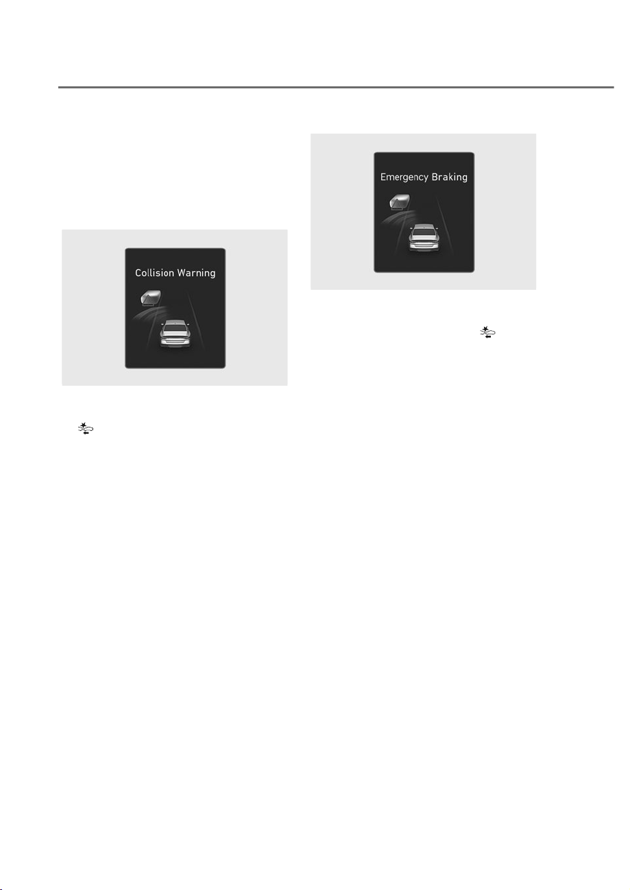
7-10
Driver Assistance System
Junction Turning function
Junction Turning function will warn and
control the vehicle depending on the
collision risk level: ‘Collision Warning’,
‘Emergency Braking’ and ‘Stop vehicle
and end brake control’.
ORS071098L
ORS071098L
ollision Warning
• To warn the driver of a collision, the
waring light will blink and the
'Collision Warning' warning message
will appear on the instrument cluster.
Also, an audible warning will sound
and the steering wheel will vibrate.
• The function will operate when
your vehicle speed is between
approximately 6-19 mph (10-30 km/h)
and the oncoming vehicle or powered
two-wheeler speed is between
approximately 19-44 mph (30-70
km/h).
ORS071099L
ORS071099L
Emergency Braking
• To warn the driver that emergency
braking will be assisted, the
waring
light will blink and the 'Emergency
Braking' warning message will appear
on the instrument cluster. Also, an
audible warning will sound and the
steering wheel will vibrate.
• In an emergency braking situation,
braking is assisted with strong braking
power by the function to help prevent
a collision with the oncoming vehicle.
• The function will operate when
your vehicle speed is between
approximately 6-19 mph (10-30 km/h)
and the oncoming vehicle or powered
two-wheeler speed is between
approximately 19-44 mph (30-70
km/h).
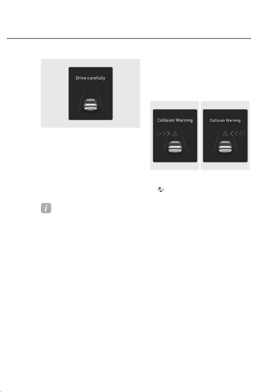
7-11
07
ORS071102L
ORS071102L
Stop vehicle and end brake control
• When the vehicle is stopped due
to emergency braking, the ‘Drive
carefully’ warning message will
appear on the instrument cluster.
For your safety, the driver should
depress the brake pedal immediately
and check the surroundings.
• Brake control will end after the vehicle
is stopped by emergency braking for
approximately 2 seconds.
Information
The audible warning can be turned off
while collision warning or emergency
braking is operating by pressing the
hazard warning flasher button.
Junction Crossing function
Junction Crossing function will warn
and control the vehicle depending on
collision risk level: ‘Collision Warning’,
‘Emergency Braking’ and ‘Stop vehicle
and end brake control’
ORS071100L
ORS071100L
ORS071282L
ORS071282L
ollision Warning
• To warn the driver of a collision, the
waring light will blink and the
'Collision Warning' warning message
will appear on the instrument cluster.
Also, an audible warning will sound
and the steering wheel will vibrate.
• The function will operate when
your vehicle speed is between
approximately 6-34 mph (10-55
km/h) and the crossing vehicle speed
is between approximately 6-37 mph
(10-60 km/h)
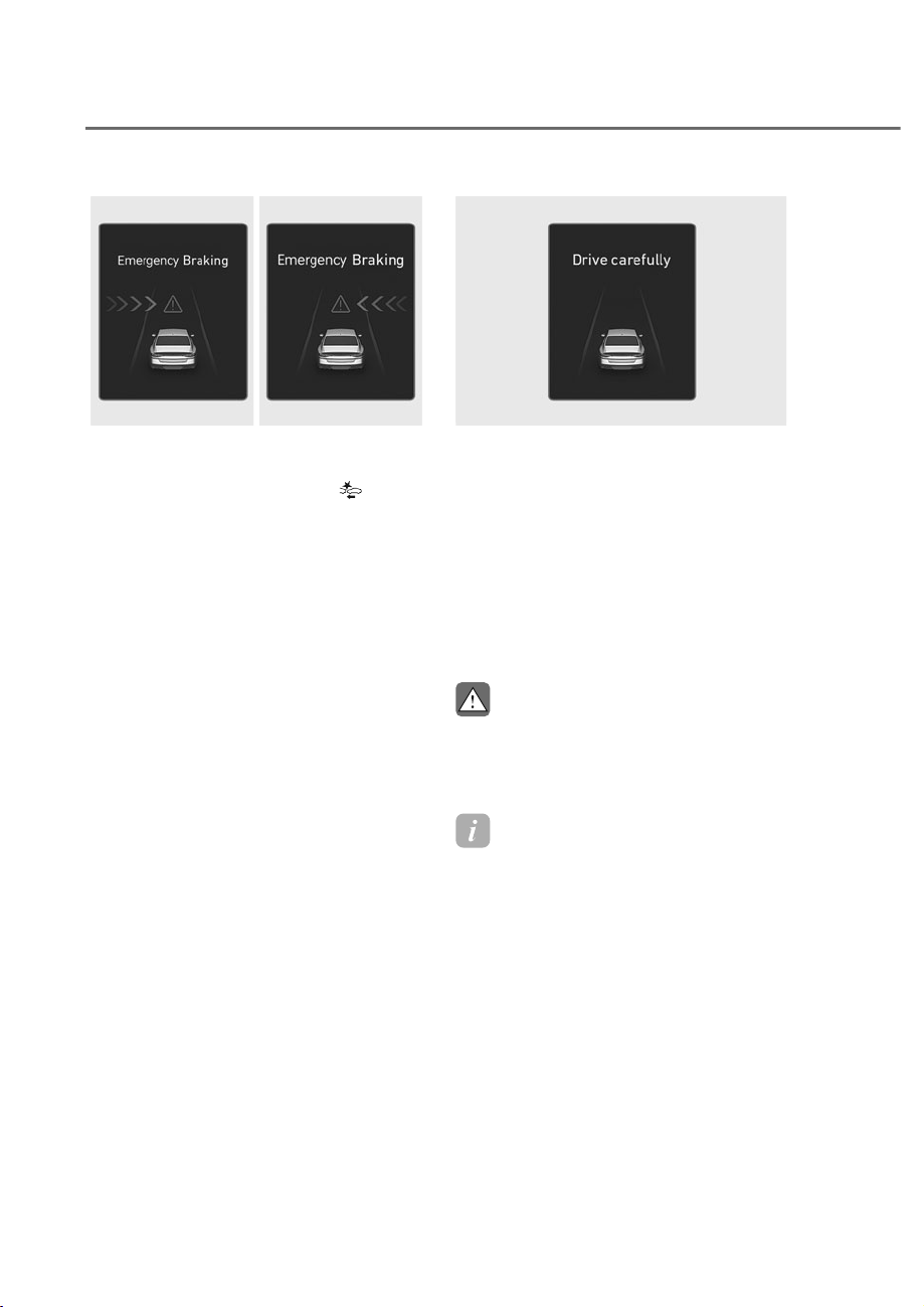
7-12
Driver Assistance System
ORS071103L
ORS071103L
ORS071101L
ORS071101L
Emergency Braking
• To warn the driver that emergency
braking will be assisted, the
waring
light will blink and the 'Emergency
Braking' warning message will appear
on the instrument cluster. Also, an
audible warning will sound and the
steering wheel will vibrate.
• In an emergency braking situation,
braking is assisted with strong braking
power by the function to help prevent
a collision with the crossing vehicle.
• The function will operate when
your vehicle speed is between
approximately 6-34 mph (10-55 km/h)
and the crossing vehicle speed is
between approximately 6-25 mph (10-
40 km/h).
ORS071102L
ORS071102L
Stop vehicle and end brake control
• When the vehicle is stopped due
to emergency braking, the ‘Drive
carefully’ warning message will
appear on the instrument cluster.
For your safety, the driver should
depress the brake pedal immediately
and check the surroundings.
• Brake control will end after the vehicle
is stopped by emergency braking for
approximately 2 seconds.
CAUTION
If the collision angle with the crossing
YHKLFOHLVEH\RQGDFHUWDLQUDQJH
Junction Crossing function warning and
FRQWUROPD\EHODWHRUPD\QRWRSHUDWH
Information
The audible warning can be turned off
while collision warning or emergency
braking is operating by pressing the
hazard warning flasher button.
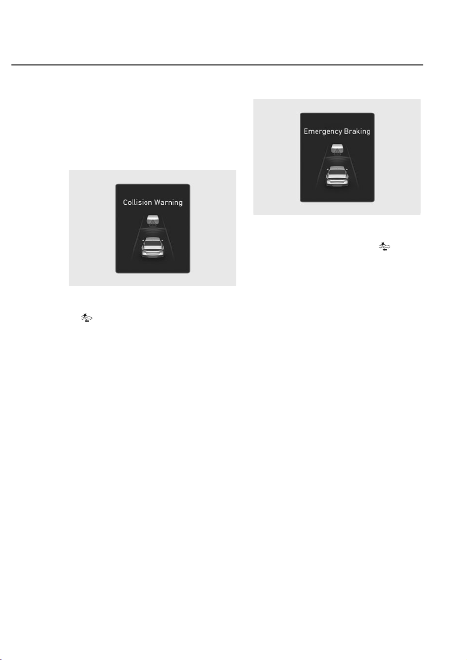
7-13
07
Direct Oncoming function
Direct Oncoming function will warn
and control the vehicle depending
on the collision risk level: ‘Collision
Warning’,‘Emergency Braking’ and ‘Stop
vehicle and end brake control’.
ORS071096L
ORS071096L
ollision Warning
• To warn the driver of a collision, the
waring light will blink and the
'Collision Warning' warning message
will appear on the instrument cluster.
Also, an audible warning will sound
and the steering wheel will vibrate.
• The function will operate when
your vehicle speed is between
approximately 6-80 mph (10-130
km/h) and the detected oncoming
vehicle speed is approximately above
6 mph (10 km/h).
ORS071097L
ORS071097L
Emergency Braking
• To warn the driver that emergency
braking will be assisted, the
waring
light will blink and the 'Emergency
Braking' warning message will appear
on the instrument cluster. Also, an
audible warning will sound and the
steering wheel will vibrate.
• In an emergency braking situation,
braking is assisted with strong braking
power by the function to help prevent
a collision with the oncoming vehicle.
• The function will operate when
your vehicle speed is between
approximately 19-80 mph (30-130
km/h) and the detected oncoming
vehicle speed is approximately above
6 mph (10 km/h).
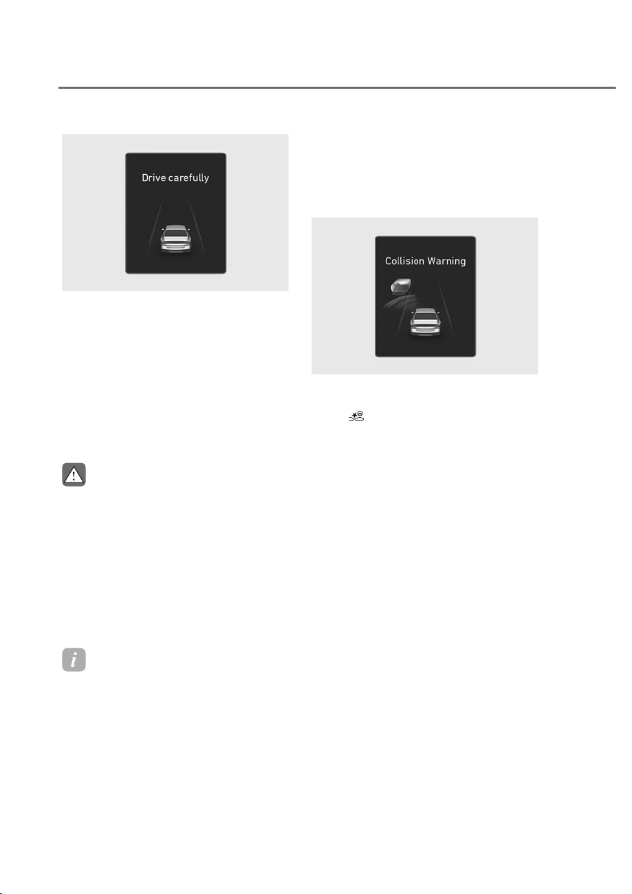
7-14
Driver Assistance System
ORS071102L
ORS071102L
Stop vehicle and end brake control
• When the vehicle is stopped due
to emergency braking, the ‘Drive
carefully’ warning message will
appear on the instrument cluster. For
your safety, the driver should depress
the brake pedal immediately and
check the surroundings.
• Brake control will end after the vehicle
is stopped by emergency braking for
approximately 2 seconds.
CAUTION
• ,I\RXUYHKLFOHRUWKHRQFRPLQJ
YHKLFOHLVQRWGULYLQJVWUDLJKW'LUHFW
Oncoming function warning and
FRQWUROPD\EHODWHRUPD\QRW
RSHUDWH
• :KHQGULYLQJDWQLJKWWKH
powered two wheeler recognition
SHUIRUPDQFHLVGHJUDGHGVR
)RUZDUG&ROOLVLRQ$YRLGDQFH$VVLVW
PD\EHWHPSRUDULO\OLPLWHGRUPD\
QRWZRUN
Information
The audible warning can be turned off
while collision warning or emergency
braking is operating by pressing the
hazard warning flasher button.
Lane-Change Oncoming function
Lane-Change Oncoming function will
warn and control the vehicle depending
on collision risk level: ‘Collision Warning’
and ‘Emergency Steering’
ORS071098L
ORS071098L
ollision Warning
• To warn the driver of a collision,
the
warning light will blink
and the 'Emergency Steering'
warning message will appear on the
instrument cluster. Also, an audible
warning will sound and the steering
wheel will vibrate.
• The function will operate when
your vehicle speed is between
approximately 25-90 mph (40-145
km/h) and the oncoming vehicle
or powered two-wheeler speed is
approximately above 6 mph (10 km/h)
and the relative speed with your
vehicle is approximately below 124
mph (200 km/h).
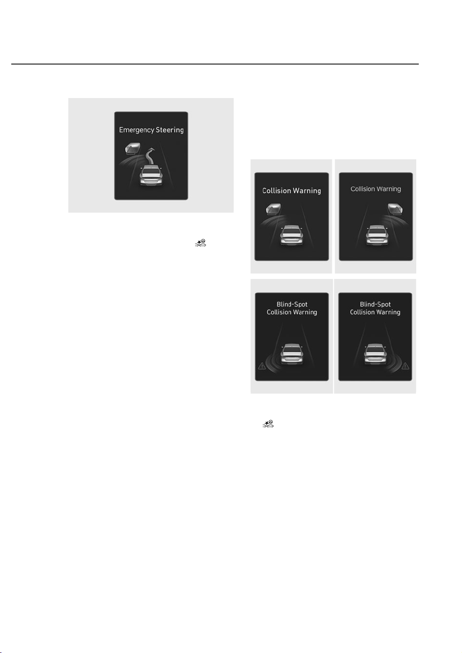
7-15
07
ORS071105L
ORS071105L
Emergency Steering
• To warn the driver that emergency
steering will be assisted, the
warning light will blink and the
'Emergency Steering' warning
message will appear on the
instrument cluster. Also, an audible
warning will sound and the steering
wheel will vibrate.
• In an emergency steering situation,
steering is assisted by the function
to help prevent a a collision with the
oncoming vehicle.
• The function will operate when
your vehicle speed is between
approximately 25-90 mph (40-145
km/h) and the oncoming vehicle
or powered two-wheeler speed is
approximately above 6 mph (10 km/h)
and the relative speed with your
vehicle is approximately below 124
mph (200 km/h).
Lane-Change Side function
Lane-Change Side function will warn
and control the vehicle depending on
collision risk level: ‘Collision Warning’
and ‘Emergency Steering’
ORS071098L
ORS071098L
ORS071198L
ORS071198L
ORS073331N
ORS073331N
ollision Warning
• To warn the driver of a collision, the
warning light will blink and the
'Collision Warning' warning message
will appear on the instrument cluster.
Also, an audible warning will sound
and the steering wheel will vibrate.
• The function will operate when
your vehicle speed is between
approximately 25-90 mph (40-145
km/h).
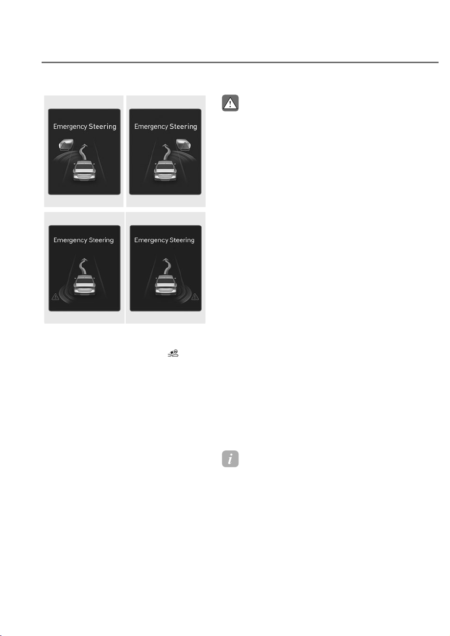
7-16
Driver Assistance System
ORS071105L
ORS071105L
ORS071106L
ORS071106L
ORS073114N
ORS073114N
Emergency Steering
• To warn the driver that emergency
steering will be assisted, the
warning light will blink and the
'Emergency Steering' warning
message will appear on the
instrument cluster. Also, an audible
warning will sound and the steering
wheel will vibrate.
• In emergency steering situation,
steering is assisted by the function to
help prevent a collision with the front-
side vehicle.
• The function will operate when
your vehicle speed is between
approximately 25-90 mph (40-145
km/h) and front-side vehicle and
powered two-wheeler is driving.
CAUTION
• Lane-Change Side function does not
RSHUDWHLIWKHYHKLFOHVSHHGRIWKH
SUHFHGLQJYHKLFOHIURPWKHIURQWVLGH
LVɁPSKɁNPK
• The detecting range of the front
corner radar and the rear corner
UDGDULVGHWHUPLQHGE\DVWDQGDUG
URDGZLGWKWKHUHIRUHRQDQDUURZ
URDG/DQH&KDQJH6LGHIXQFWLRQ
PD\GHWHFWRWKHUYHKLFOHVWZRODQHV
RYHUDQGZDUQ\RX,QFRQWUDVWRQ
DZLGHURDG/DQH&KDQJH6LGH
IXQFWLRQPD\QRWEHDEOHWRGHWHFWD
YHKLFOHGULYLQJLQWKHQH[WODQHDQG
PD\QRWZDUQ\RX
• &ROOLVLRQDYRLGDQFHDVVLVWZLOO
EHFDQFHOHGXQGHUWKHIROORZLQJ
circumstances:
- <RXUYHKLFOHHQWHUVWKHQH[WODQH
E\DFHUWDLQGLVWDQFH
- <RXUYHKLFOHLVDZD\IURPWKH
collision risk
- 7KHVWHHULQJZKHHOLVVKDUSO\
steered
- 7KHEUDNHSHGDOLVGHSUHVVHG
- )RUZDUG&ROOLVLRQDYRLGDQFHDVVLVW
is operating
• After Lane-Change Side function
RSHUDWLRQRUODQHFKDQJH\RXPXVW
GULYHWRWKHFHQWHURIWKHODQH
Lane-Change Side function will not
RSHUDWHLIWKHYHKLFOHLVQRWGULYHQLQ
WKHFHQWHURIWKHODQH
Information
When an additional accident is expected,
Lane- hange Side function will not assist
with steering and only warn the driver of
a collision.
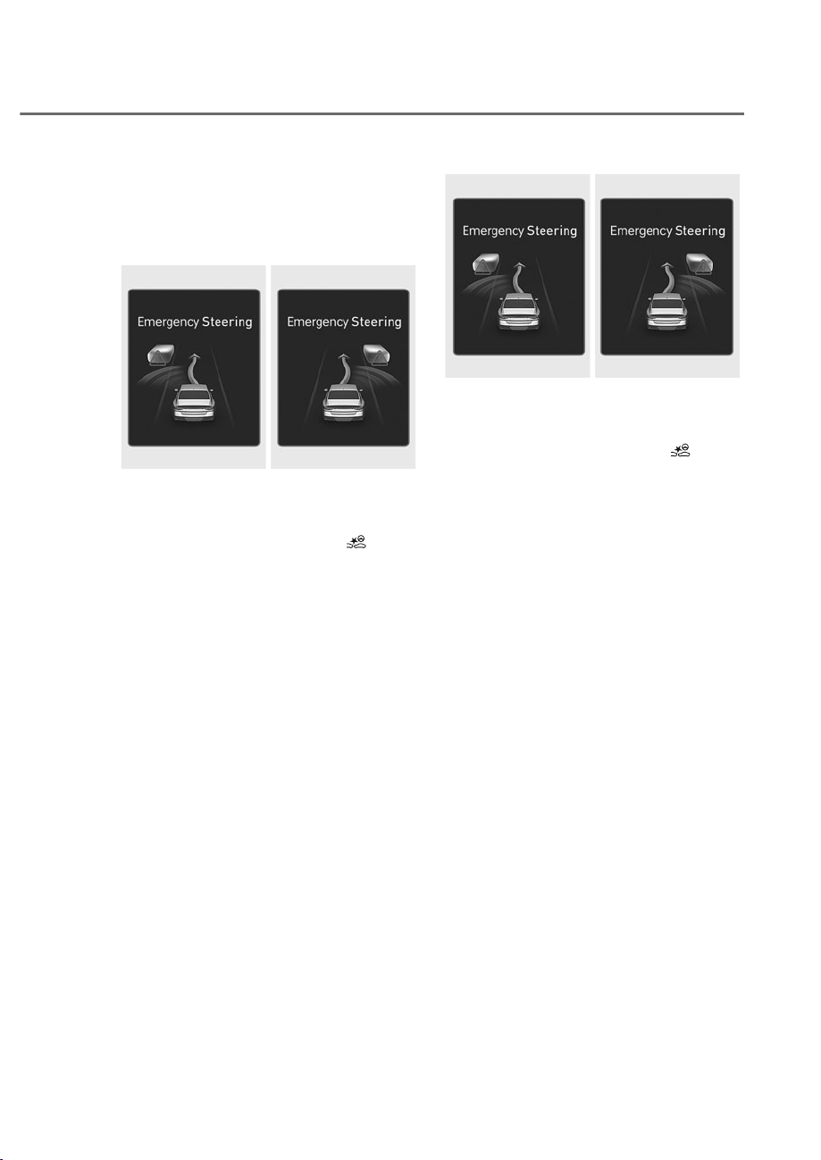
7-17
07
Evasive Steering Assist function
Evasive Steering Assist function will warn
and control the vehicle with ‘Emergency
steering’.
ORS071107L
ORS071107L
ORS071108L
ORS071108L
Emergency Steering (Driver steering
assist)
• To warn the driver that emergency
steering will be assisted, the
warning light will blink and the
'Emergency Steering' warning
message will appear on the
instrument cluster. Also, an audible
warning will sound and the steering
wheel will vibrate.
• If there is a risk of collision with
a vehicle, powered two-wheeler
pedestrian, or cyclist in front, the
steering will be assisted to help
prevent a collision when the driver
steers the vehicle to avoid collision.
• The function will operate when
your vehicle speed is between
approximately 25-53 mph (40-85
km/h).
ORS071107L
ORS071107L
ORS071108L
ORS071108L
Emergency Steering (Evasive steering
assist)
• To warn the driver that emergency
steering will be assisted, the
warning light will blink and the
'Emergency Steering' warning
message will appear on the
instrument cluster. Also, an audible
warning will sound and the steering
wheel will vibrate.
• If there is high risk of collision with a
pedestrian and cyclist in front, and the
vehicle speed to operate emergency
braking is within the operation range,
the steering will be assisted to help
prevent a collision when there is
space to avoid collision in the driving
lane.
• The function will operate when
your vehicle speed is between
approximately 40-47 mph (65-75
km/h).

7-18
Driver Assistance System
CAUTION
• 7KHVWHHULQJZKHHOPD\WXUQ
DXWRPDWLFDOO\ZKHQHPHUJHQF\
VWHHULQJLVRSHUDWLQJ
• (PHUJHQF\VWHHULQJZLOO
DXWRPDWLFDOO\FDQFHOZKHQULVN
IDFWRUVGLVDSSHDU7KHGULYHUPXVW
VWHHUWKHYHKLFOH
• (PHUJHQF\VWHHULQJPD\QRWRSHUDWH
RUPD\FDQFHOGXULQJRSHUDWLRQLI
the steering wheel is held tight or
VWHHUHGLQWKHRSSRVLWHGLUHFWLRQ
• :KHQVWHHULQJLVDVVLVWHGWRDYRLG
FROOLVLRQZLWKDYHKLFOHSRZHUHG
WZRZKHHOHUSHGHVWULDQDQG
F\FOLVWHYDVLYHVWHHULQJDVVLVWZLOO
EHFDQFHOHGLIFROOLVLRQVZLWKRWKHU
REMHFWVYHKLFOHVSRZHUHGWZR
ZKHHOHUSHGHVWULDQVRUF\FOLVWVDUH
H[SHFWHG
• (YDVLYHVWHHULQJDVVLVWPD\QRW
RSHUDWHLIVSDFHWRDYRLGFROOLVLRQLQ
WKHGULYLQJODQHLVLQVXIILFLHQW
• :KHQGULYLQJDWQLJKWWKH
powered two wheeler recognition
SHUIRUPDQFHLVGHJUDGHGVR
)RUZDUG&ROOLVLRQ$YRLGDQFH$VVLVW
PD\EHWHPSRUDULO\OLPLWHGRUPD\
QRWZRUN
Information
For more details on warning messages,
refer to ollision Warning in “Basic
Function”.
WARNING
Take the following precautions when
XVLQJ)RUZDUG&ROOLVLRQ$YRLGDQFH
Assist:
• )RU\RXUVDIHW\RQO\FKDQJHWKH
6HWWLQJVDIWHUSDUNLQJWKHYHKLFOHDWD
VDIHORFDWLRQ
• )RUZDUG&ROOLVLRQ$YRLGDQFH$VVLVW
does not operate in all situations and
FDQQRWDYRLGDOOFROOLVLRQV
• 7KHGULYHUKDVWKHUHVSRQVLELOLW\WR
FRQWUROWKHYHKLFOH'RQRWVROHO\
depend on Forward Collision-
$YRLGDQFH$VVLVW5DWKHUPDLQWDLQ
DVDIHEUDNLQJGLVWDQFHDQGLI
QHFHVVDU\GHSUHVVWKHEUDNHSHGDO
WRUHGXFHGULYLQJVSHHGRUWRVWRS
WKHYHKLFOH
• 1HYHUGHOLEHUDWHO\RSHUDWH)RUZDUG
&ROOLVLRQ$YRLGDQFH$VVLVWRQSHRSOH
REMHFWVHWF,WPD\FDXVHVHULRXV
LQMXU\RUGHDWK
• )RUZDUG&ROOLVLRQ$YRLGDQFH
$VVLVWPD\QRWRSHUDWHLIWKHGULYHU
GHSUHVVHVWKHEUDNHSHGDOWRDYRLGD
FROOLVLRQ

7-19
07
• 'HSHQGLQJRQWKHURDGDQGGULYLQJ
FRQGLWLRQV)RUZDUG&ROOLVLRQ
$YRLGDQFH$VVLVWPD\ZDUQWKHGULYHU
ODWHRUPD\QRWZDUQWKHGULYHU
• 'XULQJ)RUZDUG&ROOLVLRQ$YRLGDQFH
$VVLVWRSHUDWLRQWKHYHKLFOHPD\
VWRSVXGGHQO\LQMXULQJSDVVHQJHUV
DQGVKLIWLQJORRVHREMHFWV$OZD\V
KDYHWKHVHDWEHOWRQDQGNHHSORRVH
REMHFWVVHFXUHG
• ,IDQ\RWKHUV\VWHPȂVZDUQLQJ
PHVVDJHLVGLVSOD\HGRUDXGLEOH
ZDUQLQJLVJHQHUDWHG)RUZDUG
&ROOLVLRQ$YRLGDQFH$VVLVWZDUQLQJ
PHVVDJHPD\QRWEHGLVSOD\HG
DQGDXGLEOHZDUQLQJPD\QRWEH
JHQHUDWHG
• <RXPD\QRWKHDUWKHZDUQLQJVRXQG
RI)RUZDUG&ROOLVLRQ$YRLGDQFH
$VVLVWLIWKHVXUURXQGLQJLVQRLV\
• )RUZDUG&ROOLVLRQ$YRLGDQFH
$VVLVWPD\WXUQRIIRUPD\QRW
RSHUDWHSURSHUO\RUPD\RSHUDWH
XQQHFHVVDULO\GHSHQGLQJRQWKHURDG
FRQGLWLRQVDQGWKHVXUURXQGLQJV
• (YHQLIWKHUHLVDSUREOHPZLWK
)RUZDUG&ROOLVLRQ$YRLGDQFH$VVLVW
WKHYHKLFOHȂVEDVLFEUDNLQJZLOO
IXQFWLRQQRUPDOO\
• 'XULQJHPHUJHQF\EUDNLQJEUDNLQJ
FRQWUROE\)RUZDUG&ROOLVLRQ
$YRLGDQFH$VVLVWZLOODXWRPDWLFDOO\
FDQFHOZKHQWKHGULYHUH[FHVVLYHO\
depresses the accelerator pedal or
VKDUSO\VWHHUVWKHYHKLFOH
CAUTION
• Depending on the condition of the
YHKLFOHSRZHUHGWZRZKHHOHU
SHGHVWULDQDQGF\FOLVWLQIURQWDQG
WKHVXUURXQGLQJVWKHVSHHGUDQJHRU
detecting range to operate Forward
&ROOLVLRQ$YRLGDQFH$VVLVWPD\
UHGXFH)RUZDUG&ROOLVLRQ$YRLGDQFH
$VVLVWPD\RQO\ZDUQWKHGULYHURULW
PD\QRWRSHUDWH
• )RUZDUG&ROOLVLRQ$YRLGDQFH$VVLVW
will operate under certain conditions
E\MXGJLQJWKHULVNOHYHOEDVHGRQ
the condition of the oncoming
YHKLFOHGULYLQJGLUHFWLRQVSHHGDQG
VXUURXQGLQJV
• ,I\RXUYHKLFOHVSHHGLVWRRKLJK
or the speed difference with the
RWKHUYHKLFOHLVWRRODUJH)RUZDUG
&ROOLVLRQ$YRLGDQFH$VVLVWRSHUDWLRQ
PD\EHOLPLWHGRULWPD\QRWRSHUDWH
• When a collision with a surrounding
YHKLFOHLVH[SHFWHG/DQH&KDQJH
2QFRPLQJ/DQH&KDQJH6LGHDQG
(YDVLYH6WHHULQJ$VVLVWZLOOQRWDVVLVW
\RXZLWKVWHHULQJEXWRQO\ZDUQWKH
\RXRIDFROOLVLRQ
Information
• In a situation where a collision is
imminent, braking may be assisted by
Forward ollision-Avoidance Assist
when braking is insufficient by the
driver.
• The images and colors in the
instrument cluster may differ
depending on the cluster type or theme
selected from the settings menu.
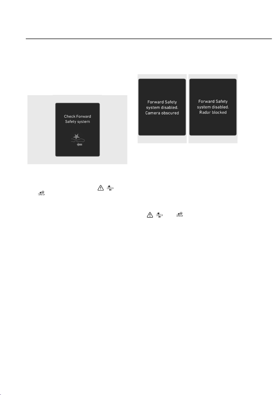
7-20
Driver Assistance System
)RUZDUG&ROOLVLRQ$YRLGDQFH
Assist malfunction and
limitations
Forward Collision-Avoidance Assist
malfunction
OTM070094N
OTM070094N
When Forward Collision-Avoidance
Assist is not working properly, the
'Check Forward Safety system' warning
message will appear, and the
,
,
and
warning lights will illuminate on
the instrument cluster. Have the vehicle
inspected by an authorized retailer of
Genesis Branded products.
Forward Collision-Avoidance Assist
disabled
OJX1079005L
OJX1079005L
OJX1079212L
OJX1079212L
When the front windshield where the
front view camera is located, front radar
cover, bumper or sensor is covered with
foreign material, such as snow or rain, it
can reduce the detecting performance
and temporarily limit or disable Forward
Collision-Avoidance Assist.
If this occurs the ‘Forward Safety
system(s) disabled. Camera obscured’ or
the ‘Forward Safety system(s) disabled.
Radar blocked’ warning message, and
the
,
,
and
warning lights will
illuminate on the instrument cluster.
Forward Collision-Avoidance Assist will
operate properly when snow, rain or
foreign material is removed.
If Forward Collision-Avoidance Assist
does not operate properly after
obstruction (snow, rain, or foreign
material) is removed (including trailer,
carrier, etc., from the rear bumper), have
the vehicle inspected by an authorized
retailer of Genesis Branded products.

7-21
07
WARNING
• (YHQWKRXJKWKHZDUQLQJPHVVDJHRU
warning light does not appear on the
FOXVWHU)RUZDUG&ROOLVLRQ$YRLGDQFH
$VVLVWPD\QRWSURSHUO\RSHUDWH
• )RUZDUG&ROOLVLRQ$YRLGDQFH$VVLVW
PD\QRWSURSHUO\RSHUDWHLQDQDUHD
IRUH[DPSOHRSHQWHUUDLQZKHUH
DQ\REMHFWVDUHQRWGHWHFWHGDIWHU
WXUQLQJ21WKHYHKLFOH
• ,IWKHYHKLFOHLVWXUQHGRIIDQG
restarted while the camera is
EORFNHGRUPDOIXQFWLRQHGWKH
FRQGLWLRQLVPDLQWDLQHG7KHUHIRUH
)RUZDUG&ROOLVLRQ$YRLGDQFH$VVLVWLV
PD\QRWRSHUDWHSURSHUO\
Limitations of Forward Collision-
Avoidance Assist
Forward Collision-Avoidance Assist may
not operate properly, or it may operate
unexpectedly under the following
circumstances:
• The detecting sensor or the
surroundings are contaminated or
damaged
• The temperature around the front
view camera is high or low due to
surrounding environment
• The camera lens is contaminated due
to tinted, filmed or coated windshield,
damaged glass, or sticky foreign
material (sticker, bug, etc.) on the
glass
• Moisture is not removed or frozen on
the windshield
• Washer fluid is continuously sprayed,
or the wiper is on
• Driving in heavy rain or snow, or thick
fog
• The field of view of the front view
camera is obstructed by sun glare
• Street light or light from an oncoming
traffic is reflected on the wet road
surface, such as a puddle on the road
• An object is placed on the dashboard
• Your vehicle is being towed
• The surrounding is very bright
• The surrounding is very dark, such as
in a tunnel, etc.
• The brightness changes suddenly, for
example when entering or exiting a
tunnel
• The brightness outside is low, and the
headlamps are not on or are not bright
• Driving through steam, smoke or
shadow
• Only part of the vehicle, powered
two-wheeler pedestrian or cyclist is
detected
• The vehicle or powered two-wheeler
in front is a bus, heavy truck, truck
with an unusually shaped cargo,
trailer, etc.
• The vehicle or powered two-wheeler
in front has no tail lights, tail lights are
located unusually, etc.
• The brightness outside is low, and the
tail lamps are not on or are not bright
• The rear of the front vehicle is small
or the vehicle does not look normal,
such as when the vehicle is tilted,
overturned, or the side of the vehicle
is visble, etc.
• The front vehicle’s ground clearance is
low or high
• A vehicle, powered two-wheeler,
pedestrian or cyclist suddenly cuts in
front
• The bumper around the front radar is
impacted, damaged or the front radar
is out of position
• The temperature around the front
radar is high or low
• Driving through a tunnel or iron bridge
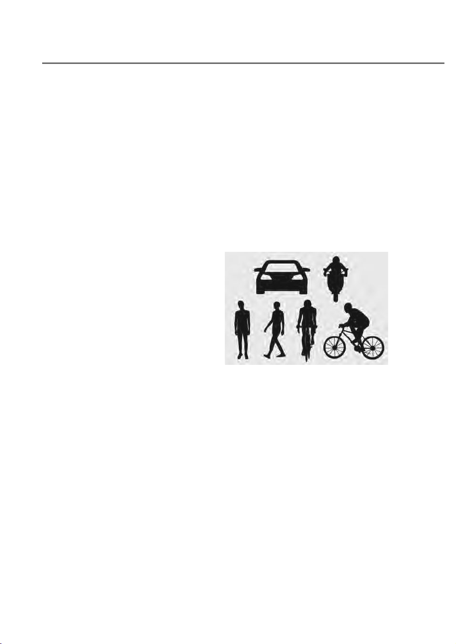
7-22
Driver Assistance System
• Driving in vast areas where there
are few vehicles or structures (for
example, desert, meadow, suburb,
etc.)
• Driving near areas containing metal
substances, such as a construction
zone, railroad, etc.
• A material is near that reflects very
well on the front radar, such as a
guardrail, nearby vehicle, etc.
• The cyclist in front is on a bicycle
made of material that does not reflect
on the front radar
• The vehicle or powered two-wheeler
in front is detected late
• The vehicle or powered two-wheeler
in front is suddenly blocked by an
obstacle
• The vehicle or powered two-wheeler
in front suddenly changes lane or
suddenly reduces speed
• The vehicle or powered two-wheeler
in front is bent out of shape
• The vehicle in front is covered with
snow
• You are departing or returning to the
lane
• Unstable driving
• You are on a roundabout and the
vehicle or powered two-wheeler in
front is not detected
• You are continuously driving in a circle
• The vehicle in front has an unusual
shape
• The vehicle in front is driving uphill or
downhill
• The pedestrian or cyclist is not
fully detected, for example, if the
pedestrian is leaning over or is not
fully walking upright
• The pedestrian or cyclist is wearing
clothing or equipment that makes it
difficult to detect
• Rear wheel steering system (if
equipped) is disabled
ORS071178
ORS071178
The illustration above shows the image
the front view camera and front radar
are capable of detecting as a vehicle,
powered two-wheeler, pedestrian and
cyclist.
• The pedestrian or cyclist in front is
moving very quickly
• The pedestrian or cyclist in front is
short or is posing a low posture
• The pedestrian or cyclist in front has
impaired mobility
• The pedestrian or cyclist in front is
moving intersected with the driving
direction

7-23
07
• There is a group of pedestrians,
cyclists or a large crowd in front
• The pedestrian or cyclist is wearing
clothing that easily blends into the
background, making it difficult to
detect
• The pedestrian or cyclist is difficult to
distinguish from the similarly shaped
structure in the surroundings
• You are driving by a pedestrian,
cyclist, traffic signs, structures, etc.,
near the intersection
• Driving in a parking lot
• Driving through a tollgate,
construction area, unpaved road,
partial paved road, uneven road,
speed bumps, etc.
• Driving on an incline road, curved
road, etc.
• Driving through a roadside with trees
or streetlights
• The adverse road conditions cause
excessive vehicle vibrations while
driving
• Your vehicle height is low or high
due to heavy loads, abnormal tire
pressure, etc.
• Driving through a narrow road where
trees or grass are overgrown
• There is interference by
electromagnetic waves, such as
driving in an area with strong radio
waves or electrical noise
unction rossing, Lane- hange
ncoming, Lane- hange Side, Evasive
Steering Assist function
• The temperature around the front
corner radar or rear corner radar is
high or low
• A trailer or carrier is installed around
the rear corner radar
• The front corner radar or rear corner
radar is covered with snow, rain, dirt,
etc.
• The bumper around the front corner
radar or rear corner radar is covered
with objects, such as a bumper
sticker, bumper guard, bike rack, etc.
• The bumper around the front corner
radar or rear corner radar is impacted,
damaged or the radar is out of
position
• The front corner radar or rear corner
radar is blocked by other vehicles,
walls or pillars
• Driving on a highway ramp or driving
through a tollgate
• Driving on a road where the guardrail
or wall is in double structure
• A vehicle drives very close behind
your vehicle, or a vehicle passes by
your vehicle in close proximity

7-24
Driver Assistance System
• The speed of the other vehicle is very
fast that it passes by your vehicle in a
short time
• Your vehicle passes by another vehicle
• Your vehicle has started at the same
time as the vehicle next to you and
has accelerated
• The vehicle in the next lane moves
two lanes away from you, or when the
vehicle two lanes away moves to the
lane next to you
• A motorcycle or bicycle is detected
• A vehicle such as a flat trailer is
detected
• A large vehicle such as a bus or truck
is detected
• A small moving obstacle such as a
pedestrian, animal, shopping cart or a
baby stroller is detected
• A vehicle with low height such as a
sports car is detected
• The lane is difficult to see due to
foreign material, such as rain, snow,
dust, sand, oil and water puddles
• The color of the lane marking is not
distinguishable from the road
• There are markings on the road near
the lane or the markings on the road
looks similar to the lane markings
• A shadow is casted on the lane
marking by a median strip, trees,
guardrail, noise barriers, etc.
• The lane number increases or
decreases, or the lane markings are
crossing
• There are more than two lane
markings on the road
• The lane markings are complicated or
a structure substitutes for the lines,
such as a construction area
• There are road markings, such as
zigzag lanes, crosswalk markings and
road signs
• The lane suddenly disappears, such as
at the intersection
• The lane is very wide or narrow
• There is a curb or road edges without
a lane
• The vehicle in front is driving with one
side on the lane marking
• The distance to the front vehicle is
extremely close
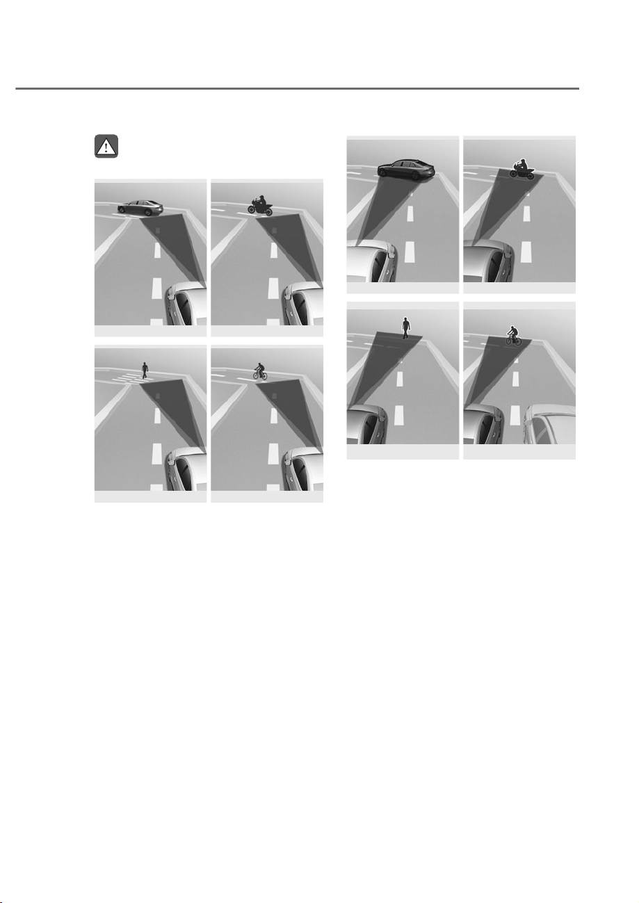
7-25
07
WARNING
• 'ULYLQJRQDFXUYHGURDG
ORS071061
ORS071061
ORS071179
ORS071179
ORS071062
ORS071062
ORS071063
ORS071063
)RUZDUG&ROOLVLRQ$YRLGDQFH$VVLVW
PD\QRWGHWHFWRWKHUYHKLFOHV
SRZHUHGWZRZKHHOHUVSHGHVWULDQV
RUF\FOLVWVLQIURQWRI\RXZKHQ
GULYLQJRQFXUYHGURDGVDGYHUVHO\
affecting the performance of the
VHQVRUV7KLVPD\UHVXOWLQQR
ZDUQLQJEUDNLQJDVVLVWRUVWHHULQJ
DVVLVWZKHQQHFHVVDU\
:KHQGULYLQJRQDFXUYH\RXPXVW
PDLQWDLQDVDIHEUDNLQJGLVWDQFH
DQGLIQHFHVVDU\VWHHUWKHYHKLFOH
DQGGHSUHVVWKHEUDNHSHGDOWR
UHGXFH\RXUGULYLQJVSHHGLQRUGHUWR
PDLQWDLQDVDIHGLVWDQFH
ORS071064
ORS071064
ORS071180
ORS071180
ORS071065
ORS071065
ORS071066
ORS071066
)RUZDUG&ROOLVLRQ$YRLGDQFH$VVLVW
PD\GHWHFWDYHKLFOHSRZHUHGWZR
ZKHHOHUSHGHVWULDQRUF\FOLVWLQWKH
QH[WODQHRURXWVLGHWKHODQHZKHQ
GULYLQJRQDFXUYHGURDG
,IWKLVRFFXUV)RUZDUG&ROOLVLRQ
$YRLGDQFH$VVLVWPD\XQQHFHVVDULO\
ZDUQWKHGULYHUDQGFRQWUROWKHEUDNH
RUVWHHULQJZKHHO$OZD\VFKHFNWKH
WUDIILFFRQGLWLRQVDURXQGWKHYHKLFOH
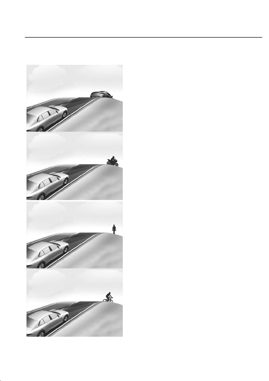
7-26
Driver Assistance System
• 'ULYLQJRQDQLQFOLQHGURDG
ORS071067
ORS071067
ORS071181
ORS071181
ORS071068
ORS071068
ORS071069
ORS071069
)RUZDUG&ROOLVLRQ$YRLGDQFH$VVLVW
PD\QRWGHWHFWRWKHUYHKLFOHV
SRZHUHGWZRZKHHOHUVSHGHVWULDQV
RUF\FOLVWVLQIURQWRI\RXZKLOH
GULYLQJXSKLOORUGRZQKLOODGYHUVHO\
affecting the performance of the
VHQVRUV
7KLVPD\UHVXOWLQXQQHFHVVDU\
ZDUQLQJEUDNLQJDVVLVWRUVWHHULQJ
DVVLVWRUQRZDUQLQJEUDNLQJDVVLVW
RUVWHHULQJDVVLVWLIHTXLSSHGZKHQ
QHFHVVDU\
$OVRYHKLFOHVSHHGPD\UDSLGO\
GHFUHDVHZKHQDYHKLFOHSRZHUHG
WZRZKHHOHUSHGHVWULDQRUF\FOLVW
DKHDGLVVXGGHQO\GHWHFWHG
$OZD\VKDYH\RXUH\HVRQWKHURDG
ZKLOHGULYLQJXSKLOORUGRZQKLOODQG
LIQHFHVVDU\VWHHU\RXUYHKLFOHDQG
GHSUHVVWKHEUDNHSHGDOWRUHGXFH
\RXUGULYLQJVSHHGLQRUGHUWR
PDLQWDLQDVDIHGLVWDQFH
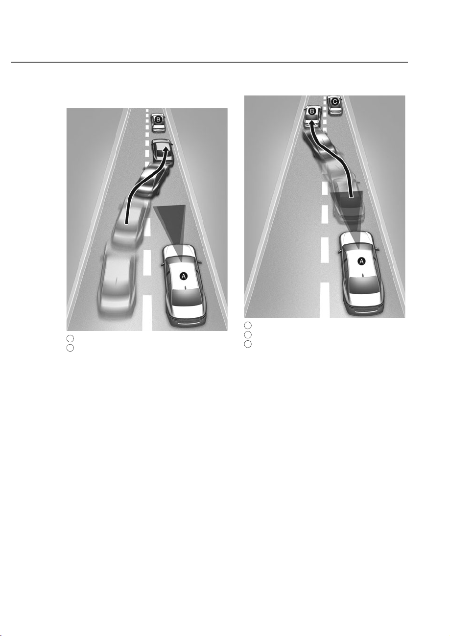
7-27
07
• Changing lanes
ORS071194
ORS071194
A
: Your vehicle,
B
: Lane changing vehicle
:KHQDYHKLFOHPRYHVLQWR\RXUODQH
IURPDQDGMDFHQWODQHLWFDQQRW
EHGHWHFWHGE\WKHVHQVRUXQWLOLW
LVLQWKHVHQVRUVGHWHFWLRQUDQJH
)RUZDUG&ROOLVLRQ$YRLGDQFH$VVLVW
PD\QRWLPPHGLDWHO\GHWHFWWKH
YHKLFOHZKHQWKHYHKLFOHFKDQJHV
ODQHVDEUXSWO\,QWKLVFDVH\RXPXVW
PDLQWDLQDVDIHEUDNLQJGLVWDQFH
DQGLIQHFHVVDU\VWHHU\RXUYHKLFOH
DQGGHSUHVVWKHEUDNHSHGDOWR
UHGXFH\RXUGULYLQJVSHHGLQRUGHUWR
PDLQWDLQDVDIHGLVWDQFH
ORS071195
ORS071195
A
: Your vehicle,
B
: Lane changing vehicle,
C
: Same lane vehicle
:KHQDYHKLFOHLQIURQWRI\RX
PHUJHVRXWRIWKHODQH)RUZDUG
&ROOLVLRQ$YRLGDQFH$VVLVWPD\QRW
LPPHGLDWHO\GHWHFWWKHYHKLFOHWKDW
LVQRZLQIURQWRI\RX,QWKLVFDVH
\RXPXVWPDLQWDLQDVDIHEUDNLQJ
GLVWDQFHDQGLIQHFHVVDU\VWHHU\RXU
YHKLFOHDQGGHSUHVVWKHEUDNHSHGDO
WRUHGXFH\RXUGULYLQJVSHHGLQRUGHU
WRPDLQWDLQDVDIHGLVWDQFH
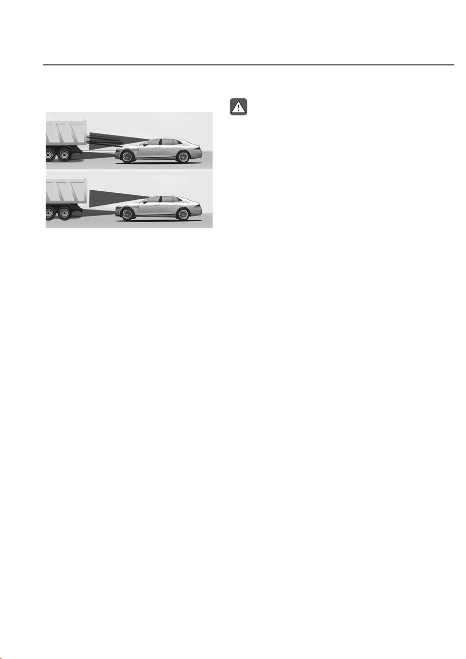
7-28
Driver Assistance System
• 'HWHFWLQJYHKLFOH
ORS071047
ORS071047
,IWKHYHKLFOHLQIURQWRI\RXKDV
FDUJRWKDWH[WHQGVUHDUZDUGIURP
WKHFDERUZKHQWKHYHKLFOHLQIURQW
RI\RXKDVKLJKHUJURXQGFOHDUDQFH
additional special attention is
UHTXLUHG)RUZDUG&ROOLVLRQ
$YRLGDQFH$VVLVWPD\QRWEHDEOH
WRGHWHFWWKHFDUJRH[WHQGLQJIURP
WKHYHKLFOH,QWKHVHLQVWDQFHV
\RXPXVWPDLQWDLQDVDIHEUDNLQJ
GLVWDQFHIURPWKHUHDUPRVWREMHFW
DQGLIQHFHVVDU\VWHHU\RXUYHKLFOH
DQGGHSUHVVWKHEUDNHSHGDOWR
UHGXFH\RXUGULYLQJVSHHGLQRUGHUWR
PDLQWDLQGLVWDQFH
WARNING
• :KHQ\RXDUHWRZLQJDWUDLOHURU
DQRWKHUYHKLFOHWXUQRII)RUZDUG
&ROOLVLRQ$YRLGDQFH$VVLVWIRUVDIHW\
UHDVRQV
• )RUZDUG&ROOLVLRQ$YRLGDQFH$VVLVW
PD\RSHUDWHLIREMHFWVWKDWDUH
similar in shape or characteristics
WRYHKLFOHVSRZHUHGWZRZKHHOHUV
SHGHVWULDQVDQGF\FOLVWVDUH
GHWHFWHG
• )RUZDUG&ROOLVLRQ$YRLGDQFH$VVLVW
GRHVQRWRSHUDWHRQELF\FOHVRU
VPDOOHUZKHHOHGREMHFWVVXFKDV
OXJJDJHEDJVVKRSSLQJFDUWVRU
VWUROOHUV
• )RUZDUG&ROOLVLRQ$YRLGDQFH
$VVLVWPD\QRWRSHUDWHSURSHUO\LI
LQWHUIHUHGE\VWURQJHOHFWURPDJQHWLF
ZDYHV
• )RUZDUG&ROOLVLRQ$YRLGDQFH$VVLVW
PD\QRWRSHUDWHIRUȸȼVHFRQGVDIWHU
WKHYHKLFOHLVVWDUWHGRUWKHIURQW
YLHZFDPHUDLVLQLWLDOL]HG

7-29
07
Information
This device complies with Part 15 of the
F rules. peration is sub ect to the
following three conditions:
1. This device may not cause harmful
interference, and
2. This device must accept any
interference received, including
interference that may cause undesired
operation.
3. hanges or modifications not expressly
approved by the party responsible
for compliance could void the user’s
authority to operate the device.
Information
Radio frequency radiation exposure
information:
This equipment complies with F
radiation exposure limits set forth for an
uncontrolled environment.This equipment
should be installed and operated with
minimum distance of 8 in. (20 cm) between
the radiator (antenna) and your body.
This transmitter must not be co-located or
operating in con unction with any other
antenna or transmitter.
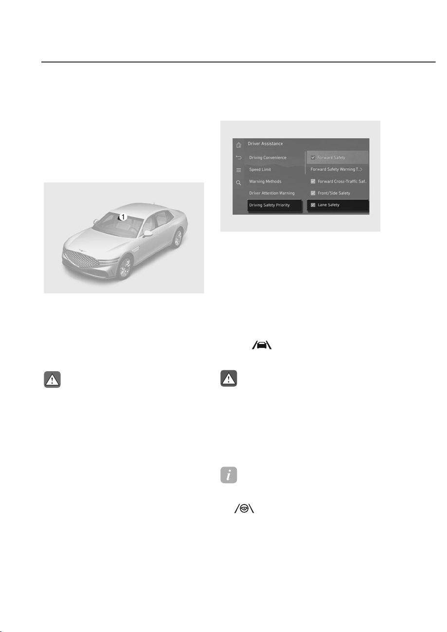
7-30
Driver Assistance System
/$1(.((3,1*$66,67ʚ/.$ʛ
While driving over a certain speed,
Lane Keeping Assist helps detect lane
markings (or road edges) and may
warn you if your vehicle leaves the lane
without using the turn signal and may
assist with steering to help prevent your
vehicle departing from its travel lane.
Detecting sensor
ORS071001
ORS071001
M: Front view camera
The front view camera is used as a
detecting sensor to detect lane markings
(or road edges).
Refer to the picture above for the
detailed location of the detecting sensor.
CAUTION
For more details on the precautions
RIWKHIURQWYLHZFDPHUDUHIHUWR
ȃ)RUZDUG&ROOLVLRQ$YRLGDQFH$VVLVW
)&$ȄVHFWLRQLQWKLVFKDSWHU
/DQH.HHSLQJ$VVLVW6HWWLQJV
Lane Safety
ORS073229N
ORS073229N
With the engine on, select select 'Driver
$VVLVWDQFHɌ'ULYLQJ6DIHW\Ɍ/DQH
Safety' from the settings menu in the
infotainment system to set whether to
use the function.
If 'Lane Safety' is selected, Lane Keeping
Assist automatically assists the driver’s
steering when lane departure is detected
to help prevent the vehicle from
moving out of its lane. If 'Lane Safety' is
deselectd, Lane Keeping Assist turns off
and the
indicator light turns off on
the cluster.
WARNING
• /DQH.HHSLQJ$VVLVWGRHVQRWFRQWURO
WKHVWHHULQJZKHHOZKHQWKHYHKLFOH
LVGULYHQLQWKHPLGGOHRIWKHODQH
• 7KHGULYHUVKRXOGDOZD\VEHDZDUH
RIWKHVXUURXQGLQJV,I/DQH6DIHW\
LVGHVHOHFWHG/DQH.HHSLQJ$VVLVW
FDQQRWDVVLVW\RX
Information
• If you turn off Lane Keeping Assist
by pressing the Lane Driving Assist
(
) button on the steering wheel,
Lane safety setting also turns off.
• If the engine is restarted, Lane Keeping
Assist will maintain the last setting.
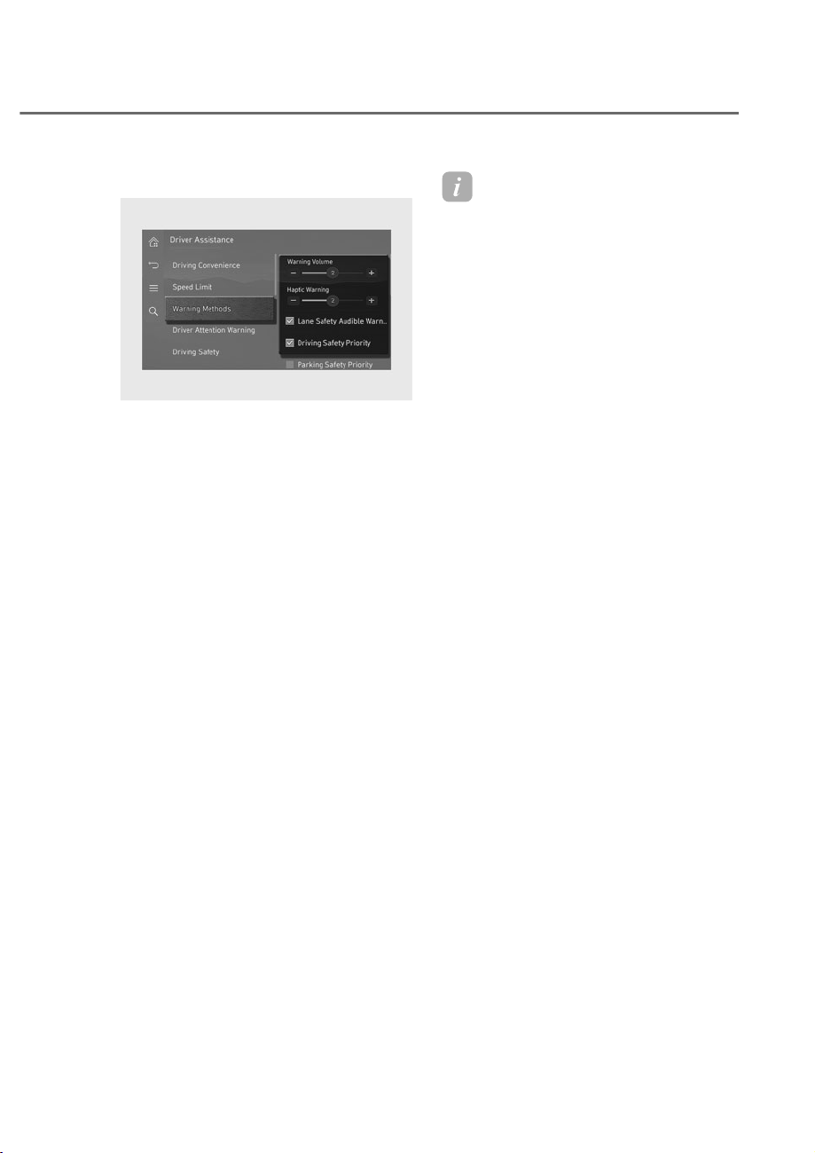
7-31
07
Warning methods
ORS073340N
ORS073340N
With the engine on, go to 'Driver
$VVLVWDQFHɌ:DUQLQJ0HWKRGVIURPWKH
Settings in the infotainment system to
select the following:
• Warning Volume: The warning volume
can be adjusted. If you turn off the
Warning Volume, for your safety, the
function may warn you with a low
volume.
• Haptic Warning: The steering wheel
vibration can be set.
• Lane Safety Audible Warning Off: The
warning volume of Lane Safety does
not sound when Haptic Warning is
adjusted between 1 to 3.
• Driving Safety Priority: Your vehicle
lowers all other audio volumes when
the Driver Assistance system warning
sounds.
Information
• If you change the Warning Methods,
Warning Methods of other Driver
Assistance systems may change.
• Warning Method will maintain its last
setting even if the vehicle is restarted.
• The setting menu may not be available
for your vehicle depending on the
vehicle features and specifications.
• The Warning olume and Haptic
Warning cannot be turned off at the
same time. When one of the warning is
turned off the other is activated.
• 'Lane Safety Audible Warning ff' can
be set when both the 'Warning olume'
and the 'Haptic Warning' are on.
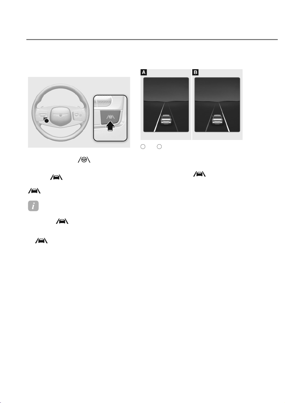
7-32
Driver Assistance System
.HHSLQJ$VVLVW2SHUDWLRQ
Turning Lane Keeping Assist On/Off
ORS071024
ORS071024
With the engine on, press and hold the
Lane Driving Assist (
) button located
on the steering wheel to turn on and off.
When Lane Keeping Assist is on, the gray
or green
indicator illuminates.
When Lane Keeping Assist is off, the
indicator turns off.
Information
• When Lane Keeping Assist is ready to
operate,
indicator turns gray on
the cluster.
• When Lane Keeping Assist is operating,
indicator turns green on the
cluster.
Warning and control
ORS072110N
ORS072110N
A
: Left,
B
: Right
Lane Departure Warning
• To warn the driver that the vehicle
is departing from the projected lane
in front, the green
indicator
light will blink on the instrument
cluster, the lane line will blink on the
instrument cluster depending on
which direction the vehicle is veering,
and an audible warning will sound.
Also, the steering wheel will vibrate.
• Lane Departure Warning will operate
when your vehicle speed is between
approximately 40-120 mph (60-200
km).
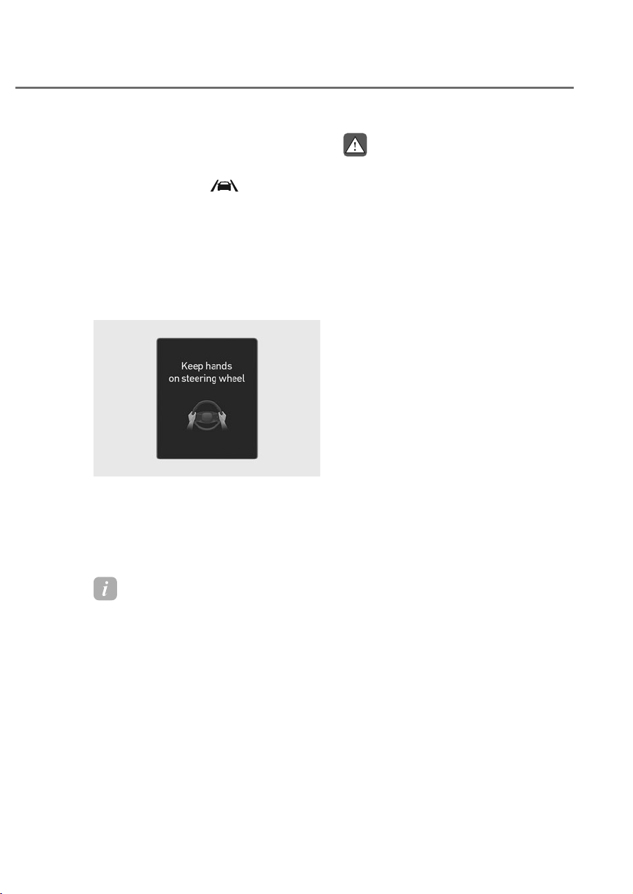
7-33
07
Lane Keeping Assist
• To warn the driver that the vehicle
is departing from the projected lane
in front, the green
indicator
light will blink on the cluster, and the
steering wheel will make adjustments
to keep vehicle inside the lane.
• Lane Keeping Assist will operate
when your vehicle speed is between
approximately 40-120 mph (60-200
km).
Hands-off warning
ORS071109L
ORS071109L
If the driver takes their hands off the
steering wheel for several seconds, the
‘Keep hands on steering wheel’ warning
message will appear on the instrument
cluster, and an audible warning will
sound in stages.
Information
For more details on precautions of the
steering wheel grip sensor, refer to
"Steering Wheel Grip Sensor" section in
chapter 5.
WARNING
• 7KHVWHHULQJZKHHOPD\QRWEH
assisted if the steering wheel is held
YHU\WLJKWRUWKHVWHHULQJZKHHOLV
VWHHUHGRYHUDFHUWDLQGHJUHH
• /DQH.HHSLQJ$VVLVWGRHVQRWRSHUDWH
DWDOOWLPHV,WLVWKHUHVSRQVLELOLW\RI
WKHGULYHUWRVDIHO\VWHHUWKHYHKLFOH
DQGWRPDLQWDLQWKHYHKLFOHLQLWV
ODQH
• The hands–off warning message
PD\DSSHDUODWHGHSHQGLQJRQURDG
FRQGLWLRQV$OZD\VKDYH\RXUKDQGV
RQWKHVWHHULQJZKHHOZKLOHGULYLQJ
• ,IWKHVWHHULQJZKHHOLVKHOGYHU\
OLJKWO\WKHKDQGVǸRIIZDUQLQJ
PHVVDJHPD\DSSHDUEHFDXVH/DQH
.HHSLQJ$VVLVWPD\QRWUHFRJQL]H
WKDWWKHGULYHUKDVWKHLUKDQGVRQWKH
VWHHULQJZKHHO
• ,I\RXDWWDFKREMHFWVWRWKHVWHHULQJ
ZKHHOWKHKDQGVRIIZDUQLQJPD\
QRWZRUNSURSHUO\
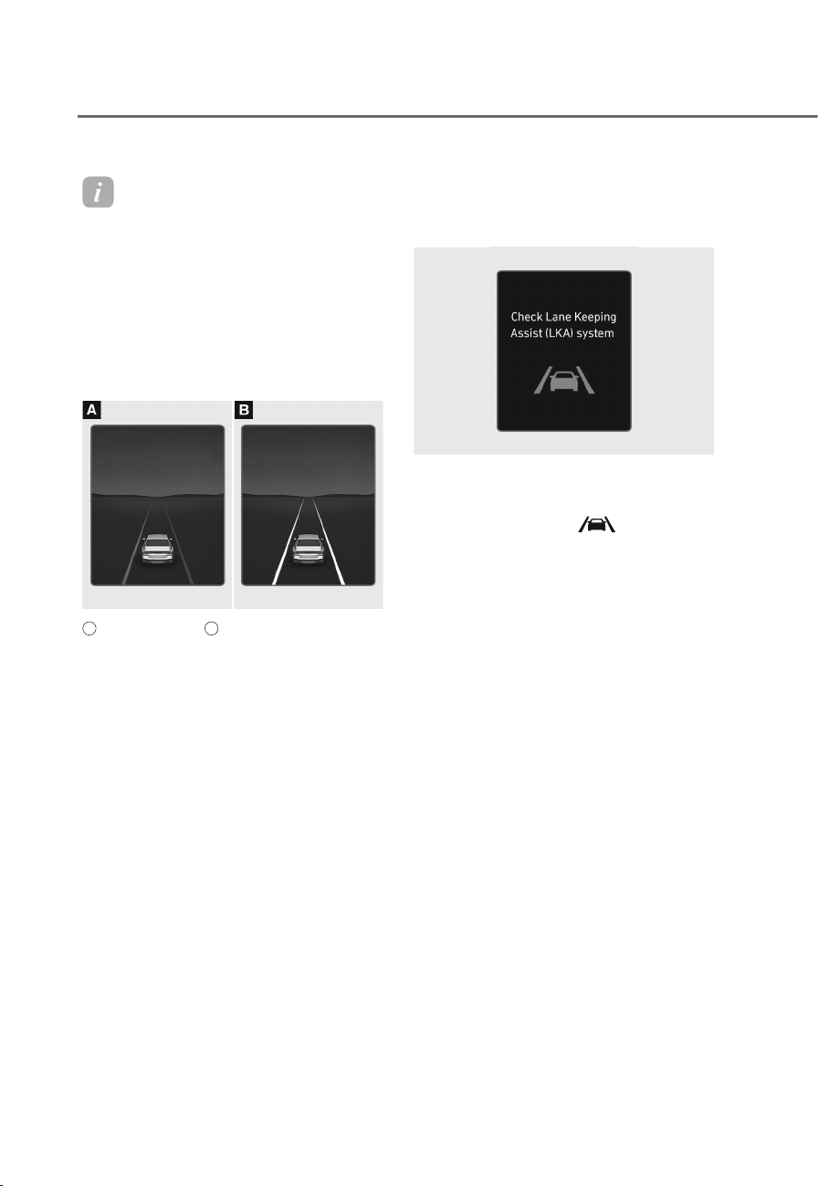
7-34
Driver Assistance System
Information
• For more details on instrument cluster
settings, refer to “L D display control”
section in chapter 4.
• When lane markings (or road edges)
are detected, the lane lines on the
cluster will change from grey to white.
• When the lane markings (or road
edges) are detected and Highway Lane
hange Assist is on, the lane lines on
the cluster may change to green.
ORS072112N
ORS072112N
A
: Lane undetected,
B
: Lane detected
• The images and colors in the
instrument cluster may differ
depending on the cluster type or theme
selected from the settings menu.
• Even though the steering is assisted by
Lane Keeping Assist, the driver may
control the steering wheel.
• The steering wheel may feel heavier
or lighter when the steering wheel is
assisted by Lane Keeping Assist than
when it is not.
/DQH.HHSLQJ$VVLVW0DOIXQFWLRQ
and Limitations
Lane Keeping Assist malfunction
ORG3EV071192L
ORG3EV071192L
When Lane Keeping Assist is not working
properly, the ‘Check Lane Keeping Assist
(LKA) system’ warning message will
appear and the yellow
indicator
light will illuminate on the instrument
cluster. If this occurs, have the vehicle
inspected by an authorized retailer of
Genesis Branded products.
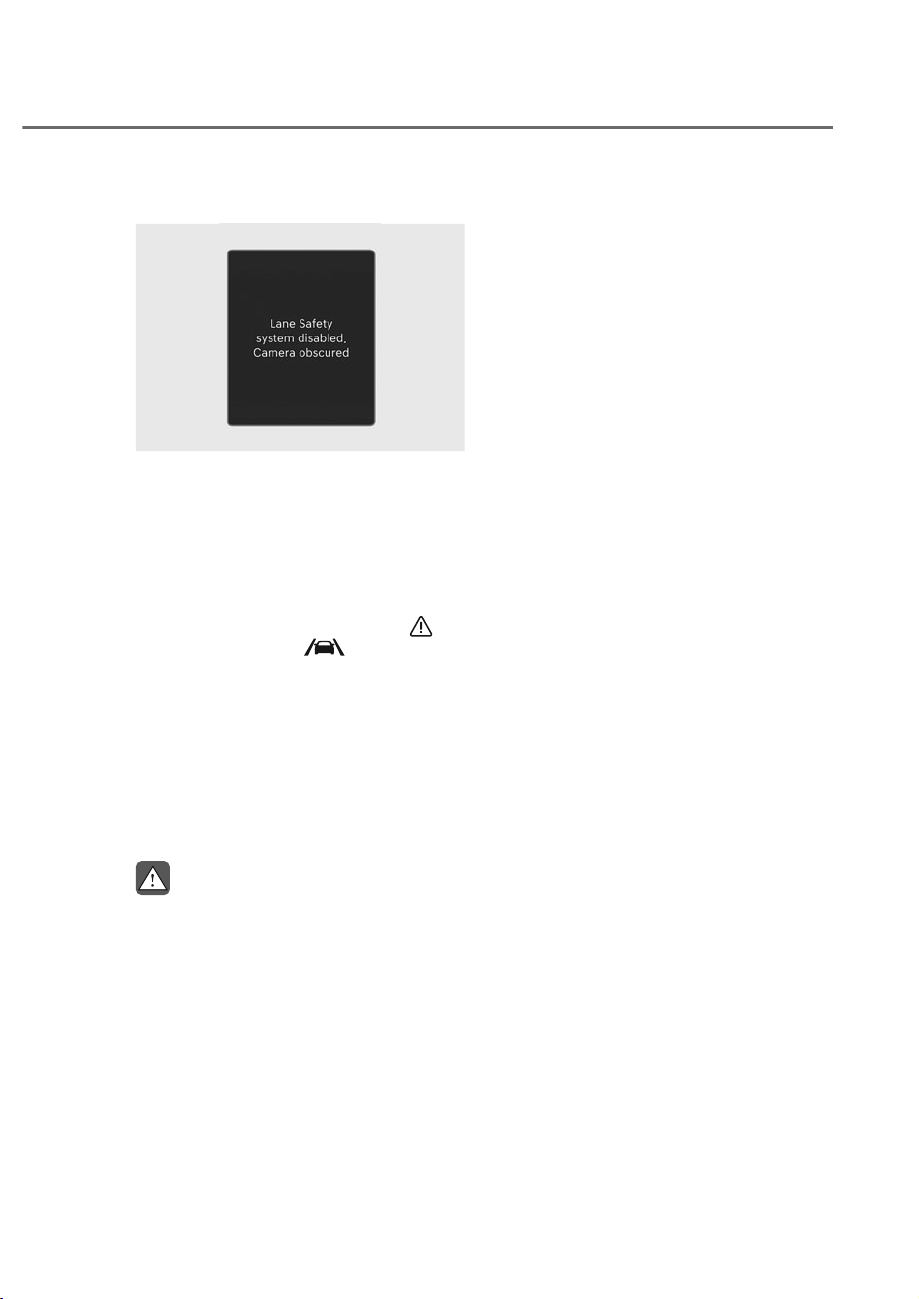
7-35
07
Lane Keeping Assist disabled
ORS073332N
ORS073332N
When the front windshield where the
front view camera is located, or sensor
is covered with foreign material, such as
snow or rain, it can reduce the detecting
performance and temporarily limit or
disable Lane Keeping Assist.
If this occurs, the 'Driver Assistance
system limited. Camera obscured'
warning message and the master (
) or
Lane Keeping Assist (
) warning light
appears on the instrument cluster.
Lane Keeping Assist operates properly
when snow, rain or foreign material is
removed.
If Lane Keeping Assist does not
operate properly after it is removed,
we recommend that your vehicle be
inspected by an authorized retailer of
Genesis Branded products.
WARNING
• (YHQWKRXJKWKHZDUQLQJPHVVDJH
does not appear on the instrument
FOXVWHU/DQH.HHSLQJ$VVLVWPD\QRW
SURSHUO\RSHUDWH
• ,IWKHYHKLFOHLVWXUQHGRIIDQG
restarted while the camera is
EORFNHGRUPDOIXQFWLRQHGWKH
FRQGLWLRQLVPDLQWDLQHG7KHUHIRUH
/DQH.HHSLQJ$VVLVWPD\QRWRSHUDWH
SURSHUO\
Limitations of Lane Keeping Assist
Lane Keeping Assist may not operate
properly or may operate unexpectedly
under the following circumstances:
• The lane is contaminated or difficult
to detect because:
- The lane markings (or road edge)
are covered with rain, snow, dirt,
oil, etc.
- The color of the lane marking (or
road edge) is not distinguishable
from the road
- There are markings (or road
edges) on the road near the lane
or the markings (or road edges) on
the road look similar to the lane
markings (or road edge)
- The lane marking (or road edge) is
indistinct or damaged
- The shadow is on the lane marking
(or road edge) by a median strip,
trees, guardrail, noise barriers, etc.
• The lane number increases or
decreases, or the lane markings (or
road edges) are crossing
• There are more than two lane
markings (or road edges) on the road
• The lane markings (or road edges) are
complicated or a structure substitutes
for the lines, such as a construction
area
• There are road markings, such as
zigzag lanes, crosswalk markings and
road signs
• The lane suddenly disappears, such as
at the intersection
• The lane (or road width) is very wide
or narrow

7-36
Driver Assistance System
• There is a road edge without a lane
• There is a boundary structure in the
roadway, such as a tollgate, sidewalk,
curb, etc.
• The distance to the front vehicle is
extremely short or the vehicle in front
is covering the lane marking (or road
edge)
• Rear wheel steering system (if
equipped) is disabled
Information
For more details on the limitations of the
front view camera, refer to “Forward
ollision-Avoidance Assist (F A)” section
in this chapter.
WARNING
Take the following precautions when
XVLQJ/DQH.HHSLQJ$VVLVW
• 7KHGULYHUKDVWKHUHVSRQVLELOLW\WR
VDIHO\GULYHDQGFRQWUROWKHYHKLFOH
'RQRWVROHO\UHO\RQ/DQH.HHSLQJ
$VVLVWDQGGULYHGDQJHURXVO\
• 7KHRSHUDWLRQRI/DQH.HHSLQJ$VVLVW
FDQEHFDQFHOHGRUQRWZRUNSURSHUO\
depending on road conditions and
VXUURXQGLQJV$OZD\VEHFDXWLRXV
ZKLOHGULYLQJ
• 5HIHUWRȃ/LPLWDWLRQVRI/DQH.HHSLQJ
$VVLVWȄLIWKHODQHLVQRWGHWHFWHG
SURSHUO\
• :KHQ\RXDUHWRZLQJDWUDLOHURU
DQRWKHUYHKLFOHWXUQRII/DQH
.HHSLQJ$VVLVWIRUVDIHW\UHDVRQV
• ,IWKHYHKLFOHLVGULYHQDWKLJKVSHHG
WKHVWHHULQJZKHHOZLOOQRWEH
FRQWUROOHG7KHGULYHUPXVWDOZD\V
follow the speed limit when using
/DQH.HHSLQJ$VVLVW
• ,IDQ\RWKHUV\VWHPȂVZDUQLQJ
PHVVDJHLVGLVSOD\HGRUDXGLEOH
ZDUQLQJLVJHQHUDWHG/DQH.HHSLQJ
$VVLVWZDUQLQJPHVVDJHPD\QRWEH
GLVSOD\HGDQGDXGLEOHZDUQLQJPD\
QRWEHJHQHUDWHG
• <RXPD\QRWKHDUWKHZDUQLQJ
VRXQGRI/DQH.HHSLQJ$VVLVWLIWKH
VXUURXQGLQJLVQRLV\
• ,I\RXDWWDFKREMHFWVWRWKHVWHHULQJ
ZKHHOVWHHULQJPD\QRWEHDVVLVWHG
SURSHUO\
• /DQH.HHSLQJ$VVLVWPD\QRWRSHUDWH
IRUȸȼVHFRQGVDIWHUWKHYHKLFOHLV
VWDUWHGRUWKHIURQWYLHZFDPHUDLV
LQLWLDOL]HG
• /DQH.HHSLQJ$VVLVWZLOOQRWRSHUDWH
when:
- Within a certain period of time
right after turning on or off the
WXUQVLJQDORUKD]DUGZDUQLQJ
IODVKHU
- 7KHYHKLFOHLVQRWGULYHQLQWKH
center of the lane when Lane
.HHSLQJ$VVLVWLVWXUQHGRQRUULJKW
DIWHUFKDQJLQJDODQH
- (6&(OHFWURQLF6WDELOLW\&RQWURO
RU9609HKLFOH6WDELOLW\
0DQDJHPHQWLVDFWLYDWHG
- 7KHYHKLFOHLVGULYHQRQDVKDUS
FXUYH
- 9HKLFOHVSHHGLVEHORZȺȼPSKȼȼ
NPRUDERYHȸȺɁPSKȹȸɁNP
- 7KHYHKLFOHPDNHVVXGGHQODQH
FKDQJHV
- 7KHYHKLFOHEUDNHVVXGGHQO\
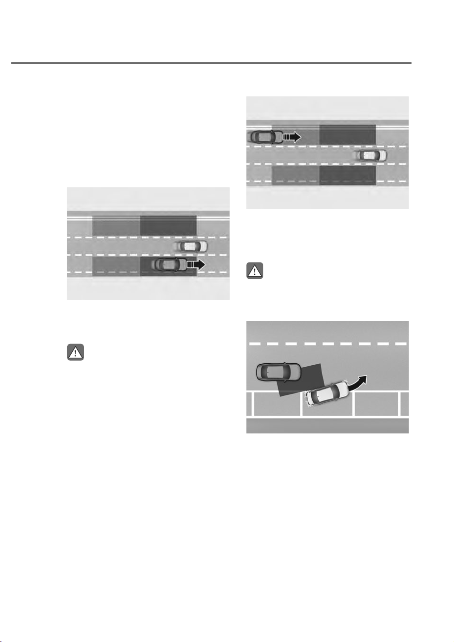
7-37
07
%/,1'ʏ6327&2//,6,21ʏ$92,'$1&($66,67ʚ%&$ʛ
Blind-Spot Collision-Avoidance Assist
helps detect approaching vehicles in the
driver’s blind spot areas and warn you of
a possible collision with a warning light
and a warning sound.
If there is a collision risk when exiting
a parallel space, Blind-Spot Collision-
Avoidance Assist may assist with braking
your vehicle to help avoid a collision.
ORS071039
ORS071039
Blind-Spot Collision-Avoidance Assist
helps detect and informs the driver that a
vehicle is in the blind spot.
CAUTION
7KHGHWHFWLQJUDQJHPD\YDU\
GHSHQGLQJRQWKHVSHHGRI\RXU
YHKLFOH(YHQLIWKHUHLVDYHKLFOHLQWKH
EOLQGVSRWDUHD%OLQG6SRW&ROOLVLRQ
$YRLGDQFH$VVLVWPD\QRWZDUQ\RX
ZKHQ\RXSDVVE\DWKLJKVSHHGV
ORS071040
ORS071040
Blind-Spot Collision-Avoidance Assist
helps detect and informs the driver that
a vehicle is approaching at high speed
from the blind spot area.
CAUTION
:DUQLQJWLPLQJPD\YDU\GHSHQGLQJRQ
WKHVSHHGRIWKHYHKLFOHDSSURDFKLQJDW
KLJKVSHHG
ORS071042
ORS071042
When you are driving forward out of a
parking space, if Blind-Spot Collision-
Avoidance Assist judges that there is
a collision risk with an approaching
vehicle in the blind spot, it can help avoid
collision by applying the brake.

7-38
Driver Assistance System
Detecting sensor
ORS071005
ORS071005
M: Rear corner radar
Refer to the picture above for the
detailed location of the detecting
sensors.
CAUTION
Take the following precautions to
maintain optimal performance of the
detecting sensor:
• 1HYHUGLVDVVHPEOHWKHGHWHFWLQJ
VHQVRUDVVHPEO\RUFDXVHDQ\
GDPDJHWRLW
• If the detecting sensor or the area
WKHVHQVRUKDVEHHQGDPDJHGRU
LPSDFWHGLQDQ\ZD\HYHQWKRXJK
the warning message does not
DSSHDURQWKHFOXVWHU%OLQG6SRW
&ROOLVLRQ$YRLGDQFH$VVLVWPD\QRW
RSHUDWHSURSHUO\+DYHWKHYHKLFOH
LQVSHFWHGE\DQDXWKRUL]HGUHWDLOHURI
*HQHVLV%UDQGHGSURGXFWV
• ,IWKHGHWHFWLQJVHQVRUVKDYHEHHQ
UHSODFHGRUUHSDLUHGKDYHWKH
YHKLFOHLQVSHFWHGE\DQDXWKRUL]HG
UHWDLOHURI*HQHVLV%UDQGHGSURGXFWV
• 8VHRQO\JHQXLQHSDUWVWRUHSDLUWKH
IURQWEXPSHURUUHDUEXPSHUZKHUH
WKHUHDUFRUQHUUDGDULVORFDWHG
• 'RQRWDSSO\OLFHQVHSODWHIUDPHRU
REMHFWVVXFKDVDEXPSHUVWLFNHU
ILOPRUDEXPSHUJXDUGQHDUWKHUHDU
FRUQHUUDGDU
• %OLQG6SRW&ROOLVLRQ$YRLGDQFH
$VVLVWPD\QRWZRUNSURSHUO\LIWKH
EXPSHUKDVEHHQUHSODFHGRUWKH
surroundings of the rear corner radar
KDVEHHQGDPDJHGRUSDLQWKDVEHHQ
DSSOLHG
• ,IDWUDLOHUFDUULHUHWFLVLQVWDOOHG
LWPD\DGYHUVHO\DIIHFWWKH
performance of the rear corner radar
RU%OLQG6SRW&ROOLVLRQ$YRLGDQFH
$VVLVWPD\QRWRSHUDWH
• For more details on the precautions
RIWKHIURQWYLHZFDPHUDUHIHUWR
ȃ)RUZDUG&ROOLVLRQ$YRLGDQFH$VVLVW
)&$ȄVHFWLRQLQWKLVFKDSWHU

7-39
07
%OLQG6SRW&ROOLVLRQ$YRLGDQFH
Assist Settings
Blind-Spot Safety
With the engine on, select 'Driver
$VVLVWDQFHɌ'ULYLQJ6DIHW\Ɍ%OLQG6SRW
Safety' from the settings menu to set
whether to use each function.
• If 'Blind-Spot Safety' is selected, Blind-
Spot Collision-Avoidance Assist warns
the driver with a warning message,
an audible warning depending on the
collision risk levels. Braking assist is
applied for parking exit depending on
the collision risk levels.
OTM070097N
OTM070097N
When the engine is restarted with Blind-
Spot Collision-Avoidance Assist off,
the ‘Blind-Spot Safety System is Off’
message will appear on the instrument
cluster.
If you change the setting from ‘Off’ to
‘Active Assist’ or ‘Warning Only’, the
warning light on the side view mirror will
blink for three seconds.
In addition, if the engine is turned on,
when Blind-Spot Collision-Avoidance
Assist is set to ‘Active Assist’ or ‘Warning
Only’, the warning light on the side view
mirror will blink for three seconds.
WARNING
,Iȁ%OLQG6SRW6DIHW\ȂLVGHVHOHFWHG
%OLQGVSRW&ROOLVLRQ$YRLGDQFH$VVLVW
FDQQRWDVVLVW\RX
Information
If the engine is restarted, Blind-Spot
ollision-Avoidance Assist will maintain
the last setting.
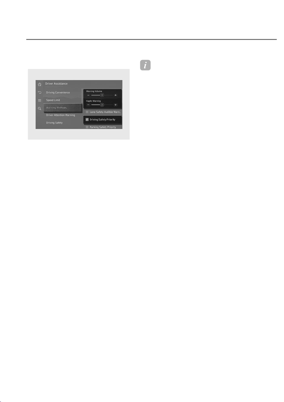
7-40
Driver Assistance System
Warning methods
ORS073334N
ORS073334N
With the engine on, go to 'Driver
$VVLVWDQFHɌ:DUQLQJ0HWKRGVIURPWKH
Settings in the infotainment system to
select the following:
• Warning Volume: The warning volume
can be adjusted.
• Haptic Warning: The steering wheel
vibration can be set.
• Driving Safety Priority: Your vehicle
lowers all other audio volumes when
the Driver Assistance system warning
sounds.
Information
• If you change the Warning Methods,
Warning Methods of other Driver
Assistance systems may change.
• Warning Method will maintain its last
setting even if the vehicle is restarted.
• The setting menu may not be available
for your vehicle depending on the
vehicle features and specifications.
• The Warning olume and Haptic
Warning cannot be turned off at the
same time. When one of the warning is
turned off the other is activated.
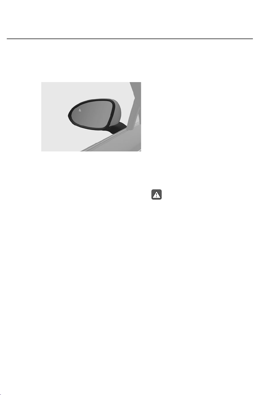
7-41
07
%OLQG6SRW&ROOLVLRQ$YRLGDQFH
Assist Operation
Vehicle detection
ORS071235
ORS071235
• To warn the driver a vehicle is
detected, the warning light on the
side view mirror and head-up display
will illuminate.
• Vehicle detection will operate when
your vehicle speed is above 12 mph
(20 km/h) and the speed of the vehicle
in the blind spot area is above 7 mph
(10 km/h).
Collision warning
• Collision warning will operate when
the turn signal is turned on in the
direction of the detected vehicle.
• To warn the driver of a collision, the
warning light on the side view mirror
and head-up display will blink. At the
same time, an audible warning will
sound, and the steering wheel will
vibrate.
• Collision warning will operate when
your vehicle speed is above 24 mph
(40 km/h) and the speed of the vehicle
in the blind spot area is above 7 mph
(10 km/h).
• When the turn signal is turned off or
you move away from the lane, the
collision warning will be canceled and
Blind-Spot Collision-Avoidance Assist
will return to vehicle detection state.
WARNING
• The detecting range of the front
corner radar or rear corner radar
LVGHWHUPLQHGE\DVWDQGDUGURDG
ZLGWKWKHUHIRUHRQDQDUURZURDG
%OLQG6SRW&ROOLVLRQ$YRLGDQFH
$VVLVWPD\GHWHFWRWKHUYHKLFOHV
LQWZRODQHVRYHUDQGZDUQ\RX,Q
FRQWUDVWRQDZLGHURDG%OLQG6SRW
&ROOLVLRQ$YRLGDQFH$VVLVWPD\QRW
EHDEOHWRGHWHFWDYHKLFOHGULYLQJLQ
WKHQH[WODQHDQGPD\QRWZDUQ\RX
• :KHQWKHKD]DUGZDUQLQJIODVKHULV
RQWKHFROOLVLRQZDUQLQJE\WKHWXUQ
VLJQDOZLOOQRWRSHUDWH
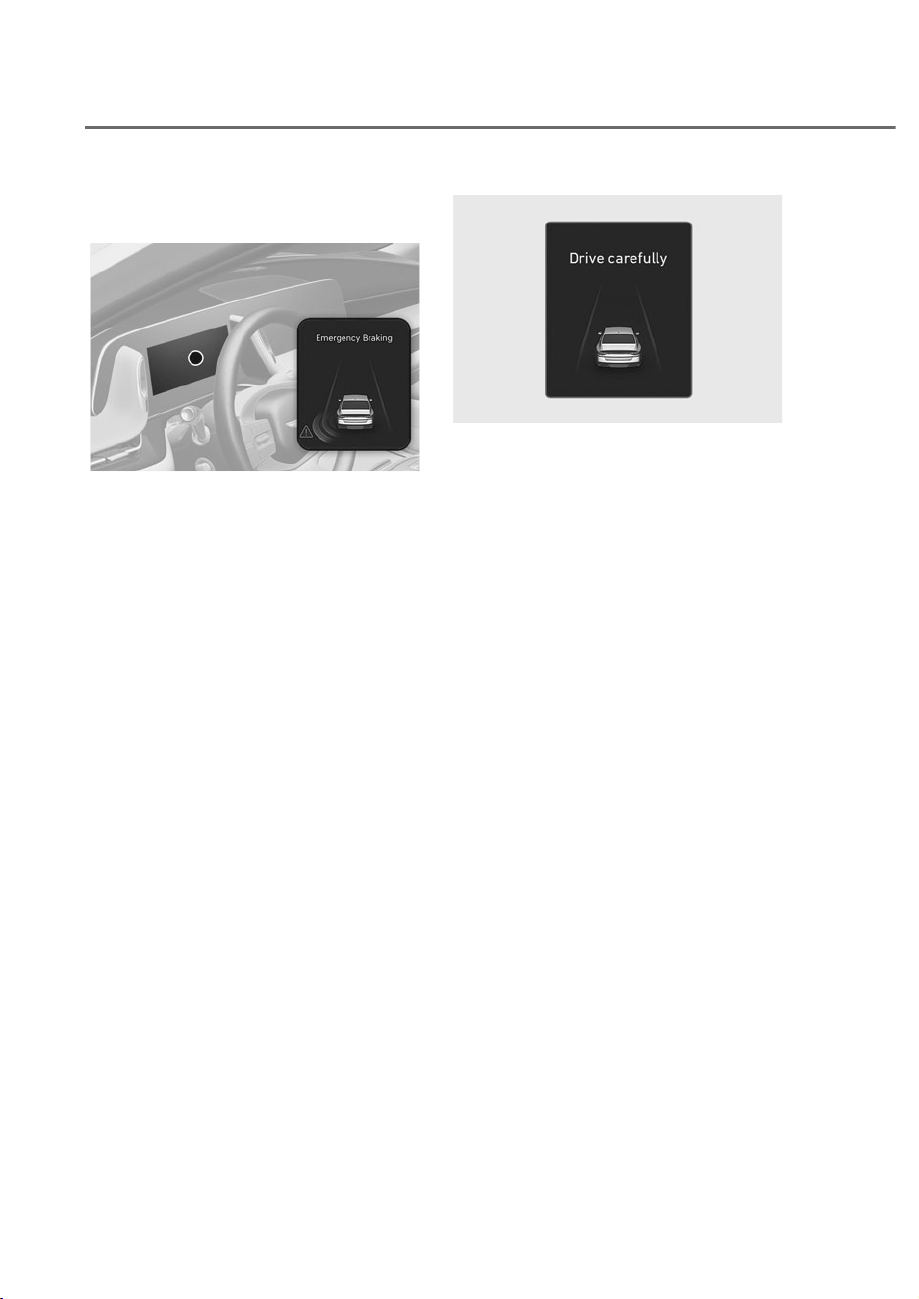
7-42
Driver Assistance System
Collision-avoidance assist (while
departing)
ORS071115L
ORS071115L
• To warn the driver of a collision, the
warning light on the side view mirror
will blink and a warning message will
appear on the instrument cluster. At
the same time, an audible warning
will sound, warning light on the head-
up display will blink and the steering
wheel will vibrate.
• Emergency braking will be assisted
to help prevent a collision with the
vehicle in the blind spot area.
• Collision-Avoidance Assist will operate
when your vehicle speed is below 2
mph (3 km/h) and the speed of the
vehicle in the blind spot area is above
3 mph (5 km/h).
ORS071102L
ORS071102L
• When the vehicle is stopped due
to emergency braking, the ‘Drive
carefully’ warning message will
appear on the instrument cluster.
For your safety, the driver should
depress the brake pedal immediately
and check the surroundings.
• Brake control will end after the vehicle
is stopped by emergency braking for
approximately 2 seconds.

7-43
07
WARNING
Take the following precautions when
XVLQJ%OLQG6SRW&ROOLVLRQ$YRLGDQFH
Assist:
• )RU\RXUVDIHW\RQO\FKDQJHWKH
6HWWLQJVDIWHUSDUNLQJWKHYHKLFOHDWD
VDIHORFDWLRQ
• ,IDQ\RWKHUV\VWHPȂVZDUQLQJ
PHVVDJHLVGLVSOD\HGRUDXGLEOH
ZDUQLQJLVJHQHUDWHG%OLQG6SRW
&ROOLVLRQ$YRLGDQFH$VVLVWȂVZDUQLQJ
PHVVDJHPD\QRWEHGLVSOD\HG
DQGDXGLEOHZDUQLQJPD\QRWEH
JHQHUDWHG
• <RXPD\QRWKHDUWKHZDUQLQJVRXQG
RI%OLQG6SRW&ROOLVLRQ$YRLGDQFH
$VVLVWLIWKHVXUURXQGLQJLVQRLV\
• %OLQG6SRW&ROOLVLRQ$YRLGDQFH
$VVLVWPD\QRWRSHUDWHLIWKHGULYHU
DSSOLHVWKHEUDNHSHGDOWRDYRLGD
FROOLVLRQ
• :KHQ%OLQG6SRW&ROOLVLRQ$YRLGDQFH
$VVLVWLVRSHUDWLQJEUDNLQJFRQWURO
E\WKHIXQFWLRQZLOODXWRPDWLFDOO\
FDQFHOZKHQWKHGULYHUH[FHVVLYHO\
depresses the accelerator pedal or
VKDUSO\VWHHUVWKHYHKLFOH
• During Blind-Spot Collision-
$YRLGDQFH$VVLVWRSHUDWLRQWKH
YHKLFOHPD\VWRSVXGGHQO\LQMXULQJ
passengers and shifting loose
REMHFWV$OZD\VKDYHWKHVHDWEHOWRQ
DQGNHHSORRVHREMHFWVVHFXUHG
• (YHQLIWKHUHLVDSUREOHPZLWK%OLQG
6SRW&ROOLVLRQ$YRLGDQFH$VVLVWWKH
YHKLFOHVEDVLFVWHHULQJDQGEUDNLQJ
ZLOOIXQFWLRQQRUPDOO\
• %OLQG6SRW&ROOLVLRQ$YRLGDQFH$VVLVW
does not operate in all situations and
FDQQRWDYRLGDOOFROOLVLRQV
• %OLQG6SRW&ROOLVLRQ$YRLGDQFH
$VVLVWPD\ZDUQWKHGULYHUODWHRU
PD\QRWZDUQWKHGULYHUGHSHQGLQJ
RQWKHURDGDQGGULYLQJFRQGLWLRQV
• 'ULYHUVKRXOGPDLQWDLQFRQWURORIWKH
YHKLFOHDWDOOWLPHV'RQRWGHSHQG
RQ%OLQG6SRW&ROOLVLRQ$YRLGDQFH
$VVLVW0DLQWDLQDVDIHEUDNLQJ
GLVWDQFHDQGLIQHFHVVDU\GHSUHVV
WKHEUDNHSHGDOWRUHGXFHGULYLQJ
VSHHGRUWRVWRSWKHYHKLFOH
• 1HYHURSHUDWH%OLQG6SRW&ROOLVLRQ
$YRLGDQFH$VVLVWRQSHRSOHDQLPDO
REMHFWVHWF,WPD\FDXVHVHULRXV
LQMXU\RUGHDWK
WARNING
7KHEUDNHFRQWUROPD\QRWRSHUDWH
SURSHUO\GHSHQGLQJRQWKHVWDWXVRI
(6&(OHFWURQLF6WDELOLW\&RQWURO
7KHUHZLOORQO\EHDZDUQLQJZKHQ
• 7KH(6&(OHFWURQLF6WDELOLW\&RQWURO
warning light is on
• (6&(OHFWURQLF6WDELOLW\&RQWUROLV
engaged in a different function
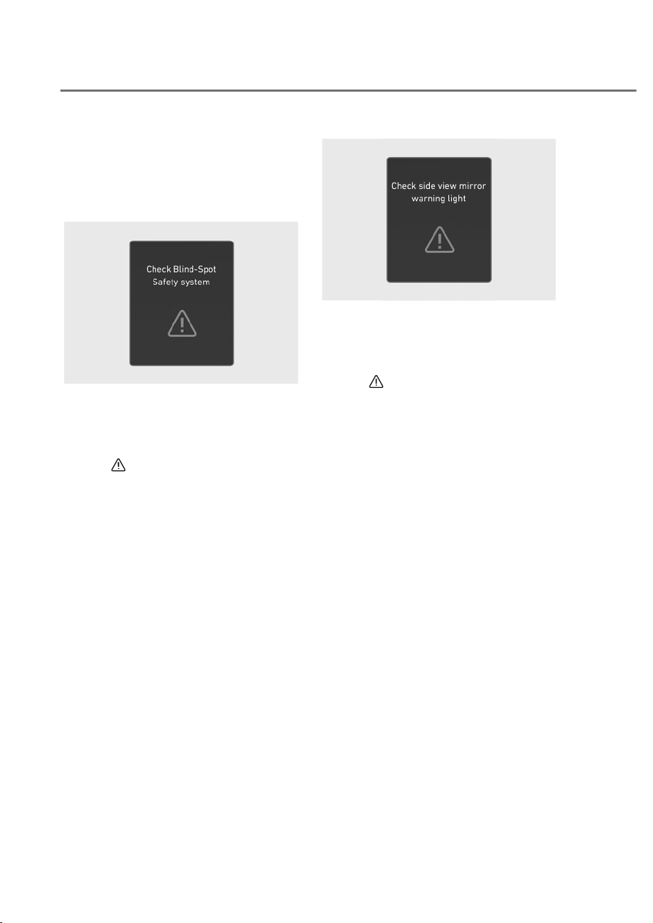
7-44
Driver Assistance System
%OLQG6SRW&ROOLVLRQ$YRLGDQFH
Assist malfunction and
limitations
Blind-Spot Collision-Avoidance
Assist malfunction
OJWEV071019L
OJWEV071019L
When Blind-Spot Collision-Avoidance
Assist is not working properly, the ‘Check
Blind-Spot Safety system’ warning
message will appear on the instrument
cluster for several seconds, and the
master (
) warning light will illuminate
on the instrument cluster. If this occurs,
have the vehicle inspected by an
authorized retailer of Genesis Branded
products.
OJWEV071021L
OJWEV071021L
When the side view mirror warning
light is not working properly, the ‘Check
side view mirror warning light’ warning
message will appear on the instrument
cluster for several seconds, and the
master (
) warning light will illuminate
on the instrument cluster. If this occurs,
have the vehicle inspected by an
authorized retailer of Genesis Branded
products.
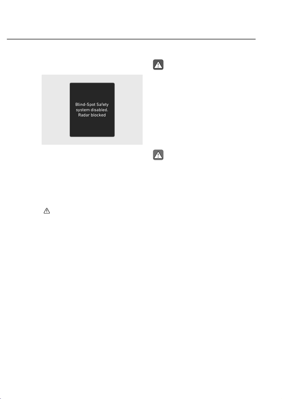
7-45
07
Blind-Spot Collision-Avoidance
Assist disabled
OTM070098N
OTM070098N
When the rear bumper around the rear
corner radar or sensor is covered with
foreign material, such as snow or rain,
or installing a trailer or carrier, it can
reduce the detecting performance and
temporarily limit or disable Blind-Spot
Collision-Avoidance Assist.
If this occurs, the ‘Blind-Spot Safety
system disabled. Radar blocked’ warning
message will appear, and the master
(
) warning light will illuminate on the
instrument cluster.
Blind-Spot Collision-Avoidance Assist
will operate properly when such foreign
material or trailer, etc., is removed, and
then the engine is restarted.
If Blind-Spot Collision-Avoidance Assist
does not operate properly after it is
removed, have the vehicle inspected by
an authorized retailer of Genesis Branded
products.
WARNING
• (YHQWKRXJKWKHZDUQLQJPHVVDJH
GRHVQRWDSSHDURQWKHFOXVWHU%OLQG
6SRW&ROOLVLRQ$YRLGDQFH$VVLVWPD\
QRWSURSHUO\RSHUDWH
• %OLQG6SRW&ROOLVLRQ$YRLGDQFH
$VVLVWPD\QRWSURSHUO\RSHUDWHLQ
DQDUHDIRUH[DPSOHRSHQWHUUDLQ
ZKHUHDQ\REMHFWVDUHQRWGHWHFWHG
ULJKWDIWHUWKHHQJLQHLVWXUQHGRQRU
ZKHQWKHGHWHFWLQJVHQVRULVEORFNHG
with foreign material right after the
HQJLQHLVWXUQHGRQ
CAUTION
7XUQRII%OLQG6SRW&ROOLVLRQ$YRLGDQFH
$VVLVWWRLQVWDOORUUHPRYHDWUDLOHU
FDUULHURUDQRWKHUDWWDFKPHQW7XUQRQ
%OLQG6SRW&ROOLVLRQ$YRLGDQFH$VVLVW
ZKHQILQLVKHG
Limitations of Blind-Spot Collision-
Avoidance Assist
Blind-Spot Collision-Avoidance Assist
may not operate properly, or it may
operate unexpectedly under the
following circumstances:
• There is inclement weather, such as
heavy snow, heavy rain, etc.
• The detecting sensor is covered with
snow, rain, dirt, etc.
• The temperature around the
detecting sensor is high or low due to
surrounding environment.
• The detecting sensor is blocked while
driving near a vehicle, pillar, or wall.
• Driving on a highway ramp or driving
through a tollgate.

7-46
Driver Assistance System
• The road pavement (or the peripheral
ground) abnormally contains metallic
components (for example, possibly
due to subway construction).
• There is a fixed object near the
vehicle, such as sound barriers,
guardrails, central dividers, entry
barriers, street lamps, signs,
tunnels, walls, etc. (including double
structures)
• Driving through a narrow road where
trees or grass are overgrown
• Driving in vast areas where there
are few vehicles or structures (for
example, desert, meadow, suburb,
etc.)
• Driving on a wet road surface, such as
a puddle on the road
• The other vehicle drives very close
behind your vehicle, or the other
vehicle passes by your vehicle in close
proximity
• The speed of the other vehicle is very
fast that it passes by your vehicle in a
short time
• Your vehicle passes by the other
vehicle
• Your vehicle changes lane
• Your vehicle has started at the same
time as the vehicle next to you and
has accelerated
• The vehicle in the next lane moves
two lanes away from you, or when the
vehicle two lanes away moves to the
next lane from you
• A trailer, carrier or other attachment is
installed around the rear corner radar
• The bumper around the rear corner
radar is covered with objects, such as
a bumper sticker, bumper guard, bike
rack, etc.
• The bumper around the rear corner
radar is impacted, damaged or the
radar is out of position
• Your vehicle height is low or high
due to heavy loads, abnormal tire
pressure, etc.
Blind-Spot Collision-Avoidance Assist
may not operate properly, or it may
operate unexpectedly when the
following objects are detected:
• A motorcycle or bicycle is detected
• A vehicle such as a flat trailer is
detected
• A big vehicle such as a bus or truck is
detected
• A moving obstacle such as a
pedestrian, animal, shopping cart or a
baby stroller is detected
• A vehicle with low height such as a
sports car is detected
Braking control may not work, driver’s
attention is required in the following
circumstances:
• The vehicle severely vibrates while
driving over a bumpy road, uneven
road or concrete patch
• Driving on a slippery surface due to
snow, water puddle, ice, etc.
• The tire pressure is low or a tire is
damaged
• The braking system has been modified
• The vehicle makes abrupt lane
changes
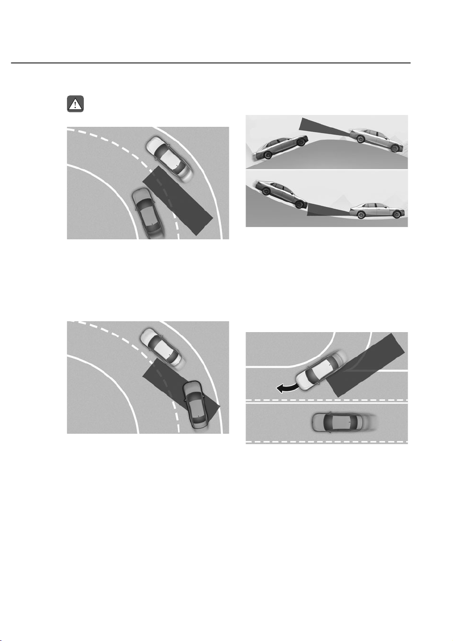
7-47
07
WARNING
• 'ULYLQJRQDFXUYHGURDG
ORS073074
ORS073074
%OLQG6SRW&ROOLVLRQ$YRLGDQFH
$VVLVWPD\QRWRSHUDWHSURSHUO\
ZKHQGULYLQJRQDFXUYHGURDG7KH
IXQFWLRQPD\QRWGHWHFWWKHYHKLFOH
LQWKHQH[WODQH
$OZD\VSD\DWWHQWLRQWRURDGDQG
GULYLQJFRQGLWLRQVZKLOHGULYLQJ
ORS071050
ORS071050
%OLQG6SRW&ROOLVLRQ$YRLGDQFH
$VVLVWPD\QRWRSHUDWHSURSHUO\
ZKHQGULYLQJRQDFXUYHGURDG7KH
IXQFWLRQPD\UHFRJQL]HDYHKLFOHLQ
WKHVDPHODQH
$OZD\VSD\DWWHQWLRQWRURDGDQG
GULYLQJFRQGLWLRQVZKLOHGULYLQJ
• 'ULYLQJRQDQLQFOLQHGURDG
ORS071048
ORS071048
%OLQG6SRW&ROOLVLRQ$YRLGDQFH
$VVLVWPD\QRWRSHUDWHSURSHUO\
ZKHQGULYLQJRQDVORSH7KH
IXQFWLRQPD\QRWGHWHFWWKHYHKLFOH
LQWKHQH[WODQHRUPD\LQFRUUHFWO\
GHWHFWWKHJURXQGRUVWUXFWXUH
$OZD\VSD\DWWHQWLRQWRURDGDQG
GULYLQJFRQGLWLRQVZKLOHGULYLQJ
• 'ULYLQJZKHUHWKHURDGLVPHUJLQJ
GLYLGLQJ
ORS071049
ORS071049
%OLQG6SRW&ROOLVLRQ$YRLGDQFH
$VVLVWPD\QRWRSHUDWHSURSHUO\
ZKHQGULYLQJZKHUHWKHURDGPHUJHV
RUGLYLGHV7KHIXQFWLRQPD\QRW
GHWHFWWKHYHKLFOHLQWKHQH[WODQH
$OZD\VSD\DWWHQWLRQWRURDGDQG
GULYLQJFRQGLWLRQVZKLOHGULYLQJ
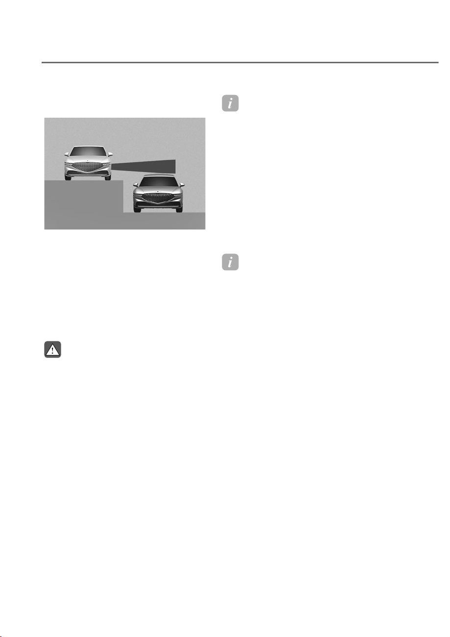
7-48
Driver Assistance System
• 'ULYLQJZKHUHWKHKHLJKWVRIWKH
lanes are different
ORS071051
ORS071051
%OLQG6SRW&ROOLVLRQ$YRLGDQFH
$VVLVWPD\QRWRSHUDWHSURSHUO\
ZKHQGULYLQJZKHUHWKHKHLJKWVRI
WKHODQHVDUHGLIIHUHQW7KHIXQFWLRQ
PD\QRWGHWHFWWKHYHKLFOHRQD
road with different lane heights
XQGHUSDVVMRLQLQJVHFWLRQJUDGH
VHSDUDWHGLQWHUVHFWLRQVHWF
$OZD\VSD\DWWHQWLRQWRURDGDQG
GULYLQJFRQGLWLRQVZKLOHGULYLQJ
WARNING
• :KHQ\RXDUHWRZLQJDWUDLOHURU
DQRWKHUYHKLFOHPDNHVXUHWKDW
\RXWXUQRII%OLQG6SRW&ROOLVLRQ
$YRLGDQFH$VVLVW
• %OLQG6SRW&ROOLVLRQ$YRLGDQFH
$VVLVWPD\QRWRSHUDWHSURSHUO\LI
LQWHUIHUHGE\VWURQJHOHFWURPDJQHWLF
ZDYHV
• %OLQG6SRW&ROOLVLRQ$YRLGDQFH$VVLVW
PD\QRWRSHUDWHIRUȸȼVHFRQGVDIWHU
WKHYHKLFOHLVVWDUWHGRUWKHUHDU
FRUQHUUDGDUVDUHLQLWLDOL]HG
Information
This device complies with Part 15 of the
F rules. peration is sub ect to the
following three conditions:
1. This device may not cause harmful
interference, and
2. This device must accept any
interference received, including
interference that may cause undesired
operation.
3. hanges or modifications not expressly
approved by the party responsible
for compliance could void the user’s
authority to operate the device.
Information
Radio frequency radiation exposure
information:
This equipment complies with F
radiation exposure limits set forth for an
uncontrolled environment.
This equipment should be installed and
operated with minimum distance of 8 in.
(20 cm) between the radiator (antenna)
and your body.
This transmitter must not be co-located or
operating in con unction with any other
antenna or transmitter.
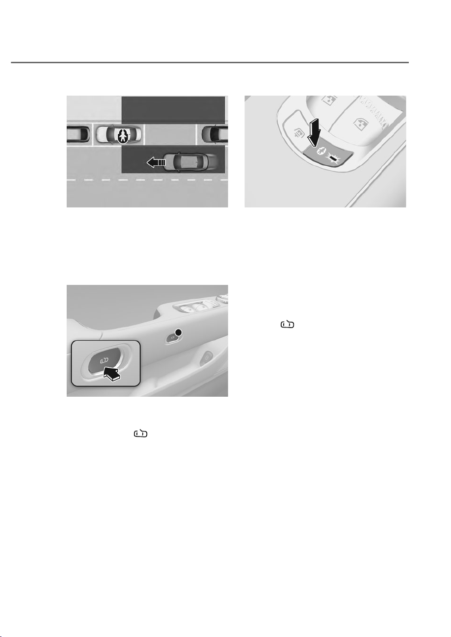
7-49
07
ORS071052
ORS071052
While your vehicle is stopped, and if Safe
Exit Assist detects a vehicle approaching
the rear corner of your vehicle and a
passenger opens a door, Safe Exit Assist
may warn you with a warning message
and a warning sound to help avoid a
collision.
ORS051021
ORS051021
If Safe Exit Assist detects a vehicle
approaching the rear corner of your
vehicle, the the doors will not open even
if the door open (
) button is pressed.
ORS051031
ORS051031
In addition, if an approaching vehicle
from the rear area is detected, Safe Exit
Assist prevents the doors from opening
in the following situation.
• The electronic child safety lock button
will not unlock even if the driver
presses the button.
• Regardless of whether the electronic
child safety lock button is in the lock
or unlock position, the doors will not
open for one time even if the door
open (
) button is pressed.
6$)((;,7$66,67ʚ6($ʛ
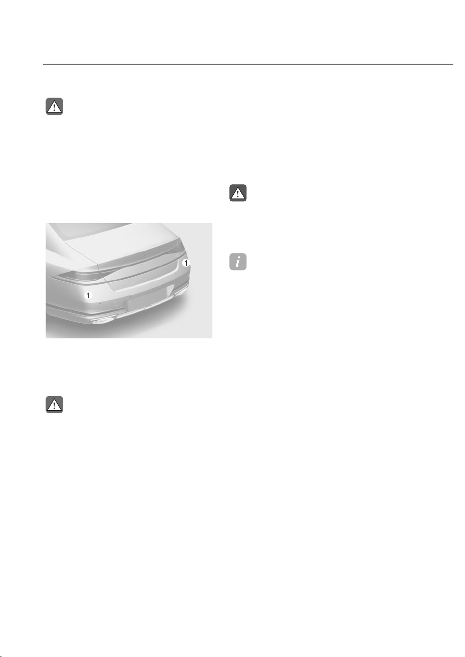
7-50
Driver Assistance System
CAUTION
:DUQLQJWLPLQJPD\YDU\GHSHQGLQJRQ
WKHVSHHGRIWKHDSSURDFKLQJYHKLFOH
'RQRWXVH6DIH([LW$VVLVWLQVWHDGRI
WKHHOHFWURQLFFKLOGVDIHW\ORFNEXWWRQ
7RSURWHFWUHDUVHDWSDVVHQJHUVXVHWKH
HOHFWURQLFFKLOGVDIHW\ORFNEXWWRQ
)RUPRUHGHWDLOVRQUHIHUWR(OHFWURQLF
&KLOG6DIHW\/RFNVHFWLRQLQFKDSWHUȼ
Detecting sensor
ORS072005N
ORS072005N
M: Rear corner radar
Refer to the picture above for the
detailed location of the detecting
sensors.
CAUTION
For more details on the precautions of
WKHUHDUFRUQHUUDGDUVUHIHUWRȃ%OLQG
6SRW&ROOLVLRQ$YRLGDQFH$VVLVW%&$Ȅ
VHFWLRQLQWKLVFKDSWHU
6DIH([LW$VVLVW6HWWLQJV
Safe Exit Assist
With the engine on, select ‘Driver
$VVLVWDQFHɌ'ULYLQJ6DIHW\Ɍ6DIH([LW
Assist’ from the Settings menu to turn on
Safe Exit Assist and deselect to turn off
the function.
WARNING
7KHGULYHUVKRXOGDOZD\VEHDZDUHRI
WKHVXUURXQGLQJV,Iȁ6DIH([LW$VVLVWȂ
LVGHVHOHFWHG6DIH([LW$VVLVWFDQQRW
DVVLVW\RX
Information
If the engine is restarted, Safe Exit Assist
will maintain the last setting.
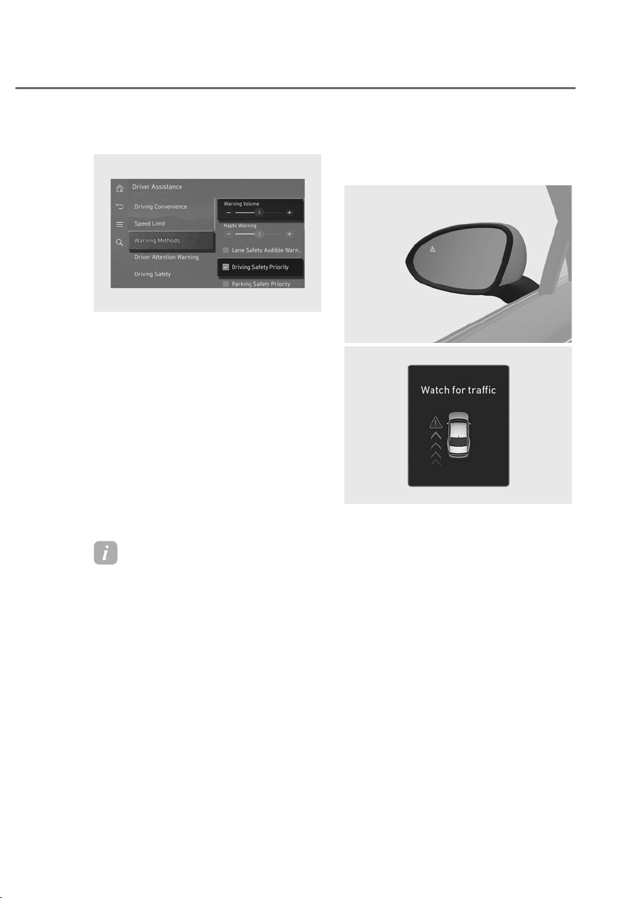
7-51
07
Warning methods
ORS073336N
ORS073336N
With the engine on, go to 'Driver
$VVLVWDQFHɌ:DUQLQJ0HWKRGVIURPWKH
Settings in the infotainment system to
select the following:
• Warning Volume: The warning volume
can be adjusted. If you turn off the
Warning Volume, for your safety, the
function may warn you with a low
volume.
• Haptic Warning: The steering wheel
vibration can be set.
• Driving Safety Priority: Your vehicle
lowers all other audio volumes when
the Driver Assistance system warning
sounds.
Information
• If you change the Warning Methods,
Warning Methods of other Driver
Assistance systems may change.
• Warning Method will maintain its last
setting even if the vehicle is restarted.
• The setting menu may not be available
for your vehicle depending on the
vehicle features and specifications.
6DIH([LW$VVLVW2SHUDWLRQ
Collision warning when exiting
vehicle
ORS071235
ORS071235
ORS071116L
ORS071116L
• When an approaching vehicle from
the rear is detected at the moment a
door is opened, the ‘Watch for traffic’
warning message will appear on the
instrument cluster, and an audible
warning will sound.
• Safe Exit Assist will warn the driver
when your vehicle speed is below 2
mph (3 km/h), and the speed of the
approaching vehicle from the rear is
above 4 mph (6 km/h).

7-52
Driver Assistance System
Safe Exit Assist linked with
Electronic child safety lock
ORS071217L
ORS071217L
• When Electric child safety lock is
operating and an approaching vehicle
from the rear area is detected, the
rear doors cannot be unlocked even
if the driver tries to unlock the rear
doors using the electronic child safety
lock button. The warning light on the
side view mirror will blink and 'Check
traffic in the blind spot, then try again'
warning message will appear on the
instrument cluster.
• Safe Exit Assist will warn the driver
when vehicle speed is below 2
mph (3 km/h) and the speed of the
approaching vehicle from the rear is
above 4 mph (6 km/h).
Information
• For more details on electric child safety
lock button, refer to “Electronic hild
Safety Lock” section in chapter 5.
• For more details on door open button,
refer to “Door pen” section in chapter
5.
CAUTION
• ,IWKHGULYHUSUHVVHVWKHHOHFWURQLF
FKLOGVDIHW\ORFNEXWWRQDJDLQ
ZLWKLQȸɁVHFRQGVDIWHUWKHZDUQLQJ
PHVVDJHDSSHDUV6DIH([LW$VVLVW
MXGJHVWKDWWKHGULYHUKDVXQORFNHG
the doors acknowledging the rear
VWDWXV7KHHOHFWURQLFFKLOGVDIHW\
ORFNZLOOWXUQRIIEXWWRQLQGLFDWRU
2))DQGWKHUHDUGRRUVZLOOXQORFN
$OZD\VFKHFNWKHVXUURXQGLQJV
EHIRUHWXUQLQJRIIWKHHOHFWURQLF
FKLOGVDIHW\ORFNEXWWRQ
• ,IWKHGULYHUSUHVVHVWKHGRRU
open (
EXWWRQDJDLQZLWKLQȸɁ
seconds after the warning message
DSSHDUV6DIH([LW$VVLVWMXGJHVWKDW
WKHGULYHUKDVSUHVVHGWKHEXWWRQ
DFNQRZOHGJLQJWKHUHDUVWDWXV7KH
GRRUVZLOORSHQZKHWKHUDYHKLFOH
LVDSSURDFKLQJ$OZD\VFKHFNWKH
VXUURXQGLQJVEHIRUHSUHVVLQJWKH
door open (
EXWWRQ
Information
If a rear door is opened from the outside,
it will open regardless of Safe Exit Assist
operation.
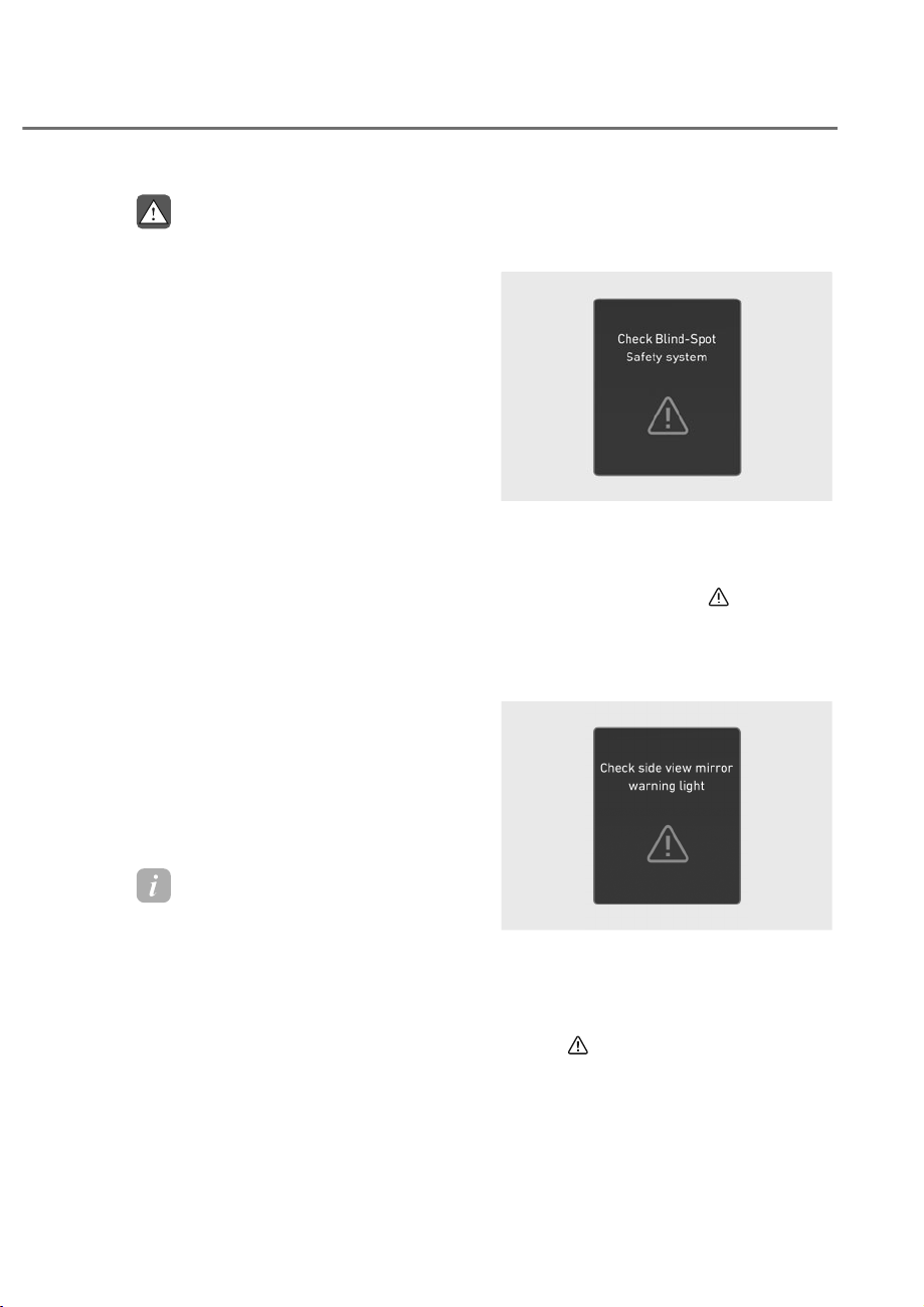
7-53
07
WARNING
Take the following precautions when
XVLQJ6DIH([LW$VVLVW
• )RU\RXUVDIHW\RQO\FKDQJHWKH
6HWWLQJVDIWHUSDUNLQJWKHYHKLFOHDWD
VDIHORFDWLRQ
• ,IDQ\RWKHUV\VWHPȂVZDUQLQJ
PHVVDJHLVGLVSOD\HGRUDXGLEOH
ZDUQLQJLVJHQHUDWHG6DIH([LW
$VVLVWZDUQLQJPHVVDJHPD\QRWEH
GLVSOD\HGDQGDXGLEOHZDUQLQJPD\
QRWEHJHQHUDWHG
• <RXPD\QRWKHDUWKHZDUQLQJVRXQG
RI6DIH([LW$VVLVWLIWKHVXUURXQGLQJV
DUHQRLV\
• 6DIH([LW$VVLVWGRHVQRWRSHUDWHLQ
DOOVLWXDWLRQVDQGFDQQRWSUHYHQWDOO
FROOLVLRQV
• 6DIH([LW$VVLVWPD\ZDUQWKHGULYHU
ODWHRUPD\QRWZDUQWKHGULYHU
GHSHQGLQJRQWKHURDGDQGGULYLQJ
FRQGLWLRQV$OZD\VFKHFNYHKLFOH
VXUURXQGLQJV
• 7KHGULYHUDQGSDVVHQJHUVDUH
UHVSRQVLEOHIRUDFFLGHQWVWKDWRFFXU
ZKLOHH[LWLQJWKHYHKLFOH$OZD\V
FKHFNWKHVXUURXQGLQJVEHIRUH\RX
H[LWWKHYHKLFOH
• 1HYHUGHOLEHUDWHO\RSHUDWH6DIH([LW
$VVLVW'RLQJVRPD\OHDGWRVHULRXV
LQMXU\RUGHDWK
Information
• After the engine is turned off, Safe Exit
Assist operates approximately for 3
minutes, but turns off immediately if
the doors are locked.
• The images and colors in the
instrument cluster may differ
depending on the cluster type or theme
selected from the settings menu.
6DIH([LW$VVLVWPDOIXQFWLRQDQG
Limitations
Safe Exit Assist malfunction
OJWEV071019L
OJWEV071019L
When Safe Exit Assist is not working
properly, the ‘Check Blind-Spot Safety
system’ warning message will appear
on the instrument cluster for several
seconds, and the master (
) warning
light will illuminate on the instrument
cluster. If this occurs, have the vehicle
inspected by an authorized retailer of
Genesis Branded products.
OJWEV071021L
OJWEV071021L
When the side view mirror warning
light is not working properly, the ‘Check
side view mirror warning light’ warning
message will appear on the instrument
cluster for several seconds, and the
master (
) warning light will illuminate
on the instrument cluster. If this occurs,
have the vehicle inspected by an
authorized retailer of Genesis Branded
products.

7-54
Driver Assistance System
Safe Exit Assist disabled
OTM070098N
OTM070098N
When the rear bumper around the rear
corner radar or sensor is covered with
foreign material, such as snow or rain,
or installing a trailer or carrier, it can
reduce the detecting performance and
temporarily limit or disable Safe Exit
Assist.
If this occurs, the ‘Blind-Spot Safety
system disabled. Radar blocked’ warning
message will appear on the instrument
cluster.
Safe Exit Assist will operate properly
when such foreign material or trailer,
etc., is removed, and then the engine is
restarted.
If Safe Exit Assist does not operate
properly after it is removed, have the
vehicle inspected by an authorized
retailer of Genesis Branded products.
WARNING
• (YHQWKRXJKWKHZDUQLQJPHVVDJH
GRHVQRWDSSHDURQWKHFOXVWHU6DIH
([LW$VVLVWPD\QRWSURSHUO\RSHUDWH
• 6DIH([LW$VVLVWPD\QRWSURSHUO\
RSHUDWHLQDQDUHDIRUH[DPSOH
RSHQWHUUDLQZKHUHDQ\REMHFWVDUH
not detected right after the engine
LVWXUQHGRQRUZKHQWKHGHWHFWLQJ
VHQVRULVEORFNHGZLWKIRUHLJQ
material right after the engine is
WXUQHGRQ
CAUTION
7XUQRII6DIH([LW$VVLVWWRLQVWDOORU
UHPRYHDWUDLOHUFDUULHURUDQRWKHU
DWWDFKPHQW7XUQRQ6DIH([LW$VVLVW
ZKHQILQLVKHG
Limitations of Safe Exit Assist
Safe Exit Assist may not operate properly,
or it may operate unexpectedly under the
following circumstances:
• Getting out of the vehicle where trees
or grass are overgrown
• Getting out of the vehicle where the
road is wet
• The approaching vehicle is very fast or
very slow

7-55
07
Information
For more details on the limitations of the
rear corner radar, refer to “Blind-Spot
ollision-Avoidance Assist (B A)” section
in this chapter.
WARNING
• 6DIH([LW$VVLVWPD\QRWRSHUDWH
SURSHUO\LILQWHUIHUHGE\VWURQJ
HOHFWURPDJQHWLFZDYHV
• 6DIH([LW$VVLVWPD\QRWRSHUDWH
IRUȺVHFRQGVDIWHUWKHYHKLFOHLV
VWDUWHGRUWKHUHDUFRUQHUUDGDUVDUH
LQLWLDOL]HG
• ,IWKHYHKLFOHLVWXUQHGRIIDQG
UHVWDUWHGZKLOHWKHUDGDULVEORFNHG
RUPDOIXQFWLRQHGWKHFRQGLWLRQLV
PDLQWDLQHG7KHUHIRUH6DIH([LW
$VVLVWPD\QRWRSHUDWHSURSHUO\
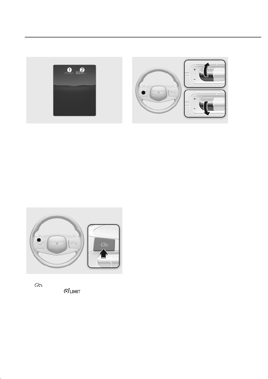
7-56
Driver Assistance System
ORS072261N
ORS072261N
M Speed Limit indicator
N Set speed
You can set the speed limit when you do
not want to drive over a specific speed.
If you drive over the preset speed limit,
Manual Speed Limit Assist operates
(set speed limit will blink and chime will
sound) until the vehicle speed returns
within the speed limit.
0DQXDO6SHHG/LPLW$VVLVW
Operation
Setting speed limit
ORS071025
ORS071025
1. Press and hold Driving Assist
(
) button at the desired speed. The
Speed Limit (
) indicator will
illuminate on the cluster.
ORS071026L
ORS071026L
2. Push the + switch up or - switch down,
and release it at the desired speed.
Push the + switch up or - switch down
and hold it. The speed will increase
or decrease to the nearest multiple of
five (multiple of ten in km/h) at first,
and then increase or decrease by 5
mph (10 km/h).
0$18$/63(('/,0,7$66,67ʚ06/$ʛ
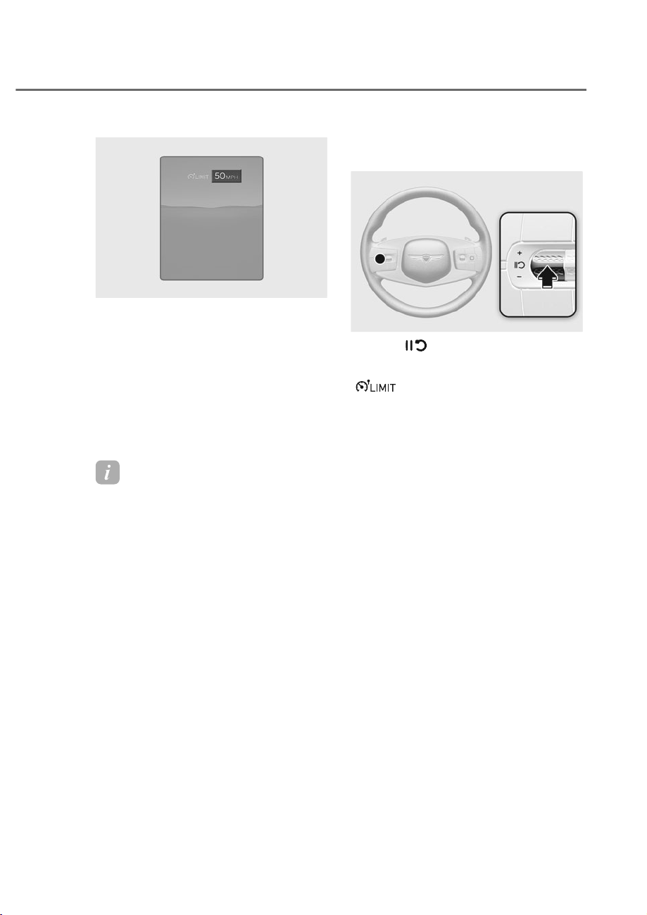
7-57
07
ORS072262N
ORS072262N
3. The set speed limit will be displayed
on the cluster.
If you would like to drive over the
preset speed limit, depress the
accelerator pedal beyond the pressure
point to activate the kickdown
mechanism.
The set speed limit will blink and
chime will sound until you return the
vehicle speed within the speed limit.
Information
• When the accelerator pedal is not
depressed beyond the pressure point,
vehicle speed will maintain within the
speed limit.
• A clicking sound may be heard from
the kickdown mechanism when the
accelerator pedal is depressed beyond
the pressure point.
Temporarily pausing Manual Speed
Limit Assist
ORS071027
ORS071027
Press the switch to temporarily
pause the set speed limit. The set speed
limit will turn off but the Speed Limit
(
) indicator will stay on.
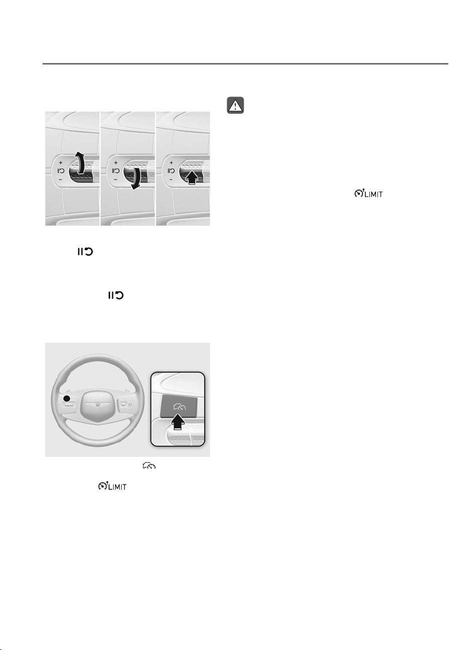
7-58
Driver Assistance System
Resuming Manual Speed Limit Assist
ORS071184
ORS071184
To resume Manual Speed Limit Assist
after the function was paused, operate
the +, -,
switch.
If you push the + switch up or – switch
down, vehicle speed will be set to the
current speed on the cluster.
If you press the
switch, vehicle
speed will resume to the preset speed.
Turning off Manual Speed Limit
Assist
ORS071025
ORS071025
Press the Driving Assist ( ) button to
turn Manual Speed Limit Assist off. The
Speed Limit (
) indicator will go
off.
WARNING
Take the following precautions when
XVLQJ0DQXDO6SHHG/LPLW$VVLVW
• $OZD\VVHWWKHYHKLFOHVSHHGXQGHU
WKHVSHHGOLPLWLQ\RXUDUHD
• .HHS0DQXDO6SHHG/LPLW$VVLVWRII
ZKHQWKHIXQFWLRQLVQRWLQXVHWR
DYRLGLQDGYHUWHQWO\VHWWLQJDVSHHG
Check that the Speed Limit (
LQGLFDWRULVRII
• 0DQXDO6SHHG/LPLW$VVLVWGRHV
QRWVXEVWLWXWHIRUSURSHUDQGVDIH
GULYLQJ,WLVWKHUHVSRQVLELOLW\RIWKH
GULYHUWRDOZD\VGULYHVDIHO\DQGEH
DZDUHRIXQH[SHFWHGDQGVXGGHQ
VLWXDWLRQV3D\DWWHQWLRQWRWKHURDG
FRQGLWLRQVDWDOOWLPHV
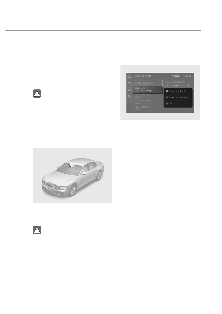
7-59
07
Intelligent Speed Limit Assist uses
information from the detected road sign
and navigation system to inform the
driver of the speed limit and additional
information of the current road. Also,
Intelligent Speed Limit Assist helps the
driver to maintain within the speed limit
of the road.
CAUTION
• ,QWHOOLJHQW6SHHG/LPLW$VVLVWPD\
QRWRSHUDWHSURSHUO\LIWKHIXQFWLRQLV
XVHGLQRWKHUFRXQWULHV
• ,IDQDYLJDWLRQLVDSSOLHGWR\RXU
YHKLFOHWKHQDYLJDWLRQQHHGVWREH
UHJXODUO\XSGDWHGIRU,QWHOOLJHQW
Speed Limit Assist to operate
SURSHUO\
Detecting sensor
ORS071001
ORS071001
M: Front view camera
Refer to the picture above for the
detailed location of the detecting sensor.
CAUTION
For more details on the precautions
RIWKHIURQWYLHZFDPHUDUHIHUWR
ȃ)RUZDUG&ROOLVLRQ$YRLGDQFH$VVLVW
)&$ȄVHFWLRQLQWKLVFKDSWHU
Intelligent Speed Limit Assist
Settings
Speed Limit
ORS071227L
ORS071227L
With the engine on, select or deselect
ȁ'ULYHU$VVLVWDQFHɌ6SHHG/LPLWȂIURP
the Settings menu to set whether to use
each function.
• If ‘Speed Limit Assist’ is selected,
Intelligent Speed Limit Assist will
inform the driver of speed limit and
additional road signs. In addition,
Intelligent Speed Limit Assist will
inform the driver to change set speed
of Manual Speed Limit Assist and/or
Smart Cruise Control to help the driver
stay within the speed limit.
• If ‘Speed Limit Warning’ is selected,
Intelligent Speed Limit Assist will
inform the driver of speed limit and
additional road signs. In addition,
Intelligent Speed Limit Assist will warn
the driver when the vehicle is driven
faster than the speed limit.
• If ‘Off’ is selected, Intelligent Speed
Limit Assist will turn off.
,17(//,*(1763(('/,0,7$66,67ʚ,6/$ʛʚ,)(48,33('ʛ
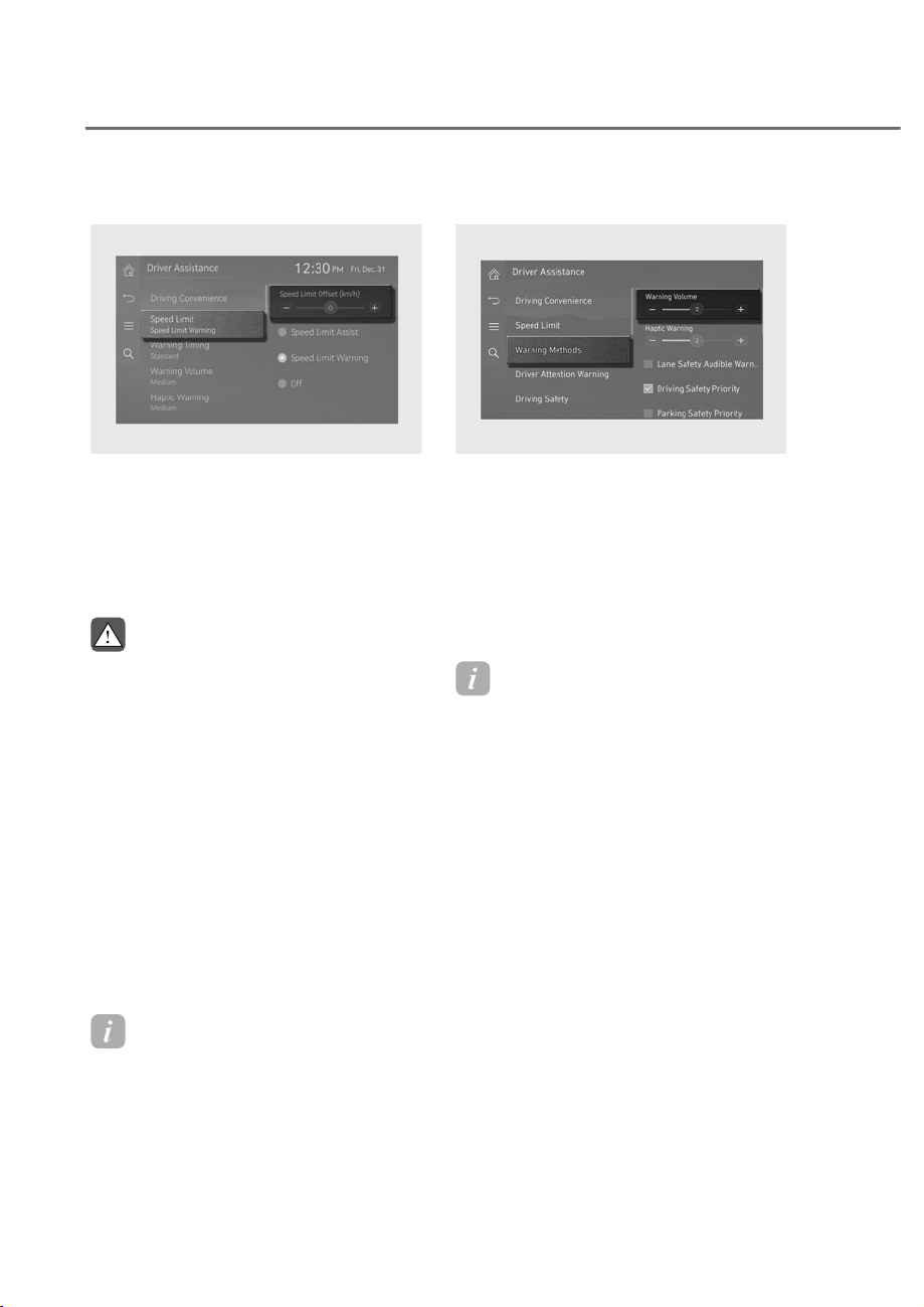
7-60
Driver Assistance System
Speed Limit Offset
ORS071263L
ORS071263L
With the engine on, when ‘Driver
$VVLVWDQFHɌ6SHHG/LPLWɌ6SHHG/LPLW
Offset’ is selected, the Speed Limit Offset
can be changed. Speed Limit Warning
and Speed Limit Assist will operate by
applying the Speed Limit Offset setting
to the detected speed limit.
WARNING
• )RU\RXUVDIHW\RQO\FKDQJHWKH
6HWWLQJVDIWHUSDUNLQJWKHYHKLFOHDWD
VDIHORFDWLRQ
• Speed Limit Assist function operates
EDVHGRQWKH2IIVHWVHWWLQJDGGHG
WRWKHVSHHGOLPLW,I\RXZDQWWR
change the set speed according to
WKHVSHHGOLPLWDGMXVWWKHRIIVHWWR
ȁɁȂ
• Speed Limit Warning function warns
WKHGULYHUZKHQGULYLQJVSHHG
H[FHHGVWKHVSHHGDWZKLFKWKHVHW
2IIVHWLVDGGHGWRVSHHGOLPLW,I\RX
want Speed Limit Warning to warn
\RXLPPHGLDWHO\ZKHQWKHGULYLQJ
VSHHGH[FHHGVWKHVSHHGOLPLW
DGMXVWWKHRIIVHWWRȁɁȂ
Information
The setting of 'Speed ffset' is not
reflected in Navigation-based Smart
ruise ontrol (NS ).
Warning methods
ORS073337N
ORS073337N
With the engine on, go to 'Driver
$VVLVWDQFHɌ:DUQLQJ0HWKRGVIURPWKH
Settings in the infotainment system to
select the following:
• Warning Volume: The warning volume
can be adjusted. If you turn off the
Warning Volume, for your safety, the
function may warn you with a low
volume.
Information
• If you change the Warning Methods,
Warning Methods of other Driver
Assistance systems may change.
• Warning Method will maintain its last
setting even if the vehicle is restarted.
• The setting menu may not be available
for your vehicle depending on the
vehicle features and specifications.

7-61
07
Intelligent Speed Limit Assist
Operation
Intelligent Speed Limit Assist will warn
and control the vehicle by ‘Displaying
speed limit’, ‘Warning overspeed’ and
‘Changing set speed’.
Information
Intelligent Speed Limit Assist warning and
control are described based on the ffset
ad ust to '0'. For details on ffset setting,
refer to the “Intelligent Speed Limit Assist
Settings”.
Displaying speed limit
ORS072090N
ORS072090N
Speed limit information is displayed on
the instrument cluster.
Information
• If speed limit information of the road
cannot be recognized, '---' sign will be
displayed. Refer to "Limitations of
Intelligent Speed Limit Assist" if the
road signs are difficult to recognize.
• Intelligent Speed Limit Assist provides
additional road sign information in
addition to speed limit. The additional
road sign information provided may
vary according to your country.
• The images and colors in the
instrument cluster may differ
depending on the cluster type or theme
selected from the settings menu.
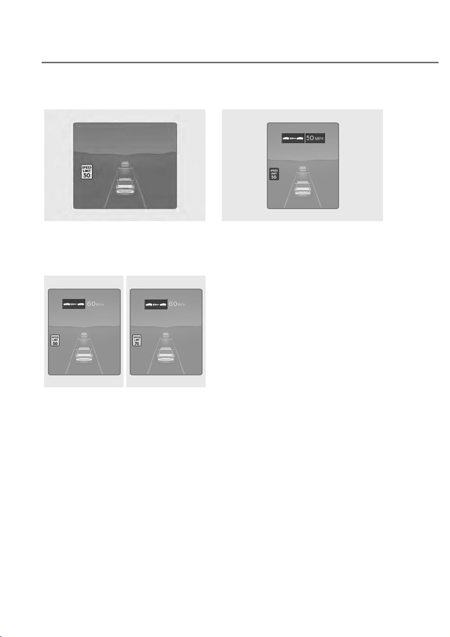
7-62
Driver Assistance System
Warning overspeed
ORS072091N
ORS072091N
When driving at a speed higher than the
displayed speed limit, the speed limit is
displayed in red.
Changing set speed
ORS072151N
ORS072151N
ORS072152N
ORS072152N
If the speed limit of the road changes
during the operation of Manual Speed
Limit Assist or Smart Cruise Control, an
arrow in the direction of up or down is
displayed to inform the driver that the set
speed needs to be changed. At this time,
the driver can change the set speed
according to the speed limit by using the
+ or – switch on the steering wheel.
Set Speed Auto Change
ORS073153N
ORS073153N
Manual Speed Limit Assist or Smart
Cruise Control assists the vehicle to
adjust its speed according to the speed
limit. When the cruising speed is set
as same as the speed limit, the vehicle
automatically adjusts its speed if the
speed limit changes.
The function operates on the road which
has a speed limit of 45 mph (70 km/h) or
higher. When the function is active, the
cruising speed on the instrument cluster
appears in green.
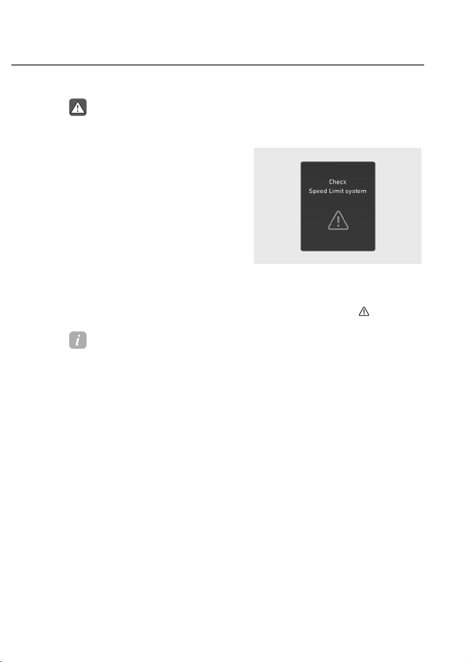
7-63
07
WARNING
• ,I\RXZDQWWRGULYHEHORZWKHVSHHG
OLPLWDGMXVWWKH2IIVHWXQGHUɁRU
use the – switch on the steering
ZKHHOWRORZHUWKHVHWVSHHG
• (YHQDIWHUFKDQJLQJWKHVHWVSHHG
according to the speed limit of the
URDGWKHYHKLFOHFDQVWLOOEHGULYHQ
RYHUWKHVSHHGOLPLW,IQHFHVVDU\
GHSUHVVWKHEUDNHSHGDOWRUHGXFH
\RXUGULYLQJVSHHG
• If the speed limit of the road is under
ȹɁPSKȺɁNPKWKHVHWVSHHG
FKDQJHIXQFWLRQZLOOQRWZRUN
• Intelligent Speed Limit Assist
operates using the speed unit in the
LQVWUXPHQWFOXVWHUVHWE\WKHGULYHU
If the speed unit is set to a unit other
WKDQWKHVSHHGXQLWXVHGLQ\RXU
DUHD,QWHOOLJHQW6SHHG/LPLW$VVLVW
PD\QRWRSHUDWHSURSHUO\
Information
• For more details on Manual Speed
Limit Assist operation, refer to
“Manual Speed Limit Assist (MSLA)”
section in this chapter.
• For more details on Smart ruise
ontrol operation, refer to “Smart
ruise ontrol (S )” section in this
chapter.
Intelligent Speed Limit Assist
0DOIXQFWLRQDQG/LPLWDWLRQV
Intelligent Speed Limit Assist
malfunction
OJWEV071025L
OJWEV071025L
When Intelligent Speed Limit Assist is not
working properly, the ‘Check Speed Limit
system’ warning message will appear
on the instrument cluster for several
seconds, and the master (
) warning
light will illuminate on the instrument
cluster. If this occurs, have the vehicle
inspected by an authorized retailer of
Genesis Branded products.

7-64
Driver Assistance System
Intelligent Speed Limit Assist
disabled
ORS071271L
ORS071271L
When the front windshield where the
front view camera is located is covered
with foreign material, such as snow
or rain, it can reduce the detecting
performance and temporarily limit or
disable Intelligent Speed Limit Assist.
If this occurs, the ‘Speed Limit system
disabled. Camera obscured’ warning
message will appear on the instrument
cluster.
Intelligent Speed Limit Assist will operate
properly when snow, rain or foreign
material is removed.
If Intelligent Speed Limit Assist does not
operate properly after it is removed, have
the vehicle inspected by an authorized
retailer of Genesis Branded products.
WARNING
• If the detecting sensor is
FRQWDPLQDWHGLPPHGLDWHO\DIWHU
VWDUWLQJWKHYHKLFOH,QWHOOLJHQW
6SHHG/LPLW$VVLVWPD\QRWRSHUDWH
SURSHUO\
• ,IWKHYHKLFOHLVWXUQHGRIIDQG
restarted while the camera is
REVFXUHGRUPDOIXQFWLRQHGWKH
FRQGLWLRQLVPDLQWDLQHG7KHUHIRUH
,QWHOOLJHQW6SHHG/LPLW$VVLVWPD\
QRWRSHUDWHSURSHUO\
Limitations of Intelligent Speed
Limit Assist
Intelligent Speed Limit Assist may not
operate properly, or it may operate
unexpectedly under the following
circumstances:
• The road sign is contaminated or
indistinguishable
- The road sign is difficult to see due
to bad weather, such as rain, snow,
fog, etc.
- The road sign is not clear or
damaged
- The road sign is partially obscured
by surrounding objects or shadow
• The road signs do not conform to the
standard
- The text or picture on the road sign
is different from the standard
- The road sign is installed between
the main line and the exit road or
between diverging roads
- There is no conditional road signs
on the road sign located on the exit
road
- A sign is attached to another vehicle
• The distance between the vehicle and
the road signs is too far
• The vehicle encounters illuminant
road signs
• Intelligent Speed Limit Assist
incorrectly recognizes numbers or
pictures in the street signs or other
signs as the speed limit
• A road sign near the road you are
driving is detected
• Multiple signs are installed close
together
• The minimum speed limit sign is
misrecognized

7-65
07
• The minimum speed limit sign is on
the road
• The brightness changes suddenly, for
example when entering or exiting a
tunnel or passing under a bridge
• Headlamps are not used or the
brightness of the headlamps are weak
at night or in the tunnel
• Road signs are difficult to recognize
due to the reflection of sunlight, street
lights, or oncoming vehicles
• The navigation information or GPS
information contain errors.
• The driver does not follow the guide
of the navigation.
• The driver is driving a new road that is
not in the navigation system yet.
• The field of view of the front view
camera is obstructed by sun glare
• Driving on a road that is sharply
curved or continuously curved
• Driving through speed bumps, or
driving up and down or left to right on
steep inclines
• The vehicle is shaking heavily
• Driving on a newly opened road
WARNING
• Intelligent Speed Limit Assist is a
supplemental function that helps the
GULYHUFRPSO\ZLWKWKHVSHHGOLPLW
RQWKHURDGDQGPD\QRWGLVSOD\WKH
correct speed limit or control the
GULYLQJVSHHGSURSHUO\
• $OZD\VVHWWKHYHKLFOHVSHHGWRWKH
VSHHGOLPLWLQ\RXUDUHD
• ,QWHOOLJHQW6SHHG/LPLW$VVLVWPD\
QRWRSHUDWHIRUȸȼVHFRQGVDIWHUWKH
YHKLFOHLVVWDUWHGRUWKHIURQWYLHZ
FDPHUDLVLQLWLDOL]HG
Information
For more details on the limitations of the
front view camera, refer to “Forward
ollision-Avoidance Assist (F A)” section
in this chapter.
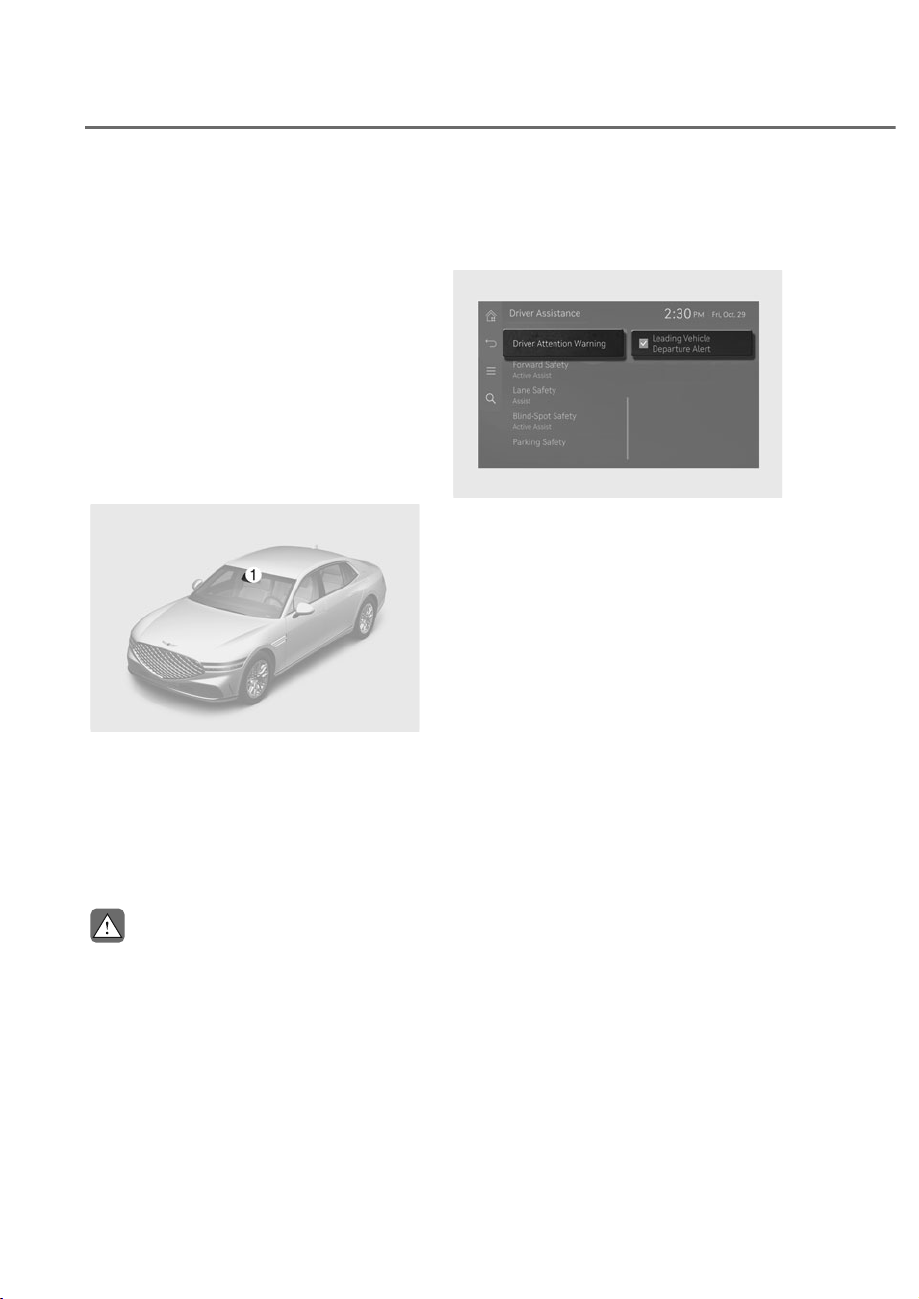
7-66
Driver Assistance System
'ULYHU$WWHQWLRQ:DUQLQJ
Driver Attention Warning helps monitor
your driving pattern while driving. When
the driver's attention level is below a
certain level, Driver Attention Warning
recommends a break to help with safe
driving.
/HDGLQJYHKLFOHGHSDUWXUHDOHUW
function
Leading Vehicle Departure Alert function
will inform the driver when a detected
vehicle in front departs.
Detecting sensor
ORS071001
ORS071001
M: Front view camera
The front view camera is used as a
detecting sensor to help detect driving
patterns and front vehicle departure
while vehicle is being driven.
Refer to the picture above for the
detailed location of the detecting sensor.
CAUTION
• $OZD\VNHHSWKHIURQWYLHZFDPHUDLQ
good condition to maintain optimal
SHUIRUPDQFHRI'ULYHU$WWHQWLRQ
:DUQLQJ
• For more details on the precautions
RIWKHIURQWYLHZFDPHUDUHIHUWR
ȃ)RUZDUG&ROOLVLRQ$YRLGDQFH$VVLVW
)&$ȄVHFWLRQLQWKLVFKDSWHU
'ULYHU$WWHQWLRQ:DUQLQJ
Settings
Leading Vehicle Departure Alert
ORS072232N
ORS072232N
With the engine on, select or deselect
ȁ'ULYHU$VVLVWDQFHɌ'ULYHU$WWHQWLRQ
Warning’ from the Settings menu to set
whether to use each function.
• If ‘Leading Vehicle Departure Alert’ is
selected, the function will inform the
driver when a detected vehicle in front
departs from a stop.
'5,9(5$77(17,21:$51,1*ʚ'$:ʛ
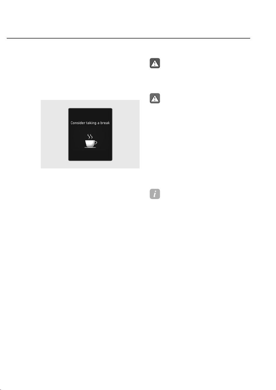
7-67
07
'ULYHU$WWHQWLRQ:DUQLQJ
Operation
Driver Attention Warning
The basic function of Driver Attention
Warning is to warn the driver ‘Consider
taking a break’.
OTM070105L
OTM070105L
• The ‘Consider taking a break’ message
will appear on the instrument cluster
and an audible warning will sound to
suggest that the driver take a break,
when the driver’s attention level is
below a certain level.
• Driver Attention Warning will not
suggest a break when the total driving
time is shorter than 4 minutes or 4
minutes has not passed after the last
break was suggested.
• A break is suggested when
your vehicle speed is between
approximately 0-120 mph (0-200
km/h).
WARNING
)RU\RXUVDIHW\RQO\FKDQJHWKH
6HWWLQJVDIWHUSDUNLQJWKHYHKLFOHDWD
VDIHORFDWLRQ
CAUTION
• 'ULYHU$WWHQWLRQ:DUQLQJPD\
VXJJHVWDEUHDNGHSHQGLQJRQWKH
GULYHUȂVGULYLQJSDWWHUQRUKDELWV
HYHQLIWKHGULYHUGRHVQȂWIHHO
IDWLJXHG
• 'ULYHU$WWHQWLRQ:DUQLQJLVD
VXSSOHPHQWDOIXQFWLRQDQGPD\QRW
EHDEOHWRGHWHUPLQHZKHWKHUWKH
GULYHULVLQDWWHQWLYH
• $GULYHUZKRIHHOVIDWLJXHGVKRXOG
WDNHDEUHDNDWDVDIHORFDWLRQHYHQ
WKRXJKWKHUHLVQREUHDNVXJJHVWLRQ
E\'ULYHU$WWHQWLRQ:DUQLQJ
Information
For more details on instrument cluster
settings, refer to “L D display control”
section in chapter 4.
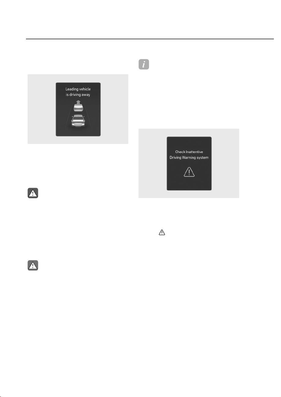
7-68
Driver Assistance System
Leading vehicle departure alert
function
ORS071199L
ORS071199L
When a detected vehicle in front departs
from a stop, Leading Vehicle Departure
Alert will inform the driver by displaying
the ‘Leading vehicle is driving away’
message on the instrument cluster and
an audible warning will sound.
WARNING
• ,IDQ\RWKHUV\VWHPȂVZDUQLQJ
PHVVDJHLVGLVSOD\HGRUDXGLEOH
ZDUQLQJLVJHQHUDWHG/HDGLQJ
9HKLFOH'HSDUWXUH$OHUWVZDUQLQJ
PHVVDJHPD\QRWEHGLVSOD\HG
DQGDXGLEOHZDUQLQJPD\QRWEH
JHQHUDWHG
• 7KHGULYHUKDVWKHUHVSRQVLELOLW\WR
VDIHO\GULYHDQGFRQWUROWKHYHKLFOH
CAUTION
• /HDGLQJ9HKLFOH'HSDUWXUH$OHUWLVD
VXSSOHPHQWDOIXQFWLRQDQGPD\QRW
DOHUWWKHGULYHUZKHQHYHUWKHIURQW
YHKLFOHGHSDUWVIURPDVWRS
• $OZD\VFKHFNWKHIURQWRIWKH
YHKLFOHDQGURDGFRQGLWLRQVEHIRUH
GHSDUWXUH
Information
The images and colors in the instrument
cluster may differ depending on the cluster
type or theme selected from the settings
menu.
'ULYHU$WWHQWLRQ:DUQLQJ
0DOIXQFWLRQDQG/LPLWDWLRQV
Driver Attention Warning
malfunction
ORS071117L
ORS071117L
When Driver Attention Warning is not
working properly, the ‘Check Inattentive
Driving Warning system’ warning
message will appear on the instrument
cluster for several seconds, and the
master (
) warning light will illuminate
on the instrument cluster. If this occurs,
have the vehicle inspected by an
authorized retailer of Genesis Branded
products.
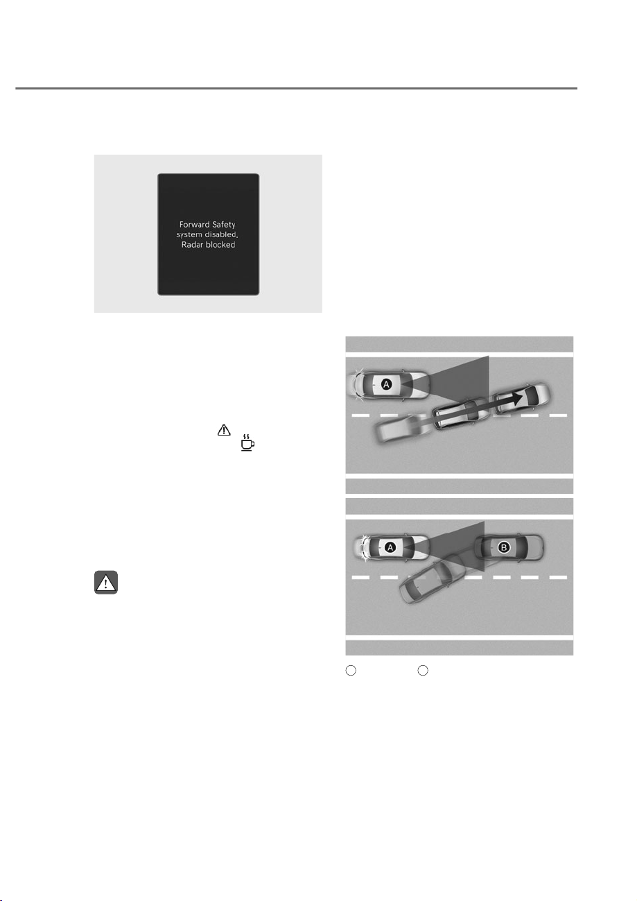
7-69
07
Driver Attention Warning disabled
ORS073214N
ORS073214N
When the front windshield where the
front view camera is located is covered
with foreign material, such as snow
or rain, it can reduce the detecting
performance and temporarily limit or
disable Driver Attention Warning. If this
occurs, the 'Driver Assistance system
limited. Camera obscured.' warning
message, the master (
) warning light,
and the driver’s attention (
) warning
light will appear on the instrument
cluster. Driver Attention Warning will
operate properly when snow, rain or
foreign material is removed. If Driver
Attention Warning does not operate
properly after it is removed, have the
vehicle inspected by an authorized
retailer of Genesis Branded products.
WARNING
• 'ULYHU$WWHQWLRQ:DUQLQJPD\QRW
SURSHUO\RSHUDWHLQDQDUHDIRU
H[DPSOHRSHQWHUUDLQZKHUHDQ\
REMHFWVDUHQRWGHWHFWHGULJKWDIWHU
WXUQLQJ21WKHYHKLFOH
• ,IWKHYHKLFOHLVWXUQHGRIIDQG
restarted while the camera is
REVFXUHGRUPDOIXQFWLRQHGWKH
FRQGLWLRQLVPDLQWDLQHG7KHUHIRUH
'ULYHU$WWHQWLRQ:DUQLQJPD\QRW
RSHUDWHSURSHUO\
Limitations of Driver Attention
Warning
Driver Attention Warning may not work
properly in the following situations:
• The vehicle is driven violently
• The vehicle intentionally crosses over
lanes frequently
• The vehicle is controlled by Driver
Assistance system, such as Lane
Keeping Assist
Leading vehicle departure alert function
• When the vehicle cuts in
ORS072043N
ORS072043N
ORS072070N
ORS072070N
A
: Your vehicle,
B
: Front vehicle
If a vehicle cuts in front of your
vehicle, Leading Departure Alert may
not operate properly.
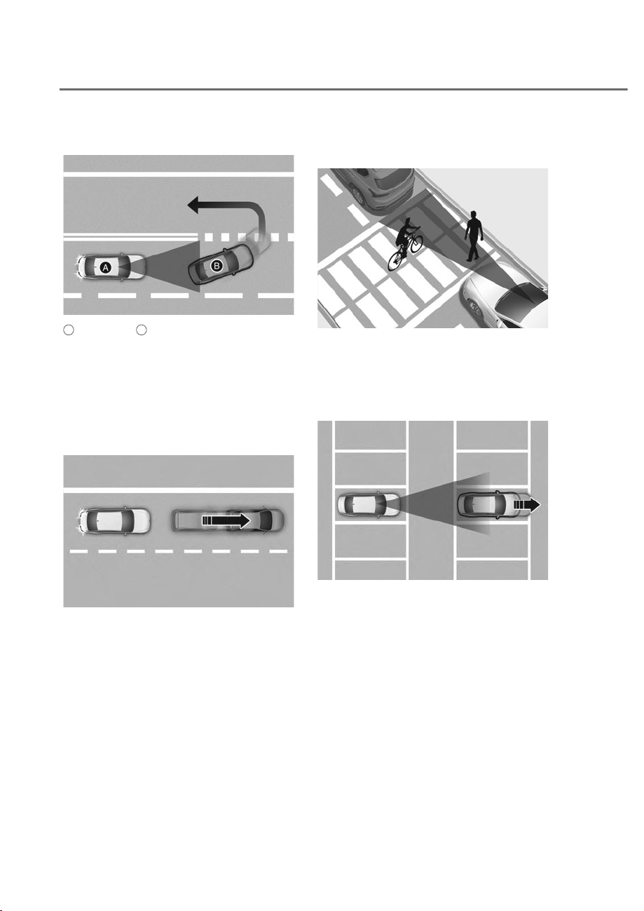
7-70
Driver Assistance System
• When the vehicle ahead sharply steers
ORS071071
ORS071071
A
: Your vehicle,
B
: Front vehicle
If the vehicle in front makes a sharp
turn, such as to turn left or right or
make a U-turn, etc., Leading Vehicle
Departure Alert may not operate
properly.
• When the vehicle ahead abruptly
departures
ORS071072
ORS071072
If the vehicle in front abruptly
departures, Leading Vehicle Departure
Alert may not operate properly.
• When a pedestrian or bicycle is
between you and the vehicle ahead
ORS071073
ORS071073
If there is a pedestrian(s) or bicycle(s)
in between you and the vehicle in
front, Leading Vehicle Departure Alert
may not operate properly.
• When in a parking lot
ORS071045
ORS071045
If a vehicle parked in front drives away
from you, Leading Vehicle Departure
Alert may alert you that the parked
vehicle is driving away.
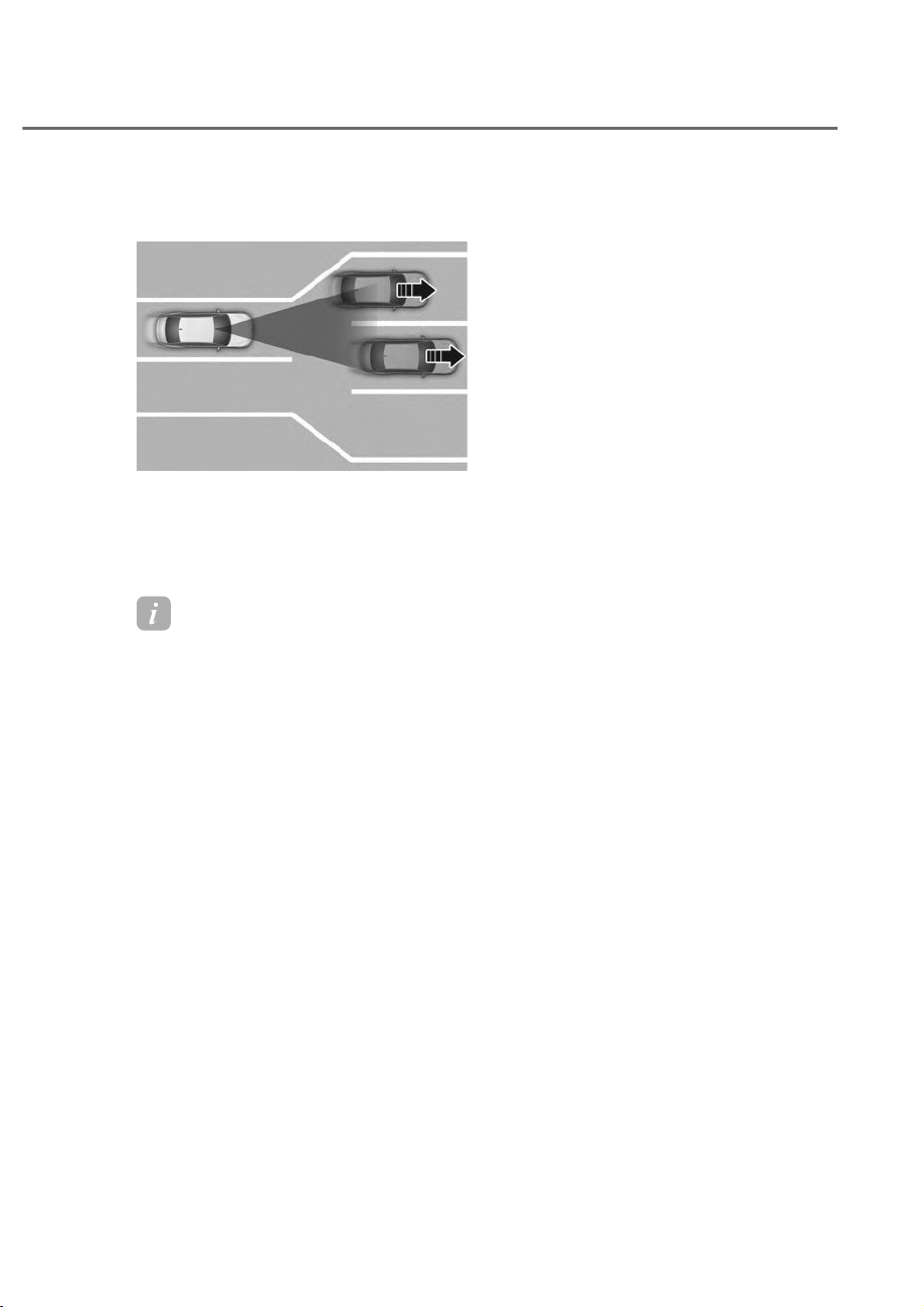
7-71
07
• When driving at a tollgate or
intersection, etc.
ORS071044
ORS071044
If you pass a tollgate or intersection
with lots of vehicles or you drive
where lanes are merged or divided
frequently, Leading Vehicle Departure
Alert may not operate properly.
Information
• For more details on the precautions
of the front view camera, refer to
“Forward ollision-Avoidance Assist
(F A)” section in this chapter.
• Driver Attention Warning may not
operate for 15 seconds after the vehicle
is started, or the front view camera is
initialized.
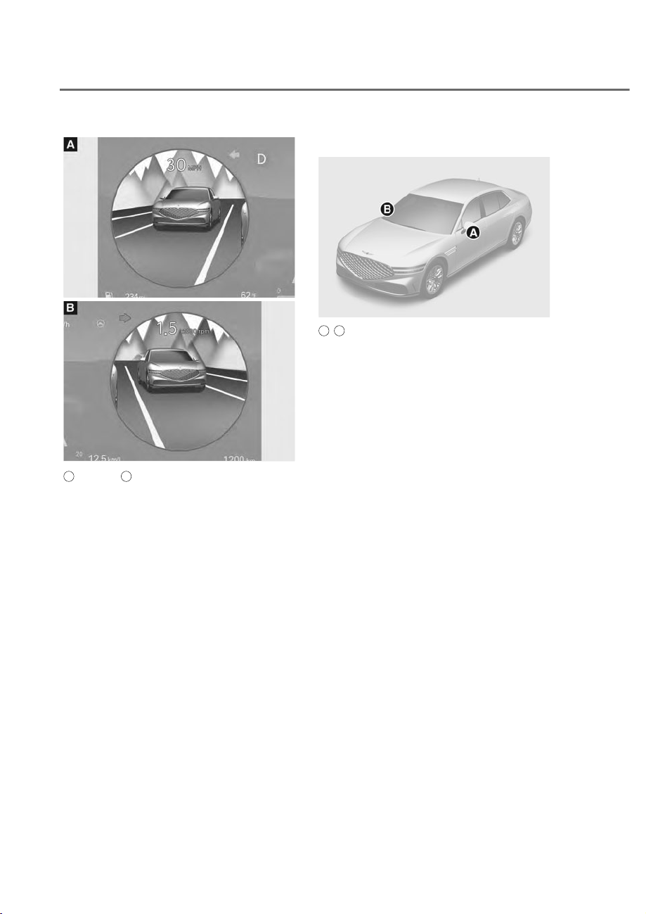
7-72
Driver Assistance System
ORS072028N
ORS072028N
ORS071029L
ORS071029L
A
: Left side,
B
: Right side
Blind-Spot View Monitor uses the wide-
side view cameras to display the rear
blind spot areas of your vehicle on the
instrument cluster when the turn signal is
turned on to help with safe lane changes.
Detecting sensor
ORS071010
ORS071010
A
,
B
: Wide-side view camera
(camera located at bottom of the mirror)
Refer to the picture above for the
detailed location of the detecting
sensors.
%OLQG6SRW9LHZ0RQLWRU
Settings
Setting features
Blind-Spot iew
With the engine on, select ‘Driver
$VVLVWDQFHɌ'ULYLQJ6DIHW\Ɍ%OLQG6SRW
View’ from the Settings menu to turn on
Blind-Spot View Monitor and deselect to
turn off the function.
%/,1'ʏ63279,(:021,725ʚ%90ʛ
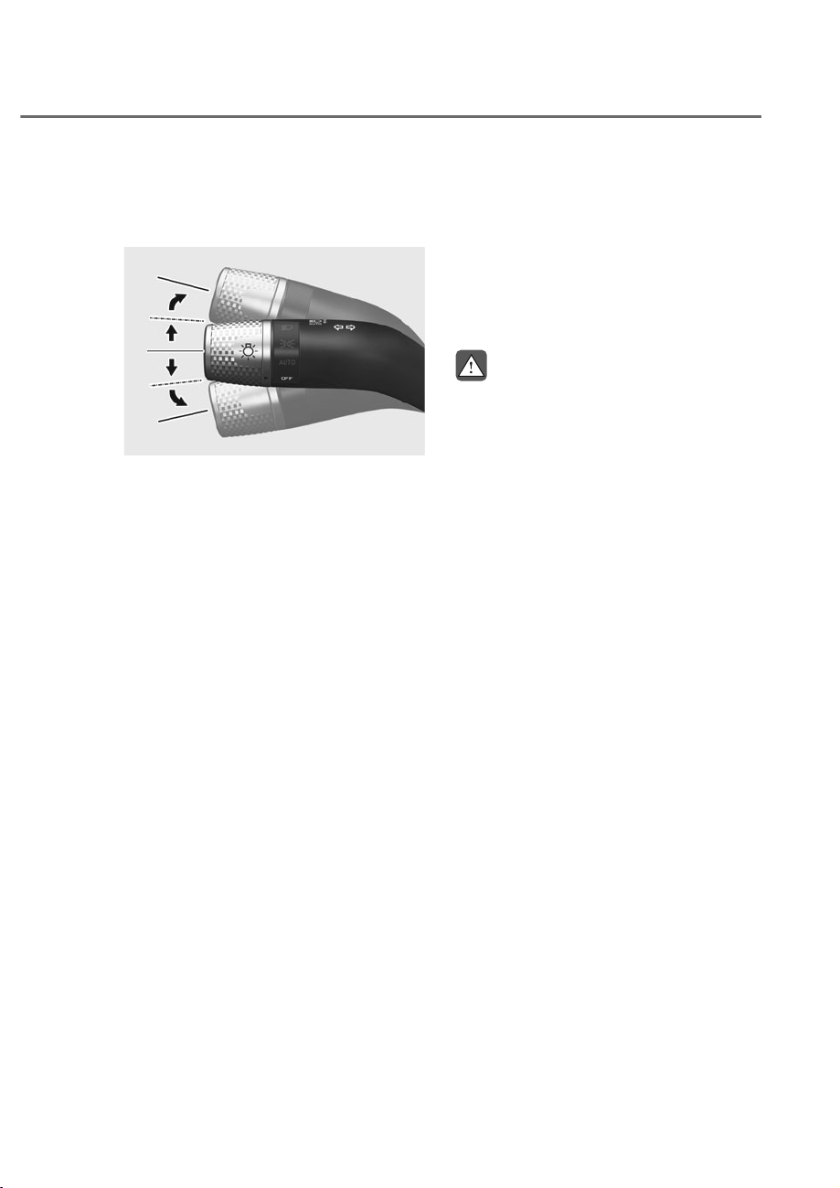
7-73
07
%OLQG6SRW9LHZ0RQLWRU
Operation
Operating switch
ORG3EV071215L
ORG3EV071215L
Turn signal switch
Blind-Spot View Monitor will turn on and
off when the turn signal is turned on and
off.
Blind-Spot View Monitor
perating conditions
When the left or right side turn signal
turns on, the image in that direction is
displayed on the instrument cluster.
ff conditions
• When the turn signal turns off, the
image on the instrument cluster will
turn off.
• When the hazard warning flasher
is on, Blind-Spot View Monitor will
turn off, regardless of the turn signal
status.
• When other important warning is
displayed on the instrument cluster,
Blind-Spot View Monitor may turn off.
%OLQG6SRW9LHZ0RQLWRU
0DOIXQFWLRQ
When Blind-Spot View Monitor is not
working properly, or the cluster display
flickers, or the camera image does
not display properly, have the vehicle
inspected by an authorized retailer of
Genesis Brand products.
WARNING
• 7KHLPDJHVKRZQRQWKHFOXVWHUPD\
differ from the actual distance of the
REMHFW0DNHVXUHWRGLUHFWO\FKHFN
WKHYHKLFOHVVXUURXQGLQJVIRUVDIHW\
• $OZD\VNHHSWKHFDPHUDOHQVFOHDQ
,IWKHOHQVLVFRYHUHGZLWKIRUHLJQ
PDWHULDOLWPD\DGYHUVHO\DIIHFW
camera performance and Blind-
6SRW9LHZ0RQLWRUPD\QRWRSHUDWH
SURSHUO\
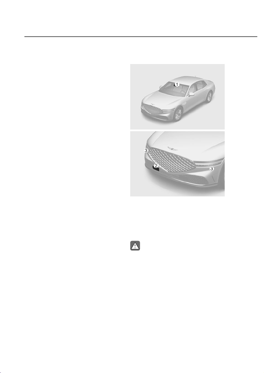
7-74
Driver Assistance System
Smart Cruise Control is designed to
help detect the vehicle ahead and
help maintain the desired speed and
minimum distance between the vehicle
ahead.
2YHUWDNLQJ$FFHOHUDWLRQ$VVLVW
While Smart Cruise Control is operating,
if the function judges that the driver is
determined to overtake the vehicle in
front, acceleration will be assisted.
%DVHGRQ'ULYLQJ6W\OH
Smart Cruise Control will operate based
on the driver’s driving style, such as
inter-vehicle distance, acceleration,
reaction speed.
Detecting sensor
ORS071001
ORS071001
ORS072292
ORS072292
M: Front view camera,
N: Front radar,
O: Front corner radar
The front view camera, front radar and
front corner radar are used as a detecting
sensor to detect front vehicles.
CAUTION
$OZD\VNHHSWKHIURQWYLHZFDPHUD
and front radar in good condition to
maintain optimal performance of Smart
&UXLVH&RQWURO
For more details on the precautions of
WKHIURQWYLHZFDPHUDDQGIURQWUDGDU
UHIHUWRȃ)RUZDUG&ROOLVLRQ$YRLGDQFH
$VVLVW)&$ȄVHFWLRQLQWKLVFKDSWHU
60$57&58,6(&21752/ʚ6&&ʛ
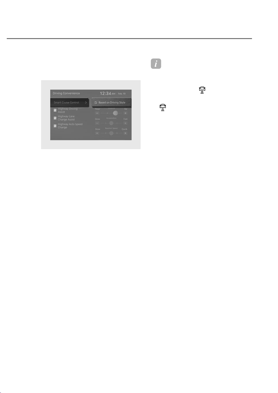
7-75
07
Smart Cruise Control Settings
Based on Driving Style
ORS071258L
ORS071258L
With the engine on, if ‘Driver Assistance
Ɍ'ULYLQJ&RQYHQLHQFHɌ6PDUW&UXLVH
&RQWUROɌ%DVHGRQ'ULYLQJ6W\OHȂLV
selected from the Settings menu, Smart
Cruise Control will operate based on the
driver’s driving style, such as vehicle
distance, acceleration, reaction speed.
Information
• While Smart ruise ontrol is
operating with ‘Based on Driving Style’
selected, if you press and hold the
ehicle Distance (
) button, 'Based
on Driving Style' will deactivate. If you
press and hold the ehicle Distance
(
) button again, 'Driving Style
Setting' will activate.
• Based on Driving Style setting
continuously learns when the driver
drives the vehicle.
• When Based on Driving Style is
deactivated, the driver’s driving style
such as vehicle distance, acceleration,
reaction speed will maintain in the
same stage.
• Even if the steps of the driver’s
driving style such as vehicle distance,
acceleration, reaction speed displayed
when the Base on Driving Style is
activated or deactivated are the same,
the driving style to be controlled may
be differently.

7-76
Driver Assistance System
Warning methods
ORS073334N
ORS073334N
With the engine on, go to 'Driver
$VVLVWDQFHɌ:DUQLQJ0HWKRGVIURPWKH
Settings in the infotainment system to
select the following:
• Warning Volume: The warning volume
can be adjusted. If you turn off the
Warning Volume, for your safety, the
function may warn you with a low
volume.
• Haptic Warning: The steering wheel
vibration can be set.
• Driving Safety Priority: Your vehicle
lowers all other audio volumes when
the Driver Assistance system warning
sounds.
Information
• If you change the Warning Methods,
Warning Methods of other Driver
Assistance systems may change.
• Warning Method will maintain its last
setting even if the vehicle is restarted.
• The setting menu may not be available
for your vehicle depending on the
vehicle features and specifications.
• The Warning olume and Haptic
Warning cannot be turned off at the
same time. When one of the warning is
turned off the other is activated.

7-77
07
Smart Cruise Control Operation
Operating conditions for basic
function
Basic function
Smart Cruise Control operates when the
following conditions are satisfied.
• The gear is in D (Drive)
• Your vehicle speed is within the
operating speed range
- 5-120 mph (10-200 km): when there
is no vehicle in front
- 0-120 mph (0-200 km): when there
is a vehicle in front
• ESC (Electronic Stability Control) or
ABS (Anti-Lock Braking System) is on
Smart Cruise Control does not operate in
the following conditions.
• The driver's door is opened
• Engine RPM is high
• EPB (Electronic Parking Brake) is
applied
• ESC (Electronic Stability Control) or
ABS (Anti-Lock Braking System) is
controlling the vehicle
• Forward Collision-Avoidance Assist
brake control is operating
• Remote Smart Parking Assist brake
control is operating (if equipped)
• Idle Stop and Go system is not
operating
Information
When stopped behind another vehicle, the
driver can turn on Smart ruise ontrol
while the brake pedal is depressed.
Operating conditions for
Acceleration Assist
Overtaking Acceleration Assist operates
when the turn signal indicator is turned
on to the left while Smart Cruise Control
is operating, and the following conditions
are satisfied:
• Your vehicle speed is above 40 mph
(60 km/h)
• A vehicle is detected in front of your
vehicle
Overtaking Acceleration Assist does not
operate in the following conditions.
• The hazard warning flasher is on
• Vehicle speed is reduced to maintain
distance with the vehicle in front
WARNING
,I\RXUYHKLFOHLVDFFHOHUDWLQJ
WHPSRUDULO\GDQJHURXVVLWXDWLRQVPD\
RFFXU$OZD\VFKHFNURDGFRQGLWLRQV
ZKHQDVVLVWHGE\WKH$FFHOHUDWLRQ
$VVLVW
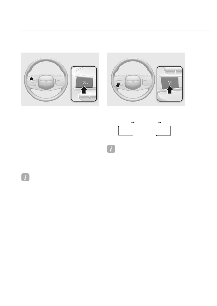
7-78
Driver Assistance System
Turning on Smart Cruise Control
ORS071025
ORS071025
• Press the Driving Assist button to turn
on Smart Cruise Control. The speed
will be set to the current speed on the
cluster.
• If there is no vehicle in front of you,
the set speed will be maintained, but
if there is a vehicle in front of you,
the speed may decrease to maintain
the distance to the vehicle ahead. If
the vehicle ahead accelerates, your
vehicle will travel at a steady cruising
speed after accelerating to the set
speed.
Information
• If your vehicle speed is between 0-20
mph (0-30 km/h) when you press the
Driving Assist button, the set speed will
be set to 20 mph (30 km/h).
• If the vehicle shifted to a low gear, the
vehicle speed may not accelerate to the
set speed.
Setting vehicle distance
ORS071186
ORS071186
Each time the button is pressed, the
headway changes as follows:
Distance 4 Distance 3
Distance 1
Distance 2
Information
• If you drive at 56 mph (90 km/h), the
distance is maintained as follows:
Distance 4 -
approximately 172 ft. (53 m)
Distance 3 -
approximately 130 ft. (40 m)
Distance 2 -
approximately 106 ft. (30 m)
Distance 1 -
approximately 82 ft. (25 m)
• The distance is set to the last set
distance when the engine is restarted,
or when Smart ruise ontrol was
temporarily canceled.
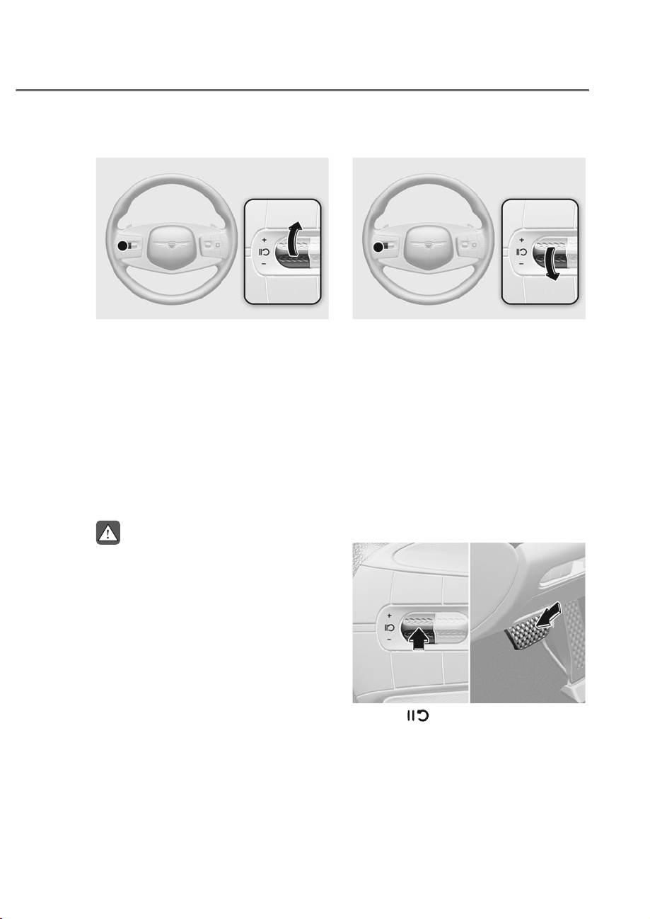
7-79
07
Increasing set speed
ORS071182
ORS071182
• Push the + switch up and release
it immediately. The set speed will
increase by 1 mph (1 km/h) each time
the switch is operated in this manner.
• Push the + switch up and hold it while
monitoring the set speed on the
cluster. The set speed will increase by
5 mph (10 km/h) each time the switch
is operated in this manner. Release
the switch when the desired speed is
shown, and the vehicle will accelerate
to that speed. You can set the speed
to 120 mph (200 km/h).
WARNING
&KHFNWKHGULYLQJFRQGLWLRQEHIRUH
XVLQJWKHVZLWFK'ULYLQJVSHHGPD\
VKDUSO\LQFUHDVHZKHQ\RXSXVKXSDQG
KROGWKHVZLWFK
Decreasing set speed
ORS071183
ORS071183
• Push the - switch down and release
it immediately. The set speed will
decrease by 1 mph (1 km/h) each time
the switch is operated in this manner.
• Push the - switch down and hold it
while monitoring the set speed on the
cluster. The set speed will decrease by
5 mph (10 km/h) each time the switch
is operated in this manner.
Release the switch at the speed you
want to maintain. You can set the
speed to 20 mph (30 km/h).
Temporarily cancelling Smart Cruise
Control
ORS071289L
ORS071289L
Press the switch or depress the
brake pedal to temporarily cancel Smart
Cruise Control.
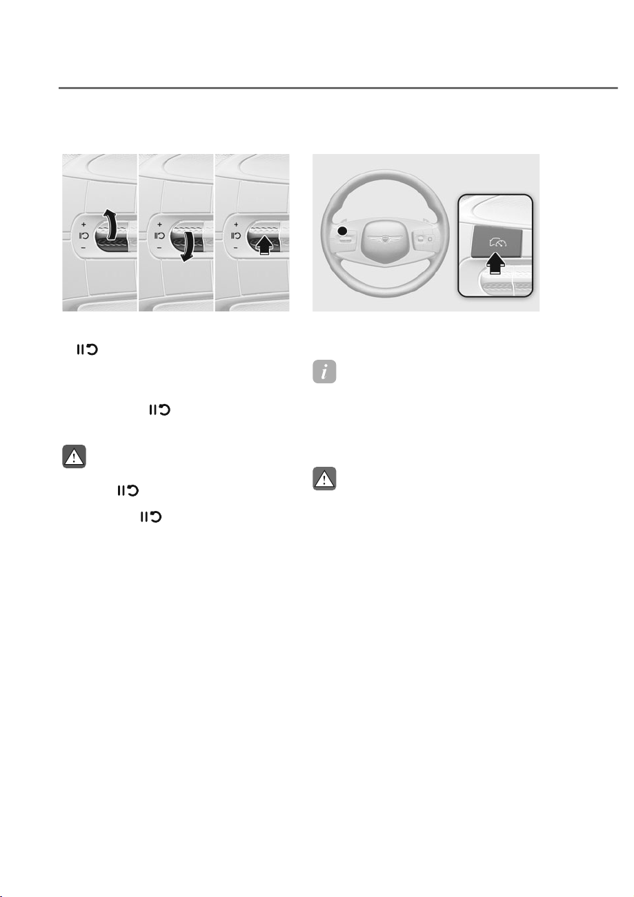
7-80
Driver Assistance System
Resuming Smart Cruise Control
ORS071184
ORS071184
To resume Smart Cruise Control after the
function was canceled, operate the +, -
or
switch.
If you push the + switch up or - switch
down, vehicle speed will be set to the
current speed on the cluster.
If you press the
switch, vehicle
speed will resume to the preset speed.
WARNING
&KHFNWKHGULYLQJFRQGLWLRQEHIRUH
using the
VZLWFK'ULYLQJVSHHG
PD\VKDUSO\LQFUHDVHRUGHFUHDVHZKHQ
\RXSUHVVWKH
VZLWFK
Turning off Smart Cruise Control
ORS071025
ORS071025
Press the Driving Assist button to turn
Smart Cruise Control off.
Information
If your vehicle is equipped with Manual
Speed Limit Assist, press and hold the
Driving Assist button to turn off Smart
ruise ontrol. However Manual Speed
Limit Assist will turn on.
CAUTION
'RQRWXVHWKHVZLWFKHVDQGEXWWRQV
DWWKHVDPHWLPH6PDUW&UXLVH&RQWURO
PD\QRWRSHUDWHSURSHUO\
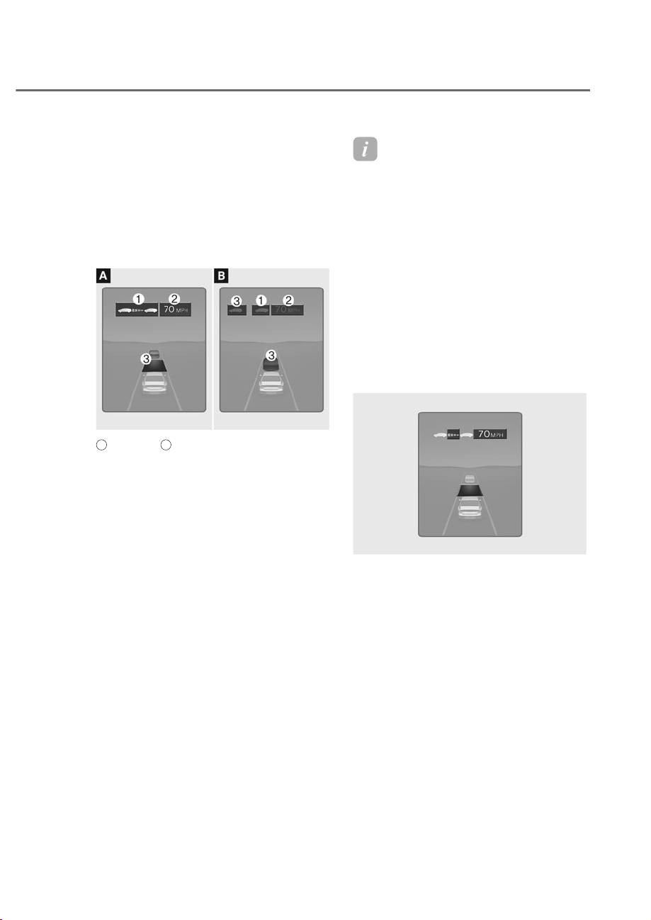
7-81
07
Displaying operating status
You can see the status of the Smart
Cruise Control operation in the Driving
Assist view on the cluster. Refer to “View
Modes” section in chapter 4.
Smart Cruise Control will be displayed
as below depending on the status of the
function.
ORS072145N
ORS072145N
A
: Operating,
B
: Temporarily canceled
• When operating
(1) Whether there is a vehicle ahead
and the selected distance level
(2) Set speed
(3) Whether there is a vehicle ahead
and the target vehicle distance
• When temporarily canceled
(1) Your vehicle (gray)
(2) Previous set speed (gray)
(3) Vehicle ahead and distance level
(gray)
Information
• The distance of the front vehicle on the
cluster is displayed according to the
actual distance between your vehicle
and the vehicle ahead.
• The target distance may vary according
to the vehicle speed and the set
distance level. If the vehicle speed is
low, even though the vehicle distance
have changed, the change of the target
vehicle distance may be small.
• The images and colors in the
instrument cluster may differ
depending on the cluster type or theme
selected from the settings menu.
Accelerating temporarily
ORS072147N
ORS072147N
If you want to speed up temporarily
without altering the set speed while
Smart Cruise Control is operating,
depress the accelerator pedal. While the
accelerator pedal is depressed, the set
speed, distance level and target distance
will blink on the cluster.
However, if the accelerator pedal is
depressed insufficiently, the vehicle may
decelerate.
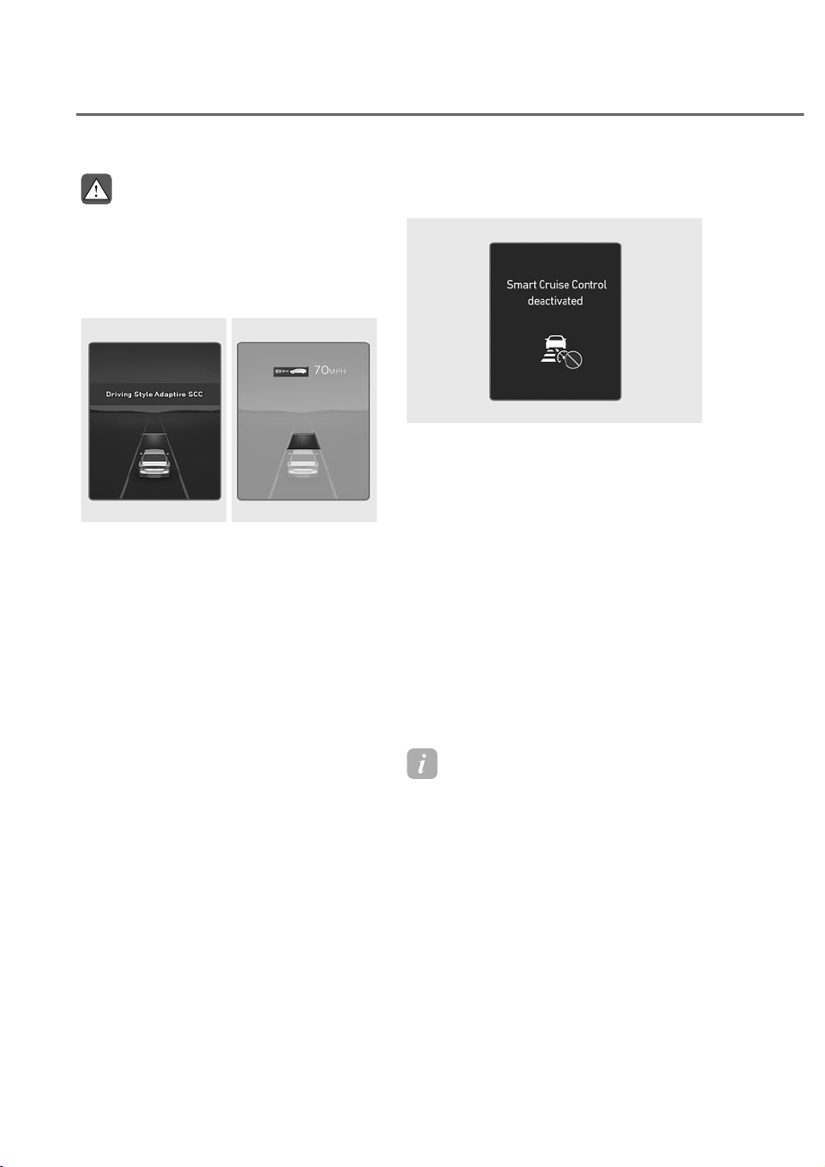
7-82
Driver Assistance System
WARNING
Be careful when accelerating
WHPSRUDULO\EHFDXVHWKHVSHHGDQG
GLVWDQFHLVQRWFRQWUROOHGDXWRPDWLFDOO\
HYHQLIWKHUHLVDYHKLFOHLQIURQWRI\RX
Based on Driving Style operation
ORS071094L
ORS071094L
ORS072148N
ORS072148N
When Based on Driving Style is
operating, ‘Driving Style Adaptive SCC’
message will appear on the cluster for
2 seconds, and the distance level and
target distance will be displayed based
on the driving style.
Temporarily cancelling Smart Cruise
Control
ORS071118L
ORS071118L
Smart Cruise Control will be temporarily
canceled automatically when:
• The vehicle speed is above 130 mph
(210 km/h)
• The vehicle is stopped for a certain
period of time
• The accelerator pedal is continuously
depressed for a certain period of time
• The conditions for Smart Cruise
Control to operate is not satisfied
If Smart Cruise Control is temporarily
canceled automatically, the ‘Smart
Cruise Control deactivated’ warning
message will appear on the cluster, and
an audible warning will sound to warn
the driver.
Information
If Smart ruise ontrol is temporarily
canceled while the vehicle is at a
standstill with the function activated,
EPB (Electronic Parking Brake) maybe
applied.
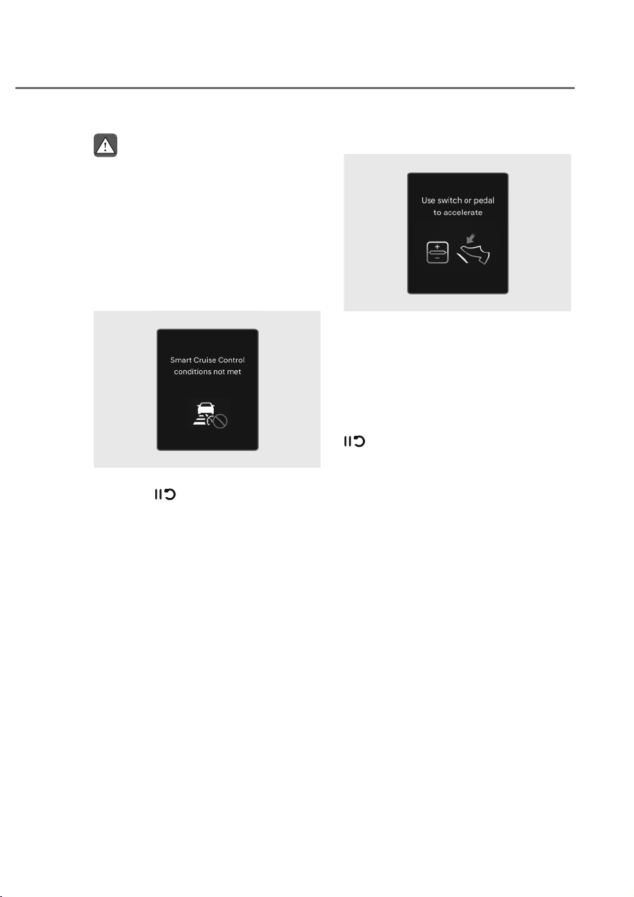
7-83
07
WARNING
When Smart Cruise Control is
WHPSRUDULO\FDQFHOHGGLVWDQFHZLWKWKH
IURQWYHKLFOHZLOOQRWEHPDLQWDLQHG
$OZD\VKDYH\RXUH\HVRQWKHURDG
ZKLOHGULYLQJDQGLIQHFHVVDU\GHSUHVV
WKHEUDNHSHGDOWRUHGXFH\RXUGULYLQJ
speed in order to maintain a safe
GLVWDQFH
Smart Cruise Control conditions not
satisfied
OTM070112N
OTM070112N
If the Driving Assist button, + switch,
- switch or
switch is pushed
when Smart Cruise Control operating
conditions are not satisfied, the ‘Smart
Cruise Control conditions not met’ will
appear on the cluster, and an audible
warning will sound.
In traffic situation
OTM070114L
OTM070114L
In traffic, your vehicle will stop if the
vehicle ahead of you stops. Also, if the
vehicle ahead of you starts moving, your
vehicle will start as well. In addition, after
the vehicle has stopped and a certain
time have passed, the ‘Use switch or
pedal to accelerate’ message will appear
on the cluster. Depress the accelerator
pedal or operate the + switch, - switch or
switch to start driving.
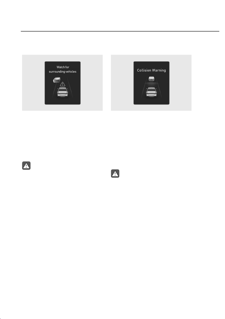
7-84
Driver Assistance System
Warning road conditions ahead
ORS071120L
ORS071120L
In the following situation, the ‘Watch for
surrounding vehicles’ warning message
will appear on the cluster, and an audible
warning will sound to warn the driver of
road conditions ahead.
• The vehicle in front disappears when
Smart Cruise Control is maintaining
the distance with the vehicle ahead
while driving below a certain speed.
WARNING
$OZD\VSD\DWWHQWLRQWRYHKLFOHVRU
REMHFWVWKDWPD\VXGGHQO\DSSHDULQ
IURQWRI\RXDQGLIQHFHVVDU\GHSUHVV
WKHEUDNHSHGDOWRUHGXFH\RXUGULYLQJ
speed in order to maintain a safe
GLVWDQFH
Collision Warning
ORS071096L
ORS071096L
While Smart Cruise Control is operating,
when the collision risk with the vehicle
ahead is high, the ‘Collision Warning’
warning message will appear on the
cluster. Also an audible warning will
sound and the steering wheel will vibrate
to warn the driver. Always have your
eyes on the road while driving, and if
necessary, depress the brake pedal to
reduce your driving speed in order to
maintain a safe distance.
WARNING
,QWKHIROORZLQJVLWXDWLRQV6PDUW&UXLVH
&RQWUROPD\QRWZDUQWKHGULYHURID
FROOLVLRQ
• 7KHGLVWDQFHIURPWKHIURQWYHKLFOH
LVQHDURUWKHYHKLFOHVSHHGRIWKH
IURQWYHKLFOHLVIDVWHURUVLPLODUWR
\RXUYHKLFOH
• 7KHVSHHGRIWKHIURQWYHKLFOHLVYHU\
slow or is at a standstill
• The accelerator pedal is depressed
right after Smart Cruise Control is
turned on

7-85
07
WARNING
Take the following precautions when
using Smart Cruise Control:
• Smart Cruise Control does not
VXEVWLWXWHIRUSURSHUDQGVDIH
GULYLQJ,WLVWKHUHVSRQVLELOLW\RIWKH
GULYHUWRDOZD\VFKHFNWKHVSHHGDQG
GLVWDQFHWRWKHYHKLFOHDKHDG
• 6PDUW&UXLVH&RQWUROPD\QRW
UHFRJQL]HXQH[SHFWHGDQGVXGGHQ
VLWXDWLRQVRUFRPSOH[GULYLQJ
VLWXDWLRQVVRDOZD\VSD\DWWHQWLRQWR
GULYLQJFRQGLWLRQVDQGFRQWURO\RXU
YHKLFOHVSHHG
• .HHS6PDUW&UXLVH&RQWURORIIZKHQ
WKHIXQFWLRQLVQRWLQXVHWRDYRLG
LQDGYHUWHQWO\VHWWLQJDVSHHG
• 'RQRWRSHQWKHGRRURUOHDYHWKH
YHKLFOHZKHQ6PDUW&UXLVH&RQWURO
LVRSHUDWLQJHYHQLIWKHYHKLFOHLV
VWRSSHG
• $OZD\VEHDZDUHRIWKHVHOHFWHG
VSHHGDQGKHDGZD\GLVWDQFH
• .HHSDVDIHGLVWDQFHDFFRUGLQJWR
URDGFRQGLWLRQVDQGYHKLFOHVSHHG
,IWKHKHDGZD\GLVWDQFHLVWRRFORVH
GXULQJKLJKVSHHGGULYLQJDVHULRXV
FROOLVLRQPD\UHVXOW
• When maintaining distance with
WKHYHKLFOHDKHDGLIWKHIURQW
YHKLFOHGLVDSSHDUV6PDUW&UXLVH
&RQWUROPD\VXGGHQO\DFFHOHUDWHWR
WKHVHWVSHHG$OZD\VEHDZDUHRI
XQH[SHFWHGDQGVXGGHQVLWXDWLRQV
IURPRFFXUULQJ
• 9HKLFOHVSHHGPD\GHFUHDVHRQDQ
upward slope and increase on a
GRZQZDUGVORSH
• $OZD\VEHDZDUHRIVLWXDWLRQVVXFK
DVZKHQDYHKLFOHFXWVLQVXGGHQO\
• :KHQ\RXDUHWRZLQJDWUDLOHURU
DQRWKHUYHKLFOHWXUQRII6PDUW
&UXLVH&RQWUROIRUVDIHW\UHDVRQV
• Turn off Smart Cruise Control when
\RXUYHKLFOHLVEHLQJWRZHG
• 6PDUW&UXLVH&RQWUROPD\QRW
RSHUDWHSURSHUO\LILQWHUIHUHGE\
VWURQJHOHFWURPDJQHWLFZDYHV
• 6PDUW&UXLVH&RQWUROPD\QRW
GHWHFWDQREVWDFOHLQIURQWDQGOHDG
WRDFROOLVLRQ$OZD\VORRNDKHDG
FDXWLRXVO\WRSUHYHQWXQH[SHFWHG
and sudden situations from
RFFXUULQJ
• 9HKLFOHVPRYLQJLQIURQWRI\RXZLWK
DIUHTXHQWODQHFKDQJHPD\FDXVH
DGHOD\LQ6PDUW&UXLVH&RQWURO
UHDFWLRQRUPD\FDXVH6PDUW&UXLVH
&RQWUROWRUHDFWWRDYHKLFOHDFWXDOO\
LQDQDGMDFHQWODQH$OZD\VGULYH
FDXWLRXVO\WRSUHYHQWXQH[SHFWHG
and sudden situations from
RFFXUULQJ
• $OZD\VEHDZDUHRIWKHVXUURXQGLQJV
DQGGULYHVDIHO\HYHQWKRXJKD
warning message does not appear or
DQDXGLEOHZDUQLQJGRHVQRWVRXQG
• ,IDQ\RWKHUV\VWHPȂVZDUQLQJ
PHVVDJHLVGLVSOD\HGRUZDUQLQJ
VRXQGLVJHQHUDWHG6PDUW&UXLVH
&RQWUROZDUQLQJPHVVDJHPD\QRW
EHGLVSOD\HGDQGZDUQLQJVRXQGPD\
QRWEHJHQHUDWHG
• <RXPD\QRWKHDUWKHZDUQLQJVRXQG
RI)RUZDUG&ROOLVLRQ$YRLGDQFH
$VVLVWLIWKHVXUURXQGLQJLVQRLV\
• 7KHYHKLFOHPDQXIDFWXUHULVQRW
UHVSRQVLEOHIRUDQ\WUDIILFYLRODWLRQ
RUDFFLGHQWVFDXVHGE\WKHGULYHU
• $OZD\VVHWWKHYHKLFOHVSHHGXQGHU
WKHVSHHGOLPLWLQ\RXUDUHD
• 9HKLFOHGLVWDQFHDFFHOHUDWLRQDQG
UHDFWLRQVSHHGPD\FKDQJHLIWKH
GULYHUȂVGULYLQJVW\OHFKDQJHV
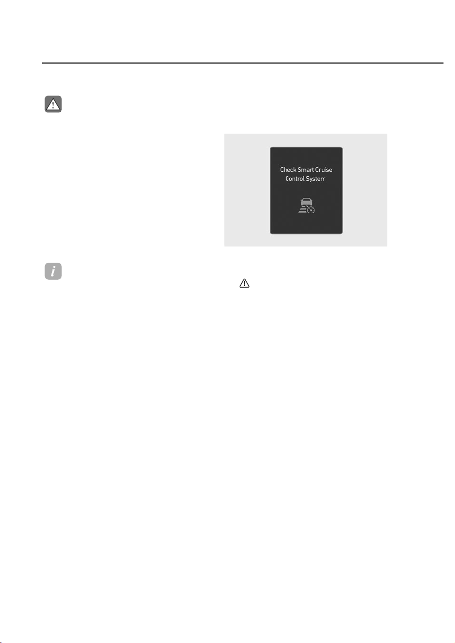
7-86
Driver Assistance System
CAUTION
• 7KHYHKLFOHPXVWEHGULYHQ
VXIILFLHQWO\WRUHIOHFWWKHDFWXDO
GULYLQJVW\OHRIWKHGULYHUVXFKDV
LQWHUYHKLFOHGLVWDQFHDFFHOHUDWLRQ
DQGUHDFWLRQVSHHG
• %DVHGRQ'ULYLQJVW\OHGRHVQRW
UHIOHFWZKHWKHUWKHGULYHUKDV
changed when determining the
GULYHUVGULYLQJVW\OH
• ,I\RXDUHGULYLQJLQVSHFLDO
FRQGLWLRQVVXFKDVVQRZUDLQIRJ
RUVWHHSVORSHVWKHYHKLFOHPD\QRW
EHGULYHQDFFRUGLQJWRWKHGULYHUȂV
GULYLQJVW\OH
Information
• Smart ruise ontrol may not operate
for 15 seconds after the vehicle is
started or the front view camera or
front radar is initialized.
• You may hear a sound when the brake
is controlled by Smart ruise ontrol.
• Based on Driving Style may not reflect
the driver’s driving style or driving
conditions that affects driving safety.
• Based on Driving Style does not reflect
any other driving style other than
inter-vehicle distance, acceleration and
reaction speed.
Smart Cruise Control
0DOIXQFWLRQDQG/LPLWDWLRQV
Smart Cruise Control malfunction
ORS071121L
ORS071121L
When Smart Cruise Control is not working
properly, the ‘Check Smart Cruise Control
System’ warning message will appear, and
the
warning light will illuminate on the
instrument cluster. If this occurs, have the
vehicle inspected by an authorized retailer
of Genesis Branded products.
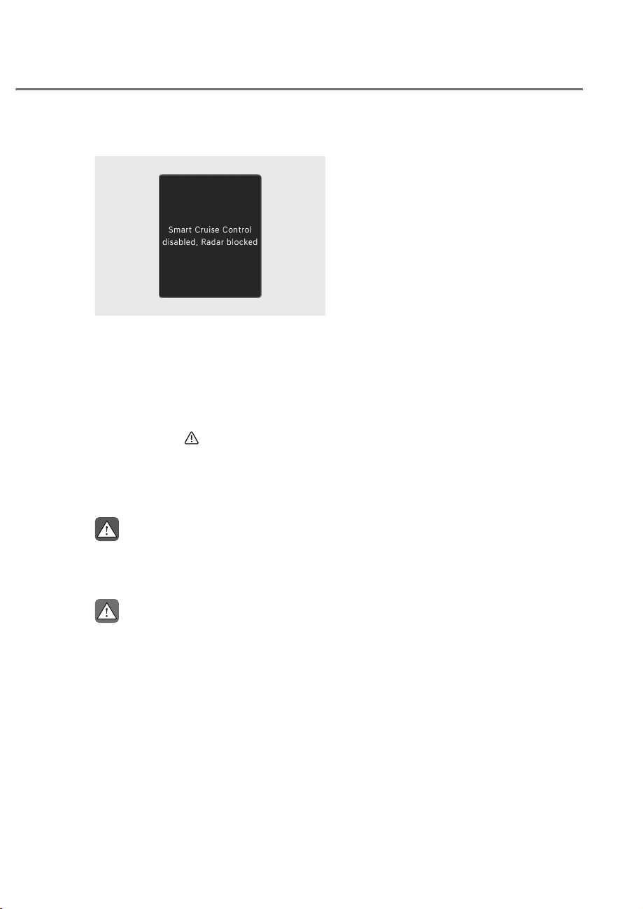
7-87
07
Smart Cruise Control disabled
OTM070115N
OTM070115N
When the front radar cover or sensor
is covered with snow, rain, or foreign
material, it can reduce the detecting
performance and temporarily limit or
disable Smart Cruise Control.
If this occurs the ‘Smart Cruise Control
disabled. Radar blocked’ warning
message will appear for a certain period
of time, and the
warning light will
illuminate on the instrument cluster.
Smart Cruise Control will operate properly
when snow, rain or foreign material is
removed.
WARNING
(YHQWKRXJKWKHZDUQLQJPHVVDJHGRHV
QRWDSSHDURQWKHFOXVWHU6PDUW&UXLVH
&RQWUROPD\QRWSURSHUO\RSHUDWH
CAUTION
6PDUW&UXLVH&RQWUROPD\QRWSURSHUO\
RSHUDWHLQDQDUHDIRUH[DPSOHRSHQ
WHUUDLQZKHUHDQ\REMHFWVDUHQRW
GHWHFWHGDIWHUWXUQLQJ21WKHHQJLQH
Limitations of Smart Cruise Control
Smart Cruise Control may not operate
properly, or it may operate unexpectedly
under the following circumstances:
• The detecting sensor or the
surroundings are contaminated or
damaged
• Washer fluid is continuously sprayed,
or the wiper is on
• The camera lens is contaminated due
to tinted, filmed or coated windshield,
damaged glass, or sticky foreign
material (sticker, bug, etc.) on the
glass
• Moisture is not removed or frozen on
the windshield
• The field of view of the front view
camera is obstructed by sun glare
• Street light or light from an oncoming
vehicle is reflected on the wet road
surface, such as a puddle on the road
• The temperature around the front
view camera is high or low
• An object is placed on the dashboard
• The surrounding is very bright
• The surrounding is very dark, such as
in a tunnel, etc.
• The brightness changes suddenly, for
example when entering or exiting a
tunnel
• The brightness outside is low, and the
headlamps are not on or are not bright
• Driving in heavy rain or snow, or thick
fog
• Driving through steam, smoke or
shadow

7-88
Driver Assistance System
• Only part of the vehicle is detected
• The vehicle in front has no tail lights,
tail lights are located unusually, etc.
• The brightness outside is low, and the
tail lamps are not on or are not bright
• The rear of the front vehicle is small
or does not look normal (for example,
tilted, overturned, etc.)
• The front vehicle’s ground clearance is
low or high
• A vehicle suddenly cuts in front
• Your vehicle is being towed
• Driving through a tunnel or iron bridge
• Driving near areas containing metal
substances, such as a construction
zone, railroad, etc.
• An object reflecting off the front radar
such as a guardrail, nearby vehicle,
etc.
• The bumper around the front radar is
impacted, damaged or the front radar
is out of position
• The temperature around the front
radar is high or low
• Driving in vast areas where there
are few vehicles or structures (for
example, desert, meadow, suburb,
etc.)
• The vehicle in front is made of
material that does not reflect on the
front radar
• Driving near a highway interchange or
tollgate
• Driving on a slippery surface due to
snow, water puddle, ice, etc.
• Driving on a curved road
• The vehicle in front is detected late
• The vehicle in front is suddenly
blocked by an obstacle
• The vehicle in front suddenly changes
lane or suddenly reduces speed
• The vehicle in front is bent out of
shape
• The front vehicle’s speed is fast or
slow
• With a vehicle in front, your vehicle
changes lane at low speed
• The vehicle in front is covered with
snow
• Unstable driving
• You are on a roundabout and the
vehicle in front is not detected
• You are continuously driving in a circle
• Driving in a parking lot
• Driving through a construction area,
unpaved road, partial paved road,
uneven road, speed bumps, etc.
• Driving on an incline road, curved
road, etc.
• Driving through a roadside with trees
or streetlights
• The adverse road conditions cause
excessive vehicle vibrations while
driving
• Your vehicle height is low or high
due to heavy loads, abnormal tire
pressure, etc.
• Driving through a narrow road where
trees or grass are overgrown
• There is interference by
electromagnetic waves, such as
driving in an area with strong radio
waves or electrical noise
• Rear wheel steering system (if
equipped) is disabled
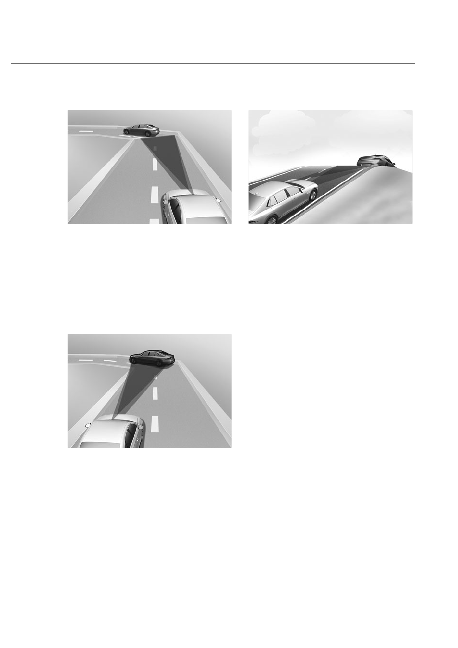
7-89
07
• Driving on a curved road
ORS071061
ORS071061
On curves, Smart Cruise Control may
not detect a vehicle in the same lane,
and may accelerate to the set speed.
Also, vehicle speed may rapidly
decrease when the vehicle ahead is
detected suddenly.
Select the appropriate set speed on
curves and apply the brake pedal or
accelerator pedal according to the
road and driving conditions ahead.
ORS071064
ORS071064
Your vehicle speed can be reduced
due to a vehicle in the adjacent lane.
Apply the accelerator pedal and select
the appropriate set speed. Check
to be sure that the road conditions
permit safe operation of Smart Cruise
Control.
• Driving on an inclined road
ORS071067
ORS071067
During uphill or downhill driving,
Smart Cruise Control may not detect
a moving vehicle in your lane, and
cause your vehicle to accelerate to
the set speed. Also, vehicle speed will
rapidly decrease when the vehicle
ahead is detected suddenly.
Select the appropriate set speed on
inclines and apply the brake pedal or
accelerator pedal according to the
road and driving conditions ahead.
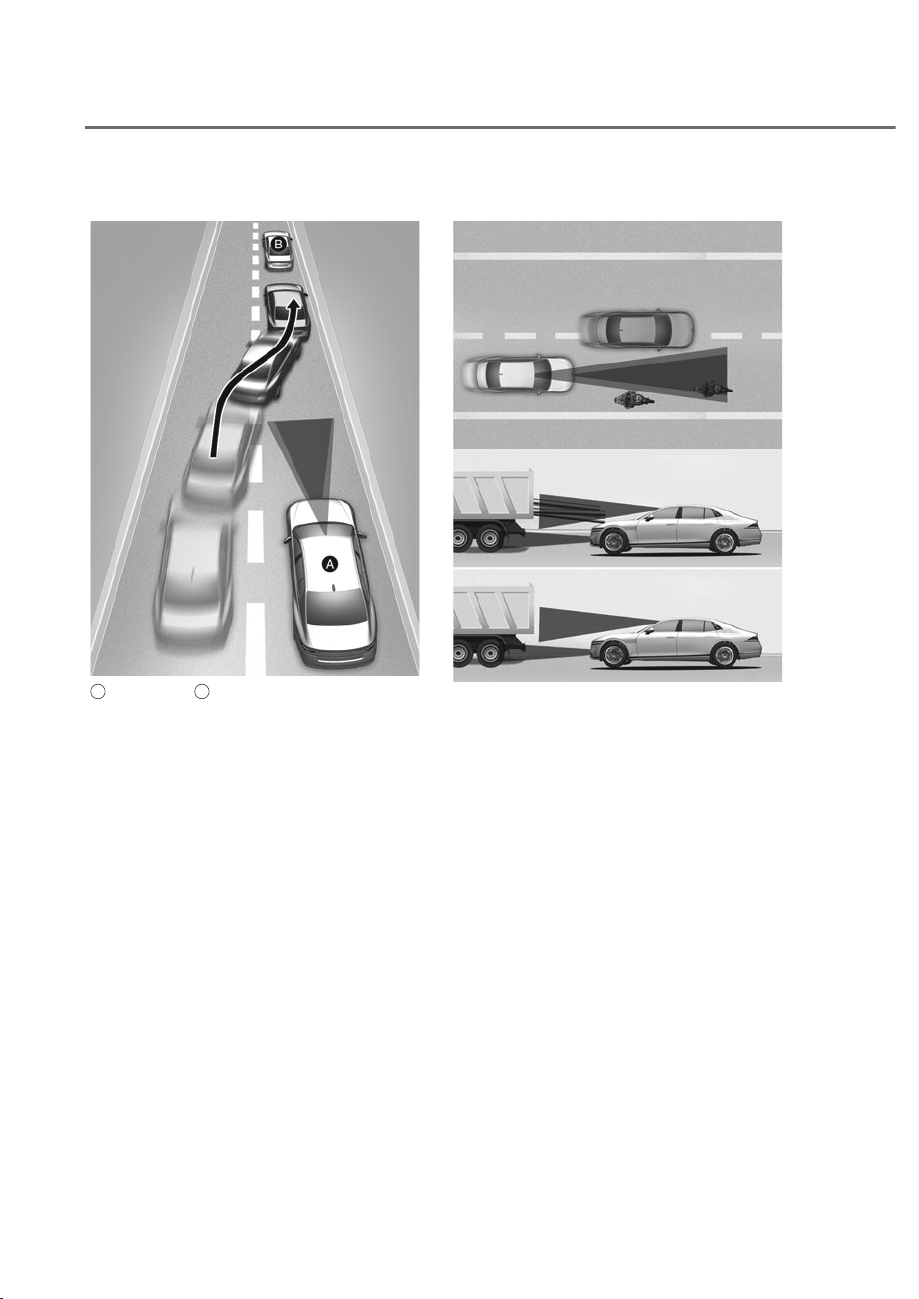
7-90
Driver Assistance System
• Changing lanes
ORS071194
ORS071194
A
: Your vehicle,
B
: Lane changing vehicle
When a vehicle moves into your lane
from an adjacent lane, it cannot be
detected by the sensor until it is in the
sensor's detection range. Smart Cruise
Control may not immediately detect
the vehicle when the vehicle changes
lanes abruptly. In this case, you must
maintain a safe braking distance, and
if necessary, depress the brake pedal
to reduce your driving speed in order
to maintain a safe distance.
• Situations when detecting are limited
ORS071046
ORS071046
ORS071047
ORS071047
In the following cases, some vehicles,
pedestrians or animals in your lane
cannot be detected by the sensor:
- Vehicles offset to one side
- Slow-moving vehicles or sudden-
decelerating vehicles
- Vehicles with higher ground
clearance or vehicles carrying loads
that stick out of the back of the
vehicle
- Vehicles that has the front lifted
dueto heavy loads
- Vehicles within approximately 6 ft.
(2m) from your vehicle
- Oncoming vehicles
- Stopped vehicles
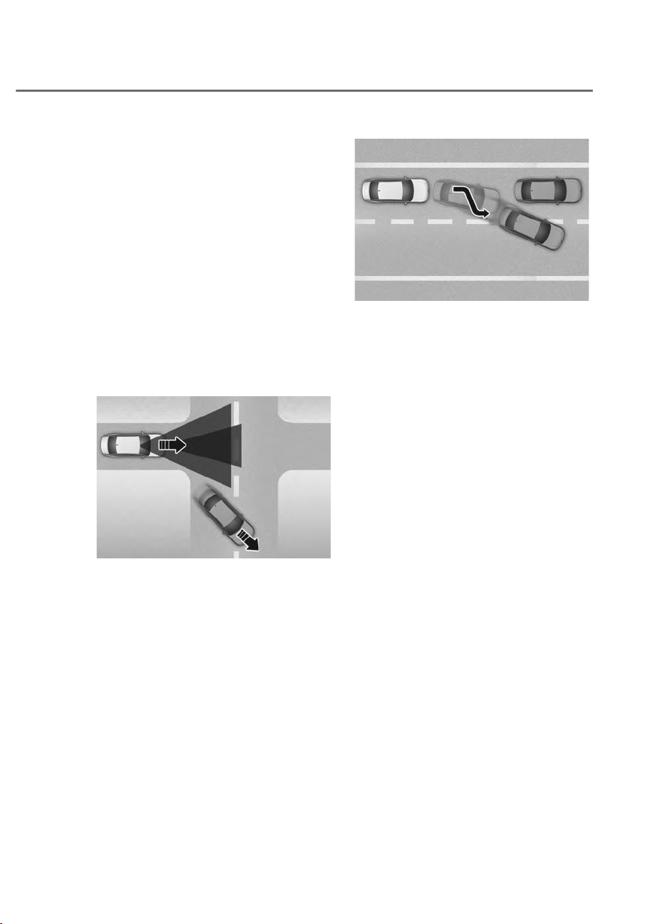
7-91
07
- Vehicles with small rear profile, such
as trailers
- Narrow vehicles, such as
motorcycles or bicycles
- Special vehicles
- Animals and pedestrians
Adjust your vehicle speed by
depressing the brake pedal according
to the road and driving conditions
ahead.
In the following cases, the vehicle
in front cannot be detected by the
sensor:
- You are steering your vehicle
- Driving on narrow or sharply curved
roads
ORS071177
ORS071177
• When a vehicle ahead disappears
at an intersection, your vehicle may
accelerate.
Always pay attention to road and
driving conditions while driving.
ORS071084
ORS071084
• When a vehicle in front of you merges
out of the lane, Smart Cruise Control
may not immediately detect the new
vehicle that is now in front of you.
Always pay attention to road and
driving conditions while driving.
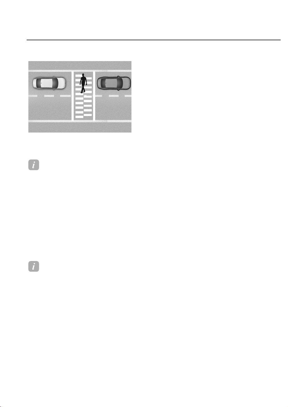
7-92
Driver Assistance System
ORS071038
ORS071038
• Always look out for pedestrians when
your vehicle is maintaining a distance
with the vehicle ahead.
Information
This device complies with Part 15 of the
F rules. peration is sub ect to the
following three conditions:
1. This device may not cause harmful
interference, and
2. This device must accept any
interference received, including
interference that may cause undesired
operation.
3. hanges or modifications not expressly
approved by the party responsible
for compliance could void the user’s
authority to operate the device.
Information
Radio frequency radiation exposure
information:
This equipment complies with F
radiation exposure limits set forth for an
uncontrolled environment.This equipment
should be installed and operated with
minimum distance of 8 in. (20 cm) between
the radiator (antenna) and your body.
This transmitter must not be co-located or
operating in con unction with any other
antenna or transmitter.
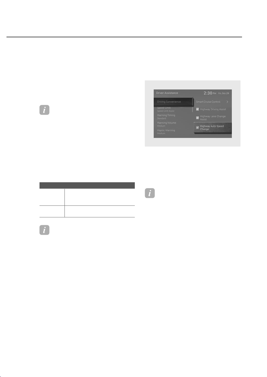
7-93
07
Navigation-based Smart Cruise Control
helps maintain an optimum speed
depending on the road conditions by
using information from the navigation
system when driving on highways while
Smart Cruise Control is operating.
Information
• Navigation-based Smart ruise ontrol
is available only on controlled access
road of certain highways.
à ontrolled access road indicates
roads with limited entrances and
exits that allow uninterrupted high
speed traffic flow. nly passenger
cars and motorcycles are allowed on
controlled access roads.
• Additional highways may be expanded
by future navigation updates.
$YDLODEOHKLJKZD\&RQWUROOHGDFFHVVURDG
USA
Select Interstate Highway and
U.S. (Federal) and State
Highways
Canada
Select Provincial and
Territorial Highways
Information
Navigation-based Smart ruise ontrol
operates on main roads of highways,
and does not operate on interchanges or
unctions.
1DYLJDWLRQ%DVHG6PDUW&UXLVH
Control Settings
ORS071274L
ORS071274L
With the engine on, select ‘Driver
$VVLVWDQFHɌ'ULYLQJ&RQYHQLHQFHɌ
Highway Auto Speed Change’ from the
Settings menu to turn on Navigation-
based Smart Cruise Control and deselect
to turn off the function.
Information
When there is a problem with Navigation-
based Smart ruise ontrol, the function
cannot be set from the Settings menu.
1$9,*$7,21ʏ%$6('60$57&58,6(&21752/ʚ16&&ʛ
ʚ,)(48,33('ʛ
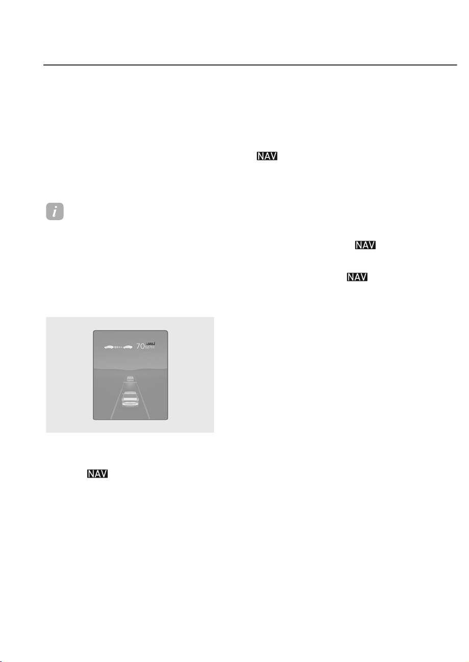
7-94
Driver Assistance System
1DYLJDWLRQ%DVHG6PDUW&UXLVH
Control Operation
Operating conditions
Navigation-based Smart Cruise Control
is ready to operate if all of the following
conditions are satisfied:
• Smart Cruise Control is operating
• Driving on main roads of highways
Information
For more details on how to operate Smart
ruise ontrol, refer to “Smart ruise
ontrol (S )” section in this chapter.
Navigation-based Smart Cruise
Control display and control
When Navigation-based Smart Cruise
Control operates, it will be displayed on
the cluster as follows:
ORS072150N
ORS072150N
Navigation-based Smart ruise ontrol
standby
If the operating conditions are satisfied,
the green
symbol will illuminate.
Navigation-based Smart ruise ontrol
operating
If temporary deceleration is required in
the standby state and Navigation-based
Smart Cruise Control is operating, the
green
symbol will blink on the
cluster.
Temporarily canceled or interrupted by
the driver
If Navigation-based Smart Cruise Control
cannot control the vehicle, such as when
Smart Cruise Control is temporarily
canceled or the navigation system is
searching for a route, the gray
indicator light illuminates.
When the driver depresses the
accelerator pedal, the white
indicator light blinks.

7-95
07
WARNING
ORS072095N
ORS072095N
ȁ'ULYHFDUHIXOO\ȂZDUQLQJPHVVDJHZLOO
appear in the following circumstances:
- 1DYLJDWLRQEDVHG6PDUW&UXLVH
&RQWUROLVQRWDEOHWRVORZGRZQ\RXU
YHKLFOHWRDVDIHVSHHG
Information
The images and colors in the instrument
cluster may differ depending on the cluster
type or theme selected from the settings
menu.
Highway urve one Auto Slowdown
• Depending on the curve ahead on the
highway, the vehicle will decelerate,
and after passing the curve, the
vehicle will accelerate to Smart Cruise
Control set speed.
• Vehicle deceleration time may differ
depending on the vehicle speed
and the degree of the curve on the
road. The higher the driving speed,
deceleration will start faster.
/LPLWDWLRQVRI1DYLJDWLRQ%DVHG
Smart Cruise Control
Navigation-based Smart Cruise Control
may not operate properly under the
following circumstances:
• The navigation is not working properly
• Map information is not transmitted
due to infotainment system's
abnormal operation
• Speed limit and road information in
the navigation is not updated
• The map information and the actual
road is different because of real-time
GPS data or map information error
• The navigation searches for a route
while driving
• GPS signals are blocked in areas such
as a tunnel
• A road that divides into two or more
roads and joins again
• The driver goes off course the route
set in the navigation
• The route to the destination is
changed or canceled by resetting the
navigation
• The vehicle enters a service station or
rest area
• Android Auto or Car Play is operating
• The navigation cannot detect the
current vehicle position (for example,
elevated roads including overpass
adjacent to general roads or nearby
roads exist in a parallel way)
• The navigation is being updated while
driving
• The navigation is being restarted while
driving
• The speed limit of some sections
changes according to the road
situations
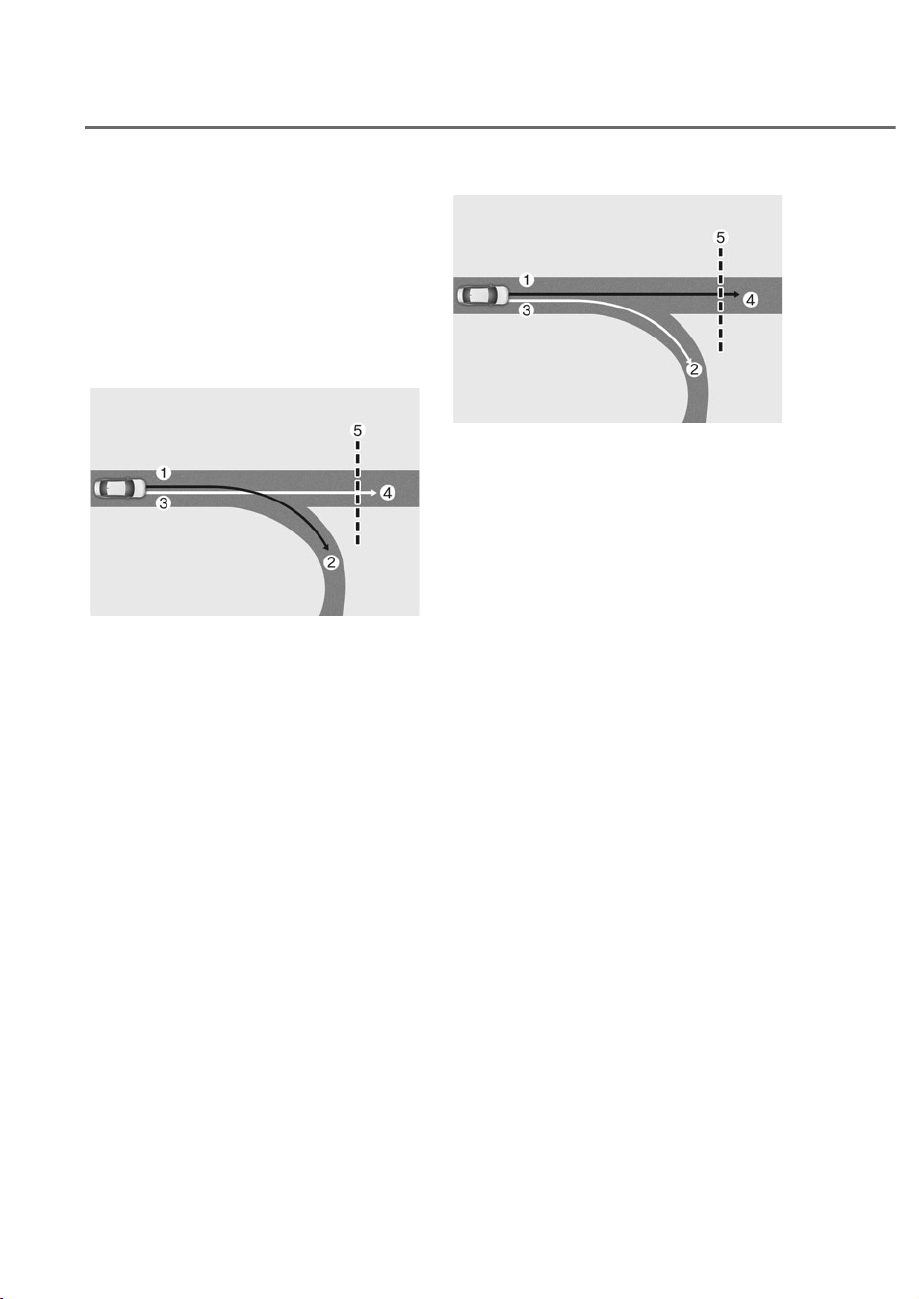
7-96
Driver Assistance System
• Driving on a road under construction
• Driving on a road that is controlled
• There is bad weather, such as heavy
rain, heavy snow, etc.
• Driving on a road that is sharply
curved
• Rear wheel steering system (if
equipped) is disabled
ORS071187L
ORS071187L
M: Set route,
N: Branch line,
O: Driving route,
P: Main road,
Q: Curved road section
• When there is a difference between
the navigation set route (branch line)
and the driving route (main road),
Highway Curve Zone Auto Slowdown
function may not operate until the
driving route is recognized as the
main road.
• When the vehicle's driving route
is recognized as the main road by
maintaining the main road instead
of the navigation set route, Highway
Curve Zone Auto Slowdown function
will operate. Depending on the
distance to the curve and the current
vehicle speed, vehicle deceleration
may not be sufficient or may
decelerate rapidly.
ORS071188L
ORS071188L
M: Set route,
N: Branch line,
O: Driving route,
P: Main road,
Q: Curved road section
• When there is a difference between
the navigation route (main road)
and the driving route (branch line),
Highway Curve Zone Auto Slowdown
function will operate based on the
curve information on the main road.
• When it is judged that you are driving
out of the route by entering the
highway interchange or junction,
Highway Curve Zone Auto Slowdown
function will not operate.

7-97
07
ORS071189L
ORS071189L
M: Driving route,
N: Branch line,
O: Curved road section,
P: Main road
• If there is no destination set on the
navigation, Highway Curve Zone Auto
Slowdown function will operate based
on the curve information on the main
road.
• Even if you depart from the main road,
Highway Curve Zone Auto Slowdown
function may temporarily operate
due to navigation information of the
highway curve section.
WARNING
• 1DYLJDWLRQEDVHG6PDUW&UXLVH
&RQWUROLVQRWDVXEVWLWXWHIRUVDIH
GULYLQJSUDFWLFHVEXWDFRQYHQLHQFH
IXQFWLRQ$OZD\VKDYH\RXUH\HVRQ
WKHURDGDQGLWLVWKHUHVSRQVLELOLW\
RIWKHGULYHUWRDYRLGYLRODWLQJWUDIILF
ODZV
• 7KHQDYLJDWLRQȂVVSHHGOLPLW
LQIRUPDWLRQPD\GLIIHUIURPWKH
actual speed limit information on the
URDG,WLVWKHGULYHUVUHVSRQVLELOLW\
to check the speed limit on the
DFWXDOGULYLQJURDGRUODQH
• 1DYLJDWLRQEDVHG6PDUW&UXLVH
&RQWUROZLOODXWRPDWLFDOO\EH
FDQFHOHGZKHQ\RXOHDYHWKH
KLJKZD\PDLQURDG$OZD\VSD\
DWWHQWLRQWRURDGDQGGULYLQJ
FRQGLWLRQVZKLOHGULYLQJ
• 1DYLJDWLRQEDVHG6PDUW&UXLVH
&RQWUROPD\QRWRSHUDWHGXHWRWKH
H[LVWHQFHRIOHDGLQJYHKLFOHVDQG
WKHGULYLQJFRQGLWLRQVRIWKHYHKLFOH
$OZD\VSD\DWWHQWLRQWRURDGDQG
GULYLQJFRQGLWLRQVZKLOHGULYLQJ
• :KHQ\RXDUHWRZLQJDWUDLOHURU
DQRWKHUYHKLFOHWXUQRII1DYLJDWLRQ
EDVHG6PDUW&UXLVH&RQWUROIRUVDIHW\
UHDVRQV
• $IWHU\RXSDVVWKURXJKDWROOJDWHRQ
DKLJKZD\1DYLJDWLRQEDVHG6PDUW
&UXLVH&RQWUROZLOORSHUDWHEDVHGRQ
WKHILUVWODQH,I\RXHQWHURQHRIWKH
RWKHUODQHV1DYLJDWLRQEDVHG6PDUW
Cruise Control might not operate
SURSHUO\
• 7KHYHKLFOHZLOODFFHOHUDWHLIWKH
GULYHUGHSUHVVHVWKHDFFHOHUDWRU
SHGDOZKLOH1DYLJDWLRQEDVHG6PDUW
&UXLVH&RQWUROLVRSHUDWLQJDQG
the function will not decelerate the
YHKLFOH+RZHYHULIWKHDFFHOHUDWRU
SHGDOLVGHSUHVVHGLQVXIILFLHQWO\WKH
YHKLFOHPD\GHFHOHUDWH
• ,IWKHGULYHUDFFHOHUDWHVDQG
releases the accelerator pedal while
1DYLJDWLRQEDVHG6PDUW&UXLVH
&RQWUROLVRSHUDWLQJWKHYHKLFOHPD\
QRWGHFHOHUDWHVXIILFLHQWO\RUPD\
UDSLGO\GHFHOHUDWHWRDVDIHVSHHG
• ,IWKHFXUYHLVWRRODUJHRUWRRVPDOO
1DYLJDWLRQEDVHG6PDUW&UXLVH
&RQWUROPD\QRWRSHUDWH

7-98
Driver Assistance System
Information
• A time gap could occur between the
navigation’s guidance and when
Navigation-based Smart ruise ontrol
operation starts and ends.
• The speed information on the cluster
and navigation may differ.
• Even if you are driving at a speed lower
than Smart ruise ontrol set speed,
acceleration may be limited by the
curve sections ahead.
• If Navigation-based Smart ruise
ontrol is operating while leaving the
main road to enter an interchange,
unction, rest area, etc., the function
may operate for a certain period of
time.
• Deceleration by Navigation-based
Smart ruise ontrol may feel it is not
sufficient due to road conditions such
as uneven road surfaces, narrow lanes,
etc.
Information
This device complies with Part 15 of the
F rules. peration is sub ect to the
following three conditions:
1. This device may not cause harmful
interference, and
2. This device must accept any
interference received, including
interference that may cause undesired
operation.
3. hanges or modifications not expressly
approved by the party responsible
for compliance could void the user’s
authority to operate the device.
Information
Radio frequency radiation exposure
information:
This equipment complies with F
radiation exposure limits set forth for an
uncontrolled environment.This equipment
should be installed and operated with
minimum distance of 8 in. (20 cm) between
the radiator (antenna) and your body.
This transmitter must not be co-located or
operating in con unction with any other
antenna or transmitter.
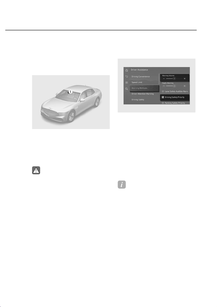
7-99
07
Lane Following Assist helps detect lane
markings and/or a vehicle ahead on the
road, and helps center your vehicle in the
lane.
Detecting sensor
ORS071001
ORS071001
M: Front view camera
The front view camera is used as a
detecting sensor to detect lane markings
and front vehicles.
Refer to the picture above for the
detailed location of the detecting sensor.
CAUTION
For more details on the precautions
RIWKHIURQWYLHZFDPHUDUHIHUWR
ȃ)RUZDUG&ROOLVLRQ$YRLGDQFH$VVLVW
)&$ȄVHFWLRQLQWKLVFKDSWHU
Lane Following Assist Settings
Warning methods
ORS073336N
ORS073336N
With the engine on, go to 'Driver
$VVLVWDQFHɌ:DUQLQJ0HWKRGVIURPWKH
Settings in the infotainment system to
select the following:
• Warning Volume: The warning volume
can be adjusted. If you turn off the
Warning Volume, for your safety, the
function may warn you with a low
volume.
• Driving Safety Priority: Your vehicle
lowers all other audio volumes when
the Driver Assistance system warning
sounds.
Information
• If you change the Warning Methods,
Warning Methods of other Driver
Assistance systems may change.
• Warning Method will maintain its last
setting even if the vehicle is restarted.
• The setting menu may not be available
for your vehicle depending on the
vehicle features and specifications.
/$1()2//2:,1*$66,67ʚ/)$ʛ
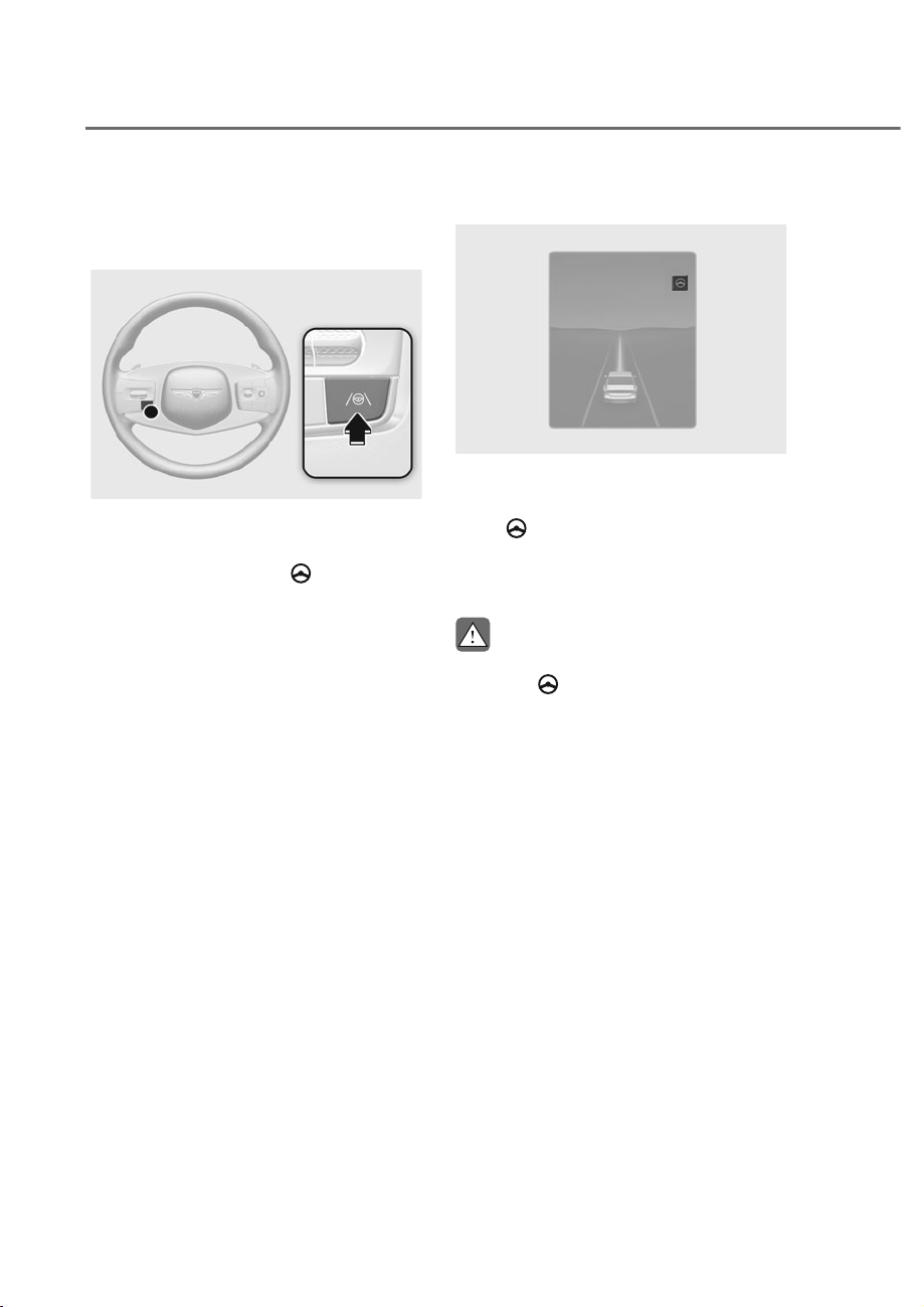
7-100
Driver Assistance System
Lane Following Assist Operation
Turning Lane Following Assist On/
Off
ORS071024
ORS071024
With the engine on, shortly press the
Lane Driving Assist button located on the
steering wheel to turn on Lane Following
Assist. The grey or green
indicator
light will illuminate on the cluster.
Press the button again to turn off the
function.
Lane Following Assist
ORS073134N
ORS073134N
If the vehicle ahead and/or both lane
markings are detected and your vehicle
speed is below 120 mph (200 km/h), the
green
indicator light illuminates on
the cluster, and Lane Following Assist
helps center the vehicle in the lane by
assisting the steering wheel.
CAUTION
:KHQWKHVWHHULQJZKHHOLVQRWDVVLVWHG
the white
LQGLFDWRUOLJKWEOLQNVDQG
FKDQJHWRJUH\
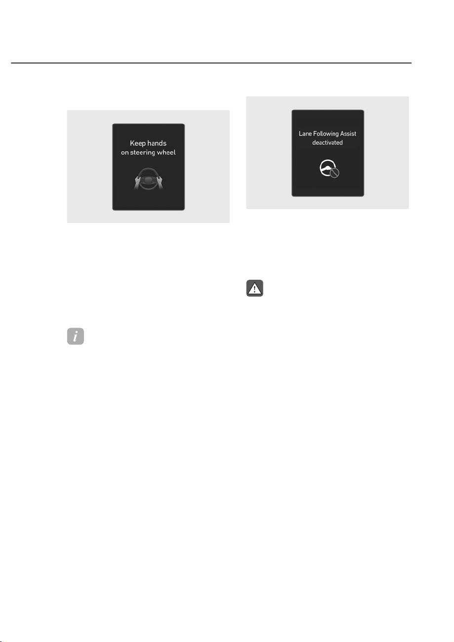
7-101
07
Hands-off warning
ORS071109L
ORS071109L
If the driver takes their hands off the
steering wheel for several seconds, the
‘Keep hands on steering wheel’ warning
message will appear and an audible
warning will sound.
First stage : Warning message
Second stage : Warning message (red
steering wheel) and
audible warning
Information
For more details on precautions of the
steering wheel grip sensor, refer to
"Steering Wheel Grip Sensor" section in
chapter 5.
ORS071219L
ORS071219L
If the driver still does not have their
hands on the steering wheel after the
hands-off warning, the ‘Lane Following
Assist deactivated’ warning message will
appear and Lane Following Assist will be
automatically canceled.
WARNING
• 7KHVWHHULQJZKHHOPD\QRWEH
assisted if the steering wheel is held
YHU\WLJKWRUWKHVWHHULQJZKHHOLV
VWHHUHGRYHUDFHUWDLQGHJUHH
• Lane Following Assist does not
RSHUDWHDWDOOWLPHV,WLVWKH
UHVSRQVLELOLW\RIWKHGULYHUWRVDIHO\
VWHHUWKHYHKLFOHDQGWRPDLQWDLQWKH
YHKLFOHLQLWVODQH
• The hands–off warning message
PD\DSSHDUODWHGHSHQGLQJRQURDG
FRQGLWLRQV$OZD\VKDYH\RXUKDQGV
RQWKHVWHHULQJZKHHOZKLOHGULYLQJ
• ,IWKHVWHHULQJZKHHOLVKHOGYHU\
OLJKWO\RUZHDUJORYHVWKHKDQGVǸ
RIIZDUQLQJPHVVDJHPD\DSSHDU
EHFDXVH/DQH)ROORZLQJ$VVLVWPD\
QRWUHFRJQL]HWKDWWKHGULYHUKDV
WKHLUKDQGVRQWKHVWHHULQJZKHHO
• ,I\RXDWWDFKREMHFWVWRWKHVWHHULQJ
ZKHHOWKHKDQGVRIIZDUQLQJPD\
QRWZRUNSURSHUO\
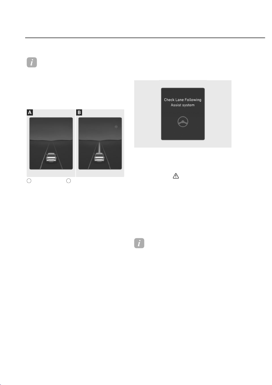
7-102
Driver Assistance System
Information
• For more details on instrument cluster
settings, refer to “L D display control”
section in chapter 4.
• When both lane markings are detected,
the lane lines on the cluster will change
from grey to white.
ORS072134N
ORS072134N
A
: Lane undetected,
B
: Lane detected
• The images and colors in the
instrument cluster may differ
depending on the cluster type or
theme selected from the settings
menu.
• If lane markings are not detected,
steering wheel control by Lane
Following Assist can be limited
depending on whether a vehicle is in
front or the driving conditions of the
vehicle.
• Even though the steering is assisted
by Lane Following Assist, the driver
may control the steering wheel.
• The steering wheel may feel heavier
or lighter when the steering wheel is
assisted by Lane Following Assist than
when it is not.
Lane Following Assist
0DOIXQFWLRQDQG/LPLWDWLRQV
Lane Following Assist malfunction
OJWEV071263L
OJWEV071263L
When Lane Following Assist is not
working properly, the ‘Check Lane
Following Assist system’ warning
message will appear for several seconds,
and the master (
) warning light will
illuminate on the instrument cluster. If
this occurs, have the vehicle inspected
by an authorized retailer of Genesis
Branded products.
Limitations of Lane Following Assist
For more details on Lane Following Assist
limitations, refer to “Lane Keeping Assist
(LKA)” section in this chapter.
Information
For more details on Lane Following Assist
precautions, refer to “Lane Keeping Assist
(LKA)” section in this chapter.
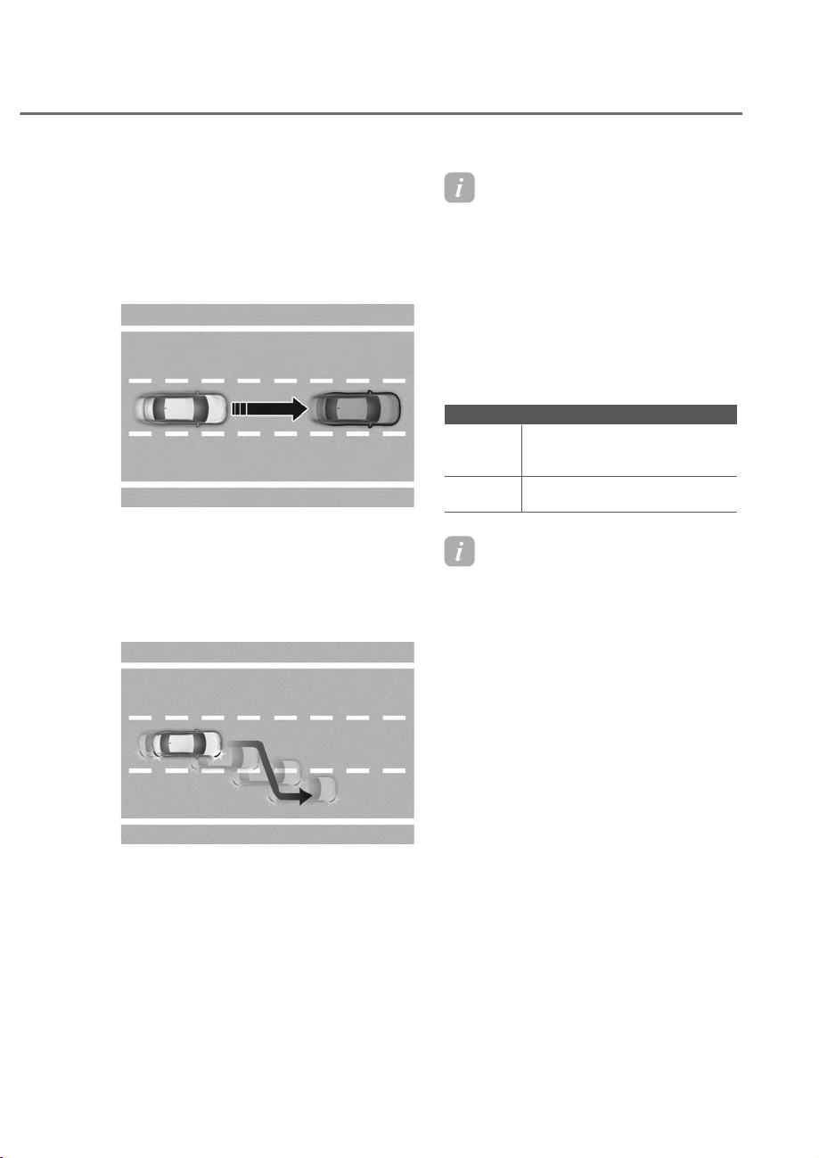
7-103
07
+,*+:$<'5,9,1*$66,67ʚ+'$ʛʚ,)(48,33('ʛ
+LJKZD\'ULYLQJ$VVLVW
Highway Driving Assist helps detect
lanes and vehicles ahead, helps maintain
the distance from the vehicle ahead and
the set speed, and helps center your
vehicle in the lane while driving on the
highway.
ORS071030
ORS071030
+LJKZD\/DQH&KDQJH$VVLVW
Highway Lane Change Assist function
helps change lanes to the direction
you operate the turn signal switch if
the function judges that lane change is
possible.
ORS071031
ORS071031
Information
• Highway Driving Assist is available
only on controlled access road of
certain highways.
à ontrolled access road indicates
roads with limited entrances and
exits that allow uninterrupted high
speed traffic flow. nly passenger
cars and motorcycles are allowed on
controlled access roads.
• Additional highways may be expanded
by future navigation updates.
$YDLODEOHKLJKZD\&RQWUROOHGDFFHVVURDG
USA
Select Interstate Highway and
U.S. (Federal) and State
Highways
Canada
Select Provincial and
Territorial Highways
Information
Highway Driving Assist operates on main
roads of highways, and does not operate
on interchanges or unctions.
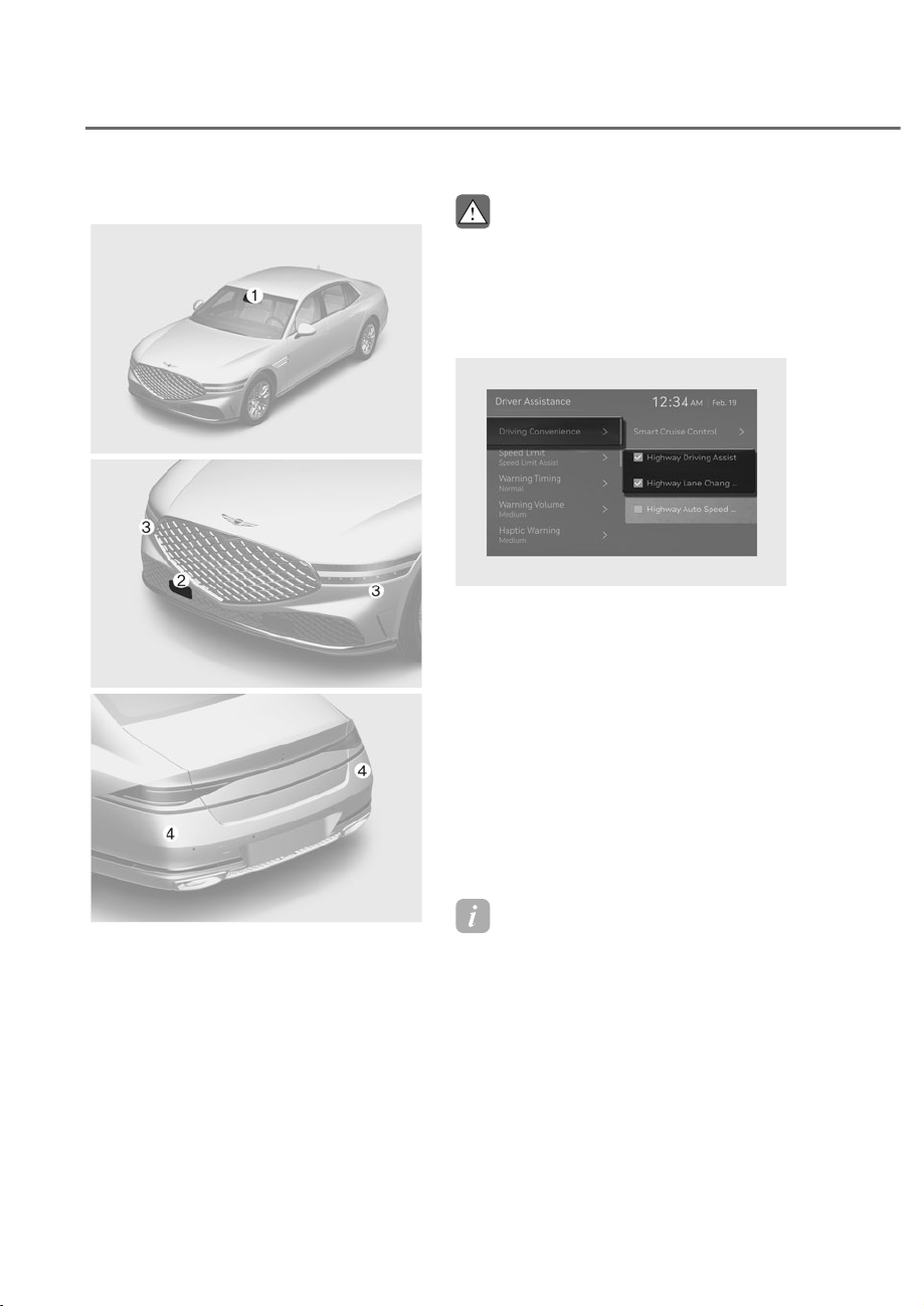
7-104
Driver Assistance System
Detecting sensor
ORS071001
ORS071001
ORS072292
ORS072292
ORS072003N
ORS072003N
M: Front view camera,
N: Front radar,
O: Front corner radar,
P: Rear corner radar
Refer to the picture above for the
detailed location of the detecting
sensors.
CAUTION
For more details on the precautions of
WKHGHWHFWLQJVHQVRUVUHIHUWRȃ)RUZDUG
&ROOLVLRQ$YRLGDQFH$VVLVW)&$Ȅ
VHFWLRQLQWKLVFKDSWHU
+LJKZD\'ULYLQJ$VVLVW6HWWLQJV
ORS071272L
ORS071272L
With the engine on, select or deselect
ȁ'ULYHU$VVLVWDQFHɌ'ULYLQJ&RQYHQLHQFHȂ
from the Settings menu to set whether to
use each function.
Highway Driving Assist
If ‘Highway Driving Assist’ is selected, it
helps maintain distance from the vehicle
ahead, maintain the set speed, and helps
center the vehicle in the lane.
Highway Lane Change Assist
If ‘Highway Lane Change Assist’ is
selected, it helps the driver change lanes.
Information
• When ‘Highway Driving Assist’ is
deselected, the setting for ‘Highway
Lane hange Assist’ cannot be
changed.
• If there is a problem with the functions,
the settings cannot be changed. Have
the vehicle inspected by an authorized
retailer of Genesis Branded products.
• If the engine is restarted, the functions
will maintain the last setting.
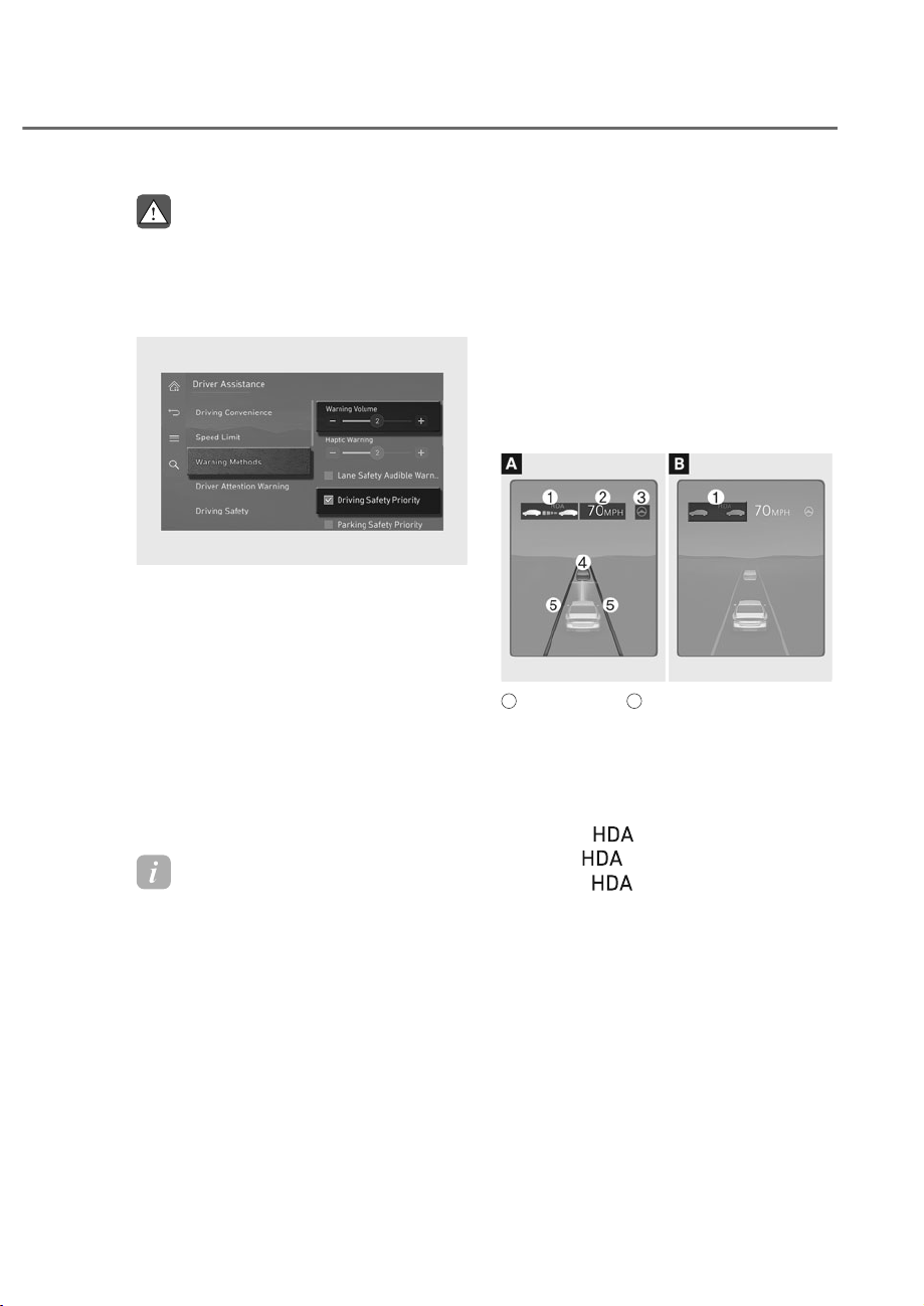
7-105
07
WARNING
)RU\RXUVDIHW\RQO\FKDQJHWKH
6HWWLQJVDIWHUSDUNLQJWKHYHKLFOHDWD
VDIHORFDWLRQ
Warning methods
ORS073336N
ORS073336N
With the engine on, go to 'Driver
$VVLVWDQFHɌ:DUQLQJ0HWKRGVIURPWKH
Settings in the infotainment system to
select the following:
• Warning Volume: The warning volume
can be adjusted. If you turn off the
Warning Volume, for your safety, the
function may warn you with a low
volume.
• Driving Safety Priority: Your vehicle
lowers all other audio volumes when
the Driver Assistance system warning
sounds.
Information
• If you change the Warning Methods,
Warning Methods of other Driver
Assistance systems may change.
• Warning Method will maintain its last
setting even if the vehicle is restarted.
• The setting menu may not be available
for your vehicle depending on the
vehicle features and specifications.
+LJKZD\'ULYLQJ$VVLVW
Operation
Highway Driving Assist
Displaying operating status
You can see the status of the Highway
Driving Assist operation in the Driving
Assist view on the cluster. Refer to “View
Modes” section in chapter 4.
Highway Driving Assist will be displayed
as below depending on the status of the
function.
ORS072092N
ORS072092N
A
: Operating state,
B
: Standby state
(1) Highway Driving Assist indicator,
whether there is a vehicle ahead
and the selected distance level are
displayed.
à Highway Driving Assist indicator
- Green
: Operating state
-Grey
: Standby state
- White
blink: Accelerator
depressed state
(2) Set speed
(3) Lane Following Assist indicator
(4) Whether there is a vehicle ahead and
the selected headway
(5) Whether the lane is detected or not
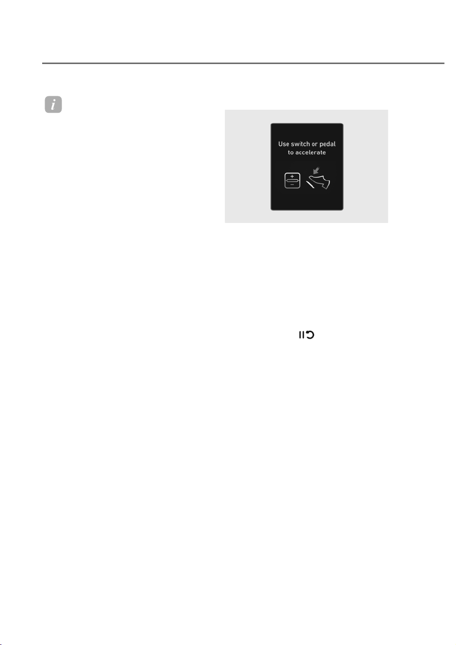
7-106
Driver Assistance System
Information
• For more details on the display refer
to “Smart ruise ontrol (S )” and
“Lane Following Assist (LFA)” sections
in this chapter.
• The images and colors in the
instrument cluster may differ
depending on the cluster type or theme
selected from the settings menu.
Highway Driving Assist operation
Highway Driving Assist operates when:
• Driving on the main road of highways,
and turning on Highway Driving Assist
by pressing the Driving Assist button.
• Entering the main road of highways
while Lane Following assist and Smart
Cruise Control are operating
Restarting after stopping
OJWEV071266L
OJWEV071266L
When Highway Driving Assist is
operating, your vehicle will stop if the
detected vehicle ahead of you stops.
Also, if the detected vehicle ahead of you
starts moving within 30 seconds after
the stop, your vehicle will start as well.
In addition, after the vehicle has stopped
and 30 seconds have passed, the ‘Use
switch or pedal to accelerate’ message
will appear on the cluster. Depress
the accelerator pedal or operate the +
switch, - switch or
switch to start
driving.
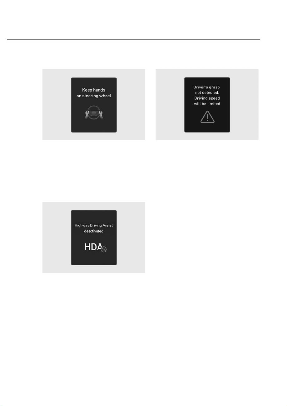
7-107
07
Hands-off warning
ORS071109L
ORS071109L
If the driver takes their hands off the
steering wheel for several seconds, the
‘Keep hands on steering wheel’ warning
message will appear and an audible
warning will sound.
First stage : Warning message
Second stage : Warning message (red
steering wheel) and
audible warning
ORS071123L
ORS071123L
If the driver still does not have their
hands on the steering wheel after the
hands-off warning, ‘Highway Driving
Assist deactivated’ warning message will
appear and Highway Driving Assist and
Lane Change Assist will be automatically
canceled.
Driving speed limit
OJK070103L
OJK070103L
When Highway Driving Assist is canceled
by the hands-off warning, The driving
speed will be limited.
While Driving Speed Limit function
is operating, the ‘Driver’s grasp not
detected. Driving speed will be limited’
warning message will appear on the
cluster, and an audible warning will
sound continuously.
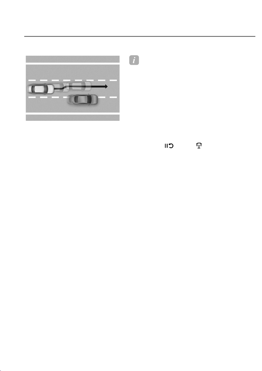
7-108
Driver Assistance System
ORS071076
ORS071076
Driving to one side within lane
When vehicle speed is above 40 mph (60
km/h), if a detected vehicle around you is
driving at a close distance, your vehicle
will control steering in the opposite
direction of the vehicle to assist in safe
driving. If there a detected vehicle in
both sides of the lane that are driving
close to you, the function will not veer to
the opposite side of the lane.
Highway Driving Assist standby
When Smart Cruise Control is
temporarily canceled while Highway
Driving Assist is operating, Highway
Driving Assist will be in the standby state.
At this time, Lane Following Assist will
operate properly.
Information
• Driving Speed Limit helps you drive
below 40 mph (60 km/h). At this time,
the vehicle decelerates due to the
vehicle ahead. After the vehicle has
decelerated, it cannot automatically
accelerate.
• Driving Speed Limit will cancel in the
following circumstances:
- When the driver grabs the steering
wheel again
- When the driver turns on Lane
Following Assist by pressing the Lane
Driving Assist button
- When , -,
switch or button is
operated, or the accelerator pedal or
the brake pedal is depressed
Highway Lane Change Assist
Displaying operating status
You can see the status of the Highway Lane
Change Assist operation in the Driving
Assist view on the cluster. Refer to “View
Modes” section in chapter 4.
Highway Lane Change Assist function
will be displayed as below depending on
the status of the function.

7-109
07
ORS072093N
ORS072093N
A
: Ready/Operating,
B
: Standby/Canceled
(1) Highway Lane Change Assist
indicator
• Green on : Ready state
• Green blink : Operating state
• Grey on : Standby state
• White blink : Canceled state
(display only a certain time)
(2) Green lane line
The lane line is displayed same as
the Highway Lane Change Assist
indicator (1). However, if the function
is on standby, it displays whether the
lane line is detected.
(3) Green arrow and shade
The green arrow is displayed when a
certain amount of time has passed
after the function has started
operating, and until the lane change
has completed.
(4) Message
• Message is displayed when the
function does not operate even
though the turn signal is used.
• Message is displayed when
the function is canceled while
operating.
To turn on Highway Lane hange Assist
Highway Lane Change Assist function
will turn on when the following
conditions are satisfied.
• The Driving Assist button or Lane
Driving Assist button is used to turn
on Highway Driving Assist.
Highway Lane hange Assist ready to
operate
While Highway Lane Change Assist
function is on, the function will be
ready to operate when all the following
conditions are satisfied:
• Highway Driving Assist is operating
• Lane Following Assist is operating
• A vehicle in the rear area of your
vehicle is detected more than once
after the engine is turned on
• Your vehicle speed is above 40 mph
(60 km/h)
• Hands-off warning is not displayed on
the cluster
• Hazard warning flasher is off
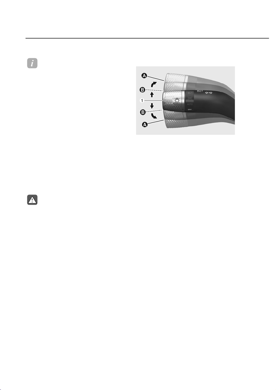
7-110
Driver Assistance System
Information
• While Lane hange Assist function
is turned on (indicator on), Lane
Following Assist will not cancel even
if the turn signal indicator or hazard
warning flasher is operating.
• Lane hange Assist function turns
off automatically when driven in the
following road conditions:
- ne driving lane
- A road with a intersection or
crosswalk ahead
- A road with no structure, such as a
medium strip, guardrails, etc.
- There is a pedestrian or cyclist on the
road ahead
• When the function is in the ready state,
and vehicle speed is below 35 mph (55
km/h), the function will change to the
standby state.
WARNING
:KHQ+LJKZD\/DQH&KDQJH$VVLVW
IXQFWLRQWXUQVRIIZKLOHRSHUDWLQJ
VWHHULQJDVVLVWZLOOEHWHPSRUDULO\
FDQFHOHG$OZD\VEHFDXWLRXVZKLOH
GULYLQJ
Highway Lane hange Assist operating
ORS071269
ORS071269
M: Center
Highway Lane Change Assist function
will operate, when you push the turn
signal lever up or down to the A or B
position while the function is in the ready
state (indicator is green), and all of the
following conditions are satisfied:
• The driver has his/her hand on the
steering wheel
• There is no collision risk in the
direction of lane change
• There is a single dotted lane line in the
direction of lane change
• There are no Forward Collision-
Avoidance Assist and Blind Spot
Collision-Avoidance Assist warnings
• The vehicle is driven in the middle of
the lane (should not be driving close
to one side of the lane)
• The road you are driving on, or the
road you are about to change lane is a
road that the function can operate

7-111
07
Information
• Highway Lane hange Assist operates
when the turn signal lever is positioned
at A. If the turn signal lever is released
to the center M before stepping on the
lane, Highway Lane hange Assist
cancels. If the turn signal lever is
released to the center M after stepping
on the lane, Highway Lane hange
Assist changes the lane and turns off
the turn signal after lane change is
complete.
• When the turn signal lever is placed at
B position for a certain period of time,
the green arrow will appear. At this
time, even when the lever is released
and returns to it’s original position M
lane change will still be assisted.
• While lane change is being made by the
function, the turn signal indicator will
blink even when the turn signal lever is
not held, and the turn signal indicator
will turn off when lane change is
complete.
Highway Lane hange Assist standby
Highway Lane Change Assist function
will be in the standby state when one of
the ready state condition is not satisfied,
or when entering or driving on one of the
following roads:
• Road within a certain distance from
the tollgate on the main road of the
highway
• The road ahead ends without an
interchange or junction
• Road with sharp curves
• Road with narrow lanes
• Road that is under construction
Highway Lane hange Assist cancel
The function will be canceled when:
• The turn signal lever is turned on in
the opposite direction of lane change
• The steering wheel is steered sharply
WARNING
• :KLOHWKHIXQFWLRQLVRSHUDWLQJWKH
function will cancel if one of the
following occurs:
- +LJKZD\'ULYLQJ$VVLVWLVWXUQHG
off
- Lane Following Assist or Smart
Cruise Control is turned off or
WHPSRUDULO\FDQFHOHG
- +DQGVRIIZDUQLQJPHVVDJHLV
GLVSOD\HGRQWKHFOXVWHU
- 7KHKD]DUGZDUQLQJIODVKHULV
turned on
- )RUZDUG&ROOLVLRQ$YRLGDQFH
Assist or Blind-Spot Collision
$YRLGDQFH$VVLVWZDUQLQJPHVVDJH
LVGLVSOD\HG
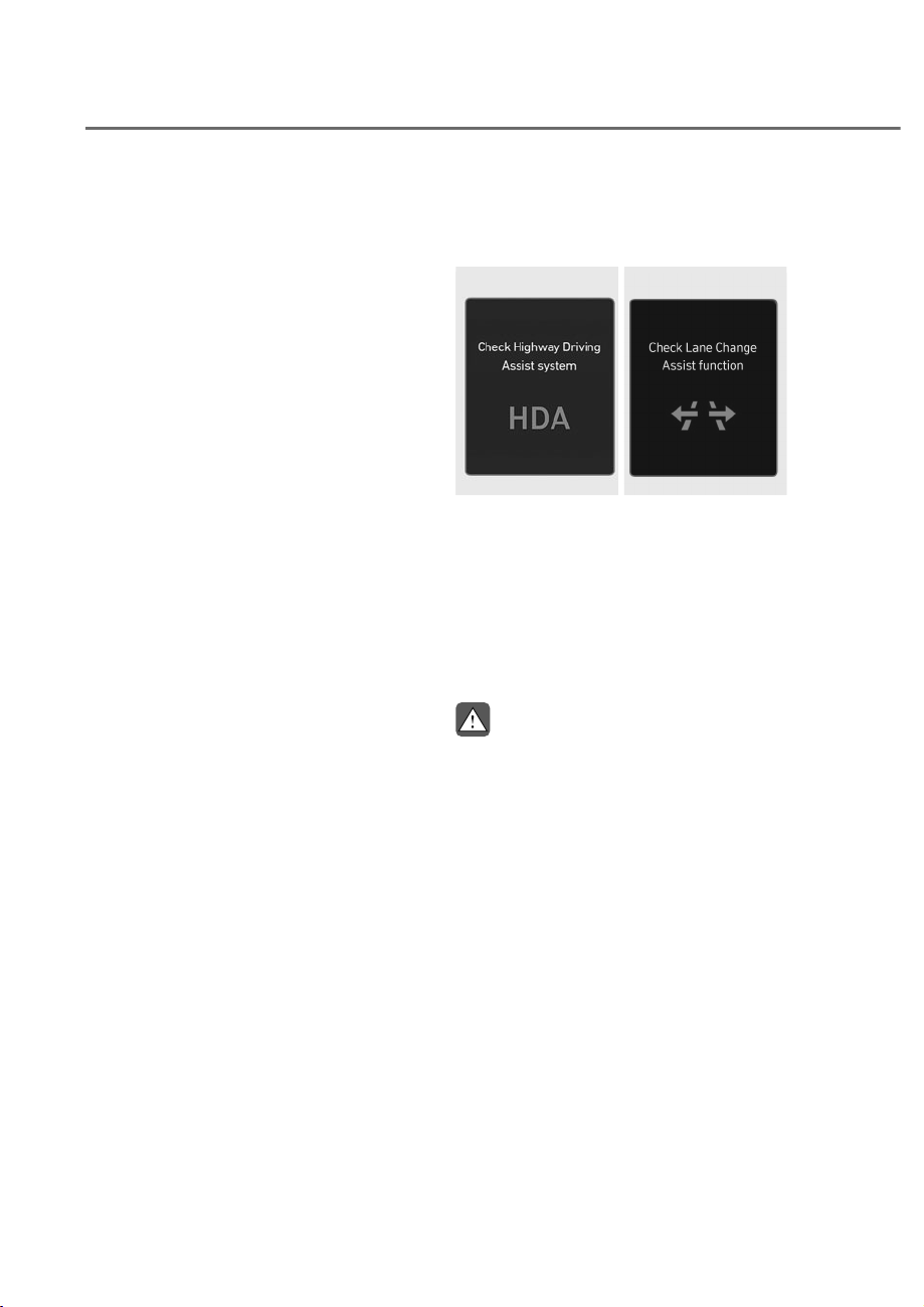
7-112
Driver Assistance System
- 3RVVLEOHFROOLVLRQLVGHWHFWHGLQWKH
QH[WODQHHYHQWKRXJKWKHUHDUH
QR)RUZDUG&ROOLVLRQ$YRLGDQFH
Assist and Blind-Spot Collision
$YRLGDQFH$VVLVWZDUQLQJ
- (QWHULQJDURDGXQGHUFRQVWUXFWLRQ
- The target lane to make a lane
change disappears
- 7KHUHLVDSUREOHPZLWKWXUQVLJQDO
lamps
- +LJKZD\/DQH&KDQJH$VVLVW
function is off (The function turns
off when the function is turned off
IURPWKHVHWWLQJVPHQXZKHQWKH
URDGFKDQJHVWRDRQHZD\URDG
when there is an intersection or
FURVVZDONDKHDGZKHQ\RXHQWHU
DURDGZLWKQRVWUXFWXUHVXFKDV
DPHGLXPVWULSJXDUGUDLOHWFRU
when there is a pedestrian or
F\FOLVWRQWKHGULYLQJODQH
- <RXUYHKLFOHVSHHGLVEHORZȺȼ
PSKȼȼNPK
• :KLOHWKHIXQFWLRQLVRSHUDWLQJ
ZKHQWKHIXQFWLRQLVFDQFHOHG
GHSHQGLQJRQWKHGULYLQJFRQGLWLRQV
WKHYHKLFOHPD\GULYHWRWKHPLGGOH
RIWKHGULYLQJODQHRUVWHHULQJDVVLVW
PD\VWRS$OZD\VSD\DWWHQWLRQWR
URDGDQGGULYLQJFRQGLWLRQVZKLOH
GULYLQJ
• 7KHIXQFWLRQPD\QRWRSHUDWH
SURSHUO\RQURDGVZLWKSHGHVWULDQV
RUF\FOLVWVVXFKDVDQLQWHUVHFWLRQ
RUFURVVZDON$OZD\VSD\DWWHQWLRQ
WRURDGDQGGULYLQJFRQGLWLRQVZKLOH
GULYLQJ
+LJKZD\'ULYLQJ$VVLVW
0DOIXQFWLRQDQG/LPLWDWLRQV
Highway Driving Assist malfunction
ORS071218L
ORS071218L
OJWEV071272L
OJWEV071272L
When Highway Driving Assist or Highway
Lane Change function is not working
properly, the ‘Check Highway Driving
Assist system’ warning message will
appear, and the warning light will
illuminate on the instrument cluster.
Have the vehicle inspected by an
authorized retailer of Genesis Branded
products.
WARNING
• 7KHGULYHULVUHVSRQVLEOHIRU
FRQWUROOLQJWKHYHKLFOHIRUVDIH
GULYLQJ
• $OZD\VKDYH\RXUKDQGVRQWKH
VWHHULQJZKHHOZKLOHGULYLQJ
• +LJKZD\'ULYLQJ$VVLVWLVD
supplemental function that assists
WKHGULYHULQGULYLQJWKHYHKLFOH
and is not a complete autonomous
GULYLQJV\VWHP$OZD\VFKHFNURDG
FRQGLWLRQVDQGLIQHFHVVDU\WDNH
DSSURSULDWHDFWLRQVWRGULYHVDIHO\
• $OZD\VKDYH\RXUH\HVRQWKHURDG
DQGLWLVWKHUHVSRQVLELOLW\RIWKH
GULYHUWRDYRLGYLRODWLQJWUDIILFODZV
7KHYHKLFOHPDQXIDFWXUHULVQRW
UHVSRQVLEOHIRUDQ\WUDIILFYLRODWLRQ
RUDFFLGHQWVFDXVHGE\WKHGULYHU

7-113
07
• +LJKZD\'ULYLQJ$VVLVWPD\QRW
EHDEOHWRUHFRJQL]HDOOWUDIILF
VLWXDWLRQV+LJKZD\'ULYLQJ$VVLVW
PD\QRWGHWHFWSRVVLEOHFROOLVLRQV
GXHWROLPLWDWLRQVRIWKHIXQFWLRQ
$OZD\VEHDZDUHRIWKHOLPLWDWLRQV
RIWKHIXQFWLRQ2EVWDFOHVVXFKDV
YHKLFOHVPRWRUF\FOHVELF\FOHV
SHGHVWULDQVRUXQVSHFLILHGREMHFWV
RUVWUXFWXUHVVXFKDVJXDUGUDLOV
WROOJDWHHWFWKDWPD\FROOLGHZLWK
WKHYHKLFOHPD\QRWEHGHWHFWHG
• +LJKZD\'ULYLQJ$VVLVWZLOOWXUQRII
DXWRPDWLFDOO\XQGHUWKHIROORZLQJ
situations:
- 'ULYLQJRQURDGVWKDW+LJKZD\
'ULYLQJ$VVLVWGRHVQRWRSHUDWH
VXFKDVDUHVWDUHDLQWHUVHFWLRQ
MXQFWLRQHWF
- 7KHQDYLJDWLRQGRHVQRWRSHUDWH
SURSHUO\VXFKDVZKHQWKH
QDYLJDWLRQLVEHLQJXSGDWHGRU
restarted
• +LJKZD\'ULYLQJ$VVLVWPD\
LQDGYHUWHQWO\RSHUDWHRUWXUQRII
depending on road conditions
QDYLJDWLRQLQIRUPDWLRQDQG
VXUURXQGLQJV
• /DQH)ROORZLQJ$VVLVWIXQFWLRQPD\
EHWHPSRUDULO\GLVDEOHGZKHQWKH
IURQWYLHZFDPHUDFDQQRWGHWHFW
ODQHVSURSHUO\RUWKHKDQGVRII
ZDUQLQJLVRQ
• <RXPD\QRWKHDUWKHZDUQLQJVRXQG
RI+LJKZD\'ULYLQJ$VVLVWLIWKH
VXUURXQGLQJLVQRLV\
• ,IWKHYHKLFOHLVGULYHQDWKLJKVSHHG
DERYHDFHUWDLQVSHHGDWDFXUYH
\RXUYHKLFOHPD\GULYHWRRQHVLGHRU
PD\GHSDUWIURPWKHGULYLQJODQH
• :KHQ\RXDUHWRZLQJDWUDLOHURU
DQRWKHUYHKLFOHWXUQRII+LJKZD\
'ULYLQJ$VVLVWIRUVDIHW\UHDVRQV
• The hands–off warning message
PD\DSSHDUHDUO\RUODWHGHSHQGLQJ
on how the steering wheel is held or
URDGFRQGLWLRQV$OZD\VKDYH\RXU
hands on the steering wheel while
GULYLQJ
• )RU\RXUVDIHW\UHDGWKHRZQHUV
PDQXDOEHIRUHXVLQJ+LJKZD\
'ULYLQJ$VVLVW
• +LJKZD\'ULYLQJ$VVLVWZLOOQRW
RSHUDWHLPPHGLDWHO\DIWHUWKH
YHKLFOHLVVWDUWHGRUZKHQWKH
GHWHFWLQJVHQVRUVRUQDYLJDWLRQLV
EHLQJLQLWLDOL]HG

7-114
Driver Assistance System
Limitations of Highway Driving
Assist
Highway Driving Assist and Highway
Lane Change function may not operate
properly, or it may not operate under the
following circumstances:
• The map information and the
actual road is different because the
navigation is not updated
• The map information and the actual
road is different because of real-time
GPS data or map information error
• The infotainment system is overloaded
by simultaneously performing
functions such as route search, video
playback, voice recognition, etc.
• GPS signals are blocked in areas such
as a tunnel
• The driver goes off course or the
route to the destination is changed or
canceled by resetting the navigation
• The vehicle enters a service station or
rest area
• Android Auto or Car Play is operating
• The navigation cannot detect the
current vehicle position (for example,
elevated roads including overpass
adjacent to general roads or nearby
roads exist in a parallel way)
• White single dotted lane line or road
edge cannot be detected
• The road is temporarily controlled due
to construction, etc.
• There is no structure, such as a
medium strip, guardrails, etc., on the
road
• There is a changeable lane in the
direction of lane change
• Rear wheel steering system (if
equipped) is disabled
Information
For more details on the limitations of
the front view camera, front radar, front
corner radar and rear corner radar, refer
to “Forward ollision-Avoidance Assist
(F A)” section in this chapter.
Information
This device complies with Part 15 of the
F rules. peration is sub ect to the
following three conditions:
1. This device may not cause harmful
interference, and
2. This device must accept any
interference received, including
interference that may cause undesired
operation.
3. hanges or modifications not expressly
approved by the party responsible
for compliance could void the user’s
authority to operate the device.
Information
Radio frequency radiation exposure
information:
This equipment complies with F
radiation exposure limits set forth for an
uncontrolled environment.This equipment
should be installed and operated with
minimum distance of 8 in. (20 cm) between
the radiator (antenna) and your body.
This transmitter must not be co-located or
operating in con unction with any other
antenna or transmitter.
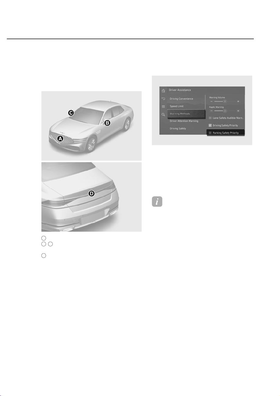
7-115
07
Surround View Monitor can assist in
parking by allowing the driver to see
around the vehicle.
Detecting sensor
ORS071140
ORS071140
ORS071141
ORS071141
A
: Wide-front view camera,
B
,
C
: Wide-side view camera
(Below the side view mirror),
D
: Wide-rear view camera
Refer to the picture above for the
detailed location of the detecting
sensors.
6XUURXQG9LHZ0RQLWRU6HWWLQJV
Warning methods
ORS073339N
ORS073339N
With the engine on, go to 'Driver
$VVLVWDQFHɌ:DUQLQJ0HWKRGVIURPWKH
Settings in the infotainment system to
select the following:
• Parking Safety Priority: Your vehicle
lowers all other audio volumes when
Surround View Monitor is operating.
Information
• If you change the Warning Methods,
Warning Methods of other Driver
Assistance systems may change.
• Warning Method will maintain its last
setting even if the vehicle is restarted.
• The setting menu may not be available
for your vehicle depending on the
vehicle features and specifications.
6855281'9,(:021,725ʚ690ʛ

7-116
Driver Assistance System
Camera settings
ORS072257N
ORS072257N
• You can change Surround View
Monitor ‘Display Contents’ or ‘Display
Settings’ by touching the setup icon
(
) on the screen while Surround
View Monitor is operating, or selecting
ȁ'ULYHU$VVLVWDQFHɌ3DUNLQJ6DIHW\Ɍ
Camera Settings’ from the Settings
menu while the vehicle is on.
• In the Display Contents, you can
change settings for ‘Top View Parking
Guide Lines’, ‘Rear View Parking Guide
Lines’ and ‘Parking Distance Warning’.
Top View Parking Guide
When the ‘Top View Parking Guide
Lines’ is selected, parking guide lines
is displayed on the right side of the
Surround View Monitor screen.
Information
The horizontal guideline shows the
distance of 1.6 ft (0.5 m) and 6.6 ft. (2 m)
from the vehicle.
Rear View Parking Guide
When the ‘Rear View Parking Guide
Lines’ is selected, parking Guide Lines is
displayed in the rear view.
Information
The horizontal guideline shows the
distance of 1.6 ft. (0.5 m), 3.3 ft. (1 m) and
7.6 ft. (2.3 m) from the vehicle.
Parking Distance Warning
When the ‘Parking Distance Warning’
is selected, parking distance warning
is displayed on the right side of the
Surround View Monitor screen.
• The image will be displayed only when
Parking Distance Warning is warning
the driver.
Surround View Monitor Auto On
With the engine on, select ‘Driver
$VVLVWDQFHɌ3DUNLQJ6DIHW\Ɍ6XUURXQG
View Monitor Auto On’ from the Settings
menu to use the function.
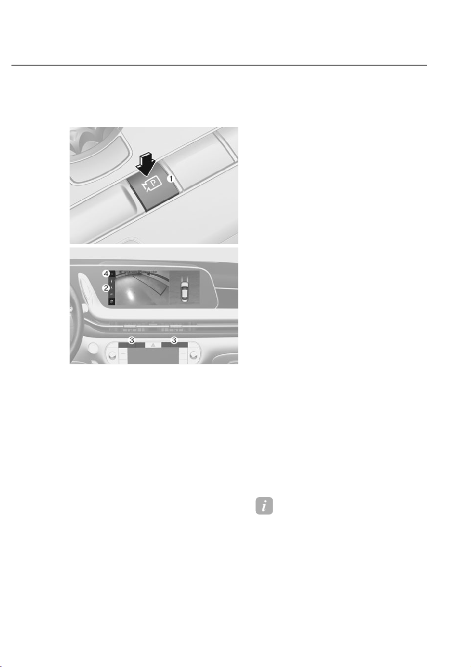
7-117
07
6XUURXQG9LHZ0RQLWRU
Operation
ORS071018
ORS071018
ORS072246N
ORS072246N
Press the Parking/View button M to turn
on Surround View Monitor.
Press the button again to turn off the
function.
Front View
The front image is displayed on the
screen when the gear is in N (Neutral) or
D (Drive) to assist in parking. Using the
view button N you may select top view,
front view, side view and 3D view.
Front iew while parking
The front view while parking function will
turn on under the following conditions:
• The gear is in N (Neutral) or D (Drive),
and vehicle speed is 6 mph (10 km/h)
or less.
• The Parking/View button M is pressed,
while the gear is in N (Neutral) or D
(Drive), and vehicle speed is 6 mph (10
km/h) or less.
• Surround View Monitor Auto On
function will operate when the
following conditions are satisfied:
- :LWKC'ULYHU$VVLVWDQFHɌ3DUNLQJ
6DIHW\Ɍ6XUURXQG9LHZ0RQLWRU
Auto On' selected from the Settings
menu, the front view while parking
is displayed.
The front view function will turn off
under the following conditions:
• The gear is shifted to P (Park) or R
(Reverse).
• The Parking/View button M or the
infotainment system button O is
pressed.
• Vehicle speed is above 6 mph (10
km/h).
• The Home button P is pressed.
Information
When the front view while parking is
turned on, the previous view mode will be
displayed.

7-118
Driver Assistance System
Rear view
The rear image is displayed on the screen
when the gear is in P (Park) to assist in
parking. Using the view button N you
may select top view, front view, side view
and 3D view.
Rear iew while parking
The rear view while parking function will
turn on under the following conditions:
• The Parking/View button M is
pressed, while the gear is in P (Park),
N (Neutral) or D( Drive), and vehicle
speed is 6 mph (10 km/h) or less.
• The gear is shifted to R (Reverse)
• The gear is shifted from R (Reverse) to
N (Neutral) or D (Drive)
When the gear is in P (Park), N (Neutral)
or D (Drive), the rear view function will
turn off under the following conditions:
• The gear is shifted to P (Park).
• The Parking/View button M or the
infotainment system button O is
pressed.
• The Home button P is pressed.
• The vehicle speed is above 6 mph (10
km/h).
When the gear is in R (Reverse), the rear
view function will turn off under the
following conditions:
• The gear is shifted to P (Park)
Information
• When the rear view turn on while the
gear is in P (Park), N (Neutral) or D
(Drive), the previous view mode will be
displayed.
• When the gear is in R (Reverse), the
rear view does not turn off.
3D view
The 3D view shows the image around the
vehicle from various angles.
You can change angles by tapping the
screen. Press the 3D View button again
to return to the initial angle.
3D view will turn on when the 3D view
is selected among the view buttons N
under the following conditions:
• The gear is in P (Park), N (Neutral) or D
(Drive) when vehicle speed is below 6
mph (10 km/h).
• The Surround View Monitor is turned
on when the gear is in R (Reverse).
When the gear is in P (Park), N (Neutral)
or D (Drive), 3D view will turn off under
the following conditions:
• The gear is shifted to P (Park).
• The Parking/View button M is pressed.
• The infotainment system button O is
pressed.
• The Home button P is pressed.
• Vehicle speed is above 6 mph (10
km/h).
Information
3D view does not display guidelines.

7-119
07
6XUURXQG9LHZ0RQLWRU
0DOIXQFWLRQDQG/LPLWDWLRQV
Surround View Monitor malfunction
When Surround View Monitor is not
working properly, or the screen flickers,
or the camera image does not display
properly, have the vehicle inspected by
an authorized retailer of Genesis Branded
products.
Limitations of Surround View
Monitor
• When the vehicle is stopped for a long
time in winter or when the vehicle is
parked in an indoor parking lot, the
exhaust fumes may temporarily blur
the image.
• The screen may be displayed
abnormally, and an icon will appear at
the top left side of the screen under
the following circumstances:
- The trunk is opened
- The driver or front passenger door
is opened
- The side view mirror is folded
WARNING
• $/:$<6ORRNDURXQG\RXUYHKLFOH
WRPDNHVXUHWKHUHDUHQRREMHFWV
RUREVWDFOHVEHIRUHPRYLQJWKH
YHKLFOH:KDW\RXVHHRQWKHVFUHHQ
PD\GLIIHUIURPWKHDFWXDOYHKLFOHȂV
ORFDWLRQ
• 7KHLPDJHVKRZQRQWKHVFUHHQPD\
differ from the actual distance of the
REMHFW0DNHVXUHWRGLUHFWO\FKHFN
WKHYHKLFOHVVXUURXQGLQJVIRUVDIHW\
• 6XUURXQG9LHZ0RQLWRULVGHVLJQHG
WREHXVHGRQDIODWVXUIDFH
7KHUHIRUHLIXVHGRQURDGVZLWK
GLIIHUHQWKHLJKWVVXFKDVFXUEV
DQGVSHHGEXPSVWKHLPDJHLQWKH
VFUHHQP\QRWORRNFRUUHFW
• $OZD\VNHHSWKHFDPHUDOHQVFOHDQ
,IWKHOHQVLVFRYHUHGZLWKIRUHLJQ
PDWHULDOLWPD\DGYHUVHO\DIIHFW
camera performance and Surround
9LHZ0RQLWRUPD\QRWRSHUDWH
SURSHUO\+RZHYHUGRQRWXVH
FKHPLFDOVROYHQWVVXFKDVVWURQJ
detergents containing high alkaline
RUYRODWLOHRUJDQLFVROYHQWVJDVROLQH
DFHWRQHHWF7KLVPD\GDPDJHWKH
FDPHUDOHQV
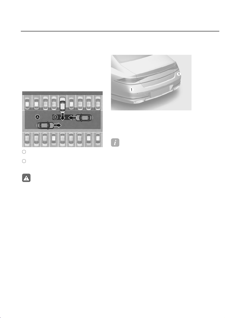
7-120
Driver Assistance System
Rear Cross-Traffic Collision-Avoidance
Assist is designed to help detect vehicles
approaching from the left and right side
while your vehicle is reversing. When a
vehicle is detected, the system will warn
the driver that a collision is imminent
with a visual and audible warning. The
system can also provide braking assist to
help prevent a collision.
ORS071085
ORS071085
A
: Rear Cross-Traffic Collision Warning operating
range,
B
: Rear Cross-Traffic Collision-Avoidance Assist
operating range
CAUTION
:DUQLQJWLPLQJPD\YDU\GHSHQGLQJRQ
WKHVSHHGRIWKHDSSURDFKLQJYHKLFOH
Detecting sensor
ORS072005N
ORS072005N
M: Rear corner radar
Refer to the picture above for the
detailed location of the detecting
sensors.
Information
For more details on the precautions of the
rear corner radar, refer to “Blind-Spot
ollision-Avoidance Assist (B A)” section
in this chapter.
5($5&5266ʏ75$)),&&2//,6,21ʏ$92,'$1&($66,67ʚ5&&$ʛ
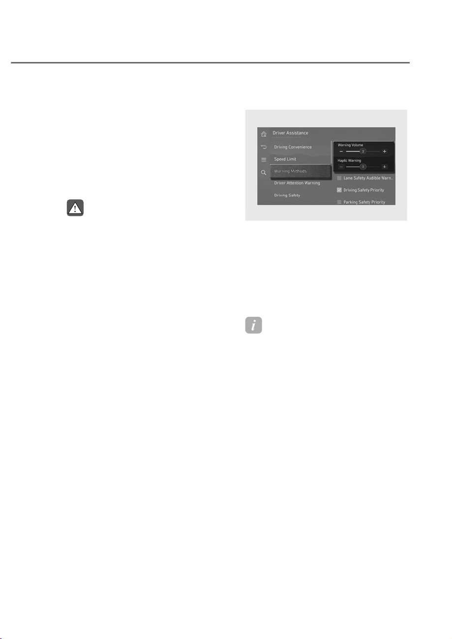
7-121
07
Rear Cross-Traffic Collision-
$YRLGDQFH$VVLVW6HWWLQJV
Rear Cross-Traffic Safety
With the engine on, select ‘Driver
$VVLVWDQFHɌ3DUNLQJ6DIHW\Ɍ5HDU&URVV
Traffic Safety’ from the Settings menu
to turn on Rear Cross-Traffic Collision-
Avoidance Assist and deselect to turn off
the function.
WARNING
:KHQWKHHQJLQHLVUHVWDUWHG5HDU
&URVV7UDIILF&ROOLVLRQ$YRLGDQFH$VVLVW
ZLOODOZD\VWXUQRQ+RZHYHULIȁ2IIȂLV
VHOHFWHGDIWHUWKHHQJLQHLVUHVWDUWHG
WKHGULYHUVKRXOGDOZD\VEHDZDUHRI
WKHVXUURXQGLQJVDQGGULYHVDIHO\
Warning methods
ORS073338N
ORS073338N
With the engine on, go to 'Driver
$VVLVWDQFHɌ:DUQLQJ0HWKRGVIURPWKH
Settings in the infotainment system to
select the following:
• Warning Volume: The warning volume
can be adjusted.
• Haptic Warning: The steering wheel
vibration can be set.
Information
• If you change the Warning Methods,
Warning Methods of other Driver
Assistance systems may change.
• Warning Method will maintain its last
setting even if the vehicle is restarted.
• The setting menu may not be available
for your vehicle depending on the
vehicle features and specifications.
• The Warning olume and Haptic
Warning cannot be turned off at the
same time. When one of the warning is
turned off the other is activated.
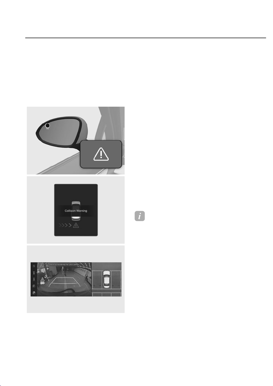
7-122
Driver Assistance System
Rear Cross-Traffic Collision-
$YRLGDQFH$VVLVW2SHUDWLRQ
Rear Cross-Traffic Collision-Avoidance
Assist will warn and control the vehicle
depending on collision risk level:
‘Collision Warning’, ‘Emergency Braking’
and ‘Stop vehicle and end brake control’.
ORS073235
ORS073235
ORS071249L
ORS071249L
ORS072248N
ORS072248N
Collision Warning
• To warn the driver of an approaching
vehicle from the rear left/right side
of your vehicle, the warning light
on the side view mirror will blink
and a warning will appear on the
instrument cluster. At the same time,
an audible warning will sound, and
the steering wheel will vibrate. If Rear
View Monitor is operating, a warning
will also appear on the infotainment
system screen.
• Rear Cross-Traffic Collision-Avoidance
Assist will operate when all the
following conditions are satisfied:
- The gear is shifted to R (Reverse)
- Vehicle speed is below 5 mph (8
km/h)
- The approaching vehicle is within
approximately 82 ft. (25 m) from the
left and right side of your vehicle
- The speed of the vehicle
approaching from the left and right
is above 3 mph (5 km/h)
Information
• If the operating conditions are satisfied,
there will be a warning whenever the
vehicle approaches from the left or
right side even though your vehicle
speed is 0 mph (0 km/h).
• The images and colors in the cluster
may differ depending on the cluster
type or theme selected from the cluster.
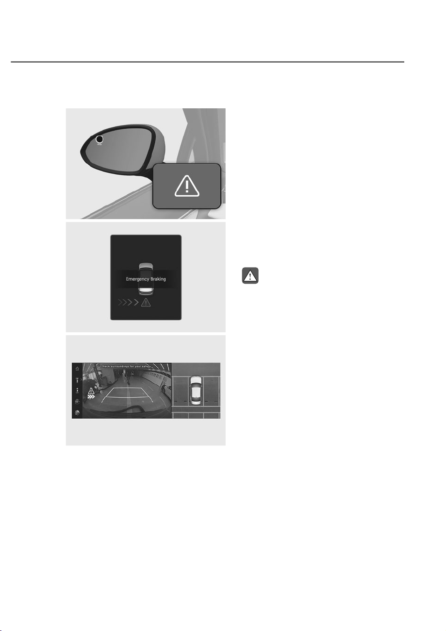
7-123
07
Emergency Braking
ORS073235
ORS073235
ORS071126L
ORS071126L
ORS072248N
ORS072248N
• To warn the driver of an approaching
vehicle from the rear left/right side
of your vehicle, the warning light on
the side view mirror will blink and a
warning message will appear on the
instrument cluster. At the same time,
an audible warning will sound, and the
steering wheel will vibrate. A warning
will also appear on the infotainment
system screen.
• Emergency braking will be assisted
to help prevent a collision with
approaching vehicles from the left
and right.
• Rear Cross-Traffic Collision-Avoidance
Assist will operate when all the
following conditions are satisfied:
- The gear is shifted to R (Reverse)
- Vehicle speed is below 5 mph (8
km/h)
- The approaching vehicle is within
approximately 5 ft. (1.5 m) from the
left and right side of your vehicle
- The speed of the vehicle
approaching from the left and right
is above 3 mph (5 km/h)
WARNING
Brake control ends when the conditions
RIWKHDSSURDFKLQJYHKLFOHIURPWKH
UHDUOHIWRUULJKWVLGHDUHDVEHORZ
• 7KHDSSURDFKLQJYHKLFOHLVRXWRIWKH
detecting range
• 7KHDSSURDFKLQJYHKLFOHSDVVHV
EHKLQG\RXUYHKLFOH
• 7KHDSSURDFKLQJYHKLFOHGRHVQRW
GULYHWRZDUG\RXUYHKLFOH
• 7KHDSSURDFKLQJYHKLFOHVSHHGVORZV
down
• 7KHGULYHUGHSUHVVHVWKHEUDNHSHGDO
with sufficient power

7-124
Driver Assistance System
Stop vehicle and end brake control
ORS071127L
ORS071127L
• When the vehicle is stopped due
to emergency braking, the ‘Drive
carefully’ warning message will
appear on the instrument cluster.
• For your safety, the driver should
depress the brake pedal immediately
and check the surroundings.
• Brake control will end after the vehicle
is stopped by emergency braking for
approximately 2 seconds.
• During emergency braking, braking
control by Rear Cross-Traffic Collision-
Avoidance Assist will automatically
cancel when the driver excessively
depresses the brake pedal.
WARNING
Take the following precautions when
using Rear Cross-Traffic Collision-
$YRLGDQFH$VVLVW
• )RU\RXUVDIHW\RQO\FKDQJHWKH
6HWWLQJVDIWHUSDUNLQJWKHYHKLFOHDWD
VDIHORFDWLRQ
• ,IDQ\RWKHUV\VWHPȂVZDUQLQJ
PHVVDJHLVGLVSOD\HGRUDXGLEOH
ZDUQLQJLVJHQHUDWHG5HDU&URVV
7UDIILF&ROOLVLRQ$YRLGDQFH$VVLVWȂV
ZDUQLQJPHVVDJHPD\QRWEH
GLVSOD\HGDQGDXGLEOHZDUQLQJPD\
QRWEHJHQHUDWHG
• <RXPD\QRWKHDUWKHZDUQLQJVRXQG
of Rear Cross-Traffic Collision-
$YRLGDQFH$VVLVWLIWKHVXUURXQGLQJ
LVQRLV\
• Rear Cross-Traffic Collision-
$YRLGDQFH$VVLVWPD\QRWRSHUDWHLI
WKHGULYHUDSSOLHVWKHEUDNHSHGDOWR
DYRLGFROOLVLRQ
• During Rear Cross-Traffic Collision-
$YRLGDQFH$VVLVWRSHUDWLRQWKH
YHKLFOHPD\VWRSVXGGHQO\LQMXULQJ
passengers and shifting loose
REMHFWV$OZD\VKDYHWKHVHDWEHOWRQ
DQGNHHSORRVHREMHFWVVHFXUHG
• (YHQLIWKHUHLVDSUREOHPZLWK5HDU
&URVV7UDIILF&ROOLVLRQ$YRLGDQFH
$VVLVWWKHYHKLFOHȂVEDVLFEUDNLQJZLOO
IXQFWLRQQRUPDOO\
• When Rear Cross-Traffic Collision-
$YRLGDQFH$VVLVWLVRSHUDWLQJ
EUDNLQJFRQWUROE\IXQFWLRQZLOO
DXWRPDWLFDOO\FDQFHOZKHQWKH
GULYHUH[FHVVLYHO\GHSUHVVHVWKH
DFFHOHUDWRUSHGDO
• Rear Cross-Traffic Collision-
$YRLGDQFH$VVLVWGRHVQRWRSHUDWH
LQDOOVLWXDWLRQVRUFDQQRWDYRLGDOO
FROOLVLRQV
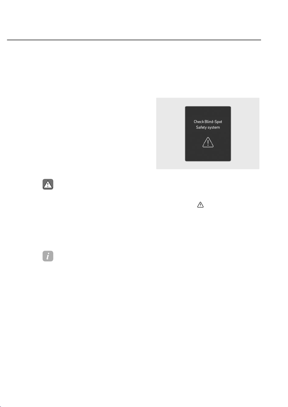
7-125
07
• Rear Cross-Traffic Collision-
$YRLGDQFH$VVLVWPD\ZDUQWKH
GULYHUODWHRUPD\QRWZDUQWKHGULYHU
GHSHQGLQJRQWKHURDGDQGGULYLQJ
FRQGLWLRQV
• 7KHGULYHUKDVWKHUHVSRQVLELOLW\WR
FRQWUROWKHYHKLFOH'RQRWVROHO\
depend on Rear Cross-Traffic
&ROOLVLRQ$YRLGDQFH$VVLVW5DWKHU
PDLQWDLQDVDIHEUDNLQJGLVWDQFHDQG
LIQHFHVVDU\GHSUHVVWKHEUDNHSHGDO
WRUHGXFHGULYLQJVSHHGRUWRVWRS
WKHYHKLFOH
• 1HYHUGHOLEHUDWHO\RSHUDWH5HDU
&URVV7UDIILF&ROOLVLRQ$YRLGDQFH
$VVLVWRQSHRSOHDQLPDOREMHFWV
HWF,WPD\FDXVHVHULRXVLQMXU\RU
GHDWK
CAUTION
7KHEUDNHFRQWUROPD\QRWRSHUDWH
SURSHUO\GHSHQGLQJRQWKHVWDWXVRI
(6&(OHFWURQLF6WDELOLW\&RQWURO
7KHUHZLOORQO\EHDZDUQLQJZKHQ
• 7KH(6&(OHFWURQLF6WDELOLW\&RQWURO
warning light is on
• (6&(OHFWURQLF6WDELOLW\&RQWUROLV
engaged in a different function
Information
If braking is assisted by Rear ross-
Traffic ollision-Avoidance Assist, the
driver must immediately depress the brake
pedal and check vehicle surroundings.
• After shifting the gear to R (Reverse),
braking control will operate once for
left and right vehicle approach.
Rear Cross-Traffic Collision-
$YRLGDQFH$VVLVW0DOIXQFWLRQ
and Limitations
Rear Cross-Traffic Collision-
Avoidance Assist malfunction
ORS071273L
ORS071273L
When Rear Cross-Traffic Collision-
Avoidance Assist is not working properly,
the ‘Check Blind-Spot Safety system’
warning message will appear on the
instrument cluster for several seconds,
and the master (
) warning light will
illuminate on the instrument cluster. If
this occurs, have the vehicle inspected
by an authorized retailer of Genesis
Branded products.
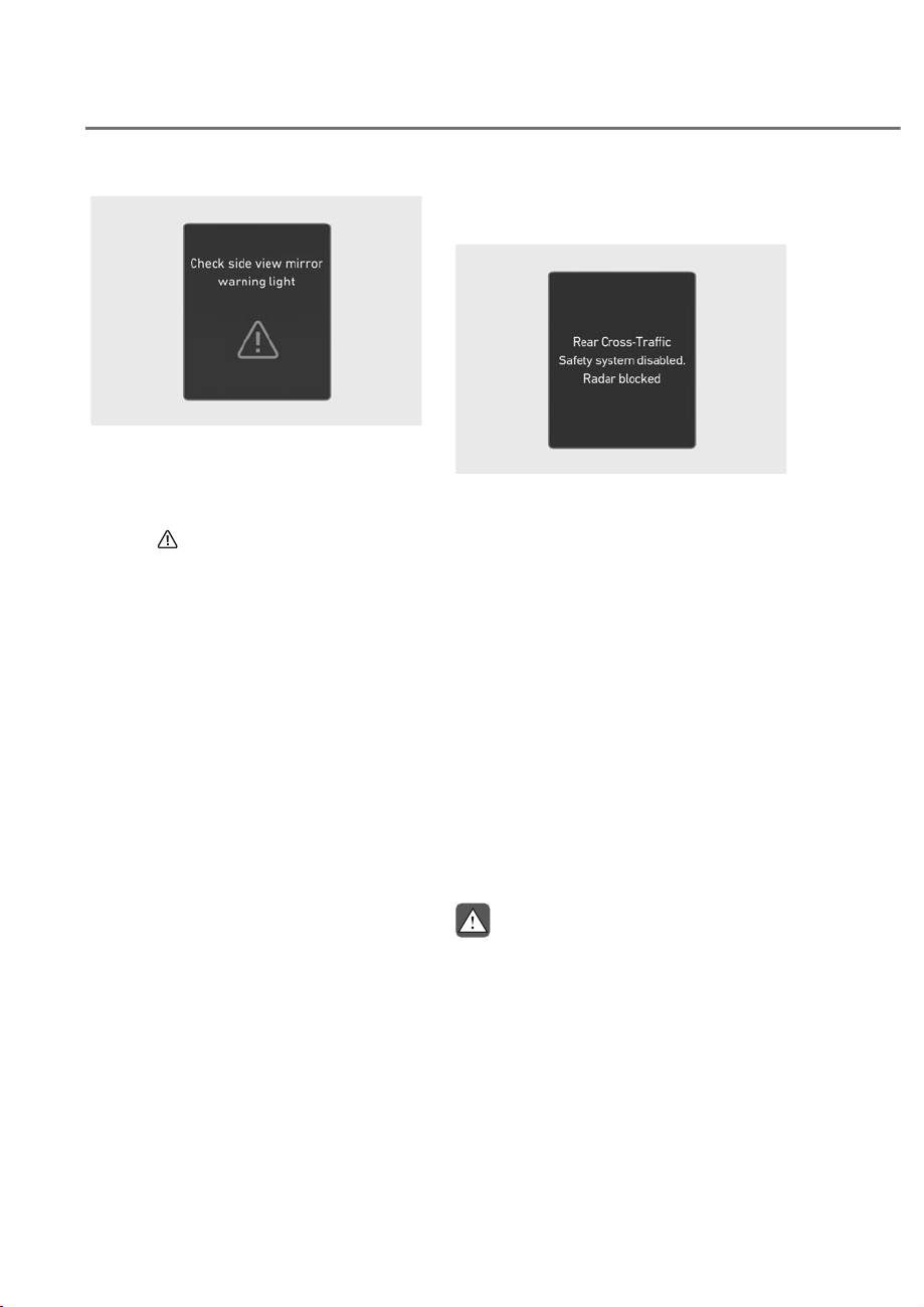
7-126
Driver Assistance System
OJWEV071275L
OJWEV071275L
When the side view mirror warning
light is not working properly, the ‘Check
side view mirror warning light’ warning
message will appear on the instrument
cluster for several seconds, and the
master (
) warning light will illuminate
on the instrument cluster. If this occurs,
have the vehicle inspected by an
authorized retailer of Genesis Branded
products.
Rear Cross-Traffic Collision-
Avoidance Assist disabled
ORS071287L
ORS071287L
When the rear bumper around the rear-
side radar or sensor is covered with
foreign material, such as snow or rain,
or installing a trailer or carrier, it can
reduce the detecting performance and
temporarily limit or disable Rear Cross-
Traffic Collision-Avoidance Assist.
If this occurs, the ‘Rear Cross-Traffic
Collision-Avoidance Assist disabled.
Radar blocked’ warning message will
appear on the instrument cluster.
Rear Cross-Traffic Collision-Avoidance
Assist will operate properly when
such foreign material or trailer, etc., is
removed.
If Rear Cross-Traffic Collision-Avoidance
Assist does not operate properly after it
is removed, have the vehicle inspected
by an authorized retailer of Genesis
Branded products.
WARNING
• (YHQWKRXJKWKHZDUQLQJPHVVDJH
GRHVQRWDSSHDURQWKHFOXVWHU5HDU
&URVV7UDIILF&ROOLVLRQ$YRLGDQFH
$VVLVWPD\QRWRSHUDWHSURSHUO\
• Rear Cross-Traffic Collision-
$YRLGDQFH$VVLVWPD\QRWRSHUDWH
SURSHUO\LQDQDUHDIRUH[DPSOH
RSHQWHUUDLQZKHUHDQ\VXEVWDQFH
are not detected after turning ON the
HQJLQH
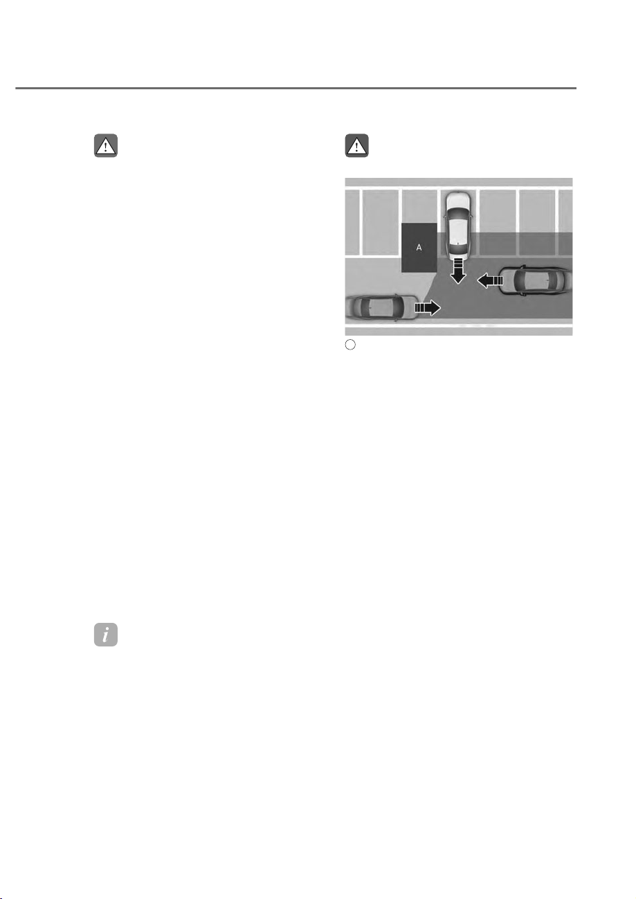
7-127
07
CAUTION
Turn off Rear Cross-Traffic Collision-
$YRLGDQFH$VVLVWWRLQVWDOORUUHPRYHD
WUDLOHUFDUULHURUDQRWKHUDWWDFKPHQW
Turn on Rear Cross-Traffic Collision-
$YRLGDQFH$VVLVWZKHQILQLVKHG
Limitations of Rear Cross-Traffic
Collision-Avoidance Assist
Rear Cross-Traffic Collision-Avoidance
Assist may not operate properly, or it
may operate unexpectedly under the
following circumstances:
• Departing from where trees or grass
are overgrown
• Departing from where roads are wet
• Speed of the approaching vehicle is
fast or slow
Braking control may not work, driver’s
attention is required in the following
circumstances:
• The vehicle severely vibrates while
driving over a bumpy road, uneven
road or concrete patch
• Driving on a slippery surface due to
snow, water puddle, ice, etc.
• The tire pressure is low or a tire is
damaged
• The braking system has been modified
• Remote Smart Parking Assist is
operating (if equipped)
Information
For more details on the limitations of the
rear corner radar, refer to “Blind-Spot
ollision-Avoidance Assist (B A)” section
in this chapter.
WARNING
• 'ULYLQJQHDUDYHKLFOHRUVWUXFWXUH
ORS071086
ORS071086
A
: Structure
Rear Cross-Traffic Collision-
$YRLGDQFH$VVLVWPD\EHOLPLWHG
ZKHQGULYLQJQHDUDYHKLFOHRU
VWUXFWXUHDQGPD\QRWGHWHFWWKH
YHKLFOHDSSURDFKLQJIURPWKHOHIWRU
ULJKW,IWKLVRFFXUVWKHIXQFWLRQPD\
QRWZDUQWKHGULYHURUFRQWUROWKH
EUDNHVZKHQQHFHVVDU\
$OZD\VFKHFN\RXUVXUURXQGLQJV
ZKLOHEDFNLQJXS
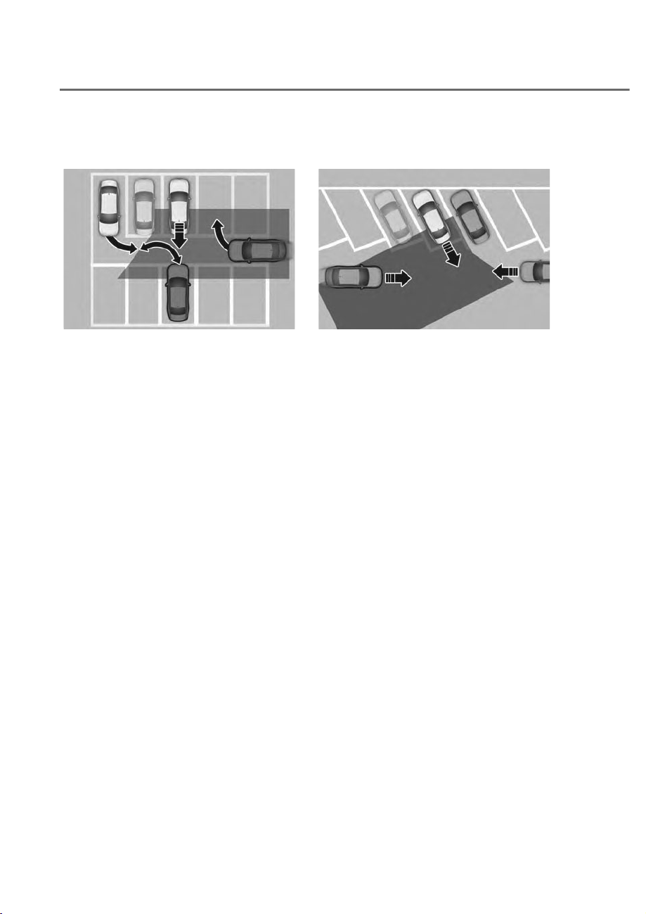
7-128
Driver Assistance System
• :KHQWKHYHKLFOHLVLQDFRPSOH[
SDUNLQJHQYLURQPHQW
ORS071087
ORS071087
Rear Cross-Traffic Collision-
$YRLGDQFH$VVLVWPD\GHWHFWYHKLFOHV
which are parking or pulling out
QHDU\RXUYHKLFOHIRUH[DPSOHD
YHKLFOHOHDYLQJEHVLGH\RXUYHKLFOH
DYHKLFOHSDUNLQJRUSXOOLQJRXWLQ
WKHUHDUDUHDDYHKLFOHDSSURDFKLQJ
\RXUYHKLFOHPDNLQJDWXUQHWF
,IWKLVRFFXUVWKHIXQFWLRQPD\
XQQHFHVVDULO\ZDUQWKHGULYHUDQG
FRQWUROWKHEUDNH
$OZD\VFKHFN\RXUVXUURXQGLQJV
ZKLOHEDFNLQJXS
• :KHQWKHYHKLFOHLVSDUNHG
GLDJRQDOO\
ORS071138
ORS071138
Rear Cross-Traffic Collision-
$YRLGDQFH$VVLVWPD\EHOLPLWHG
ZKHQEDFNLQJXSGLDJRQDOO\
DQGPD\QRWGHWHFWWKHYHKLFOH
DSSURDFKLQJIURPWKHOHIWRUULJKW
,IWKLVRFFXUVWKHIXQFWLRQPD\QRW
ZDUQWKHGULYHURUFRQWUROWKHEUDNHV
ZKHQQHFHVVDU\
$OZD\VFKHFN\RXUVXUURXQGLQJV
ZKLOHEDFNLQJXS
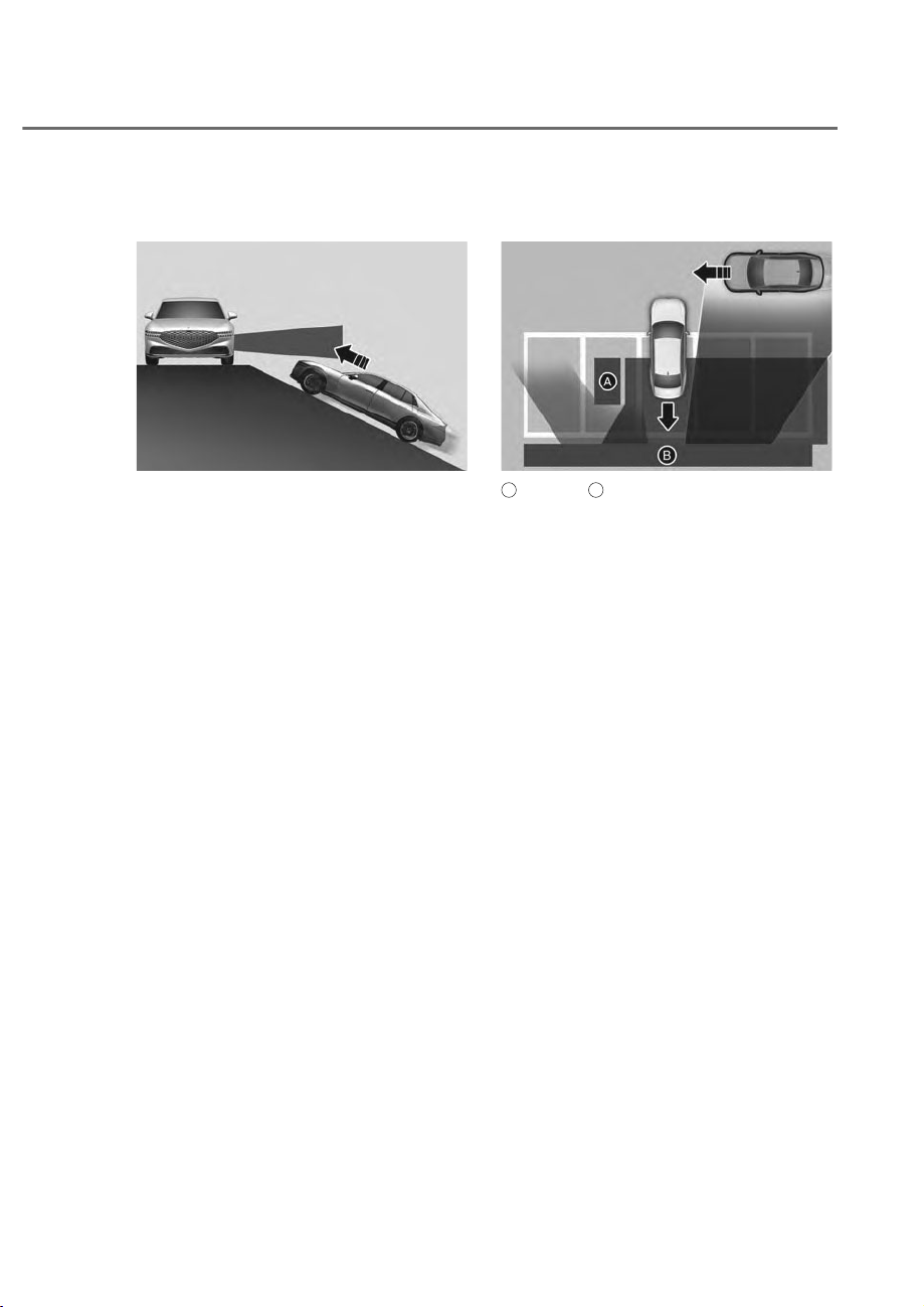
7-129
07
• :KHQWKHYHKLFOHLVRQRUQHDUD
slope
ORS071054
ORS071054
Rear Cross-Traffic Collision-
$YRLGDQFH$VVLVWPD\EHOLPLWHG
ZKHQWKHYHKLFOHLVRQDXSKLOORU
GRZQKLOOVORSHRUQHDULWDQGPD\
QRWGHWHFWWKHYHKLFOHDSSURDFKLQJ
IURPWKHOHIWRUULJKW,IWKLVRFFXUV
WKHIXQFWLRQPD\QRWZDUQWKH
GULYHURUFRQWUROWKHEUDNHVZKHQ
QHFHVVDU\
$OZD\VFKHFN\RXUVXUURXQGLQJV
ZKLOHEDFNLQJXS
• 3XOOLQJLQWRWKHSDUNLQJVSDFHZKHUH
there is a structure
ORS071088
ORS071088
A
: Structure,
B
: Wall
Rear Cross-Traffic Collision-
$YRLGDQFH$VVLVWPD\GHWHFWYHKLFOHV
SDVVLQJE\LQIURQWRI\RXZKHQ
SDUNLQJLQUHYHUVHLQWRDSDUNLQJ
space with a wall or structure in the
UHDURUVLGHDUHD,IWKLVRFFXUVWKH
IXQFWLRQPD\XQQHFHVVDULO\ZDUQWKH
GULYHUDQGFRQWUROWKHEUDNH
$OZD\VFKHFN\RXUVXUURXQGLQJV
ZKLOHEDFNLQJXS
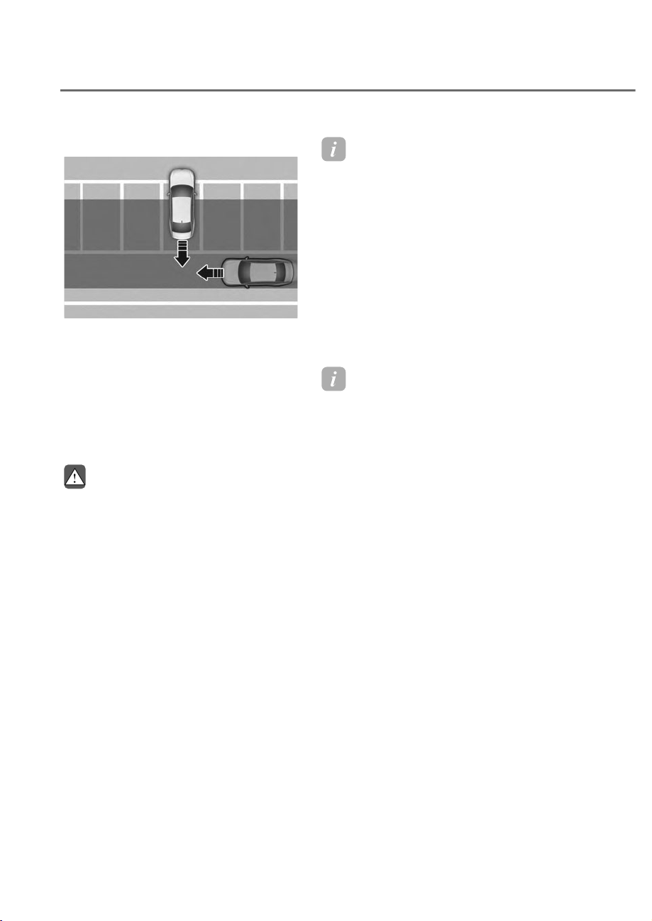
7-130
Driver Assistance System
• :KHQWKHYHKLFOHLVSDUNHGUHDUZDUG
ORS071089
ORS071089
Rear Cross-Traffic Collision-
$YRLGDQFH$VVLVWPD\GHWHFWYHKLFOHV
SDVVLQJE\EHKLQG\RXZKHQSDUNLQJ
LQUHYHUVHLQWRDSDUNLQJVSDFH
,IWKLVRFFXUVWKHIXQFWLRQPD\
XQQHFHVVDULO\ZDUQWKHGULYHUDQG
FRQWUROWKHEUDNH
$OZD\VFKHFN\RXUVXUURXQGLQJV
ZKLOHEDFNLQJXS
WARNING
• :KHQ\RXDUHWRZLQJDWUDLOHURU
DQRWKHUYHKLFOHWXUQRII5HDU&URVV
7UDIILF&ROOLVLRQ$YRLGDQFH$VVLVWIRU
VDIHW\UHDVRQV
• Rear Cross-Traffic Collision-
$YRLGDQFH$VVLVWPD\QRWRSHUDWH
SURSHUO\LILQWHUIHUHGE\VWURQJ
HOHFWURPDJQHWLFZDYHV
• Rear Cross-Traffic Collision-
$YRLGDQFH$VVLVWPD\QRWRSHUDWH
IRUȺVHFRQGVDIWHUWKHYHKLFOHLV
VWDUWHGRUWKHUHDUFRUQHUUDGDUVDUH
LQLWLDOL]HG
• ,IWKHYHKLFOHLVWXUQHGRIIDQG
restarted while the camera is
EORFNHGRUPDOIXQFWLRQHGWKH
FRQGLWLRQLVPDLQWDLQHG7KHUHIRUH
Rear Cross-Traffic Collision-
$YRLGDQFH$VVLVWLVPD\QRWRSHUDWH
SURSHUO\
Information
This device complies with Part 15 of the
F rules. peration is sub ect to the
following three conditions:
1. This device may not cause harmful
interference, and
2. This device must accept any
interference received, including
interference that may cause undesired
operation.
3. hanges or modifications not expressly
approved by the party responsible
for compliance could void the user’s
authority to operate the device.
Information
Radio frequency radiation exposure
information:
This equipment complies with F
radiation exposure limits set forth for an
uncontrolled environment.This equipment
should be installed and operated with
minimum distance of 8 in. (20 cm) between
the radiator (antenna) and your body.
This transmitter must not be co-located or
operating in con unction with any other
antenna or transmitter.

7-131
07
Forward/Side/Reverse Parking Distance
Warning can help warn the driver if an
obstacle is detected within a certain
distance when the vehicle is moving
forward or in reverse at low speeds.
Detecting sensor
ORS071014
ORS071014
ORS072017N
ORS072017N
A
: Front ultrasonic sensors
B
: Front side ultrasonic sensors
C
: Rear side ultrasonic sensors
D
: Rear ultrasonic sensors
Refer to the picture above for the
detailed location of the detecting
sensors.
3DUNLQJ'LVWDQFH:DUQLQJ
Settings
Warning methods
ORS073337N
ORS073337N
With the engine on, go to 'Driver
$VVLVWDQFHɌ:DUQLQJ0HWKRGVIURPWKH
Settings in the infotainment system to
select the following:
• Warning Volume: The warning volume
can be adjusted. If you turn off the
Warning Volume, for your safety, the
function may warn you with a low
volume.
Information
• If you change the Warning Methods,
Warning Methods of other Driver
Assistance systems may change.
• Warning Method will maintain its last
setting even if the vehicle is restarted.
• The setting menu may not be available
for your vehicle depending on the
vehicle features and specifications.
)25:$5'6,'(5(9(56(3$5.,1*',67$1&(:$51,1*ʚ3':ʛ

7-132
Driver Assistance System
Parking Distance Warning Auto On
To use Parking Distance Warning Auto
On function, select ‘Driver Assistance
Ɍ3DUNLQJ6DIHW\Ɍ3DUNLQJ'LVWDQFH
Warning Auto On’ from the infotainment
system Settings menu.
Information
• When Parking Distance Warning Auto
n is selected, the Parking Safety
button indicator (
) stays on.
3DUNLQJ'LVWDQFH:DUQLQJ
Operation
Parking Safety button
OJWEV071113
OJWEV071113
Press the Parking Safety ( ) button
to turn on Forward/Reverse Parking
Distance Warning. Press the button again
to turn off the function.
• When the gear is shift to R (Reverse),
Parking Distance Warning will
automatically turn on (Parking Safety
button indicator on).
• When the gear is in R (Reverse),
Parking Distance Warning does not
turn off even if the Parking Safety
button is pressed.
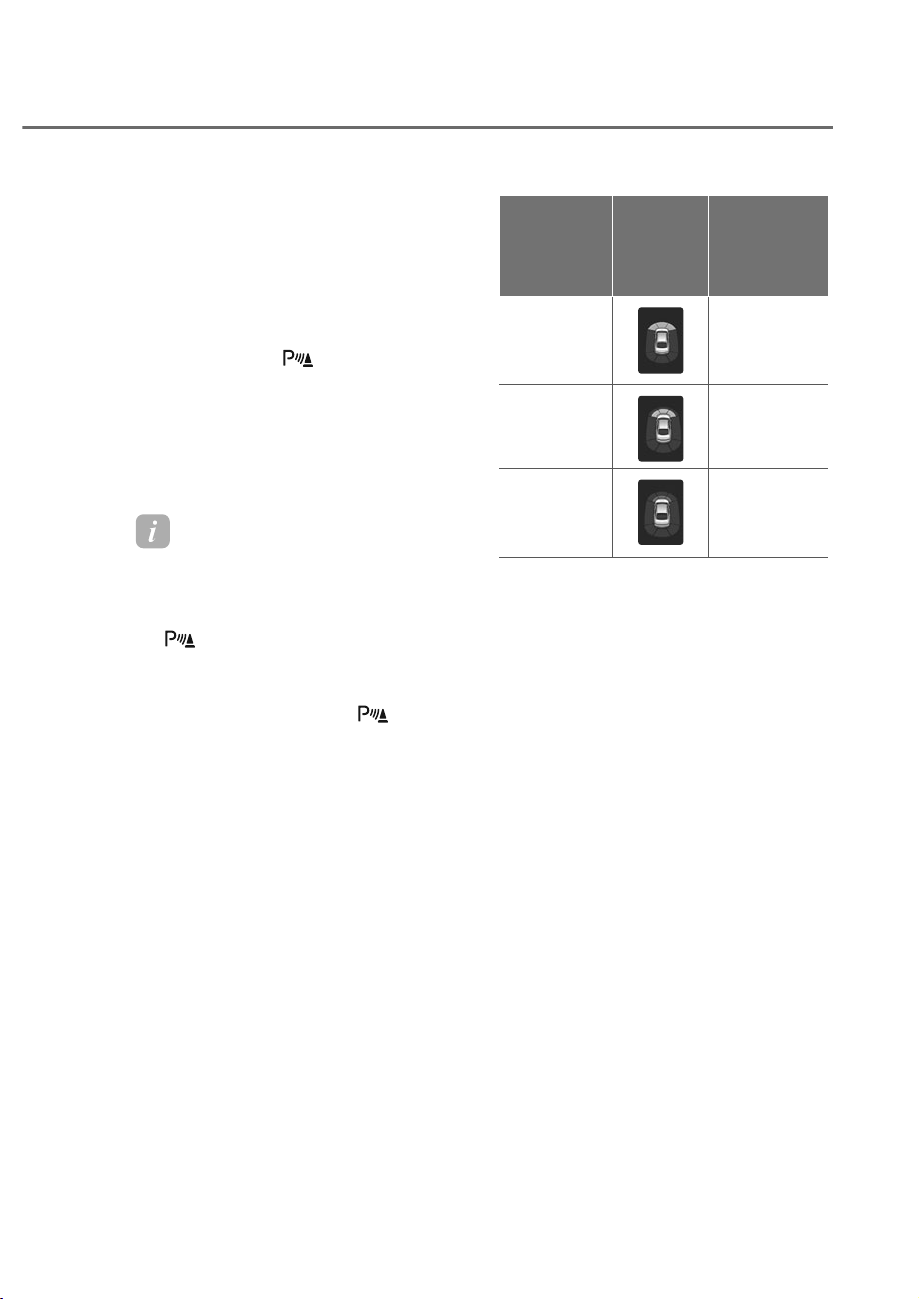
7-133
07
Forward Parking Distance Warning
Forward Parking Distance Warning will
operate under the following conditions.
• The gear is shifted from R (Reverse)
to D (Drive) with Reverse Parking
Distance Warning on
• The gear is in D (Drive) and the
Parking Safety (
) button indicator
light is on
• ‘Parking Distance Warning Auto On’ is
selected from the Settings menu and
the gear is in D (Drive)
• Vehicle speed is below 6 mph (10
km/h).
Information
• Forward Parking Distance Warning
does not operate when the vehicle's
forward speed is above 6 mph (10
km/h) even when the Parking Safety
(
) button indicator is on. Forward
Parking Distance Warning will operate
again when the vehicle's forward speed
decreases below 6 mph (10 km/h)
while the Parking Safety (
) button
indicator is on.
• Forward Parking Distance Warning is
deactivated if the vehicle speed reaches
above 18 mph (30 km/h). It will not
reactivate although the vehicle speed
drops below 6 mph (10 km/h). ( nly
when Parking Warning Auto n is not
selected)
Distance
IURPREMHFW
Warning
indicator
when
GULYLQJ
forward
Warning
sound
24~40 in.
(60~100 cm)
Buzzer beeps
intermittently
12~24 in.
(30~60 cm)
Beeps more
frequently
within 12 in.
(30 cm)
Beeps
continuously
• The corresponding indicator will
illuminate whenever each ultrasonic
sensor detects a person, animal or
object in its sensing range. Also an
audible warning will sound.
• When more than two objects are
detected at the same time, the closest
one will be warned with an audible
warning.
• The shape of the indicator in the
illustration may differ from the actual
vehicle.
• The warning indicator in the front
corner area will illuminate and an
audible warning will sound while your
vehicle is reversing.
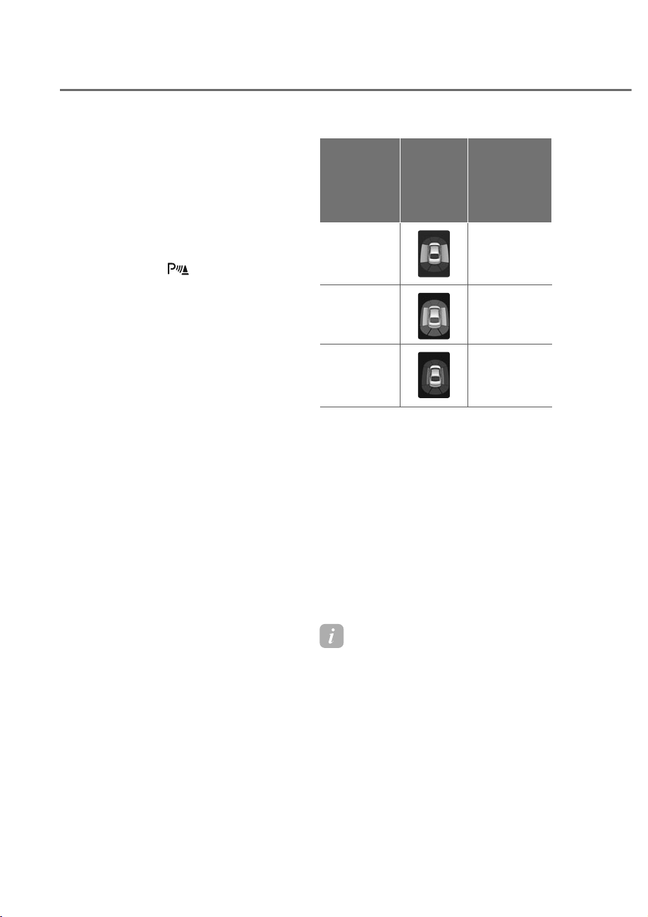
7-134
Driver Assistance System
Side Parking Distance Warning
Side Parking Distance Warning will
operate under the following conditions.
• The gear is shifted to R (Reverse).
• The gear is shifted from R (Reverse)
to D (Drive) with Reverse Parking
Distance Warning on
• The gear is in D (Drive) and the
Parking Safety (
) button indicator
light is on
• ‘Parking Distance Warning Auto On’ is
selected from the Settings menu and
the gear is in D (Drive)
• Vehicle speed is below 6 mph (10
km/h).
Distance
IURPREMHFW
Warning
indicator
when
GULYLQJ
forward/
rearward
Warning
sound
24~40 in.
(60~100 cm)
-
12~24 in.
(30~60 cm)
-
within 12 in.
(30 cm)
Beeps
continuously
• The corresponding indicator will
illuminate whenever each ultrasonic
sensor detects a person, animal or
object in its sensing range.
• If an object located within 12 in. (30
cm) from the side of the vehicle's path
is detected, an audible warning will
sound.
• If an object outside the side of the
vehicle's path is detected, the warning
indicator will be displayed.
• The shape of the indicator in the
illustration may differ from the actual
vehicle.
Information
Side Parking Distance Warning operated
only when Forward or Rearward Parking
Distance Warning is on.
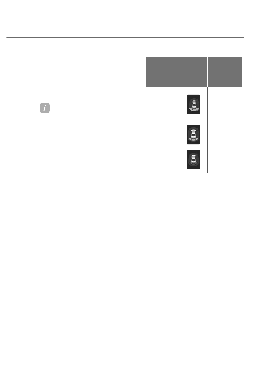
7-135
07
Reverse Parking Distance Warning
Reverse Parking Distance Warning will
operate under the following conditions.
• The gear is shifted to R (Reverse).
• Vehicle speed is below 6 mph (10
km/h).
Information
Parking Distance Warning detects and
warns the driver of both rear and front
corners, when the vehicle speed is below 6
mph (10 km/h).
Distance
IURPREMHFW
Warning
indicator
when
GULYLQJ
EDFNZDUG
Warning
sound
24~48 in.
(60~120 cm)
(Forward
Corner:
24~40 in.
(60~100 cm))
Buzzer beeps
intermittently
12~24 in.
(30~60 cm)
Beeps more
frequently
within 12 in.
(30 cm)
Beeps
continuously
• The corresponding indicator will
illuminate whenever each ultrasonic
sensor detects a person, animal or
object in its sensing range. Also an
audible warning will sound.
• When more than two objects are
detected at the same time, the closest
one will be warned with an audible
warning.
• The shape of the indicator in the
illustration may differ from the actual
vehicle.
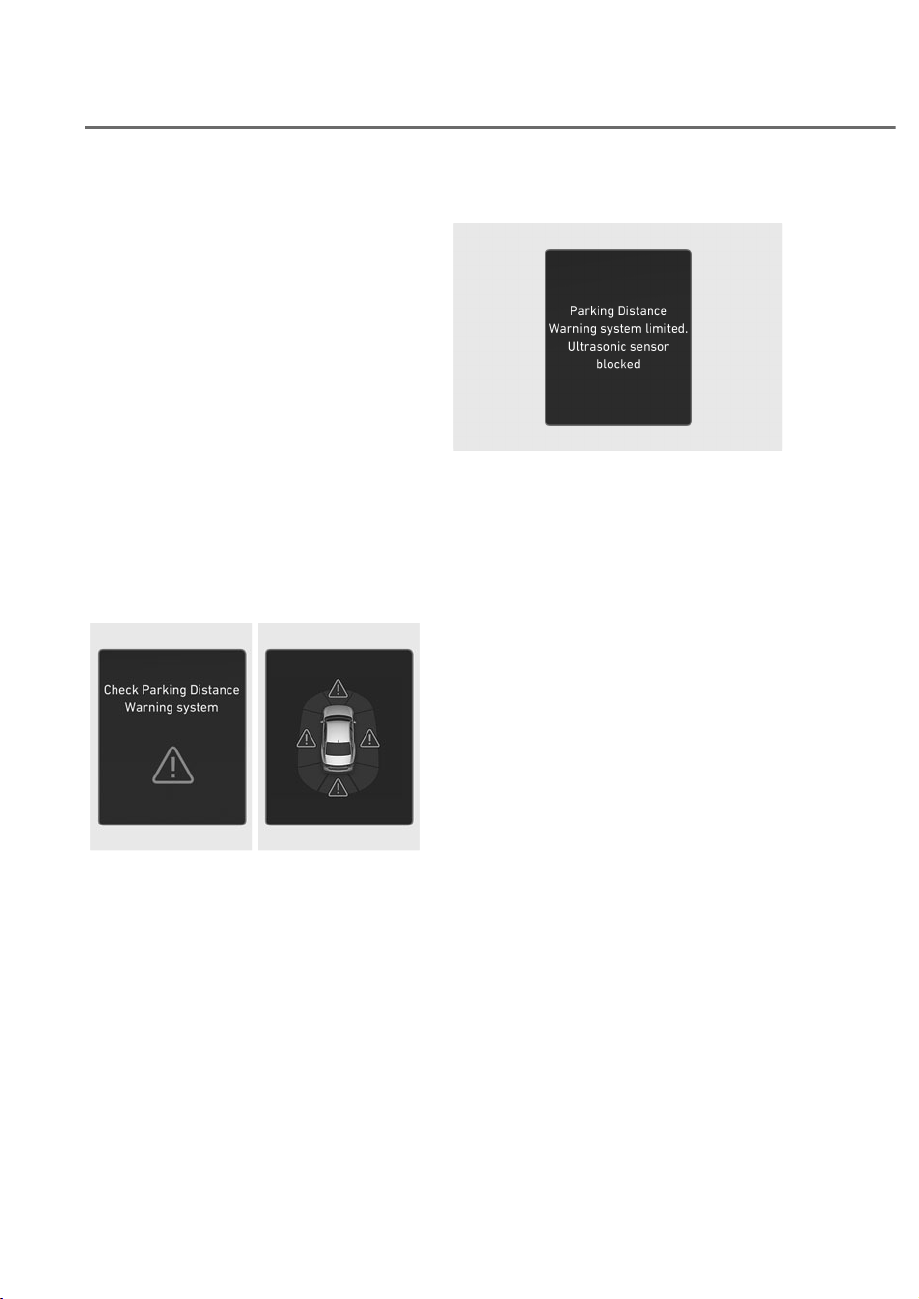
7-136
Driver Assistance System
3DUNLQJ'LVWDQFH:DUQLQJ
0DOIXQFWLRQDQG/LPLWDWLRQV
Parking Distance Warning
malfunction
After starting the engine, a beep will
sound when the gear is shifted to R
(Reverse) to indicate Parking Distance
Warning is operating properly.
However, if one or more of the following
occurs, first check whether the ultrasonic
sensor is damaged or blocked with
foreign material. If it still does not work
properly, have the vehicle inspected by
an authorized retailer of Genesis Branded
products.
• The audible warning does not sound.
• The buzzer sounds intermittently.
• The ‘Check Parking Distance Warning
system’ warning message appears on
the instrument cluster.
OJWEV071232L
OJWEV071232L
ORS071211
ORS071211
Parking Distance Warning disabled
OJWEV071233L
OJWEV071233L
If this occurs the ‘Parking Distance
Warning system limited. Ultrasonic
sensor blocked’ warning message
appears on the instrument cluster.
Parking Distance Warning will operate
properly when snow, rain or foreign
material is removed. If Parking Distance
Warning does not operate properly
after obstruction (snow, rain, or foreign
material) is removed (including trailer,
carrier, etc., from the rear bumper), have
the vehicle inspected by an authorized
retailer of Genesis Branded products.

7-137
07
Limitations of Parking Distance
Warning
• Parking Distance Warning may not
operate properly when:
- There is excessive moisture or frost
on the sensor
- Sensor is covered with foreign
substance, such as snow or water
(Parking Distance Warning will
operate properly when such
substance is removed.)
- The weather is extremely hot or cold
- The sensor or sensor assembly is
disassembled
- The surface of the sensor is pressed
hard or hit with a hard object
- The surface of the sensor is
scratched with a sharp object
- The sensors or its surrounding
area is directly sprayed with high
pressure washer
• Parking Distance Warning may
malfunction when:
- Heavy rain or water spray is present
- Water flows on the surface of the
sensor
- Affected by another vehicle’s
sensors
- The sensor is covered with snow or
ice
- Driving on uneven road, gravel
roads or bushes
- Objects that generates ultrasonic
waves are near the sensor
- License plate is installed in a
different spot from the original
location
- The vehicle bumper height or
ultrasonic sensor installation has
been modified
- Attaching equipment or accessories
next to the ultrasonic sensors
• The following objects may not be
detected:
- Sharp or slim objects, such as ropes,
chains or small poles.
- Narrow objects, such as corners of a
square column
- Objects, which tend to absorb
sensor frequency, such as clothes,
spongy material or snow.
- Objects smaller than 40 in. (100 cm)
in length and narrower than 6 in. (14
cm) in diameter.
- Pedestrians, animals or objects
that are very close to the ultrasonic
sensors
- An object in the side space between
the front corner ultrasonic sensor
and the rear corner ultrasonic
sensor or an object approaching the
side space

7-138
Driver Assistance System
WARNING
• 3DUNLQJ'LVWDQFH:DUQLQJLV
DVXSSOHPHQWDOIXQFWLRQ7KH
RSHUDWLRQRI3DUNLQJ'LVWDQFH
:DUQLQJFDQEHDIIHFWHGE\VHYHUDO
IDFWRUVLQFOXGLQJHQYLURQPHQWDO
FRQGLWLRQV,WLVWKHUHVSRQVLELOLW\RI
WKHGULYHUWRDOZD\VFKHFNWKHIURQW
DQGUHDUYLHZVEHIRUHDQGZKLOH
SDUNLQJ
• <RXUQHZYHKLFOHZDUUDQW\GRHVQRW
FRYHUDQ\DFFLGHQWVRUGDPDJHWR
WKHYHKLFOHGXHWRWKHPDOIXQFWLRQRI
3DUNLQJ'LVWDQFH:DUQLQJ
• 3D\FORVHDWWHQWLRQZKHQGULYLQJ
QHDUREMHFWVSHGHVWULDQVDQG
HVSHFLDOO\FKLOGUHQ6RPHREMHFWV
PD\QRWEHGHWHFWHGE\WKH
XOWUDVRQLFVHQVRUVGXHWRWKHREMHFWV
GLVWDQFHVL]HRUPDWHULDODOORI
ZKLFKFDQOLPLWWKHHIIHFWLYHQHVVRI
WKHVHQVRU
• 3DUNLQJ'LVWDQFH:DUQLQJGRHVQRW
ZDUQ\RXLQWKHRUGHURIGHWHFWLRQ
,WYDULHVGHSHQGLQJRQWKHVSHHGRI
WKHYHKLFOHRUWKHVKDSHRIDSHUVRQ
DQLPDORUREMHFW
• ,IWKH3DUNLQJ'LVWDQFH:DUQLQJ
GRHVQRWRSHUDWHSURSHUO\KDYHWKH
YHKLFOHLQVSHFWHGE\DQDXWKRUL]HG
UHWDLOHURI*HQHVLV%UDQGHGSURGXFWV
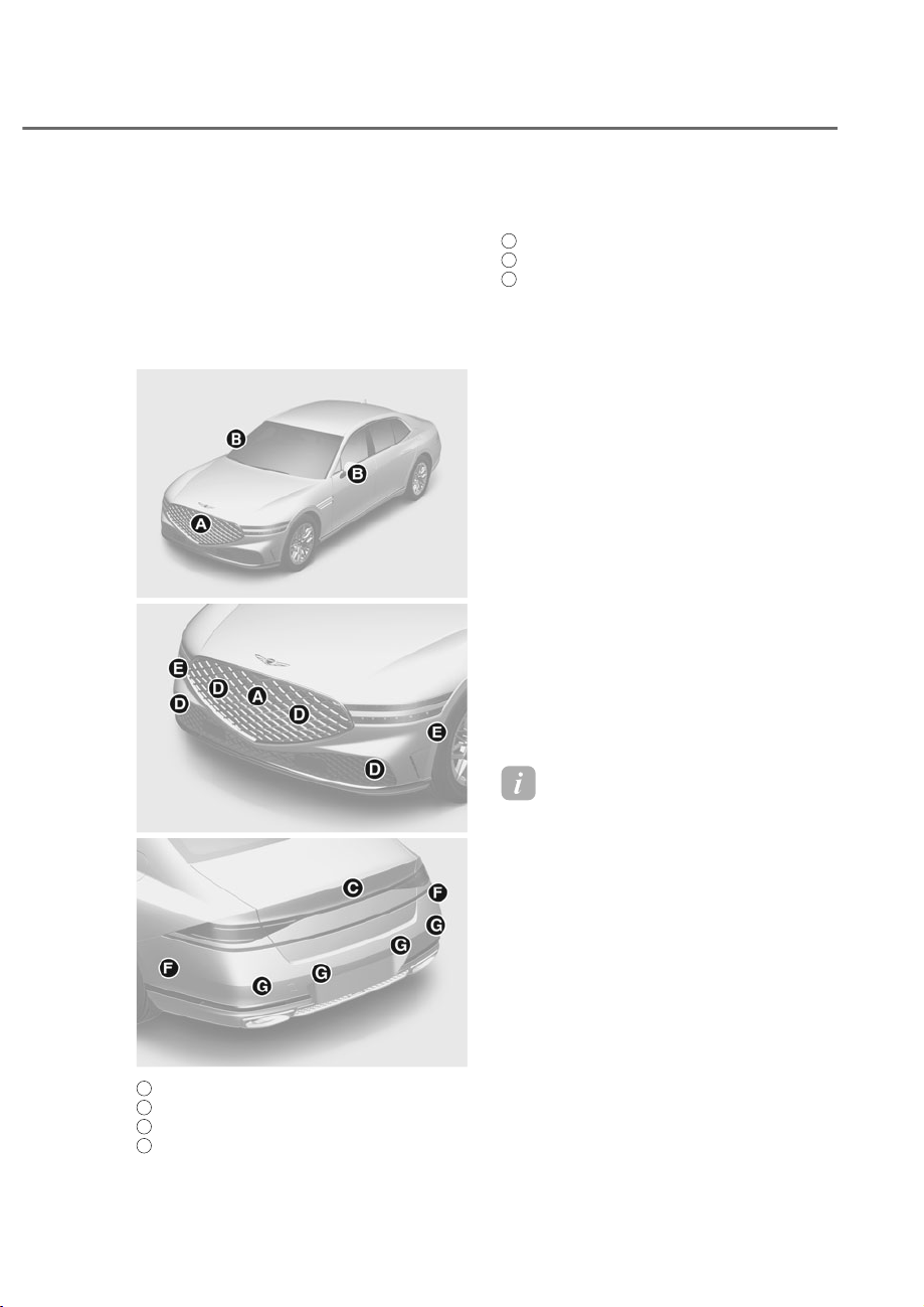
7-139
07
Forward/Side/Reverse Parking Collision-
Avoidance Assist can warn the driver or
assist with braking to help reduce the
possibility of collision with a pedestrian
or an object while driving at low speed.
Detecting sensor
ORS072191N
ORS072191N
ORS072013N
ORS072013N
ORS072016N
ORS072016N
A
: Wide-front view camera
B
: Wide-Side view camera (Below the side view mirror)
C
: Wide-rear view camera
D
: Front ultrasonic sensor
E
: Front side ultrasonic sensor
F
: Rear side ultrasonic sensor
G
: Rear ultrasonic sensor
Refer to the picture above for the
detailed location of the detecting
sensors.
3DUNLQJ&ROOLVLRQ$YRLGDQFH
Assist Settings
Parking Safety
With the engine on, select or deselect
ȁ'ULYHU$VVLVWDQFHɌ3DUNLQJ6DIHW\ȂIURP
the Settings menu to set whether to use
each function.
• If ‘Front/Side Safety’ is selected,
Parking Collision-Avoidance Assist will
warn the driver and assist with braking
when a collision with a pedestrian or
an object is imminent from the front
or the side.
• If ‘Rear Safety' is selected, Parking
Collision-Avoidance Assist will warn
the driver and assist with braking
when a collision with a pedestrian or
an object is imminent from behind.
Information
'Forward/Side Safety' can be selected
only when 'Rear Safety' is selected. If
the engine is restarted, 'Rear Safety'
is selected and 'Forward/Side safety'
maintains the last setting.
)25:$5'6,'(5(9(56(3$5.,1*&2//,6,21ʏ$92,'$1&(
$66,67ʚ3&$ʛʚ,)(48,33('ʛ
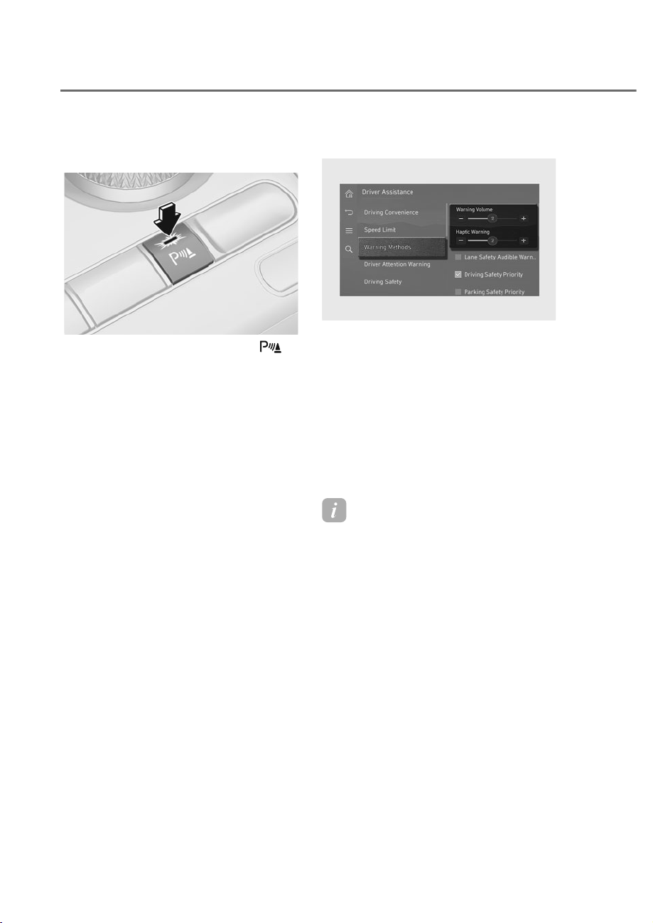
7-140
Driver Assistance System
Turning Parking Collision Avoidance
Assist On/Off
ORS071019
ORS071019
Press and hold the Parking Safety ( )
button more than 2 seconds, to turn the
Parking Collision-Avoidance Assist on or
off.
Warning methods
ORS073338N
ORS073338N
With the engine on, go to 'Driver
$VVLVWDQFHɌ:DUQLQJ0HWKRGVIURPWKH
Settings in the infotainment system to
select the following:
• Warning Volume: The warning volume
can be adjusted. If you turn off the
Warning Volume, for your safety, the
function may warn you with a low
volume.
• Haptic Warning: The steering wheel
vibration can be set.
Information
• If you change the Warning Methods,
Warning Methods of other Driver
Assistance systems may change.
• Warning Method will maintain its last
setting even if the vehicle is restarted.
• The setting menu may not be available
for your vehicle depending on the
vehicle features and specifications.
• The Warning olume and Haptic
Warning cannot be turned off at the
same time. When one of the warning is
turned off the other is activated.

7-141
07
3DUNLQJ&ROOLVLRQ$YRLGDQFH
Assist Operation
Operating conditions
Select ‘Rear Safety’ from the ‘Parking
Safety’ menu of the infotainment system.
Parking Collision-Avoidance Assist is
enabled when the following conditions
are satisfied:
Rear Safety
• The trunk and door are closed
• The Electronic Parking Brake (EPB) is
released
• A trailer is not connected
• The gear is shifted to R (Reverse)
• Vehicle speed is below 6 mph (10
km/h) (detecting pedestrians)
• Vehicle speed is below 2 mph (4 km/h)
(detecting objects)
• Parking Collision-Avoidance Assist
components such as the wide-rear
view camera and the rear ultrasonic
sensors are in normal conditions
Front/Side Safety
• The trunk and door are closed
• The Electronic Parking Brake (EPB) is
released
• A trailer is not connected
• The gear is shifted to R (Reverse) or D
(Drive)
• Vehicle speed is below 2 mph (4 km/h)
(for pedestrians, objects)
• Parking Collision-Avoidance Assist
components such as the wide-rear
view camera and the rear ultrasonic
sensors are in normal conditions
When Parking Collision-Avoidance Assist
activates, a line appears behind the
vehicle image in the instrument cluster.
• Rear Safety: Behind the vehicle image
• Front/Side Safety: In front of vehicle
image
ORS071131
ORS071131
Information
Parking ollision-Avoidance Assist
operates only once after shifting the gear
to R (Reverse) or D (Drive). To reactivate
Parking ollision-Avoidance Assist, shift
the gear from another gear to R (Reverse)
or D (Drive).
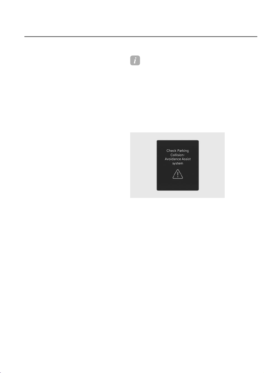
7-142
Driver Assistance System
Parking Collision-Avoidance Assist
If Parking Collision-Avoidance Assist
detects a risk of collision around the
vehicle with a pedestrian or an object,
Parking Collision-Avoidance Assist will
warn the driver with an audible warning
and warning message on the instrument
cluster. If the infotainment screen is on, a
warning will appear on the screen.
If collision is imminent, Parking Collision-
Avoidance Assist will assist you with
braking.
Front/Side Safety
Braking assist is released 2 seconds
after shifting to D (drive) and 5 minutes
after shifting to R (reverse). Immediately
depress the brake pedal and check
vehicle surroundings.
Braking assist is also released in the
following conditions when:
• The gear is shifted to P (Park) or other
positions but N(Neutral)
• The brake pedal is depressed with
sufficient power
Rear Safety
Braking assist is released after 5 minutes.
Immediately depress the brake pedal and
check vehicle surroundings.
Braking assist is also released in the
following conditions when:
• The gear is shifted to P (Park) or D
(Drive)
• The brake pedal is depressed with
sufficient power
Information
When Parking ollision-Avoidance Assist
is activated while reversing, braking
control will be released after 5 minutes
and the Electronic Parking Brake (EPB)
will be engaged.
3DUNLQJ&ROOLVLRQ$YRLGDQFH
$VVLVW0DOIXQFWLRQDQG
Limitations
Parking Collision-Avoidance Assist
malfunction
ORS072223N
ORS072223N
When Parking Collision-Avoidance
Assist or other related functions are
not working properly, the ‘Check
Parking Collision-Avoidance Assist
system’ warning message will appear
on the instrument cluster, and Parking
Collision-Avoidance Assist will turn
off automatically. Have the vehicle
inspected by an authorized retailer of
Genesis Branded products.
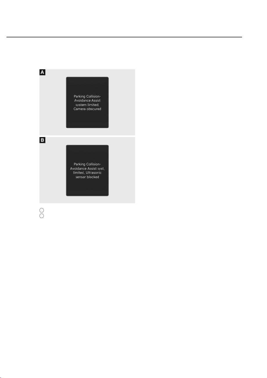
7-143
07
Parking Collision-Avoidance Assist
disabled
ORS072224N
ORS072224N
ORS072225N
ORS072225N
A
: Camera,
B
: Ultrasonic sensor
Warning message
The ‘Parking Collision-Avoidance Assist
system limited. Camera obscured’ or
‘Parking Collision-Avoidance Assist
syst. limited. Ultrasonic sensor blocked’
warning message will appear on the
instrument cluster if the following
situations occur:
• The camera(s) or ultrasonic sensor(s)
is covered with foreign material, such
as snow or rain, etc.
• There is inclement weather, such as
heavy snow, heavy rain, etc.
If this occurs, Parking Collision-
Avoidance Assist may turn off or may
not operate properly. Check whether
the cameras and ultrasonic sensors are
clean.
Limitations of Parking Collision-
Avoidance Assist
Parking Collision-Avoidance Assist may
not assist braking or warn the driver even
if there are pedestrians or objects under
the following circumstances:
• Problems with vehicle
- Any non-factory equipment or
accessory is installed
- Your vehicle is unstable due to an
accident or other causes
- Bumper height or rear ultrasonic
sensor installation has been
modified
- Wide view camera(s) or ultrasonic
sensor(s) is damaged
- Wide view camera(s) or the
ultrasonic sensor(s) is stained with
foreign material, such as snow, dirt,
etc.
- Wide view camera(s) is obscured
by a light source or by inclement
weather, such as heavy rain, fog,
snow, etc.
- Rear wheel steering system (if
equipped) is disabled

7-144
Driver Assistance System
• Problems with the surroundings
- The surrounding is very bright or
very dark
- Outside temperature is very high or
very low
- The wind is either strong (above
12 mph (20 km/h)) or blowing
perpendicular to the bumper
- Objects generating excessive
noise, such as vehicle horns, loud
motorcycle engines or truck air
brakes, are near your vehicle
- An ultrasonic sensor with similar
frequency is near your vehicle
- The road is slippery or inclined
- The image of the pedestrian
in the front view camera is
indistinguishable from the
background
• Problems with pedestrian or object
- The pedestrians are difficult to
detect
- There is ground height difference
between the vehicle and the
pedestrian
- The pedestrian is near the edge of
the vehicle
- The pedestrian is not standing
upright
- The pedestrian is either very short
or very tall to detect
- The pedestrian is wearing clothing
that easily blends into the
background, making it difficult to
detect
- The pedestrian is wearing clothing
that does not reflect ultrasonic
waves well
- Size, thickness, height, or shape
of the object does not reflect
ultrasonic waves well (for example,
low object, narrow object, circular
pillar, small pillar, corners of a
square pillar, bush, curbs, carts,
edge of a wall, etc.)
- The pedestrian or the object is
moving
- The pedestrian or the object is very
close to the vehicle
- There is a large object such as a
wall is behind the pedestrian or the
object
- The object is not located at the front
or rear center of your vehicle
- The object is not parallel to the
bumper
- The pedestrians or objects are close
to the left/right side of the vehicle
- The sensors cannot detect the
pedestrians and objects

7-145
07
• Problems with driving condition
- The driver drives the vehicle
immediately after shifting to R
(Reverse) or D (Drive)
- The driver accelerates or circles the
vehicle
- The vehicle moves forward and
backward repeatedly
WARNING
Take the following precautions when
XVLQJ3DUNLQJ&ROOLVLRQ$YRLGDQFH
Assist:
• $OZD\VH[HUFLVHH[WUHPHFDXWLRQ
ZKLOHGULYLQJ7KHGULYHULV
UHVSRQVLEOHIRUEUDNLQJDQGVDIH
GULYLQJ
• $OZD\VSD\DWWHQWLRQWRURDGDQG
WUDIILFFRQGLWLRQVZKLOHGULYLQJ
ZKHWKHURUQRWWKHUHLVDZDUQLQJ
• $OZD\VORRNDURXQG\RXUYHKLFOHWR
make sure there are no pedestrians
RUREMHFWVEHIRUHPRYLQJWKHYHKLFOH
• 7KHSHUIRUPDQFHRI3DUNLQJ
&ROOLVLRQ$YRLGDQFH$VVLVWPD\YDU\
XQGHUFHUWDLQFRQGLWLRQV,IYHKLFOH
VSHHGLVDERYHȹPSKȻNPK
3DUNLQJ&ROOLVLRQ$YRLGDQFH$VVLVW
ZLOOSURYLGHFROOLVLRQDYRLGDQFH
DVVLVWRQO\ZKHQSHGHVWULDQVDUH
GHWHFWHG$OZD\VORRNDURXQGDQG
SD\DWWHQWLRQZKHQGULYLQJ\RXU
YHKLFOH
• 3DUNLQJ&ROOLVLRQ$YRLGDQFH$VVLVW
PD\RSHUDWHGLIIHUHQWO\XQGHU
FHUWDLQFRQGLWLRQV,IWKHYHKLFOH
PRYHVIRUZDUGDQGEDFNZDUG
UHSHDWHGO\WKH&ROOLVLRQ$YRLGDQFH
$VVLVWPD\IDLOWRDVVLVWEUDNLQJRUWR
ZDUQWKHGULYHU$OZD\VSD\DWWHQWLRQ
ZKHQGULYLQJ\RXUYHKLFOH
• 6RPHREMHFWVPD\QRWEHGHWHFWHG
E\WKHXOWUDVRQLFVHQVRUVGXHWR
WKHREMHFWVGLVWDQFHVL]HVKDSHRU
PDWHULDODOORIZKLFKFDQOLPLWWKH
HIIHFWLYHQHVVRIWKHVHQVRU
• 3DUNLQJ&ROOLVLRQ$YRLGDQFH$VVLVW
PD\QRWRSHUDWHSURSHUO\RUPD\
RSHUDWHXQQHFHVVDULO\GHSHQGLQJ
on the road conditions and the
VXUURXQGLQJV
• 'RQRWVROHO\UHO\RQ3DUNLQJ
&ROOLVLRQ$YRLGDQFH$VVLVW'RLQJ
VRPD\OHDGWRYHKLFOHGDPDJHRU
LQMXULHV
• 1RLVHPD\EHKHDUGZKHQVXGGHQ
EUDNLQJRFFXUVWRDYRLGDFROOLVLRQ
• ,IDQ\RWKHUZDUQLQJVRXQGVXFK
DVWKHVHDWEHOWZDUQLQJFKLPHLV
DOUHDG\JHQHUDWHG3DUNLQJ&ROOLVLRQ
$YRLGDQFH$VVLVWZDUQLQJPD\QRW
VRXQG
• 3DUNLQJ&ROOLVLRQ$YRLGDQFH$VVLVW
PD\QRWZRUNSURSHUO\LIWKHEXPSHU
KDVEHHQGDPDJHGUHSODFHGRU
UHSDLUHG
• 3DUNLQJ&ROOLVLRQ$YRLGDQFH
$VVLVWPD\QRWRSHUDWHSURSHUO\LI
LQWHUIHUHGE\VWURQJHOHFWURPDJQHWLF
ZDYHV

7-146
Driver Assistance System
• 3OD\LQJWKHYHKLFOHDXGLRV\VWHPDW
KLJKYROXPHPD\SUHYHQWSDVVHQJHUV
IURPKHDULQJ3DUNLQJ&ROOLVLRQ
$YRLGDQFH$VVLVWZDUQLQJVRXQGV
• 7XUQRII3DUNLQJ&ROOLVLRQ$YRLGDQFH
$VVLVWZKHQWRZLQJDWUDLOHU,I
WRZLQJDQGPRYLQJLQUHYHUVH
3DUNLQJ&ROOLVLRQ$YRLGDQFH$VVLVW
ZLOODFWLYDWHDVLWGHWHFWVWKHWUDLOHU
• 7KHEUDNHFRQWUROPD\QRWRSHUDWH
SURSHUO\GHSHQGLQJRQWKHVWDWXVRI
(6&(OHFWURQLF6WDELOLW\&RQWURO
7KHUHZLOORQO\EHDZDUQLQJZKHQ
- 7KH(6&(OHFWURQLF6WDELOLW\
&RQWUROZDUQLQJOLJKWLVRQ
- (6&(OHFWURQLF6WDELOLW\&RQWUROLV
engaged in a different function
• $OZD\VNHHSWKHZLGHYLHZFDPHUDV
DQGXOWUDVRQLFVHQVRUVFOHDQ
• 'RQRWXVHDQ\FOHDQVHUFRQWDLQLQJ
acid or alkaline detergents when
FOHDQLQJWKHFDPHUDOHQV8VHRQO\D
PLOGVRDSRUQHXWUDOGHWHUJHQWDQG
ULQVHWKRURXJKO\ZLWKZDWHU
• 'RQRWVSUD\WKHZLGHYLHZFDPHUDV
or the rear ultrasonic sensors or their
VXUURXQGLQJDUHDGLUHFWO\ZLWKDKLJK
SUHVVXUHZDVKHU,WPD\FDXVHWKH
ZLGHYLHZFDPHUDVRUWKHXOWUDVRQLF
VHQVRUVWRPDOIXQFWLRQ
• 'RQRWDSSO\REMHFWVVXFKDVD
EXPSHUVWLFNHURUDEXPSHUJXDUG
QHDUWKHZLGHYLHZFDPHUDVRU
XOWUDVRQLFVHQVRUVRUDSSO\SDLQWWR
WKHEXPSHU'RLQJVRPD\DGYHUVHO\
DIIHFWWKHSHUIRUPDQFHRI3DUNLQJ
&ROOLVLRQ$YRLGDQFH$VVLVW
• 1HYHUGLVDVVHPEOHRUDSSO\LPSDFW
RQWKHZLGHYLHZFDPHUDVRUWKH
XOWUDVRQLFVHQVRUVFRPSRQHQWV
• 'RQRWDSSO\XQQHFHVVDU\IRUFH
RQWKHZLGHYLHZFDPHUDVRUWKH
XOWUDVRQLFVHQVRUV3DUNLQJ&ROOLVLRQ
$YRLGDQFH$VVLVWPD\QRWRSHUDWH
SURSHUO\LIWKHZLGHYLHZFDPHUDV
RUWKHXOWUDVRQLFVHQVRUVLVIRUFLEO\
PRYHGRXWRISURSHUDOLJQPHQW
+DYHWKHYHKLFOHLQVSHFWHGE\
DQDXWKRUL]HGUHWDLOHURI*HQHVLV
%UDQGHGSURGXFWV
Information
Parking ollision-Avoidance Assist can
detect a pedestrian or an ob ect when:
• A pedestrian is standing near the
vehicle
• A large obstacle, such as a vehicle, is
parked near your vehicle
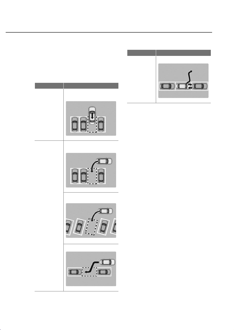
7-147
07
5(027(60$573$5.,1*$66,67Ƀʚ563$Ƀʛ
Remote Smart Parking Assist uses
vehicle sensors to help the driver park
and exit parking spaces remotely from
outside the vehicle by controlling the
steering wheel, vehicle speed, and
gearshifts.
Function Description
Remote
Operation
Remotely moving forward
or backward
ORS071079
ORS071079
Smart
Parking or
Remote
Smart
Parking
Perpendicular reverse
parking
ORS071080
ORS071080
Diagonal reverse parking
ORS071081
ORS071081
Parallel reverse parking
ORS071190
ORS071190
Function Description
Smart Exit
Parallel forward exit
ORS072082N
ORS072082N
• Remote Smart Parking and Remote
Operation function may be operated
from outside the vehicle using the
smart key.
• Smart Parking and Remote Smart
Parking function may be operated
from inside the vehicle.
• Smart Parking and Remote Smart
Parking function helps the driver
with perpendicular reverse parking,
diagonal reverse parking and parallel
reverse parking.
• Smart Exit function helps the driver
with parallel forward exit.
• When Remote Smart Parking Assist
operates, Parking Distance Warning
and Surround View Monitor will also
operate. For more details, refer to
“Parking Distance Warning (PDW)”
and “Surround View Monitor (SVM)”
sections in this chapter.
• Remote Smart Parking Assist helps
parking by recognizing the parking
lines with the wide view camera.
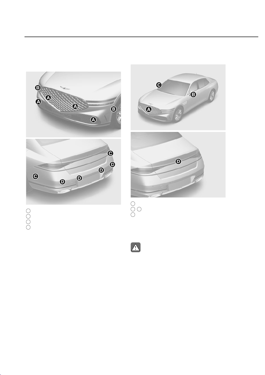
7-148
Driver Assistance System
Detecting Sensors
Ultrasonic sensors
ORS071014
ORS071014
ORS072017N
ORS072017N
A
: Front ultrasonic sensors,
B
: Front side ultrasonic sensors,
C
: Rear side ultrasonic sensor,
D
: Rear ultrasonic sensor
Refer to the picture above for the
detailed location of the detecting
sensors.
Wide view camera
ORS071140
ORS071140
ORS071141
ORS071141
A
: Wide-front view camera,
B
,
C
: Wide-side view camera,
D
: Wide-rear view camera
Refer to the picture above for the
detailed location of the detecting
sensors.
CAUTION
Take the following precautions to
maintain optimal performance of the
detecting sensors:
• 1HYHUGLVDVVHPEOHWKHGHWHFWLQJ
VHQVRURUVHQVRUDVVHPEO\RUFDXVH
DQ\GDPDJHWRLW
• ,IWKHGHWHFWLQJVHQVRUVQHHGUHSDLU
KDYH\RXUYHKLFOHLQVSHFWHGE\
DQDXWKRUL]HGUHWDLOHURI*HQHVLV
%UDQGHGSURGXFWV
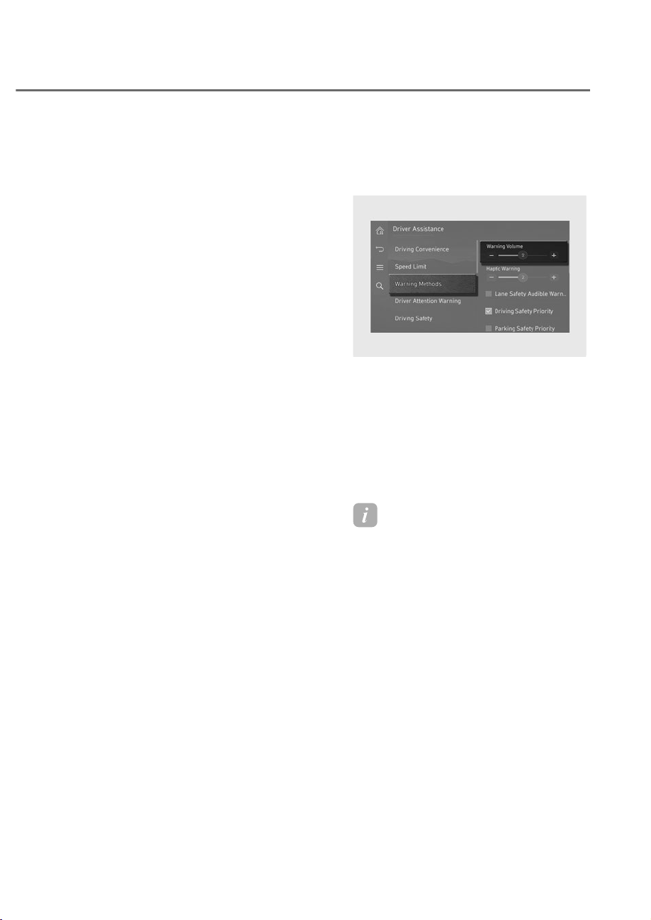
7-149
07
• 5HPRWH6PDUW3DUNLQJ$VVLVW
PD\PDOIXQFWLRQLIWKHYHKLFOH
EXPSHUKHLJKWRUXOWUDVRQLFVHQVRU
LQVWDOODWLRQKDVEHHQPRGLILHG
RUGDPDJHG$Q\QRQIDFWRU\
LQVWDOOHGHTXLSPHQWRUDFFHVVRULHV
PD\DOVRLQWHUIHUHZLWKWKHVHQVRU
SHUIRUPDQFH
• :KHQWKHXOWUDVRQLFVHQVRULVIUR]HQ
RUVWDLQHGZLWKVQRZGLUWRUZDWHU
WKHVHQVRUPD\EHQRWRSHUDWHXQWLO
WKHVWDLQVDUHUHPRYHGXVLQJDVRIW
FORWK
• 'RQRWSXVKVFUDWFKRUVWULNHWKH
XOWUDVRQLFVHQVRU6HQVRUGDPDJH
FRXOGRFFXU
• 'RQRWVSUD\WKHXOWUDVRQLFVHQVRUV
RULWVVXUURXQGLQJDUHDGLUHFWO\ZLWK
DKLJKSUHVVXUHZDVKHU
• $OZD\VNHHSWKHFDPHUDOHQVFOHDQ
,IWKHOHQVLVFRYHUHGZLWKIRUHLJQ
PDWHULDOLWPD\DGYHUVHO\DIIHFW
camera performance and Remote
6PDUW3DUNLQJ$VVLVWPD\QRWRSHUDWH
SURSHUO\
• 'RQRWPDQXDOO\DGMXVWWKHUHDUYLHZ
PLUURURUXVH5HPRWH6PDUW3DUNLQJ
Assist after a hard impact on the side
YLHZPLUURU
When a collision occurs or the side
YLHZPLUURULVPDQXDOO\RSHUDWHG
5HPRWH6PDUW3DUNLQJ$VVLVWPD\QRW
RSHUDWHSURSHUO\
5HPRWH6PDUW3DUNLQJ$VVLVW
Settings
Warning methods
ORS073337N
ORS073337N
With the engine on, go to 'Driver
$VVLVWDQFHɌ:DUQLQJ0HWKRGVIURPWKH
Settings in the infotainment system to
select the following:
• Warning Volume: The warning volume
can be adjusted. If you turn off the
Warning Volume, for your safety, the
function may warn you with a low
volume.
Information
• If you change the Warning Methods,
Warning Methods of other Driver
Assistance systems may change.
• Warning Method will maintain its last
setting even if the vehicle is restarted.
• The setting menu may not be available
for your vehicle depending on the
vehicle features and specifications.
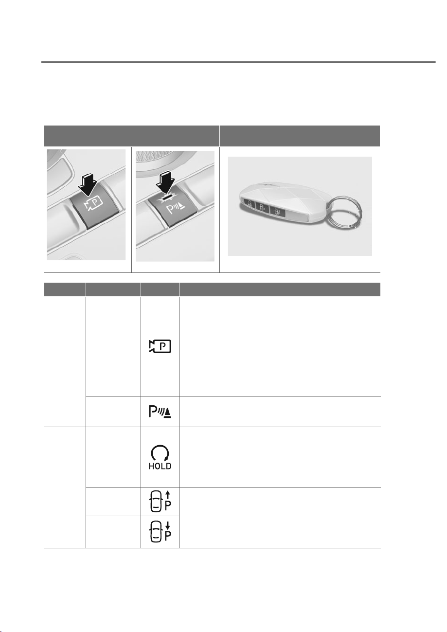
7-150
Driver Assistance System
5HPRWH6PDUW3DUNLQJ$VVLVW2SHUDWLRQ
Remote Smart Parking Assist button
3DUNLQJ9LHZEXWWRQ3DUNLQJ6DIHW\EXWWRQ 6PDUWNH\
ORS071142
ORS071142
ORS071019
ORS071019
ORS071037
ORS071037
Location Name 6\PERO Description
Inside
vehicle
Parking/View
button
• Press and hold the Parking/View button to turn
on Remote Smart Parking Assist. Also, Forward/
Reverse Parking Distance warning will automatically
turn on.
However, functions may differ depending on the
situations. Refer to each function's description for
more details in the following pages.
• Press and hold the Parking/View button while Smart
Parking or Smart Exit function is on to operate the
function.
Parking
Safety button
• Press the Parking Safety button while Remote Smart
Parking Assist is operating to end Remote Smart
Parking Assist operation.
Smart
key
Remote Start
button
• Press the Remote Start button after the door is
locked with the engine off to start the engine
remotely.
• Press the Remote Start button while Remote Smart
Parking or Remote Operation function is operating
to end function operation.
Forward
button
• When using Remote Smart Parking function,
regardless of which direction button is pressed,
parking is supported while the button is pressed.
• When using the Remote Operation function, the
vehicle moves in the direction of the button while
the button is pressed.
Backward
button
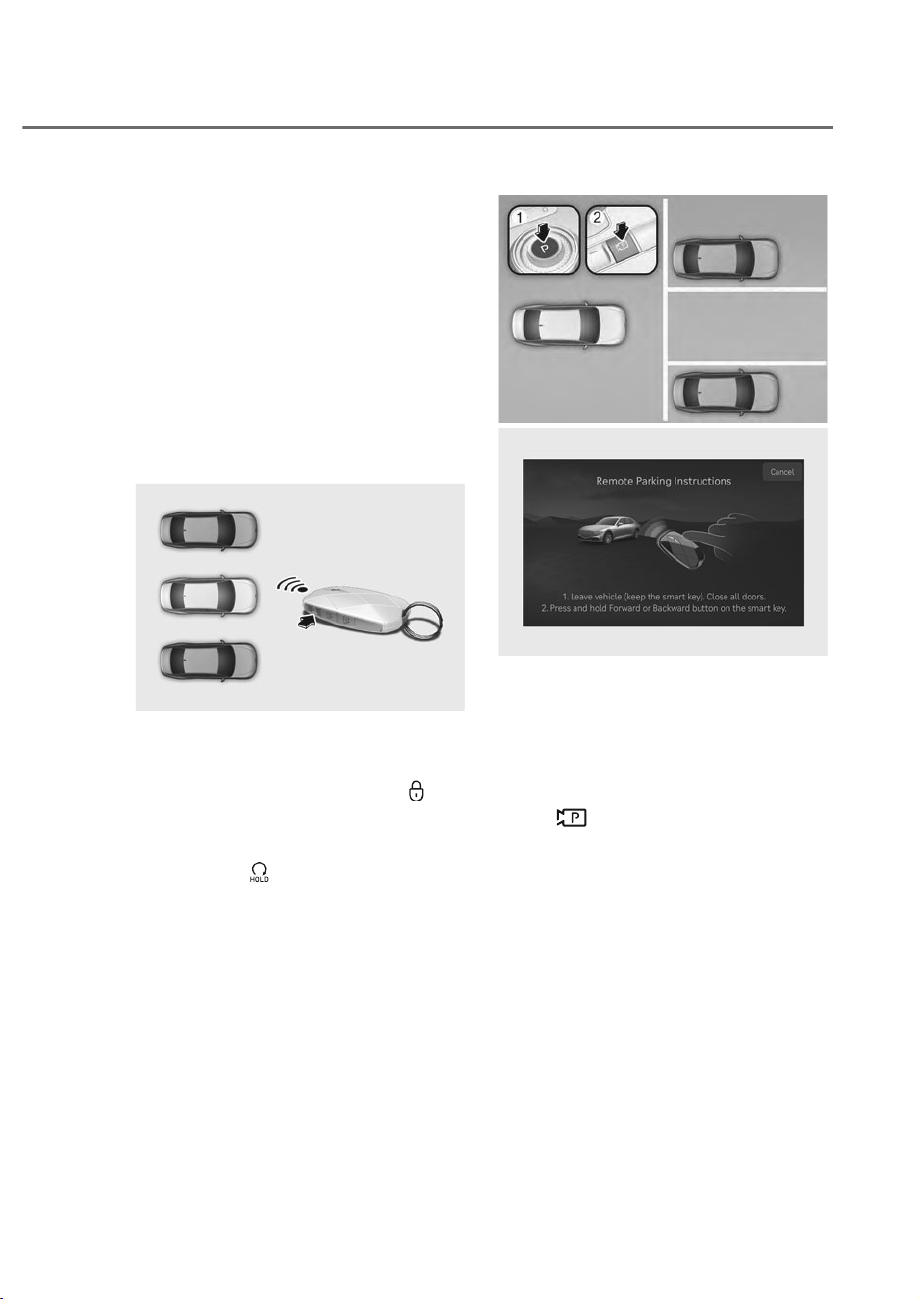
7-151
07
Remote Operation
perating order
Remote Operation functions in the
following order:
1. Getting ready to remotely move
forward and backward
2. Remotely moving forward and
backward
ȸ*HWWLQJUHDG\WRUHPRWHO\PRYHIRUZDUG
DQGEDFNZDUG
There are two ways to operate Remote
Operation function.
ORS071136
ORS071136
Method (1) Using the function with
engine off
(1) Within a certain range from the
vehicle press the door lock (
)
button on the smart key and lock
all doors.
(2) Press and hold the Remote Start
button (
) within 4 seconds until
the engine starts.
For more details on remotely
starting the engine, refer to
“Remote Start” section in chapter
6.
ORS071075
ORS071075
ORS071164L
ORS071164L
Method (2) Using the function with
engine on
(1) Park the vehicle in front of the
space where you want to use
Remote Operation function, and
shift the gear to P (Park).
(2) Press and hold the Parking/View
(
) button to turn on Smart
Parking Assist. A message ‘Remote
Parking Instructions’ will appear
on the infotainment system
screen.
(3) Get out of the vehicle with the
smart key and close all doors.
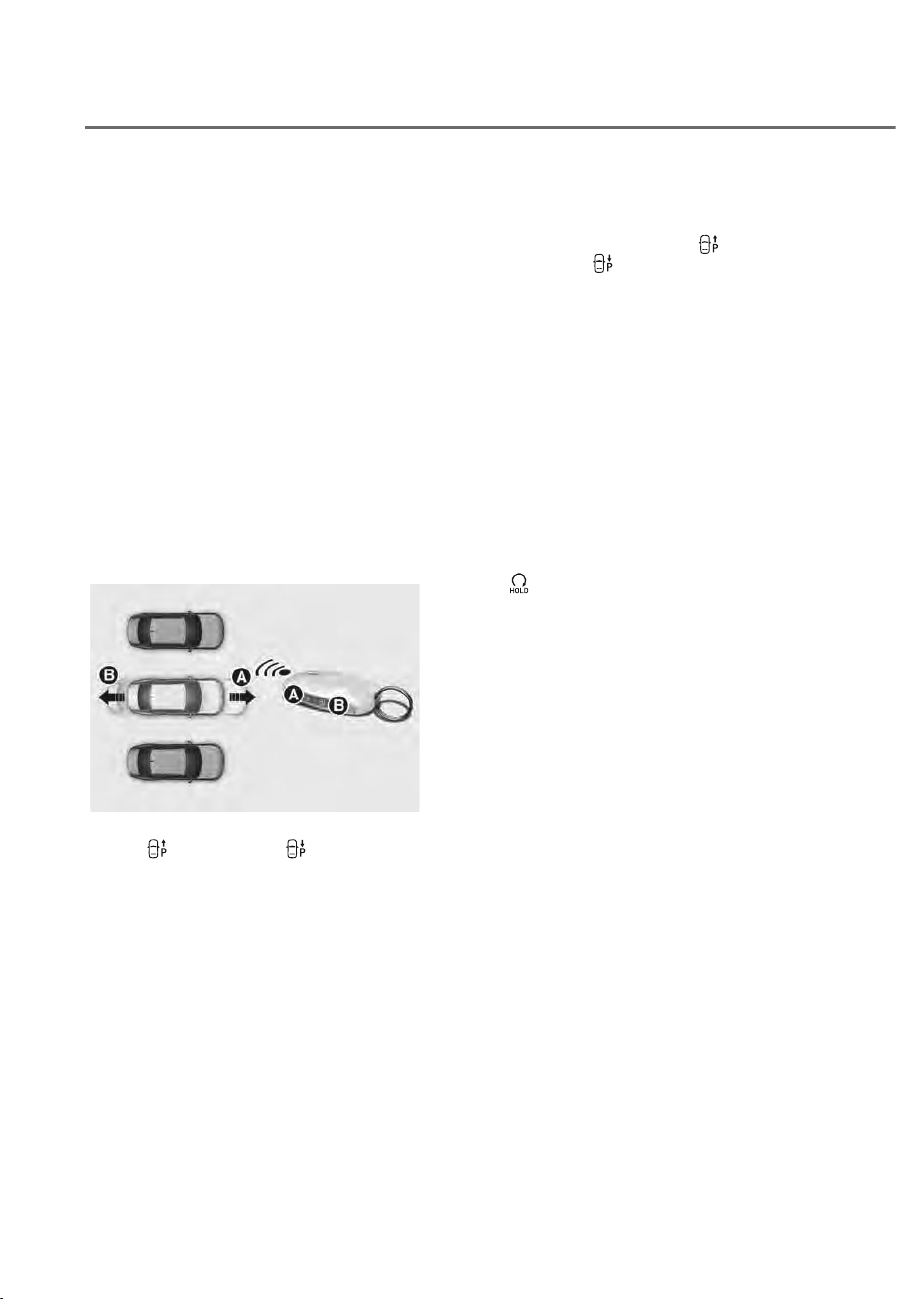
7-152
Driver Assistance System
• 'Agree' must be selected on the
infotainment system screen and the
infotainment system has to operate
properly to use Remote Operation
function.
• Method (2) can be used after the
vehicle has been driven above 3
mph (5 km/h).
• If the function is turned on again
after parking is completed by
Remote Smart Parking Assist,
Remote Operation function can be
used with Method (2).
• Check that all smart keys are
outside the vehicle when using
Remote Operation function.
ȹ5HPRWHO\PRYLQJIRUZDUGDQG
EDFNZDUG
ORS071036
ORS071036
(1) Press and hold one of the Forward
(
) or Backward ( ) button on
the smart key. Remote Smart
Parking Assist will automatically
control the steering wheel, vehicle
speed and gearshift. The vehicle
will move in the direction of the
button pressed.
(2) While Remote Operation function
is operating, if you do not
hold down the Forward (
) or
Backward (
) button, the vehicle
will stop and function control
will pause. The function will start
operating again when the button is
pressed and held again.
(3) When the vehicle reaches the
target location, release the smart
key Forward or Backward button.
(4) When the driver gets in the vehicle
with the smart key, a message
will appear informing the driver
Remote Operation function is
complete on the infotainment
system screen and the engine will
remain on.
In addition, when the Remote Start
(
) button is pressed on the smart
key from outside the vehicle, a
message will appear informing the
driver Remote Operation function
is complete and the engine will
turn off.

7-153
07
Information
• heck that all smart keys are outside
the vehicle when using Remote
peration function.
• Remote peration function will operate
only when the smart key is within
13 ft. (4 m) from the vehicle. If there
is no vehicle movement even when
the Forward or Backward button is
pressed on the smart key, check the
distance to the vehicle and press the
button again.
• The detecting range of the smart
key may vary depending on the
surroundings that are affected by radio
waves such as transmission tower,
broadcast station, etc.
• When remotely moving forward using
method (1), it is recognized as an exit
situation, and the vehicle moves 13
ft. (4 m) to check for parking lines,
pedestrians, animals or ob ects around
the vehicle. After confirmation, the
steering wheel is controlled according
to the condition ahead.
• When remotely moving forward
using method (2), it is recognized as a
parking situation, and will immediately
control the steering wheel according
to the condition ahead to assist with
entering the parking space and aligning
the vehicle. However, performance may
reduce depending on the parking lines
pedestrians, animals, shape of ob ects,
location, etc., around the vehicle.
• For moving remotely backward, both
method (1) and (2) aligns the steering
wheel first, and then will only move the
vehicle straight.
• When remotely moving forward or
backward is completed, the vehicle
will automatically shift to P (Park)
and engage EPB (Electronic Parking
Brake).
CAUTION
• When using Remote Operation
IXQFWLRQPDNHVXUHWKDWDOO
SDVVHQJHUVKDYHJRWWHQRXWRIWKH
YHKLFOH
• ,IWKHYHKLFOHȂVEDWWHU\LVGLVFKDUJHG
RU5HPRWH6PDUW3DUNLQJ$VVLVW
malfunctions when parked in a
QDUURZSDUNLQJVSDFH5HPRWH
2SHUDWLRQIXQFWLRQZLOOQRWRSHUDWH
$OZD\VSDUN\RXUYHKLFOHLQDVSDFH
ZLGHHQRXJKIRU\RXWRJHWLQRURXW
RI\RXUYHKLFOH
• 'HSHQGLQJRQWKHSDUNLQJVSDFH
\RXPD\QRWEHDEOHWRH[LWIURPWKH
VSDFH\RXKDYHHQWHUHGE\XVLQJ
5HPRWH2SHUDWLRQIXQFWLRQ
• $IWHUSDUNLQJWKHVXUURXQGLQJPD\
FKDQJHGXHWRWKHPRYHPHQWRI
VXUURXQGLQJYHKLFOHV,IWKLVRFFXUV
5HPRWH2SHUDWLRQIXQFWLRQPD\QRW
RSHUDWH
• %HIRUHOHDYLQJWKHYHKLFOHFORVH
ZLQGRZVDQGVXQURRIVDQGPDNH
VXUHWKHHQJLQHLVRIIEHIRUHORFNLQJ
WKHGRRUV

7-154
Driver Assistance System
Remote peration function operation
status
Operation
status
6PDUWNH\/('
+D]DUG
warning
light
Under
control
Green LED
continuously
blinks
-
Pause
Red LED
continuously
blinks
Blinks
Off
Red LED
illuminates for
4 seconds and
then turns off
Blinks 3
times and
turns off
Complete
Green LED
illuminates for
4 seconds and
then turns off
Blinks 1
time and
turns off
à Operation status by the hazard
warning light may not be applicable
based on the regulation of your
country.
à If the smart key is not within the
operating range from the vehicle
(approximately 13 ft. (4 m)), the
smart key LED will not illuminate or
blink. Use the smart key within the
operating range.
How to turn off Remote peration
function while operating
• Press the Parking/View ( ) button
while the infotainment system screen
guides the driver using method 2.
• Shift the gear from P (Park) to any
other position while the infotainment
system screen guides the driver using
method 2.
• Press the Parking Safety ( ) button
or select ‘Cancel’ on the infotainment
system screen.
• Press the Remote Start (
) button
on the smart key while the vehicle is
being controlled by Remote Operation
function. Remote Operation function
will turn off. At this time, the engine
will turn off.
• Get on the vehicle with the smart key.
Remote Operation function will turn
off. At this time, the engine will remain
on.

7-155
07
The function will pause in the following
conditions when:
• There is a pedestrian, animal or object
in the direction the vehicle is moving
• The door or trunk is open
• The Forward (
) or Backward ( )
button is not continuously pressed
• Simultaneously pressing multiple
buttons on a smart key
• The smart key is not operated within
13 ft. (4 m) from the vehicle
• Button of another smart key is pressed
in addition to the operating smart key
• Blind-Spot Collision-Avoidance
Assist or Rear Cross-Traffic Collision-
Avoidance Assist operates while the
vehicle is being controlled in the
reverse direction.
• The vehicle moves 22 ft. (7 m) while
the smart key is pressed with Remote
Operation function (maximum travel
distance per button press)
When Remote operation function is
paused, the vehicle will stop. If the
condition that made the function to
pause disappears, the function may
operate again.
The function will cancel in the following
conditions when:
• The steering wheel is steered
• The gear is shifted while the vehicle is
moving
• Operating EPB while the vehicle is
moving
• The hood is open
• The brake pedal or accelerator pedal
is depressed when all the doors are
closed
• The smart key is outside the vehicle
when the brake pedal is depressed
while the driver's door is open
• Rapid acceleration occurs
• Vehicle skid occurs
• The wheel is stuck by an obstacle and
cannot move
• Approximately 3 minutes and 50
seconds have past after Remote
Operation function has started to
operate
• The slope of the road exceeds the
operational range
• The function is paused for more than
1 minute
• The total travel distance of the vehicle
has exceeded 45 ft. (14 m) after
Remote Operation function operation
• The steering wheel, gearshift, braking,
and drive controls are not working
properly
• There is a problem with the smart key
or the smart key battery is low
• ABS, TCS or ESC system operates due
to slippery road conditions
• The alarm of the Theft Alarm System
sounds
When Remote Operation function is
canceled, the vehicle will automatically
stop, shift the gear to P (Park) and
engage EPB (Electronic Parking Brake).
The engine will turn off.
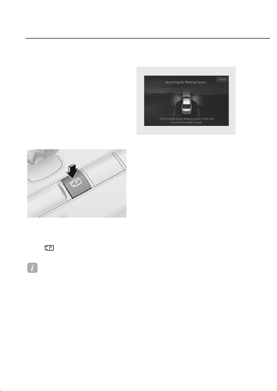
7-156
Driver Assistance System
Smart Parking, Remote Smart
Parking
perating order
Parking function operates in the
following order:
1. Getting ready for parking
2. Searching for parking space
3. Select parking type and operating
mode
4. Smart Parking
5. Remote Smart Parking
ȸ*HWWLQJUHDG\IRUSDUNLQJ
ORS071142
ORS071142
(1) With the engine turned on,
depress the brake pedal and shift
the gear to D (Drive) or N (Neutral).
(2) Press and hold the Parking/View
(
) button to turn on Remote
Smart Parking Assist.
Information
• 'Agree' must be selected on the
infotainment system screen and the
infotainment system has to operate
properly to use Parking function.
• If you drive above 3 mph (5 km/h) with
the engine on, you may use the Parking
function with the gear shifted to N
(Neutral).
ȹ6HDUFKLQJIRUSDUNLQJVSDFH
ORS071275L
ORS071275L
(1) Slowly drive forward maintaining
the distance of approximately 40
in. (100 cm) from the parking lines
or the parked vehicles.
(2) When searching for a parking
space is complete, a message will
appear on the infotainment system
screen with an audible sound to
notify the search is complete.
(3) ‘Select Parking Type’ will be
displayed on the infotainment
system screen and the selected
parking space will appear on Top
View screen of Surround View
Monitor.
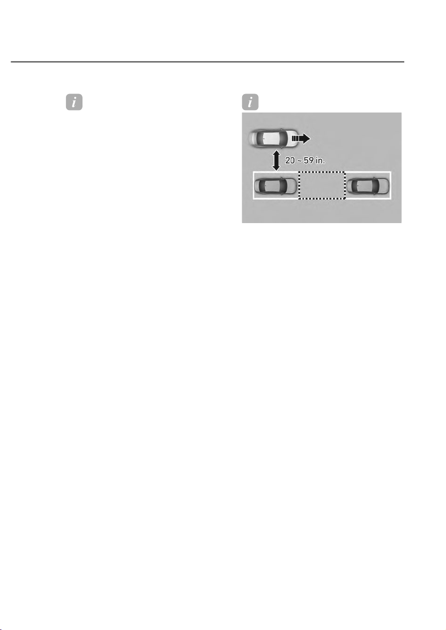
7-157
07
Information
• Remote Smart Parking Assist searches
parking lines or parking spaces that are
next to parked vehicles. Remote Smart
Parking Assist cannot search parking
spaces in front or rear of the vehicle.
• While searching for a parking space,
when vehicle speed is above 12 mph (20
km/h), a message will appear on the
infotainment system screen informing
you to slow down. When vehicle speed
is above 18 mph (30 km/h), Parking
function will turn off.
• Searching for a parking space will be
completed when there is enough space
to move the vehicle in addition to the
parking space.
• Even if an audible sound is heard to
notify that searching for a parking
space is complete, search completion
can be canceled immediately depending
on surroundings.
Information
ORS072035N
ORS072035N
• If the distance is below 20 in. (50 cm)
or over 59 in. (150 cm), Remote Smart
Parking Assist may not be able to
search for a parking space.
• If you do not maintain a certain
distance from the parked vehicle, the
performance to search for a parking
space may reduce.
• Due to abnormal performance of the
ultrasonic sensor or the influence of
the surroundings, Parking function
may not be able to search for a parking
space even if there is a parking space,
or may search for a space that is not
suitable for parking.
• If the parking space is on a incline or
is diagonal, the parking type displayed
may be different from the actual
parking type which should be selected.
If this occurs, do not select the parking
type, and search for another parking
space.
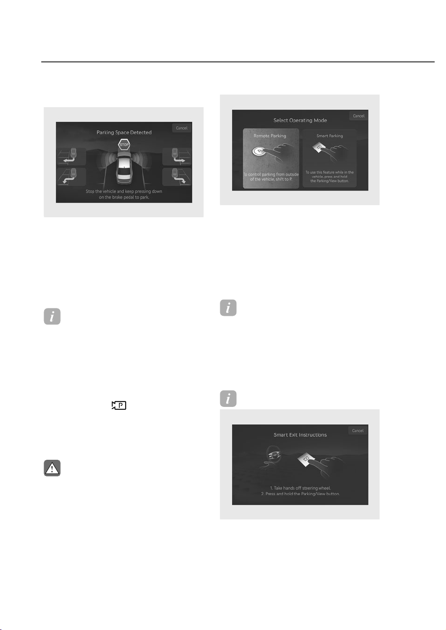
7-158
Driver Assistance System
Ⱥ6HOHFWSDUNLQJW\SHDQGRSHUDWLQJPRGH
ORS071276L
ORS071276L
(1) Parking type – Perpendicular
reverse (Left/Right), Parallel
reverse (Left/Right)
With the vehicle stopped by
depressing the brake pedal, touch
the infotainment system screen or
use the central controller to select
the desired parking type.
Information
• If you continue to drive without
stopping after the parking type
selection screen appears, Remote
Smart Parking Assist will return to the
previous stage and search for a parking
space.
• If Parking function is canceled
unintentionally by pressing the
Parking/ iew (
) button before the
parking type is selected, you can return
to the parking type selection stage by
pressing and holding the button again
while the vehicle is stopped.
CAUTION
%HIRUHVHOHFWLQJWKH3DUNLQJW\SH
WKHGULYHUVKRXOGFKHFNZKHWKHUWKH
SDUNLQJVSDFHLVVXLWDEOH
,IWKHVHDUFKHGSDUNLQJVSDFHE\
5HPRWH6PDUW3DUNLQJ$VVLVWLVQDUURZ
RUXQVXLWDEOHIRUSDUNLQJGRQRWVHOHFW
WKH3DUNLQJW\SHDQGPRYHWKHYHKLFOH
WRVHDUFKIRUDQRWKHUSDUNLQJVSDFH
ORS071277L
ORS071277L
(2) Operating mode – Remote
Parking, Smart Parking
After selecting a parking type,
the infotainment system screen
will guide you with Remote Smart
Parking function and Smart
Parking function. Follow the
instructions to operate Remote
Smart Parking Assist.
Information
• perating instructions will be
displayed on the screen for each desired
function you select.
• Do not take your foot off the brake
pedal during the Parking function
guide. When the vehicle moves, Remote
Smart Parking Assist will turn off.
Information
ORS071278L
ORS071278L
If Remote Smart Parking Assist cannot
activate Remote Smart Parking function,
only the Smart Parking guide will be
displayed on the infotainment system
screen.
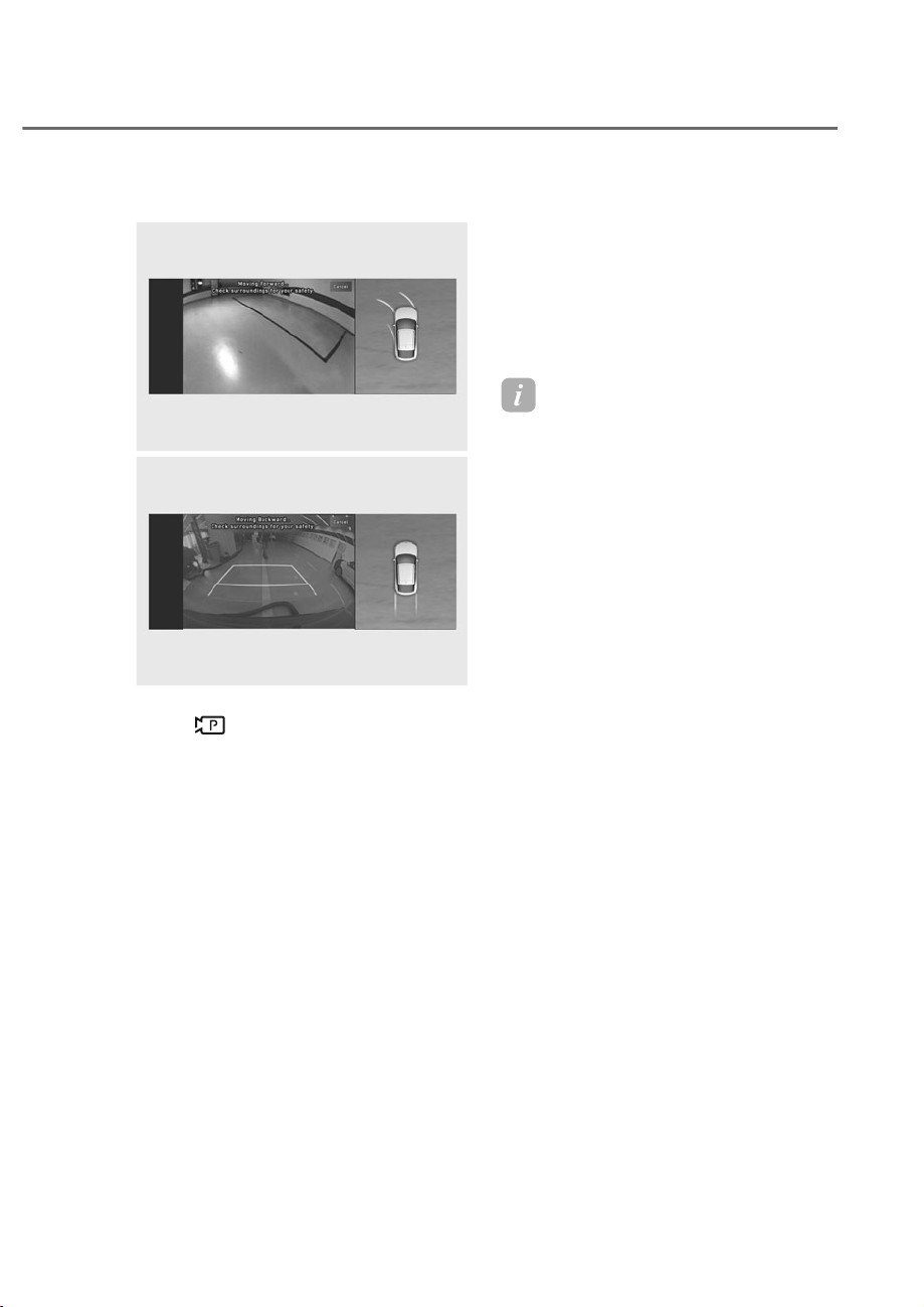
7-159
07
Ȼ6PDUW3DUNLQJ
OJWEV071226L
OJWEV071226L
OJWEV071227L
OJWEV071227L
(1) Press the Parking/View
(
) button when the vehicle is
stopped by depressing the brake
pedal. When the brake pedal is
released, Remote Smart Parking
Assist will automatically control
the steering wheel, vehicle speed
and gearshift.
(2) While Smart Parking function
is operating, if you do not hold
down the Parking/View button,
the vehicle will stop and function
control will pause. The function
will start operating again when the
Parking/View button is pressed
and held again.
(3) When the vehicle reaches the
target parking position, a message
will appear on the infotainment
system screen to inform you that
parking is complete.
(4) If you need to change the vehicle’s
position or location, manually
complete parking your vehicle.
Information
• Smart Parking function will not
operate if the door is open or the seat
belt is not fastened.
• The parking location indicator is
displayed on Surround iew Monitor
screen and is displayed until the vehicle
enters the parking space for the first
time by Smart Parking function.
• ehicle speed can be ad usted by
depressing the brake pedal while Smart
Parking function is operating. However,
the vehicle does not accelerate
even when the accelerator pedal is
depressed.
• Depending on parking environments,
if the vehicle is stopped by a stopper,
parking may be completed.
• If you need to change the vehicle's
position or location, manually complete
parking your vehicle.

7-160
Driver Assistance System
ȼ5HPRWH6PDUW3DUNLQJ
ORS071164L
ORS071164L
(1) Shift the gear to P (Park), get out
of the vehicle with the smart key,
and close all doors.
(2) Press and hold one of the Forward
(
) or Backward ( ) button on
the smart key. Remote Smart
Parking Assist will automatically
control the steering wheel, vehicle
speed and gearshift.
(3) While Remote Smart Parking
function is operating, if you do
not hold down the Forward (
) or
Backward (
) button, the vehicle
will stop and function control
will pause. The function will start
operating again when the button is
pressed and held again.
(4) When the vehicle reaches the
target parking position, a message
will appear on the infotainment
system screen to inform you that
parking is complete. The vehicle
will automatically shift to P (Park),
engage EPB (Electronic Parking
Brake) and the engine will turn off.
(5) If you need to change the vehicle’s
position or location, manually
complete parking your vehicle.
Information
• When operating Remote Smart
Parking function, make sure all smart
keys are outside of the vehicle.
• Remote Smart Parking function will
operate only when the smart key is
within 13 ft. (4 m) from the vehicle. If
there is no vehicle movement even when
the Remote Forward or Backward
button is pressed on the smart key,
check the distance to the vehicle and
press the button again.
• The detecting range of the smart
key may vary depending on the
surroundings that are affected by radio
waves such as transmission tower,
broadcast station, etc.
• The parking location indicator is
displayed on Surround iew Monitor
screen and is displayed until the
vehicle enters the parking space for the
first time by Remote Smart Parking
function.
• Depending on parking environments,
if the vehicle is stopped by a stopper,
parking may be completed.
CAUTION
• :KHQXVLQJ5HPRWH6PDUW3DUNLQJ
IXQFWLRQPDNHVXUHWKDWDOO
SDVVHQJHUVKDYHJRWWHQRXWRIWKH
YHKLFOH
• After ending or turning off Remote
6PDUW3DUNLQJIXQFWLRQEHIRUH
OHDYLQJWKHYHKLFOHFORVHZLQGRZV
DQGVXQURRIVDQGPDNHVXUHWKH
HQJLQHLVRIIEHIRUHORFNLQJWKH
GRRUV

7-161
07
Parking function operation status
• Smart Parking function
Operation status Turn signal
Under control
The turn signal of the parking direction blinks until the first reverse
is complete.
• Remote Smart Parking function
Operation status 6PDUWNH\/(' +D]DUGZDUQLQJOLJKW Turn signal
Under control
Green LED
continuously blinks
-
The turn signal of
the parking direction
blinks until the first
reverse is complete.
Pause
Red LED
continuously blinks
Blinks -
Off
Red LED illuminates
for 4 seconds and
then turns off
Blinks 3 times and
turns off
-
Complete
Green LED
illuminates for 4
seconds and then
turns off
Blinks 1 time and
turns off
-
à Operation status by the hazard warning light and turn signal may not be applicable
based on the regulation of your country.
à If the smart key is not within the operating range from the vehicle (approximately 13
ft. (4 m)), the smart key LED will not illuminate or blink. Use the smart key within the
operating range.

7-162
Driver Assistance System
The function will pause in the
following conditions when:
• Smart Parking
- There is a pedestrian, animal or
object in the direction the vehicle is
moving
- The door or trunk is open
- The driver’s seat belt is not fastened
- Blind-Spot Collision-Avoidance
Assist or Rear-Cross Traffic
Collision-Avoidance Assist operates
while the vehicle is being controlled
in the reverse direction
- The Parking/View (
) button is
not continuously pressed
- The vehicle is stopped by
depressing the brake pedal
• Remote Smart Parking
- There is a pedestrian, animal or
object in the direction the vehicle is
moving
- The door or trunk is open
- The Forward ( ) or Backward ( )
button is not continuously pressed
- Simultaneously pressing multiple
buttons on a smart key
- The smart key is not operated within
13 ft. (4 m) from the vehicle
- Button of another smart key is
pressed in addition to the operating
smart key
- Blind-Spot Collision-Avoidance
Assist or Rear-Cross Traffic
Collision-Avoidance Assist, or
Parking Collision-Avoidance Assist
operates.
When Parking function is paused, the
vehicle will automatically stop. If the
condition that made the function to
pause disappears, the function may
operate again.
How to turn off Parking function
while operating
• Press the Parking/View ( ) button
in the following stage:
- Searching for parking space
- Select parking type
• Shift the gear to R (Reverse) in the
following stage:
- Searching for parking space
- Select parking type
- Select operating mode
• Press the Parking Safety ( ) button
or select ‘Cancel’ on the infotainment
system screen to turn off Parking
function.
• While Smart Parking function is
operating:
- If the vehicle is stopped by
depressing the brake pedal, and the
gear is shifted, Parking function will
turn off. At this time, EPB (Electronic
Parking Brake) will not be engaged.
• While Remote Smart Parking function
is operating:
- Press the Remote Start (
) button
on the smart key. Parking function
will turn off.
- Get on the vehicle with the smart
key. Parking function will turn off. At
this time, the engine will remain on.

7-163
07
The function will cancel in the
following conditions when:
• Smart Parking
- The steering wheel is steered
- The gear is shifted while the vehicle
is moving
- Operating EPB while the vehicle is
moving
- The hood is open
- The driver opens the door with the
seatbelt unfastened
- Rapid acceleration occurs
- Vehicle skid occurs
- The wheel is stuck by an obstacle
and cannot move
- There are pedestrians, animals or
objects at the front and rear of the
vehicle at the same time
- Approximately 3 minutes and 50
seconds have past after Smart
Parking function has started to
operate
- The slope of the road exceeds the
operational range
- The function is paused for more
than 1 minute
- The steering wheel, gearshift,
braking, and drive controls are not
working properly
- ABS, TCS or ESC system operates
due to slippery road conditions
When Smart Parking function is
canceled, the vehicle will automatically
stop, shift the gear to P (Park) and
engage EPB (Electronic Parking Brake).
• Remote Smart Parking
- The steering wheel is steered
- The gear is shifted
- Operating EPB while the vehicle is
moving
- The hood is open
- The brake pedal or accelerator
pedal is depressed when all the
doors are closed
- The smart key is outside the vehicle
when the brake pedal is depressed
while the driver's door is open.
- Rapid acceleration occurs
- Vehicle skid occurs
- The wheel is stuck by an obstacle
and cannot move
- There are pedestrians, animals or
objects at the front and rear of the
vehicle at the same time
- Approximately 3 minutes and 50
seconds have past after Remote
Smart Parking function has started
to operate
- The slope of the road exceeds the
operational range
- The function is paused for more
than 1 minute
- The steering wheel, gearshift,
braking, and drive controls are not
working properly
- There is a problem with the smart
key or the smart key battery is low
- ABS, TCS or ESC system operates
due to slippery road conditions
- The alarm of the Theft Alarm System
sounds
When Remote Smart Parking function is
canceled, the vehicle will automatically
stop, shift the gear to P (Park) and
engage EPB (Electronic Parking Brake).
The engine will turn off.
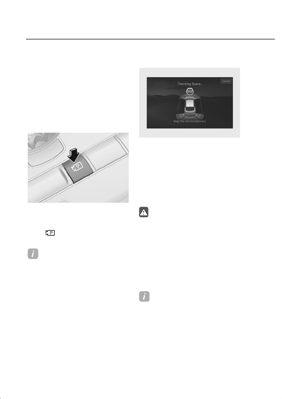
7-164
Driver Assistance System
Smart Exit
perating order
Smart Exit function operates in the
following order:
1. Getting ready for exit
2. Checking space
3. Select exit direction
4. Smart Exit
ȸ*HWWLQJUHDG\IRUH[LW
ORS071142
ORS071142
(1) With the engine turned on,
depress the brake pedal and shift
the gear to P (Park) or N (Neutral).
(2) Press and hold the Parking/View
(
) button to turn on Remote
Smart Parking Assist.
Information
• 'Agree' must be selected on the
infotainment system screen and the
infotainment system has to operate
properly to use Smart Smart Exit
function.
• Drive below 3 mph (5 km/h) with
the engine on and shift the gear to N
(Neutral), Smart Exit function can be
used.
• If the function is turned on again
after parallel parking is completed by
Remote Smart Parking Assist, Smart
Exit function can be used.
ȹ&KHFNLQJVSDFH
ORS071279L
ORS071279L
(1) When the vehicle is stopped by
depressing the brake pedal, the
vehicle sensors will detect the
distance from nearby objects and
check for space to exit.
(2) When checking for space is
complete, a message will appear
on the infotainment system screen
with an audible sound to notify the
search is complete.
WARNING
• :KLOHFKHFNLQJIRUVSDFHLIWKHUHLV
DULVNRIFROOLVLRQZLWKSHGHVWULDQ
DQLPDORUREMHFWLQWKHGLUHFWLRQRI
YHKLFOHH[LWIRU\RXUVDIHW\6PDUW
([LWIXQFWLRQFDQEHWXUQHGRII
• (YHQLIFKHFNIRUVSDFHLVFRPSOHWHG
REMHFWVLQWKHEOLQGVSRWDUHDFDQQRW
EHGHWHFWHGE\WKHVHQVRUV7KH
GULYHUPXVWGLUHFWO\FKHFNWKHEOLQG
spot area and continue using the
IXQFWLRQ
Information
Due to abnormal performance of the
ultrasonic sensor or the influence of the
surroundings, Parking function may not
be able to search for an exit space even if
there is a an exit space, or may search for
a space that is not suitable for exiting.
- The parked vehicle has ob ects attached
to the bumper such as bumper guard,
trailer hitch, etc.

7-165
07
Ⱥ6HOHFWH[LWGLUHFWLRQ
ORS071280L
ORS071280L
(1) With the vehicle stopped by
depressing the brake pedal, the
infotainment system screen
displays the possible directions for
parallel exit.
(2) Touch the infotainment system
screen or use the central controller
to select the desired exit direction.
CAUTION
• %HIRUHVHOHFWLQJWKH([LW'LUHFWLRQ
WKHGULYHUVKRXOGFKHFNZKHWKHUWKH
VSDFHIRUH[LWLVVXLWDEOH
• ,IWKHVHDUFKHGH[LWVSDFHE\5HPRWH
6PDUW3DUNLQJ$VVLVWLVQDUURZRU
XQVXLWDEOHVXUURXQGLQJYHKLFOHVDUH
SDUNHGYHUWLFDOO\HWFGRQRWXVH
WKH6PDUW([LWIXQFWLRQ
Ȼ6PDUW([LW
ORS071278L
ORS071278L
(1) Press the Parking/View
(
) button when the vehicle is
stopped by depressing the brake
pedal. When the brake pedal is
released, Remote Smart Parking
Assist will automatically control
the steering wheel, vehicle speed
and gearshift.
(2) While Smart Exit function is
operating, if you do not hold
down the Parking/View button,
the vehicle will stop and function
control will pause. The function
will start operating again when the
Parking/View button is pressed
and held again.
(3) When the vehicle reaches the
target exit location, a message will
appear on the infotainment system
screen to inform you that exit is
complete.

7-166
Driver Assistance System
Information
• Smart Exit function will not operate
if the door is open or the seat belt is
not fastened.
• ehicle speed can be ad usted by
depressing the brake pedal while
Smart Exit function is operating.
However, the vehicle does not
accelerate even when the accelerator
pedal is depressed.
• If exit is completed while depressing
the brake pedal, Smart Exit function
will complete with the gear in D
(Drive).
• If exit is completed while depressing
the accelerator pedal, you must take
your foot off the accelerator pedal
once for the accelerator pedal to
operate.
• If there is no vehicle operation such
as depressing the brake pedal or
accelerator pedal within 4 seconds
after exit is complete, the vehicle
will automatically shift to P (Park)
and engage EPB (Electronic Parking
Brake).
• After Exit function is complete,
always check the surroundings before
driving.
Smart Exit operation status
Operation
status
Turn signal
Under
control
The turn signal of the exit
direction blinks until the exit
is complete or Smart Exit is
canceled.
The function will pause in the following
conditions when:
• There is a pedestrian, animal or object
in the direction the vehicle is moving
• The door or trunk is open
• The driver’s seat belt is not fastened
• Blind-Spot Collision-Avoidance
Assist or Rear-Cross Traffic Collision-
Avoidance Assist operates while the
vehicle is being controlled in the
reverse direction
• The Parking/View (
) button is not
continuously pressed
• The vehicle is stopped by depressing
the brake pedal
When Exit function is paused, the vehicle
will stop. If the condition that made
the function to pause disappears, the
function may operate again.

7-167
07
How to turn off Smart function while
operating
• Press the Parking/View ( ) button
in the following stage:
- Checking space
- Select exit direction
• Shift the gear to R (Reverse) in the
following stage:
- Checking space
- Select exit direction
• Press the Parking Safety (
) button
or select ‘Cancel’ on the infotainment
system screen to turn off Exit
function.
• While Smart Exit function is operating,
if the vehicle is stopped by depressing
the brake pedal, and the gear is
shifted, Exiting function will turn off.
At this time, EPB (Electronic Parking
Brake) will not be engaged.
The function will cancel in the following
conditions when:
• Smart Exit
- The steering wheel is steered
- The gear is shifted while the vehicle
is moving
- Operating EPB while the vehicle is
moving
- The hood is open
- The driver opens the door with the
seatbelt unfastened
- Rapid acceleration occurs
- Vehicle skid occurs
- The wheel is stuck by an obstacle
and cannot move
- There are pedestrians, animals or
objects at the front and rear of the
vehicle at the same time
- Approximately 3 minutes and 50
seconds have past after Smart Exit
function has started to operate
- The slope of the road exceeds the
operational range
- The function was paused for more
than 1 minute
- The steering wheel, gearshift,
braking, and drive controls are not
working properly
- ABS, TCS or ESC system operates
due to slippery road conditions
When Smart Exit function is canceled,
the vehicle will automatically stop, shift
the gear to P (Park) and engage EPB
(Electronic Parking Brake).
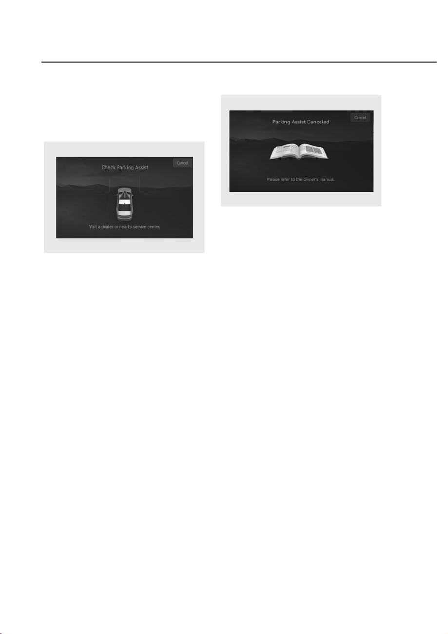
7-168
Driver Assistance System
5HPRWH6PDUW3DUNLQJ$VVLVW
0DOIXQFWLRQDQG/LPLWDWLRQV
Remote Smart Parking Assist
malfunction
ORS071281L
ORS071281L
Remote Smart Parking Assist check
When Remote Smart Parking Assist is
not working properly, the ‘Check Parking
Assist’ warning message will appear
on the infotainment system screen.
If the message appears, stop using
Remote Smart Parking Assist, and have
the vehicle inspected by an authorized
retailer of Genesis Branded products.
OJWEV071287L
OJWEV071287L
Remote Smart Parking Assist canceled
When Remote Parking Assist is
operating, the function can be canceled,
and the ‘Parking Assist Canceled’
warning message may appear regardless
of the parking order. Other messages
may appear depending on the situations.
Follow the instructions provided on
the infotainment system screen while
parking your vehicle with Remote
Parking Assist. Always look around and
pay attention when using Remote Smart
Parking Assist.
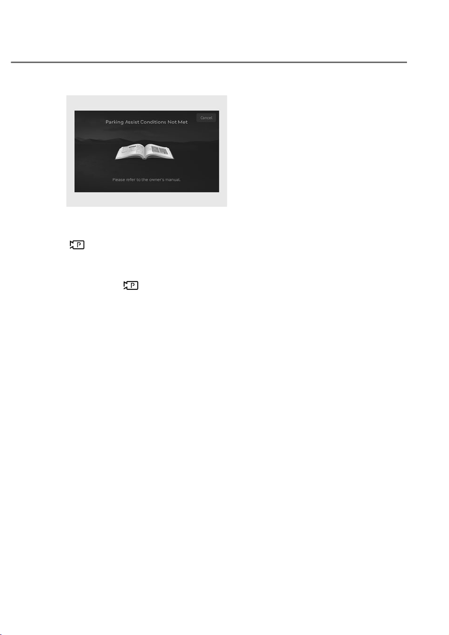
7-169
07
OJWEV071288L
OJWEV071288L
Remote Smart Parking Assist standby
‘Parking Assist Conditions Not Met’
message appears when Parking/View
(
) button has been pressed and held
while Remote Smart Parking Assist is in
standby.
After a while, press and hold the
Parking/View (
) button again to see if
Remote Smart Parking Assist works.
The message appears even when the
smart key's battery is low. Check the
smart key battery level.
Limitations of Remote Smart Parking
Assist
In the following circumstances, Remote
Smart Parking Assist performance to
park or exit the vehicle may be limited,
there may be a risk of collision, or
Remote Smart Parking Assist may turn
off. Park or exit the vehicle manually if
necessary.
• An object is attached to the steering
wheel
• The vehicle is installed with a snow
chain, spare tire or different size
wheel
• Tire pressure is lower or higher than
the standard tire pressure
• Your vehicle is loaded with cargo
longer or wider than your vehicle or a
trailer is connected to your vehicle
• There is a problem with the wheel
alignment
• Your vehicle is leaned severely to one
side
• Your vehicle is equipped with a trailer
hitch
• The license plate is installed
differently from the original location
• There is a person, animal or object
above or below the ultrasonic sensor
when Remote Smart Parking Assist is
activated
• The parking space is narrow or curve
• There is an obstacle such as a person,
animal or object (trash can, bicycle,
motorcycle, shopping cart, narrow
pillar, etc.) near the parking space
• There is a circular pillar or narrow
pillar, or a pillar surrounded by objects
such as fire extinguisher, etc., near the
parking space
• The road surface is bumpy (curbstone,
speed bump, etc.)
• The road is slippery
• The parking space is near a vehicle
with higher ground clearance or big,
such as a truck, etc.
• The parking space is Inclined

7-170
Driver Assistance System
• The road surface of parking space
with lines is wet due to snow, puddles,
or there is a road marker inside the
parking space
• The road surface of the parking space
with lines is bumpy due to road cracks
• The parking line is too thin or thick
• The parking line is partially erased or
blurred
• The parking line is obscured by
people, animals, or objects such as
snow, boxes, etc.
• There is heavy wind
• Operating Remote Smart Parking
Assist on uneven roads, gravel roads,
bushes, etc.
• The performance of the ultrasonic
sensor is affected by extremely hot or
cold weather
• The ultrasonic sensor is covered with
snow or water
• An object that generates ultrasonic
waves is nearby
• A wireless device with a transmission
function operates near the ultrasonic
sensors
• Your vehicle is affected by another
vehicle’s Parking Distance Warning
• The sensor is mounted or positioned
incorrectly by an impact to the
bumper
• The cameras is improperly mounted
or out of position due to side view
mirror damage
• The ultrasonic sensor cannot detect
the following objects when:
- Sharp or slim objects, such as ropes,
chains or small poles
- Objects smaller than 40 in. (100 cm)
in length and narrower than 6 in. (14
cm) in diameter
- Objects which tend to absorb
sensor frequency, such as clothes,
spongy material or snow
- A narrow object such as a corner of
a square pillar
- Person, animal or object near the
ultrasonic sensor
• The cameras may not properly
recognize or may not recognize the
parking line and objects when:
- There are small objects (curb, etc.),
sharp objects, or thin objects (rope,
etc.) around
- People, animals or objects are too
close or too far from the vehicle
- Objects are on a higher position,
such as pickup trucks
- The camera is obscured by dirt or
moisture
- The camera is exposed to bright
light
- The surrounding is too dark
- The light is reflected from the
surface
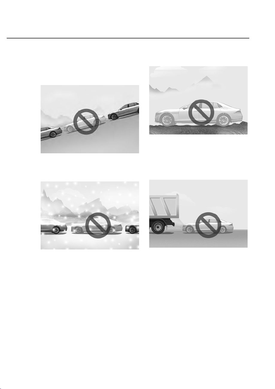
7-171
07
Remote Smart Parking Assist may not
operate properly under the following
circumstances:
• Parking on inclines
ORS072020
ORS072020
Park manually when parking on
inclines.
• Parking in snow
ORS072033
ORS072033
Snow may interfere with sensor
operation, or Remote Smart Parking
Assist may cancel if the road is
slippery while parking.
• Parking on uneven road
ORS072021
ORS072021
Remote Smart Parking Assist may
cancel when the vehicle slips, or
the vehicle cannot move due to
road conditions such as pebbles or
fragmented stones.
• Parking behind a truck
ORS072022
ORS072022
Do not use Remote Smart Parking
Assist around vehicles with higher
ground clearance, such as a bus,
truck, etc. It may lead to an accident.
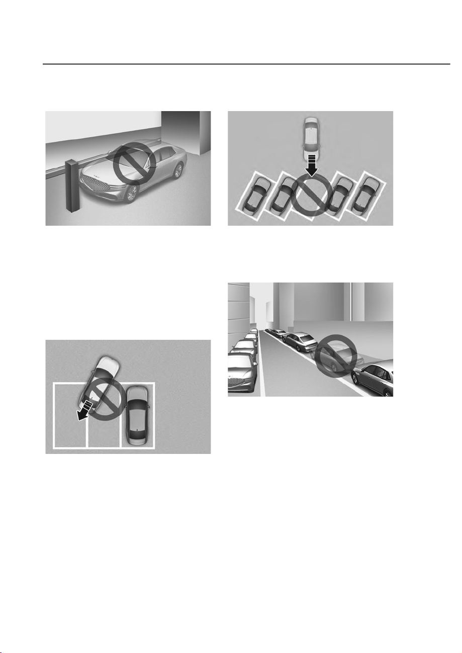
7-172
Driver Assistance System
• Parking near a pillar
ORS072023
ORS072023
Remote Smart Parking Assist
performance may reduce or collision
with an obstacle may occur when
there is a narrow object, circular pillar,
square pillar, or a pillar surrounded
by objects such as a fire extinguisher,
etc., near the parking space. The
driver should park the vehicle
properly.
• Parking next to a misaligned vehicle
ORS072032
ORS072032
If Remote Smart Parking Assist is used
in a parking space where the vehicle
next to you is parked crooked, your
vehicle can avoid contacting parked
vehicles but may not park side by side.
• Parking diagonal
ORS072034
ORS072034
Remote Operation may not operate
properly in a diagonal parking space.
• Leaving a parking space near a wall or
parking in a narrow space
ORS072137
ORS072137
- Remote Smart Parking Assist may
not operate properly when leaving
a parking space that is narrow
and near a wall. Always check for
pedestrians, animals, objects while
leaving.
- For your safety, Remote Smart
Parking Assist does not search for
parking spaces at areas with narrow
parking spaces that are narrower
than the minimum space required
for parking.
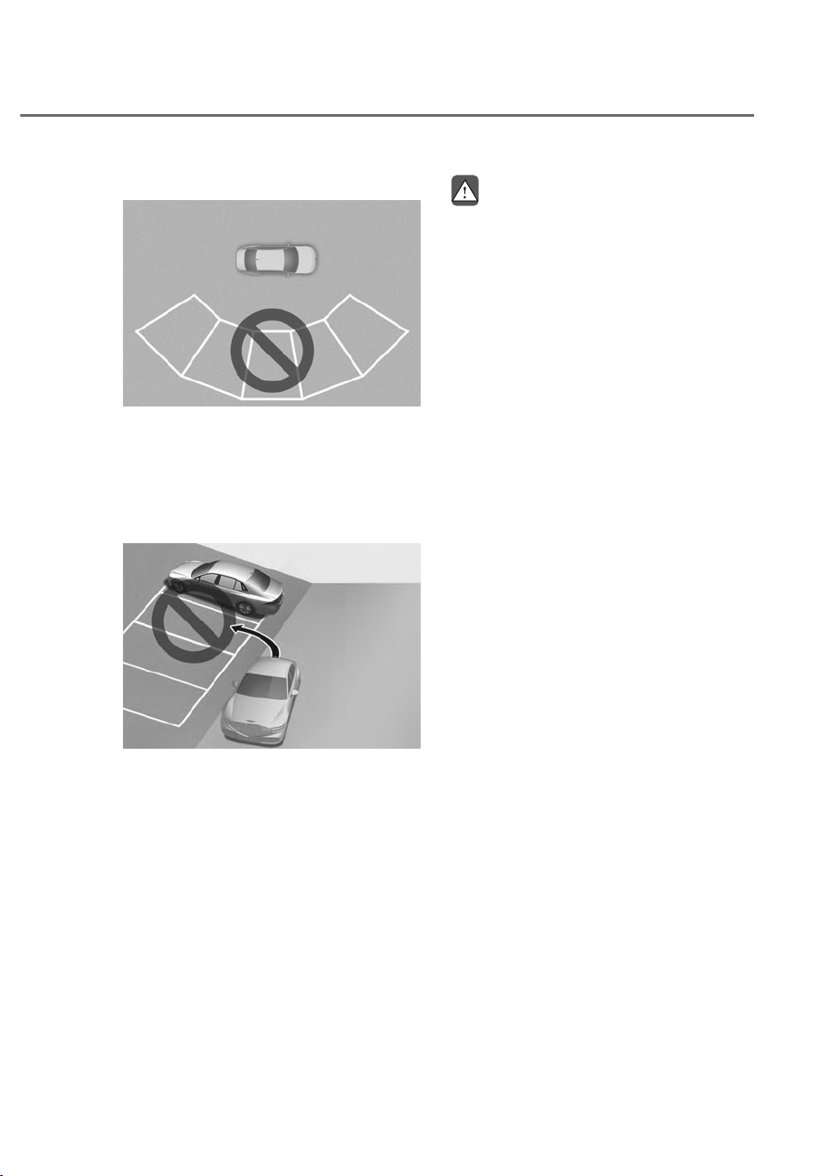
7-173
07
• Abnormal parking space
ORS072077
ORS072077
Remote Smart Parking Assist does not
work properly when the parking lines
are not parallel. Do not park even if
the parking space is recognized by the
sensor.
• Inclined parking space
ORS072078
ORS072078
Remote Smart Parking Assist does not
work properly on a inclined or curved
road surface. Do not park although
the parking space is recognized by the
sensor.
WARNING
Take the following precautions when
XVLQJ5HPRWH6PDUW3DUNLQJ$VVLVW
• 7KHGULYHULVUHVSRQVLEOHIRUVDIH
SDUNLQJDQGH[LWZKHQXVLQJ5HPRWH
6PDUW3DUNLQJ$VVLVW
• :KHQXVLQJ5HPRWH6PDUW3DUNLQJ
$VVLVWVWD\RXWRIWKHYHKLFOHȂVSDWK
IRU\RXUVDIHW\
• $OZD\VFKHFNVXUURXQGLQJVZKHQ
XVLQJ5HPRWH6PDUW3DUNLQJ$VVLVW
<RXPD\FROOLGHZLWKSHGHVWULDQV
DQLPDOVRUREMHFWVLIWKH\DUHQHDU
WKHVHQVRURUDUHLQWKHVHQVRUȂVEOLQG
VSRWDUHD
• $FROOLVLRQPD\RFFXULIDSHGHVWULDQ
DQLPDORUREMHFWVXGGHQO\DSSHDUV
ZKLOH5HPRWH6PDUW3DUNLQJ$VVLVWLV
RSHUDWLQJ
• 'RQRWXVH5HPRWH6PDUW3DUNLQJ
Assist when under the influence of
DOFRKRO
• Do not let children or other people to
XVHWKHVPDUWNH\
• ,I5HPRWH6PDUW3DUNLQJ$VVLVWLV
XVHGFRQWLQXRXVO\IRUDORQJSHULRG
LWPD\DGYHUVHO\DIIHFW5HPRWH
6PDUW3DUNLQJ$VVLVWSHUIRUPDQFH

7-174
Driver Assistance System
• 5HPRWH6PDUW3DUNLQJ$VVLVWPD\
QRWRSHUDWHSURSHUO\LIWKHYHKLFOH
QHHGVZKHHODOLJQPHQWDGMXVWPHQW
VXFKDVZKHQWKHYHKLFOHWLOWVWRRQH
VLGH+DYHWKHYHKLFOHLQVSHFWHGE\
DQDXWKRUL]HGUHWDLOHURI*HQHVLV
%UDQGHG3URGXFWV
• 1RLVHPD\EHKHDUGZKHQEUDNLQJ
RFFXUVE\5HPRWH6PDUW3DUNLQJ
$VVLVWRUZKHQWKHEUDNHSHGDOLV
GHSUHVVHGE\WKHGULYHU
• 5HPRWH6PDUW3DUNLQJ$VVLVWPD\
VXGGHQO\DSSO\WKHEUDNHWRDYRLG
FROOLVLRQ
• 8VH5HPRWH6PDUW3DUNLQJ$VVLVW
RQO\LQDSDUNLQJVSDFHWKDWLVODUJH
HQRXJKIRUWKHYHKLFOHWRPRYH
VDIHO\
NOTICE
• ,IWKHȺUGVWDJHZDUQLQJFRQWLQXRXV
EHHSRIWKH)RUZDUG5HYHUVH
3DUNLQJ'LVWDQFH:DUQLQJVRXQGV
ZKLOH5HPRWH6PDUW3DUNLQJ
$VVLVWLVRSHUDWLQJLWPHDQVWKH
REVWDFOHGHWHFWHGLVFORVHWR\RXU
YHKLFOH$WWKLVWLPH5HPRWH6PDUW
3DUNLQJ$VVLVWZLOOWHPSRUDULO\VWRS
RSHUDWLQJ0DNHVXUHWKHUHDUHQR
SHGHVWULDQVDQLPDOVRUREMHFWV
DURXQG\RXUYHKLFOH
• 'HSHQGLQJRQEUDNHRSHUDWLRQWKH
VWRSOLJKWVPD\FRPHRQZKLOHWKH
YHKLFOHLVPRYLQJ
• ,IWKHYHKLFOHLVUHPRWHO\VWDUWHGWKDW
KDVEHHQSDUNHGLQFROGZHDWKHUIRU
DORQJWLPHWKHRSHUDWLRQRI5HPRWH
6PDUW3DUNLQJIXQFWLRQPD\EH
GHOD\HGRUFDQFHOHGGHSHQGLQJRQ
WKHYHKLFOHFRQGLWLRQ
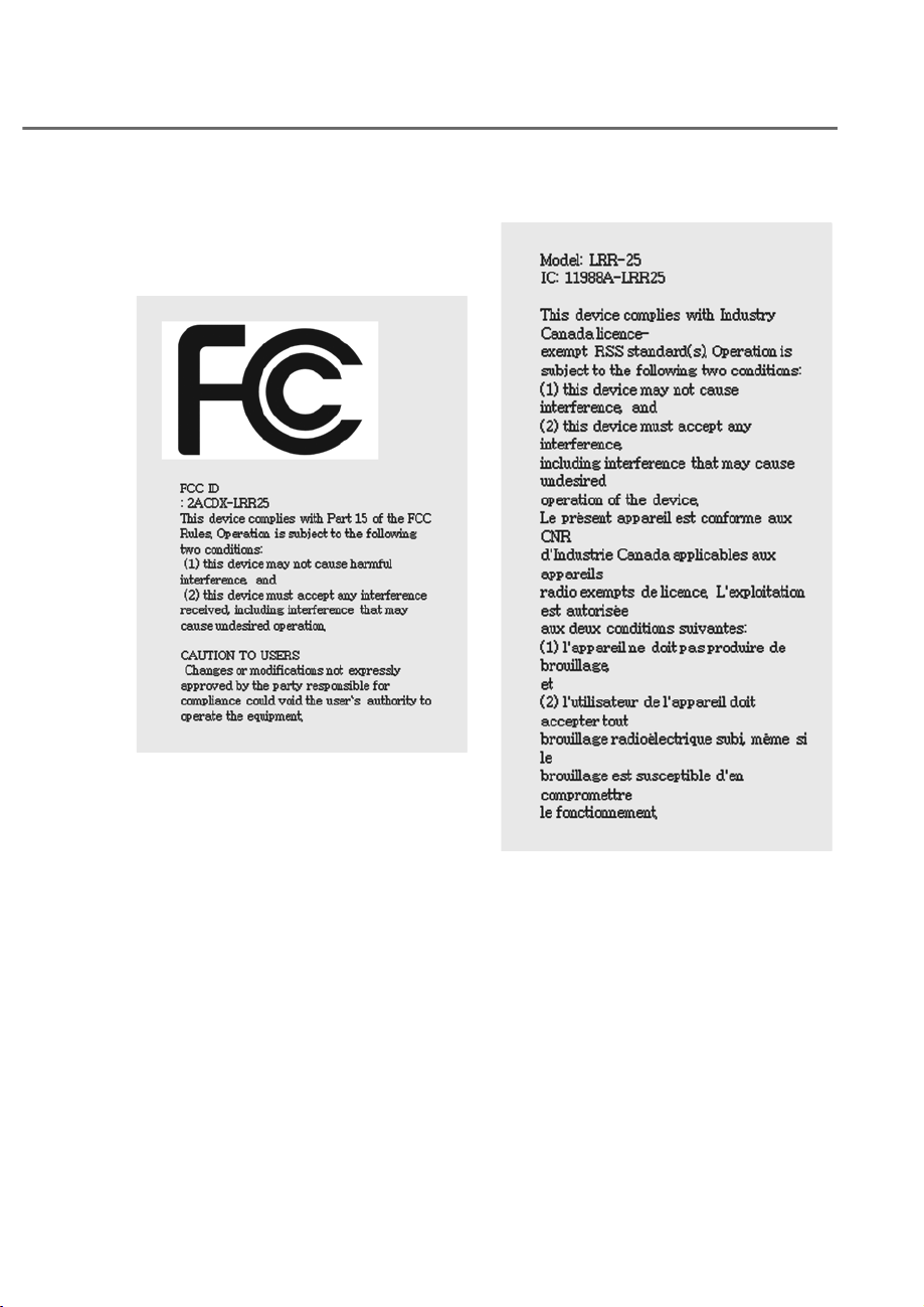
7-175
07
'(&/$5$7,212)&21)250,7<ʚ,)(48,33('ʛ
Front Radar
The radio frequency components
complies:
- For USA
OANATEL284
OANATEL284
- For Canada
OANATEL286
OANATEL286
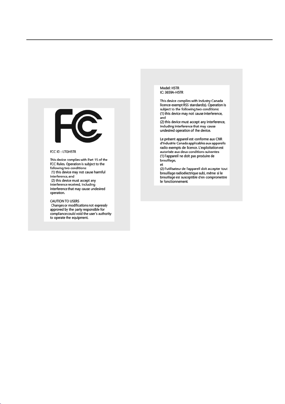
7-176
Driver Assistance System
Front Corner Radar/Rear Corner
Radar
The radio frequency components
complies:
- For USA
OANATEL352
OANATEL352
- For Canada
OANATEL353
OANATEL353

8
Hazard Warning Flasher ................................................................................... 8-2
In Case of an Emergency while Driving........................................................... 8-2
If the Engine Stalls While Driving ................................................................................8-2
If the Engine Stalls at a Crossroad or Crossing
..........................................................8-2
If You Have a Flat Tire While Driving
...........................................................................8-3
If the Engine will not Start ................................................................................ 8-3
Jump Starting
................................................................................................... 8-4
Jump Starting Procedure ............................................................................................8-5
If the Engine Overheats .................................................................................... 8-7
Tire Pressure Monitoring System (TPMS)
........................................................ 8-8
Check Tire Pressure ......................................................................................................8-8
Tire Pressure Monitoring System
................................................................................8-9
Low Tire Pressure Warning Light
.............................................................................. 8-10
Low Tire Pressure Position and Tire Pressure Telltale
............................................. 8-10
TPMS (Tire Pressure Monitoring System) Malfunction Indicator
........................... 8-11
Changing a Tire with TPMS
...................................................................................... 8-11
If you have a Flat Tire (with Spare Tire) .........................................................8-13
Jack and Tools ........................................................................................................... 8-13
Changing Tires
........................................................................................................... 8-14
Jack Label
.................................................................................................................. 8-19
If you have a Flat Tire (with Tire Mobility Kit) ................................................8-20
Introduction ............................................................................................................... 8-20
Notes On the Safe Use of the Tire Mobility Kit
........................................................ 8-21
Components of the Tire Mobility Kit
........................................................................ 8-22
Using the Tire Mobility Kit
........................................................................................ 8-23
How to Adjust Tire Pressure
..................................................................................... 8-27
Towing .............................................................................................................8-28
Towing Service .......................................................................................................... 8-28
Removable Towing Hook
.......................................................................................... 8-29
Emergency Towing
.................................................................................................... 8-30
8. Emergency Situations

8-2
Emergency Situations
ORS081001
ORS081001
The hazard warning flasher serves as
a warning to other drivers to exercise
extreme caution when approaching,
overtaking, or passing your vehicle.
It should be used whenever emergency
repairs are being made or when the
vehicle is stopped near the edge of a
roadway.
To turn the hazard warning flasher on
or off, press the hazard warning flasher
button with the Engine Start/Stop button
in any position. The hazard warning
flasher button is located in the center
fascia panel. All turn signal lights will
flash simultaneously.
• The hazard warning flasher operates
regardless of whether your vehicle is
running or not.
• The turn signals do not work when the
hazard flasher is on.
If the Engine Stalls While Driving
• Reduce your speed gradually, keeping
a straight line. Move cautiously off the
road to a safe place.
• Turn on your hazard warning flasher.
• Try to start the engine again. If your
vehicle will not start, we recommend
that you contact an authorized retailer
of Genesis Branded products or seek
other qualified assistance.
If the Engine Stalls at a Crossroad
or Crossing
If the engine stalls at a crossroads or
crossing, if safe to do so, shift the gear to
N (Neutral) and then push the vehicle to
a safe location.
HAZARD WARNING FLASHER IN CASE OF AN EMERGENCY
WHILE DRIVING

8-3
08
If You Have a Flat Tire While
Driving
If a tire goes flat while you are driving:
• Take your foot off the accelerator
pedal and let the vehicle slow down
while driving straight ahead. Do not
apply the brakes immediately or
attempt to pull off the road as this
may cause loss of vehicle control
resulting in an accident. When the
vehicle has slowed to such a speed
that it is safe to do so, brake carefully
and pull off the road. Drive off the
road as far as possible and park on
firm, level ground. If you are on a
divided highway, do not park in the
median area between the two traffic
lanes.
• When the vehicle is stopped, press the
hazard warning flasher button, shift
the gear to P (Park), apply the parking
brake, and press the Engine Start/Stop
button to the OFF position.
• Have all passengers get out of the
vehicle. Be sure they all get out on the
side of the vehicle that is away from
traffic.
• When changing a flat tire, follow the
instructions provided later in this
chapter.
IF THE ENGINE WILL NOT
START
• Be sure to shift the gear to N (Neutral)
or P (Park). The engine starts only
when the gear is in N (Neutral) or P
(Park).
• Turn on the interior light. If the light
dims or goes out when you operate
the starter, the battery is drained.
See instructions for “Jump Starting”
provided in this chapter.
• Check the fuel level and add fuel if
necessary.
If the vehicle still does not start, call an
authorized retailer of Genesis Branded
products for assistance.
NOTICE
Push or pull starting the vehicle may
cause the catalytic converter to
overload which can lead to damage to
the emission control system.
8-4
Emergency Situations
Jump starting can be dangerous if done
incorrectly. Follow the jump starting
procedure in this section to avoid serious
injury or damage to your vehicle. If in
doubt about how to properly jump start
your vehicle, we strongly recommend
that you have a service technician or
towing service do it for you.
WARNING
To prevent SERIOUS INJURY or DEATH
to you or bystanders, always follow
these precautions when working near
or handling the battery:
Always read and follow
instructions carefully when
handling a battery.
Wear eye protection designed
to protect the eyes from acid
splashes.
Keep all flames, sparks, or
smoking materials away from
the battery.
Hydrogen is always present
in battery cells, is highly
combustible, and may explode
if ignited.
Keep batteries out of reach of
children.
Batteries contain sulfuric acid
which is highly corrosive. Do
not allow acid to contact your
eyes, skin or clothing.
If acid gets into your eyes, flush your
eyes with clean water for at least 15
minutes and get immediate medical
attention. If acid gets on your skin,
thoroughly wash the area. If you feel
pain or a burning sensation, get medical
attention immediately.
• When lifting a plastic-cased battery,
excessive pressure on the case may
cause battery acid to leak. Lift with a
battery carrier or with your hands on
opposite corners.
• Do not attempt to jump start your
vehicle if your battery is frozen.
• NEVER attempt to recharge the
battery when the vehicle’s battery
cables are connected to the battery.
• The electrical ignition system works
with high voltage.
NEVER touch these components
with the engine running or when the
Engine Start/Stop button is in the ON
position.
JUMP STARTING
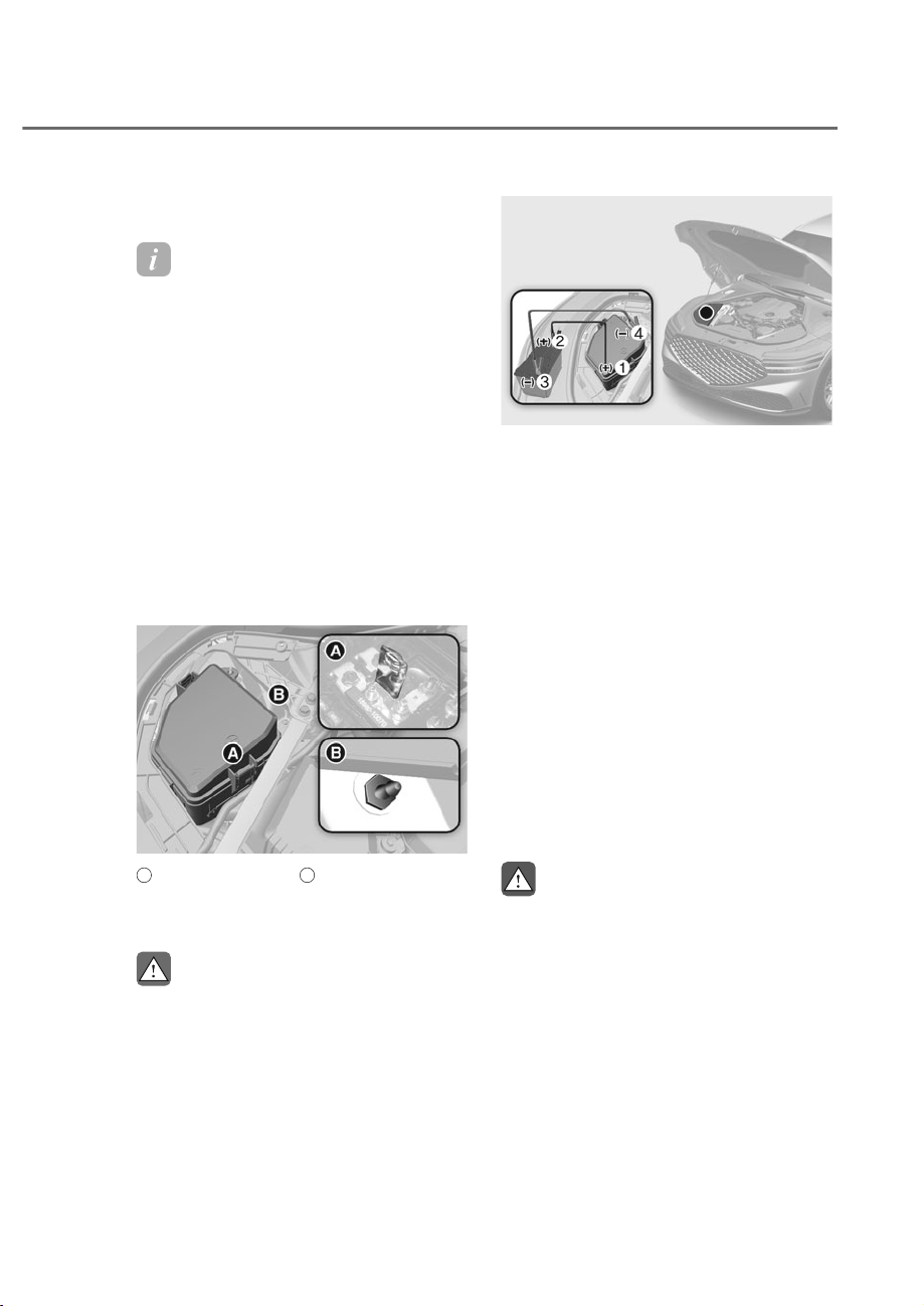
8-5
08
Jump Starting Procedure
Information
Your vehicle has a battery in the luggage
compartment, but when you ump start
your vehicle, use the umper terminal in
the engine compartment.
1. Position the vehicles close enough
that the jumper cables will reach, but
do not allow the vehicles to touch.
2. Avoid fans or any moving parts in the
engine compartment at all times, even
when the vehicles are turned off.
3. Turn off all electrical devices such as
radios, lights, air conditioning, etc.
Put the vehicles in P (Park) and set the
parking brake. Turn both vehicles OFF.
4. Open the engine hood.
ORS081020
ORS081020
A
: Negative (-) Terminal,
B
: Positive (+) Terminal
5. Remove the engine compartment fuse
box cover.
CAUTION
Before jump starting, make sure to
correctly identify the positive (+) and
negative (-) terminals to avoid reverse
polarity connections.
ORS082003N
ORS082003N
6. Connect the jumper cables in
the exact sequence shown in the
illustration. First connect one jumper
cable to the red, positive (+) jumper
terminal of your vehicle M.
7. Connect the other end of the jumper
cable to the red, positive (+) battery/
jumper terminal of the assisting
vehicle N.
8. Connect the second jumper cable to
the black, negative (-) battery/jumper
terminal of the assisting vehicle O.
9.
Connect the other end of the second
jumper cable to the black, negative (-)
chassis ground of your vehicle P.
Do not allow the jumper cables to
contact anything except the correct
battery or jumper terminals or the
correct ground. Do not lean over the
battery when making connections.
WARNING
Do not connect the jumper cable to
the negative (-) jumper terminal of the
discharged battery. A spark could cause
the battery to explode and lead to a
personal injury or vehicle damage.

8-6
Emergency Situations
10.
Start the engine of the assisting
vehicle and let it run at approximately
2,000 RPM for a few minutes. Then
start your vehicle.
11.
Keep your vehicle operating for at
least 30 minutes at idle or driving to
assure your battery receives enough
charge to be able to start on its
own after the vehicle is shut off. A
completely discharged battery may
require as long as 60 minutes runtime
to fully recharge it. If the vehicle is run
for less, the vehicle may not restart.
If your vehicle will not start after a few
attempts, it probably requires service.
In this event please seek qualified
assistance. If the cause of your battery
discharging is not apparent, have your
vehicle checked by an authorized retailer
of Genesis Branded products.
Disconnect the jumper cables in the
exact reverse order you connected them:
1. Disconnect the jumper cable from the
black, negative (-) chassis ground of
your vehicle P.
2. Disconnect the other end of the
jumper cable from the black, negative
(-) battery/chassis ground of the
assisting vehicle O.
3. Disconnect the second jumper cable
from the red, positive (+) battery/
jumper terminal of the assisting
vehicle N.
4. Disconnect the other end of the
jumper cable from the red, positive (+)
jumper terminal of your vehicle M.
Information
An inappropriately disposed
battery can be harmful to
the environment and human
health. Dispose of the battery
according to your local law(s) or
regulations.
NOTICE
To prevent damage to your vehicle:
• Only use a 12-volt power supply
(battery or jumper system) to jump
start your vehicle.
• Do not attempt to jump start your
vehicle by push-starting.
WARNING
While jump starting your vehicle, avoid
the positive (+) and negative (-) cables
to come in contact. A spark could cause
personal injury.
WARNING
48 V lithium battery (if equipped)
Do not jump start another vehicle.
The 48 V lithium polymer type battery
installed in your vehicle will be
damaged.

8-7
08
If your temperature gauge indicates
overheating, you experience a loss of
power, or hear loud pinging or knocking,
the engine may be overheating. If this
happens, you should:
1. Pull off the road and stop as soon as it
is safe to do so.
2. Shift the gear to P (Park) and set the
parking brake. If the air conditioning is
ON, turn it OFF.
3. If engine coolant is running out under
the vehicle or steam is coming out
from the hood, stop the engine. Do
not open the hood until the coolant
has stopped running or the steaming
has stopped. If there is no visible
loss of engine coolant and no steam,
leave the engine running and check
to be sure the engine cooling fan is
operating. If the fan is not running,
turn the engine off.
WARNING
While the engine is running,
keep hands, clothing and tools
away from the moving parts
such as the cooling fan and
drive belt to prevent serious
injury.
4. Check for coolant leaking from the
radiator, hoses or under the vehicle. (If
the air conditioning had been in use, it
is normal for cold water to be draining
from it when you stop.)
5. If engine coolant is leaking out, stop
the engine immediately and call the
nearest authorized retailer of Genesis
Branded products for assistance.
WARNING
Never remove the engine
coolant cap and/or liquid-
cooled intercooler coolant
cap or the drain plug while the
engine and radiator are hot.
Hot coolant and steam may blow out
under pressure, causing serious injury.
Turn the engine off and wait until the
engine cools down. Use extreme care
when removing the radiant cap or
coolant cap. Wrap a thick towel around
it, and turn it counterclockwise slowly
to the first stop. Step back while the
pressure is released from the cooling
system. When you are sure all the
pressure has been released, press down
on the cap, using a thick towel, and
continue turning counterclockwise to
remove it.
6. If you cannot find the cause of the
overheating, wait until the engine
temperature has returned to normal.
Then, if coolant has been lost,
carefully add coolant to the reservoir
to bring the fluid level in the reservoir
up to the halfway mark.
7. Proceed with caution, keeping alert
for further signs of overheating. If
overheating happens again, call an
authorized retailer of Genesis Branded
products for assistance.
CAUTION
• Serious loss of coolant indicates a
leak in the cooling system and should
be checked as soon as possible by
an authorized retailer of Genesis
Branded products.
• When the engine overheats from
low engine coolant, suddenly
adding engine coolant may cause
cracks in the engine. To prevent
damage, add engine coolant slowly
in small quantities. It may require
several refilling cycles to properly
fill the engine cooling system. If
necessary, an authorized retailer of
Genesis Branded products should be
consulted to perform this task.
IF THE ENGINE OVERHEATS
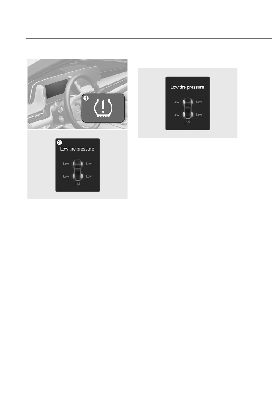
8-8
Emergency Situations
ORS081004
ORS081004
ORS081027L
ORS081027L
M Low Tire Pressure Telltale/TPMS
Malfunction Indicator
N
Low Tire Pressure Position Telltale and
Tire Pressure Telltale (Shown on the
LCD display)
Check Tire Pressure
ORS081028L
ORS081028L
• You can check the tire pressure in the
Normal view on the cluster.
Refer to the “View Modes” section in
chapter 4.
• Tire pressure is displayed after a few
minutes of driving after initial vehicle
start up.
• If tire pressure is not displayed when
the vehicle is stopped, ‘Drive to
display’ message will appear. After
driving, check the tire pressure.
• The displayed tire pressure values may
differ from those measured with a tire
pressure gauge.
• You can change the tire pressure
unit from the Settings menu in the
infotainment system screen. Select:
- 6HWXSɌ*HQHUDOɌ8QLWVɌ7LUH$LU
3UHVVXUHɌSVLN3DEDU
For detailed information, refer to the
separately supplied manual.
7,5(35(6685(021,725,1*6<67(0ʚ7306ʛ

8-9
08
Tire Pressure Monitoring System
WARNING
Over-inflation or under-inflation can
reduce tire life, adversely affect vehicle
handling, and lead to sudden tire failure
that may cause loss of vehicle control
resulting in an accident.
Each tire, including the spare (if
provided), should be checked monthly
when cold and inflated to the inflation
pressure recommended by the vehicle
manufacturer on the vehicle placard
or tire inflation pressure label. (If your
vehicle has tires of a different size than
the size indicated on the vehicle placard
or tire inflation pressure label, you should
determine the proper tire inflation
pressure for those tires.)
As an added safety feature, your
vehicle has been equipped with a tire
pressure monitoring system (TPMS)
that illuminates a low tire pressure
telltale when one or more of your tires is
significantly under-inflated. Accordingly,
when the low tire pressure telltale
illuminates, you should stop and check
your tires as soon as possible, and inflate
them to the proper pressure. Driving on
a significantly under-inflated tire causes
the tire to overheat and can lead to tire
failure.
Under-inflation also reduces fuel
efficiency and tire tread life, and may
affect the vehicle’s handling and
stopping ability.
Please note that the TPMS is not a
substitute for proper tire maintenance,
and it is the driver’s responsibility to
maintain correct tire pressure, even if
under-inflation has not reached the level
to trigger illumination of the TPMS low
tire pressure telltale.
Your vehicle has also been equipped with
a TPMS malfunction indicator to indicate
when the system is not operating
properly. The TPMS malfunction
indicator is combined with the low
tire pressure telltale. When the system
detects a malfunction, the telltale will
flash for approximately one minute and
then remain continuously illuminated.
This sequence will continue upon
subsequent vehicle start-ups as long as
the malfunction exists.
When the malfunction indicator is
illuminated, the system may not be able
to detect or signal low tire pressure as
intended. TPMS malfunctions may occur
for a variety of reasons, including the
installation of replacement or alternate
tires or wheels on the vehicle that
prevent the TPMS from functioning
properly.
Always check the TPMS malfunction
telltale after replacing one or more tires
or wheels on your vehicle to ensure that
the replacement or alternate tires and
wheels allow the TPMS to continue to
function properly.
NOTICE
If any of the below happens, have
the system checked by an authorized
retailer of Genesis Branded products.
1. The Low Tire Pressure Telltale/ TPMS
Malfunction Indicator does not
illuminate for 3 seconds when the
Engine Start/Stop button is pressed
to the ON position or when the
engine is running.
2. The TPMS Malfunction Indicator
remains illuminated after blinking for
approximately 1 minute.
3. The Low Tire Pressure Position
Telltale remains illuminated.
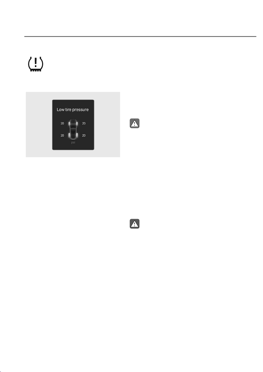
8-10
Emergency Situations
Low Tire Pressure
Warning Light
Low Tire Pressure Position and
Tire Pressure Telltale
ORS081029L
ORS081029L
When the tire pressure monitoring
system warning indicators are
illuminated and a warning message
displayed on the cluster LCD display,
one or more of your tires is significantly
under-inflated. The Low Tire Pressure
Position Telltale will indicate which
tire is significantly underinflated by
illuminating the corresponding position
light.
If either telltale illuminates, immediately
reduce your speed, avoid hard cornering
and anticipate increased stopping
distances. You should stop and check
your tires as soon as possible. Inflate the
tires to the proper pressure as indicated
on the vehicle’s placard or tire inflation
pressure label located on the driver’s
side center pillar outer panel.
If you cannot reach a service station or
if the tire cannot hold the newly added
air, replace the low pressure tire with the
spare tire.
The Low Tire Pressure LCD position
indicator will remain on and the TPMS
Malfunction Indicator may blink for one
minute and then remain illuminated until
you have the low pressure tire repaired
and replaced on the vehicle.
CAUTION
In winter or cold weather, the Low Tire
Pressure Telltale may be illuminated if
the tire pressure was adjusted to the
recommended tire inflation pressure
in warm weather. It does not mean
your TPMS is malfunctioning because
the decreased temperature leads to a
proportional lowering of tire pressure.
When you drive your vehicle from a
warm area to a cold area or from a cold
area to a warm area, or the outside
temperature is greatly higher or lower,
you should check the tire inflation
pressure and adjust the tires to the
recommended tire inflation pressure.
WARNING
Low pressure damage
Significantly low tire pressure makes
the vehicle unstable and can contribute
to loss of vehicle control and increased
braking distances.
Continued driving on low pressure tires
can cause the tires to overheat and fail.

8-11
08
TPMS (Tire Pressure
Monitoring System)
Malfunction Indicator
The TPMS Malfunction Indicator
will illuminate after it blinks for
approximately one minute when there
is a problem with the Tire Pressure
Monitoring System.
Have the system checked by an
authorized retailer of Genesis Branded
products as soon as possible.
NOTICE
If there is a malfunction with the TPMS,
the Low Tire Pressure Position Telltale
will not be displayed even though the
vehicle has an under-inflated tire.
NOTICE
The TPMS Malfunction Indicator may
illuminate after blinking for one minute
if the vehicle is near electric power
supply cables or radio transmitters
such as police stations, government
and public offices, broadcasting
stations, military installations, airports,
transmitting towers, etc.
Additionally, the TPMS Malfunction
Indicator may illuminate if snow chains
are used or electronic devices such as
computers, chargers, remote starters,
navigation, etc. This may interfere with
normal operation of the TPMS.
Changing a Tire with TPMS
If you have a flat tire, the Low Tire
Pressure and Position telltales will come
on. Have the flat tire repaired by an
authorized retailer of Genesis Branded
products as soon as possible or replace
the flat tire with the spare tire.
NOTICE
It is recommended that you do not use a
puncture-repairing agent not approved
by an authorized retailer of Genesis
Branded products to repair and/or
inflate a low pressure tire. Tire sealant
not approved by an authorized retailer
of Genesis Branded products may
damage the tire pressure sensor.
The spare tire does not come with a
tire pressure monitoring sensor. When
the low pressure tire or the flat tire is
replaced with the spare tire, the Low
Tire Pressure LCD position indicator will
remain on. Also, the TPMS Malfunction
Indicator will illuminate after blinking
for one minute if the vehicle is driven
at speed above 15.5 mph (25 km/h) for
approximately 20 minutes.
Once the original wheel equipped with
a tire pressure monitoring sensor is
reinflated to the recommended pressure
and reinstalled on the vehicle, the
Low Tire Pressure Telltale and TPMS
Malfunction Indicator will go off within a
few minutes of driving.

8-12
Emergency Situations
If the indicators do not extinguish after
a few minutes, have visit an authorized
retailer of Genesis Branded products.
Each wheel is equipped with a tire
pressure sensor mounted inside the tire
behind the valve stem (except for the
spare tire). You must use TPMS specific
wheels. It is recommended that you
always have your tires serviced by an
authorized retailer of Genesis Branded
products.
You may not be able to identify a tire
with low pressure by simply looking at it.
Always use a good quality tire pressure
gauge to measure. Please note that a tire
that is hot (from being driven) will have a
higher pressure measurement than a tire
that is cold.
A cold tire means the vehicle has been
sitting for 3 hours and driven for less
than 1 mile (1.6 km) in that 3 hour period.
Allow the tire to cool before measuring
the inflation pressure. Always be sure
the tire is cold before inflating to the
recommended pressure.
WARNING
• The TPMS cannot alert you to severe
and sudden tire damage caused by
external factors such as nails or road
debris.
• If you feel any vehicle instability,
immediately take your foot off
the accelerator, apply the brakes
gradually with light force, and slowly
move to a safe position off the road.
WARNING
Tampering with, modifying, or disabling
the Tire Pressure Monitoring System
(TPMS) components may interfere
with the system’s ability to warn the
driver of low tire pressure conditions
and/or TPMS malfunctions. Tampering
with, modifying, or disabling the Tire
Pressure Monitoring System (TPMS)
components may void the warranty for
that portion of the vehicle.
WARNING
This device complies with Part 15 of the
FCC rules.
Operation is subject to the following
three conditions:
1. This device may not cause harmful
interference.
2. This device must accept any
interference received, including
interference that may cause
undesired operation.
3. Changes or modifications not
expressly approved by the party
responsible for compliance could
void the user’s authority to operate
the equipment.
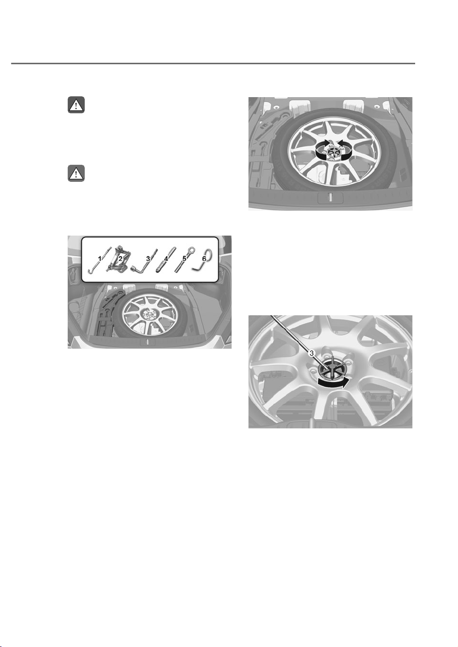
8-13
08
,)<28+$9($)/$77,5(ʚ:,7+63$5(7,5(,)(48,33('ʛ
WARNING
Changing a tire can be dangerous.
Follow the instructions in this section
when changing a tire to reduce the risk
of serious injury or death.
CAUTION
Be careful as you use the jack handle to
stay clear of the flat end. The flat end
has sharp edges that could cause cuts.
Jack and Tools
ORS081022L
ORS081022L
M Jack handle
N Jack
O Wheel lug wrench
P Centering pin
Q Towing hook
R
Tool for removing wheel cover
(ifequipped)
The jack, jack handle, and wheel lug
wrench are stored in the luggage
compartment under the luggage box
cover.
The jack is provided for emergency tire
changing only.
ORS081031L
ORS081031L
Turn the winged hold down bolt
counterclockwise to remove the spare
tire.
Store the spare tire in the same
compartment by turning the winged hold
down bolt clockwise.
To prevent the spare tire and tools from
“rattling”, store them in their proper
location.
ORS081043L
ORS081043L
If it is hard to loosen the tire hold-down
wing bolt by hand, you can loosen
it easily using the wheel lug wrench
O. Turn the tire hold-down wing bolt
counterclockwise with the wheel lug
wrench.
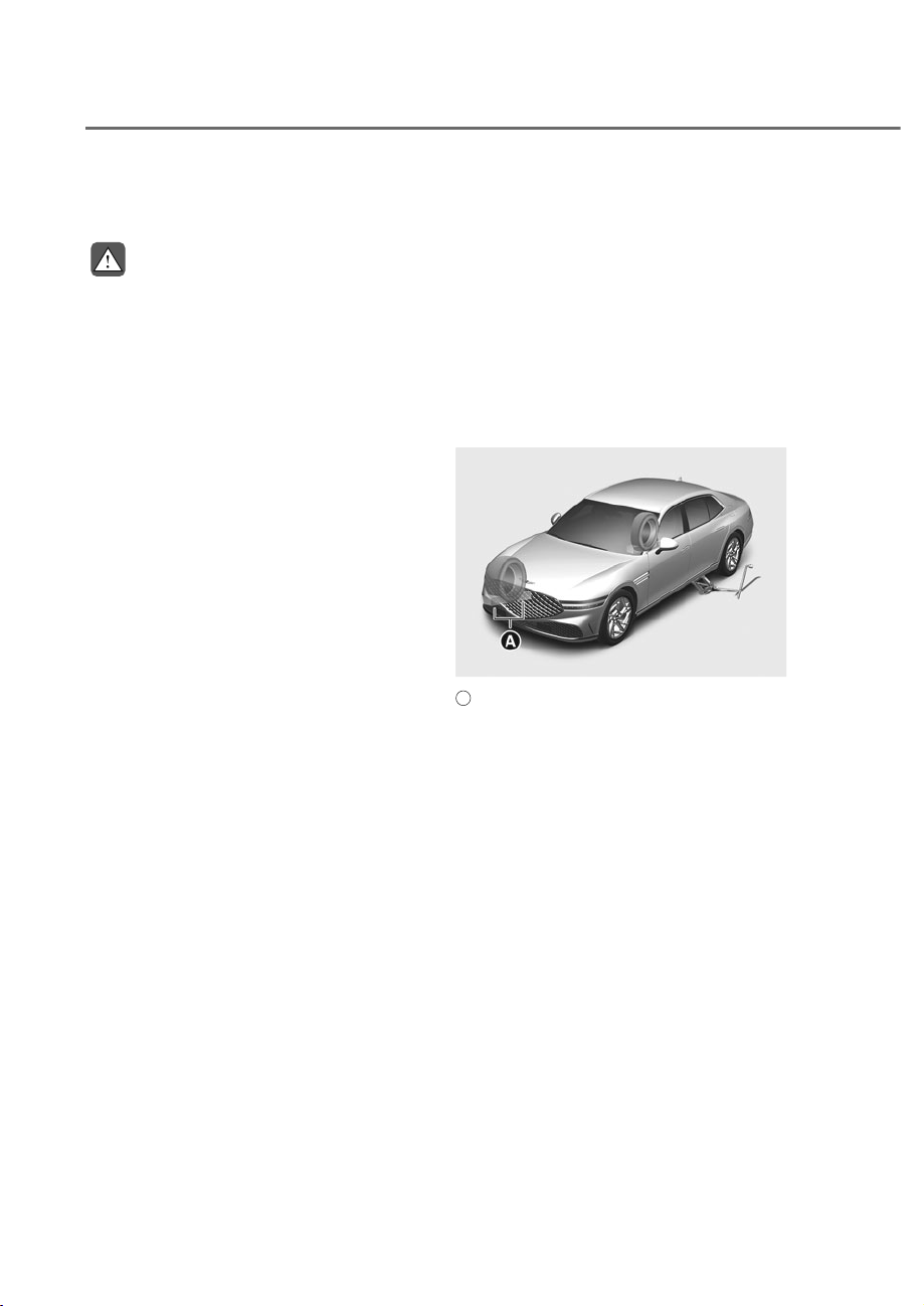
8-14
Emergency Situations
Changing Tires
WARNING
A vehicle can slip or roll off of a jack
causing serious injury or death to you or
those nearby. Take the following safety
precautions:
• Do not get under a vehicle that is
supported by a jack.
• NEVER attempt to change a tire in
the lane of traffic. ALWAYS move the
vehicle completely off the road on
level, firm ground away from traffic
before trying to change a tire. If you
cannot find a level, firm place off
the road, call a towing service for
assistance.
• Be sure to use the jack provided with
the vehicle.
• ALWAYS place the jack on the
designated jacking positions on the
vehicle and NEVER on the bumpers
or any other part of the vehicle for
jacking support.
• Do not start or run the engine while
the vehicle is on the jack.
• Do not allow anyone to remain in the
vehicle while it is on the jack.
• Keep children away from the road
and the vehicle.
Follow these steps to change your
vehicle’s tire:
1. Park on a level, firm surface.
2. Shift the gear to P (Park), apply the
parking brake, and press the Engine
Start/Stop button to the OFF position.
3. Press the hazard warning flasher
button.
4. Remove the wheel lug wrench, jack,
jack handle, and spare tire from the
vehicle.
ORS081032L
ORS081032L
A
: Block
5. Block both the front and rear of the
tire diagonally opposite of the tire you
are changing.
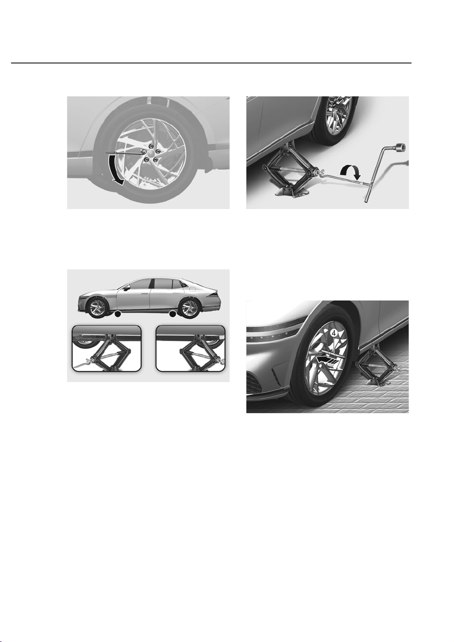
8-15
08
ORS081039L
ORS081039L
6. Loosen the wheel bolts
counterclockwise one turn each in
the order shown above, but do not
remove any wheel bolts until the tire
has been raised off of the ground.
ORS082033N
ORS082033N
7. Place the jack at the designated
jacking position under the frame
closest to the tire you are changing.
The jacking positions are plates
welded to the frame with two
notches. Never jack at any other
position or part of the vehicle. Doing
so may damage the side seal molding
or other parts of the vehicle.
ORS081034L
ORS081034L
8. Insert the jack handle into the jack
and turn it clockwise, raising the
vehicle until the tire clears the ground.
Make sure the vehicle is stable on the
jack.
9. Loosen a wheel bolt with the wheel
lug wrench and remove it with your
fingers.
ORS081035L
ORS081035L
10.
Insert the centering pin P into the
hole where the wheel bolt is removed.
Remove rest of the wheel bolts from
the wheel.
11.
Remove the wheel from the studs and
lay it flat on the ground out of the way.
Remove any dirt or debris from the
studs, mounting surfaces, and wheel.
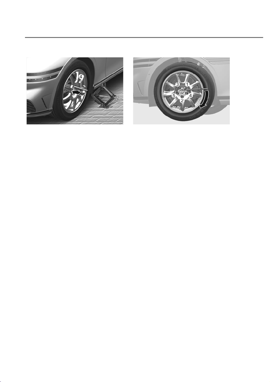
8-16
Emergency Situations
ORS081041L
ORS081041L
12.
Install the spare tire over the centering
pin P and then push in the spare tire.
13.
Tighten the wheel bolts with your
fingers onto the studs with the smaller
end of the wheel bolts closest to the
wheel.
14.
Pull out the centering pin P and
tighten the last wheel bolt.
15.
Lower the vehicle to the ground
by turning the jack handle
counterclockwise.
ORS081042L
ORS081042L
16.
Use the wheel lug wrench to tighten
the wheel bolts in the order shown.
Double-check each wheel bolts until
they are tight. After changing tires,
have an authorized retailer of Genesis
Branded products tighten the wheel
bolts to their proper torque as soon
as possible. The wheel bolt should
be tightened to 101~116 lbf·ft (14~16
kgf·m).
If you have a tire gauge, check the
tire pressure (see “Tires and Wheels”
section in chapter 2 for tire pressure
instructions.). If the pressure is lower or
higher than recommended, drive slowly
to the nearest service station and adjust
it to the recommended pressure. Always
reinstall the valve cap after checking
or adjusting tire pressure. If the cap
is not replaced, air may leak from the
tire. If you lose a valve cap, buy another
and install it as soon as possible. After
changing tires, secure the flat tire and
return the jack and tools to their proper
storage locations.

8-17
08
NOTICE
Check the tire pressure as soon as
possible after installing a spare tire.
Adjust it to the recommended pressure.
CAUTION
Your vehicle has metric threads on the
studs and wheel bolts. Make certain
during tire changing that the same bolts
that were removed are reinstalled. If
you have to replace your wheel bolts
make sure they have metric threads to
avoid damaging the studs and ensure
the wheel is properly secured to the
hub. Consult an authorized retailer
of Genesis Branded products for
assistance.
If any of the equipment such as the jack,
wheel bolts, studs, or other equipment
is damaged or in poor condition, do not
attempt to change the tire and call for
assistance.
Use of compact spare tires
Compact spare tires are designed for
emergency use only. Drive carefully on
the compact spare tire and always follow
the safety precautions.
WARNING
To prevent compact spare tire failure
and loss of control possibly resulting in
an accident:
• Use the compact spare tire only in an
emergency.
• NEVER operate your vehicle over
50 mph (80 km/h).
• Do not exceed the vehicle’s
maximum load rating or the load
carrying capacity shown on the
sidewall of the compact spare tire.
• Do not use the compact spare tire
continuously. Repair or replace the
original tire as soon as possible to
avoid failure of the compact spare
tire.

8-18
Emergency Situations
When driving with the compact spare tire
mounted to your vehicle:
• Check the tire pressure after installing
the compact spare tire. The compact
spare tire should be inflated to 60 psi
(420 kPa).
• Do not take this vehicle through
an automatic car wash while the
compact spare tire is installed.
• Do not use the compact spare tire on
any other vehicle because this tire
has been designed especially for your
vehicle.
• The compact spare tire’s tread life is
shorter than a regular tire. Inspect
your compact spare tire regularly and
replace worn compact spare tires with
the same size and design, mounted on
the same wheel.
• Do not use more than one compact
spare tire at a time.
• Do not tow a trailer while the compact
spare tire is installed.
Information
When the original tire and wheel are
repaired and reinstalled on the vehicle, the
wheel bolt torque must be set correctly.
The correct wheel bolt tightening torque is
101~116 lbf ft (14~16 kgf m).
NOTICE
To prevent damaging the compact
spare tire and your vehicle:
• Drive slowly enough for the road
conditions to avoid all hazards, such
as a potholes or debris.
• Avoid driving over obstacles. The
compact spare tire diameter is
smaller than the diameter of a
conventional tire and reduces the
ground clearance approximately
1 in. (25 mm).
• Do not use tire chains on the
compact spare tire. Because of the
smaller size, a tire chain will not fit
properly.
• Do not use the compact spare tire
on any other wheels, nor should
standard tires, snow tires, wheel
covers or trim rings be used with the
compact spare wheel.
• Do not suddenly accelerate or
decelerate 0 ~ 25 mph (0 ~ 40 km/h)
in any driving mode. It may cause
leakage of transfer oil.
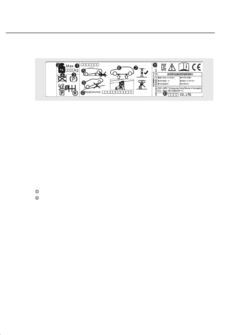
8-19
08
Jack Label
OHYK065011
OHYK065011
The actual Jack label in the vehicle may differ from the illustration.
For more detailed specifications, refer to the label attached to the jack.
M Model Name
N Maximum allowable load
O When using the jack, set your parking brake.
P When using the jack, stop the engine.
Q Do not get under a vehicle that is supported by a jack.
R The designated locations under the frame
S
When supporting the vehicle, the base plate of jack must be vertical under the lifting
point.
T
Shift into Reverse gear on vehicles with manual transmission or shift the gear to the
P position on vehicles with automatic transmission.
U The jack should be used on firm level ground.
V Jack manufacture
Production date
Representative company and address\
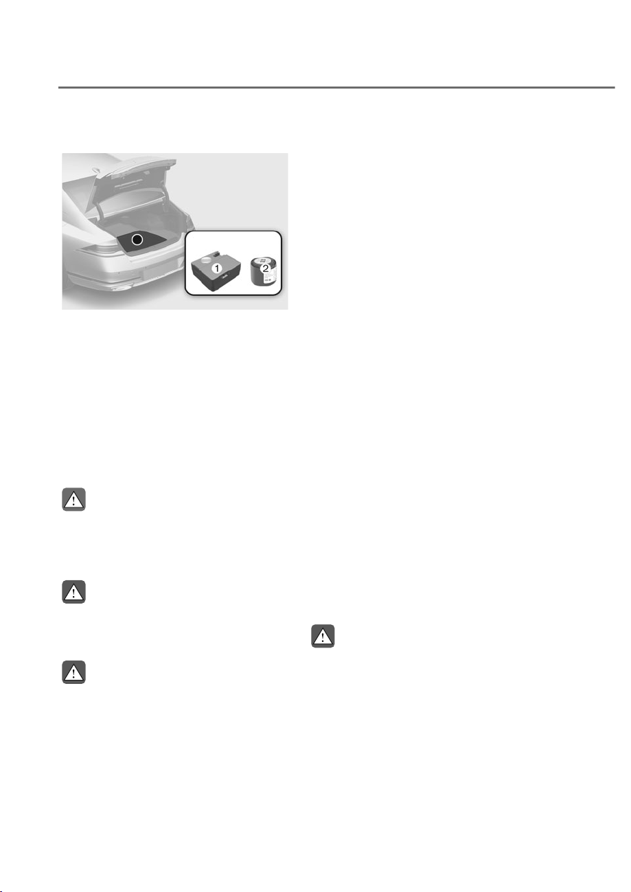
8-20
Emergency Situations
ORS081006
ORS081006
For safe operation, carefully read and
follow the instructions in this manual
before use.
M Compressor
N Sealant bottle
The Tire Mobility Kit is a temporary fix to
the tire and the tire should be inspected
by an authorized retailer of Genesis
Branded products or the equivalent
approved for your vehicle as soon as
possible.
CAUTION
When two or more tires are flat, do not
use the tire mobility kit because the
sealant provided with the Tire Mobility
Kit must be used for only one flat tire.
WARNING
Do not use the Tire Mobility Kit to repair
punctures in the tire walls. This can
result in an accident due to tire failure.
WARNING
Have your tire repaired as soon as
possible. The tire may lose air pressure
at any time after inflating with the Tire
Mobility Kit.
Introduction
With the Tire Mobility Kit you stay mobile
even after experiencing a tire puncture.
The compressor and sealing compound
system effectively and comfortably seals
most punctures in a passenger vehicle
tire caused by nails or similar objects and
reinflates the tire.
After you ensure that the tire is properly
sealed you can drive cautiously on the
tire (distance up to 120 miles (200 km))
at a max. speed of 50 mph (80 km/h) in
order to reach a service station or tire
dealer for the tire replacement.
It is possible that some tires, especially
with larger punctures or damage to the
sidewall, cannot be sealed completely.
Air pressure loss in the tire may adversely
affect tire performance.
For this reason, you should avoid abrupt
steering or other driving maneuvers,
especially if the vehicle is heavily loaded
or if a trailer is in use.
The Tire Mobility Kit is not designed
or intended as a permanent tire repair
method and is to be used for one tire
only.
This instruction shows you step by step
how to temporarily seal the puncture
simply and reliably.
Read the section “Notes on the safe use
of the Tire Mobility Kit”.
WARNING
Do not use the TMK if a tire is severely
damaged by driving run flat or with
insufficient air pressure.
Only punctured areas located within the
tread region of the tire can be sealed
using the TMK.
,)<28+$9($)/$77,5(ʚ:,7+7,5(02%,/,7<.,7,)
(48,33('ʛ

8-21
08
Notes On the Safe Use of the Tire
Mobility Kit
• Park your vehicle at the side of the
road so that you can work with the
Tire Mobility Kit away from moving
traffic.
• To be sure your vehicle will not move,
even when you’re on fairly level
ground, always set your parking brake.
• Only use the Tire Mobility Kit for
sealing/inflation passenger vehicle
tires. Only punctured areas located
within the tread region of the tire can
be sealed using the tire mobility kit.
• Do not use on motorcycles, bicycles
or any other type of tires.
• When the tire and wheel are
damaged, do not use Tire Mobility Kit
for your safety.
• Use of the Tire Mobility Kit may not be
effective for tire damage larger than
approximately 0.16 in. (4 mm).
Please contact the nearest retailer of
Genesis Branded products if the tire
cannot be made roadworthy with the
Tire Mobility Kit.
• Do not use the Tire Mobility Kit if a tire
is severely damaged by driving run flat
or with insufficient air pressure.
• Do not remove any foreign objects
such as nails or screws that have
penetrated the tire.
• Provided the vehicle is outdoors,
leave the engine running. Otherwise
operating the compressor may
eventually drain the vehicle battery.
• Never leave the Tire Mobility Kit
unattended while it is being used.
• Do not leave the compressor running
for more than 10 minutes at a time or
it may overheat.
• Do not use the Tire Mobility Kit if the
ambient temperature is below -22°F
(-30°C).
• In case of skin contact with the
sealant, wash the area thoroughly
with plenty of water. If the irritation
persists, seek medical attention.
• In case of eye contact with the
sealant, flush your eyes for at least 15
minutes. If the irritation persists, seek
medical attention.
• In case of swallowing the sealant,
rinse the mouth and drink plenty of
water. However, never give anything
to an unconscious person and seek
medical attention immediately.
• Long time exposure to the sealant
may cause damage to bodily tissue
such as kidney, etc.
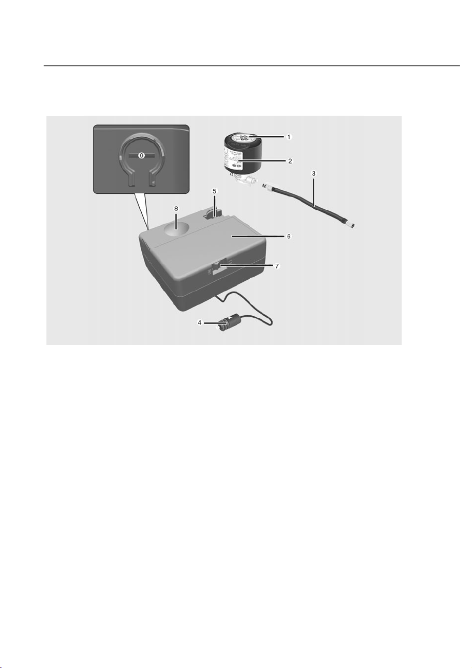
8-22
Emergency Situations
Components of the Tire Mobility Kit
ONE1081030
ONE1081030
M Speed restriction label
N Sealant bottle and label with speed restriction
O Filling hose
P Connectors and cable for power outlet direct connection
Q Holder for the sealant bottle
R Compressor
S ON/OFF switch
T Pressure gauge for displaying the tire inflation pressure
U Button for reducing the tire inflation pressure
Connectors, cable and connection hose are stored in the compressor housing.
Strictly follow the specified sequence, otherwise the sealant may escape under high
pressure.
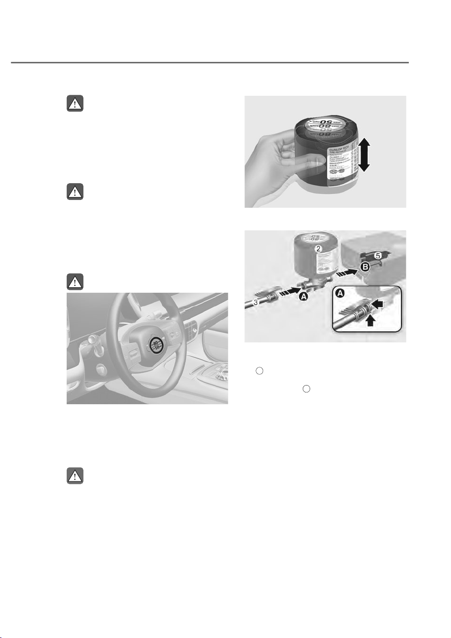
8-23
08
WARNING
Expired sealant
Do not use the Tire sealant after the
sealant has expired (for example, past
the expiration date on the sealant
container). This can increase the risk of
tire failure.
WARNING
Sealant
• Keep out of reach of children.
• Avoid contact with eyes.
• Do not swallow.
Using the Tire Mobility Kit
WARNING
ORS081007
ORS081007
Detach the speed restriction label M
from the sealant bottle N, and place
it in a highly visible place inside the
vehicle such as on the steering wheel to
remind the driver not to drive too fast.
CAUTION
If only the tire pressure needs to be
adjusted, refer to “How to Adjust Tire
Pressure” in this chapter. Before using
the Tire Mobility Kit, be fully aware of
the explanation on the sealant.
ORG3EV081022
ORG3EV081022
1. Shake the sealant bottle N.
ORS081022
ORS081022
2. Connect the filling hose O to the
sealant bottle N in the direction of
A
and connect the sealant bottle to
the sealant bottle holder Q in the
direction of
B
.
3. Ensure that the compressor is
switched OFF.
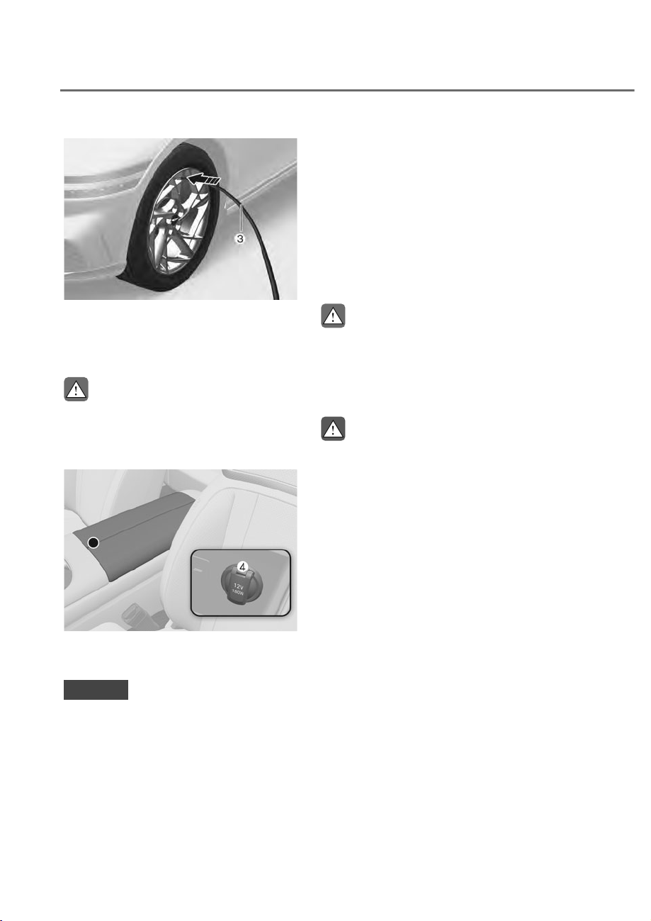
8-24
Emergency Situations
ORS081008L
ORS081008L
4. Unscrew the valve cap from the valve
of the defective wheel and screw the
filling hose O of the sealant bottle
onto the valve.
CAUTION
Securely install the sealant filling hose
to the valve. If not, sealant may flow
backward, possibly clogging the filling
hose.
ORS081009
ORS081009
5. Plug the compressor power cord P
into the vehicle power outlet.
NOTICE
Only use the front passenger side
power outlet when connecting the
power cord.
6. With the Engine Start/Stop button
in the ON position, switch on
the compressor and let it run for
approximately 5~7 minutes to fill the
sealant up to proper pressure. (refer
to the Tire and Wheels, chapter 2).
The inflation pressure of the tire after
filling is unimportant and will be
checked/ corrected later. Be careful
not to overinflate the tire and stay
away from the tire when filling it.
CAUTION
Tire pressure
Do not attempt to drive your vehicle if
the tire pressure is below 200 kPa (29
psi). This could result in an accident due
to sudden tire failure.
WARNING
Carbon monoxide
Do not leave your vehicle running in
a poorly ventilated area for extended
periods of time. Carbon monoxide
poisoning and suffocation can occur.
7. Switch off the compressor.
8. Detach the hoses from the sealant
bottle connector and from the tire
valve.
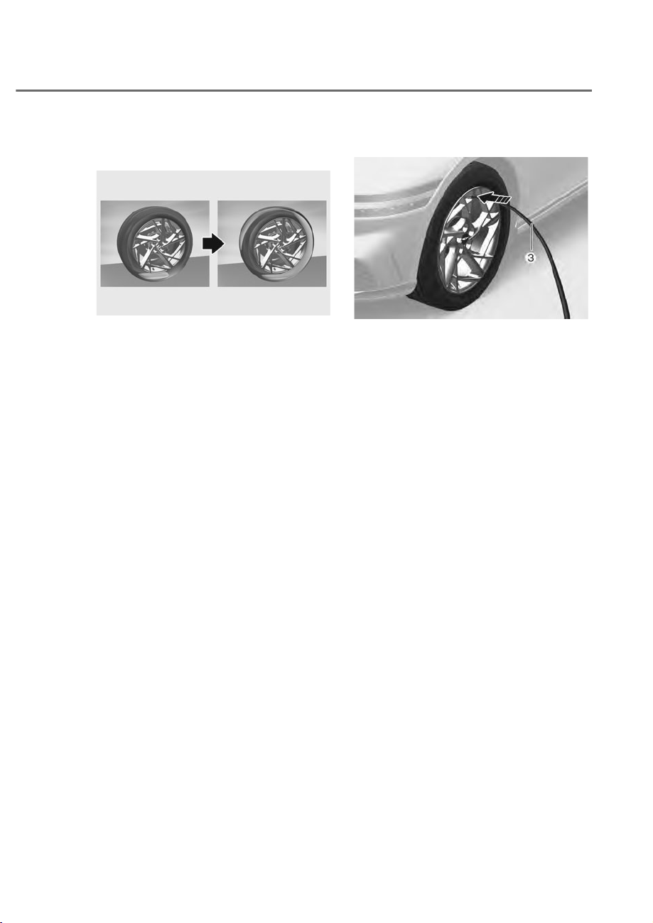
8-25
08
Return the Tire Mobility Kit to its storage
location in the vehicle.
ORS081024L
ORS081024L
9. Immediately drive approximately 4~6
miles (7~10 km or, about 10min) to
evenly distribute the sealant in the
tire.
Do not exceed a speed of 50 mph (80
km/h). If possible, do not fall below a
speed of 12 mph (20 km/h).
While driving, if you experience any
unusual vibration, ride disturbance or
noise, reduce your speed and drive with
caution until you can safely pull off of the
side of the road.
Call for road side service or towing.
ORS081008L
ORS081008L
10.
After driving approximately 4~6 miles
(7~10 km or about 10 min), stop at a
safety location.
11.
Connect the filling hose O of the
compressor directly to the tire valve.
12.
Connect between compressor and the
vehicle power outlet using the cable
and connectors.
13.
Adjust the tire inflation pressure to
the recommended tire inflation. With
the ignition switched on, proceed as
follows.
- To increase the inflation pressure:
Switch on the compressor. To
check the current inflation pressure
setting, briefly switch off the
compressor.
- To reduce the inflation pressure:
Press the button U on the
compressor.

8-26
Emergency Situations
NOTICE
Do not let the compressor run for more
than 10 minutes, otherwise the device
will overheat and may be damaged.
Information
The pressure gauge may show higher than
actual reading when the compressor is
running. To get an accurate tire pressure,
the compressor needs to be turned off.
CAUTION
If the inflation pressure is not
maintained, drive the vehicle a second
time, refer to step 9.
Then repeat steps 10 to 13.
Use of the TMK may be ineffectual for
tire damage larger than approximately
0.16 in (4 mm).
We recommend that you contact an
authorized retailer of Genesis Branded
products if the tire cannot be made
roadworthy with the Tire Mobility Kit.
WARNING
The tire inflation pressure must be at
least 32 psi (220 kPa). If it is not, do not
continue driving.
Call for road side service or towing.
CAUTION
Tire pressure sensor (if equipped with
TPMS)
The sealant on the tire pressure sensor
and wheel should be removed when
you replace the tire with a new one
and inspect the tire pressure sensors.
Have you get this done at an authorized
retailer of Genesis Branded products.
Information
When reinstalling the repaired or replaced
tire and wheel on the vehicle, tighten the
wheel bolt to 101~116 lbf ft (14~16 kgf m).
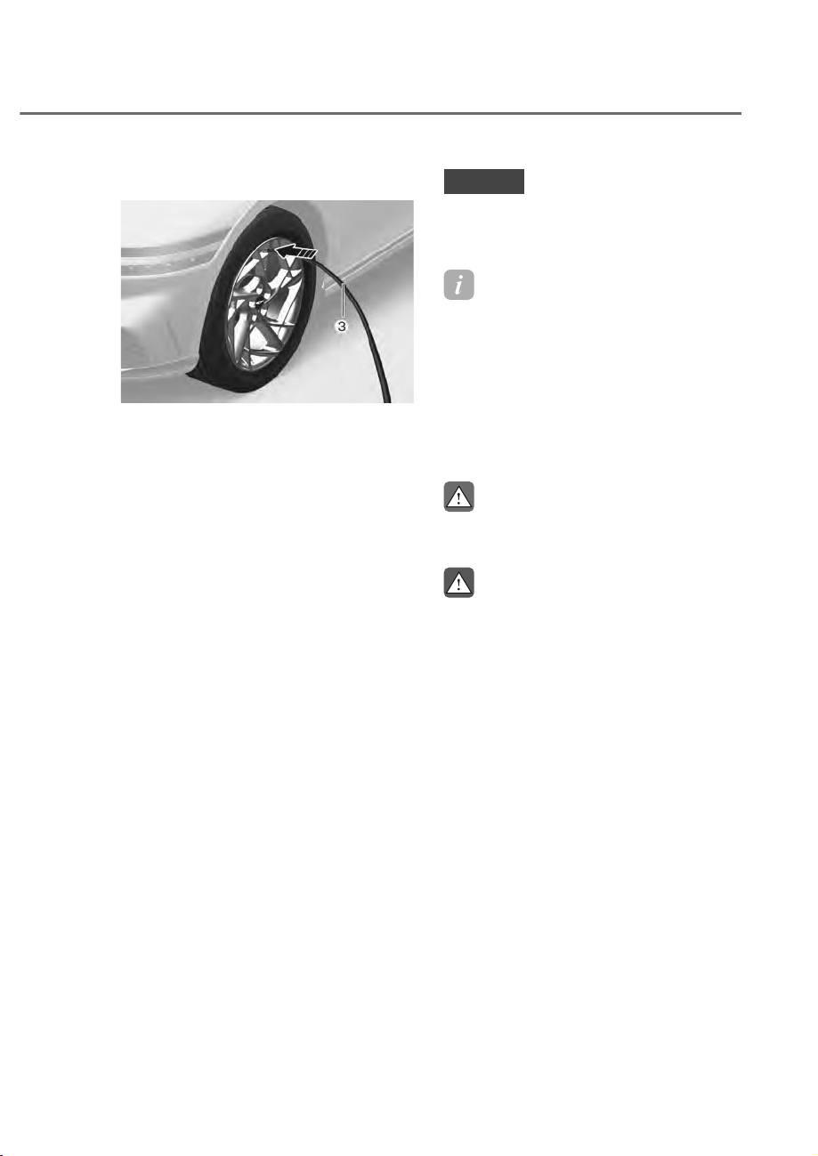
8-27
08
How to Adjust Tire Pressure
ORS081008L
ORS081008L
1. Park your vehicle in a safe location.
2. Connect the filling hose O of the
compressor directly to the tire valve.
3. Plug the compressor power cord into
the vehicle power outlet.
4. Adjust the tire inflation pressure to
the recommended tire inflation. With
the ignition switched on, proceed as
follows.
- To increase the inflation pressure:
Switch on the compressor. To
check the current inflation pressure
setting, briefly switch off the
compressor.
- To reduce the inflation pressure:
Press the button U on the
compressor.
NOTICE
Do not let the compressor run for more
than 10 minutes, otherwise the device
will overheat and may be damaged.
Information
• The pressure gauge may show
higher than actual reading when the
compressor is running. To get an
accurate tire reading, the compressor
needs to be turned off.
• When reinstalling the repaired or
replaced tire and wheel on the vehicle,
tighten the wheel bolt to 101~116 lbf ft
(14~16 kgf m).
CAUTION
Do not use the sealant when the tire
pressure only needs to be adjusted.
WARNING
The tire inflation pressure must be at
least 32 psi (220 kPa). If it is not, do not
continue driving.
Call for road side service or towing.
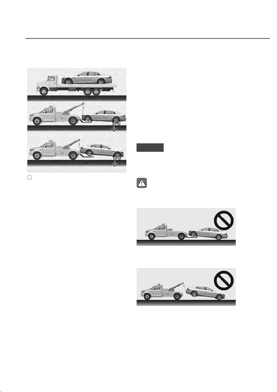
8-28
Emergency Situations
TOWING
Towing Service
ORS081010L
ORS081010L
A
: Dollies
If emergency towing is necessary,
we recommend having it done by an
authorized retailer of Genesis Branded
products or a commercial tow-truck
service.
Proper lifting and towing procedures
are necessary to prevent damage to
the vehicle. The use of wheel dollies or
flatbed is recommended.
For 2WD vehicles, it is acceptable to tow
the vehicle with the front wheels on the
ground (without dollies) and the rear
wheels off the ground.
If any of the loaded wheels or suspension
components are damaged or the vehicle
is being towed with the rear wheels on
the ground, use a towing dolly under the
rear wheels.
When being towed by a commercial tow
truck and wheel dollies are not used,
the rear of the vehicle should always be
lifted, not the front.
For AWD vehicles, it must be towed
with a wheel lift and dollies or flatbed
equipment with all the wheels off the
ground.
NOTICE
Do not lift the vehicle by the tow fitting
or body and chassis parts. Otherwise
the vehicle may be damaged.
CAUTION
• Do not tow the vehicle with the rear
wheels on the ground as this may
cause damage to the vehicle.
ORS081014L
ORS081014L
• Do not tow with sling-type
equipment. Use wheel lift or flatbed
equipment.
ORS081013L
ORS081013L
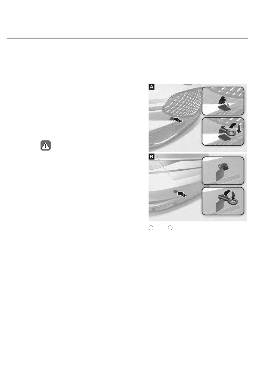
8-29
08
When towing your vehicle in an
emergency without wheel dollies:
1. Release EPB before turning off the
engine.
2. Press the Engine Start/Stop button to
the OFF position.
3. Change the gear to N (Neutral). For
more details, refer to “To stay in N
(Neutral) when vehicle is OFF” section
in chapter 6.
4. Press the Engine Start/Stop button to
the ACC position.
CAUTION
Failure to shift the gear to N (Neutral)
may cause internal damage to the
transmission.
Removable Towing Hook
1. Open the trunk, and remove the
towing hook from the tool case.
ORS081015
ORS081015
ORS081016
ORS081016
A
: Front,
B
: Rear
2. Remove the hole cover by pressing
the lower part of the cover on the
bumper.
3. Install the towing hook by turning it
clockwise into the hole until it is fully
secured.
4. Remove the towing hook and install
the cover after use.
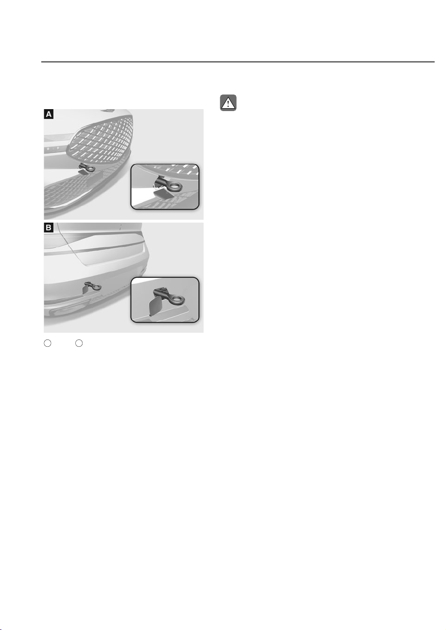
8-30
Emergency Situations
Emergency Towing
ORS081017
ORS081017
ORS081018
ORS081018
A
: Front,
B
: Rear
If towing is necessary, we recommend
you have it done by an authorized
retailer of Genesis Branded products or a
commercial tow truck service.
If towing service is not available in
an emergency, your vehicle may be
temporarily towed using a cable or chain
secured to the emergency towing hook
at the front (or rear) of the vehicle.
Use extreme caution when towing the
vehicle with a cable or chain. A driver
must be in the vehicle to steer it and
operate the brakes.
Towing in this manner may be done
only on hard-surfaced roads for a short
distance and at low speeds. Also, the
wheels, axles, power train, steering
and brakes must all be in good working
condition.
CAUTION
The driver must be in the vehicle for
steering and braking operations when
the vehicle is being towed. Passengers
other than the driver must not be in the
vehicle.
Always follow these emergency towing
precautions:
• Press the Engine Start/Stop button
to the ACC position so the steering
wheel is not locked.
• Shift the gear to N (Neutral).
• Release the parking brake.
• Depress the brake pedal with more
force than normal as you will have
reduced braking performance.
• More steering effort will be required
because the power steering system
will be disabled.
• Use a vehicle heavier than your own to
tow your vehicle.
• The drivers of both vehicles should
communicate with each other
frequently.
• Before emergency towing, check that
the hook is not broken or damaged.
• Fasten the towing cable or chain
securely to the hook.
• Do not jerk the hook. Apply steady
and even force.
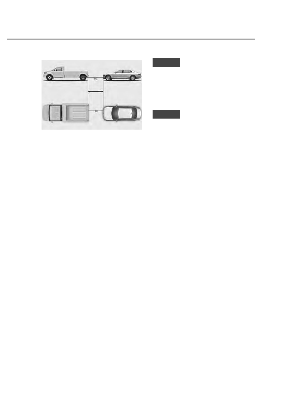
8-31
08
ORS081019L
ORS081019L
• Use a towing cable or chain less than
16 ft. (5 m) long. Attach a white or red
cloth (about 12 in. (30 cm) wide) in the
middle of the cable or chain for easy
visibility.
• Drive carefully so the towing cable or
chain remains tight during towing.
• Before towing, check the automatic
transmission for fluid leaks under your
vehicle. If the automatic transmission
fluid is leaking, flatbed equipment or a
towing dolly must be used.
NOTICE
Accelerate or decelerate the vehicle
in a slow and gradual manner while
maintaining tension on the tow rope
or chain to start or drive the vehicle,
otherwise tow hooks and the vehicle
may be damaged.
NOTICE
To avoid damage to your vehicle and
vehicle components when towing:
• Always pull straight ahead when
using the towing hooks. Do not pull
from the side or at a vertical angle.
• Do not use the towing hooks to pull
a vehicle out of mud, sand or other
conditions from which the vehicle
cannot be driven out under its own
power.
• Limit the vehicle speed to 10 mph
(15 km/h) and drive less than
1 mile (1.5 km) when towing to avoid
serious damage to the automatic
transmission.

9
9. Maintenance
Engine Compartment ....................................................................................... 9-3
Maintenance Services
...................................................................................... 9-4
Owner’s Responsibility ................................................................................................9-4
Owner Maintenance Precautions
................................................................................9-4
Owner Maintenance ......................................................................................... 9-5
Owner Maintenance Schedule ....................................................................................9-6
Scheduled Maintenance Services ................................................................... 9-7
Normal Maintenance Schedule ...................................................................................9-8
Maintenance Under Severe Usage Conditions
....................................................... 9-11
Explanation of Scheduled Maintenance Items .............................................9-13
Engine Oil
........................................................................................................9-15
Checking the Engine Oil Level .................................................................................. 9-15
Checking the Engine Oil and Filter
.......................................................................... 9-17
Engine Coolant/Liquid-Cooled Intercooler Coolant ....................................9-18
Checking the Coolant Level...................................................................................... 9-18
Changing Coolant
..................................................................................................... 9-20
Brake Fluid .......................................................................................................9-21
Checking the Brake Fluid Level ................................................................................ 9-21
Washer Fluid ....................................................................................................9-22
Checking the Washer Fluid Level ............................................................................. 9-22
Air Cleaner .......................................................................................................9-23
Filter Replacement .................................................................................................... 9-23
Cabin Air Filter .................................................................................................9-24
Filter Inspection......................................................................................................... 9-24
Filter Replacement
.................................................................................................... 9-24
Diffuser Catridge .............................................................................................9-26
Cartlidge Replacement ............................................................................................. 9-26
Wiper Blades ...................................................................................................9-27
Blade Inspection ....................................................................................................... 9-27
Blade Replacement
................................................................................................... 9-27
Battery .............................................................................................................9-29
Battery Usage Recommendations ........................................................................... 9-30
Battery Replacement
................................................................................................ 9-31
Battery Recharging
................................................................................................... 9-32
Reset Items
................................................................................................................ 9-33

9
Tires and Wheels .............................................................................................9-34
Tire Care ..................................................................................................................... 9-34
Recommended Cold Tire Inflation Pressures
.......................................................... 9-34
Check tire Inflation Pressure
.................................................................................... 9-35
Tire Rotation
.............................................................................................................. 9-36
Wheel Alignment and Tire Balance
.......................................................................... 9-37
Tire Replacement
...................................................................................................... 9-37
Wheel Replacement
.................................................................................................. 9-38
Tire Traction
............................................................................................................... 9-38
Tire Maintenance....................................................................................................... 9-38
Tire Sidewall Labeling
............................................................................................... 9-39
Tire Terminology and Definitions
............................................................................. 9-42
All Season Tires
.......................................................................................................... 9-45
Snow Tires.................................................................................................................. 9-45
Radial-Ply Tires
.......................................................................................................... 9-45
Low Aspect Ratio Tires
.............................................................................................. 9-46
Fuses ................................................................................................................ 9-47
Instrument Panel Fuse Replacement ....................................................................... 9-48
Engine Compartment Panel Fuse Replacement
..................................................... 9-49
Fuse/Relay Panel Description................................................................................... 9-50
Light Bulbs .......................................................................................................9-63
Headlight, Parking Lamp, Turn Signal Lamp, Daytime Running Light (DRL)
Replacement
............................................................................................................. 9-64
Side Repeater Lamp Replacement
.......................................................................... 9-64
Puddle Lamp Replacement
...................................................................................... 9-64
Rear Combination Lamp Replacement
................................................................... 9-65
High Mounted Stop Lamp Replacement
................................................................. 9-65
License Plate Lamp Replacement
............................................................................ 9-66
Interior light replacement
......................................................................................... 9-66
Appearance Care ............................................................................................9-68
Exterior Care .............................................................................................................. 9-68
Interior Care
............................................................................................................... 9-73
Emission Control System ................................................................................9-77
Crankcase Emission Control System ....................................................................... 9-77
Evaporative Emission Control System Including Onboard Refueling Vapor
Recovery (ORVR)
....................................................................................................... 9-77
Exhaust Emission Control System
............................................................................ 9-78
California Perchlorate Notice .........................................................................9-79
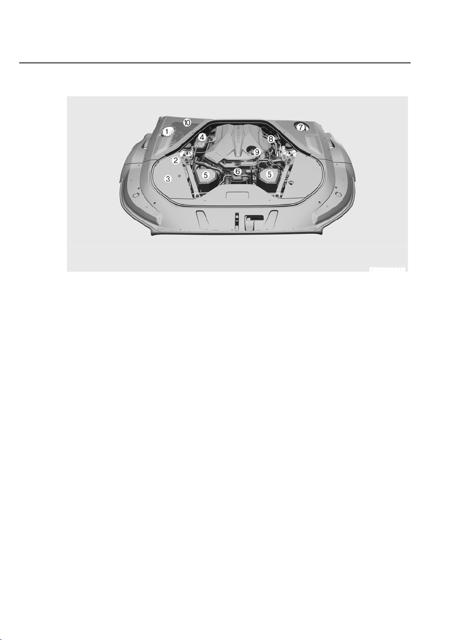
9-3
09
The actual engine compartment in the vehicle may differ from the illustration.
ORS092001N
1. Windshield washer fluid reservoir
2. Jumper terminal
3. Fuse box
4. Engine coolant reservoir
5. Air cleaner
6. Liquid-cooled intercooler coolant
reservoir
7. Brake fluid reservoir
8. Engine oil dipstick
9. Engine oil filler cap
10. Cabin air filter
ENGINE COMPARTMENT

9-4
Maintenance
You should exercise the utmost care
to prevent damage to your vehicle and
injury to yourself whenever performing
any maintenance or inspection
procedures.
We recommend you have your
vehicle maintained and repaired by an
authorized retailer of Genesis Branded
products. An authorized retailer of
Genesis Branded products meets
Genesis Branded Vehicle’s high service
quality standards and receives technical
support from Genesis Branded Vehicle in
order to provide you with a high level of
service satisfaction.
Owner’s Responsibility
Maintenance service and record
retention are the owner’s responsibility.
You should retain documents that show
proper maintenance has been performed
on your vehicle in accordance with
the scheduled maintenance service
charts shown on the following pages.
You need this information to establish
your compliance with the servicing
and maintenance requirements of your
vehicle warranties.
Detailed warranty information is
provided in your Owner’s Handbook &
Warranty Information booklet.
Repairs and adjustments required as a
result of improper maintenance or a lack
of required maintenance are not covered.
Owner Maintenance Precautions
Inadequate, incomplete or insufficient
servicing may result in operational
problems with your vehicle that could
lead to vehicle damage, an accident, or
personal injury. This chapter provides
instructions only for the maintenance
items that are easy to perform. Several
procedures can be done only by an
authorized retailer of Genesis Branded
products with special tools.
Your vehicle should not be modified
in any way. Such modifications may
adversely affect the performance, safety
or durability of your vehicle and may, in
addition, violate conditions of the limited
warranties covering the vehicle.
Certain modifications may also be in
violation of regulations established by
the U.S. Department of Transportation
and other federal or state agencies.
NOTICE
Improper owner maintenance during
the warranty period may affect
warranty coverage. For details, read
the separate Owner’s Handbook &
Warranty Information booklet provided
with the vehicle. If you’re unsure about
any service or maintenance procedure,
have it done by an authorized retailer of
Genesis Branded products.
MAINTENANCE SERVICES

9-5
09
WARNING
Performing maintenance work on a
vehicle can be dangerous. If you lack
sufficient knowledge and experience or
the proper tools and equipment to do
the work, have it done by an authorized
retailer of Genesis Branded products.
ALWAYS follow these precautions for
performing maintenance work:
ȉ Park your vehicle on level ground.
Shift the vehicle to P (Park), apply
the parking brake, and press the
Engine Start/Stop button to the OFF
position.
ȉ Block the tires (front and back) to
prevent the vehicle from moving.
Remove loose clothing or jewelry
that can become entangled in
moving parts.
ȉ If you must operate the engine
during maintenance, do so in an
outdoor area or in an area with
plenty of ventilation.
ȉ Keep flames, sparks, or smoking
materials away from the battery and
fuel-related parts.
WARNING
Touching metal parts
Do not touch metal parts
(including strut bars) while
the engine is operating or
hot. Doing so could result in
serious personal injury. Turn
the engine off and wait until
the metal parts cool down to
perform maintenance work on
the vehicle.
The following lists are vehicle checks and
inspections that should be performed
by the owner or an authorized retailer
of Genesis Branded products at the
frequencies indicated to help ensure
safe, dependable operation of your
vehicle.
Any adverse conditions should be
brought to the attention of your dealer as
soon as possible.
These Owner Maintenance vehicle
checks are generally not covered by
warranties and you may be charged for
labor, parts and lubricants used.
OWNER MAINTENANCE

9-6
Maintenance
Owner Maintenance Schedule
When you stop for fuel:
ȉ Check the coolant level in the engine
coolant reservoir or the liquid-cooled
intercooler coolant reservoir.
ȉ Check the windshield washer fluid
level.
ȉ Check for low or under-inflated tires.
WARNING
Be careful when checking your coolant
level if the motor compartment is hot.
This may result in coolant being blown
out of the opening and cause serious
burns and other injuries.
While operating your vehicle:
ȉ Note any changes in the sound of the
exhaust or any smell of exhaust fumes
in the vehicle.
ȉ Check for vibrations in the steering
wheel. Notice if there is any increased
steering effort or looseness in the
steering wheel, or change in its
straight-ahead position.
ȉ Notice if your vehicle constantly turns
slightly or “pulls” to one side when
traveling on smooth, level road.
ȉ When stopping, listen and check for
unusual sounds, pulling to one side,
increased brake pedal travel or “hard-
to-push” brake pedal.
ȉ If any slipping or changes in the
operation of your transmission occurs,
check the transmission fluid level.
ȉ Check the automatic transmission P
(Park) function.
ȉ Check the parking brake.
ȉ Check for fluid leaks under your
vehicle (water dripping from the air
conditioning system during or after
use is normal).
At least monthly:
ȉ Check coolant level in the engine
coolant reservoir.
ȉ Check the operation of all exterior
lights, including the stoplights, turn
signals and hazard warning flashers.
ȉ Check the inflation pressures of all
tires including the spare for tires that
are worn, show uneven wear, or are
damaged.
ȉ Check for loose wheel lug nuts.
At least twice a year: (for example,
every Spring and Autumn)
ȉ Check radiator, heater and air
conditioning hoses for leaks or
damage.
ȉ Check windshield washer spray and
wiper operation. Clean wiper blades
with a clean cloth dampened with
washer fluid.
ȉ Check headlight alignment.
ȉ Check muffler, exhaust pipes, shields
and clamps.
ȉ Check the seat belts for wear and
function.
At least once a year:
ȉ Clean body and door drain holes.
ȉ Lubricate door hinges and hood
hinges.
ȉ Lubricate door and hood locks and
latches.
ȉ Lubricate door rubber weather strips.
ȉ Check the air conditioning system.
ȉ Inspect and lubricate automatic
transmission linkage and controls.
ȉ Clean the battery and terminals.
ȉ Check the brake fluid level.

9-7
09
Follow Normal Maintenance Schedule if the vehicle is usually operated where none of the
following conditions apply. If any of the following conditions apply, you must follow the
Maintenance Under Severe Usage Conditions.
ȉ Repeated driving short distance of less than 5 miles (8 km) in normal temperature or less
than 10 miles (16 km) in freezing temperature
ȉ Extensive engine idling or low speed driving for long distances
ȉ Driving on rough, dusty, muddy, unpaved, graveled or salt-spread roads
ȉ Driving in areas using salt or other corrosive materials or in very cold weather
ȉ Driving in heavy dust conditions
ȉ Driving in heavy traffic area
ȉ Driving on uphill, downhill, or mountain roads
ȉ Using for towing or camping, and driving with loading on the roof
ȉ Driving as a patrol car, taxi, other commercial use of vehicle towing
ȉ Frequently driving under high speed or rapid acceleration/deceleration
ȉ Frequently driving in stop-and-go conditions
ȉ Engine oil usage which is not recommended (Mineral type, Semi-synthetic, Lower grade
spec, etc.)
If your vehicle is operated under the above conditions, you should inspect, replace or refill more
frequently than the following Normal Maintenance Schedule. After the periods or distance
shown in the chart, continue to follow the semi-synthetic, prescribed maintenance intervals.
NOTICE
After 10 years or 100,000 miles, we recommend to use severe maintenance schedule.
Information
ȉ As it is normal for engine oil to be consumed during driving, the engine oil level should be checked
on regular basis.
ȉ The engine oil change interval for normal operating conditions is based on the use of the
recommended engine specification. If the recommended engine oil specification is not used, then
replace the engine oil according to the maintenance schedule under severe operating conditions.
ȉ The vehicle may be equipped with the il Life Management System that predicts engine oil life
based on the driver’s driving history and alerts the driver to change engine oil.
- If the deterioration of the engine oil increases depending on the driver’s driving severity,
the remaining oil life alert appears on the instrument cluster before the normal engine oil
replacement interval. Have the engine oil and filter changed by an authorized retailer of Genesis
Branded product.
- il Life Management System works when the recommended engine oil is used. So, if
recommended engine oil is not used, replace the engine oil according to the maintenance schedule
under severe usage condition.
Also, check the amount of engine oil regularly as this system assumes that the engine oil is being
filled normally.
- Always reset the remaining engine oil life whenever the engine oil is changed. therwise, the
indication of remaining il life in the il Life Management System may not be accurate.
To reset the il hange Reminder, select ‘RESET’ from the infotainment system screen. Then,
select ‘Yes’ when the message “Has the engine oil been changed Press Yes to reset the oil life.”
appears on the screen.
- If there is no alert until the maximum maintenance interval, have the vehicle checked by an
authorized retailer of Genesis Branded product.
SCHEDULED MAINTENANCE SERVICES
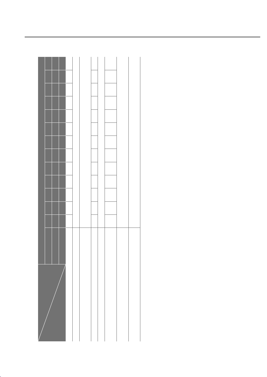
9-8
Maintenance
Normal Maintenance Schedule
MAINTENANCE
INTERVALS
MAINTENANCE
ITEM
Number of months or driving distance, whichever comes first
Months 12 24 36 48 60 72 84 96 108 120 132 144 156
Miles×1,000 8 16 24 32 40 48 56 64 72 80 88 96 104
Km×1,000 13 26 39 52 65 78 91 104 117 130 143 156 169
Engine oil and engine oil filter
*1 *2
RRRRRRRRRRRRR
Fuel additives
*3
Add every 8,000 miles (13,000 km) or 12 months
Air cleaner filter
Inspect every 8,000 miles (13,000 km) or 12 months,
replace every 24,000 miles (39,000 km) or 36 months
Spark plugs RR
Rotate tires Rotate tires every 8,000 miles (13,000 km) or 12 months
Cabin air filter
(for evaporator and blower unit)
RRRRRR
Drive belts
*4
At first, inspect at 48,000 miles (78,000 km) or 72 months,
after that, inspect every 8,000 miles (13,000 km) or 12 months
MHEV (Mild Hybrid Vehicle) belt *
4
(if equipped)
Inspect every 6,000 miles (10,000 km) or 12 months
Replace every 60,000 miles (100,000 km) or 48 months
I : Inspect and if necessary, adjust, correct, clean or replace.
R : Replace or change.
*1 :
Requires <API SN PLUS (or above) Full synthetic> grade engine oil. If a lower grade engine oil (mineral oil including Semi-
synthetic) is used, then the engine oil and engine oil filter must be replaced as indicated in maintenance under severe usage
conditions.
*2 :
Never add any additives to the engine oil. Engine oil additives can change the properties of engine oil and may cause serious
engine failure.
*3 :
If TOP TIER Detergent Gasoline is not available, one bottle of additive is recommended. Additives are available from your
authorized retailer of Genesis Branded products along with information on how to use them. Do not mix other additives.
*4 :
The drive belt should be replaced when cracks occur or tension is reduced.
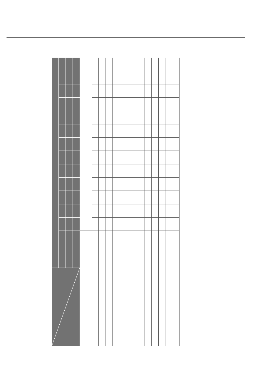
9-9
09
Normal Maintenance Schedule (Cont.)
MAINTENANCE
INTERVALS
MAINTENANCE
ITEM
Number of months or driving distance, whichever comes first
Months 12 24 36 48 60 72 84 96 108 120 132 144 156
Miles×1,000 8 16 24 32 40 48 56 64 72 80 88 96 104
Km×1,000 13 26 39 52 65 78 91 104 117 130 143 156 169
Engine coolant
At first, replace at 120,000 miles (200,000 km) or 120 months.
After that, replace every 25,000 miles (39,000 km) or 24 months
Battery condition IIIIIIIIIIIII
Brake lines, hoses and connections IIIIIIIIIIIII
Front brake disc/pads, calipers IIIIIIIIIIIII
Rear brake disc/pads IIIIIIIIIIIII
Steering gear rack, linkage and boots / lower arm ball
joint, upper arm ball joint
IIIIIIIIIIIII
Rear Wheel Steering (RWS) IIIIIIIIIIII
I
Drive Shaft IIIIIIIIIIIII
Suspension mounting bolts IIIIIIIIIIIII
Air conditioner refrigerant IIIIIIIIIIIII
Air conditioner compressor IIIIIIIIIIIII
Propeller shaft IIIIIIIIIIIII
Exhaust pipe and muffler IIIIIIIIIIIII
I : Inspect and if necessary, adjust, correct, clean or replace.
R : Replace or change.
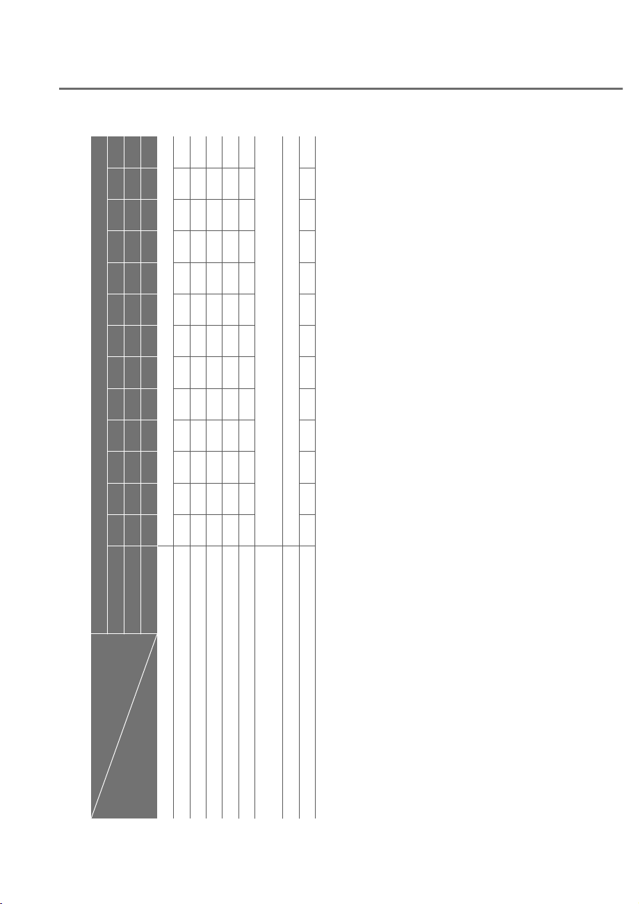
9-10
Maintenance
Normal Maintenance Schedule (Cont.)
MAINTENANCE
INTERVALS
MAINTENANCE
ITEM
Number of months or driving distance, whichever comes first
Months 12 24 36 48 60 72 84 96 108 120 132 144 156
Miles×1,000 8 16 24 32 40 48 56 64 72 80 88 96 104
Km×1,000 13 26 39 52 65 78 91 104 117 130 143 156 169
Automatic transmission fluid
*1
No check, No service required
Front (AWD) / rear differential oil
*2
III
Vapor hose, fuel filler cap and fuel tank IIIIII
Fuel tank air filter IIIIII
Fuel lines, hoses and connections IIIIII
Parking brake IIIIII
Brake fluid
Inspect every 8,000 miles (13,000 km) or 12 months,
Replace every 48,000 miles (78,000 km) or 48 months
Transfer case oil (AWD) No check, No service required
Air suspension IIIIIIIIIIIII
I : Inspect and if necessary, adjust, correct, clean or replace.
R : Replace or change.
*1 :
Use only the specified automatic transmission fluid. (Refer to “Recommended lubricants and capacities” section in chapter 2 or
the label in the engine compartment.)
*2 :
Front/rear differential oil should be changed anytime, front/rear differential have been submerged in water.
à Fuel filter is considered to be maintenance free but the quality of fuel used may impact the frequency of maintenance
needed. If there are some important safety matters like fuel flow restriction, surging, loss of power, hard starting
problem, etc. replace the fuel filter immediately regardless of maintenance schedule and consult an authorized retailer
of Genesis Branded products for details.

9-11
09
Maintenance Under Severe Usage Conditions
The following items must be serviced more frequently on cars mainly used under
severe driving conditions. Refer to the chart below for the appropriate maintenance
intervals.
R : Replace
I : Inspect and if necessary, adjust, correct, clean or replace
Maintenance item
Maintenance
operation
Maintenance intervals
Driving
condition
Engine oil and filter
*1
R
Replace every 5,000 miles
(8,000 km) or 6 months
D, H, I, L
MHEV (Mild Hybrid Vehicle)
belt (if equipped)
I
Inspect every 3,000 miles
(5,000 km) or 6 months
B, C, D,
E, I, K
R
Replace every 30,000 miles
(50,000 km) or 24 months
Air cleaner filter I
Inspect more frequently
depending on the condition
C, E
Spark plugs R
Replace more frequently
depending on the condition
A, B, F, G,
H, I, K
Steering gear rack, linkage and
boots
I
Inspect more frequently
depending on the condition
C, D, E,
F, G
Front suspension ball joints I
Inspect more frequently
depending on the condition
C, D, E,
F, G
Disc brakes and pads, calipers
and rotors
I
Inspect more frequently
depending on the condition
C, D, E, G,
H, J, K
Parking brake I
Inspect more frequently
depending on the condition
C, D, G, H
Drive Shaft I
Inspect more frequently
depending on the condition
C, D, E, F,
G, H, I, J
Cabin air filter R
Replace more frequently
depending on the condition
C, E, G
Automatic transmission fluid R
Replace every 60,000 miles
(100,000 km)
A, C, F, G,
H, I, J, K
Front differential oil (AWD) /
Rear differential oil
R
Replace every 72,000 miles
(120,000 km)
C, D, E, G,
H, I, J
Propeller shaft I
Inspect more frequently
depending on the condition
C, D, E, F,
G, H, I, J
Transfer case oil (AWD) No check, No service required
*1 :
Requires <API SN PLUS (or above) Full synthetic> grade engine oil. If a lower grade
engine oil (mineral oil including Semi-synthetic) is used, then the engine oil and engine
oil filter must be replaced as indicated in maintenance under severe usage conditions.

9-12
Maintenance
Severe driving conditions
A. Repeatedly driving short distance of less than 5 miles (8 km) in normal temperature
or less than 10 miles (16 km) in freezing temperature
B. Extensive engine idling or low speed driving for long distances
C. Driving on rough, dusty, muddy, unpaved, graveled or salt-spread roads
D. Driving in areas using salt or other corrosive materials or in very cold weather
E. Driving in heavy dust conditions
F. Driving in heavy traffic area
G. Driving on uphill, downhill, or mountain roads
H. Using for towing or camping, and driving with loading on the roof
I. Driving for patrol car, taxi, other commercial use of vehicle towing
J. Frequently driving under high speed or rapid acceleration/deceleration
K. Frequently driving in stop-and-go conditions
L. Engine oil usage which is not recommended (Mineral type, Semi-synthetic, Lower
grade spec, etc.)

9-13
09
Engine Oil and Filter
The engine oil and filter should be
changed at the intervals specified in the
maintenance schedule. If the vehicle
is being driven in severe conditions,
more frequent oil and filter changes are
required.
Drive Belts
Inspect all drive belts for evidence
of cuts, cracks, excessive wear or oil
saturation and replace if necessary.
Drive belts should be checked
periodically for proper tension and
adjusted as necessary.
Information
When you are inspecting the belt, turn the
engine off.
Fuel Lines, Fuel Hoses and
Connections
Check the fuel lines, fuel hoses and
connections for leakage and damage.
Have an authorized retailer of Genesis
Branded products replace any damaged
or leaking parts immediately.
Fuel Filter
The fuel filter is considered to be
maintenance free but periodic inspection
is recommended for this maintenance
depends on fuel quality. If there are
some important matters like fuel flow
restriction, surging, loss of power, hard
starting problem etc., replace the fuel
filter immediately. Have you consult an
authorized retailer of Genesis Branded
products for details.
Vapor Hose and Fuel Filler Cap
The vapor hose and fuel filler cap should
be inspected at those intervals specified
in the maintenance schedule. Make sure
a new vapor hose or fuel filler cap is
correctly replaced.
Air Cleaner Filter
We recommend that the air cleaner filter
be replaced by an authorized retailer of
Genesis Branded products.
Spark Plugs
Make sure to install new spark plugs of
the correct heat range.
When assembling parts, be sure to
wipe out foreign substances inside
and outside of the boot bottom of the
ignition coil and the insulator of the
spark plug with a soft cloth to prevent
contamination of the spark plug
insulator.
Cooling System
Check cooling system components, such
as radiator, coolant reservoir, hoses and
connections for leakage and damage.
Replace any damaged parts.
EXPLANATION OF SCHEDULED MAINTENANCE ITEMS

9-14
Maintenance
Engine Coolant/Liquid-Cooled
Intercooler Coolant
The coolant should be changed at the
intervals specified in the maintenance
schedule.
Automatic Transmission Fluid
Automatic transmission fluid should
not be checked under normal usage
conditions, the Automatic transmission
fluid should be changed by an authorized
retailer of Genesis Branded products
according to the maintenance schedule.
Information
Automatic transmission fluid color is red
when new.
As the vehicle is driven, the automatic
transmission fluid will begin to look
darker.
This is a normal condition. It does not
need to be replaced based on the color
change.
NOTICE
The use of a non-specified fluid could
result in transmission malfunction and
failure.
Use only specified automatic
transmission fluid. (Refer to
“Recommended Lubricants and
Capacities” section in chapter 2.)
Brake Hoses and Lines
Visually check for proper installation,
chafing, cracks, deterioration and any
leakage. Replace any deteriorated or
damaged parts immediately.
Brake Fluid
Check the brake fluid level in the brake
fluid reservoir. The level should be
between the MIN and the MAX marks
on the side of the reservoir. Use only
hydraulic brake fluid conforming to DOT
4 specification.
Brake Discs, Pads, Calipers and
Rotors
Check the pads, the disc, and the rotor
for any excessive wear-out. Inspect
calipers for any fluid leakage
Exhaust Pipe and Muffler
Visually inspect the exhaust pipes,
muffler and hangers for cracks,
deterioration, or damage. Start
the engine and listen carefully for
any exhaust gas leakage. Tighten
connections or replace parts as
necessary.
Propeller Shaft
Check the propeller shaft, boots, clamps,
rubber couplings and center-bearing
rubber for cracks, deterioration, or
damage. Replace any damaged parts
and if necessary, repack the grease.

9-15
09
ENGINE OIL
Suspension Mounting Bolts
Check the suspension connections for
looseness or damage. Retighten to the
specified torque.
Steering Gear box, Linkage &
Boots/Lower Arm Ball Joint
With the vehicle stopped and the engine
off, check for excessive free-play in the
steering wheel. Check the linkage for
bends or damage. Check the dust boots
and ball joints for deterioration, cracks,
or damage.
Replace any damaged parts.
Drive Shafts and Boots
Check the drive shafts, boots and clamps
for cracks, deterioration, or damage.
Replace any damaged parts and, if
necessary, repack the grease.
Air Conditioning Refrigerant
Check the air conditioning lines and
connections for leakage and damage.
Checking the Engine Oil Level
Engine oil is used for lubricating,
cooling, and operating various hydraulic
components in the engine. Engine oil
consumption while driving is normal,
and it is necessary to check and refill the
engine oil regularly. Also, check and refill
the oil level within the recommended
maintenance schedule to prevent
deterioration of oil performance.
Check the engine oil following the below
procedure.
1. Follow all of the oil manufacturer’s
precautions.
2. Be sure the vehicle is on the level
ground in P (Park) with the parking
brake set and the wheels blocked.
3. Turn the engine on and warm
the engine up until the coolant
temperature reaches a constant
normal temperature.
4. Turn the engine off, remove the oil
filler cap and pull the dipstick out.
Wait for 15 minutes for the oil to return
to the oil pan.
5. Wipe the dipstick clean and re-insert
it fully.
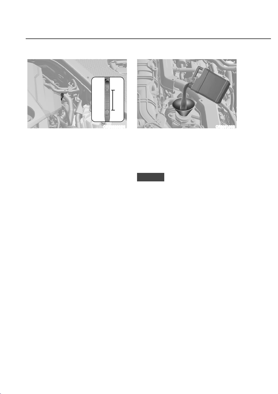
9-16
Maintenance
ORS092002N
6. Pull the dipstick out again and check
the level. The level should be between
F (Full) and L (Low).
ORS091003
7. If the oil level is below L, add enough
oil to bring the level to F.
Use only the specified engine oil (Refer
to “Recommended Lubricants and
Capacities” section in chapter 2).
NOTICE
To prevent damage to your engine:
ȉ Do not spill engine oil when adding
or changing engine oil. Wipe off
spilled oil immediately.
ȉ The engine oil consumption may
increase while you break in a new
vehicle and it will be stabilized after
driving 4,000 miles (6,000 km).
ȉ The engine oil consumption can be
affected by driving habits, climate
conditions, traffic conditions,
oil quality, etc. Therefore, it is
recommended that you inspect the
engine oil level regularly and refill it
if necessary.
9-17
09
Checking the Engine Oil and
Filter
ȉ The lubrication, rust prevention,
cooling, and cleaning effect of the
engine oil will gradually degrade
during its use. Have the engine oil
and filter changed by an authorized
retailer of Genesis Branded
products according to the Oil Life
Management System instructions
or the Maintenance Schedule at the
beginning of this chapter.
ȉ If the maintenance schedule to
replace engine oil is exceeded,
the engine oil performance may
deteriorate, and the engine condition
may be affected. Therefore, replace
the engine oil according to the
maintenance schedule.
ȉ To keep the engine in optimal
condition, use the recommended
engine oil and filter. If the
recommended engine oil and filter are
not used, replace it according to the
maintenance schedule under severe
usage conditions.
ȉ The purpose of the maintenance
schedule for engine oil replacement
is to prevent oil deterioration and it is
irrelevant to oil consumption. Check
and refill engine oil regularly.
Information
When the oil pressure is low due to
insufficient engine oil, the Engine
il Pressure (
) warning light will
illuminate. In addition, the enhanced
engine protection system, which limits
the engine's power is activated and the
Malfunction Indicator Lamp (
) will
illuminate when the vehicle is driven in
this state continuously. When oil pressure
is restored, the Engine il Pressure
warning light will turn off and the engine
power will no longer be limited.
However, for 3.5 T-GDI and 3.5 T-GDI
48 MHE , when the oil pressure is
restored, the warning light and the
enhanced engine protection system will
turn off after the engine is restarted.
CAUTION
The engine oil is very hot
immediately after the vehicle has
been driven and can cause burns
during replacement. Replace the
engine oil after the engine oil has
cooled down.
WARNING
CALIFORNIA PROPOSITION 65
WARNING
Engine oil contains chemicals known to
the State of California to cause cancer,
birth defects and reproductive harm.
Used engine oil may cause irritation or
cancer of the skin if left in contact with
the skin for prolonged periods of time.
Always protect your skin by washing
your hands thoroughly with soap and
warm water as soon as possible after
handling used oil.
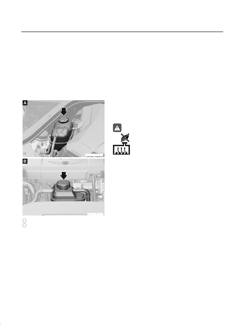
9-18
Maintenance
(1*,1(&22/$17/,48,'ʏ&22/(',17(5&22/(5&22/$17
The high-pressure cooling system has a
reservoir filled with year-round antifreeze
coolant. The reservoir is filled at the
factory.
Check the antifreeze protection and
coolant level at least once a year, at
the beginning of the winter season and
before traveling to a colder climate.
Checking the Coolant Level
ORS092004N
ORS091005
A
: Engine coolant,
B
: Liquid-cooled Intercooler coolant
Check the condition and connections
of all cooling system hoses and
heater hoses. Replace any swollen or
deteriorated hoses.
The coolant level should be filled
between the MAX and the MIN marks on
the side of the coolant reservoir when
the engine is cool.
If the coolant level is low, add enough
distilled (deionized) water to bring the
level to the MAX mark, but do not overfill.
If frequent additions are required, see an
authorized retailer of Genesis Branded
products for a cooling system inspection.
WARNING
Never remove the engine
coolant cap and/or liquid-
cooled intercooler coolant
cap or the drain plug while
the engine and radiator are
hot. Hot coolant and steam
may blow out under pressure,
causing serious injury.
Turn the vehicle off and wait until the
engine cools down. Use extreme care
when removing the engine coolant
cap and/or liquid-cooled intercooler
coolant cap. Wrap a thick towel around
it, and turn it counterclockwise slowly
to the first stop. Step back while the
pressure is released from the cooling
system. When you are sure all the
pressure has been released, press down
on the cap, using a thick towel, and
continue turning counterclockwise to
remove it.
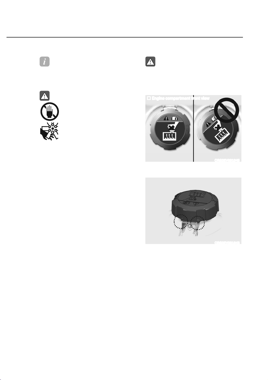
9-19
09
Information
The coolant level is influenced by the
engine temperature. Before checking or
refilling the coolant, turn the engine off.
WARNING
The electric motor for the
cooling fan may continue to
operate or start up when the
engine is not running and can
cause serious injury. Keep
hands, clothing and tools away
from the rotating fan blades of
the cooling fan.
Always turn off the vehicle unless the
vehicle has to be inspected with the
engine on. Be cautious as the cooling
fan may operate if the negative (-)
battery terminal is not disconnected.
WARNING
Make sure the coolant cap is properly
closed after refilling coolant. Otherwise
the engine could be overheated while
driving.
Engine compartment front view
ORG3EV091045
1. Check if the coolant cap label is
straight in front.
ORG3EV091043
2. Make sure that the tiny protrusions
inside the coolant cap are securely
interlocked.
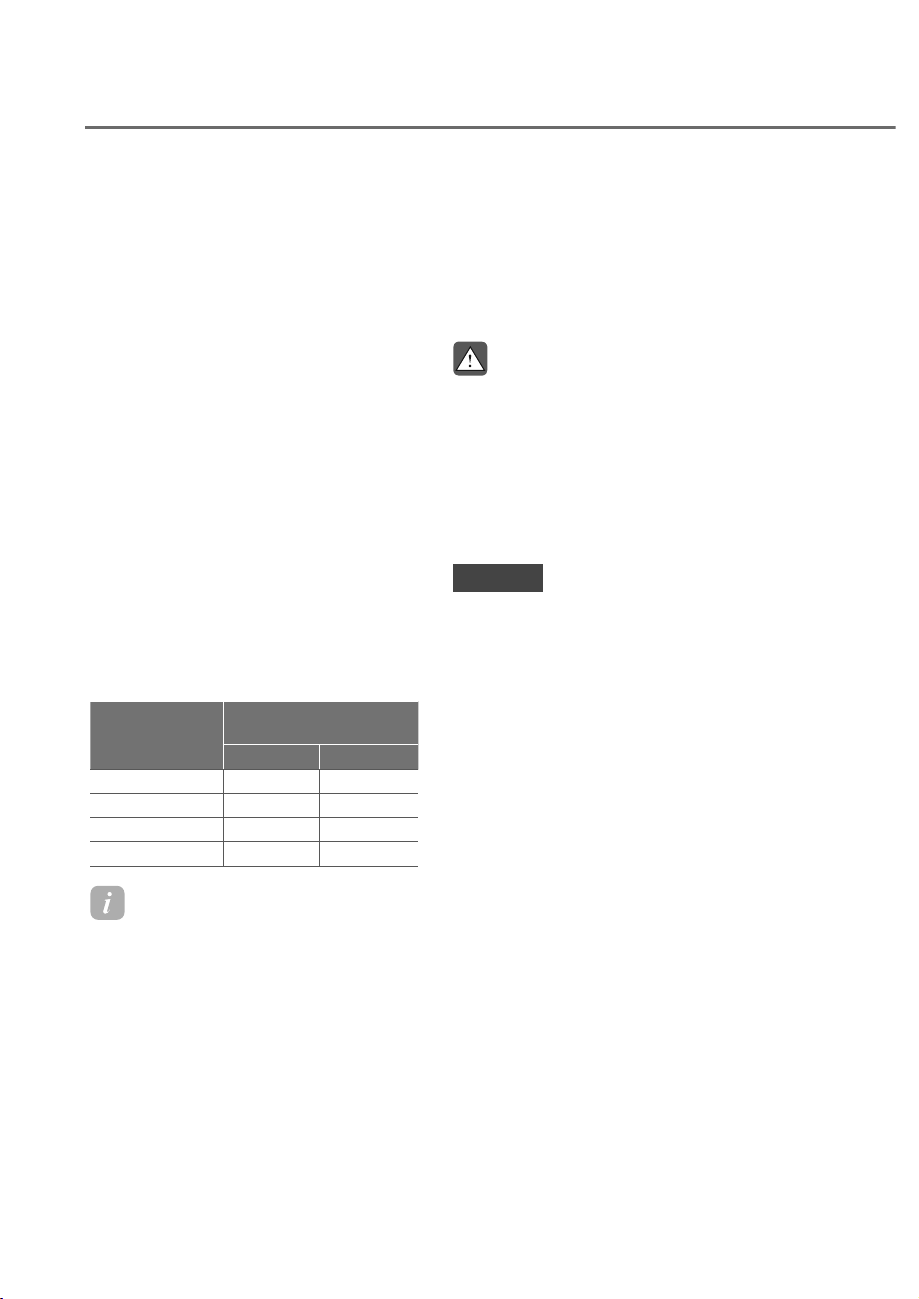
9-20
Maintenance
Recommended coolant
ȉ When adding coolant, use only
deionized water, distilled water or soft
water for your vehicle and never mix
hard water in the coolant filled at the
factory.
ȉ An incorrect coolant mixture can
result in severe malfunction or engine
damage.
ȉ The engine in your vehicle has
aluminum engine parts and must be
protected by an phosphate-based
ethylene glycol coolant to prevent
corrosion and freezing.
ȉ Do not use alcohol or methanol
coolant or mix them with the specified
coolant.
ȉ Do not use a solution that contains
more than 60% antifreeze or less than
35% antifreeze, which would reduce
the effectiveness of the solution.
For mixing percentage, refer to the
following table:
Ambient
Temperature
Mixture Percentage
(volume)
Antifreeze Water
5°F (-15°C) 35 65
-13°F (-25°C) 40 60
-31°F (-35°C) 50 50
-49°F (-45°C) 60 40
Information
If in doubt about the mix ratio, a 50%
water and 50% antifreeze mix is the
easiest to mix together as it will be the
same quantity of each. It is suitable to
use for most temperature ranges of -31 F
(-35 ) and higher.
Changing Coolant
Have coolant be changed by an
authorized retailer of Genesis Branded
products according to the Maintenance
Schedule at the beginning of this
chapter.
WARNING
Do not use engine coolant or antifreeze
in the washer fluid reservoir.
Engine coolant can severely obscure
visibility when sprayed on the
windshield and may cause loss of
vehicle control resulting in an accident.
Engine coolant may also cause damage
to paint and body trim.
NOTICE
To prevent damage to engine parts,
put a thick towel around the engine
coolant cap or liquid-cooled intercooler
coolant cap before refilling the
coolant to prevent the coolant from
overflowing into engine parts, such as
the alternator.
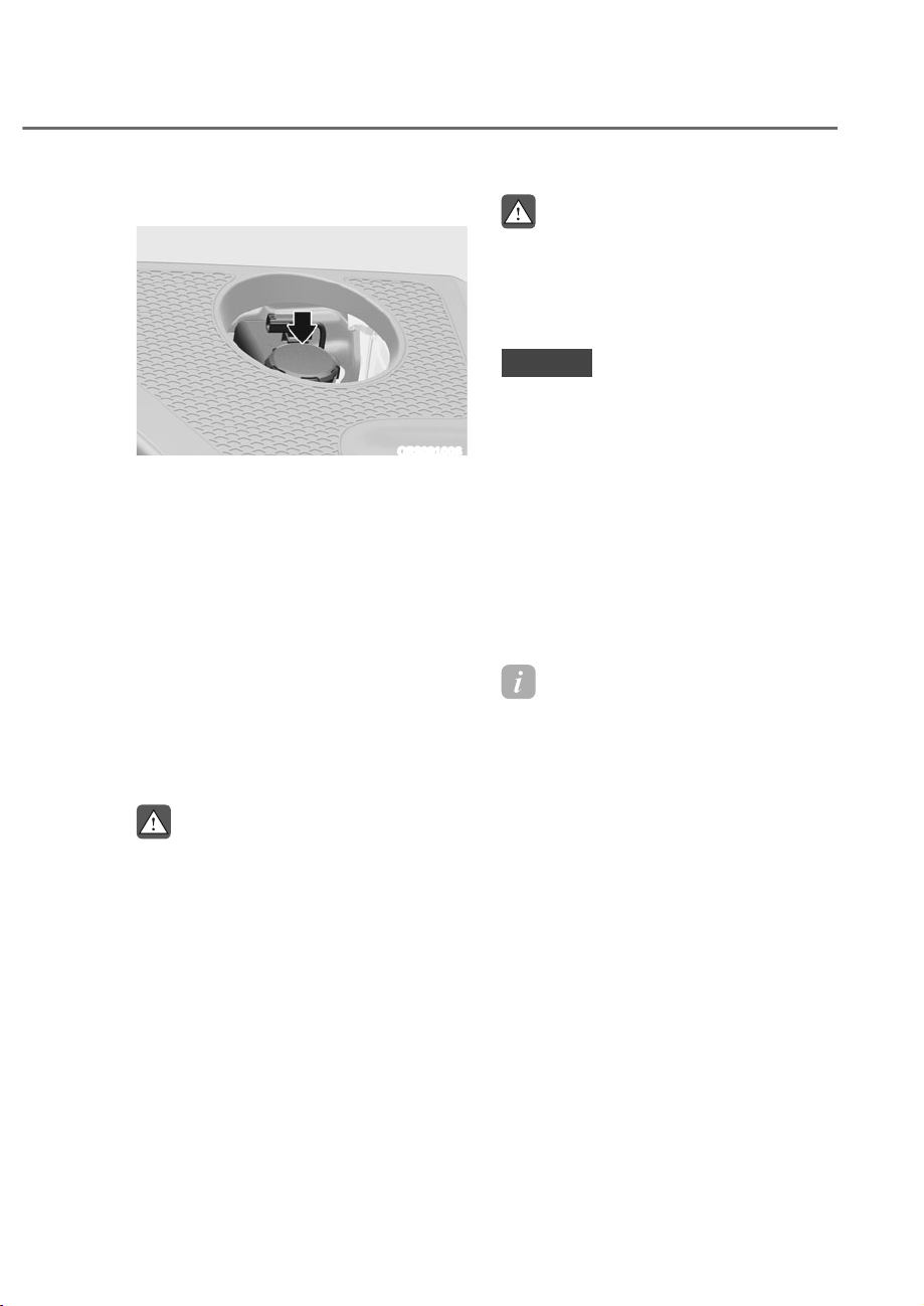
9-21
09
Checking the Brake Fluid Level
ORS091006
Check the fluid level in the reservoir
periodically. The fluid level should be
between MAX and MIN marks on the side
of the reservoir.
Before removing the reservoir cap and
adding brake fluid, clean the area around
the reservoir cap thoroughly to prevent
brake fluid contamination.
If the level is low, add the specified brake
fluid to the MAX level. The level will fall
with accumulated mileage. This is a
normal condition associated with the
wear of the brake linings. If the fluid level
is excessively low, have the brake system
checked by an authorized retailer of
Genesis Branded products.
WARNING
If the brake system requires frequent
additions of fluid this could indicate
a leak in the brake system. Have the
vehicle inspected by an authorized
retailer of Genesis Branded products.
WARNING
Do not let brake fluid enter into your
eyes. If brake fluid gets in your eyes,
flush your eyes with clean water for
at least 15 minutes and get immediate
medical attention.
NOTICE
ȉ Do not allow brake fluid to contact
the vehicle’s body paint, as it will
result in paint damage.
ȉ NEVER use brake fluid which has
been exposed to open air for an
extended time, as its quality cannot
be guaranteed. It should be disposed
of properly.
ȉ Do not use the wrong type of brake
fluid. A few drops of mineral based
oil such as engine oil in your brake
system can damage brake system
parts.
Information
Use only the specified brake fluid (refer
to “Recommended Lubricants and
apacities” section in chapter 2).
BRAKE FLUID
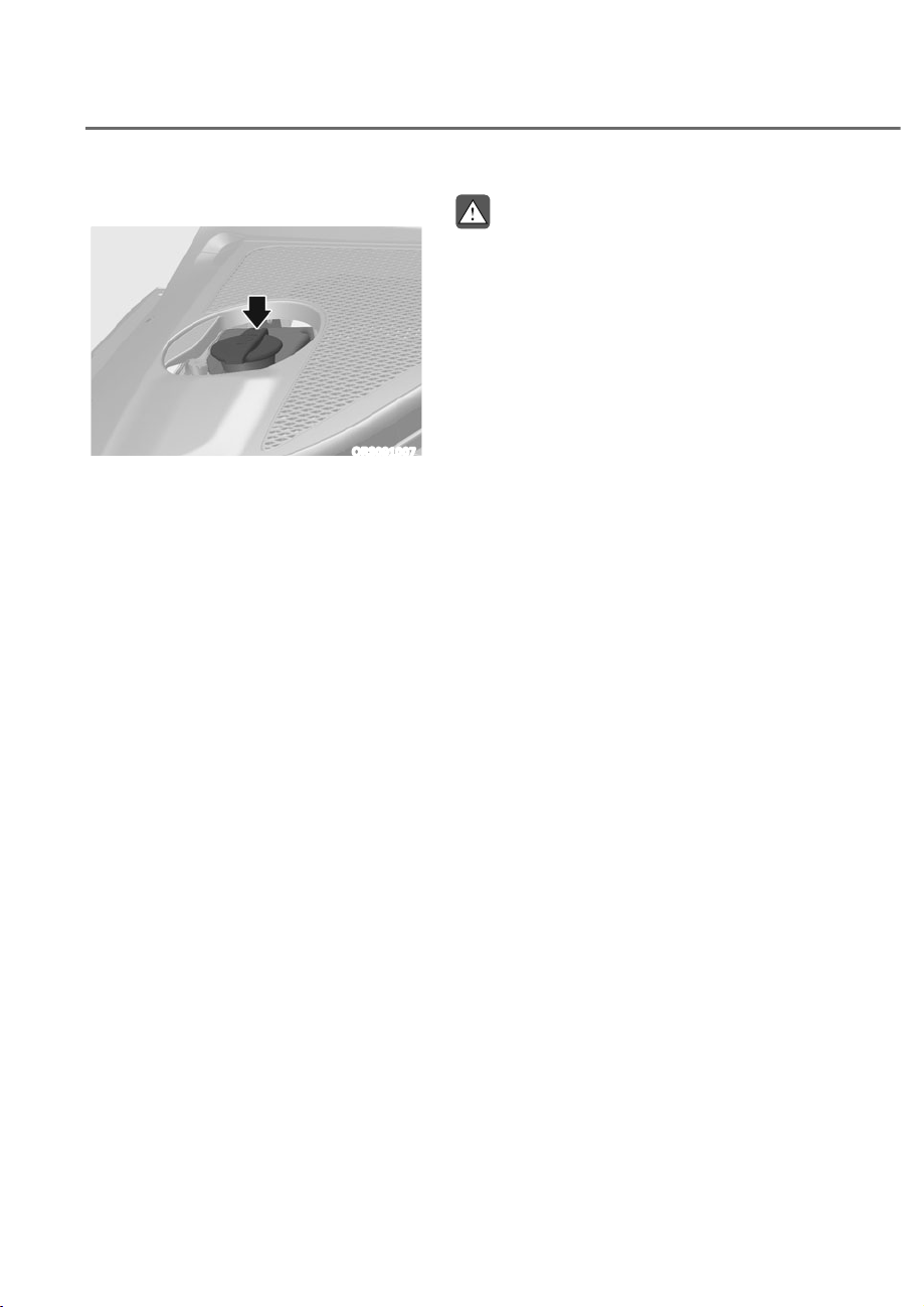
9-22
Maintenance
WASHER FLUID
Checking the Washer Fluid Level
ORS091007
Check the fluid level in the washer fluid
reservoir and add fluid if necessary. Plain
water may be used if washer fluid is not
available. However, use washer solvent
with antifreeze characteristics in cold
climates to prevent freezing.
WARNING
To prevent serious injury or death, take
the following safety precautions when
using washer fluid:
ȉ Do not use engine coolant or
antifreeze in the washer fluid
reservoir. Engine coolant can
severely obscure visibility when
sprayed on the windshield and
may cause loss of vehicle control
resulting in an accident or damage to
paint and body trim.
ȉ Do not allow sparks or flame to
contact the washer fluid or the
washer fluid reservoir. Washer fluid
may contain alcohol and can be
flammable.
ȉ Do not drink washer fluid and avoid
contact with skin. Washer fluid is
harmful to humans and animals.
ȉ Keep washer fluid away from
children and animals.
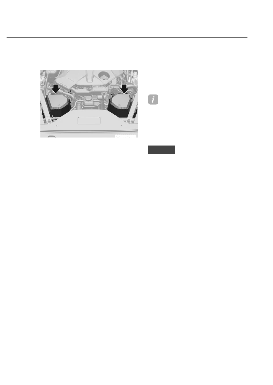
9-23
09
Filter Replacement
ORS092008N
Do not attempt to wash or to rinse it, as
water will damage the filter.
If soiled, the air cleaner filter must be
replaced.
Visit an authorized retailer of Genesis
Branded products to replace air cleaner
filter.
Replace the filter according to the
Maintenance Schedule.
Information
If the vehicle is operated in extremely
dusty or sandy areas, replace the air
cleaner filter more often than the
usual recommended intervals (Refer
to “Maintenance Under Severe Usage
onditions” section in this chapter).
NOTICE
ȉ Do not drive with the air cleaner filter
removed. This will result in excessive
engine wear.
ȉ When removing the air cleaner filter,
be careful that dust or dirt does not
enter the air intake, or damage may
result.
ȉ We recommend that you use parts
for replacement from an authorized
retailer of Genesis Branded products.
AIR CLEANER
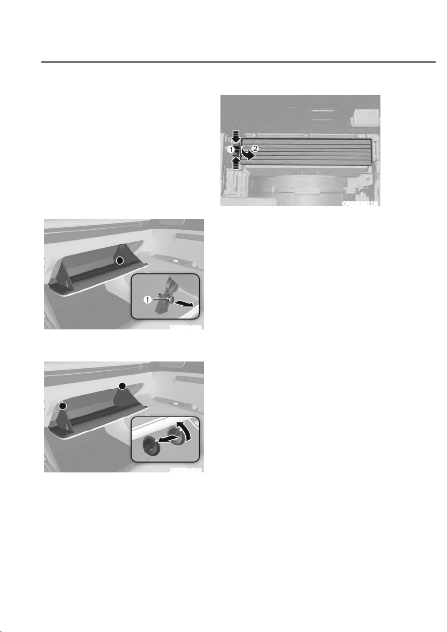
9-24
Maintenance
Filter Inspection
The cabin air filter should be replaced
according to the Maintenance Schedule.
If the vehicle is operated in severely air-
polluted cities or on dusty rough roads
for a long period, it should be inspected
more frequently and replaced sooner.
Replace the cabin air filter by following
the procedure below and be careful to
avoid damaging other components.
Filter Replacement
ORS091009
1. Open the glove box and remove the
support rod M.
ORS091010
2. Remove the stoppers on both sides to
allow the glove box to hang freely on
the hinges.
ORS092011N
3. Press and hold the lock M on the left
side of the cover.
4. Pull out N the cover
5. Replace the cabin air filter.
6. Reassemble in the reverse order of
disassembly.
CABIN AIR FILTER
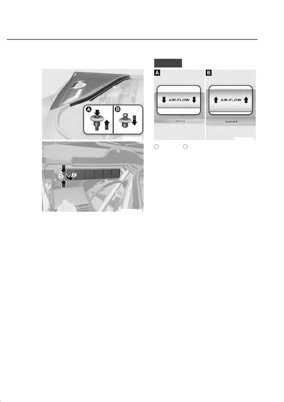
9-25
09
Engine Compartment
ORS091012
ORS092054N
1. Open the engine hood and remove
the cover of the air conditioning
assembly to locate the air filter.
2. Open the engine hood and remove
the cover of air conditioning unit.
3. Press and hold the lock M on the left
side of the cover.
4. Pull out N the cover
5. Replace the cabin air filter.
6. Reassemble in the reverse order of
disassembly.
NOTICE
ORS091061
A
: Glove box,
B
: Engine compartment
Install a new cabin air filter in the
correct direction to prevent noise and
reduce effectiveness.
ȉ Glove box: Install with the arrow
V\PEROIDFLQJGRZQZDUGɏ
ȉ Engine Compartment: Install with
WKHDUURZV\PEROIDFLQJXSɎ
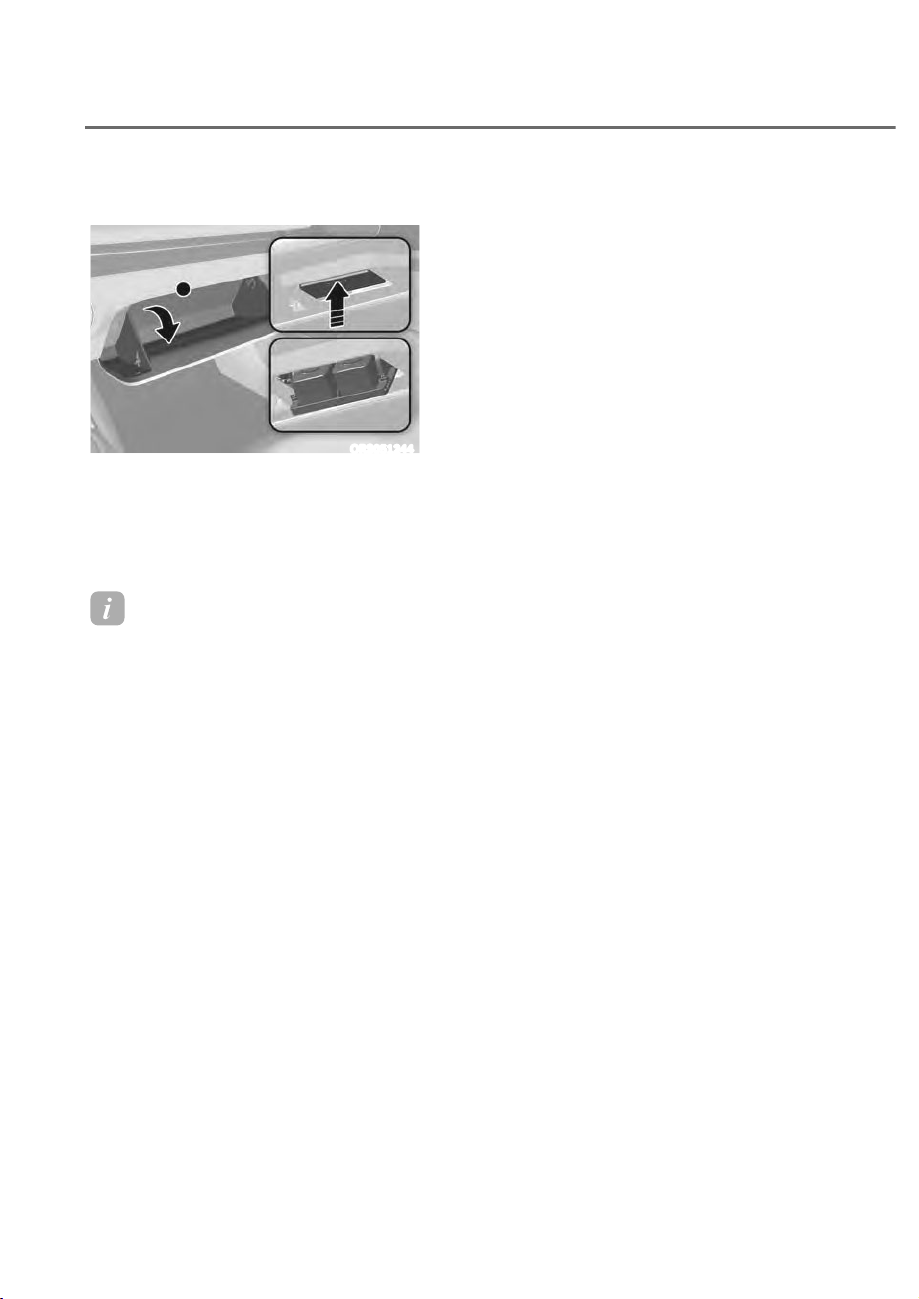
9-26
Maintenance
Cartlidge Replacement
ORS051244
1. Turn the engine off, and open the
glove box.
2. Press the upper part of the diffuser
tray.
3. Replace the cartridge.
Information
ȉ For smooth operation of diffuser, it is
recommended to install 2 cartridges.
ȉ If the cartridge is empty or diffuser
replacement alarm is displayed, replace
with a new cartridge.
ȉ The built-in diffuser may not work if
the cartridge is not installed properly.
heck whether the cartridge is installed
properly.
DIFFUSER CATRIDGE
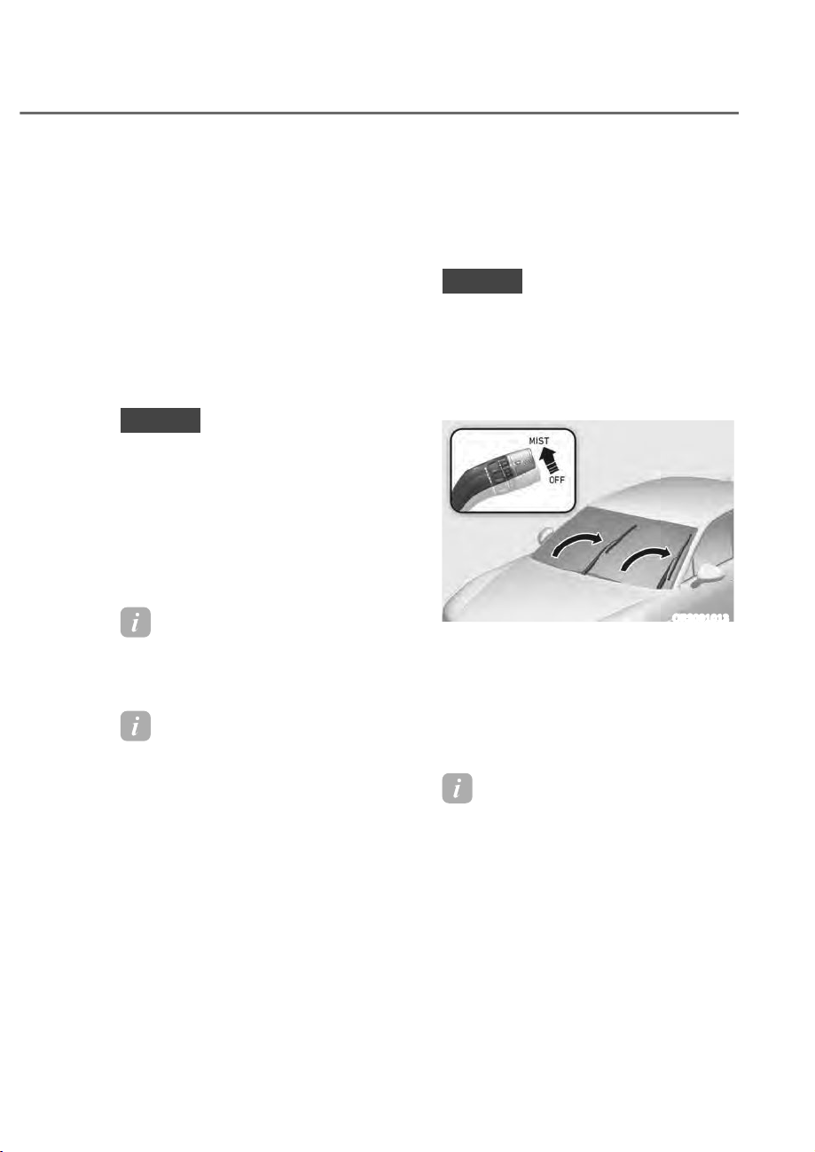
9-27
09
WIPER BLADES
Blade Inspection
Contamination of either the windshield
or the wiper blades with foreign matter
can reduce the effectiveness of the
windshield wipers.
Common sources of contamination are
insects, tree sap, and hot wax treatments
used by some commercial car washes. If
the blades are not wiping properly, clean
both the window and the blades with a
good cleaner or mild detergent, and rinse
thoroughly with clean water.
NOTICE
To prevent damage to the wiper blades,
arms or other components, do not:
ȉ Use gasoline, kerosene, paint
thinner, or other solvents on or near
them.
ȉ Attempt to move the wipers
manually.
ȉ Use non-specified wiper blades.
Information
ommercial hot waxes applied by
automatic car washes have been known to
make the windshield difficult to clean.
Information
Wiper blades are consumable items.
Normal wear of the wipers may not be
covered by your vehicle warranty.
Blade Replacement
When the wipers no longer clean
adequately, the blades may be worn or
cracked, and require replacement.
NOTICE
ȉ In order to prevent damage to the
hood and the wiper arms, the wiper
arms should only be lifted when in
the top wiping position.
ȉ Always return the wiper arms to the
windshield before driving.
ORS091013
1. Within 20 seconds of turning off the
engine, lift up and hold the wiper
lever to the MIST position for about 2
seconds until the wipers move to the
top wipe position.
2. At this time you can lift the wipers off
the windshield.
Information
This vehicle has a “hidden” wiper design
which means that the wipers cannot be
lifted manually when they are in their
bottom resting position.
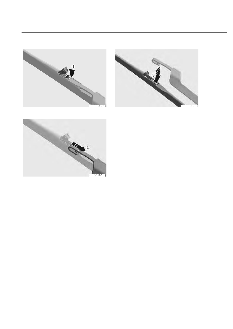
9-28
Maintenance
ORS091014
3. Lift up the wiper blade clip M.
ORS091015
4. Then slide the wiper blade down N.
ORS091016
5. Remove the wiper blade from the
wiper arm O.
6. Install the new blade assembly in the
reverse order of removal.
7. Return the wiper arm on the
windshield.
9-29
09
WARNING
To prevent SERIOUS INJURY or DEATH
to you or bystanders, always follow
these precautions when working near
or handling the battery:
Always read and follow
instructions carefully when
handling a battery.
Wear eye protection designed
to protect the eyes from acid
splashes.
Keep all flames, sparks, or
smoking materials away from
the battery.
Hydrogen is always present
in battery cells, is highly
combustible, and may explode
if ignited.
Keep batteries out of reach of
children.
Batteries contain sulfuric acid
which is highly corrosive. Do
not allow acid to contact your
eyes, skin or clothing.
If acid gets into your eyes, flush your
eyes with clean water for at least 15
minutes and get immediate medical
attention. If acid gets on your skin,
thoroughly wash the area. If you feel
pain or a burning sensation, get medical
attention immediately.
ȉ When lifting a plastic-cased battery,
excessive pressure on the case may
cause battery acid to leak. Lift with a
battery carrier or with your hands on
opposite corners.
ȉ Do not attempt to jump start your
vehicle if your battery is frozen.
ȉ NEVER attempt to recharge the
battery when the vehicle’s battery
cables are connected to the battery.
ȉ The electrical ignition system works
with high voltage. NEVER touch
these components with the engine
running or when the Engine Start/
Stop button is in the ON position.
ȉ Don’t remove the battery vent
hose. When the battery vent hose is
removed, insert it into the vent hole.
WARNING
CALIFORNIA PROPOSITION 65
WARNING
Battery posts, terminals, and related
accessories contain lead and lead
compounds, chemicals known to the
State of California to cause cancer,
birth defects and reproductive harm.
Batteries also contain other chemicals
known to the State of California
to cause cancer. Wash hands after
handling.
BATTERY
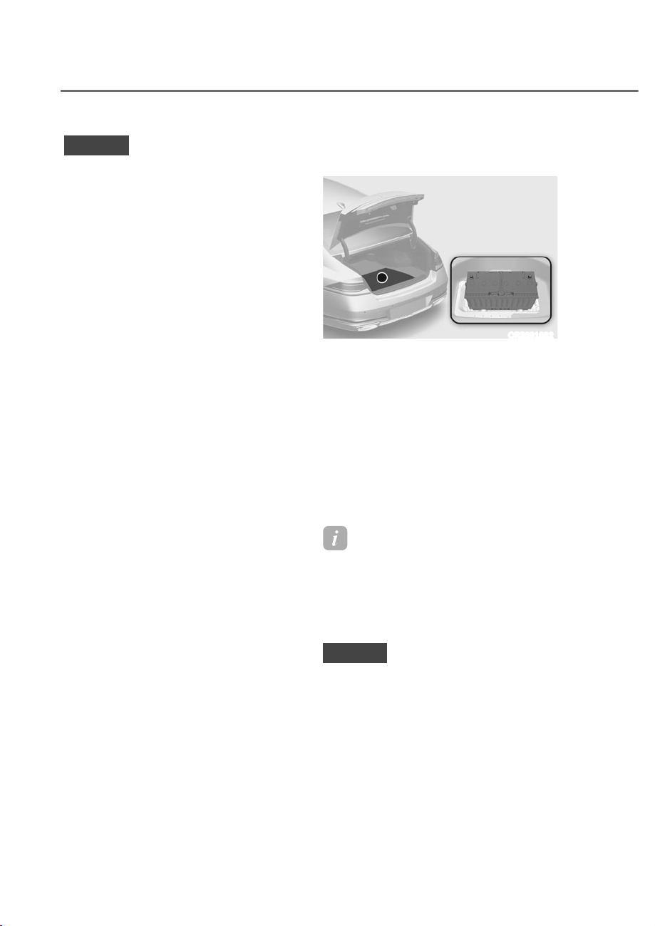
9-30
Maintenance
NOTICE
Always follow these instructions when
handling your vehicle's battery to
prevent damage to your battery:
ȉ When you do not use the vehicle for a
long time in a low temperature area,
disconnect the battery and keep it
indoors.
ȉ Always charge the battery fully to
prevent battery case damage in low
temperature areas.
ȉ Prevent liquid from wetting the
battery terminals. The performance
of the battery may be degraded, and
may cause injury. Be cautious when
loading liquid in the trunk.
ȉ Do not tilt the battery.
ȉ If you connect unauthorized
electronic devices to the battery, the
battery may be discharged. Never
use unauthorized devices.
Battery Usage
Recommendations
ORS091032
ȉ Keep the battery securely mounted.
ȉ Keep the battery top clean and dry.
ȉ Keep the terminals and connections
clean, tight, and coated with
petroleum jelly or terminal grease.
ȉ Rinse any spilled electrolyte from the
battery immediately with a solution of
water and baking soda.
ȉ If the vehicle is not going to be used
for an extended time, disconnect the
battery cables.
Information
For vehicles with power trunks, note
that the power trunk needs to be reset
after the battery has been replaced.
For more details, refer to "Power
Trunk" section in chapter 5.
NOTICE
Make sure the battery is installed
securely when the it is replaced. If the
battery vibrates while driving, the case
and electrode plate can be damaged.
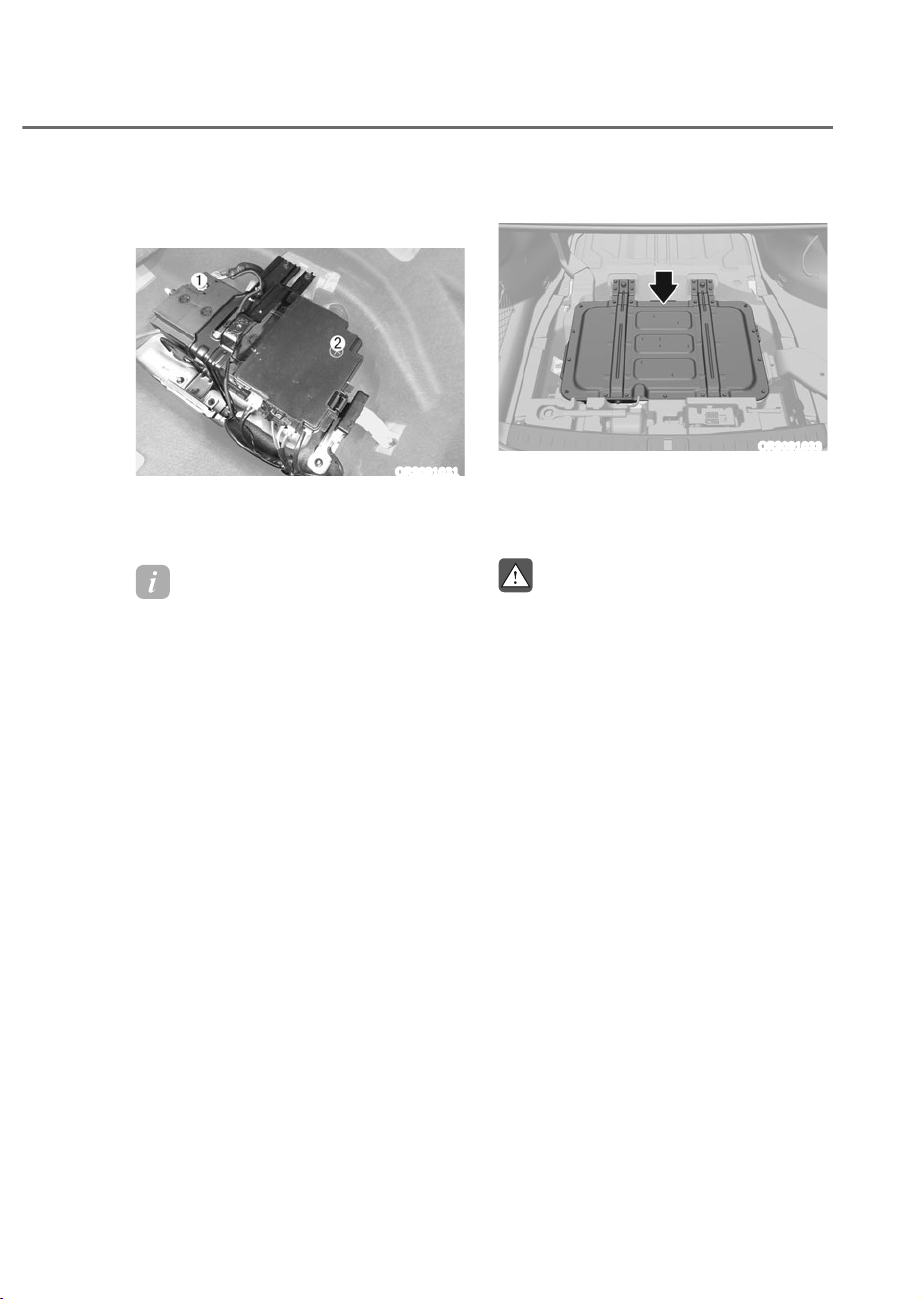
9-31
09
Battery Replacement
12 V battery
ORS091031
When replacing the battery, disconnect
the negative (-) cable M and remove the
positive (+) battery fuse box N.
Information
Mild hybrid vehicles have 48 battery
installed in the trunk, and 12 battery is
below the 48 battery.
48 V battery (if equipped)
ORS091033
Vehicles with a 48V battery have the
battery in the trunk. Have the battery
replaced by an authorized retailer of
Genesis Branded products.
WARNING
Inspections or repairs related to the
48 V battery must be performed by an
authorized retailer of Genesis Branded
products.

9-32
Maintenance
Battery Recharging
By battery charger
Should your vehicle's battery become
discharged either run the engine for
at least 60 minutes driving or at idle.
Alternatively you may connect a fully
automatic regulated charger to the
engine compartment front jumper posts
or at the battery in the trunk.
CAUTION
Do not use a manual unregulated
charger. It may cause the battery
to overheat and create a potential
hazard.
WARNING
Always follow these instructions when
recharging your vehicle’s battery to
avoid the risk of SERIOUS INJURY or
DEATH from explosions or acid burns:
ȉ Before performing maintenance or
recharging the battery, turn off all
accessories and stop the engine.
ȉ Keep all flames, sparks, or smoking
materials away from the battery.
ȉ Always work outdoors or in an area
with plenty of ventilation.
ȉ Wear eye protection when checking
the battery during charging.
ȉ The battery must be removed from
the vehicle and placed in a well
ventilated area.
ȉ Watch the battery during charging,
and stop or reduce the charging
rate if the battery cells begin boiling
violently.
ȉ The negative battery cable must
be removed first and installed last
when the battery is disconnected.
Disconnect the battery charger in the
following order:
1. Turn off the battery charger main
switch.
2. Unhook the negative clamp from
the negative battery terminal.
3. Unhook the positive clamp from
the positive battery terminal.
ȉ Always use a genuine Genesis Part
approved battery when you replace
the battery.

9-33
09
NOTICE
ȉ AGM battery
- Absorbent Glass Mat (AGM)
batteries are maintenance-free
and we recommend that the
AGM battery be serviced by an
authorized retailer of Genesis
Branded products. For charging
your AGM battery, use only fully
automatic battery chargers that
are specially developed for AGM
batteries.
- When replacing the AGM battery,
we recommend that you use
parts for replacement from an
authorized retailer of Genesis
Branded products.
- Do not open or remove the cap on
top of the battery. This may cause
leaks of internal electrolyte that
could result in severe injury.
ȉ Lithium battery (if equipped)
- Do not jump start other vehicles.
The lithium polymer type battery
installed in your vehicle may be
damaged.
- Do not connect external electrical
devices to the battery.
- When replacing the lithium
polymer battery, have the battery
replaced at an authorized retailer
of Genesis Branded products.
By jump starting
After a jump start from a good battery,
drive the vehicle for 20-30 minutes
before it is shutoff. The vehicle may
not restart if you shut it off before the
battery had a chance to adequately
recharge. See “Jump Starting” in chapter
8 for more information on jump starting
procedures.
Information
An inappropriately disposed
battery can be harmful to the
environment and human health.
Dispose of the battery according
to your local law(s) or regulation.
Reset Items
The following items may need to be reset
after the battery has been discharged or
the battery has been disconnected.
ȉ Fuel economy/Driving info/Since
refueling/Accumulated info (items in
Normal view) (see chapter 4)
ȉ Integrated memory system (see
chapter 5)
ȉ Power window (see chapter 5)
ȉ Sunroof (see chapter 5)
ȉ Power trunk (see chapter 5)
ȉ Climate control system (see chapter 5)
ȉ Rear door window shade (see chapter
5)
ȉ Clock (see Infotainment system
manual)
ȉ Infotainment system (see
Infotainment system manual)
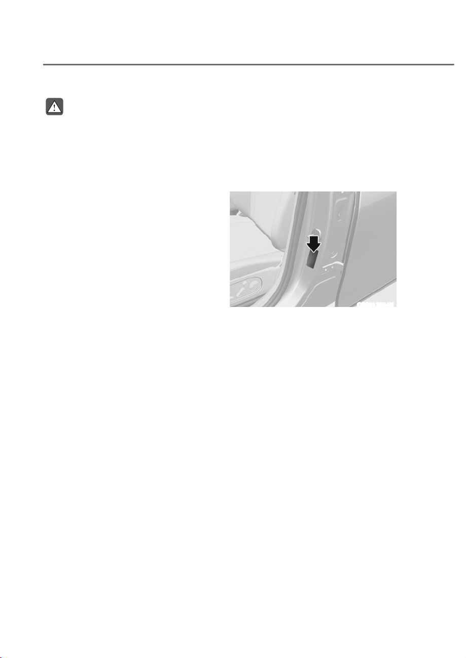
9-34
Maintenance
WARNING
Tire failure may cause loss of
vehicle control resulting in an
accident. To reduce risk of SERIOUS
INJURY or DEATH, take the
following precautions:
ȉ Inspect your tires monthly for
proper inflation as well as wear
and damage.
ȉ The recommended cold tire
pressure for your vehicle can be
found in this manual and on the
tire label located on the driver’s
side center pillar. Always use a
tire pressure gauge to measure
tire pressure. Tires with too
much or too little pressure wear
unevenly causing poor handling.
ȉ Check the pressure of the
spare every time you check the
pressure of the other tires on
your vehicle.
ȉ Replace tires that are worn, show
uneven wear, or are damaged.
Worn tires can cause loss of
braking effectiveness, steering
control, or traction.
ȉ ALWAYS replace tires with the
same size, type, construction and
tread pattern as each tire that
was originally supplied with this
vehicle. Using tires and wheels
other than the recommended
sizes could cause unusual
handling characteristics, poor
vehicle control, or negatively
affect your vehicle’s Anti-Lock
Brake System (ABS) resulting in a
serious accident.
Tire Care
For proper maintenance, safety, and
maximum fuel economy, you must
always maintain recommended
tire inflation pressures and stay
within the load limits and weight
distribution recommended for your
vehicle.
ORS012024N
All specifications (sizes and
pressures) can be found on a label
attached to the driver’s side center
pillar.
Recommended Cold Tire
Inflation Pressures
All tire pressures (including the
spare) should be checked when the
tires are cold. “Cold tires” means the
vehicle has not been driven for at
least three hours or driven less than
one mile (1.6 km).
Warm tires normally exceed
recommended cold tire pressures
by 4 to 6 psi (28 to 41 kPa). Do not
release air from warm tires to adjust
the pressure or the tires will be
under-inflated. For recommended
inflation pressure, refer to “Tire and
Wheels” section in chapter 2.
TIRES AND WHEELS

9-35
09
WARNING
Recommended pressures must be
maintained for the best ride, vehicle
handling, and minimum tire wear.
Over-inflation or under-inflation
can reduce tire life, adversely
affect vehicle handling, and lead to
sudden tire failure that could result
in loss of vehicle control resulting in
an accident.
Severe under-inflation can lead
to severe heat build-up, causing
blowouts, tread separation and
other tire failures that can result in
the loss of vehicle control resulting
in an accident. This risk is much
higher on hot days and when
driving for long periods at high
speeds.
CAUTION
ȉ Under-inflation results in
excessive wear, poor handling
and reduced fuel economy.
Wheel deformation is also
possible. Keep your tire pressures
at the proper levels. If a tire
frequently needs refilling, have it
checked by an authorized retailer
of Genesis Branded products.
ȉ Over-inflation produces a harsh
ride, excessive wear at the center
of the tire tread, and a greater
possibility of damage from road
hazards.
Check tire Inflation Pressure
Check your tires, including the spare
tire(if equipped), once a month or
more.
How to check
Use a good quality tire pressure
gauge to check tire pressure. You
can not tell if your tires are properly
inflated simply by looking at them.
Radial tires may look properly
inflated when they are under-
inflated.
Remove the valve cap from the tire
valve stem. Press the tire gauge
firmly onto the valve to get a
pressure measurement. If the cold
tire inflation pressure matches the
recommended pressure on the tire
and loading information label, no
further adjustment is necessary. If
the pressure is low, add air until you
reach the recommended pressure.
Make sure to put the valve caps
back on the valve stems. Without
the valve cap, dirt or moisture could
get into the valve core and cause
air leakage. If a valve cap is missing,
install a new one as soon as possible.
If you overfill the tire, release air by
pushing on the metal stem in the
center of the tire valve. Recheck the
tire pressure with the tire gauge. Be
sure to put the valve caps back on
the valve stems. Without the valve
cap, dirt or moisture could get into
the valve core and cause air leakage.
If a valve cap is missing, install a new
one as soon as possible.
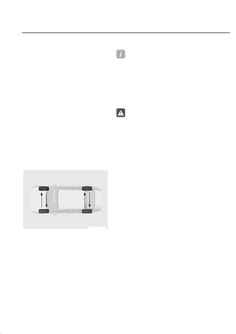
9-36
Maintenance
Tire Rotation
To equalize tread wear, Genesis
Branded Vehicle recommends that
the tires be rotated according to the
maintenance schedule or sooner if
irregular wear develops.
During rotation, check the tires for
correct balance.
When rotating tires, check for uneven
wear and damage. Abnormal wear
is usually caused by incorrect tire
pressure, improper wheel alignment,
out-of-balance wheels, severe braking
or severe cornering. Look for bumps or
bulges in the tread or side of the tire.
Replace the tire if you find any of these
conditions. Replace the tire if fabric or
cord is visible. After rotation, be sure to
bring the front and rear tire pressures
to specification and check wheel bolt
tightness (proper torque is 101~116
lbf·ft [14-16 kgf·m].
ORS091056L
Disc brake pads should be inspected
for wear whenever tires are rotated.
Information
The outside and inside of the
unsymmetrical tire is distinguishable.
When installing an unsymmetrical
tire, be sure to install the side marked
“outside” face the outside. If the side
marked “inside” is installed on the
outside, it will have a negative effect
on vehicle performance.
WARNING
ȉ Do not use the compact spare
tire for tire rotation.
ȉ Do not mix bias ply and radial ply
tires under any circumstances.
This may cause unusual handling
characteristics that may cause
loss of vehicle control resulting in
an accident.
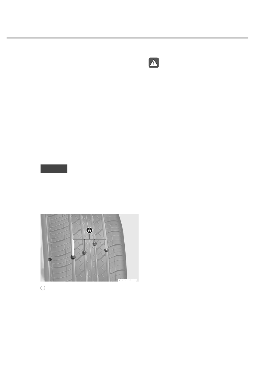
9-37
09
Wheel Alignment and Tire
Balance
The wheels on your vehicle were
aligned and balanced carefully at the
factory to give you the longest tire
life and best overall performance.
In most cases, you will not need to
have your wheels aligned again.
However, if you notice unusual tire
wear or your vehicle pulling one way
or the other, the alignment may need
to be reset.
If you notice your vehicle vibrating
when driving on a smooth road, your
wheels may need to be rebalanced.
NOTICE
Incorrect wheel weights can
damage your vehicle’s aluminum
wheels. Use only approved wheel
weights.
Tire Replacement
ORS091057
A
: Tread wear indicator
If the tire is worn evenly, a tread wear
indicator will appear as a solid band
across the tread. This shows there is
less than 1/16 inch (1.6 mm) of tread
left on the tire. Replace the tire when
this happens.
Do not wait for the band to appear
across the entire tread before
replacing the tire.
WARNING
To reduce the risk of DEATH or
SERIOUS INJURY:
ȉ Replace tires that are worn, show
uneven wear, or are damaged.
Worn tires can cause loss of
braking effectiveness, steering
control, and traction.
ȉ Always replace tires with the
same size as each tire that was
originally supplied with this
vehicle. Using tires and wheels
other than the recommended
sizes could cause unusual
handling characteristics, poor
vehicle control, or negatively
affect your vehicle’s Anti-Lock
Brake System (ABS) resulting in a
serious accident.
ȉ When replacing tires (or wheels),
it is recommended to replace
the two front or two rear tires (or
wheels) as a pair. Replacing just
one tire can seriously affect your
vehicle’s handling.
ȉ Tires degrade over time, even
when they are not being used.
Regardless of the remaining
tread, Genesis Branded Vehicle
recommends that tires be
replaced after six (6) years of
normal service.
ȉ Heat caused by hot climates or
frequent high loading conditions
can accelerate the aging process.
Failure to follow this warning
may cause sudden tire failure,
which could lead to a loss of
vehicle control resulting in an
accident.

9-38
Maintenance
Compact spare tire (if equipped)
replacement
A compact spare tire has a shorter
tread life than a regular size tire.
Replace it when you can see the
tread wear indicator bars on the tire.
The replacement compact spare tire
should be the same size and design
tire as the one provided with your
new vehicle and should be mounted
on the same compact spare tire
wheel. The compact spare tire is
not designed to be mounted on a
regular size wheel, and the compact
spare tire wheel is not designed for
mounting a regular size tire.
WARNING
The original tire should be repaired
or replaced as soon as possible to
avoid failure of the compact spare
tire and loss of vehicle control
resulting in an accident. The
compact spare tire is for emergency
use only. Do not operate your
vehicle over 50 mph (80 km/h)
when using the compact spare tire.
Wheel Replacement
When replacing the metal wheels
for any reason, make sure the new
wheels are equivalent to the original
factory units in diameter, rim width
and offset.
Tire Traction
Tire traction can be reduced if you
drive on worn tires, tires that are
improperly inflated or on slippery
road surfaces. Tires should be
replaced when tread wear indicators
appear. To reduce the possibility of
losing control, slow down whenever
there is rain, snow or ice on the road.
Tire Maintenance
In addition to proper inflation,
correct wheel alignment helps to
decrease tire wear. If you find a tire
is worn unevenly, have your dealer
check the wheel alignment.
When you have new tires installed,
make sure they are balanced. This
will increase vehicle ride comfort
and tire life. Additionally, a tire
should always be rebalanced if it is
removed from the wheel.
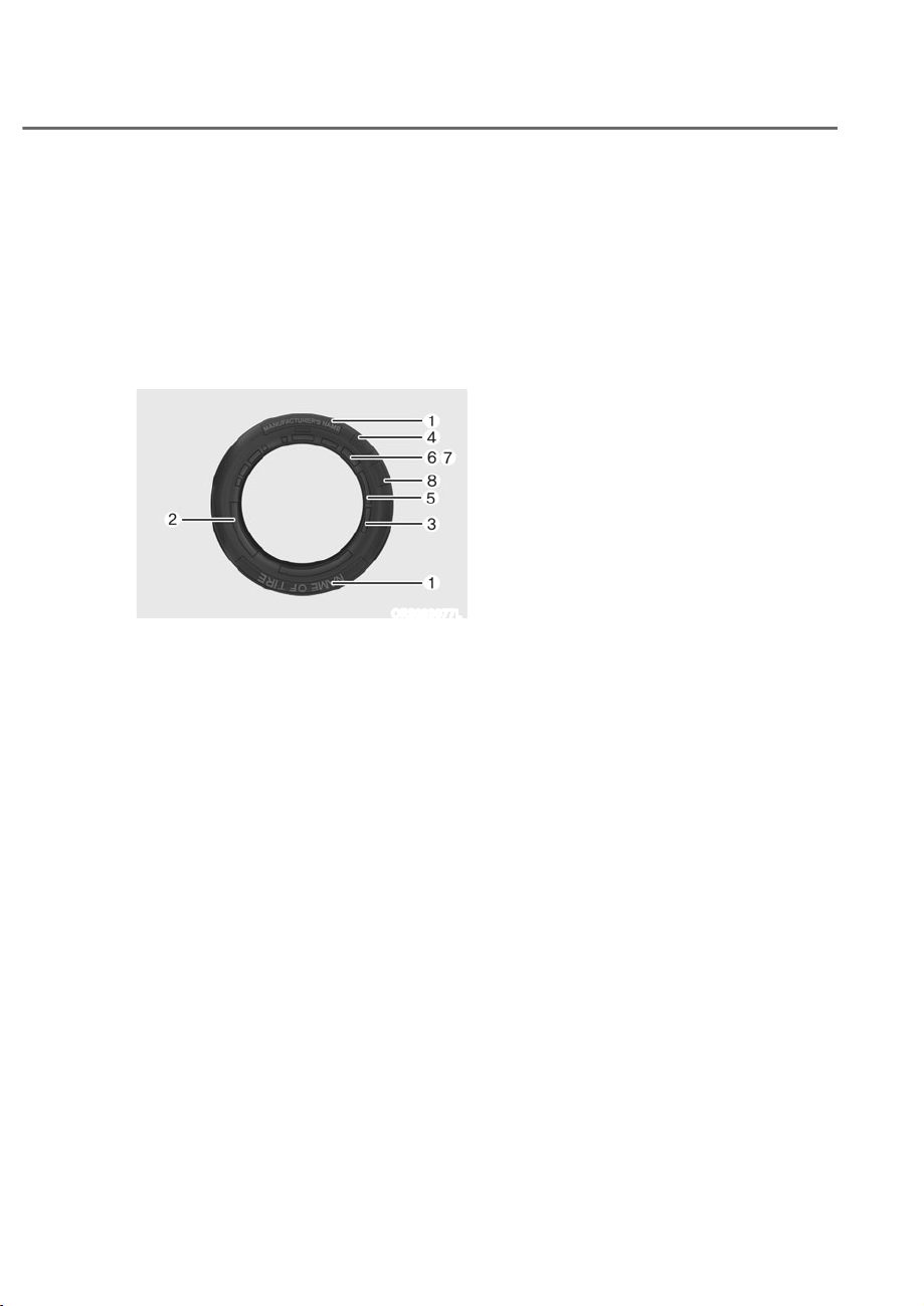
9-39
09
Tire Sidewall Labeling
This information identifies and
describes the fundamental
characteristics of the tire and also
provides the tire identification
number (TIN) for safety standard
certification. The TIN can be used to
identify the tire in case of a recall.
ORS093077L
1. Manufacturer or brand name
Manufacturer or brand name is
shown.
2. Tire size designation
A tire’s sidewall is marked with a
tire size designation. You will need
this information when selecting
replacement tires for your car.
The following explains what the
letters and numbers in the tire size
designation mean.
Example tire size designation:
(These numbers are provided as
an example only; your tire size
designator could vary depending on
your vehicle.)
245/45R20 103V
245 - Tire width in millimeters.
45 - Aspect ratio. The tire’s section
height as a percentage of its
width.
R - Tire construction code (Radial).
20 - Rim diameter in inches.
103 - Load Index, a numerical code
associated with the maximum
load the tire can carry.
V - Speed Rating Symbol. See
the speed rating chart in
this section for additional
information.
Wheel size designation
Wheels are also marked with
important information that you need
if you ever have to replace one. The
following explains what the letters
and numbers in the wheel size
designation mean.
Example wheel size designation:
8.5J X 20
8.5 - Rim width in inches.
J - Rim contour designation.
20 - Rim diameter in inches.

9-40
Maintenance
Tire speed ratings
The chart below lists many of the
different speed ratings currently
being used for passenger vehicle
tires. The speed rating is part of the
tire size designation on the sidewall
of the tire. This symbol corresponds
to that tire’s designed maximum safe
operating speed.
Speed Rating
Symbol
Maximum Speed
S 112 mph (180 km/h)
T 118 mph (190 km/h)
H 130 mph (210 km/h)
V 149 mph (240 km/h)
W 168 mph (270 km/h)
Y 186 mph (300 km/h)
3. Checking tire life (TIN : Tire
Identification Number)
Any tires that are over six years old,
based on the manufacturing date,
(including the spare tire) should be
replaced by new ones. You can find
the manufacturing date on the tire
sidewall (possibly on the inside of
the wheel), displaying the DOT Code.
The DOT Code is a series of numbers
on a tire consisting of numbers and
English letters. The manufacturing
date is designated by the last four
digits (characters) of the DOT code.
DOT : XXXX XXXX OOOO
The front part of the DOT shows a
plant code number, tire size and
tread pattern and the last four
numbers indicate week and year
manufactured.
For example:
DOT XXXX XXXX 1523 represents
that the tire was produced in the
15th week of 2023.
4. Genesis exclusive tire
Genesis Branded Vehicle
recommends that tires designed
specifically for Genesis vehicles
be used. You may find the marking
“GOE” (Genesis Original Equipment)
embossed on the tire sidewall.
5. Tire ply composition and material
The number of layers or plies of
rubber-coated fabric in the tire. Tire
manufacturers also must indicate the
materials in the tire, which include
steel, nylon, polyester, and others.
The letter “R” means radial ply
construction; the letter “D“ means
diagonal or bias ply construction;
and the letter “B” means belted-bias
ply construction.
6. Maximum permissible inflation
pressure
This number is the greatest amount
of air pressure that should be put in
the tire. Do not exceed the maximum
permissible inflation pressure. Refer
to the Tire and Loading Information
label for recommended inflation
pressure.
7. Maximum load rating
This number indicates the maximum
load in kilograms and pounds that
can be carried by the tire. When
replacing the tires on the vehicle,
always use a tire that has the same
load rating as the factory installed
tire.

9-41
09
8. Uniform tire quality grading
Quality grades can be found where
applicable on the tire sidewall
between tread shoulder and
maximum section width.
For example:
TREADWEAR 200
TRACTION AA
TEMPERATURE A
Tread wear
The tread wear grade is a
comparative rating based on the
wear rate of the tire when tested
under controlled conditions on a
specified government test course.
For example, a tire graded 150 would
wear one-and-a-half times (1½) as
well on the government course as a
tire graded 100.
The relative performance of tires
depends upon the actual conditions
of their use, however, and may
depart significantly from the norm
due to variations in driving habits,
service practices and differences in
road characteristics and climate.
These grades are molded on the
sidewalls of passenger vehicle tires.
The tires available as standard or
optional equipment on your vehicle
may vary with respect to grade.
Traction - AA, A, B
The traction grades, from highest
to lowest, are AA, A, B and C. Those
grades represent the tire’s ability to
stop on wet pavement as measured
under controlled conditions on
specified government test surfaces
of asphalt and concrete. A tire
marked C may have poor traction
performance.
WARNING
The traction grade assigned to
this tire is based on straight ahead
braking traction tests, and does not
include acceleration, cornering,
hydroplaning, or peak traction
characteristics.
Temperature - A, B
The temperature grades are A (the
highest), B and C representing the
tire’s resistance to the generation
of heat and its ability to dissipate
heat when tested under controlled
conditions on a specified indoor
laboratory test wheel.
Sustained high temperature can
cause the material of the tire to
degenerate and reduce tire life,
and excessive temperature can
lead to sudden tire failure. Grades
B and A represent higher levels of
performance on the laboratory test
wheel than the minimum required
by law.

9-42
Maintenance
WARNING
The temperature grade for this tire is
established for a tire that is properly
inflated and not overloaded.
Excessive speed, under-inflation,
over-inflation, or excessive loading,
either separately or in combination,
can cause heat build-up and
possible sudden tire failure. This
may cause loss of vehicle control
resulting in an accident.
Tire Terminology and Definitions
Air pressure
The amount of air inside the tire
pressing outward on the tire. Air
pressure is expressed in pounds per
square inch (psi) or kilopascal (kPa).
Accessory weight
This means the combined weight
of optional accessories. Some
examples of optional accessories
are automatic transmission, power
seats, and air conditioning.
Aspect ratio
The relationship of a tire’s height to
its width.
Belt
A rubber coated layer of cords that
is located between the plies and the
tread. Cords may be made from steel
or other reinforcing materials.
Bead
The tire bead contains steel wires
wrapped by steel cords that hold the
tire onto the rim.
Bias ply tire
A pneumatic tire in which the plies are
laid at alternate angles less than 90
degrees to the centerline of the tread.
Cold tire pressure
The amount of air pressure in a tire,
measured in pounds per square inch
(psi) or kilopascals (kPa) before a tire
has built up heat from driving.
Curb weight
This means the weight of a motor
vehicle with standard and optional
equipment including the maximum
capacity of fuel, oil and coolant, but
without passengers and cargo.
DOT markings
A code molded into the sidewall
of a tire signifying that the tire
is in compliance with the U.S.
Department of Transportation motor
vehicle safety standards. The DOT
code includes the Tire Identification
Number (TIN), an alphanumeric
designator which can also identify
the tire manufacturer, production
plant, brand and date of production.
GVWR
Gross Vehicle Weight Rating
GAWR FRT
Gross Axle Weight Rating for the
Front Axle.
GAWR RR
Gross Axle Weight Rating for the
Rear axle.

9-43
09
Intended outboard sidewall
The side of an asymmetrical tire,
that must always face outward when
mounted on a vehicle.
Kilopascal (kPa)
The metric unit for air pressure.
Light Truck (LT) tire
A tire designated by its manufacturer
as primarily intended for use on
lightweight trucks or multipurpose
passenger vehicles.
Load ratings
The maximum load that a tire is rated
to carry for a given inflation pressure.
Load index
An assigned number ranging from 1
to 279 that corresponds to the load
carrying capacity of a tire.
Maximum inflation pressure
The maximum air pressure to which
a cold tire may be inflated. The
maximum air pressure is molded
onto the sidewall.
Maximum load rating
The load rating for a tire at the
maximum permissible inflation
pressure for that tire.
Maximum loaded vehicle weight
The sum of curb weight; accessory
weight; vehicle capacity weight; and
production options weight.
Normal occupant weight
The number of occupants a vehicle
is designed to seat multiplied by 150
pounds (68 kg).
Occupant distribution
Designated seating positions.
Outward facing sidewall
An asymmetrical tire has a particular
side that faces outward when
mounted on a vehicle. The outward
facing sidewall bears white lettering
or bears manufacturer, brand, and/or
model name molding that is higher
or deeper than the same moldings
on the inner facing sidewall.
Passenger (P-Metric) tire
A tire used on passenger cars
and some light duty trucks and
multipurpose vehicles.
Ply
A layer of rubber-coated parallel
cords.

9-44
Maintenance
Pneumatic tire
A mechanical device made of rubber,
chemicals, fabric and steel or other
materials, that, when mounted on
an automotive wheel provides the
traction and contains the gas or fluid
that sustains the load.
Pneumatic options weight
The combined weight of installed
regular production options weighing
over 5 lb. (2.3 kg) in excess of the
standard items which they replace,
not previously considered in
curb weight or accessory weight,
including heavy duty breaks, ride
levelers, roof rack, heavy duty
battery, and special trim.
Recommended inflation pressure
Vehicle manufacturer’s
recommended tire inflation pressure
as shown on the tire placard.
Radial ply tire
A pneumatic tire in which the ply
cords that extend to the beads are
laid at 90 degrees to the centerline
of the tread.
Rim
A metal support for a tire and upon
which the tire beads are seated.
Sidewall
The portion of a tire between the
tread and the bead.
Speed rating
An alphanumeric code assigned to a
tire indicating the maximum speed
at which a tire can operate.
Traction
The friction between the tire and
the road surface. The amount of grip
provided.
Tread
The portion of a tire that comes into
contact with the road.
Treadwear indicators
Narrow bands, sometimes called
“wear bars”, that show across the
tread of a tire when only 1/16 inch of
tread remains.
UTQGS
Uniform Tire Quality Grading
Standards is a tire information
system that provides consumers
with ratings for a tire’s traction,
temperature and treadwear.
Ratings are determined by tire
manufacturers using government
testing procedures. The ratings are
molded into the sidewall of the tire.
Vehicle capacity weight
The number of designated seating
positions multiplied by 150 lbs. (68
kg) plus the rated cargo and luggage
load.
Vehicle maximum load on the tire
Load on an individual tire due to curb
and accessory weight plus maximum
occupant and cargo weight.
Vehicle normal load on the tire
Load on an individual tire that is
determined by distributing to each
axle its share of the curb weight,
accessory weight, and normal
occupant weight and dividing by 2.

9-45
09
Vehicle placard
A label permanently attached
to a vehicle showing the
original equipment tire size and
recommended inflation pressure.
All Season Tires
Genesis Branded Vehicle specifies
all season tires on some models to
provide good performance for use
all year round, including snowy and
icy road conditions. All season tires
are identified by ALL SEASON and/
or M+S (Mud and Snow) on the tire
sidewall. Snow tires have better
snow traction than all season tires
and may be more appropriate in
some areas.
Snow Tires
If you equip your car with snow
tires, they should be the same size
and have the same load capacity as
the original tires. Snow tires should
be installed on all four wheels;
otherwise, poor handling may result.
Snow tires should carry 4 psi (28 kPa)
more air pressure than the pressure
recommended for the standard
tires on the tire label on the driver’s
side of the center pillar, or up to the
maximum pressure shown on the tire
sidewall, whichever is less. Do not
drive faster than 75 mph (120 km/h)
when your vehicle is equipped with
snow tires.
Radial-Ply Tires
Radial-ply tires provide improved
tread life, road hazard resistance
and smoother high speed ride. The
radial-ply tires used on this vehicle
are of belted construction, and are
selected to complement the ride
and handling characteristics of
your vehicle. Radial-ply tires have
the same load carrying capacity,
as bias-ply or bias belted tires of
the same size, and use the same
recommended inflation pressure.
Mixing of radial-ply tires with
bias-ply or bias belted tires is not
recommended. Any combinations of
radial-ply and bias-ply or bias belted
tires when used on the same vehicle
will seriously deteriorate vehicle
handling. The best rule to follow
is: Identical pairs of radial-ply tires
should always be used as a set for
the front tires and a set for the rear
tires.
Longer wearing tires can be more
susceptible to irregular tread wear.
It is very important to follow the tire
rotation interval in this chapter to
achieve the tread life potential of
these tires. Cuts and punctures in
radial-ply tires are repairable only in
the tread area, because of sidewall
flexing. Consult your tire dealer for
radial-ply tire repairs.
WARNING
Do not mix bias ply and radial ply
tires under any circumstances.
This may cause unusual handling
characteristics that may cause loss
of vehicle control resulting in an
accident.

9-46
Maintenance
Low Aspect Ratio Tires (if
equipped)
The aspect ratio is lower than 50 on
low aspect ratio tires.
Because low aspect ratio tires are
optimized for handling and braking,
their sidewall is a little stiffer than
a standard tire. Also low aspect
ratio tires tend to be wider and
consequently have a greater contact
patch with the road surface. In some
instances they may generate more
road noise compared with standard
tires.
CAUTION
The side wall of a low aspect ratio
tire is shorter than the normal one.
Thus, the low-aspect wheel and
tire are easily damaged. Follow the
below instructions.
ȉ When driving on a rough road or
driving off a road, be careful not
to damage the tires and wheels.
After driving, inspect the tires
and wheels.
ȉ When passing over a pothole,
speed bump, manhole, or curb
stone, drive the vehicle slowly so
as not to damage the tires and
wheels.
ȉ When there is an impact on a tire,
inspect the tire condition. Or,
contact an authorized retailer of
Genesis Branded products.
ȉ Inspect the tire condition and
pressure every 1,800 miles (3,000
km) to prevent tire damage.
ȉ It is difficult to recognize a tire
damage only with your eyes.
When there is a slight hint of a
tire damage, check and replace
the tire to prevent the damage
caused by air leakage.
ȉ When a tire is damaged while
driving on a rough road, off a
road, or over obstacles, such as a
pothole, manhole, or curb stone,
your warranty does not cover the
damage.
ȉ The tire information is specified
on the tire side wall.
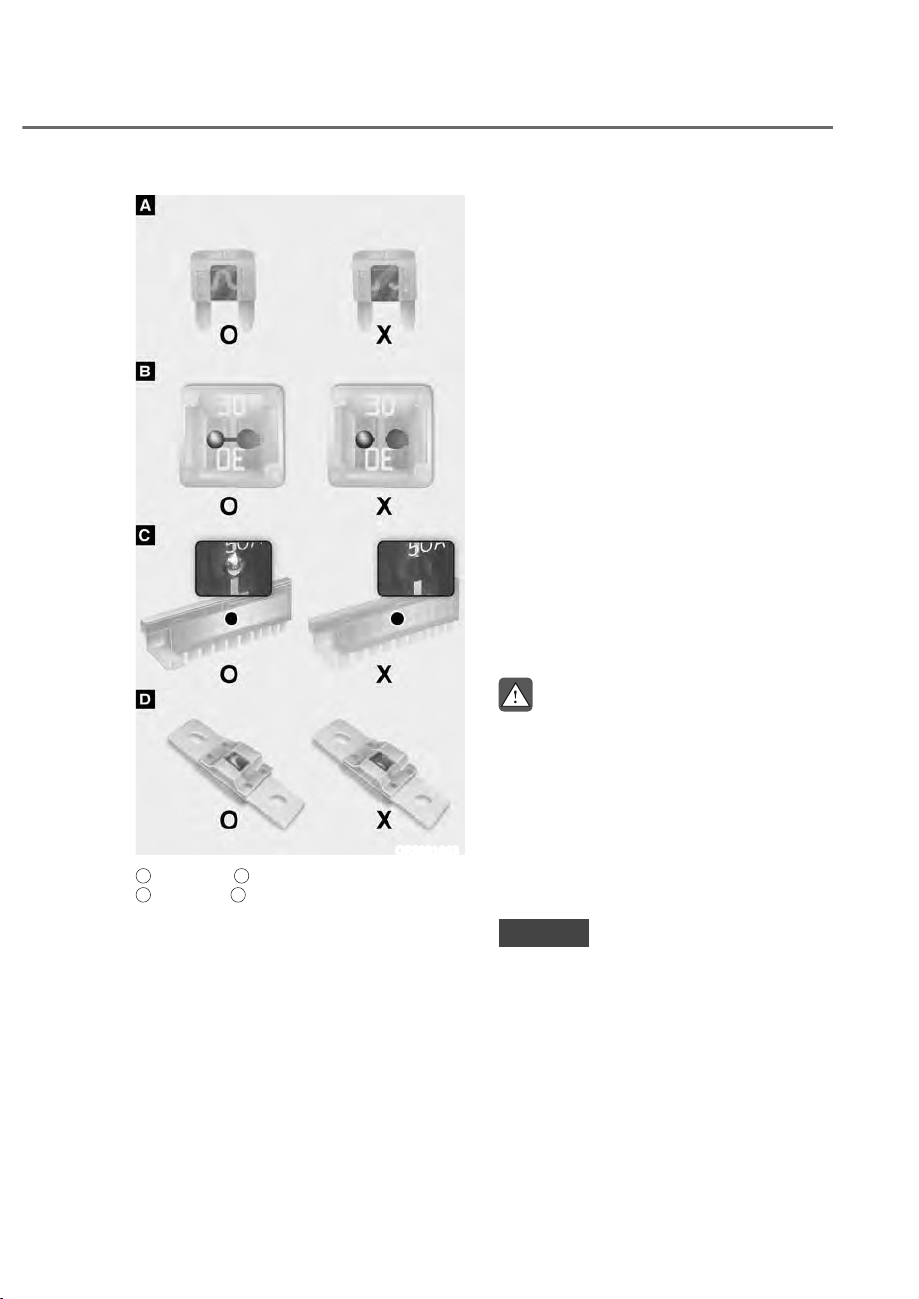
9-47
09
ORS091063
A
: Blade type,
B
: Cartridge type,
C
: Multi type,
D
: Midi type
O: Normal, X: Blown
A vehicle’s electrical system is protected
from electrical overload damage by
fuses.
This vehicle has 5 fuse panels, one
located in the driver’s side panel bolster,
the other in the engine compartment.
If any of your vehicle’s lights,
accessories, or controls do not work,
check the appropriate circuit fuse. If a
fuse has blown, the element inside the
fuse will be melted or broken.
If the electrical system does not work,
first check the driver’s side fuse panel.
Before replacing a blown fuse, turn the
engine and all switches off, and then
disconnect the negative battery cable.
Always replace a blown fuse with one of
the same rating.
If the replacement fuse blows, this
indicates an electrical problem.
Avoid using the system involved and
immediately consult an authorized
retailer of Genesis Branded products.
WARNING
NEVER replace a fuse with anything but
another fuse of the same rating.
ȉ A higher capacity fuse could cause
damage and possibly cause a fire.
ȉ Do not install a wire or aluminum
foil instead of the proper fuse -
even as a temporary repair. It may
cause extensive wiring damage and
possibly a fire.
NOTICE
Do not use a screwdriver or any other
metal object to remove fuses because
it may cause a short circuit and damage
the system.
FUSES
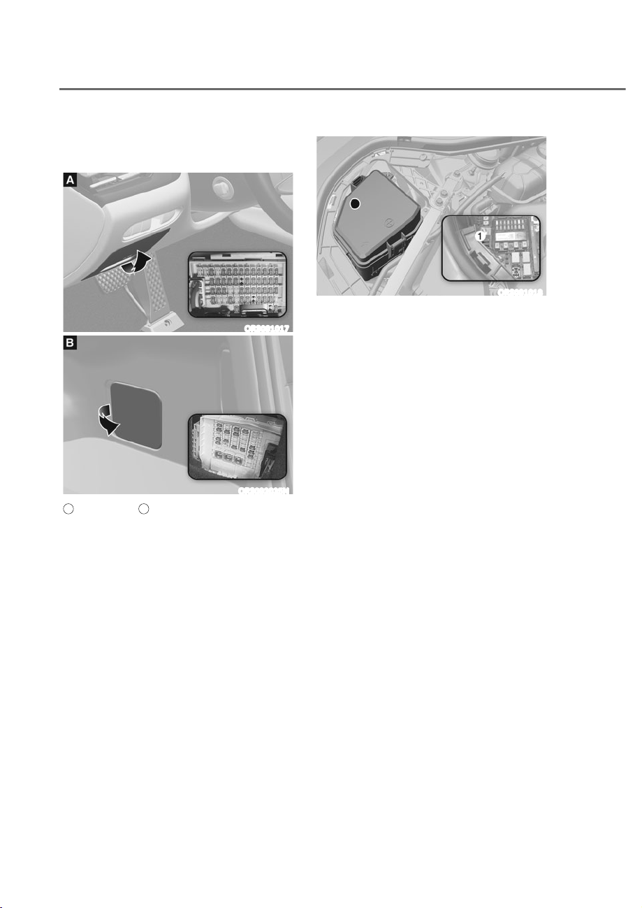
9-48
Maintenance
Instrument Panel Fuse
Replacement
ORS091017
ORS092035N
A
: Driver’s side,
B
: Trunk
1. Turn the vehicle off.
2. Turn all other switches off.
3. Open the fuse panel cover.
4. Refer to the label on the inside of
the fuse panel cover to locate the
suspected fuse location.
ORS091018
5. Pull the suspected fuse straight out.
Use the removal tool M provided in
the engine compartment fuses panel
cover.
6. Check the removed fuse; replace it if
it is blown. Spare fuses are provided in
the instrument panel fuse panels (or in
the engine compartment fuse panel).
7. Push in a new fuse of the same
rating, and make sure it fits tightly in
the clips. If it fits loosely, consult an
authorized retailer of Genesis Branded
products.
In an emergency, if you do not have
a spare fuse, use a fuse of the same
rating from a circuit you may not need
for operating the vehicle, such as the
cigarette lighter fuse.
If the headlights or other electrical
components do not work and the fuses
are undamaged, check the fuse panel
in the engine compartment. If a fuse is
blown, it must be replaced with the same
rating.
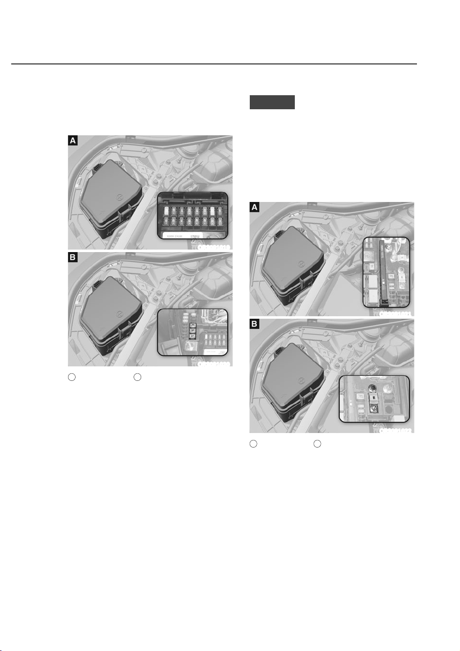
9-49
09
Engine Compartment Panel Fuse
Replacement
Blade fuse/Cartridge fuse
ORS091019
ORS091020
A
: Blade type fuse,
B
: Cartridge type fuse
1. Turn the vehicle off.
2. Turn all other switches off.
3. Remove the fuse panel cover by
pressing the tap and pulling up.
4. Check the removed fuse; replace it
if it is blown. To remove or insert the
fuse, use the fuse puller in the engine
compartment fuse panel.
5. Push in a new fuse of the same
rating, and make sure it fits tightly in
the clips. If it fits loosely, consult an
authorized retailer of Genesis Branded
products.
NOTICE
After checking the fuse panel in the
engine compartment, securely install
the fuse panel cover. You may hear a
clicking sound if the cover is securely
latched. If it is not securely latched,
electrical failure may occur from water
contact.
Multi fuse/Midi fuse
ORS091021
ORS091022
A
: Multi type fuse,
B
: Midi type fuse
If the multi fuse or midi fuse is blown,
consult an authorized retailer of Genesis
Branded products.
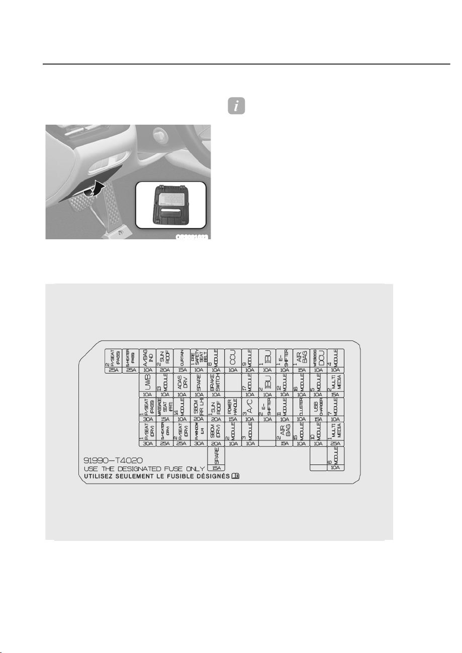
9-50
Maintenance
Fuse/Relay Panel Description
Instrument panel fuse panel
ORS091023
Inside the fuse/relay box cover, you can
find the fuse/relay label describing fuse/
relay names and ratings.
Information
Not all fuse panel descriptions in this
manual may be applicable to your vehicle
the information is accurate at the time of
printing. When you inspect the fuse box on
your vehicle, refer to the fuse box label.
ORS092024N

9-51
09
Instrument panel fuse panel
Fuse Name
Fuse
Rating
Circuit Protected
P/SEAT (PASS)2
25A Passenger Power Seat Module
S/HEATER
(PASS)
25A Passenger Power Seat Module
A/BAG IND
10A Overhead Console
UWB
10A
BLE Unit, Interior UBW Unit #1/#2/#3, Interior UBW Unit,
Rear UBW Unit LH/RH, Front UBW Unit LH/RH
P/SEAT (PASS)1
30A Passenger Power Seat Module
P/SEAT (DRV)1
30A Driver Power Seat Module
SUNROOF2
20A Sunroof Rear Rollo Controller
MODULE13
10A
Electro Chromic Mirror, Data Link Connector, Front A/C
Controller, A/C Control Module, AMP CCIC Keyboard,
Smart Phone Wireless Charger, Support AMP, LDC (IG1
Input), CCIC Head Unit, REAR Junction Block (LDC - IG1
Input), Driver/Passenger Power Seat Module, Rear Seat
CCS Module LH/RH, Rear Seat Heater Control Module LH/
RH, Rear Power Seat Module LH/RH, Rear Seat Console
Wireless Charger, Rear Seat Console UVC Lamp, Armrest
Touch Screen, AMP
MASSAGE SEAT
(FRT)
15A
Driver/Passenger Lumbar Support Unit, Passenger Foot
Massage Unit
S/HEATER
(DRV)
25A Driver Power Seat Module
CURTAIN
15A IBU
ADAS DRV1
10A ADAS Unit (Driving)
MODULE14
10A
Driver/Passenger Door Outside Handle, Rear Door Outside
Handle LH/RH
P/SEAT (DRV)2
25A Driver Power Seat Module
PRESAFETY
SEAT BELT1
10A Pre-Active Seat Belt Unit
SBCM (RR LH)
20A Rear SBCM LH
P/WINDOW
(LH)
30A
Driver Safety Power Window Module, Rear Safety Power
Window Module LH
MODULE8
10A
ADAS Unit (Parking), Center Control Panel, CCIC Head Unit,
Rear Seat Console Tray Lamp, Rear Seat Console Remote
Control Switch, Instrument Cluster, Rear Seat Console UVC
Lamp
BRAKE SWITCH
10A IBU, Stop Lamp Switch
SUNROOF1
20A Sunroof Glass Controller

9-52
Maintenance
Fuse Name
Fuse
Rating
Circuit Protected
SBCM (DRV)
20A Driver SBCM
CCU1
10A CCU
POWER
HANDLE
15A Steering Tilt & Telescopic Unit
MODULE2
10A
Front A/C Controller, Multifunction Switch, Head Lamp LH/
RH
MODULE9
10A
Multifunction Switch, Data Link Connector, CCIC Keyboard,
Rain Sensor, Driver Power Window Switch, Driver Power
Outside Mirror Switch
CCU2
10A Stop Lamp Switch, CCU
A/C3
10A
A/C Control Module, Front A/C Controller, Incar
Temperature Sensor, E/R Sub Junction Block (PTC Heater
#1/#2 Relay) Rear Junction Block (Rear Blower Relay)
MODULE3
10A IBU, IAU
IBU1
10A IBU, IAU
IBU2
10A IBU, BMS Control Module
E-SHIFTER2
10A Electronic ATM Shift Lever Dial
E-SHIFTER1
10A Electronic ATM Shift Lever Dial
MODULE12
10A
Rear Corner Radar LH/RH, ECS Unit, Air ECS Unit, AWD
ECU, RWS Module, ADAS Unit (Parking), IBU, Crash Pad
Switch, Steering Tilt & Telescopic Unit, Front View Camera
(ADAS)
MODULE11
10A Driver Power Window Switch, Multifunction Switch, IAU
AIR BAG2
15A SRS Control Module, Passenger Occupant Detection Sensor
AIR BAG1
15A SRS Control Module
MODULE16
10A
Front Console Mood Lamp #1/2, Garnish Lamp LH/RH,
Mood Lamp Unit, Roof Mood Lamp #1/2, Driver/Passenger
Door Garnish Mood Lamp, Rear Door Garnish Mood Lamp
LH/RH, ADAS Unit (Parking)
CLUSTER
10A Instrument Cluster, Head-Up Display
MODULE15
10A ADAS Unit (Driving)
Wireless DCU
10A Domain Control Unit
MODULE5
10A
Rear Door Curtain, Rear Occupant Alert (ROA) Sensor,
Clock Spring, Front Console Switch, Active Air Flap Module,
Steering Tilt & Telescopic Unit

9-53
09
Fuse Name
Fuse
Rating
Circuit Protected
USB CHARGER
15A Rear USB Charger Connector
MODULE10
10A
IAU, CCU, IBU, Electronic ATM Shift Lever Dial, LDC (ACC
Input), Armrest Console Lamp, Domain Control Unit, Rear
Junction Block (LDC - ACC Input), E/R Sub Junction Block
(Power Outlet Relay)
MODULE4
10A
Security Indicator, A/C Control Module, Head-Up Display,
Front A/C Controller
MULTIMEDIA2
15A
Center Control Panel, Rear Seat Console Multimedia Jack,
Rear Seat Console Remote Control Switch
MODULE7
10A
Smart Phone Wireless Charger, Rear Seat Console Wireless
Charger, Front Corner Radar LH/RH, Rear Corner Radar LH/
RH
MULTIMEDIA1
25A CCIC Head Unit
MODULE6
10A
Armrest Touch Screen, Instrument Cluster, Front A/C
Controller, Head-Up Display
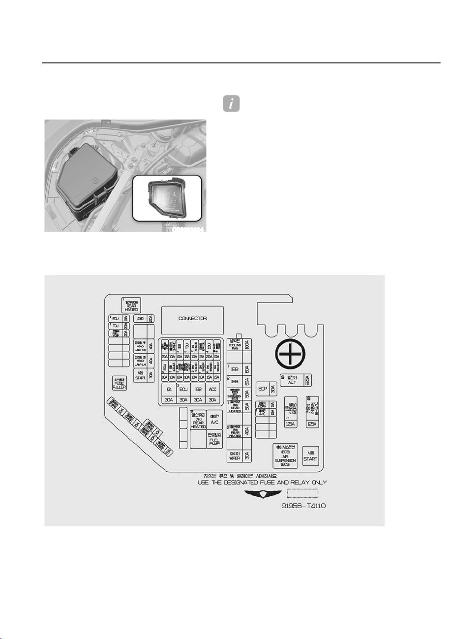
9-54
Maintenance
Engine compartment fuse panel
(Engine room junction block)
ORS091034
Inside the fuse/relay box cover, you can
find the fuse/relay label describing fuse/
relay names and ratings.
Information
Not all fuse panel descriptions in this
manual may be applicable to your vehicle
the information is accurate at the time of
printing. When you inspect the fuse panel
in your vehicle, refer to the fuse panel
label.
ORS092059N

9-55
09
Engine compartment fuse panel
Type Fuse Name
Fuse
Rating
Circuit Protected
MAIN
ALT
225A Alternator
MDPS1
125A MDPS Unit
e-S/C
125A
[Mild HEV] Electric Super Charging Unit
(Power)
MULTI
COOLING FAN
100A Colling Fan Motor
IEB1
60A IEB Unit
IEB2
60A IEB Unit
AIR SUSPENSION
(ECS)
50A Air Suspension (ECS) Relay
REAR HEATED1
50A Rear Heated #1 Relay
REAR HEATED2
40A Rear Heated #2 Relay
WIPER
30A Wiper Motor
SB
EOP
30A Electronic Oil Pump
HEAD LAMP RH
40A Head Lamp RH
HEAD LAMP LH
40A Head Lamp LH
START
30A Start Relay
MICRO
HORN
15A PCB Block (Horn Relay)
A/C1
15A A/C Relay
ECU1
15A ECM
TCU1
20A TCM
FUEL PUMP
20A Fuel Pump Relay
4WD
20A AWD ECU

9-56
Maintenance
Engine compartment fuse panel
Fuse Name
Fuse
Rating
Circuit Protected
IG1
30A IG1 Relay
ECU3
30A Engine Control Relay
IG2
30A IG2 Relay
ACC
30A ACC Relay
ECU2
10A ECM
EWP
20A Electronic Water Pump
MODULE1
10A Front Radar, Front Corner Radar LH/RH
MDPS2
10A MDPS Unit
IEB3
10A IEB Unit
TCU2
15A TCM, P/N Relay, Electronic Oil Pump
SENSOR3
10A Oxygen Sensor #1 (B1/S1), Oxygen Sensor #2 (B2/S1)
SENSOR2
10A
Oxygen Sensor #3 (B1/S2), Oxygen Sensor #4 (B2/S2),
Purge Control Solenoid Valve, Oil Pump Solenoid Valve,
Canister Close Valve, Oil Control Valve (Intake #1/#2), Oil
Control Valve (Exhaust #1/#2), RCV Control Solenoid Valve
#1/#2, E/R Junction Block (A/C Relay)
SENSOR1
10A
E/R Junction Block (Fuel Pump Relay), Injector
#1/#2/#3/#4/#5/#6 (MPI)
IGN COIL
15A Ignition Coil #1/#2/#3/#4/#5/#6
SENSOR4
15A Cooling Fan Motor, Electric Super Charging Unit (Signal)
ECU4
20A ECM
WASHER
15A WASHER RELAY
MHSG
10A
[With Mild HEV] Mild Hybrid Starter & Generator Motor
(Signal)
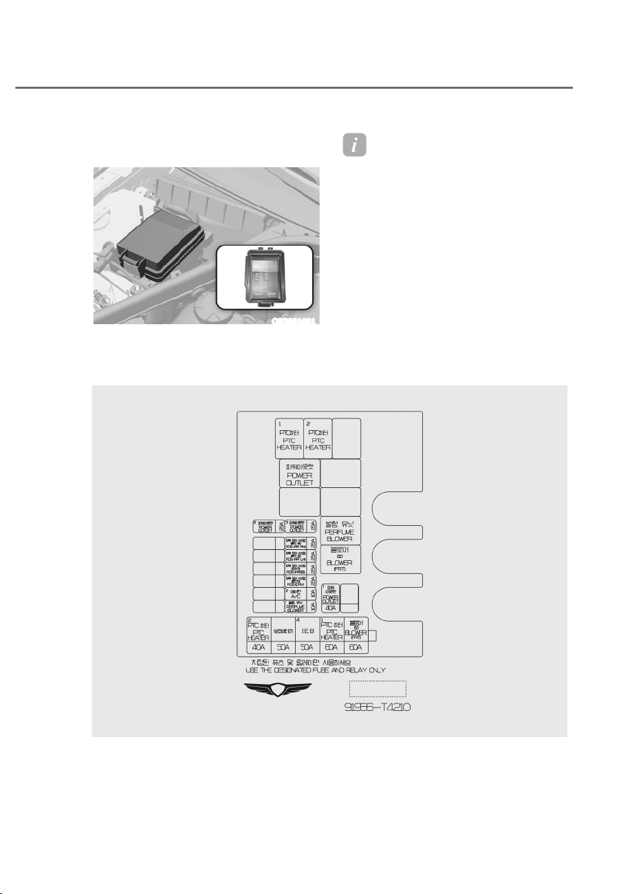
9-57
09
Engine compartment fuse panel
(Engine room junction block)
ORS091051
Inside the fuse/relay box cover, you can
find the fuse/relay label describing fuse/
relay names and ratings.
Information
Not all fuse panel descriptions in this
manual may be applicable to your vehicle
the information is accurate at the time of
printing. When you inspect the fuse panel
in your vehicle, refer to the fuse panel
label.
ORS091060

9-58
Maintenance
Engine compartment fuse panel
Type Fuse Name
Fuse
Rating
Circuit Protected
MULTI
BLOWER (FRT)
60A Blower (FRT) Relay
PTC HEATER1
60A PTC Heater #1 Relay
IEB4
50A IEB Unit
PTC HEATER2
40A PTC Heater #2 Relay
SB
POWER
OUTLET1
40A Power Outlet Relay
MICRO
POWER
OUTLET2
25A Front Power Outlet
POWER
OUTLET3
25A
Rear Power Outlet, Rear Seat Console Power
Outlet
PDS (RR RH)
25A Rear Power Door Closing Actuator RH
PDS (RR LH)
25A Rear Power Door Closing Actuator LH
PDS (PASS)
25A Passenger Power Door Closing Actuator
PDS (DRV)
25A Driver Power Door Closing Actuator
A/C2
10A Blower (FRT) Relay, Perfume Blower Relay
PERFUME
BLOWER
10A Perfume Blower Relay
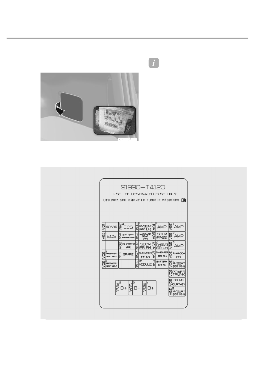
9-59
09
Trunk fuse panel (Rear sub junction
block)
ORS091035
Inside the fuse/relay box cover, you can
find the fuse/relay label describing fuse/
relay names and ratings.
Information
Not all fuse panel descriptions in this
manual may be applicable to your vehicle
the information is accurate at the time of
printing. When you inspect the fuse panel
in your vehicle, refer to the fuse panel
label.
ORS092029N

9-60
Maintenance
Rear unction block
Fuse Name
Fuse
Rating
Circuit Protected
B+2 50A
ICU Junction Block (IPS4, IPS5, Fuse - E-SHIFTER1, BRAKE
SWITCH, IBU1, UWB, MODULE9, CCU1, AIR BAG1)
B+3 50A ICU Junction Block (IPS1/IPS6/IPS7/IPS8)
B+1 50A
ICU Junction Block (LDC, Long Term Load Latch Relay,
Short Term Load Latch Relay)
ECS1 15A ECS Unit, Air ECS Unit
PRESAFETY SEAT
BELT2
30A Pre-Active Seat Belt Unit
PRESAFETY SEAT
BELT3
30A Pre-Active Seat Belt Unit
ECS2 25A Air ECS Unit
BATTERY
MANAGEMENT
15A BMS Control Module
BLOWER (RR) 20A Rear Blower Relay
P/SEAT (RR LH)1 30A Rear Power Seat Module LH
MASSAGE SEAT
(RR)
15A Rear Seat Lumbar Support Unit LH/RH
SBCM (RR RH) 20A Rear SBCM RH
S/HEATER
(RR LH)
25A
Rear Power Seat Module LH, Rear Seat CCS Module LH,
Rear Seat Heater Control Module LH
MODULE18 10A
Driver/Passenger Power Seat Switch, Driver/Passenger
Power Seat Module, Driver/Passenger Lumbar Support
Unit, Passenger Foot Massage Unit, Rear Seat Console
Switch LH/RH, Rear Power Seat Module LH/RH, Rear Seat
Lumbar Support Unit LH/RH, PTL Unit
AMP4 10A AMP, Support AMP
SBCM (PASS) 20A Passenger SBCM
P/SEAT (RR LH)2 25A Rear Power Seat Module LH
S/HEATER
(RR RH)
25A
Rear Power Seat Module RH, Rear Seat CCS Module RH,
Rear Seat Heater Control Module RH
BATTERY C/FAN 15A BMS Cooling Fan
AMP1 25A AMP
AMP2 25A AMP
AMP3 25A Support AMP
P/WINDOW (RH) 30A
Passenger Safety Power Window Module, Rear Safety
Power Window Module LH
P/SEAT (RR RH)1 30A Rear Power Seat Module RH
POWER TRUNK 30A PTL Unit
RR DR CURTAIN 20A Rear Door Curtain
P/SEAT (RR RH)2 25A Rear Power Seat Module RH
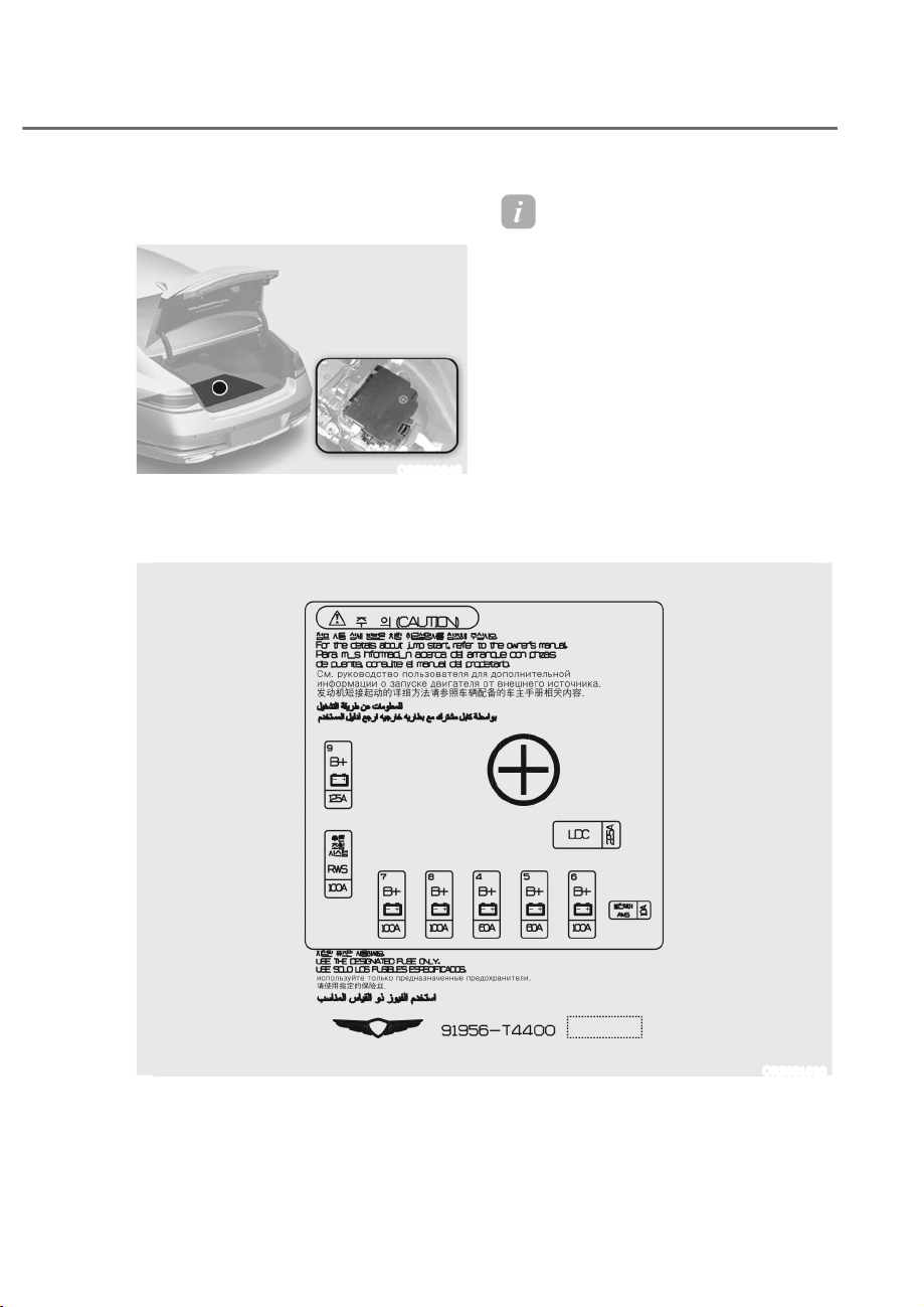
9-61
09
Trunk fuse panel (Battery junction
block)
ORS091048
Inside the fuse/relay box cover, you can
find the fuse/relay label describing fuse/
relay names and ratings.
Information
Not all fuse panel descriptions in this
manual may be applicable to your vehicle
the information is accurate at the time of
printing. When you inspect the fuse panel
in your vehicle, refer to the fuse panel
label.
ORS091030

9-62
Maintenance
Battery unction block
Fuse Name Fuse Rating Circuit Protected
LDC
225A
[Mild HEV] Battery System Assembly (Low DC-DC
Converter)
AMS
10A 12V Battery Sensor
B+6
100A
Rear Junction Block (Fuse - P/WINDOW (RH), BATTERY C/
FAN, P/SEAT (RR RH)1, P/SEAT (RR RH)2, S/HEATER (RR
RH), POWER TRUNK, RR DR CURTAIN, B+1)
B+5
60A
ICU Junction Block (Fuse - P/SEAT (PASS)1, P/SEAT
(PASS)2, MASSAGE SEAT (FRT), ADAS DRV1, S/HEATER
(PASS), CURTAIN, SUNROOF2, MODULE14)
B+4
60A
ICU Junction Block (Fuse - SBCM (DRV), SBCM (RR LH),
SUNROOF1, P/SEAT (DRV)1, P/SEAT (DRV)2, POWER
HANDLE, S/HEATER (DRV), P/WINDOW (LH))
B+8
100A
Rear Junction Block (LDC, Fuse - PRESAFETY SEAT
BELT2, ECS1, ECS2, PRESAFETY SEAT BELT3, BATTERY
MANAGEMENT)
B+7
100A
Rear Junction Block (Fuse -SBCM (PASS), SBCM (RR RH),
P/SEAT (RR LH)1, P/SEAT (RR LH)2, S/HEATER (RR LH),
MASSAGE SEAT (RR), BLOWER (RR), MODULE18, B+2, B+3)
RWS
100A RWS Module
B+9
125A
E/R Junction Block (Fuse - HEAD LAMP LH, START, TCU1,
4WD, HEAD LAMP RH, ECU1, FUEL PUMP, ECU3)

9-63
09
Consult an authorized retailer of
Genesis Branded products to replace
most vehicle light bulbs. It is difficult
to replace vehicle light bulbs because
other parts of the vehicle must be
removed before you can get to the bulb.
This is especially true for removing the
headlight assembly to get to the bulb(s).
Removing/installing the headlight
assembly can result in damage to the
vehicle.
WARNING
ȉ Prior to working on a light, depress
the foot brake, shift to P (Park), apply
the parking brake, press the Engine
Start/Stop button to the OFF position
and take the smart key with you
when leaving the vehicle to avoid
sudden movement of the vehicle and
to prevent possible electric shock.
ȉ Be aware the bulbs may be hot and
may burn your fingers.
NOTICE
Be sure to replace the burned-out bulb
with one of the same wattage rating.
Otherwise, it may cause damage to the
fuse or electrical wiring system.
NOTICE
To prevent damage, do not clean the
headlight lens with chemical solvents
or strong detergents.
Information
The headlight and tail lamp lenses could
appear frosty if the vehicle is washed after
driving or the vehicle is driven at night in
wet weather. This condition is caused by
temperature difference between the lamp
inside and outside and, it does not indicate
a problem with your vehicle. When
moisture condenses in the lamp, it will be
removed after driving with the headlight
on. The removable level may differ
depending on lamp size, lamp position
and environmental condition. However, if
moisture is not removed, have the vehicle
inspected by an authorized retailer of
Genesis Branded products.
Information
ȉ A normally functioning lamp may
flicker momentarily to stabilize the
vehicle’s electrical control system.
However, if the lamp goes out after
flickering momentarily, or continues to
flicker, have the system checked by an
authorized retailer of Genesis Branded
products.
ȉ The parking lamp may not turn on
when the parking lamp switch is turned
on, but the parking lamp and headlight
switch may turn on when the headlight
switch is turned on. This may be caused
by network failure or vehicle electrical
control system malfunction. If this
occurs, have the system checked by an
authorized retailer of Genesis Branded
products.
Information
The headlight aiming should be ad usted
after an accident or after the headlight
assembly is reinstalled at an authorized
retailer of Genesis Branded products.
LIGHT BULBS
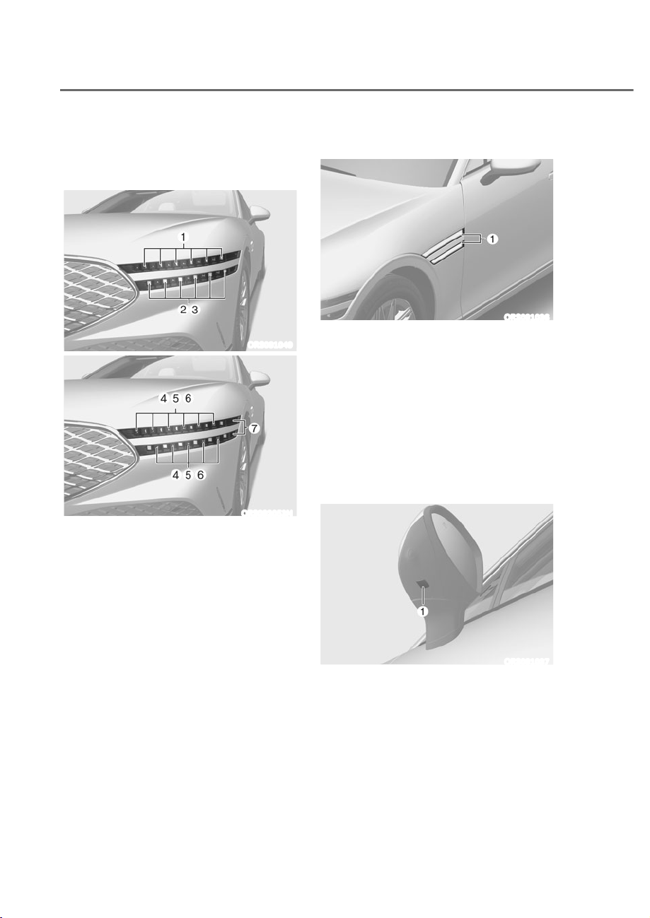
9-64
Maintenance
Headlight, Parking Lamp, Turn
Signal Lamp, Daytime Running
Light (DRL) Replacement
ORS091049
ORS092053N
M Headlight (Low)
N Headlight (High)
O Headlight (Low beam assist)
P Daytime running light
Q Parking lamp
R Turn signal lamp
S Side marker lamp
If the LED lamp does not operate, have
the system inspected by an authorized
retailer of Genesis Branded products.
The LED lamps cannot be replaced as
a single unit because it is an integrated
unit. The LED lamps has to be replaced
with the unit.
A skilled technician should check or
repair the LED lamp, for it may damage
related parts of the vehicle.
Side Repeater Lamp Replacement
ORS091036
If the LED lamp M does not operate, have
the system inspected by an authorized
retailer of Genesis Branded products.
The LED lamps cannot be replaced as
a single unit because it is an integrated
unit. The LED lamps has to be replaced
with the unit.
A skilled technician should check or
repair the LED lamp, for it may damage
related parts of the vehicle.
Puddle Lamp Replacement
ORS091037
If the LED lamp M does not operate, have
the system inspected by an authorized
retailer of Genesis Branded products.
The LED lamps cannot be replaced as
a single unit because it is an integrated
unit. The LED lamps has to be replaced
with the unit.
A skilled technician should check or
repair the LED lamp, for it may damage
related parts of the vehicle.
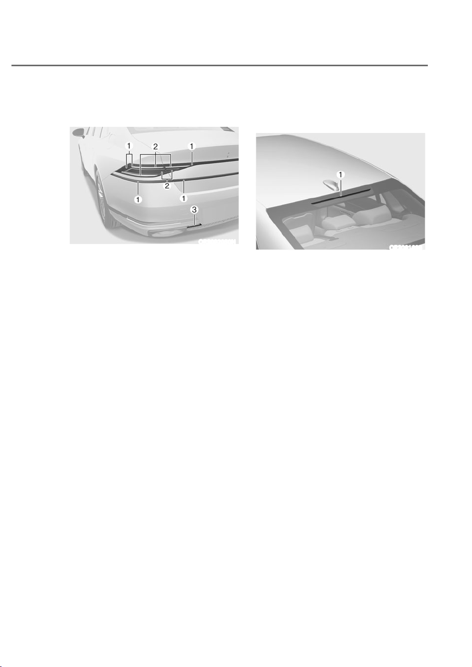
9-65
09
Rear Combination Lamp
Replacement
ORS092050N
M Tail lamp/Side marker lamp
N Stop lamp/Turn signal lamp
O Reverse lamp
If the LED lamp does not operate, have
the system inspected by an authorized
retailer of Genesis Branded products.
The LED lamps cannot be replaced as
a single unit because it is an integrated
unit. The LED lamps has to be replaced
with the unit.
A skilled technician should check or
repair the LED lamp, for it may damage
related parts of the vehicle.
High Mounted Stop Lamp
Replacement
ORS091038
If the LED lamp M does not operate, have
the system inspected by an authorized
retailer of Genesis Branded products.
The LED lamps cannot be replaced as
a single unit because it is an integrated
unit. The LED lamps has to be replaced
with the unit.
A skilled technician should check or
repair the LED lamp, for it may damage
related parts of the vehicle.

9-66
Maintenance
License Plate Lamp Replacement
ORS091039
If the LED lamp M does not operate, have
the system inspected by an authorized
retailer of Genesis Branded products.
The LED lamps cannot be replaced as
a single unit because it is an integrated
unit. The LED lamps has to be replaced
with the unit.
A skilled technician should check or
repair the LED lamp, for it may damage
related parts of the vehicle.
Interior light replacement
ORS091070L
ORS091041
ORS091042
A
: Front lamp,
B
: Rear lamps (without sunroof),
C
: Rear lamps (with sunroof)
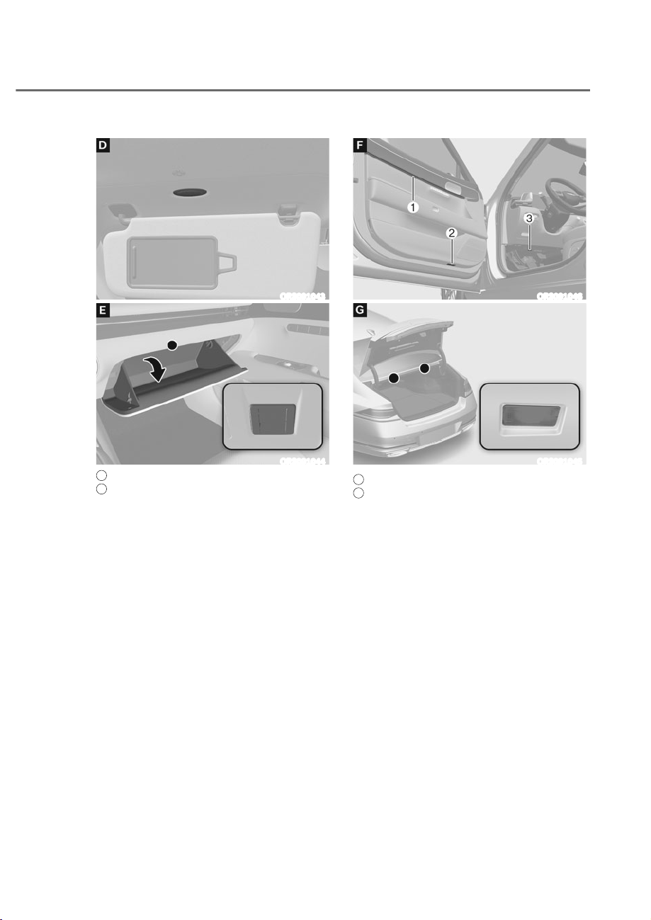
9-67
09
ORS091043
ORS091044
D
: Vanity mirror lamp,
E
: Glove box lamp
If the LED lamp does not operate, have
the system inspected by an authorized
retailer of Genesis Branded products.The
LED lamps cannot be replaced as a single
unit because it is an integrated unit. The
LED lamps has to be replaced with the
unit. A skilled technician should check or
repair the LED lamp, for it may damage
related parts of the vehicle.
ORS091046
ORS091045
F
:
M
Mood lamp,
N
Door foot lamp,
O
Foot lamp,
G
: Trunk lamp
If the LED lamp does not operate, have
the system inspected by an authorized
retailer of Genesis Branded products.
The LED lamps cannot be replaced as
a single unit because it is an integrated
unit. The LED lamps has to be replaced
with the unit.
A skilled technician should check or
repair the LED lamp, for it may damage
related parts of the vehicle.

9-68
Maintenance
Exterior Care
NOTICE
If you park your vehicle near a stainless
steel sign or glass facade building, the
vehicle’s exterior plastic parts such
as a bumper, spoiler, garnish, lamp
or outside rearview mirror might be
damaged due to sunlight reflected from
the sign or building. To prevent damage
of the exterior plastic parts, you should
avoid parking in areas where light may
be reflected or use a car cover. (The
exterior plastic parts applied to your
vehicle may vary.)
Exterior general caution
It is very important to follow the label
directions when using any chemical
cleaner or polish. Read all warning and
caution statements that appear on the
label.
Finish maintenance
Washing
To help protect your vehicle’s finish from
rust and deterioration, wash it thoroughly
and frequently at least once a month
with lukewarm or cold water.
If you use your vehicle for off-road
driving, you should wash it after each
off-road trip. Pay special attention to the
removal of any accumulation of salt, dirt,
mud, and other foreign materials. Make
sure the drain holes in the lower edges
of the doors and rocker panels are kept
clear and clean.
Insects, tar, tree sap, bird droppings,
industrial pollution and similar deposits
can damage your vehicle’s finish if not
removed immediately.
Even prompt washing with plain water
may not completely remove all these
deposits. A mild soap, safe for use on
painted surfaces, should be used.
After washing, rinse the vehicle
thoroughly with lukewarm or cold water.
Do not allow soap to dry on the finish.
APPEARANCE CARE
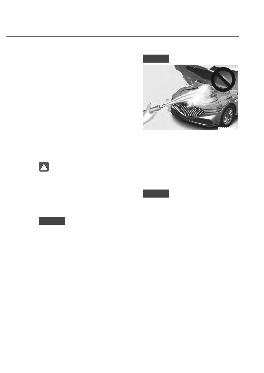
9-69
09
High-pressure washing
ȉ When using high-pressure washers,
make sure to maintain sufficient
distance from the vehicle.
Insufficient clearance or excessive
pressure can lead to component
damage or water penetration.
ȉ Do not spray the camera, sensors or
its surrounding area directly with a
high pressure washer. Shock applied
from high pressure water may cause
the device to not operate normally.
ȉ Do not bring the nozzle tip close to
boots (rubber or plastic covers) or
connectors as they may be damaged
if they come into contact with high
pressure water.
WARNING
After washing the vehicle, test the
brakes while driving slowly to see
if they have been affected by water
before getting on the road. If braking
performance is impaired, dry the
brakes by applying them lightly while
maintaining a slow forward speed.
NOTICE
ȉ Do not use strong soap, chemical
detergents or hot water, and do not
wash the vehicle in direct sunlight
or when the body of the vehicle is
warm.
ȉ Be careful when washing the side
windows of your vehicle.
ȉ Especially, with high-pressure water,
water may leak through the windows
and wet the interior.
ȉ To prevent damage to the plastic
parts, do not clean with chemical
solvents or strong detergents.
NOTICE
ORS091047
ȉ Water washing in the engine
compartment including high
pressure water washing may cause
the failure of electrical circuits
located in the engine compartment.
ȉ Never allow water or other liquids
to come in contact with electrical/
electronic components inside the
vehicle as this may damage them.
NOTICE
Matte paint finish vehicle (if equipped)
Automatic car wash which uses rotating
brushes should not be used as this can
damage the surface of your vehicle. A
steam cleaner which washes the vehicle
surface at high temperature may cause
the oil to adhere and leave stains that is
difficult to remove.
Use a soft cloth (for example, microfiber
towel or sponge) when washing your
vehicle and dry with a microfiber towel.
When you hand wash your vehicle, you
should not use a cleaner that finishes
with wax.

9-70
Maintenance
Waxing
A good coat of wax is a barrier between
your paint and contamination. Keeping
a good coat of wax on your vehicle will
help protect it.
Wax the vehicle until water will no longer
bead on the paint.
Always wash and dry the vehicle before
waxing. Use a good quality liquid or
paste wax, and follow the manufacturer’s
instructions. Wax all metal trim to protect
it and to maintain its luster.
Removing oil, tar, and similar materials
with a spot remover will usually strip the
wax from the finish. Be sure to re-wax
these areas even if the rest of the vehicle
does not yet need waxing.
NOTICE
ȉ Wiping dust or dirt off the body with
a dry cloth will scratch the finish.
ȉ Do not use steel wool, abrasive
cleaners, or strong detergents
containing highly alkaline or
caustic agents on chrome-plated or
anodized aluminum parts. This may
result in damage to the protective
coating and cause discoloration or
paint deterioration.
NOTICE
Matte paint finish vehicle (if equipped)
Do not use any polish protector such
as a detergent, an abrasive or a polish.
In case wax is applied, remove the wax
immediately using a silicon remover
and if any tar or tar contaminant is on
the surface use a tar remover to clean.
However, be careful not to apply too
much pressure on the painted area.
Finish damage repair
Deep scratches or stone chips in the
painted surface must be repaired
promptly. Exposed metal will quickly
rust and may develop into a major repair
expense.
NOTICE
If your vehicle is damaged and requires
any metal repair or replacement,
be sure the body shop applies anti-
corrosion materials to the parts
repaired or replaced.
NOTICE
Matte paint finish vehicle (if equipped)
In case of matte paint finish vehicles,
it is impossible to modify only the
damaged area and repair of the whole
part is necessary. If the vehicle is
damaged and painting is required, have
your vehicle maintained and repaired
by an authorized retailer of Genesis
Branded products. Take extreme care,
as it is difficult to restore the quality
after the repair.

9-71
09
Bright-metal maintenance
ȉ To remove road tar and insects, use
a tar remover, not a scraper or other
sharp object.
ȉ To protect the surfaces of brightmetal
parts from corrosion, apply a coating
of wax or chrome preservative and rub
to a high luster.
ȉ During winter weather or in coastal
areas, cover the bright metal parts
with a heavier coating of wax or
preservative. If necessary, coat the
parts with non-corrosive petroleum
jelly or other protective compound.
Underbody maintenance
Corrosive materials used for ice and
snow removal and dust control may
collect on the underbody. If these
materials are not removed, accelerated
rusting can occur on underbody parts
such as the fuel lines, frame, floor pan
and exhaust system, even though they
have been treated with rust protection.
Thoroughly flush the vehicle underbody
and wheel openings with lukewarm or
cold water once a month, after off-road
driving and at the end of each winter.
Pay special attention to these areas
because it will do more harm than good
if the road grime becomes wet without
removing it. The lower edges of doors,
rocker panels, and frame members have
drain holes that should not be allowed
to clog with dirt; trapped water in these
areas can cause rusting.
WARNING
After washing the vehicle, test the
brakes while driving slowly to see if
they have been affected by water. If
braking performance is impaired, dry
the brakes by applying them lightly
while maintaining a slow forward
speed.
Aluminum wheel maintenance
The aluminum wheels are coated with a
clear protective finish.
ȉ Do not use abrasive cleaner, polishing
compound, solvent, or wire brushes
on aluminum wheels.
ȉ Clean the wheel when it has cooled.
ȉ Use only a mild soap or neutral
detergent, and rinse thoroughly with
water. Also, clean the wheels after
driving on salted roads.
ȉ Do not wash the wheels with high-
speed car wash brushes.
ȉ Do not use any cleaners containing
acid or alkaline detergents.
Corrosion protection
Protecting your vehicle from corrosion
By using the most advanced design
and construction practices to combat
corrosion, Genesis Branded Vehicle
produces vehicles of the highest quality.
However, this is only part of the job.
To achieve the long-term corrosion
resistance, the owner’s cooperation and
assistance is also required.
ommon causes of corrosion
The most common causes of corrosion
on your vehicle are:
ȉ Road salt, dirt and moisture that is
allowed to accumulate underneath
the vehicle.
ȉ Removal of paint or protective
coatings by stones, gravel, abrasion
or minor scrapes and dents which
leave unprotected metal exposed to
corrosion.

9-72
Maintenance
High-corrosion areas
If you live in an area where your vehicle is
regularly exposed to corrosive materials,
corrosion protection is particularly
important. Some of the common causes
of accelerated corrosion are road salts,
dust control chemicals, ocean air and
industrial pollution.
Moisture breeds corrosion
Moisture creates the conditions in
which corrosion is most likely to occur.
For example, corrosion is accelerated
by high humidity, particularly when
temperatures are just above freezing. In
such conditions, the corrosive material is
kept in contact with the vehicle surfaces
by moisture that is slow to evaporate.
Mud is particularly corrosive because
it is slow to dry and holds moisture in
contact with the vehicle. Although the
mud appears to be dry, it can still retain
moisture and promote corrosion.
High temperatures can also accelerate
corrosion of parts that are not properly
ventilated so the moisture can be
dispersed. For all these reasons, it is
particularly important to keep your
vehicle clean and free of mud or
accumulations of other materials. This
applies not only to the visible surfaces
but particularly to the underside of the
vehicle.
To help prevent corrosion
Keep your vehicle clean
The best way to prevent corrosion is
to keep your vehicle clean and free of
corrosive materials. Attention to the
underside of the vehicle is particularly
important.
ȉ If you live in a high-corrosion area —
where road salts are used, near the
ocean, areas with industrial pollution,
acid rain, etc.—, you should take extra
care to prevent corrosion. In winter,
hose off the underside of your vehicle
at least once a month and be sure to
clean the underside thoroughly when
winter is over.
ȉ When cleaning underneath the
vehicle, pay particular attention to the
components under the fenders and
other areas that are hidden from view.
Do a thorough job; just dampening
the accumulated mud rather than
washing it away will accelerate
corrosion rather than prevent it. Water
under high pressure and steam are
particularly effective in removing
accumulated mud and corrosive
materials.
ȉ When cleaning lower door panels,
rocker panels and frame members, be
sure that drain holes are kept open so
that moisture can escape and not be
trapped inside to accelerate corrosion.

9-73
09
Keep your garage dry
Don’t park your vehicle in a damp,
poorly ventilated garage. This creates
a favorable environment for corrosion.
This is particularly true if you wash your
vehicle in the garage or drive it into the
garage when it is still wet or covered with
snow, ice or mud. Even a heated garage
can contribute to corrosion unless it is
well ventilated so moisture is dispersed.
Keep paint and trim in good condition
Scratches or chips in the finish should
be covered with “touch-up” paint as
soon as possible to reduce the possibility
of corrosion. If bare metal is showing
through, the attention of a qualified body
and paint shop is recommended.
Bird droppings are highly corrosive and
may damage painted surfaces in just a
few hours. Always remove bird droppings
as soon as possible.
Interior Care
Interior general precautions
Prevent caustic solutions such as
perfume and cosmetic oil, from
contacting the interior parts because
they may cause damage or discoloration.
If they do contact the interior parts,
wipe them off immediately. See the
instructions for the proper way to clean
vehicle interior surfaces.
NOTICE
ȉ Never allow water or other liquids
to come in contact with electrical/
electronic components inside the
vehicle as this may damage them.
ȉ When cleaning leather products
(steering wheel, seats etc.), use
neutral detergents or low alcohol
content solutions. If you use high
alcohol content solutions or acid/
alkaline detergents, the color of the
leather may fade or the surface may
get stripped off.

9-74
Maintenance
Cleaning the upholstery and interior
trim
ehicle interior surfaces
Remove dust and loose dirt from interior
surfaces with a whisk broom or a vacuum
cleaner.
If necessary, clean interior surfaces with
a mixture of warm water and mild non-
detergent cleaner (test all cleaners on a
concealed area before use).
Fabric
Remove dust and loose dirt from
fabric with a whisk broom or vacuum
cleaner. Clean with a mild soap solution
recommended for upholstery or carpets.
Remove fresh spots immediately with
a fabric spot cleaner. If fresh spots do
not receive immediate attention, the
fabric can be stained and its color can be
affected. Also, its fire-resistant properties
can be reduced if the material is not
properly maintained.
NOTICE
Using anything but recommended
cleaners and procedures may affect the
fabric’s appearance and fire-resistant
properties.
Leather (if equipped)
ȉ Features of seat leather
- Leather is made from the outer skin
of an animal, which goes through a
special process to be available for
use. Since it is a natural product,
each part differs in thickness or
density.
Wrinkles may appear as a natural
result of stretching and shrinking
depending on the temperature and
humidity.
- The seat is made of stretchable
fabric to improve comfort.
- The parts contacting the body are
curved and the side supporting
area is high which provides driving
comfort and stability.
- Wrinkles may appear naturally
from usage. It is not a fault of the
products.
NOTICE
ȉ Wrinkles or abrasions which appear
naturally from usage are not covered
by warranty.
ȉ Belts with metallic accessories,
zippers or keys inside the back
pocket may damage the seat fabric.
ȉ Make sure not to wet the seat. It may
change the nature of natural leather.
ȉ Jeans or clothes which could bleach
may contaminate the surface of the
seat covering fabric.

9-75
09
ȉ Caring for the leather seats
- Vacuum the seat periodically to
remove dust and sand on the seat. It
will prevent abrasion or damage of
the leather and maintain its quality.
- Wipe the natural leather seat cover
often with dry or soft cloth.
- Use of proper leather protector may
prevent abrasion of the cover and
helps maintain the color. Be sure to
read the instructions and consult
a specialist when using leather
coating or protective agent.
- Light colored (beige, cream beige)
leather is easily contaminated and
the stain is noticeable. Clean the
seats frequently.
- Avoid wiping with wet cloth. It may
cause the surface to crack.
ȉ Cleaning the leather seats
- Remove all contaminations
instantly. Refer to instructions below
for removal of each contaminant.
- Cosmetic products (sunscreen,
foundation, etc.)
Apply cleansing cream on a cloth
and wipe the contaminated spot.
Wipe off the cream with a wet cloth
and remove water with a dry cloth.
- Beverages (coffee, soft drink, etc.)
Apply a small amount of neutral
detergent and wipe until
contaminations do not smear.
- Oil
Remove oil instantly with
absorbable cloth and wipe with
stain remover used only for natural
leather.
- Chewing gum
Harden the gum with ice and
remove gradually.
ȉ Handling prime napa leather (if
equipped)
Try to avoid excessive sunlight and
heat exposure. Excessive sunlight
and heat exposure naturally fades
and dries out napa leather, causing
wrinkles and discoloration. If the napa
leather is wet with liquid, immediately
clean it with lint-free cloth to minimize
damage. Do not scratch the napa
leather surface with a sharp object.
If your napa leather seat is bright
colored, it may be contaminated or
stained from dyed materials such as
jeans.

9-76
Maintenance
Interior wooden trim
ȉ Use a wooden furniture protector (for
example, wax, coating compound) to
clean the interior wooden trim.
ȉ Wipe the interior wooden trim with a
lint-free, clean cloth to maintain the
unique wooden textures for a longer
period of time.
ȉ If you spill beverage (for example,
water, coffee) over the interior
wooden trim, immediately wipe it with
clean, dry cloth.
ȉ Sharp objects (for example, driver,
knife), adhesive materials, or tapes
may damage the interior wooden trim.
ȉ Any strong impacts may damage the
interior wooden trim.
ȉ If the coating finish over the interior
wooden trim is removed, moisture
may damage or change wood traits.
ȉ If the interior wooden trim is
damaged, you may get a splinter
from the wood surface. Therefore,
you should immediately have the
damaged interior wooden trim
replaced by an authorized retailer of
Genesis Branded products.
Cleaning the seat belt webbing
Clean the belt webbing with any
mild soap solution recommended for
cleaning upholstery or carpet. Follow
the instructions provided with the soap.
Do not bleach or re-dye the webbing
because this may weaken the seat belt.
Cleaning the interior window glass
If the interior glass surfaces of the
vehicle become fogged (that is, covered
with an oily, greasy or waxy film), they
should be cleaned with glass cleaner.
Follow the directions on the glass cleaner
container.
NOTICE
Do not scrape or scratch the inside of
the rear window. This may result in
damage to the rear window defroster
grid.

9-77
09
The emission control system of your
vehicle is covered by a written limited
warranty. Please see the warranty
information contained in the Owner’s
Handbook & Warranty Information
booklet in your vehicle.
Your vehicle is equipped with an
emission control system to meet all
applicable emission regulations. There
are three emission control systems, as
follows.
(1) Crankcase emission control system
(2) Evaporative emission control system
(3) Exhaust emission control system
In order to ensure the proper function
of the emission control systems, it
is recommended that you have your
vehicle inspected and maintained by an
authorized retailer of Genesis Branded
products in accordance with the
maintenance schedule in this manual.
NOTICE
For the Inspection and Maintenance
Test (with Electronic Stability Control
(ESC) system)
ȉ To prevent the vehicle from misfiring
during dynamometer testing, turn
the Electronic Stability Control
(ESC) system off by pressing the ESC
switch (ESC OFF light illuminated).
ȉ After dynamometer testing is
completed, turn the ESC system back
on by pressing the ESC switch again.
1. Crankcase Emission Control
System
The positive crankcase ventilation system
is employed to prevent air pollution
caused by blow-by gases being emitted
from the crankcase. This system supplies
fresh filtered air to the crankcase through
the air intake hose. Inside the crankcase,
the fresh air mixes with blow-by gases,
which then pass through the PCV valve
into the induction system.
2. Evaporative Emission Control
System Including Onboard
Refueling Vapor Recovery
(ORVR)
The Evaporative Emission Control System
is designed to prevent fuel vapors from
escaping into the atmosphere. The
ORVR system is designed to allow the
vapors from the fuel tank to be loaded
into a canister while refueling at the gas
station, preventing the escape of fuel
vapors into the atmosphere.
Canister
Fuel vapors generated inside the fuel
tank are absorbed and stored in the
onboard canister. When the engine is
running, the fuel vapors absorbed in the
canister are drawn into the surge tank
through the purge control solenoid valve.
Purge Control Solenoid Valve (PCSV)
The purge control solenoid valve
is controlled by the Engine Control
Module (ECM); when the engine coolant
temperature is low during idling, the
PCSV closes so that evaporated fuel
is not taken into the engine. After the
engine warms-up during ordinary
driving, the PCSV opens to introduce
evaporated fuel to the engine.
EMISSION CONTROL SYSTEM

9-78
Maintenance
3. Exhaust Emission Control
System
The Exhaust Emission Control System is
a highly effective system which controls
exhaust emissions while maintaining
good vehicle performance.
When the engine starts or fails to start,
excessive attempts to restart the engine
may cause damage to the emission
system.
Engine exhaust (carbon monoxide)
precautions
ȉ Carbon monoxide can be present
with other exhaust fumes. If you smell
exhaust fumes of any kind in your
vehicle, drive with all the windows
fully open. Have your vehicle checked
and repaired immediately.
WARNING
Engine exhaust gases contain carbon
monoxide (CO). Though colorless and
odorless, it is dangerous and could be
lethal if inhaled. Follow the instructions
on this page to avoid CO poisoning.
WARNING
CALIFORNIA PROPOSITION 65
WARNING
Engine exhaust and a wide variety of
automobile components and parts,
including components found in the
interior furnishings in a vehicle, contain
or emit chemicals known to the State
of California to cause cancer and
birth defects and reproductive harm.
In addition, certain fluids contained
in vehicles and certain products of
component wear contain or emit
chemicals known to the State of
California to cause cancer and birth
defects or other reproductive harm.
ȉ Do not operate the engine in confined
or closed areas (such as garages) any
more than what is necessary to move
the vehicle in or out of the area.
ȉ When the vehicle is stopped in an
open area for more than a short time
with the engine running, adjust the
ventilation system (as needed) to draw
outside air into the vehicle.
ȉ Never sit in a parked or stopped
vehicle for any extended time with the
engine running.
ȉ When the engine stalls or fails to
start, excessive attempts to restart
the engine may cause damage to the
emission control system.

9-79
09
Operating precautions for catalytic
converters
WARNING
The exhaust system and catalytic
system are very hot while the engine is
running or immediately after the engine
is turned off. To avoid SERIOUS INJURY
or DEATH:
ȉ Do not park, idle, or drive the vehicle
over or near flammable objects, such
as grass, vegetation, paper, leaves,
etc. A hot exhaust system can ignite
flammable items under your vehicle.
ȉ Keep away from the exhaust system
and catalytic converter or you may
get burned.
Also, do not remove the heat sink
around the exhaust system, do not
seal the bottom of the vehicle, and
do not coat the vehicle for corrosion
control. It may present a fire risk
under certain conditions.
Your vehicle is equipped with a catalytic
converter emission control device.
To prevent damage to the catalytic
converter and to your vehicle, take the
following precautions:
ȉ Use only UNLEADED FUEL for
gasoline engines.
ȉ Do not operate the vehicle when
there are signs of engine malfunction,
such as misfire or a noticeable loss of
performance.
ȉ Do not misuse or abuse the engine.
Examples of misuse are coasting with
the engine off and descending steep
grades in gear with the engine off.
ȉ Do not operate the engine at high idle
speed for extended periods
(5 minutes or more).
ȉ Do not modify or tamper with any
part of the engine or emission
control system. All inspections and
adjustments must be made by an
authorized retailer of Genesis Branded
products.
ȉ Avoid driving with an extremely low
fuel level.
Running out of fuel could cause the
engine to misfire, damaging the
catalytic converter.
CALIFORNIA PERCHLORATE
NOTICE
Perchlorate Material-special handling
may apply, See: https://dtsc.ca.gov/
perchlorate.
Notice to California Vehicle Dismantlers:
Perchlorate containing materials, such as
air bag inflators, seatbelt pretensioners
and keyless remote entry batteries, must
be disposed of according to Title 22
California Code of Regulations Section
67384.10 (a).

I
Index

I-2
Index
A
Accessing your vehicle
..........................................................................................5-6
Immobilizer System
........................................................................................ 5-14
Replacing the Battery
...................................................................................... 5-13
Smart Key Precautions
.................................................................................... 5-11
Using Smart Key
............................................................................................... 5-6
Active sound design
............................................................................................6-65
Advanced Rear Occupant Alert (ROA)
..............................................................5-47
Declaration of Conformity
.............................................................................. 5-49
System Operation
............................................................................................ 5-47
System Precautions
......................................................................................... 5-48
System Setting
................................................................................................. 5-47
Air bag - supplemental restraint system
..............................................................3-57
Additional Safety Precautions
......................................................................... 3-79
Air Bag Warning Labels
.................................................................................. 3-79
How Does the Air Bags System Operate?....................................................... 3-63
Occupant Classification System (OCS)
.......................................................... 3-67
SRS Care
......................................................................................................... 3-78
What to Expect After an Air Bag Inflates
....................................................... 3-66
Where are the Air Bags?
................................................................................. 3-59
Why Didn’t My Air Bag Go Off In a Collision?
............................................. 3-73
Air Cleaner...........................................................................................................9-23
Filter Replacement
.......................................................................................... 9-23
Air Conditioner Compressor Label
.....................................................................2-16
Air Conditioning System
.....................................................................................2-12
All Wheel Drive (AWD)
.....................................................................................6-39
All Wheel Drive (AWD) Operation
................................................................ 6-40
Emergency Precautions
................................................................................... 6-41
Appearance Care
..................................................................................................9-68
Exterior Care
................................................................................................... 9-68
Interior Care
.................................................................................................... 9-73
Automatic climate control system
.....................................................................5-121
Automatic Temperature Control Mode
......................................................... 5-125
Manual Temperature Control Mode
.............................................................. 5-126
Photo-catalyst Module ( if equipped )
........................................................... 5-140
System Maintenance
..................................................................................... 5-138

I-3
Automatic Transmission ...................................................................................... 6-11
Automatic Transmission Operation................................................................. 6-11
Good Driving Practices
................................................................................... 6-21
LCD Display Messages (Cluster).................................................................... 6-17
Paddle Shifter (Manual Shift Mode)
............................................................... 6-21
B
Battery
.................................................................................................................9-29
Battery Recharging
.......................................................................................... 9-32
Battery Replacement
....................................................................................... 9-31
Battery Usage Recommendations
................................................................... 9-30
Reset Items
...................................................................................................... 9-33
Before Driving
.......................................................................................................6-4
Before Entering the Vehicle
.............................................................................. 6-4
Before Starting
.................................................................................................. 6-4
Blind-Spot Collision-Avoidance Assist (BCA)
..................................................7-37
Blind-Spot Collision-Avoidance Assist malfunction and limitations
............. 7-44
Blind-Spot Collision-Avoidance Assist Operation
.......................................... 7-41
Blind-Spot Collision-Avoidance Assist Settings
............................................. 7-39
Blind-Spot View Monitor (BVM)
.......................................................................7-72
Blind-Spot View Monitor Malfunction
........................................................... 7-73
Blind-Spot View Monitor Operation
............................................................... 7-73
Blind-Spot View Monitor Settings
.................................................................. 7-72
Brake Fluid
..........................................................................................................9-21
Checking the Brake Fluid Level
..................................................................... 9-21
Braking System
....................................................................................................6-23
Anti-Lock Brake System (ABS)
..................................................................... 6-31
Auto Hold
........................................................................................................ 6-28
Brake Assistant System (BAS)........................................................................ 6-37
Disc Brakes Wear Indicator
............................................................................. 6-23
Electronic Parking Brake (EPB)
..................................................................... 6-24
Electronic Stability Control (ESC).................................................................. 6-33
Good Braking Practices................................................................................... 6-38
Hill-Start Assist Control (HAC)
...................................................................... 6-37
Power-Assist Brakes
....................................................................................... 6-23
Vehicle Stability Management (VSM)
............................................................ 6-35
Bulb wattage
........................................................................................................2-10
I

I-4
Index
C
Cabin Air Filter
....................................................................................................9-24
Filter Inspection
.............................................................................................. 9-24
Filter Replacement
.......................................................................................... 9-24
California Perchlorate Notice
..............................................................................9-79
Child Restraint System (CRS)
.............................................................................3-49
Installing a Child Restraint System (CRS)...................................................... 3-51
Our Recommendation: Children Always In the Rear
..................................... 3-49
Selecting a Child Restraint System (CRS)
...................................................... 3-50
Climate control additional features
....................................................................5-145
Auto Defogging System
................................................................................ 5-145
Auto Dehumidify
......................................................................................... 5-146
Automatic Controls Linked to Climate Control Settings (for driver’s seat)
. 5-147
Recirculating Air When Washer Fluid is Used
............................................. 5-146
Recirculation Mode
...................................................................................... 5-148
Recirculation Mode Plus
.............................................................................. 5-147
Sunroof Inside Air Recirculation
................................................................. 5-147
Coasting
..............................................................................................................6-54
Coasting Operating Conditions
....................................................................... 6-54
Coasting Release Conditions........................................................................... 6-55
Coasting Setting
.............................................................................................. 6-54
Consumer Information
.........................................................................................2-17
D
Diffuser Catridge
.................................................................................................9-26
Cartlidge Replacement
.................................................................................... 9-26
Dimensions
............................................................................................................2-9
Door locks
............................................................................................................5-32
Automatic Door Lock and Unlock Features
................................................... 5-43
Easy Door Close
............................................................................................. 5-41
Electronic Child Safety Lock
......................................................................... 5-44
Operating Door Locks from Inside the Vehicle
.............................................. 5-38
Operating Door Locks from Outside the Vehicle
........................................... 5-32
Power Door Latch
.......................................................................................... 5-37
Drive Mode Integrated Control System
...............................................................6-61
CUSTOM Mode Features
.............................................................................. 6-63
ECO, COMFORT, SPORT Mode Features
..................................................... 6-62
Selecting Drive Mode
..................................................................................... 6-61

I-5
Driver Attention Warning (DAW) ......................................................................7-66
Driver Attention Warning Malfunction and Limitations
................................. 7-68
Driver Attention Warning Operation
............................................................... 7-67
Driver Attention Warning Settings
......................................................................7-66
E
Electronically Controlled Suspension with Road Preview
.................................6-43
Limitations of the System
............................................................................... 6-44
System Malfunction
........................................................................................ 6-44
Emission Control System
....................................................................................9-77
Crankcase Emission Control System
.............................................................. 9-77
Evaporative Emission Control System Including Onboard Refueling Vapor
Recovery (ORVR)
........................................................................................... 9-77
Exhaust Emission Control System
.................................................................. 9-78
Engine
....................................................................................................................2-9
Engine compartment
..............................................................................................2-8
Engine Compartment
.............................................................................................9-3
Engine Coolant/Liquid-Cooled Intercooler Coolant
...........................................9-18
Changing Coolant............................................................................................ 9-20
Checking the Coolant Level
............................................................................ 9-18
Engine Number
....................................................................................................2-16
Engine Oil
............................................................................................................9-15
Checking the Engine Oil and Filter
................................................................. 9-17
Checking the Engine Oil Level
....................................................................... 9-15
Engine Start/Stop Button
.......................................................................................6-5
Engine Stop/Start Button Positions
................................................................... 6-6
Remote Starting
................................................................................................. 6-9
Starting the Engine
............................................................................................ 6-7
Turning Off the Engine
..................................................................................... 6-8
Explanation of Scheduled Maintenance Items
....................................................9-13
Exterior lights
....................................................................................................5-104
Battery Saver Function
.................................................................................. 5-106
Headlight Delay Function
............................................................................. 5-107
Headlight Moisture Removal Function
......................................................... 5-107
High Beam Operation
................................................................................... 5-105
Lighting Control
............................................................................................ 5-104
Turn Signals and Lane Change Signals
......................................................... 5-106
Exterior Overview (I)
............................................................................................2-2
Exterior Overview (II)
...........................................................................................2-3
I

I-6
Index
F
Fingerprint authentication system .......................................................................5-29
Fingerprint Authentication System Operation
............................................... 5-30
Fingerprint Authentication System Settings ................................................... 5-29
Limitations of the System
............................................................................... 5-31
When purchasing a used vehicle
..................................................................... 5-31
Forward Collision–Avoidance Assist (FCA)
........................................................7-2
Forward Collision-Avoidance Assist malfunction and limitations
................. 7-20
Forward Collision-Avoidance Assist operation
................................................ 7-8
Forward Collision-Avoidance Assist Settings
................................................... 7-6
Forward/Side/Reverse Parking Collision-Avoidance Assist (PCA)
.................7-139
Parking Collision-Avoidance Assist Malfunction and Limitations
............... 7-142
Parking Collision-Avoidance Assist Operation
............................................. 7-141
Parking Collision-Avoidance Assist Settings
................................................ 7-139
Forward/SIde/Reverse Parking Distance Warning (PDW)
.................................7-131
Parking Distance Warning Malfunction and Limitations
.............................. 7-136
Parking Distance Warning Operation
............................................................ 7-132
Parking Distance Warning Settings
............................................................... 7-131
Fuel filler door
.....................................................................................................5-96
Closing the Fuel Filler Door
........................................................................... 5-96
Opening the Fuel Filler Door
.......................................................................... 5-96
Fuel Requirements
.................................................................................................1-5
Fuses
....................................................................................................................9-47
Engine Compartment Panel Fuse Replacement
.............................................. 9-49
Fuse/Relay Panel Description
......................................................................... 9-50
Instrument Panel Fuse Replacement
............................................................... 9-48
G
Genesis Customer Care..........................................................................................1-2
Genesis Digital Key
............................................................................................5-16
Digital Key (Card Key)
.................................................................................. 5-22
Digital Key (Smart Phone)
.............................................................................. 5-16
Limitations of the System
............................................................................... 5-28
Personalized Profile and Vehicle Settings
...................................................... 5-25
Used Vehicle/Digital Key Maintenance
.......................................................... 5-28
Guide to Genesis Parts
...........................................................................................1-3

I-7
H
Hazard Warning Flasher
........................................................................................8-2
Head-up display (HUD)
......................................................................................5-99
Head-up Display Information
......................................................................... 5-99
Head-up Display Settings
................................................................................ 5-99
Precautions While Using the Head-up Display
............................................. 5-100
High Beam Assist (HBA)
.................................................................................5-115
High Beam Assist Malfunction and Limitations
........................................... 5-117
High Beam Assist Operation
......................................................................... 5-116
High Beam Assist Setting ............................................................................. 5-115
Highway Driving Assist (HDA)
.......................................................................7-103
Highway Driving Assist Malfunction and Limitations
................................. 7-112
Highway Driving Assist Operation
............................................................... 7-105
Highway Driving Assist Settings
.................................................................. 7-104
Hood
....................................................................................................................5-86
Closing the Hood............................................................................................. 5-86
Opening the Hood
........................................................................................... 5-86
How to Use this Manual
........................................................................................1-4
I
Idle Stop and Go (ISG)
.......................................................................................6-49
Calibrating the Battery Sensor
........................................................................ 6-53
Forced to Restart Engine
................................................................................. 6-52
ISG Malfunction.............................................................................................. 6-52
ISG System Off
............................................................................................... 6-51
ISG System Operation..................................................................................... 6-49
If the Engine Overheats
.........................................................................................8-7
If the Engine will not Start.....................................................................................8-3
If you have a Flat Tire (with Spare Tire)
.............................................................8-13
Changing Tires
................................................................................................ 8-14
Jack and Tools
................................................................................................. 8-13
Jack Label........................................................................................................ 8-19
If you have a flat tire (with Tire Mobility Kit)
....................................................8-20
Components of the Tire Mobility Kit
.............................................................. 8-22
How to Adjust Tire Pressure
........................................................................... 8-27
Introduction
..................................................................................................... 8-20
Notes On the Safe Use of the Tire Mobility Kit.............................................. 8-21
Using the Tire Mobility Kit
............................................................................. 8-23
I

I-8
Index
Important safety precautions..................................................................................3-2
Air Bag Hazards
................................................................................................ 3-2
Always Wear Your Seat Belt
............................................................................. 3-2
Control Your Speed
........................................................................................... 3-2
Driver Distraction.............................................................................................. 3-2
Keep Your Vehicle In Safe Condition
............................................................... 3-2
Restrain All Children......................................................................................... 3-2
In Case of an Emergency while Driving
................................................................8-2
If the Engine Stalls at a Crossroad or Crossing................................................. 8-2
If the Engine Stalls While Driving
.................................................................... 8-2
If You Have a Flat Tire While Driving
.............................................................. 8-3
Infotainment system...........................................................................................5-166
Antenna
......................................................................................................... 5-167
BANG & OLUFSEN sound system
.............................................................. 5-169
Bluetooth® Wireless Technology
................................................................. 5-169
Infotainment System
..................................................................................... 5-168
Steering Wheel Remote Controls
.................................................................. 5-167
USB-C Port
................................................................................................... 5-166
Voice Recognition
......................................................................................... 5-168
Instrument Cluster
.................................................................................................4-4
Gauges and Meters
............................................................................................ 4-5
Instrument Cluster Control
................................................................................ 4-5
LCD Display Messages
................................................................................... 4-22
Transmission Shift Indicator
........................................................................... 4-10
Warning and Indicator Lights
.......................................................................... 4-10
Instrument panel overview (I)
...............................................................................2-6
Instrument panel overview (II)
..............................................................................2-7
Integrated memory system
...................................................................................5-50
Recalling Memory Positions
........................................................................... 5-51
Resetting the System
....................................................................................... 5-53
Seat Easy Access
............................................................................................. 5-52
Storing Memory Positions .............................................................................. 5-51
Intelligent Speed Limit Assist (ISLA)
................................................................7-59
Intelligent Speed Limit Assist Malfunction and Limitations
.......................... 7-63
Intelligent Speed Limit Assist Operation
........................................................ 7-61
Intelligent Speed Limit Assist Settings
........................................................... 7-59

I-9
Interior features..................................................................................................5-154
Clock
............................................................................................................. 5-161
Coat Hook
..................................................................................................... 5-161
Cup Holder
.................................................................................................... 5-154
Floor Mat Anchor(s)
...................................................................................... 5-161
Luggage Net Holder
...................................................................................... 5-165
Power Outlet.................................................................................................. 5-156
Rear Mirror.................................................................................................... 5-155
Rear Side Window Sunshades
...................................................................... 5-162
Rear Window Sunshade
............................................................................... 5-164
Sunvisor......................................................................................................... 5-155
USB Charger
................................................................................................ 5-157
Wireless Smart Phone Charging System
...................................................... 5-158
Interior lights
.....................................................................................................5-108
Front Lamps
.................................................................................................. 5-108
Glove Box Lamp
........................................................................................... 5-112
Interior Lamp AUTO Cut
.............................................................................. 5-108
Interior Lamp Brightness
...............................................................................5-111
Interior Lamp Color Temperature
................................................................ 5-110
Mood Lamp/Foot Lamp/Door Foot Lamp
.................................................... 5-112
Puddle Lamp
................................................................................................. 5-113
Rear Lamps
................................................................................................... 5-109
Rear Mirror Lamp
.........................................................................................5-111
Trunk Lamp
................................................................................................... 5-112
Vanity Mirror Lamp
.......................................................................................5-111
Welcome System
........................................................................................... 5-113
Interior overview
...................................................................................................2-4
Introduction
...........................................................................................................1-2
J
Jump Starting
.........................................................................................................8-4
Jump Starting Procedure
................................................................................... 8-5
I

I-10
Index
L
Lane Following Assist (LFA)
.............................................................................7-99
Lane Following Assist Malfunction and Limitations
.................................... 7-102
Lane Following Assist Operation
.................................................................. 7-100
Lane Following Assist Settings
....................................................................... 7-99
Lane Keeping Assist (LKA)
...............................................................................7-30
Keeping Assist Operation
............................................................................... 7-32
Lane Keeping Assist Malfunction and Limitations
......................................... 7-34
Lane Keeping Assist Settings
......................................................................... 7-30
LCD Display
........................................................................................................4-27
LCD Display Control
...................................................................................... 4-27
Operating the touchscreen
............................................................................. 4-30
Setting Touchscreen
........................................................................................ 4-31
Using Touchscreen Functions
....................................................................... 4-30
View Modes
.................................................................................................... 4-27
Light bulbs
...........................................................................................................9-63
Headlight, Parking Lamp, Turn Signal Lamp, Daytime Running Light (DRL)
Replacement
.................................................................................................... 9-64
High Mounted Stop Lamp Replacement
......................................................... 9-65
Interior light replacement
................................................................................ 9-66
License Plate Lamp Replacement
................................................................... 9-66
Puddle Lamp Replacement
............................................................................. 9-64
Rear Combination Lamp Replacement
........................................................... 9-65
Side Repeater Lamp Replacement
.................................................................. 9-64
M
Maintenance Services
............................................................................................9-4
Owner Maintenance Precautions....................................................................... 9-4
Owner’s Responsibility
..................................................................................... 9-4
Manual Speed Limit Assist (MSLA)
...................................................................7-56
Manual Speed Limit Assist Operation
............................................................ 7-56
Mirrors
.................................................................................................................5-61
Inside Rearview Mirror
................................................................................... 5-61
Reverse Parking Aid
....................................................................................... 5-74
Side View Mirrors
........................................................................................... 5-71

I-11
Multi-chamber air suspension .............................................................................6-45
Additional Height Adjustment Function
......................................................... 6-47
Multi-Chamber Air Suspension Malfunction
.................................................. 6-46
Towing When the Air Suspension Malfunction
............................................. 6-48
Vehicle Height Adjustment
............................................................................ 6-45
N
Navigation-based Smart Cruise Control (NSCC)
...............................................7-93
Limitations of Navigation-Based Smart Cruise Control
................................. 7-95
Navigation-Based Smart Cruise Control Operation
........................................ 7-94
Navigation-Based Smart Cruise Control Settings
........................................... 7-93
O
Open source software notice
................................................................................2-17
Over-the-Air Software Update
.........................................................................5-101
Approving Software Update
........................................................................ 5-101
Downloading Software ................................................................................. 5-101
Preparing Software Update
.......................................................................... 5-101
Updating Software
....................................................................................... 5-102
Owner Maintenance
...............................................................................................9-5
Owner Maintenance Schedule........................................................................... 9-6
P
Panoramic Sunroof
..............................................................................................5-80
Automatic Reverse
.......................................................................................... 5-83
Power Sunshade
.............................................................................................. 5-80
Rear Seat Power Sunshade
.............................................................................. 5-85
Resetting the Sunroof
...................................................................................... 5-84
Slide Open/Close
............................................................................................. 5-82
Sunroof Open Warning
................................................................................... 5-85
Tilt Open/Close
............................................................................................... 5-82
Power trunk
..........................................................................................................5-87
Emergency Trunk Safety Release
................................................................... 5-92
Operating the Power Trunk
............................................................................. 5-88
Power Trunk Operating Conditions
................................................................ 5-87
Power Trunk Settings
...................................................................................... 5-91
Resetting the Power Trunk
.............................................................................. 5-92
Trunk Lid Control Button
............................................................................... 5-91
I

I-12
Index
Predictive Shift ....................................................................................................6-56
Checking Operation on the Instrument Cluster
............................................... 6-57
How Predictive Shift Operates
........................................................................ 6-59
Limitations of the System
.............................................................................. 6-57
Predictive shift off Conditions
....................................................................... 6-56
Predictive shift Operating Conditions
............................................................ 6-56
R
Rear Cross-Traffic Collision-Avoidance Assist (RCCA)
.................................7-120
Rear Cross-Traffic Collision-Avoidance Assist Malfunction and Limitations
7-125
Rear Cross-Traffic Collision-Avoidance Assist Operation ........................... 7-122
Rear Cross-Traffic Collision-Avoidance Assist Settings
.............................. 7-121
Recommended Lubricants and Capacities
...........................................................2-13
Recommended SAE Viscosity Number
.......................................................... 2-14
Refrigerant Label
................................................................................................2-16
Remote Smart Parking Assist 2 (RSPA 2)
........................................................7-147
Detecting Sensors
.......................................................................................... 7-148
Front Corner Radar/Rear Corner Radar
...................................................... 7-176
Front Radar.................................................................................................... 7-175
Remote Smart Parking Assist Malfunction and Limitations
......................... 7-168
Remote Smart Parking Assist Operation
....................................................... 7-150
Remote Smart Parking Assist Settings
.......................................................... 7-149
Reporting Safety Defects
.....................................................................................2-18
Road active noise control ....................................................................................6-65
S
Safe Exit Assist (SEA)
........................................................................................7-49
Safe Exit Assist malfunction and Limitations
................................................. 7-53
Safe Exit Assist Operation
.............................................................................. 7-51
Safe Exit Assist Settings.................................................................................. 7-50
Safety Messages.....................................................................................................1-4
Scheduled Maintenance Services
..........................................................................9-7
Maintenance Under Severe Usage Conditions
................................................ 9-11
Normal Maintenance Schedule
......................................................................... 9-8

I-13
Seat belts..............................................................................................................3-39
Additional Seat Belt Safety Precautions
......................................................... 3-46
Care of Seat Belts
............................................................................................ 3-48
Pre-Active Seat Belt (PSB)
............................................................................ 3-45
Seat Belt Restraint System
.............................................................................. 3-41
Seat Belt Safety Precautions
........................................................................... 3-39
Seat Belt Warning Light
.................................................................................. 3-40
Seats
.......................................................................................................................3-3
Air Ventilation Seats
....................................................................................... 3-35
Front Seats
......................................................................................................... 3-7
Head Restraint
................................................................................................. 3-24
Pre-active Safety Seat (PSS)
.......................................................................... 3-31
Rear Seats
........................................................................................................ 3-14
Safety Precautions
............................................................................................. 3-6
Seat Warmers
................................................................................................... 3-32
Smart Cruise Control (SCC)
...............................................................................7-74
Smart Cruise Control Malfunction and Limitations........................................ 7-86
Smart Cruise Control Operation...................................................................... 7-77
Smart Cruise Control Settings
......................................................................... 7-75
Smart Posture Care System
................................................................................5-54
Smart trunk
.........................................................................................................5-94
Detecting Area
................................................................................................. 5-95
How to Use the Smart Trunk
........................................................................... 5-94
Special Driving Conditions
.................................................................................6-66
Driving at Night
.............................................................................................. 6-67
Driving in Flooded Areas
................................................................................ 6-68
Driving in the Rain
.......................................................................................... 6-68
Hazardous Driving Conditions
........................................................................ 6-66
Highway Driving
............................................................................................. 6-68
Rocking the Vehicle
........................................................................................ 6-66
Smooth Cornering
........................................................................................... 6-67
I

I-14
Index
Steering wheel .....................................................................................................5-55
Haptic Warning/Steering Wheel Vibration Warning
...................................... 5-59
Heated Steering Wheel
.................................................................................... 5-57
Horn................................................................................................................. 5-57
Motor Driven Power Steering (MDPS)........................................................... 5-55
Rear Wheel Steering (RWS)
.......................................................................... 5-59
Steering Wheel Grip Sensor
............................................................................ 5-59
Tilt/Telescopic Steering
................................................................................... 5-56
Storage compartment
.........................................................................................5-149
Armrest Storage Box
..................................................................................... 5-152
Center Console Storage
................................................................................. 5-149
Glove Box
..................................................................................................... 5-152
Rear Console Storage
.................................................................................... 5-149
Sunglass Holder
............................................................................................ 5-153
UV-C sterilizer system
.................................................................................. 5-150
Surround View Monitor (SVM)
........................................................................7-115
Surround View Monitor Malfunction and Limitations
................................. 7-119
Surround View Monitor Operation
............................................................... 7-117
Surround View Monitor Settings
.................................................................. 7-115
T
Theft-alarm system
..............................................................................................5-46
Tire Pressure Monitoring System (TPMS)
............................................................8-8
Changing a Tire with TPMS
........................................................................... 8-11
Check Tire Pressure........................................................................................... 8-8
Low Tire Pressure Position and Tire Pressure Telltale
.................................... 8-10
Low Tire Pressure Warning Light
................................................................... 8-10
Tire Pressure Monitoring System
...................................................................... 8-9
TPMS (Tire Pressure Monitoring System) Malfunction Indicator
................. 8-11
Tires and Wheels
.................................................................................................2-11
Tires and Wheels
.................................................................................................9-34
All Season Tires
.............................................................................................. 9-45
Check tire Inflation Pressure
........................................................................... 9-35
Low Aspect Ratio Tires
.................................................................................. 9-46
Radial-Ply Tires
............................................................................................... 9-45
Recommended Cold Tire Inflation Pressures
.................................................. 9-34
Snow Tires
....................................................................................................... 9-45
Tire Care
.......................................................................................................... 9-34
Tire Maintenance
............................................................................................. 9-38

I-15
I
Tire Replacement ............................................................................................ 9-37
Tire Rotation
................................................................................................... 9-36
Tire Sidewall Labeling
.................................................................................... 9-39
Tire Terminology and Definitions
................................................................... 9-42
Tire Traction
.................................................................................................... 9-38
Wheel Alignment and Tire Balance
................................................................ 9-37
Wheel Replacement
........................................................................................ 9-38
Tire Specification and Pressure Label
.................................................................2-15
Towing
.................................................................................................................8-28
Emergency Towing.......................................................................................... 8-30
Removable Towing Hook................................................................................ 8-29
Towing Service
................................................................................................ 8-28
Trailer Towing
.....................................................................................................6-79
V
Vehicle Auto-Shut Off
.........................................................................................6-10
Deactivating Conditions
................................................................................. 6-10
Operating Conditions
..................................................................................... 6-10
System Operation
............................................................................................ 6-10
Vehicle Break-in Process
.......................................................................................1-7
Vehicle Certification Label
..................................................................................2-15
Vehicle Data Collection and Event Data Recorders
..............................................1-8
Vehicle Identification Number (VIN)
..................................................................2-15
Vehicle Load Limit
..............................................................................................6-75
The Loading Information Label
...................................................................... 6-75
Vehicle Modifications
............................................................................................1-7
Vehicle Settings (Infotainment System)
..............................................................4-32
Setting Your Vehicle
........................................................................................ 4-32
Vehicle Weight and Luggage Volume
..................................................................2-12

I-16
Index
W
Washer Fluid
........................................................................................................9-22
Checking the Washer Fluid Level
................................................................... 9-22
Windows
..............................................................................................................5-75
Power Windows
.............................................................................................. 5-76
Remote Window Open Feature (Remote Window Control)
.......................... 5-79
Windshield defrosting and defogging
...............................................................5-142
Defogging Logic
........................................................................................... 5-143
Rear Window Defroster................................................................................. 5-144
To Defog Inside Windshield
.......................................................................... 5-142
To Defrost Inside Windshield
........................................................................ 5-143
Winter Driving
.....................................................................................................6-69
Snow or Icy Conditions
................................................................................... 6-69
Winter Precautions
.......................................................................................... 6-73
Wiper Blades
........................................................................................................9-27
Blade Inspection
.............................................................................................. 9-27
Blade Replacement.......................................................................................... 9-27
Wipers and washers
...........................................................................................5-118
Front Windshield Wipers
............................................................................... 5-118
Windshield Washers
...................................................................................... 5-119