Loading ...
Loading ...
Loading ...
I Installation Instructions R410-A Split System Condensers I
Figure 4 I Oil Traps
10" Max
Min.
Line Valves
The outdoor condensing unit issupplied with straight sweat
brass service valves with copper stubs.
All line valves are positioned to seal the refrigerant in the
condensing unit with gauge ports open to connecting lines
when the schraeder valve is depressed. Gauge ports have
schraeders installed and require use of charging hoses
with depressors.
Brazing Connections
Fire Hazard
Refrigerant and oil mixture under pressure could
ignite as it escapes and contacts brazing torch
resulting in Fire. Make sure the refrigerant charge
is properly removed from both the high and low
sides of the system before brazing any compo-
nent or lines.
FAILURE TO DO SO COULD RESULT IN BODILY
INJURY OR DEATH.
Before making braze connections, be sure all joints are
clean. Before heat is applied for brazing, nitrogen should
be flowing through the tubing to prevent oxidation and
scale formation on the inside of the tubing.
Liquid & Suction Lines
Fully annealed refrigeration lines should be used when
installing the system.
The following is the recommended method for making
braze connections at the refrigerant line connections:
1. Clean refrigerant tube end with emery cloth or steel
brush.
2. Use a suitable brazing alloy for copper to copper joints.
3. Insert tubing into swage fitting connection.
4. Apply heat absorbing paste or heat sink product to pre-
vent damage to the service valve.
CAUTION
Do not heat valve body above 250 degrees F.
5. Braze joint.
6. Quench the joint and tubing with water using a wet rag.
Leave rag on fitting body and re-wet with water to help cool
area.
Evacuating Refrigerant Lines and Coil
NOTE
Intentional release of CFC, HFC or HCFC Refrigerants
to the Atmosphere violates Federal Law. It may also
violate State and Local Codes. Check all Federal, State
and Local Codes before proceeding.
These instructions are intended for use with condensing
units that are precharged at the factory with adequate re-
frigerant to handle 25 feet.
NOTE: Do not use any portion of the charge for purging or
leak testing. It is mandatory that a thorough evacuation of
the refrigerant in the piping and evaporator be performed.
The liquid line and suction line service valves have been
closed after final testing at the factory. Do not disturb
these valves until the lines have been leak checked
and evacuated or the charge in the unit may be lost.
CAUTION
Never use the system compressor as a vacuum pump.
Refrigerant lines and indoor coil should be evacuated us-
ing the recommended deep vacuum method of 500 mi-
crons. The alternate triple evacuation method may be used
if the procedure outlined below is followed. Always break a
vacuum with dry nitrogen.
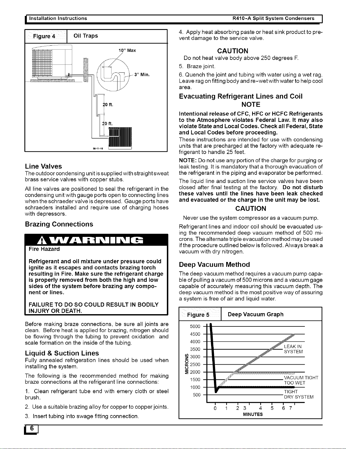
Deep Vacuum Method
The deep vacuum method requires a vacuum pump capa-
ble of pulling a vacuum of 500 microns and a vacuum gage
capable of accurately measuring this vacuum depth. The
deep vacuum method is the most positive way of assuring
a system is free of air and liquid water.
Figure 5
5000
4500
4000
3500
3000
2500
o
2000
1500
1000
50O
Deep Vacuum Graph
LEAKIN
SYSTEM
VACUUM TIGHT
TOO WET
TIGHT
DRY SYSTEM
0 1 23 4 5 67
MINUTES
Loading ...
Loading ...
Loading ...