Safety Precautions
Before trying to use the instrument, be sure to read the
separate “Safety Precautions”.
E
XWG1-E-1B
USER’S GUIDE
Please keep all information for future reference.
XW
-
G1

NOTICE
This equipment has been tested and found to comply with the limits for a Class B digital device, pursuant to Part 15 of the
FCC Rules. These limits are designed to provide reasonable protection against harmful interference in a residential
installation. This equipment generates, uses and can radiate radio frequency energy and, if not installed and used in
accordance with the instructions, may cause harmful interference to radio communications. However, there is no guarantee
that interference will not occur in a particular installation. If this equipment does cause harmful interference to radio or
television reception, which can be determined by turning the equipment off and on, the user is encouraged to try to correct
the interference by one or more of the following measures:
• Reorient or relocate the receiving antenna.
• Increase the separation between the equipment and receiver.
• Connect the equipment into an outlet on a circuit different from that to which the receiver is connected.
• Consult the dealer or an experienced radio/TV technician for help.
FCC WARNING
Changes or modifications not expressly approved by the party responsible for compliance could void the user’s authority to
operate the equipment.
Declaration of Conformity
Model Number: XW-G1
Trade Name: CASIO COMPUTER CO., LTD.
Responsible party: CASIO AMERICA, INC.
Address: 570 MT. PLEASANT AVENUE, DOVER, NEW JERSEY 07801
Telephone number: 973-361-5400
This device complies with Part 15 of the FCC Rules, Operation is subject to the following two conditions:
(1) This device may not cause harmful interference, and (2) this device must accept any interference received, including
interference that may cause undesired operation.
Important!
Please note the following important information before using this product.
• Before using the optional AC Adaptor to power the unit, be sure to check the AC Adaptor for any damage first. Carefully check
the power cord for breakage, cuts, exposed wire and other serious damage. Never let children use an AC adaptor that is
seriously damaged.
• Never attempt to recharge batteries.
• Do not use rechargeable batteries.
• Never mix old batteries with new ones.
• Use recommended batteries or equivalent types.
• Always make sure that positive (+) and negative (–) poles are facing correctly as indicated near the battery compartment.
• Replace batteries as soon as possible after any sign they are getting weak.
• Do not short-circuit the battery terminals.
• The product is not intended for children under 3 years.
• Use only a CASIO AD-E95100L adaptor.
• The AC adaptor is not a toy.
• Be sure to disconnect the AC adaptor before cleaning the product.
This mark applies in EU countries only.
Manufacturer:
CASIO COMPUTER CO., LTD.
6-2, Hon-machi 1-chome, Shibuya-ku, Tokyo 151-8543, Japan
Responsible within the European Union:
CASIO EUROPE GmbH
Casio-Platz 1, 22848 Norderstedt, Germany
● Any reproduction of the contents of this manual, either in part or its entirety, is prohibited. Except for your own, personal
use, any other use of the contents of this manual without the consent of CASIO is prohibited under copyright laws.
● IN NO EVENT SHALL CASIO BE LIABLE FOR ANY DAMAGES WHATSOEVER (INCLUDING, WITHOUT LIMITATION,
DAMAGES FOR LOSS OF PROFITS, BUSINESS INTERRUPTION, LOSS OF INFORMATION) ARISING OUT OF THE
USE OF OR INABILITY TO USE THIS MANUAL OR PRODUCT, EVEN IF CASIO HAS BEEN ADVISED OF THE
POSSIBILITY OF SUCH DAMAGES.
● The contents of this manual are subject to change without notice.
● The actual appearance of the product may be different from that shown in the illustrations in this User’s Guide.
● Company and product names used in this manual may be registered trademarks of others.
E-1

E-2
Contents
General Guide ............................. E-5
Getting Ready to Play ................ E-8
Connections ...............................................E-8
Power Supply .............................................E-9
Using a Household Power Outlet ............................E-9
Using Batteries...................................................... E-10
Auto Power Off...................................................... E-10
Bundled and Optional Accessories ..........E-10
Learning to Play by Playing
(For Synthesizer Novices) ....... E-11
Playing with Built-in Tones .......................E-11
Creating Tones.........................................E-12
Using the Step Sequencer and
Phrases ....................................................E-13
Arpeggio Function .................................................E-13
Phrase Sequencer ................................................E-14
Step Sequencer ....................................................E-14
Recording and Looping a Sample............E-15
Using the Performance Function..............E-16
Playing a Built-in Demo Song ..................E-17
Conclusion ...............................................E-17
Selecting and
Creating Tones ......................... E-18
Overview ..................................................E-18
To select a tone........................................E-19
To edit and save a tone as a user tone....E-20
Editable Parameters for
Solo Synthesizer Tone ..........................................E-21
Editable Parameters for PCM Melody Tone
(Non-drum PCM Tones)........................................E-30
Editable Parameters for Drum PCM Tone............. E-31
Editable Parameters for User Wave Tone.............E-32
Controlling Sounds .................................. E-34
Using a Pedal ....................................................... E-34
Using the Wheels (Bender, Modulation) ............... E-34
Using the Assignable Knobs................................. E-34
Using Sliders......................................................... E-34
Using the Hold Button ........................................... E-36
Changing the Pitch of Notes in Semitone Steps
(Transpose) or Octave Steps (Octave Shift)......... E-36
Applying Effects to Notes ........................ E-36
To configure effect settings................................... E-37
Saving an Edited DSP .......................................... E-39
Sounding Arpeggios
Automatically ............................ E-40
To use the Arpeggio Function ................. E-40
Editing an Arpeggio ................................. E-41
Clearing Arpeggio Data ........................... E-44
Recording and Playing Back
Phrases...................................... E-45
To play back a preset .............................. E-45
To change the tempo setting ................................ E-46
You can use the phrase selection screen to
select the recommended tone for the currently
selected phrase as your Zone Part 1 tone. ........... E-46
To start phrase playback by
pressing keyboard key (Key Play) ........... E-46
Recording a New Phrase ........................ E-47
Phrase Data Settings ............................................ E-48
Recording Over Another Phrase
(Overdubbing) ......................................... E-48
Indicators Next to Phrase Numbers......... E-49
To save a phrase..................................... E-49

Contents
E-3
Using the Step Sequencer ....... E-50
How the Step Sequencer is organized.....E-50
Playing Back a Step Sequence................E-52
Editing a Sequence -Simple Editing.........E-52
To turn a step on or off ..........................................E-53
To configure tied note settings ..............................E-53
Using the Sliders to Change Note and
Velocity Settings....................................................E-53
Using the Master Slider to Change Note and
Velocity Settings....................................................E-54
Changing Slider Assignments ...............................E-54
Changing the Function Assigned to the
Master Slider ......................................................... E-54
Inputting Step Data by
Playing on the Keyboard, etc. ...............................E-55
Changing the Solo1 Channel ................................E-55
Changing the Timing of Pattern Switching ............E-56
Syncing Step Sequencer Playback with an
Arpeggio................................................................ E-56
Changing the Step Sequencer Tone........E-56
To sound a single part (solo mode)..........E-56
Editing a Sequence - Advanced...............E-56
To perform advanced parameter editing ............... E-56
Changing Slider Settings..........................E-60
To copy slider settings from another slider............ E-60
To save an edited sequence ....................E-61
Chaining ...................................................E-61
To create a chain .................................................. E-61
To play back a chain .............................................E-62
To initialize chain settings .....................................E-62
To save a chain in SMF format to
a memory card ......................................................E-63
Recording and Playing Back
with the Sample Looper ........... E-64
Sample Recording....................................E-64
To record with the sample looper.............E-64
To use the Step Sequencer to
record a sample .......................................E-69
To play back a sample .............................E-69
Indicators Next to Sample Numbers ........E-70
To save a sample.....................................E-70
Using the Performance
Mode........................................... E-71
Overview ................................................. E-71
Registering and Recalling
Performances .......................................... E-71
To register a performance .................................... E-71
To recall a performance ........................................ E-72
Editable Performance Parameter List...... E-73
Other Useful Functions ............ E-78
Using the Mixer ....................................... E-78
Instant Adjustment of Settings using the
Sliders and Step Buttons ...................................... E-79
Mixer Settings ....................................................... E-80
Global Synthesizer Settings .................... E-81
Tuning (Fine tuning of note pitch) ......................... E-81
Local Control......................................................... E-81
Master Coarse Tune
(Tuning of note pitch in semitone steps) ............... E-81
Initial Power On Mode .......................................... E-81
Display Contrast ................................................... E-81
Auto Power Off On/Off.......................................... E-81
Using MIDI............................................... E-82
What is MIDI? ....................................................... E-82
MIDI Settings ........................................................ E-82
Deleting Data Saved on the
Synthesizer.............................................. E-83
Initializing Synthesizer Global Settings
and Data .................................................. E-84
Playing a Demo Tune or a File from a
Memory Card........................................... E-84

Contents
E-4
Using a Memory Card............... E-86
Supported Data Types ..........................................E-86
Card and Card Slot Precautions ........................... E-87
Loading and Removing a
Memory Card ...........................................E-87
Formatting a Memory Card ......................E-88
Saving Synthesizer Data to a
Memory Card ...........................................E-88
To save Synthesizer data to a memory card.........E-88
To batch save all Synthesizer data to a
memory card .........................................................E-89
Loading Data from a Memory Card..........E-90
To load data to Synthesizer memory from a
memory card .........................................................E-90
To batch load all Synthesizer memory data
from a memory card ..............................................E-90
To delete a file from a memory card ........E-90
To rename a file on a memory card .........E-91
Playing a Music File from a
Memory Card ...........................................E-91
Connecting to a Computer ...... E-92
Minimum Computer System
Requirements...........................................E-92
Connecting the Synthesizer to Your Computer ..... E-92
Saving and Loading Synthesizer Data
to a Computer and Editing Synthesizer
Data on a Computer.................................E-93
Reference .................................. E-94
Error Messages........................................E-94
Troubleshooting .......................................E-95
Specifications ...........................................E-97
Operating Precautions .............................E-98
DSP Effect List .........................................E-99
DSP Type List .......................................................E-99
DSP Parameter List ............................................E-100
Supported Input Characters ...................E-103
MIDI Implementation Chart
E-5
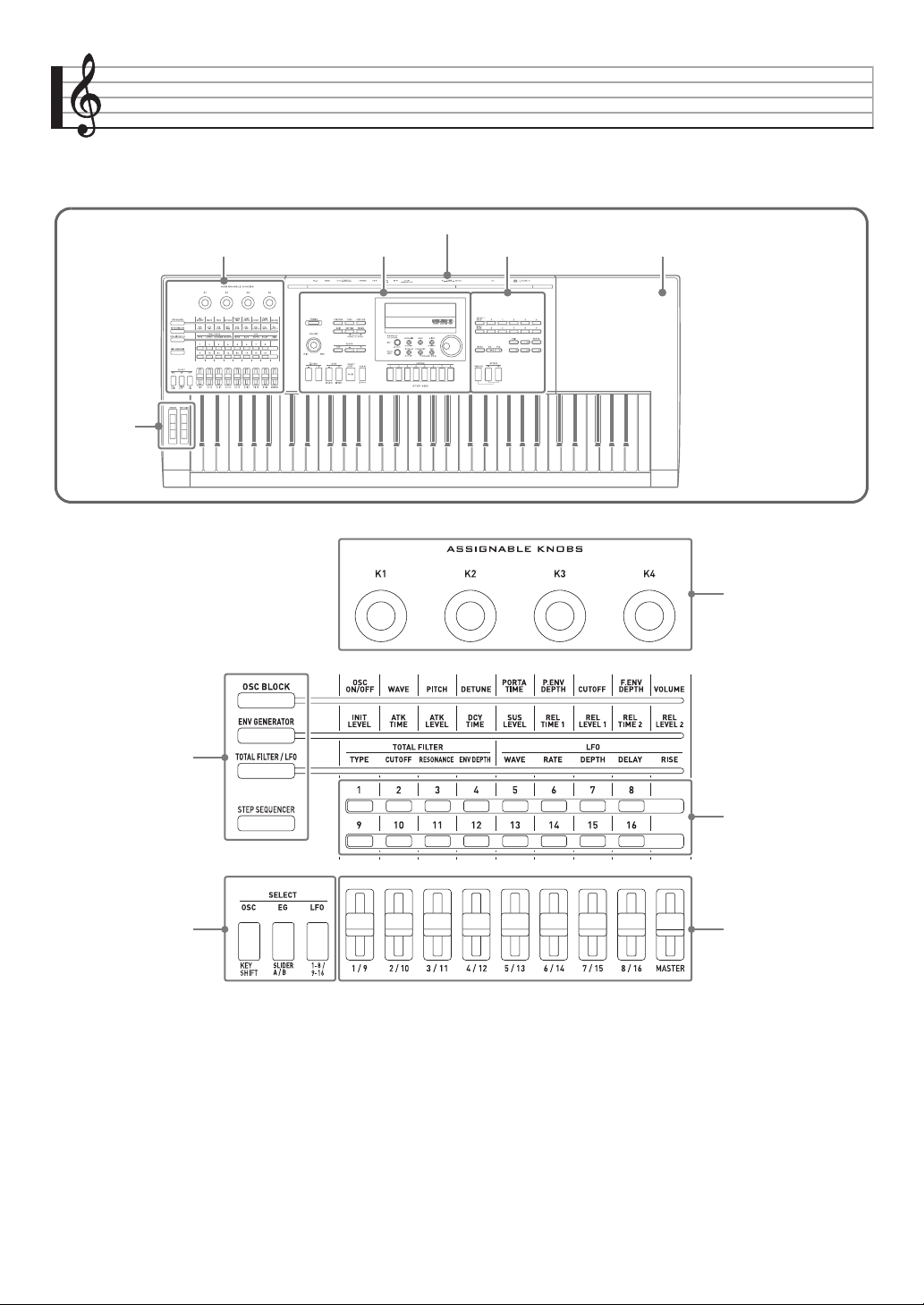
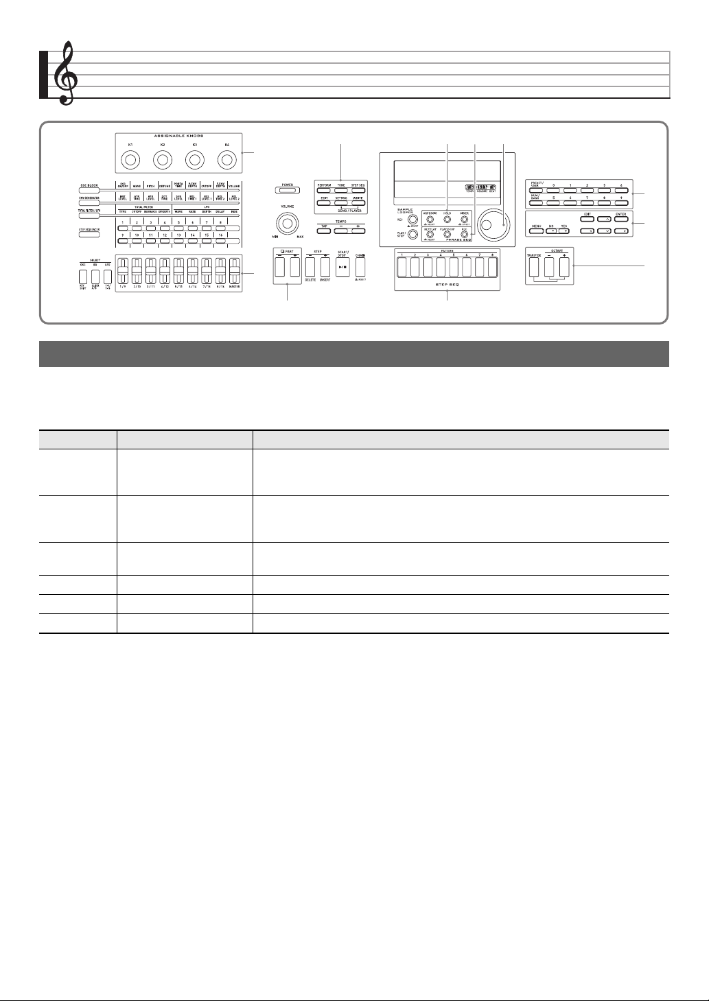
General Guide
• In this manual, buttons, knobs, terminals, and other parts are referred to using a combination of group numbers
(
1
,
2
, etc.) and part names.
Groups
1
through
5
are laid out to facilitate adjustment of a sound as you listen to it.
1
Use these buttons to select the functions assigned to the sliders (
5
) and
2
buttons. ☞ Page E-34
2
Use these buttons when editing Solo Synthesizer tones and to change parts assigned to the sliders (
5
). ☞ Page E-23
3
Use these knobs to adjust attack, decay, and other sound parameters. ☞ Page E-34
4
Use these buttons with the step sequencer to turn each step or part on or off. ☞ Page E-53
5
Use these sliders to adjust parameters. They are also used for editing with the step sequencer and mixer.
☞ Page E-34, E-53, E-78
Left Center Right Tray
Back
Lower left
• The tray is angled slightly.
Take care so items placed
on it do not slide off.
• Do not place cups or any
other liquid containers on
the tray.
1
3
4
5
2
(Sliders)
Left
General Guide
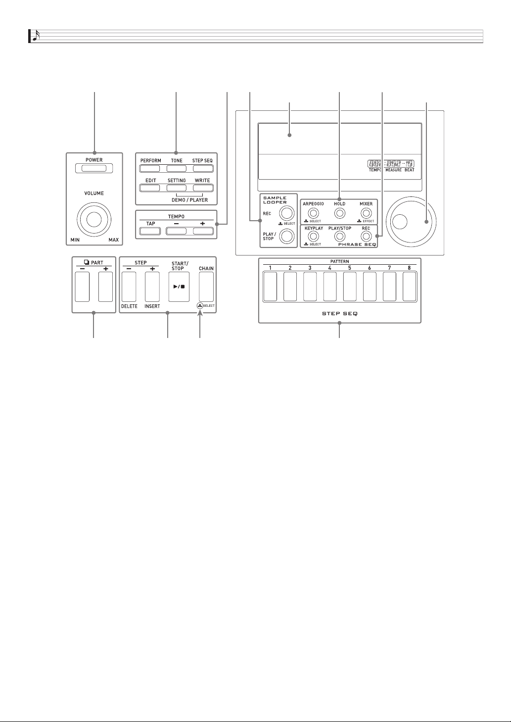
E-6
6
Use the [POWER] button to turn power on or off, and the [VOLUME] knob to adjust the volume level. ☞ Page E-9
7
Use the top three buttons to select the Synthesizer’s mode. Use the bottom three buttons to edit and save tone and other
data, and to configure system-wide general settings. ☞ Page E-11, E-12, E-81
8
Use these buttons to adjust the tempo of the step sequencer, phrase, and other playback. ☞ Page E-46
9
Use these buttons to select a part for editing with the step sequencer or mixer. ☞ Page E-52, E-78
bk
Use these buttons to select a step for step sequencer playback or editing. ☞ Page E-52
bl
Use these buttons to select a step sequencer pattern. ☞ Page E-11, E-52
bm
Use these buttons for sample looper recording and playback. ☞ Page E-64
bn
Use these buttons to turn the arpeggio and hold functions on or off, and to change mixer or effect settings.
☞ Page E-37, E-40, E-78
bo
Use these buttons to perform phrase sequencer recording and playback. ☞ Page E-45
bp
Use the dial for quick change of the numbers and values that appear on the display. ☞ Page E-11
6
9
bk bl
7
bn
8 bm bo bp
Center
LCD
Indicates name of function
when button is held down.
(Dial)
General Guide
E-7
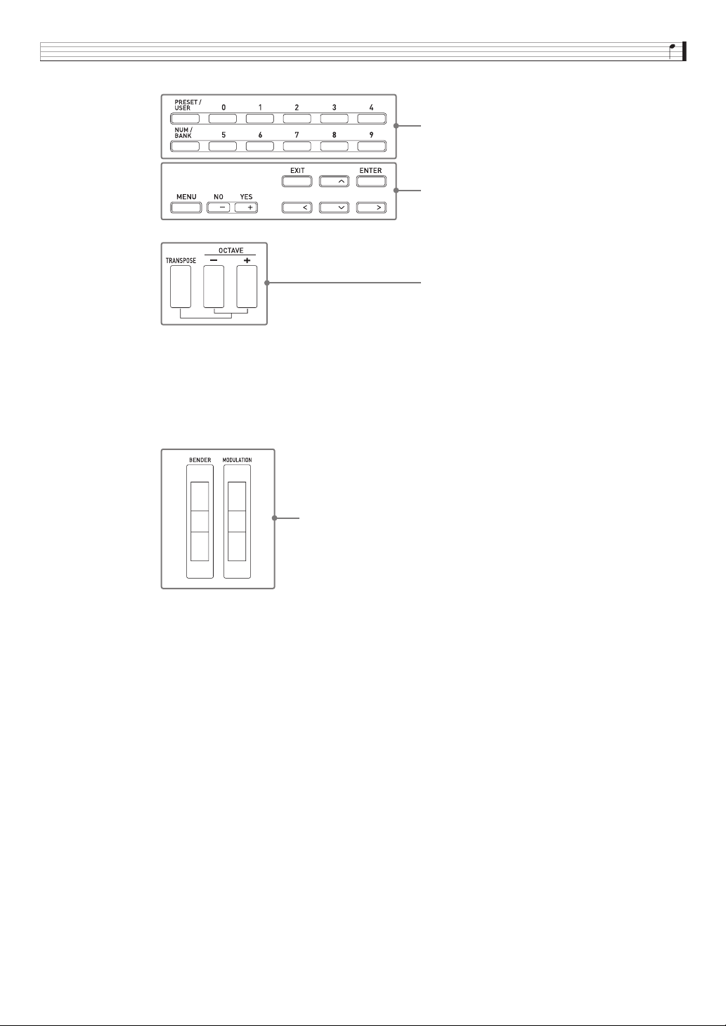
bq
Use these buttons to select a tone number, performance number, etc. ☞ Page E-19
br
Use the six buttons on the right to move the cursor on the screen, and the minus (–) and plus (+) buttons to change a
displayed value. Press the [MENU] button to display a menu of options for the operation you are currently performing.
☞ Page E-20
bs
Use these keys for one-touch alteration of the pitch of a sound. ☞ Page E-36
bt
Use [BENDER] to bend notes and [MODULATION] to add vibrato to notes. ☞ Page E-34
Back
See the next page.
bq
br
bs
Right
bt
Lower left
E-8
Getting Ready to Play
• Whenever you connect any device to the Synthesizer, be sure to read the user documentation that comes with the device.
• This Synthesizer does not have built-in speakers. It will not produce sound unless you connect some device for sound output.
ck
Back left
cl
Back right
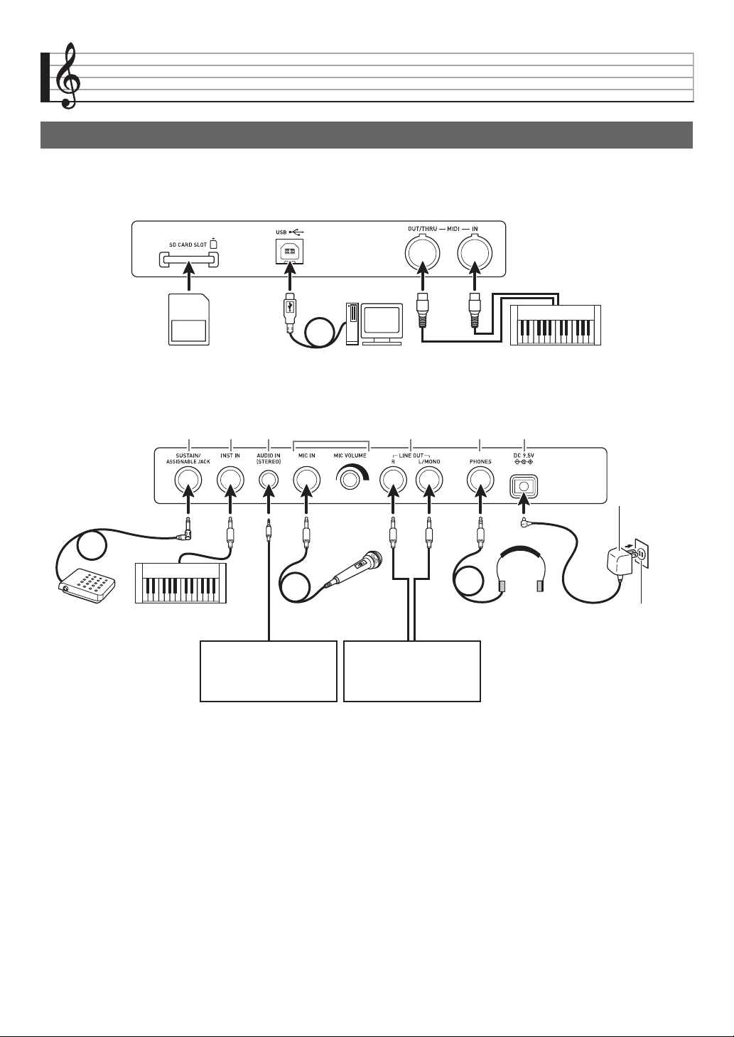
Connections
Memory card (page E-86) Computer (page E-92) Other electronic music instrument (page E-82)
(1) (2) (3) (5) (6) (7)(4)
*1 Standard plug (monaural)
*2 Stereo standard plug
*3 Stereo mini plug
Pedal Microphone Headphones Household
power outlet
CD player, audio player,
etc.
Audio device, amplifier, etc.
Other electronic music
instrument
*1 *3 *1 *1 *1 *2
Configuration
and type
depends on your
geographic
location.
Getting Ready to Play
E-9
Prepare a household power outlet or batteries.
• Be sure to comply with the separate “Safety
Precautions”. Incorrect use of this product creates the
risk of electric shock and fire.
• Always make sure that the product is turned off before
plugging in or unplugging the AC adaptor, or before
loading or removing batteries.
Make sure that you use only the AC adaptor (JEITA Standard,
with unified polarity plug) specified for this product. Use of a
different type of AC adaptor can cause malfunction.
1.
Use the AC adaptor specified for this
Synthesizer to connect it to a household power
outlet.
2.
Press
6
POWER to turn on power.
• To turn off power, press
6
POWER again.
To do this: Do this:
(1) Use a pedal Connect an optionally available sustain pedal. For information about the type of
effect applied when the pedal is depressed, see page E-74.
(2) Input sound from another electronic
musical instrument
Use a commercially available connecting cord to connect the output terminal
(monaural) of the other instrument to the Synthesizer.
*4
• You can also apply effects to input sounds (page E-36) and use input sounds
when creating new tones as part of the Synthesizer’s tones (page E-21).
(3) Input from an external device Use a commercially available connecting cord to connect the output terminal
(stereo) of a CD player or portable audio player to the Synthesizer.
*4
(4) Input external sound using a
microphone
Connect a commercially available dynamic microphone to the Synthesizer.
*4
You can use
cl
MIC VOLUME to adjust sound input with the microphone
independently of other sound.
• For information about applying effects to sound input with a microphone, see
page E-78. For information about using input sounds for tone creation, see
page E-21.
(5) Output Synthesizer sound using audio
equipment or an amplifier
Use a commercially available connecting cord to connect the input terminal
(AUX IN, etc.) of the audio equipment or amplifier to the Synthesizer.
*4
• For monaural output with a single connecting cord, connect the cord to the
L/MONO terminal of the Synthesizer.
(6) Use headphones Connect optional or commercially available headphones to the Synthesizer.
*4
• Do not listen to music at very loud volumes for long periods. Doing so creates
the risk of hearing damage.
(7) Supply power to the Synthesizer See “Power Supply” below.
*4 Before connecting, be sure to turn off power to the Synthesizer and the device being connected, and turn
6
VOLUME down
to a low level.
Power Supply
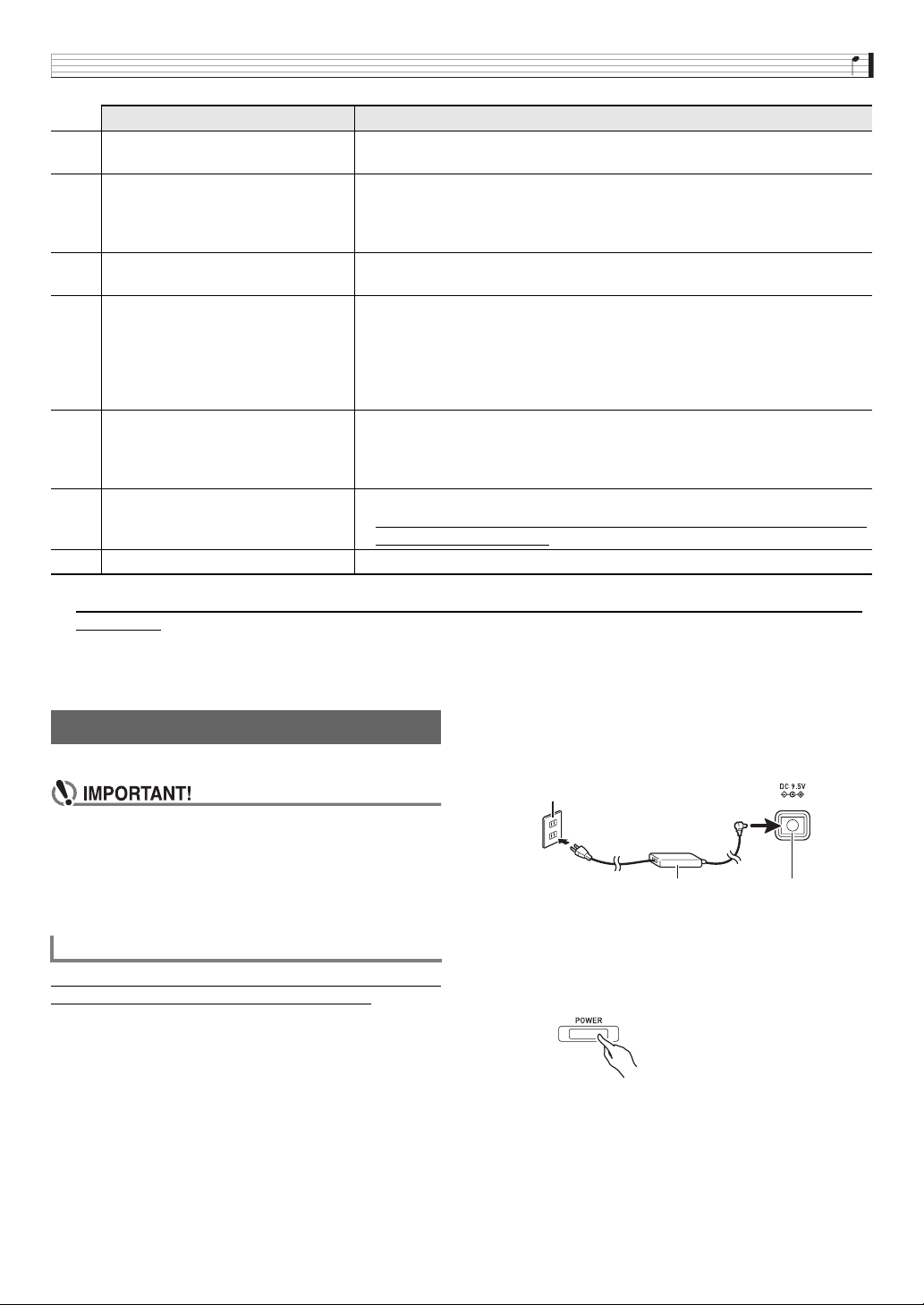
Using a Household Power Outlet
Specified AC Adaptor: AD-E95100L
6
AC adaptor
• Configuration and type
depends on your
geographic location.
DC 9.5V
Household power outlet
Getting Ready to Play
E-10
• If you press
6
POWER only lightly, the display will
light up momentarily but power will not turn on. This
does not indicate malfunction. Press
6
POWER firmly
and completely to turn on power.
• The AC adaptor will become warm to the touch after
very long use. This is normal and does not indicate
malfunction.
• To prevent breaking of the wire, take care to avoid
putting any type of load on the power cord.
• Never insert metal, pencils, or any other objects into
the product’s 9.5V DC terminal. Doing so creates the
risk of accident.
You can use six D-size batteries for power.
• Use alkaline or zinc-carbon batteries.
Never use oxyride or any other nickel based batteries.
1.
Open the battery cover on the bottom of the
Synthesizer.
2.
Load six D-size batteries into the battery
compartment.
• Make sure the positive + and negative - ends of the
batteries are facing as shown in the illustration.
3.
Insert the tabs of the battery cover into the
holes on the side of the battery compartment,
and close the cover.
4.
Press
6
POWER to turn on power.
■ Low Battery Indication
The following shows the approximate battery life.
Approximately 35 hours* (alkaline batteries, using the
optional CASIO CP-16 headphones)
* Using a high volume setting, playing in very low
temperatures, and certain other playing conditions can
shorten battery life.
Low battery power is indicated when the message “Battery
Low” appears and the indicators shown below flash on the
display. Replace the batteries with new ones.
The Synthesizer turns off automatically to avoid wasting
power if no operation is performed for a preset amount of
time. The Auto Power Off trigger time is six minutes under
battery power and four hours under AC adaptor power.
• You can disable Auto Power Off by turning off the “Auto
Power Off” setting as described under “Global Synthesizer
Settings” (page E-81).
Use of unauthorized accessories creates the risk of fire,
electric shock, and personal injury.
• You can get information about accessories that are sold
separately for this product from the CASIO catalog
available from your retailer, and from the CASIO website at
the following URL.
http://world.casio.com
/
No bending! No winding!
Using Batteries
Tabs
Auto Power Off
Bundled and Optional
Accessories
Low battery indication (flashing)
E-11
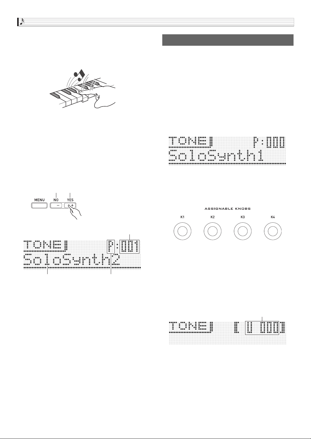
Learning to Play by Playing (For Synthesizer Novices)
This chapter gets you started with basic operations by actually
using the Synthesizer, while avoiding getting too bogged
down in theory and technical details. It is the perfect place to
start for those who are using a synthesizer for the first time.
So, let’s get started!
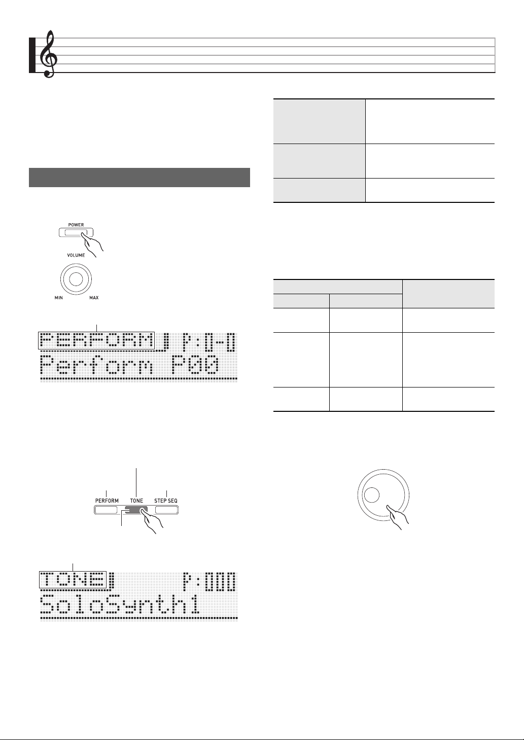
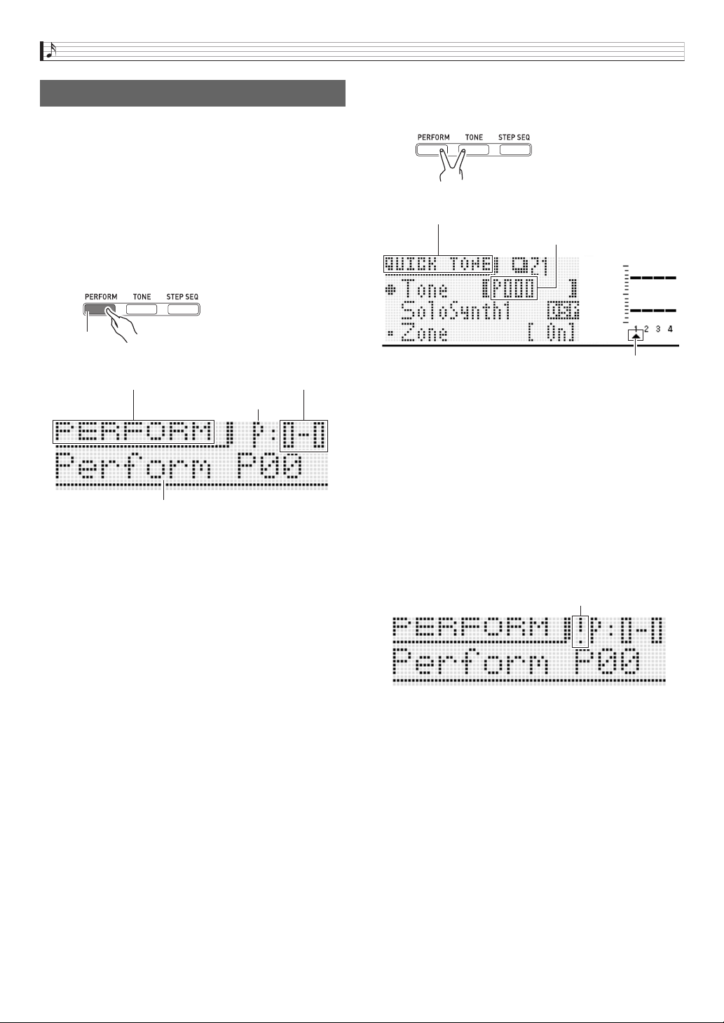
Press
6
POWER to turn on power. The Synthesizer initially
enters its Performance Mode.
The Performance Mode is great for tapping to the full power of
the Synthesizer during performances, but it is a bit too
advanced for our basic explanation here. For now, let’s start
out with some basic operations in the Tone Mode.
Press
7
TONE to enter the Tone Mode.
■ Three Synthesizer Modes
Here, let’s select a tone hear what it sounds like.
Tones are divided among four categories. Rotate the
bp
dial
to select the tone number you want. Alternately, you could
also use the
bq
buttons to input specific tone numbers (page
E-19).
• For more information, see page E-19.
First, let’s see what a Solo Synthesizer tone sounds like.
Rotate the
bp
dial to select a tone number.
Playing with Built-in Tones
6
7
Performance Mode
Performance Mode
Tone Mode
Step Sequencer Mode
Lit
Tone Mode
Performance Mode
Use this mode for playing and
performing. It enables high-level
performance with tone categories,
a Step Sequencer, and more.
Tone Mode
Use this mode for tone creation.
You can select a single tone and
edit it the way you want.
Step Sequencer Mode
This mode is for creating step
sequencer data (sets).
Category
Overview
Number Name
P000 to P099 Solo Synthesizer
Traditional analog
synthesizer tones
P100 to P399
PCM Melody Tone
PCM Drum Tone
These tones let you use
sampled sounds to
reproduce the sounds
from a variety of
different instruments.
– User Wave Tone
Save of tones recorded
with the sample looper.
Learning to Play by Playing (For Synthesizer Novices)
E-12
Play something on the keyboard to hear what the tone sounds
like. Use
6
VOLUME to adjust the volume.
• Note that the Solo Synthesizer tones are monophonic. If
you press multiple keys, only the note of the last key
pressed will sound.
Solo Synthesizer actually is a category that contains 100
built-in (preset*) tones. What we played here is just one of
them. Now let’s play some more of the preset tones in this
category.
* There are also “user tones” which are those that you create
and store for later recall. The terms “preset” and “user” are
also used for other types of data, such as Step Sequencer
data, performance data, etc.
Press the
br
plus (+) button. Each press increases the
preset tone number and changes the tone setting.
You can use the same operations to select the tones in the
other categories besides Solo Synthesizer, so experiment for
yourself to find out what tones are available.
Tone creation is actually what using a synthesizer is all about.
Starting from a preset tone, you can change various
parameters to create a tone that is your own original sound.
With this setting, pressing the
7
EDIT button provides you
with a collection of powerful editing capabilities (page E-20).
In addition, you also can use the
5
sliders to easily alter
tones without using the
7
EDIT button. Here we will take a
simplified look at editing a Solo Synthesizer tone. This
process is covered in greater detail later in this manual.
Press
7
TONE and then rotate the
bp
dial to select a tone
number.
Play some notes on the keyboard. As you do, rotate the
3
ASSIGNABLE KNOBS. This will change the characteristics
of the tone that is sounding. Make adjustments until the tone
sounds the way you want.
Example: Rotating K1 while P:000 is selected as the tone
After you are finished, you can save the result as a user tone.
Press
7
WRITE to enter the save mode. The save
destination will appear on the display screen.
Use the
bp
dial or
br
minus (–) and plus (+) buttons to
specify the tone number where you want to save your user
tone.
br
Back Forward
Tone number
Tone name P: Preset
U: User
Creating Tones
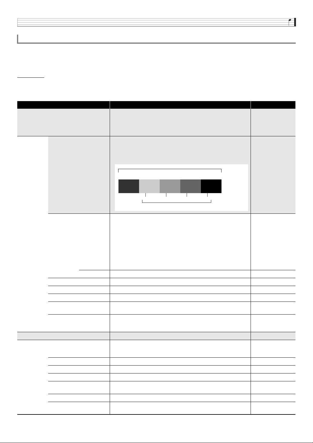
• Rotate right to make the tone brighter.
• Rotate left to make the tone darker.
Save destination
U: User number
000: Tone Number 000
Learning to Play by Playing (For Synthesizer Novices)
E-13
Next, press the
br
down (w) button to change to the tone
name input screen.
Example:
Use the
br
left (U) and right (I) buttons to move the cursor
between input positions, and the
bq
tone number buttons to
input characters.
• The illustration below shows the letters that each of the
bq
tone number buttons inputs. Each press of a button
cycles through the letters or toggles between the settings
assigned to it. For information about what types of
characters are supported, see page E-103.
• You also can use the
br
minus (–) and plus (+) buttons
or the
bp
dial to scroll through characters.
After the tone name is the way you want, press
br
ENTER.
This will cause “Replace?” (Do you want to replace the current
tone?) to appear on the display.*
1
Press
br
YES to save the user tone.*
2
*1 Saving data to a tone number deletes any data that was
previously assigned to that number.
*2 If you do not want to save the data, press
br
NO instead
of YES.
• We recommend that you back up all data stored in
Synthesizer memory to a memory card or a computer hard
disk. To save data to a memory card, see “Using a Memory
Card” (page E-86). To save data to a computer, see
“Connecting to a Computer” (page E-92).
To recall a stored user tone, use the same procedure as that
for recalling preset tones. Let’s try recalling the tone we just
saved.
• Before specifying the tone number, press
bq
PRESET/
USER to enter the user tone select mode.
At this point you have mastered the simplest steps required to
edit and save tones. But you shouldn’t stop here. Your
Synthesizer has a wealth of other tone editing features,
functions, and tools. Take the time to learn about these and
you will become capable of high-level tone editing. Find out
more under “Selecting and Creating Tones” on page E-18.
Your Synthesizer does much more than create tones. It is also
equipped with a collection of functions that support uniquely
expressive rhythms and phrases that enhance your
performances. This section provides a simple introduction to
some of these functions.
Press
bn
ARPEGGIO so the button becomes lit.
Press any key on the keyboard. The arpeggio function will
cause the note assigned to the key to play in an endless loop.
The loop will stop when you release the keyboard key.
Pressing two or three keyboard keys will loop play the notes
of the keys you press. Pressing three or more keys will cause
an arpeggio (sometimes referred to as a “broken chord”) to be
played.
Cursor: Input position
Symbols (Part 1)
Numerals
ABC DEF GHI JKL
(Upper/lower case toggle)
MNO PQRS TUV WXYZ
Symbols (Part 2)
bq
Using the Step Sequencer and
Phrases
Arpeggio Function
bn
Lit (Indicates user tone selected.)
User tone
Lit
Learning to Play by Playing (For Synthesizer Novices)
E-14
There are a variety of different built-in arpeggio types. You
can select one the same way as you select a preset tone, edit
it, and then save it as a user arpeggio type. Let’s go over the
procedure for selecting a preset arpeggio type.
• The arpeggios of this Synthesizer are divided into 10 type
groups called “banks”. There are a total of 10 arpeggio
banks numbered 0 through 9, with 10 arpeggios in each
bank for a total of 100 arpeggios.
Hold down
bn
ARPEGGIO until the screen shown below
appears on the display.
Now rotate the
bp
dial and select a preset phrase type the
same way you select a tone (page E-11).
For details about arpeggios, see “Sounding Arpeggios
Automatically” on page E-40.
To give you an idea about what a musical phrase is, let’s
listen to a preset phrase.
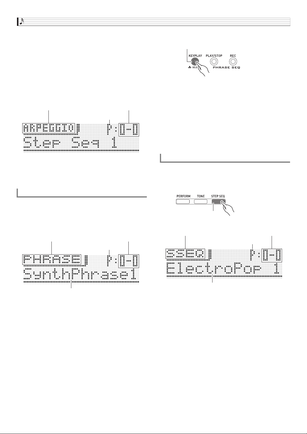
Hold down
bo
KEY PLAY until the screen shown below
appears on the display.
Press
bo
PLAY/STOP. This will start playback of one of the
Synthesizer’s built-in preset phrases. Next, try rotating the
bp
dial and selecting other preset phrases.
Instead of using
bo
PLAY/STOP, you can also start playback
of a phrase by pressing a key on the keyboard. Let’s see how
this works.
First, press
bo
KEY PLAY so the button becomes lit.
This is Key Play Mode. Pressing a keyboard key while in the
Key Play Mode will automatically start playback of a phrase.
Pressing another key will play the phrase using a different
pitch. In the Key Play Mode, the keyboard can be used to
sequentially play a phrase at different pitches to create an
interesting effect.
The Phrase Sequencer main chapter covers information
about how you can record your own phrases and play them
back when you want to. For more information see “Recording
a New Phrase” on page E-47.
Let’s start out our explanation of the Step Sequencer by
listening to some preset sequence data.
Press
7
STEP SEQ to enter the Step Sequencer Mode.
Phrase Sequencer
Screen title (arpeggio type) Bank-Type number
Preset
Phrase Sequencer Mode Bank-Phrase number
Preset
Phrase name
bo
Step Sequencer
7
Lit
Lit
Step Sequencer Mode Bank-Sequence number
Preset
Sequence name
Learning to Play by Playing (For Synthesizer Novices)
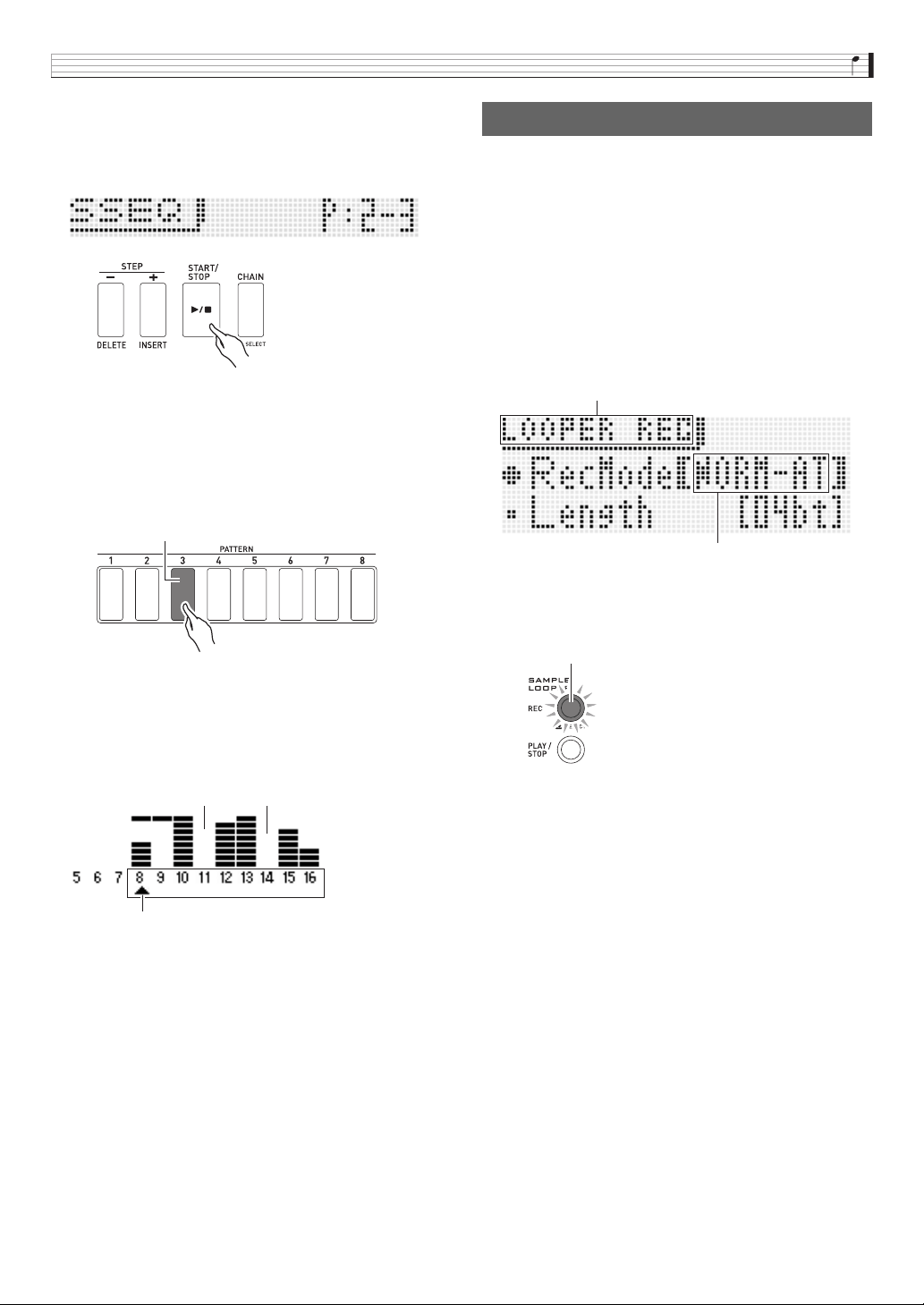
E-15
As you do when selecting a tone, you can use the
bp
dial to
select the sequence you want. For now, let’s select preset
sequence 2-3, and then press
bk
START/STOP. This will
start playback of the sequence you selected.
Each sequence has eight variations (patterns), which you can
select using the
bl
PATTERN 1 to 8 buttons. Experiment
with selecting the various patterns to get an idea of what is
available.
Example: To select Pattern 3
The Step Sequencer uses nine (8 through 16) of the 16 parts
of the Synthesizer’s sound source, which provides plenty of
support every for very complex rhythms. You can find out
which parts are outputting sound at any time by checking the
level meter on the Synthesizer’s display.
As the sequence plays back, the
4
buttons (1 to 16)
continually turn on and off, which indicates the movement of
the notes of the part that is being edited (the part indicated by
the pointer (e) in the illustration above. This is the way the
Step Sequencer repeatedly produces the 16 steps.
You can select a part for editing using the
9
PART minus
(–) and plus (+) buttons. Use the
5
slider to edit individual
steps. For more information, see page E-50.
What we have seen here is just a very small part of the many
and varied rhythms that can be produced by your Synthesizer.
Be sure to take a look at the procedure under “Using the Step
Sequencer” on page E-50 to find out how you can create your
own original sequences.
The following shows an simple example of how to use the
sample looper to sample a sound and create a loop.
Connect the other electronic music instrument from which you
want to record the sample or a microphone to the Synthesizer.
(See page E-8.)
Press
bm
REC to display the LOOPER REC (sample looper
recording setting) screen.
• Use the
br
cursor (q, w) buttons and the
br
minus
(–) and plus (+) buttons to change the “Rec Mode” setting
to “NORM-AT” and the “Length” setting to “04bt”.
Press
bm
REC again.
This will cause the
bm
REC button to flash. This operation
will enter the record auto start mode.
Output the sound on the other electronic music instrument or
microphone, or play something on the Synthesizer. The
Synthesizer will detect the sound and start recording.
• The
bm
REC button lights when recording starts.
After recording of four beats is complete, playback of a loop of
what was recorded starts automatically.
• The
bm
REC button starts flashing at high speed and
overdubbing is paused. Anything you play at this time is not
overdubbed into the sample, so you can play a duet with
what you recorded previously or practice for future
overdubbing.
When you are ready to start overdubbing, press
bm
REC
again. so the
bm
REC button light stops flashing and remains
lit.
• Whatever you play at this time is overdubbed on what you
recorded previously.
• Each press of
bm
REC toggles between loop playback and
overdubbing.
To stop recording, press
bm
PLAY/STOP.
For details, see “Recording and Playing Back with the Sample
Looper” (page E-64).
bk
bl
Lit: Selected pattern
Parts 11 and 14 unused
Part selected for editing (e)
Recording and Looping a Sample
bm
REC mode setting screen
Auto REC mode
Flashing
Learning to Play by Playing (For Synthesizer Novices)
E-16
If you have read all of the information in this introductory part
of the manual, you are finally ready to start using the
Performance function. In the Tone Mode, you saw how you
can select a single tone and play it on the keyboard. In the
Performance Mode, you can perform with up to four tones
simultaneously. You also can use the Performance Mode to
register tone, Step Sequencer, and other settings as setup
called a “Performance”. A Performance can be recalled at any
time, even while you are playing, to instantly change the
sequencer’s setup.
Press
7
PERFORM to enter the Performance Mode.
The Performance Mode keyboard uses the four tones
selected as Zone Part 1 through 4. For more information
about zone parts and their tones, see “Selecting and Creating
Tones” on page E-18.
• Solo Synthesizer tones can be assigned to Zone Part 1
only.
Always configure Zone Part 1 first. Press
7
PERFORM and
7
TONE at the same time to enter the Quick Tone Mode,
which you can use for simple Performance editing.
If the pointer (e) on the display is not under 1, use the
9
PART minus (–) and plus (+) buttons to move it to 1.
After ensuring that the pointer (e) is located at 1, use
bl
bp
bq
br
to select the tone for Zone Part 1.
Next, use the
9
PART minus (–) and plus (+) buttons to
move the display pointer (e) to 2 and then use the same
procedure as above to select a tone for Zone Part 2. Repeat
the above step for Zone Parts 3 and 4.
After selecting tones for each of the zone parts,
br
EXIT to
return to the Performance Mode screen. Next, play something
on the keyboard to see what it sounds like. All four of the
tones that you selected above should sound.
The exclamation point ( ! ) indicator on the display indicates
that there are pending edits that have not been saved yet.
Press
7
WRITE to enter the save mode. Next, perform the
same procedure that you used when saving a user tone to
save your user Performance data.
Using the Performance Function
7
Lit
Performance Mode Bank-Performance number
Preset
Performance name
7
Quick Tone Mode
Zone part tone being edited
Zone part being edited
Edits pending indicator
Learning to Play by Playing (For Synthesizer Novices)
E-17
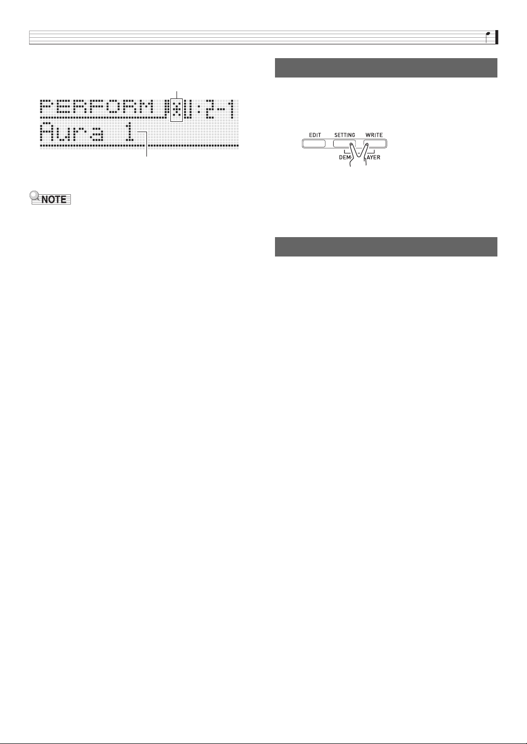
Example: To save the performance to User Bank 2,
Performance 1
• The edits pending indicator ( ! ) and edits saved indicator
( * ) are also used in other modes where data is edited and
saved (tones, Step Sequencer, etc.)
When you want to perform the song “Aura Lee”, simply recall
User Performance 2-1 to instantly configure the Synthesizer
with the four tones you registered above. Try recalling a
different Performance number and then recall User
Performance 2-1.
In addition to keyboard tones, you also can register a variety
of other settings as Performance data. An effective way to use
banks would be as song-specific banks. For example, Bank 2
for “Aura Lee”, Bank 3 for another song, etc. For more
information, see “Using the Performance Mode” on page
E-71.
Use the procedure below to play a built-in demo song that
shows off the full versatility of the Synthesizer.
Press
7
SETTING and
7
WRITE at the same time.
Next, press
br
ENTER. This will start demo tune play.
• Use the
br
minus (–) and plus (+) buttons to select a
different tune, and
bk
START/STOP to stop demo tune
play. For more information, see page E-84.
Tone number and other settings you configure on the
Synthesizer are retained even when you turn power off. For
information about returning settings to their initial defaults, see
“Initializing Synthesizer Global Settings and Data” on E-84.
This completes the section for synthesizer novices. See the
other sections of this manual for detailed information about
the topics covered briefly in this section. Take your time and
don’t rush, making sure you fully understand as you go along.
If you have problems with any of the terms used in this
manual, you can find more information by searching on the
Web or by consulting a reference book about synthesizers or
electronic music.
Soon you will be well on your way enjoying
the full potential of sound creation!
Edits saved indicator
Name indicating “Aura Lee” performance data
Playing a Built-in Demo Song
7
Conclusion
E-18
Selecting and Creating Tones
The tones of this Synthesizer are made up of the 16 parts shown below, plus externally input parts. This chapter explains how to
select, edit, and save tones using Zone Part 1
*
in the Tone Mode (page E-11).
It also covers the Effect Function that can be used to enhance tones and controllers that can be used to make various changes in
a tone as you play.
* About zones and zone parts
Keyboard, pedal, button, and other operations not only affect the Synthesizers preset tones, they are also sent as MIDI data and
affect any external device (electronic musical instrument or computer) connected to the Synthesizer.
The settings that apply to both internal and external parts are collectively referred to as a “zone” while the parts of the
Synthesizer’s built-in sound source that correspond to a zone is called “zone parts”. For example, if you select a tone with
Synthesizer Zone 2, that tone can be the part that corresponds to both the internal sound source Zone Part 2 or MIDI Channel 2
of an external device.
Overview
Part Number Part name Features
1 Zone Part1
*
This is the Synthesizer’s main part. This part is played whenever you play on the
keyboard. You can select the tone assigned to Zone Part 1 and edit the currently
assigned tone.
2 to 4 Zone Parts 2 through 4
*
These parts can be played only in the Performance Mode. Compared with Zone Part
1, your ability to assign and edit the tones assigned to these parts are limited (page
E-71).
5 to 6 Multi-function Key
These parts are used by Phrase 1 (Part Number 5) and Phrase 2 (Part Number 6),
which are assigned by the Multi-Function Key function (page E-73).
7 Guide, Precount Used by the guide and/or precount when recording a phrase (page E-47).
8 to 16 Drum 1 to Chord Step Sequencer Note Parts (page E-40).
– External Input These are tones that are input via the
cl
MIC IN, INST IN jacks (page E-78).
• You can change the relationships between zones and MIDI channels (page E-73).
9 bl
7
bn
bo bp
bq
br
bs
3
5
Selecting and Creating Tones
E-19
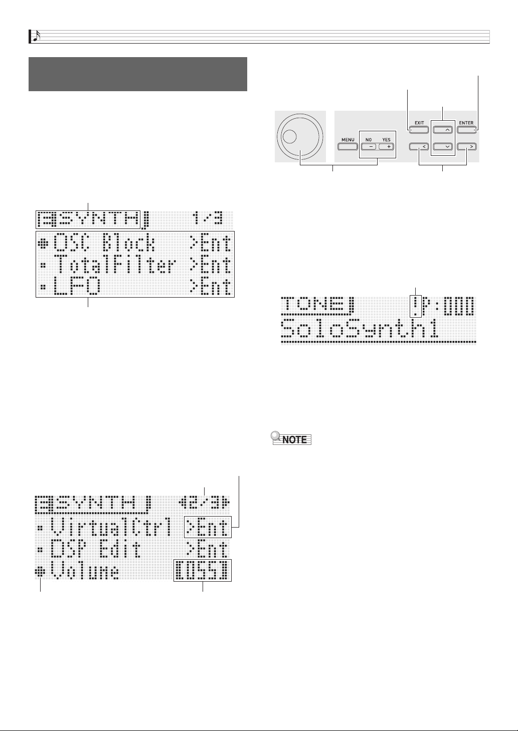
1.
Press
7
TONE.
The button will light and the Synthesizer will enter the Tone Mode.
2.
Press
bq
PRESET/USER to select preset tones or user tones.
• Preset tones are selected while the button is unlit, while user tones are selected while the button is lit.
3.
Use the
bq
number buttons (0 to 9) to input a tone number.
• You also can select a tone number by rotating the
bp
dial.
• One more way to change the tone number is to use the
br
minus (–) and plus (+) buttons to decrease or increase the
displayed number. Pressing the
br
minus (–) and plus (+) buttons at the same time will jump to the first tone in the current
selected category (see next section).
■ Tone Category Overview
• See the separate “Appendix” for a complete list of tones.
To select a tone
Category
Description
Number of Tones
Number
Name Preset User
Preset User
P000-P099 U000-U099 Solo Synthesizer
This category contains traditional analog synthesizer
tones. You can select a waveform as a base, and
then edit the three elements of a sound (pitch, tone,
volume) to create exactly the sound you want.
Monophonic.
100 100
P100-P399 U100-U199 PCM Melody Tone The tones in this category let you use sampled
sounds to reproduce the sounds from a variety of
different instruments.
300 100
P400-P419 U300-U309 PCM Drum Tone 20 10
– U200-U210 User Wave Tone
Edits the wave of a sound recorded with the sample
looper (page E-64). The wave of a sound can be
edited and saved as a user wave tone.
• User wave tone U210 is a tone that is changed in
real-time by sample looper recording.
–11
Zone Part 1 Zone Part 2 Zone Part 3 Zone Part 4
(MIDI
Channel 1)
(MIDI
Channel 2)
(MIDI
Channel 3)
(MIDI
Channel 4)
Zone 1
settings
Zone 2
settings
Zone 3
settings
Zone 4
settings
Built-in sound
source
External device
Selecting and Creating Tones
E-20
1.
Select the tone you want to edit.
• You can select a preset tone or an existing user tone
for editing.
2.
Press
7
EDIT.
This will display the top screen of the tone editing list.
Example: First page of the Solo Synthesizer tone editing
list
3.
Use
br
to select the item you want and change
the selected setting.
• You also can change setting by rotating the
bp
dial.
• For details about the displayed contents, see the
information presented for each tone category in the
sections of this manual from “Editable Parameters for
Solo Synthesizer Tone” (page E-21) to “Editable
Parameters for User Wave Tone” (page E-32).
Example: To select the “Volume” item on the top screen
and change its setting to 055
4.
After you finish with your edits, press
7
EDIT.
This exits the tone editing list.
• The edits pending indicator ( ! ) on the display indicates
that there are pending edits that have not been saved
yet. Your edits will be lost if you change to another
operation without saving them. Advance to step 5
below if you want to save your edits.
5.
Press
7
WRITE and then save your edited tone
as a user tone.
• For information about how to save user data, see the
procedure for saving user tone data (page E-12).
• For information about how to delete user tones, see
page E-83.
• The settings of some of the items on the tone editing list
can be changed using the Synthesizer’s sliders, without
going through the tone editing list. See “Controlling
Sounds” in the next section.
■ Saving User Tones to an External Device
• Memory card (page E-86)
• Computer (page E-92)
To edit and save a tone as a user
tone
List title
List
The options on this screen are groups, which are
made up of multiple items. Selecting a group and
pressing
br
ENTER will enter the group.
Page
Item selection Cursor Setting
brbp
Changes setting. Scrolls pages.
Selects item.
Enters a group.
Exits a group.
Edits pending indicator
Selecting and Creating Tones
E-21
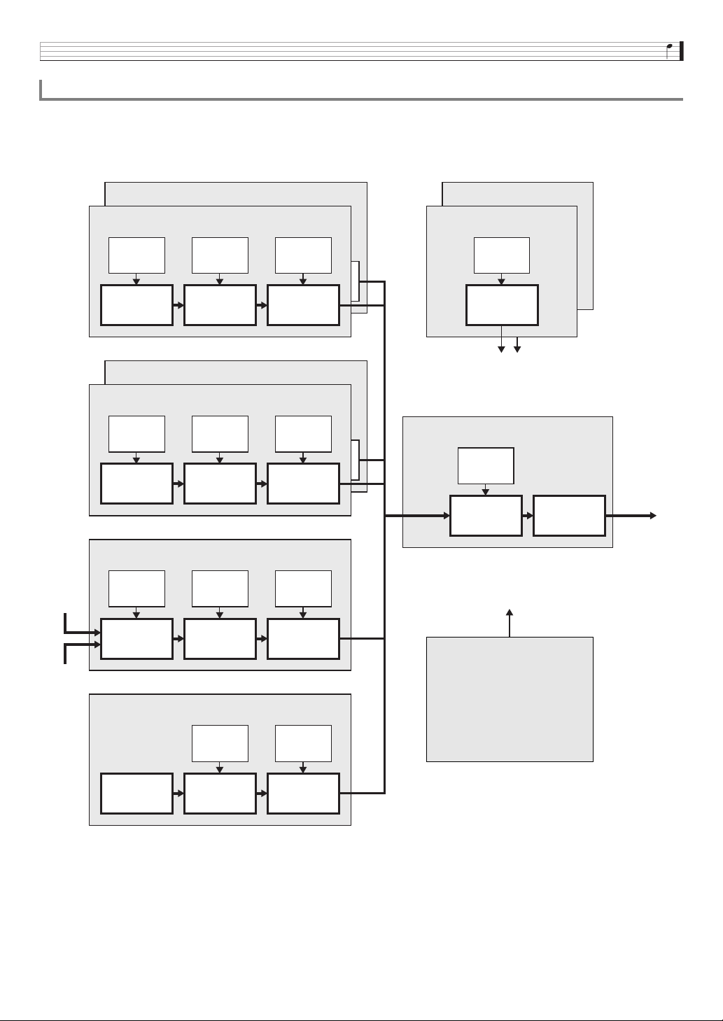
Solo Synthesizer tones are synthesized by combining tones of the six blocks, number (1) through (6), in the illustration below.
Before actually getting into tone editing, you should spend a little time becoming familiar with the structure and the details of each
block.
■ Solo Synthesizer Tone Configuration Diagram
* Envelope Generator
Editable Parameters for Solo Synthesizer Tone
MIC IN
INST IN
(1) Synth OSC1 Block
EG
*
EG
*
EG
*
Synth OSC Filter Amp
(2) Synth OSC2 Block
(3) PCM OSC1 Block
EG
*
EG
*
EG
*
PCM OSC Filter Amp
(4) PCM OSC2 Block
(5) External Input Sound Block
EG
*
EG
*
EG
*
Pitch shifter Filter Amp
(6) Noise Block
EG
*
EG
*
Noise
generator
Filter Amp
(8) LFO1 Block
EG
*
LFO
(9) LFO2 Block
(7) Total Block
EG
*
Filter
Solo
Synthesizer
DSP
Output
To blocks (1) through (9)
(10) Controllers
• Keyboard
• Pedal
•
bn
HOLD
• Bender
• Modulation
• MIDI receive messages
(Virtual controllers)
To blocks (1) through (7)
Selecting and Creating Tones
E-22
Description
(1) Synthesizer OSC1 Block
“OSC” is an abbreviation of “oscillator”, which is where a sound is actually produced. These two
synth OSC blocks creates sound using a sine wave, sawtooth wave, or other base waveform,
just like an analog synthesizer.
• Synth OSC: Generates the base sound and determines the pitch.
• Filter: Cuts some of the frequencies to adjust timbre.
• Amp: Adjusts volume.
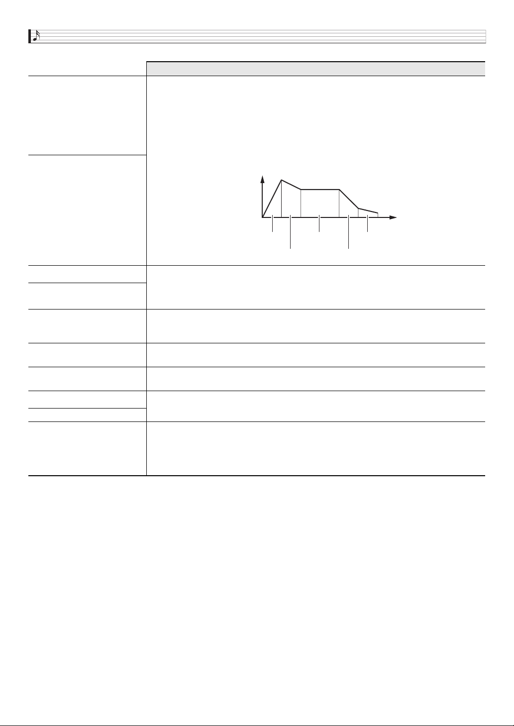
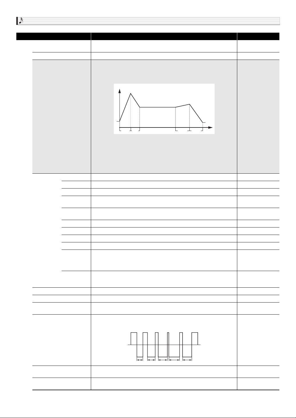
• Three EG (envelope generators):
Control changes in pitch, timbre, volume, and other parameters over time.
The nearby illustration shows an example of a volume envelope.
(2) Synthesizer OSC2 Block
(3) PCM OSC1 Block
This block creates sound based on PCM sounds (same sound quality as sounds in the PCM
Tone category). For information about how the editable parameters of this block differ from
those for the OSC blocks above, see “Editable Parameters of Blocks (1) through (6)” (page
E-23).
(4) PCM OSC2 Block
(5) External Input Sound Block
Instead of an oscillator, this block creates sound based on sound input through the
Synthesizer’s
cl
MIC IN and INST IN jacks. The pitch change range of sound produced by
this block is limited.
(6) Noise Block
Instead of an oscillator, this block creates sound based on noise generated by a special noise
generator. The pitch of sound produced by this block cannot be edited.
(7) Total Block
This block combines signals (1) through (6) and sends the completed tone to the filters and
DSP (a type of effect).
(8) LFO1 Block
“LFO” is an abbreviation of “low-frequency oscillator”. The LFOs send waveform information to
each block that is used as the basis for modulation, tremolo and other reverb effects.
(9) LFO2 Block
(10) Controllers
Controllers include the keyboard, bender, and other controllers, as well as MIDI messages.
Control messages are sent to blocks (1) through (9) to control tones.
A virtual controller function can be used to freely configure combinations of controller types
(sources) and the parameters being controlled (destinations) to perform such actions as “pedal
depressed, change volume”.
Volume
Time
Attack Sustain Release 2
Decay Release 1
Selecting and Creating Tones
E-23
■ Editable Parameters of Blocks (1) through (6)
•The nine sliders (
5
) and four knobs (
3
) can be used for quick and easy adjustment of some of the parameters in the list
below (page
E-34).
Preparation
Perform the following steps from the screen in step 2 of the procedure under “To edit and save a tone as a user tone” on page
E-20.
1.
Select “OSC Block >Ent” and then press
br
ENTER to enter the group.
2.
Use the
9
PART minus (–) and plus (+) buttons to select the block you want to edit.
Editable Parameter List
• Shaded cells indicate a group made up of multiple items. Press
br
ENTER to display the items that make up a group.
• (V) at the end of a display item indicates an item that can be selected as a Block (10) virtual controller destination (page E-29).
Display Text Description Settings
OSC On Off OSC on/off. Selecting off disables the entire block. Off, On
Oscillator >Ent (Block (1) to (5) only)
Oscillator. Group of editable parameters associated with the pitch of the synth
OSC, PCM OSC, and pitch shift.
• This group can be entered by performing step 1 under “To edit and save a tone
as a user tone” (page E-20) and then holding down
7
EDIT.
Synth Wave
(Blocks (1) and (2) only)
PCM Wave
(Blocks (3) and (4) only)
Synth wave, PCM wave. Selects the base wave for a sound generated by the
synth OSC or PCM OSC.
• A wave whose name is displayed with “L” or “B” next to it will sound at a pitch
that is one octave lower than the actual pitch. In the case of a “B” wave, nothing
will sound when a keyboard key higher than C5 is pressed.
• See the separate “Appendix” for details about wave types.
• This item is not present in Block (5).
• The splits of a user wave tone (User Wave) can be assigned as PCM waves.
User wave names consist of the text “UserWave”, followed by two number
separated by a hyphen (such as: UserWave 1-2). The number to the left of the
hyphen (1 in the example), is a user number from 1 to 10 or the letter R
(sample looper recorded data). The number to the right of the hyphen (2 in the
example), is a split number from 1 to 5. If the data includes a wave, an asterisk
(*) is appended to the beginning of the user wave name.
See the separate
“Appendix”.
Pitch (V)
Pitch. Adjusts the maximum and minimum pitch values within a range of ±2
octaves. A setting of –256 lowers the pitch two octaves, while a setting of 255
raises the pitch two octaves.
–256 to 0 to +255
Detune (V) Detune. Fine adjustment of the tuning. –256 to 0 to +255
KeyFollow (V)
Key follow. Adjusts the amount of pitch change between neighboring keyboard
keys. A higher value represents greater change.
Example: When Key Follow Base is keyboard key C4
–128 to 0 to +127
Block
Syn1: Synth OSC1
Syn2: Synth OSC2
PCM1: PCM OSC1
PCM2: PCM OSC2
Ext: External input
Noise: Noise
D
4
C
#
4
C
4
C
4
Key Follow = 127
Key Follow = 64
Key Follow = 0
Key Follow = -127
C
#
4
B
b
4
Key Follow
Key Follow Base
Selecting and Creating Tones
E-24
KeyFolBase (V)
Key follow base. Keyboard key that is the center of key follow.
• Setting value can be specified using the keyboard keys.
C- to G9*
Env.Depth (V) Envelope depth. Specifies how the envelope shown below is applied. –64 to 0 to +63
Envelope >Ent
Pitch envelope. Group of editable parameters for envelope (Envelope Generator)
applied to the synth OSC, PCM OSC, and pitch shifter.
• The figure below also applies to filter, amp, and other envelopes. With the pitch
envelope, the pitch of the sound corresponds to the vertical (Level) axis.
Init.Level (V) Initial level. Pitch of the sound at initial note on. –64 to 0 to +63
Atk.Time (V) Attack time. Time it takes until the attack level is reached from the initial level. 0 to 127
Atk.Level (V) Attack level. Target level reached immediately after note on. –64 to 0 to +63
Dcy.Time (V)
Decay time. Time it takes for the sound to reach the sustain level from the attack
level.
0 to 127
Sus.Level (V)
Sustain level. Level the sound is sustained as long as a key or pedal is
depressed.
–64 to 0 to +63
Rel.Time1 (V) Release time 1. Time it takes to reach Release Level 1 after a key is released. 0 to 127
Rel.Level1 (V) Release level 1. Target level reached immediately after a key is released. –64 to 0 to +63
Rel.Time2 (V) Release time 2. Time it takes to reach Release Level 2 from Release Level 1. 0 to 127
Rel.Level2 (V) Release level 2. Second target level reached after a key is released. –64 to 0 to +63
Clk.Trig
Clock trigger. Specifies the number of beats for resetting the envelope. Selecting
a setting from 1/4U to 4U resets to the timing of the up beat.
Off, 1/4, 1/3, 1/2, 2/3,
1, 3/2, 2, 3, 4, 1/4U,
1/3U, 1/2U, 2/3U, 1U,
3/2U, 2U, 3U, 4U
Ext.Trig
(Block (5)
only)
External trigger. When on, the envelope is reset by an external trigger. Off, On
LFO1 Depth (V) LFO1 depth. Specifies how LFO1 from Block (8) is applied. –64 to 0 to +63
LFO2 Depth (V) LFO2 depth. Specifies how LFO2 from Block (9) is applied. –64 to 0 to +63
PulseWidth
(Blocks (1) and (2) only) (V)
Pulse width. Adjusts the width of the square wave when the synth wave is a
square wave.
0 to 127
PWM LFO1 Dep
(Blocks (1) and (2) only) (V)
PWM LFO1 depth. Adjusts the depth of pulse width modulation by LFO1.
–64 to 0 to +63
PWM LFO2 Dep
(Blocks (1) and (2) only) (V)
PWM LFO2 depth. Adjusts the depth of pulse width modulation by LFO2. –64 to 0 to +63
Sync OSC (Block (2) only)
Oscillator sync. Turning on this resets the Block (2) sound wave in accordance
with the Block (1) sound wave period, cause them to become synced.
Off, On
Display Text Description Settings
IL
AL
SL
RL1
RL2
AT DT RT1 RT2
Level
Time
IL : Init Level RT1 : Release Time1
AT : Attack Time RL1 : Release Level1
AL : Attack Level RT2 : Release Time2
DT : Decay Time RL2 : Release Level2
SL : Sustain Level
PWM
Selecting and Creating Tones
E-25
OriginalKey (Block (5) only)(V)
Original key. Selects the keyboard keys where the externally input sound to
Block (5) is sounded as-is at its original pitch.
• Setting can be specified using the keyboard keys.
C- to G9*
MicInstLvl (Block (5) only) (V) Mic/inst level. Level of external input sound to Block (5). 0 to 127
TrigThresh (Block (5) only) (V)
Trigger threshold. Specifies the external input level threshold value that
determines whether or not an external input trigger (page E-24) is applied.
0 to 127
TrigRelease
(Block (5) only) (V)
Trigger release time. Adjusts the time following external input trigger (page E-24)
operation that the next trigger operation is blocked.
0 to 127
P.ShiftMode (Block (5) only)
Pitch shifter mode. A larger setting value lengthens the time until note on, but
increases tone quality. When this setting is off, the same pitch sounds no matter
which keyboard key is pressed.
Off, 1, 2, 3
P.ShiftMix (Block (5) only)
Pitch shifter mix. Specifies the volume ratio between the pitch shifted sound (shift
sound) and the unshifted sound.
0: Shift sound only
7: Both sounds at same volume
15: Original sound only
0 to 15
Noise Type (Block (6) only)
Noise type. Selects the type of noise generated by Block (6). White noise (equal
noise for all frequencies), pink noise (noise inversely proportional to the
frequency) and other types of noise are available.
• See the separate “Appendix” for a complete list of noise types.
See the separate
“Appendix”.
Filter >Ent
Filter. Group of editable parameters associated with the filters (tones) in each
block.
Gain
Gain. Specifies how the volume of frequency components that are higher than
the cut off frequency setting value described below is attenuated. There is no cut
off when “Flat” is specified here.
–18dB, –12dB, –6dB,
–3dB, Flat
Cutoff (V) Cutoff frequency. Specifies the filter cutoff frequency. 0 to 15
TouchSense (V)
Touch sense. Specifies the degree of change in the filter in accordance with
change in keyboard playing touch.
–64 to 0 to +63
KeyFollow (V)
Key follow. Adjusts the amount of filter change between neighboring keyboard
keys. A higher value represents greater change.
–128 to 0 to +127
KeyFolBase (V)
Key follow base. Keyboard key that is the center of key follow.
• Setting can be specified using the keyboard keys.
C- to G9*
Env.Depth (V) Envelope depth. Specifies how the envelope shown below is applied. –64 to 0 to +63
Envelope >Ent
Filter envelope. Group of editable parameters for envelope (Envelope Generator)
applied to filters.
• For details about group items and setting ranges, see “Pitch Envelope”. With
this group, the vertical (Level) axis in the pitch envelope diagram corresponds
to how the filter is applied.
0 to 127 (Initial Level
to Release Level 2)
• The setting ranges
for Clock Trigger
and External Input
Trigger are the
same as those for
Pitch Envelope.
LFO1 Depth (V) LFO1 depth. Specifies how LFO1 from Block (8) is applied. –64 to 0 to +63
LFO2 Depth (V) LFO2 depth. Specifies how LFO2 from Block (9) is applied. –64 to 0 to +63
Amp >Ent
Amp. Group of editable parameters associated with the amp (volume) in each
block.
Volume (V) Volume. Specifies the amp volume. 0 to 127
TouchSense (V)
Touch sense. Specifies the degree of change in volume in accordance with
change in keyboard playing touch.
–64 to 0 to +63
KeyFollow (V)
Key follow. Adjusts the amount of volume change between neighboring keyboard
keys. A higher value represents greater change.
–128 to 0 to +127
KeyFolBase (V)
Key follow base. Keyboard key that is the center of key follow.
• Setting can be specified using the keyboard keys.
C- to G9*
Envelope >Ent
Amp envelope. Group of editable parameters for envelope (Envelope Generator)
applied to amps.
• For details about group items, see “Pitch Envelope”. The vertical (Level) axis in
the pitch envelope diagram corresponds to the volume in the case of this
group. However, the setting range for the nine items from Initial Level to
Release Level 2 is 0 to 127, which is different from the pitch envelope items.
0 to 127 (Initial Level
to Release Level 2)
• The setting ranges
for Clock Trigger
and External Input
Trigger are the
same as those for
Pitch Envelope.
LFO1 Depth (V) LFO1 depth. Specifies how LFO1 from Block (8) is applied. –64 to 0 to +63
LFO2 Depth (V) LFO2 depth. Specifies how LFO2 from Block (9) is applied. –64 to 0 to +63
Display Text Description Settings

Selecting and Creating Tones
E-26
* “C-” on the display indicates C-1 (one octave below C0).
Legato
Legato. Turning this setting on causes subsequent notes to be played smoothly
and connected.
Off, On
Portamento
Portamento. Turning on this setting applies a portamento effect.
• This item is not present in Block (6).
Off, On
PortaTime (V)
Portamento Time. Specifies the time until the next note is reached by
Portamento.
• This item is not present in Block (6).
0 to 127
Display Text Description Settings
Selecting and Creating Tones
E-27
■ Block (7): Total Block Filter Editable Parameters
Preparation
On the screen that appears in step 2 under “To edit and save a tone as a user tone” (page E-20), select “Total Filter >Ent” and then
press
br
ENTER to enter the group.
Editable Parameter List
• Shaded cells indicate a group made up of multiple items. Press
br
ENTER to display the items that make up a group.
• (V) at the end of a display item indicates an item that can be selected as a Block (10) virtual controller destination (page E-29).
* “C-” on the display indicates C-1 (one octave below C0).
Display Text Description Settings
FilterType
Filter type. Selects the filter type.
LPF: Low-pass filter. Cuts high-range components above the cut off frequency.
BPF: Band-pass filter. Cuts low-range and high-range components outside of a range centered on
the cut off frequency.
HPF: High-pass filter. Cuts low-range components below the cut off frequency.
Refer to the cell to the
left.
Cutoff (V) Cutoff frequency. Specifies the cut off frequency of all Solo Synthesizer tones. 0 to 127
Resonance (V) Resonance. Emphasizes notes in the vicinity of the cut off frequency to alter the tone. 0 to 127
TouchSense (V)
Touch sense. Specifies the degree of change in the filter in accordance with change in keyboard
playing touch.
–64 to 0 to +63
KeyFollow (V)
Key follow. Adjusts the amount of filter change between neighboring keyboard keys. A higher value
represents greater change.
–128 to 0 to +127
KeyFolBase (V)
Key follow base. Keyboard key that is the center of key follow.
• Setting can be specified using the keyboard keys.
C- to G9*
Env.Retrig
Envelope generator retrigger. Turning on this setting retriggers the filter with each keyboard key
press.
Off, On
Env.Depth (V) Envelope depth. Specifies how the envelope shown below is applied. –64 to 0 to +63
Envelope >Ent
Total filter envelope. Group of editable parameters for envelope (Envelope Generator) applied to
Total Block filters.
• For details about group items, see “Pitch Envelope”. With this group, the vertical (Level) axis in the
pitch envelope diagram corresponds to how the filter is applied.
0 to 127 (Initial Level to
Release Level 2)
• The setting ranges for
Clock Trigger and
External Input Trigger
are the same as those
for Pitch Envelope.
LFO1 Depth (V) LFO1 depth. Specifies how LFO1 from Block (8) is applied. –64 to 0 to +63
LFO2 Depth (V) LFO2 depth. Specifies how LFO2 from Block (9) is applied. –64 to 0 to +63
Selecting and Creating Tones
E-28
■ Block (8): LFO1 and Block (9): LFO2 Editable Parameters
Preparation
Perform the following steps from the screen in step 2 of the procedure under “To edit and save a tone as a user tone” on page
E-20.
1.
Select “LFO >Ent” and then press
br
ENTER to enter the group.
2.
Use the
9
PART minus (–) and plus (+) buttons to select the block you want to edit.
Editable Parameter List
• (V) at the end of a display item indicates an item that can be selected as a Block (10) virtual controller destination (page E-29).
Display Text Description Settings
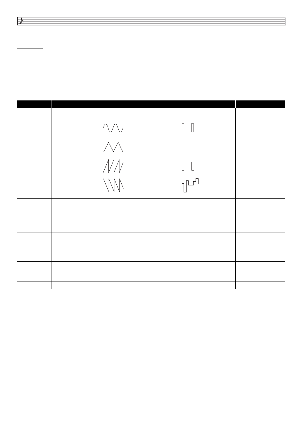
WaveType
Wave type. Specifies one of the following wave types to be used for LFO.
Refer to the cell to the
left.
Sync
Sync. Specifies what LFO is synced with.
Off: No syncing
Tempo: Synced with beat specified by clock sync (see below).
LFO1 (Can be selected with LFO2 only.): Synced with LFO1.
Refer to the cell to the
left.
Rate (V)
Rate. Specifies the LFO speed (frequency). This setting is enabled when the above Sync setting is
off.
0 to 127
Clk.Sync
Clock sync. Specifies the number of beats synced with the LFO frequency. Selecting a setting from
1/4U to 4U syncs with the timing of the up beat.
• This setting a valid only when the sync setting is “Tempo”.
1/4, 1/3, 1/2, 2/3, 1, 3/2,
2, 3, 4, 1/4U, 1/3U, 1/2U,
2/3U, 1U, 3/2U, 2U, 3U,
4U
Depth (V) Depth. Specifies how LFO is applied. 0 to 127
Delay (V) Delay. Specifies the degree of delay in the timing for applying LFO. 0 to 127
Rise (V)
Rise. Specifies the time it takes from the start of application of the LFO until the effect reaches the
level specified by Depth above.
0 to 127
Mod.Depth (V) Modulation depth. Specifies how modulation is applied to the LFO. 0 to 127
Sin
(Sine Wave)
Puls 1:3
(Square Wave 1:3)
Tri
(Triangular Wave)
Puls 2:2
(Square Wave 2:2)
Saw up
(Sawtooth Wave Up)
Puls 3:1
(Square Wave 3:1)
Saw down
(Sawtooth Wave
Down)
Random
(Random)
Selecting and Creating Tones
E-29
■ Block (10): Controllers Editable Parameters for Virtual Controller
These controllers are virtual controllers for adjusting any editable parameters (destinations) with any input method (source).
Preparation
Perform the following steps from the screen in step 2 of the procedure under “To edit and save a tone as a user tone” on page
E-20.
1.
Select “VirtualCtrl >Ent” and then press
br
ENTER to enter the group.
• Controllers are numbered 1 through 8, and are assigned to the
5
sliders (1/9 through 8/16).
2.
Use the
9
PART minus (–) and plus (+) buttons to select the number of the controller you want to edit.
Editable Parameter List
■ Other Editable Items
This section explains parameters that are not part of the blocks described up to this point. These settings not only apply to the Solo
Synthesizer, but also to other category tones as well.
Preparation
Display the screen in step 2 of the procedure under “To edit and save a tone as a user tone” on page E-20.
Editable Parameter List
• Shaded cells indicate a group made up of multiple items. Press
br
ENTER to display the items that make up a group.
Display Text Description Settings
Source
Source. Specifies the input method.
Off: None
CC00 to CC97: MIDI control change*
NoteOnKeyNum: Key number of MIDI note on message
NoteOnVel: Velocity value of MIDI note on message
Ch.Pressure: MIDI channel after touch
Bend Up: Upward operation from
bt
BENDER center
Bend Down: Downward operation from
bt
BENDER center
Modulation:
bt
MODULATION operation
LFO1: LFO1 (Block (8))
LFO2: LFO2 (Block (9))
* For details about each setting, refer to the MIDI Implementation document
(http://world.casio.com/) and other MIDI documentation.
Refer to the cell to the
left.
Depth Depth. Specifies how virtual controller is applied. –128 to 0 to +127
Dest Destination. Specifies the destination parameter for a virtual controller operation.
•Off
• Block (1) to (9)
parameters (pages
E-23 through E-28)
whose “Display Text”
items have “(V)” after
them.
• DSP parameters (page
E-100)
Display Text Description Settings
DSP On/Off
(Non-Solo
Synthesizer
tones only)
DSP on/off. Specifies whether or not DSP should be applied to tones.
• When this setting is on, pressing
br
ENTER enters the DSP editing screen (page E-39).
• This item is not displayed on the Solo Synthesizer tone editing list.
Off, On
DSP Edit >Ent
DSP edit. Group of editable effect function DSPs (page E-36). Press
br
ENTER to advance to the
DSP editing screen.
Disabled when the above DSP On/Off setting is off.
Volume Volume. Specifies the main volume. 0 to 127
Rev.Send Reverb send. Specifies how reverb (page E-36) is applied to a tone. 0 to 127
Cho.Send
(Non-Solo
Synthesizer
tones only)
Chorus send. Specifies how chorus (page E-36) is applied to a tone.
• This item is not displayed on the Solo Synthesizer tone editing list.
0 to 127
Selecting and Creating Tones
E-30
There are two types of parameters: PCM melody tone specific editable parameters and the same parameters that apply to the
other tone categories.
The drum sets in the PCM tones have different editable parameters. See “Editable Parameters for Drum PCM Tone” for more
information about them.
■ Editable Parameters for Non-drum Set PCM Tone
Preparation
Display the screen in step 2 of the procedure under “To edit and save a tone as a user tone” on page E-20.
Editable Parameter List
■ Editable Parameters Common to Other Tone Categories
See “Other Editable Items” on page E-29.
Editable Parameters for PCM Melody Tone (Non-drum PCM Tones)
Display Text Description Settings
Atk.Time Attack time. Specifies the time it takes to reach peak value from note on. –64 to 0 to +63
Rel.Time Release time. Specifies the time it takes for a sustained sound to decay after a key is released. –64 to 0 to +63
Cutoff Cutoff frequency. Specifies the tone cutoff frequency. –64 to 0 to +63
Vib.Type
Vibrato type. Specifies one of the wave types below to be used for vibrato.
Sin (sine wave), Tri (triangular wave), Saw (sawtooth wave), Sqr (square wave)
Sin, Tri, Saw, Sqr
Vib.Depth Vibrato depth. Specifies how vibrato is applied. –64 to 0 to +63
Vib.Rate Vibrato rate. Specifies the vibrato rate (frequency). –64 to 0 to +63
Vib.Delay Vibrato delay. Specifies the delay in the timing for applying vibrato. –64 to 0 to +63
Oct.Shift Octave shift. Changes the tone of notes in octave units. –2 to 0 to +2
TouchSense
Touch sense. Specifies the degree of change in volume in accordance with change in keyboard
playing touch.
–64 to 0 to +63
Selecting and Creating Tones
E-31
The editable parameters described here are for the drum set tones. There are two types of parameters: PCM drum tone specific
editable parameters and the same parameters that apply to the other tone categories.
■ Editable Parameters for Drum Set PCM Tone
Preparation
Display the screen in step 2 of the procedure under “To edit and save a tone as a user tone” on page E-20.
Editable Parameter List
• Shaded cells indicate a group made up of multiple items. Press
br
ENTER to display the items that make up a group.
Editable Parameters for Drum PCM Tone
Display Text Description Settings
Inst Edit >Ent
Instrument edit. Group of editable parameters for drum tone for each
keyboard.
• Press a keyboard key to specify the keyboard to be edited.
• This group can be entered by performing step 1 under “To edit and save
a tone as a user tone” (page E-20) and then holding down
7
EDIT.
(C- to G9*)
Inst Select >Ent
Instrument select. Group of editable parameters for tone. Keyboard key
pressure (Velocity) is divided into four velocity ranges. Each range can be
configured to sound a different tone (Inst Number).
•Use the
9
PART minus (–) and plus (+) buttons to select the range
you want to edit.
Inst Number
Instrument number. Selects the drum tone wave assigned to each
velocity range.
• See the separate “Appendix” for details about wave types.
• The splits of a user wave tone (User Wave) can be assigned as Inst
Numbrers. User wave names consist of the text “UserWave”, followed
by two number separated by a hyphen (such as: UserWave 1-2). The
number to the left of the hyphen (1 in the example), is a user number
from 1 to 10 or the letter R (sample looper recorded data). The number
to the right of the hyphen (2 in the example) a split number from 1 to 5.
If the data includes a wave, an asterisk (*) is appended to the beginning
of the user wave name.
See the separate
“Appendix”.
VelRangeHi Velocity range high. Determines the high limit of each velocity range. 0 to 127
Volume Volume. Specifies drum sound volume. –128 to 0 to +127
Pan Pan. Specifies the stereo position of drum sound. –64 to 0 to +63
Rev.Send Reverb send. Specifies how reverb is applied to a drum tone. 0 to 127
NoteOffMode
Note off mode. Turning on this setting causes note off to be performed
when a key is released.
Off, On
Assign Grp
Assign group. Specifies as a value from 1 to 15 which group the currently
selected keyboard should be placed into. Only one keyboard in a group is
sounded at any time (non-polyphonic).
Off, 1 to 15
Pitch LFO >Ent Pitch LFO. Group of editable LFOs applied to pitch.
WaveType
Wave type. Specifies a wave type to be used for LFO. The details of the
selectable waves are the same as those for “WaveType” of “Block (8):
LFO1 and Block (9): LFO2 Editable Parameters” (page E-28).
Sin, Tri, SawUp,
SawDown, Puls1:3,
Puls2:2, Puls3:1
Rate Rate. Specifies the LFO speed (frequency). 0 to 127
Depth Depth. Specifies how LFO is applied. –128 to 0 to +127
Delay Delay. Specifies the degree of delay in the timing for applying LFO. 0 to 127
Rise
Rise. Specifies the time it takes from the start of application of the LFO
until the effect reaches the level specified by Depth above.
0 to 127
Mod.Depth Modulation depth. Specifies how modulation is applied to the LFO. 0 to 127
After Depth
After depth. Specifies LFO change when MIDI channel after touch is
received.
0 to 127
Inst Number
[1] [2] [3] [4]
Cannot be
specified.
range 1 range 2 range 3 range 4
0
Velocity Range Hi
[1] [2] [3] [4] 127 Velocity
Selecting and Creating Tones
E-32
* “C-” on the display indicates C-1 (one octave below C0).
■ Editable Parameters Common to Other Tone Categories
For information about Solo Synthesizer tones, see “Other Editable Items” on page E-29.
There are two types of editable parameters for user wave tone: editable parameters that are specific to the User Wave Tone
category and the parameters that also apply to the other tone categories.
■ User Wave Tone Category Specific Tone Parameters
Preparation
Display the screen in step 2 of the procedure under “To edit and save a tone as a user tone” on page E-20.
Editable Parameter List
•
Shaded cells indicate a group made up of multiple items. Press
br
ENTER to display the items that make up a group.
Amp LFO >Ent
Amp LFO. Group of editable LFOs applied to volume. Items within a
group and setting ranges are the same as “LFO (Pitch LFO)”, above.
Refer to the cell to the
left.
Editable Parameters for User Wave Tone
Display Text Description Parameter
Split Edit >Ent
Split Edit. Group of editable parameters for splits recorded with the sample looper.
• Use the
9
PART minus (–) and plus (+) buttons to switch between splits.
Volume Volume. Specifies the volume. 0 to 127
Pan Pan. Specifies the stereo position of the sound. –64 to 0 to 63
CoarseTune Coarse tune. Changes the pitch of notes by semitone units. –24 to 0 to 24
Fine Tune
Fine tune. Fine tunes the pitch of the sound. Lowers the value up to –256 or raises the
value up to +255 in semitone steps.
–256 to 0 to 255
CutOff Cutoff frequency. Specifies the cut off frequency of a user wave tone. 0 to 127
TouchSense
Touch sense. Specifies the degree of change in volume in accordance with change in
keyboard playing touch.
–64 to 0 to 63
KeyFollow
Key follow. Adjusts the amount of pitch change between neighboring keyboard keys. A
higher value represents greater change.
–128 to 0 to 127
KeyFolBase
Key follow base. Keyboard key that is the center of key follow.
• Setting can be specified using the keyboard keys.
C- to G9*
P.Env.Depth Pitch envelope depth. Specifies how envelopes are applied to pitch. –64 to 0 to 63
Pitch Env >Ent
Pitch envelope. Group of editable parameters for envelope (Envelope Generator) applied
to pitch.
Init.Level Initial level. Pitch of the sound at initial note on. –64 to 0 to 63
Atk.Time Attack time. Time it takes until Level 0 is reached from the initial level. 0 to 127
Rel.Time Release time. Time it takes to reach Release Level after a key is released. 0 to 127
Rel.Level Release Level. Target level reached immediately after a key is released. –64 to 0 to 63
Amp Env >Ent
Amp envelope. Group of editable parameters for envelope (Envelope Generator) applied to
amps.
• For details about group items, see “Pitch Envelope” (page E-24). The vertical (Level) axis
in the pitch envelope diagram corresponds to the volume in the case of this group.
However, the setting range for the nine items from Initial Level to Release Level 2 is 0 to
127, which is different from the pitch envelope items. Note, however, that there is no
Clock Trigger item on the user tone “Amp Env >Ent” menu.
0 to 127 (Initial Level
to Release Level 2)
• The External Input
Trigger range is the
same as those for
“Pitch Envelope”.
KeyRangeLow
Key Range Low. Sets the low range of the effective keyboard for split playback.
• Setting can be specified using the keyboard keys.
C- to G9*
KeyRangeHi
Key Range High. Sets the high range of the effective keyboard for split playback.
• Setting can be specified using the keyboard keys.
C- to G9*
OriginalKey
Original key. Specifies the keyboard where the split plays as-is.
• Setting can be specified using the keyboard keys.
C- to G9*
Points >Ent Point. Changes the split start point, loop point, and end point positions.
Display Text Description Settings
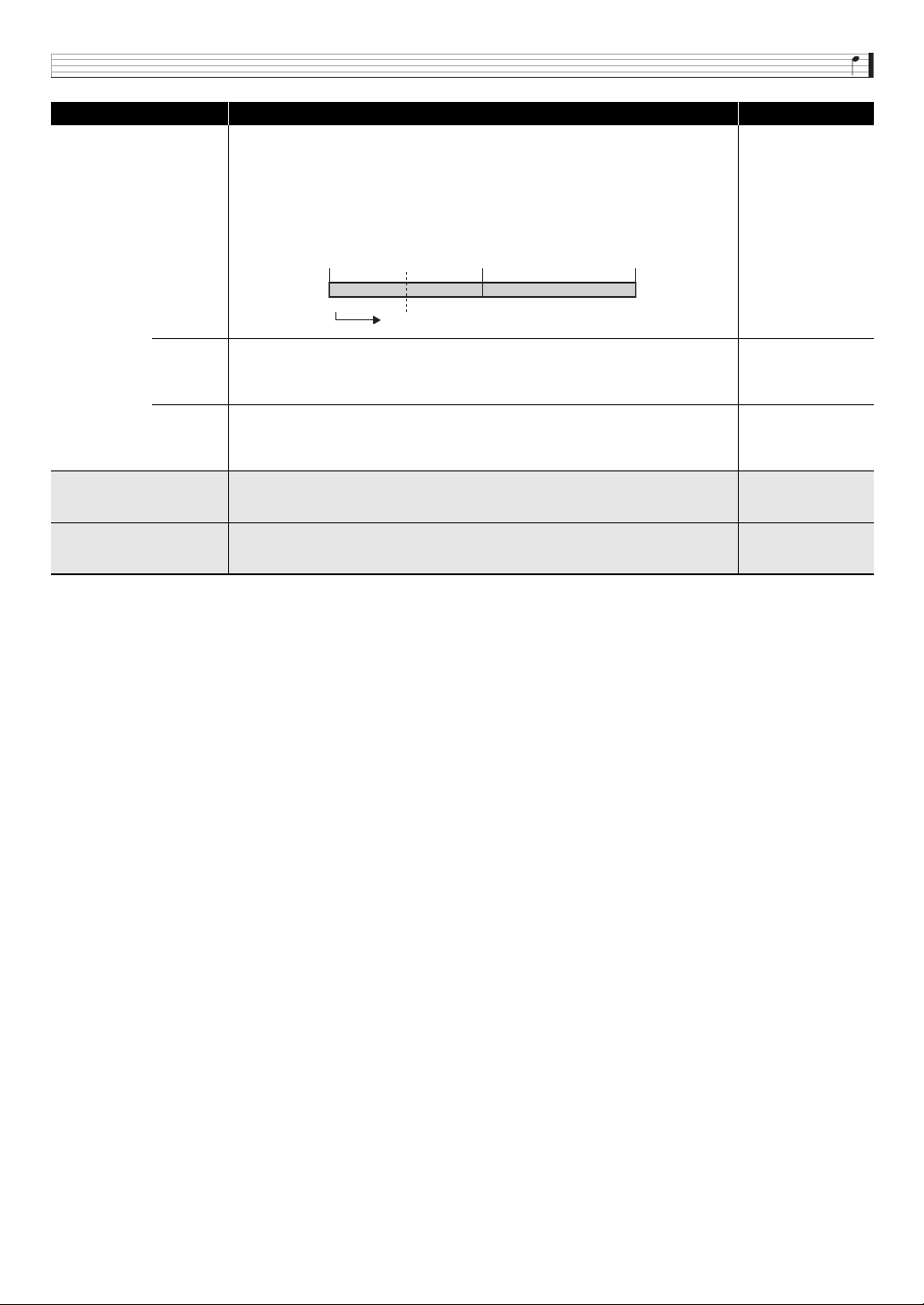
Selecting and Creating Tones
E-33
* “C-” on the display indicates C-1 (one octave below C0).
■ Editable Parameters Common to Other Tone Categories
For information about Solo Synthesizer tones, see “Other Editable Items” on page E-29.
Start
Start Point. The overall length of a split is recorded as values as shown in the illustration
below. You can change the start point of a split by changing its first number.
• You can input the split start point value using the
bq
number buttons (0 to 9).
• You can also use the
br
minus (–) and plus (+) buttons to change the leftmost three
digits of the value.
Example: Changing the first position number from 100000 to 125000 will move the start
point to a position later in the loop.
0 to 205000
(stereo recording),
0 to 410000
(monaural recording)
Loop
Loop Point. As with the Start Point, you can change the position of the loop point.
• You can input the split loop point value using the
bq
number buttons (0 to 9).
• You can also use the
br
minus (–) and plus (+) buttons to change the leftmost three
digits of the value.
0 to 205000
(stereo recording),
0 to 410000
(monaural recording)
End
End Point. As with the Start Point, you can change the position of the end point.
• You can input the split end point value using the
bq
number buttons (0 to 9).
• You can also use the
br
minus (–) and plus (+) buttons to change the leftmost three
digits of the value.
0 to 205000
(stereo recording),
0 to 410000
(monaural recording)
Pitch LFO >Ent
Pitch LFO. This is a group of editable parameters for LFOs applied to pitch. The settings
ranges of the parameters in this group are the same as for Pitch LFO of the “Editable
Parameters for Drum Set PCM Tone” (page E-31).
Refer to the cell to the
left.
Amp LFO >Ent
Amp LFO. This is a group of editable parameters for LFOs applied to volume. The settings
ranges of the parameters in this group are the same as for Amp LFO of the “Editable
Parameters for Drum Set PCM Tone” (page E-31).
Refer to the cell to the
left.
Display Text Description Parameter
Start Point Loop Point End Point
100000 150000 200000
125000
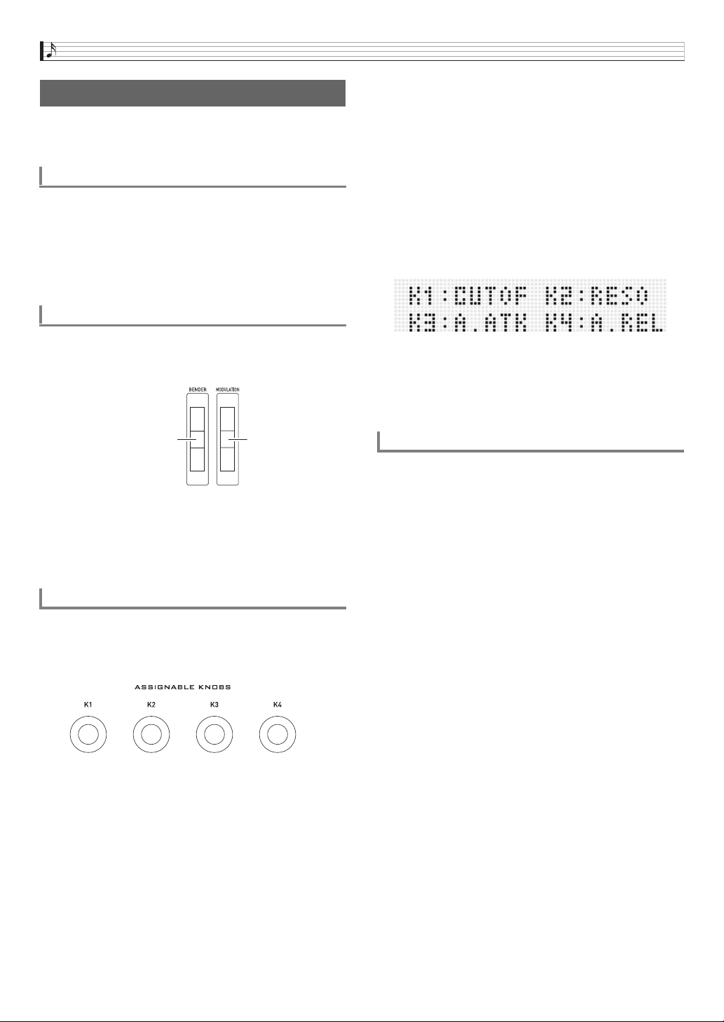
Selecting and Creating Tones
E-34
You can use a pedal, the bender, or other devices, to instantly
change the pitch and volume of notes, the envelope, and
other parameters as you perform.
A pedal operation can be used to sustain notes, arpeggios
(page E-40), or phrases (page E-45), or to apply a soft effect.
• For information about connecting a pedal, see page E-8.
• You can specify the effect applied by a pedal operation by
performing the following operation on the performance
editing list: Controller >Ent 3 Pedal. See page E-74 for
more information.
The
bt
BENDER wheel can be use to seamlessly raise or
lower the pitch of a sound, while the
bt
MODULATION wheel
adds vibrato (modulation effect) to the sound.
• Do not have a wheel rotated as you turn on Synthesizer
power.
• You can control the bend range of the
bt
BENDER wheel
by configuring the following settings on the performance
editing list: BendRngDwn, BendRngUp (page E-73).
The four
3
ASSIGNABLE KNOBS can be assigned
functions that enable instant adjustment of a sound attack
time and other envelope parameters (page E-21), volume,
and more.
• The following shows the knob functions for each Zone Part
1 tone category.
Solo Synthesizer tones (page E-23)
PCM melody tones (page E-30)
PCM drum tones (page E-31)
User Wave tones (page E-32)
The above functions show the abbreviated names used on
the tone mode screen.
• In the performance mode, you can change the operations
currently assigned to the assignable knobs by performing
the following operation on the performance editing list
(page E-74):
Controller >Ent 3 K1 to K4.
You can use the nine sliders (
5
) to make simple
adjustments to the Solo Synthesizer oscillator, envelope, and
total filer/LFO parameters.
1.
Select a Solo Synthesizer tone.
2.
Use the
1
buttons to assign oscillator (OSC
BLOCK), envelope (ENV GENERATOR) or total
filter/LFO (TOTAL FILTER/LFO) parameters to
the sliders.
3.
Use the three
2
buttons to perform one of the
operations described below.
Controlling Sounds
Using a Pedal
Using the Wheels (Bender, Modulation)
bt
Using the Assignable Knobs
3
K1 : Virtual Controller 1 (page E-29)
K2 : Virtual Controller 2 (page E-29)
K3 : Virtual Controller 3 (page E-29)
K4 : Virtual Controller 4 (page E-29)
K1 : Cut off Frequency
K2 : Attack Time
K3 : Release Time
K4 : Reverb Send (Same as other tone categories.)
Raises and lowers pitch.
(Releasing wheel returns
to original pitch.)
Applies modulation.
(Raising wheel
applies modulation.)
K1 : Volume (Drum Inst >)
K2 : Pan (Drum Inst >)
K3 : Reverb Send (Drum Inst >)
K4 : Reverb Send (Same as other tone categories.)
K1 : Cut off Frequency
K2 : Attack Time (Amp Envelope >)
K3 : Release Time (Amp Envelope >)
K4 : Reverb Send (Same as other tone categories.)
Using Sliders
Y If you selected OSC BLOCK (oscillator) in step 2
Press
2
SELECT OSC to cycle through the OSC
blocks (1 through 6) and “ALL” (all OSC blocks), and
select the one you want.
Y If you selected ENV GENERATOR (envelope) in step 2
• Press
2
SELECT OSC to cycle through the OSC
blocks (1 through 6) and “ALL” (all OSC blocks), and
select the one you want.
• Press
2
SELECT EG to cycle through the EG
blocks (OSC, Filter, Amp, “ALL” (all EG blocks)) and
select the one you want.
Y If you selected TOTAL FILTER/LFO (total filter/LFO) in
step 2
Press
2
SELECT LFO to toggle between LFO1,
LFO2, and “ALL” (LFO1 and LFO2).
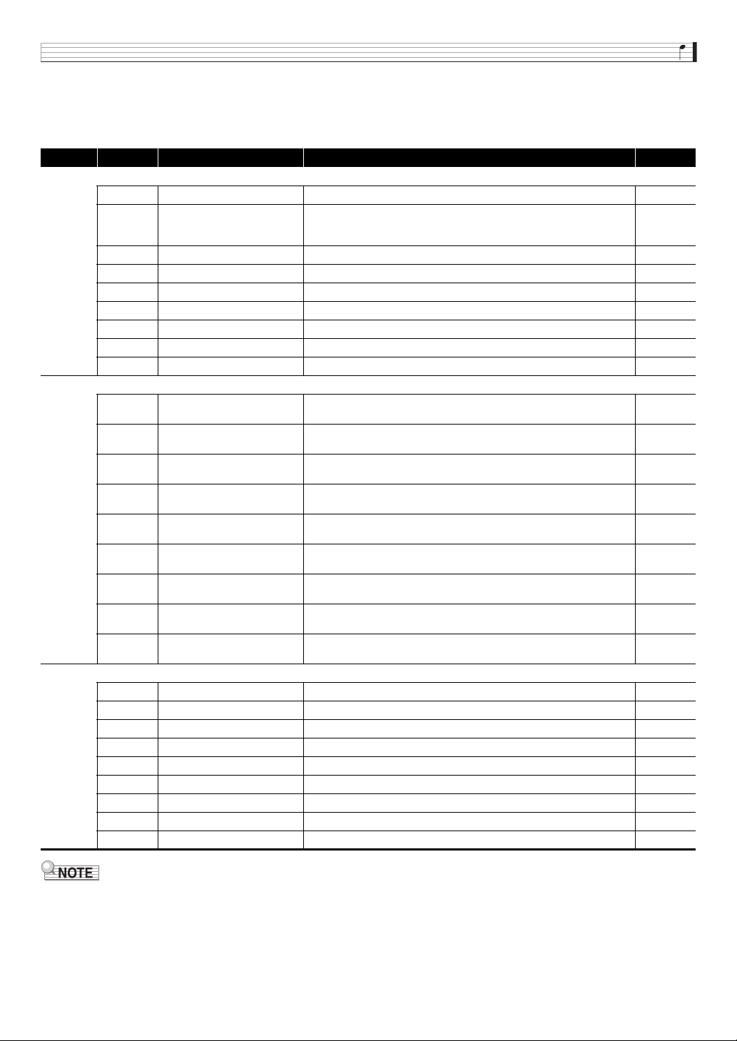
Selecting and Creating Tones
E-35
4.
Move the sliders (
5
) to adjust the parameters currently assigned to them.
• Refer to the table below for information about the parameters assigned to the sliders. For detailed information about each
parameter, see the reference pages included in the table.
• In the Performance Mode or Step Sequencer Mode, you can use the
1
buttons to edit tones with the sliders without changing
to another mode.
• PCM tones and user wave tones cannot be adjusted using the sliders.
• For more information about slider functions, see page E-52 for the Step Sequencer Mode and page E-78 for the Mixer Mode.
1
button
5
(Slider) Display Text Parameter See page:
OSC BLOCK
1/9 OSC ON/OFF OSC Block > OSC On/Off E-23
2/10 WAVE
OSC Block > Oscillator > Wave (Disabled for Ext OSC.)
• See the separate “Appendix” for the types of waves that can be
selected using the sliders.
E-23
3/11 PITCH OSC Block > Oscillator > Pitch (Disabled for Noise OSC.) E-23
4/12 DETUNE OSC Block > Oscillator > Detune (Disabled for Noise OSC.) E-23
5/13 PORTA TIME OSC Block > PortaTime E-26
6/14 P.ENV DEPTH OSC Block > Oscillator > Env.Depth (Disabled for Noise OSC.) E-24
7/15 CUTOFF OSC Block > Filter > CutOff E-25
8/16 F.ENV DEPTH OSC Block > Filter > Env.Depth E-25
MASTER VOLUME OSC Block > Amp > Volume E-25
ENV GENERATOR
1/9 INIT LEVEL
• OSC Block > Oscillator/Filter/Amp > Envelope > Init.Level
• TotalFilter > Envelope > Init.Level
E-24
2/10 ATK TIME
• OSC Block > Oscillator/Filter/Amp > Envelope > Atk.Time
• TotalFilter > Envelope > Atk.Time
E-24
3/11 ATK LEVEL
• OSC Block > Oscillator/Filter/Amp > Envelope > Atk.Level
• TotalFilter > Envelope > Atk.Level
E-24
4/12 DCY TIME
• OSC Block > Oscillator/Filter/Amp > Envelope > Dcy.Time
• TotalFilter > Envelope > Dcy.Time
E-24
5/13 SUS LEVEL
• OSC Block > Oscillator/Filter/Amp > Envelope > Sus.Level
• TotalFilter > Envelope > Sus.Level
E-24
6/14 REL TIME1
• OSC Block > Oscillator/Filter/Amp > Envelope > Rel.Time1
• TotalFilter > Envelope > Rel.Time1
E-24
7/15 REL LEVEL1
• OSC Block > Oscillator/Filter/Amp > Envelope > Rel.Level1
• TotalFilter > Envelope > Rel.Level1
E-24
8/16 REL TIME2
• OSC Block > Oscillator/Filter/Amp > Envelope > Rel.Time2
• TotalFilter > Envelope > Rel.Time2
E-24
MASTER REL LEVEL2
• OSC Block > Oscillator/Filter/Amp > Envelope > Rel.Level2
• TotalFilter > Envelope > Rel.Level2
E-24
TOTAL FILTER/LFO
1/9 TOTAL FILTER TYPE TotalFilter > FilterType E-27
2/10 TOTAL FILTER CUTOFF TotalFilter > CutOff E-27
3/11 TOTAL FILTER RESONANCE TotalFilter > Resonance E-27
4/12 TOTAL FILTER ENV.DEPTH TotalFilter > Env.Depth E-27
5/13 LFO WAVE LFO > WaveType E-28
6/14 LFO RATE LFO > Rate (Enabled only for Sync Off.) E-28
7/15 LFO DEPTH LFO > Depth E-28
8/16 LFO DELAY LFO > Delay E-28
MASTER LFO RISE LFO > Rise E-28
Selecting and Creating Tones
E-36
When the
bn
HOLD button is lit (by pressing it), the currently
sounding note or arpeggio (page E-40) will be sustained.
• Pressing
bn
HOLD again will cause its light to go out,
indicating that hold is turned off.
You can use the
bs
TRANSPOSE and OCTAVE (–, +)
buttons to change the pitch of the keyboard notes in
semitone or octave steps.
• For information about fine tuning the pitch in hertz steps
(Tuning), see page E-81.
1.
To change the pitch in semitone steps, hold
down
bs
TRANSPOSE as you press the
bs
OCTAVE minus (–) or plus (+) button.
• The setting range for this operation is one octave
upwards and downwards (–12 semitones to +12
semitones).
2.
To change the pitch in octave steps, use the
bs
OCTAVE minus (–) and plus (+) buttons
(without holding down
bs
TRANSPOSE).
• The setting range for this operation is three octaves
upwards and downwards (–3 octaves to +3 octaves).
• While the setting screen shown above is displayed you can
the
bp
dial or the
br
minus (–) or plus (+) buttons to
change the setting. If you do not perform any operation for
a while, the setting screen will be exited automatically.
You can apply reverb, vibrato, and other effects to notes to
enhance their sound.
■ Effect Block Diagram
Using the Hold Button
bn
Changing the Pitch of Notes in Semitone
Steps (Transpose) or Octave Steps (Octave
Shift)
bs
Lights when HOLD is on.
bs
Applying Effects to Notes
Sound
Source
(5) Master
Equalizer
Goes through (2), (3),
or (4). Also refer to
the “Chorus and DSP
Use Restrictions”
below.
Output
(1) Reverb
(2) Chorus
(3) Normal DSP
(4) Solo
Synthesizer
DSP
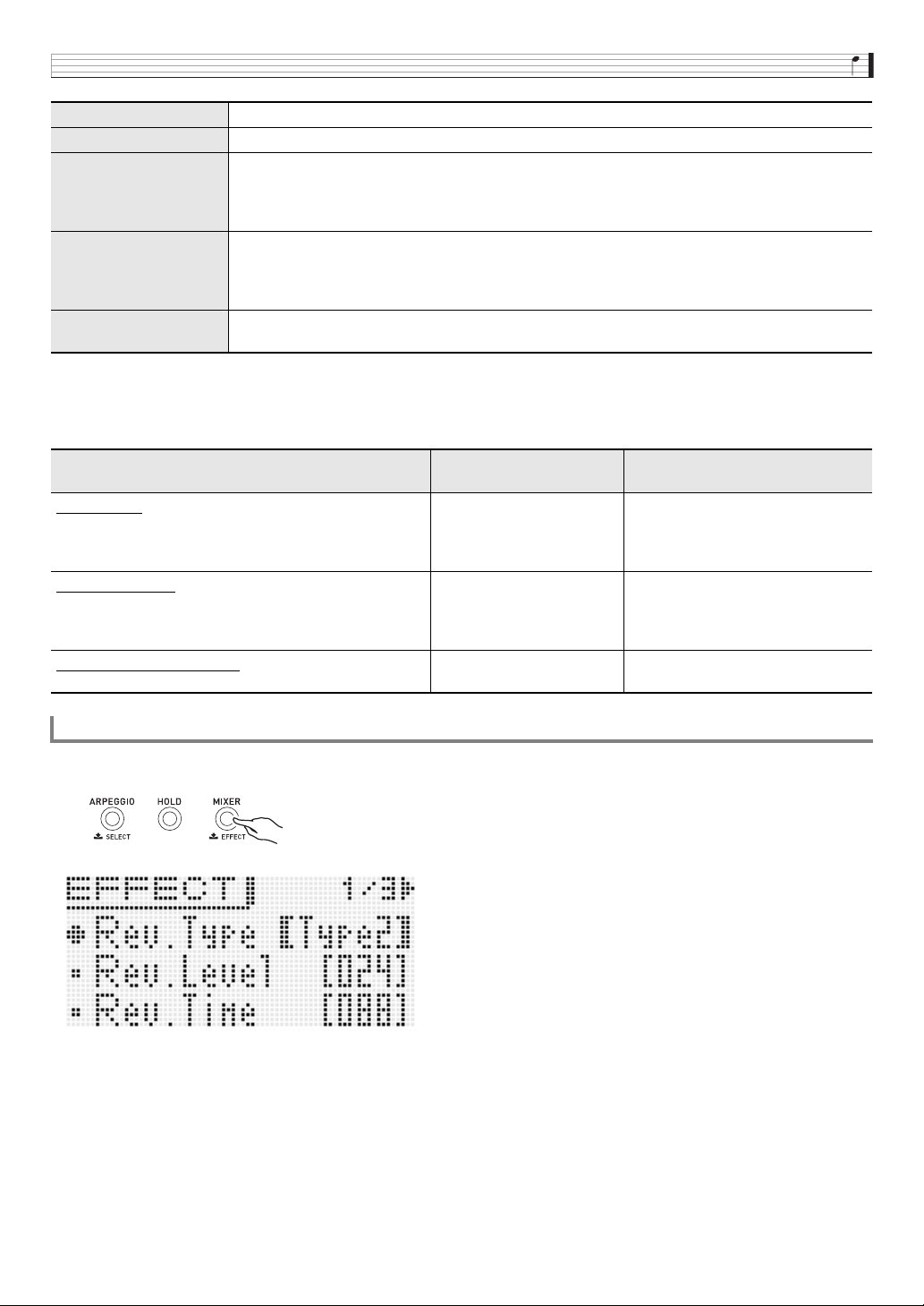
Selecting and Creating Tones
E-37
* When a tone with DSP (tone that uses a particular DSP) that is not a Solo Synthesizer tone is selected. A tone with DSP will
have “DSP” next to its display name on the mixer screen (page E-78) or performance editing screen (page E-73).
■ Chorus and DSP Use Restrictions
Only one of the three effect types (Chorus, Normal DSP, Solo Synthesizer DSP) can be enabled at any time.
1.
Hold down
bn
EFFECT until the effect list top screen shown below appears.
(1) Reverb Adds reverberation to make it sound like you are playing in a room or in a hall.
(2) Chorus Combines multiple layers of the same note to create a sound with more depth.
(3) Normal DSP A collection of versatile Normal DSP effects help to enhance the sound of tones. For example,
distortion can be applied to an electric guitar sound to make it sound more powerful. There are 46
different Normal DSP types, and the most appropriate one for the selected tone is applied
automatically.
*
A DSP can be edited and saved as a user DSP.
(4) Solo Synthesizer DSP One of the elements that makes up a Solo Synthesizer tones. See “(7) Total Block” in the “Editable
Parameters for Solo Synthesizer Tone” on page E-21. There are six Solo Synthesizer DSP types.
When you edit a Solo Synthesizer DSP, it is saved as part of a Solo Synthesizer user tone. You
cannot save it as a user DSP.
(5) Master Equalizer Adjusts the frequency characteristics of the Synthesizer’s notes. The Master Equalizer can be used
to adjust the frequency and gain of four frequency bands: low, mid1, mid2, and high.
Under this condition: This type of effect is valid:
And effects are applied to each
part like this:
Chorus Mode
• A tone other than the Song Sequencer is selected by
Zone Part 1, and the Chorus is selected by “Chorus/
DSP Select” (page E-38).
(2) Chorus Depends on the mixer chorus send
value (page E-80) and the selected
tone chorus send value (page E-29).
Normal DSP Mode
• A tone other than the Song Sequencer is selected by
Zone Part 1, and the DSP is selected by “Chorus/DSP
Select” (page E-38).
(3) Normal DSP (3) is applied only to parts whose
mixer DSP line (page E-80) is on.
Solo Synthesizer Tone Mode
• Solo Synthesizer tone selected by Zone Part 1.
(4) Solo Synthesizer DSP (4) is applied only to Zone Part 1 and
parts whose mixer DSP line is on.
To configure effect settings
bn
Selecting and Creating Tones
E-38
2.
Next, refer to the list below as you perform operations with the
br
controls to select items and change
settings.
■ Effect Settings
Display Description Settings
Rev Type Reverb type. Reverb effect type. Type1, Type2
Rev Level Reverb level. Reverb effect level. 0 to 127
Rev Time Reverb time. Reverb sustain time. 0 to 127
Cho Level Chorus level. Chorus effect level. 0 to 127
Cho Rate Chorus rate. Rate of chorus effect undulation. 0 to 127
ChoSendRev
Chorus send level to reverb. Specifies how reverb is applied to the entire sound to which
the chorus effect is being applied.
0 to 127
Cho/DSP
Chorus/DSP select. Selects use of either Chorus or Normal DSP (“Chorus and DSP Use
Restrictions”, page E-37).
Cho, DSP
DSP Select >Ent
Displays the main Normal DSP selection screen.
• You will not be able to go any further if a Solo Synthesizer tone is selected for Zone
Part 1.
(Normal DSP
selection
screen)
You can select from among preset and user tones for the Normal DSP using the same
procedures as those for tone selection.
• For a list of preset Normal DSPs, see the separate “Appendix”. Selecting “ton” applies
the initial preset DSP of each tone.
• Pressing
7
EDIT while this screen is displayed will change to the DSP editing screen
(page E-39).
ton
Preset: 0-0 to 9-9
User: 0-0 to 9-9
Master EQ >Ent Master equalizer setting group (item (5) of the “Effect Block Diagram” on page E-36)
EQ Enable Turning this setting off disables the Master EQ setting. Off, On
Low Freq Low frequency band. Adjusts the low frequency band.
200 Hz, 400 Hz,
800 Hz
Low Gain Low gain. Adjusts the low gain. –12 to 0
*
to +12
Mid1 Freq Mid 1 frequency band. Adjusts the mid1 frequency band. 1.0 kHz to 5.0 kHz
Mid1 Gain Mid1 gain. Adjusts the mid1 gain. –12 to 0
*
to +12
Mid2 Freq Mid 2 frequency band. Adjusts the mid2 frequency band. 1.0 kHz to 5.0 kHz
Mid2 Gain Mid2 gain. Adjusts the mid2 gain. –12 to 0
*
to +12
High Freq High frequency band. Adjusts the high frequency band.
6.0 kHz, 8.0 kHz,
10.0 kHz
High Gain High gain Adjusts the high gain. –12 to 0
*
to +12
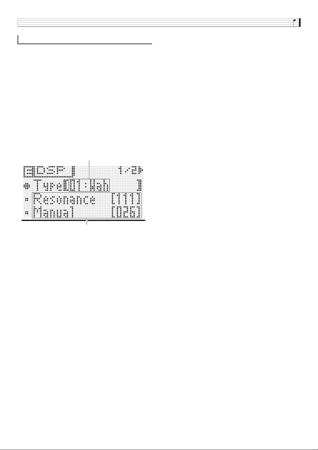
Selecting and Creating Tones
E-39
DSPs are divided among 53 DSP types according to effects.
Preset Normal DSPs 0-0 and 0-1 are compressor type DSPs.
There are two DSP types: a Normal DSP specific type and a
Solo Synthesizer DSP specific type.
When editing and saving a DSP, you must first specify its type
and then edit it in accordance with its type.
• For a list of DSP types, see “DSP Type List” on page E-99.
1.
Select the tone to which you want to apply the
DSP. Next, on the editing screen of the tone,
select DSP Edit >Ent (page E-29) and then press
br
ENTER to display the DSP editing screen
shown below.
• When editing a Normal DSP, you can display the DSP
editing screen from the Normal DSP selection screen
(page E-38) by pressing
7
EDIT.
2.
Use the
bp
dial to select a DSP type number.
3.
Use the same operation as these for tone
editing (page E-20) to select and configure the
DSP parameters on the screen.
• DSP parameters depend on the DSP type. For details,
see the “DSP Parameter List” (page E-100).
4.
After you finish editing a DSP, save it as
described below.
Press
7
WRITE to display the screen for saving a user
tone. Save the data as a user tone (page E-12).
• If you displayed the DSP editing screen from the
Normal DSP selection screen (page E-38) in step 1
Press
7
WRITE to display the screen for saving a
DSP. Save the edited DSP as a user DSP using the
same operation as that for a user tone.
■ Saving a User DSP to an External Device
• Memory card (page E-86)
• Computer (page E-92)
Saving an Edited DSP
DSP type number: type name
DSP parameter
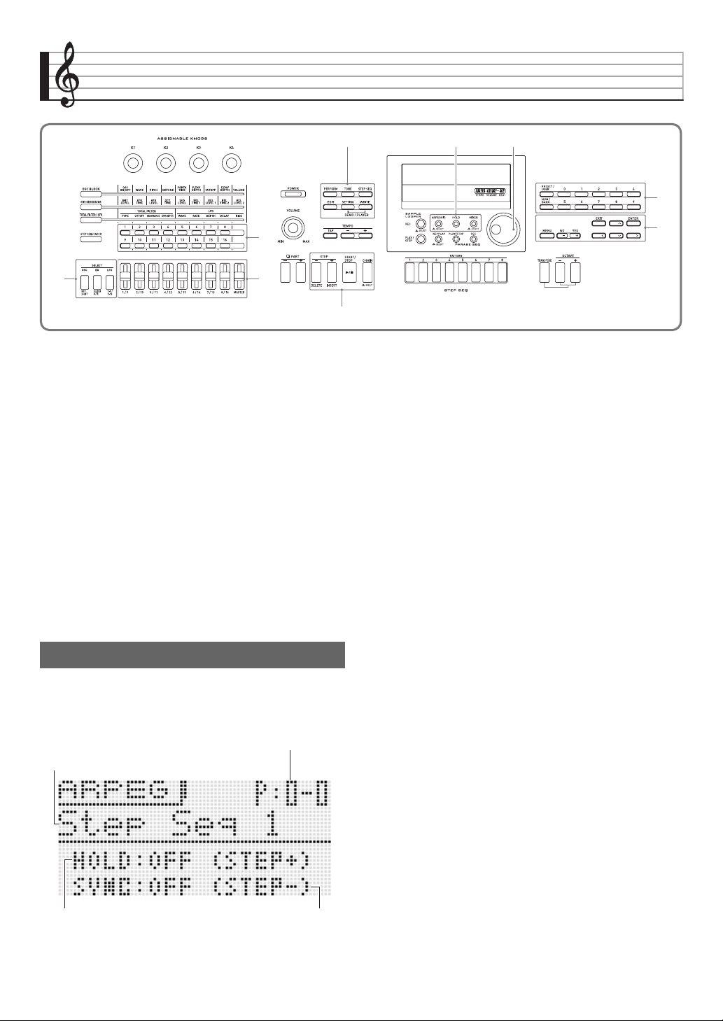
E-40
Sounding Arpeggios Automatically
With the Arpeggio Function, you can play various arpeggios
automatically by simply pressing keys on the keyboard. You
can select from a number of different arpeggio types for
playback, including arpeggios using the notes that make up a
chord you play on the keyboard, arpeggios that also include
notes that are automatically inserted in addition to those that
make up a chord you play on the keyboard, and more.
• The Arpeggio Function has 100 arpeggio type presets. A
type presets can be edited and saved as a user arpeggio
type. There is memory for up to 100 user arpeggio types.
• The following functions are also available for selecting an
arpeggio type.
1.
Hold down
bn
ARPEGGIO until the arpeggio
type selection screen shown below appears on
the display.
2.
Press
bq
PRESET/USER to select preset
arpeggios or user arpeggios.
• Preset arpeggios are selected while the button is unlit,
while user arpeggios are selected while the button is lit.
3.
Press the
bq
NUM/BANK button so the button
is flashing.
•While
bq
NUM/BANK is flashing, the
bq
(0 to 9)
buttons can be used to input a bank number.
4.
Use the
bq
(0 to 9) buttons to select a bank
number.
• Selecting a bank number will cause
bq
NUM/BANK to
stop flashing and become unlit. While
bq
NUM/BANK
is unlit, the
bq
(0 to 9) buttons can be used to input an
arpeggio number.
5.
Use the
bq
(0 to 9) to input an arpeggio number.
• You also can select an arpeggio number by rotating the
bp
dial.
• One more way to change the arpeggio number is to use
the
br
minus (–) and plus (+) buttons to decrease or
increase the displayed arpeggio number. Pressing the
br
minus (–) and plus (+) buttons at the same time
will jump to the first arpeggio number in the current
selected category (see next section).
7
bn
bp
br
5
bk
4
2
bq
Hold (HOLD) : The arpeggio continues to play after
keyboard keys are released. This is useful,
for example, when you use the Split
Function to insert an arpeggio on one part
of the keyboard.
Sync (SYNC) : The Step Sequencer automatically plays
and stops in sync with the Arpeggio
Function when keyboard keys are pressed.
To use the Arpeggio Function
Arpeggio bank and number
Hold setting Sync setting
Arpeggio name
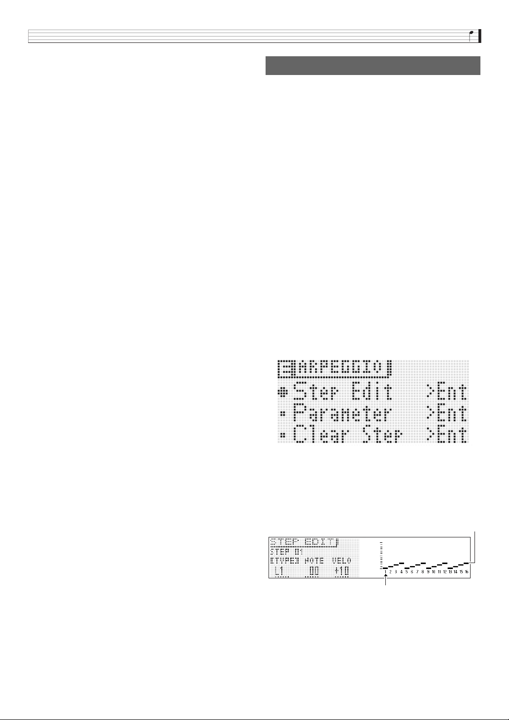
Sounding Arpeggios Automatically
E-41
6.
Select arpeggio hold or synchro ON/OFF.
• If you want to turn on the hold function (HOLD), press
bk
STEP +. Each press toggles HOLD between on and
off.
• If you want to turn on the sync function (SYNC), use
bk
STEP – to cycle through the available sync settings
described below.
• The HOLD and SYNC settings are performance
parameters.
7.
Press some keys and the arpeggio will start to
play automatically.
• To turn off the Arpeggio Function, press
bn
ARPEGGIO again.
• To stop arpeggio HOLD playback, press
bn
ARPEGGIO or change the HOLD function in step 2 of
the above procedure to OFF.
■ You can use the arpeggio type selection screen
to select the recommended tone for the currently
selected arpeggio type as your Zone Part 1 tone.
1.
Hold down
bn
ARPEGGIO until the arpeggio
type selection screen appears on the display.
2.
Hold down
7
EDIT until
bn
ARPEGGIO starts
to flash and then stops flashing to remain lit.
• In the case of a user arpeggio, the tone that was
selected as the Zone Part 1 tone when the user data
was saved is the recommended tone.
There are two arpeggio types: step type and variation type.
• With a step type arpeggio, you can edit its steps and its
parameters. A step type arpeggio can contain up to 16
steps. You can change the following values for each step.
• With a variation type arpeggio, you can edit only its
parameters.
1.
Hold down
bn
ARPEGGIO until the arpeggio
type selection screen shown below appears on
the display.
2.
From among the preset or user arpeggio types
select the arpeggio type you want to edit.
• For information about how to select an arpeggio type,
see steps 2 through 5 under “To use the Arpeggio
Function” (page E-40).
3.
Press
7
EDIT.
4.
Use the
br
up (q) and down (w) buttons to
move the item selection cursor (0) to “Step
Edit”, and then press
br
ENTER.
• The “Step Edit” option will not be displayed if you
selected a variation type arpeggio in step 2 above.
OFF : The arpeggio will play while keyboard keys are
depressed.
ON : The arpeggio will continue to play even after the
keyboard keys are released
OFF : Sync setting is turned off.
ON : Arpeggio play is synced with only the play
operation of the Step Sequencer.
S/S : Arpeggio play is synced with both the play and
stop operations of the Step Sequencer.
Editing an Arpeggio
TYPE : Specifies the relative position in the arpeggio
pattern where each of the keyboard notes will play.
You can specify positions starting from the lowest
note played (L1) or from the highest note played
(U1). You can even specify simultaneous play of up
to five notes (P2 through P5).
NOTE: Specifies a relative shift, in semitone steps, from
the note played on the keyboard.
VELO : Specifies the volume of the note.
Step type
Step number
Sounding Arpeggios Automatically
E-42
5.
Use the
bp
dial or the
br
minus (–) and plus (+) buttons to change the TYPE, NOTE, and VELO settings.
• You can also use the
4
1 to 16 buttons to toggle each step on or off.
•While TYPE is selected, use the
br
minus (–) and plus (+) buttons to turn the TYPE setting on or off.
• You can use
5
(eight sliders excluding “MASTER”) to change the values of the applicable step directly. When using the
sliders, press
2
1-8/9-16 to toggle between steps 1 through 8 (button unlit) and steps 9 through 16 (button lit). Note,
however, that you will not be able to use the sliders when TYPE is TIE and OFF.
• You can specify the tie setting. For details how, see “To configure tied note settings” on page E-53.
• The table below shows the contents of the arpeggio step editing menu.
6.
After the TYPE, NOTE, and VELO settings are the way you want, press
br
EXIT to return to the arpeggio
menu screen.
7.
Use the
br
up (q) and down (w) buttons to move the item selection cursor (0) to “Parameter”, and
then press
br
ENTER.
Menu Layer
Description Settings
1 2
Step Edit >Ent
TYPE
Specifies the relative position in the arpeggio pattern where the keyboard notes will play starting
from the lowest note played (which is L1).
• If the number of keys pressed is less than the number of configured type (L) settings (i.e. if you
press only three keyboard keys for an arpeggio pattern that includes settings for L1 through L6),
the arpeggio pattern will repeat, playing the keyboard key notes one octave higher.
• At any point the above causes the range of one higher octave to be exceeded, arpeggio play will
return to the L1 note automatically.
L1 to L8
Specifies the relative position in the arpeggio pattern where the keyboard notes will play starting
from the highest note played (which is U1).
• If the number of keys pressed is less than the number of configured type (U) settings (i.e. if you
press only three keyboard keys for an arpeggio pattern that includes settings for U1 through
U6), the arpeggio pattern will repeat, playing the keyboard key notes one octave lower.
• At any point the above causes the range of one lower octave to be exceeded, arpeggio play will
return to the U1 note automatically.
U1 to U8
Specifies how many of the notes played on the keyboard, starting from the highest note played,
should be played simultaneously.
• When the number of keys pressed is less than the polyphony (P) value specified here, only the
notes that are played are sounded.
P2 to P5
NOTE Shifts the notes produced by pressing keys in semitone steps. –24 to +24
VELO Changes the velocity of pressed keys. –64 to +63
Sounding Arpeggios Automatically
E-43
8.
Use the
bp
dial or the
br
minus (–) and plus (+) buttons to change the parameter settings.
• The table below shows the contents of the parameter editing menu.
9.
After you finish arpeggio parameter editing, save it as described below.
•Press
7
WRITE to display the screen for saving arpeggio data. Save the arpeggio by performing the same operation as
that for saving a user tone (page E-12).
• For information about deleting data you saved, see page E-83.
■ Saving Arpeggio Data on an External Device
• Memory card (page E-86)
• Computer (page E-92)
Menu Layer
Description Settings
1 2
Parameter >Ent
Max Step Maximum step. Can be edited only by step type. 1 to 16
Step Size Step size. Specifies the note length between steps. 2, 6,, 7,, 8
NoteLngth
Note length. Specifies the length of the note that is sounded as
a percentage of the step size. (100% for the same length as
the original, 50% for half the original.)
1 to 100%
Groove
Groove. Specifies the timing of the up beat step. (50% for
even. Larger values increase the length of the first half of the
note.)
10 to 90%
Grv.Type
Groove type. Specifies the note length when the Groove
setting is anything besides 50%.
Norml: Plays back at the actual percentage of the
step length.
Short: Adjusts to a short step in accordance with the
step.
Velocity
Velocity. Specifies the velocity of an input arpeggio. Specifying
KeyOn inputs a velocity value in accordance with the degree
of key pressure applied.
KeyOn, 1 to 127
Hold Pedal Hold pedal. Specifies on/off switching for hold used by a pedal. On, Off
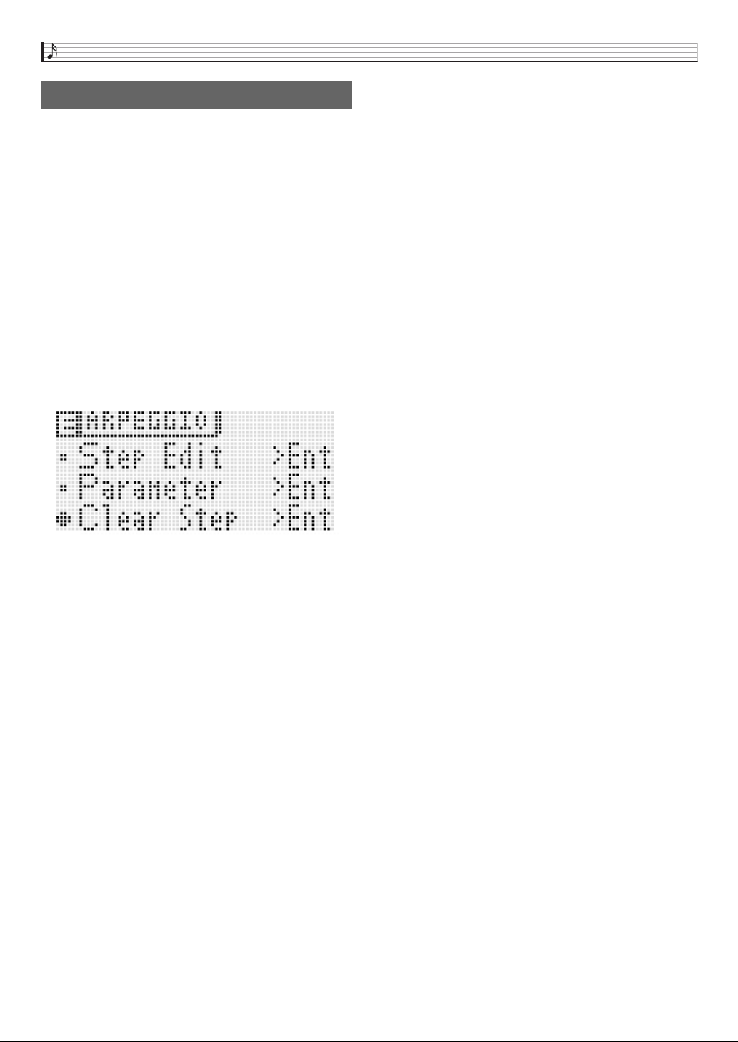
Sounding Arpeggios Automatically
E-44
Use the procedure below to clear preset step data or step
data that was edited using Step Edit (page E-42) and create
new step data from scratch.
• Note that variation type data cannot be cleared.
1.
Hold down
bn
ARPEGGIO until the type
selection screen shown below appears on the
display.
2.
From among the preset or user arpeggio types
select the arpeggio type you want to clear.
• The procedure for selecting an arpeggio type is the
same as that for selecting a tone (page E-19).
3.
Press
7
EDIT.
4.
Use the
br
up (q) and down (w) buttons to
move the item selection cursor (0) to “Clear
Step”, and then press
br
ENTER.
5.
Press
br
ENTER again.
This should cause “Clear?” to appear on the display.
6.
Press
br
YES.
The message “Complete!” will appear on the display when
the data is cleared.
Clearing Arpeggio Data
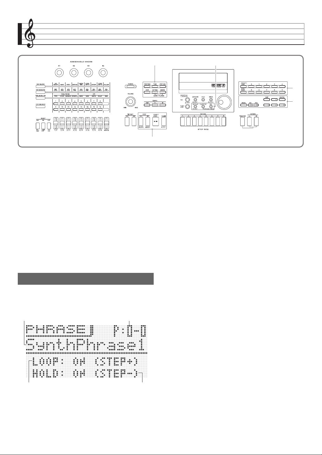
E-45
Recording and Playing Back Phrases
The Phrase Sequencer is a great way to record musical
phrases that suddenly pop into your mind for later playback.
• The Sequencer has 100 preset phrases.
• You can record a new phrase or overdub onto an existing
phrase to create a user phrase. There is memory for
storage of up to 100 user phrases for later recall when you
need them.
• In addition to what you play on the keyboard, your pedal,
wheel, and knob operations are also recorded as part of
phrase.
• You can choose either of two different playback options:
one-time playback (loop off) or repeat playback (loop on).
• Overdubbing during looped playback is supported. You
also can temporarily cancel overdubbing and perform
looped playback only.
• Pressing a keyboard key will start playback of the phrase
from the corresponding pitch (Key Play).
1.
Hold down
bo
KEY PLAY until the preset
phrase selection screen shown below appears
on the display.
2.
Select the number of the phrase you want to
play.
• To select a phrase number, perform steps 2 through 5
under “To use the Arpeggio Function” (page E-40).
3.
Press
bk
STEP + to toggle looping between on
and off.
4.
Press
bk
STEP – to toggle hold between on and
off.
5.
Press
bo
PLAY/STOP to start phrase playback.
• If the phrase is looped, the
bo
PLAY/STOP light will go
out momentarily to indicate when playback returns to
the beginning of the phrase.
• You can also use the above procedure to play back
user phrases as well.
• Phrase loop and hold settings are saved as parameters
for each phrase.
7 bo
bq
br
bk
To play back a preset
Phrase number
Loop setting Hold setting
Phrase name
OFF : One-time playback
ON : Looped playback
OFF : Phrase plays back only while
bo
PLAY/STOP is
depressed, and stops when the button is released.
ON : Phrase playback starts when
bo
PLAY/STOP is
pressed and stops when
bo
PLAY/STOP is
pressed again.
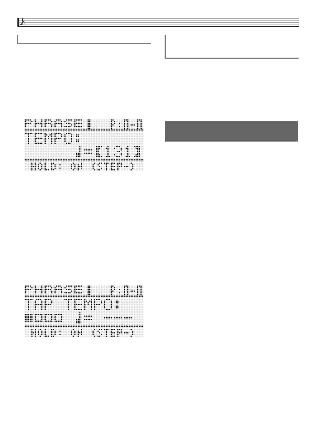
Recording and Playing Back Phrases
E-46
There are two different methods you can use to change the
tempo setting: using the TEMPO buttons or tapping a beat
with a button.
• You can use this procedure to adjust the tempo not only for
phrases, but also for other functions as well.
■ To change the tempo using the TEMPO buttons
1.
Press the
8
TEMPO – (slower) or
8
TEMPO +
(faster) button.
• This displays the tempo screen shown below.
• If you do not perform any operation for a few seconds,
the display will return to previous screen automatically.
2.
Use the
8
TEMPO –, + buttons to change the
tempo (beats per minute).
• Holding down either button or rotating the dial will scroll
the tempo values at high speed.
• You can specify a tempo value in the range of 30 to
255.
3.
Press the
br
EXIT button.
• This exits the tempo screen.
■ To adjust the tempo by tapping a beat
1.
TAP the
8
TAP button four times at the speed
(tempo) you want to set.
• The tempo setting will change in accordance with your
tapping speed as soon as you tap the fourth time.
2.
After setting the tempo by tapping, you then
can use the procedure under “To change the
tempo using the TEMPO buttons” (page E-46) to
make fine adjustments.
1.
Hold down
bo
KEY PLAY until the phrase
selection screen appears on the display.
2.
Hold down
7
EDIT until
bo
KEY PLAY starts to
flash.
• In the case of a user phrase, the tone that was selected
as the Zone Part 1 tone when the user data was saved
is the recommended tone.
1.
Press
bo
KEY PLAY so the button becomes lit.
2.
Press keyboard key to start playback of the
phrase.
• If the key you press to start phrase playback is higher
or lower than the phrase’s original pitch, the phrase will
play at the pitch of pressed key.
• When the hold setting is turned off, the phrase is played
only while the keyboard key is depressed, and stops
when the key is released. When the hold setting is
turned on, phrase playback starts when the keyboard
key is pressed and does not stop until the
bo
PLAY/
STOP key is pressed.
• You can use the “PhrKeyRgLo” and “PhrKeyRgHi”
settings to specify the high point and the low point of
the keyboard where Key Play can be performed (page
E-75).
To change the tempo setting
You can use the phrase selection screen to
select the recommended tone for the currently
selected phrase as your Zone Part 1 tone.
To start phrase playback by
pressing keyboard key (Key Play)
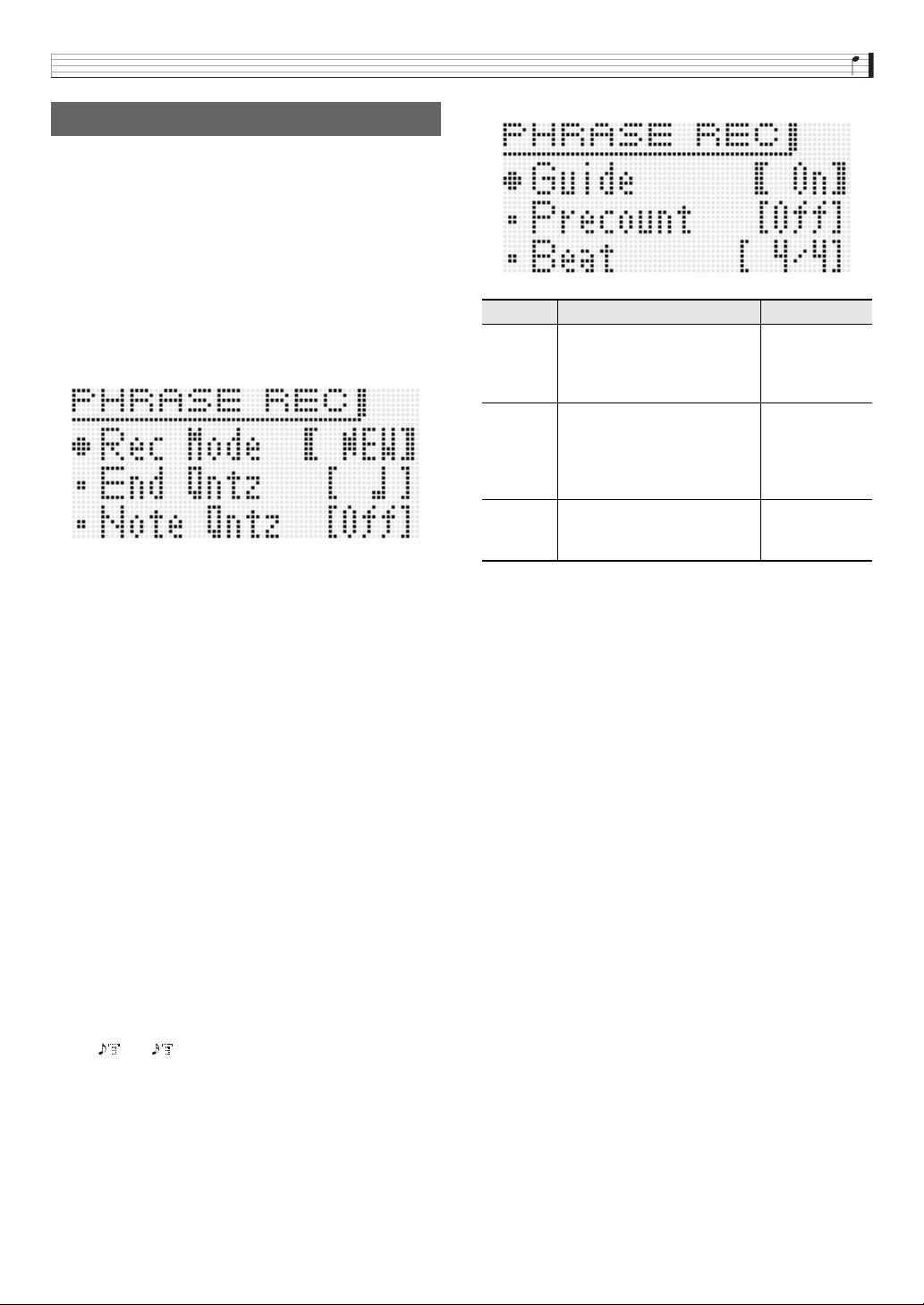
Recording and Playing Back Phrases
E-47
In addition to what you play on the keyboard, pedal, knob, and
wheel operations are also recorded in phrases.
• You can record up to approximately 1,600 notes for a single
phrase. Also, recorded wheel and knob operations
significantly reduce the remaining number of notes
available for recording.
1.
Press
bo
REC.
This will cause the
bo
REC light to flash.
• If OVDB (overdubbing) is displayed as the “Rec Mode”
setting, use the
br
minus (–) and plus (+) buttons to
change it to NEW (new phrase). This will enter the new
phrase recording standby mode.
• End quantize and note quantize settings can be
configured as required.
■ End Quantize (End Qntz)
When you perform a button operation to end recording of a
new phrase, there is a chance that your timing may be off.
The end quantize settings described below can be used to
correct the timing of the end point automatically and make its
positioning more natural.
■ Note Quantize (Note Qntz)
When recording keyboard play, there may be cases when
your timing strays a bit. The note quantize settings described
below can be used to correct the timing of keyboard play
automatically and correct the timing of notes you play on the
keyboard. (Note that only key press timing is correct. The
timing of other operations such as key release, and wheel,
pedal, and knob operations are not corrected.)
•Pressing
br
MENU will display a menu of the detailed
settings shown below. Use the
br
up (q) and down
(w) buttons to select a parameter and then use the
br
minus (–) and plus (+) buttons to change its
setting.
2.
Recording will start when you press the
bo
REC, or when you start to play by performing a
pedal, knob, or wheel operation or play
something on keyboard.
bo
REC will light when recording starts.
3.
When recording reaches the point where you
want to stop, press
bo
PLAY/STOP.
bo
REC will become unlit and “!TEMP” (temporary) will
appear for the phrase number.
• Pressing
bo
REC in place of
bo
PLAY/STOP in step 3
above will stop recording, temporarily change to the
overdub standby mode, and start looped playback of
the phrase you have recorded. For details about
overdubbing, see “Recording Over Another Phrase
(Overdubbing)” (page E-48).
4.
After you finish recording, save the data as
described below.
• Press
7
WRITE to display the screen for saving a
phrase (page E-49).
• For information about deleting data you saved, see
page E-83.
■ Saving a Phrase to an External Device
• Memory card (page E-86)
• Computer (page E-92)
Recording a New Phrase
Off : Phrase end point timing not adjusted.
1M: Phrase end point is adjusted to measure-unit
positions.
2 : Phrase end point is adjusted to quarter note-unit
positions.
6 : Phrase end point is adjusted to eighth note-unit
positions.
Off : Timing not adjusted. (Notes are
recorded as played.)
6
, , 7, : Timing of actual keyboard play is
corrected to the nearest note in
accordance with the specified note unit.
Menu Description Setting Range
Guide
Guide tone. Specifies whether
or not a count tone is sounded
during phrase recording and/or
record standby.
Off, On
Precount
Precount. Specifies the
number of measures of count
to be inserted prior to the start
of button operation triggered
phrase recording.
Off,
1:1 measure,
2:2 measures
Beat
Beat. Specifies the beat when
Guide, Precount, or end
quantize 1M is being used.
2/4 to 8/4,
2/8 to 16/8
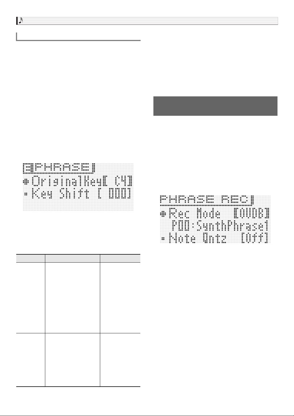
Recording and Playing Back Phrases
E-48
When playing on keyboard to start phrase playback (page
E-46), the phrase data will play back in the key it was
originally recorded in (Original Key) if you press the key for
the first note recorded in the phrase.
Phrase data settings can be used to specify that playback
should be performed using the originally recorded notes, even
when keyboard keys are pressed for notes other than those in
the original phrase data. Each phrase has a Key Shift setting
that you can use to change the pitch of the original key in
semitone steps.
1.
Hold down
bo
KEY PLAY until the phrase
selection screen appears on the display.
2.
Select the number of the phrase whose settings
you want to configure.
• To select a phrase number, perform steps 2 through 5
under “To use the Arpeggio Function” (page E-40).
3.
Press
7
EDIT.
4.
Use the
br
up (q) and down (w) buttons to
select a parameter and then use
bq
or the
br
minus (–) and plus (+) buttons to change its
setting.
* “C-” on the display indicates C-1 (one octave below C0).
5.
After you finish configuring settings, save them
as described below.
• Press
7
WRITE to display the screen for saving a
phrase (page E-49).
• For information about deleting data you saved, see
page E-83.
■ Saving a Phrase to an External Device
• Memory card (page E-86)
• Computer (page E-92)
1.
Select the phrase you want to overdub.
• To select a phrase number, perform steps 2 through 5
under “To use the Arpeggio Function” (page E-40).
2.
Press
bo
REC.
This will cause
bo
REC to flash.
• If NEW is displayed as the “Rec Mode” setting, use the
br
minus (–) and plus (+) buttons to change it to
OVDB (overdubbing). This will enter the overdubbing
standby mode. A phrase number and name will be
shown on the display, but you cannot select a phrase at
this time.
• If you want, configure the note quantize (Note Qntz)
setting (page E-47) at this time.
3.
Press
bo
REC or start playing with a pedal,
knob, or wheel operation, or by playing
something on the keyboard. Any one of these
operations will start overdub recording.
This will cause
bo
REC and
bo
PLAY/STOP to light
(without flashing).
• The original phrase will playback as a loop. Anything
you play on the keyboard and any operations you
perform during loop playback will be overdubbed onto
the original phrase.
4.
When recording reaches the point where you
want to stop, press
bo
PLAY/STOP.
bo
REC and
bo
PLAY/STOP will become unlit and an
exclamation point ( ! ) will appear next to the phrase
number.
Phrase Data Settings
Menu Description Setting Range
OriginalKey
Original Key. Specifies
the keyboard key that
corresponds to the first
note of the phrase played
by Key Play. (The initial
Original Key default
settings the note played
when the phrase was
recorded.)
• Setting can be
specified using the
keyboard keys.
C- to G9*
Key Shift
Key shift. Specifies the
key shift, in semitone
steps, of a phrase when
the keyboard key
corresponding to the
original is or the PLAY/
STOP key is pressed.
(To disable key shift,
specify 000.)
–127 to 000 to
+127
Recording Over Another Phrase
(Overdubbing)
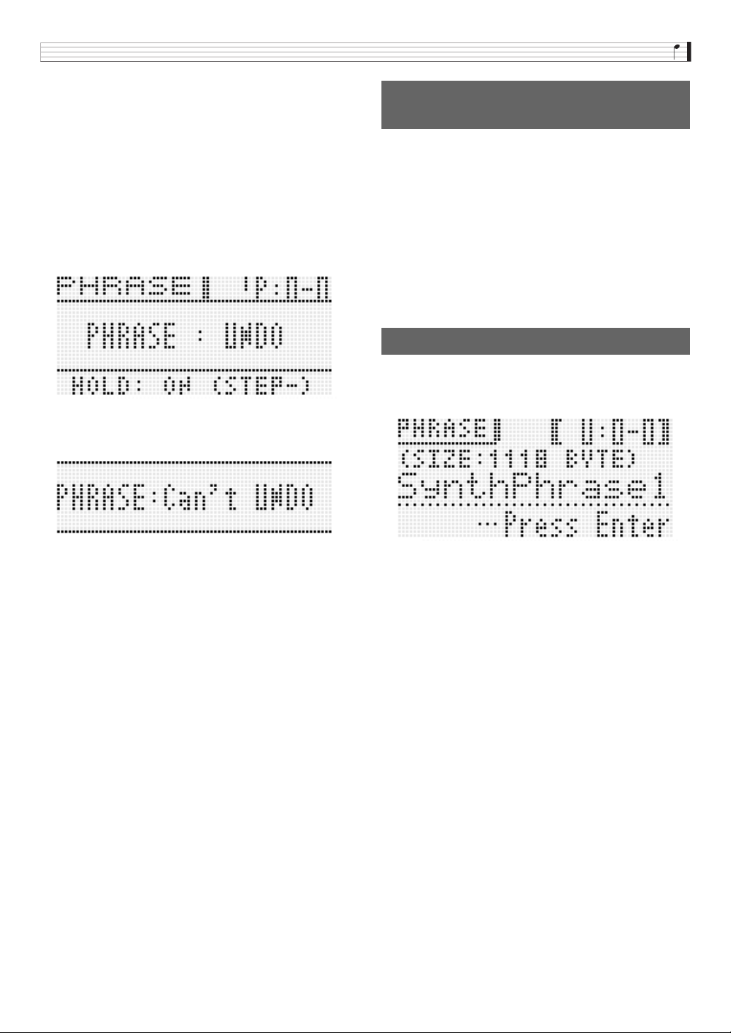
Recording and Playing Back Phrases
E-49
■ To pause overdubbing during looped playback
In step 4 of the above procedure, press
bo
REC instead of
bo
PLAY/STOP.
• This will cause
bo
REC to start flashing.
• Though what has been recorded up to that point continues
to play as a loop, further recording is not possible while
overdubbing is paused.
• Press
bo
REC again to resume overdubbing.
■ To delete the last recorded data (undo)
While phrase playback is in progress or stopped, or while
overdubbing is in progress or paused, hold down
bo
REC
until the undo screen appears.
• The message “Can’t UNDO” will be appear on the display if
you try to perform an undo operation again after already
undoing the last recording.
• A phrase that has been saved as a user phrase cannot be
undone.
The meanings of the indicators that are appended to the
phrase number on the display are described below.
• If you change the phrase number selection in step 2 of the
procedure under “To play back a preset” (page E-45) while
an exclamation point ( ! ) is appended to the currently
selected phrase number (indicating that it is an unsaved
user phrase), the unsaved user phrase will be discarded.
To save an unsaved user phrase, use the procedure under
“To save a phrase”, below.
Press
7
WRITE to display the screen for saving a phrase.
Save the phrase by performing the same operation as that for
saving a user tone (page E-12).
• If there is not enough Synthesizer memory space available
to store the phrase data, the message “not enough space”
will appear on the above display in place of “Press Enter”,
and you will not be able to save the phrase data. If this
happens, delete some of the user data in Synthesizer
memory to free up memory space.
• The Synthesizer can store up to 100 user phrases with a
combined total of up to 128KB.
• For information about deleting phrase data you saved, see
page E-83.
■ Saving a Phrase to an External Device
• Memory card (page E-86)
• Computer (page E-92)
Indicators Next to Phrase
Numbers
! : Unsaved phrase
* : Saved user phrase
!TEMP: Newly recorded phrase that has not been saved
To save a phrase
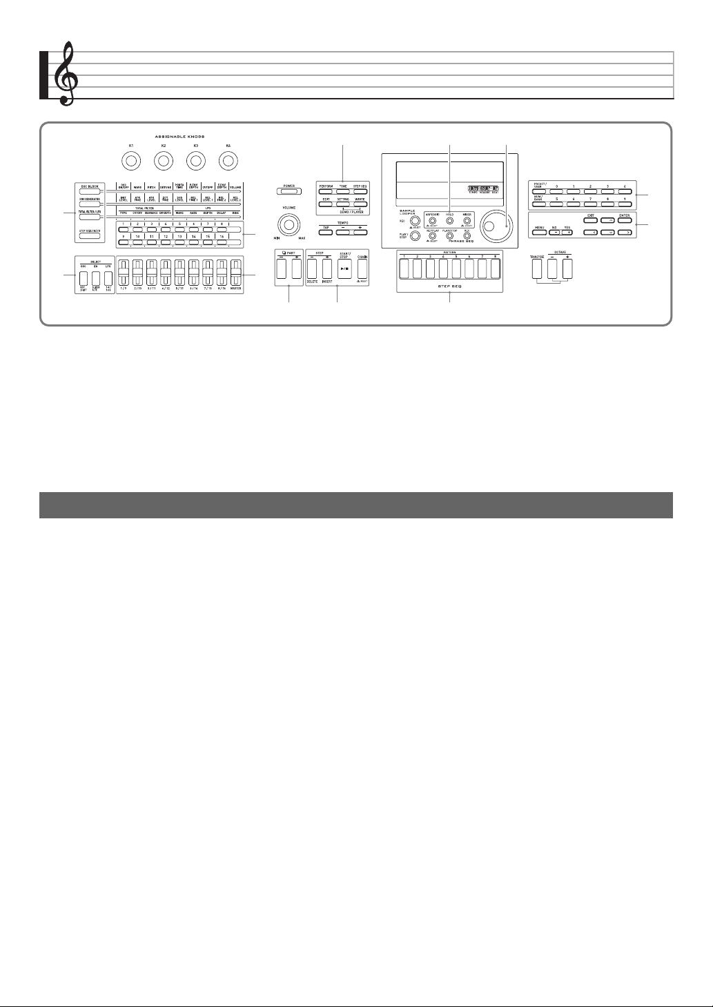
E-50
Using the Step Sequencer
The Step Sequencer provides up to 16 steps. The Synthesizer’s sliders can be used to control step notes and velocity in real time.
The Step Sequencer is not just a rhythm machine, it makes it possible for you to compose music as you play on the keyboard.
You can edit each step of a preset sequence to create your own rhythm pattern and save the result as a user sequence.
• The Step Sequencer has 100 preset sequences. You also can store up to 100 of your own user sequences.
• There are two ways to edit a step: simple editing without using the editing screen, and the editing screen that provides more
detailed modification of a step.
• Wheel (bender, modulation) and knob operations can also be recorded as part of a sequence.
• Up to 99 different patterns can be chained together with the Step Sequencer and played back as a loop. You can store up to 100
chained sequences.
• Phrase Sequencer playback can be started from the Step Sequencer.
The following describes the configuration of a single sequence.
• A part (PART) consists of nine note parts (Drum 1 to 5, Bass, Solo 1 and 2, Chord) and four control parts.
• The control parts can be configured with pitch bends/control changes and Phrase Sequencer play triggers (that start and stop
playback).
• For details about the settings and other information about each part, see “Editing a Sequence - Advanced” on page E-56.
• Each sequence has eight different patterns. You can configure separate beat (Beat Info) for each of the eight patterns.
• A track consists of data 16 steps along with their track parameters.
• You can use the Synthesizer’s mixer function to change Step Sequencer tones. For details, see “Using the Mixer” on page E-78.
How the Step Sequencer is organized
9 bl
7
bn
bp
bq
br
5
bk
4
2
1
Using the Step Sequencer
E-51
8ch
9ch
10ch
11ch
12ch
13ch
14ch
15ch
16ch
AB
AB
AB
AB
AB
AB
AB
AB
AB
3456789
10 11 12 13 14 15 16
12
Track
Track
Track
Track
Track
Track
Track
Track
Track
Track
Track
Track
Track
Drum 1
Drum 2
Drum 3
Drum 4
Drum 5
Bass
Solo 1
Solo 2
Chords
Control 1
Control 2
Control 3
Control 4
Beat
Sliders
(page E-53)
Master Slider
(page E-54)
Mixer
(page E-78)
Part
(page E-50)
Patterns 1 through 8
(page E-50)
Note Part
Control Part
Step Data
Track Parameters
• Maximum step
• Step size
•Others
Control Type
• Control track only
Off, On, Tie
Note 1 *Note 2 *Note 3 Velocity
Value Key shift
• Phrase only
* Control track only
Sequence Parts
Track
Note Part
Control Part
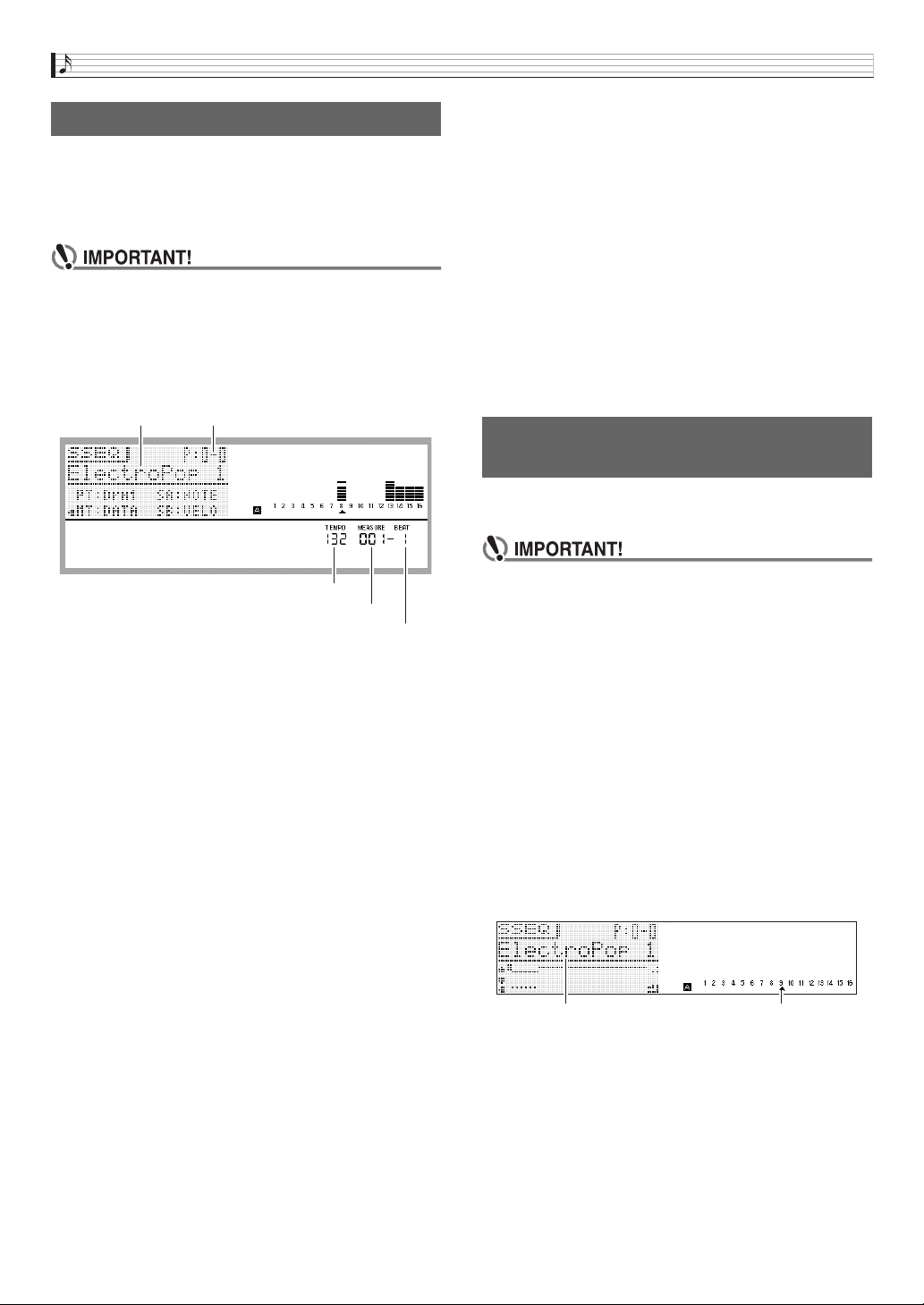
Using the Step Sequencer
E-52
A step sequence can be played back from the Performance,
Tone, or Step Sequencer Mode.
The step sequence can be changed by switching to a different
pattern, selecting a different sequence bank and number, and
by shifting the key (Key Shift).
•If the
bk
CHAIN button is lit (indicating the Chain
Mode), press
bk
CHAIN to turn off the light before
starting the procedure below.
1.
Press
bk
START/STOP.
The
bk
START/STOP button will flash and sequence
playback will start.
•Pressing
bk
START/STOP while playback is in
progress will stop the sequence and cause the
bk
START/STOP button light to go out.
• Step Sequencer playback can be performed
automatically, without pressing
bk
START/STOP, by
using the Arpeggio Function to specify Step Sequencer
playback triggers. For details, see the section of this
manual from “To use the Arpeggio Function” on page
E-40.
• For information about changing the playback tempo,
see “To change the tempo setting” (page E-46).
2.
To change to a different pattern, enter the Step
Sequencer Mode and press one of the
bl
PATTERN 1 to 8 buttons.
The light of the button whose pattern you select will go
out.
• When changing to a different measure, the light of the
button of the currently selected pattern will flash until a
point is reached where the change can be made.
• Pressing the button of the currently selected pattern will
cause its button light to flash, indicating that playback is
standing by to stop. Next, pressing
bk
START/STOP
will stop playback when it reaches the end of the
currently playing measure. To cancel the stop standby
operation described above, press the flashing button
again.
3.
If you want to change to a different sequence,
enter the Step Sequencer Mode and change the
sequence bank and/or number.
• To select a sequence, perform steps 2 through 5 under
“To use the Arpeggio Function” (page E-40).
4.
If you want to shift the key, press
1
STEP
SEQUENCER and then press
2
KEY SHIFT.
• When the original key is C2, you can shift the key by
pressing a keyboard key within the range of D2 to B2.
• You can specify whether or not to shift the key of each
individual part. For details, see the section of this
manual from “Editing a Sequence - Advanced” on page
E-56.
• The Key Shift on/off setting is saved as Performance
parameter.
Simple editing of a sequence can be performed from the
Performance, Tone, or Step Sequencer Mode.
•If the
bk
CHAIN button is lit (indicating the Chain
Mode), press
bk
CHAIN to turn off the light before
starting the procedure below.
1.
If the Synthesizer is in the Performance or Tone
Mode, press
1
STEP SEQUENCER.
This enters the Step Sequencer Mode, which causes the
1
STEP SEQUENCER button to light.
2.
Perform steps 1 through 3 of the procedure
under “Playing Back a Step Sequence” on page
E-52 to select the sequence and pattern you
want to edit.
3.
Use the
9
PART minus (–) and plus (+) buttons
to select the part you want to edit.
A pointer (e) will appear on the display under the number
of the currently displayed part.
• The pointer (e) does not appear on the display if you
select a control type part.
4.
Edit each part using the procedures in the
following sections.
Playing Back a Step Sequence
Sequence name
Beat
Sequence bank, number
Measure
Tempo
Editing a Sequence -Simple
Editing
Selected part numberSelected part name
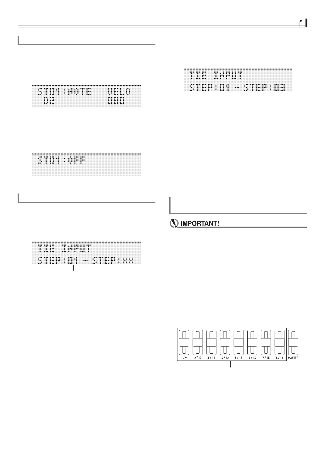
Using the Step Sequencer
E-53
■ On (Sounding)
Press the
4
1 to 16 button of the number of the step you
want to turn on.
When a step is on, its
4
1 to 16 button is lit and NOTE is
displayed next to its step number.
■ Off (Not sounding)
Press the
4
1 to 16 button of the number of the step you
want to turn off.
When a step is turned off, the light of its
4
1 to 16 button is
unlit and OFF is displayed next to its step number.
• There is no step on/off setting for a control part.
1.
While holding down
1
STEP SEQUENCER,
press the
4
1 to 16 button that corresponds to
the step number of the first note of the tied
group.
2.
Next, while holding down
1
STEP
SEQUENCER, press the
4
1 to 16 button that
corresponds to the step number of the last note
of the tied group.
• This turns on the step you specified as the start of the
tied group. It also ties together all of the notes from the
first step up to the last step.
• The
4
1 to 16 buttons that correspond to the step
numbers included in the tied group will all be flashing.
Release
1
STEP SEQUENCER and the button lights
will go out. (Even though the button lights go out, the
notes in the group remain tied.)
• To check which steps are tied, hold down
1
STEP
SEQUENCER and then press any one of the
4
1 to
16 buttons. This will cause the
4
1 to 16 buttons of
the steps included in the tied group to flash.
• A control part doe not have a tie setting.
•If the
1
STEP SEQUENCER button is not lit, press
1
STEP SEQUENCER to turn on the light before starting
the procedure below.
■ Slider Operations
Use
5
1/9 to 8/16 to change the note and velocity settings
(note part) of the notes of steps 1 through 16.
• In the case of a control part, the sliders can be used to
change the control effect. For details, see “Editing a
Sequence - Advanced” on page E-56.
•Press
2
1-8/9-16 to toggle slider operations between
steps 1 through 8 and steps 9 through 16.
• Step 1 through 8 operation is selected when the
2
1-8/
9-16 button is unlit. Step 9 through 16 operation is selected
when the
2
1-8/9-16 button is lit.
To turn a step on or off
To configure tied note settings
First step number
Using the Sliders to Change Note and
Velocity Settings
Last step number
Steps 1 through 8 or steps 9 through 16 (selectable)
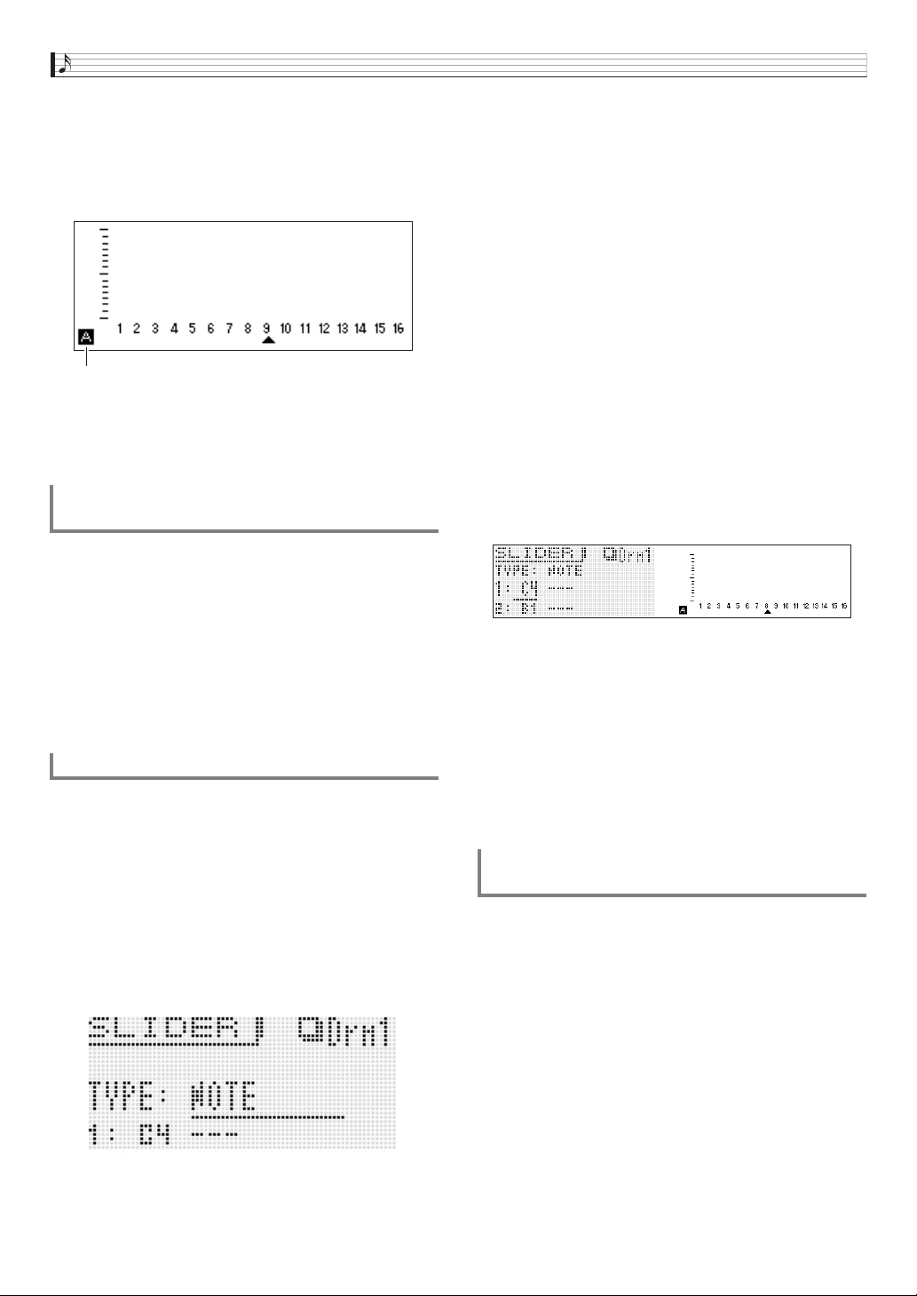
Using the Step Sequencer
E-54
■ Selecting a Slider Function
Pressing
2
SLIDER A/B toggles the sliders between two
functions.
Example: Preset sequence
2
SLIDER A/B unlit: L (NOTE)
2
SLIDER A/B lit: M (VELOCITY)
• Moving a
5
1/9 to 8/16 slider will turn on the
corresponding step, even if it is currently turned off.
• Slider function switching cannot be performed for a
control part.
You can use the
5
MASTER slider to batch change the
settings (note, velocity, staccato/tenuto, playback speed,
groove) of all of the parts.
• The settings that can be changed using the master slider
depend on the part type.
• For some parts, the master slider cannot be used to change
settings.
• You can assign other settings to the master slider, if you
want. For more information, see “Changing the Function
Assigned to the Master Slider” on page E-54 and
“Changing Slider Settings” on page E-60.
Under default settings, the A sliders have note settings
assigned to them, while the B sliders have velocity settings
assigned. You can use the procedure below to assign note
settings, velocity settings, or both note and velocity settings to
sliders.
You also can specify the note or velocity setting that is
selected at each of the eight slider positions.
1.
Press
1
STEP SEQUENCER.
2.
Hold down
2
SLIDER A/B until the SLIDER
screen shown below appears.
3.
Use the
9
PART minus (–) and plus (+) buttons
to select the part whose slider assignments you
want to change.
4.
Press
2
SLIDER A/B to select the set of sliders
(A or B) whose assignments you want to
change.
5.
Move the display cursor to “TYPE” and then
use the
br
NO and YES buttons to assign one
of the following functions to the selected
sliders.
6.
Use the
bp
dial, the
br
up (q) and down (w)
buttons, or the
bl
PATTERN (1 to 8) buttons to
move the display cursor to the slider position
(1 to 8) whose setting you want to change.
• The numbers 1 through 8 indicate the eight slider
positions, from top (8) to bottom (1).
7.
Use the
br
NO and YES buttons to change the
note or velocity value at the currently selected
slider position.
• You can also press the keyboard key that corresponds
to the note you want to input to specify the note and
velocity for the currently selected slider position.
• For a chord part, you can specify up to three values.
• Use advanced parameter editing to edit slider
functions. For details, see “Editing a Sequence -
Advanced” (page E-56).
1.
Press
1
STEP SEQUENCER.
2.
Hold down
2
SLIDER A/B until the SLIDER
screen appears.
3.
Press
br
MENU and then press the
br
right (I)
button to move the item selection cursor (0) to
“M.Slider”.
Using the Master Slider to Change Note and
Velocity Settings
Changing Slider Assignments
Indicates the selected function as L or M.
NOTE : Note
VELO : Velocity
NOTE & VELO : Both note and velocity
Changing the Function Assigned to the
Master Slider
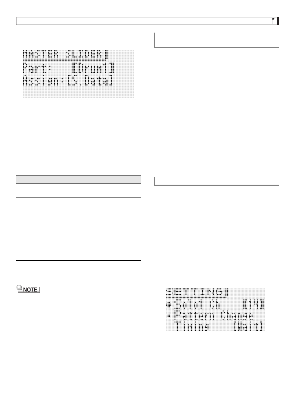
Using the Step Sequencer
E-55
4.
Press
br
ENTER.
This will display the master slider setting screen.
5.
Use the
br
minus (–) and plus (+) buttons and
the
9
PART minus (–) and plus (+) buttons to
display the name of the part you want to change
to inside the brackets % next to Part.
6.
Use the
br
up (q) and down (w) buttons to
move to the “Assign” setting, and then use the
bp
dial or the
br
minus (–) and plus (+) buttons
to change to one of the settings described
below.
• For details about step size, note length, and groove
assignments, see “Step Sequencer Parameters” on
page E-57.
• Slider functions can also be modified as described below.
For information about making these changes, see
“Changing Slider Settings” on page E-60.
– Copying settings from another slider
– Scale, drum, velocity slider presets
– Note shift
You can input note, velocity, and other step data by
performing keyboard, pitch bend, and knob operations as you
play.
• When inputting a pitch bend or knob operation, you first
need to use the control track to select the pitch bender or
knob and then perform in input.
1.
Press
7
EDIT.
2.
Use the
br
down (w) button to move the item
selection cursor (0) to “Step Edit”, and then
press
br
ENTER.
3.
Input data as described below.
■ While sequence playback is in progress
Press keyboard keys and perform other operations as
required according to the timing of playback.
■ While sequence playback is stopped
Perform input into the currently displayed step.
Solo1 is normally assigned to channel 14.
You can use the procedure below to change the assignment
to channel 1 when you want to use Solo Synth or other special
tones as the solo tone.
1.
Press
1
STEP SEQUENCER.
2.
Press
br
MENU and then press the
br
right (I)
button.
3.
After confirming that the item selection cursor
(0) is next to “Setting”, press
br
ENTER.
4.
Use the
br
up (q) and down (w) buttons to
move the item selection cursor (0) to “Solo1
Ch”.
5.
Use the
br
minus (–) and plus (+) buttons to
change the Solo1 channel setting.
• The Solo1 channel setting is saved as Performance
parameter.
Assign Description
Nop No operation. Master slider operation is
disabled.
S. Data Step data. Changes the data of all of the steps
(1 thorough 16) that are currently turned on.
S. Size Step size
NoteLn Note length
Groove Groove
Octave When there are notes assigned to sliders 1
through 8, moving the master slider when this
setting is in effect will change the octaves of
the notes (Range: –1 to 0 to 1).
Inputting Step Data by Playing on the
Keyboard, etc.
Changing the Solo1 Channel
1 : Channel 1
14 : Channel 14
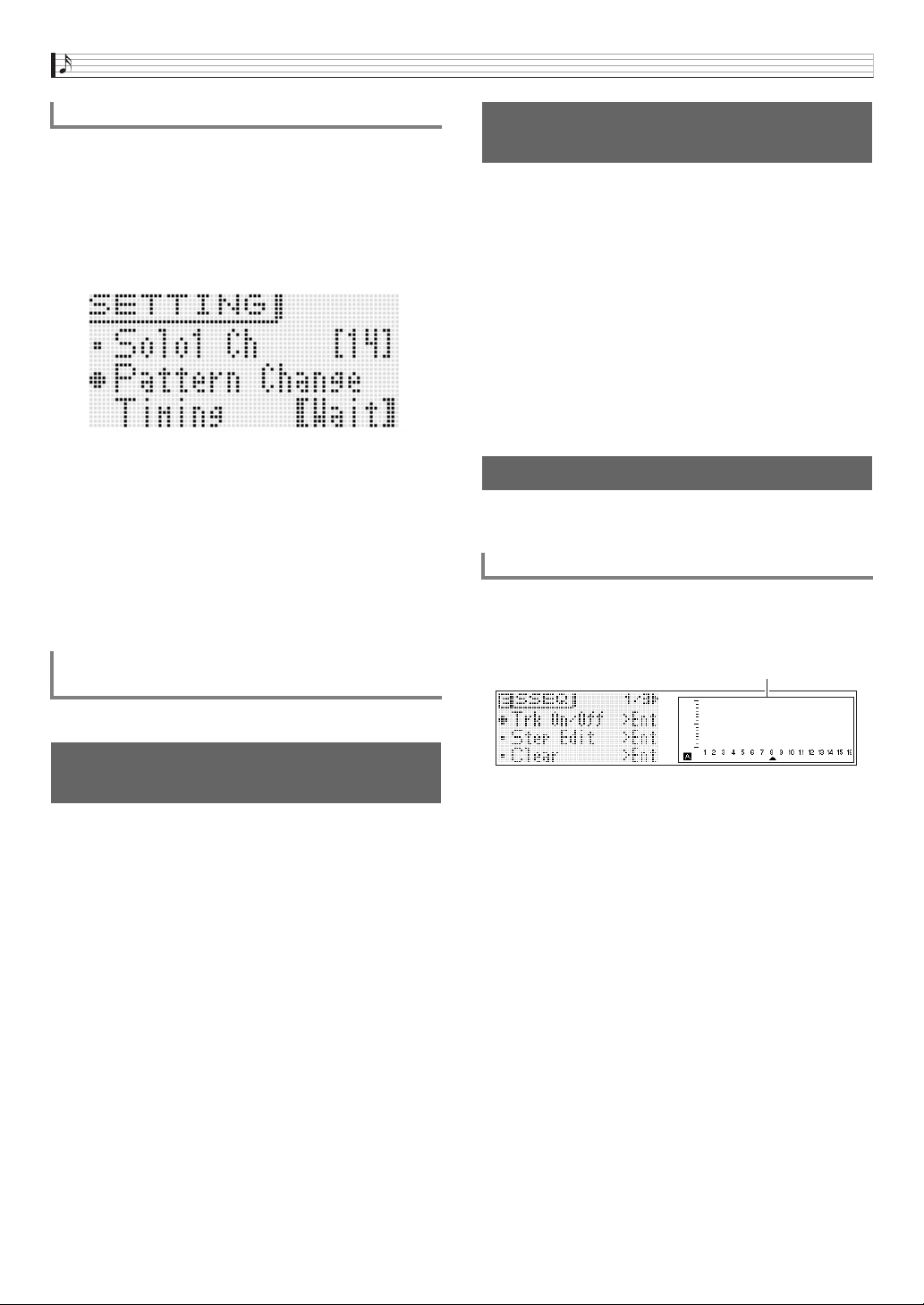
Using the Step Sequencer
E-56
1.
Perform steps 1 through 3 of the procedure
under “Changing the Solo1 Channel” on page
E-55.
2.
Use the
br
up (q) and down (w) to move the
item selection cursor (0) to “Pattern Change
Timing”.
3.
Use the
br
minus (–) and plus (+) buttons to
select one of the pattern switching timings
described below.
• The pattern switching timing setting is saved as
Performance parameter.
See “To use the Arpeggio Function” on page E-40.
You can use the Synthesizer’s mixer function to change the
Step Sequencer tone.
• Data assigned by the mixer to channels 8 through 16 is
saved as Step Sequencer data.
• Mixer parameters are applied to all pattern parameters.
• For details, see “Using the Mixer” on page E-78.
1.
Press
1
STEP SEQUENCER and then press
7
EDIT.
• This step is not necessary if you already pressed
7
EDIT and are already editing a step sequence.
2.
Press
bn
MIXER.
3.
Hold down the button (
4
9 to 16 note part
buttons) that corresponds to the part you want
to solo.
• To cancel the solo setting, exit the Step Sequencer
Mode or display the Track On/Off screen (page E-57).
• For details about mixer operations, see “Using the
Mixer” on page E-78.
You can use the procedures in this section for advanced,
detailed editing of sequence parameters.
1.
Press
7
STEP SEQ.
2.
Press
7
EDIT.
3.
Use the
br
cursor (U, q, w, I) buttons to
move the item selection cursor (0) to the menu
item for the edits you want to perform.
Changing the Timing of Pattern Switching
Wait : Wait until the start of the next measure.
Real : Switch immediately, even if it is partway through a
measure.
Beat : Switch at the beginning of the beat.
Syncing Step Sequencer Playback with an
Arpeggio
Changing the Step Sequencer
Tone
To sound a single part
(solo mode)
Editing a Sequence - Advanced
To perform advanced parameter editing
Mixer screen
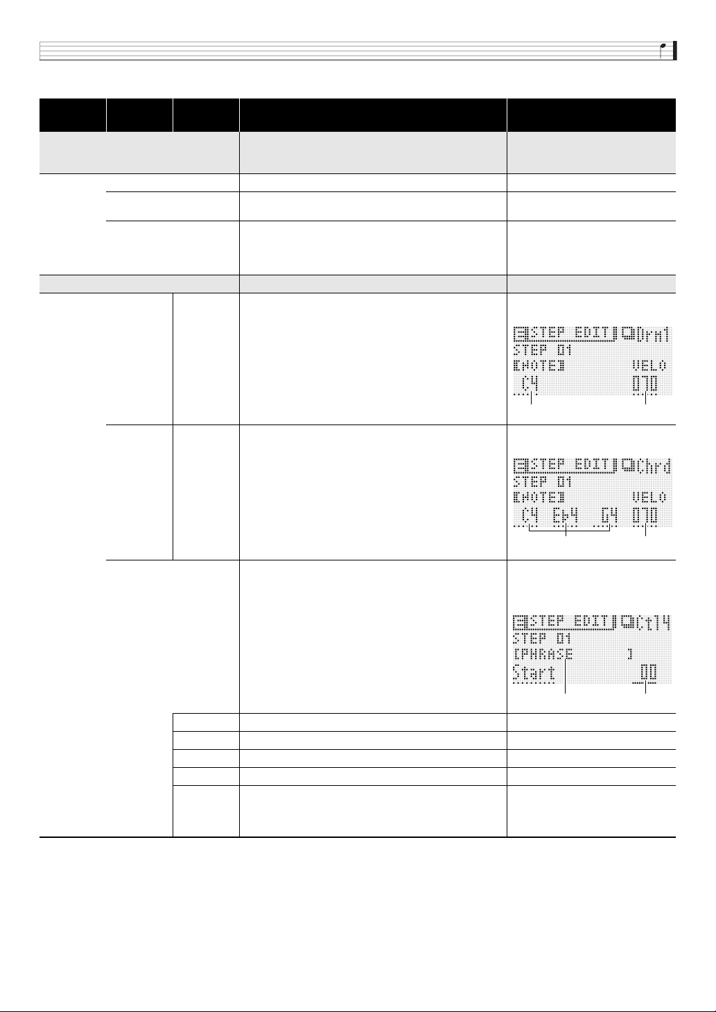
Using the Step Sequencer
E-57
■ Step Sequencer Parameters
Level 1 Level 2 Level 3 Description
Setting Range and
Screen Contents
Trk On/Off >Ent Track editing (track on/off)
•Pressing
7
EDIT while in the Step Sequencer Mode will
display the same screen as Trk On/Off >Ent.
Pattern Pattern number 1 to 8
Part Part name. Drm1 to 5, Bass, Sol1 to 2, Chrd,
Ctl1 to 4
Track Track on/off. Use
4
1 to 16 to toggle.
•
4
1 to 4 correspond respectively to Control Parts 1
through 4. In the same way,
4
8 to 16 correspond to
Note Parts (page E-51).
Off, On
Step Edit >Ent Step editing. Step-specific editing group.
Drm1 to 5,
Bass,
Sol1 and 2
NOTE, VELO Selects off (OFF), on (NOTE), or tie (TIE) for a step. When
on, note (NOTE) and velocity (VELOCITY) parameter
settings are configured. The tie setting cannot be selected
for Step 1.
Off, (When on) NOTE: C- to G9*,
(When on) VELO: 1 to 127, Tie
Chrd NOTE, VELO Selects off (OFF), on (NOTE), or tie (TIE) for a step. When
on, note (NOTE) and velocity (VELOCITY) parameter
settings are configured. The tie setting cannot be selected
for Step 1.
Off, (When on) NOTE: Off or C- to
G9*, (When on) VELO: 1 to 127, Tie
Ctl1 to 4 Control part (Ctl) effects. Data of each part. NOP: No operation. Other setting
ranges are as shown below.
Example screen shot below shows
PHRASE screen.
BEND Pitch Bender –128 to +127
CC1 to 97 MIDI control change. 0 to 127, Pan only –64 to +63
K1 to 4 Knob operations specified by a Performance, etc. 0 to 127
TEMPO Tempo 30 to 255
PHRASE Specifies triggers for starting and stopping Phrase
Sequencer playback. Display for Control 4 (Ctl4) only.
Nop: Disabled, Stop: Stop playback,
Start: Start playback,
–24 to +24: Shift from original key
(When Start is selected)
Note Velocity
Notes of chord Velocity
Menu Value
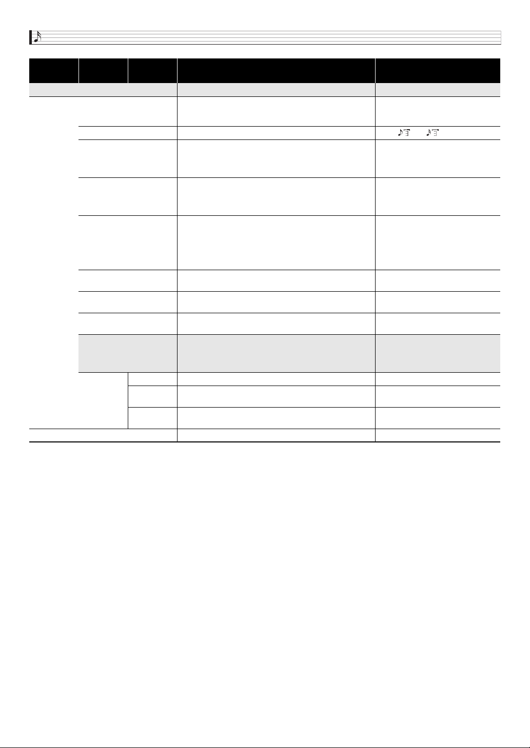
Using the Step Sequencer
E-58
Track Param >Ent Track parameter
Max Step Maximum step. Specifies the number of steps played back
by a part. If the specified maximum number of steps is
exceeded during playback, playback returns to the first step.
1 to 16
Step Size Step size. Specifies the note length between steps. 2, 6, , 7, , 8
NoteLngth Note length. Note on note length specified as a percentage
of the step size. 100% specifies the same size as the
original, while 50% specifies a note length that is half the
original.
1 to 100%
Groove Groove. Specifies the on note timing of the up beat step. The
step note length changed alternately by step playback. 50%
specifies even, while a larger value increases the first half
note length.
10 to 90%
Grv.Type Groove type. Specifies the note on note length type when
anything other than 50% is specified for Groove.
Norml: Normal Playback performed
with length based on actual
percentage.
Short: When step length is changed
by Groove, adjusts to the shorter
length.
Ctrl.Ch
(Control part only)
Control Channel. Specifies the channel that applies the
Control Track effect.
Channel 1, 8 to 16
Smooth
(Control part only)
Smooth. Controls Control Track playback. When on, control
data is interpolated and played back.
On, Off
Phrase No.
(Control part 4 only)
Phrase Sequencer number. Specifies the Phrase Sequencer
number to be controlled.
P00 to 99, U00 to 99
Key Shift >Ent Key shift editing group. This setting cannot be configured for
Control 1 through 3. Real-time setting is not supported when
Control 4 is configured to perform Phrase Sequencer key
shift.
Enable Key shift on/off Off, On
BreakPoint Point between C and B where key shift drops the octave
when the key is exceeded.
C to B
Realtime Real-time. Specifies breakpoint timing. On: Change immediately
Off: Change at the next note
Beat Info Beat setting 2/4 to 8/4, 2/8 to 16/8
Level 1 Level 2 Level 3 Description
Setting Range and
Screen Contents
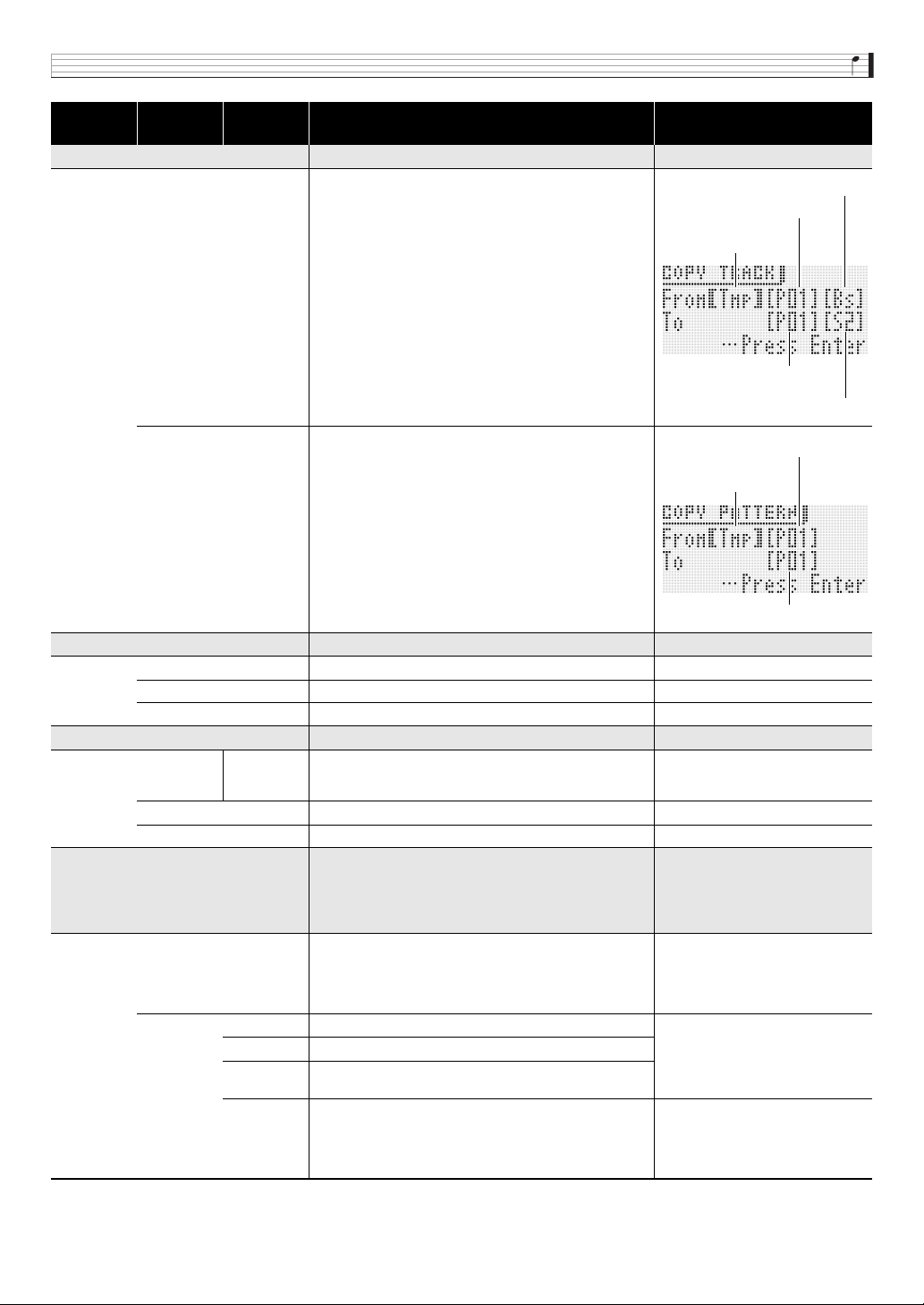
Using the Step Sequencer
E-59
* “C-” on the display indicates C-1 (one octave below C0).
Copy >Ent Data copy
Track Copies data from another track. Copies step data and part
parameter data.
• Data being edited (TMP) can also be copied.
• The following are parts that can be copied.
Pattern Copy data from another pattern.
• Data being edited (TMP) can also be copied.
Note Shift >Ent Note shift editing group
Shift Specifies how much to shift in semitone steps. –24 to +24
Ptn Specifies a pattern to be shifted. 01 to 08
Part Specifies a part to be shifted. Dr1 to 5, Bas, Sl1 and 2, Chd
Clear >Ent Track data clear
Track Pattern, Part Selects a pattern and/or part inside a track. Pattern: 01 to 16
Part: Drm1 to 5, Bass, Sol1 and 2,
Chrd, Ctl1 to 4
Pattern Clears all patterns.
Set Clears all track (set) data.
Slider Edit >Ent Step Sequencer Mode slider settings.
• When the
1
STEP SEQUENCER button is lit, you could
also hold down
2
SLIDER A/B until the “TYPE” screen
appears, and then perform the operations described
below.
TYPE
• While the “TYPE” screen is
displayed, press
br
MENU
to enter Level 3.
Changes the assigned slider function. For details about the operation
procedure and settings, see the
procedure starting from step 3 under
“Changing Slider Assignments” (page
E-54).
Copy >Ent Copies settings from another slider. For details about the operation
procedure and settings, see the
procedure starting from step 4 under
“Changing Slider Settings” (page
E-60).
Preset >Ent Scale, drum, velocity slider presets.
Note Shift
>Ent
Note shift.
M.Slider >Ent Changes the master slider function. For details about the operation
procedure and settings, see the
procedure starting from step 5 under
“Changing the Function Assigned to
the Master Slider” (page E-54).
Level 1 Level 2 Level 3 Description
Setting Range and
Screen Contents
From To
Dr1 to S2 3 Dr1 to S2
Chord 3 Chord
Ctrl1 to 3 3 Ctrl1 to 3
Ctrl4 3 Ctrl4
Copy destination pattern
number
Copy destination part name
Copy source pattern number
Copy source part name
Copy source sequence
(bank, number)
Copy destination pattern number
Copy source pattern number
Copy source sequence
(bank, number)
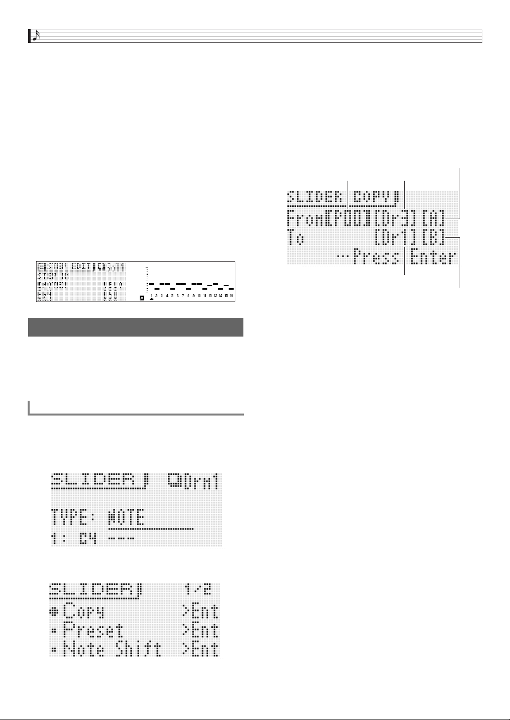
Using the Step Sequencer
E-60
4.
Use the
br
cursor (U, q, w, I) buttons to
move the brackets % or the cursor to the item
whose setting you want to change, and then
use the
br
minus (–) and plus (+) buttons to
change the selected setting.
•Use
bl
PATTERN to change the pattern number.
• Use the
9
PART minus (–) and plus (+) buttons to
change the part name.
•Use
bk
STEP minus (–) and plus (+) buttons to
change the step number.
• To return to the previous menu level, press
br
EXIT.
• The mixer screen shows current settings.
• While the Step Edit screen is displayed, the keyboard
will sound the tone of the currently selected part. The
mixer screen shows the settings of each step (the note,
velocity or value item that is currently being changed).
On the mixer screen, notes are shown in a specific
position on the screen as C through B, regardless of the
actual octave.
In addition to the changes you can make using the simple
editing procedures (page E-52), you can also do the following.
• Copy settings from another slider
• Scale, drum, velocity slider presets
• Note shift
1.
Press
1
STEP SEQUENCER.
2.
Hold down
2
SLIDER A/B until a screen like
the one shown below appears on the display.
3.
Press
br
MENU.
4.
Use the
br
cursor (U, q, w, I) buttons to
move the item selection cursor (0) to the item
you want and then press
br
ENTER. The items
available on the screen are described below.
■ Copy: Copies settings from another slider.
Use the
br
cursor (U, q, w, I) buttons to move the
brackets % to an item and then use the
br
minus (–) and
plus (+) buttons to change the item’s setting.
• Chord parts can be copied between chord parts only.
• Data being edited (!TEMP) can be specified as a copy
source.
Changing Slider Settings
To copy slider settings from another slider
SLIDER A/B button setting
Copy destination pattern name
SLIDER A/B button setting
PatternCopy source sequence number
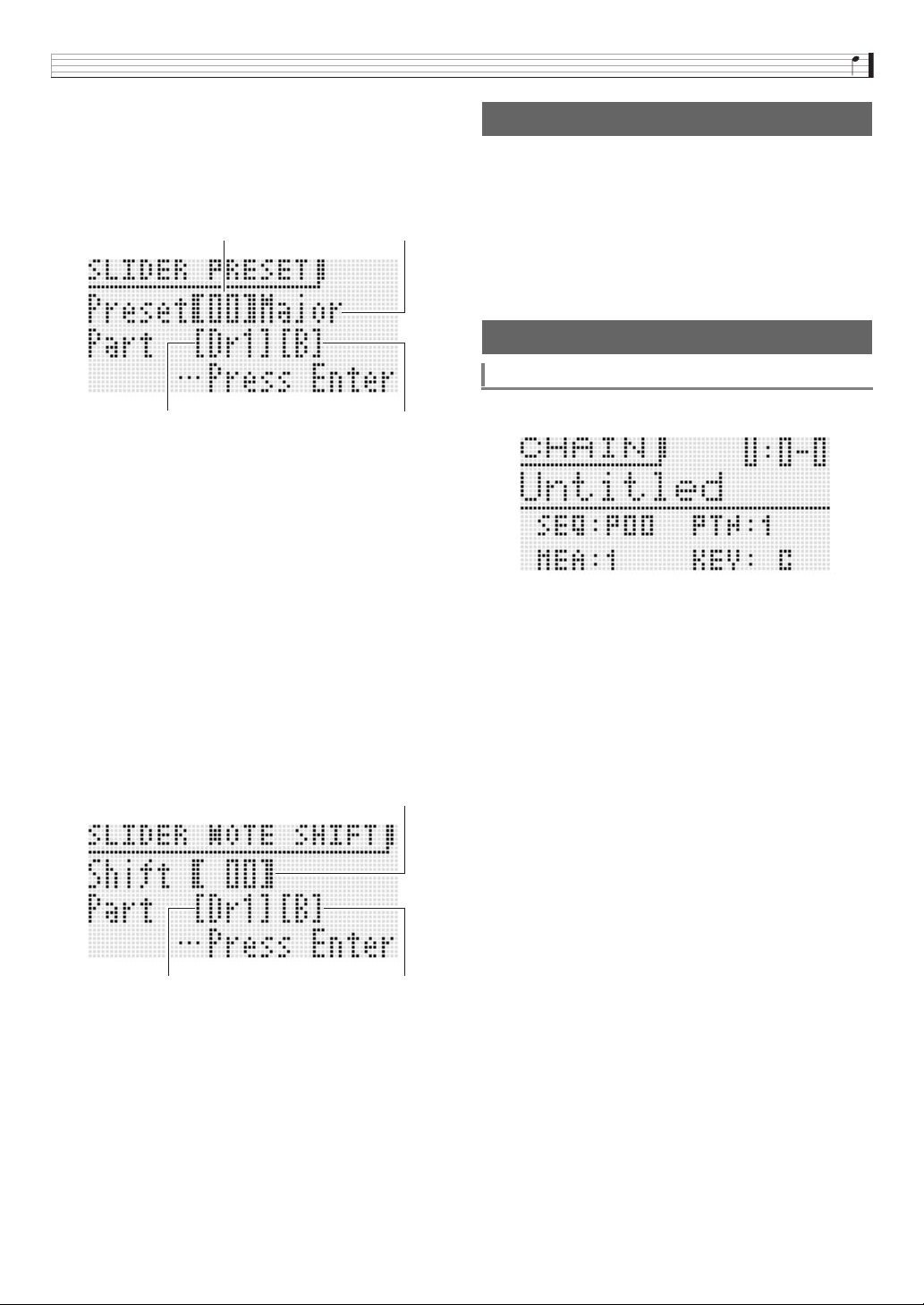
Using the Step Sequencer
E-61
■ Preset: Scale, drum, velocity slider presets
Use the
br
cursor (U, q, w, I) buttons to move the
brackets [ ] to an item and then use the
br
minus (–) and
plus (+) buttons to change the item’s setting. Inputting a
slider preset number automatically causes the slide preset
name to change accordingly.
• The following shows the slider preset numbers and their
corresponding slider preset names.
1 Major, 2 Minor, 3 Dorian, 4 Lydian,
5 Mixolydn (Mixolydian), 6 Phrygian, 7 Locrian,
8 M.Minor (Melodic Minor), 9 H.Minor (Harmonic Minor),
10 H.M. 5th (Harmonic Minor 5th), 11 Altered (Altered),
12 WholeTon (Whole Tone), 13 Diminish (Diminished),
14 Pentaton (Pentatonic), 15 M.Penta (Minor Pentatonic),
16 Blues, 17 Kick (Bass Drum), 18 Snare, 19 Hi-hat,
20 Toms, 21 Cymbal, 22 Velocity
• The following are the chord part only slider preset numbers
and their slider preset names.
1 Diatonic, 2 Minor, 3 H.Minor (Harmonic Minor), 4 Velocity
■ Note Shift: Shifts notes.
Use the
br
cursor (U, q, w, I) buttons to move the
brackets [ ] to an item and then use the
br
minus (–) and
plus (+) buttons to change the item’s shift value setting.
Press
7
WRITE to display the screen for saving a sequence.
Save the sequence by performing the same operation as that
for saving a user tone (page E-12).
• For information about deleting data you saved, see page
E-83.
■ Saving Sequences to an External Device
• Memory card (page E-86)
• Computer (page E-92)
1.
In the Step Sequencer Mode, press
bk
CHAIN.
2.
Press
7
EDIT.
Slider preset name
Pattern name SLIDER A/B button setting
Slider preset number
Shift value (–24 to +24)
Pattern name SLIDER A/B button setting
To save an edited sequence
Chaining
To create a chain
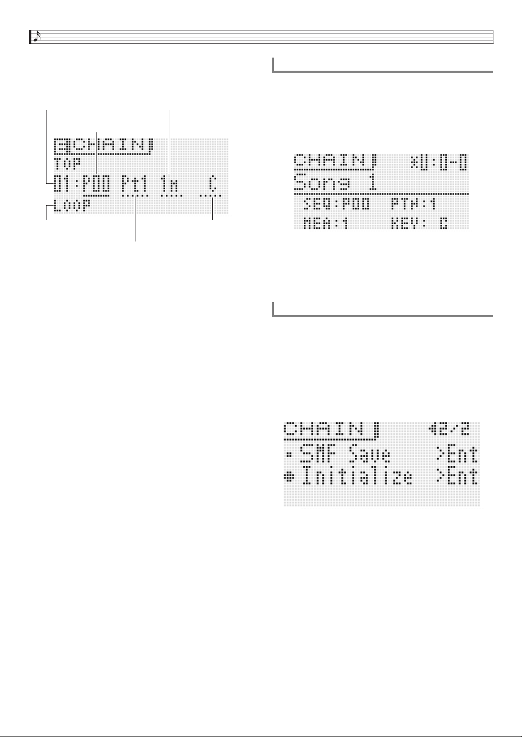
Using the Step Sequencer
E-62
3.
Use the
br
cursor (U, q, w, I) buttons to
move the cursor to an item and then input the
setting you want.
• Button operations to change a setting depend on the
item that is selected.
• For the chain type, you can specify LOOP, which loops
playback, or END to end chain playback.
• You can use
bk
DELETE to delete part of a chain.
• You also can insert part of a chain by pressing
bk
INSERT.
• To check the currently selected pattern, press
bk
CHAIN and the press
bk
START/STOP to play the
pattern. You can edit a pattern as it is playing.
4.
Press
7
WRITE to display the screen for
saving a chain. Save the chain by performing
the same operation as that for saving a user
tone (page E-12).
• For information about deleting data you saved, see
page E-83.
■ Saving a Chain to an External Device
• Memory card (page E-86)
• Computer (page E-92)
1.
Hold down
bk
CHAIN until the CHAIN screen
appears.
2.
Use the
bp
dial,
bq
buttons, or the
br
minus
(–) and plus (+) buttons to display the chain you
want to play.
3.
Press
bk
START/STOP.
• To stop playback, press
bk
START/STOP again.
• You can rearrange a chain later, if you want. For details
about how, see “To create a chain” on page E-61.
1.
Hold down
bk
CHAIN until the CHAIN screen
appears.
2.
Press
br
MENU.
3.
Use the
bp
dial or
br
cursor (U, q, w, I)
buttons to move the item selection cursor (0)
to “Initialize” and then press
br
ENTER.
4.
Press
br
ENTER again.
This should cause “Sure?” to appear on the display.
5.
Press
br
YES.
The message “Complete!” will appear on the display when
initialization is complete.
Sequence number: To select a sequence, perform
steps 2 through 5 under “To use
the Arpeggio Function” (page
E-40).
Pattern number :
br
(–, +) or
bl
PATTERN
Measure :
br
(–, +)
Key shift :
br
(–, +) or keyboard key (leftmost
keys, one octave from C to B)
Chain type :
br
(–, +)
Chain number
Chain type
Sequence number
Pattern number
Measure
Key shift
To play back a chain
To initialize chain settings
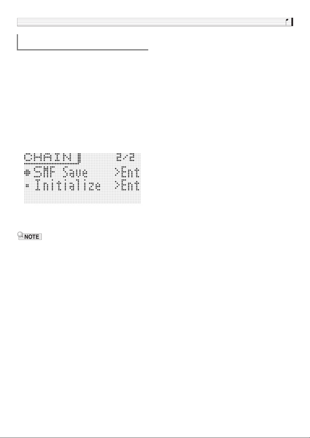
Using the Step Sequencer
E-63
• Before performing the following procedure, insert a memory
card into the Synthesizer.
1.
Hold down
bk
CHAIN until the CHAIN screen
appears.
2.
Use the
bp
dial,
bq
buttons, or the
br
minus
(–) and plus (+) buttons to display the chain you
want to save.
3.
Press
br
MENU.
4.
Use the
bp
dial or
br
cursor (U, q, w, I)
buttons to move the item selection cursor (0)
to “SMF Save” and then press
br
ENTER.
• For the remainder procedure, perform the steps starting
from step 4 under “Saving Synthesizer Data to a
Memory Card” (page E-88)
• To save data to a memory card, see “Using a Memory
Card” on page E-86.
To save a chain in SMF format to a memory
card
E-64
Recording and Playing Back with the Sample Looper
You can use the sample looper to record and loop up to
19 seconds of input from Synthesizer play, a microphone, or
line, and to overdub a previously recorded loop.
You can store up to 10 samples of recorded data in
Synthesizer memory.
• External input to the
cl
INST IN and
cl
MIC IN terminals
can be recorded as a sample. Note that input via the
cl
AUDIO IN cannot be recorded as a sample.
• To import a sample to the Synthesizer that is higher quality
than external input, use the Data Editor application
software (page E-93) to transfer wave data from a
computer.
• Sample recording can be performed using one of five
different Rec Modes, which represent different
combinations of start methods and recording types. For
details, see “To record with the sample looper” (page E-64).
• User wave editing can be used to edit parameters of a
saved sample. See “Editable Parameters for User Wave
Tone” (page E-32) for more information.
• A sample can be played back as sample looper data or as a
user wave tone on the keyboard.
• LOOP and HOLD settings can be turned on and off for
playback of samples, the same as for phrases (page E-45).
• If you want to input sound from an external source, connect
the external source to the Synthesizer as shown on page
E-8.
• You can use the Synthesizer’s pedal to perform sample
recording and playback operations. For details about
configuring pedal settings, see “Pedal” under “Editable
Performance Parameter List” (page E-73).
1.
Press
bm
REC.
This displays the LOOPER REC (sample looper
recording) setting screen. For details about the Rec
Mode, see step 2 of this procedure.
■ Rec Menu Settings
While the LOOPER REC screen is displayed, press
br
MENU to enter the Rec Menu.
•Use the
br
cursor (U, q, w, I) buttons to select
a menu item and then use the
bp
dial or the
br
minus
(–) and plus (+) buttons to change the setting of the
item.
bm
br
bp87
bk
Sample Recording
To record with the sample looper
Recording and Playing Back with the Sample Looper
E-65
• Reverse mode, sampling channel, and sampling rate settings are applied only to a new recording. They are not applied
during overdubbing.
• The higher the sampling rate, the closer the sample is to the original sound. Allowable recording time depends on the
sampling rate and channel settings.
• You can check the current threshold level and input sound level on the screen when configuring the threshold setting.
■ Adjusting the tempo
Use the
8
TEMPO minus (–) and plus (+) buttons to adjust the tempo.
• For information about the tempo adjustment method, see “To change the tempo setting” (page E-46).
2.
Use the
bp
dial and
br
minus (–) and plus (+) buttons to select one of the five Rec Modes described
below.
• The two letters at the end of the mode name indicate the method used to start recording.
• To configure the settings (Length, Beats, Splits) in each Rec Mode, use the
br
up (q) and down (w) buttons to select
an item and then use the
bp
dial or
br
minus (–) and plus (+) buttons to change the setting.
Menu Description Settings
Precount
Precount (precount). Specifies the precount inserted before recording starts when the
record start method is manual mode (ML).
Off, 2 to 8
Threshold
Threshold level (Threshold). Specifies the threshold level that must be exceeded by the
input sound to start recording when the record start method is auto mode (AT).
• Setting a large value will require a loud sound to start recording.
0 to 127
Reverse
Reverse mode (Reverse). For a new recording, plays back only the first recorded part in
reverse.
Off, On
Channel
Sampling channel (Channel). For a new recording, specifies either stereo recording or
monaural recording.
Stereo: Stereo recording
Mono: Monaural recording
Smpl Rate New recording sampling rate (sampling rate). Sampling frequency. 42 kHz, 21 kHz
Auto OVDB
Specifies the operation after the end point of a sample is set during a new recording.
Options are automatic start of loop playback (Off) or overdubbing (On).
Off, On
Channel/Rate
Approximate Maximum
Recording Time
Maximum Recordable Beats for Each Tempo
Tempo 30 Tempo 101 Tempo 120 Tempo 126 Tempo 132 Tempo 255
Stereo/42 kHz 4 seconds 2 8 9 10 10 20
Stereo/21 kHz
Mono/42 kHz
9 seconds 4 16 19 20 21 –
Mono/21 kHz 19 seconds 9 32 ––––
AT : Auto. The Synthesizer enters record standby and starts recording automatically when sound is input by playing on the
keyboard, with the microphone, etc.
ML: Manual. Recording must be started manually.
Threshold level
Input level
Recording and Playing Back with the Sample Looper
E-66
(1) NORM-AT:
Records a new sample with auto start.
• Length (recording time) setting
(2) NORM-ML:
Records a new sample with manual start.
• The settings for this mode are the same as those for
NORM-AT.
(3) BEAT-AT:
Creates a sample by recording one beat and repeating it a
specified number of times. Only auto recording is
available for this mode.
• Beats (number of beats) setting
(4) SPLT-AT:
Creates a sample by linking together recordings of a
specified number of samples, each of which is a specified
length. Only auto recording is available for this mode.
• Length (split length) setting
• Number of splits (divisions) setting
2, 3, 4, 5: Specifies the number of splits.
■ Selecting a Split Recorded with SPLT-AT as a
User Wave Tone
• To select the split as a Solo Synthesizer tone:
See “PCM Wave” (page E-23).
• To select the split as a PCM drum tone:
See “Inst Number” (page E-31).
Free : End of the sample is the point where
bm
REC or
bm
PLAY/STOP is pressed to stop
recording. If the recording reaches the
maximum allowable recording time before a
button is pressed to stop it, that point
becomes the end of the sample.
01 - 32bt : Specifies recording time as a number of
beats.
02 - 32 : Specifies the number of times a one-beat
recording is repeated.
Free : The end of the sample is when there is silence.
1 - 6bt : Specifies the number of beats to elapse before
silence, at which time recording of the next
split starts. If there is silence before the
specified number of beats is reached,
recording continues until the specified number
of beats is complete.
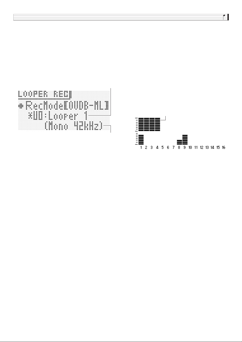
Recording and Playing Back with the Sample Looper
E-67
(5) OVDB-ML:
Enables overdubbing of an existing sample from the
beginning. Only manual recording is available for this
mode. When using this Rec Mode, you need to select the
existing sample you want to overdub before you perform
step 1 of this procedure.
The Synthesizer will automatically enter the OVDB-ML
Rec Mode immediately after you record a sample (if the
sample has not been stored yet). If you want to re-record
new data in this case, select another Rec Mode other than
OVDB-ML.
• Specifying a length that exceeds the maximum
allowable recording time will cause “ ! ” to flash on the
display. If this happens, adjust length, sampling
channel, sampling rate, tempo, and other settings in
accordance with the channel/rate indication described
on page E-65.
• Performing the operation in step 3 while an exclamation
point ( ! ) is flashing on the display will cause the
message “LOOPER: Can’t REC” to appear, indicating
that recording cannot be started.
3.
Press the
bm
REC button so it starts flashing,
which indicates record standby.
4.
Depending on the Rec Mode you selected,
perform one of the procedures described below
to start recording.
■ NORM-AT
Play something on the keyboard, input sound
from the microphone or connected electronic
music instrument, or press
bm
REC to start
recording.
• The
bm
REC button will stop flashing and remain lit
when recording starts.
• While recording is in progress, you can get a rough idea
of how much available memory has been used up by
checking the memory usage indicator on the
Synthesizer display.
• If you specified a number of beats for the “Length”
setting, the
bm
REC button will start flashing after the
specified number of beats is recorded. This indicates
that recording is in overdubbing standby.
• If you specified “Free” for the “Length” setting, pressing
bm
REC during recording to the end of the loop will
cause the
bm
REC button to start flashing. This
indicates that recording is in overdubbing standby.
• If the maximum allowable recording time is reached
during recording, recording will automatically switch to
overdubbing standby.
• As soon as recording enters overdubbing standby, the
Synthesizer starts looped playback of the sample as
recorded up to that point. During this playback you can
rehearse the next part you want to overdub, play a duet
with the loop, etc.
• If “Auto OVDB” is turned on, overdubbing will start
automatically without entering overdubbing standby.
■ NORM-ML
When you want to start recording, press
bm
REC.
• Once you start recording, procedures are the same as
those for NORM-AT.
Existing sample number and name
Sampling channel and rate
Memory usage indicator
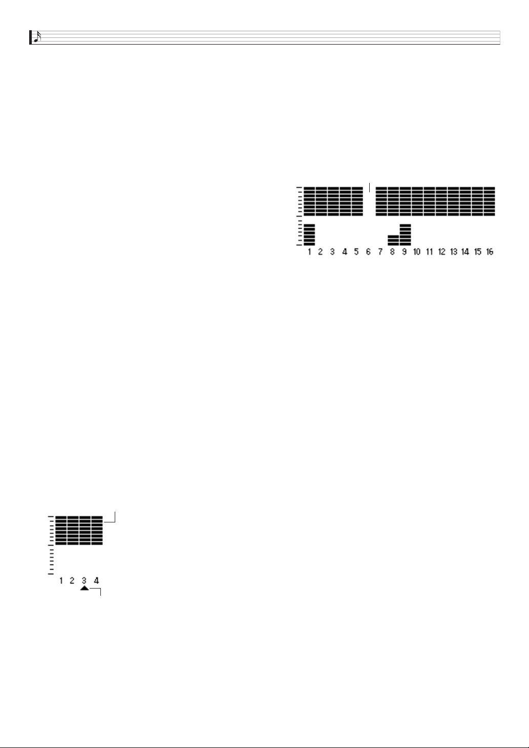
Recording and Playing Back with the Sample Looper
E-68
■ BEAT-AT
Play something on the keyboard, input sound
from the microphone or connected electronic
music instrument, or press
bm
REC to start
recording of Beat 1.
• The
bm
REC button will stop flashing and remain lit
when recording starts.
• After recording of Beat 1 is complete, the rest of the
sample from Beat 2 up to the number of beats specified
by the “Beats” setting will be created automatically.
After that, recording will enter overdubbing standby.
■ SPLT-AT
Play something on the keyboard or input sound
from the microphone or connected electronic
music instrument and recording will start
automatically.
• The
bm
REC button will stop flashing and remain lit
when recording starts.
• If you specified something other than “Free” for the
“Length” setting, recording will stop after the specified
number of beats. When the input sound becomes
silent, recording will enter standby for input of the next
sound. Recording will restart automatically when an
input sound is detected.
• If you specified “Free” for the “Length” setting,
recording will pause and standby by for further input
sound when the input sound goes silent. Recording will
restart automatically when an input sound is detected.
• The input level the Synthesizer uses for auto silence
judgment is approximately 0.5 seconds of continual
input at a level that half or less the level specified by the
Threshold setting (page E-65).
For example, if the Threshold level is set to 80,
approximately 0.5 seconds of continual level of 40 or
lower is judged to be silence.
• Recording enters overdubbing standby after the
number of recordings specified by the “Splits” setting
are complete.
• If you press
bm
REC to stop recording before the
number of splits specified by the “Splits” setting, only
the number of splits you recorded up to that point will
be saved. For example, stopping recording after three
splits when 5 is specified for the “Splits” setting will
create a loop of three splits.
■ OVDB-ML
When using the OVDB-ML Rec Mode, you need to select
the existing sample you want to overdub before you
perform step 1 of this procedure.
Press
bm
REC.
• This causes
bm
REC to light and starts overdubbing of
the sample you selected.
• During overdubbing, the Synthesizer’s display shows
the current location of the overdubbing.
• The
bm
REC button light will go out momentarily to
indicate when playback is at the beginning of the
sample.
• Overdubbing undo is not possible with the sample
looper.
5.
To restart overdubbing from overdubbing
standby, press
bm
REC.
The
bm
REC button will stop flashing and remain lit when
overdubbing starts.
• To pause overdubbing, press
bm
REC.
• Though the sample that has been recorded up to that
point continues to play as a loop, anything you play
while overdubbing is paused is not recorded.
• Press
bm
REC again to resume overdubbing.
6.
To stop recording, press
bm
PLAY/STOP.
This causes the
bm
REC button light to go out and
“!TEMP” (Temporary) to appear on the display for the
sample number.
• Even if you stop recording of a sample that contains
only silence, it is still treated as a sample.
7.
After you finish recording, save the data as
described below.
• Press
7
WRITE to display the screen for saving a
sample.
Indicates split number being recorded.
Memory usage indicator
Current overdubbing location
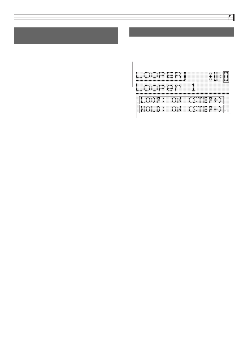
Recording and Playing Back with the Sample Looper
E-69
1.
Select the Step Sequence you want to use for
recording with the sample looper.
• For information about Step Sequencer operation, see
“Playing Back a Step Sequence” (page E-52).
2.
Press
bm
REC.
This displays the Rec Mode screen.
• Use the
br
minus (–) and plus (+) keys to change the
Rec Mode to NORM-AT.
• Configure the “Length” setting to specify the length of
your recording. For example, to specify recording of two
measures in 4/4 time, specify 8 for the “Length” setting.
3.
Press
bm
REC again.
This will enter record standby.
4.
Press
bk
START/STOP.
Step sequencer playback and sample recording start
simultaneously.
• The
bm
REC button will stop flashing and remain lit.
• After recording of the length that corresponds to the
“Length” setting you specified in step 2 is complete,
recording will enter overdubbing standby. The Step
Sequencer will also stop at this time.
• Subsequent operations from this point are the same as
those starting from step 4 under “To record with the
sample looper” (page E-64).
1.
Hold down
bm
REC until the sample selection
screen shown below appears on the display.
2.
Select the sample you want to play back.
• The procedure for selecting a sample is the same as
step 5 of the procedure for selecting an arpeggio (page
E-40).
3.
Press
bk
STEP + to toggle looping between on
and off.
• The loop setting cannot be changed if the sample is
blank.
4.
Press
bk
STEP – to toggle hold between on and
off.
• The hold setting cannot be changed if the sample is
blank.
To use the Step Sequencer to
record a sample
To play back a sample
OFF : Plays once.
ON : Repeats playback.
OFF : Playback only while
bm
PLAY/STOP is depressed.
Playback stops when the button is released.
ON : Playback starts when
bm
PLAY/STOP is pressed
and stops when
bm
PLAY/STOP is pressed again.
Sample number
Sample name
Loop setting
Hold setting
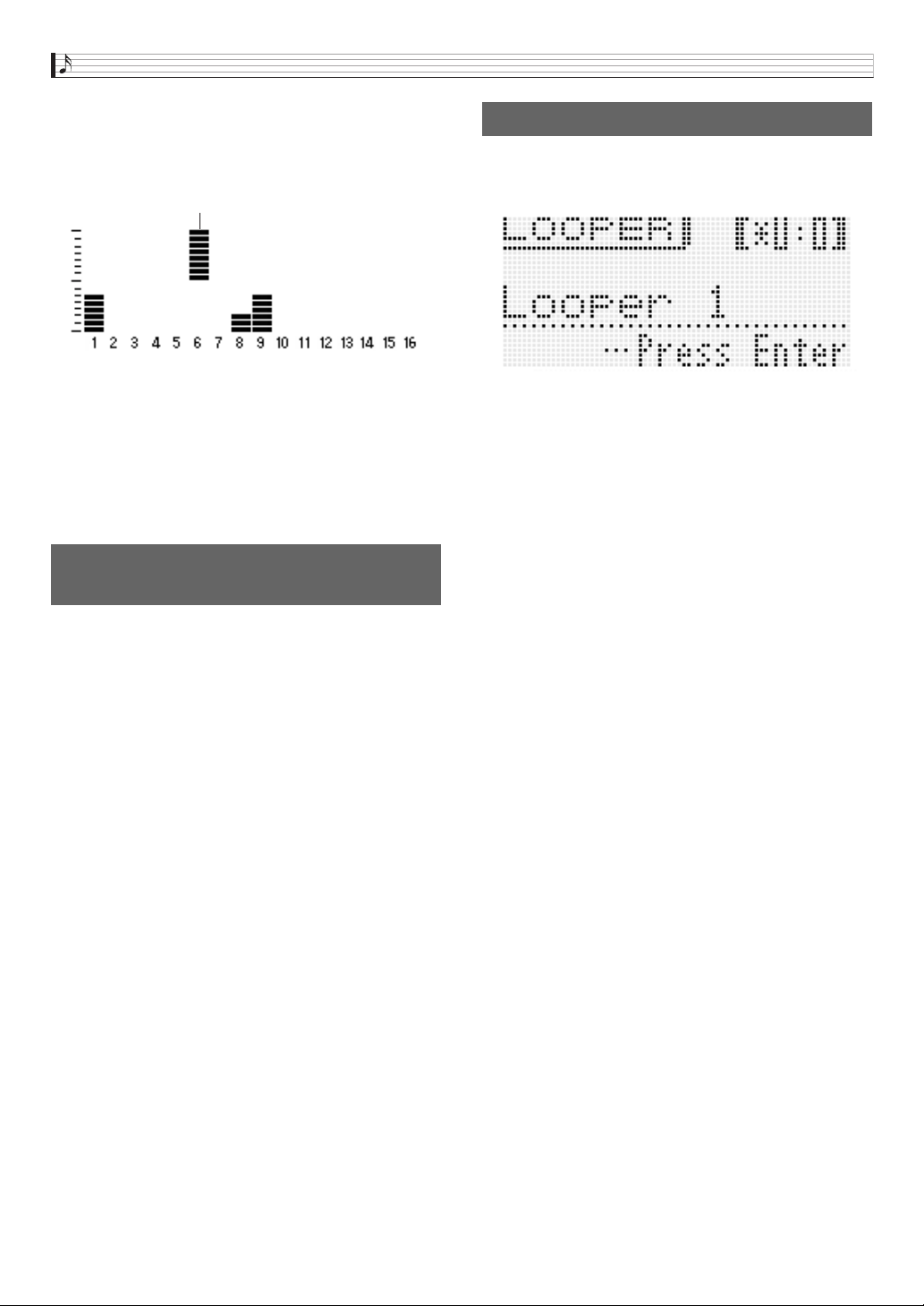
Recording and Playing Back with the Sample Looper
E-70
5.
Press
bm
PLAY/STOP to start sample playback.
• During playback, a display like the one shown below
appears, which lets you determine the current sample
playback position.
• If you perform playback with the sample selection
screen on the display, you can start overdubbing by
pressing
bm
REC.
• “LOOPER: EMPTY” is indicate on the display when
there are no samples available.
• You cannot adjust the tempo during sample playback.
6.
Press
bm
PLAY/STOP to stop sample playback.
The meanings of the indicators that are appended to the
sample number on the display are described below.
• When the currently selected sample has an exclamation
mark ( ! ) in front of its sample number or if it has !TEMP
instead of a sample number (both indicating it is unsaved),
changing the sample selection in step 2 of the procedure
under “To play back a sample” (page E-69) will cause the
unsaved sample to be discarded. To save an unsaved
sample, use the procedure under “To save a sample”,
below.
Press
7
WRITE to display the screen for saving a sample.
Save the sample by performing the same operation as that for
saving a user tone (page E-12).
• For information about deleting saved data you saved, see
page E-83.
■ Saving a Sample to an External Device
• Memory card (page E-86)
• Computer (page E-92)
Indicators Next to Sample
Numbers
! : Unsaved sample
* : Saved sample
!TEMP : Newly recorded sample that has not been saved
Current sample playback position
To save a sample
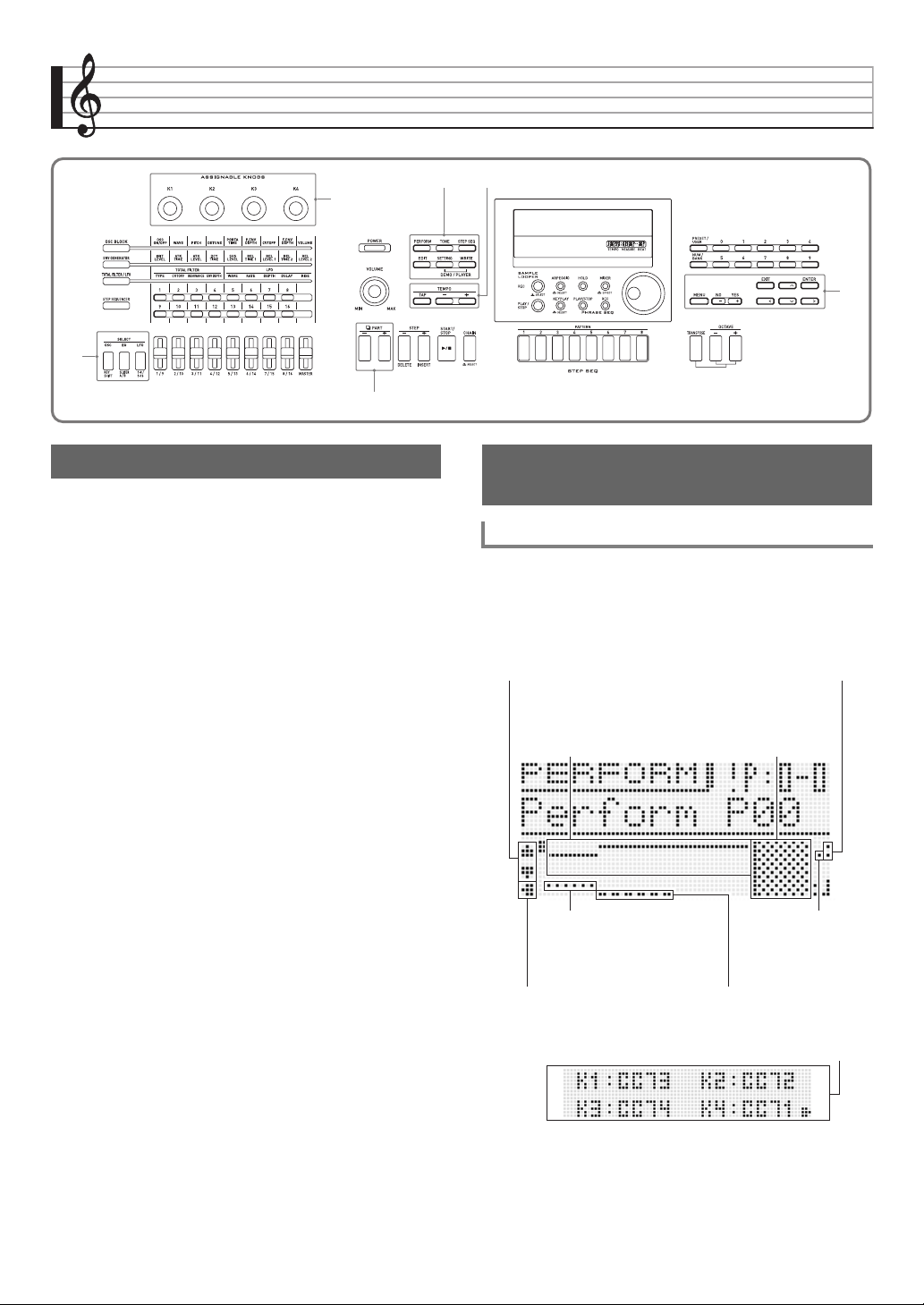
E-71
Using the Performance Mode
You can use the Performance Mode to perform with up to four
tones assigned to the keyboard. In addition to tone
assignments, you can also save effect, Step Sequencer, and
other settings as a setup (called a “performance”) which can
be recalled at any time, even while you are playing, to
instantly change the sequencer’s setup.
• There are 100 preset performances. You can edit preset
performances and save it as one of 100 user performances.
See the separate “Appendix” for a list of preset
performances.
• A different function can be assigned to each keyboard area
and applied whenever keys in its keyboard area is pressed
(Multi Function Key). For details about Multi Function Key
and about how to configure its settings, see the “Mltfunc
Key” item in the “Editable Performance Parameter List”
(page E-73).
1.
Press
7
PERFORM.
The button will light and the Synthesizer will enter the
Performance Mode.
2.
Select a performance bank and number using
the same procedure as that for selecting an
arpeggio (page E-40).
9
7
br
3
8
2
Overview Registering and Recalling
Performances
To register a performance
Press
br
left (U)
to advance to the
screen below.
3
K1 to K4 knob functions (page E-74)
Multi-function Key function
on/off status and keyboard
range setting (page E-75)
Use
br
up (q) / down (w)
to select a zone to edit
(page E-73).
Arpeggio on/off status and
keyboard range setting
(page E-75)
Phrase key play on/off status and
keyboard range setting (page E-75)
Zone Param
>Arp Enable
(page E-74)
Zone Param >Phrase Enable
(page E-74)
Zone 1 to 4 on/off and
keyboard range setting
screen (page E-73)
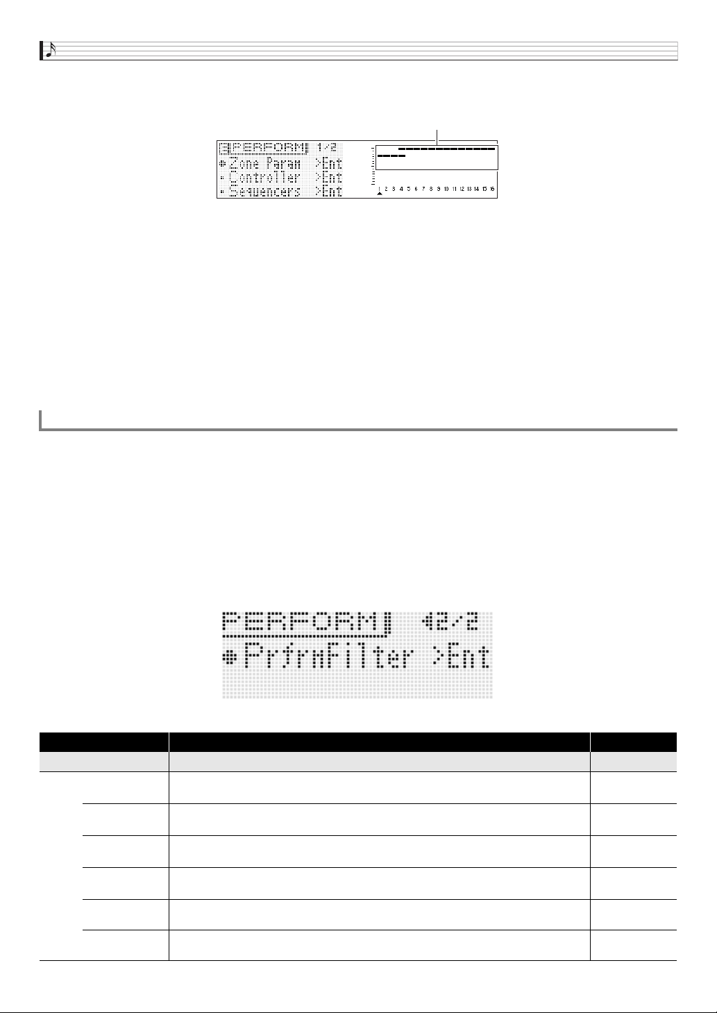
Using the Performance Mode
E-72
3.
Press
7
EDIT.
This will display the top screen of the performance editing list.
4.
Select items and change settings on the screen using the same procedures as those used when
selecting a tone.
• For details about editing, see “Editable Performance Parameter List” on page E-73.
5.
After you finish with your edits, press
7
EDIT.
This exits the editing list.
6.
Press
7
WRITE and then save your edited performance as a user performance.
• For information about how to save user data, see the procedure for saving user tone data (page E-12).
■ Saving User Performance Data to an External Device
• Memory card (page E-86)
• Computer (page E-92)
1.
Press
7
PERFORM.
The button will light and the Synthesizer will enter the Performance Mode.
2.
Select a performance bank and number using the same procedure as that for selecting an arpeggio
(page E-40).
This will recall the contents of the performance you selected.
• Recalled performance contents are the same as those described in “Editable Performance Parameter List” in the next
section of this manual.
• Here you can configure a performance filter to omit certain settings (Sequencer, arpeggio, etc.) contained in recalled
performance data. Press
br
MENU to display the performance menu. Next, select “PrfrmFilter >Ent” shown below to enter
the group and configure performance filer settings.
Performance Filter Setting List
To recall a performance
Display Description Settings
PrfrmFilter >Ent Performance filter
Step Seq
Step Sequencer on/off. Turning on this setting filters out Step Sequencer items contained in the
Sequencer Parameter group of the Editable Performance Parameter List (page E-73).
Off, On
Arpeggio
Arpeggio on/off. Turning on this setting filters out Arpeggio items contained in the Sequencer
Parameter group of the Editable Performance Parameter List (page E-73).
Off, On
Phrase
Phrase on/off. Turning on this setting filters out Phrase Sequencer items contained in the
Sequencer Parameter group of the Editable Performance Parameter List (page E-73).
Off, On
Tempo
Tempo on/off. Turning on this setting filters out Tempo settings contained in the Sequencer
Parameter group of the Editable Performance Parameter List (page E-73).
Off, On
Sys Rev
System reverb. Turning on this setting filters out reverb items contained in the Effect Parameter
group of the Editable Performance Parameter List (page E-73).
Off, On
Sys Cho
System chorus. Turning on this setting filters out chorus items contained in the Effect Parameter
group of the Editable Performance Parameter List (page E-73).
Off, On
Zone 1 to 4 on/off and keyboard range settings
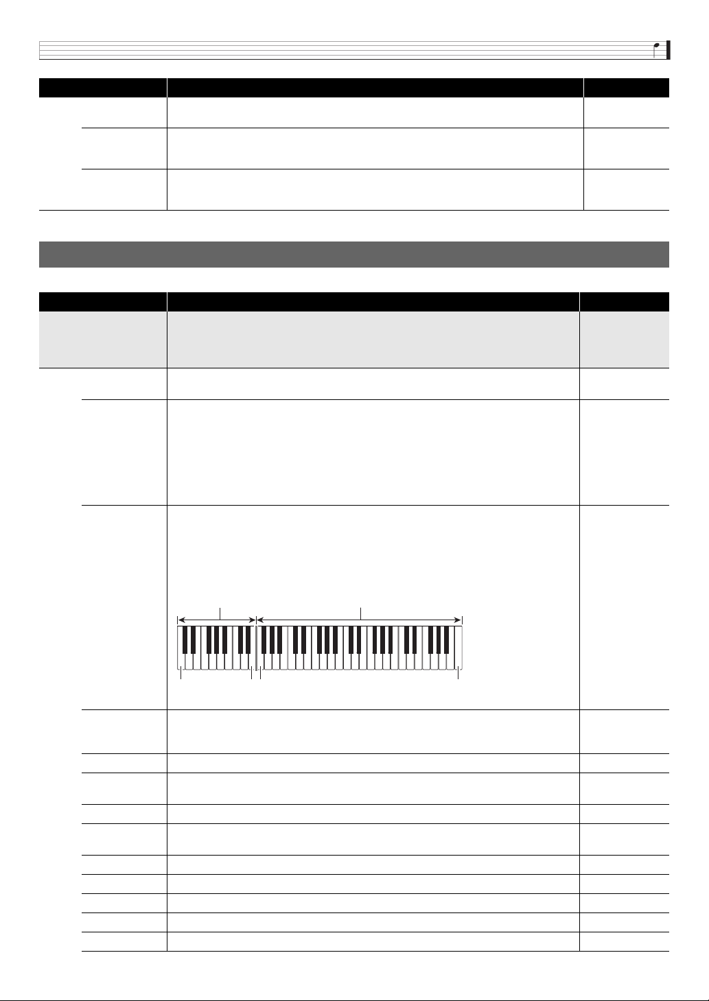
Using the Performance Mode
E-73
Editable Parameter List
Master EQ
Master Equalizer. Turning on this setting filters out master equalizer items contained in the Effect
Parameter group of the Editable Performance Parameter List (page E-73).
Off, On
Looper
Sample looper. While this setting is turned on, you will not be able to call up the sample looper
items in the Sequencer Parameter group of the Editable Performance Parameter List (page
E-73).
Off, On
Multifunc Key
Multi-function Key. While this setting is turned on, you will not be able to call up the sample looper
items in the Multi-Function Key Parameter group of the Editable Performance Parameter List
(page E-73).
Off, On
Editable Performance Parameter List
Display Description Settings
Zone Param >Ent
Zone parameters. This group includes parameters for each of the zones (Zone 1 through 4).
• Use the
9
PART minus (–) and plus (+) buttons to select the zone you want to edit.
• You also can enter the group using the following shortcut: Perform step 2 under “To register a
performance” (page E-71) and then hold down
7
EDIT. This will enter the group.
Zone
Zone on/off. Turns all zones on or off This setting is different from the mixer function page (page
E-80) part on/off (Part Enable) setting.
Off, On
Tone
Tone. Selects the tone for each zone. This setting is the same as the mixer function part tone
(page E-80).
• While this item is selected, you can select a tone using the same operation as that used in the
Tone Mode.
• This setting can also be configured using quick editing (page E-16).
• There are some limitations on the selection of tone categories for Zones 2 through 4 (page
E-16).
• A tone with DSP will have DSP next to the tone name on the display (page E-36).
Zone 1:
Solo Synth P000 to
PCM Drum U309
Zone 2 to 4:
PCM Tone P100 to
PCM Drum U309
KeyRangeLow
Key range low. Specifies the low key range of the keyboard for each zone. This setting is used in
combination with the Key Range Hi setting to configure key ranges for each zone.
For example, configuring F3 (low) to C7 (high) for Zones 1 and 2 and C2 (low) to E3 (high) for
Zones 3 and 4 will enable play of Zone 1 and 2 tones on the right side keyboard range in the
illustration below, and the Zone 3 and 4 tones on the left side keyboard.
• Setting can be specified using the keyboard keys.
C- to G9*
KeyRangeHi
Key range high. Specifies the high range of the keyboard for each zone. This setting is used in
combination with the Key Range Lo setting to configure key ranges for each zone.
• Setting can be specified using the keyboard keys.
C- to G9*
Volume Volume. This setting is the same as the mixer function tone volume (page E-80). 0 to 127
Pan
Pan. Adjusts the left-right position of sound in the stereo field. This setting is the same as the
mixer function part panning (page E-80).
–64 to 0 to +63
Oct.Shift Octave shift. Shifts the tone of notes by octave units. –2 to 0 to +2
Transpose
Transpose. Shifts the tone of notes by semitone units. This setting is the same as the mixer
function part coarse tune (page E-80).
–12 to 0 to +12
FineTune Fine tune. This setting is the same as the mixer function part fine tune (page E-80). –99 to 0 to +99
BendRngDwn Bend range down. Pitch change amount for downward bender operation. 0 to 24
BendRngUp Bend range up. Pitch change amount for upward bender operation. 0 to 24
Rev Send Reverb send. This setting is the same as the mixer reverb send (page E-80). 0 to 127
Cho Send Chorus send. This setting is the same as the mixer chorus send (page E-80). 0 to 127
Display Description Settings
C2 F3E3 C7
Zone 3
Zone 4
Zone 1
Zone 2
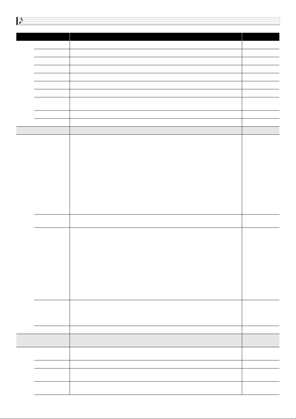
Using the Performance Mode
E-74
DSP Line DSP line. This setting is the same as the mixer function part DSP line (page E-80). Off, On
Knob1Enable Knob 1 on/off. Enables/disables
3
K1 operation for each zone. Off, On
Knob2Enable Knob 2 on/off. Enables/disables
3
K2 operation for each zone. Off, On
Knob3Enable Knob 3 on/off. Enables/disables
3
K3 operation for each zone. Off, On
Knob4Enable Knob 4 on/off. Enables/disables
3
K4 operation for each zone. Off, On
Bend Enable Bender on/off. Enables/disables
bt
BENDER operation for each zone. Off, On
Wheel Enable Modulation wheel on/off. Enables/disables
bt
MODULATION operation for each zone. Off, On
Pedal Enable
Pedal on/off. Enables/disables operation of a pedal plugged in to the
cl
SUSTAIN/
ASSIGNABLE JACK for each Zone.
Off, On
Arp Enable Arpeggio on/off. Enables/disables arpeggio function (page E-40) for each zone. Off, On
Phrase Enable Phrase on/off. Enables/disables the Phrase Sequencer (page E-45) for each zone. Off, On
Controller >Ent Controller parameters. This is group of editable parameters for controller.
K1
Knob Target 1. Selects the parameter controlled by
3
K1 knob operation. For example, if
“CC67:Soft” is specified for this setting,
3
K1 operation will apply a soft pedal effect.
CC00 to CC97: MIDI control change*
1
NRPN, RPN: MIDI NRPN and RPN parameters*
1
*
2
Ch Pressure: MIDI channel pressure*
1
Arpeggio: Preset arpeggio type (page E-40)
Tempo: Tempo setting (page E-46)
EQ Low Gain - EQ High Gain: Master EQ >Low Gain - High Gain (page E-38)
*1 For details about each setting, refer to the MIDI Implementation document
(http://world.casio.com/) and other MIDI documentation.
*2 After selecting these parameters, press
br
ENTER again and then adjust the items below.
MSB: 63H for NRPN, 65H for RPN (Setting range: 000 to 127)
LSB: 62H for NRPN, 64H for RPN (Setting range: 000 to 127)
Send Data: Specifies whether knob operation controls MSB or LSB. (Settings: MSB, LSB)
Refer to the cell to
the left.
K2 to K4
Knob Target 2 to Knob Target 4. As with K1 (Knob Target 1), Selects the parameter controlled
by
3
K2 to K4 knob operation.
Same as K1.
Pedal
Pedal. Specifies the function of the pedal plugged in to
cl
SUSTAIN/ASSIGNABLE JACK.
Hold: Pressing the pedal sustains notes. This is a sustain effect.
Soft: Pressing the pedal slightly lowers the volume of notes.
Sostenuto (Sostenut): Pressing the pedal while keyboard keys are depressed sustains (holds)
only the notes of the pressed keyboard keys.
Step Sequencer Play/Stop (SSEQ P/S): Pressing the pedal starts or stops Step Sequencer
sequence playback.
Phrase Sequencer Play/Stop (Phrase P/S): Pressing the pedal starts or stops Phrase
Sequencer phrase playback.
Phrase Record (Phrase REC): Same function as the Phrase Sequencer
bo
REC button.
Sample Looper Play/Stop (Lper P/S): Pressing the pedal starts or stops sample looper sample
playback.
Sample Looper Record (Lper Rec): Same function as the sample looper
bm
REC button.
Refer to the cell to
the left.
Touch
Touch. Specifies touch sensitivity when the keyboard is played.
Off (Off): Notes sound at a fixed volume level regardless of keyboard pressure.
Normal
Light: High-volume notes are easily produced even with light keyboard pressure.
Refer to the cell to
the left.
TchOffVel Touch off velocity. Specifies the volume level when the above touch curve setting values are off. 0 to 127
Sequencers >Ent
Sequencers parameter. This group includes Step Sequencer (page E-50), Phrase Sequencer
(page E-45), and Arpeggio function (page E-40).
Tempo
Tempo. Adjusts the Phrase Sequencer and Step Sequencer playback tempo. You also can
change the playback tempo using
8
TEMPO.
30 to 255
Step SEQ Number Step sequencer number. Specifies the Step Sequencer sequence (page E-52). Preset00 to User99
Solo1 Ch
Step Sequencer solo track part. Step Sequencer Solo Track 1 is normally Part 14, but it can be
changed to Part 1 (Zone Part 1, page E-55).
1, 14
Change
Step Sequencer change timing. Specifies the switching timing when a pattern is changed by the
Step Sequencer (page E-56).
Wait, Real, Beat
Display Description Settings
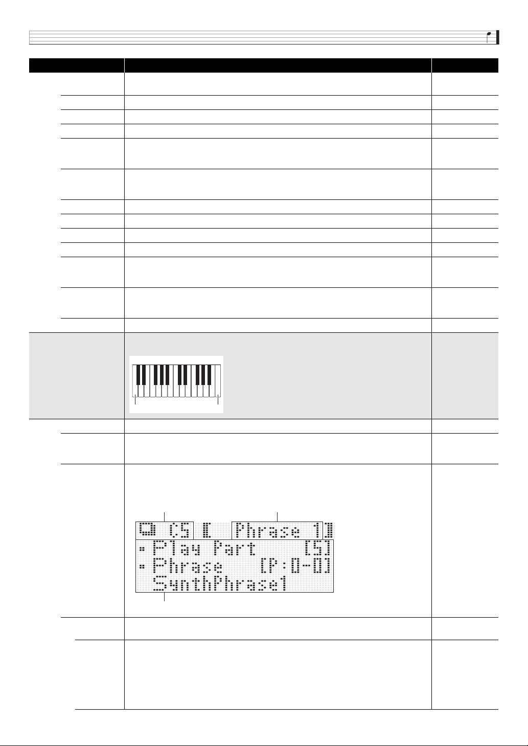
Using the Performance Mode
E-75
Key Shift
Step Sequencer key shift Switches the Step Sequencer key shift function between on and off
(page E-52).
Off, On
Pattern Step sequencer pattern number. Selects the step sequencer pattern (page E-50). 1 to 8
Arp On/Off Arpeggio on/off. The arpeggio function is disabled while this setting is off. Off, On
Arp Type Arpeggio type. Specifies the arpeggio type (page E-40). Preset00 to User99
ArpKeyRgLo
Arpeggio key range low. Specifies the low keyboard range where the arpeggio function is
enabled. This setting is used in combination with the Arpeggio Key Range Hi setting to configure
the keyboard range where the arpeggio function is enabled.
C- to G9*
ArpKeyRgHi
Arpeggio key range high. Specifies the high keyboard range where the arpeggio function is
enabled. This setting is used in combination with the Arpeggio Key Range Lo setting to configure
the keyboard range where the arpeggio function is enabled.
C- to G9*
Arp Hold Arpeggio hold on/off. Enables/disables arpeggio hold (page E-40). Off, On
Arp Synchro Arpeggio synchronization. Switches the arpeggio sync setting (page E-40). Off, On, S/S
Key Play Phrase key play. Turns Phrase Sequencer Phrase key play on or off. Off, On
Phrase Phrase number. Selects the phrase of the Phrase Sequencer (page E-45). Preset00 to User99
PhrKeyRgLo
Phrase key range low. Specifies the low keyboard range where Phrase Sequencer key play is
effective (page E-46). This setting is used in combination with the Phrase Key Range Hi setting
to specify the keyboard range where key play is enabled.
C- to G9*
PhrKeyRgHi
Phrase key range high. Specifies the effective high keyboard range where Phrase Sequencer
key play is effective (page E-46). This setting is used in combination with the Phrase Key Range
Lo setting to specify the keyboard range where key play is enabled.
C- to G9*
Looper Number Looper Number. Uses to select the sample looper sample number (page E-64). U:0 to U:9
Mltfunc Key >Ent
Multi-function Key. Assigns different functions to each keyboard area ranging from C5 to C7 (up
to 25 keys).
Enable Turns Multi-function Key on or off. Off, On
KeyRangeLow
Low keyboard range of Multi-Function Key (Multi-function Key Range Low). Specifies the lowest
keyboard range in which Multi-Function Key is applied.
• Setting can be specified using the keyboard keys.
C5 to C7
Key Setting >Ent
Function assigned to a keyboard range (Key Setting). There are two methods for specifying the
keyboard range being assigned: playing keys within the range on the keyboard and using the
9
PART minus (–) and plus (+) buttons.
---------
Indicates that the Multi-function Key function is not configured.
• Nothing will sound if “Mltfunc Key >Enable” is turned on while the function is not configured.
–
Phrase 1
Phrase 1. Specifies the playback part and performs phrase playback. Can be assigned to
keyboard range C5 to B
b
5. When Phrase 1 is configured, the Phrase 1 Stop operation can be
performed with key B5. Part 5 or Part 1 can be selected as the playback part. During playback,
the display segment at the top of Part 15 is lit. The key shift value during playback can be
specified.
• You can display the playback part mixer setting screen by pressing
bn
MIXER.
• Playback part mixer settings are saved as a performance.
• Play Part: 1, 5
• Phrase:
P:0-0 to P:9-9,
U:0-0 to U:9-9
• Key Shift:
–127 to 000 to
+127
Display Description Settings
C7C5
Function parameters
Keyboard Function
B
Using the Performance Mode
E-76
Phrase 2
Phrase 2. Specifies the playback part and performs phrase playback. Can be assigned to
keyboard range C6 to B
b
6. When Phrase 2 is configured, the Phrase 2 Stop operation can be
performed with key B6. Part 6 or Part 1 can be selected as the playback part. During playback,
the display segment at the top of Part 16 is lit. The key shift value during playback can be
specified.
• You can display the playback part mixer setting screen by pressing
bn
MIXER.
• Playback part mixer settings are saved as a performance.
• Play Part: 1, 6
• Phrase:
P:0-0 to P:9-9,
U:0-0 to U:9-9
• Key Shift:
–127 to 000 to
+127
Tempo
Tempo. Changes the tempo. When TAP is selected for this setting, the same operations as the
TAP button are performed. For other settings are selected, the tempo is changed in accordance
with the settings shown in the column to the right.
TAP, +, –,
30 to 255
Tone
Tone. When a keyboard range specified for a tone is pressed, the tone of the specified zone
changes in accordance with the Tone content.
• Zone: 1, 2, 3, 4
• Tone: Number
that can be
selected by +, –,
or “Zone Param
>Tone”
Step Seq Step Sequencer. Changes the sequence being played.
+, –,
P:0-0 to P:9-9,
U:0-0 to U:9-9
Chain Chain. Switches and turns on chains.
+, –,
U:0-0 to U:9-9
DSP
DSP. Switches the DSP. When Off, the Chorus/DSP select (page E-38) setting becomes
Chorus. However, DSP cannot be switched while a Solo Synthesizer tone is selected.
Off, +, –, ton,
P:0-0 to P:9-9,
U:0-0 to U:9-9
DSP Line DSP Line. Toggles DSP Line Select for the selected part between on and off. 01 to 16
Note
Note. Generates a note in accordance with the specified part number (Part), keyboard key (Key),
and velocity (Velocity) settings.
• Part: 01 to 16
• Key: C- to G9*
• Velocity: KeyOn,
001 to 127
Ctrl Chng
Contorol change. Generates a control change in accordance with the specified part number
(Part), control number (Control), and value (Value). When KeyOn is specified for Value, a key on
velocity value is generated. Note, however, that a 000 value is not generated when keyboard
keys are released.
• Part: 01 to 16
• Control:
000 to 119
• Value: KeyOn,
000 to 127
Prog Chng
Program Change with Bank MSB. Generates a program change in accordance with the specified
part number (Part), bank MSB (Bank MSB), and value (Value).
• Part: 01 to 16
•Bank MSB:
000 to 127
•Value:
000 to 127
Ch Press
Channel Pressure. Generates channel pressure in accordance with the specified part number
(Part) and value (Value). Channel after touch. Generates a 000 value when keyboard keys are
released.
• Part: 01 to 16
• Value: KeyOn,
001 to 127
Pitch Bend
Pitch bender. Generates pitch bender in accordance with the specified part number (Part) and
value (Value). Generates a 000 value when keyboard keys are released.
• Part: 01 to 16
• Value: KeyOn,
–256 to 000 to
255
Poly Press
Polyphonic Key Pressure. Generates pholyphonic key pressure in accordance with the specified
part number (Part), keyboard key (Key), and value (Value). Generates a 000 value when
keyboard keys are released.
• Setting can be specified using the keyboard keys.
• Part: 01 to 16
• Key: C- to G9*
• Value: KeyOn,
001 to 127
Effect >Ent
Effect parameter. This group includes effect settings (page E-37). For details about group items,
see “Effect Settings” (page E-38).
MIDI >Ent
MIDI parameters. This group includes MIDI parameter (page E-82) settings. Use the
9
PART
minus (–) and plus (+) buttons to select one of the Synthesizer’s 16 sound source parts for
editing.
Ext Out Ch
External Out Channel. Specifies the MIDI send channel for sending information about each part
to an external destination (page E-82).
1 to 16
Ext In Ch External in channel. This is the MIDI message channel received by each part. Off, 1 to 16
Gen Out
Internal send on/off. Specifies whether or not the information of each part is sent to the
Synthesizer’s sound source.
Off, On
Display Description Settings
B

Using the Performance Mode
E-77
* “C-” on the display indicates C-1 (one octave below C0).
MIDI Out
MIDI output on/off. Specifies whether or not MIDI send of the information of each part is
performed from
ck
MIDI OUT/THRU.
Off, On
USB Out
USB output on/off. Specifies whether or not MIDI send of the information of each part is
performed from
ck
USB.
Off, On
Display Description Settings
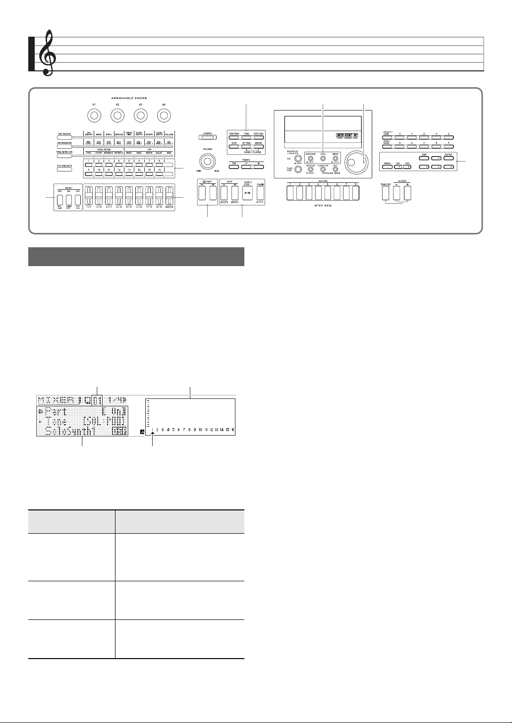
E-78
Other Useful Functions
The mixer lets you make adjustments to the tone, volume
level, and other settings* of the Synthesizer’s sound source
parts (Parts 01 through 16, external input parts, page E-18),
while viewing the balance between the parts on the display.
* Settings that affect individual parts are called “part
settings”, wile settings that affect all parts are called
“master settings”.
1.
Press
bn
MIXER.
This displays the mixer screen.
2.
Use the
9
PART minus (–) and plus (+) buttons
to select the part whose settings you want to
configure.
3.
Use the
br
cursor (U, q, w, I) buttons to
select the item you want, and then use the
bp
dial or
br
minus (–) and plus (+) buttons to
change its setting.
• For details about settings, see “Mixer Settings” on page
E-80
4.
After settings are the way you want, press
bn
MIXER to exit the mixer screen.
9
7
bn
bp
br
5
bk
4
2
Using the Mixer
To perform this
adjustment:
Select this part:
Individual settings (page
E-80) of parts 01 through
16
All, 01 to 16
• “All” can be selected to batch adjust all
parts from 01 through 16. To select
“All”, press the
9
PART minus (–)
button once while “01” is displayed.
Master settings (page
E-80)
Master
• To select “Master”, press the
9
PART minus (–) button twice while
“01” is displayed.
External input part
settings (page E-80)
Ext
• To select “Ext”, press the
9
PART
minus (–) button three times while
“01” is displayed.
Part being configured Current part setting
Setting item list Indicates part being configured
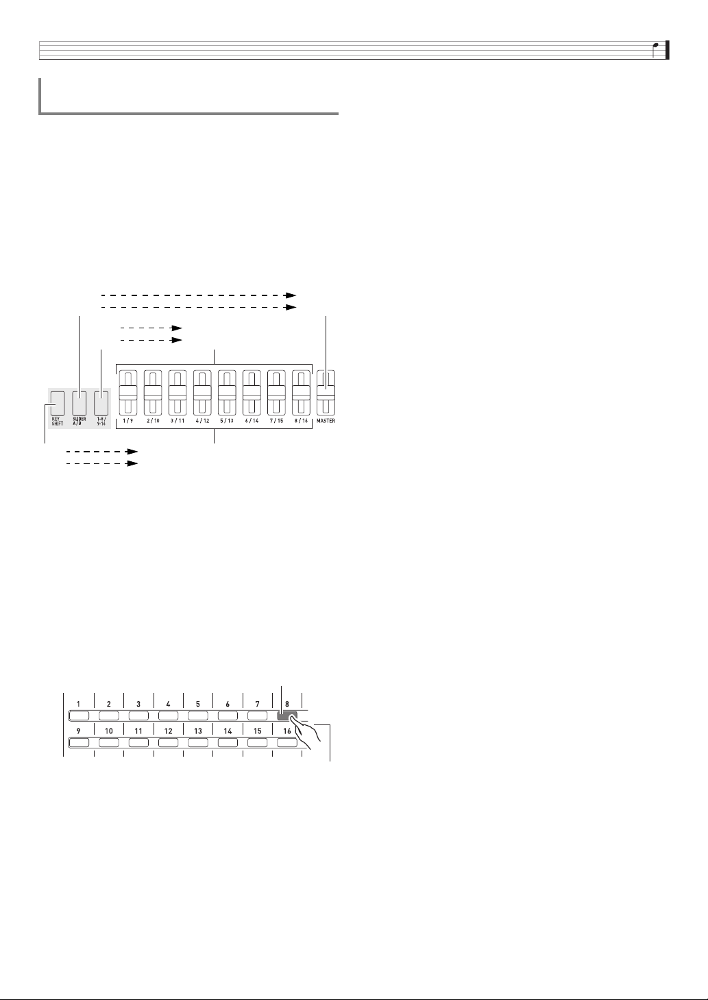
Other Useful Functions
E-79
You can use the
5
1/9 to MASTER sliders and the
4
step
(1 to 16) buttons to make instant changes in mixer settings.
1.
Press
bn
MIXER.
This displays the mixer screen.
2.
Use the
2
KEY SHIFT, SLIDER A/B, and 1-8/
9-16 buttons to change the part assigned to the
5
1/9 to MASTER sliders.
• Each press of one of the above buttons toggles the
button between being lit and unlit.
3.
Move a slider to adjust the setting of the part
assigned to it.
• Use the
br
cursor (U, q, w, I ) buttons to select a
setting item.
4.
Use the
4
1 to 16 buttons to toggle parts 01
through 16 between on and off.
• Each press of a button toggles it between lit (on) and
unlit (off).
• Holding a button down will turn that part on and turn all
other parts off (solo mode). Press the same button
again to exit the solo mode.
Example: To enter the solo mode for Part 08
Instant Adjustment of Settings using the
Sliders and Step Buttons
2
Unlit
Lit
Master
Ext
Unlit
Lit
Part 01 - 08
Part 09 - 16
Unlit
Lit
Part 01 through 08 (or 09 through 16)
All parts (leftmost slider only)
4
Lit
Hold down for a short while.
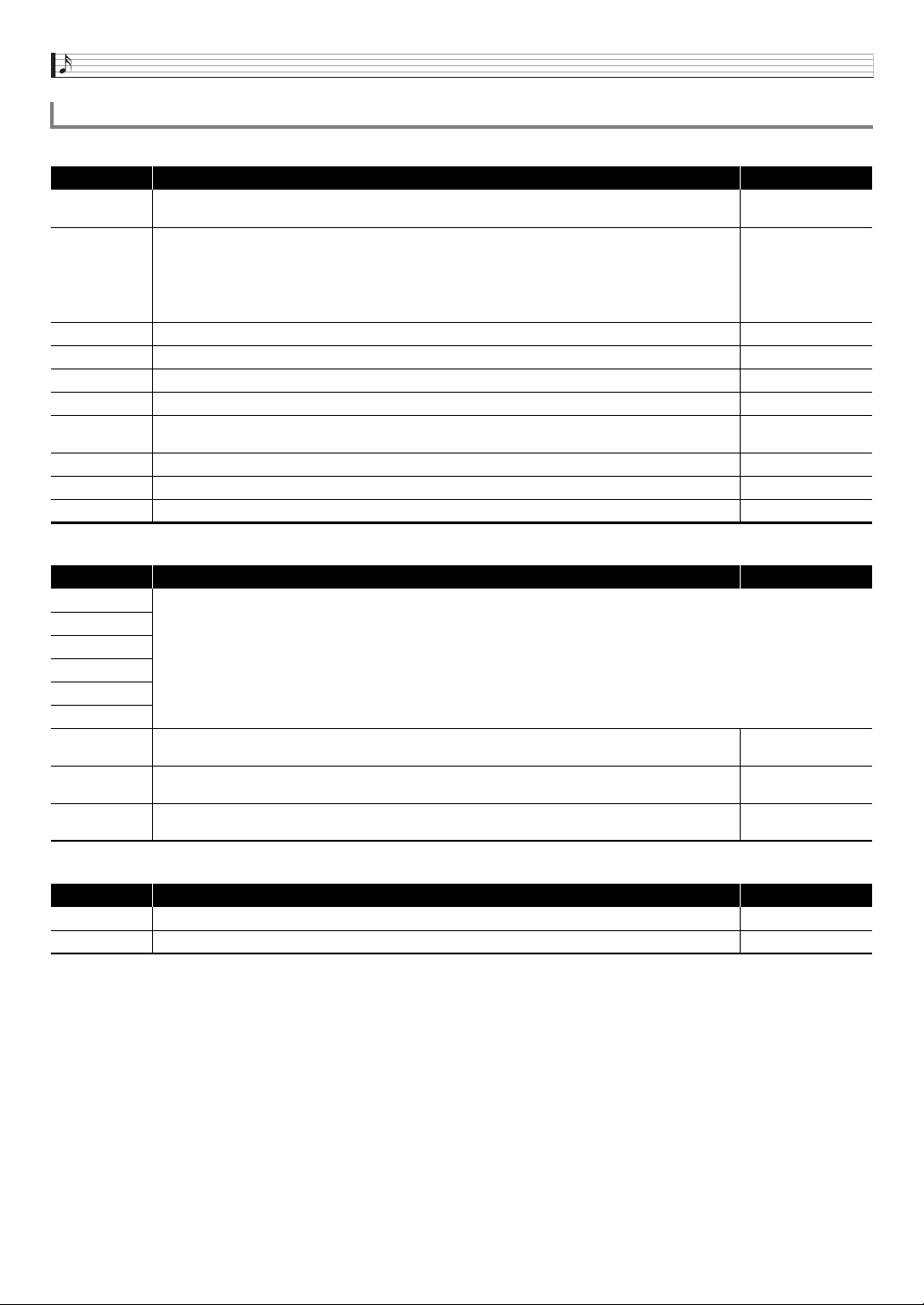
Other Useful Functions
E-80
■ Part 01 through Part 16 Settings
■ External Input Part Settings
■ Master Settings
Mixer Settings
Display Description Settings
Part
Part on/off. Turns each part on or off. This is the same parameter that is turned on and off by the
4
1to16 buttons (page E-79).
Off, On
Tone
Part tone. This is the tone of each part.
While this item is selected, you can select a tone using the same operation as that used in the Tone
Mode.
• A tone with DSP will have DSP next to the tone name on the display (page E-37).
Part 01:
Solo Synth P000 to
PCM Drum U309
Part 02 to 16:
PCM Tone P100 to
PCM Drum U309
Volume Part volume. This is the volume of each part. 0 to 127
Pan Part panning. Adjusts the left-right position of sound in the stereo field. –64 to 0 to +63
CoarseTune Part coarse tune. Shifts the pitch of notes by semitone units. –12 to 0 to +12
FineTune Part fine tune. Shifts the pitch of notes by cent units. –99 to 0 to +99
BendRange
Part bend range. Specifies (in semitone units) the maximum change in pitch when the
bt
BENDER
wheel is rotated.
–24 to 0 to +24
DSP Line Part DSP line. Specifies whether DSP (page E-36) is applied to the notes of each part. Off, On
Rev Send Part reverb send. Controls how the reverb effect (page E-36) is applied to each part. 0 to 127
Cho Send Part chorus send. Controls how the chorus effect (page E-36) is applied to each part. 0 to 127
Display Description Settings
Part
Same as “Part 01 through Part 16 Settings” (page E-80).
Volume
Pan
DSP Line
Rev Send
Cho Send
N.Thresh
Noise gate threshold. Reduces noise by cutting all input sound at a volume that is smaller than this
setting value.
0 to 127
N.Release
Noise gate release. Time that input sound is cut after its volume drops below the noise gate threshold
value.
0 to 127
Auto Level
Auto level control. Automatically adjusts the input signal level. The greater the setting value, the stronger
the effect.
Off, 1 to 3
Display Description Settings
Volume Master volume. Adjusts the volume of all the parts. 0 to 127
Pan Master panning. Adjusts the left-right position of sound in the stereo field of all the parts. –64 to 0 to +63
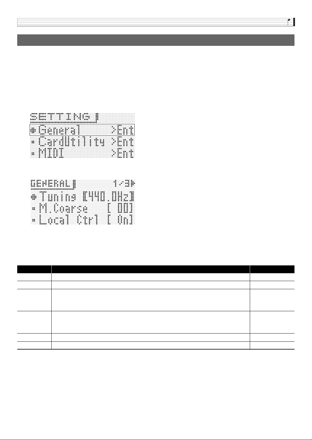
Other Useful Functions
E-81
The following are Synthesizer settings that can be configured globally.
• Tuning (Fine tuning of note pitch)
• Local Control
• Master Coarse Tune (Tuning of note pitch in semitone steps)
• Initial Power On Mode
• Display Contrast
• Auto Power Off On/Off (page E-10)
1.
Press
7
SETTING.
This displays the setting screen with “General >Ent” selected.
2.
Press
br
ENTER.
3.
Use the
br
cursor (U, q, w, I) buttons to select the item you want, and then use the
bp
dial or
br
minus (–) and plus (+) buttons to change its setting.
Settings
4.
After settings are the way you want, press
7
SETTING to exit the setting screen.
Global Synthesizer Settings
Display Description Settings
Tuning Tuning. Fine tuning of Synthesizer pitch in 0.1 Hertz steps. 415.5 to 465.9 Hz
M.Coarse Master coarse tune. Adjustment of overall Synthesizer pitch in semitone units –24 to 0 to +24
Local Ctrl
Local control. Turning off local control disables the Synthesizer’s internal sound source, so nothing sound
when keyboard keys are pressed. Turn off local control when you want to use the Synthesizer keyboard
and pedal operations to operate an external sound source, without producing any sound from the
Synthesizer itself.
Off, On
Start Up
Start up item. Specifies one of the following as the Synthesizers initial power on mode.
Perfm: Performance Mode
Tone: Tone Mode
S.Seq: Step Sequencer Mode
Refer to the cell to the
left.
Contrast Display contrast. Adjusts the contrast of the display. 1 to 17
Auto Power Auto Power Off function on/off. Turning off this setting disables Auto Power Off (page E-10). Off, On
Other Useful Functions
E-82
The letters MIDI stand for Musical Instrument Digital Interface, which is the name of a worldwide standard for digital signals and
connectors that makes it possible to exchange musical data between musical instruments and computers (machines) produced by
different manufacturers.
For details about the MIDI specifications of this Synthesizer, see the “MIDI Implementation” document at the website located at the
URL below.
http://world.casio.com/
• Use a separately available or commercially available MIDI cable to connect the MIDI terminals of your Synthesizer and another
electronic musical instrument for exchange of MIDI data (page E-8).
• For information about connecting a computer, see page E-92.
• For information about the relationship between each Synthesizer part (page E-78) and the MIDI IN and MIDI OUT channels, see
“Editable Performance Parameter List” (page E-73).
• This Synthesizer conforms to General MIDI Level 1 (GM).
1.
Press
7
SETTING.
2.
Use the
br
down (w) button to select “MIDI >Ent” and then press
br
ENTER.
3.
Use the
br
cursor (U, q, w, I) buttons to select the item you want, and then use the
bp
dial or
br
minus (–) and plus (+) buttons to change its setting.
Settings
Using MIDI
What is MIDI?
MIDI Settings
Display Description Settings
Device ID
Device ID. Selects the ID number of the Synthesizer for MIDI system exclusive message send/receive.
• While “All” is selected, a system exclusive message is sent regardless of the ID number.
• For details about the ID number, see MIDI Implementation at
http://world.casio.com/.
1 to 16, ALL
Basic Ch
Basic channel. Specifies the receive channel of “Perform NRPN”, “S.Seq NRPN”, and other MIDI
messages described below.
1 to 16
MIDIOutSel
MIDI OUT select. Specifies what is output as MIDI OUT.*
KEY (Keyboard): Synthesizer keyboard play, operations, etc.
MIDI (MIDI IN): Messages input via
ck
MIDI IN (MIDI THRU)
USB (USB IN): Messages input via
ck
USB
Refer to the cell to the
left.
USBOutSel
USB out select. Specifies what is output as USB out.*
KEY (Keyboard): Keyboard and other Synthesizer operations
MIDI (MIDI IN): Messages input via
ck
MIDI IN
Refer to the cell to the
left.
MIDI In
MIDI IN on/off (MIDI IN enable). While this setting is turned on, messages input via
ck
MIDI IN are
reflected by the Synthesizer’s internal sound source.
Off, On
USB In
USB IN on/off (USB IN enable). While this setting is turned on, messages input via
ck
USB are reflected
by the Synthesizer’s internal sound source.
Off, On
Sync Mode
Sync mode. Settings for MIDI syncing between the Synthesizer and an external device.*
Off: No syncing
Mast (Master): Outputs Clock, Start/Stop (Step Sequencer), and other signals from the Sequencer to
control an external device.
Slav (Slave): Receives Clock, Start/Stop, and other signals from an external device.
• Step Sequencer and Phrase Sequencer playback is not possible unless Clock is received. Start/Stop is
interpreted as Step Sequencer start/stop.
Refer to the cell to the
left.
Perform NRPN
Performance NRPN change.
When this setting is turned on, a Synthesizer performance (page E-72) can be selected by a MIDI NRPN
message from an external device.
Off, On
S.Seq NRPN
Step Sequencer NRPN change. When this setting is turned on, a Synthesizer sequence (page E-52) can
be selected by a MIDI NRPN message from an external device.
Off, On
Phrase NRPN
Phrase NRPN change. When this setting is turned on, a Synthesizer phrase (page E-45) can be selected
by a MIDI NRPN message from an external device.
Off, On
Other Useful Functions
E-83
* To apply setting changes, turn the Synthesizer off and then back on again. A message to that effect appears on the display
whenever you exit a setting screen.
4.
After settings are the way you want, press
7
SETTING to exit the setting screen.
• You can also use performance data editing to change the MIDI data send channel and configure other settings. For more
information, see the “MIDI >Ent” group (page E-76).
You can use the procedure below to delete user tones, user sequences, and other data that you created.
1.
Referring to the table in step 2 of the procedure under “To save Synthesizer data to a memory card”
(page E-88), perform the procedure required for the type of data you want to delete.
2.
Use the
br
up (q) and down (w) buttons to move the item selection cursor (0) to “Clear USER” and
then press
br
ENTER.
• This causes a menu screen like the one shown below to appear on the display. The sample screen below shows the screen
that appears when you perform this procedure from the Step Sequencer Mode.
• In the case of the Phrase Sequencer, the phrase data size is also displayed.
3.
Use the
bp
dial or
br
minus (–) and plus (+) buttons to select the user data you want to delete.
4.
Press the
br
ENTER button.
5.
In response to the “Sure?” message that appears, press the
br
YES button to delete or the
br
NO
button to cancel.
Arp NRPN
Arpeggio NRPN change. When this setting is turned on, a Synthesizer arpeggio type (page E-40) can be
selected by a MIDI NRPN message from an external device.
Off, On
Deleting Data Saved on the Synthesizer
Display Description Settings
Other Useful Functions
E-84
You can use the procedure below to return the Synthesizer’s
settings and data to their initial defaults.
1.
Press
7
SETTING.
2.
Press
br
ENTER.
3.
Use the
br
cursor (U, q, w, I) buttons to
select “Initialize >Ent” and then press
br
(ENTER).
This will display the INITIALIZE screen.
4.
Use the
br
up (q) and down (w) buttons to
select the initialization option you want.
Initialization Options
5.
Press
br
ENTER.
This should cause “Sure?” to appear on the display.
6.
Press
br
YES.
The message “Complete!” will appear on the display when
delete is complete.
7.
Press
7
SETTING to exit the setting screen.
• You can visit the CASIO website
(http://world.casio.com/) to download the Synthesizer’s
factory default settings and data, and transfer it to the
Synthesizer, if you want.
To connect to a computer, see “Connecting to a
Computer” (page E-92).
You can use the procedure below to play back the
Synthesizer built in demo tunes, and to play back SMF
(Standard MIDI File) music files on a memory card.
1.
Press
7
SETTING and
7
WRITE at the same
time.
2.
Use the
br
up (q) and down (w) buttons to
select the type of playback you want to perform.
Auto Playback Types
Initializing Synthesizer Global
Settings and Data
Display Description
Parameter >Ent Parameters only. Initializes all Synthesizer
settings except for display contrast (E-81).
All >Ent All settings and data. Returns all Synthesizer
settings and data to their initial defaults. Also
deletes user waves.
Playing a Demo Tune or a File
from a Memory Card
Display Description
Demo >Ent
Demo Tune (Demo). For playback of the
Synthesizer’s built-in demo tunes.
Smf >Ent
SMF (Standard MIDI File) music files. For
playback of SMF music files from a memory card
loaded in the Synthesizer’s card slot.
• Supported playback music files formats are SMF
format 0 and 1 MIDI files (MID).
• Make sure that the data you want to play is in the
MUSICDAT folder (page E-89) on the memory
card.
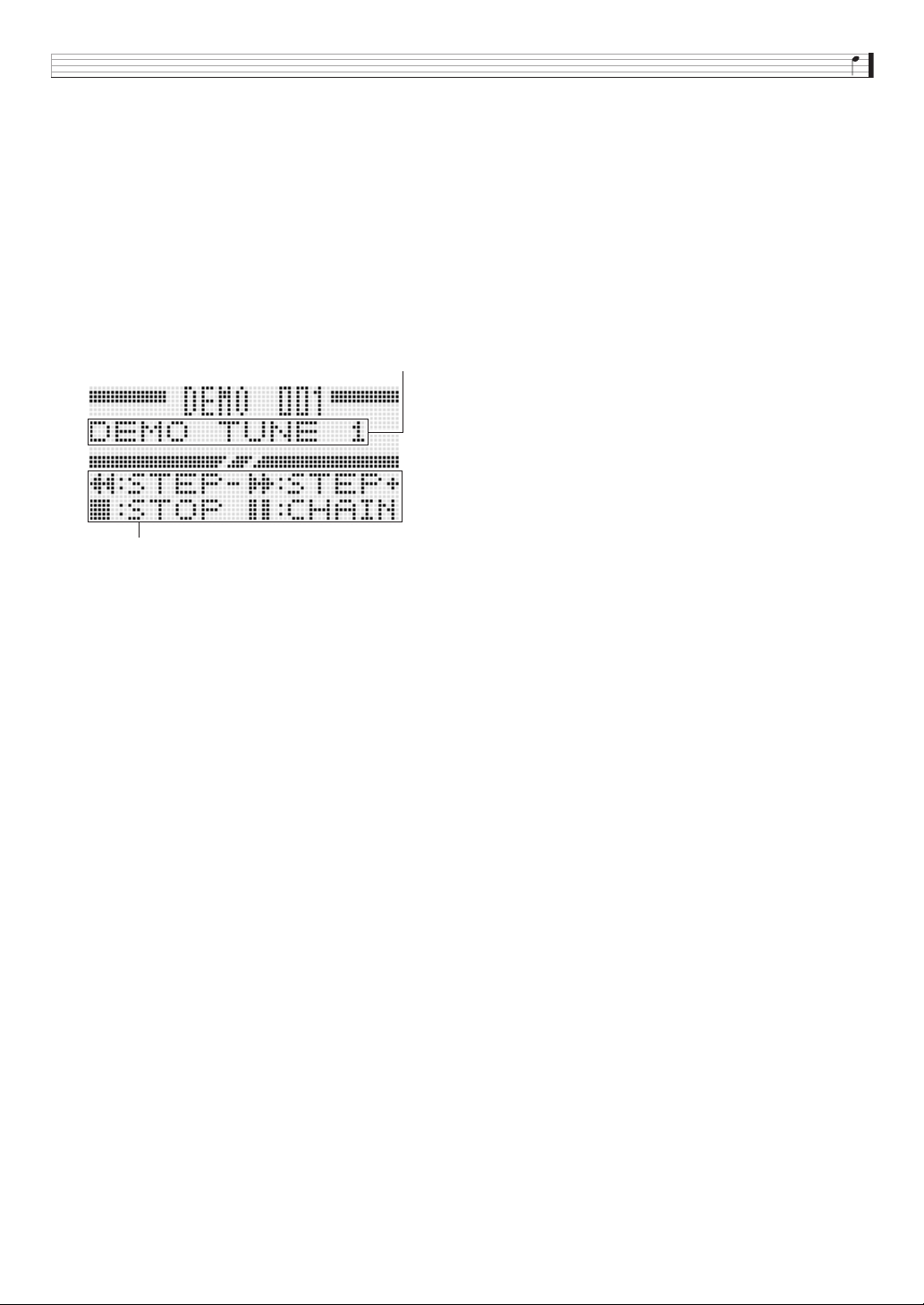
Other Useful Functions
E-85
3.
Press
br
ENTER.
This displays the playback screen.
• In the case of a demo tune, playback will start
automatically. In the case of an SMF music file, use the
br
minus (–) and plus (+) buttons to select a file and
press
bk
START/STOP to start playback.
• While playback is in progress, you can use the
bp
dial
or
br
minus (–) and plus (+) buttons to change to a
different tune or file for playback.
You also can use the four
bk
buttons to perform fast
forward and other playback operations as shown
below.
Demo Tune Playback Screen
4.
Press
bk
START/STOP.
This stops playback and exits the playback screen.
• You also can stop playback by pressing the
7
SETTING and WRITE buttons at the same time or by
pressing
br
EXIT.
Tune name
Operation Guide
s (Fast Reverse) :
bk
STEP –
d (Fast Forward) :
bk
STEP +
Y (Stop) :
bk
START/STOP
k (Pause) :
bk
CHAIN
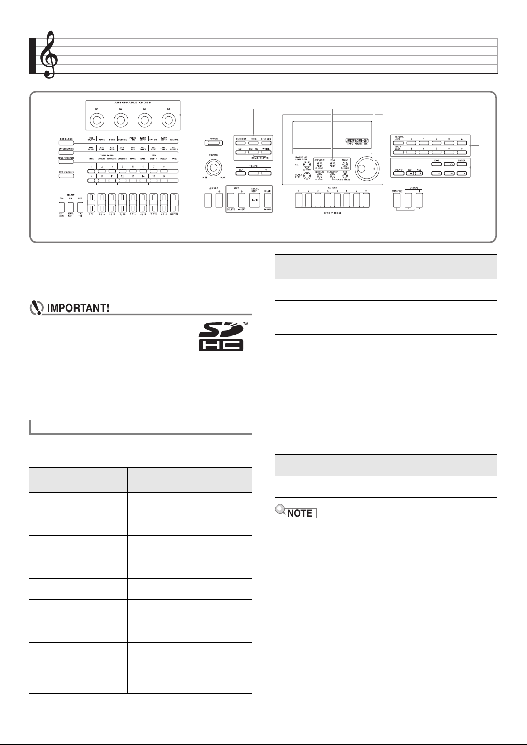
E-86
Using a Memory Card
You can save Synthesizer user area data to a memory card
and load data from a memory card to Synthesizer memory.
You also can play music files (MIDI files) stored on a memory
card on the Synthesizer.
• Use a memory card that satisfies the
conditions below.
Format: SDHC or SD
Capacity: 32GB or less
Use of any memory cards other than
those defined above is not
supported.
• SDHC Logo is a trademark of SD-3C,
LLC.
■ Data that can be saved to and exported from a
memory card
• For information about saving and importing individual data
items, see “Saving Synthesizer Data to a Memory Card”
(page E-88) and “Loading Data from a Memory Card” (page
E-90).
• For details about saving and loading all data, see “To batch
save all Synthesizer data to a memory card” (page E-89)
and “To batch load all Synthesizer memory data from a
memory card” (page E-90).
■ Data that can be directly played back from a
memory card
• If you want to use data stored on a memory card that is not
supported by this Synthesizer, you need either to copy the
data to a memory card supported by the Synthesizer, or
use Data Editor to transfer the data from a computer to the
Synthesizer. For more information, see “Connecting to a
Computer” (page E-92).
7
bn
bp
br
3
bk
bq
Supported Data Types
Data Type
Description
(File Name Extension)
User performances
(page E-71)
Performance data edited with the
Synthesizer (ZPF)
User PCM melody tones
(page E-30)
Melody tone data edited with the
Synthesizer (ZTN)
User Solo Synthesizer tones
(page E-21)
Solo Synthesizer tone data edited
with the Synthesizer (ZSY)
User PCM drum tones
(page E-31)
Drum tone data edited with the
Synthesizer (ZDR)
User Wave Tone
(page E-32)
User wave tone data edited with the
Synthesizer (ZWT)
User DSP data
(page E-39)
DSP data edited with the Synthesizer
(DS7)
User step sequences
(page E-61)
Step sequence data recorded with
the Synthesizer (ZSS)
Step sequence chains
(page E-62)
Sequence chain data recorded with
the Synthesizer (ZSC, MID (save
only))
User phrases
(page E-49)
Phrase data recorded with the
Synthesizer (ZPH)
User arpeggios
(page E-41)
Arpeggio data edited with the
Synthesizer (ZAR)
All data All of the above data (ZAL)
Setting data Setting data configure with the
Synthesizer (ZST)
Data Type
Description
(File Name Extension)
Song files
(page E-91)
SMF format 0 or 1 MIDI files (MID)
Data Type
Description
(File Name Extension)
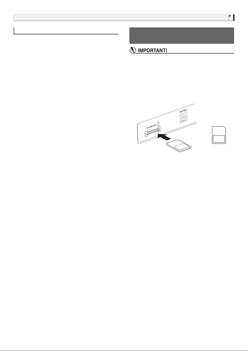
Using a Memory Card
E-87
• Be sure to observe the precautions provided in the
documentation that comes with the memory card.
• Memory cards have a write-protect switch. Use it when you
want to protect the data on the card from accidental
deletion.
• Avoid using a memory card under the following conditions.
Such conditions can corrupt data stored on the memory
card.
– Areas subjected to high temperature, high humidity, or
corrosive gas.
– Areas subjected to strong electrostatic charge and digital
noise.
• Never touch the contacts of a memory card when loading it
or removing it from the Synthesizer.
• The message “Please Wait” will remain on the display while
a data save operation is in progress. Do not perform any
other operation while it is displayed.
Turning off the Synthesizer or removing the memory card
can cause Synthesizer data to be deleted or become
corrupted. It also can cause the Synthesizer to fail to turn
on when
6
POWER is pressed. If this happens, refer to
“Troubleshooting” (page E-95).
• If the message “No Card” appears on the display, it means
there is no memory card in the card slot. For details about
what appears on the display while a card is loaded, see
“Playing a Music File from a Memory Card” (page E-91).
• Never insert anything besides a memory card into the card
slot. Doing so creates the risk of malfunction.
• Electrostatic charge from your fingers or the memory card
to the card slot can cause malfunction of the Synthesizer. If
this happens, turn the Synthesizer off and then back on
again.
• A memory card can become quite warm after very long use
in the card slot. This is normal and does not indicate
malfunction.
• A memory card must be positioned correctly when
being loaded into the Synthesizer. Trying to force an
improperly oriented memory card into the slot can
damage the memory card and the slot.
1.
With the top of the memory card facing
upwards (so you can see it), carefully insert it
into the Synthesizer’s SD card slot (
ck
) until
stops with a click.
2.
To remove the memory card first press it into
the slot further.
• This will cause the memory card to disengage and eject
partially. Pull the memory card the rest of the way out of
the slot.
Card and Card Slot Precautions
Loading and Removing a Memory
Card
Top
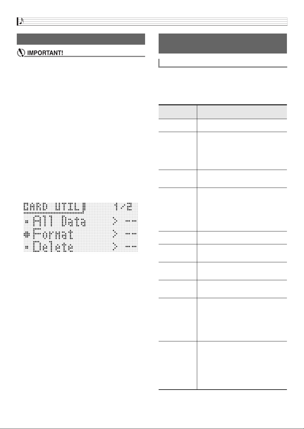
Using a Memory Card
E-88
• Format a memory card before using it for the first time.
• Before formatting a memory card, make sure it does
not have any valuable data stored on it.
• The memory card format operation performed by this
Synthesizer is a “quick format”. If you want to
completely delete all of the data on the memory card,
format it on your computer or some other device.
1.
Insert the memory card you want to format into
the Synthesizer’s card slot.
• Make sure the memory card is write-enabled. Check
the position of the card’s write-protect switch to ensure
it is not in the write-protect position.
2.
Press
7
SETTING.
3.
Use the
br
up (q) and down (w) buttons to
move the item selection cursor (0) to
“CardUtility” and then press
br
ENTER.
• This causes the “CARD UTIL” screen to appear.
4.
Use the
br
up (q) and down (w) buttons to
move the item selection cursor (0) to “Format”.
5.
Press the
br
ENTER button.
• This will cause the confirmation message “Sure?” to
appear.
6.
Press the
br
YES button to format the memory
card or the
br
NO button to cancel.
• The message “Please Wait” will remain on the display
while the format operation is being performed. Do not
perform any Synthesizer operation while this message
is on the display. “Complete!” appears on the display
after formatting is complete.
• Formatting may take as long as a few minutes to
complete.
1.
Insert the memory card into the card slot.
2.
Depending on the type of data you want to save
to the memory card, perform one of the steps
shown below.
Formatting a Memory Card Saving Synthesizer Data to a
Memory Card
To save Synthesizer data to a memory card
To save this
type of data:
Perform these steps:
One user
performance
1. Press
7
PERFORM.
2. Press
br
MENU.
One user tone
(User Solo
Synthesizer tone,
user PCM melody
tone, user PCM
drum tone, user
wave tone)
1. Press
7
TONE.
2. Use the
bp
dial or
bq
number buttons to
select a tone.
3. Press
br
MENU.
One user wave 1. Hold down
bm
REC until “LOOPER” appears
on the display.
2. Press
br
MENU.
One user DSP 1. Hold down
bn
MIXER until the EFFECT
screen appears on the display.
2. Use the
br
cursor (U, q, w, I) buttons
to move the item selection cursor (0) to
“DSP Select” and then press
br
ENTER.
• “Ent” is not displayed in the case of a Solo
Synthesizer tone.
3. Press
br
MENU.
One user step
sequence
1. Press
7
STEP SEQ.
2. Press
br
MENU.
One step
sequence chain
1. Hold down
bk
CHAIN until the CHAIN
screen appears on the display.
2. Press
br
MENU.
One user phrase 1. Hold down
bo
KEY PLAY until the PHRASE
screen appears on the display.
2. Press
br
MENU.
One user arpeggio 1. Hold down
bn
ARPEGGIO until the
ARPEGGIO screen appears on the display.
2. Press
br
MENU.
All data 1. Press
7
SETTING.
2. Use the
br
up (q) and down (w)
buttons to move the item selection cursor
(0) to “CardUtility” and then press
br
ENTER.
3. Use the
br
up (q) and down (w)
buttons to move the item selection cursor
(0) to “All data” and then press
br
ENTER.
Setting data 1. Press
7
SETTING.
2. Use the
br
up (q) and down (w)
buttons to move the item selection cursor
(0) to “CardUtility” and then press
br
ENTER.
3. Use the
br
up (q) and down (w)
buttons to move the item selection cursor
(0) to “SettingData” and then press
br
ENTER.
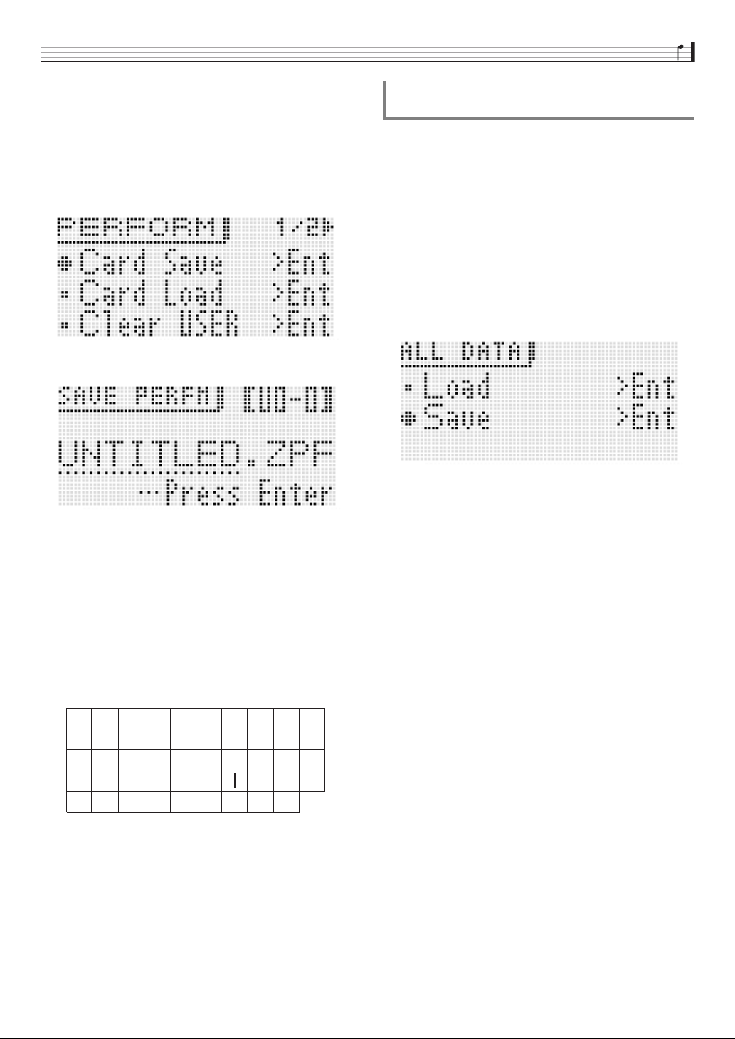
Using a Memory Card
E-89
3.
Use the
br
up (q) and down (w) buttons to
move the item selection cursor (0) to “Card
Save” (or “Save” if you want to save all data)
and then press
br
ENTER.
• This displays a screen like the one shown below. (As
an example, the remainder of this procedure uses the
screen that appears when you perform these steps
from the Performance Mode.)
4.
Press
br
ENTER.
5.
Enter a number (and, if required, the applicable
bank) and file name.
You can perform the following steps to change the initial
default file name that is assigned automatically.
• For details about inputting characters, see “Creating
Tones” on page E-12.
• The characters you can select are shown below.
• The three characters at the end of a file name are a file
name extension, which indicates the type of data stored
in the file.
6.
After everything is the way you want, press the
br
(ENTER) button.
7.
In response to the “Sure?” message that
appears, press the
br
YES button to save or
the
br
NO button to cancel.
1.
Press
7
SETTING.
2.
Use the
br
up (q) and down (w) buttons to
move the item selection cursor (0) to
“CardUtility” and then press
br
ENTER.
• This causes the “CARD UTIL” screen to appear.
3.
Use the
br
up (q) and down (w) buttons to
move the item selection cursor (0) to “ALL
Data” and then press
br
ENTER.
4.
Use the
br
up (q) and down (w) buttons to
move the item selection cursor (0) to “Save”.
• The remainder of the steps are the same as those from
step 3 under “To save Synthesizer data to a memory
card” (page E-88).
■ Memory card Data Storage
The above procedure stores Synthesizer data in a folder
named MUSICDAT on the memory card.
• The MUSICDAT folder is created automatically when you
format the memory card on the Synthesizer (page E-88).
• Note that files not in the MUSICDAT folder cannot be
loaded, deleted, or renamed by this Synthesizer. You also
will not be able to load or delete any file stored in any
subfolder inside the MUSICDAT folder.
(1) Use the
br
cursor (U, I) buttons to move the cursor
to the character you want to change.
(2) Use the
bp
dial or
br
minus (–) and plus (+)
buttons to change the character.
9
J
T
'
8
I
S
_
`
7
H
R
&
~
6
G
Q
S
@
5
F
P
Z
}
4
E
O
Y
{
3
D
N
X
^
2
C
M
W
-
1
B
L
V
)
0
A
K
U
(
To batch save all Synthesizer data to a
memory card
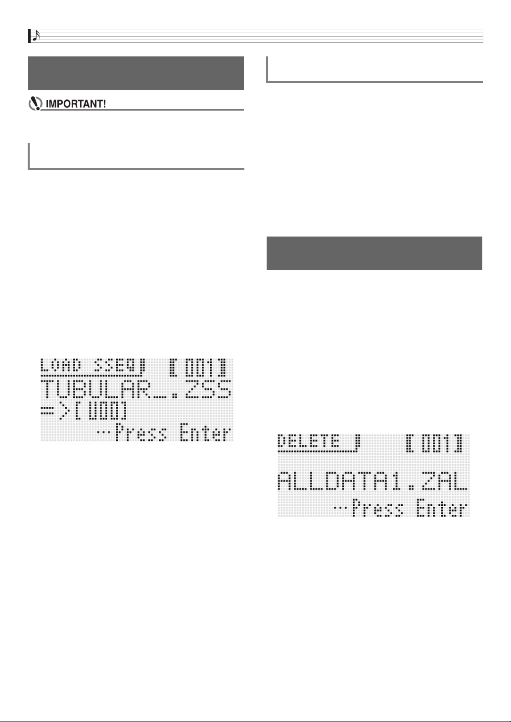
Using a Memory Card
E-90
• Make sure that all of the data you want to load is in the
MUSICDAT folder on the memory card.
1.
Insert the memory card into the card slot.
2.
Referring to the table in step 2 of the procedure
under “To save Synthesizer data to a memory
card” (page E-88), perform the procedure
required for the type of data you want to load
from the card.
3.
Use the
br
up (q) and down (w) buttons to
move the item selection cursor (0) to “Card
Load” (or “Load” if you want to load all data)
and then press
br
ENTER.
• This causes a menu screen like the one shown below
to appear on the display. The sample screen below
shows the screen that appears when you perform this
procedure from the Step Sequencer Mode.
4.
Use the
bp
dial or
br
minus (–) and plus (+)
buttons to display the file you want to import.
5.
Use the
br
down (w) button to move the
cursor downwards, and then use the
bp
dial or
br
minus (–) and plus (+) buttons to display the
destination of the load operation.
6.
Press the
br
ENTER button.
7.
In response to the “Sure?” message that
appears, press the
br
YES button to load or the
br
NO button to cancel.
1.
Press
7
SETTING.
2.
Use the
br
up (q) and down (w) buttons to
move the item selection cursor (0) to
“CardUtility” and then press
br
ENTER.
• This causes the “CARD UTIL” screen to appear.
3.
Use the
br
up (q) and down (w) buttons to
move the item selection cursor (0) to “All
Data” and then press
br
ENTER.
• The remainder of the steps are the same as those from
step 3 under “To load data to Synthesizer memory from
a memory card” (page E-90).
1.
Insert the memory card into the card slot.
2.
Press
7
SETTING.
3.
Use the
br
up (q) and down (w) buttons to
move the item selection cursor (0) to
“CardUtility” and then press
br
ENTER.
• This causes the CARD UTIL screen to appear.
4.
Use the
br
up (q) and down (w) buttons to
move the item selection cursor (0) to “Delete”
and then press the
br
ENTER button.
• This displays a screen for specifying the file to be
deleted.
5.
Use the
bp
dial or
br
minus (–) and plus (+)
buttons to display the file you want to delete.
6.
Press the
br
ENTER button.
7.
In response to the “Sure?” message that
appears, press the
br
YES button to delete or
the
br
NO button to cancel.
• Pressing the
br
YES button displays the message
“Please Wait” (indicating the operation is in progress).
Do not perform any operation while this message is on
the display. “Complete!” appears on the display after
the operation is complete.
Loading Data from a Memory
Card
To load data to Synthesizer memory from a
memory card
To batch load all Synthesizer memory data
from a memory card
To delete a file from a memory
card

Using a Memory Card
E-91
1.
Insert the memory card into the card slot.
2.
Press
7
SETTING.
3.
Use the
br
up (q) and down (w) buttons to
move the item selection cursor (0) to
“CardUtility” and then press
br
ENTER.
• This causes the CARD UTIL screen to appear.
4.
Use the
br
cursor (U, q, w, I) buttons to
move the item selection cursor (0) to
“Rename” and then press the
br
ENTER
button.
• This displays a screen for specifying the file to be
renamed.
5.
Use the
bp
dial or
br
minus (–) and plus (+)
buttons to display the file you want to rename.
6.
Use the
br
left (U) and right (I) buttons to
move the cursor to the name character position
you want to change, and then use the
bp
dial or
br
minus (–) and plus (+) buttons to select the
character you want.
7.
After the name is the way you want, press the
br
ENTER button.
8.
In response to the “Sure?” message that
appears, press the
br
YES button to rename
the file or the
br
NO button to cancel.
• Pressing the
br
YES button displays the message
“Please Wait” (indicating the operation is in progress).
Do not perform any operation while this message is on
the display. “Complete!” appears on the display after
the operation is complete.
You can use the Synthesizer to play music files that you have
saved to a card with your computer.
For details about the playback method, see “Playing a Demo
Tune or a File from a Memory Card” on page E-84.
To rename a file on a memory
card
Playing a Music File from a
Memory Card
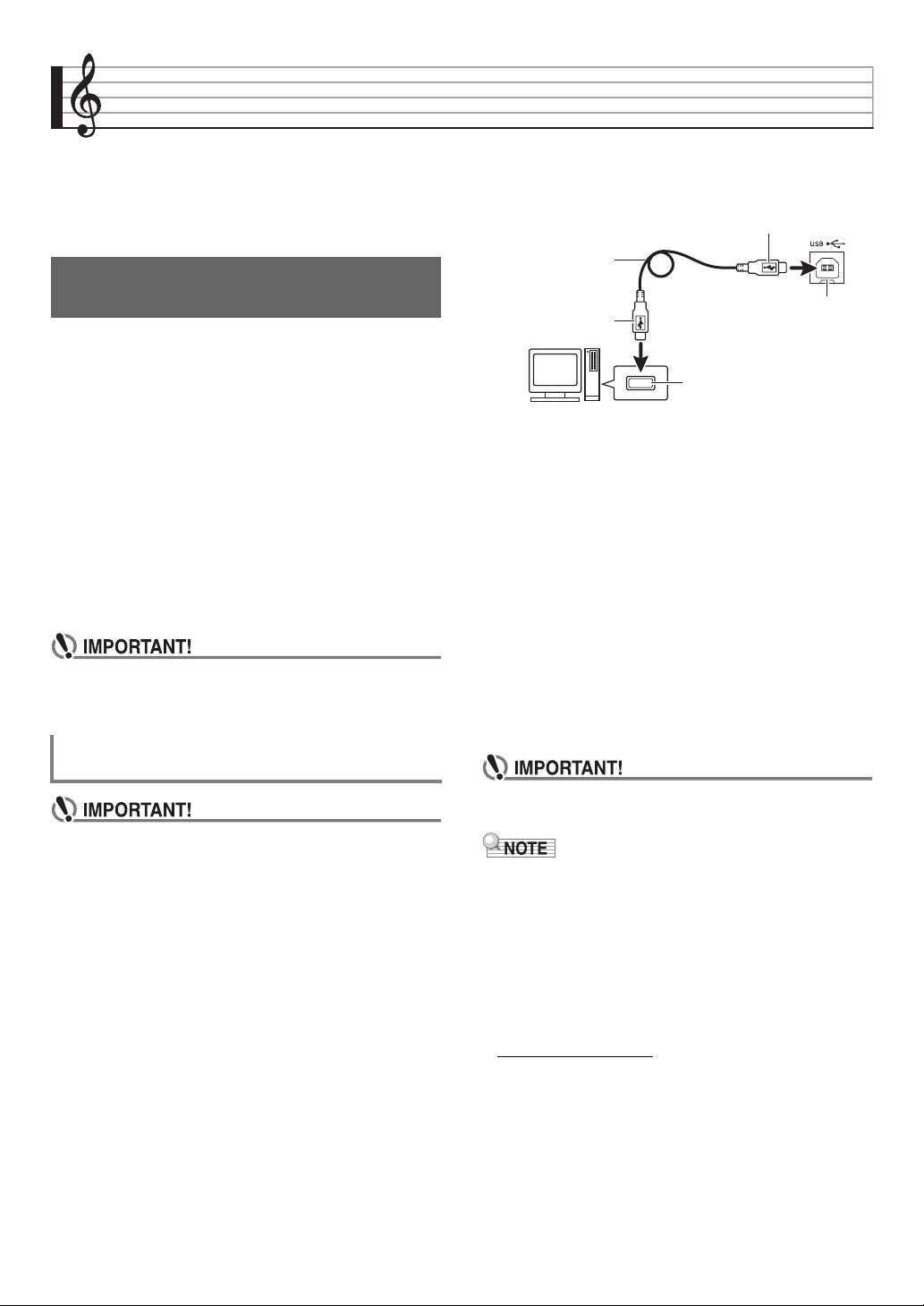
E-92
Connecting to a Computer
You can connect the Synthesizer to a computer and
exchange MIDI data between them. You can send play data
from the Synthesizer to commercially available music
software running on your computer, or you can send MIDI
data from your computer to the Synthesizer for playback.
The following shows the minimum computer system
requirements for sending and receiving MIDI data. Check to
make sure that your computer complies with these
requirements before connecting the Synthesizer to it.
• Operating System
•USB port
• Never connect to a computer that does not conform to
the above requirements. Doing so can cause problems
with your computer.
• Make sure you follow the steps of the procedure below
exactly. Connecting incorrectly can make data send
and receive impossible.
1.
Turn off the Synthesizer and then start up your
computer.
• Do not start up the music software on your computer
yet!
2.
After starting up your computer, use a
commercially available USB cable to connect it
to the Synthesizer.
3.
Turn on the Synthesizer.
• If this is the first time you are connecting the
Synthesizer to your computer, the driver software
required to send and receive data will be installed on
your computer automatically.
4.
Start up commercially available music software
on your computer.
5.
Configure the music software settings to select
one of the following as the MIDI device.
• For information about how to select the MIDI device,
see the user documentation that comes with the music
software you are using.
• Be sure to turn on the Synthesizer first before starting
up your computer’s music software.
• Once you are able to connect successfully for the first time,
there is no problem with leaving the USB cable connected
when you turn off your computer and/or Synthesizer.
• You can alter the Synthesizer’s MIDI setup by changing the
MIDI data send channel or other settings. For details, see
“MIDI Settings” (page E-82).
• For detailed specifications and connections that apply to
MIDI data send and receive by this Synthesizer, see the
latest support information provided by the website at the
following URL.
http://world.casio.com/
Minimum Computer System
Requirements
Windows
®
XP (SP2 or later)
*1
Windows Vista
®
*2
Windows
®
7
*3
Mac OS
®
X (10.3.9, 10.4.11, 10.5.X, 10.6.X, 10.7.X)
*1: Windows XP Home Edition
Windows XP Professional (32-bit)
*2: Windows Vista (32-bit)
*3: Windows 7 (32-bit, 64-bit)
Connecting the Synthesizer to Your
Computer
CASIO USB-MIDI : (For Windows 7, Windows Vista,
Mac OS X)
USB Audio Device : (For Windows XP)
Computer USB port
A connector
B connector
Synthesizer USB port
USB cable
(A-B type)

Connecting to a Computer
E-93
You can transfer user tones, phrases, and other data you
saved with the Synthesizer to a computer for storage. Later,
you can return the data back to the Synthesizer when you
need it.
You can also edit tone, performance and other Synthesizer
data on a computer, where it is easier to work with. A special
Data Editor application is required in order to perform
operations such as these.
1.
Go to the CASIO WORLDWIDE site at the
following URL.
http://world.casio.com/
2.
At the site, select a geographic area or country.
3.
After accessing the area site, navigate to the
minimum computer system requirements for
Data Editor for this product.
• You should be able to find a link to Data Editor
information on the product introduction page of this
product. If you cannot find such a link, use the search
form of the area site where you are located to enter the
model name of this product and search for it.
• Note that site contents are subject to change without
notice.
4.
Check if your computer system complies with
the minimum requirements for Data Editor.
5.
Download Data Editor and its user’s guide to
your computer.
6.
Follow the procedure in the Data Editor user’s
guide you downloaded in step 5 to install Data
Editor.
7.
Use the procedures in the Data Editor user’s
guide to transfer and edit data.
• See the Data Editor user’s Guide for information about
the types of data that can be transferred and the data
that can be edited.
Saving and Loading Synthesizer
Data to a Computer and Editing
Synthesizer Data on a Computer
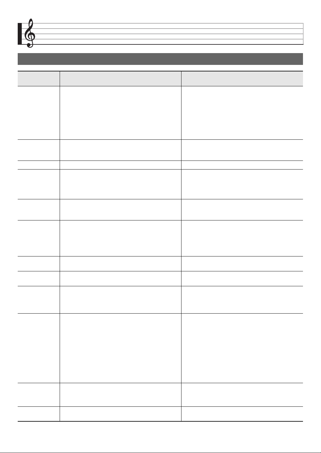
E-94
Reference
Error Messages
Display
Message
Cause Required Action
Format 1. The current memory card format is not compatible
with this Synthesizer.
1. Format the memory card on the Synthesizer (page
E-88).
2. The memory card capacity is greater than 32GB. 2. Use a memory card with a capacity of 32GB or
less.
3. You are trying to use an SDXC card. 3. SDXC cards not supported. Use an SD or SDHC
memory card.
4. There is something wrong with the memory card. 4. Use a different memory card.
Card Full There is not enough room available on the memory
card.
Delete some of the files on the memory card to make
room for new data (page E-90), or use a different
card.
Card R/W Memory card data is corrupted. Use a different memory card.
No Card 1. The memory card is not loaded correctly in the
Synthesizer’s card slot.
1. Correctly load the memory card into the card slot.
2. The memory card was removed while some
operation was in progress.
2. Do not remove the memory card while any
operation is in progress.
No Data You tried to save a Synthesizer user area (user
rhythm, user rhythm song, etc.) that does not contain
any data to the memory card.
Select a user area that contains data.
No File 1. There is no MUSICDAT folder (page E-89) on the
memory card.
1. Create a MUSICDAT folder on the memory card or
format the memory card on the Synthesizer (page
E-88).
2. There is no loadable or playable data in the
MUSICDAT folder.
2. Move the file you want to load or play into the
memory card’s MUSICDAT folder.
Not SMF0/1 You are attempting to play back SMF Format 2 file. This Synthesizer supports playback of SMF Format 0
or Format 1 only.
Protect The memory card is write-protected. Use the memory card’s write protect switch to enable
writing.
Read Only A read-only file with the same name you are trying to
use is already stored on the memory card.
• Use a different name to save the new file.
• Remove the read-only attribute from the existing
file and overwrite it with the new file.
• Use a different memory card.
Size Over 1. The data on the memory card is too big to play. 1. This Synthesizer supports playback of song data
files with a maximum size of about 320KB.
2. The data you are trying to load is too large. 2. The following is the approximate maximum data
sizes (per data item) when loading data into
Synthesizer memory.
User phrase: 8KB
A total of approximately 128KB of user phrase
(total of all 100 user presets) can be loaded.
3. Chain SMF data size is too large to convert the
data and save it to a card.
3. The Synthesizer can convert up to 320KB of chain
SMF data and save it to a card.
Wrong Data 1. The memory card data is corrupted. Use a different memory card.
2. The memory card contains data that is not
supported by this Synthesizer.
Memory Full There is not enough memory capacity required for
phrase sequencer operations.
Shorten the phrase so it takes up less memory space.
Reference
E-95
File Name When renaming a file on a memory card, attempting
to specify a file name that is already used.
Use a different name.
Invalid Tone You selected a Synthesizer tone for a part other than
PART1 (ZONE1).
Select Synthesizer only for PART1 (ZONE1).
Battery Low Battery power is low. Replace the batteries or change to AC adaptor power
(page E-9).
Write Error! Writing to internal storage memory failed. Try again.
Troubleshooting
Symptom Action
Included Accessories
I can’t find something that should be
included with the product.
Carefully check inside all of the packing materials.
Power Requirements
Power will not turn on. • Check the AC adaptor or make sure that the batteries are facing correctly (page
E-9).
• Replace the batteries with new ones or switch over to AC adaptor power (page
E-9).
The display lights up momentarily but
power does not turn on when I press
6
POWER.
Press
6
POWER firmly and completely to turn on power.
The Synthesizer outputs a loud sound and
then suddenly powers down.
Replace the batteries with new ones or switch over to AC adaptor power (page
E-9).
The Synthesizer suddenly powers down
after a few minutes.
This happens when Auto Power Off (page E-10) is triggered.
Display
The display keeps going out or is flashing. Replace the batteries with new ones or switch over to AC adaptor power (page
E-9).
Screen contents are visible only from
straight ahead.
This is due to production limitations. It does not indicate malfunction.
Sound
Nothing happens when I press any
keyboard key.
• Adjust the main volume setting (page E-12).
• This Synthesizer does not have built-in speakers. It will no produce unless you
connect some device for sound output (page E-8).
No sound is produced when a start the
Step Sequencer.
When the arpeggio function is being triggered by start of the Step Sequencer, the
sequence will not start until you play something on the keyboard.
Notes keep sounding, without stopping. Replace the batteries with new ones or switch over to AC adaptor power (page
E-9).
Some notes are cut off while they are
playing.
Notes are cut off whenever the number of notes being sounded exceeds the
maximum polyphony value of 64 (1 to 32 for some tones). This does not indicate
malfunction.
The volume or tone setting I configured
has changed.
• Adjust the main volume setting (page E-12).
• Replace the batteries with new ones or switch over to AC adaptor power (page
E-9).
Output volume does not change even
though I change my keyboard pressure.
Change the Touch setting (page E-74).
Display
Message
Cause Required Action
Reference
E-96
In certain keyboard ranges, the volume
and tone quality sound are slightly
different from those in other keyboard
ranges.
This is due to system limitations. It does not indicate malfunction.
With some tones, octaves do not change
at the far ends of the keyboard.
This is due to system limitations. It does not indicate malfunction.
The pitch of the notes does not match
other accompanying instruments or
sounds strange when played along with
other instruments.
Check the transpose and octave shift settings (page E-36).
There is digital noise mixed with the sound
when I play high notes with a Solo
Synthesizer tone.
This is due to system limitations. It does not indicate malfunction.
The reverb of notes seems to change
suddenly.
Check and adjust the reverb setting (page E-36).
Computer Connection
I can’t exchange data between the
Synthesizer and a computer.
• Check to make sure that the USB cable is connected to the Synthesizer and
computer, and that the device is selected correctly with your computer’s music
software settings (page E-92).
• Turn off the Synthesizer and then exit the music software on your computer.
Next, turn the Synthesizer back on and then restart the music software on your
computer.
Symptom Action
Reference
E-97
Specifications
Model XW-G1
Keyboard 61 standard-size keys
Touch Response 2 types, Off
Maximum Polyphony 64 notes (1 to 32 for some tones)
Tones 420 preset, 220 user
Solo Synthesizer Tones 100 preset, 100 user
PCM Melody Tones 300 preset, 100 user
PCM Drum Tones 20 preset, 10 user
User Wave Tones 10 user
Effects
Reverb System reverb
Chorus System chorus
DSP 100 preset, 100 user
53 types (46 normal, 7 Solo Synthesizer)
Master Equalizer 4 bands
Demo Songs 3 songs
Performance Functions 100 preset, 100 user
Phrase Functions
Preset Phrases 100
User Phrases 100
Playback Mode One time, loop
Memory Capacity 128KB
Other Overdubbing
Step Sequencer Functions
Preset Sequences 100
User Sequences 100
Number of Tracks Mono: 8, Poly: 1, Control: 4
Patterns 8 types per sequence
Chains 100
Maximum Steps 16
Other Phrase function control
Sample Looper Function
User samples 10
Sampling frequencies 42 kHz, 21 kHz
Sampling channels Stereo, monaural
Quantization 16bit
Mixer 16 internal parts + Externally input parts
Other Functions
Transpose ±1 octaves (–12 to 0 to +12 semitones)
Octave Shift ±3 octaves
Tuning A4 = 415.5 - 440.0 - 465.9 Hz
Arpeggios Preset: 100
User: 100
MIDI 16 multi-timbre received, GM Level 1 standard
Wheels Bender, modulation
Memory Cards
Supported Memory Cards SD or SDHC memory cards, 32GB or less
Functions SMF playback, file storage, file recall, file delete, card format
Reference
E-98
• Design and specifications are subject to change without notice.
Inputs/Outputs
USB port TYPE B
MIDI IN/OUT terminal IN, OUT
Sustain/Assignable jack Standard jack (sustain, sostenuto, soft, start/stop)
Phones jack Stereo standard jack
Line Out R, L/MONO jacks Standard jack × 2
Output Impedance: 2.3kΩ, Output Voltage: 1.7V (RMS) MAX
Audio In jack Stereo mini jack
Input Impedance: 9kΩ, Input Sensitivity: 200mV
Inst In jack Standard jack
Input Impedance: 9kΩ, Input Sensitivity: 200mV
Mic In jack Standard jack (connect a dynamic microphone only)
Input Impedance: 3kΩ, Input Sensitivity: 10mV
Inst In, Mic In A/D conversion: 42 kHz, 10bit
Power Jack 9.5V DC
Power Supply 2-way
Batteries 6 D-size zinc-carbon batteries or alkaline batteries
Battery Life Approximately 35 hours (alkaline batteries, using the optional CASIO CP-16 headphones)
AC Adaptor AD-E95100L
Auto Power Off Approximately 6 minutes after last key operation during battery use,
approximately 4 hours after last key operation during AC adaptor use. Auto Power Off can be
disabled.
Power Consumption 9.5V = 4W
Dimensions 94.8 × 38.4 × 12.4 cm (37
3
/8 × 15
1
/8 × 4
7
/8 inch)
Weight Approximately 5.4kg (11.9 lbs) (without batteries)
Be sure to read and observe the following operating
precautions.
■ Location
Avoid the following locations for this product.
• Areas exposed to direct sunlight and high humidity
• Areas subjected to temperature extremes
• Near a radio, TV, video deck, or tuner
The above devices will not cause malfunction of the
product, but the product can cause interference in the audio
or video of a nearby device.
■ User Maintenance
• Never use benzine, alcohol, thinner, or other chemical
agents to clean the product.
• To clean the product or its keyboard, wipe with a soft cloth
moistened in a weak solution of water and a mild neutral
detergent. Wring all excess moisture from the cloth before
wiping.
■ Included and Optional Accessories
Use only accessories that are specified for use with this
product. Use of unauthorized accessories creates the risk of
fire, electric shock, and personal injury.
■ AC Adaptor Handling Precautions
• Use a power outlet that is easily accessible so you can
unplug the AC adaptor when a malfunction occurs or
whenever else you need to do so.
• The AC adaptor is intended for indoor use only. Do not use
it where it might be exposed to splashing or moisture. Do
not place any container, such as a flower vase, that
contains liquid on the AC adaptor.
• Store the AC adaptor in a dry place.
• Use the AC adaptor in an open, well-ventilated area.
• Never cover the AC adaptor with newspaper, a table cloth,
a curtain, or any other similar item.
• Unplug the AC adaptor from the power outlet if you do not
plan to use the product for a long time.
• Never try to repair the AC adaptor or modify it in any way.
• AC adaptor operating environment
Temperature: 0 to 40°C
Humidity: 10% to 90% RH
• Output polarity: &
■ Weld Lines
Lines may be visible on the exterior of the product. These are
“weld lines” that result from the plastic molding process. They
are not cracks or scratches.
■ Musical Instrument Etiquette
Always be aware of others around you whenever using this
product. Be especially careful when playing late at night to
keep the volume at levels that do not disturb others. Other
steps you can take when playing late at night are closing
windows and using headphones.
Operating Precautions
Reference
E-99
■ Normal DSP Types
• Type numbers 01 through 14 are single type DSPs, while numbers 15 through 46 are dual type DSPs. A single type DSP is one
with a single structure, while a dual type is a combination of two single type DSPs.
• The name of a dual DSP is formed by its two constituent single DSP names, in the order that they are applied. For example, type
15 named “Wah-Compressor” connects in line to “Wah” and “Compressor”, in that sequence.
• For details about parameters that can be configured with each DSP type, refer to the sections shown in the table below.
■ Solo Synthesizer DSP Types
• For information about the parameters whose settings can be configured for each DSP type, see “Solo Synthesizer DSP
Parameters” (page E-102).
DSP Effect List
DSP Type List
For information about this DSP type: Go here:
Single type (Type numbers 01 through 14) Normal DSP Single Type DSP Parameters (page E-100)
Dual type (Type numbers 15 through 46) Normal DSP Dual Type DSP Parameters (page E-102)
Type Number DSP Type Name Screen Name
01 Wah Wah
02 Compressor Comp
03 Distortion Dist
04 Enhancer Enhance
05 AutoPan AutoPan
06 Tremolo Tremolo
07 Phaser Phaser
08 Flanger Flanger
09 Chorus Chorus
10 Delay Delay
11 Reflection Reflect
12 Rotary Rotary
13 RingModulator RingMod
14 Lo-Fi Lo-Fi
15 Wah-Compressor WahCmp
16 Wah-Distortion WahDst
17 Wah-Chorus WahCho
18 Wah-Flanger WahFln
19 Wah-Reflection WahRef
20 Wah-Tremolo WahTrm
21 Wah-AutoPan WahPan
22 Compressor-Wah CmpWah
23 Compressor-Distortion CmpDst
24 Compressor-Chorus CmpCho
25 Compressor-Flanger CmpFln
26 Compressor-Reflection CmpRef
27 Compressor-Tremolo CmpTrm
28 Compressor-AutoPan CmpPan
29 Distortion-Wah DstWah
30 Distortion-Compressor DstCmp
31 Distortion-Chorus DstCho
32 Distortion-Flanger DstFln
33 Distortion-Reflection DstRef
34 Distortion-Tremolo DstTrm
35 Distortion-AutoPan DstPan
36 Chorus-Reflection ChoRef
37 Chorus-AutoPan ChoPan
38 Flanger-Reflection FlnRef
39 Flanger-AutoPan FlnPan
40 Reflection-Distortion RefDst
41 Reflection-Chorus RefCho
42 Reflection-AutoPan RefPan
43 Tremolo-Distortion TrmDst
44 Tremolo-Chorus TrmCho
45 Tremolo-Flanger TrmFln
46 Tremolo-Reflection TrmRef
Type Number DSP Type Name Screen Name
Type Number DSP Type Name Screen Name
Bypass Bypass
01 Auto Pan AutoPan
02 Distortion Dist
03 Flanger Flanger
04 Chorus Chorus
05 Delay Delay
06 Ring Modulator RingMod
Type Number DSP Type Name Screen Name

Reference
E-100
■ Normal DSP Single Type DSP Parameters
01: Wah
This is a “wah” effect that can automatically affect the
frequency using an LFO.
Parameters and Value Ranges:
1 :Resonance (0 to 127)
Adjusts the strength of resonance.
2 :Manual (0 to 127)
Adjusts the wah filter reference frequency.
3 :LFO Rate (0 to 127)
Adjusts the LFO rate.
4 :LFO Depth (0 to 127)
Adjusts the LFO depth.
5 :LFO Waveform (off, sin, tri, random)
Selects the LFO waveform.
02: Compressor
Compresses the input signal, which can have the effect of
suppressing level variation and make it possible to sustain
dampened sounds longer.
Parameters and Value Ranges:
1 :Attack (0 to 127)
Adjusts the attack amount of the input signal. A smaller
value causes prompt compressor operation, which
suppresses the attack of the input signal. A larger values
delays compressor operation, which causes the attack of
the input signal to be output as-is.
2 :Release (0 to 127)
Adjusts the time from the point the input signal drops
below a certain level until the compression operation is
stopped. When an attack feeling is desired (no
compression at the onset of sound), set this parameter to
as low a value as possible. To have compression applied
at all times, set a high value.
3 :Level (0 to 127)
Adjusts the output level.
4 :Threshold (0 to 127)
Adjusts the volume level at which the compression
operation starts.
03: Distortion
Digital distortion that applies an overtone to the input signal
and distorts it.
Parameters and Value Ranges:
1 :Gain (0 to 127)
Adjusts the input signal gain.
2 :Level (0 to 127)
Adjusts the output level.
04: Enhancer
Phase shifts low-range sounds and high-range sounds of the
input signal to enhance the signal’s profile.
Parameters and Value Ranges:
1 :Low Frequency (0 to 127)
Adjusts the low range enhancer frequency.
2 :Low Phase (0 to 127)
Adjusts the phase shift amount of the low-range enhancer.
3 :High Frequency (0 to 127)
Adjusts the high range enhancer frequency.
4 :High Phase (0 to 127)
Adjusts the phase shift amount of the high-range
enhancer.
05: Auto Pan
Performs continual left-right panning of the input signal using
an LFO.
Parameters and Value Ranges:
1 :LFO Rate (0 to 127)
Adjusts the panning rate.
2 :LFO Depth (0 to 127)
Adjusts the panning depth.
3 :LFO Waveform (sin, tri)
Selects the LFO waveform.
4 :Manual (Range: –64 to 0 to 63)
Adjusts the pan (stereo position).
–64 is full left, 0 is center, and 63 is full right.
06: Tremolo
Adjusts the volume of the input signal using an LFO.
Parameters and Value Ranges:
1 :LFO Rate (0 to 127)
Adjusts the tremolo rate.
2 :LFO Depth (0 to 127)
Adjusts the tremolo depth.
3 :LFO Waveform (sin, tri)
Selects the LFO waveform.
07: Phaser
Produces a distinctive pulsating, broad sound by using an
LFO to change the phase of the input signal and then mixes it
with the original input signal.
Parameters and Value Ranges:
1 :Resonance (0 to 127)
Adjusts the strength of the resonance.
2 :LFO Rate (0 to 127)
Adjusts the LFO rate.
3 :LFO Depth (0 to 127)
Adjusts the LFO depth.
4 :LFO Waveform (sin, tri, random)
Selects the LFO waveform.
DSP Parameter List

Reference
E-101
08: Flanger
Applies wildly pulsating and metallic reverberation to sounds.
LFO waveform is selectable.
Parameters and Value Ranges:
1 :LFO Rate (0 to 127)
Adjusts the LFO rate.
2 :LFO Depth (0 to 127)
Adjusts the LFO depth.
3 :LFO Waveform (sin, tri, random)
Selects the LFO waveform.
4 :Feedback (0 to 127)
Adjusts the strength of feedback.
09: Chorus
Gives sounds depth and breadth. Chorus type is selectable.
Parameters and Value Ranges:
1 :LFO Rate (0 to 127)
Adjusts the LFO rate.
2 :LFO Depth (0 to 127)
Adjusts the LFO depth.
3 :LFO Waveform (sin, tri)
Selects the LFO waveform.
4 :Feedback (0 to 127)
Adjusts the strength of feedback
5 :Type (mono, stereo, tri)
Selects the chorus type.
10: Delay
Delays the input signal and feeds it back to create a repeating
effect and give sounds more breadth.
Parameters and Value Ranges:
1 :Delay Time (0 to 127)
Adjusts the delay time.
2 :Feedback (0 to 127)
Adjusts the repeat of the delay.
3 :Ratio Lch (0 to 127)
Adjusts the delay time of the left channel. This value is a
ratio of the value specified for Delay Time.
4 :Ratio Rch (0 to 127)
Adjusts the delay time of the right channel. This value is a
ratio of the value specified for Delay Time.
5 :Wet Level (0, 1, 2, 3, 4, 5)
Adjusts the level of the delay sound.
6 :Type (1, 2)
Selects the delay type.
7 :Tempo Sync (Range: Off, 1/4, 1/3, 3/8, 1/2, 2/3, 3/4, 1,
4/3, 3/2, 2)
Adjusts the relationship between tempo and delay time of
the Sequencer.
When Off is selected, the current setting of the Delay Time
parameter is used for the delay time. When any other
setting is selected, the delay time is synced with the
Sequencer beat.
Selecting 1, for example, the delay time is approximately
equal to the length of one beat.
(Delay time is not precisely synced with the beat.)
Important!
When adjusting the delay time and type, certain settings can
result in a switching sound in the delay.
11: Reflection
An effector that extracts early reflections from reverb. Applies
acoustic presence to sounds.
Parameters and Value Ranges:
1 :Type (1, 2, 3, 4, 5, 6, 7, 8)
Selects from among the eight available reflection patterns.
2 :Feedback (0 to 127)
Adjusts the repeat of the reflected sound.
12: Rotary
This is a rotary speaker simulator.
Parameters and Value Ranges:
1 :Overdrive Gain (0, 1, 2, 3)
Adjusts overdrive gain.
2 :Overdrive Level (0 to 127)
Adjusts the overdrive output level.
3 :Speed (Slow, Fast)
Switches the speed mode between fast and slow.
4 :Brake (Rotate, Stop)
Stops speaker rotation.
5 :Fall Acceleration (0 to 127)
Adjusts acceleration when the speed mode is switched
from fast to slow.
6 :Rise Acceleration (0 to 127)
Adjusts acceleration when the speed mode is switched
from slow to fast.
7 :Slow Rate (0 to 127)
Adjusts the speaker rotation speed in the slow speed
mode.
8 :Fast Rate (0 to 127)
Adjusts the speaker rotation speed in the fast speed
mode.
13: Ring Modulator
Multiplies the input signal with an internal oscillator signal to
create a metallic sound.
Parameters and Value Ranges:
1 :OSC Frequency (0 to 127)
Sets the reference frequency of the internal oscillator.
2 :LFO Rate (0 to 127)
Adjusts the LFO rate.
3 :LFO Depth (0 to 127)
Adjusts the LFO depth.
4 :Type (1, 2, 3)
1 :Delay repeat determined by Delay Time.
2 :Delay repeat determined by Delay Time and Ratio L/R.
1 :Outputs the ring modulated signal only.
2 :Outputs the ring modulated signal and the input signal.
3 :Outputs a signal with a chorus effect applied to 2 (ring
modulated signal and input signal).
Reference
E-102
14: Lo-Fi
Applies various types of noise to the input signal to reproduce
a retro Lo-Fi sound.
Includes wow and flutter for rotational fluctuation like that in
tapes and records, a Noise 1 generator that generates
continual FM radio type, and a Noise 2 generator that
generates record play types scratch noise.
Parameters and Value Ranges:
1 :Wow and Flutter Rate (0 to 127)
Adjusts the wow and flutter rate.
2 :Wow and Flutter Depth (0 to 127)
Adjusts the wow and flutter depth.
3 :Noise1 Level (0, 1, 2, 3, 4, 5)
Adjusts the level of Noise Generator 1.
4 :Noise2 Level (0, 1, 2, 3, 4, 5)
Adjusts the level of Noise Generator 2.
5 :Noise2 Density (0, 1, 2, 3, 4, 5)
Adjusts the frequency of Noise Generator 2.
6 :Bit (0, 1, 2, 3)
Distorts the sound. A larger number produces greater
distortion.
Important!
Raising the noise level while a note is not sounding will cause
noise to sound, even if there is no input signal.
■ Normal DSP Dual Type DSP Parameters
Dual type DSPs are configured by combining two different
single type DSPs. Use the procedure below to determine what
parameters that can be configured for each dual type DSP,
and the operation, and setting ranges of dual type DSPs.
Example: Type number 29: Distortion-Wah
1. The DSP type name has two parts: a left side part and a
right side part.
Distortion-Wah 3 “Distortion” and “Wah”
2. Find out what parameters you can configure by looking up
the left side part of a dual type DSP in the “Type Name”
column of the table below.
3. Find the same type names in the table under “Normal DSP
Single Type DSP Parameters” on pages E-100 through
E-102, and note the operation and setting ranges of the
items that are the same as those shown in the
“Configurable Parameters” column of the above table.
4. Next, repeat steps 2 and 3 above for the right side part of
the dual type DSP parameter name.
■ Solo Synthesizer DSP Parameters
• (Param A) and (Param B) are parameters assigned to the
5
8/16 and MASTER sliders when Solo Synthesizer
tones are selected.
(No number): Bypass
Selecting this option disables application of DSP.
No parameters
01: Auto Pan
Parameters and Ranges
1 :LFO Waveform (Range: sin, tri)
2 :LFO Rate (Range: 0 to 127) (Param A)
3 :LFO Depth (Range: 0 to 127) (Param B)
4 :Manual (Range: –64 to 0 to 63)
02: Distortion
Parameters and Ranges:
1 :Gain (Range: 0 to 127) (Param A)
2 :Level (Range: 0 to 127) (Param B)
03: Flanger
Parameters and Ranges
1 :LFO Waveform (Range: sin, tri, random)
2 :LFO Rate (Range: 0 to 127) (Param A)
3 :LFO Depth (Range: 0 to 127) (Param B)
04: Chorus
Parameters and Ranges
1 :LFO Waveform (Range: sin, tri)
2 :LFO Rate (Range: 0 to 127) (Param A)
3 :LFO Depth (Range: 0 to 127) (Param B)
Type Name Configurable Parameters
Wah LFO Waveform
LFO Rate
LFO Depth
Distortion Gain
Level
Chorus LFO Waveform
LFO Rate
LFO Depth
Flanger LFO Waveform
LFO Rate
LFO Depth
Reflection Feedback
Compressor Threshold
Level
Auto Pan LFO Waveform
LFO Rate
LFO Depth
Manual
Tremolo LFO Waveform
LFO Rate
LFO Depth
• In our “Distortion-Wah” example, the left side part of the
name is “Distortion” so we can see in the above table
that “Gain” and “Level” parameters can be configured.
You can find out about the operations and setting ranges
of “Gain” and “Level” by referring to “03: Distortion” on
page E-100.
• The parameter numbers that appear on the parameter
setting screen start from 1, and the number is
incremented for each successive parameter.
The parameter numbers of our “Distortion-Wah” example
would be as shown below.
1: Gain
2: Level
3: LFO Waveform
4: LFO Rate
5: LFO Depth
Reference
E-103
05: Delay
Parameters and Ranges
1 :Delay Time (Range: 0 to 127) (Param A)
2 :Feedback (Range: 0 to 127)
3 :Damp (Range: 0 to 3)
Adjusts damping of the high-range. 3 results in maximum
damping.
4 :Wet Level (Range: 0, 1, 2, 3, 4, 5) (Param B)
5 :Tempo Sync (Range: Off, 1/4, 1/3, 3/8, 1/2, 2/3, 3/4, 1,
4/3, 3/2, 2)
06: Ring Modulator
Parameters and Ranges
1 :Frequency (Range: 0 to 127) (Param A)
Adjusts the modulation frequency of the ring modulator.
2 :Dry Level (Range: 0 to 127)
Adjusts the level of the original sound.
3 :Wet Level (Range: 0 to 127) (Param B)
Adjusts the sound level of the ring modulator.
• For information about parameters not included in the
above, see the explanations of the parameters with the
same names under “Normal DSP Single Type DSP
Parameters” (page E-100).
Supported Input Characters
Function Transmitted Recognized Remarks
Basic
Channel
1 - 16
1 - 16
1 - 16
1 - 16
Default
Changed
Note
Number
0 - 127
0 - 127
*
1True voice
After
Touch
Control
Change
X
X
X
O
Pitch Bender
OO
Key’s
Ch’s
Velocity
O
9nH v = 1 - 127
X
9nH v = 0, 8nH v =
**
O
9nH v = 1 - 127
X
9nH v = 0
Note ON
Note OFF
Mode
Mode 3
X
0 - 127
Mode 3
X
Default
Messages
Altered
Model: XW-G1 Version : 1.0
0
1
5
6, 38
7
10
11
16 - 19
64
65
Bank select
Modulation
Portamento Time
Data entry LSB, MSB
Volume
Pan
Expression
Hold 1
Portamento On/Off
O
O
O
O
O
O
X
O
O
O
*
2
*
2
*
2
*
3
*
2
O
O
O
O
O
O
O
O
O
O
*
2
*
2
*
2
*
2
**: no relation
MIDI Implementation Chart
Program
Change
OO
0 - 127:True #
System Exclusive
O
*
2
O
System
Common
X
X
X
X
X
X
: Song Pos
: Song Sel
: Tune
Aux
Messages
Remarks
X
O
X
O
X
X
O
O
O
O
O
X
: All sound off
: Reset all controller
: Local ON/OFF
: All notes OFF
: Active Sense
: Reset
System
Real Time
O
O
X
X
: Clock
: Commands
Mode 1 : OMNI ON, POLY
Mode 3 : OMNI OFF, POLY
Mode 2 : OMNI ON, MONO
Mode 4 : OMNI OFF, MONO
O : Yes
X : No
*
2
66
67
70 - 90
91
93
98, 99
100, 101
Sostenuto
Soft pedal
Reverb send
Chorus send
NRPN LSB, MSB
RPN LSB, MSB
O
O
O
O
O
O
O
*
3
*
3
*
2
*
2
*
2
O
O
O
O
O
O
O
*
2
*
2
*
2
*1: Depends on tone.
*
2: See MIDI Implementation at http://world.casio.com/.
*
3: In accordance with pedal effect setting.

MA1204-B Printed in China
XWG1-E-1B
K
This recycle mark indicates that the packaging conforms to
the environmental protection legislation in Germany.