Loading ...
Loading ...
Loading ...
2. Create a service loop with the copper tubing. Avoid kinks
when coiling the copper tubing. Secure copper tubing to
refrigerator cabinet with a "P" clamp.
A
_C
9
.........D
c
D
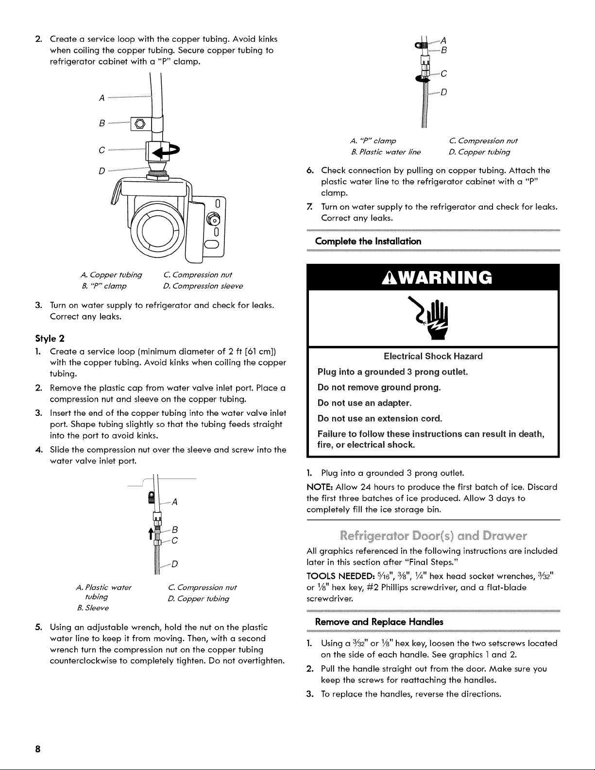
A. "P" clamp
B. Plastic water line
C. Compression nut
D. Copper tubing
6. Check connection by pulling on copper tubing. Attach the
plastic water line to the refrigerator cabinet with a "P"
clamp.
7. Turn on water supply to the refrigerator and check for leaks.
Correct any leaks.
Complete the Installation
A. Copper tubing
B. "P" clamp
C. Compression nut
D. Compression s/eeve
3. Turn on water supply to refrigerator and check for leaks.
Correct any leaks.
Style 2
1. Create a service loop (minimum diameter of 2 ft [61 cm])
with the copper tubing. Avoid kinks when coiling the copper
tubing.
2. Remove the plastic cap from water valve inlet port. Place a
compression nut and sleeve on the copper tubing.
3. Insert the end of the copper tubing into the water valve inlet
port. Shape tubing slightly so that the tubing feeds straight
into the port to avoid kinks.
4. Slide the compression nut over the sleeve and screw into the
water valve inlet port.
.
t ...... A
_JC
A. Plastic water C. Compression nut
tubing D. Copper tubing
B. Sleeve
Using an adjustable wrench, hold the nut on the plastic
water line to keep it from moving. Then, with a second
wrench turn the compression nut on the copper tubing
counterclockwise to completely tighten. Do not overtighten.
Electrical Shock Hazard
Plug into a grounded 3 prong outlet.
Do not remove ground prong.
Do not use an adapter.
Do not use an extension cord.
Failure to follow these instructions can result in death,
fire, or electrical shock.
1. Plug into a grounded 3 prong outlet.
NOTE. Allow 24 hours to produce the first batch of ice. Discard
the first three batches of ice produced. Allow 3 days to
completely fill the ice storage bin.
All graphics referenced in the following instructions are included
later in this section after "Final Steps."
TOOLS NEEDED: _6", %", 1/4" hex head socket wrenches, 3/32"
or 1/8" hex key, #2 Phillips screwdriver, and a flat-blade
screwdriver.
Remove and Replace Handles
1. Using a3//32"or 1/8" hex key, loosen the two setscrews located
on the side of each handle. See graphics 1 and 2.
2. Pull the handle straight out from the door. Make sure you
keep the screws for reattaching the handles.
3. To replace the handles, reverse the directions.
Loading ...
Loading ...
Loading ...