Loading ...
Loading ...
Loading ...
Apollo x8 Hardware Manual Front Panel 19
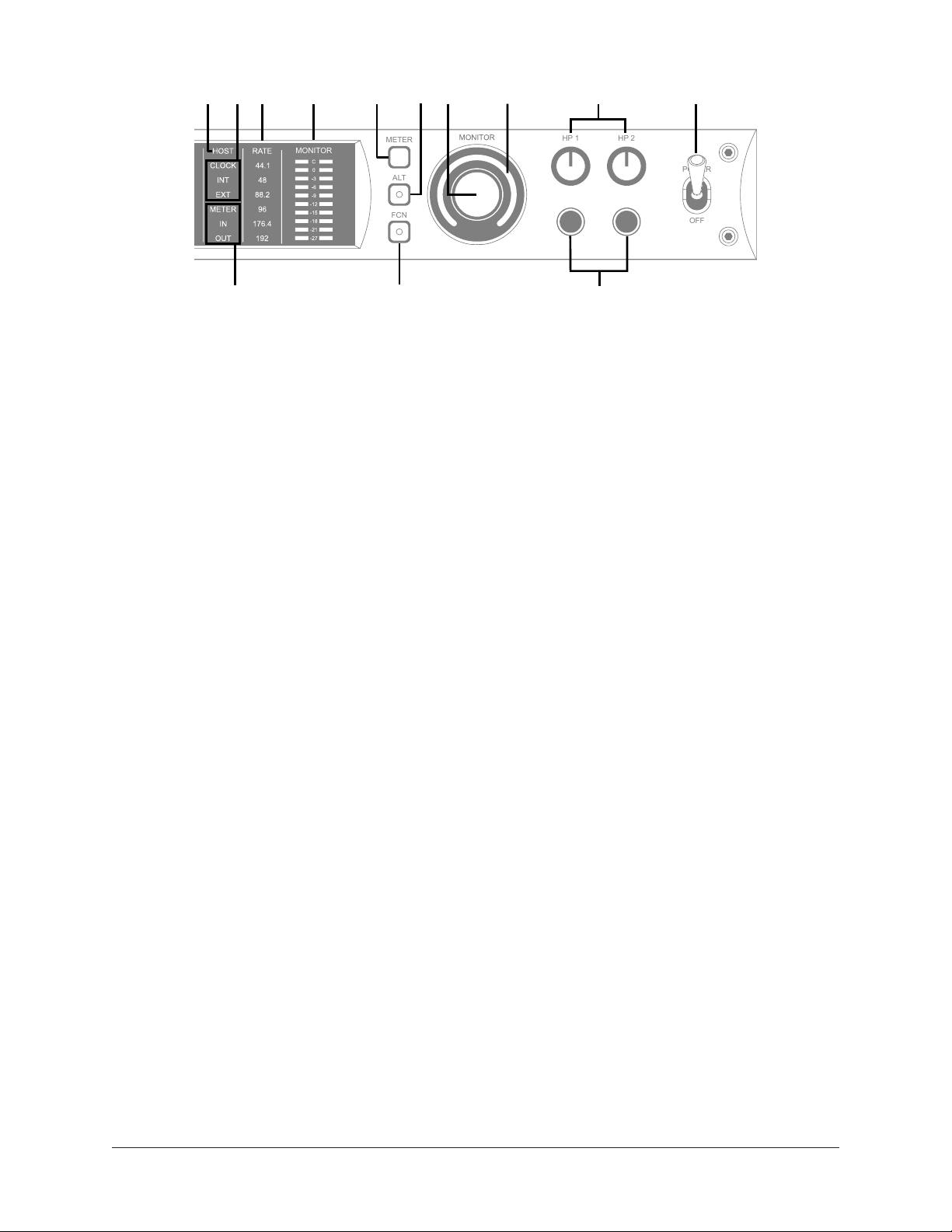
Apollo x8 front panel (right portion)
(15) HOST Indicator
The HOST indicator displays the status of the Thunderbolt connection to the host
computer system. The possible states are:
Lit – The unit is communicating with the host computer and operating normally.
Unlit – The unit is starting up or it is not recognized by the host computer. Verify
software installation and Thunderbolt connections.
Red – System error. Please contact UA technical support if the issue persists.
(16) CLOCK Indicators
The clock source and status are displayed with these indicators. Either internal (INT) or
external (EXT) is displayed. The clock source is set within the Console application; see
the Apollo Software Manual for details.
Internal Clock
When set to internal clock, the INT indicator is illuminated white.
External Clock
Apollo x8 can use an external digital clock source from the Word Clock, S/PDIF, or ADAT
inputs. The EXT indicator has two possible states:
White – When set to external clock and a valid clock signal is detected at the
specified port, the EXT indicator is illuminated white and Apollo x8 is synchronized to
the external clock source.
Red – When set to external clock and a valid clock signal is NOT detected at the
specified port, the EXT indicator is illuminated red and the internal clock remains
active instead. In this situation, if/when the specified external clock becomes
available, Apollo x8 switches back to the external clock, and the EXT indicator is
illuminated and white.
Important: When set to use any external clock source, Apollo x8’s sample rate
must be manually set to match the sample rate of the external clock.
S/PDIF
ADAT S/MUX
POWER IN
+12VDC 9.0A
WORD CLOCK
35
6 4
2
1
MONITOR
R
L
4
6 2
135
1
2
75 Ω
TERM
OUTPUT (ALT/SURROUND)
7
LINE INPUT
8
7
4 3
MIC INPUT
UNIVERSAL AUDIO, INC.
3428 31 36 3730 3529
33
32
INPUT
MONITOR
HI-Z 2
HI-Z 1
PAD
INPUT
+48V
Ø LINK
METER
ALT
FCN
POWER
OFF
HP 1 HP 2
4 5 72
3 11
13
17
16 18 19 20
22
23 24
26
27
2521
12
14
1
10
6
8
9
15
1
2 3 4
Loading ...
Loading ...
Loading ...