USER GUIDE & SERVICE MANUAL
5 Class
●
UHRE524
●
24” Refrigerator
USER GUIDE & SERVICE MANUAL
u-line.com
Table of Contents
Intro
Safety
Safety and Warning
Disposal And Recycling
Installation
Environmental Requirements
Electrical
Cutout & Product Dimensions
Side by Side Installation
Anti-Tip Bracket
General Installation
Integrated Panel Dimensions
Integrated Panel Installation
Grille Installation
Door Swing
Door Adjust
Interior Adjustments
Maintenance
Cleaning
Cleaning Condenser
Extended Non-Use
Operating Instructions
First Use
Control Operation
Airflow and Product Loading
Service
Troubleshooting
Wire Diagram
Product Liability
Warranty Claims
Parts
Ordering Replacement Parts
R600a Specifications
System Diagnosis Guide
Compressor Specifications
Troubleshooting Extended
Control Operation - Service
Thermistor
Defrost
Remove Fan and Cover
Warranty
USER GUIDE
u-line.com
Introduction
WELCOME TO U-LINE
Congratulations on your U-Line purchase. Your product comes from a company with over ve decades of premium modular ice
making, refrigeration, and wine preservation experience. U-Line creates products focused on functionality, style, and inspired
innovations — paying close attention to even the smallest details. Applications include residential, outdoor, ADA height
compliant, marine, and commercial. Complete product categories include Beverage Centers, Wine Refrigerators, Ice Machines,
Refrigerators, Freezers, and Dispensers.
Our advanced refrigeration systems, large and exible capacities, and Built-In to Stand Out
®
clean integrated look allow you
to preserve the right product, in the right place, at the right temperature. Since 2014, U-Line has been part of the Middleby
family of brands. All products are designed, engineered, and assembled in Milwaukee, Wisconsin, USA, and select products
are available worldwide.
PRODUCT INFORMATION
Looking for additional information on your product? User Guides, Spec Sheets, CAD Drawings, Compliance Documentation,
and Product Warranty information are all available for reference and download at u-line.com.
PROPERTY DAMAGE / INJURY CONCERNS
In the unlikely event property damage or personal injury is suspected related to a U-Line product, please take the following
steps:
1. U-Line Customer Care must be contacted immediately at +1.414.354.0300.
2. Service or repairs performed on the unit without prior written approval from U-Line is not permitted. If the unit has been
altered or repaired in the eld without prior written approval from U-Line, claims will not be eligible.
GENERAL INQUIRIES
U-Line Corporation
8900 N. 55th Street
Milwaukee, Wisconsin 53223 USA
Monday - Friday 8:00 am to 4:30 pm CST
T: +1.414.354.0300
Email: sales@u-line.com
u-line.com
CONNECT WITH US
SERVICE & PARTS ASSISTANCE
Monday - Friday 8:00 am to 4:30 pm CST
T: +1.414.354.0300
Service Email: onlineservice@u-line.com
Parts Email: onlineparts@u-line.com
Designed, engineered and assembled in WI, USA
3
USER GUIDE
u-line.com
Safety and Warning
Safety and Warning
NOTICE
Please read all instructions before installing,
operating, or servicing the appliance.
Use this appliance for its intended purpose only and follow
these general precautions with those listed throughout this
guide:
SAFETY ALERT DEFINITIONS
Throughout this guide are safety items labeled with a
Danger, Warning, or Caution based on the risk type:
Danger means that failure to follow this safety
statement will result in severe personal injury or
death.
Warning means that failure to follow this safety
statement could result in serious personal injury
or death.
Caution means that failure to follow this safety
statement may result in minor or moderate
personal injury, property, or equipment damage.
This unit contains R600a (Isobutane) which is a
ammable hydrocarbon. It is safe for regular
use. Do not use sharp objects to expedite
defrosting. Do not service without consulting the
“R600a specications” section included in the
User Guide. Do not damage the refrigerant
circuit.
Service must be done by factory authorized
service personnel. Any parts shall be replaced
with like components. Failure to comply could
increase the risk of possible ignition due to
incorrect parts or improper service.
CALIFORNIA PROPOSITION 65
This product contains chemicals known to the
state of California to cause cancer and birth
defects or other reproductive harm.
www.P65warnings.CA.gov
This equipment is to be installed with adequate
backow protection to comply with applicable
federal, state and local codes.
DANGER
!
DANGER
!
WARNING
!
CAUTION
!
CAUTION
!
WARNING
!
4
USER GUIDE
u-line.com
Disposal and Recycling
Disposal and Recycling
RISK OF CHILD ENTRAPMENT. Before you throw
away your old refrigerator or freezer, take o
the doors and leave shelves in place so children
may not easily climb inside.
If the unit is being removed from service for disposal,
check and obey all federal, state, and local regulations
regarding the disposal and recycling of refrigeration
appliances, and follow these steps completely:
1. Remove all consumable contents from the unit.
2. Unplug the electrical cord from its socket.
3. Remove the door(s)/drawer(s).
DANGER
!
5
USER GUIDE
Environmental Requirements
u-line.com
Environmental Requirements
This model is intended for indoor/interior applications only
and is not to be used in installations that are open/
exposed to natural elements.
This unit is designed to operate between 50°F (10°C) and
100°F (38°C). Higher ambient temperatures may reduce
the unit’s ability to reach low temperatures and/or reduce
ice production on applicable models.
For best performance, keep the unit out of direct sunlight
and away from heat generating equipment.
In climates where high humidity and dew points are
present, condensation may appear on outside surfaces.
This is considered normal. The condensation will
evaporate when the humidity drops.
CAUTION
!
Damages caused by ambient temperatures of
40°F (4°C) or below are not covered by the
warranty.
6
USER GUIDE
Electrical
u-line.com
Electrical
WARNING
!
SHOCK HAZARD — Electrical Grounding
Required. Never attempt to repair or perform
maintenance on the unit until the electricity has
been disconnected.
Never remove the round grounding prong from
the plug and never use a two-prong grounding
adapter.
Altering, cutting or removing power cord,
removing power plug, or direct wiring can cause
serious injury, fire, loss of property and/or life,
and will void the warranty.
Never use an extension cord to connect power to
the unit.
Always keep your working area dry.
NOTICE
Electrical installation must observe all state and
local codes. This unit requires connection to a
grounded (three-prong), polarized receptacle
that has been placed by a qualified electrician.
The unit requires a grounded and polarized 115 VAC,
60 Hz, 15A power supply (normal household current). An
individual, properly grounded branch circuit or circuit
breaker is recommended. A GFCI (ground fault circuit
interrupter) is usually not required for fixed location
appliances and is not recommended for your unit because
it could be prone to nuisance tripping. However, be sure
to consult your local codes.
See CUTOUT & PRODUCT DIMENSIONS for recommended
receptacle location.
7
USER GUIDE
u-line.com
Cutout & Product Dimensions
17 ⁄”
(445 mm)
24 ⁄”
(616 mm)
22 ⁄”
(582 mm)
24 ⁄”
(629 mm)
4 ⁄“ (111 mm)
Cutout & Product Dimensions
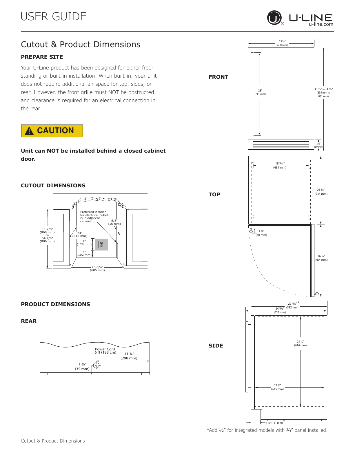
PREPARE SITE
Your U-Line product has been designed for either free-
standing or built-in installation. When built-in, your unit
does not require additional air space for top, sides, or
rear. However, the front grille must NOT be obstructed,
and clearance is required for an electrical connection in
the rear.
CAUTION
!
Unit can NOT be installed behind a closed cabinet
door.
CUTOUT DIMENSIONS
PRODUCT DIMENSIONS
REAR
FRONT
TOP
SIDE
4"
(102 mm)
7"
(178 mm)
33-7/8"
(860 mm)
to
34-7/8"
(886 mm)
23-3/4"
(605 mm)
Preferred location
for electrical outlet
is in adjacent
cabinet.
24"
(610 mm)
5/8"
(16 mm)
Power Cord
6 ft (183 cm)
1 ⁄”
(35 mm)
11 ¾”
(298 mm)
23 ⁄”
(600 mm)
3 ½”
(89 mm)
33 ⁄”
to
34 ⁄”
(855 mm
to
881 mm)
28”
(711 mm)
1 ⁄”
(48 mm)
18 ⁄”
(481 mm)
26 ⁄”
(664 mm)
21 ⁄”
(535 mm)
*
*
*Add 1⁄2” for integrated models with 3⁄4” panel installed.
8
USER GUIDE
Side-by-Side Installation
u-line.com
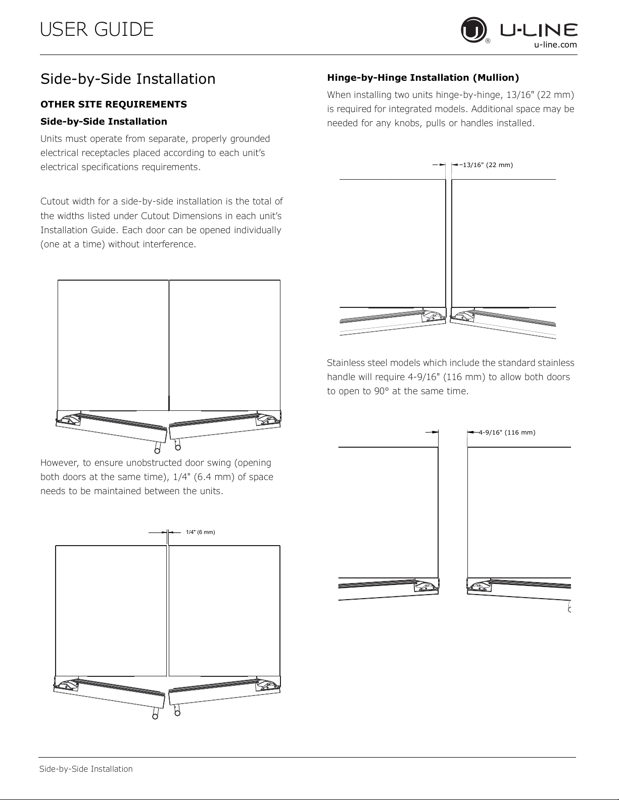
Side-by-Side Installation
OTHER SITE REQUIREMENTS
Side-by-Side Installation
Units must operate from separate, properly grounded
electrical receptacles placed according to each unit’s
electrical specifications requirements.
Cutout width for a side-by-side installation is the total of
the widths listed under Cutout Dimensions in each unit’s
Installation Guide. Each door can be opened individually
(one at a time) without interference.
However, to ensure unobstructed door swing (opening
both doors at the same time), 1/4" (6.4 mm) of space
needs to be maintained between the units.
Hinge-by-Hinge Installation (Mullion)
When installing two units hinge-by-hinge, 13/16" (22 mm)
is required for integrated models. Additional space may be
needed for any knobs, pulls or handles installed.
Stainless steel models which include the standard stainless
handle will require 4-9/16" (116 mm) to allow both doors
to open to 90° at the same time.
1/4" (6 mm)
13/16" (22 mm)
4-9/16" (116 mm)
9
USER GUIDE
u-line.com
Anti-Tip Bracket
Anti-Tip Bracket
Use one of the methods below to secure the unit
CABINET/COUNTER ANTI-TIP INSTALLATION
(For built-in applications)
1. Slide unit out so screws on front of unit are easily
accessible.
2. Remove the two screws from the front of the unit.
3. Bend bracket along one of the perforations to allow
attachment to the desired adjoining surface.
4. Gently push unit into position. Be careful not to
entangle the electrical cord or water line, if applicable.
5. Check to be sure the unit is level from front to back
and side to side. Make any necessary adjustments.
The unit’s top surface should be approximately ”
(3 mm) below the countertop.
6. Secure bracket to adjoining surface.
FLOOR MOUNTED ANTI-TIP INSTALLATION
(For free-standing applications)
1. Locate two anti-tip brackets included with the kit.
2. Place the unit into the area where it will be installed.
test to make sure the door opens and closes freely.
3.
center of the unit.
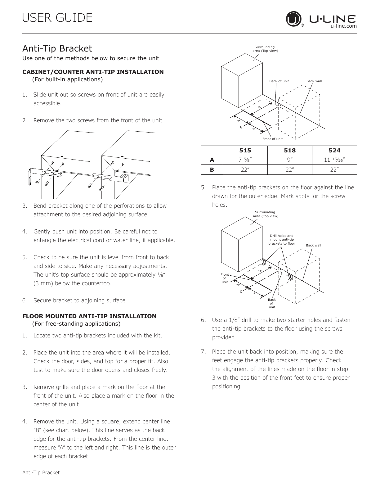
4. Remove the unit. Using a square, extend center line
“B” (see chart below). This line serves as the back
edge for the anti-tip brackets. From the center line,
edge of each bracket.
C
L
Back wall
Back of unit
Front of unit
Surrounding
area (Top view)
A
A
B
515 518 524
A 7 9” 11 ”
B 22” 22” 22”
5.
drawn for the outer edge. Mark spots for the screw
holes.
C
L
Surrounding
area (Top view)
Drill holes and
mount anti-tip
brackets to floor
Back wall
Front
of
unit
Back
of
unit
A
A
B
6. Use a 1/8” drill to make two starter holes and fasten
provided.
7. Place the unit back into position, making sure the
feet engage the anti-tip brackets properly. Check
3 with the position of the front feet to ensure proper
positioning.
10
USER GUIDE
u-line.com
General Installation
General Installation
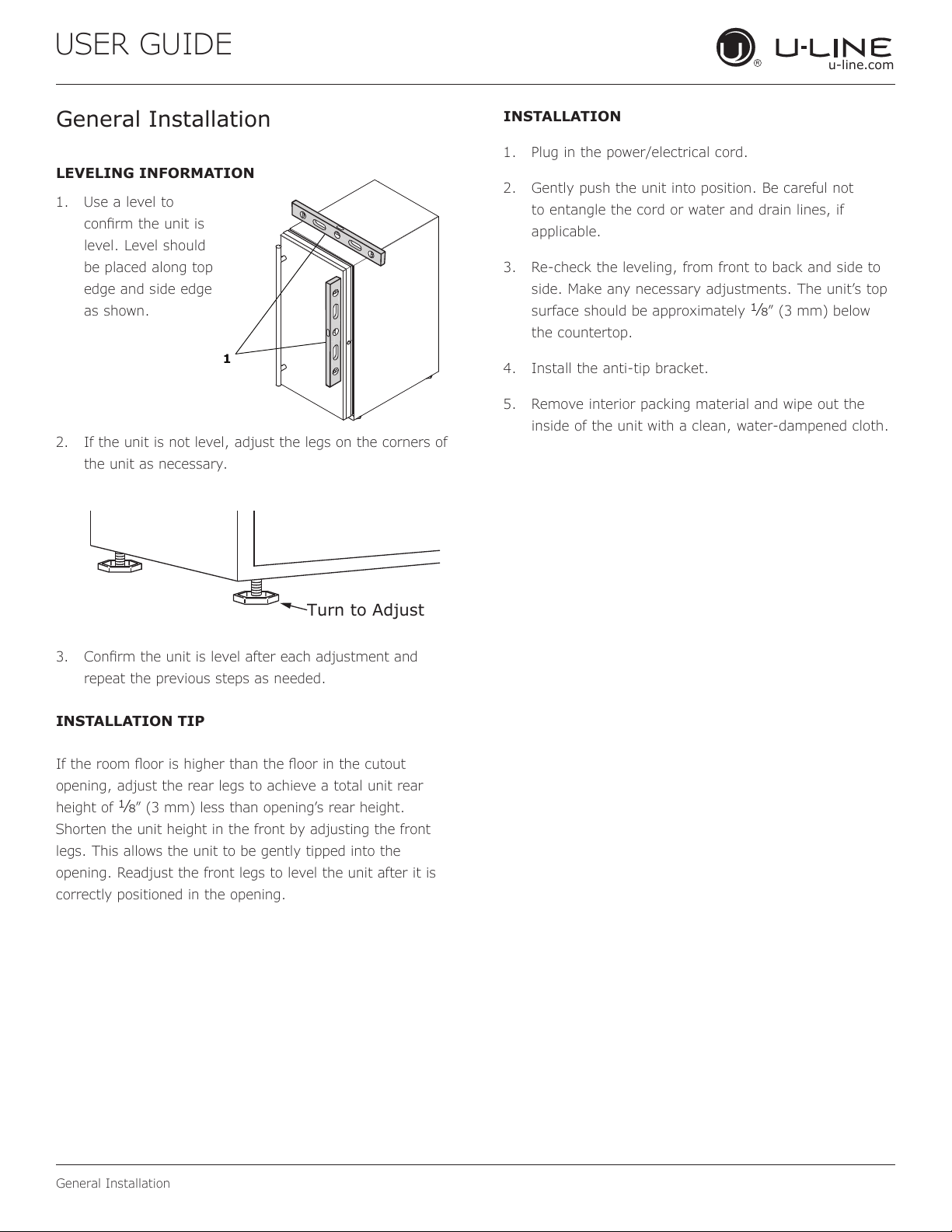
LEVELING INFORMATION
1. Use a level to
conrm the unit is
level. Level should
be placed along top
edge and side edge
as shown.
2. If the unit is not level, adjust the legs on the corners of
the unit as necessary.
3. Conrm the unit is level after each adjustment and
repeat the previous steps as needed.
INSTALLATION TIP
If the room oor is higher than the oor in the cutout
opening, adjust the rear legs to achieve a total unit rear
height of
1⁄8” (3 mm) less than opening’s rear height.
Shorten the unit height in the front by adjusting the front
legs. This allows the unit to be gently tipped into the
opening. Readjust the front legs to level the unit after it is
correctly positioned in the opening.
INSTALLATION
1. Plug in the power/electrical cord.
2. Gently push the unit into position. Be careful not
to entangle the cord or water and drain lines, if
applicable.
3. Re-check the leveling, from front to back and side to
side. Make any necessary adjustments. The unit’s top
surface should be approximately
1⁄8” (3 mm) below
the countertop.
4. Install the anti-tip bracket.
5. Remove interior packing material and wipe out the
inside of the unit with a clean, water-dampened cloth.
1
Turn to Adjust
11
USER GUIDE
Integrated Panel Dimensions
u-line.com
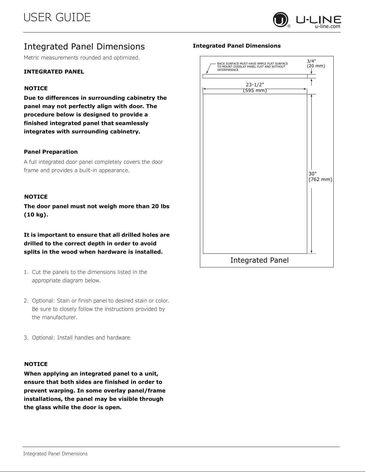
Integrated Panel Dimensions
Metric measurements rounded and optimized.
INTEGRATED PANEL
NOTICE
Due to differences in surrounding cabinetry the
panel may not perfectly align with door. The
procedure below is designed to provide a
finished integrated panel that seamlessly
integrates with surrounding cabinetry.
Panel Preparation
A full integrated door panel completely covers the door
frame and provides a built-in appearance.
NOTICE
The door panel must not weigh more than 20 lbs
(10 kg).
It is important to ensure that all drilled holes are
drilled to the correct depth in order to avoid
splits in the wood when hardware is installed.
1. Cut the panels to the dimensions listed in the
appropriate diagram below.
2. Optional: Stain or finish panel to desired stain or color.
Be sure to closely follow the instructions provided by
the manufacturer.
3. Optional: Install handles and hardware.
NOTICE
When applying an integrated panel to a unit,
ensure that both sides are finished in order to
prevent warping. In some overlay panel/frame
installations, the panel may be visible through
the glass while the door is open.
Integrated Panel Dimensions
BACK SURFACE MUST HAVE AMPLE FLAT SURFACE
TO MOUNT OVERLAY PANEL FLAT AND WITHOUT
INTERFERENCE
23-1/2"
(595 mm)
3/4"
(20 mm)
Integrated Panel
30"
(762 mm)
12
USER GUIDE
Integrated Panel Dimensions
u-line.com
HANDLELESS INTEGRATED DOOR PANEL
The following procedure is designed to provide a finished,
handleless solid panel for a 24" (600 mm) door that
seamlessly integrates with its surrounding cabinetry.
NOTE: Many cabinet manufacturers provide a ready
solution for a handleless, integrated design that can be
easily applied to your model. Consult your cabinet
manufacturer for applicable design and installation details.
The cabinet manufacturer’s solution to this design and
integration detail will often result in an integrated panel
solution wherein the size of the panel may result in a
height dimension taller than what we specify. This can be
achieved provided the additional height is positioned
above the appliance door.
NOTICE
The integrated panel aligns with the surrounding
cabinetry and, due to differences in cabinetry,
may not align perfectly with the door.
The appliance will need up to 34-1/2" (876 mm)
to the underside of the counter to leave room for
leveling adjustments.
A single prepared overlay with insert must not
weigh more than 20 lbs (10 kg).
Integrated Panel Preparation
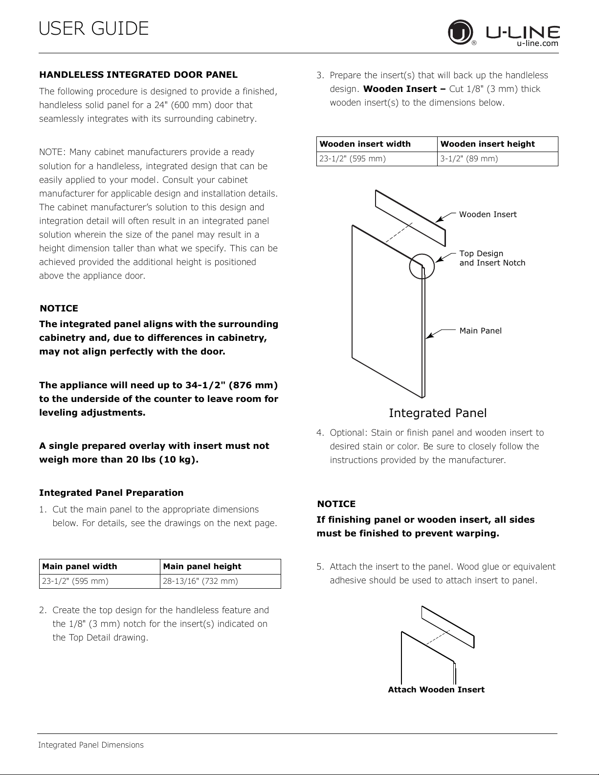
1. Cut the main panel to the appropriate dimensions
below. For details, see the drawings on the next page.
2. Create the top design for the handleless feature and
the 1/8" (3 mm) notch for the insert(s) indicated on
the Top Detail drawing.
3. Prepare the insert(s) that will back up the handleless
design. Wooden Insert – Cut 1/8" (3 mm) thick
wooden insert(s) to the dimensions below.
4. Optional: Stain or finish panel and wooden insert to
desired stain or color. Be sure to closely follow the
instructions provided by the manufacturer.
NOTICE
If finishing panel or wooden insert, all sides
must be finished to prevent warping.
5. Attach the insert to the panel. Wood glue or equivalent
adhesive should be used to attach insert to panel.
Main panel width Main panel height
23-1/2" (595 mm) 28-13/16" (732 mm)
Wooden insert width Wooden insert height
23-1/2" (595 mm) 3-1/2" (89 mm)
Top Design
and Insert Notch
Wooden Insert
Main Panel
Integrated Panel
Attach Wooden Insert
13
USER GUIDE
Integrated Panel Dimensions
u-line.com
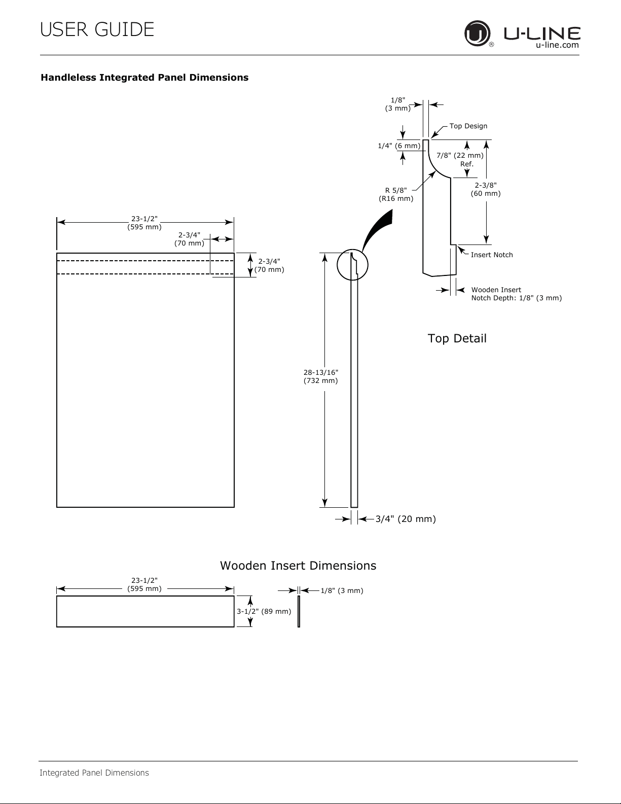
Handleless Integrated Panel Dimensions
3/4" (20 mm)
28-13/16"
(732 mm)
2-3/4"
(70 mm)
2-3/4"
(70 mm)
R 5/8"
(R16 mm)
1/8"
(3 mm)
1/4" (6 mm)
Wooden Insert
Notch Depth: 1/8" (3 mm)
2-3/8"
(60 mm)
7/8" (22 mm)
Ref.
Top Detail
Insert Notch
Top Design
1/8" (3 mm)
3-1/2" (89 mm)
23-1/2"
(595 mm)
Wooden Insert Dimensions
23-1/2"
(595 mm)
14
USER GUIDE
Integrated Panel Dimensions
u-line.com
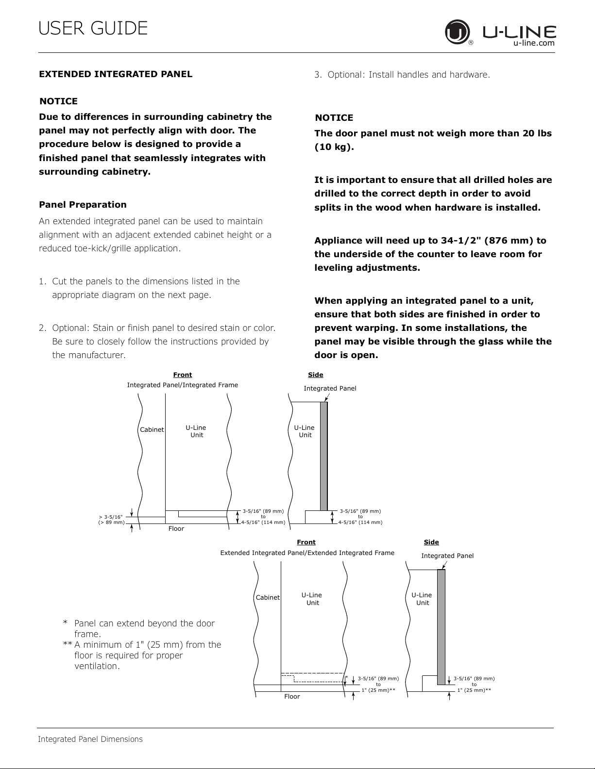
EXTENDED INTEGRATED PANEL
NOTICE
Due to differences in surrounding cabinetry the
panel may not perfectly align with door. The
procedure below is designed to provide a
finished panel that seamlessly integrates with
surrounding cabinetry.
Panel Preparation
An extended integrated panel can be used to maintain
alignment with an adjacent extended cabinet height or a
reduced toe-kick/grille application.
1. Cut the panels to the dimensions listed in the
appropriate diagram on the next page.
2. Optional: Stain or finish panel to desired stain or color.
Be sure to closely follow the instructions provided by
the manufacturer.
3. Optional: Install handles and hardware.
NOTICE
The door panel must not weigh more than 20 lbs
(10 kg).
It is important to ensure that all drilled holes are
drilled to the correct depth in order to avoid
splits in the wood when hardware is installed.
Appliance will need up to 34-1/2" (876 mm) to
the underside of the counter to leave room for
leveling adjustments.
When applying an integrated panel to a unit,
ensure that both sides are finished in order to
prevent warping. In some installations, the
panel may be visible through the glass while the
door is open.
3-5/16" (89 mm)
to
4-5/16" (114 mm)
U-Line
Unit
U-Line
Unit
Integrated Panel
Integrated Panel/Integrated Frame
Front Side
Front Side
3-5/16" (89 mm)
to
4-5/16" (114 mm)
Floor
Cabinet
> 3-5/16"
(> 89 mm)
3-5/16" (89 mm)
to
1" (25 mm)**
U-Line
Unit
Extended Integrated Panel/Extended Integrated Frame
Floor
Cabinet
3-5/16" (89 mm)
to
1" (25 mm)**
*
U-Line
Unit
Integrated Panel
* Panel can extend beyond the door
frame.
** A minimum of 1" (25 mm) from the
floor is required for proper
ventilation.
15
USER GUIDE
Integrated Panel Dimensions
u-line.com
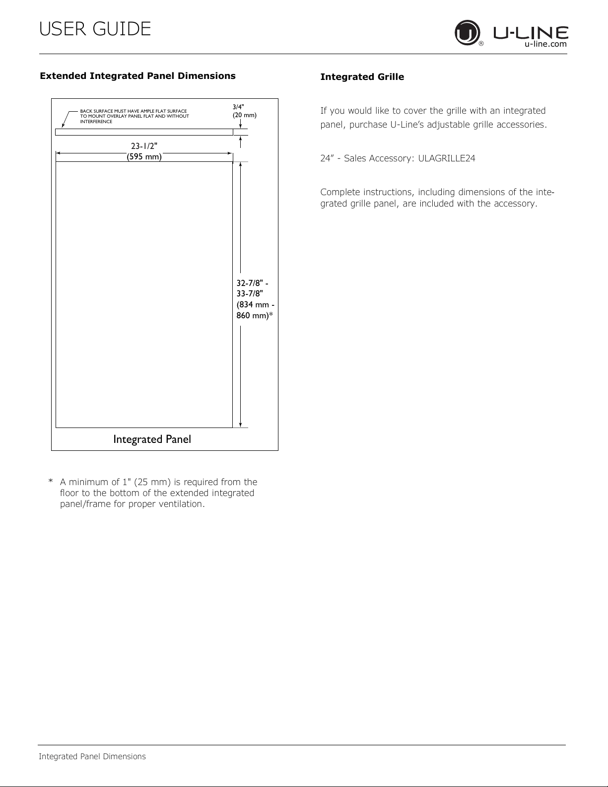
Extended Integrated Panel Dimensions
BACK SURFACE MUST HAVE AMPLE FLAT SURFACE
TO MOUNT OVERLAY PANEL FLAT AND WITHOUT
INTERFERENCE
23-1/2"
(595 mm)
3/4"
(20 mm)
Integrated Panel
32-7/8" -
33-7/8"
(834 mm -
860 mm)*
* A minimum of 1" (25 mm) is required from the
floor to the bottom of the extended integrated
panel/frame for proper ventilation.
Integrated Grille
If you would like to cover the grille with an integrated
panel, purchase U-Line’s adjustable grille accessories.
24” - Sales Accessory: ULAGRILLE24
Complete instructions, including dimensions of the inte-
grated grille panel, are included with the accessory.
16
USER GUIDE
Integrated Panel Installation
u-line.com
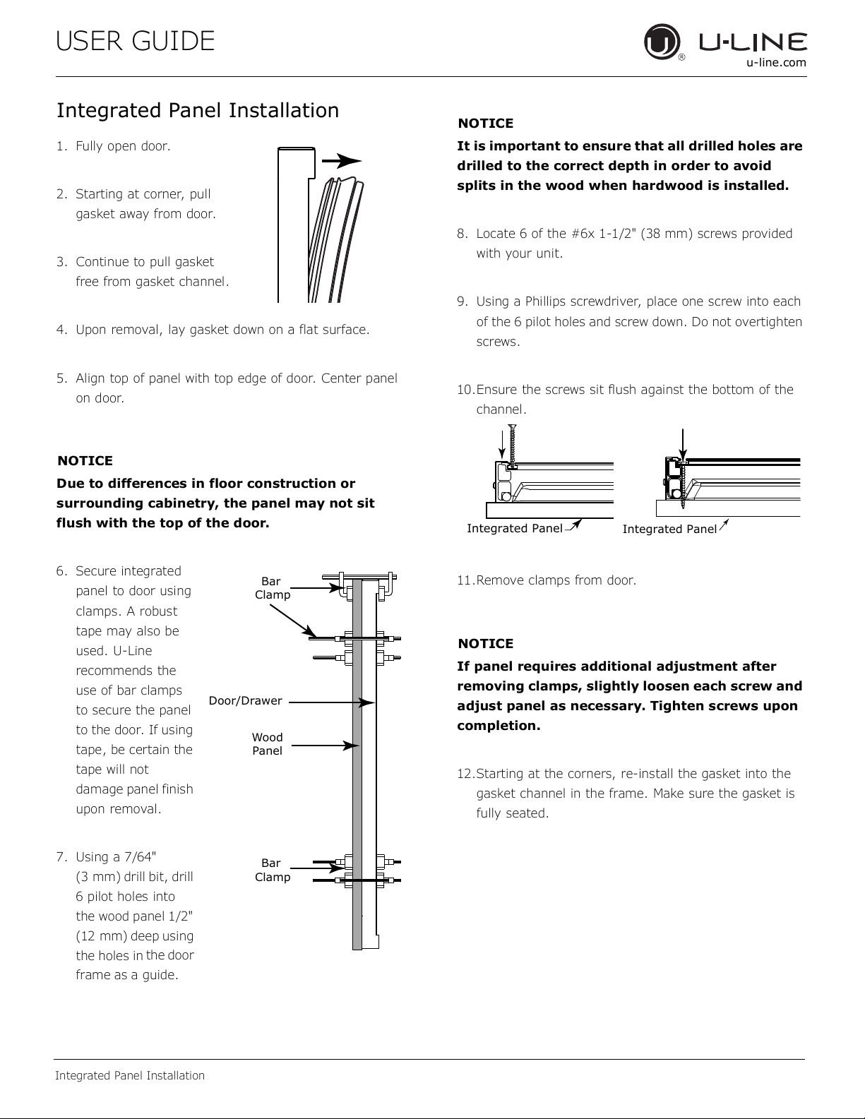
Integrated Panel Installation
1. Fully open door.
2. Starting at corner, pull
gasket away from door.
3. Continue to pull gasket
free from gasket channel.
4. Upon removal, lay gasket down on a flat surface.
5. Align top of panel with top edge of door. Center panel
on door.
NOTICE
Due to differences in floor construction or
surrounding cabinetry, the panel may not sit
flush with the top of the door.
6. Secure integrated
panel to door using
clamps. A robust
tape may also be
used. U-Line
recommends the
use of bar clamps
to secure the panel
to the door. If using
tape, be certain the
tape will not
damage panel finish
upon removal.
7. Using a 7/64"
(3 mm) drill bit, drill
6 pilot holes into
the wood panel 1/2"
(12 mm) deep using
the holes in
the door
frame as a guide.
NOTICE
It is important to ensure that all drilled holes are
drilled to the correct depth in order to avoid
splits in the wood when hardwood is installed.
8. Locate 6 of the #6x 1-1/2" (38 mm) screws provided
with your unit.
9. Using a Phillips screwdriver, place one screw into each
of the 6 pilot holes and screw down. Do not overtighten
screws.
10.Ensure the screws sit flush against the bottom of the
channel.
11.Remove clamps from door.
NOTICE
If panel requires additional adjustment after
removing clamps, slightly loosen each screw and
adjust panel as necessary. Tighten screws upon
completion.
12.Starting at the corners, re-install the gasket into the
gasket channel in the frame. Make sure the gasket is
fully seated.
Wood
Panel
Door/Drawer
Bar
Clamp
Bar
Clamp
Integrated Panel
Integrated Panel
17
USER GUIDE
Grille Installation
u-line.com
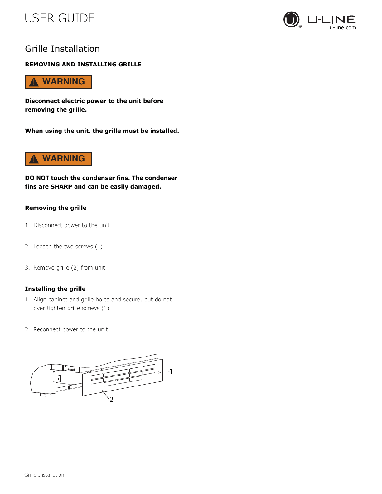
Grille Installation
REMOVING AND INSTALLING GRILLE
WARNING
!
Disconnect electric power to the unit before
removing the grille.
When using the unit, the grille must be installed.
WARNING
!
DO NOT touch the condenser fins. The condenser
fins are SHARP and can be easily damaged.
Removing the grille
1. Disconnect power to the unit.
2. Loosen the two screws (1).
3. Remove grille (2) from unit.
Installing the grille
1. Align cabinet and grille holes and secure, but do not
over tighten grille screws (1).
2. Reconnect power to the unit.
1
2
18
USER GUIDE
Door Swing
u-line.com
Door Swing
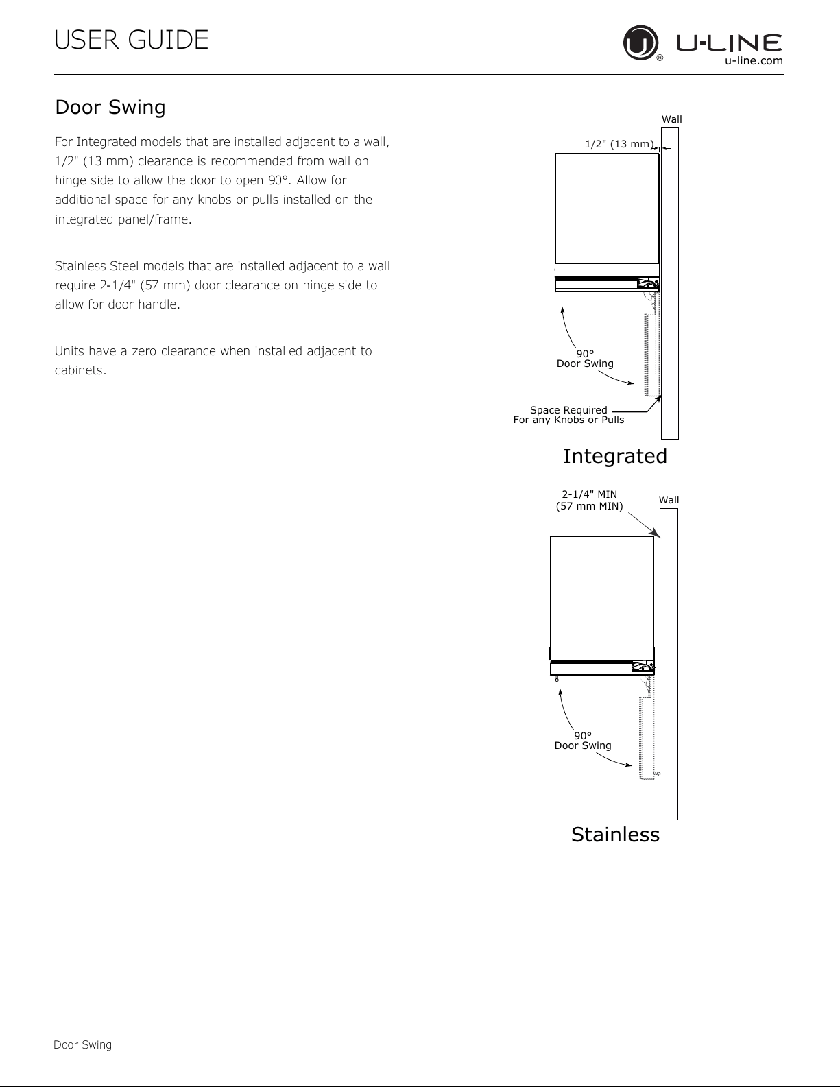
For Integrated models that are installed adjacent to a wall,
1/2" (13 mm) clearance is recommended from wall on
hinge side to allow the door to open 90°. Allow for
additional space for any knobs or pulls installed on the
integrated panel/frame.
Stainless Steel models that are installed adjacent to a wall
require 2- 1/4" (57 mm) door clearance on hinge side to
allow for door handle.
Units have a zero clearance when installed adjacent to
cabinets.
Wall
Wall
90°
Door Swing
90°
Door Swing
Space Required
For any Knobs or Pulls
2-1/4" MIN
(57 mm MIN)
Integrated
Stainless
1/2" (13 mm)
19
USER GUIDE
u-line.com
Door Adjustments
Door Adjustments
DOOR ALIGNMENT AND ADJUSTMENT
Align and adjust the door if it is not level or not sealing
properly. If the door is not sealed, the unit may not cool
properly, or excessive frost or condensation may form in
the interior.
NOTICE
Properly aligned, the door’s gasket should be
rmly in contact with the cabinet all the way
around the door (no gaps). Carefully examine the
door’s gasket to ensure that it is rmly in contact
with the cabinet. Also make sure the door gasket
is not pinched on the hinge side of the door.
Do not attempt to use the door to raise or pivot
your unit. This would put excessive stress on the
hinge system.
Alignment and Adjustment Procedure
1. Open door and remove gasket near the hinges.
2. Using a T-25 Torx bit, loosen each pair of Torx head
screws both the upper and lower hinge plates.
3. Square and align door as necessary.
4. Tighten Torx head screws on hinge.
5. Reinstall gasket into the channel starting at the corner.
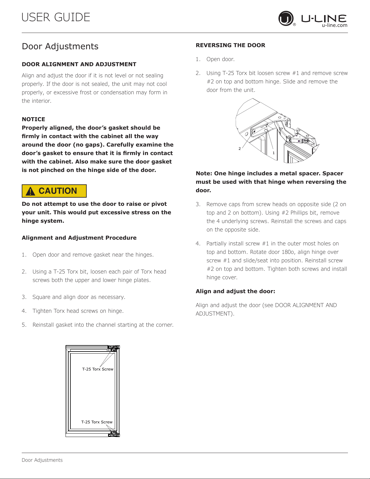
REVERSING THE DOOR
1. Open door.
2. Using T-25 Torx bit loosen screw #1 and remove screw
#2 on top and bottom hinge. Slide and remove the
door from the unit.
Note: One hinge includes a metal spacer. Spacer
must be used with that hinge when reversing the
door.
3. Remove caps from screw heads on opposite side (2 on
top and 2 on bottom). Using #2 Phillips bit, remove
the 4 underlying screws. Reinstall the screws and caps
on the opposite side.
4. Partially install screw #1 in the outer most holes on
top and bottom. Rotate door 180o, align hinge over
screw #1 and slide/seat into position. Reinstall screw
#2 on top and bottom. Tighten both screws and install
hinge cover.
Align and adjust the door:
Align and adjust the door (see DOOR ALIGNMENT AND
ADJUSTMENT).
T-25 Torx Screw
T-25 Torx Screw
2
1
CAUTION
!
20
USER GUIDE
u-line.com
First Use
Temperature displayed reects actual
temperature inside unit.
Initial startup requires no adjustments. When plugged
in, the unit will begin operating under the factory default
settings. If the unit was turned o during installation,
simply press and the unit will immediately switch on. To
turn the unit o, press .
If the temperature displayed is dierent than selected, the
unit is progressing towards the selected temperature. Time
to reach set point varies based upon ambient temperature,
temperature of product loaded, door openings, etc. U-Line
recommends allowing the unit to reach set points before
loading.
NOTICE
First Use
21
USER GUIDE
u-line.com
Control Operation
Control Operation
CONTROL FUNCTION GUIDE
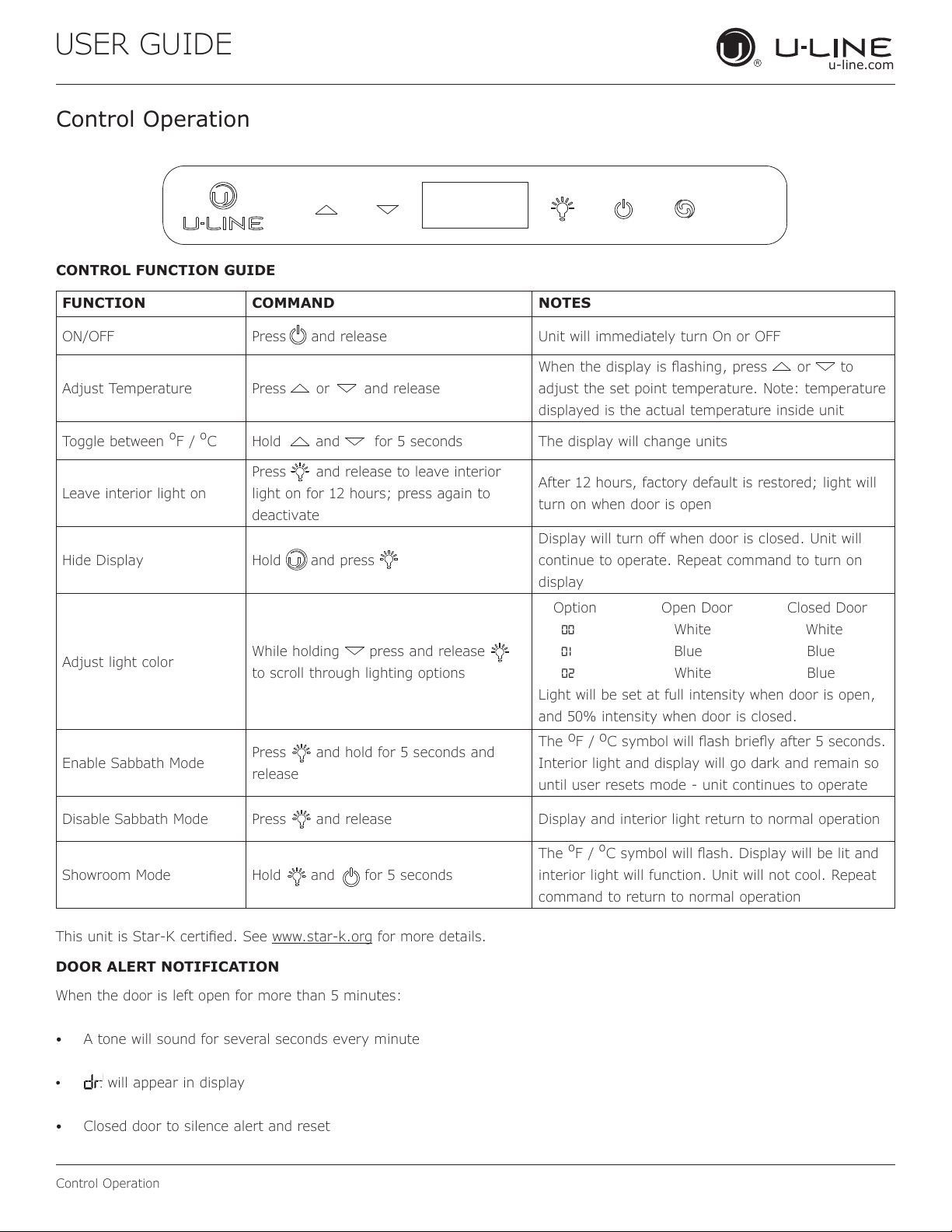
FUNCTION COMMAND NOTES
ON/OFF Press and release Unit will immediately turn On or OFF
Adjust Temperature Press or and release
When the display is ashing, press or to
adjust the set point temperature. Note: temperature
displayed is the actual temperature inside unit
Toggle between
º
F /
º
C Hold and for 5 seconds The display will change units
Leave interior light on
Press and release to leave interior
light on for 12 hours; press again to
deactivate
After 12 hours, factory default is restored; light will
turn on when door is open
Hide Display Hold and press
Display will turn o when door is closed. Unit will
continue to operate. Repeat command to turn on
display
Adjust light color
While holding press and release
to scroll through lighting options
Option Open Door Closed Door
00 White White
01 Blue Blue
02 White Blue
Light will be set at full intensity when door is open,
and 50% intensity when door is closed.
Enable Sabbath Mode
Press and hold for 5 seconds and
release
The
o
F /
o
C symbol will ash briey after 5 seconds.
Interior light and display will go dark and remain so
until user resets mode - unit continues to operate
Disable Sabbath Mode Press and release Display and interior light return to normal operation
Showroom Mode Hold and for 5 seconds
The
º
F /
º
C symbol will ash. Display will be lit and
interior light will function. Unit will not cool. Repeat
command to return to normal operation
This unit is Star-K certied. See www.star-k.org for more details.
DOOR ALERT NOTIFICATION
When the door is left open for more than 5 minutes:
• A tone will sound for several seconds every minute
•
will appear in display
• Closed door to silence alert and reset
22
USER GUIDE
u-line.com
Airow & Product Loading
Restricting airow may result in poor product
performance, product failure, and uneven internal
temperatures and may freeze contents.
• Do not block the front grille - no additional clearance
around sides, top or rear of unit is needed for ventilation
• Do not install behind a closed door
• When loading, leave space between internal fans, vents,
and side walls to allow air to circulate freely
NOTICE
AIRFLOW
External
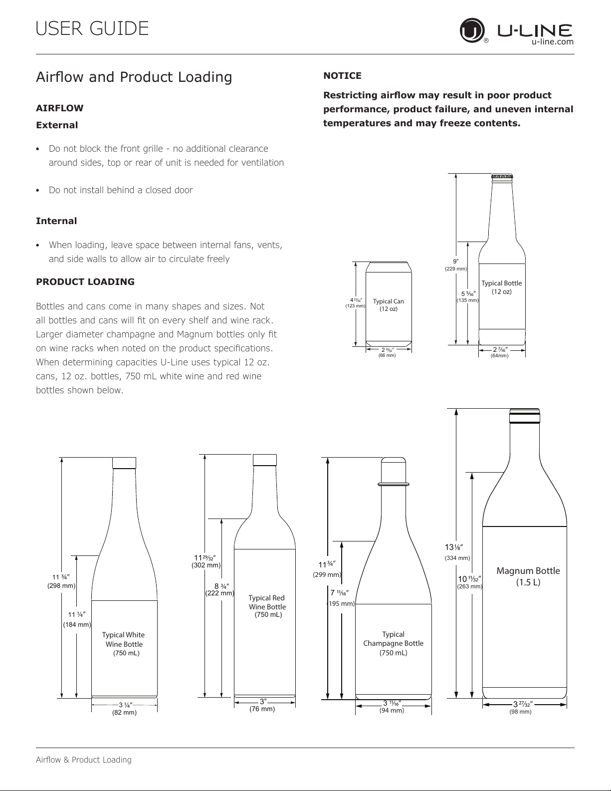
PRODUCT LOADING
Bottles and cans come in many shapes and sizes. Not
all bottles and cans will t on every shelf and wine rack.
Larger diameter champagne and Magnum bottles only t
on wine racks when noted on the product specications.
When determining capacities U-Line uses typical 12 oz.
cans, 12 oz. bottles, 750 mL white wine and red wine
bottles shown below.
Airow and Product Loading
Typical Can
(12 oz)
4
(123 mm)
(66 mm)
2
⁄”
⁄”
Typical Bottle
(12 oz)
9”
5
2
⁄”
⁄”
(135 mm)
(64mm)
(229 mm)
Typical White
Wine Bottle
11
(298 mm)
(750 mL)
3
¾”
(184 mm)
(82 mm)
11
¼”
¼”
Typical Red
Wine Bottle
11
(302 mm)
8
3”
⁄”
¾”
(222 mm)
(750 mL)
(76 mm)
Typical
Champagne Bottle
(750 mL)
3 ⁄”
7
¾”
⁄”
(299 mm)
(94 mm)
(195 mm)
11
Magnum Bottle
(1.5 L)
13
10
3
⁄”
(334 mm)
⁄”
(263 mm)
⁄”
(98 mm)
Internal
23
USER GUIDE
u-line.com
Interior Adjustments
Interior Adjustments
All 5 Class models feature side mounted rack supports with
19 adjustment positions.
All refrigerators ship with 3 Slide and Secure storage bins.
Remove and reposition as desired.
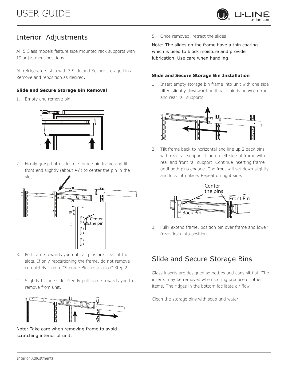
Slide and Secure Storage Bin Removal
1. Empty and remove bin.
2. Firmly grasp both sides of storage bin frame and lift
front end slightly (about 1/4”) to center the pin in the
slot.
3. Pull frame towards you until all pins are clear of the
slots. If only repositioning the frame, do not remove
completely - go to “Storage Bin Installation” Step 2.
4. Slightly tilt one side. Gently pull frame towards you to
remove from unit.
Note: Take care when removing frame to avoid
scratching interior of unit.
5. Once removed, retract the slides.
Note: The slides on the frame have a thin coating
which is used to block moisture and provide
lubrication. Use care when handling.
Slide and Secure Storage Bin Installation
1. Insert empty storage bin frame into unit with one side
tilted slightly downward until back pin is between front
and rear rail supports.
2. Tilt frame back to horizontal and line up 2 back pins
with rear rail support. Line up left side of frame with
rear and front rail support. Continue inserting frame
until both pins engage. The front will set down slightly
and lock into place. Repeat on right side.
3. Fully extend frame, position bin over frame and lower
(rear rst) into position.
Slide and Secure Storage Bins
Glass inserts are designed so bottles and cans sit at. The
inserts may be removed when storing produce or other
items. The ridges in the bottom facilitate air ow.
Clean the storage bins with soap and water.
Center
the pin
Center
the pins
Front Pin
Back Pin
24
USER GUIDE
Cleaning
u-line.com
Cleaning
Stainless Models
Stainless door panels and handles can discolor when
exposed to chlorine gas, pool chemicals, saltwater or
cleaners with bleach.
Keep your stainless unit looking new by cleaning with a
good quality all-in-one stainless steel cleaner and polish
monthly. For best results use Claire
®
Stainless Steel
Polish and Cleaner. Comparable products are acceptable.
Frequent cleaning will remove surface contamination that
could lead to rust. Some installations may require cleaning
weekly.
Do not clean with steel wool pads.
Do not use stainless steel cleaners or polishes on
any glass surfaces.
Clean any glass surfaces with a non-chlorine glass
cleaner.
Do not use cleaners not specifically intended for
stainless steel on stainless steel surfaces (this
includes glass, tile and counter cleaners).
If any surface discoloring or rusting appears, clean it
quickly with Bon-Ami
®
or Barkeepers Friend Cleanser
®
and a nonabrasive cloth. Always clean with the grain.
Always finish with Claire
®
Stainless Steel Polish and
Cleaner or comparable product to prevent further
problems.
Using abrasive pads such as Scotchbrite™ will
cause the graining in the stainless steel to
become blurred.
Rust not cleaned up promptly can penetrate the
surface of the stainless steel and complete
removal of the rust may not be possible.
Integrated Models
To clean integrated panels, use household cleaner per the
cabinet manufacturer’s recommendation.
INTERIOR CLEANING
Disconnect power to the unit.
Clean the interior and all removed components using a
mild nonabrasive detergent and warm water solution
applied with a soft sponge or non-abrasive cloth.
Rinse the interior using a soft sponge and clean water.
Do not use any solvent-based or abrasive
cleaners. These types of cleaners may transfer taste to
the interior products and damage or discolor the lining.
DEFROSTING
Under normal conditions this unit does not require manual
defrosting. Minor frost on the rear wall or visible through
the evaporator plate vents is normal and will melt during
each off cycle.
If there is excessive build-up of 1/4" (6 mm) or more,
manually defrost the unit.
Ensure the door is closing and sealing properly.
High ambient temperature and excessive humidity can
also produce frost.
CAUTION
!
DO NOT use an ice pick or other sharp
instrument to help speed up defrosting. These
instruments can puncture the inner lining or
damage the cooling unit. DO NOT use any type of
heater to defrost. Using a heater to speed up
defrosting can cause personal injury and
damage to the inner lining.
25
USER GUIDE
Cleaning
u-line.com
NOTICE
The drain pan was not designed to capture the
water created when manually defrosting. To
prevent water from overflowing the drain pan
and possibly damaging water sensitive flooring,
the unit must be removed from cabinetry.
To defrost:
1. Disconnect power to the unit.
2. Remove all products from the interior.
3. Prop the door in an open position (2 in. [50 mm]
minimum).
4. Allow the frost to melt naturally.
5. After the frost melts completely clean the interior and
all removed components. (See INTERIOR CLEANING).
6. When the interior is dry, reconnect power and turn unit
on.
26
USER GUIDE
u-line.com
Cleaning Condenser
Cleaning Condenser
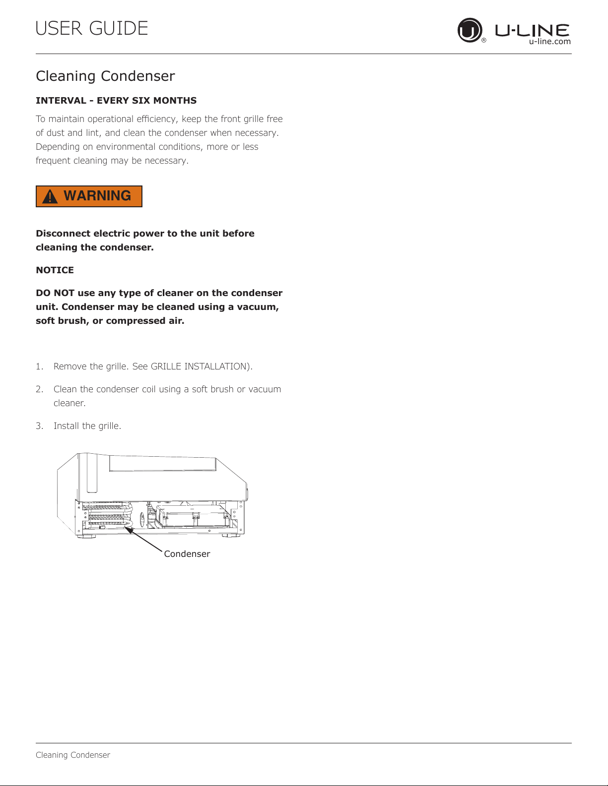
INTERVAL - EVERY SIX MONTHS
To maintain operational eciency, keep the front grille free
of dust and lint, and clean the condenser when necessary.
Depending on environmental conditions, more or less
frequent cleaning may be necessary.
WARNING
!
Disconnect electric power to the unit before
cleaning the condenser.
NOTICE
DO NOT use any type of cleaner on the condenser
unit. Condenser may be cleaned using a vacuum,
soft brush, or compressed air.
1. Remove the grille. See GRILLE INSTALLATION).
2. Clean the condenser coil using a soft brush or vacuum
cleaner.
3. Install the grille.
Condenser
27
USER GUIDE
Extended Non-Use
u-line.com
Extended Non-Use
VACATION/HOLIDAY, PROLONGED SHUTDOWN
The following steps are recommended for periods of
extended non-use:
1. Remove all consumable content from the unit.
2. Disconnect the power cord from its outlet/socket and
leave it disconnected until the unit is returned to
service.
3. If ice is on the evaporator, allow ice to thaw naturally.
4. Clean and dry the interior of the unit. Ensure all water
has been removed from the unit.
5. The door must remain open to prevent formation of
mold and mildew. Open door a minimum of 2"
(50 mm) to provide the necessary ventilation.
WINTERIZATION
If the unit will be exposed to temperatures of 40°F (5°C)
or less, the steps above must be followed.
For questions regarding winterization, please
call U-Line at 414.354.0300.
CAUTION
!
Damage caused by freezing temperatures is not
covered by the warranty.
28
USER GUIDE
u-line.com
Troubleshooting
u-line.com
If you think your U-Line product is malfunctioning, read the
CONTROL OPERATION section to clearly understand the
function of the control.
If the problem persists, read the NORMAL OPERATING
SOUNDS and TROUBLESHOOTING GUIDE sections below
to help you quickly identify common problems and possible
causes and remedies. Most often, this will resolve the
problem without the need to call for service.
If you do not understand a troubleshooting remedy, or your
product needs service, contact U-Line Corporation directly
at +1.800.779.2547.
When you call, you will need your product Model and Serial
Numbers. This information appears on the Model and Serial
number plate located on the upper right or rear wall of the
interior of your product.
All models incorporate rigid foam insulated cabinets to
provide high thermal eciency and maximum sound
reduction for its internal working components. Despite this
technology, your model may make sounds that are
unfamiliar.
Normal operating sounds may be more noticeable because
of the unit’s environment. Hard surfaces such as cabinets,
wood, vinyl or tiled oors and paneled walls have a
tendency to reect normal appliance operating noises.
Listed below are common refrigeration components with a
brief description of the normal operating sounds they
make. NOTE: Your product may not contain all the
components listed.
• Compressor: The compressor makes a hum or pulsing
sound that may be heard when it operates.
BEFORE CALLING FOR SERVICE
TROUBLESHOOTING GUIDE
ELECTROCUTION HAZARD. Never attempt to
repair or perform maintenance on the unit
before disconnecting the main electrical power.
Troubleshooting - What to check when problems occur:
NORMAL OPERATING SOUNDS
IF SERVICE IS REQUIRED
Troubleshooting
• Evaporator: Refrigerant owing through an evaporator
may sound like boiling liquid.
• Condenser Fan: Air moving through a condenser may
be heard.
• Automatic Defrost Drain Pan: Water may be heard
dripping or running into the drain pan when the unit is
in the defrost cycle.
DANGER
!
Problem Possible Cause and Remedy
Interior Light
Does Not
Illuminate
If the unit is cooling, it may be in
Sabbath mode.
Light Remains
on When Door
Is Closed.
Turn o light switch if equipped.
Adjust light actuator bracket on bottom
of door.
Unit Develops
Frost on
Internal
Surfaces.
Ensure the door is closing and sealing
properly.
Unit Develops
Condensation
on External
Surfaces.
The unit is exposed to excessive
humidity. Moisture will dissipate as
humidity levels decrease.
Product is Not
Cold Enough
Air temperature does not indicate
product temperature. See CHECKING
PRODUCT TEMPERATURE below.
Adjust the temperature to a cooler set
point.
Ensure unit is not located in excessive
ambient temperatures or in direct
sunlight.
Ensure the door is closing and sealing
properly.
Ensure the interior light has not
remained on too long.
Ensure nothing is blocking the front
grille, found at the bottom of the unit.
Ensure the condenser coil is clean and
free of any dirt or lint build-up.
29
USER GUIDE
u-line.comu-line.com
Troubleshooting
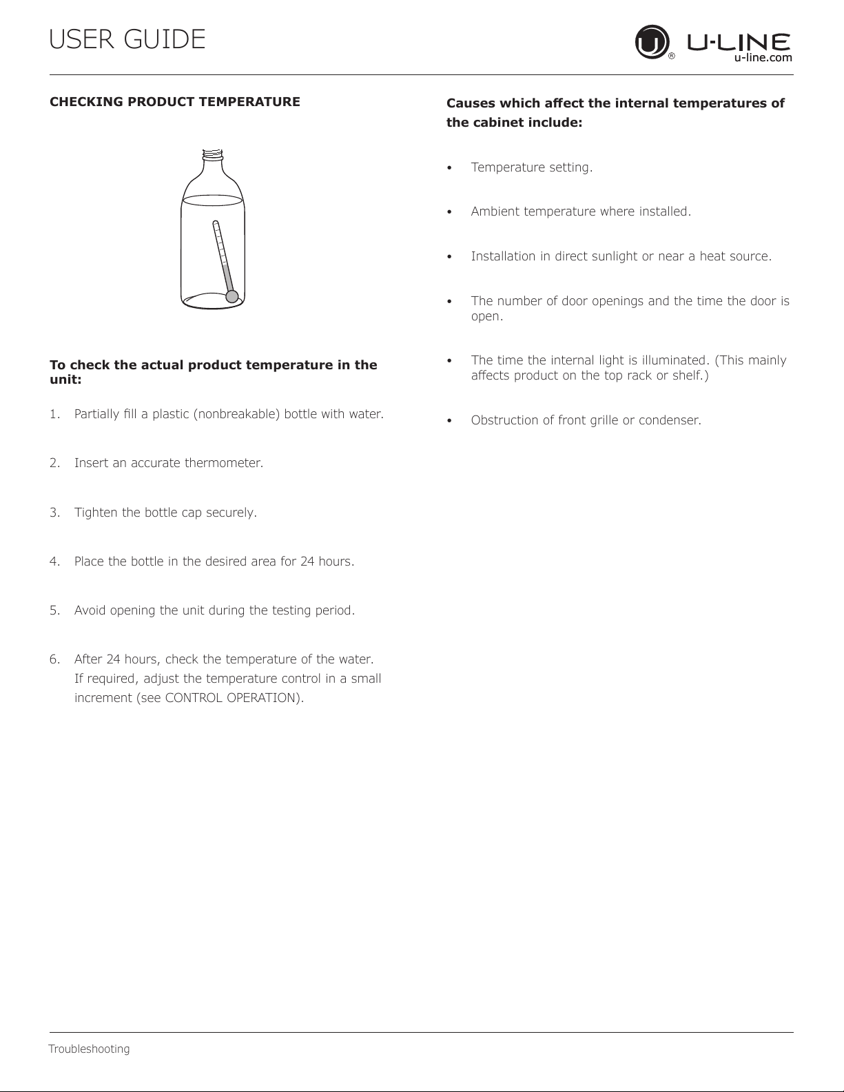
CHECKING PRODUCT TEMPERATURE
To check the actual product temperature in the
unit:
1. Partially ll a plastic (nonbreakable) bottle with water.
2. Insert an accurate thermometer.
3. Tighten the bottle cap securely.
4. Place the bottle in the desired area for 24 hours.
5. Avoid opening the unit during the testing period.
6. After 24 hours, check the temperature of the water.
If required, adjust the temperature control in a small
increment (see CONTROL OPERATION).
Causes which aect the internal temperatures of
the cabinet include:
• Temperature setting.
• Ambient temperature where installed.
• Installation in direct sunlight or near a heat source.
• The number of door openings and the time the door is
open.
• The time the internal light is illuminated. (This mainly
aects product on the top rack or shelf.)
• Obstruction of front grille or condenser.
30
USER GUIDE
u-line.com
Wire Diagram
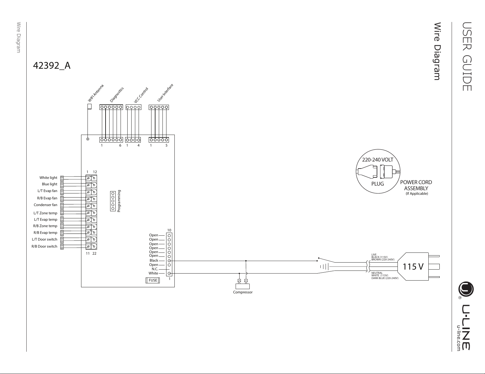
Wire Diagram
115 V
Open
Open
Open
Open
Open
Open
Black
N.C.
White
FUSE
11
10
22
1
1
12
White light
Blue light
L/T Evap fan
R/B Evap fan
Condenser fan
L/T Zone temp
L/T Door switch
R/B Door switch
L/T Evap temp
R/B Zone temp
R/B Evap temp
Compressor
Open
Programming
WIFI Antenna
Diagnostics
VCC Control
User Interface
42392_A
1 51 6 1 4
(If Applicable)
POWER CORD
ASSEMBLY
220-240 VOLT
PLUG
LIVE
BLACK (115V)
BROWN (220-240V)
NEUTRAL
WHITE (115V)
DARK BLUE (220-240V)
31
USER GUIDE
u-line.com
Product Liability
Product Liability
Field service technicians are authorized to make an initial
assessment in the event of reported damages. If there are
any questions about the process involved, the technician
should call U-Line for further explanation.
While inspecting for defects or installation issues, photos
should be taken to document any damages or issues found.
During the assessment, if the service technician is able to
nd the source of the damage and it can be resolved by
replacement of a part, the servicer is authorized to replace
the part in question. The part that caused the damage
must be returned to U-Line in its entirety. The part must
be clearly labeled with the serial number of the unit it was
removed from, the date, and the servicer who removed the
part.
If the service technician determines the damage is the
result of installation issues (water connection/drain, etc.),
the consumer would be notied and the issues shall be
resolved at the direction of the consumer.
If damage is evident and the service technician is
unable to nd the source, U-Line must be contacted at
1.800.799.2547 for further direction.
8900 N. 55th Street • Milwaukee, WI 53223
T: +1.414.354.0300 • F: +1.414.354.5696
Website: www.u-line.com
Right product. Right place.
Right temperature Since 1962.
32
USER GUIDE
u-line.com
Warranty Claims
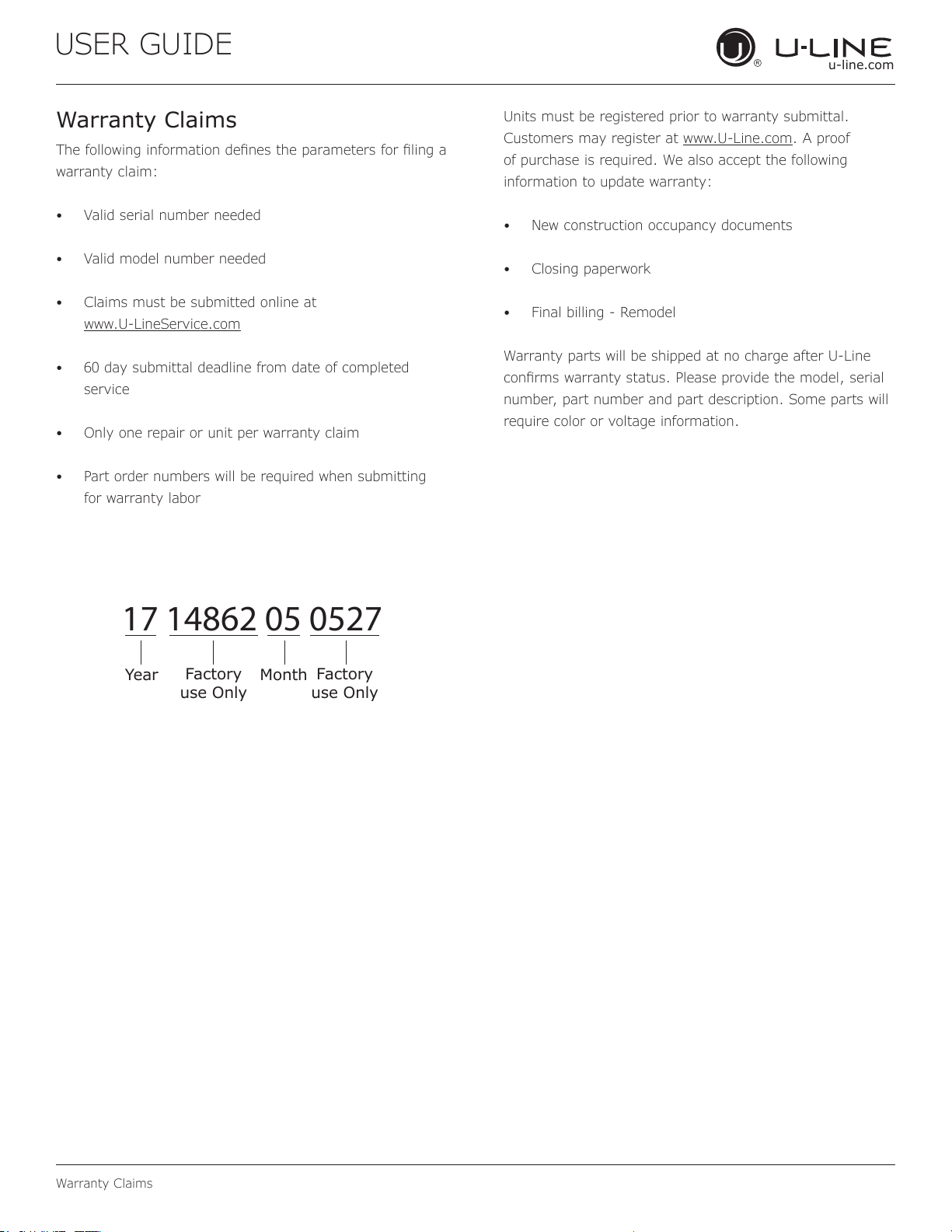
The following information denes the parameters for ling a
warranty claim:
• Valid serial number needed
• Valid model number needed
• Claims must be submitted online at
www.U-LineService.com
• 60 day submittal deadline from date of completed
service
• Only one repair or unit per warranty claim
• Part order numbers will be required when submitting
for warranty labor
Units must be registered prior to warranty submittal.
Customers may register at www.U-Line.com. A proof
of purchase is required. We also accept the following
information to update warranty:
• New construction occupancy documents
• Closing paperwork
• Final billing - Remodel
Warranty parts will be shipped at no charge after U-Line
conrms warranty status. Please provide the model, serial
number, part number and part description. Some parts will
require color or voltage information.
Warranty Claims
17 14862 05 0527
Year
Factory
use Only
Factory
use Only
Month
33
USER GUIDE
u-line.com
Parts
16
13
1
2
21
27
26
18
9
15
23
8
17
12
3
14
4
25
7
11
5
20
6
22
19
10
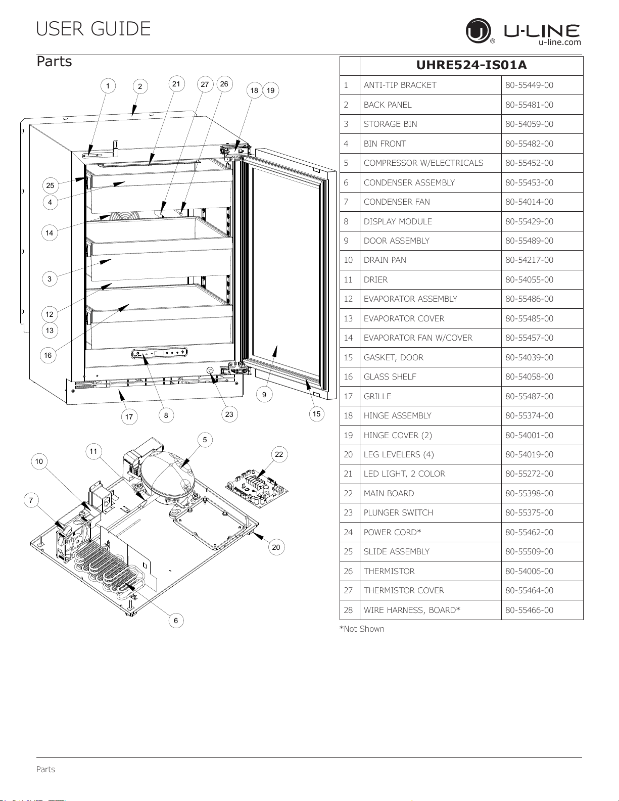
Parts
UHRE524-IS01A
1 ANTI-TIP BRACKET 80-55449-00
2 BACK PANEL 80-55481-00
3 STORAGE BIN 80-54059-00
4 BIN FRONT 80-55482-00
5 COMPRESSOR W/ELECTRICALS 80-55452-00
6 CONDENSER ASSEMBLY 80-55453-00
7 CONDENSER FAN 80-54014-00
8 DISPLAY MODULE 80-55429-00
9 DOOR ASSEMBLY 80-55489-00
10 DRAIN PAN 80-54217-00
11 DRIER 80-54055-00
12 EVAPORATOR ASSEMBLY 80-55486-00
13 EVAPORATOR COVER 80-55485-00
14 EVAPORATOR FAN W/COVER 80-55457-00
15 GASKET, DOOR 80-54039-00
16 GLASS SHELF 80-54058-00
17 GRILLE 80-55487-00
18 HINGE ASSEMBLY 80-55374-00
19 HINGE COVER (2) 80-54001-00
20 LEG LEVELERS (4) 80-54019-00
21 LED LIGHT, 2 COLOR 80-55272-00
22 MAIN BOARD 80-55398-00
23 PLUNGER SWITCH 80-55375-00
24 POWER CORD* 80-55462-00
25 SLIDE ASSEMBLY 80-55509-00
26 THERMISTOR 80-54006-00
27 THERMISTOR COVER 80-55464-00
28 WIRE HARNESS, BOARD* 80-55466-00
*Not Shown
34
USER GUIDE
u-line.com
Ordering Replacement Parts
Parts may be ordered online at www.U-Line.com
See our contact information below:
www.U-LineService.com (with service login)
Phone Number: +1.800.779.2547
NOTICE
Use only genuine U-Line replacement parts.
The use of non-U-Line parts can reduce speed
of ice production, cause water to overow from
ice maker mold, damage the unit, and void the
warranty.
Warranty parts will be shipped at no charge after U-Line
conrms warranty status. Please provide the model, serial
number, part number and part description. Some parts will
require color or voltage information.
If U-Line requires the return of original parts, we will
inform you when the parts order is taken. This
requirement will be noted on your packing list. A
prepaid shipping label will be emailed to you. Please
enclose a copy of the parts packing list and be sure the
model and serial numbers are legible on the paperwork.
Tag the part with the reported defect.
Customers and non-authorized servicers may order non-
warranty parts at www.u-line.com. Authorized servicers
with a servicer login may order non-warranty parts at
www.u-lineservice.com.
Ordering Replacement Parts
35
USER GUIDE
u-line.com
R-600A Specications
R-600A Specifications
For R-600a refrigerant service tips and more videos, go
to: www.u-line.com/videos
.
WARNING
!
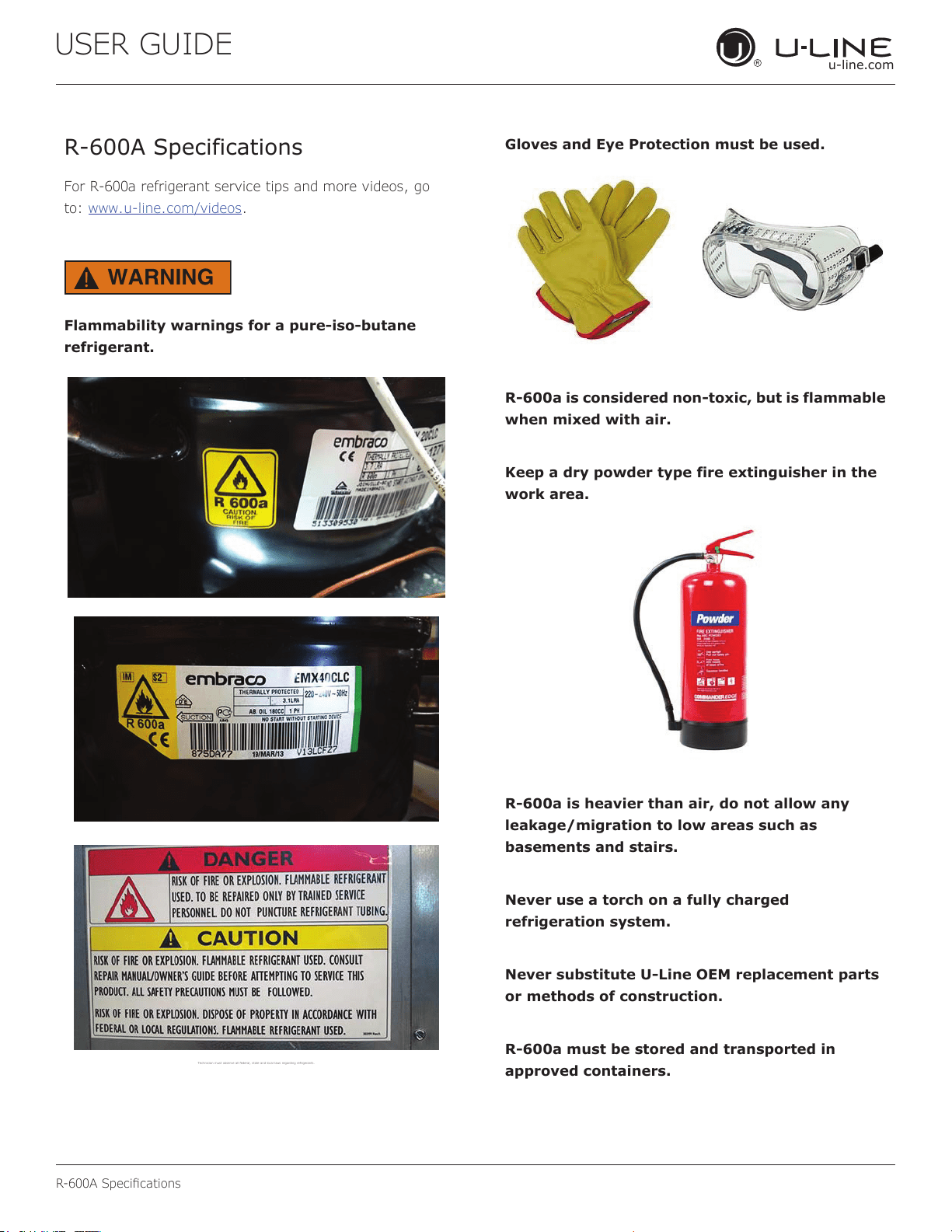
Flammability warnings for a pure-iso-butane
refrigerant.
Technician m ust observe al l federal, st ate and local la ws regarding r efrigerants .
Gloves and Eye Protection must be used.
R-600a is considered non-toxic, but is flammable
when mixed with air.
Keep a dry powder type fire extinguisher in the
work area.
R-600a is heavier than air, do not allow any
leakage/migration to low areas such as
basements and stairs.
Never use a torch on a fully charged
refrigeration system.
Never substitute U-Line OEM replacement parts
or methods of construction.
R-600a must be stored and transported in
approved containers.
36
R-600A Specications
USER GUIDE
u-line.com
WARNING
!
Only skilled and well trained service technicians
permitted to service R-600a equipped products.
All tools and equipment must be approved for
use with R-600a refrigerant.
Local, state and federal laws, standards must be
observed along with proper certification and
licensing.
Ventilation is required during servicing.
No conversions to R-600a from any other
refrigerants. OEM R-600a equipped unit only.
Service area must be free of ignition sources.
No smoking is allowed in the service area.
All replacement electrical components must be
OEM and installed properly (sealed and
covered).
If the evaporator is cold prior to service, it must
be thawed prior to service.
When using a vacuum pump, start pump before
opening refrigeration system.
Vacuum pump and recovery equipment should
be at least 10 feet from the work area.
It is recommended that a simple LPG gas
detector is on site during service.
Ensure that all R-600a is removed from the
system prior to brazing any part of the sealed
system.
Only a clean, dry leak free system should be
charged with R-600a.
R-600A SPECIFICATIONS/LABELING
R-600a equipped products are labeled (both the unit and
the compressor).
R-600a is colorless and odorless.
R-600a is considered non-toxic, but is flammable when
mixed with air.
Do not remove or alter any R-600a labeling on the
product.
Use only a refrigerant grade R-600a from a properly
labeled container.
RECOVERING/RECLAIMING R-600A
(R-600a has been exempted from recovery/reclaiming
requirements by the US EPA)
Recovery/Reclaiming equipment must be approved for use
with R-600a.
Ensure the evaporator is at room temperature prior to
recovery/reclaiming R-600a.
Use a common piercing pliers or piercing valve to remove
R-600a from the compressor process tube. (Note: Piercing
devices must not be left on the system and must be
replaced with a Schrader type valve.)
37
USER GUIDE
u-line.com
R-600A Specications
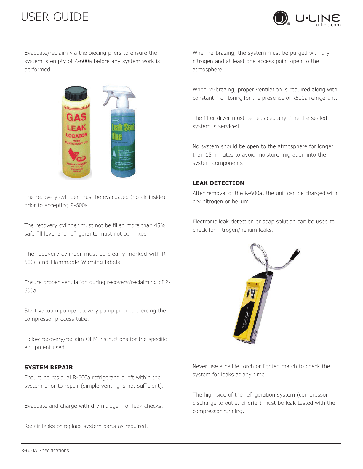
Evacuate/reclaim via the piecing pliers to ensure the
system is empty of R-600a before any system work is
performed.
The recovery cylinder must be evacuated (no air inside)
prior to accepting R-600a.
The recovery cylinder must not be filled more than 45%
safe fill level and refrigerants must not be mixed.
The recovery cylinder must be clearly marked with R-
600a and Flammable Warning labels.
Ensure proper ventilation during recovery/reclaiming of R-
600a.
Start vacuum pump/recovery pump prior to piercing the
compressor process tube.
Follow recovery/reclaim OEM instructions for the specific
equipment used.
SYSTEM REPAIR
Ensure no residual R-600a refrigerant is left within the
system prior to repair (simple venting is not sufficient).
Evacuate and charge with dry nitrogen for leak checks.
Repair leaks or replace system parts as required.
When re-brazing, the system must be purged with dry
nitrogen and at least one access point open to the
atmosphere.
When re-brazing, proper ventilation is required along with
constant monitoring for the presence of R600a refrigerant.
The filter dryer must be replaced any time the sealed
system is serviced.
No system should be open to the atmosphere for longer
than 15 minutes to avoid moisture migration into the
system components.
LEAK DETECTION
After removal of the R-600a, the unit can be charged with
dry nitrogen or helium.
Electronic leak detection or soap solution can be used to
check for nitrogen/helium leaks.
Never use a halide torch or lighted match to check the
system for leaks at any time.
The high side of the refrigeration system (compressor
discharge to outlet of drier) must be leak tested with the
compressor running.
38
R-600A Specications
USER GUIDE
u-line.com
The low side of the refrigeration system (evaporator,
compressor and suction line) must be leak tested with the
compressor off (equalized pressure).
RECHARGING
No air is ever to be allowed inside the refrigeration system
(R-600a refrigerant or dry nitrogen only).
Never use a torch on a fully charged refrigeration system.
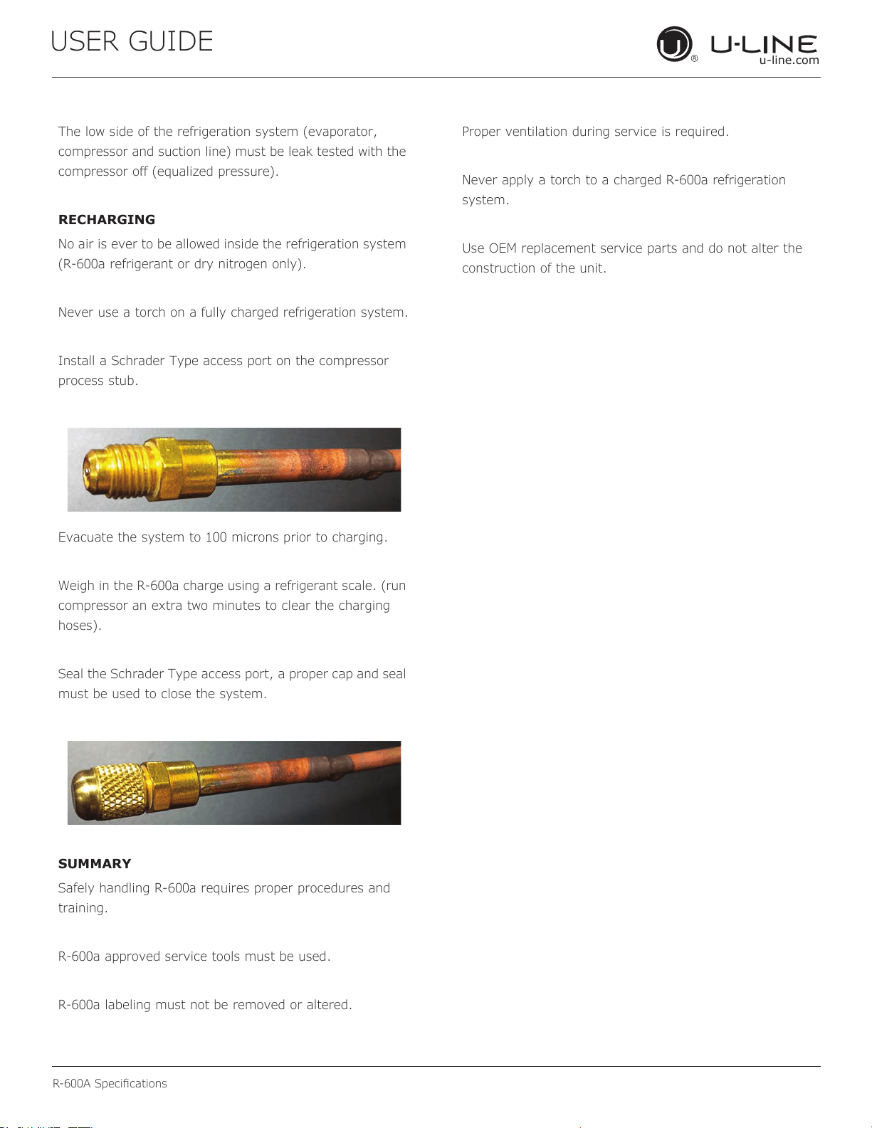
Install a Schrader Type access port on the compressor
process stub.
Evacuate the system to 100 microns prior to charging.
Weigh in the R-600a charge using a refrigerant scale. (run
compressor an extra two minutes to clear the charging
hoses).
Seal the Schrader Type access port, a proper cap and seal
must be used to close the system.
SUMMARY
Safely handling R-600a requires proper procedures and
training.
R-600a approved service tools must be used.
R-600a labeling must not be removed or altered.
Proper ventilation during service is required.
Never apply a torch to a charged R-600a refrigeration
system.
Use OEM replacement service parts and do not alter the
construction of the unit.
39
USER GUIDE
u-line.com
System Diagnosis Guide
System Diagnosis Guide
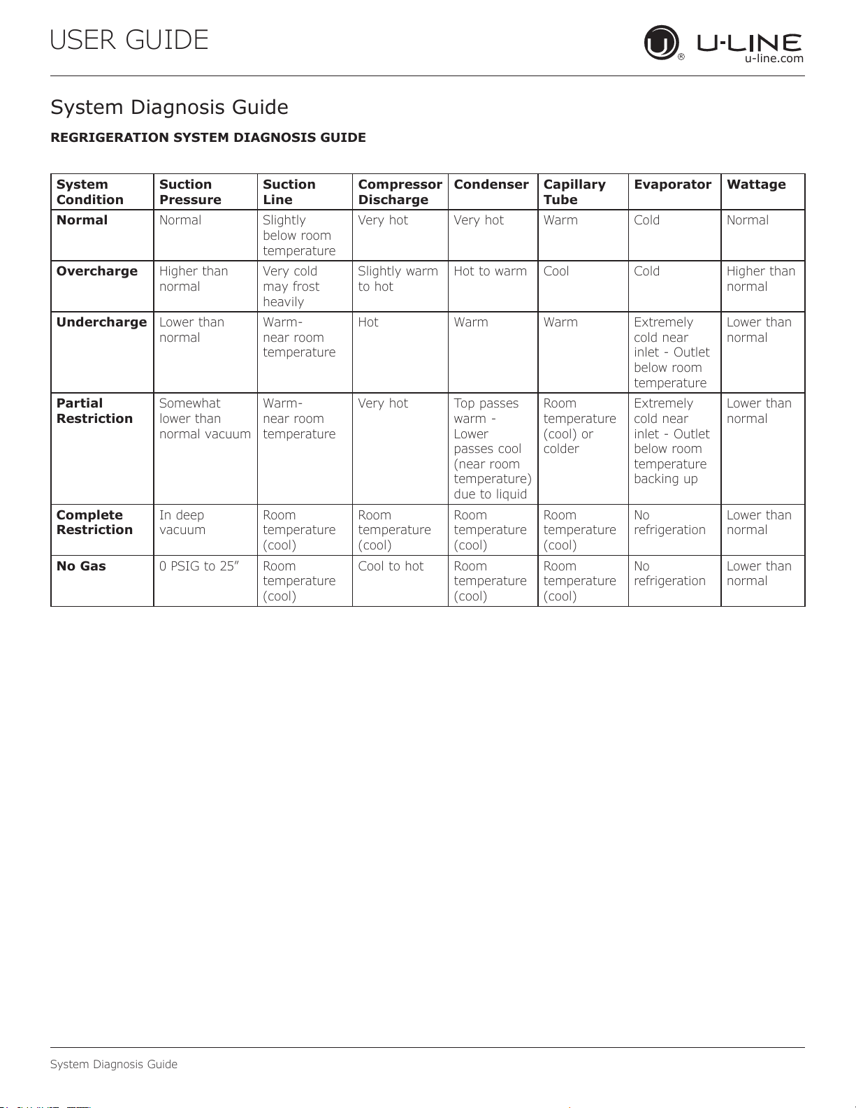
REGRIGERATION SYSTEM DIAGNOSIS GUIDE
System
Condition
Suction
Pressure
Suction
Line
Compressor
Discharge
Condenser Capillary
Tube
Evaporator Wattage
Normal Normal Slightly
below room
temperature
Very hot Very hot Warm Cold Normal
Overcharge Higher than
normal
Very cold
may frost
heavily
Slightly warm
to hot
Hot to warm Cool Cold Higher than
normal
Undercharge Lower than
normal
Warm-
near room
temperature
Hot Warm Warm Extremely
cold near
inlet - Outlet
below room
temperature
Lower than
normal
Partial
Restriction
Somewhat
lower than
normal vacuum
Warm-
near room
temperature
Very hot Top passes
warm -
Lower
passes cool
(near room
temperature)
due to liquid
Room
temperature
(cool) or
colder
Extremely
cold near
inlet - Outlet
below room
temperature
backing up
Lower than
normal
Complete
Restriction
In deep
vacuum
Room
temperature
(cool)
Room
temperature
(cool)
Room
temperature
(cool)
Room
temperature
(cool)
No
refrigeration
Lower than
normal
No Gas 0 PSIG to 25” Room
temperature
(cool)
Cool to hot Room
temperature
(cool)
Room
temperature
(cool)
No
refrigeration
Lower than
normal
40
USER GUIDE
u-line.com
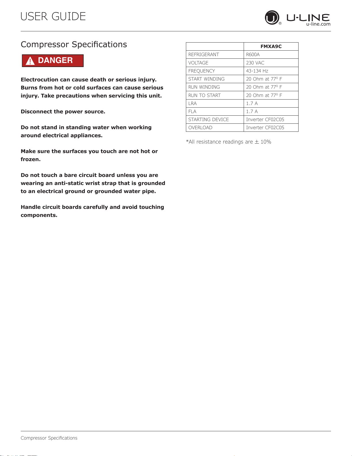
Compressor Specications
Electrocution can cause death or serious injury.
Burns from hot or cold surfaces can cause serious
injury. Take precautions when servicing this unit.
Disconnect the power source.
Do not stand in standing water when working
around electrical appliances.
Make sure the surfaces you touch are not hot or
frozen.
Do not touch a bare circuit board unless you are
wearing an anti-static wrist strap that is grounded
to an electrical ground or grounded water pipe.
Handle circuit boards carefully and avoid touching
components.
Compressor Specications
FMXA9C
REFRIGERANT R600A
VOLTAGE 230 VAC
FREQUENCY 43-134 Hz
START WINDING 20 Ohm at 77
o
F
RUN WINDING 20 Ohm at 77
o
F
RUN TO START 20 Ohm at 77
o
F
LRA 1.7 A
FLA 1.7 A
STARTING DEVICE Inverter CF02C05
OVERLOAD Inverter CF02C05
*All resistance readings are
+
10%
DANGER
!
41
USER GUIDE
u-line.com
Troubleshooting Extended
Troubleshooting - Extended
CAUTION
!
Never attempt to repair or perform maintenance
on the unit until the main electrical power has
been disconnected from the unit.
SPECIFIC ERRORS AND ISSUES
The advanced diagnostic capabilities of the electronic
controls utilized on the 1, 3, and 5 Class units allow for
easy and thorough troubleshooting.
Navigation of the control is the key and is explained in
the CONTROL OPERATION section of the manual, along
with control button layout, control function descriptions,
a service mode menu and service menu selection
explanations.
Verication of temperature and thermistor performance can
be identied by directly viewing thermistor readings in the
service mode.
Included in this section are some diagnostic tips and of
course, if additional help is required, please contact the
U-Line Corp, “Customer Care Facility” at +1.800.779.2547
for assistance.
NORMAL OPERATING SOUNDS
All models incorporate rigid foam insulated cabinets to
provide high thermal eciency and maximum sound
reduction for its internal working components. Despite
this technology, your model may make sounds that are
unfamiliar.
Normal operating sounds may be more noticeable because
of the unit’s environment. Hard surfaces such as cabinets,
wood, vinyl or tiled oors and paneled walls have a
tendency to reect normal appliance operating noises.
Listed below are common refrigeration components with a
brief description of the normal sounds they make. NOTE:
Your product may not contain all the components listed.
• Compressor: The compressor makes a hum or pulsing
sound that may be heard when it operates.
• Evaporator: Refrigerant owing through an evaporator
may sound like boiling liquid.
• Condenser Fan: Air moving through a condenser may
be heard.
• Automatic Defrost Drain Pan: Water may be heard
dripping or running into the drain pan when the unit is
in the defrost cycle.
Solenoid Valves: An occasional clicking sound may be
heard as solenoid valves are operated.
42
USER GUIDE
u-line.com
Troubleshooting Extended
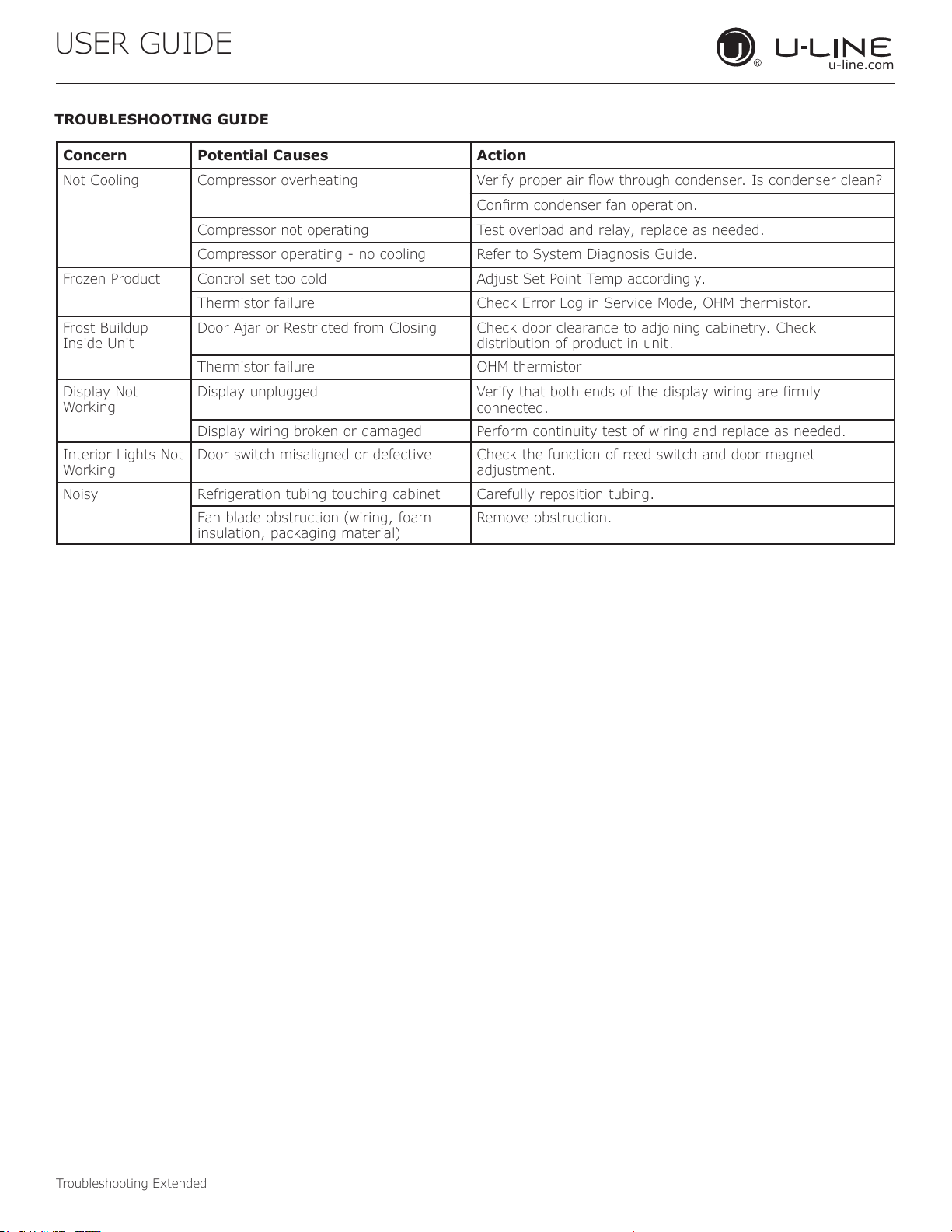
TROUBLESHOOTING GUIDE
Concern Potential Causes Action
Not Cooling Compressor overheating Verify proper air ow through condenser. Is condenser clean?
Conrm condenser fan operation.
Compressor not operating Test overload and relay, replace as needed.
Compressor operating - no cooling Refer to System Diagnosis Guide.
Frozen Product Control set too cold Adjust Set Point Temp accordingly.
Thermistor failure Check Error Log in Service Mode, OHM thermistor.
Frost Buildup
Inside Unit
Door Ajar or Restricted from Closing Check door clearance to adjoining cabinetry. Check
distribution of product in unit.
Thermistor failure OHM thermistor
Display Not
Working
Display unplugged Verify that both ends of the display wiring are rmly
connected.
Display wiring broken or damaged Perform continuity test of wiring and replace as needed.
Interior Lights Not
Working
Door switch misaligned or defective Check the function of reed switch and door magnet
adjustment.
Noisy Refrigeration tubing touching cabinet Carefully reposition tubing.
Fan blade obstruction (wiring, foam
insulation, packaging material)
Remove obstruction.
43
USER GUIDE
u-line.com
Troubleshooting Extended
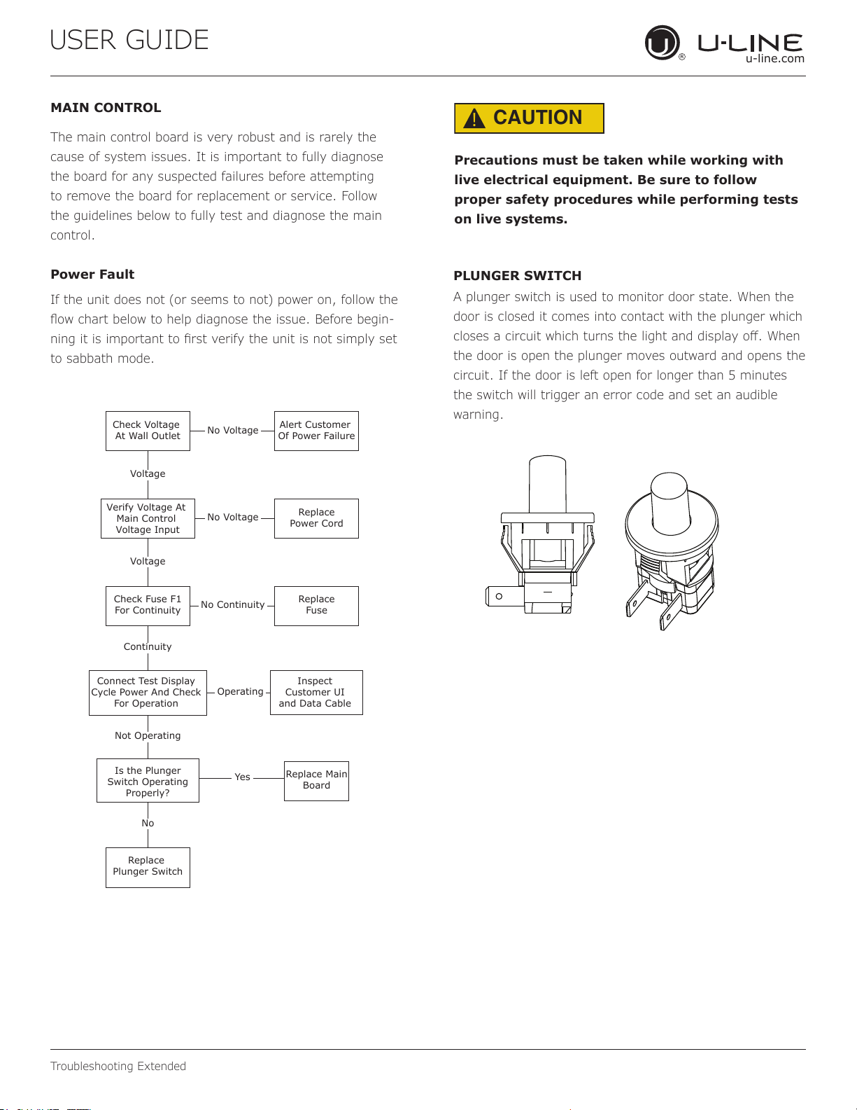
MAIN CONTROL
The main control board is very robust and is rarely the
cause of system issues. It is important to fully diagnose
the board for any suspected failures before attempting
to remove the board for replacement or service. Follow
the guidelines below to fully test and diagnose the main
control.
Power Fault
If the unit does not (or seems to not) power on, follow the
ow chart below to help diagnose the issue. Before begin-
ning it is important to rst verify the unit is not simply set
to sabbath mode.
Check Voltage
At Wall Outlet
Verify Voltage At
Main Control
Voltage Input
Check Fuse F1
For Continuity
Replace
Plunger Switch
Replace Main
Board
Replace
Fuse
Replace
Power Cord
Alert Customer
Of Power Failure
Is the Plunger
Switch Operating
Properly?
Inspect
Customer UI
and Data Cable
Connect Test Display
Cycle Power And Check
For Operation
No Voltage
No Voltage
Voltage
Continuity
Operating
Not Operating
No Continuity
No
Yes
Voltage
CAUTION
!
Precautions must be taken while working with
live electrical equipment. Be sure to follow
proper safety procedures while performing tests
on live systems.
PLUNGER SWITCH
A plunger switch is used to monitor door state. When the
door is closed it comes into contact with the plunger which
closes a circuit which turns the light and display o. When
the door is open the plunger moves outward and opens the
circuit. If the door is left open for longer than 5 minutes
the switch will trigger an error code and set an audible
warning.
44
USER GUIDE
u-line.com
Control Operation-Service
Control Operation-Service
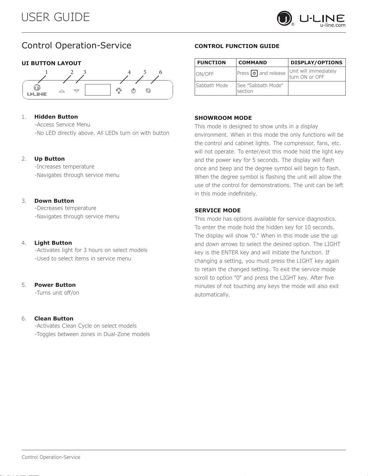
UI BUTTON LAYOUT
1. Hidden Button
2. Up Button
3. Down Button
4. Light Button
5. Power Button
6. Clean Button
-Access Service Menu
-No LED directly above. All LEDs turn on with button
-Increases temperature
-Navigates through service menu
-Decreases temperature
-Navigates through service menu
-Activates light for 3 hours on select models
-Used to select items in service menu
-Turns unit o/on
-Activates Clean Cycle on select models
-Toggles between zones in Dual-Zone models
CONTROL FUNCTION GUIDE
SHOWROOM MODE
This mode is designed to show units in a display
environment. When in this mode the only functions will be
the control and cabinet lights. The compressor, fans, etc.
will not operate. To enter/exit this mode hold the light key
and the power key for 5 seconds. The display will ash
once and beep and the degree symbol will begin to ash.
When the degree symbol is ashing the unit will allow the
use of the control for demonstrations. The unit can be left
in this mode indenitely.
SERVICE MODE
This mode has options available for service diagnostics.
To enter the mode hold the hidden key for 10 seconds.
The display will show “0.” When in this mode use the up
and down arrows to select the desired option. The LIGHT
key is the ENTER key and will initiate the function. If
changing a setting, you must press the LIGHT key again
to retain the changed setting. To exit the service mode
scroll to option “0” and press the LIGHT key. After ve
minutes of not touching any keys the mode will also exit
automatically.
1 2 3 4 5 6
FUNCTION COMMAND DISPLAY/OPTIONS
ON/OFF
Press
and release
Unit will immediately
turn ON or OFF
Sabbath Mode See “Sabbath Mode”
section
45
USER GUIDE
u-line.com
Control Operation-Service
SERVICE MODE GUIDE SERVICE MODE GUIDE
0. Exit
1. Thermistor 1 temperature not including osets.
2. Thermistor 2 temperature not including osets.
3. Thermistor 3 temperature not including osets.
4. Thermistor 4 temperature not including osets.
5. Thermistor 1 oset. (+/- 10)
6. Thermistor 2 oset. (+/- 10)
7. Thermistor 3 oset. (+/- 10)
8. Thermistor 4 oset. (+/- 10)
9. Thermistor 2 set point
10. Thermistor 3 set point.
11. Thermistor 4 set point.
12. Defrost Interval (0 to 99 hr)
13. Defrost duration (0 to 99 min)
14. Error Log (See Appx D)
15. Clear error log (hold light key until cleared)
16. Thermistor 1 dierential (+5)
17. Thermistor 3 dierential (+5)
18. Evaporator fan on delay (0 to 99 sec)
19. Evaporator fan o delay (0 to 99 sec)
20. Individual component toggle
- Option #0 – Exit
- Option #1 – Relay 1
- Option #2 – Relay 2
- Option #3 – Relay 3
- Option #4 – Relay 4
- Option #5 – Relay 5
- Option #6 – Relay 6
- Option #7 – DC Output 1
- Option #8 – DC Output 2
- Option #9 – DC Output 3
- Option #10 – DC Output 4
- Option #11 – DC Output 5
- Option #12 – Serial output (Compressor)
21. Model number
22. Light All Segments
23. Activate Defrost/Harvest- press and hold for 3 seconds
to activate defrost/harvest
24. Defaults- press and hold for 3 seconds to restore all
values to factory defaults.
25. Main Software (Display only)
26. Live Log Period (frequency that data is output to
diagnostics port)
27. Factory test mode (0=O, 1=On)
28. Compressor RPM
29. Freeze time adjust (Model 54 only)
30. Harvest time adjust (Model 54 only)
31. Low temp alarm limit (Model 55 only)
32. High temp alarm limit (Model 55 only)
1. THERMISTOR 1 — ZONE
This shows the pure thermistor reading with no osets
taken into account.
2. THERMISTOR 2 — EVAPORATOR
This shows the pure thermistor reading with no osets
taken into account.
3. Does not apply to this model.
4. Does not apply to this model.
5. THERMISTOR 1 — ZONE OFFSET
(DO NOT MAKE AN ADJUSTMENT TO THIS WITHOUT
CONTACTING TECH LINE: 800-779-2547)
This calibration is only to be used if actual
temperature at thermistor #1 is o from set point.
By adjusting the oset higher we can force the unit
to drive the temperature down below the set point.
(example: adjusting from 0 to +2 will drop the unit
temperature 2 degrees)
6. THERMISTOR 2 — EVAPORATOR OFFSET
(DO NOT MAKE AN ADJUSTMENT TO THIS WITHOUT
CONTACTING TECH LINE: 800-779-2547)
7. Does not apply to this model.
8. Does not apply to this model.
9. THERMISTOR 2 — SET POINT MINUS OFFSET
This shows the thermistor reading with osets taken
into account.
10. Does not apply to this model.
11. Does not apply to this model.
12. ADJUST DEFROST INTERVAL — 3 TO 24
HOURS
This will adjust the interval between defrosts from
3 to 24 hours. Adjusting from the factory settings
may cause undesired temperature in the refrigerator
section.
13. ADJUST DEFROST DURATION — 0 TO 99
MINUTES
The length of the defrost can be adjusted 0 to 99
minutes long. The other defrost parameters still apply.
Lengthening a defrost may cause higher than normal
temperatures in the refrigerator section.
14. VIEW ERROR LOG
A list of errors in the order they occurred will scroll
on the display. All errors are logged in memory. Only
door error is displayed on the display and has an
audible signal.
E0: Door 1 (upper) open.
E1: Thermistor 1 open.
E2: Thermistor 2 open.
46
USER GUIDE
u-line.com
Control Operation-Service
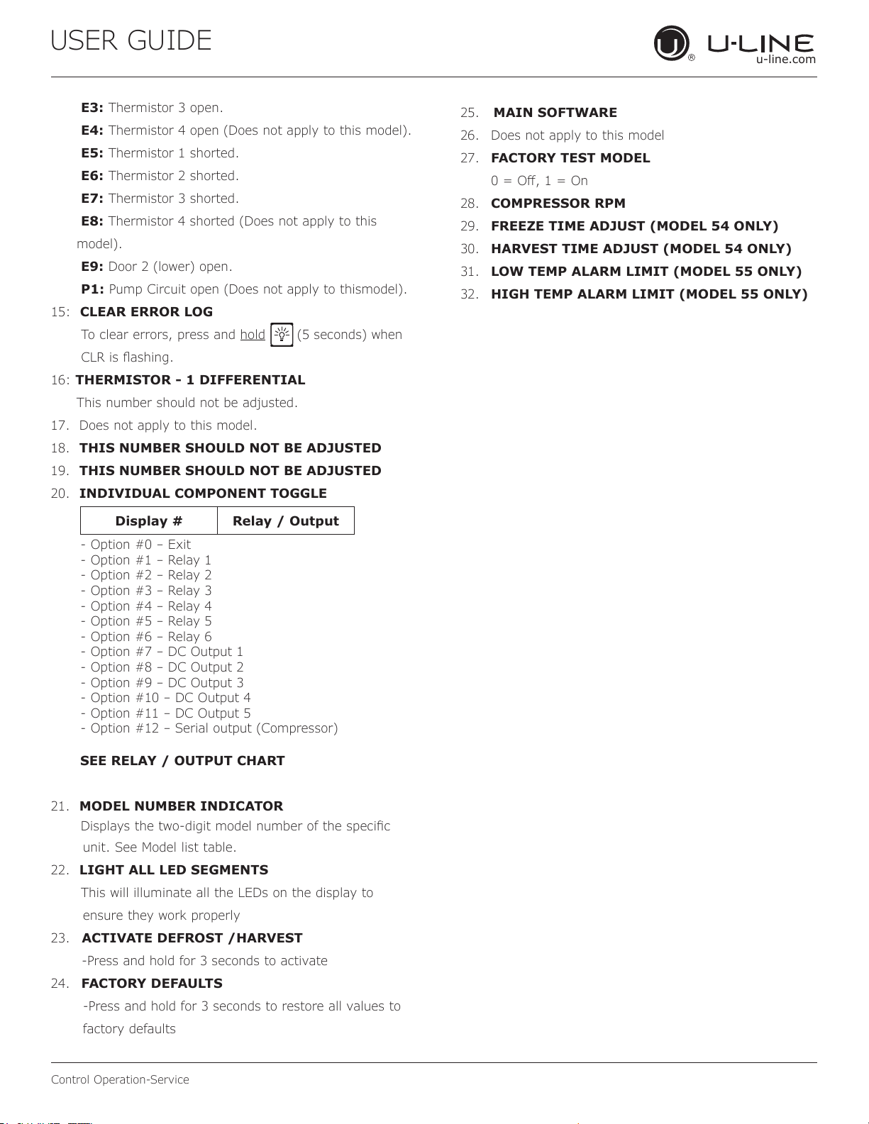
E3: Thermistor 3 open.
E4: Thermistor 4 open (Does not apply to this model).
E5: Thermistor 1 shorted.
E6: Thermistor 2 shorted.
E7: Thermistor 3 shorted.
E8: Thermistor 4 shorted (Does not apply to this
model).
E9: Door 2 (lower) open.
P1: Pump Circuit open (Does not apply to thismodel).
15: CLEAR ERROR LOG
To clear errors, press and hold (5 seconds) when
CLR is ashing.
16: THERMISTOR - 1 DIFFERENTIAL
This number should not be adjusted.
17. Does not apply to this model.
18. THIS NUMBER SHOULD NOT BE ADJUSTED
19. THIS NUMBER SHOULD NOT BE ADJUSTED
20. INDIVIDUAL COMPONENT TOGGLE
21. MODEL NUMBER INDICATOR
Displays the two-digit model number of the specic
unit. See Model list table.
22. LIGHT ALL LED SEGMENTS
This will illuminate all the LEDs on the display to
ensure they work properly
23. ACTIVATE DEFROST /HARVEST
-Press and hold for 3 seconds to activate
24. FACTORY DEFAULTS
-Press and hold for 3 seconds to restore all values to
factory defaults
25. MAIN SOFTWARE
26. Does not apply to this model
27. FACTORY TEST MODEL
0 = O, 1 = On
28. COMPRESSOR RPM
29. FREEZE TIME ADJUST (MODEL 54 ONLY)
30. HARVEST TIME ADJUST (MODEL 54 ONLY)
31. LOW TEMP ALARM LIMIT (MODEL 55 ONLY)
32. HIGH TEMP ALARM LIMIT (MODEL 55 ONLY)
Display # Relay / Output
- Option #0 – Exit
- Option #1 – Relay 1
- Option #2 – Relay 2
- Option #3 – Relay 3
- Option #4 – Relay 4
- Option #5 – Relay 5
- Option #6 – Relay 6
- Option #7 – DC Output 1
- Option #8 – DC Output 2
- Option #9 – DC Output 3
- Option #10 – DC Output 4
- Option #11 – DC Output 5
- Option #12 – Serial output (Compressor)
SEE RELAY / OUTPUT CHART
47
USER GUIDE
u-line.com
Control Operation-Service
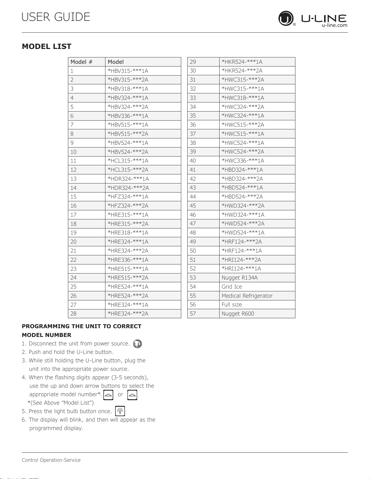
MODEL LIST
Model # Model
1 *HBV315-***1A
2 *HBV315-***2A
3 *HBV318-***1A
4 *HBV324-***1A
5 *HBV324-***2A
6 *HBV336-***1A
7 *HBV515-***1A
8 *HBV515-***2A
9 *HBV524-***1A
10 *HBV524-***2A
11 *HCL315-***1A
12 *HCL315-***2A
13 *HDR324-***1A
14 *HDR324-***2A
15 *HFZ324-***1A
16 *HFZ324-***2A
17 *HRE315-***1A
18 *HRE315-***2A
19 *HRE318-***1A
20 *HRE324-***1A
21 *HRE324-***2A
22 *HRE336-***1A
23 *HRE515-***1A
24 *HRE515-***2A
25 *HRE524-***1A
26 *HRE524-***2A
27 *HRE324-***1A
28 *HRE324-***2A
29 *HKR524-***1A
30 *HKR524-***2A
31 *HWC315-***2A
32 *HWC315-***1A
33 *HWC318-***1A
34 *HWC324-***2A
35 *HWC324-***1A
36 *HWC515-***2A
37 *HWC515-***1A
38 *HWC524-***1A
39 *HWC524-***2A
40 *HWC336-***1A
41 *HBD324-***1A
42 *HBD324-***2A
43 *HBD524-***1A
44 *HBD524-***2A
45 *HWD324-***2A
46 *HWD324-***1A
47 *HWD524-***2A
48 *HWD524-***1A
49 *HRF124-***2A
50 *HRF124-***1A
51 *HRI124-***2A
52 *HRI124-***1A
53 Nugget R134A
54 Grid Ice
55 Medical Refrigerator
56 Full size
57 Nugget R600
PROGRAMMING THE UNIT TO CORRECT
MODEL NUMBER
1. Disconnect the unit from power source.
2. Push and hold the U-Line button.
3. While still holding the U-Line button, plug the
unit into the appropriate power source.
4. When the ashing digits appear (3-5 seconds),
use the up and down arrow buttons to select the
appropriate model number*. or
*(See Above “Model List”)
5. Press the light bulb button once.
6. The display will blink, and then will appear as the
programmed display.
48
USER GUIDE
u-line.com
Control Operation-Service
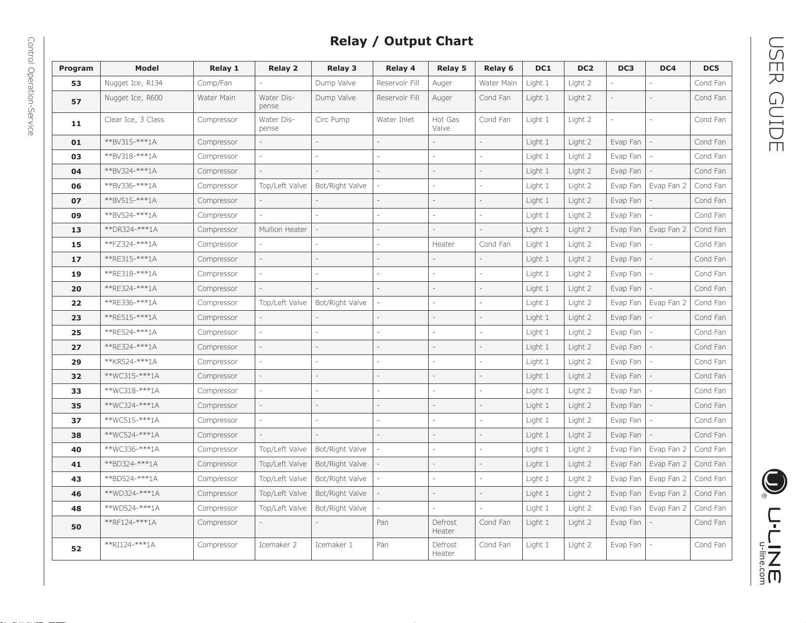
Program Model Relay 1 Relay 2 Relay 3 Relay 4 Relay 5 Relay 6 DC1 DC2 DC3 DC4 DC5
53
Nugget Ice, R134 Comp/Fan - Dump Valve Reservoir Fill Auger Water Main Light 1 Light 2 - - Cond Fan
57
Nugget Ice, R600 Water Main Water Dis-
pense
Dump Valve Reservoir Fill Auger Cond Fan Light 1 Light 2 - - Cond Fan
11
Clear Ice, 3 Class Compressor Water Dis-
pense
Circ Pump Water Inlet Hot Gas
Valve
Cond Fan Light 1 Light 2 - - Cond Fan
01
**BV315-***1A Compressor - - - - - Light 1 Light 2 Evap Fan - Cond Fan
03
**BV318-***1A Compressor - - - - - Light 1 Light 2 Evap Fan - Cond Fan
04
**BV324-***1A Compressor - - - - - Light 1 Light 2 Evap Fan - Cond Fan
06
**BV336-***1A Compressor Top/Left Valve Bot/Right Valve - - - Light 1 Light 2 Evap Fan Evap Fan 2 Cond Fan
07
**BV515-***1A Compressor - - - - - Light 1 Light 2 Evap Fan - Cond Fan
09
**BV524-***1A Compressor - - - - - Light 1 Light 2 Evap Fan - Cond Fan
13
**DR324-***1A Compressor Mullion Heater - - - - Light 1 Light 2 Evap Fan Evap Fan 2 Cond Fan
15
**FZ324-***1A Compressor - - - Heater Cond Fan Light 1 Light 2 Evap Fan - Cond Fan
17
**RE315-***1A Compressor - - - - - Light 1 Light 2 Evap Fan - Cond Fan
19
**RE318-***1A Compressor - - - - - Light 1 Light 2 Evap Fan - Cond Fan
20
**RE324-***1A Compressor - - - - - Light 1 Light 2 Evap Fan - Cond Fan
22
**RE336-***1A Compressor Top/Left Valve Bot/Right Valve - - - Light 1 Light 2 Evap Fan Evap Fan 2 Cond Fan
23
**RE515-***1A Compressor - - - - - Light 1 Light 2 Evap Fan - Cond Fan
25
**RE524-***1A Compressor - - - - - Light 1 Light 2 Evap Fan - Cond Fan
27
**RE324-***1A Compressor - - - - - Light 1 Light 2 Evap Fan - Cond Fan
29
**KR524-***1A Compressor - - - - - Light 1 Light 2 Evap Fan - Cond Fan
32
**WC315-***1A Compressor - - - - - Light 1 Light 2 Evap Fan - Cond Fan
33
**WC318-***1A Compressor - - - - - Light 1 Light 2 Evap Fan - Cond Fan
35
**WC324-***1A Compressor - - - - - Light 1 Light 2 Evap Fan - Cond Fan
37
**WC515-***1A Compressor - - - - - Light 1 Light 2 Evap Fan - Cond Fan
38
**WC524-***1A Compressor - - - - - Light 1 Light 2 Evap Fan - Cond Fan
40
**WC336-***1A Compressor Top/Left Valve Bot/Right Valve - - - Light 1 Light 2 Evap Fan Evap Fan 2 Cond Fan
41
**BD324-***1A Compressor Top/Left Valve Bot/Right Valve - - - Light 1 Light 2 Evap Fan Evap Fan 2 Cond Fan
43
**BD524-***1A Compressor Top/Left Valve Bot/Right Valve - - - Light 1 Light 2 Evap Fan Evap Fan 2 Cond Fan
46
**WD324-***1A Compressor Top/Left Valve Bot/Right Valve - - - Light 1 Light 2 Evap Fan Evap Fan 2 Cond Fan
48
**WD524-***1A Compressor Top/Left Valve Bot/Right Valve - - - Light 1 Light 2 Evap Fan Evap Fan 2 Cond Fan
50
**RF124-***1A Compressor - - Pan Defrost
Heater
Cond Fan Light 1 Light 2 Evap Fan - Cond Fan
52
**RI124-***1A Compressor Icemaker 2 Icemaker 1 Pan Defrost
Heater
Cond Fan Light 1 Light 2 Evap Fan - Cond Fan
Relay / Output Chart
49
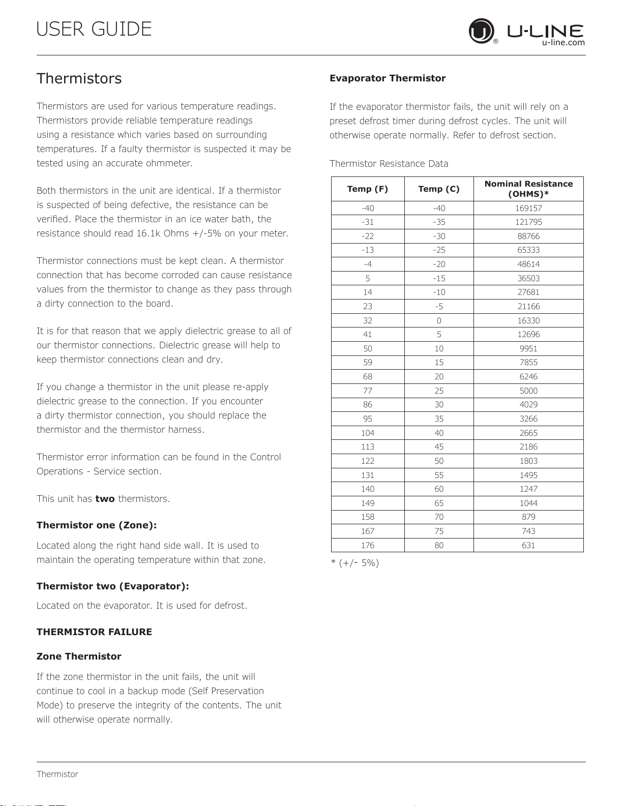
USER GUIDE
u-line.com
Thermistor
Evaporator Thermistor
If the evaporator thermistor fails, the unit will rely on a
preset defrost timer during defrost cycles. The unit will
otherwise operate normally. Refer to defrost section.
Thermistor Resistance Data
Thermistors
Thermistors are used for various temperature readings.
Thermistors provide reliable temperature readings
using a resistance which varies based on surrounding
temperatures. If a faulty thermistor is suspected it may be
tested using an accurate ohmmeter.
Both thermistors in the unit are identical. If a thermistor
is suspected of being defective, the resistance can be
veried. Place the thermistor in an ice water bath, the
resistance should read 16.1k Ohms +/-5% on your meter.
Thermistor connections must be kept clean. A thermistor
connection that has become corroded can cause resistance
values from the thermistor to change as they pass through
a dirty connection to the board.
It is for that reason that we apply dielectric grease to all of
our thermistor connections. Dielectric grease will help to
keep thermistor connections clean and dry.
If you change a thermistor in the unit please re-apply
dielectric grease to the connection. If you encounter
a dirty thermistor connection, you should replace the
thermistor and the thermistor harness.
Thermistor error information can be found in the Control
Operations - Service section.
This unit has two thermistors.
Thermistor one (Zone):
Located along the right hand side wall. It is used to
maintain the operating temperature within that zone.
Thermistor two (Evaporator):
Located on the evaporator. It is used for defrost.
THERMISTOR FAILURE
Zone Thermistor
If the zone thermistor in the unit fails, the unit will
continue to cool in a backup mode (Self Preservation
Mode) to preserve the integrity of the contents. The unit
will otherwise operate normally.
* (+/
- 5%)
Temp (F) Temp (C)
Nominal Resistance
(OHMS)*
-40 -40 169157
-31 -35 121795
-22 -30 88766
-13 -25 65333
-4 -20 48614
5 -15 36503
14 -10 27681
23 -5
21166
32 0 16330
41 5 12696
50 10 9951
59 15 7855
68 20 6246
77 25 5000
86 30 4029
95 35 3266
104 40 2665
113 45 2186
122 50 1803
131 55 1495
140 60 1247
149 65 1044
158 70 879
167 75 743
176 80 631
50
USER GUIDE
u-line.com
Defrost
Defrost
This unit defrosts every 12 hours of compressor runtime for 45 minutes. If you have veried that the unit does
not have an ambient air leak, utilize the Control Operation - Service section and adjust unit to defrost every 9
hours for 60 minutes. Also, adjust the #2 thermistor to -4 instead of 0.
51
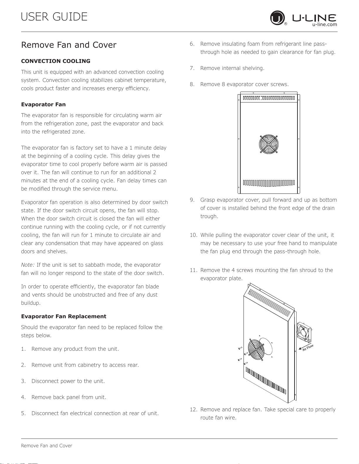
USER GUIDE
u-line.com
Remove Fan and Cover
Remove Fan and Cover
CONVECTION COOLING
This unit is equipped with an advanced convection cooling
system. Convection cooling stabilizes cabinet temperature,
cools product faster and increases energy eciency.
Evaporator Fan
The evaporator fan is responsible for circulating warm air
from the refrigeration zone, past the evaporator and back
into the refrigerated zone.
The evaporator fan is factory set to have a 1 minute delay
at the beginning of a cooling cycle. This delay gives the
evaporator time to cool properly before warm air is passed
over it. The fan will continue to run for an additional 2
minutes at the end of a cooling cycle. Fan delay times can
be modied through the service menu.
Evaporator fan operation is also determined by door switch
state. If the door switch circuit opens, the fan will stop.
When the door switch circuit is closed the fan will either
continue running with the cooling cycle, or if not currently
cooling, the fan will run for 1 minute to circulate air and
clear any condensation that may have appeared on glass
doors and shelves.
Note: If the unit is set to sabbath mode, the evaporator
fan will no longer respond to the state of the door switch.
In order to operate eciently, the evaporator fan blade
and vents should be unobstructed and free of any dust
buildup.
Evaporator Fan Replacement
Should the evaporator fan need to be replaced follow the
steps below.
1. Remove any product from the unit.
2. Remove unit from cabinetry to access rear.
3. Disconnect power to the unit.
4. Remove back panel from unit.
5. Disconnect fan electrical connection at rear of unit.
6. Remove insulating foam from refrigerant line pass-
through hole as needed to gain clearance for fan plug.
7. Remove internal shelving.
8. Remove 8 evaporator cover screws.
9. Grasp evaporator cover, pull forward and up as bottom
of cover is installed behind the front edge of the drain
trough.
10. While pulling the evaporator cover clear of the unit, it
may be necessary to use your free hand to manipulate
the fan plug end through the pass-through hole.
11. Remove the 4 screws mounting the fan shroud to the
evaporator plate.
12. Remove and replace fan. Take special care to properly
route fan wire.
Air Flow
52
USER GUIDE
u-line.com
Remove Fan and Cover
NOTICE
Fan must be oriented to pull air in through lower
evaporator cover vents and push air out at fan
mounting location.
13. Installation is the reverse of removal.
14. Care must be taken to assure the bottom of the
evaporator cover is reinstalled behind the front edge of
the train trough.
15. Use sealant gum to seal any openings at rear of unit
before replacing rear cover.
16. Reinstall unit taking care to level, space and secure as
found.
53
Copyright © 2020 U-Line Corporation. All Rights Reserved. | Publication Number 30379 | 11/2020 Rev. O
U-Line Corporation (U-Line) Limited Warranty
One Year Limited Warranty
For one year from the date of original purchase, this warranty covers all parts and labor to repair or replace any part of the product that
proves to be defective in materials or workmanship. For products installed and used for normal residential use, material cosmetic defects
are included in this warranty, with coverage limited to 60 days from the date of original purchase. All service provided by U-Line under the
above warranty must be performed by a U-Line factory authorized servicer, unless otherwise specified by U-Line. Service provided during
normal business hours.
Two Year Limited Warranty (5 Class Product)
For two years from the date of original purchase, this warranty covers all parts and labor to repair or replace any part of the product that
proves to be defective in materials or workmanship. For products installed and used for normal residential use, material cosmetic defects
are included in this warranty, with coverage limited to 60 days from the date of original purchase. All service provided by U-Line under the
above warranty must be performed by a U-Line factory authorized servicer, unless otherwise specified by U-Line. Service provided during
normal business hours.
Available Second & Third Year Limited Warranty
In addition to the standard one and two year warranties outlined above, U-Line offers a one year extension of the warranties from the date
of purchase, free of charge. To take advantage of this extension, you must register your product with U-Line within 60 days from the date
of purchase at u-line.com and provide proof of purchase.
Five Year Sealed System Limited Warranty
For five years from the date of original purchase, U-Line will repair or replace the following parts, labor not included, that prove to be
defective in materials or workmanship: compressor, condenser, evaporator, drier, and all connecting tubing. All service provided by U-Line
under the above warranty must be performed by a U-Line factory authorized servicer, unless otherwise specified by U-Line. Service
provided during normal business hours.
Terms
These warranties apply only to products installed in any one of the fifty states of the United States, the District of Columbia, or the ten
provinces of Canada. The warranties do not cover any parts or labor to correct any defect caused by negligence, accident or improper use,
maintenance, installation, service, repair, acts of God, fire, flood or other natural disasters. The product must be installed, operated, and
maintained in accordance with your product’s User Guide.
The remedies described above for each warranty are the only ones that U-Line will provide, either under these warranties or under any
warranty arising by operation of law. U-Line will not be responsible for any consequential or incidental damages arising from the breach of
these warranties or any other warranty, whether express, implied, or statutory. Some states do not allow the exclusion or limitation of
incidental or consequential damages, so the above limitation or exclusion may not apply to you. These warranties give you specific legal
rights, and you may also have other rights which vary from state to state.
Any warranty that may be implied in connection with your purchase or use of the product, including any warranty of merchantability or any
warranty fit for a particular purpose is limited to the duration of these warranties, and only extends to five years in duration for the parts
described in the section related to the five year limited warranty above. Some states do not allow limitations on how long an implied warranty
lasts, so the above limitations may not apply to you.
• The warranties only apply to the original purchaser and are non-transferable.
• The second, third, and five year warranties cover products installed and used for normal residential or designated marine use only.
• The warranties apply to units operated outside only if designed for outdoor use by model and serial number.
• U-Line Commercial products are covered by the one year and 5 year limited warranties and are not eligible for the second and
third year limited warranties.
• Replacement water filters, light bulbs, and other consumable parts are not covered by these warranties.
• The start of U-Line’s obligation is limited to four years after the shipment date from U-Line.
• In-home instruction on how to use your product is not covered by these warranties.
• Food, beverage, and medicine loss are not covered by these warranties.
• If the product is located in an area where U-Line factory authorized service is not available, you may be responsible for a trip
charge or you may be required to bring the product to a U-Line factory authorized service location at your own cost and expense.
• Units purchased after use as floor displays, and/or certified reconditioned units, are covered by the limited one year warranty only
and no coverage is provided for cosmetic defects.
• Signal issues related to Wi-Fi connectivity are not covered by these warranties.
For parts and service assistance, or to find U-Line factory authorized service near you, contact U-Line:
8900 N. 55
th
Street, Milwaukee, WI 53223 • u-line.com • onlineservice@u-line.com • +1.414.354.0300
54