Loading ...
Loading ...
Loading ...
— 19 —
Assembly
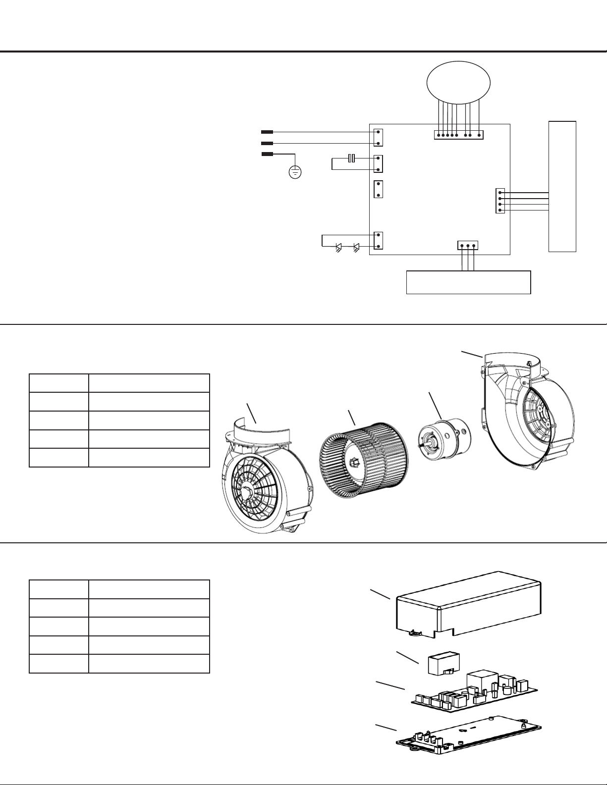
Circuit Diagram
Blower Assembly
Electrical Assembly
Number Part
1 Left blower housing
2 Impeller
3 Motor
4 Right blower housing
Number Part
1 Junctionboxcover
2 Capacitor
3 Main PCB board
4 Junctionboxbottom
u
v
w
u
v
w
x
x
AC 0V 60Hz12
Controls PCB
Main PCB
L
N
E
Capacitor
MAX 10.2V 250mA 2.5W
Temperature / Humidity
Sensor
CN6
CN5
(Optional)
CN1
CN2
CN4
Motor
CN3
CH B
CN8
+
_
LED Pucks
___
Loading ...
Loading ...
Loading ...