
230111-20
GAS RANGES ELECTRIC
STATIC / CONVECTION
OVENS
GE505 GE54
GE506 GE56
GE508 GE58
I N S T A L L A T I O N A N D O P E R A T I O N M A N U A L
The reproduction or copying of any part of this manual by any means whatsoever is strictly forbidden unless authorized previously in
writing by the manufacturer.
In line with policy to continually develop and improve its products, Moffat Ltd. reserves the right to change the specifications and
design without prior notice.
© Copyright Moffat Ltd. August 2017.
Moffat Limited
Rolleston 7675
New Zealand
AUSTRALIA
Moffat Pty Limited
Web: www.moffat.com.au
E.Mail: [email protected]m.au
Main Office: (tel) +61 (03) 9518 3888
(fax) +61 (03) 9518 3838
Service: (tel): 1800 622 216
Spares: (tel): 1800 337 963
Customer Service: (tel): 1800 335 315
(fax): 1800 350 281
CANADA
Serve Canada
Web: www.servecanada.com
E.Mail: [email protected]m
Sales: (tel): 800 551 8795 (Toll Free)
Service: (tel): 800 263 1455 (Toll Free)
NEW ZEALAND
Moffat Limited
Web: www.moffat.co.nz
E.Mail: [email protected].nz
Main Office: (tel): 0800 663328
UNITED KINGDOM
Blue Seal
Web: www.blue-seal.co.uk
E.Mail: sales@blue-seal.co.uk
Sales: (tel): +44 121 327 5575
(fax): +44 121 327 9711
Spares: (tel): +44 121 322 6640
(fax): +44 121 327 9201
Service: (tel): +44 121 322 6644
(fax): +44 121 327 6257
UNITED STATES
Moffat
Web: www.moffat.com
Sales: (tel): 1-800 551 8795 (Toll Free)
(tel): 336 661 1556
(fax): 336 661 9546
Service: (tel): 866 673 7937 (Toll Free)
REST OF WORLD
Moffat Limited
Web: www.moffat.co.nz
E.Mail: export@moffat.co.nz
1
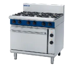
Blue Seal Gas Range Electric Static/Convection Ovens
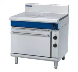
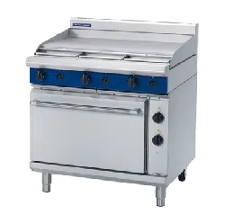
GE505 Gas Range Electric Static Oven -750mm wide.
GE506 Gas Range Electric Static Oven - 900mm wide.
GE508 Gas Range Electric Static Oven - 1200mm wide.
GE54 Gas Range Electric Convection Oven - 750mm wide.
GE56 Gas Range Electric Convection Oven - 900mm wide.
GE58 Gas Range Electric Convection Oven - 1200mm wide.
Model Numbers Covered in this Specification
General
Gas Supply Requirements
Gas Connection
Electrical Supply Requirements
Electrical Connection
Installation Requirements
Unpacking
Location
Clearances
Assembly
Gas Connection
Electrical Connection
Commissioning
Operation Guide
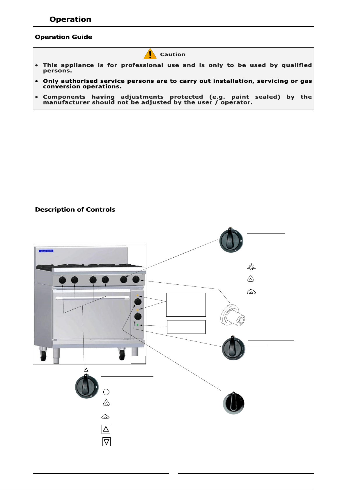
Description of Controls
Open Burners
Griddle
Oven
Before Commencing Cleaning
Open Burner Cleaning
Griddle Plate Cleaning
Oven Interior Cleaning
Stainless Steel Surfaces
Conversion Procedure
Gas Specifications
2
We are confident that you will be delighted with your BLUE SEAL GAS RANGE ELECTRICAL STATIC /
CONVECTION OVEN and it will become a most valued appliance in your commercial kitchen.
To ensure you receive the utmost benefit from your new Blue Seal appliance, there are two important
things you can do.
Please read the instruction book carefully and follow directions given. The time taken will be well spent.
If you are unsure of any aspect of the installation, instructions or performance of your appliance,
contact your BLUE SEAL dealer promptly. In many cases a phone call could answer your question.
These instructions are only valid if the country code appears on the appliance. If the code does not
appear on the appliance, refer to the supplier of this appliance to obtain the technical instructions for
adapting the appliance to the conditions for use in that country.
GREAT CARE MUST BE TAKEN BY THE OPERATOR TO USE THE EQUIPMENT SAFELY TO GUARD IT AGAINST RISK OF
FIRE.
THE APPLIANCE MUST NOT BE LEFT ON UNATTENDED.
IT IS RECOMMENDED THAT A REGULAR INSPECTION IS MADE BY A COMPETENT SERVICE PERSON TO
ENSURE CORRECT AND SAFE OPERATION OF YOUR APPLIANCE IS MAINTAINED.
DO NOT STORE OR USE GASOLINE OR OTHER FLAMMABLE VAPOURS OR LIQUIDS IN THE VICINITY OF
THIS OR ANY OTHER APPLIANCE.
DO NOT SPRAY AEROSOLS IN THE VICINITY OF THIS APPLIANCE WHILE IT IS IN OPERATION.
IMPROPER INSTALLATION, ADJUSTMENT, ALTERATION, SERVICE OR MAINTENANCE CAN CAUSE PROPERTY
DAMAGE, INJURY OR DEATH. READ THE INSTALLATION, OPERATING AND MAINTENANCE INSTRUCTIONS
THOROUGHLY BEFORE INSTALLING OR SERVICING THIS APPLIANCE.
INSTRUCTIONS TO BE FOLLOWED IN THE EVENT THE USER SMELLS GAS ARE TO BE POSTED IN A PROMINENT
LOCATION. THIS INFORMATION SHALL BE OBTAINED BY CONSULTING THE LOCAL GAS SUPPLIER.
3
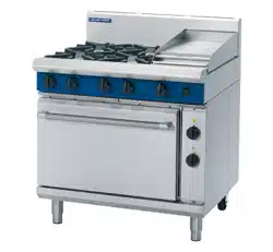
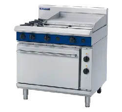
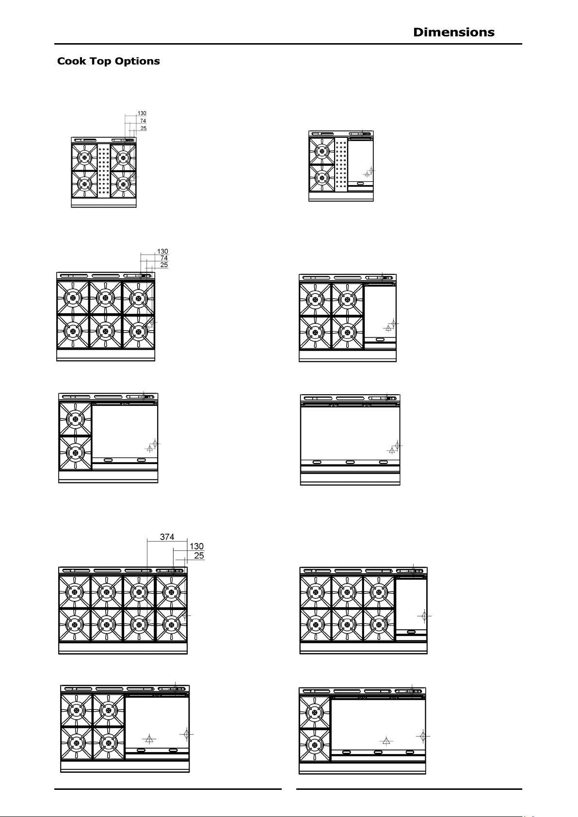
GE505D[1] 4 Open Burners + Electric Static Oven.
GE505C[1] 2 Open Burners + 300 mm Griddle + Electric Static Oven.
GE506D[1] 6 Open Burners + Electric Static Oven.
GE506C[1] 4 Open Burners + 300 mm Griddle + Electric Static Oven.
GE506B[1] 2 Open Burners + 600 mm Griddle + Electric Static Oven.
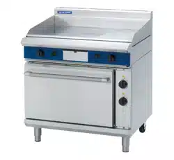
GE506A[1] 900 mm Griddle + Electric Static Oven.
GE508D[1] 8 Open Burners + Electric Static Oven.
GE508C[1] 6 Open Burners + 300 mm Griddle + Electric Static Oven.
GE508B[1] 4 Open Burners + 600 mm Griddle + Electric Static Oven.
GE508A[1] 2 Open Burners + 900 mm Griddle + Electric Static Oven.
GE54D[1] 4 Open Burners + Electric Convection Oven.
GE54C[1] 2 Open Burners + 300 mm Griddle + Electric Convection Oven.
GE56D[1] 6 Open Burners + Electric Convection Oven.
GE56C[1] 4 Open Burners + 300 mm Griddle + Electric Convection Oven.
GE56B[1] 2 Open Burners + 600 mm Griddle + Electric Convection Oven.
GE56A[1] 900 mm Griddle + Electric Convection Oven.
GE58D[1] 8 Open Burners + Electric Convection Oven.
GE58C[1] 6 Open Burners + 300 mm Griddle + Electric Convection Oven.
GE58B[1] 4 Open Burners + 600 mm Griddle + Electric Convection Oven.
GE58A[1] 2 Open Burners + 900 mm Griddle + Electric Convection Oven.
[1] - Open Burner Options;
F - With Flame Failure Protection.
PF - With Pilot and Flame Failure Protection.
A heavy duty, general purpose Gas Range with Electric Static / Convection Oven created for compact
modular kitchens. It has a high option Cook Top / Griddle arrangement and is available on industrial
adjustable feet or on robust rollers.
Open Burners are available in either 'PF' (Pilot and Flame Failure) or 'F' (Flame Failure Only) options.
Open Burner and Griddle options are fitted with individual flame failure for each open burner.
Griddles are fitted with pilot, flame failure and piezo ignition as standard. Easy clean stainless steel
external finish.
Easy clean stainless external finish.
4
- Australia
- New Zealand
- United Kingdom
Category: II
2H3P
(20, 37).
Flue Type: A
1.
* - Measure burner operating pressure at manifold test point with two burners operating at full
setting. Operating pressure is ex-factory set, through appliance regulator and is not to be
adjusted, apart from when converting between gases, if required. (Refer to ‘Gas Conversion’
section for details).
Input Rate (N.H.G.C.)
- each Open Burner
28 MJ/hr
28 MJ/hr
- each 300mm Griddle Section
21 MJ/hr 21 MJ/hr
Supply Pressure
1.13 - 3.40 kPa 2.75 - 4.50 kPa
Burner Operating Pressure (*)
0.95 kPa 2.6 kPa
Gas Connection
See ‘Gas Connection’ information overleaf.
Input Rate (N.H.G.C.)
- each Open Burner
28 MJ/hr
28 MJ/hr
- each 300mm Griddle Section
21 MJ/hr 21 MJ/hr
Supply Pressure
1.13 - 3.40 kPa 2.75 - 4.50 kPa
Burner Operating Pressure (*)
0.95 kPa 2.6 kPa
Gas Connection
See ‘Gas Connection’ information overleaf.
Open Burner
(each)
Griddle
(each 300mm section)
Open Burner
(each)
Griddle
(each 300mm section)
Heat Input (nett)
Nominal
6.5 kW 5.5 kW 6.5 kW 5.5 kW
Reduced
1.75 kW 1.85 kW 1.75 kW 1.95 kW
Pilot
200W 170W 200W 150W
Gas Rate (nett)
Nominal
0.69 m
3
/hr 0.58 m
3
/hr 0.51 kg/hr 0.43 kg/hr
Reduced
0.19 m
3
/hr 0.20 m
3
/hr 0.14 kg/hr 0.15 kg/hr
Pilot
0.02 m
3
/hr 0.02 m
3
/hr 0.02 kg/hr 0.01 kg/hr
Supply Pressure 20 mbar 37 mbar
Burner Operating Pressure (*) 9.5 mbar 26 mbar
Gas Connection See ‘Gas Connection’ information overleaf.
5
- All Other Markets
NOTE:
(*) Measure Burner operating pressure at manifold test point with two burners operating at
'High Flame' setting.
NAT, LPG & Butane Only - Operating pressure is ex-factory set and is not to be adjusted,
unless when converting between gases, if required.
(**) TOWN GAS Only - Adjust burner operating pressure using adjustable gas regulator
supplied.
Refer to ‘Gas Conversion and Specifications' section in this manual for further details.
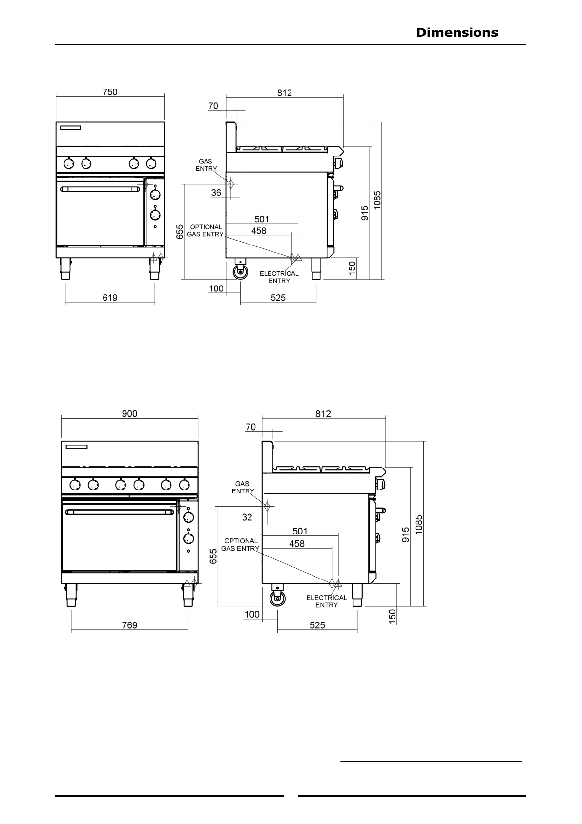
Gas supply connection point is located at rear of appliance:-
For GE505 / GE54, located approximately 130 m m from right hand side, 36mm from rear
and 655mm from floor and is reached from beneath appliance.
For GE506 / GE56, located approximately 130 m m from right hand side, 32mm from rear
and 655mm from floor and is reached from beneath appliance.
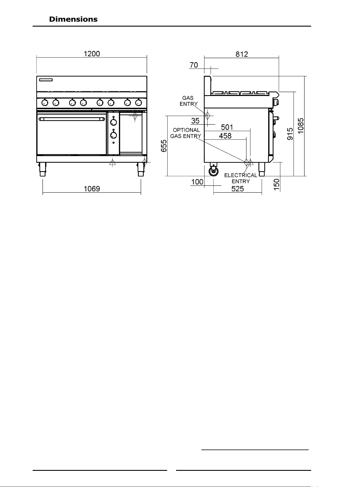
For GE508 / GE58, located approximately 130 m m from right hand side, 35mm from rear
and 655mm from floor and is reached from beneath appliance.
Connection is ¾" BSP male thread (for all other models).
Input Rate (N.H.G.C.)
- each Open Burner
28 MJ/hr
28 MJ/hr
- each 300mm Griddle Section 21 MJ/hr 21 MJ/hr
Supply Pressure
1.13 - 3.40 kPa 2.75 - 4.50 kPa
Burner Operating Pressure (*)
0.95 kPa 2.6 kPa
Gas Connection
See ‘Gas Connection’ information overleaf.
Input Rate (N.H.G.C.)
- each Open Burner
28 MJ/hr
28 MJ/hr
- each 300mm Griddle Section 21 MJ/hr 21 MJ/hr
Supply Pressure
1.13 - 3.40 kPa 0.75 - 1.50 kPa
Burner Operating Pressure (*)
0.95 kPa 0.63 kPa
Gas Connection
See ‘Gas Connection’ information overleaf.
6
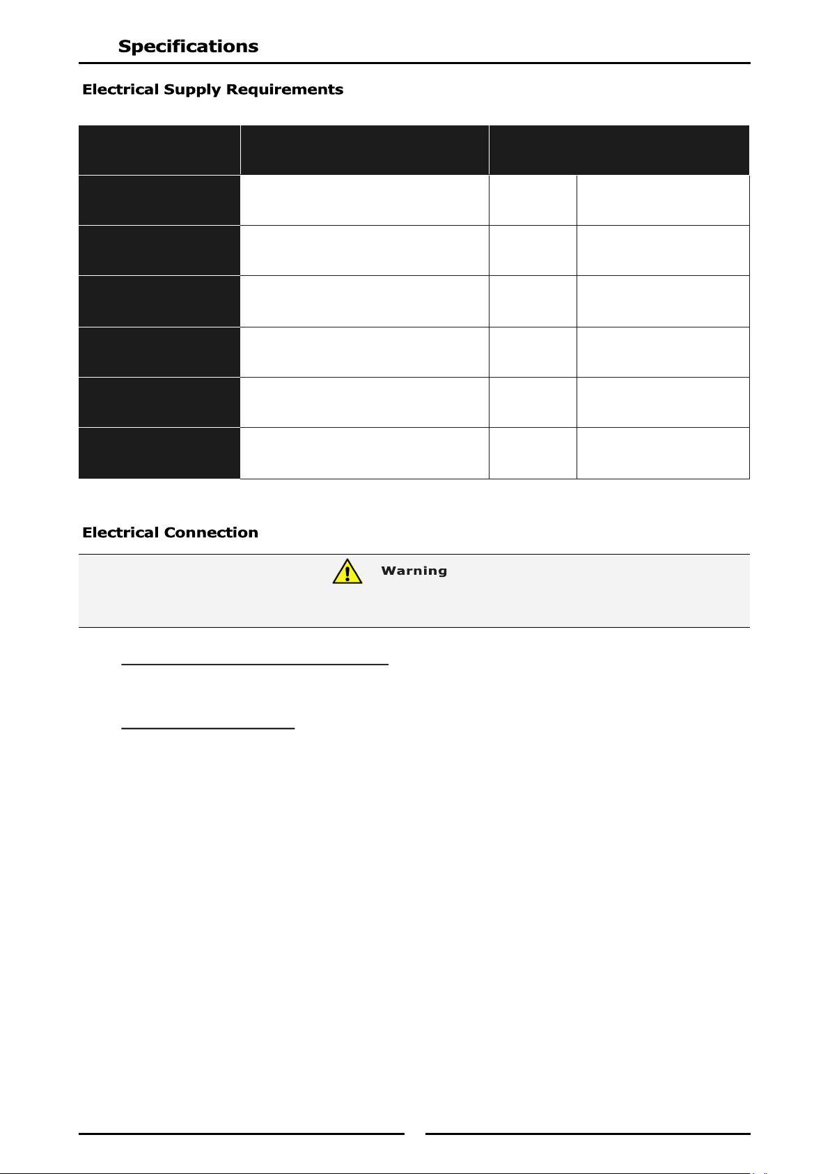
GE505 / 54 - GE506 / 56 Models Only.
Electrical supply connection point is located at rear of appliance, approximately 74mm from right
hand side, 501mm from rear and 150mm from floor.
GE508 / 58 Models Only.
Electrical supply connection point is located at rear of appliance, approximately 374mm from right
hand side, 501mm from rear and 150mm from floor.
When connecting this electric appliance to mains supply, ensure that the following is carried out:-
An isolating switch is fitted within 2m of appliance, but not on appliance and in such a position
that user does not have to reach across cooking surface.
Supply cord shall be oil-resistant, sheathed flexible cable and not lighter than ordinary
polychloroprene or other equivalent synthetic elastomer sheathed cord (as per AS/NZS 3191 part
2.10.11. or IEC 60245-IEC-57) e.g. HO5 RN-F Type.
Branch supply line shall be individually overload protected to correct current rating and supply
chord shall be protected against any mechanical or thermal damage.
A grommet is fitted around wiring entry hole into appliance.
All wiring connections must be tight.
Refer to appropriate wiring standards for size of cable to be supplied to an appliance for current
drawn on that line.
MODEL
1-Phase Connection
1P+N+E
230-240V
3-Phase Connection
3P+N+E
400-415V
GE505
5.5 kW,
22.6 Amps @ 235 V
5.5 kW
L1 - 7.2 Amps
L2 - 7.7 Amps
L3 - 7.7 Amps
GE54
5.8 kW,
23.9 Amps @ 235 V
5.8 kW
L1 - 8.5 Amps
L2 - 7.7 Amps
L3 - 7.7 Amps
GE506
6.5 kW,
26.6 Amps @ 235 V
6.5 kW
L1 - 8.2 Amps
L2 - 9.2 Amps
L3 - 9.2 Amps
GE56
6.8 kW,
27.9 Amps @ 235 V
6.8 kW
L1 - 9.5 Amps
L2 - 9.2 Amps
L3 - 9.2 Amps
GE508
6.5 kW,
26.6 Amps @ 235 V
6.5 kW
L1 - 8.2 Amps
L2 - 9.2 Amps
L3 - 9.2 Amps
GE58
6.8 kW,
27.9 Amps @ 235 V
6.8 kW
L1 - 9.5 Amps
L2 - 9.2 Amps
L3 - 9.2 Amps
THIS APPLIANCE MUST BE EARTHED. IF THE SUPPLY CORD IS DAMAGED, IT MUST BE REPLACED BY A SUITABLY
QUALIFIED PERSON IN ORDER TO AVOID A HAZARD.
7
Dimensions
GE505 / GE54
Refer to Page 8 for Cook Top Options
Dimensions
GE506 / GE56
8
Dimensions
GE508 / GE58
Refer to Page 8 for Cook Top Options
9
Cook Top Options GE506-D/GE56-D
Cook Top Options GE506-C/GE56-C
Cook Top Options GE506-B/GE56-B
Cook Top Options GE506-A/GE56-A
Cook Top Options GE508-D/GE58-D
Cook Top Options GE508-C/GE58-C
Cook Top Options GE508-B/GE58-B
Cook Top Options GE508-A/GE58-A
Cook Top Options GE505-D/GE54-D
Cook Top Options GE505-C/GE54-C
10
NOTE:
It is most important that this appliance is installed correctly and that operation is correct
before use. Installation shall comply with local electrical, gas, health and safety
requirements.
This appliance shall be installed with sufficient ventilation to prevent the occurrence of
unacceptable concentrations of health harmful substances in the room, the appliance is
installed in.
Blue Seal Convection Ovens are designed to provide years of satisfactory service, and correct installation is
essential to achieve the best performance, efficiency and trouble-free operation.
This appliance must be installed in accordance with National installation codes and in addition, in
accordance with relevant National / Local codes covering gas, electrical and fire safety.
Australia/ New Zealand: - AS/NZS5601 - Gas Installations.
- AS/NZS3000 - Wiring Rules.
United Kingdom: - Gas Safety (Installation & Use) Regulations 1998.
- BS6173 - Installation of Catering Appliances.
- BS5440 1 & 2 - Installation Flueing & Ventilation.
- BS7671 - Requirements for Electrical Installation.
Ireland: - IS 820 - Non - Domestic Gas Installations.
Installations must be carried out by authorised persons only. Failure to install equipment to
relevant codes and manufacturer’s specifications shown in this section will void the warranty.
Components having adjustments protected (e.g. paint sealed) by manufacturer are only to be
adjusted by an authorised service agent. They are not to be adjusted by the installation
person.
Remove all packaging and transit protection from appliance including all protective plastic coating
from exterior stainless steel panels.
Check equipment and parts for damage. Report any damage immediately to the carrier and
distributor.
Report any deficiencies to distributor who supplied the appliance.
Check that available gas and electrical supply is correct to that shown on rating plate located on front
right hand corner of bottom sill.
1. Installation must allow for a sufficient flow of fresh air for the combustion air supply.
2. Installation must include adequate ventilation means, to prevent dangerous build up of combustion
products.
3. Never directly connect a ventilation system to appliance flue outlet.
4. Position appliance in its approximate working position.
5. All air for burner combustion is supplied from beneath appliance. Legs must always be fitted and no
obstructions placed beneath or around base of appliance, as obstructions will cause incorrect
operation and / or failure of appliance.
NOTE: Do not obstruct or block appliance flue. Never directly connect a ventilation system to
appliance flue outlet.
Combustion Air Requirements:
GE505 / GE54 GE506 / GE56 GE508 / GE58
Natural Gas (G20)
24 m
3
/hr 36 m
3
/hr 48 m
3
/hr
LPG (G31)
25 m
3
/hr 38 m
3
/hr 50 m
3
/hr
Town Gas
24m
3
/hr 36m
3
/hr 48m
3
/hr
11
NOTE: Only non-combustible materials can be used in close proximity to this appliance.
* Side clearances can be 50mm when adjacent surface is at least 100mm below cooking surface.
All Models are delivered completely assembled. No further assembly is required.
This appliance is fitted with adjustable feet to enable the appliance to be positioned
securely and level. This should be carried out on completion of the gas connection. Refer
to the ‘Gas Connection’ section.
Optional Accessories (Refer to Replacement Parts List)
Plinth Kit. For installation details, refer to the instructions supplied with each kit.
1. Check that all the feet (or castors) are securely fitted.
2. Adjust the feet to make the Range steady and level.
NOTE: ALL GAS FITTING MUST ONLY BE CARRIED OUT BY AN AUTHORISED PERSON.
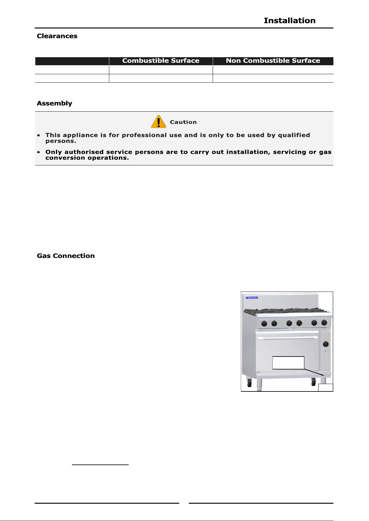
1. It is essential that gas supply is correct for appliance to be installed and that adequate supply
pressure and volume are available. The following checks should be made before installation:-
a. Gas Type the appliance has been supplied for is shown on
coloured stickers located above gas entry point and next to
rating plate. Check that this is correct for gas supply the
appliance is being installed for. Gas conversion procedure is
detailed in this manual.
b. Supply Pressure required for this appliance is shown in
‘Specifications’ section of this manual. Check gas supply to
ensure adequate supply pressure exists.
c. The Input Rate of this appliance is stated on Rating Plate and
in ‘Specifications’ section of this manual. Input rate should be
checked against available gas supply line capacity. Particular
note should be taken if appliance is being added to an
existing installation.
NOTE: It is important that adequately sized piping runs directly to connection joint on appliance
with as few tees and elbows as possible to give maximum supply volume.
2. Fit gas regulator supplied, into gas supply line as close to appliance as possible.
NOTE: Gas pressure regulator provided with this appliance is convertible between Natural Gas and
LPG as shown in ‘Gas Conversion Section’ in this manual.
Ensure regulator is converted to correct gas type that appliance will operate on.
Regulator outlet pressure is fixed ex-factory for gas type that regulator is converted to and
it is NOT to be adjusted.
Left / Right hand side 250mm (*) 0mm
Rear 50mm 0mm
Rating Plate
Location
Fig 1
12
Regulator connections are
3
/
4
" BSP female.
Connection to appliance is
3
/
4
" BSP male.
(Refer to ‘Specifications’ section for gas supply location dimensions).
NOTE: A Manual Isolation Valve must be fitted to individual appliance supply line.
3. Correctly locate appliance into its final operating position and using a spirit level, adjust legs so that
appliance is level and at correct height.
4. Connect gas supply to appliance. A suitable jointing compound which resists breakdown action of
LPG must be used on every gas line connection, unless compression fittings are used.
5. Check all gas connections for leakages using soapy water or other gas detecting equipment.
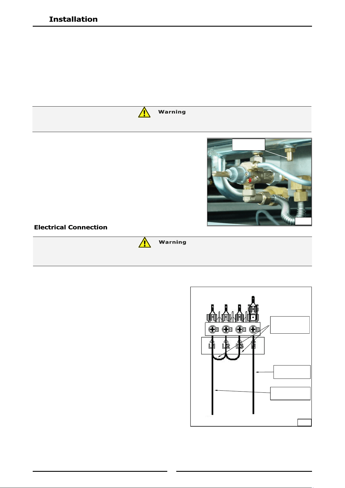
NOTE: Measure burner operating pressure at manifold test
point with two burners operating at ‘Full’ setting.
6. Check gas operating pressure is as shown in ‘Specifications’
section.
7. Verify operating pressure remains correct.
NOTE: ALL ELECTRICAL CONNECTIONS MUST ONLY BE CARRIED OUT BY AN AUTHORISED
PERSON.
Each appliance should be connected to an adequately
protected power supply and an isolation switch mounted
adjacent to, but not behind appliance. This switch must
be clearly marked and readily accessible in case of fire.
1. Check electricity supply is correct as shown on
Rating Plate attached to lower front hand side of
front sill panel.
2. Supply terminal connections are located at rear of
appliance. Refer to ‘Electrical Connections’ in
‘Dimensions’ section of manual.
3. Open oven door and remove oven control panel to
allow connection access for electrical supply.
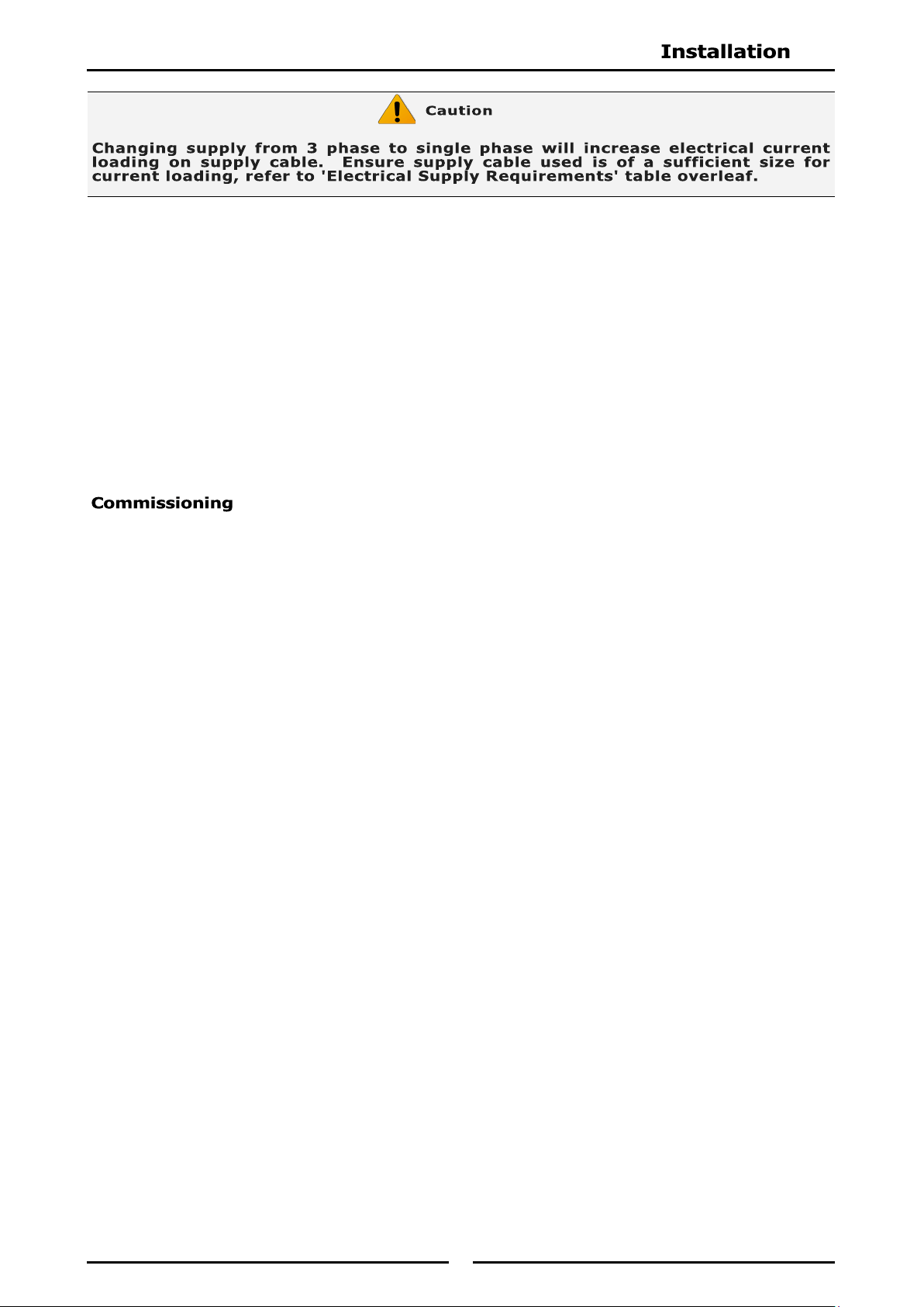
4. Connect mains supply to L1, L2 and L3 connection
terminals. Refer to 'Electrical Supply
Requirements' section for connection details.
NOTE: This appliance can be converted from 3 Phase to Single Phase supply by connecting single
phase input to L1 and adding a bridge wire between L1, L2 and L3 connections, (refer to Fig
3 above and information shown in 'Electrical Supply Requirements Table' in 'Specifications'
Section).
Fig 2
Manifold Test
Point
Add bridging
wires between
L1, L2 and L3.
Neutral sup-
ply connection
Phase supply
connection to L1
P
N
Fig 3
DO NOT USE A NAKED FLAME TO CHECK FOR GAS LEAKAGES.
THIS APPLIANCE MUST BE EARTHED. IF SUPPLY CORD IS DAMAGED, IT MUST BE REPLACED BY A SUITABLY
QUALIFIED PERSON IN ORDER TO AVOID A HAZARD.
13
5. Connect neutral and earth conductors to neutral stud and earth stud respectively.
6. For all connections ensure conductors are secure and appropriately terminated.
7. Tighten cable gland to secure against tension on cable.
8. Check that polarity of each connection is correct to mains connection terminals markings on
appliance.
NOTE:
This appliance must be earthed.
Fixed wiring installations must incorporate an all-pole disconnection switch.
9. Correctly locate appliance into its final operating position and using a spirit level, adjust legs so that
appliance is level and at correct height.
10. Connect power supply to the appliance.
11. Check that electrical supply is within input rating specification, refer to ‘Specifications’ section).
1. Before leaving a new installation;
a. Check following functions in accordance with operating instructions specified in ‘Operation’
section of this manual.
Light the Griddle.
Light the Open Burners. (F - Flame Failure Option).
Light the Open Burners. (PF - Pilot and Flame Failure Option).
Check the Low Fire Burner Operation.
Check the High Fire Burner Operation.
Check the Oven Heating.
Check the Oven Thermostat Operation.
Check the Oven Fan Operation (GEC Models only).
b. Ensure that operator has been instructed in areas of correct lighting, operation, and shutdown
procedure for appliance.
2. This manual must be kept by owner for future reference, and a record of
Date of Purchase,
Date of
Installation
and
Serial Number of Appliance
recorded and kept with this manual.
(These
details can be found on Rating Plate attached to front right hand corner of bottom sill.
Refer to ‘Gas Connection’ section).
NOTE: If for some reason it is not possible to get appliance to operate correctly, shut off gas
supply and contact supplier of this appliance.
14
1. Blue Seal appliances have been designed to provide simplicity of operation and 100% safety
protection.
2. Improper operation is almost impossible, however bad operation practices can reduce the life of the
appliance and produce a poor quality product. To use this appliance correctly please read the
following sections carefully:-
Lighting the Open Burners (PF - Pilot and Flame Failure Option).
Lighting the Open Burners (F - Flame Failure Option).
Lighting the Griddle.
Oven.
Heating Indicator
Lamps (Amber)
for Top &
Bottom Elements
Power Indicator
Lamp (White)
Griddle Option
Burner Control
๐ OFF Position
PILOT Burner
HIGH Flame
LOW Flame
Gas Control Knobs
Piezo Igniter
(Located here when fitted
with Griddle Option)
Open Burner Option
OFF Position
HIGH Flame
LOW Flame
Rear Burner
Front Burner
(Indicators located
above the Gas
Control Knobs).
Oven Top Heat Control
๐ OFF Position
LOW Position
1 Position
2 Position
3 Position
4 Position
HIGH Position
Fig 4
Oven Thermostat
Control
๐ OFF Position
Temperature
Graduations 50°C to
320°C
15
Lighting the Open Burners
Flame Failure Protection is incorporated for each burner by way of a thermo-electric system which
will shut off gas supply to that burner in the event that burner goes out, so that un-burnt gas is not
expelled.
a. Select burner required, depress and turn the gas control knob anti-clockwise to ‘HIGH’ position.
b. Hold gas control knob depressed and manually light main burner.
c. Release gas control knob after approximately 10-20 seconds after lighting burner.
d. Burner should stay alight - if not, repeat Steps (a. to (c. above.
e. To adjust the temperature required, depress and rotate gas control knob between ‘HIGH’ and
‘LOW’ positions.
Turning 'OFF' the Open Burners
a. When main burner is not required, depress and turn gas control knob clockwise back to ‘OFF’
position. 'MAIN' burner will extinguish.
Lighting the Open Burners
These hobs are fitted with individual standing pilots for each open burner which allows main burners
to be turned 'ON' - 'OFF' without having to manually re-light burner each time that it is turned 'ON',
as burner will automatically light itself off the pilot burner.
Flame Failure Protection is incorporated for each burner by way of a thermo-electric system which
will shut off gas supply to that burner in the event that burner goes out, so that un-burnt gas is not
expelled.
a. Select burner required, depress and turn the gas control knob anti-clockwise to ‘PILOT’ position.
b. Hold gas control knob depressed and manually light pilot burner.
c. Release gas control knob after approximately 10-20 seconds after lighting pilot burner.
d. Pilot burner should stay alight - if not, repeat Steps (b. to (c. above.
e. To select ‘Full Flame’, depress and rotate gas control knob anti-clockwise to first stop 'HIGH'
flame position.
f. To select ‘Low Flame’, depress and rotate gas control knob fully anti-clockwise to ‘LOW' flame
position.
g. To adjust the temperature required, depress and rotate gas control knob between ‘HIGH’ and
‘LOW’ positions.
Turning 'OFF' the Open Burners / Pilots
a. To turn 'OFF' main burner, but keep pilot burner alight, rotate gas control knob to 'PILOT'
position. Main burner will extinguish and pilot will remain alight.
b. To turn 'OFF' the 'PILOT', depress and turn gas control knob clockwise back to ‘OFF’ position.
'PILOT' burner will extinguish.
16
Lighting the Griddle
a. Depress gas control knob and rotate anti-clockwise to ‘PILOT’ position.
b. Hold gas control knob depressed, press piezo ignition button to ignite pilot burner. Repeat Items
1 to 2 until pilot is lit.
c. Release gas control knob approximately 10-20 seconds after lighting pilot.
d. Pilot should now remain alight - if not, repeat Steps (b. to (c. above.
e. To select ‘Full Flame’, depress and rotate gas control knob anti-clockwise to ‘HIGH’ position.
f. To select ‘Low Flame’, depress and rotate gas control knob fully anti-clockwise to ‘Low Flame’
position.
g. When main burner is not required, depress and turn gas control knob clockwise back to ‘OFF’
position.
Turning 'OFF' the Griddle Burner / Pilot
a. To turn 'OFF' griddle, but keep pilot burner alight, rotate gas control knob to 'PILOT' position.
Griddle burner will extinguish and pilot will remain alight.
b. To turn 'OFF' 'PILOT', depress and turn gas control knob clockwise back to ‘OFF’ position. 'PILOT'
burner will extinguish.
DO NOT USE aluminium foil or trays directly on cast iron sole plate(s).
NEVER block or cover openings on each side of sole plate(s).
1. Oven is fitted with top and bottom elements. The thermostat maintains oven temperature by
controlling both elements. Top element is further controlled by an energy regulator. Convection
Ovens are fitted with a circulation fan (GE54 / GE56 / GE58).
2. Place oven racks in desired position.
3. Preheat:- By selecting desired temperature, and turning oven top heat control to a maximum of 2.
When desired temperature is reached, amber neon will go out.
4. Cooking:- When desired temperature has been reached, turn top element control to ‘OFF’ position.
5. Top Heat:- To obtain more top heat during cooking, turn top heat control to ‘ON’ position. (The
higher the setting, the more top heat).
6. For Browning:- Turn oven top element control to maximum and oven temperature to a ‘LOW’
setting (about 120°C) or just above 'Light On' position, if previously working at higher temperatures.
7. Turning ‘OFF’ the Oven:- Turn oven top heat control to ‘O’ off position. Top heating will be
turned ‘OFF’ and upper heating indicator lamp (Amber) will extinguish.
Turn thermostat control knob to ‘O’ off position and lower heating indicator lamp will extinguish.
The oven is now turned ‘OFF’.
IMPORTANT:
Should any abnormal operation like;
- ignition problems,
- abnormal burner flame,
- burner control problems,
- partial or full loss of burner flame in normal operation, appliance requires IMMEDIATE
service by a qualified service person and should not be used until a service is carried out.
! IMPORTANT
17
NOTE:
Allow appliance to cool before commencing cleaning.
DO NOT use abrasive or strong caustic detergents as they could corrode or damage the
Cooktop.
Ensure that any detergent or cleaning material has been completely removed after each
cleaning.
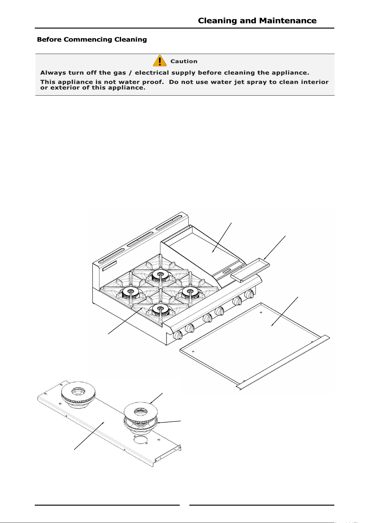
To keep your Cooktop clean and operating at peak efficiency, follow the procedures shown overleaf:-
Burner Body
Griddle Plate
Grease Tray
Spill Tray
Pot Stand
Burner Cap
Burner Mounting Rail
18
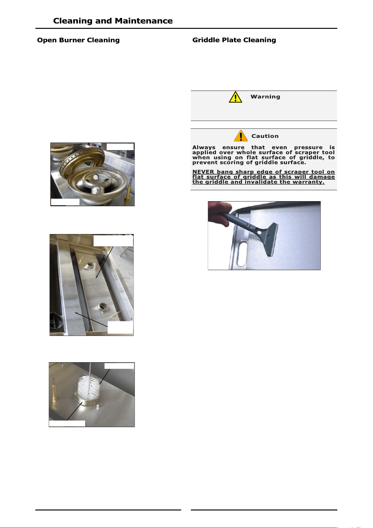
1. Remove pot stands, burner caps, burner bowls
and pot stand supports from top of cooktop.
Wash with hot soapy water, using a soft
bristled brush. Dry thoroughly with a dry cloth.
Any baked-on deposits can be scraped off
using a scraper tool.
NOTE: Pot stands, burner bowls and pot stand
supports can be washed in a dish
washer. Do Not wash burner caps in
dishwasher.
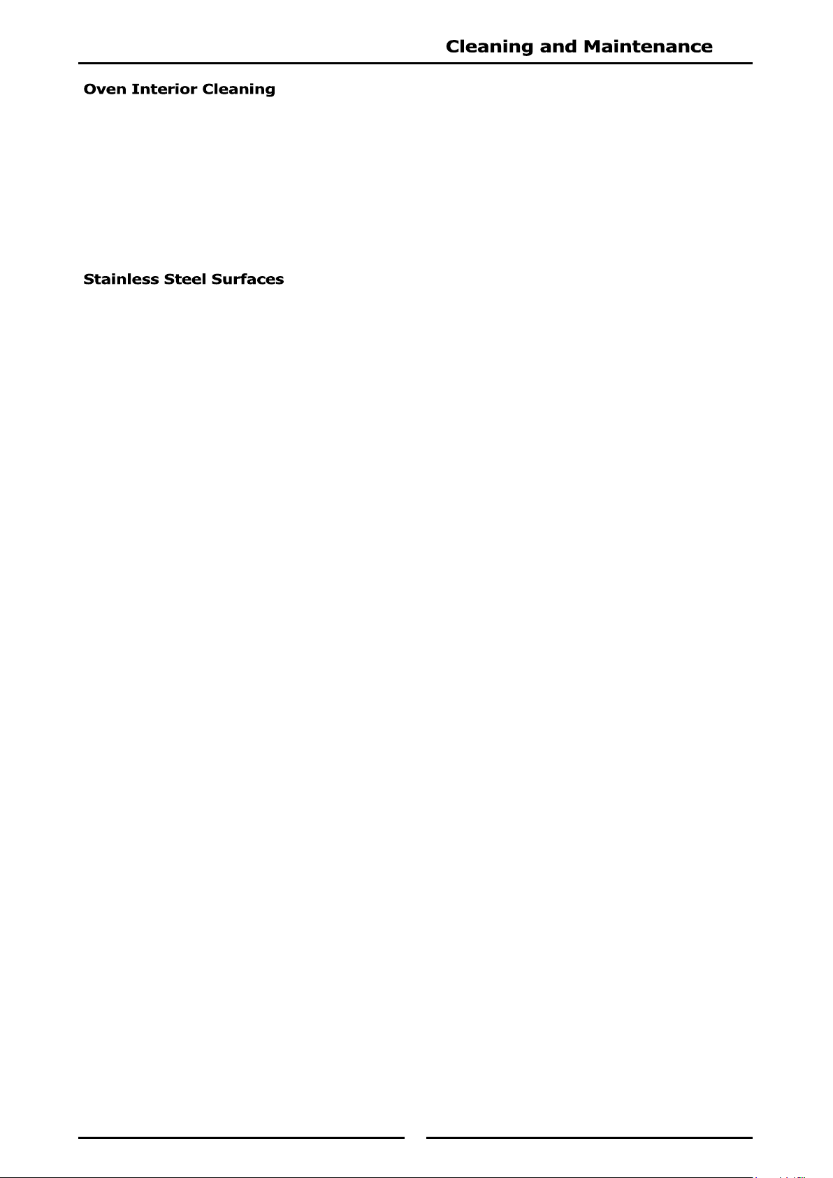
2. Burner mounting rails should not be removed.
Clean in situ with hot soapy water.
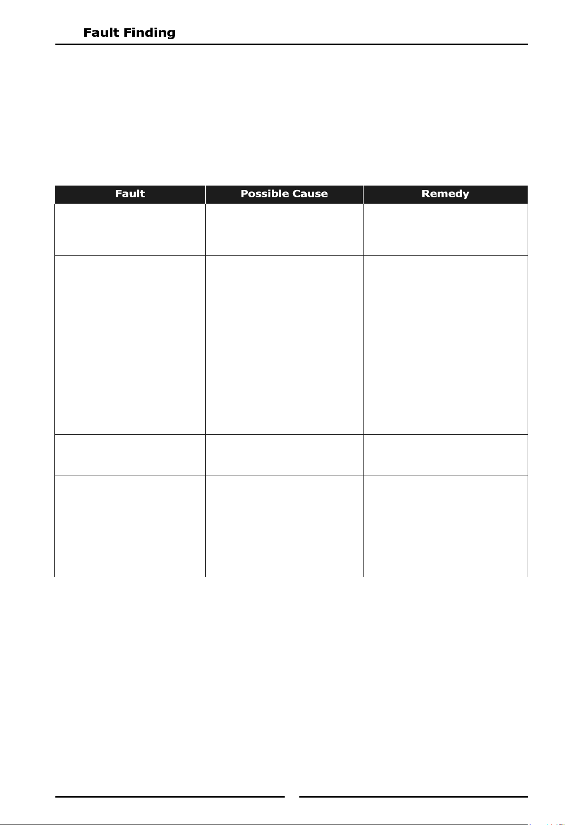
3. Clean burner venturi with a bottle brush and
hot soapy water, as required.
4. Empty spill tray and wash with warm soapy
water.
5. Dry all components thoroughly and
re-assemble.
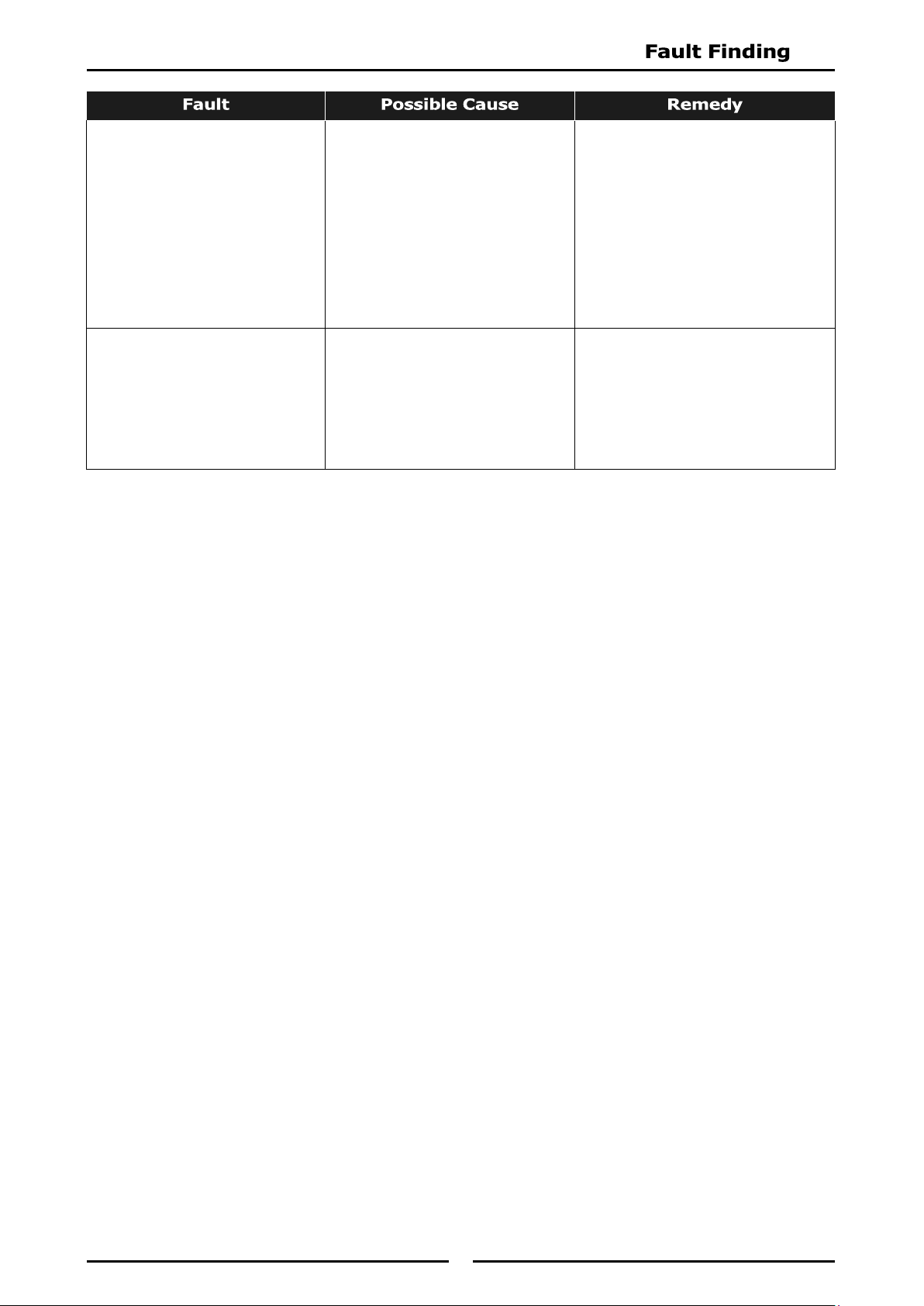
It is recommended that a flat blade scraper is used
to clean the griddle surface, these are not supplied
with griddle but may be purchased separately.
Refer to 'Replacement Parts List' at rear of this
manual.
1. Clean griddle plate surface thoroughly with a
scraper tool and brush off any deposits with a
soft bristled brush.
2. Stubborn or accumulated carbon deposits can
be removed with a griddle stone or a scotch
bright pad.
3. Wipe down griddle surface with a cloth and
then clean with hot soapy water and a soft
bristled brush. Dry thoroughly with a dry cloth.
4. Occasionally bleach griddle plate with vinegar
when plate is cold.
5. Empty grease tray and wash with warm soapy
water. Dry thoroughly with a dry cloth. Refit
grease tray.
6. Briefly turn ‘On’ griddle until griddle plate is
dry.
7. Spread a thin smear of cooking oil over griddle
plate to form a protective film.
THE BLADES FITTED TO THE SCRAPER TOOL ARE
EXTREMELY SHARP AND ARE TO BE USED WITH CARE.
Burner Cap
Burner Body
Burner Mounting
Rail
Pot Stand
Support
Burner Venturi
Bottle Brush
19
1. Do not use wire brushes, steel wool or other
abrasive materials to clean oven interior.
2. Clean oven regularly with a good quality
domestic oven cleaner.
3. Weekly - Remove and clean any built up of
grease etc. from oven racks and bottom spill
cover.
4. Dry oven thoroughly with a dry cloth and polish
with a soft dry cloth.
1. Clean stainless steel surfaces with hot soapy
water and a soft bristled brush.
2. Baked on deposits or discolouration, use a
good quality stainless steel cleaner or stainless
steel wool. Always rub in direction of grain.
20
This section provides an easy reference guide to more common problems that may occur during operation
of your appliance. The fault finding guide in this section is intended to help you correct, or at least
accurately diagnose problems with your equipment.
Although this section covers most common problems reported, you may encounter a problem not covered
in this section. In such instances, please contact your local authorised service agent who will make every
effort to help you identify and resolve the problem. Please note that the service agent will require the
following information:-
Model, Trade Name and Serial Number of Appliance. (both can be found on Technical
Data Plate located on the appliance.
Pilot won’t light. No gas supply.
Blocked pilot injector.
Ensure gas isolation valve is turned
on, and bottles are not empty.
Call service provider.
Pilot goes out when gas control
knob released. (Griddle option
only).
Releasing knob before
thermocouple has heated.
Pilot flame too small.
- Gas pressure too low.
- Partially blocked pilot injector.
Thermocouple connection to gas
control is loose or faulty.
Thermocouple faulty.
Electromagnet in rear of gas
control unit is faulty.
Hold knob in for at least 20
seconds following ignition of pilot.
Clean or replace pilot injector.
Tighten thermocouple connection.
Check thermo couple is producing
between 20-30mV.
Inspect and replace if not in good
working order.
Call service provider.
Main burner will not light. Incorrect supply pressure.
Faulty gas control.
Call service provider.
Piezo Ignition spark is being
generated but not sparking
from ignition electrode to pilot
burner hood. (Griddle option
only).
HT lead damaged or broken.
Check ignition electrode is not
cracked and is correctly
positioned.
Piezo igniter faulty.
Repair or replace HT lead.
Re-position or replace ignition
electrode.
Replace piezo igniter.
Call service provider.
21
Element does not work when
turned ‘ON’.
Check individual fuses located
behind control panel.
Check for electrical short by
checking there is NO continuity
between any ‘Phase In’ line and
metal appliance body itself.
Check for item failing (element,
control etc) by using a multi-
meter as shown on following
pages.
Replace blown fuse.
Call service provider.
Call service provider.
Complete power failure of the
appliance
Check fuse connection at the
mains supply.
Ensure fuse size is correct to
carry the load.
Check for electrical short to the
appliance.
Replace blown fuse.
Carry out a continuity and
resistance check on appliance.
Call service provider.
NOTE: Components having adjustments protected (e.g. paint sealed) by manufacturer, are only to
be adjusted by an authorised service agent. They are not to be adjusted by an
unauthorised service person.
22
23
24
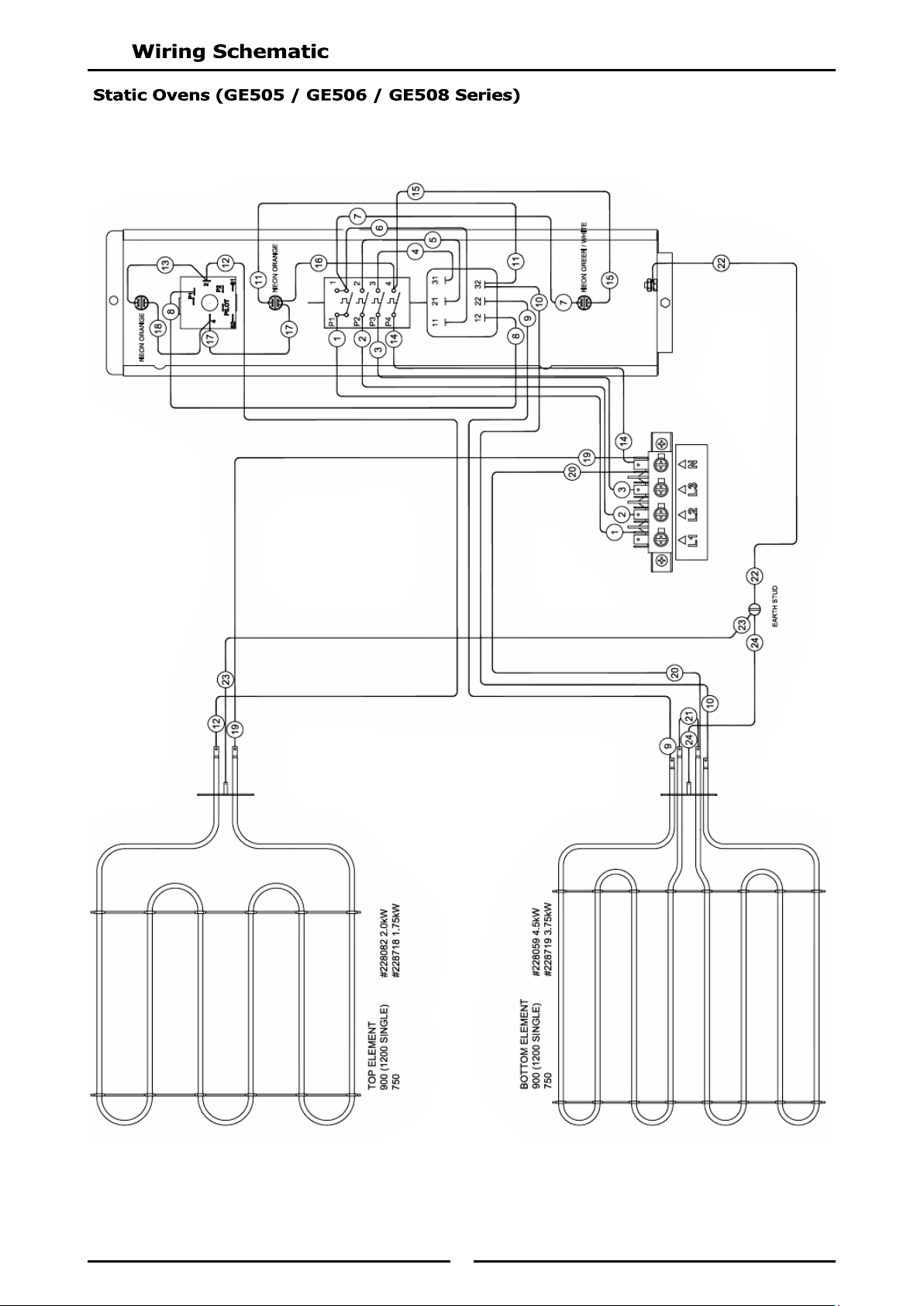
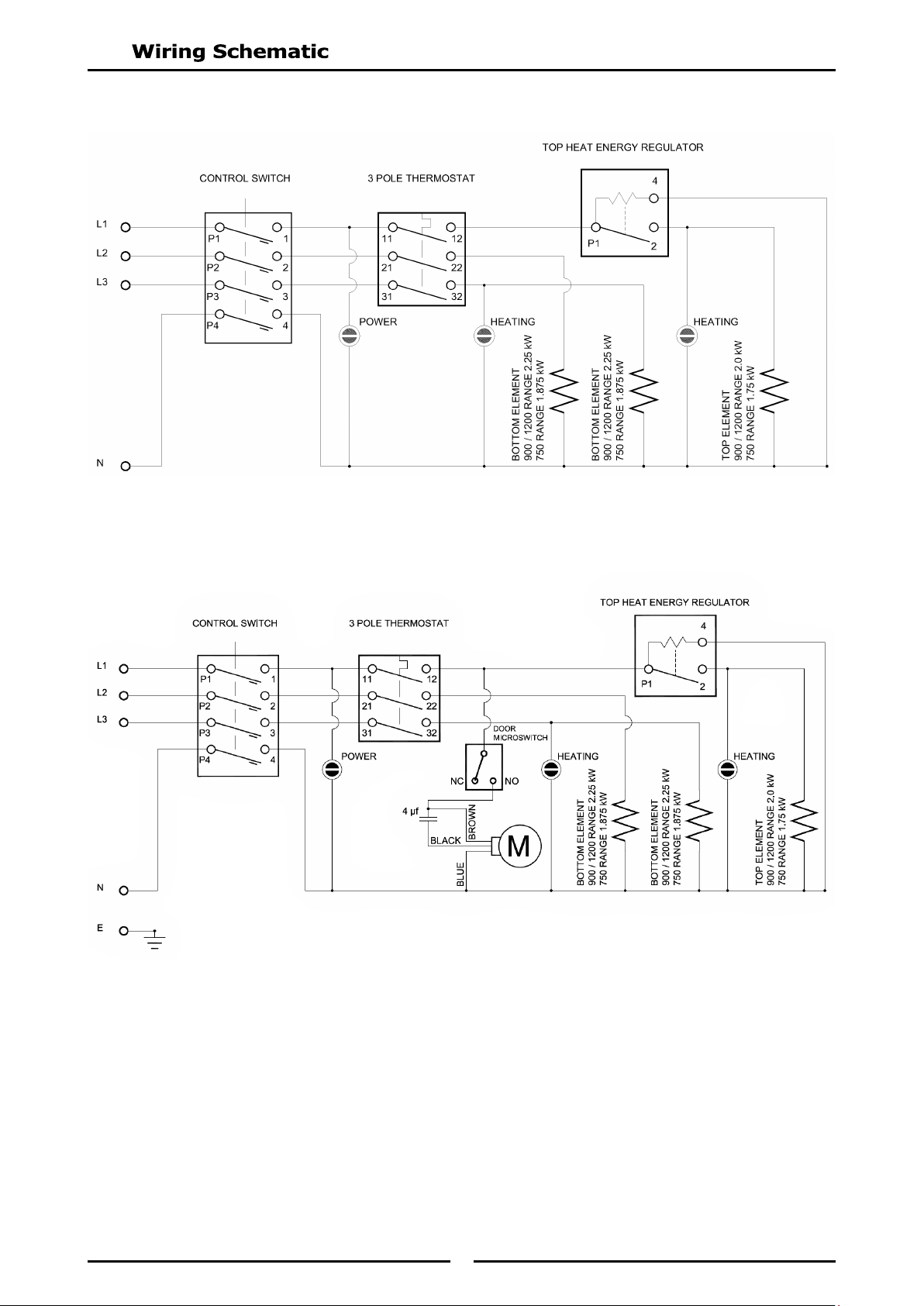
Wiring Layout for Static Oven
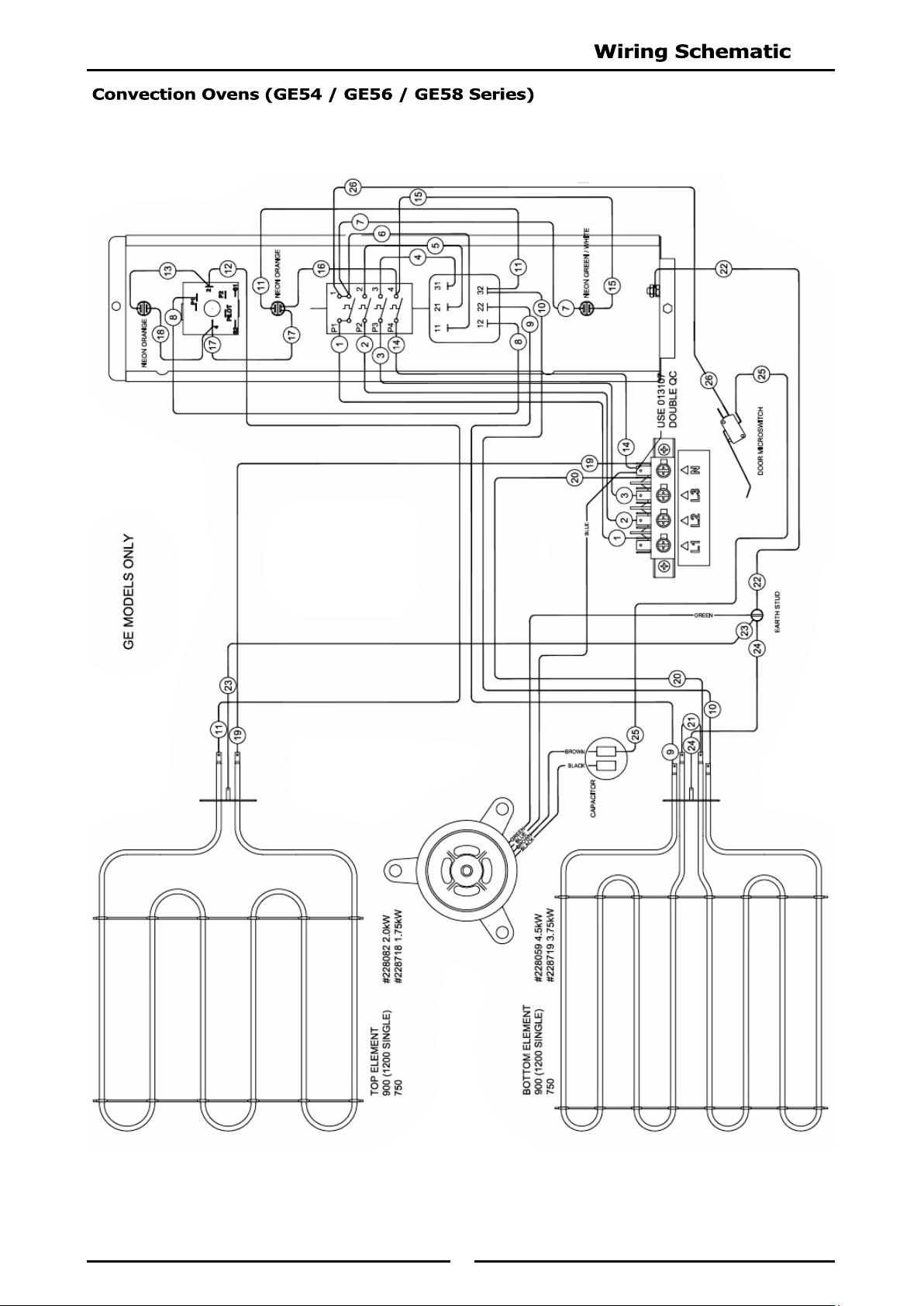
Wiring Layout for Convection Oven
25
NOTE:
These conversions should only be carried out by qualified persons. All connections must be
checked for leaks before re-commissioning the appliance.
Adjustment of components that have adjustments / settings sealed (e.g. paint sealed) can only be
adjusted in accordance with the following instructions and shall be re-sealed before
re-commissioning this appliance.
For relevant gas specifications refer to ‘Gas Specifications Tables’ at end of this section.
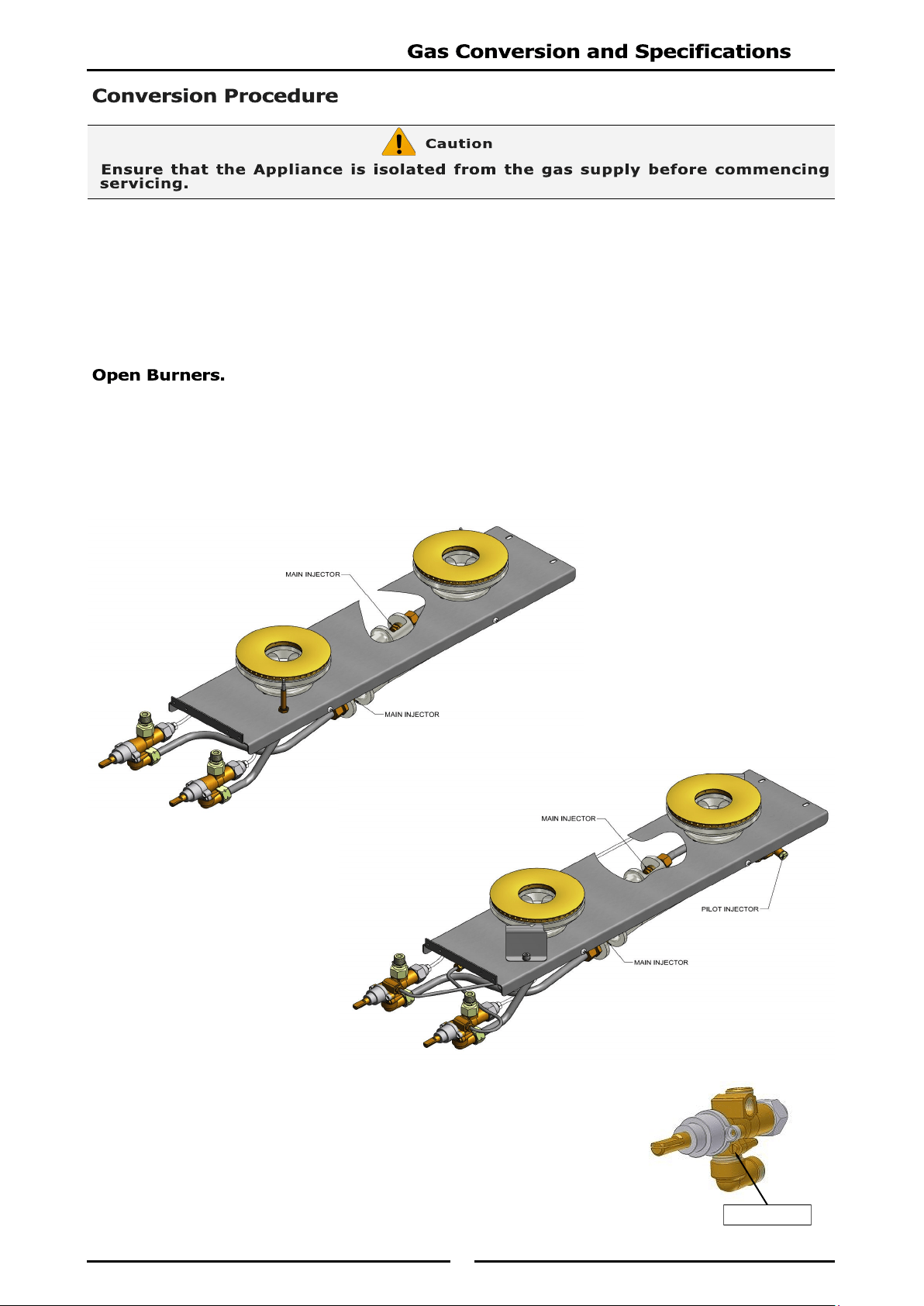
1. Remove the pot stands, burner caps and burner bodies and the pot stand supports.
2. Remove injectors and replace with correct size injectors as shown in ‘Gas Specifications Tables’ at
end of this section.
3. Refit the pot stand supports,
pot stands, burner caps and
burner bodies.
4. Re-light main burners and
check flame size on simmer
(LOW) position.
Adjust low fire adjustment screw on open burner gas control valves to
obtain desired flame size.
NOTE: The 'Low Fire Screw' should be sealed with coloured paint on
completion of low fire adjustment.
Low Fire Screw
For F Options Only,
Unscrew and remove Main Injectors.
For PF Options Only,
Unscrew and remove Main and
Pilot Injectors.
26
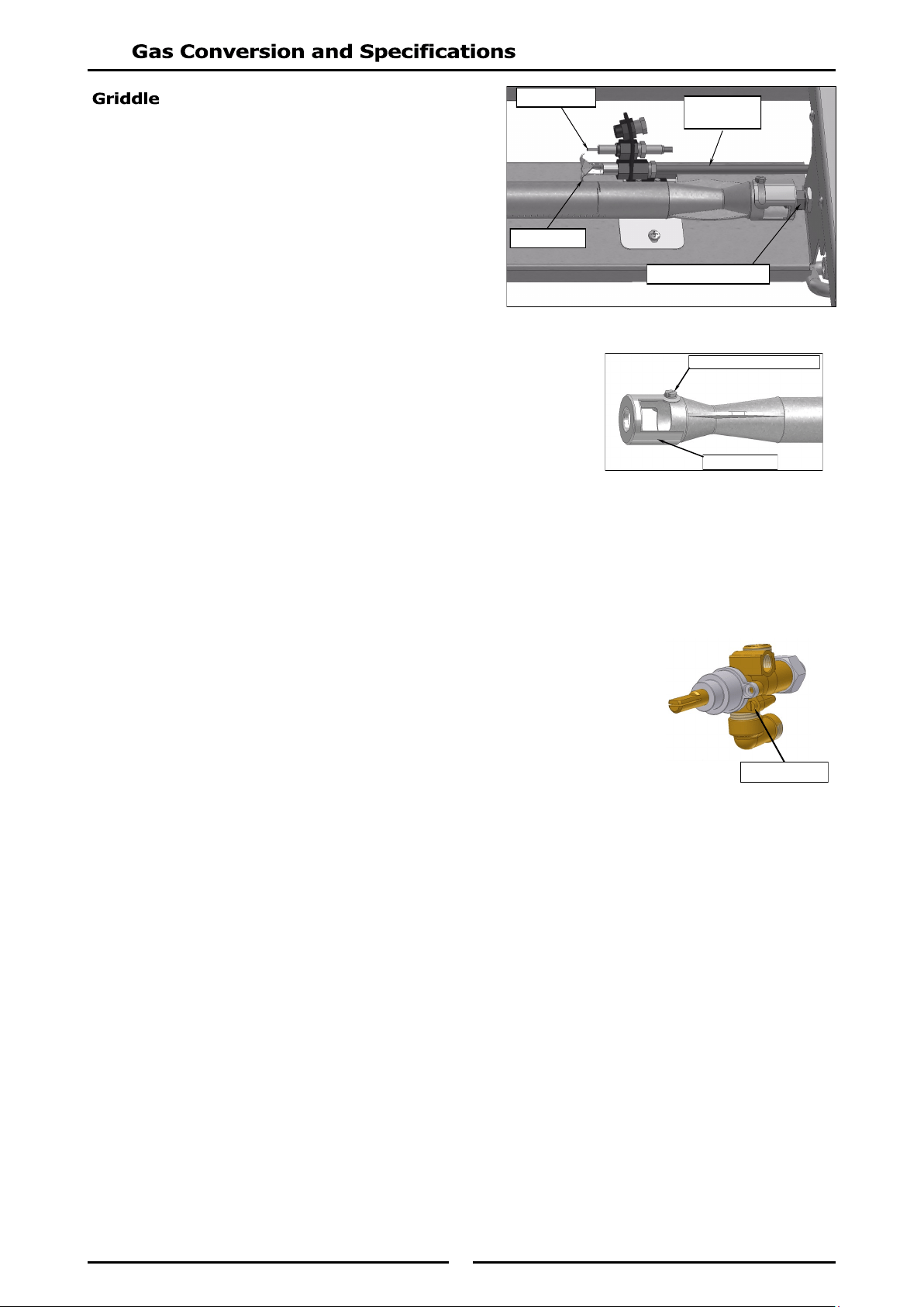
1. Carry out the following:-
Remove griddle plate section and heat
shield.
Remove main burner.
Disconnect piezo igniter from mounting
bracket. (For access purposes).
Disconnect pilot supply tube from pilot
burner to access pilot injector.
2. With Main Burner removed, ensure aeration gap is adjusted for
type of gas being used as shown in ‘Gas Specifications Tables’
at rear of this section.
3. Remove pilot and main injectors and replace with correct size
injectors as shown in ‘Gas Specifications Tables’ at rear of this
section.
4. Refit the following:-
Re-connect pilot supply tube to pilot burner.
Re-connect piezo igniter to mounting bracket.
Refit main burner, gas control heat shield and griddle plate to cooktop.
5. Re-light main burners and check flame size on ‘Low’ flame position.
Adjust low fire adjustment screw on open burner gas control valves to
obtain desired flame size.
NOTE: The 'Low Fire Screw' should be sealed with coloured paint on
completion of low fire adjustment.
Main Burner Injector
Pilot Supply
Tube
Pilot Burner
Piezo Igniter
Low Fire Screw
Burner Adjustment Screw
Aeration Slide
27
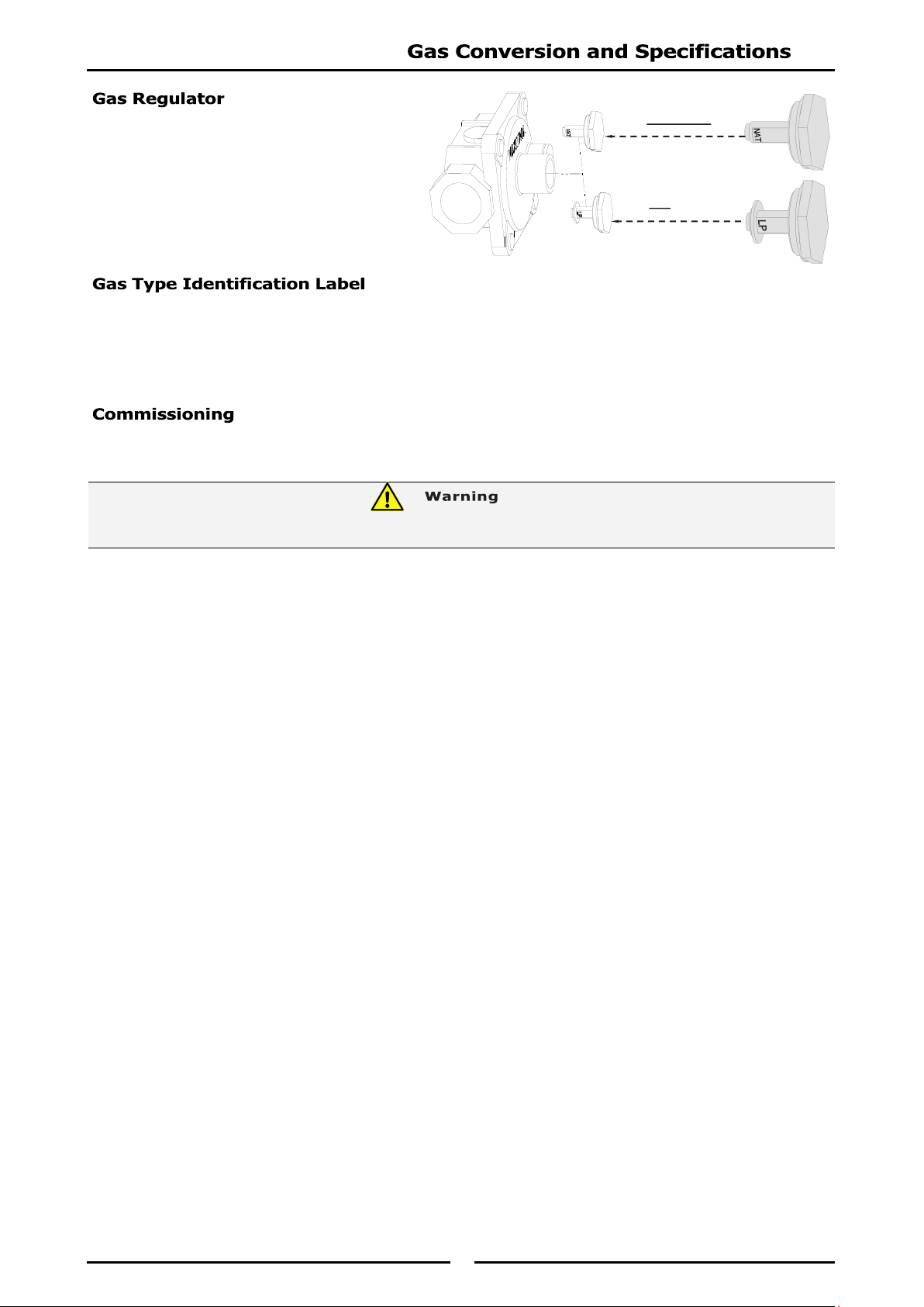
NOTE: The gas regulator supplied is
convertible between Natural
Gas and LP Gas, but it’s outlet
pressure is fixed ex-factory
and is NOT to be adjusted.
On completion of gas conversion, replace gas type identification label located at:-
- Rear of appliance, above gas connection.
- Beside the rating plate.
Before leaving the installation;
1. Check all gas connections for leakage using soapy water or other gas detecting equipment.
2. Carry out a ‘Commissioning’ check of appliance as shown in Installation Section of this manual.
3. Ensure any paint sealed components are re-sealed on completion of adjustments.
NOTE, Pin rotated
for Natural Gas
NOTE, Pin rotated
for LPG
DO NOT USE A NAKED FLAME TO CHECK FOR GAS LEAKAGES.
28
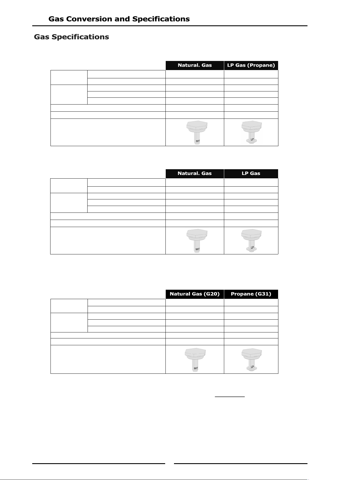
- Australia
- New Zealand
- United Kingdom
Category: II
2H3P
(20, 37).
Flue Type: A
1.
NOTE: Measure burner operating pressure at manifold test point with two burners operating at full setting.
Operating pressure is ex-factory set, through appliance regulator and is not to be adjusted, apart
from when carrying out Gas Conversion, if required. (Refer to ‘Gas Conversion’ section for details).
Open Burner
Main Burner Injectors Ø 2.30mm Ø 1.40mm
Pilot Burner ('PF' Models only) 0.30 0.20
Griddle
Main Burner Ø 2.10mm Ø 1.30mm
Pilot Burner 0.35 0.23
Burner Aeration Setting Fully open Fully open
Supply Pressure 20 mbar 37 mbar
Burner Operating Pressure (*) 9.5 mbar 26 mbar
Gas Regulator Cap Screw
Open Burner
Main Burner Ø 2.45mm Ø 1.50mm
Pilot Burner ('PF' Models Only) 0.30 0.20
Griddle
Main Burner Ø 2.10mm Ø 1.30mm
Pilot Burner 0.35 0.23
Burner Aeration Setting Fully open Fully open
Supply Pressure 1.13 - 3-40 kPa 2.75 - 3-40 kPa
Burner Operating Pressure (*) 0.95 kPa 2.6 kPa
Gas Regulator Cap Screw
Open Burner
Main Burner Ø 2.45mm Ø 1.40mm
Pilot Burner ('PF' Models Only) 0.30 0.20
Griddle
Main Burner Ø 2.10mm Ø 1.30mm
Pilot Burner 0.35 0.23
Burner Aeration Setting Fully open Fully open
Supply Pressure 1.13 - 3-40 kPa 2.75 - 3-40 kPa
Burner Operating Pressure (*) 0.95 kPa 2.6 kPa
Gas Regulator Cap Screw
29
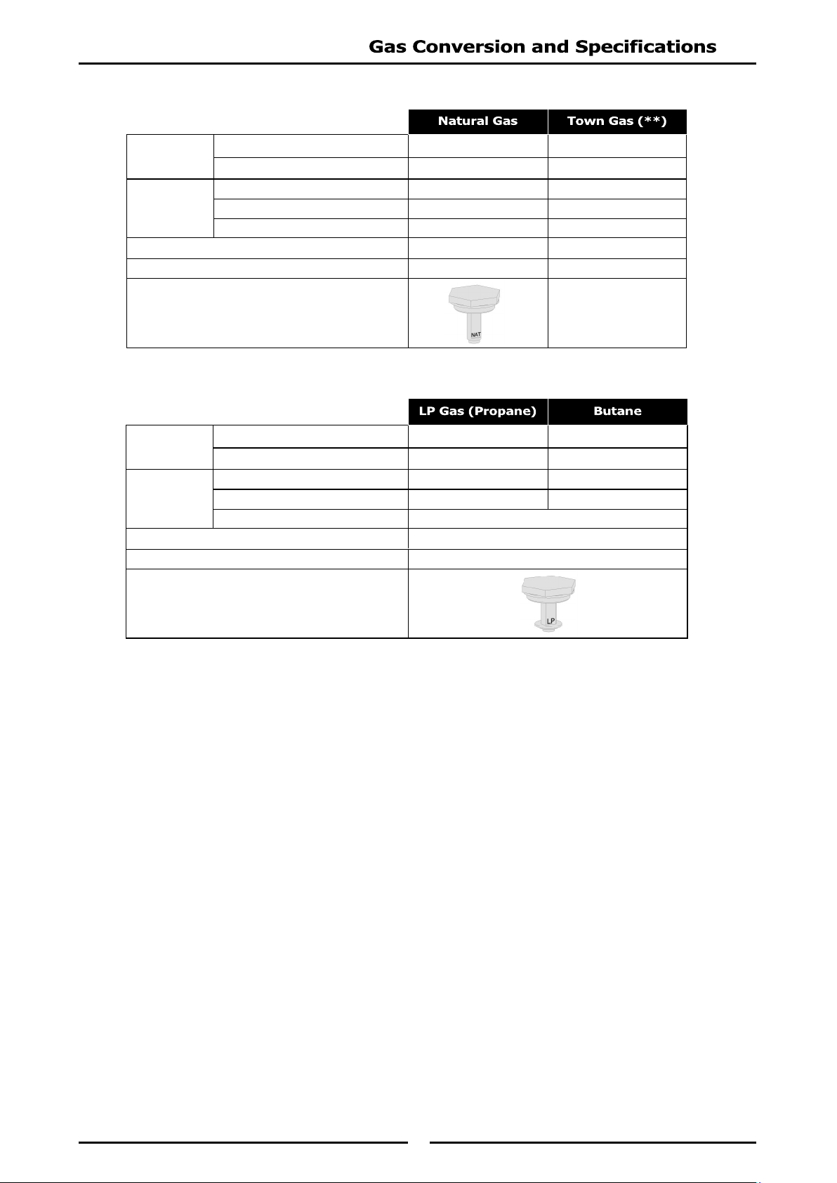
- All Other Markets
NOTE:
(*) Measure Burner operating pressure at manifold test point with two burners operating at
'High Flame' setting.
NAT, LPG & Butane Only - Operating pressure is ex-factory set and is not to be adjusted,
unless when converting between gases, if required.
(**) TOWN GAS Only - Adjust burner operating pressure using adjustable gas regulator
supplied.
Open Burner
Main Burner Ø 2.45mm Ø 4.50mm
Pilot Burner ('PF' Models only) 0.30 0.60
Griddle
Main Burner Ø 2.10mm Ø 3.40mm
Pilot Burner 0.35 0.60
Burner Aeration Setting Fully open Fully open
Supply Pressure 1.13 - 3-4 kPa 0.75 - 1.5 kPa
Burner Operating Pressure (*) 0.95 kPa 0.63 kPa
Gas Regulator Cap Screw
Adjustable Regulator
(Adjust to the Burner
Operating Pressure
specified)
Open Burner
Main Burner Ø 1.50mm Ø 1.40mm
Pilot Burner ('PF' Models only) 0.20 0.20
Griddle
Main Burner Ø 1.30mm Ø 1.40mm
Pilot Burner 0.23 0.23
Burner Aeration Setting Fully open
Supply Pressure 2.75 - 4.5 kPa
Burner Operating Pressure (*) 2.6 kPa
Gas Regulator Cap Screw
30
Replacement Parts List
When ordering replacement parts, please quote part number and description as listed below. If part
required is not listed below, request part by description and quote model number and serial number
which is shown on rating plate.
Cook Top
Open Burners
235678 Burner Body.
227017 Burner Cap.
030245 Injector (Nat. Gas) Ø 2.45mm. (Non-UK)
030150 Injector (LP Gas [Propane]) Ø 1.50mm. (Non-UK)
030230 Injector (Natural Gas - G20) Ø 2.30mm (UK Only).
030140 Injector (Propane / Butane) Ø 1.40mm (UK Only).
032450 Burner Injector (Town Gas) Ø 4.50mm.
026134 Pilot Injector (Nat Gas) 0.30.
026136 Pilot Injector (LP Gas [Propane]) 0.20.
t.b.d. Pilot Injector (Town Gas) 0.60.
229442 Pilot Bracket Assembly.
229444 Pilot Burner Shield.
227403 Gas Control (with Pilot and Flame Failure).
227405 Gas Control (with Flame Failure).
227378 Knob - Open Burner (with Pilot).
227379 Knob - Open Burner (Standard).
235711 Thermocouple - Front (200mm - Front).
235710 Thermocouple - Rear (600mm - Rear).
Griddle
014105 Burner.
032210 Injector (Nat. Gas) Ø 2.10mm.
032130 Injector (LP Gas [Propane]) Ø 1.30 mm.
032120 Injector (Butane) Ø 1.20mm
032340 Injector (Town Gas) Ø 3.40mm.
227403 Gas Control (with Flame Failure and Pilot).
227378 Knob - Griddle.
019215 Pilot Burner.
026488 Pilot Injector (Nat. Gas) 0.35.
019217 Pilot Injector (LP Gas / Butane) 0.23.
018067 Pilot Injector (Town Gas) 0.60.
019428 Thermocouple.
227508 Piezo Ignitor.
228047 Piezo H.T. Lead.
018744 Piezo Ignition Electrode.
228288 Grease Tray (Griddle Plates).
IMPORTANT:
31
Oven
228718 Oven Top Element 1.75kW (750 Ovens).
228719 Oven Bottom Element 3.75kW (750 Ovens).
228082 Oven Top Element 2kW (900 - 1200 Ovens).
228059 Oven Bottom Element 4.5kW (900 - 1200 Ovens).
228704 Door Spring Kit.
229021 Terminal Block Mains.
227392 Control Knob Thermostat 50°C - 300°C.
229146 Thermostat 50 - 300°C.
229145 Switch (4-pole).
013989 Energy Regulator.
227391 Control Knob HI/LO Heat.
Convection Oven Only
228938 Oven Door Microswitch.
010909 Motor Capacitor 4µf.
228116 Fan.
019479K Motor Kit.
General
227014 Pot Stand.
228884 Spill Tray (GE505 & GE54 only).
233515 Spill Tray (GE506 & GE56 only).
233517 Spill Tray LH (GE508 & GE58 only).
233518 Spill Tray RH (GE508 & GE58 only).
227892 Side Rack LH.
227893 Side Rack RH.
227896 Oven Rack.
228571 Index Mark Moulding.
227963 Neon Orange.
228922 Neon White.
227850 Adjustable Leg - 150mm.
229674 Rear Roller Assy.
Accessories
228566 Griddle Scraper Tool.
228567 Smooth Plate Scraper Blades (Pack of 2 Blades).
228568 Ribbed Plate Scraper Blade (Individual Blade).
228797 750mm Plinth Kit.
228800 900mm Plinth Kit.
228804 1200mm Plinth Kit.
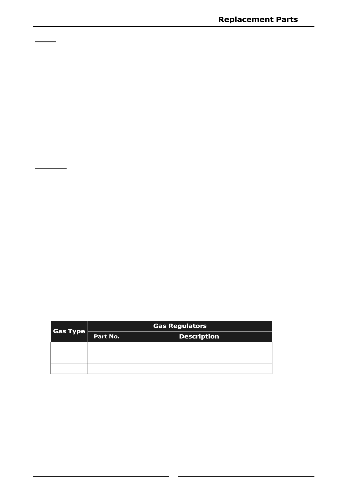
Gas Regulators
Nat. Gas
LPG
Butane
228531 ¾” BSP F/F Convertible.
Town Gas 230185 ¾” BSP F/F Adjustable.
32
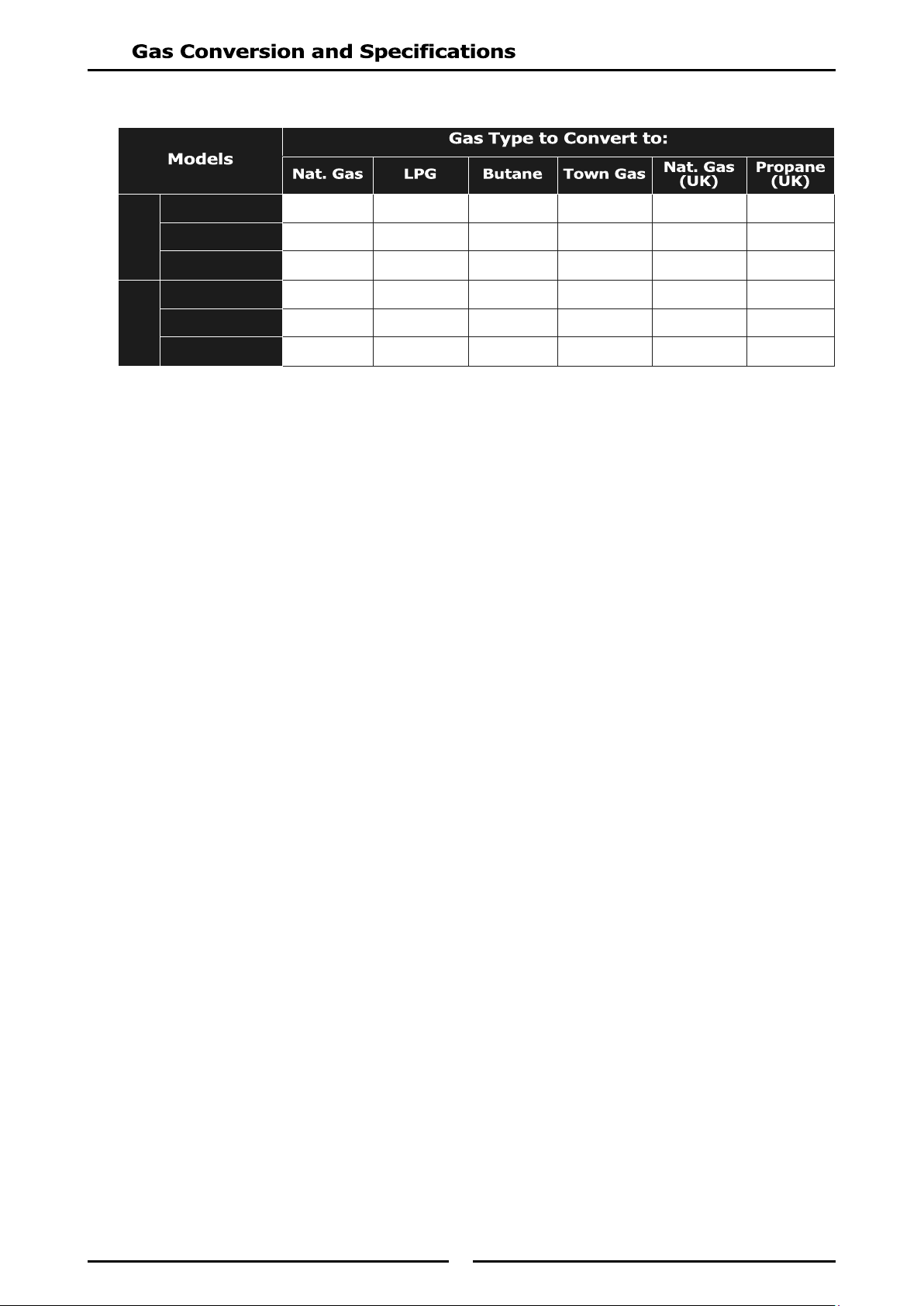
Gas Conversion Kits
NOTE: Each gas conversion kit is universal for all hob open burners and griddle variations possible
within the model specified.
GE505 / GE54 231841 231840 231842 231843 231871 231870
GE506 / GE56 231845 231844 231846 231847 231873 231872
GE508 / GE58 231849 231848 231850 231851 231875 231874
GE505 / GE54 231857 231856 231858 231859 231879 231878
GE506 / GE56 231861 231860 231862 231863 231881 231880
GE508 / GE58 231865 231864 231866 231867 231883 231882
'PF' Models
'F' Models