
1
Owner’s Manual
NetDirector
®
Rack-Mount
Console KVM Switch with
IP Access
Models: B030-008-17-IP, B030-DP08-17DIP, B030-DP16-17DIP
WARRANTY REGISTRATION
Register your product today and be
automatically entered to win an ISOBAR
®
surge protector in our monthly drawing!
tripplite.com/warranty
1111 W. 35th Street, Chicago, IL 60609 USA • tripplite.com/support
Copyright © 2022 Tripp Lite. All rights reserved.

2
Table of Contents
1. FCC Information ............................................................. 4
2. User Notice .................................................................... 4
3. Package Contents ......................................................... 4
4. Features ........................................................................ 5
5. System Requirements ................................................... 6
5.1 Built-in LCD Console .............................................. 6
5.2 Optional External Console ...................................... 6
5.3 Computers ............................................................. 6
5.4 Operating Systems ................................................ 6
5.5 Components .......................................................... 6
6. Important Safety Instructions ....................................... 8
6.1 General Safety Instructions ................................... 8
6.2 Rack-Mounting Safety Instructions ........................ 9
7. Installation ................................................................. 10
7.1 Standard Rack Mounting ..................................... 10
7.2 2-Post Rack Mounting ......................................... 10
7.3 Grounding ............................................................ 10
7.4 KVM Switch Installation ....................................... 10
7.5 Opening/Closing the Console ............................... 11
7.5.1 Opening Separately ...................................11
7.5.2 Opening Together ...................................... 12
7.5.3 Opening Precautions ..................................13
7.5.4 Closing the Console ................................... 14
7.6 Network Setup – IP Address Configuration ........... 16
7.6.1 Local Console ...........................................16
7.6.2 IP Installer ................................................17
7.6.3 Browser ....................................................17
8. Basic Operation ........................................................... 19
8.1 LCD OSD Configuration ........................................ 19
8.1.1 LCD Buttons .............................................19
8.1.2 Adjustment Settings ..................................19
8.1.3 Hot Plugging .............................................19
8.1.4 Powering Off and Restarting ........................19
8.1.5 USB Peripheral Devices ..............................19
9. KVM Operation ............................................................. 20
9.1 Local Console ...................................................... 20
9.1.1 Local Console Login ...................................20
9.1.2 Local Console OSD Hotkey Sequence .......... 20
9.1.3 OSD Main Menu .......................................20
9.1.4 OSD Navigation .........................................21
9.1.5 OSD Functions ..........................................21
10. Logging In to the KVM over IP ..................................... 28
10.1 Web Browser ...................................................... 28
10.2 AP Windows Client Login ...................................... 28
10.3 AP Java Client Login ............................................ 31
11. KVM Web Interface ...................................................... 32
11.1 Web Interface Main Page ..................................... 32
11.1.1 Tab Bar .................................................... 33
11.2 Port Access ......................................................... 33
11.2.1 Connections .............................................33
11.2.2 Port Selection List .....................................35
11.2.3 Port Naming..............................................35
11.3 Web Interface Icons and Controls ........................ 36
11.4 Interactive Display Panel ..................................... 36
11.4.1 Device Level .............................................36
11.4.2 Port Level .................................................37
11.5 History ................................................................ 37
11.6 Favorites ............................................................. 38
11.7 User Preferences ................................................. 40
11.8 Sessions ............................................................. 41
11.9 Access ................................................................ 41
11.10 Port Configuration ............................................... 42
11.11 Associated Link ................................................... 44
11.12 User Management ............................................... 44
11.12.1 Device Assignment ....................................47
11.12.2 Device Management ..................................47
11.12.3 Device Information ....................................48
11.13 Operating Mode ................................................... 49
12. Network Settings ......................................................... 50
12.1
Advanced Network Management Settings (ANMS)
. 52
12.1.1 RADIUS Settings........................................54
12.1.2 Configuring RADIUS Authentication ..............54
12.2 LDAP / LDAPS Authentication and ........................ 62
Authorization Settings
12.2.1 LDAP Configuration — Active Directory.........62
12.2.2 Extend and Update the .............................63
Active Directory Schema
12.3 OpenLDAP Server Installation .............................. 68
12.3.1 OpenLDAP Server Configuration ..................68
12.3.2 Starting the OpenLDAP Server ....................69
12.3.3 Customizing the OpenLDAP Schema ............70
12.4 LDAP DIT Design and LDIF File ............................. 70
12.4.1 LDAP Data Structure ..................................70
12.4.2 DIT Creation ..............................................71
12.4.3 Using the New Schema ..............................72
13. Security ....................................................................... 73
13.1 Login Failures ...................................................... 73
13.2 Filtering .............................................................. 73
13.2.1 IP Filtering ................................................74
13.3 Login String ......................................................... 74
13.4 MAC Filtering ....................................................... 75
13.5 Account Policy ..................................................... 75
13.6 Mode ................................................................... 76
13.7 Private Certificate ............................................... 76
14. Date/Time .................................................................... 77
14.1 Time Zone ........................................................... 77
14.2 Network Time ...................................................... 77
15. Log ............................................................................... 78

3
Table of Contents
16. Maintenance ................................................................ 80
16.1 Upgrade Main Firmware ....................................... 80
16.1.1 Main Firmware Upgrade Recovery ................80
16.2 Update Display Info ............................................. 81
16.3 Backup/Restore ................................................... 81
16.4 Ping .................................................................... 82
16.5 System Operation ................................................ 83
16.6 Download ............................................................ 83
17. Log Server ................................................................... 84
17.1 Installation .......................................................... 84
17.2 Opening the Log Server ....................................... 84
17.3 Menu Bar ............................................................ 84
17.3.1 Configure ..................................................85
17.3.2 Edit ..........................................................85
17.3.3 Delete ......................................................85
17.4 Events ................................................................. 86
17.4.1 Search .....................................................86
17.5 Maintenance ....................................................... 87
17.6 Options ............................................................... 87
17.6.1 Network Retry ...........................................87
17.7 Help ................................................................... 87
17.7.1 Contents ..................................................87
17.7.2 About Log Server .......................................87
17.8 Log Server Main Screen ...................................... 88
18. Remote Session Operation .......................................... 89
18.1 Control Panel ....................................................... 90
18.2 Remote Session Toolbar ...................................... 97
18.2.1 Remote Session Toolbar Icons .................... 97
18.2.2 Remote Session Toolbar Hotkeys ................. 98
18.3 Panel Array Mode ................................................ 98
18.3.1 Panel Array Toolbar Icons ............................ 99
19. Auto Scan Mode ......................................................... 100
19.1 Setting the Scan Interval ................................... 100
19.2 Initiating Auto Scan ........................................... 100
19.3 Pausing Auto Scan ............................................. 100
19.4 Exiting Auto Scan .............................................. 100
20. Appendix .................................................................... 101
20.1 Keyboard Emulation ........................................... 101
20.1.1 Mac Keyboard .........................................101
20.1.2 Sun Keyboard .........................................101
20.2 Troubleshooting ................................................. 102
20.2.1 General Operation ...................................102
20.2.2 Administration .........................................103
20.2.3 Mouse ...................................................103
20.2.4 AP Windows Client ................................... 103
20.2.5 WinClient ActiveX Viewer .......................... 104
20.2.6 Panel Array Mode .................................... 104
20.2.7 Java Applet and AP Java Client ..................104
20.2.8 Log Server ..............................................105
20.2.9 Sun Systems ..........................................105
20.3 Specifications .................................................... 106
20.4 OSD Factory Default Settings ............................ 106
21. Warranty and Product Registration ........................... 107

4
1. FCC Information
2. User Notice
3. Package Contents
This device complies with part 15 of the FCC Rules. Operation is subject to the following two conditions: (1) This device may not cause harmful
interference, and (2) this device must accept any interference received, including interference that may cause undesired operation.
Note: This equipment has been tested and found to comply with the limits for a Class A digital device, pursuant to part 15 of the FCC Rules.
These limits are designed to provide reasonable protection against harmful interference when the equipment is operated in a commercial
environment. This equipment generates, uses, and can radiate radio frequency energy and, if not installed and used in accordance with the
instruction manual, may cause harmful interference to radio communications. Operation of this equipment in a residential area is likely to
cause harmful interference in which case the user will be required to correct the interference at his own expense. The user must use shielded
cables and connectors with this equipment. Any changes or modifications to this equipment not expressly approved by Tripp Lite could void the
user’s authority to operate this equipment.
All information, documentation, and specifications contained in this manual are subject to change without prior notification by the
manufacturer. The manufacturer makes no representations or warranties, either expressed or implied, with respect to the contents hereof and
specifically disclaims any warranties as to merchantability or fitness for any particular purpose. Any of the manufacturer’s software described in
this manual is sold or licensed “as is.” Should the programs prove defective following their purchase, the buyer (and not the manufacturer, its
distributor, or its dealer), assumes the entire cost of all necessary servicing, repair and any incidental or consequential damages resulting from
any defect in the software.
The manufacturer of this system is not responsible for any radio and/or TV interference caused by unauthorized modifications to this device. It
is the responsibility of the user to correct such interference.
The manufacturer is not responsible for any damage incurred in the operation of this system if the correct operational voltage setting was not
selected prior to operation. VERIFY THAT THE VOLTAGE SETTING IS CORRECT BEFORE USE.
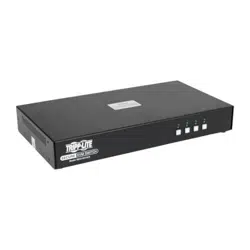
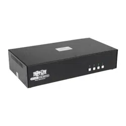
• NetDirector B030-Series Rack-Mount Console KVM Switch with IP Access
• (x2) High-Speed HDMI Cables - 6 ft., or (x2) DisplayPort Cables - 6 ft. (depending on model purchased)
• (x2) USB 2.0 A/B Cables – 6 ft.
• IEC C13 to NEMA 5-15P Power Cord
• Grounding Wire
• Quick Start Guide
• CD with Owner’s Manual
Check to ensure all components are present and in good order. If anything is missing, or was damaged in shipping, contact your dealer.
Read this manual thoroughly and follow the installation and operation procedures carefully to prevent any damage to the switch or to any other
devices on the installation.
Optional Accessories
• N201-Series Cat6 Gigabit Snagless Patch Cables
• P006-Series IEC C13 to NEMA 5-15P Power Cords
• P580-Series DisplayPort Cables with Latches (M/M)
• P569-Series High-Speed HDMI Cables, 4K, (M/M)
• P782-XXX-DH* HDMI/DVI + USB KVM Cable Kits (for model B030-008-17-IP only)
*XXX refers to the length, with cables available in 6 ft. (006), 10 ft. (010) and 15 ft. (015) lengths

5
4. Features
• Rack-Mount Console KVM Switch with built-in IP Access in a dual-rail housing with top and bottom clearance for integrated operation in 1U
of rack space.
• KVM console combines a 17.3” LCD monitor, keyboard, and touchpad.
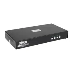
• Model B030-008-17-IP: connect an external DVI monitor or computer using HDMI to DVI adapter cables.
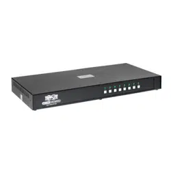
• Models B030-DP08-17DIP / B030-DP16-17DIP: connect an external DisplayPort monitor using DisplayPort cables.
• Multi-platform support; compatible with Windows
®
, Mac
®
, Linux
®
and Sun.
• Dual-Rail – LCD Monitor module can slide independently of the keyboard/touchpad module.
• A single console controls up to 8 or 16 computers.
• Remotely access computers via LAN, WAN, or the internet – control your installation when and where you want.
• 10/100/1000 network port.
• Grayscale option to improve transfer speed in low bandwidth situations.
• User-selectable network transfer rate.
• Optional external console ports located on the rear of the device – manage computers in the LCD KVM switch from an external console
(monitor, USB keyboard, USB mouse).
•
Features a USB 1.1 hub port on the front of the console for the connection of a USB peripheral device such as a flash drive or external mouse.
• Console lock – enables the console modules to remain securely locked away in position when not in use.
• Browser-based User Interface supported
• Browser access can be disabled – AP Windows and Java Clients are available for non-browser IP access to the KVM.
• Graphical OSD and graphical toolbars for convenient, user-friendly operation.
• Up to 64 user accounts – up to 32 concurrent remote logins.
• Message board feature allows logged-in users to communicate with one another and a remote user to take exclusive control of the
KVM functions.
• Panel Array Mode – view all ports at the same time in a grid format.
• Broadcast Mode support – Keyboard commands can be broadcast to all available computers in the installation.
• Three user account types: Super Administrator, Administrator, and User.
• Supports SSL 128-bit data encryption and RSA 1024-bit certificates to secure user browser logins.
• Flexible encryption design allows users to choose any combination of 56-bit DES, 168-bit 3DES, 256-bit AES, 128-bit RC4, or Random for
independent KB/Mouse, video and virtual media data encryption.
• Remote authentication support: RADIUS, LDAP, LDAPS and MS Active Directory.
• Flash firmware upgradable over a network connection.
• Ports can be set to Exclusive, Occupy and Share.
• Network Interfaces: TCP/IP, HTTP, HTTPS, UDP, RADIUS, DHCP, SSL, ARP, DNS, 10Base-T/100Base-TX, Auto Sense, and Ping.
• Supports video resolutions up to 1920 x 1080 @ 60 Hz.
• DDC emulation – video settings of attached computers are automatically adjusted for optimal output to the monitor.
• HDCP support (local monitor and external console port only).
• Includes an advanced FPGA graphics processor for improved video quality.
• UltraSync for USB mice ensures local and remote mouse movement are the same, eliminating the need to constantly re-sync the two
movements.
• Both IPv4 and IPv6 are supported.
• BIOS level access.
• Includes Automated Certificate Signing Request (CSR) creation utility and third party CA certificate authentication.
• Multi-language support; remote onscreen diagnostics can be displayed in English, Spanish, French, German, Russian, Italian, Japanese,
Korean, traditional Chinese and simplified Chinese.
• Remote access interface on-screen keyboard offers multi-language support.
• Supports exit Macros.
• Windows-based log server.
6
5. System Requirements
5.1 Built-in LCD Console
The integrated LCD monitor’s maximum resolution is 1920 x 1080 @60 Hz. Ensure all resolution settings of the connected computers do not
exceed the LCD monitor’s maximum resolution.
5.2 Optional External Console
• Model B030-008-17-IP: A DVI (user-supplied adapter required) or HDMI monitor capable of displaying the highest resolutions provided by
any computer in the installation.
• Models B030-DPXX-17DIP: A DisplayPort monitor capable of displaying the highest resolutions provided by any computer in the installation.
• USB keyboard and mouse.
5.3 Computers
The following equipment must be installed on each computer:
• A DVI, HDMI or DisplayPort video graphics card.
• USB mouse and keyboard ports.
5.4 Operating Systems
OS Supported Versions
Windows NT and higher
Mac OS 9.0 and higher
Linux RedHat 9.0 and higher
Linux SuSE 10 and higher
Linux Mandriva (Mandrake) 9.0 and higher
UNIX AIX 4.3 and higher
UNIX FreeBSD 5.5 and higher
UNIX Sun Solaris 8 and higher
Novell Netware 5.0 and higher
DOS 6.2 and higher
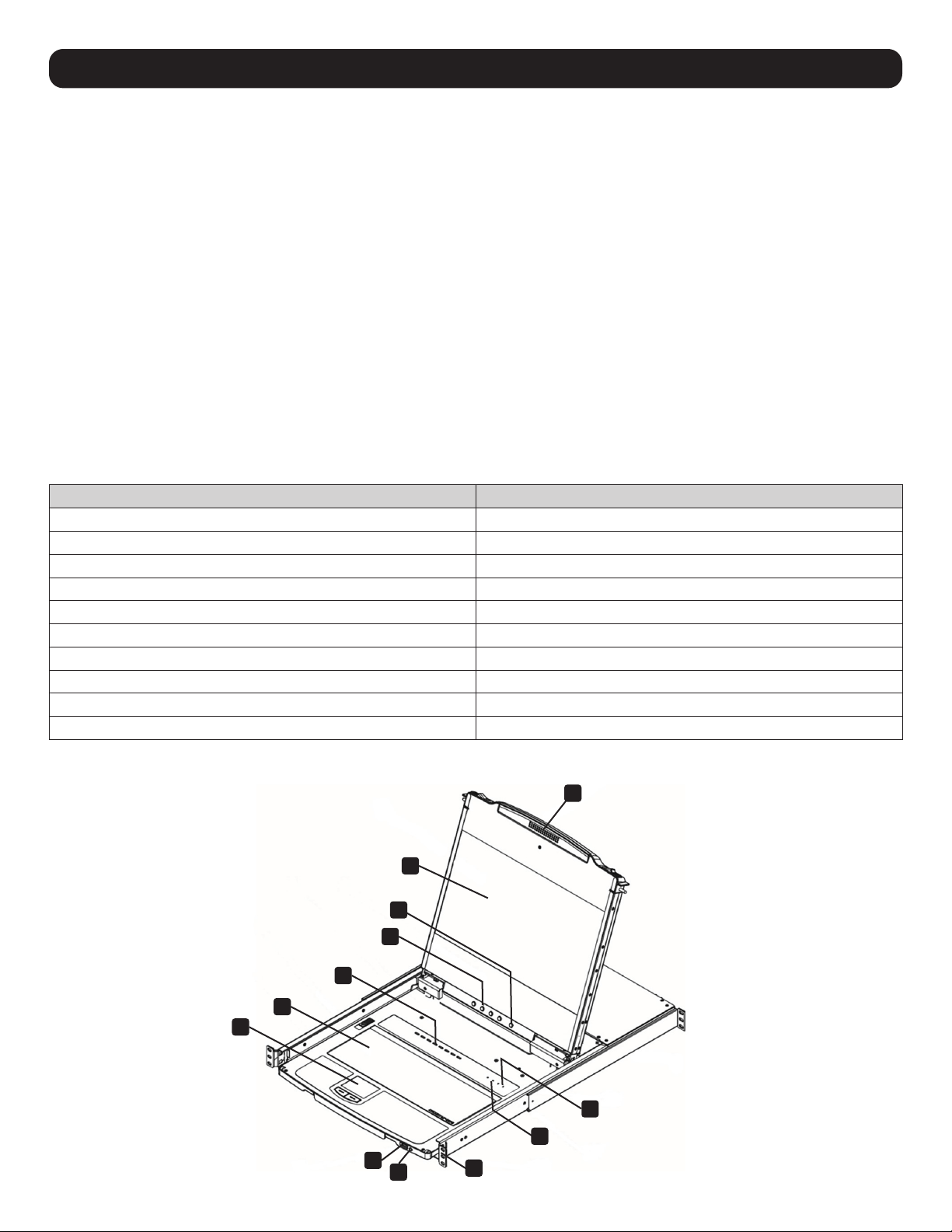
5.5 Components
Front View
1
3
5
2
6
7
8
9
10
11
12
4
7
5. System Requirements
No. Component Description
1
Handle Pull to slide the KVM module out; push to slide it in.
2
LCD Module After sliding out the KVM module, flip up the cover to access the LCD monitor.
3
LCD Controls The buttons to control the position and picture settings of the LCD monitor are located here.
4
LCD On / Off Button Push this button to turn the LCD monitor on and off. The button illuminates when the LCD monitor is off.
Note: The light indicates that only the monitor is off, not the attached KVM switch.
5
Port Selection
Buttons and LED
To access a port, press its corresponding selection button. Indicator LEDs are built into the switches, with an
Online LED to indicate that the computer attached to its corresponding port is up and running, and a Selection
LED light to indicate which port has the KVM focus.
• Press buttons 1 and 2 at the same time for 5 seconds to perform a keyboard/mouse reset.
• Press buttons 7 and 8 at the same time for 2 seconds to initiate an Auto Scan.
6
Keyboard Module Standard 99-key keyboard.
7
Touchpad Standard mouse touchpad.
8
USB Port The USB 1.1 hub port connects a USB peripheral device (flash drive, CD-ROM drive, etc.) to the console or a
USB mouse for users who prefer to use an external mouse.
9
Power LED Illuminates blue to indicate the device is receiving power.
10
Rack Mounting Tabs Rack mounting tabs are located at each corner of the device.
11
Lock LEDs The Num Lock, Caps Lock, Scroll Lock LEDs are located here.
12
Reset Switch
Located to the right of the Lock LEDs. Press this recessed switch using a thin object to perform a system reset.
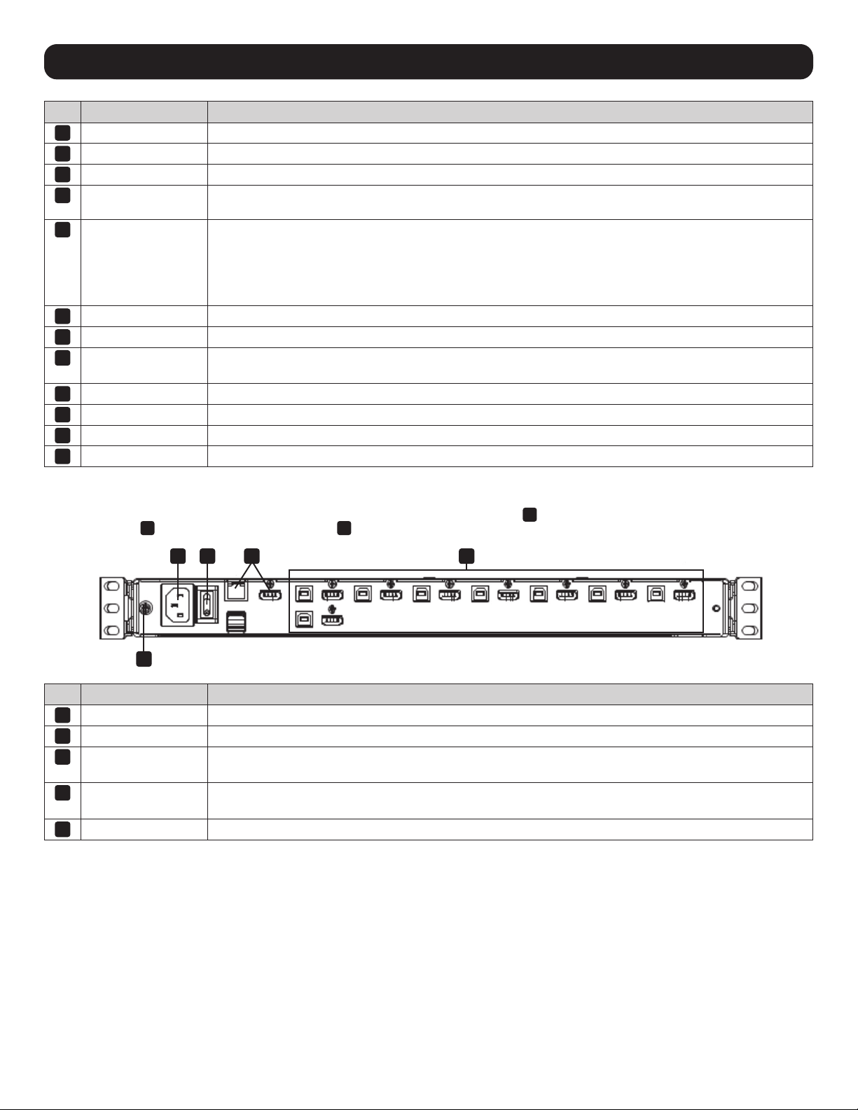
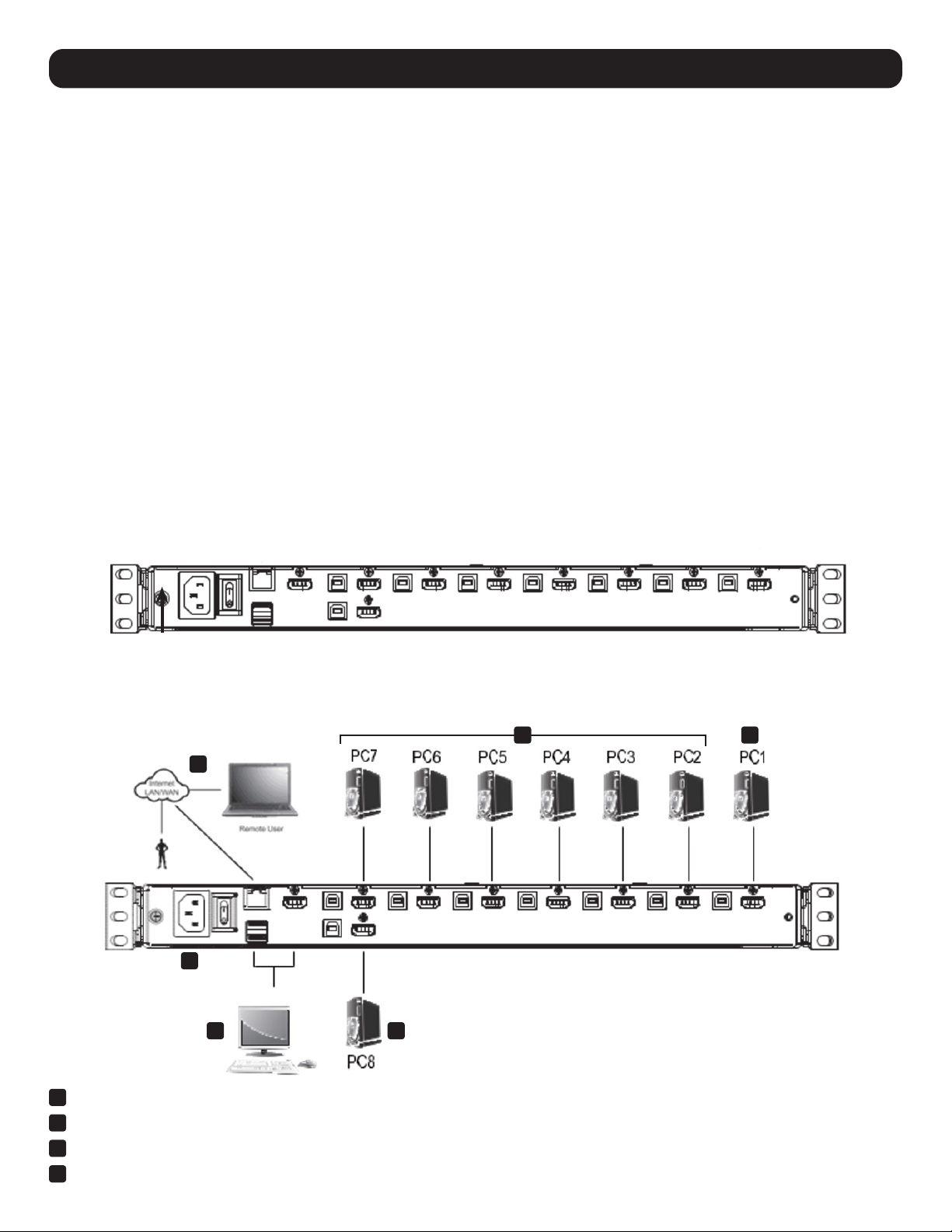
Rear View
Note: B030-008-17-IP is shown below. B030-DP08-17DIP is identical, except the video input port
3
is DisplayPort. B030-DP16-17DIP is identical, except
the video input port
3
is DisplayPort and there are 16 ports
4
.
No. Component Description
1
Power Socket This is a standard 3 prong C14 AC power connector. The power cord from an AC source plugs in here.
2
Power Switch This is a standard rocker switch that powers the device on and off.
3
External Console
Section
Supports an independent, external KVM console for flexibility and convenience. The external console's USB
keyboard and mouse, monitor and audio cables plug in here.
4
KVM Port Section
Connects the device’s ports to computers/servers using HDMI/DisplayPort and USB cables. (see Optional
Accessories in section 3 for the KVM cable kit model)
5
Grounding Terminal The included grounding wire attaches here.
1
5
2 3 4

8
6. Important Safety Instructions
6.1 General Safety Instructions
• Read all of these instructions and save them for future reference.
• Follow all warnings and instructions marked on the device.
• Do not place the device on any unstable surface. If the device falls, serious damage will result.
• Do not use the device near water.
• Do not place the device near or over, radiators or heat registers.
• The device cabinet is provided with slots and openings to allow for adequate ventilation. To ensure reliable operation and protect against
overheating, these openings should never be blocked or covered.
• The device should never be placed on a soft surface such as a bed, sofa of rug. Doing so will block the device’s ventilation openings.
Moreover, the device should not be placed in a built-in enclosure unless adequate ventilation has been provided.
• Never spill liquid of any type on the device.
• Unplug the device from the wall outlet before cleaning. Use a damp cloth for cleaning. Do not use liquid or aerosol cleaners.
• The device should be operated from the power source indicated on the marking label. If uncertain of the power available, consult your dealer
or local power company.
• The device is designed for IT power distribution systems up to 230V phase-to-phase voltage.
• As an added safety feature, the device is equipped with a 3-wire grounding type plug. If unable to insert the plug into the outlet, contact
an electrician to replace the obsolete outlet. Do not attempt to plug into a two-prong ungrounded outlet. Always follow local/national wiring
codes.
• Do not allow anything to rest on the power cord or cables. Route the power cord and cables to avoid them being stepped on or tripped over.
• If an extension cord is used with this device, ensure the total ampere ratings of all products used on the extension cord do not exceed its
rated ampere rating. Also ensure all products plugged into the wall outlet does not exceed a total of 15 amperes.
• Consideration should be given to the connection of equipment and the supply circuit, as well as what effect overloading the supply circuit
might have on overcurrent protection and supply wiring.
• To help protect the system from unexpected transient increases and decreases in electrical power, use a Tripp Lite Surge Protector, Line
Conditioner, or Uninterruptible Power Supply (UPS).
• Position system cables and power cables carefully so nothing rests on any cables.
• When connecting or disconnecting power to hot pluggable power supplies, observe the following guidelines:
– Install the power supply before connecting the power cable to the power supply.
– Unplug the power cable before removing the power supply.
– If the system has multiple sources of power, disconnect power from the system by unplugging all power cables from the power supplies.
• Never push objects of any kind into or through cabinet slots. They may touch dangerous voltage points or short out parts resulting in a risk of
fire or electrical shock.
• Do not attempt to service the device; refer all servicing to qualified service personnel.
• If the following conditions occur, unplug the device from the wall outlet and bring it to qualified service personnel for repair:
– The power cord or plug has become damaged or frayed.
– Liquid has been spilled into the device.
– The device has been exposed to rain or water.
– The device has been dropped, or the cabinet has been damaged.
– The device exhibits a distinct change in performance, indicating a need for service.
– The device does not operate normally when the operating instructions are followed.
• Only adjust controls covered in the operating instructions. Improper adjustment of other controls may result in damage that will require
extensive work by a qualified technician to repair.
• Use of this equipment in life support applications where failure of this equipment can reasonably be expected to cause the failure of the life
support equipment or to significantly affect its safety or effectiveness is not recommended. Do not use this equipment in the presence of a
flammable anesthetic mixture with air, oxygen or nitrous oxide.

9
6. Important Safety Instructions
6.2 Rack-Mounting Safety Instructions
• The ambient operating temperature in the rack may be an issue and is dependent upon the rack load and ventilation. When installing in a
closed or multi-device rack assembly, ensure the temperature will not exceed the maximum rated ambient temperature.
• Before installing the rack, ensure the stabilizers are secured to the rack, extended to the floor and the full weight of the rack rests on the
floor. Install front and side stabilizers on a single rack or front stabilizers for joined multiple racks before working on the rack.
• Always load the rack from the bottom up with the heaviest item loaded into the rack first.
• When loading the rack, avoid creating a hazardous condition due to uneven loading.
• Ensure the rack is level and stable before extending a device from the rack.
• Use caution when pressing the rail release latches or sliding a device into or out of a rack; slide rails can pinch your fingers.
• After a device is inserted into the rack, carefully extend the rail into a locking position, then slide the device into the rack.
• Do not overload the AC supply branch circuit that provides power to the rack. The total rack load should not exceed 80 percent of the branch
circuit rating.
• Ensure that proper airflow is provided to devices in the rack.
• Do not step on or stand on any device when servicing other devices in a rack.
• Do not connect the RJ11 connector marked “Upgrade” to a public telecommunication network.
• Caution! Slide/Rail (LCD KVM) mounted equipment is not to be used as a shelf or work space.
10
7. Installation
The Console KVM Switch is designed for mounting in a 1U rack system. A rack-mounting kit is included for quick installation. The various
mounting options are explained in the following subsections. The installation instructions depict model B030-008-17-IP, but all steps are the
same for all models.
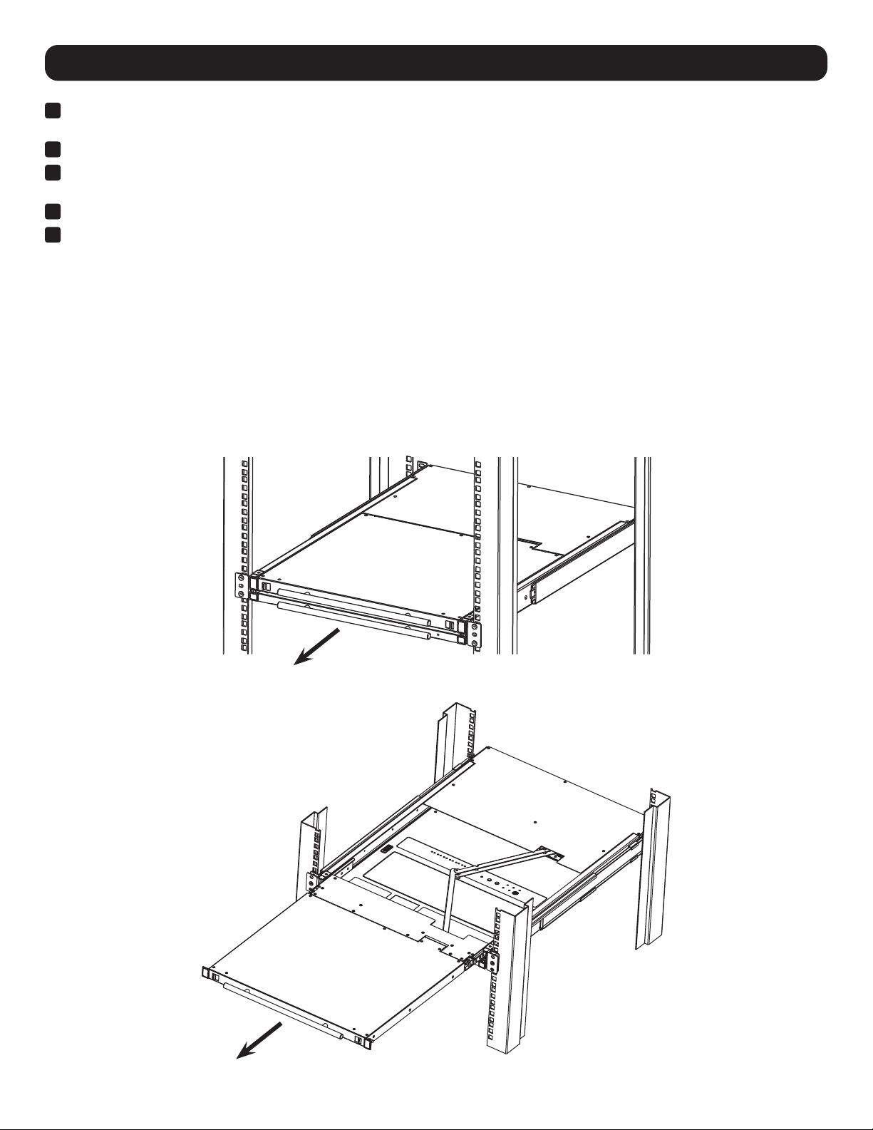
7.1 Standard Rack Mounting
The standard rack mounting brackets that come attached to the console KVM switch allow the device to be installed in a standard 1U rack by
a single individual.
1. Slide out the rear mounting brackets from the console and mount both brackets (separate from the console) to the inside rear of a
standard 1U rack system using user-supplied screws.
2. Gently slide the console into the two rear-mounted brackets in the rack and secure the console in place with user-supplied screws.
7.2 2-Post Rack Mounting
The console KVM switch can also be mounted in a 2-post rack installation using the optional 2-Post Rack Mount Kit (model #: B019-000).
The mounting hardware allows for the console to be opened with the drawer in any position. Heavy-duty 14-gauge steel provides stability and
prevents the console frame from twisting. See the B019-000 instructional manual for detailed mounting instructions.
7.3 Grounding
To prevent damage to the installation, it is important that all devices are properly grounded. Use the included green-yellow ground wire
(min. 0.5 mm
2
, min. 20 AWG) to ground the KVM switch by connecting one end of the wire to the grounding terminal on the device and the
other end of the wire to a suitable grounded cabinet.
7.4 KVM Switch Installation
To set up the console KVM switch, refer to the following steps and installation diagram.
1
Power off all computers that will connect to the KVM switch.
2
Connect a USB cable from a USB CPU port on the KVM to the USB port on a computer.
3
Connect the HDMI CPU port on the KVM to the HDMI or DVI* port on a computer.
4
Repeat steps 2 and 3 for each additional computer you are connecting to the KVM.
34
6
7
5 4
11
7. Installation
5
(Optional) Add an external console to the KVM by connecting an HDMI or DVI* monitor and USB keyboard and mouse to the console ports
on the back of the device.
6
Connect the LAN port on the back of the device to the network using Cat5e/6 cable.
7
Plug the included power cord into a Tripp Lite Surge Protector, Power Distribution Device (PDU), Uninterruptible Power Supply (UPS) or AC
wall outlet.
8
Power the connected computers.
9
Power the KVM device.
*Using an HDMI to DVI adapter cable, such as Tripp Lite’s P566-Series cables.
7.5 Opening / Closing the Console
The console consists of two modules: an LCD module located under the top cover and a keyboard / touchpad module below the LCD module.
The modules can slide together or independently of one another. This allows the LCD to be available for viewing while the keyboard / touchpad
module is not in use.
7.5.1 Opening Separately
1. Release the console by sliding the front panel toward the center. Then engage the catches and pull the top panel 1-2 inches toward you.
Once the console has been released, release the catches.
2. Pull the top panel all the way out until it clicks into place.
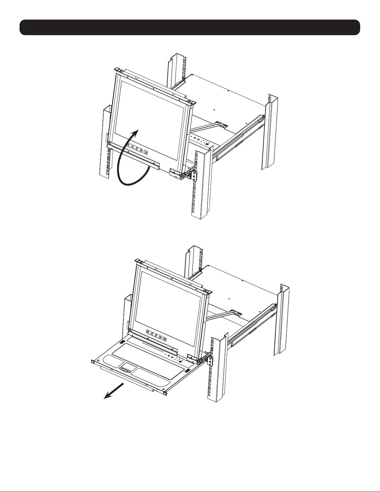
12
3. Rotate the top panel all the way back to expose the LCD screen.
4. Reach underneath and pull out the keyboard module until it clicks into place.
7.5.2 Opening Together
Refer to the diagrams in the Opening Separately section as you do the following:
1. Engage the release catches and pull the top and bottom panels out until the keyboard module clicks into place. Once the console has been
released, release the catches.
2. Pull the top panel out until it clicks into place.
3. Rotate the top panel all the way back to expose the LCD screen.
7. Installation
13
7. Installation
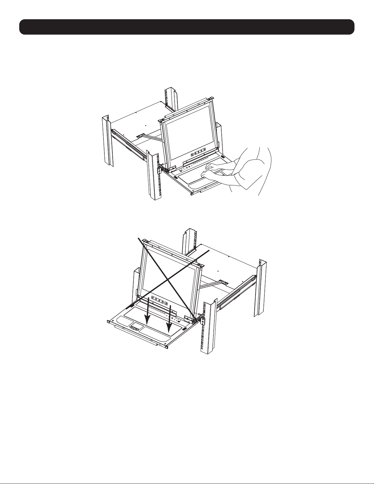
7.5.3 Opening Precautions
The maximum load bearing capacity of the keyboard module is 65 lb. Failure to heed the instructions below can result in damage to the
keyboard module.
CORRECT
Rest your hands and arms lightly on the keyboard module as you work.
INCORRECT!
• DO NOT apply body weight on the keyboard module.
• DO NOT place heavy objects on the keyboard module.
14
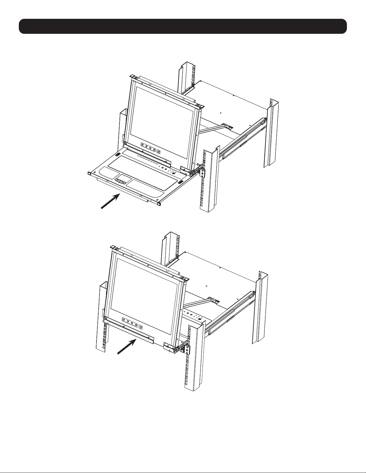
7.5.4 Closing the Console
1. Engage the release catches located on either side of the keyboard to release the keyboard module, then slide in the module slightly.
2. Release the catches. Using the front handle, push the keyboard module all the way in.
7. Installation

15
7. Installation
3. Rotate the LCD module all the way down, then engage the rear catches to release the LCD module.
4. Using the front handle, push the module all the way in.
16
7. Installation
7.6 Network Setup – IP Address Configuration
By default, the KVM will automatically have an IP address assigned via DHCP server. To configure a fixed IP address, you will need to access
the KVM switch in one of three ways: Local Console, IP Installer or Browser.
7.6.1 Local Console
Note: The local console OSD only allows IPv4 network settings configuration. For IPv6, access the Web Management Interface.
1. When accessing the console KVM switch for the first time, a prompt will appear asking for a username and password. The default
Username is administrator, and the default Password is password. For security purposes, changing the username and password is
strongly recommended. Once the default username and password are entered, the OSD Main page will appear.
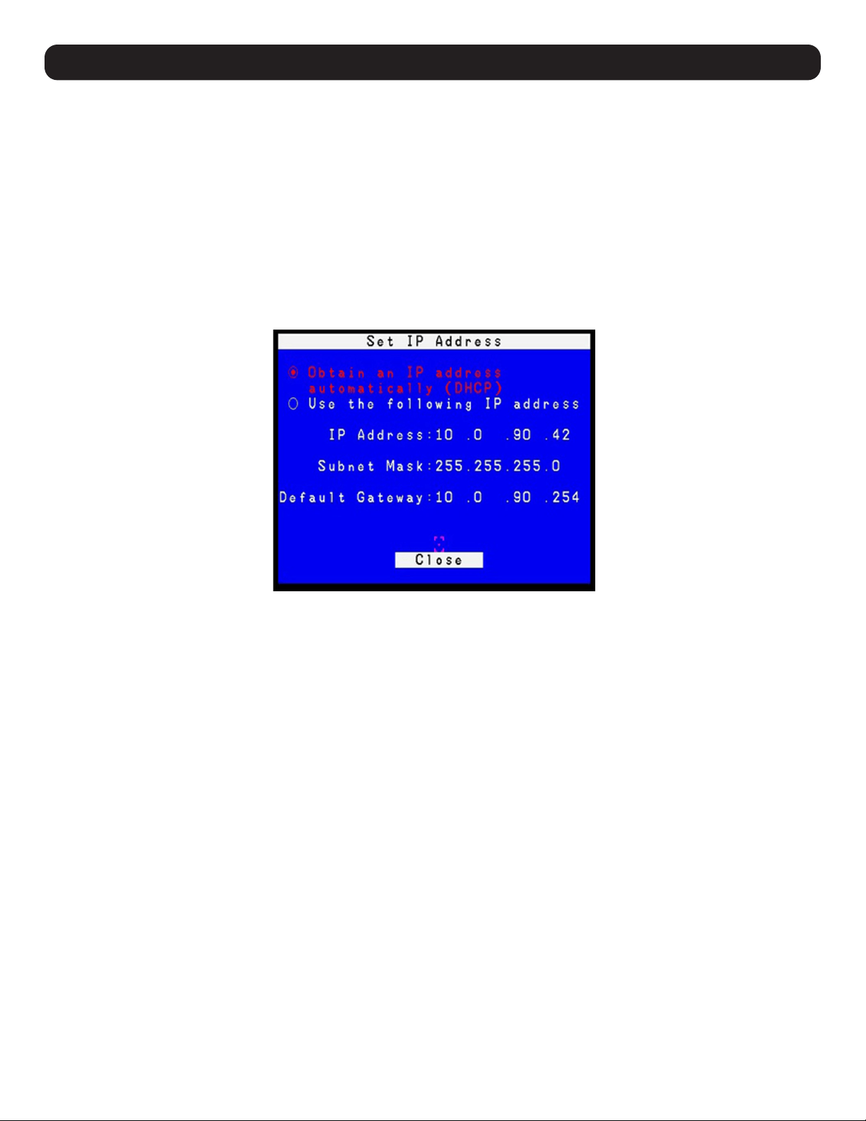
2. Press the [F4] key to open the OSD ADM page.
3. In the OSD ADM page, highlight SET IP ADDRESS and press [Enter]. The following screen appears.
4. By default, the Obtain an IP address automatically (DHCP) option is selected. To manually assign an IP address, check the radio button next
to the Use the following IP address option.
5. You can then navigate to the IP Address, Subnet Mask and Default Gateway fields by entering the settings suitable for your network. Upon
changing the KVM’s IP Address settings, the Reset on Exit function of the F4: ADM menu will be automatically activated. Upon logging
out, the new settings will be saved for use going forward. If you go into the F4: ADM menu and clear the Reset on Exit check mark before
logging out, the changed settings will be ignored and the original IP Address settings will remain in effect.
Note: Although the changed IP settings are ignored, they still remain in the network settings fields. The next time a page is opened, the Reset on Exit box
will automatically be enabled. When the switch resets, the new IP settings will become the ones used by the switch. To avoid this problem, go back to the
network settings page and ensure the desired IP settings appear in the fields.
17
7. Installation
7.6.2 IP Installer
Computers running Windows can use the IP Installer utility found in the included CD-ROM to assign an IP address to the KVM.
Notes:
• The IP Installer Settings section located in the KVM’s Web Management Interface network page must be enabled in order to use the IP Installer to assign an
IP address. This setting is enabled by default.
• The local console OSD only configures IPv4 network settings. For IPv6, access the Web Management Interface.
1. Save the IP Installer.exe file from the CD to a desired location on a computer that is on the same network as the KVM switch.
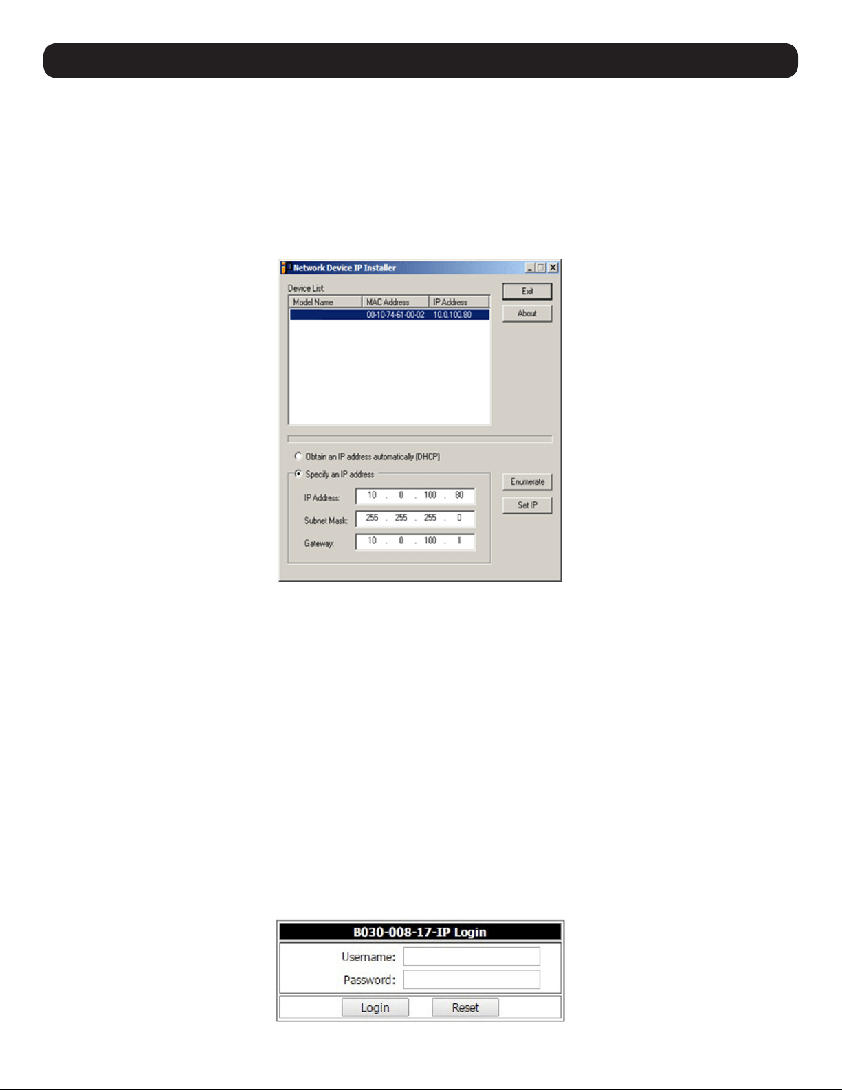
2. Locate the recently saved IP Installer.exe file and double-click on its icon. A screen similar to the one below will appear.
3. The IP Installer searches the network and displays all B030-008-17-IP switches found in the device list. If your device does not appear in
the list, click the Enumerate button to refresh the device list. If more than one of the same KVM switch models appears in the list, locate
the desired device using the MAC address found on the bottom of the console KVM. Once your device is located in the list, highlight it.
4. From here you can choose between the following two options: 1. Obtain an IP address automatically (DHCP), or 2. Specify an IP address.
If you choose to assign your own address, fill in the IP Address, Subnet Mask, and Gateway fields with information appropriate to your
network. Click on the Set IP button to apply the new network settings to the selected KVM switch.
5. After the new IP address shows up in the device list, click the Exit button to exit the IP Installer.
7.6.3 Browser
By default, the KVM switch will have an IP Address automatically assigned via DHCP server. If the KVM Switch is on a network that does not
have a DHCP server to automatically assign an IP address, it boots with a default IP address. The default IPv4 and IPv6 addresses can be
found on the sticker located on the bottom of the KVM.
1. For a computer/server on the same network as your console KVM switch, set the computer/server’s IP address to 192.168.0.XXX, where
XXX represents any number or numbers except the KVM’s default address.
2. Using this computer/server, access the KVM switch via the default address. A screen will appear asking to provide a username and
password.
Note: If first prompted by a screen stating the website’s security certificate cannot be trusted, click on the link to proceed anyway; the certificate can be
trusted.
18
3. If accessing the KVM for the first time, enter the username administrator and the password password. For security purposes, changing
the username and password is strongly recommended. Once the default username and password are entered, the web management
interface will appear with the following page displayed:
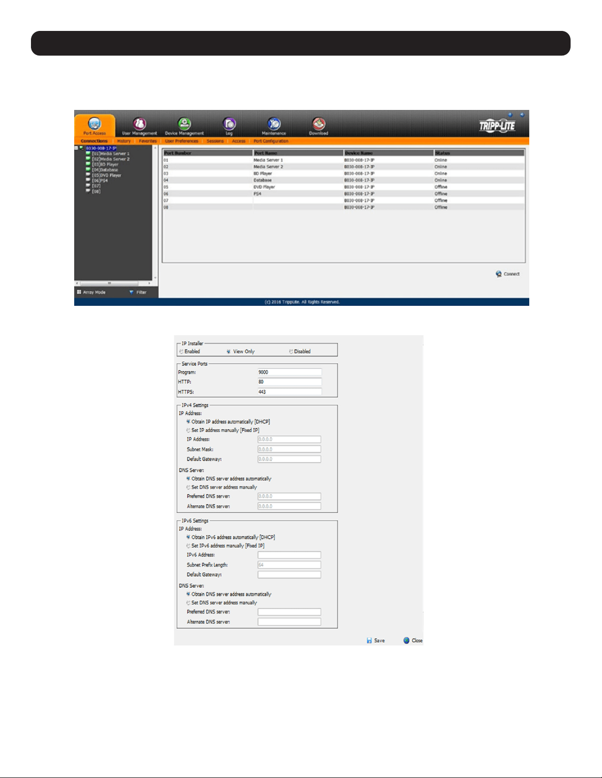
4. Click on the Device Management icon at the top of the page, then click on the Network tab. The Network page will appear.
5. The KVM switch supports both IPv4 and IPv6 addresses. The Network page can set the IP address manually or be automatically assigned
via DHCP server. By default, the IP address is set to be automatically assigned via DHCP server. To manually assign an IP address, check
the Set IP address manually check box in the IPv4 Settings or IPv6 Settings sections, depending on your network.
6. When checked, the IP address and DNS server address fields open up. Enter the desired settings in the fields. Once all IP address and DNS
server address information is entered, click the Save icon at the bottom of the screen. Upon logging out of the KVM (click the Logout icon
in the upper-right corner of the screen), the KVM will reset itself and the IP address settings just entered will be implemented.
7. Installation
19
8. Basic Operation
8.1 LCD OSD Configuration
8.1.1 LCD Buttons
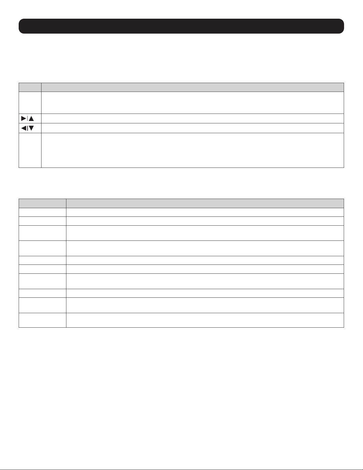
The LCD OSD configures the LCD. Four buttons are used to perform the configuration, as described in the table below:
Button Function
MENU • When the LCD OSD Menu function has not been entered, pressing this button initiates the Menu function and the Main Menu.
• When the LCD OSD Menu function has been entered and has reached a setting choice with the navigation buttons, pressing this
button initiates the adjustment screen.
When navigating through the menus, this button moves the page right or up. When making an adjustment, it increases the value.
When navigating through the menus, this button moves the page left or down. When making an adjustment, it decreases the value.
EXIT • When the LCD OSD Menu function has not been entered, pressing this button performs an auto adjustment. An auto adjustment
automatically configures all the settings for the LCD to what the OSD considers their optimum values to be.
• When you have entered the LCD OSD Menu function, pressing this button exits the current menu and returns you to the previous
menu. Use it to leave an adjustment menu when you are satisfied with the adjustments.
• When at the Main Menu, pressing this button exits the LCD OSD.
8.1.2 Adjustment Settings
LED OSD adjustment settings are described in the table below:
Setting Explanation
Brightness Adjusts the background black level of the screen image.
Contrast Adjusts the foreground white level of the screen image.
Phase If pixel jitter or horizontal line noise is visible on the display, the LCD may have the wrong phase setting. Adjust the
phase setting to eliminate these problems.
Clock If vertical banding is visible on the display, the LCD may have the wrong clock setting. Adjust the clock setting to
eliminate vertical banding.
H-Position Positions the display area on the LCD panel horizontally (moves the display area left or right).
V-Position Positions the display area on the LCD panel vertically (moves the display area up or down).
Color Temperature Adjusts the color quality of the display, such as the warmth value and color balance. The Adjust Color selection contains
a submenu to fine tune RGB values.
Language Selects the OSD display menus’ language.
OSD Duration Sets the amount of time the OSD will display on the screen. If there is no input for the amount of time chosen, the OSD
display turns off.
Reset Resets the adjustments on all menus and submenus to factory default settings.
Note: The Language setting does not return to the factory default, but remains at the one it is currently set to.
8.1.3 Hot Plugging
The Console KVM Switch supports hot plugging – components can be removed and added to the computer by unplugging their cables from the
ports without the need to shut down the KVM.
8.1.4 Powering Off and Restarting
If it becomes necessary to power off the KVM switch, or if the switch loses power and needs to be restarted, wait 10 seconds before powering
it back on. The computers should not be affected by this, but should any of them should fail, simply restart the affected computers.
8.1.5 USB Peripheral Devices
The USB 1.1 port on the keyboard module’s front panel can connect a USB peripheral device, such as a flash drive, CD-ROM drive or printer.
Any computer connected to the device can access the USB peripheral on a one-by-one basis. When switching from one computer to another,
the peripheral device automatically disconnects from the original computer and connects to the newly selected computer.
Note: When connecting a flash drive or other type of external storage device, always eject the device prior to switching ports.
20
9. KVM Operation
9.1 Local Console
9.1.1 Local Console Login
When accessing the console KVM switch for the first time, a prompt will appear asking for a username and password. The default username
is administrator, and the default password is password. For security purposes, changing the username and password on this account is
strongly recommended. Once the KVM has been set up and user accounts have been created, the login prompt will appear only when a
user logs out of the KVM. After logging in for the first time using the default username and password, the OSD Main Screen will appear in
Administrator mode with access to all settings and functions.
9.1.2 Local Console OSD Hotkey Sequence
Once logged into the KVM switch and a connected computer, use the local console OSD Hotkey sequence to re-open the OSD Main Menu.
The default hotkey sequence is [Scroll Lock, Scroll Lock], but other options include [Ctrl, Ctrl], [Alt] [Alt], [Shift] [Shift] or [Print Screen]
[Print Screen].
Note: When using the [Scroll Lock, Scroll Lock] OSD Hotkey sequence, hold down the [Fn] key, as the [Scroll Lock] key is part of the [Num Lock] key.
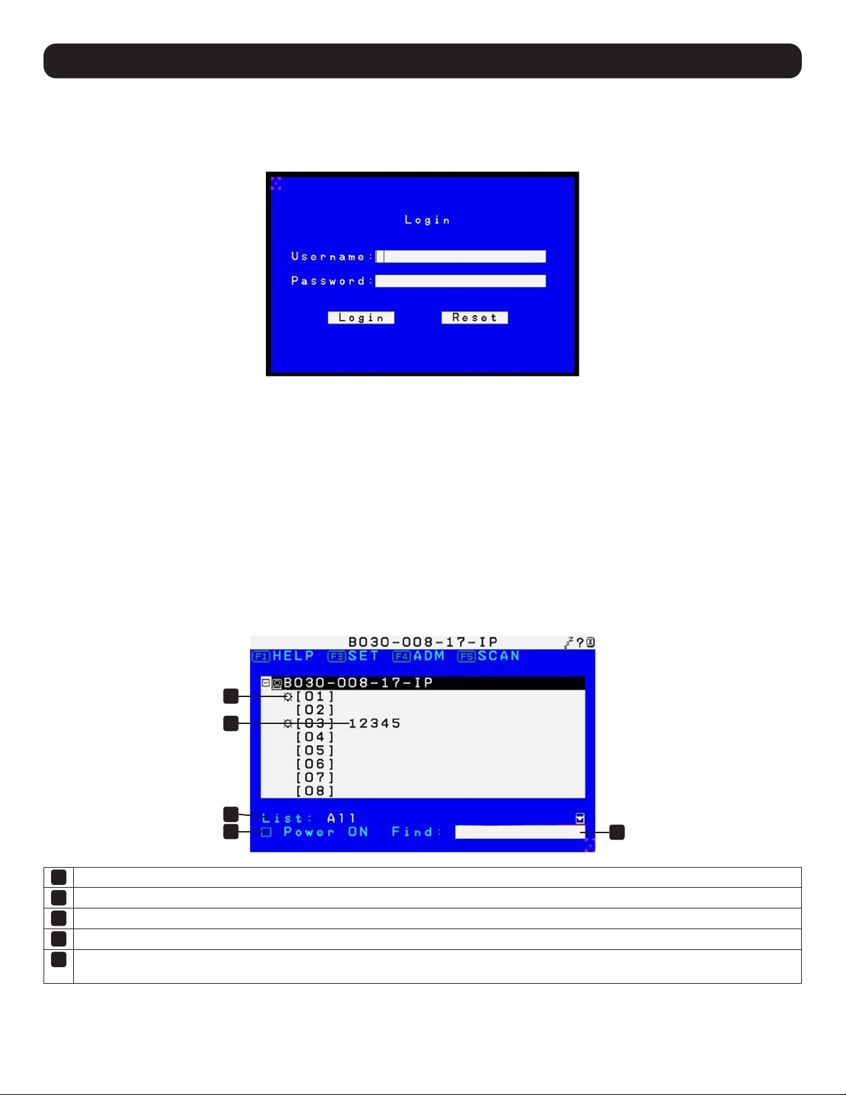
9.1.3 OSD Main Menu
1
Connected computers that are powered on and online have a sun symbol in this column.
2
If a port has been given a name, it appears in this column.
3
Click the Power ON box to display only the port information of computers that are both powered on and online.
4
In the Find field, key in the name of a port that you want to find.
5
In the List field, choose to display All computers in the installation or only your Favorites list.
Note: The default is All.
1
3
4
5
2
21
9. KVM Operation
9.1.4 OSD Navigation
• To dismiss the menu and deactivate the OSD, click the X in the upper right corner of the OSD window or press [Esc].
• To log out, click the ZZZ icon in the upper right corner of the main screen or press [F8].
• To move up or down through the list one line at a time, click the up and down triangle symbols or use the up and down arrow keys. If there
are more list entries than appear on the main screen, the screen will scroll.
• To access the computer connected to a port, double-click or move the highlight bar to its location, then press [Enter].
• After executing any action, the cursor will automatically return to the menu one level above.
9.1.5 OSD Functions
OSD functions are used to configure and control the OSD. Examples include: rapidly switching to any port, creating a favorites list, creating or
editing a port name, or making OSD settings adjustments.
To access an OSD function:
1. Click a function key field at the top of the main screen or press a function key on the keyboard.
2. In the submenus, either double-click or move the highlight bar to its location, then press [Enter].
3. Press [Esc] to return to the previous menu level.
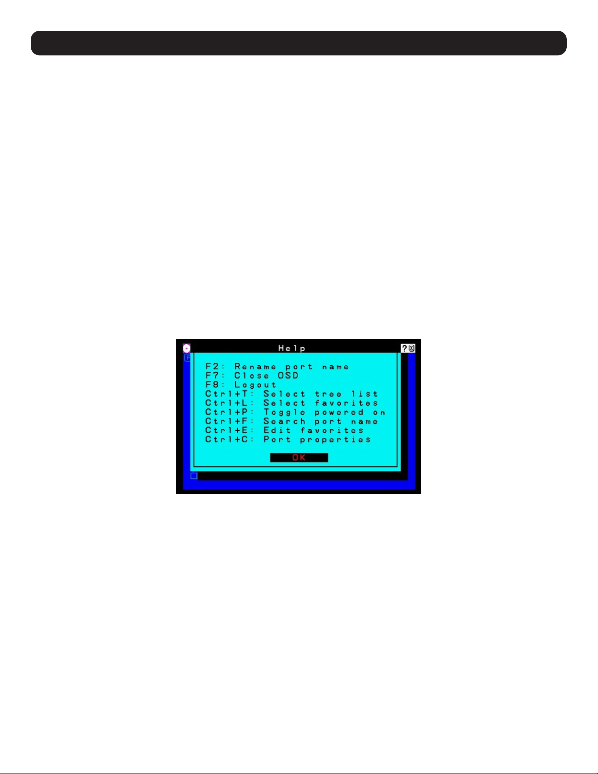
F1: Help
The only function keys visible on the OSD Main Screen are [F1], [F3], [F4], and [F5]. Using the [F1] HELP function will show other available
function keys: [F2], F7], [F8], [Ctrl]+[T], [Ctrl]+[L], [Ctrl]+[P], [Ctrl]+[F], [Ctrl]+[E], [Ctrl]+[C].
F2: Rename Ports Name
To help remember which computer is connected to a particular port, every port can be given a name. This function allows the administrator to
create, modify, or delete port names. To edit a port name:
1. Click a port in the list on the OSD Main screen or use the navigation keys to move the highlight bar to its location, then press [F2].
2. Key in the new port name or modify/delete the old one. The maximum number of characters allowed for the port name is 12. Case does
not matter; OSD displays the port name in all capitals, no matter how they were keyed in. Legal characters include:
• All alpha characters: A–Z
• All numeric characters: 0–9
• * ( ) + : - , ? . / and [Space]
3. When finished editing, press [Enter] for the change to take effect. To abort the change, press [Esc].
22
9. KVM Operation
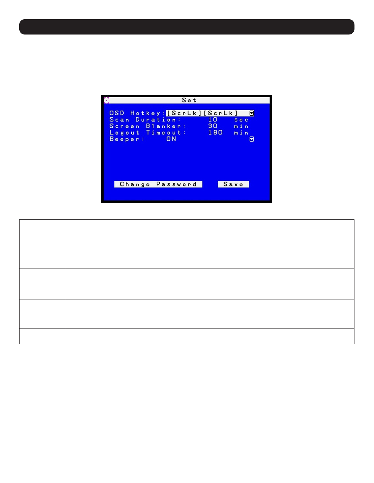
F3: Set
This function allows the administrator and users to set up their own working environments. A separate profile for each client is stored by the
OSD and activated according to the username provided during login. To change a setting:
1. Double-click or move the highlight bar to its location, then press [Enter].
2. After selecting an item, a submenu with additional choices will appear. To make a selection, double-click or move the highlight bar to its
location, then press [Enter]. An icon will appear before the selected choice.
The settings are explained in the following table:
OSD Hotkey The default setting is [Scroll Lock] [Scroll Lock]. The OSD hotkey can be changed to any of the following combination
commands:
• [Scroll Lock] [Scroll Lock]
• [Ctrl] [Ctrl]
• [Alt] [Alt]
• [Shift] [Shift]
• [Print Screen] [Print Screen]
Scan Duration Determines how long each port cycles through the selected ports in Auto Scan mode. Key in a value from
1–255 seconds, then press [Enter]. Default is 5 seconds; a setting of 0 disables the SCAN function.
Screen Blanker If there is no input from the console for the amount of time set here, the screen is blanked. Key in a value from
1–30 minutes, then press [Enter]. The default setting of 0 minutes disables this function.
Logout Timeout If there is no input from the console for the amount of time set here, the user is automatically logged out. A login is
necessary before the console can be accessed again. This enables other users to gain access to the OSD when the
original user is no longer accessing them and has forgotten to logout. To set the timeout value, key in a number from
0–180 minutes, then press [Enter]. A setting of 0 disables the Logout Timeout. The default setting is 30 minutes.
Beeper Options are ON or OFF. When activated, the beeper sounds whenever a port is changed, when activating the Auto Scan
function, or when an invalid entry is made in the OSD menu. The default is ON.
23
9. KVM Operation
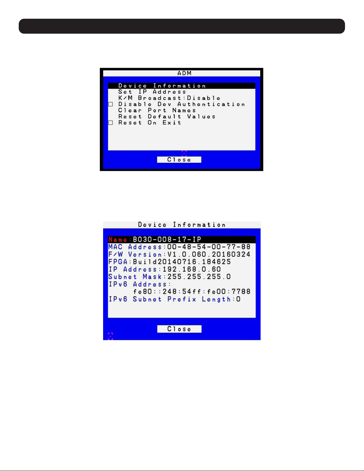
F4: ADM
F4 is an administrator-only function. It allows the administrator to configure and control the overall operation of the OSD. To change a setting,
double-click or move the highlight bar to its location, then press [Enter].
After selecting an item, a submenu with additional choices will appear. Double-click or move the highlight bar to its location, then press [Enter].
An icon will appear before the selected item.
Device Information
The Device Information page displays the name of the selected device, its firmware version, the FPGA (Field-Programmable-Gate-Array) and
information about its network configuration.
24
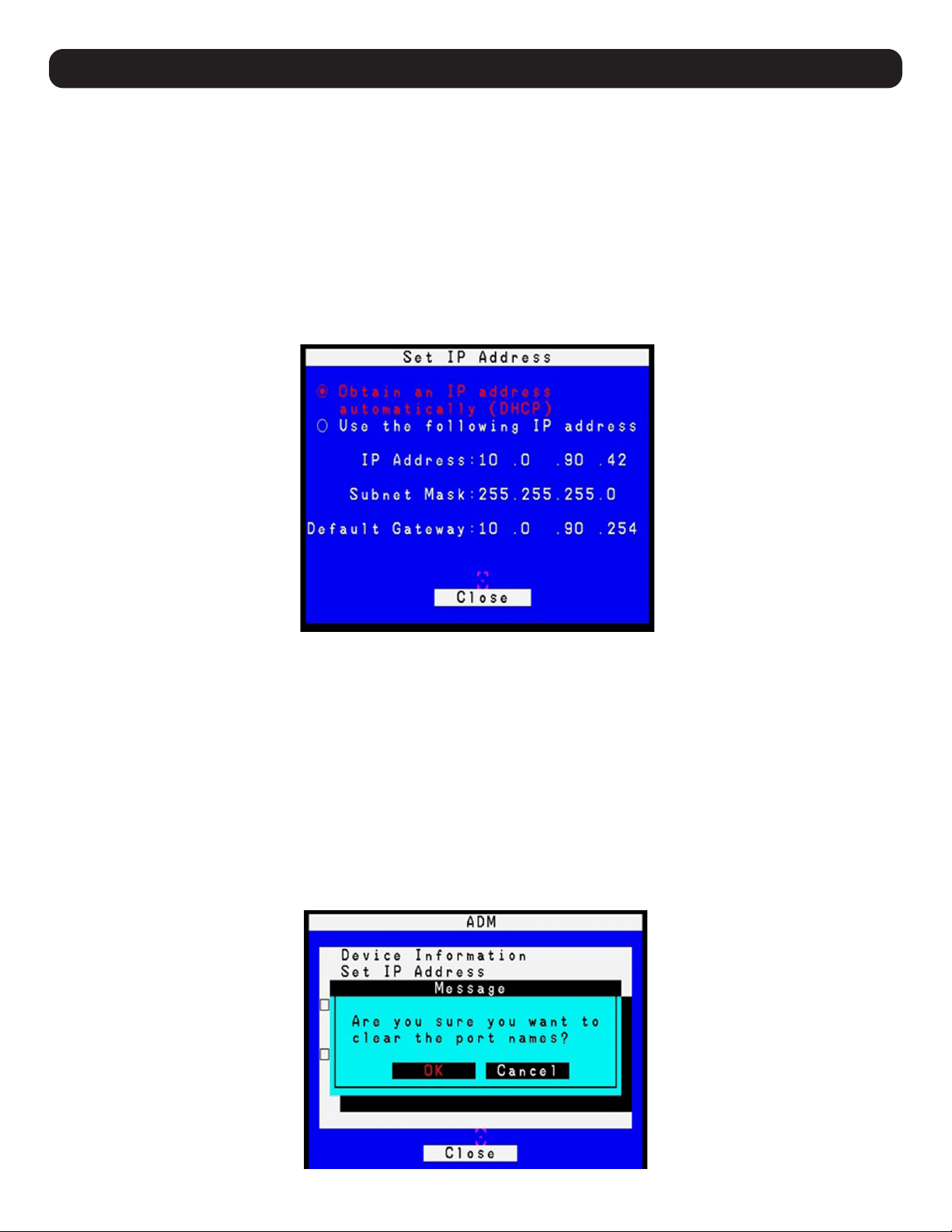
Set IP Address
The KVM can have an IP address assigned dynamically (DHCP) or be given a fixed IP address.
• Obtain an IP address automatically (DHCP) – This option is selected by default. If the Use the following IP address option is selected instead,
check the radio button next to the Obtain an IP address automatically (DHCP) option to switch.
• Use the following IP address – To manually configure the IP address, check the radio button next to the Use the following IP address option.
Then navigate to the IP Address, Subnet Mask and Default Gateway fields, and enter the settings suitable for your network. Upon changing
the IP Address settings of the KVM, the Reset on Exit function of the F4: ADM menu will be automatically activated. Upon logging out, the
new settings will be saved for future use. By going into the F4: ADM menu and clearing the Reset on Exit check mark before logging out, the
changed settings will be ignored and the original IP Address settings will remain in effect.
Note: Even though the changed IP settings are ignored, they still remain in the network settings fields. In effect, the next time this page is opened, the reset
on exit box will automatically be enabled. When the switch resets, the new IP settings that were discarded will be used by the switch. To avoid this problem, go
back to the network settings page to ensure the desired IP settings appear in the fields.
KM Broadcast
Keyboard and Mouse inputs can be sent to all of the connected computers at the same time. This can be useful in situations such as
performing a system-wide shutdown, installing or upgrading software, etc. This function is disabled by default.
• If you enable Keyboard Broadcast, your keystrokes will be sent to all connected computers that currently appear in the Sidebar.
• If you enable Mouse Broadcast, your mouse movements and clicks will be sent to all connected computers that currently appear in the
Sidebar.
Disable Dev Authentication
The function disables KVM access by all local user accounts. Users can only login using authentication via RADIUS, LDAP, LDAPS, or MS active
Directory.
Clear Port Names
Use this function to clear all port names.
9. KVM Operation

25
9. KVM Operation
Reset Default Values
Clicking this button undoes all Customization page changes that have been made to the B030-008-17-IP and returns the parameters to the
original factory default settings. The reset values include the following items:
• Security
– Mode: Enable ICMP, Enable Multiuser Operation, Enable Virtual Media Write Operation, Browser Service
– Login Failures: Allowed/ Timeout
• Network
– Network Transfer Rate reset to 99999
• Port Configuration
– Device Level: Occupy timeout setting
• Operating mode
– Force All to Grayscale, Enable Client AP device list, Keyboard/Mouse Broadcast, Console Keyboard language
• Port Level
– Port Properties: Port OS, Access Mode, OS language
Reset on Exit
The Reset on Exit function resets the KVM upon logout to save changes to the IP Address Settings page. When assigning new IP Address
settings, this function will automatically be activated. If you clear the check mark before logging out, the changed settings will be ignored and
the original IP Address settings will remain in effect.
Note: Even though the changed IP settings are ignored, they still remain in the network settings fields. In effect, the next time this page is opened, the reset on
exit box will automatically be enabled. When the switch resets, the new IP settings that were discarded will be used by the switch. To avoid this problem, go back
to the network settings page to ensure the desired IP settings appear in the fields.
F5: SCAN
Clicking on the F5 field at the top of the OSD Main screen or pressing the [F5] key initiates Auto Scan mode. This function automatically
switches among the available computers at regular intervals to monitor their activity without the hassle of having to switch manually. To exit
Auto Scan mode, press the [Spacebar] or [Esc].
F7: Close OSD
Clicking the X field in the upper-right corner of the OSD Main screen or pressing the [F7] key will exit the OSD display.
F8: Logout
Clicking the ZZZ field in the upper-right corner of the OSD Main screen or pressing [F8] performs a logout of the OSD and clears the console
screen. This action differs from simply pressing [Esc] at the main screen to deactivate the OSD; the [F8] key requires logging in again to regain
access to the OSD, whereas with [Esc], re-entering the OSD simply requires pressing the OSD hotkey.
Notes:
• When re-entering the OSD after logging out, the screen will remain blank except for the OSD main screen. The username and password must be entered
before continuing.
• If re-entering the OSD after logging out and immediately using the [Esc] key to deactivate the OSD without having selected a port from the OSD menu, a
null port message will display on the screen. The OSD hotkey will open the main OSD screen.
Ctrl + T: Select Tree List
This function broadens or narrows the number of ports the OSD displays on the main screen.
Ctrl + L: Select Favorites
Select which favorites to find.
Ctrl + P: Toggle Powered On
Lists only the ports with connected computers powered on.
Ctrl + F: Search Port Name
Upon entering a search string and clicking Search, only port names matching the search string will display in the tree.
26
Ctrl + E: Edit Favorites
To add a Favorites list:
1. Enter the new Favorites list name in the Name highlight bar.
2. Click Add to add a list in the left menu box.
3. To add a port, move the highlight bar to choose a Favorite list and press [Enter] or [Space], or double-click on a port to select. Click the
Update option to save changes or highlight using up/down keys and press [Enter].
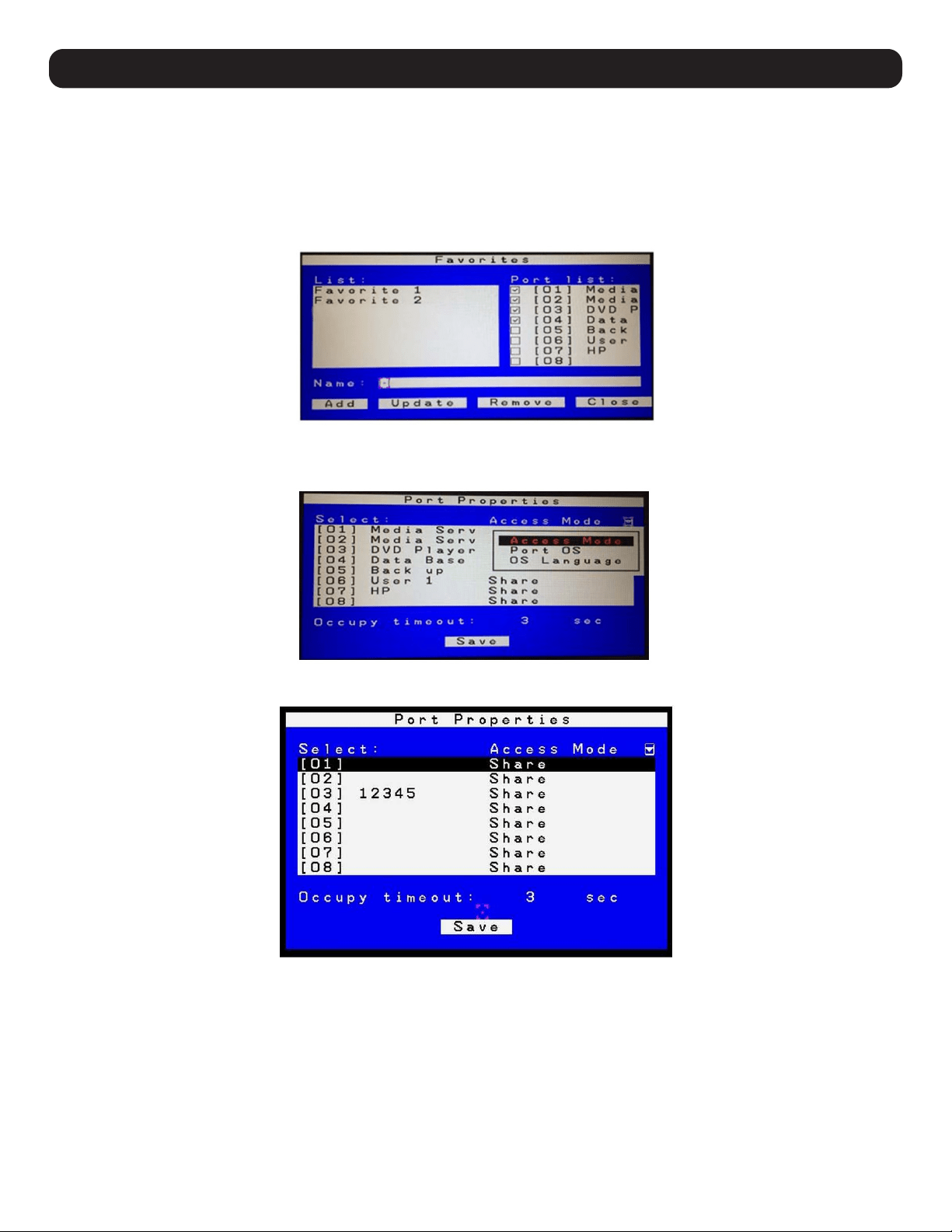
Ctrl + C: Port properties
The Port Properties page sets the Access Mode, Ports OS, and OS Language for each port.
Access Mode
Access Mode determines how the port is to be accessed when multiple users have logged on, as follows:
• Exclusive: The first user to switch to the port has exclusive control over that port. No other users can view the port. The Timeout function
does not apply to ports with this setting enabled.
• Occupy: The first user to switch to the port has control over that port. However, additional users may view the port’s video display. If the user
controlling the port is inactive for longer than the time set in the Timeout box, port control is transferred to the first user to move the mouse
or strike the keyboard.
• Share: Users simultaneously share control over the port. Input from the users is placed in a queue and executed chronologically. Under these
circumstances, users can take advantage of the Message Board to communicate with one another for control of the keyboard and mouse,
as well as keyboard, mouse, and video of a Share port.
9. KVM Operation
27
9. KVM Operation
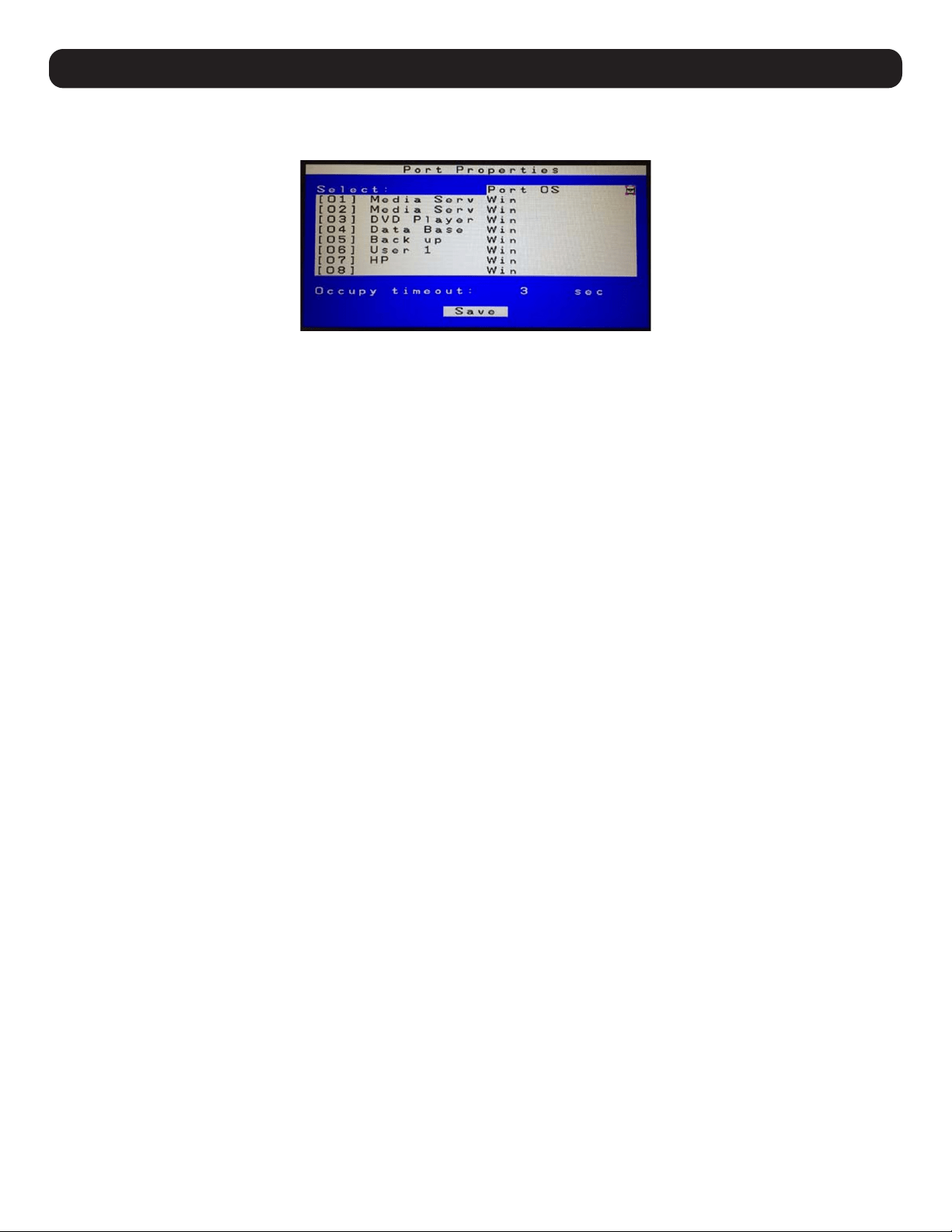
Port OS
Specifies the operating system the server on the connected port is using. Choices are Win, Mac, Sun, and Other. The default is Win.
OS Language
Specifies the OS language used by the server on the connected port. Use the drop down list to view the available choices. The default is US
English.
28
10. Logging In to the KVM over IP
Three methods can be used to connect to the KVM switch over IP: Web Browser, AP Windows Client and AP Java Client. The web interface
appearance will vary slightly, depending on which method is used.
10.1 Web Browser
The B030-008-17-IP can be accessed via an internet browser running on any platform. To access the device:
1. Open the browser and specify the IP address of the switch to access in the browser’s URL bar.
Note: For security purposes, a login string may have been set by the administrator. If so, include a forward slash and the login string, along with the
IP address when logging in. (e.g. 192.168.0.100/abcdefg). If the IP address and/or login string is not known, contact your System Administrator.
2. When a Security Alert dialog box appears, accept the certificate (it can be trusted). If a second certificate appears, accept it as well.
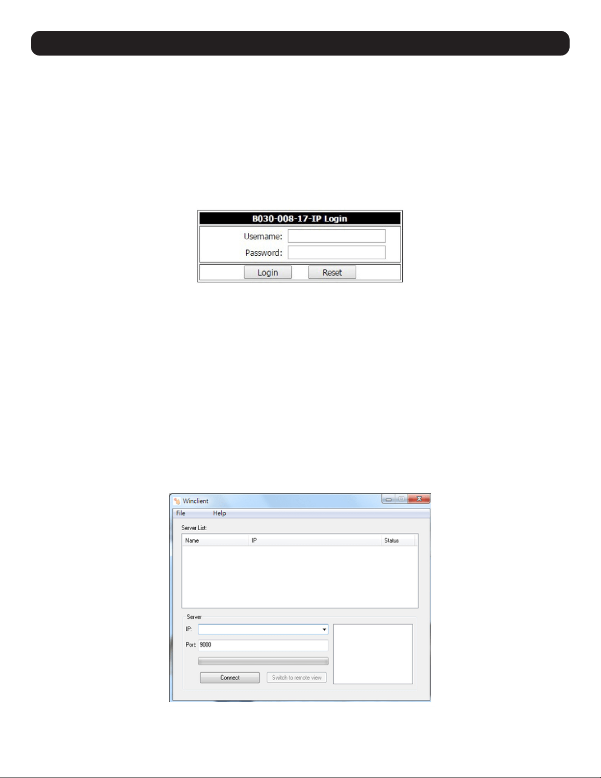
Once all certificate(s) are accepted, the login page will appear.
3. Provide your username and password (set by the administrator), then click Login to access the Web Configuration Interface Main Page.
10.2 AP Windows Client Login
When connecting the KVM switch via web browser is not desired or feasible, the AP Windows Client found on the included CD-ROM provides
non-browser access to the KVM switch via a Windows computer. If access to the AP Windows Client software is restricted, contact your System
Administrator.
Notes:
• The AP Windows Client can also be downloaded from the Web Configuration Interface.
• The AP Windows Client requires Direct X 8.0 or higher be installed on your computer.
1. Save the AP Windows Client to a desired location on a Windows computer.
2. Double-click on the file and follow the installation instructions.
3. When the installation is complete, a shortcut icon will be added to the desktop, and a program entry will be made in the Windows start
menu. Double-click on the icon or select the program entry in the start menu to open the AP Windows Client.
4. The AP Windows Client main screen will appear.
29
10. Logging In to the KVM over IP
5. The AP Windows Client will search the network for any KVM switches and display their Model Name(s) and IP Address(es) in the main
screen’s Server List. If the KVM you wish to connect to is displayed in the list, highlight it and click the Login button. If not, enter the IP
address and port number assigned to it and click the Login button.
Note: The default port number assigned to the KVM is 9000.
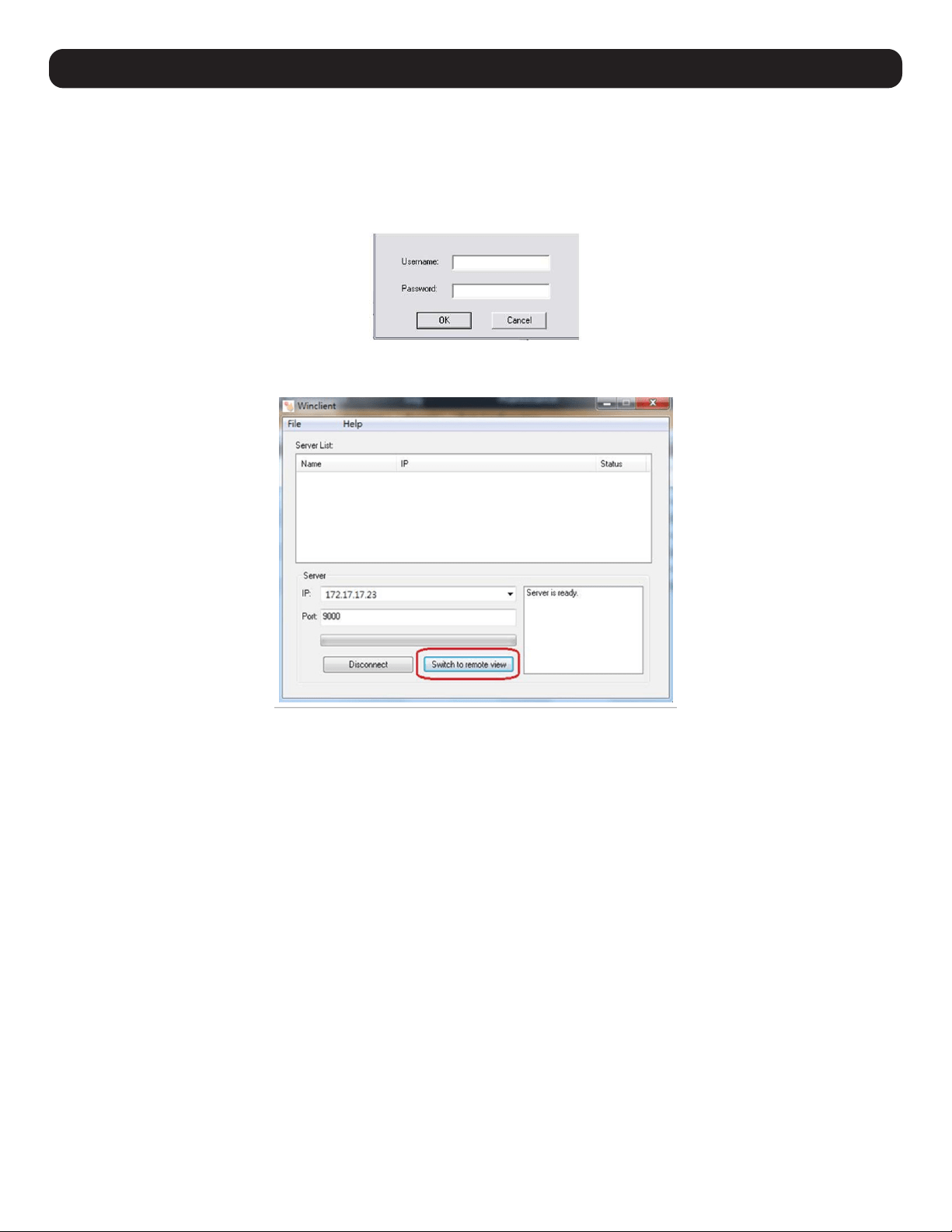
6. A prompt will appear asking to enter your username and password. If accessing the KVM for the first time, enter in the username
administrator and the password password. For security purposes, changing the username and password is strongly recommended.
7. After entering the username and password, the Switch to Remote View button on the main screen will become active. Click on the Switch
to Remote View button to remotely connect to the KVM switch.
30
10. Logging In to the KVM over IP
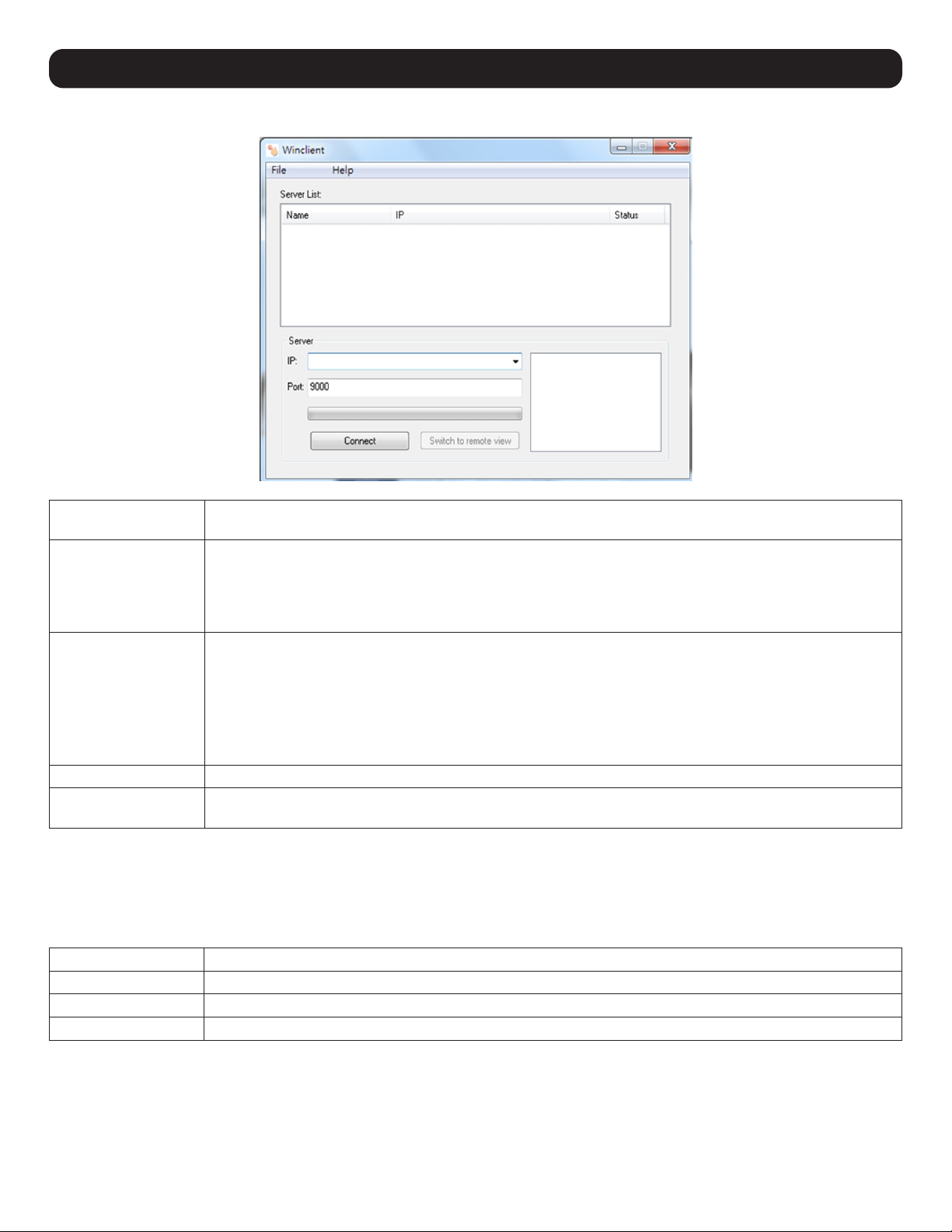
AP Windows Client Connection Screen
Menu Bar The Menu Bar contains two menus: File and Help. The File Menu allows the operator to Create, Save, and Open
Work files. The Help Menu displays the AP Windows Client version number.
Server List Each time the WinClient.exe file is run, it searches the User’s LAN segment for B030-008-17-IP KVM Switches
and lists in the box any that are found. Double-click on any of the devices in this list to connect.
Note: For a switch to appear in the Server List, the Enable Client AP Device List check box in the Operating Mode page of the
Web Interface’s Device Management section must be checked and the Program service port in the Network page must be set to
the same number as in the AP Windows Client Port field.
Server This area is used when connecting to a B030-008-17-IP KVM Switch at a remote location:
• Click on the IP drop-down and select an address from the list. If the desired address is not listed, enter the
target IP address in the IP field and its port number in the Port field.
• Once the IP address and port number have been specified, click Connect to show a login dialog box. Enter the
username and password as provided by your system administrator and click OK to establish a connection with
the B030-008-17-IP KVM Switch.
• When the session has ended, click Disconnect to terminate the connection.
Message List Lists status messages regarding the connection to the B030-008-17-IP.
Switch to Remote View Once a remote connection with a B030-008-17-IP KVM Switch has been established, this button becomes active.
Click the button to switch to the KVM Switch’s Web Interface Page.
The File Menu
The File Menu allows the operator to Create, Save, and Open Work Files. A Work File consists of all the information specified in a Client
session. This includes the items in the Server List and Server IP List.
Whenever a user runs the Client program, it opens with the values contained in the current Work File (i.e. values that were in effect when the
program was last closed).
New Allows the user to create a named work file so its values will be saved and available for future use.
Open Allows the user to open a previously saved work file and use the values contained in it.
Save Allows the user to save the values presently in effect as the current work file.
Exit Exits the AP Windows Client.
31
10. Logging In to the KVM over IP
10.3 AP Java Client Login
In cases when an Administrator does not want the KVM Switch to be available via browser and the remote user is not running Windows, the AP
Java Client provides access to the KVM switch.
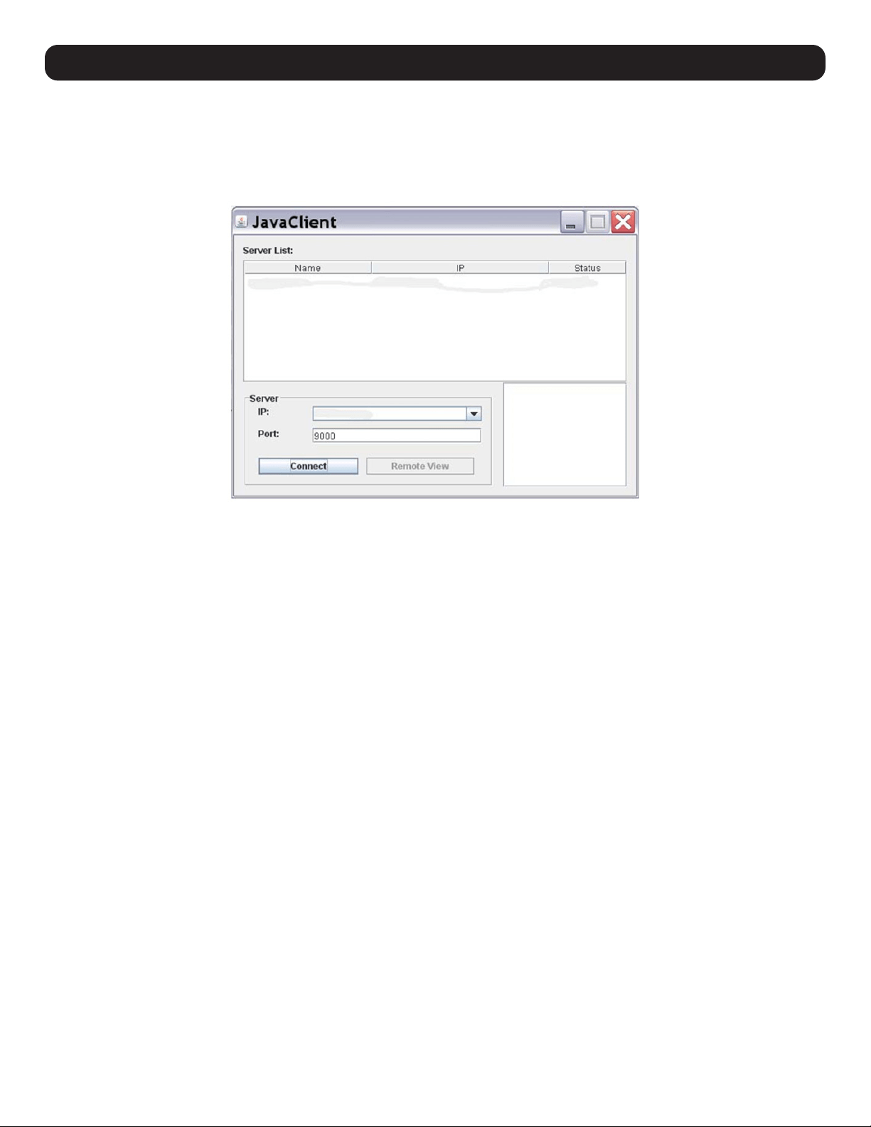
After downloading the AP Java Client, double-click on the program download location on your hard disk to show the connection screen. The AP
Java Client connection screen is the same as the Windows version, except it does not contain a menu bar with File and Help menus.
1. If your KVM is displayed in the Server List, connect by highlighting the desired KVM and clicking the Connect button.
Note: For a switch to appear in the Server List, the Enable Client AP Device List check box in the Operating Mode page of the Web Interface’s Device
Management section must be checked and the Program service port in the Network page must be set to the same number as in the AP Windows Client Port
field.
2. If your KVM does not display in the Server List, enter its IP address in the IP server field and click the Connect button.
3. A prompt will appear requesting a username and password. Enter your username and password, then click OK.
4. Once connected, the Remote View button will be activated. Click on it to access the KVM remotely. Click the Disconnect button to log out
of the KVM switch.
32
11. KVM Web Interface
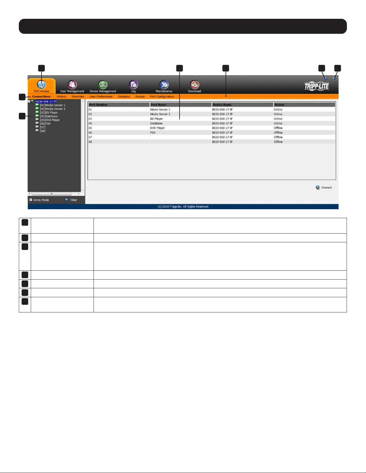
11.1 Web Interface Main Page
When logging into the KVM switch, the following page displays:
1
Tab Bar The Tab Bar consists of category icons that direct to various interfaces used to operate the KVM switch.
The icons displayed in the Tab Bar depend on the user type and permissions.
2
Menu Bar The Menu Bar consists of subcategories that display, depending on the user type and permissions.
3
Sidebar The Sidebar displays a Tree Diagram listing all functions available for the chosen category and subcategory.
Clicking on one of the Sidebar functions will show the corresponding interface in the Interactive Display
Panel. A Filter button located at the bottom of the Sidebar displays only the parts of the Tree Diagram that
have been filtered.
4
About Shows the KVM switch firmware version.
5
Logout Logs out the user of the KVM switch.
6
Welcome Message When enabled, displays a welcome message (disabled by default).
7
Interactive Display Panel This is the main work area of the Web Interface. Different interfaces are displayed, depending on the
category, subcategory and sidebar selections.
1 7 6 4 5
2
3
33
11. KVM Web Interface
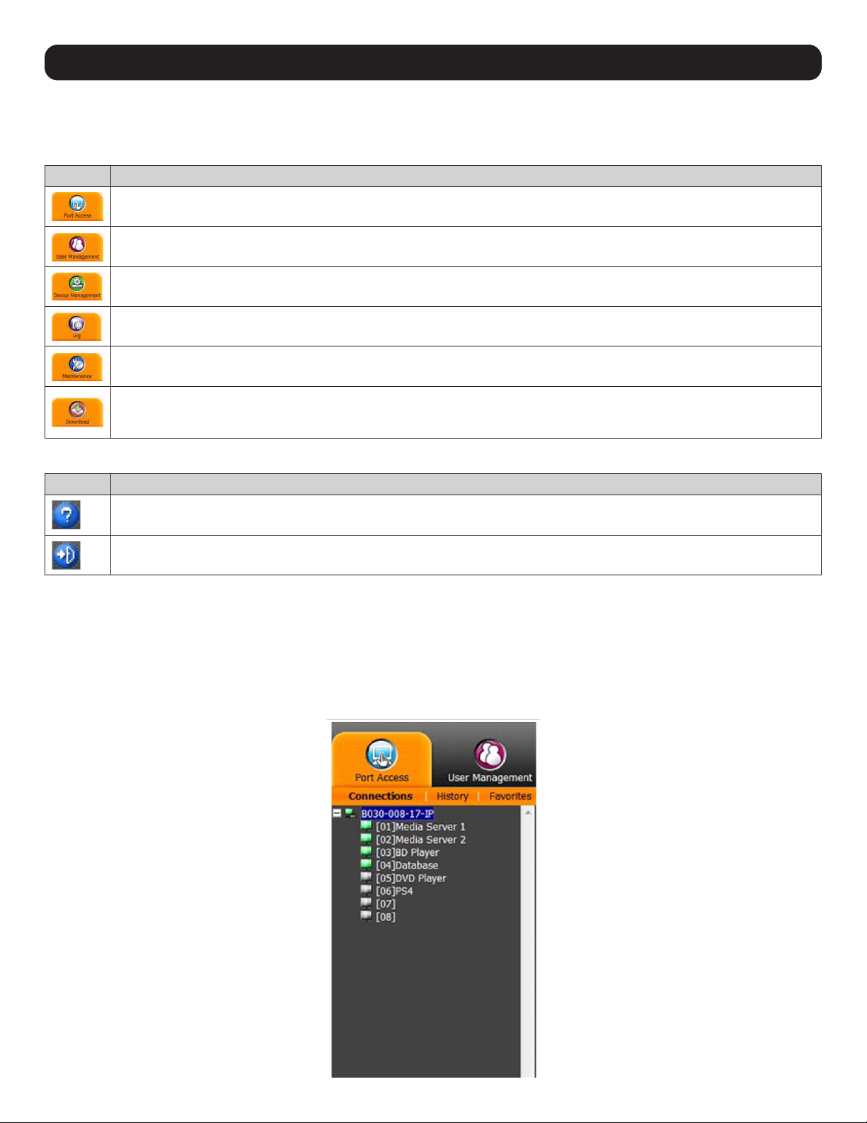
11.1.1 Tab Bar
The icons types and quantity appearing on the tab bar are determined by user type and the permissions assigned when the account was
created. The functions associated with each of the icons are explained in the table below.
Icon Description
Port Access: Is used to access and control the devices on the KVM switch installation. This page is available to all users.
User Management: Is used to create and manage Users and Groups, and to assign devices to them. This page is available to
the Super Administrator and Administrators; ordinary users do not have access.
Device Management: Is used by the Super Administrator to configure and control the overall operation of the KVM switch. This
page is available to Super Administrators or Administrators/Users who have been given access.
Log: This page displays the log file contents.
Maintenance: Is used to install new versions of the KVM Switch firmware. This page is available to Super Administrators or
Administrators/Users who have been given access.
Download: Users with appropriate permission can click this icon to download the log server, AP Windows Client and AP Java
Client. This page is available to all users, although the downloads a User can access is determined by the Super Administrator or
Administrator.
There are two small icons in the upper right-hand corner of the page. Their functions are:
Icon Function
Initiates a panel with information about the B030-008-17-IP firmware version.
Log outs and ends the B030-008-17-IP session.
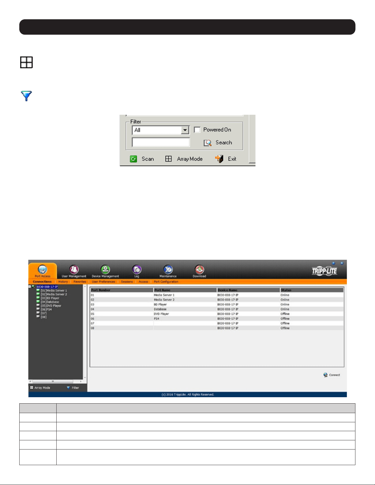
11.2 Port Access
The Port Access section in the OSD is where users can access KVM ports and control settings affecting that access.
11.2.1 Connections
The KVM switch and its ports are listed in a tree structure at the left of the panel.
34
11. KVM Web Interface
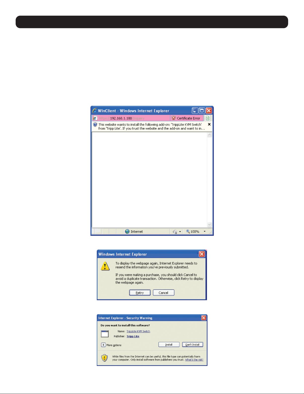
When accessing a port for the first time via web browser, users will experience a series of prompts:
Internet Explorer
When logging onto the KVM switch via Internet Explorer, the default viewer is the Windows ActiveX viewer. To use the Java Viewer when
accessing the KVM switch via Internet Explorer, the Viewer setting in the User Preferences page must first be updated.
Note: Windows 7 users must run Internet Explorer as an administrator for the Active X control to work properly. The user will not be able to access the connected
computers if Internet Explorer is not running as an administrator.
1. When using the Windows ActiveX Viewer and clicking on a port for the first time, a screen prompt will appear to install the Windows ActiveX
control. Click on the prompt and choose to install the ActiveX control.
Note: The screen may display a page stating that the web page’s certificate cannot be trusted. If this is the case, click on the option to continue to the web
page anyway.
2. Once the ActiveX control is installed, a prompt may appear to resend the information in order to display the web page. Click Retry.
3. A prompt will appear requesting to install the software. Click Install.
35
11. KVM Web Interface
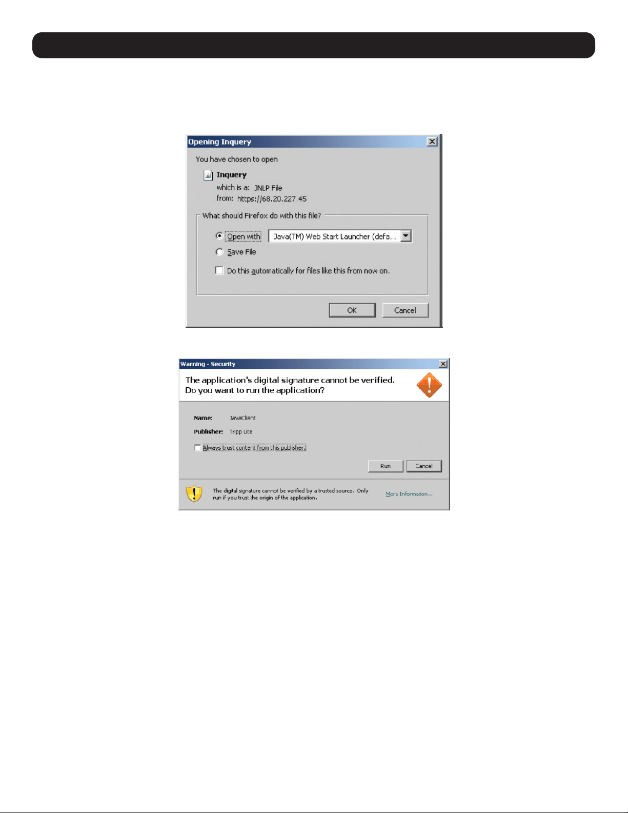
Non-Windows Browser
Users using a non-Windows browser will automatically be connected to remote computers using the Java Viewer.
1. When clicking on a port for the first time, a prompt will appear to run the Java Viewer. Click OK. To avoid this prompt every time you access
a port, check the Do this automatically for files like this from now on box.
2. A prompt to run the Java Viewer will appear. Check the Always trust content from this publisher (Tripp Lite) box, then click Run.
11.2.2 Port Selection List
• Users only see the ports they have been given access to.
• Ports are located under their parent switch. Click the Plus (+) in front of a switch to expand the tree and view the ports underneath it.
• When expanded, a Minus (-) appears before the KVM’s device name. Click the Minus (-) to collapse the tree and hide the ports.
•
A port’s ID number is displayed in brackets next to the port icon. For convenience, each port can be given a unique name in addition to this ID.
• Online KVM switches and ports will have green monitor screen icons. Gray monitor screens indicate offline devices and ports.
11.2.3 Port Naming
For convenience, each port can be given a unique name. To assign, modify or delete a port name, follow the instructions below.
Note: Administrators and Users must be allowed configuration access to a KVM or computer port in order to edit the port name.
1. Click once to highlight the port you want to edit, wait one second and click on it again.
Note: This is not a double-click; it involves two separate clicks. Double-clicking switches the user to the device attached to the port.
2. After a moment, the display will change to provide a text input box. Enter a name for the port (or change/delete a previous one). The
maximum number of characters allowed for a port name is 20. Any combination of letters, numbers, and symbols on the keys of keyboards
with PC US English layout can be used.
3. Once finished editing the port name, press [Enter] or click anywhere outside of the input box to complete the operation.
36
11. KVM Web Interface
11.3 Web Interface Icons and Controls
Panel Array Mode
Panel Array Mode permits port activity to be monitored automatically. When activated, the screen displays a grid of panels, with each
panel representing a port on the installation. Only ports that are online and user accessible are displayed. Offline or non-accessible
ports are left blank.
Filter
Filter controls which ports are displayed in the Port Selection List, as well as which ports are scanned when Auto Scan Mode is initiated.
When Filter is clicked, the bottom panel changes will appear as shown in the image below:
All – with no other filter options selected, lists all of the ports on the installation.
• Checking the Powered On box only lists ports that have their attached devices powered on.
• The text input field and Search button allow the user to input a search string so that only matching ports appear in the list.
• Clicking Exit closes the filter dialog.
11.4 Interactive Display Panel
11.4.1 Device Level
When a KVM switch is selected in the Sidebar tree, the ports accessible to the logged-on user will appear.
Attribute Description
Port Number The KVM switch port the computer or KVM is connected to.
Port Name If a port is assigned a name, it is displayed here.
Device Name The name of the KVM switch the port is on.
Status Current status of the computer or KVM connected to the port; Online or Offline.
Connect A Connect icon will be located underneath the port list. Highlight a port and click Connect to open up a remote session with
the selected port displayed.
37
11. KVM Web Interface
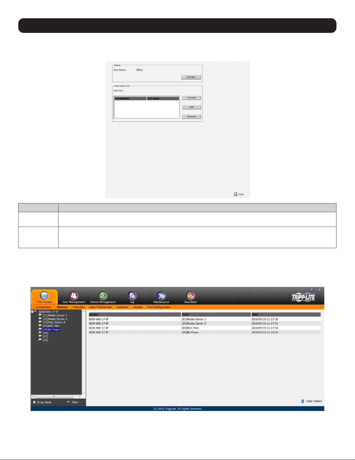
11.4.2 Port Level
When a port is selected in the Sidebar tree, the port connection and configuration options will appear.
Section Description
Status Displays the Port Status; whether it is online or offline, and whether virtual media can be mounted to it. Click the Connect
button to open a remote session with the selected port displayed.
Associated Link Each port can have additional ports associated with it, so that the user can access multiple ports via one connection page.
Associated Links can be added/removed from the Port Configuration subsection. When ports are available in the Associated
Link section, simply highlight one and click the Connect button to open a remote session with that port displayed.
11.5 History
The History page provides a record of each time a port was accessed as well as quick access to the most recently used ports. Users can
access a port in the main panel by double-clicking it.
• If there are more entries than there is room on the screen, a scroll bar appears to scroll up and down to see the entire record.
• To clear the record and start over, click the Clear History button in the bottom-right corner of the page.
Note: The sort order of the information displayed can be changed by clicking the column headings.
38
11. KVM Web Interface
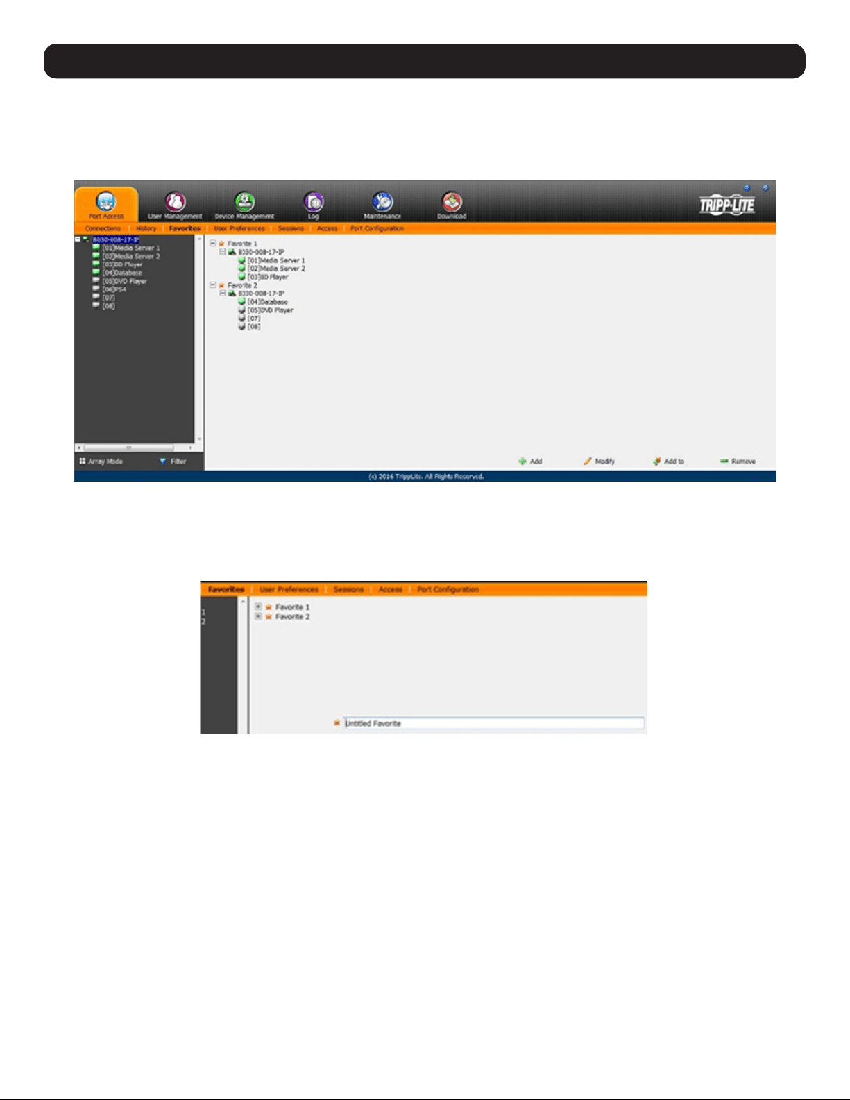
11.6 Favorites
Favorites is similar to a bookmarks feature, where frequently visited ports can be listed on this page. Open this page and select the port
instead of searching for it in the tree view.
Note: Each Favorites bookmark created is a unique folder in which multiple ports can be saved.
Adding a Favorite
To add a port to Favorites:
1. Right click in the main panel. Click on the Add Favorite option that appears or click Add in the bottom-left of the main panel. An entry
appears named “Untitled Favorite”.
2. Click inside the text entry box to erase “Untitled Favorite” and enter the desired name.
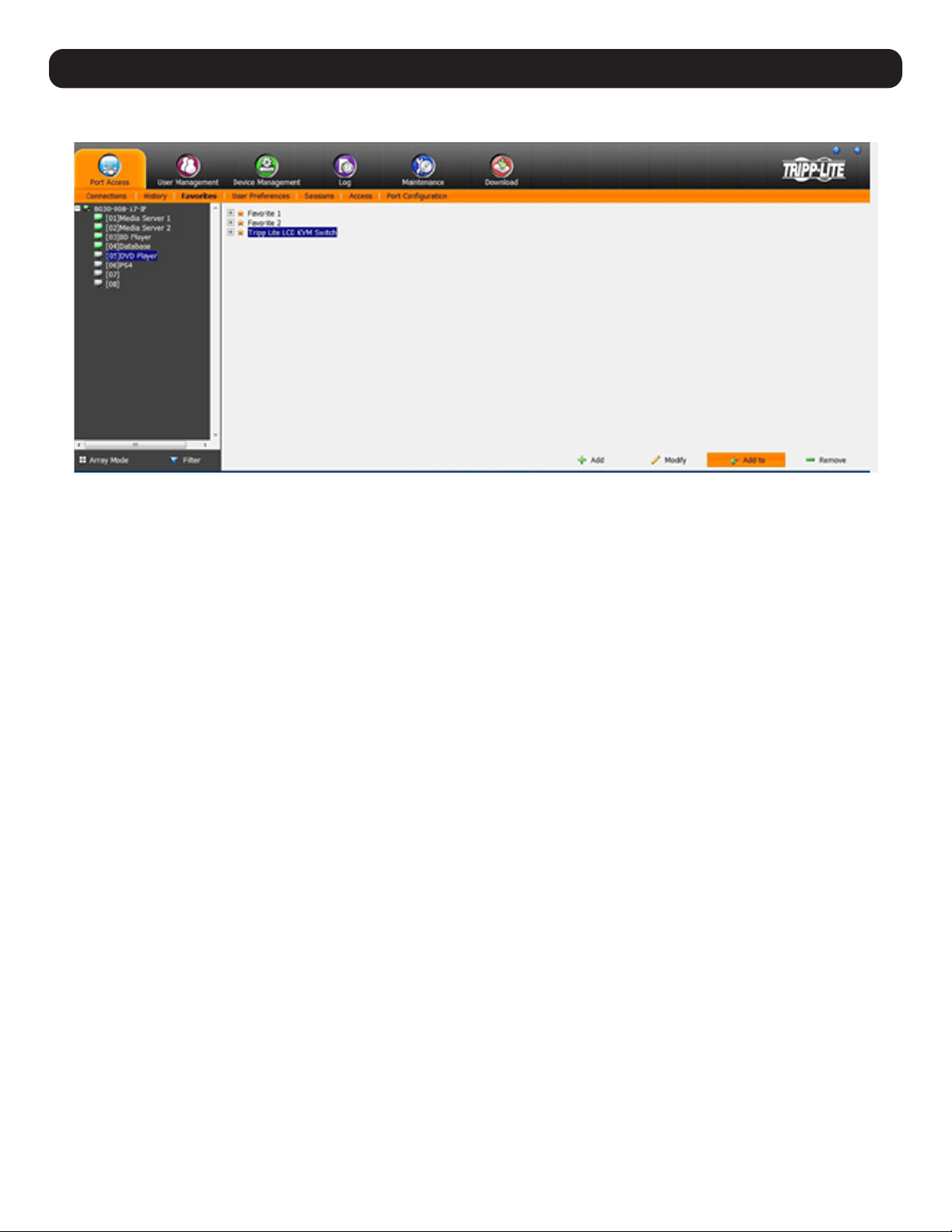
3. To add a port, drag it from the Port Select list and drop into the Favorites bookmark just created. A port can also be added by right-clicking
on it and selecting Copy. After copying, right-click on the Favorites bookmark and select Paste. One final way to do this is to select the
Favorites bookmark in the main panel and the desired port in the tree list and then click Add to at the bottom of the main panel. The KVM
switch the port is connected to goes into the Favorites bookmark along with the port. The port is located under the switch, as it would be in
the tree view on the left-hand panel.
39
11. KVM Web Interface
4. Repeat step 3 for any additional ports to add to the Favorites bookmark.
Modifying a Favorite
To modify a Favorites bookmark, right-click on it and select one of the options from the pop-up menu that appears. To edit a Favorite’s name,
click on it once, wait a second, then click again. You can edit the name after the display changes to provide a text input box. You can also
select the Favorite in the main panel, then click Modify at the bottom of the main panel.
40
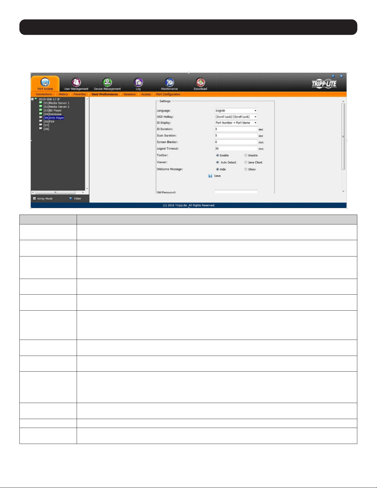
11.7 User Preferences
The User Preferences page allows users to set up their own individual working environments. The KVM Switch stores a separate record for each
user profile, and sets up the working environment according to the Username that was used to access the KVM switch.
Setting Description
Language Selects the interface language. Options include English (default), Spanish, French, German, Russian, Italian,
Japanese, Korean, traditional Chinese and simplified Chinese.
OSD Hotkey Selects which hotkey controls the OSD function. You can choose from the following options; [Scroll Lock] [Scroll
Lock], [Ctrl] [Ctrl], [Alt] [Alt], [Shift] [Shift] and [Print Screen] [Print Screen]. The default is [Scroll Lock] [Scroll Lock].
ID Display Selects how the Port ID is displayed: the Port Number alone (PORT NUMBER); the Port Name alone (PORT NAME);
or the Port Number plus the Port Name (PORT NUMBER + PORT NAME). The default is PORT NUMBER + PORT
NAME.
ID Duration Determines how long a Port ID displays on the monitor after a port change has taken place. Choose a duration from
1—255 seconds. The default is 3 seconds. A setting of 0 (zero) means the Port ID is always on.
Scan Duration Determines how long the focus dwells on each port as it cycles through the selected ports in Auto Scan Mode.
Choose a value from 1—255 seconds. The default is 5 seconds; a setting of 0 disables the Scan function.
Screen Blanker If there is no input from the console for the amount of time set with this function, the screen is blanked. Choose
a value from 1—30 minutes. A setting of 0 disables this function. The default is 0 (disabled). When the screen is
blank, simply moving the mouse over the screen will make it appear once again.
Note: This setting affects the local console monitor only.
Logout Timeout If there is no user input for the amount of time set with this function, the user is automatically logged out. A login is
required before the KVM Switch can be accessed again. The default is 30 minutes.
Toolbar The Toolbar option enables/disables the OSD Toolbar. As all of the features of the OSD Toolbar are available in the
Control Panel, consider disabling it; the default setting is enabled.
Viewer The Viewer option allows you to choose what viewer is used to access a port.
• Auto Detect – The KVM switch will automatically choose which viewer to use based on the web browser. The
Windows Viewer will be used for Internet Explorer and the Java Viewer will be used for all other browsers.
• Java Client – The KVM switch will always use the Java Viewer, regardless of what browser is being used.
Welcome Message The Welcome Message option allows you to show or hide the welcome message that appears in the upper-right
corner of the screen. It is disabled by default.
Save To apply any changes, you must click Save before exiting.
Changing a Password To change a password, the user must enter the old password and the new password. The new password will need to
be entered twice for security purposes. Once entered, click Save to apply the change.
11. KVM Web Interface
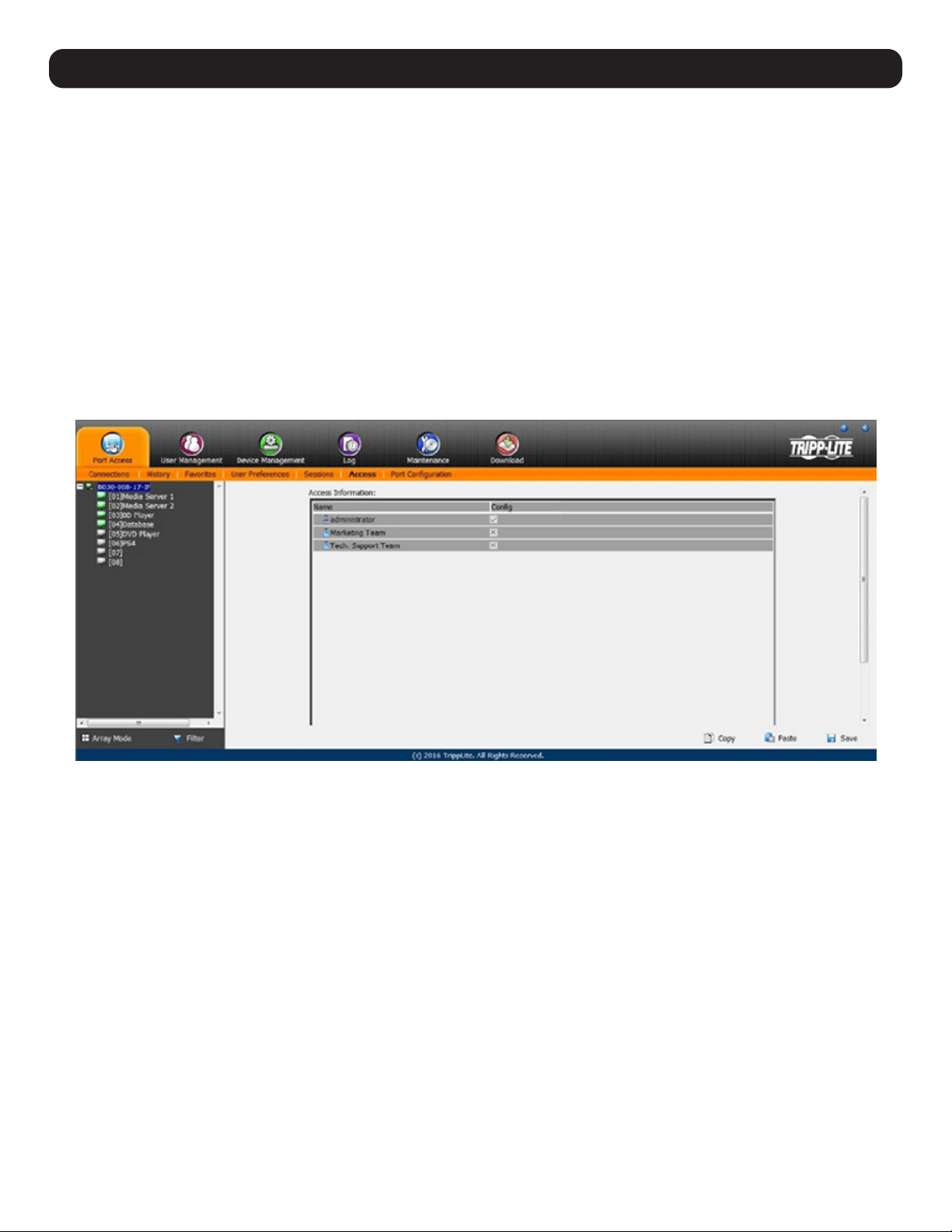
41
11. KVM Web Interface
11.8 Sessions
The Sessions subsection allows Super Administrators and Administrators to view users logged in to the KVM switch, and provides information
about each session. Super Administrators can view all user accounts logged in to the KVM, whereas Administrators are only able to view
Administrator and User accounts.
It also provides the option of ending a session by selecting the account from the Sessions list and clicking the End Session icon. To refresh the
Sessions list to display the most current information, click the Refresh icon.
Note: The Sessions tab is only available for Super Administrators and Administrators. Users will not be able to access it.
11.9 Access
The Access subsection allows Super Administrators and Administrators to set user access and configuration rights for switches and ports. As
with the Sessions subsection, Super Administrators can view all user accounts, whereas Administrators can only view Administrator and User
accounts.
Note: The Access subsection is not available to User accounts and will appear when logged in to the OSD.
If a switch is chosen in the Sidebar, the Main panel will appear as below:
The main panel consists of two columns: Name and Config:
• Name lists all users that have been created.
• Config lists users who have Configuration privileges. A check mark ( √ ) indicates a user has permission to make changes to the switch
configuration settings; an X indicates a user is denied permission to make configuration changes. Click the icon to toggle permission for
Administrators and Users (Super Administrators always have configuration privileges).
• The Copy and Paste buttons at the bottom of the main panel provide a shortcut method of assigning the permissions settings of one port to
any of the other ports. To do so:
1. Select the port whose permissions you want the other port(s) to follow.
2. Click Copy.
3. Select the port you wish to receive the permissions.
4. Click Paste.
5. Once the configuration changes are finished, click Save.
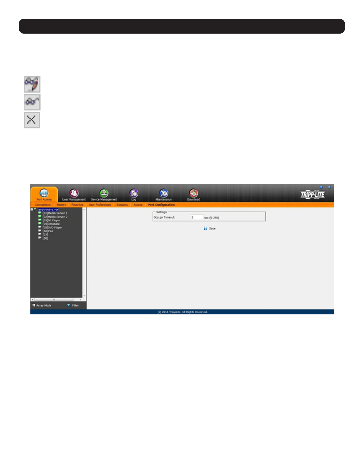
42
11. KVM Web Interface
If a port is chosen in the Sidebar, the Main panel consists of three columns: Name, Access and Config:
• Name lists all users that have been created.
• The Access column is where device access rights are set. To cycle through the choices, click the icon in the row that corresponds to the user
to be configured. The icons are as follows:
(Full Access) – The user can view the remote screen and perform operations on the remote server from his/her keyboard and
monitor.
(View Only) – The user can only view the remote screen and cannot perform any operations.
(No Access) – No access rights; the Port will not appear on the User’s list on the Main Screen.
• Config sets or denies permission for the user to make changes to a port’s configuration settings. A check mark ( √ ) indicates a user has
permission; an X indicates a user does not have permission.
11.10 Port Configuration
The Port Configuration subsection allows Super Administrators and Administrators to edit port properties settings and add/remove associated
links. When the master KVM is highlighted and the Port Configuration subsection is selected, the following screen appears.
The only setting that appears on this page is the Occupy Timeout setting. This setting controls the amount of inactivity time before a port set
to Occupy (see Access Mode in the table on the following page for details) is opened for access by another user. Enter a value from 0 to 255
seconds. The default is 3 seconds.
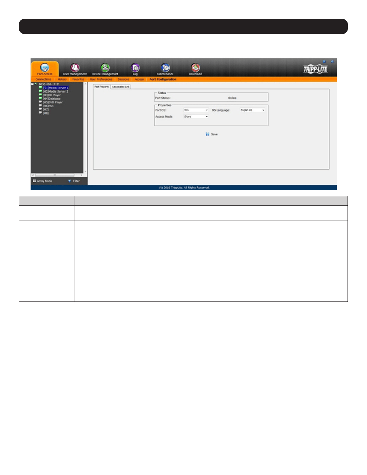
43
11. KVM Web Interface
When a standard port is highlighted and the Port Configuration subsection is selected, a screen opens up containing two sections; Port
Property and Associated Link. The Port Property section is opened first by default.
Field Explanation
Port OS Specifies the operating system the server on the connected port is using. Choices are Win, Mac, Sun, and Other.
The default is Win.
OS Language Specifies the OS language being used by the server on the connected port. Drop down the list to see the available
choices. The default is English US.
Access Mode Defines how the port is accessed when multiple users have logged on.
• Exclusive: The first user to switch to the port has exclusive control over the port. No other users can view the port.
The Timeout function does not apply to ports with this setting.
• Occupy: The first user to switch to the port has control over the port. However, additional users may view the port’s
video display. If the user controlling the port is inactive for longer than the time set in the Timeout box, port control
is transferred to the first user to move the mouse or strike the keyboard.
• Share: Users simultaneously share control over the port. Input from the users is placed in a queue and executed
chronologically. Under these circumstances, users can take advantage of the Message Board to communicate with
one another regarding control of the keyboard and mouse, or keyboard, mouse and video of a Share port.
Once configuration changes have been made, click Save.
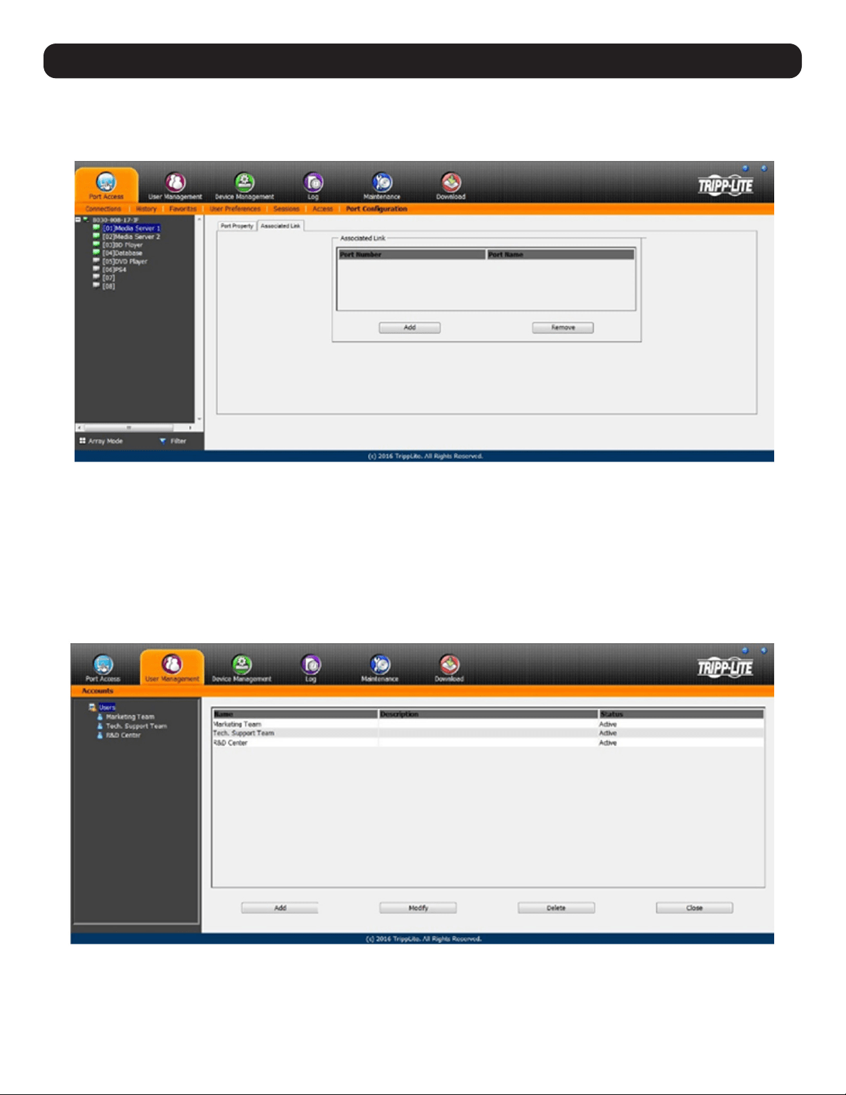
44
11.11 Associated Link
This page associates links to other ports in the installation with the highlighted port. When an associated link is made, it is displayed in the
Associated Link table of the port’s Connections screen.
To add an associated link, click the Add button, enter the desired port number in the box that appears, and click the OK button. It will then
appear in the list of associated links. To remove a link, simply highlight it and click the Remove button.
11.12 User Management
The User Management section allows Super Administrators, and Administrators and Users given User Management permission, to add/edit
accounts on the KVM switch. If an account has not been given User Management permission, the User Management icon will not appear in
the OSD when logging in.
Note: Administrators with User Management permission can only add/edit Administrator and User accounts. Users with User Management permission can only
add/edit User accounts. Super Administrators can add/edit all account types.
11. KVM Web Interface
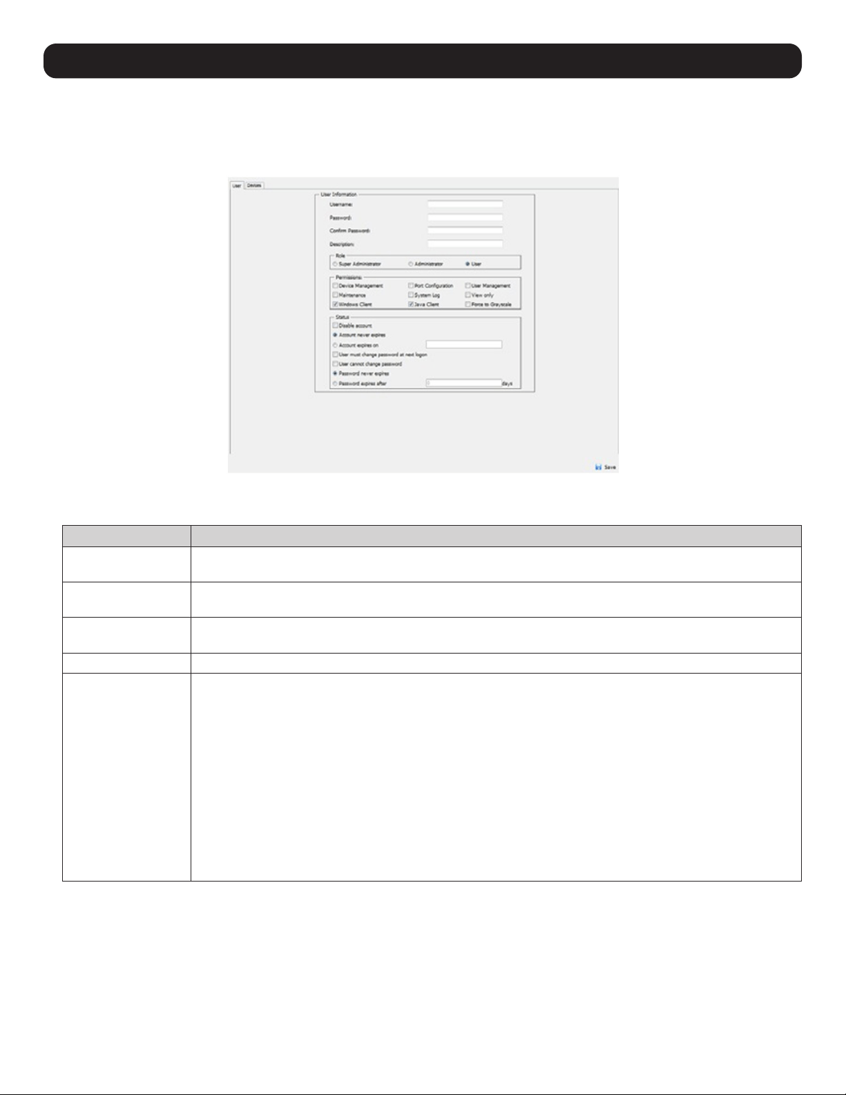
45
11. KVM Web Interface
Adding User Accounts
To add a new user account:
1. Highlight Users from the list on the left side of the page, then click the Add button located at the bottom of the screen. The user
information page will open.
2. Enter the appropriate information for the account being created. The field descriptions can be found in the table below. Click the Save
button when all relevant fields have been filled in.
Field Description
Username Enter an account username. The username can contain up to 16 characters and must meet the Account Policy
requirements set in the Security subsection.
Password Enter an account password. The password can contain up to 16 characters and must meet the Account Policy
requirements set in the Security subsection.
Confirm Password For security purposes, the password must be re-entered. If the password does not match the password entered
in the previous field, you will not be allowed to save the account information.
Description Enter any additional information to describe the account. This is an optional field.
Role Select the account type; Super Administrator, Administrator or User. There is no limitation on the number of each
account type that can be created, only a limit on the number of total accounts. Up to 64 accounts on the KVM
switch can be created.
• Super Administrator – This account type has full access to all aspects of the KVM switch. They can fully access
all computers/devices connected to the KVM, change any and all settings, and add/edit any account type.
• Administrator – This account type defaults at full access to the KVM switch (the same as a Super
Administrator); however, the ports the account has Configuration access to are determined by a Super
Administrator or Administrator who creates/edits the account. In addition, Administrators with User
Management permission are limited to adding/editing Administrator and User accounts.
• User – This account type defaults with no access to the KVM switch, and is only given the initial permissions
of Windows Clients and Java Clients. Super Administrators and Administrators can customize a User profile
as they see fit. If a User is given User Management permission, they are only allowed to add/edit other User
accounts.

46
Field Description
Permissions
Note: For ordinary
users, in addition
to enabling Device
Management, Port
Configuration,
and Maintenance
permissions, the user
must also be given those
rights for each device
and port that he/she will
be allowed to manage.
See 11.12.1 Device
Assignment for details.
The permission settings determine what functionality the account is able to use. Check the box next to the
permission to enable it to that account. Leave it unchecked to deny the account access to that functionality.
• Device Management – Gives an account access to the KVM settings found in the Device Management
section, such as network and advanced network management (ANMS). If this box is not checked, the Device
Management icon will not appear when the account logs into the OSD.
• Port Configuration – Allows an account to edit the Port Configuration settings for individual KVM ports.
• User Management – Allows an account to add/edit other accounts. Administrators can add/edit Administrator
and User accounts. Users can add/edit other User accounts. Super Administrators can add/edit all account
types. If this box is not checked, the User Management icon will not appear when the account logs into the
OSD.
• Maintenance – Gives the account access to the settings and functionality found in the Maintenance section,
which includes upgrading the KVM firmware. If this box is not checked, the Maintenance icon will not appear
when the account logs into the OSD.
• System Log – Gives the account access to the Log section of the OSD, where they can view events that have
taken place on the installation. If this box is not checked, the Log icon will not appear when the account logs
into the OSD.
• View Only – Limits the account to viewing the video of connected computers only. They will not be able to
perform keyboard and mouse functions.
• Windows Client – Gives the account access to the browser and non-browser versions of the Windows client.
• Java Client – Gives the account access to the browser and non-browser versions of the Java client.
• Force to Grayscale – Forces the account to view remote video without color.
Status This section determines how long an account or password is valid until it expires or needs to be changed.
• Disable Account – Disables an account and prevents it from accessing the KVM switch. This provides an
alternative to deleting the account, in which the account can be disabled and then reinstated for future use
without having to re-enter the account settings.
• Account Never Expires – If this option is checked, the account will stay active forever or until deactivated
manually.
• Account Expires On – To set a date for the account to be disabled, check this box and enter in a date in the
corresponding field.
• User Must Change Password at Next Logon – To force the account to change its password the next time they
logon, check this box. The next time the account logs on, the user will be prompted to enter a new password.
• User Cannot Change Password – Check this box to prohibit the user from changing their password.
• Password Never Expires – If this option is checked, the account’s password will stay active forever or until
manually forced to be changed.
• Password Expires After – To force an account to change its password after a certain number of days, check this
box and enter in the number of days until the password expires.
3. Upon clicking Save, a prompt will appear stating that the operation succeeded. Click OK to exit.
Modifying User Accounts
1. Select the desired user’s name from the User List or the Main Panel and click Modify.
2. Make any necessary changes to the user account and click Save.
Deleting User Accounts
1. Select the user’s name from the Main Panel and click Delete.
2. A confirmation dialog box will appear asking if you are sure you want to delete the selected user account. Click OK.
11. KVM Web Interface
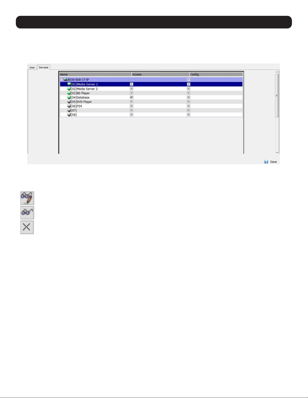
47
11. KVM Web Interface
11.12.1 Device Assignment
When a user logs on to the KVM switch, the ports they are allowed to access are displayed in the port list. Ports they are not allowed to access
are not displayed. Port access rights, as well as access to configuration settings, are assigned on a port-by-port basis in the user Device tab. To
access the Device tab, first access the user information page, then click on the Device tab at the top of the page.
The Device tab page includes a list of the master KVM switch and its ports on the left side, and two permission columns on the right side.
• Access – Determines if the account can access the port, and if so, whether the account is allowed Full Access, View Only access or No
Access.
(Full Access) – The user can view the remote screen and perform operations on the remote server from his/her keyboard and
monitor.
(View Only) – The user can only view the remote screen and cannot perform any operations.
(No Access) – No access rights; the Port will not appear on the User’s list on the Main Screen.
• Config – If the box is checked ( √ ) next to a port, the account is given access to edit the Port Configuration settings.
Note: For Configuration access to take effect, the account must also have been given Port Configuration permission. (Refer to the Adding User Accounts
section in 11.12 User Management for details.)
Once finished assigning permissions, click the Save button. In the confirmation popup, click OK.
Note: You can simultaneously assign to multiple ports using the [Shift] or [Ctrl] keys. To highlight a group of consecutive ports, start by highlighting the first port,
hold down the [Shift] key, then highlight the last port that you wish to highlight. All ports from the first one highlighted to the last will be highlighted. Then click
on any of the permission boxes to change that permission for the highlighted ports. To highlight multiple non-consecutive ports, start by highlighting the first port,
hold down the [Ctrl] key then highlight each additional port one-by-one while continuing to hold down the [Ctrl] key. When all of the desired ports are highlighted,
click on any box to change that permission for all of the highlighted ports.
11.12.2 Device Management
The Device Management section allows Super Administrators and Administrators/Users who have been given permission, to configure and
control the KVM switch.
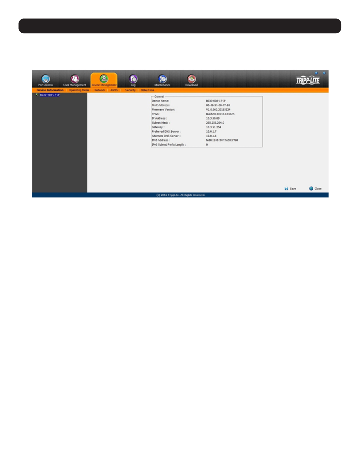
48
11.12.3 Device Information
When the Device Management icon is selected, it opens with the Device Information page displayed.
Note: If you do not have permission to configure the KVM switch, the Device Management icon will not appear when you log onto the KVM.
The General Device Information page displays the name of the selected device, its firmware version, the FPGA (Field-Programmable-Gate-Array)
and information about its network configuration.
11. KVM Web Interface
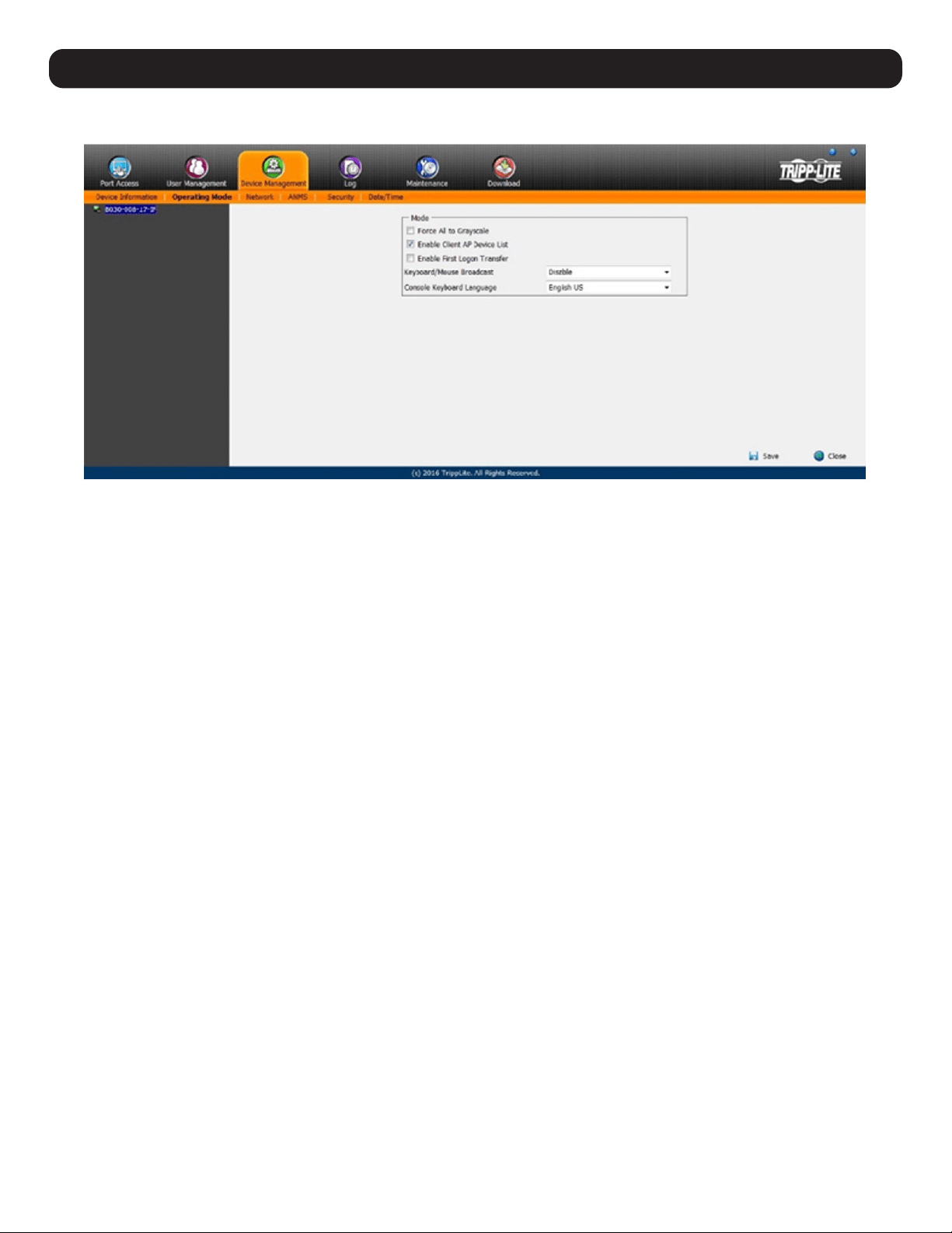
49
11. KVM Web Interface
11.13 Operating Mode
The Operating Mode subsection allows the working parameters of the KVM to be set.
• If Force all to grayscale is enabled, the remote displays of all devices connected to the B030-008-17-IP are changed to grayscale. This can
speed up I/O transfer in low bandwidth situations.
• If Enable Client AP Device List is enabled, the switch will appear in the Server List when using the WinClient or Java Client AP. If this option is
not enabled, the switch will remain connected, but its name will not appear in the Server List.
• If Enable First Logon Transfer is enabled, only the first user to access a port can switch ports. Other users cannot switch ports unless the first
user to logon logs out.
• For the Keyboard/Mouse Broadcast setting, select the desired choice from the dropdown menu.
– If Keyboard Broadcast is enabled, keystrokes will be duplicated on all the attached servers that appear in the Sidebar.
– If Mouse Broadcast is enabled, mouse movements and clicks will be duplicated on all the attached servers that appear in the Sidebar. For
Mouse Broadcast to work correctly, all connected computers must be running the same OS and all screens must have an identical layout.
– Choose Disable to Disable Keyboard/Mouse Broadcast.
• The Console Keyboard Language setting specifies which keyboard mapping is being used by the Local Console keyboard. Select the desired
choice from the dropdown menu.
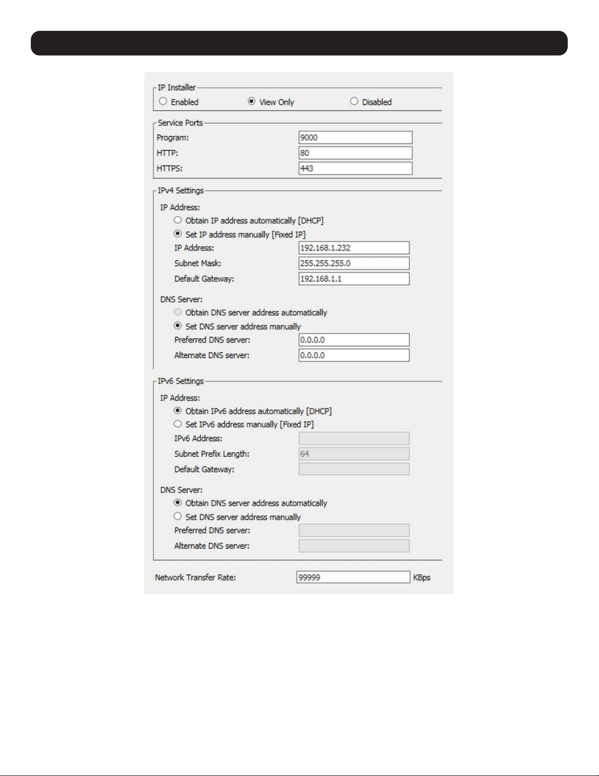
50
12. Network Settings

51
12. Network Settings
Item Description
IP Installer The B030-008-17-IP includes an IP Installer application that allows Windows computers to easily view and edit the KVM’s
network settings. This section determines what access the IP Installer has to the KVM switch.
• Enabled – When selected, the IP Installer can locate the KVM switch on the network and display its current IP address. It
also allows the IP Installer to be used to change the KVM’s IP address.
• View Only – When selected, the IP Installer can locate the KVM switch on the network and display its current IP address,
but it cannot be used to change the KVM’s IP address.
• Disabled – When selected, the IP Installer cannot locate the KVM switch on the network, nor can it be used to change the
KVM’s IP address.
Service Ports This section sets up port numbers allowed by a firewall. If the port numbers on this page are not allowed access by the
firewall, you will not be able to access the KVM switch. Valid entries for all service ports are from 1 to 65535.
Note: A different port number must be entered for each field. If the KVM is connected to a network without a firewall, it doesn’t matter
what these ports are set to, as they will have no effect.
• Program – This is the port number used when accessing connected computers via browser and non-browser Windows and
Java clients. The default value is 9000.
Note: This port number must match the port number for non-browser Windows and Java clients when using to connect to the KVM
switch.
• HTTP – This is the port used for a browser login. The default value is 80.
• HTTPS – This is the port that is used for a secure browser login. The default is 443.
IPv4 Settings
If using an IPv6 IP address, ignore this section.
• Obtain an IP Address Automatically (DHCP) – When this option is checked, the KVM switch will have its IP address
assigned by a DHCP server upon booting up and the remaining fields will be grayed out. This option is checked by default.
• Set IP Address Manually (Fixed IP) – Check this option to manually assign an IP address to the KVM. When checked, the
settings fields below will be activated for you to edit.
• IP Address – Enter the desired IP address here.
• Subnet Mask – Enter the desired Subnet Mask here.
• Default Gateway – Enter the desired Default Gateway here.
• Obtain DNS Server Address Automatically – When this option is checked, the KVM switch will have its DNS Server address
assigned by a DHCP server upon booting up and the remaining fields in this section will be grayed out. If you selected
to set the IP address manually, this option will be grayed out and you will be required to enter the DNS Server address
manually.
• Set DNS Server Address Manually – Check this option to manually assign a DNS Server address to the KVM. When
checked, the settings fields will be activated for editing.
• Preferred DNS Server – Enter the preferred DNS Server address here.
• Alternate DNS Server – Enter the alternate DNS Server address here. This is an optional field.
IPv6 Settings
If using an IPv4 IP address, ignore this section.
• Obtain IPv6 Address Automatically (DHCP) – When this option is checked, the KVM switch will have its IP address
assigned by a DHCP server upon booting up and the remaining fields in this section will be grayed out. This option is
checked by default.
• Set IPv6 Address Manually (Fixed IP) – Check this option to manually assign an IP address to the KVM. When checked,
the settings fields below will be activated for editing.
• IPv6 Address – Enter the desired IP address here.
• Subnet Prefix Length – Enter the desired Subnet Prefix length here.
• Default Gateway – Enter the desired Default Gateway here.
• Obtain DNS Server Address Automatically – When this option is checked, the KVM switch will have its DNS Server address
assigned to it by a DHCP server upon booting up and the remaining fields in this section will be grayed out. If you selected
to set the IP address manually, this option will be grayed out and you will be required to enter the DNS Server address
manually.
• Set DNS Server Address Manually – Check this option to manually assign a DNS Server address to the KVM. When
checked, the settings fields will be activated for editing.
• Preferred DNS Server – Enter the preferred DNS Server address here.
• Alternate DNS Server – Enter the alternate DNS Server address here. This is an optional field.
Network
Transfer Rate
This setting sets the size of the data transfer stream to match your network by setting the rate at which the KVM transfers
data to remote computers. The range is from 4 to 99,999 Kbps. The default is 99999.
After making any network changes, be sure Reset on exit on the Maintenance
System Operation page has been enabled (its corresponding
box is checked), before logging out. This allows network changes to take effect without having to power the switch off.
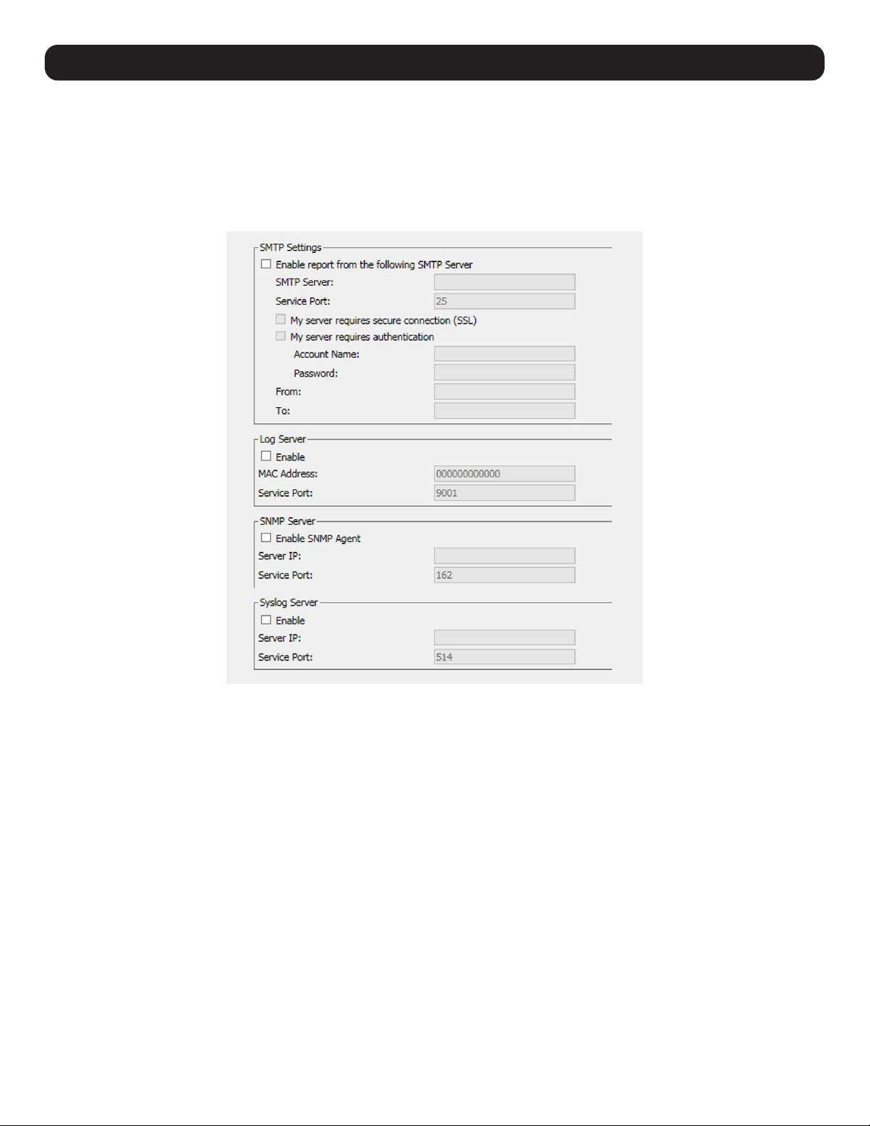
52
12. Network Settings
12.1 Advanced Network Management Settings (ANMS)
The Advance Network management Settings (ANMS) are used to set up login authentication and authorization management from external
sources. It is split up into two pages; Event Destination and Authentication.
Event Destination
The Event Destination page allows the KVM to be set up to record and send notifications of events that take place on the system. With this
page, users can enable and set up notifications via SMTP, SNMP, Syslog Server and the Log Server.
SMTP Settings
The SMTP Settings provide system events notifications emailed via the SMTP server. To set up this feature, follow the steps below.
1. Check Enable report from the following SMTP Server box.
2. In the SMTP Server field, enter the IPv4 address, IPv6 address or domain name of the SMTP server.
3. In the Service Port field, enter the port the Firewall will allow to be used to access the SMTP server. The valid port range is between 1 and
65535. The default port number is 25.
Note: The port number entered must not be the same as any of the ports entered into the Network sub-section (for more information, see the Network
section in 11.12.2 Device Management.)
4. If your server requires a secure SSL connection, check the My server requires secure connection (SSL) box.
5. If your server requires authentication, check the My server requires authentication box.
6. Enter the Account Name and Password for your SMTP server.
7. In the From field, enter the email address that you want the report to show up as being sent from.
Note: Only one email address is allowed in the From field and it cannot exceed 64 Bytes. 1 Byte is equal to 1 English alphanumeric character.
8. In the To field, enter the email address(es) to receive the report.
Note: When entering more than one address, separate them with a semicolon. The size of all email addresses cannot combine to more than 256 Bytes. 1
Byte is equal to 1 English alphanumeric character.
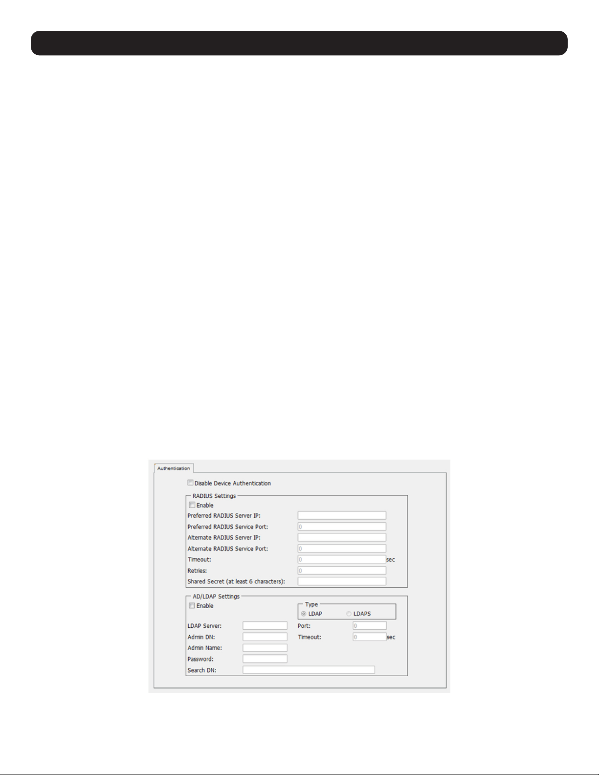
53
12. Network Settings
Log Server
In addition to the OSD’s built-in log, the KVM includes an external Windows-based log server that can be installed on a computer (refer to 17.
Log Server for details). The Log Server section on this page explains where the external log server can be enabled and set up for use. To do
this, follow the steps below.
1. Check the Enable box.
2. In the MAC Address field, enter the MAC address of the computer the log server resides on.
3. In the Service Port field, enter the port the Firewall will allow to be used to access the log server. The valid port range is between 1 and
65535. The default port number is 9001.
Note: The port number entered must not be the same as any of the ports entered into the Network sub-section (for more information, see the Network
section in 11.12.2 Device Management.)
SNMP Server
To enable SNMP traps, follow the steps below.
1. Check the Enable SNMP Agent box.
2. In the Server IP field, enter the IPv4 address, IPv6 address or computer domain name to be notified of SNMP trap events.
3. In the Service Port field, enter the port the Firewall will allow to be used to access the SNMP server. The valid port range is between 1 and
65535. The default port number is 162.
Note: The port number entered must not be the same as any of the ports entered into the Network sub-section (for more information, see the Network
section in 11.12.2 Device Management.)
Syslog Server
To record all the events that take place on the KVM and write them to a Syslog server, follow the steps below.
1. Check the Enable box.
2. In the Server IP field, enter the IPv4 address, IPv6 address or domain name of the Syslog server.
3. In the Service Port field, enter in a port that the firewall will allow to be used to access the Syslog server. The valid port range is between 1
and 65535. The default port number is 514.
Note: The port number entered must not be the same as any of the ports entered into the Network sub-section (for more information, see the Network
section in 11.12.2 Device Management.)
Authentication
The Authentication page allows remote authentication setup via RADIUS and LDAP/S.
Disable Device Authentication
Check this box to disable local login authentication of the KVM switch. If checked, the switch can only be accessed using LDAP, LDAPS, MS
Active Directory and/or RADIUS authentication.
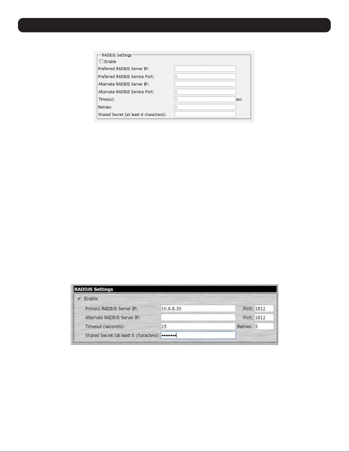
54
12.1.1 RADIUS Settings
To allow authentication and authorization for B030-008-17-IP through a RADIUS server:
1. Check the Enable box in the RADIUS section.
2. Fill in the IP addresses and port numbers for the Preferred and Alternate RADIUS servers.
3. In the Timeout field, set the time in seconds that the KVM Switch waits for a RADIUS server reply before it times out.
4. In the Retries field, set the number of allowed RADIUS retries.
5. In the Shared Secret field, key in the character string to use for authentication between the KVM Switch and the RADIUS Server.
6. On the RADIUS server, Users can be authenticated with the following methods:
– Set the entry for the user as su/xxxx, where xxxx represents the Username given when the account was created in the B030-008-17-IP
User Management page.
– Use the same Username on both the RADIUS server and the B030-008-17-IP.
In each case, the user’s access rights are those assigned in the User Management section of the B030-008-17-IP.
7. Click Save at the bottom of the screen to save all of the settings.
12.1.2 Configuring RADIUS Authentication
The following instructions show how to configure a Windows 2003 server with the B030-008-17-IP.
Note: These steps were taken on a Windows 2003 server with the Internet Authentication Service (IAS) component installed.
B030-008-17-IP
IP: 10.0.1.193
Note: The Shared Secret will be used in communication with the RADIUS server. Only one RADIUS server is used in this scenario so the primary and alternative
RADIUS servers are assigned the same settings.
12. Network Settings
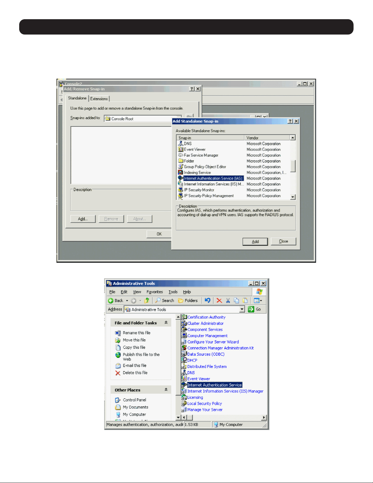
55
12. Network Settings
Win2K3
IP: 10.8.8.30
1. Start the Microsoft Management Console (MMC) and add the Internet Authentication Service by choosing Add/Remove Snap-in from the
console menu. Click Add and select the IAS Snap-in. Choose the Local Computer.
Or go to: Start > Programs > Administrative Tools > Internet Authentication Service.
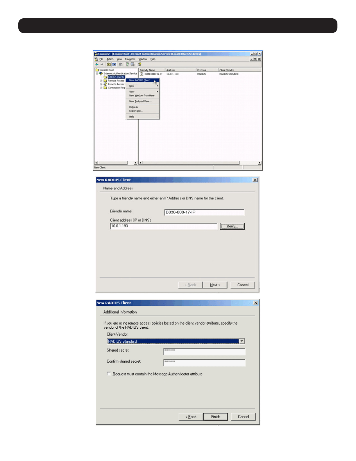
56
2. Create a rule to allow the Access Gateway access to the RADIUS server.
Note: The Shared Secret is the same one used when configuring the B030-008-17-IP.
12. Network Settings
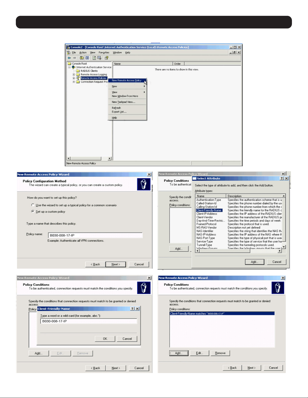
57
12. Network Settings
3. Create a New Remote Access Policy and click Next.
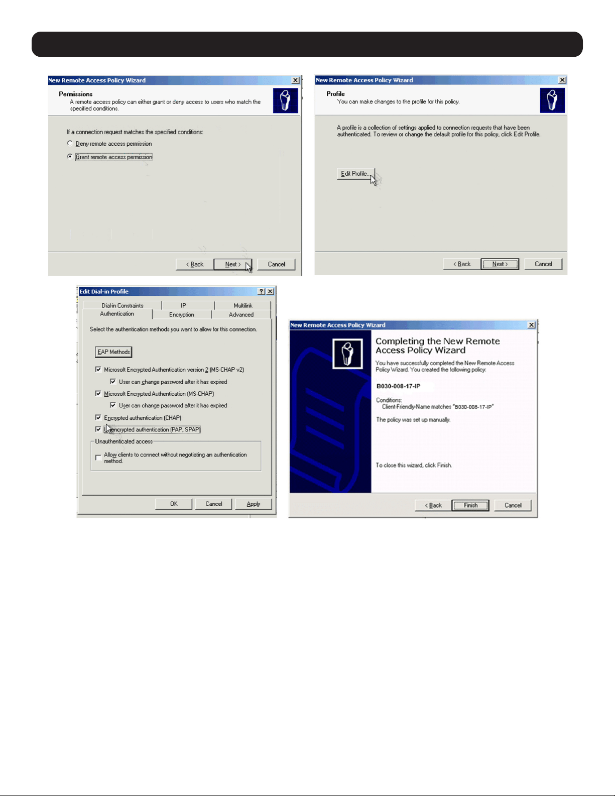
58
12. Network Settings
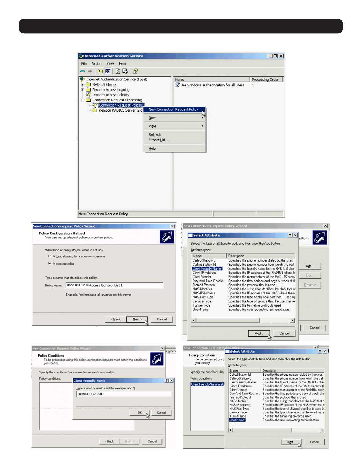
59
12. Network Settings
4. Create an Access Control List Policy (one policy per user).
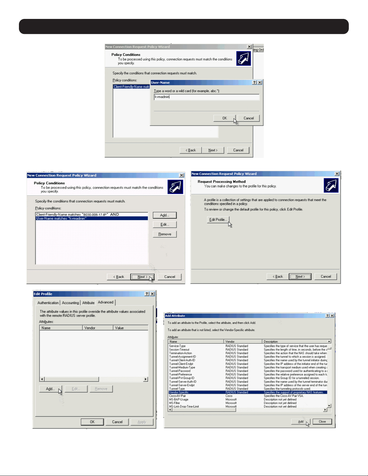
60
Note: kvmadmin is a user created in Win2K3 in advance.
12. Network Settings
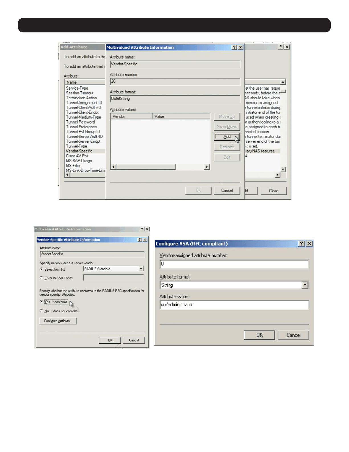
61
12. Network Settings
Click Configure Attribute. In the screen that appears, set the entry for the user as su/xxxx, where xxxx represents the Username given when
the account was created in the B030-008-17-IP User Management page. User access rights will be the same as those assigned to the KVM
switch (refer to 11.12 User Management for more information).
Repeat as needed to set the B030-008-17-IP Access Control List Policy for other users.
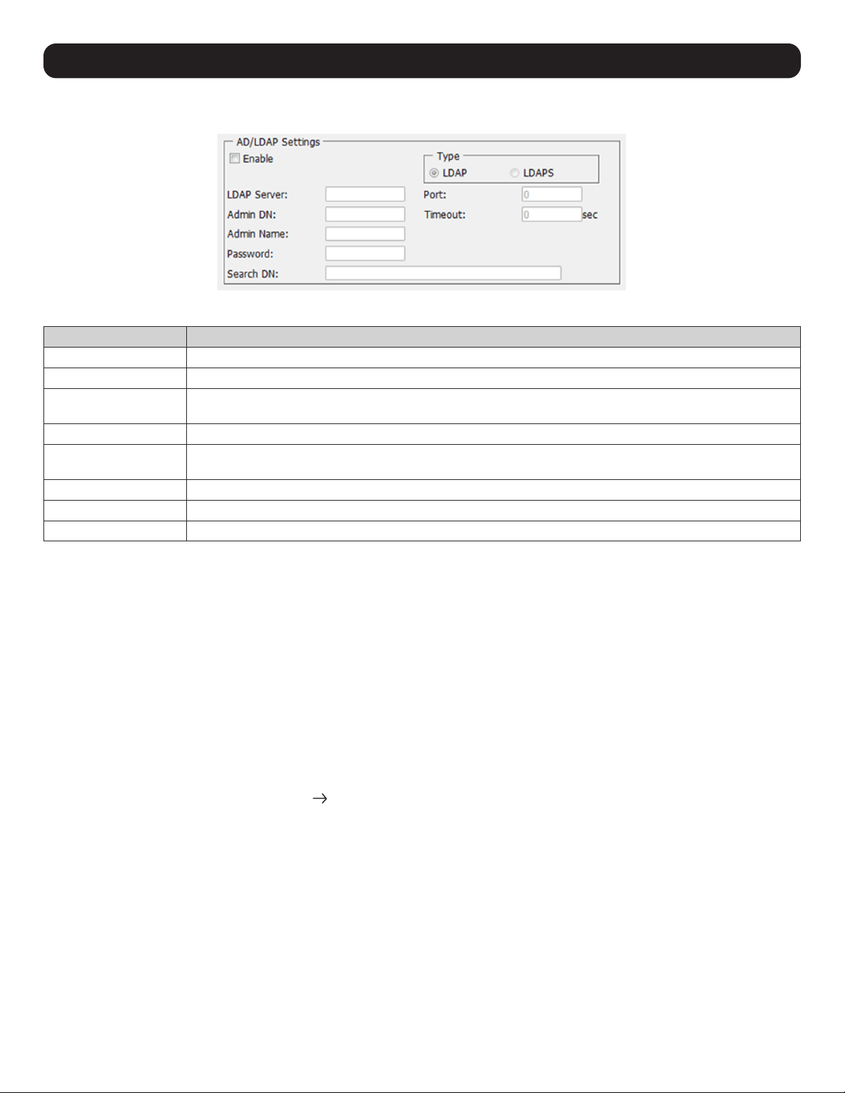
62
12.2 LDAP / LDAPS Authentication and Authorization Settings
To allow authentication and authorization for the B030-008-17-IP via LDAP / LDAPS:
Item Description
Enable Check the Enable box to allow LDAP / LDAPS authentication and authorization.
LDAP / LDAPS Click to specify whether to use LDAP or LDAPS.
LDAP Server IP and Port Fill in the IP address and port number for the LDAP or LDAPS server. For LDAP, the default port number is 389; for
LDAPS, the default port number is 636.
Timeout Set the time in seconds that the KVM Switch waits for an LDAP or LDAPS server reply before it times out.
Admin DN Consult the LDAP / LDAPS administrator to determine the appropriate entry for this field. For example, the entry
might look like: ou=b030-008-017-ip,dc=tripplite,dc=com
Admin Name Enter the LDAP administrator’s username.
Password Enter the LDAP administrator’s password.
Search DN Set the name of the search base. This is the domain name where searches begin for user names.
Click Save at the bottom of the screen to save all settings.
Note: If the LDAP Setting is enabled, the LDAP schema for MS Active Directory must be extended, or an OpenLDAP server must be installed and configured.
Refer to LDAP Server Configuration in the following section for details.
12.2.1 LDAP Configuration — Active Directory
To allow authentication and authorization for the KVM Switch via LDAP or LDAPS, the Active Directory’s LDAP Schema must be extended so
that an extended attribute name for the KVM Switch – userprofile – is added as an optional attribute to the person class.
• Authentication refers to determining the authenticity of the person logging in.
• Authorization refers to assigning permission to use the device’s various features.
In order to configure the LDAP server, complete the following procedures: 1) Install the Windows 2003 Support Tools; 2) Install the Active
Directory Schema Snap-in; and 3) Extend and Update the Active Directory Schema.
Install the Windows 2003 Support Tools
1. On your Windows Server CD, open the Support
Tools folder.
2. In the right panel of the dialog box that appears, double-click SupTools.msi.
3. Follow along with the Installation Wizard to complete the procedure.
Install the Active Directory Schema Snap-in
1. Open a Command Prompt.
2. Enter regsvr32 schmmgmt.dll to register schmmgmt.dll on your computer.
3. Open the Start menu. Click Run and enter mmc /a. Click OK.
4. On the File menu of the screen that appears, click Add/Remove Snap-in, then click Add.
5. Under Available Standalone Snap-ins, double-click Active Directory Schema, click Close, then click OK.
6. From the existing screen, open the File menu and click Save.
7. For Save in, specify the C:\Windows\system32 directory.
8. For File name, enter schmmgmt.msc.
9. Click Save to complete the procedure.
12. Network Settings
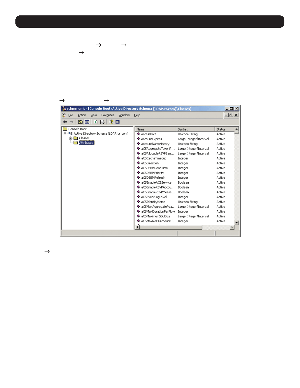
63
12. Network Settings
Creating a Start Menu Shortcut Entry
1. Right click Start; select: Open all Users Programs Administrative Tools.
2. On the File menu, select New Shortcut
3. In the dialog box that appears, browse to or enter in the path to schmmgmt.msc (C:\Windows\system32\schmmgmt.msc) and click Next.
4. In the dialog box that appears, enter Active Directory Schema as the name for the shortcut, then click Finish.
12.2.2 Extend and Update the Active Directory Schema
Step 1 - Create a New Attribute:
a) Open Control Panel Administrative Tools Active Directory Schema.
b) In the left panel of the screen that appears, right-click Attributes:
c) Select New Attribute.
d) In the warning message that appears, click Continue to open the Create New Attribute dialog box.
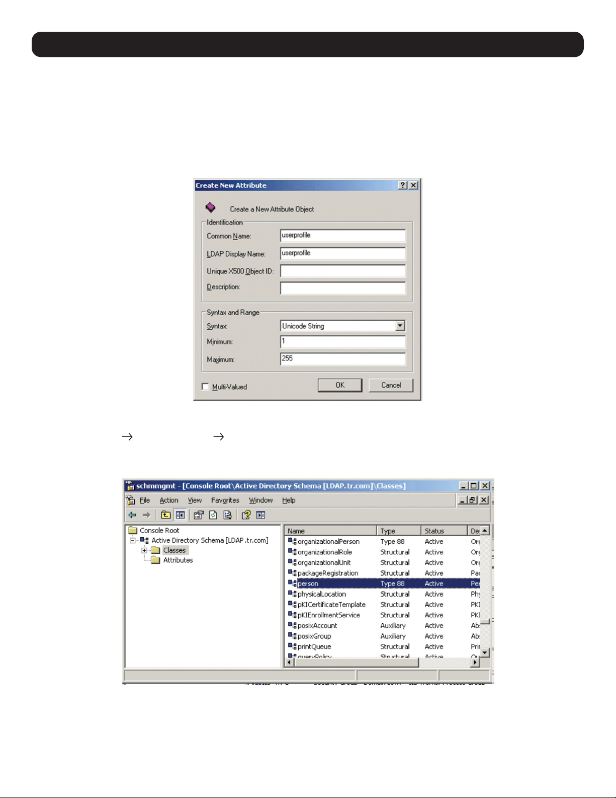
64
e) Fill in the dialog box according to the example below and click OK.
• Common Name – userprofile
• LDAP Display Name – userprofile
• Syntax – Unicode String
• Minimum – 1
• Maximum – 255
Note: The Unique X500 Object ID uses periods, not commas.
Step 2 - Extend the Object Class with the New Attribute:
a) Open Control Panel Administrative Tools Active Directory Schema.
b) In the left panel of the screen that appears, select Classes.
c) In the right panel, right-click on the user account name:
12. Network Settings
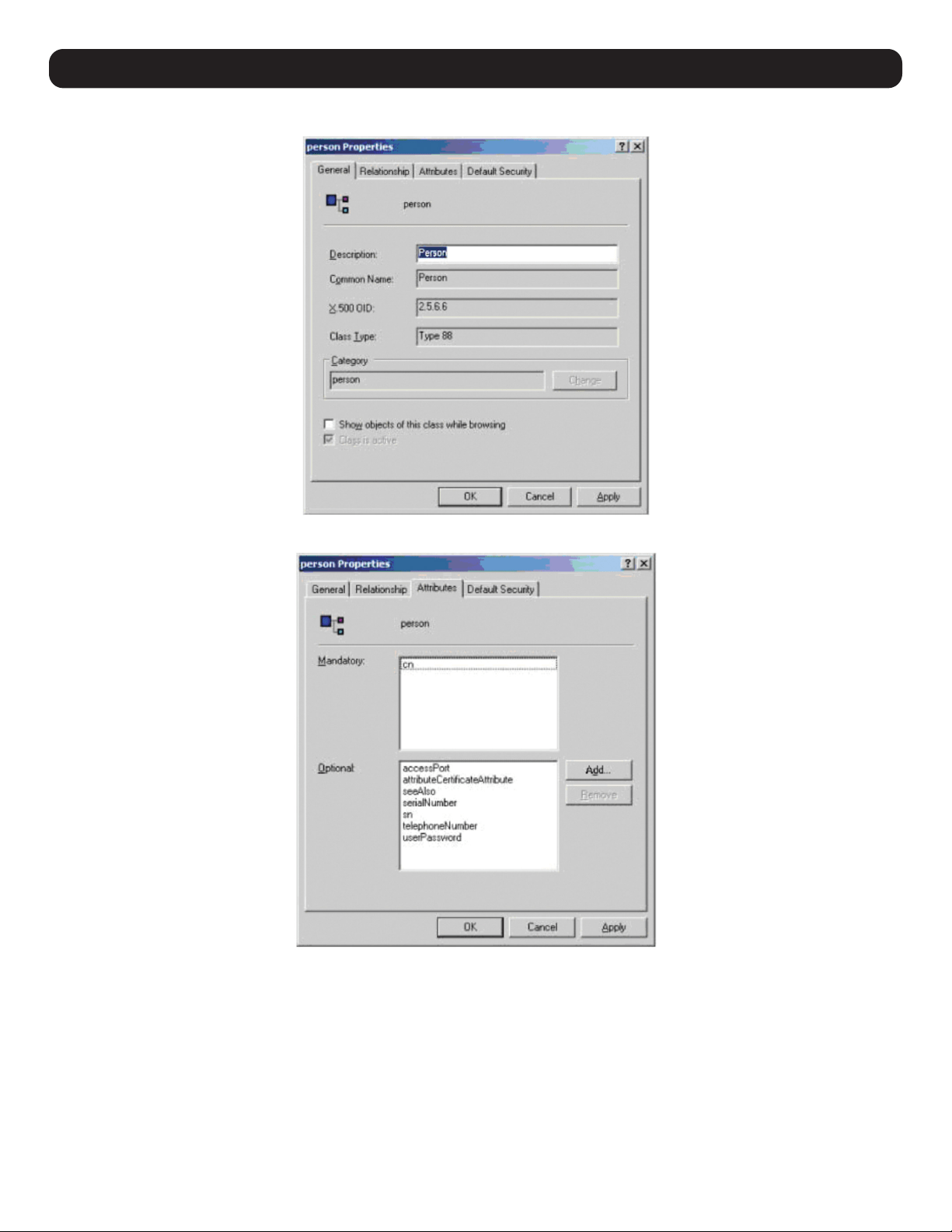
65
12. Network Settings
d) Select Properties; the user’s Properties page will appear with the General tab displayed.
e) Select the Attributes tab and click Add:
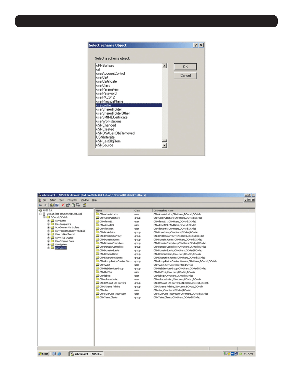
66
f) In the list that appears, select userprofile, then click OK.
Step 3 - Edit Active Directory Users with the Extended Schema:
a) Run ADSI Edit (installed as part of Support Tools.)
b) Open Domain and navigate to the cn=users dc=tripplite dc=com node.
c) Locate the user you wish to edit.
12. Network Settings
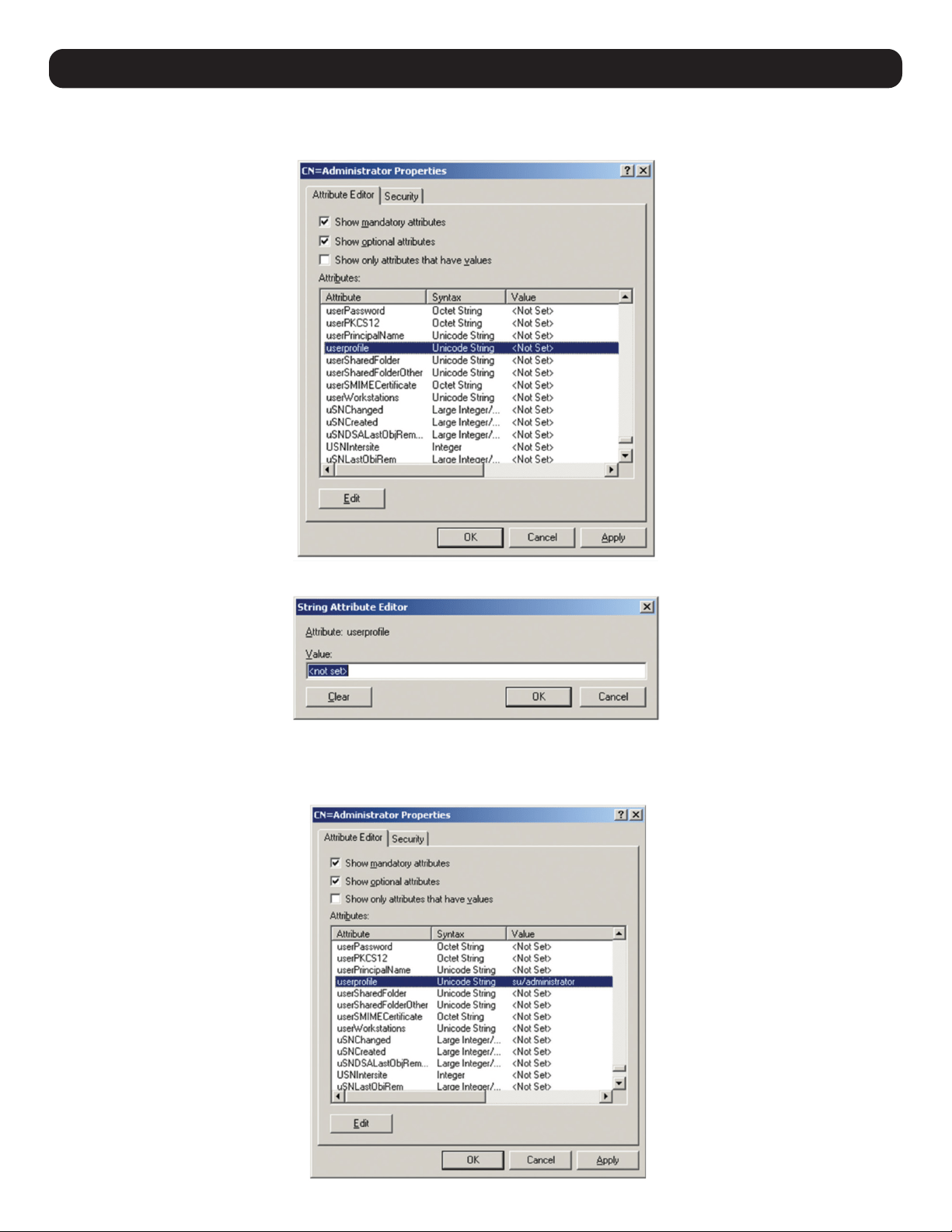
67
12. Network Settings
d) Right-click on the user’s name and select Properties.
e) On the Attribute Editor page of the dialog box that appears, select userprofile from the list.
f) Click Edit to access the String Attribute Editor:
g) Replace the value shown with su/xxxx, where xxxx represents the username assigned to the user in the KVM switch. User access rights will
be the same as those assigned to them in the KVM switch (refer to 12.1 User Management for details).
h) Click OK. When you return to the Attribute Editor page, the userprofile entry will reflect the new permissions:
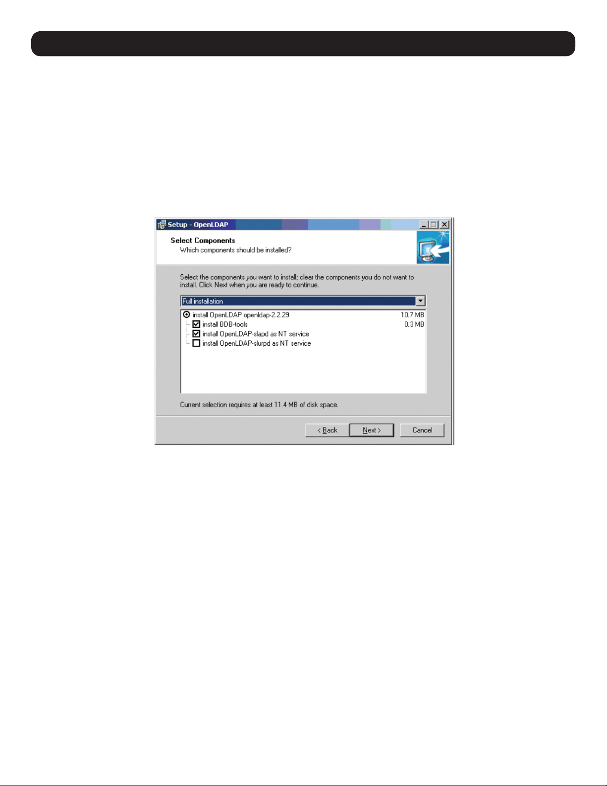
68
i) Click Apply to save the change and complete the procedure.
j) Repeat Step 3 (Edit Active Directory Users with the Extended Schema) to add any additional users.
12.3 OpenLDAP Server Installation
OpenLDAP is an open source LDAP server designed for UNIX platforms. A Windows version can be downloaded from:
http://download.bergmans.us/openldap/openldap-2.2.29/openldap-2.2.29-db-4.3.29-openssl-0.9.8awin32_Setup.exe.
After downloading the program, launch the installer, select your language, accept the license and choose the target installation directory.
The default directory is:
c:\Program Files\OpenLDAP.
When the Select Components dialog box appears, select install BDB-tools and install OpenLDAP-slapd as NT service:
12.3.1 OpenLDAP Server Configuration
The main OpenLDAP configuration file slapd.conf must be customized before launching the server. The modifications to the configuration file
will:
• Specify the Unicode data directory. The default is ./ucdata.
• Choose the required LDAP schemas. The core schema is mandatory.
• Configure the path for the OpenLDAP pid and args start-up files. The first contains the server pid, the second includes command line
arguments.
• Choose the database type. The default is bdb (Berkeley DB).
• Specify the server suffix. All entries in the directory will have this suffix, which represents the root of the directory tree. For example, with
suffix dc=tripplite,dc=com, the fully qualified name of all entries in the database will end with dc=tripplite,dc=com.
• Define the name of the administrator entry for the server (rootdn), along with its password (rootpw). This is the server’s super user. The
rootdn name must match the suffix defined above. Since all entry names must end with the defined suffix, and the rootdn is an entry.
12. Network Settings
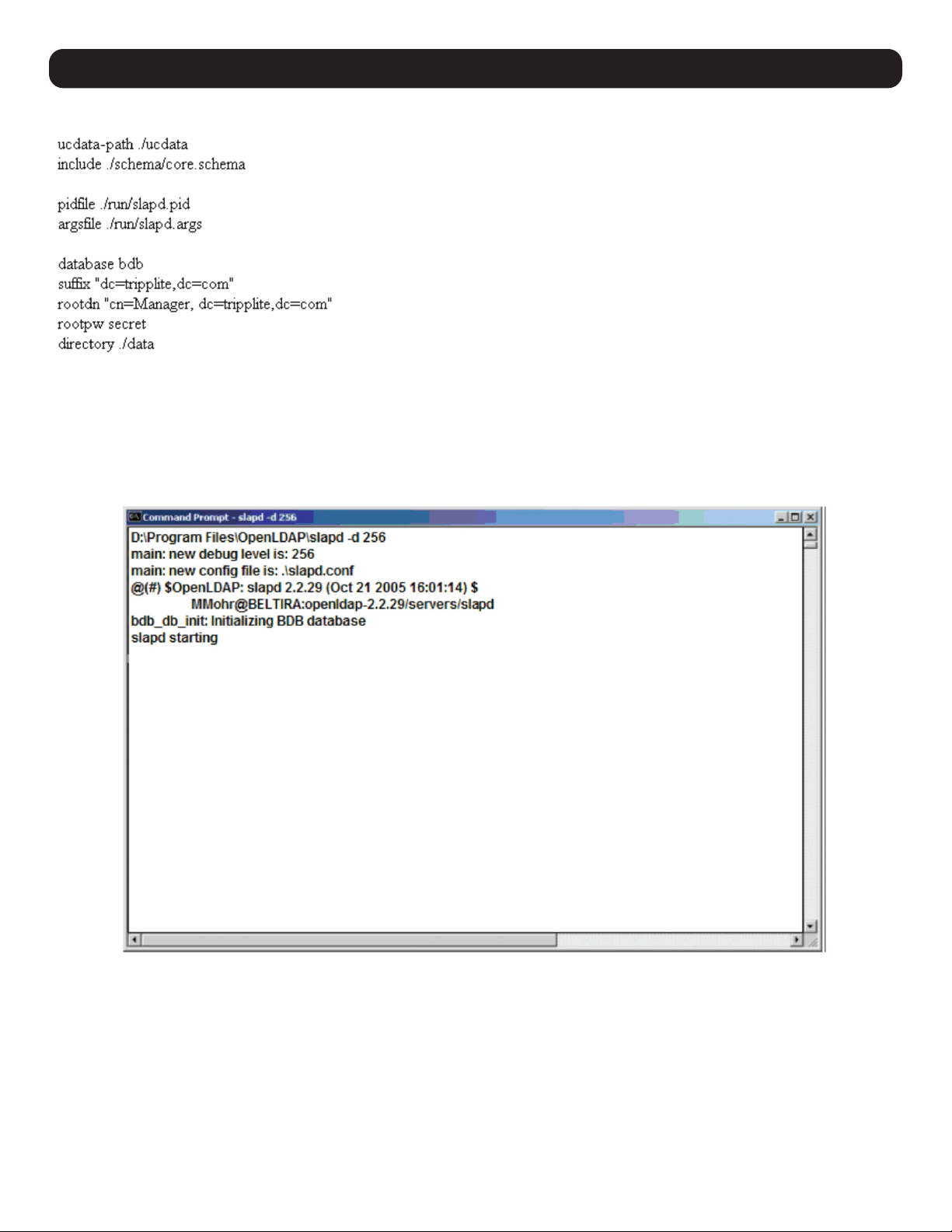
69
12. Network Settings
An example configuration file will appear as:
12.3.2 Starting the OpenLDAP Server
To start the OpenLDAP Server, run slapd (the OpenLDAP Server executable file) from the command line. slapd supports a number of command
line options, the most important option is the d switch that triggers debug information. For example, a command of slapd -d 256 would start
OpenLDAP with a debug level of 256, as shown in the following screenshot:
Note: For details about slapd options and their meanings, refer to the OpenLDAP documentation.
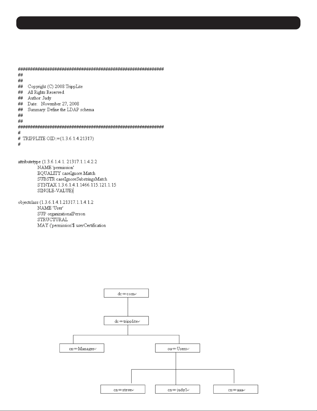
70
12.3.3 Customizing the OpenLDAP Schema
The schema that slapd uses may be extended to support additional syntaxes, matching rules, attribute types, and object classes. In the case
of the B030-008-17-IP, the User class and the permission attribute are extended to define a new schema. The extended schema file used to
authenticate and authorize users logging in to the KVM Switch is shown in the figure below:
12.4 LDAP DIT Design and LDIF File
12.4.1 LDAP Data Structure
An LDAP Directory stores information in a tree structure known as the Directory Information Tree (DIT). The nodes in the tree are directory
entries and each entry contains information in attribute-value form. An example of the LDAP directory tree for the B030-008-17-IP is shown in
the figure below:
12. Network Settings
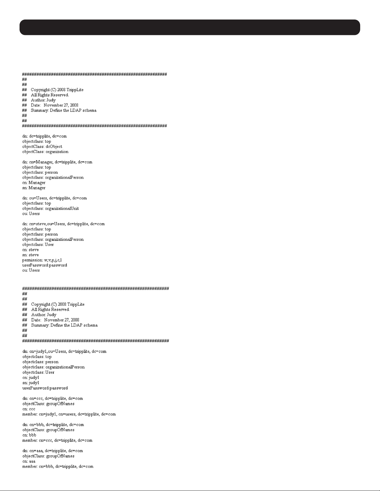
71
12. Network Settings
12.4.2 DIT Creation
The LDAP Data Interchange Format (LDIF) is used to represent LDAP entries in a simple text format (refer to RFC 2849). The figure below
illustrates an LDIF file that creates the DIT for the B030-008-17-IP directory tree (shown in the figure in the previous section).
The following figure illustrates an LDIF file that defines the OpenLDAP group for the B030-008-17-IP.
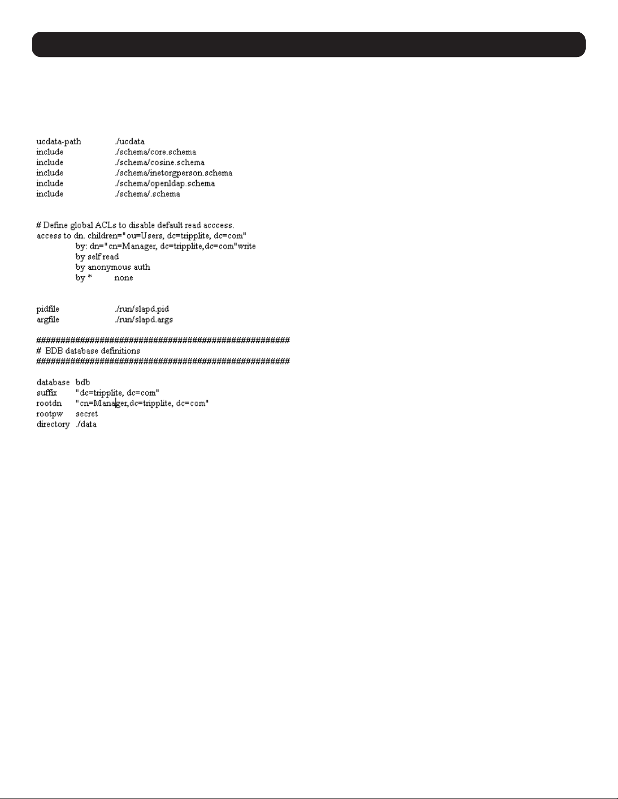
72
12.4.3 Using the New Schema
To use the new schema:
1. Save the new schema file (e.g., B030-008-17-IP.schema) in the /OpenLDAP/schema/ directory.
2. Add the new schema to the slapd.conf file, as shown in the figure below.
3. Restart the LDAP server.
4. Write the LDIF file and create the database entries in init.ldif with the ldapadd command. Example:
ldapadd -f init.ldif -x -D “cn=Manager,dc=tripplite,dc=com” -w secret
12. Network Settings
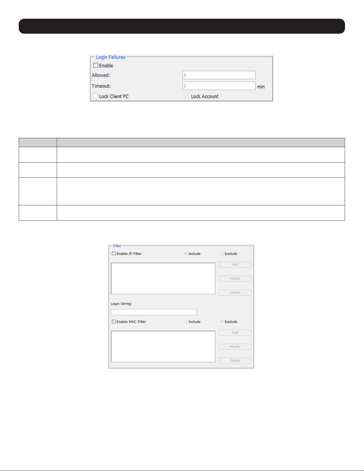
73
13. Security
13.1 Login Failures
The Login Failures section sets the parameters for when an account fails to login successfully. To enable settings, check the Enable box.
Settings are described in the table below.
Note: When the Login Failures settings are disabled, there is no restriction on the number of login failures. It is strongly recommended that these features are
enabled and both the Lock Client PC and Lock Account settings are also enabled.
Setting Description
Allowed Determines the number of failed login attempts an account is allowed before being prohibited from accessing the KVM
switch.
Timeout Determines the amount of time a user is prohibited from accessing the KVM switch after exceeding the maximum number
of failed login attempts.
Lock Client PC When this box is checked, the computer used to unsuccessfully access the KVM will be locked out after exceeding the
maximum number of failed login attempts.
Note: This feature blocks the computer by using its IP address. If the computer IP address is changed, it will be able to bypass this setting
and access the KVM.
Lock Account When this box is checked, the account used to unsuccessfully access the KVM will be locked out after exceeding the
maximum number of failed login attempts.
13.2 Filtering
To enable IP and/or MAC filtering, check the IP Filter Enable and/or MAC Filter Enable box. A maximum of 100 filters are allowed for each.
• If the Include button is checked, addresses within the filter range are allowed access to the B030-008-17-IP; all other addresses are denied
access.
• If the Exclude button is checked, addresses within the filter range are denied access to the B030-008-17-IP; all other addresses are allowed
access.
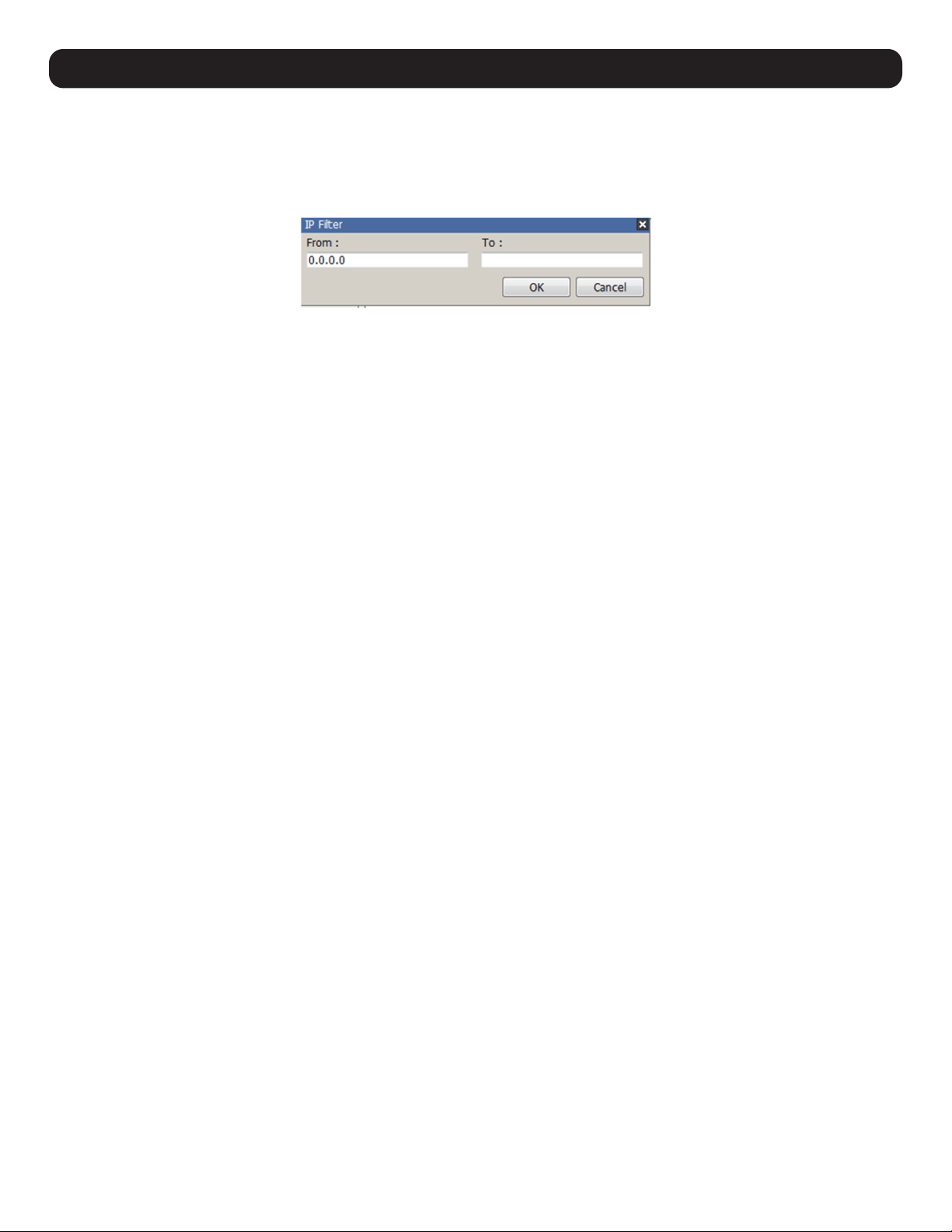
74
13. Security
13.2.1 IP Filtering
To add an IP filter:
1. Check the IP Filter Enable box.
2. Click Add. A dialog box will appear:
3. To filter a single IP address, enter the same IP address into the From and To fields.
4. To filter a range of IP addresses, enter the starting IP address in the From field and the ending IP address in the To field.
5. After entering in the addresses, click OK.
6. Repeat these steps for any additional IP addresses you want to filter.
To delete an IP filter:
Select the desired IP filter from the list and click Remove.
To modify an IP filter:
1. Select the desired IP filter from the list and click Edit. An Edit dialog box similar to the Add dialog box will appear.
2. Delete the old start IP address and replace it with the new one.
3. Delete the old end IP address and replace it with the new one. Click OK.
Note: To block a computer from accessing the KVM Switch, you do not need to filter both its IP address and its MAC address. Any computer blocked by an IP
filter will be denied access to the KVM switch, even if the computer is allowed to access the KVM switch under the MAC filters.
13.3 Login String
The Login String allows the KVMs IP address to be more secure by adding extra text to the end of it. When text is entered into the Login String
field, users will need to include a forward slash (/) and the Login String at the end of the URL to access the KVM switch. For example, if a Login
String of abcdefg is entered, the user must enter a URL such as 192.168.0.126/abcdefg.
The following characters are allowed in the login string:
0 through 9; a through z; A through Z; ~ ! @ $ & * ( ) _ - = +[ ] , . |
The following characters are not allowed:
% ^ ” : / ? # \ ‘ { } ; < > [Space]
Compound characters (É Ç ñ ... etc.)
Note: If a Login String is not entered, anyone can access the KVM switch using the IP Address alone, making the installation less secure.
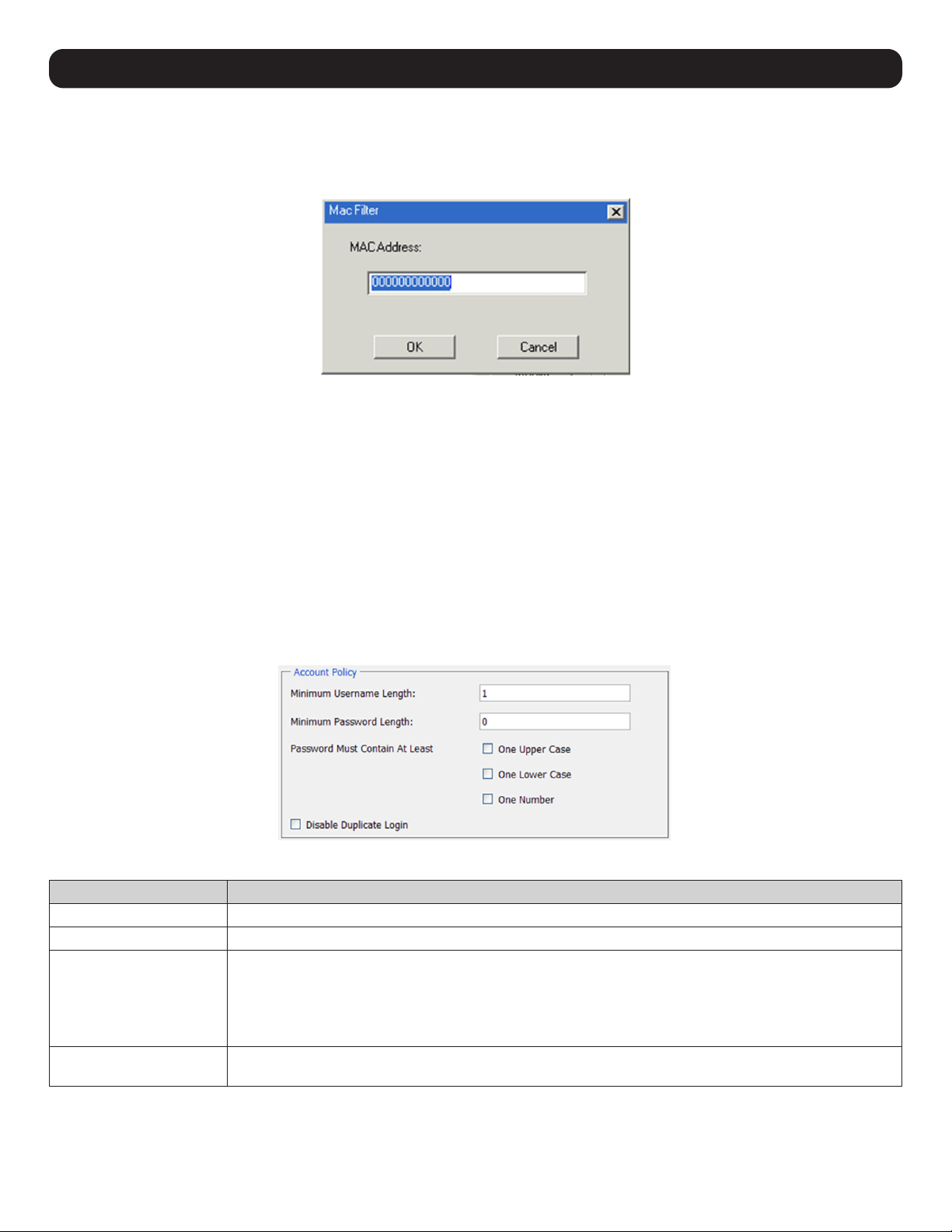
75
13.4 MAC Filtering
To add a MAC filter:
1. Click Add. A dialog box appears:
2. Type in the desired MAC address and click OK.
3. Repeat these steps for any additional MAC addresses to filter.
To delete a MAC filter:
Select the desired MAC filter from the list and click Remove.
To modify a MAC filter:
1. Select the desired MAC filter from the list and click Edit. An Edit dialog box will appear.
2. Delete the old address and replace it with the new one. Click OK.
Note: To block a computer from accessing the KVM Switch, you do not need to filter both its IP address and its MAC address. Any computer blocked by a MAC
filter will be denied access to the KVM switch, even if the computer is allowed to access the KVM switch under the IP filters that are set up.
13.5 Account Policy
The Account Policy subsection allows rules for usernames and passwords to be regulated. The settings are described in the table below.
Item Description
Minimum Username Length Sets the minimum number of characters required for each username. Values from 1 to 16 can be entered.
Minimum Password Length
Sets the minimum number of characters required for each password. Values from 0 to 16 can be entered.
Password Must Contain
at Least
• One Upper Case – Checking this box will require each password contain one upper case letter.
• One Lower Case – Checking this box will require each password contain one lower case letter.
• One Number – Checking this box will require each password contain one number.
Note: Current usernames and passwords are not affected when these settings are changed. Only usernames and passwords
that are created after these settings have been changed are bound by these regulations.
Disable Duplicate Login Checking this box will prevent users from logging in with the same username and password to open more than
one session at the same time.
13. Security
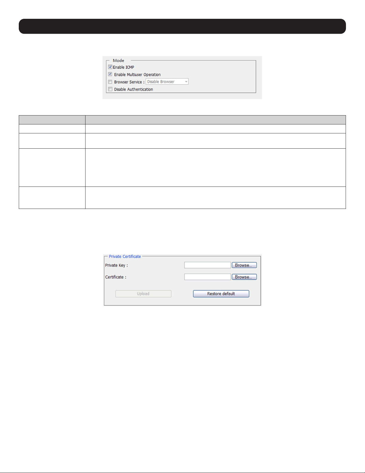
76
13. Security
13.6 Mode
The Mode operation settings are described in the table below.
Item Description
Enable ICMP When this box is checked, the KVM switch can be pinged. If it is not checked, the KVM cannot be pinged.
Enable Multiuser Operation When this box is checked, multiple accounts (up to 32) can remotely log on to the KVM at the same time.
If not selected, only one user can log on at a time. The default is enabled.
Browser Service When this box is checked, browser access to the KVM switch can be limited by selecting one of the three
options in the drop-down menu.
• Disable Browser – Browser access is completely disabled.
• Disable HTTP – Browser access is permitted, but only when using an HTTPS URL.
• Disable HTTPS – Browser access is permitted, but only when using an HTTP URL.
Disable Authentication When this box is checked, no authentication procedures are used to check accounts logging into the KVM.
All users will be logged onto the KVM switch with full access, regardless of what account type they are.
Note: Enabling this setting creates a very unsecure situation, and is not recommended.
13.7 Private Certificate
When logging into the KVM switch over a secure (SSL) connection, a certificate is required to ensure you are logging into a secure site. If a
certificate is not recognized as secure, you will be prompted each time you log in to verify you want to continue to the website. This section
allows you to import an Encryption Key and Certificate. To import an Encryption Key and Certificate, follow the steps below.
1. Click the Browse button to the right of Private Key, browse to where your private encryption key file is located, then select it.
2. Click the Browse button to the right of Certificate, browse to where your certificate file is located, and then select it.
3. Click the Upload button to complete the procedure.
Note: Both the Private Key and Certificate must be imported at the same time. Clicking the Restore Default button returns the KVM to the default certificate
preinstalled on it.
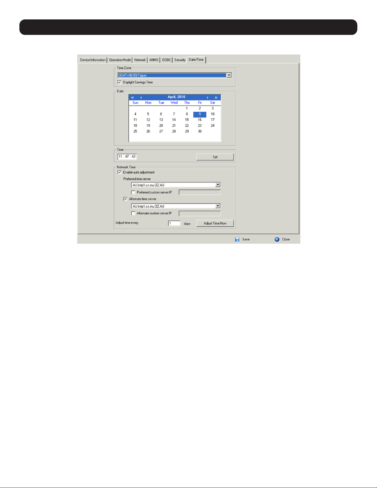
77
14. Date/Time
The Date/Time page sets the date and time parameters for the KVM switch.
14.1 Time Zone
• From the drop-down menu at the top of the section, select the Time Zone and City that most closely resembles where the KVM switch is
located.
• If your area uses Daylight Savings Time, check the Daylight Savings Time box.
To manually set the date and time:
1. In the Date section, select the current month from the drop-down menu.
2. If needed, click the < or > buttons in the Date section to move backward or forward to the correct year.
3. In the calendar in the Date section, click on the current day.
4. In the Time section, enter the current time using the 24 hour HH:MM:SS format.
5. Click the Set button in the Time section to apply changes.
14.2 Network Time
To have the time automatically synchronized to a network time server, do the following:
1. Check the Enable Auto Adjustment box.
2. Select a time server from the Preferred Time Server drop-down list or check the Preferred Custom Server IP box and enter the IP of your
preferred time server.
3. If desired, repeat step two to enter an Alternate Time Server.
4. Enter the desired number of days between synchronization in the Adjust Time Every __ Days field.
5. Click the Adjust Time Now button to synchronize immediately.
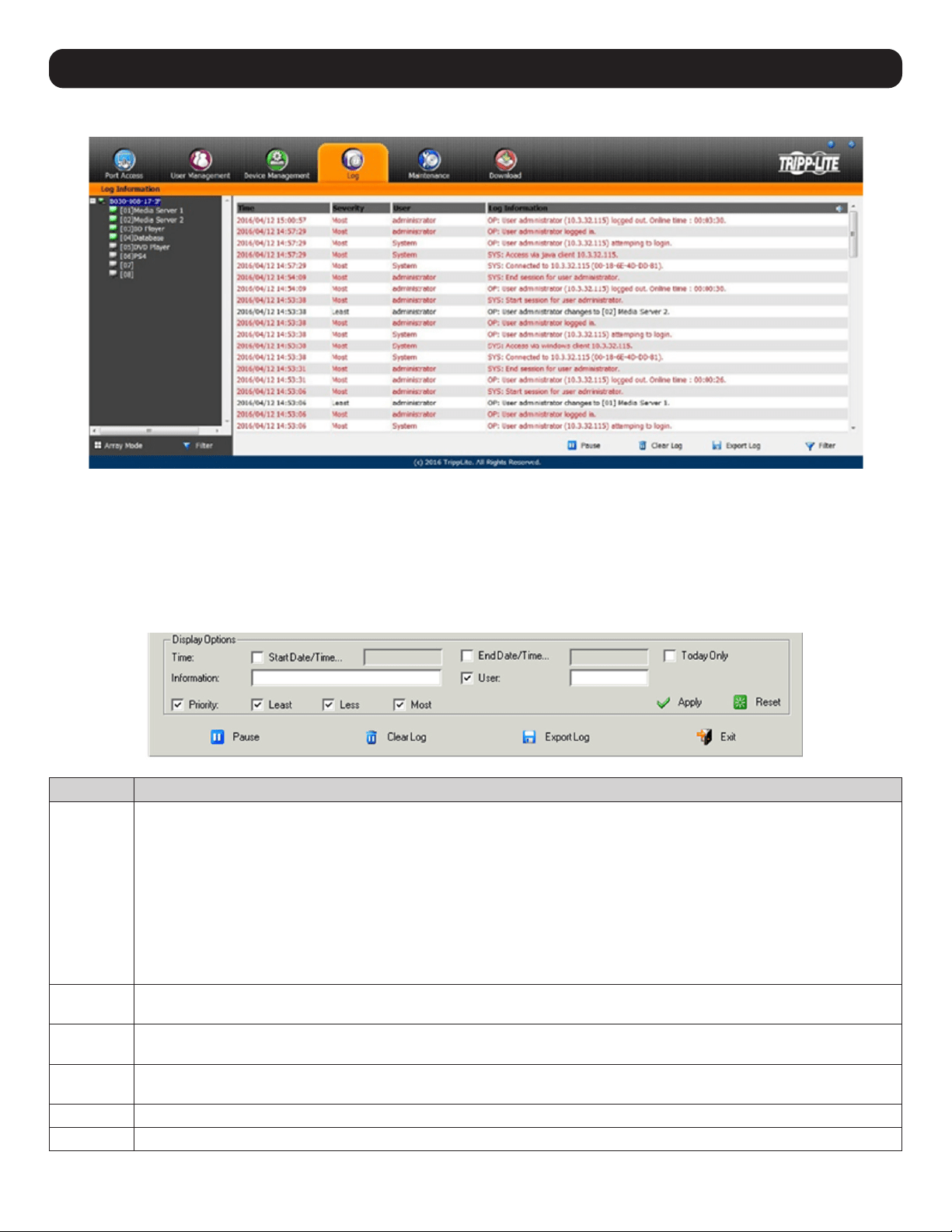
78
15. Log
The B030-008-17-IP logs all the events that occur and records them to a log file.
The Log Information page can store up to 512 events, at which time the oldest files are deleted and replaced with newer files. The records it
displays show the Time, Severity, User and Log Information associated with the event. Four icons are located at the bottom of the screen:
• Pause – Clicking the Pause button stops new events from being displayed in the Log Information page. When clicked, the icon changes to
Resume. Click Resume to allow events to be displayed again.
• Clear Log – Clicking the Clear Log button will clear the records displayed in the Log Information page.
• Export Log – Clicking the Export Log button exports and saves the log file to your computer.
• Filter – Clicking the Filter button opens the Filter settings (shown below) which displays records that only match the filter settings entered
Item Description
Time The Time filter settings displays only those records that occurred at a specific time. Options include:
• Today Only – Check the Today Only box and click the Apply button to display only those events that occurred on today’s date.
• Start Date/Time – Check the Start Date/Time box and click the field to the right of it to open a calendar to select a desired
date and time. Click the Apply button to display all events that occurred between the date/time entered into the Start Date/
Time field and the present date/time.
• End Date/Time – This setting works in conjunction with the Start Date/Time field. Check the Start Date/Time box and click
the field to the right of it to open a calendar that allows you to select a desired date and time. Check the End Date/Time box
and click in the field to the right of it to open a calendar that allows you to select a desired date and time. Click the Apply
button to display all of the events that occurred between the date/time entered into the Start Date/Time field and the date/
time entered into the End Date/Time field.
Information The Information field allows you to type in a key word or string, and display only those records that contain the search term.
Simply type in a search term and click the Apply button.
User The User field allows you to type in a user name and display only those records that contain the text that you entered in the
User field. To filter by User, check the User box, type in a search term and click the Apply button.
Priority The Priority fields filter the Priority of the event being recorded; Least, Less or Most. To filter by Priority, check the Priority box,
then check the Priority level box(es) to filter. Click the Apply button.
Reset Click the Reset button at any time to clear filter settings that were entered and display all events.
Exit Click the Exit button to close the Filter settings.

79
15. Log
Notification Settings
Notification Settings select which events are sent out to SNMP, SMTP and SysLog servers. Simply check the boxes in the rows of the events
that you want notifications for and check the column(s) of the methods you want them to be sent to. When checked, the corresponding event
notification will be sent using the corresponding method.
Note: Notifications default with an “X” to indicate they are disabled. Click on a notification box to enable it. You can check multiple boxes at the same time
using the [Shift] or [Ctrl] keys. To highlight a group of consecutive ports, start by highlighting the first port, hold down the [Shift] key, then highlight the last port
you wish to highlight. All ports from the first to the last will be highlighted. Click on any of the permission checkboxes to change that permission for all of the
highlighted ports. To highlight multiple non-consecutive ports, start by highlighting the first port, hold down the [Ctrl] key, then highlight each additional port while
continuing to hold down the [Ctrl] key. When all of the desired ports are highlighted, click on any box to change that permission for all of the highlighted ports.
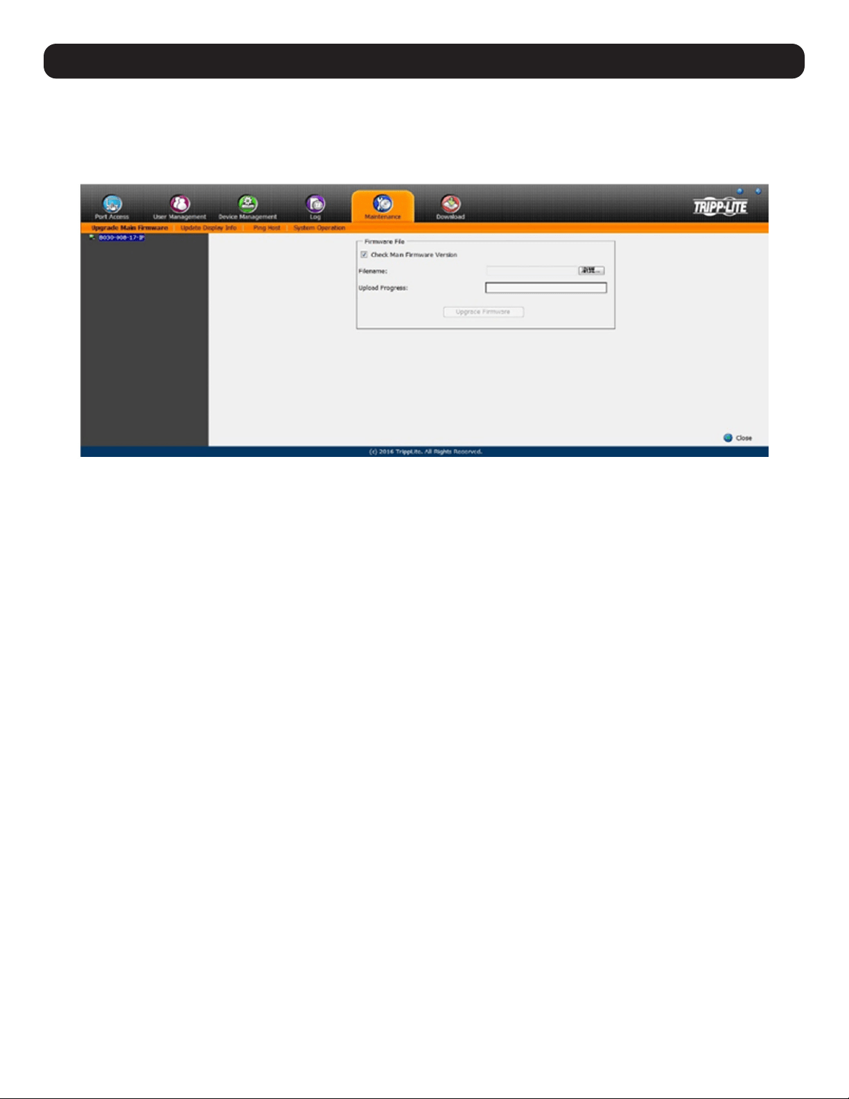
80
16. Maintenance
The Maintenance section is used to upgrade the B030-008-17-IP firmware, backup and restore configuration / account information, ping
network devices, and restore default values. When the Maintenance page is accessed, it will open with the Upgrade Main Firmware subsection
displayed.
Note: Super Administrators are the only users with guaranteed access to the Maintenance section of the KVM. Administrators and Users can only access this
function if given permission.
16.1 Upgrade Main Firmware
The Upgrade Main Firmware subsection is used to upgrade the firmware of the KVM switch. As firmware upgrades become available, they can
be downloaded from tripplite.com/support. To upgrade the KVM firmware:
1. Go to tripplite.com/support to download the most current firmware and save it to a computer that is not connected to the KVM switch.
2. Log on to the Web Interface and navigate to the Maintenance section, which will open with the Upgrade Main Firmware subsection
displayed.
3. By default, the Check Main Firmware Version box is checked, which causes the KVM to check if the current firmware is newer than the
firmware file being used to upgrade the KVM. If the current version is newer, you will not be allowed to continue with the upgrade. If
performing a firmware upgrade without checking to see if the current firmware version is newer than the upgrade file, simply uncheck this
box.
4. Click the Browse button, and navigate to and select the firmware upgrade file downloaded from the Tripp Lite website. When selected, the
Upgrade Firmware button becomes active.
5. Click the Upgrade Firmware button to begin the firmware upgrade. As the upgrade proceeds, progress is shown in the Upload Progress bar.
6. When the upload is complete, a popup appears stating the system will reboot in a few seconds. The KVM switch will reboot (this may take
a few minutes) and the upgrade will be complete. In the event of a firmware upgrade failure, see the Main Firmware Upgrade Recovery
section below.
16.1.1 Main Firmware Upgrade Recovery
Should the KVM firmware upgrade procedure fail and the switch becomes unusable, follow the steps below to restore the KVM:
1. Power off the KVM.
2. Press and hold the Reset switch on the front of the device.
3. Power on the KVM while holding down the Reset switch.
4. The KVM will be restored to the originally installed firmware version. You will now be able to access the KVM switch and try upgrading the
firmware again.
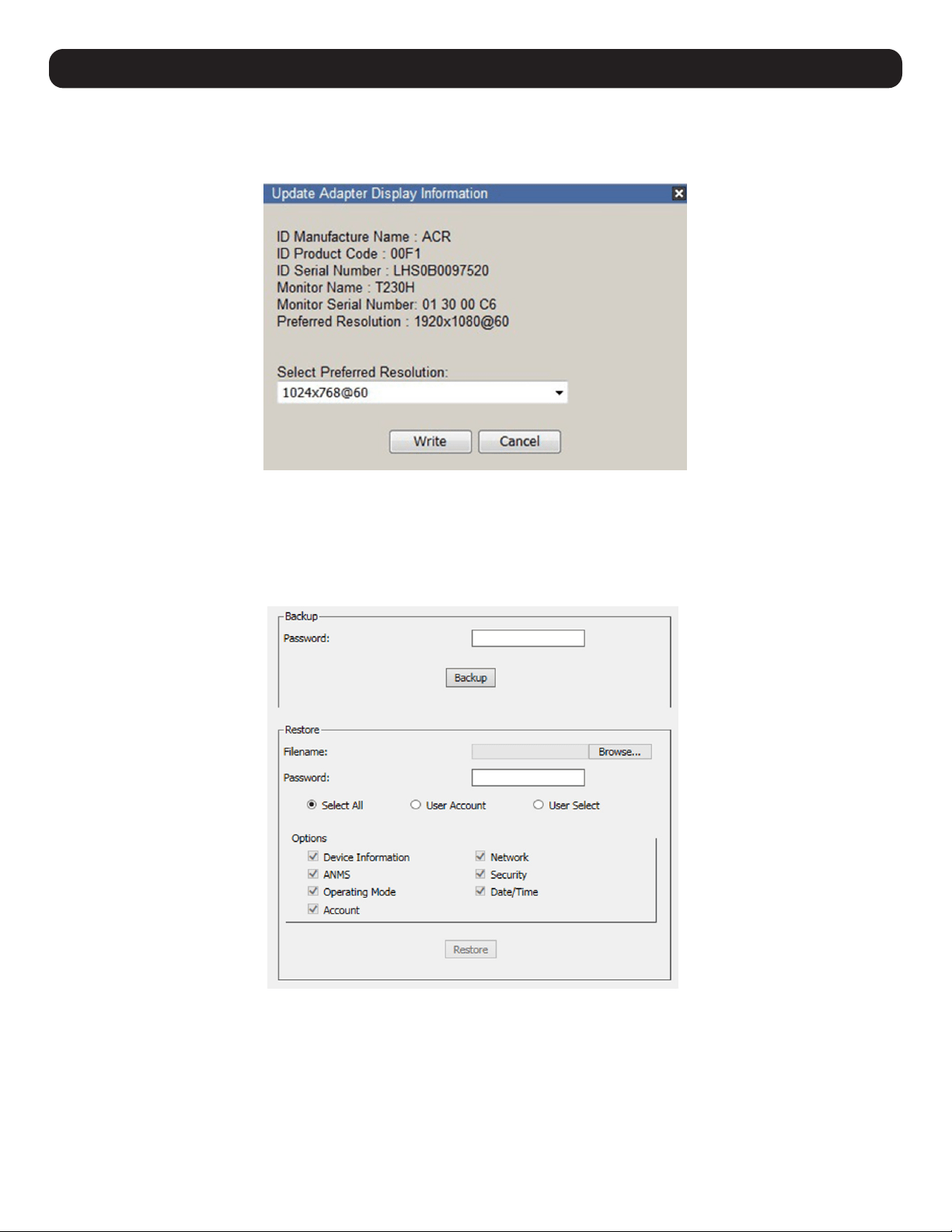
81
16. Maintenance
16.2 Update Display Info
The Update Display Info button queries the local monitor’s EDID information and updates it. The EDID information communicates with the
server’s video card about the display hardware it is connected to (e.g. the monitor connected to the KVM console).
The monitor’s Preferred Resolution (Optional) is included in the Display Information window. To apply the preferred resolution, select an option
from the Select Preferred Resolution drop down menu, then click Write.
16.3 Backup / Restore
The Backup/Restore function backs up and restores the KVM switch configuration and user profile information.
Backup
To create a backup of the KVM switch:
1. Enter a password in the Password field.
Note: Setting a password is optional. If you do not wish to use a password, you can skip this step.
2. Click the Backup button.
3. A pop-up will appear ask to save the backup file. Save the file to a desired location on your computer.
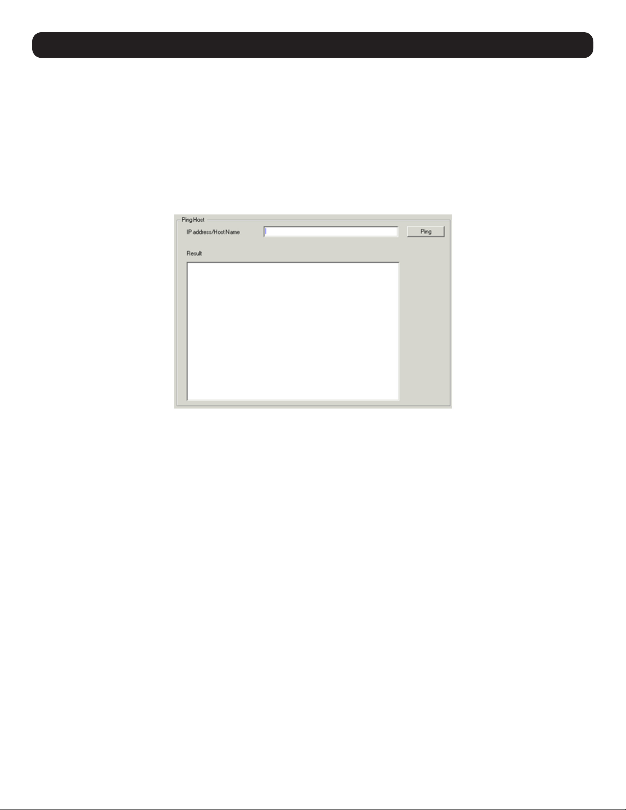
82
16. Maintenance
Restore
To restore the KVM switch using a backup file:
1. Click on the Browse button to the right of the filename field and select the backup file.
2. If you set up a password when creating the backup file, enter it in the Password field.
3. Select as many options you wish to restore, then click the Restore button. Once complete, a message will appear stating the procedure
succeeded.
16.4 Ping
The Ping menu item checks the network status of devices on the B030-008-17-IP installation:
To ping a device:
1. Enter the device’s IP Address or Host Name into the text entry box.
2. Click Ping. The ping results display in the Result panel.
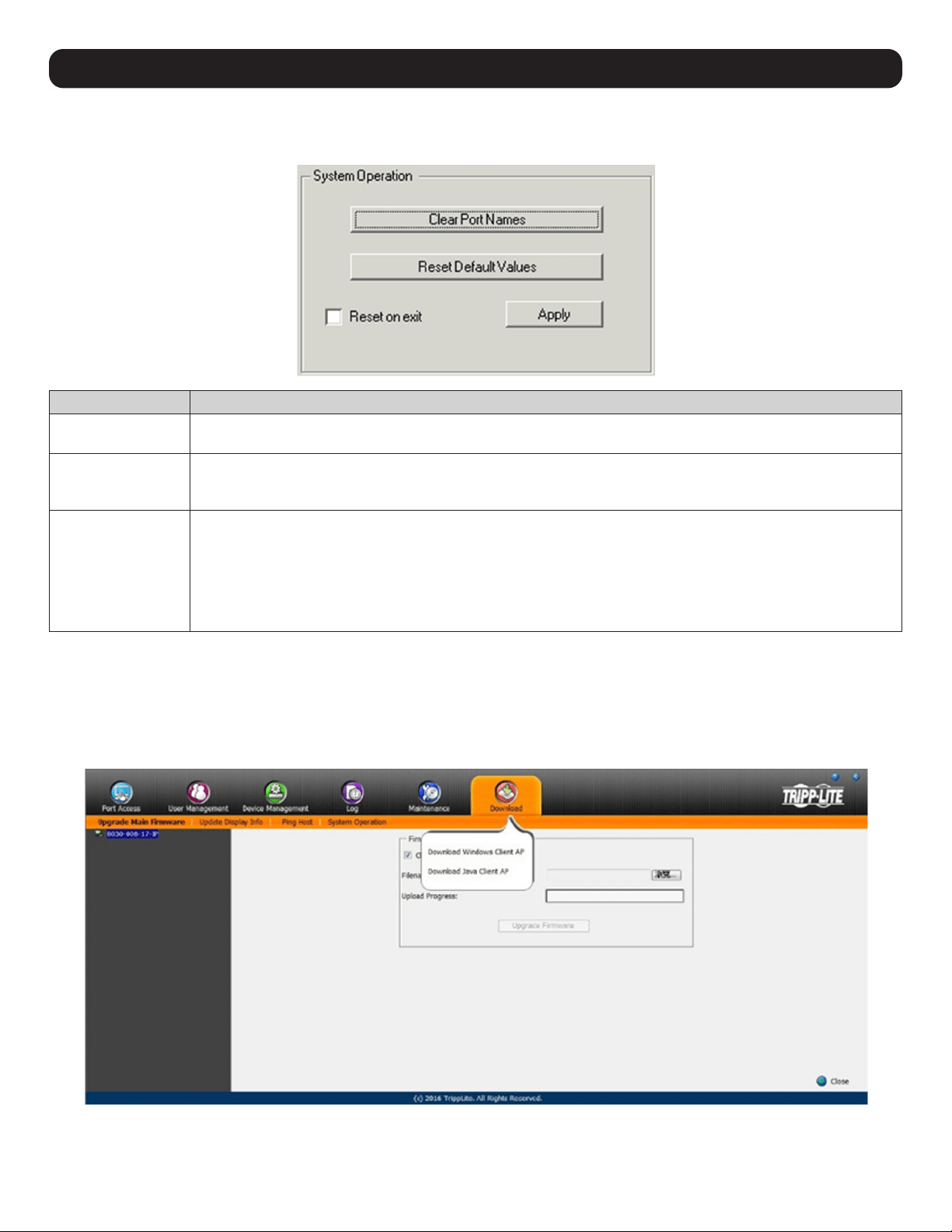
83
16. Maintenance
16.5 System Operation
The System Operation subsection clears port name and resets the KVM configuration settings to their default values.
Item Description
Clear Port Names Click this button to clear all port names on the installation and restore to their default values. Upon clicking this but-
ton, a prompt will appear to confirm that you wish to clear all port names. Click Yes.
Reset Default Values Click this button to undo all Customization page changes that have been made, as well as the Network Transfer Rate
setting, and restore them to the factory default settings. Upon clicking this button, a prompt will appear to confirm
that you wish to proceed. Click Yes.
Reset on Exit Check this box and click the Apply button for the KVM switch to reset and implement new settings upon logging out
(following the reset, allow approximately 30 to 60 seconds before logging back into the KVM). If the KVM’s IP ad-
dress is changed, the Reset on Exit box is automatically checked. To prevent the KVM from resetting and saving the
new IP address, uncheck this box.
Note: Un-selecting this box will only cause the new network settings to be ignored for one logout. When re-logging in, the changes
made still appear in the Network settings fields and the Reset on Exit box is once again checked. To avoid unwanted changes to
settings, always ensure that the Network Settings page contains the correct information entered in.
16.6 Download
The Download icon is used to download the log server and non-browser AP versions of Windows and Java Clients. Selecting this tab will open a
drop-down list of the programs available for download.
Note: If you have not been given access to one of these applications, you will not be able to download it. Click on the Download icon and select the program.
Save the file to a convenient location on your hard disk run the program from there.
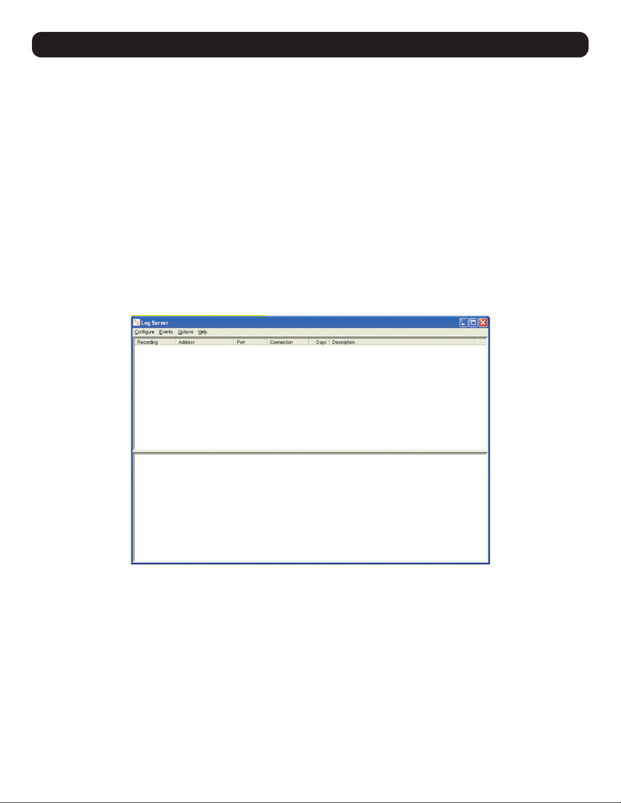
84
17. Log Server
The Windows-based Log Server is an administrative utility that records all the events on selected B030-Series KVM Switch units and writes
them to a searchable database.
17.1 Installation
1. From the computer designated as the Log Server, open the browser and log in to the KVM Switch.
2. Download the Log Server by clicking on the Download Icon at the top of the page and selecting it from the drop-down list.
3. Navigate to where the Log Server file is saved and double-click to open. Ignore any security warning dialog boxes that appear and click Run
or Open. The Log Server installation screen will appear.
4. Click Next. Then follow the onscreen instructions to complete the installation and have the Log Server program icon showing on the
desktop.
5. Before opening the Log Server, go to the Device Management section of the KVM switch web interface and open the ANMS tab. In the
corresponding fields, enter the MAC Address and Port Number for the computer/server that the Log Server is installed on (refer to 12.1
Advanced Network Management Settings for more information).
17.2 Opening the Log Server
To open the Log Server, either double-click the program icon or enter the full path to the program on the command line. The first time the
program is run, a screen as shown below will appear:
Note: The Log Server requires the Microsoft Jet OLEDB 4.0 driver in order to access the database.
The screen is divided into three components:
• A Menu Bar at the top
• A panel that will contain a list of all B030-Series KVM Switch units in the middle
• A panel that will contain an Events List at the bottom
17.3 Menu Bar
The Menu bar consists of four drop-down menus:
• Configure
• Events
• Options
• Help
Note: If the Menu Bar appears to be disabled, select one of the KVM units from the list window to enable.
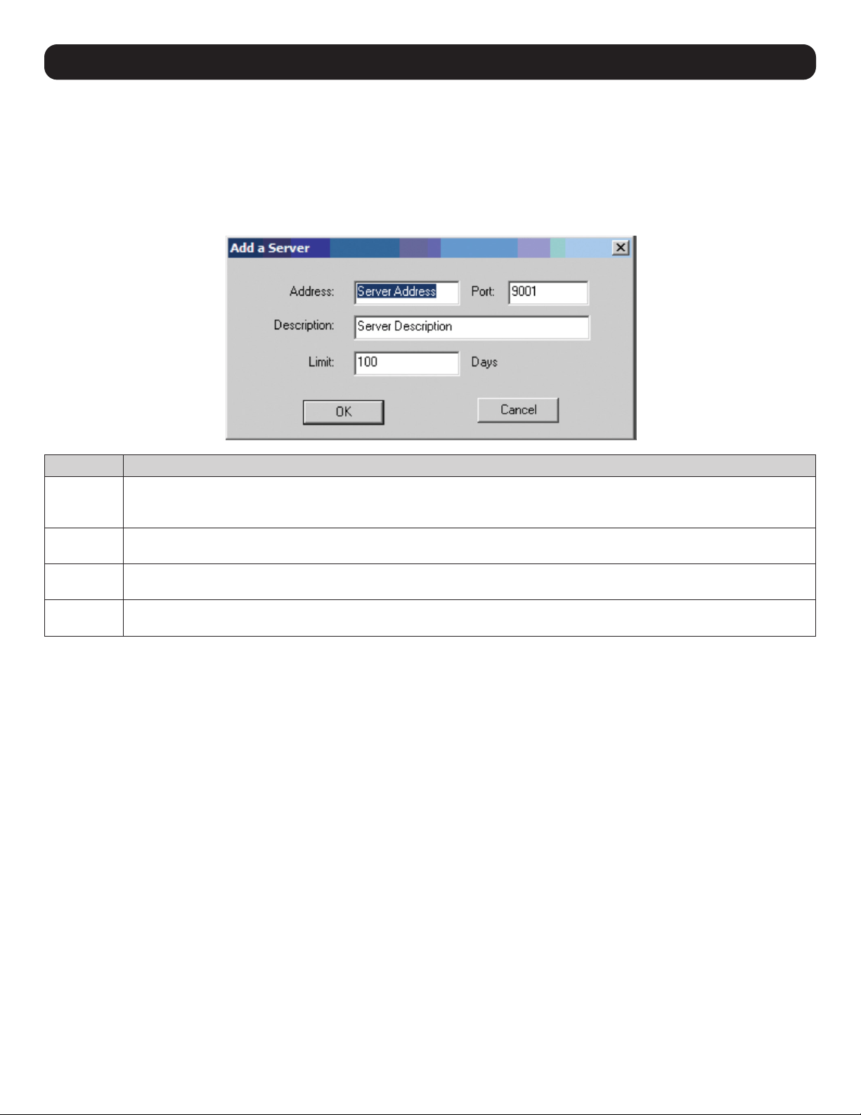
85
17. Log Server
17.3.1 Configure
The Configure menu consists of three functions: Add, Edit and Delete.
Add
Select the Add function when adding a new KVM switch to the list of units the Log Server records events for.
Note: First add a KVM via the Add function before the Log Server can start recording its events.
When opening the Add function, the following dialog box will appear (function descriptions can be found in the table below):
Field Description
Address This can either be the KVM’s IP address or its DNS name (if the network administrator has assigned it a DNS name). This
value must be entered into the ANMS tab of the OSD Device Management Notebook to communicate with the Log Server
(refer to 12.1 Advanced Network Management Settings for more information).
Port Enter the port number specified in the ANMS tab of the OSD Device Management Notebook. If the port number differs
between the KVM’s web interface and the Log Server, the two will not be able to communicate with each other.
Description Additional information can be added in this field to help differentiate the KVM from the rest of the devices the Log Server is
recording information for.
Limit Specifies the number of days an event is kept in the Log Server’s database before it can be deleted. To remove all events that
passed the expiration date set in this field, use the Maintenance function in the Events menu.
17.3.2 Edit
Select the Edit function to modify the information pertaining to an existing KVM. To edit an existing KVM, select it from the list and open the
Edit function from the Configure drop-down menu. A dialog box will appear showing the exact information that was entered for the KVM when it
was added using the Add function. Edit this information and click OK.
17.3.3 Delete
To delete a KVM, simply select it from the list and open the Delete function. A dialog box will appear displaying the KVM’s information and
requesting to click OK to delete it. To remove it from the Log Server, click OK.
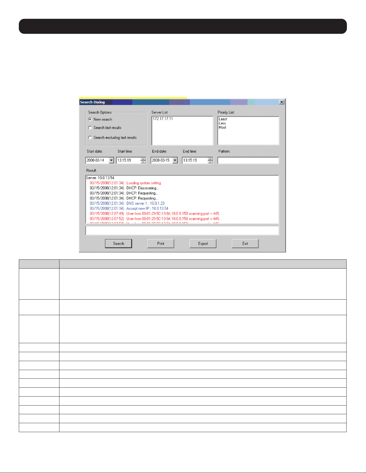
86
17. Log Server
17.4 Events
The Events Menu consists of two items: Search and Maintenance.
17.4.1 Search
Search allows users to search for events containing specific words or strings. When accessing this function, a window will open (item
descriptions can be found in the table below):
Item Description
Search Options
New search: When selected, the search is performed on all the events in the database for the selected KVM.
Search last results: This is a secondary search performed on the events that resulted from the last search.
Search excluding last results: This is a secondary search performed on all the events in the database for the selected
KVM, excluding the events that resulted from the last search.
Server List KVM units are listed according to their IP address. Select the unit from this list to perform a search. More than one unit
can be selected for the search. If no units are selected, the search is performed on all KVMs.
Priority List Sets the level for how detailed the search results displayed should be. If no results are selected, all results will display. If
all results display, entries highlighted red are of high or most important to installation security; entries highlighted blue are
of medium or less important to installation security; and entries highlighted black are of least importance to installation
security.
Start Date Select the date you wish the search to start from. The format follows the MM/DD/YYYY convention (e.g. 11/15/2009).
Start Time Select the time you wish the search to start from.
End Date Select the date you wish the search to end at. The format follows the MM/DD/YYYY convention (e.g. 11/15/2009).
End Time Select the time you want the search to end.
Pattern Enter text you wish the search to filter the events by.
Results The events that matched the search terms are listed here.
Search After entering all of search terms, click this button to start the search.
Print Prints the search results.
Export Export Log Server search results as a text file.
Exit Exits the Search dialog box.
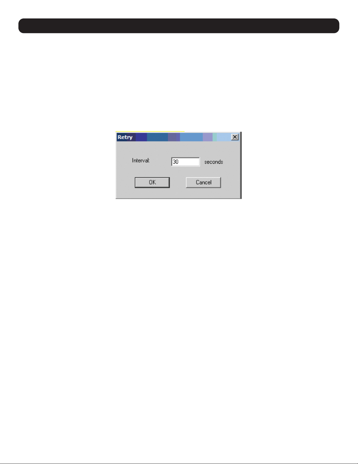
87
17.5 Maintenance
This function allows the administrator to remove all records that have passed their expiration limit (refer to 17.3.1 Configure for limit details).
In order to delete old files from the log server, the maintenance function must be performed.
17.6 Options
The Options menu consists of only one function: Network Retry.
17.6.1 Network Retry
Network Retry sets the number of seconds the Log Server should wait before attempting to connect if the previous connection attempt failed.
When clicking this item, a dialog box will appear:
Enter the desired number of seconds and click OK to finish.
17.7 Help
The Help menu consists of two options; Contents and About Log Server.
17.7.1 Contents
Selecting the Contents function opens an online Windows Help file. The Help file contains instructions on how to set up, operate and
troubleshoot the Log Server.
17.7.2 About Log Server
Selecting the About Log Server option opens a dialog box displaying the Log Server’s version number.
17. Log Server
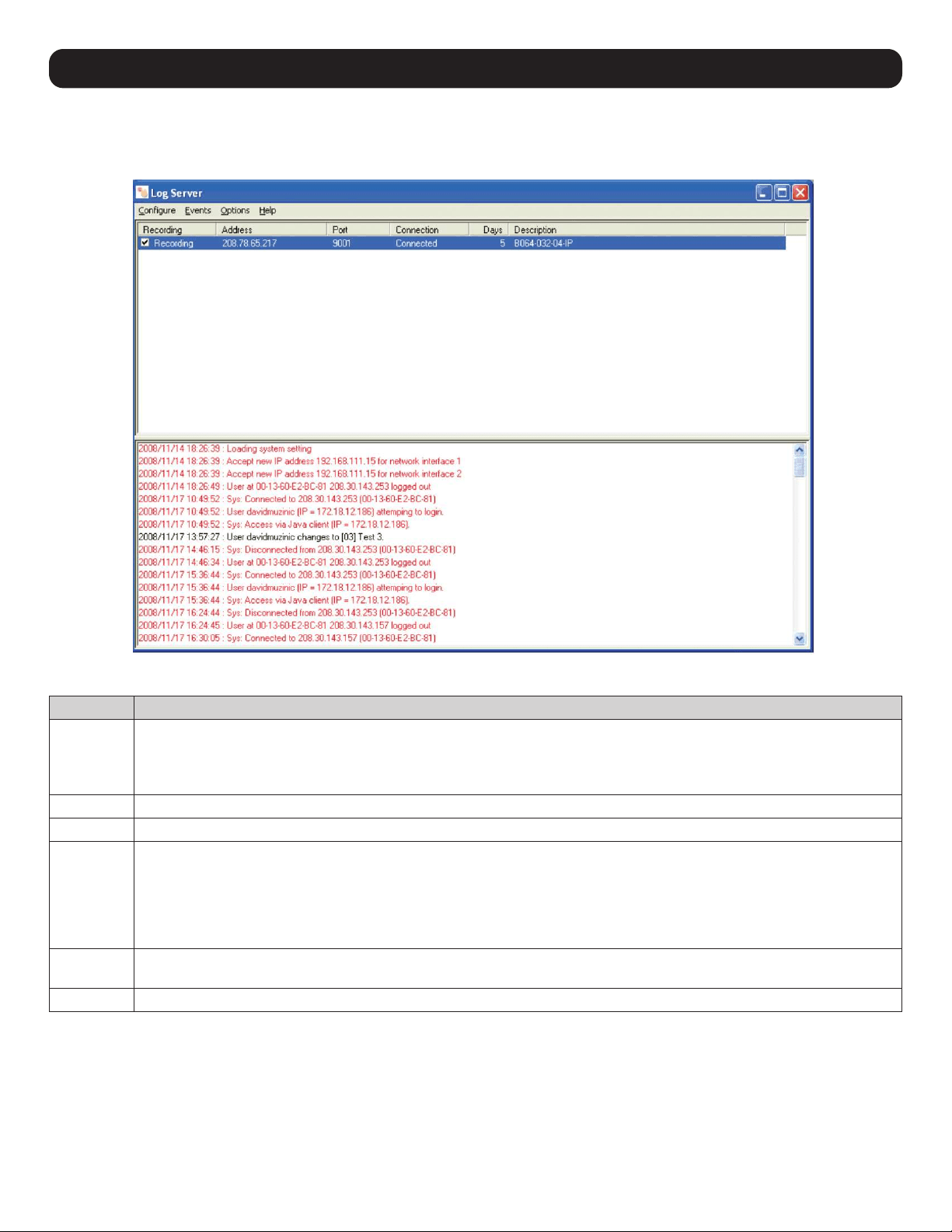
88
17. Log Server
17.8 Log Server Main Screen
The Log Server Main Screen is divided into two main panels: an upper (List) panel displaying all devices added to the Log Server and a lower
(Event) panel displaying log events for the currently selected KVM. To select a KVM unit in the list, simply click on it.
List Panel Fields
Field Description
Recording Determines whether the Log Server records log events for the corresponding KVM. If the Recording box is checked, the field
displays Recording, and log events are recorded. If the Recording box is not checked, the field displays Paused, and log events
are not recorded.
Note: Even if a KVM is not currently selected, if its Recording box is checked, the Log Server will continue to record its log events.
Address This is the IP Address or DNS name given to the KVM when it was added to the Log Server.
Port This is the port number assigned to the KVM when it was added to the Log Server.
Connection If the Log Server is properly connected to the KVM, this field displays Connected. If it is not connected, this field displays Wait-
ing. In effect, the Log Server is not communicating with KVM and will not record its events. This occurs when the Log Server’s
MAC address and/or port number have not been set properly. The MAC Address and Port for the Log Server computer must
be entered into the ANMS tab of the OSD Device Management Section. In addition, the KVM’s IP Address and Port must be
entered when adding it to the Log Server. If the KVM’s and Log Server’s port numbers do not match, they will not be able to
communicate.
Days Displays the number of days the KVM’s log events are to be kept in the Log Server’s database before they are eligible for
deletion.
Description Displays the descriptive information given for the KVM when it was added to the Log Server.
Event Panel
The lower panel displays event information for the currently selected KVM.
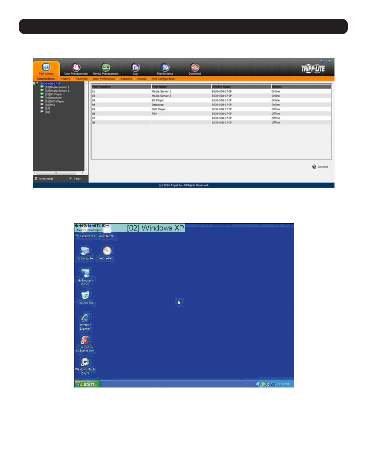
89
18. Remote Session Operation
After successfully logging in (see 10. Logging in to the KVM over IP for more information), the Web Interface Main Page will appear with the
Port Access tab selected:
All ports that a user is permitted to access are listed on the left of the Port Selection panel. Ports that users do not have access to will not
be displayed. Double-click a port icon to access the attached device. Once a user switches to a port, its screen will display on their monitor.
Whether a user has Full Access or View Only access to the port will determine if the user is able to operate the remote computer using their
keyboard and mouse.
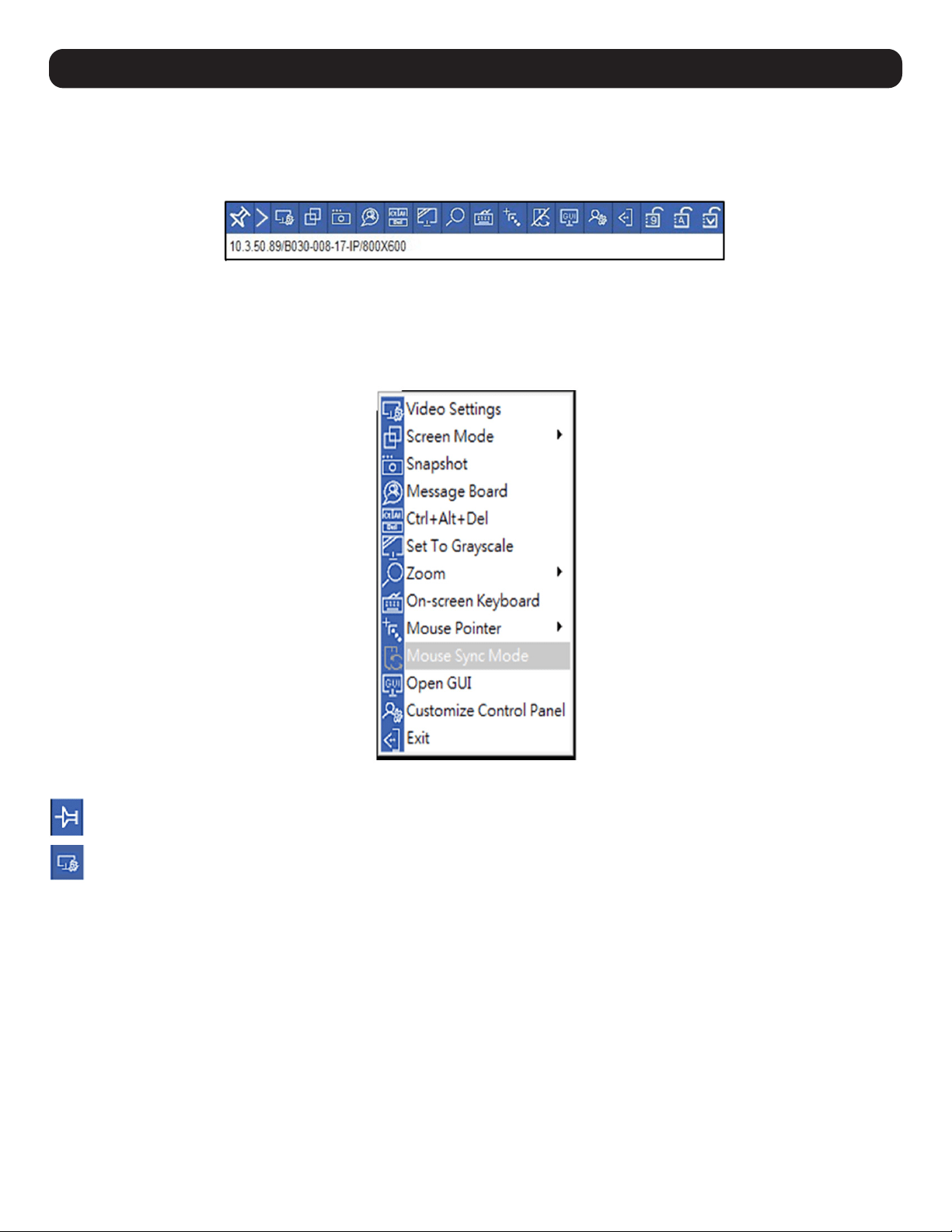
90
18. Remote Session Operation
18.1 Control Panel
The Control Panel is a way for the user to optimize and control the remote session. Regardless of whether the user initiated a remote session
via the Windows or Java browser and non-browser clients, the control panel and its functionality remain the same. To display the Control Panel,
hover the mouse pointer over the top-center of the remote screen.
The Control Panel consists of an icon bar situated above two text bars. When the mouse pointer is hovered over an icon, the icon description is
displayed in the text bar. When the mouse pointer is not over an icon, the text bars display the video resolution of the selected computer and
the IP address of the KVM switch. The control panel can be dragged to any location on the remote screen by hovering over the text bar and
then clicking and moving it to the desired desktop location.
Right clicking in the text bars initiates a menu-style version of the toolbar. In addition, it allows the user to select options for the Zoom, Mouse
Pointer, and Mouse Sync Mode.
The Control Panel icons are explained in greater detail below:
Always on Top / Auto Hide – Click this button to toggle between displaying the control panel all of the time or allowing it to disappear
after a few seconds of inactivity.
Video Settings – The Video Settings screen adjusts the placement and picture quality of the remote screen. The image display quality
has a direct effect on the keyboard and mouse response time. Higher quality video results in more information being transferred over
the network, which can cause slow keyboard and mouse response time in slower networks. Click this icon to open the Video Settings
screen or right-click on to perform an Auto Sync.
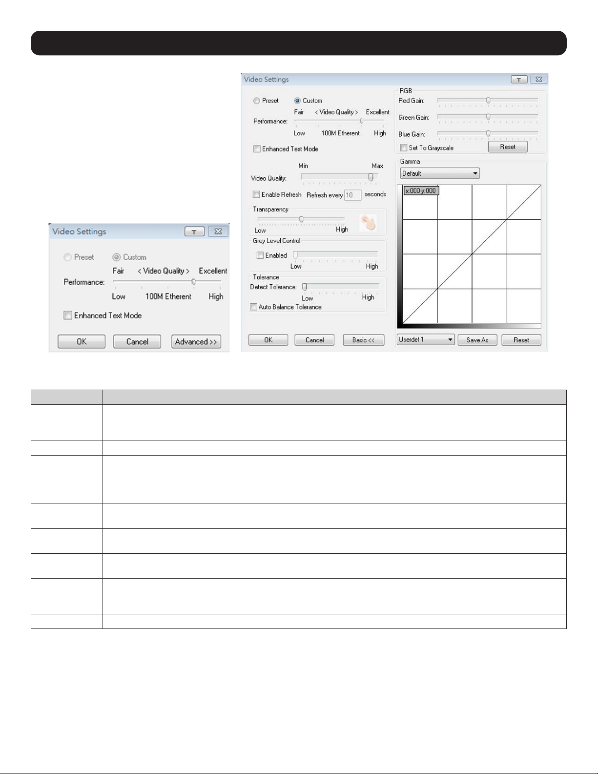
91
Video Adjustment Options
Option Usage
RGB Move the RGB (Red, Green, Blue) slider bars to adjust the corresponding color component of the video image. Check
the Set to Grayscale box to display the video of the remote computer without color. If the remote keyboard and mouse
response time is slow or choppy, the Set to Grayscale option can speed it up.
Gamma
Adjusts the video display’s gamma level. This function is discussed in greater detail in the Gamma Adjustment section.
Performance Use the slide bar to select the type of internet connection the local client computer uses. The switch will use that
selection to automatically adjust the Video Quality and Detect Tolerance settings to optimize the video display quality.
Because network conditions vary, if none of the pre-set choices appear to work well, use the Video Quality and Detect
Tolerance slider bars to adjust the settings to suit your conditions.
Video Quality Drag the slider bar to adjust the remote computer’s overall video quality. On slower networks, lowering the video quality
can help improve keyboard and mouse response time.
Enable Refresh The remote screen can be set to be redrawn every 1 to 99 seconds, which eliminates unwanted artifacts that would
otherwise remain on the screen. Click the Enable Refresh box to activate this feature, then enter the desired refresh rate.
Transparency Adjusts the transparency of the Remote Session Toolbar displayed when the [Scroll Lock] [Scroll Lock] hotkey is initiated
in a remote session. Move the slider bar until the transparency is set to the desired level.
Detect Tolerance This setting governs allowable pixel changes. A high setting limits changes, resulting in lower video quality and less
data transfer. A low setting allows more changes, resulting in higher video quality and greater data transfer. On slower
networks, a high detect tolerance setting can help improve keyboard and mouse response time.
Preset / Custom The Preset and Custom buttons set and save custom video settings, and revert to default video settings.
18. Remote Session Operation
Basic Video Settings Advanced Video Settings
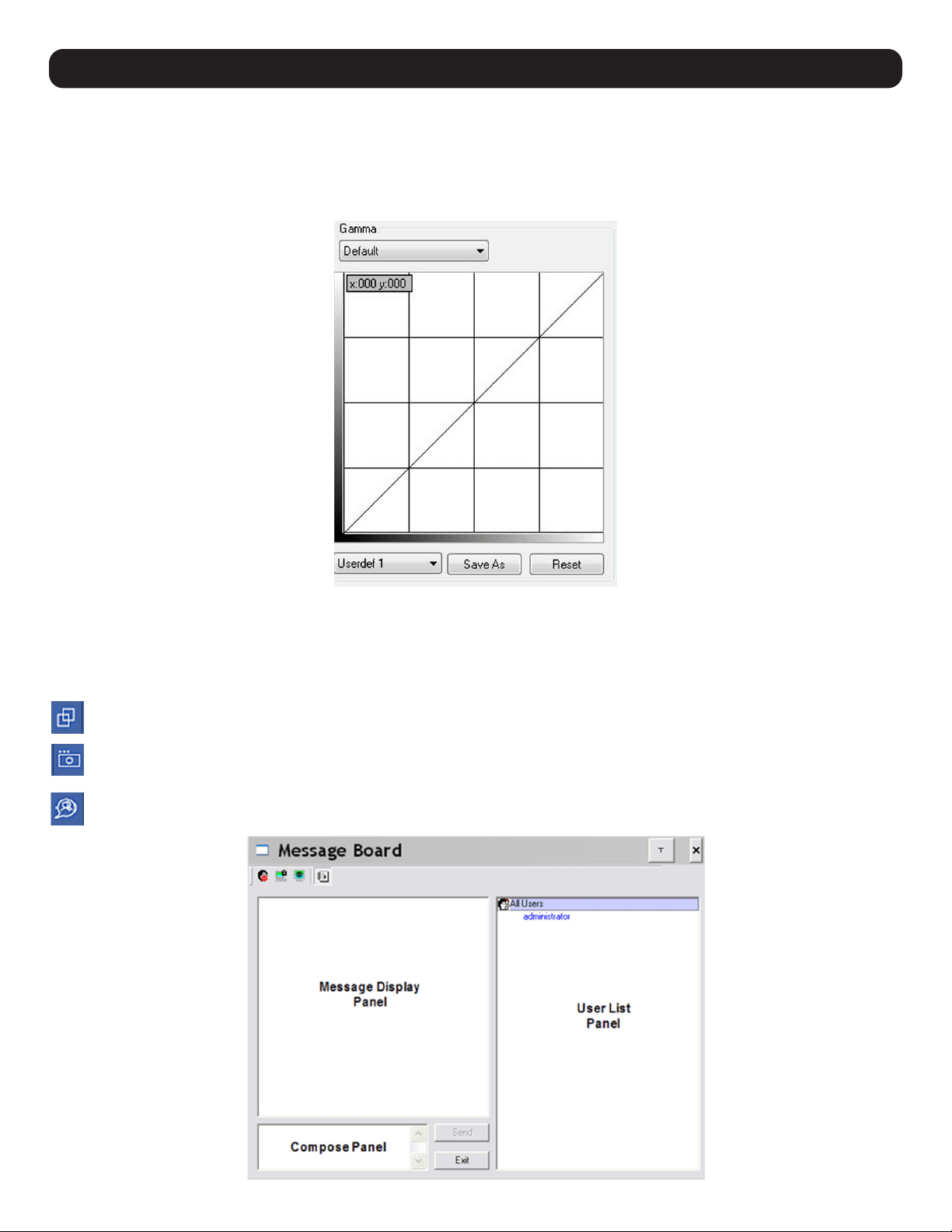
92
18. Remote Session Operation
Gamma Adjustment
If it is necessary to correct the gamma level for the remote computer, use the Gamma function in the Video Settings screen. Under the Basic
configuration, the gamma drop-down list includes ten preset and four user-defined gamma levels to choose from. Simply select the desired
setting from the drop-down list. To manually set gamma levels:
1. Click the Advanced button to open the gamma adjustment settings.
2. Click and drag the diagonal line at as many points as you wish to achieve the desired display output. Click the Reset button at any time
to abandon changes and return to the default gamma settings. Click the Cancel button to abandon changes and close the Video Settings
window.
3. To save the new gamma settings, select a user-defined setting from the drop-down list and click the Save button. Personalized gamma
settings will be saved to the selected user’s defined option.
Screen Mode – Toggles Full Screen mode on/off.
Snapshot – Takes a screenshot of the remote computer and saves it to the local computer. By default, snapshots are saved to the local
computer’s desktop. The file type, quality and location can be changed via the Customize Control Panel page.
Message Board – The B030-008-17-IP supports multiple user logins, which can cause access conflicts. To alleviate this problem, a
message board feature allows users to communicate with one another.
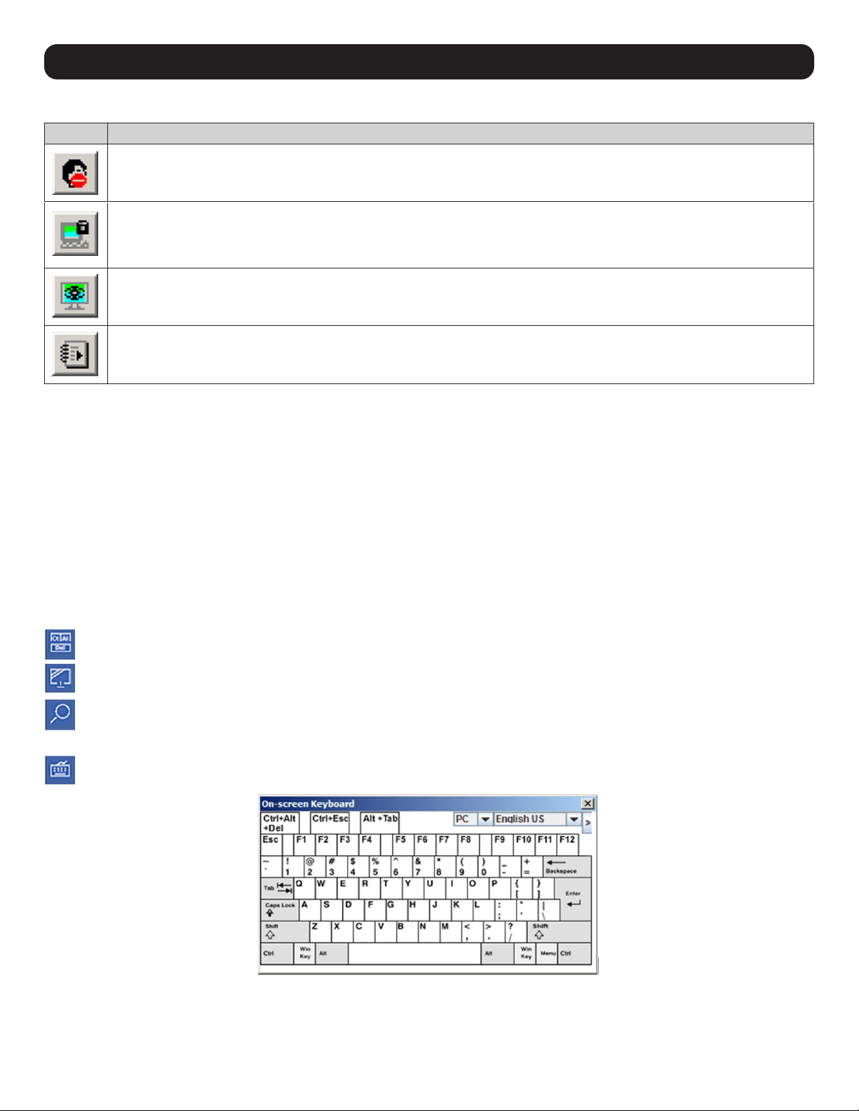
93
The buttons on the button bar at the top of the message board are toggles.
Button Function
Enable/Disable Chat – When disabled, this icon displays next to the disabled user’s name in the User List panel of all users’
message boards. Messages directed to the disabled user are not displayed on the message board. The button is shadowed when
chat is disabled.
Occupy/Release Keyboard/Video/Mouse – When using the KVM, other users cannot view video and cannot input keyboard or
mouse data. A prompt will appear on the locked out users’ monitors stating which user has occupied the KVM. The button in
the message board is shadowed and this icon displays next to the occupying user’s name in the User List of all users’ message
boards.
Occupy/Release Keyboard/Mouse – When you occupy the KVM, other users can see the video, but cannot input keyboard or
mouse data. The button is shadowed and this icon displays next to the occupying user’s name in the User List of all users’
message boards.
Show/Hide User List – When the User List is hidden, the User List panel closes. The button is shadowed when the User List is
open.
User List Panel
• The names of all users logged in appear in the User List panel. Select the names of the user(s) that you wish to communicate with before
sending your message.
• If a user has disabled chat, its icon displays before that user’s name.
• If a user has occupied the KVM or the KM, the corresponding icon displays before that user’s name.
Compose Panel
Type your message into this panel and then click the Send button or press [Enter] to post the message to the message board.
Note: You must select the user to communicate with from the user list. To send a message to all users, simply click All Users in the user list.
Message Display Panel
Messages that users post to the board, as well as system messages, display in this panel. If chat is disabled, messages that get posted do not
appear.
Ctrl – Alt – Delete – Sends the [Ctrl, Alt, Delete] command to the remote computer.
Set to Grayscale – Displays the remote video in grayscale. On slower networks, displaying the remote video in grayscale can help
improve keyboard and mouse response time.
Zoom – Zooms in on the remote display at 100%, 75%, 50% or 25%. Checking the 1:1 box will keep the screen contents sized in a
1:1 ratio, regardless of remote session display percentage.
Note: This feature is only available in windowed mode (Full Screen Mode is off).
On-Screen Keyboard – The B030-008-17-IP features an on-screen keyboard, available in multiple languages, with all of the standard
keyboard keys for each language. Click this icon to display the on-screen keyboard.
• To switch to a different language keyboard, open the drop-down list on the upper-right dropdown of the on-screen keyboard and select the
desired language.
• To expand the keyboard to include the number pad, click on the arrow icon to the right of the language drop-down menu.
18. Remote Session Operation
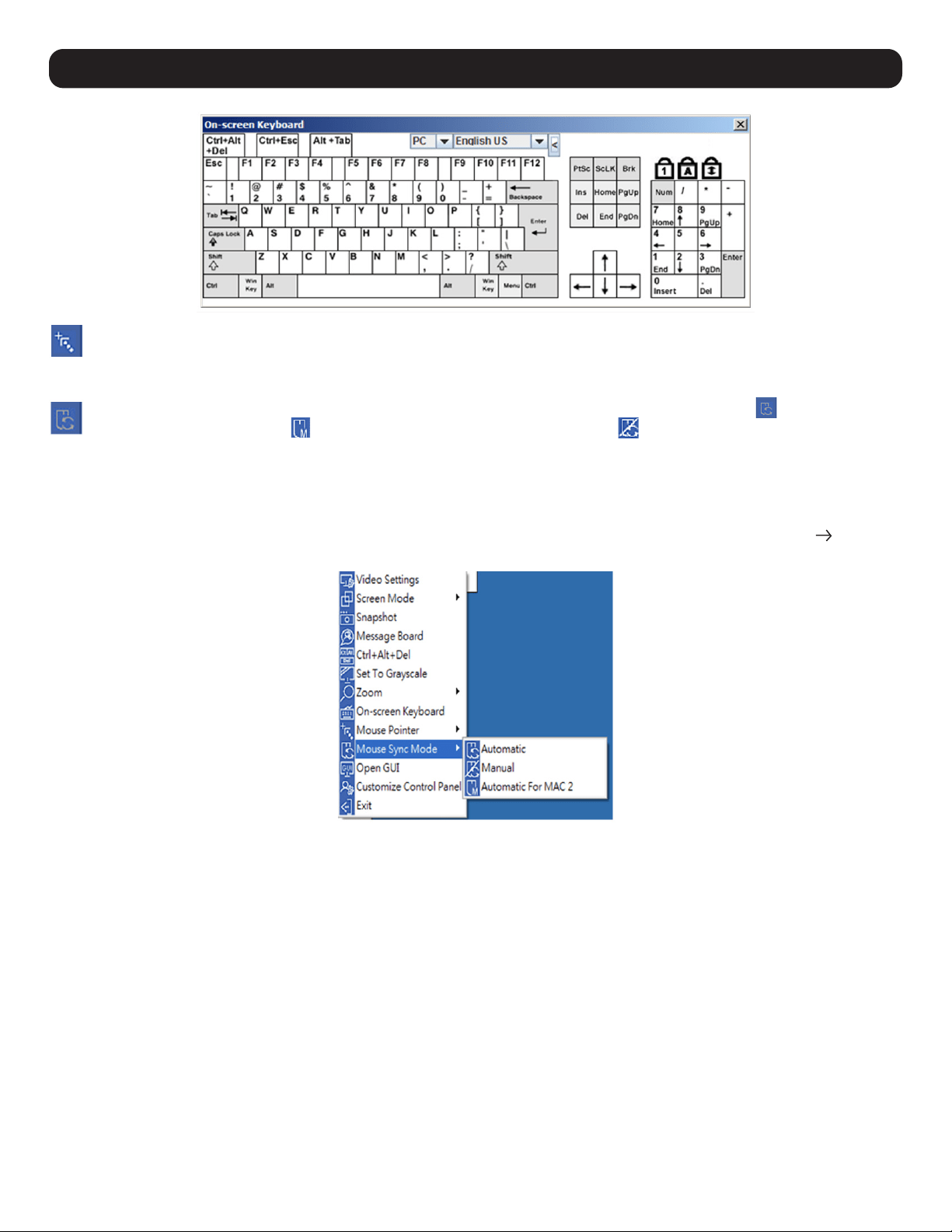
94
18. Remote Session Operation
Mouse Pointer – Click to choose how the local and remote mouse pointers are displayed. You can choose to display Dual mouse
pointers, Crosshairs mouse pointers, the local mouse pointer as a tiny dot, or only the remote mouse pointer. Dual mouse pointers
display both local and remote mice as arrows. Crosshairs pointers display the local mouse as a cross and the remote mouse pointer as
an arrow. When displaying the local mouse pointer as a tiny dot, the remote mouse pointer will be displayed as an arrow.
Mouse Sync Mode – Toggles between automatic and manual mouse sync modes. When set to automatic, the icon appears in the
toolbar. When set to manual, the icon appears. When set to Automatic for Mac, the icon appears.
Note: This feature is only available for Windows and Mac systems (G4 and higher) whose adapter attribute OS setting is configured for Win or Mac. All other
configurations must use manual mouse synchronization.
Mac Considerations
For Mac OS versions 10.4.11 and higher, a second DynaSync setting to choose from is available. If the default Mouse DynaSync result is not
satisfactory, try the Mac 2 setting. To select Mac 2, right click in the text area of the Control Panel and select Mouse Sync Mode Automatic
for Mac 2:
Manual Mouse Synchronization
If the local mouse pointer goes out of sync with the remote system’s mouse pointer, there are a number of methods to bring it back into sync.
Before trying any mouse synchronization procedures, it is always recommend to first go to the Mouse Properties Settings and set them
accordingly. The Mouse Properties Settings should be set on the computers attached to the KVM Switch, not the computer you are using to
access.
Note: In order for the local and remote mice to synchronize, a generic mouse driver supplied with the MS operating system must be used. If a third party driver
is installed - such as one supplied by the mouse manufacturer – it must be removed.
Windows 2000:
1. Open the Mouse Properties dialog box
2. Click the Motion tab
3. Set the mouse speed to the middle position (6 devices in from the left)
4. Set the mouse acceleration to None

95
18. Remote Session Operation
Windows XP and later:
1. Open the Mouse Properties dialog box
2. Click the Pointer Options tab
3. Set the mouse speed to the middle position (6 devices in from the left)
4. Disable Enhance Pointer Precision
Sun / Linux:
Open a terminal session and issue the following command:
Sun: xset m 1
Linux: xset m 0
Mouse Synchronization Procedures
If you are experiencing syncing problems after adjusting the mouse properties, try the following methods to help synchronize the local and
remote mouse pointers.
Note: Mouse synchronization may require several seconds to take effect. Wait for 15 to 30 seconds to ensure the mouse has had sufficient time to sync.
• When in a remote session, move the mouse pointer to the upper-center of the screen to open the control panel, and then move it back into
the remote screen. The mouse pointers should align.
• Drag the control panel to a different position on the screen.
• When in a remote session, move the pointer into all 4 corners of the screen (in any order).
• Perform a Video Auto Sync by right-clicking on the Video Settings icon in the control panel. In most cases, the local and remote mouse
pointers will sync following the video auto sync.
• Invoke the Adjust Mouse hotkey command (see the Hotkeys section in 13.1 Control Panel for more information). This hotkey command
defaults to F8, F7, F6.
• Adjust the video settings to decrease the amount of information being transferred over the network. The less data that is being sent, the
faster the response time. In particular, the Quality and Detect Tolerance settings in the Video Settings screen (see Video Settings section in
13.1 Control Panel for more information) can help improve keyboard and mouse response time.
• Go to the Network page in the Web Interface and reduce the Network Transfer Rate setting.
• Go to the display settings section of the remote computer and lower the video resolution, refresh rate and color settings.
• If the remote computer has a graphic desktop background, change it to a solid color background.
First Port – Skips to the first accessible port on the installation.
Previous Port – Skips to the first accessible port prior to the currently selected port.
Next Port – Skips to the first accessible port after the currently selected port.
Last Port – Skips to the last port on the installation.
Scan Ports – Initiates Auto Scan mode.
Array Mode – Initiates Panel Array mode. Refer to 18.3 Panel Array Mode for more information.
Open GUI – Opens the Web Interface.
Customize Control Panel – Opens the Customize Control Panel screen and allows users to choose which icons are displayed in the
control panel. Feature editing is also available.
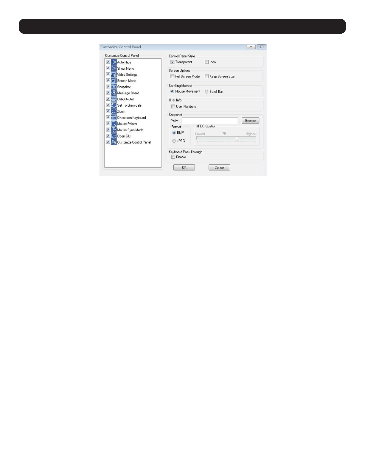
96
18. Remote Session Operation
Control Panel Style
This section lets a user determine how the control panel is displayed when it is dragged out of the default position in the top-center of the
screen.
Note: A second default position for the control panel is available at the bottom-center of the screen.
• When the Transparent box is checked, dragging the control panel away from one of the default locations will leave it displayed transparently
in whatever location it was dragged to.
• When the Icon box is checked, dragging the control panel away from one of the default locations will leave it displayed as an icon in
whatever location it was dragged to.
• When both the Transparent and Icon boxes are checked, dragging the control panel away from one of the default locations will leave it
displayed as a transparent icon in whatever location it was dragged to.
• When neither box is checked, dragging the control panel away from one of the default locations will leave it displayed as normal in whatever
location it was dragged to.
• If the control panel is located in the top-center or bottom-center default locations, checking these boxes will have no effect.
Screen Options
This section enables Full Screen Mode and Keep Screen Size as the default settings when a remote session is activated.
• Check the Full Screen Mode box to display the remote screen in Full Screen Mode for the next time logging in to a remote session.
• Check the Keep Screen Size box to enable the Keep Screen Size feature for the next time logging in to a remote session.
Scrolling Method
In instances when the remote screen display is larger than the monitor, you can choose how to scroll to the off-screen areas.
• By selecting Mouse Movement, the screen will scroll when moving the mouse pointer to the screen border.
• By selecting Scroll Bars, scroll bars appear around the screen borders that available to scroll to the off-screen areas.
User Info
If User Info is enabled, the total number of users remotely accessing the KVM will display on the Control Panel’s bottom row.
Snapshot
The Snapshot section determines where snapshots are sent to, what file type they are saved as; and if saved as a JPEG, the quality of the
JPEG image.
• Path – To select a location for snapshots to be saved, click on the Browse button next to the Path field and navigate to the desired location.
• Format – Check the file type button to select the snapshot format.
• JPEG Quality – If saving snapshots as JPEGs, the JPEG image quality can be selected here. The higher the quality of the image, the larger the
file size.
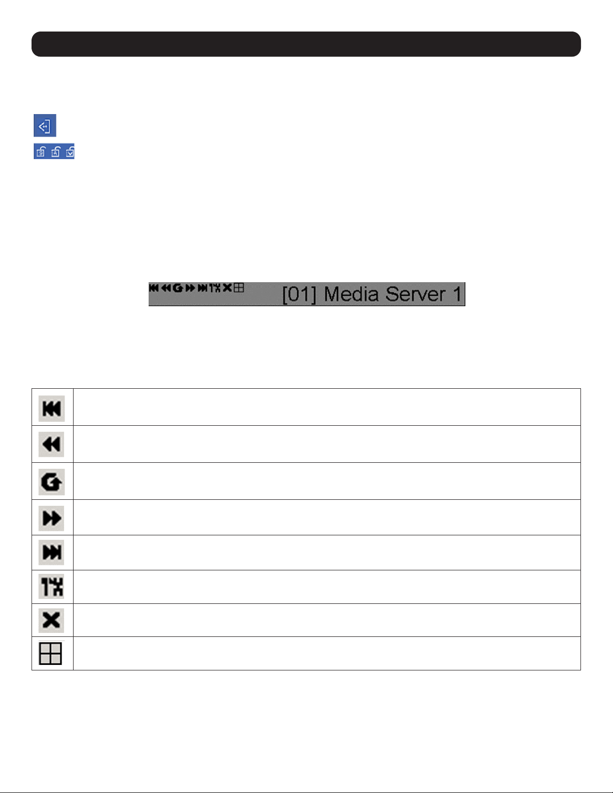
97
Keyboard Pass Through
When selected, the [Alt, Tab] function will be sent to the remote computer. When it is not selected, the [Alt, Tab] function is sent to the local
computer. It is deactivated by default.
Exit – Exits the remote session.
Lock LEDs – Display the status of the keyboard Num Lock, Caps Lock and Scroll Lock LEDs. Click the LEDs to toggle the
corresponding lock function on/off. When first initiating a remote session, the lock function may first need to toggle off/on to
ensure they are synced up with your keyboard.
18.2 Remote Session Toolbar
When remotely accessing a port, a secondary toolbar is provided to help control the port switching operations from within that port. There are
three hotkey combinations used to access the Remote Session Toolbar and/or Web Interface. When in a remote session:
• Press [Scroll Lock] twice to open the Remote Session Toolbar.
• Press [Scroll Lock] three times to open the Web Interface.
• When the Remote Session Toolbar is opened (see below), press [Scroll Lock] once to open the Web Interface.
Depending on the settings selected for the ID Display in the User Preferences section of the Web Interface, the Port Number and/or Port Name
will display on the right of the toolbar.
Note: When the toolbar displays, mouse input is confined to the toolbar area and keyboard input (other than the Scroll Lock hotkey) has no effect.
18.2.1 Remote Session Toolbar Icons
Skips to the first accessible port on the installation without needing to invoke the Web Interface.
Skip to the first accessible port previous to the current one without invoking the Web Interface.
Begins Auto Scan Mode. The KVM Switch automatically switches among the ports selected for Auto Scanning in the Port Select
and Filter functions. This allows the user to monitor their activity without having to switch among them manually.
Skips the current port to the next accessible port without invoking the Web Interface.
Skips the current port to the last accessible port on the installation without invoking the Web Interface.
Opens the Web Interface.
Closes the Remote Session Toolbar.
Invokes Panel Array Mode (refer to the 18.3 Panel Array Mode for more information.)
18. Remote Session Operation
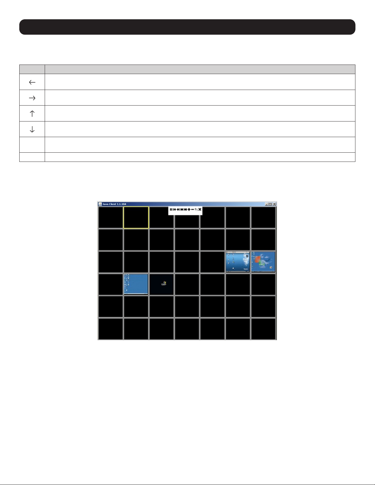
98
18. Remote Session Operation
18.2.2 Remote Session Toolbar Hotkeys
When the Toolbar is displayed, hotkeys can be used to switch between ports.
Hotkey Action
Skips to the first accessible port before the current port. To control the selected port, press [Esc] or click on the X icon in the
Toolbar
Skips to the first accessible port after the current port. To control the selected port, press [Esc] or click on the X icon in the
Toolbar
Skips the current port to the first accessible port on the installation. To control the selected port, press [Esc] or click on the X icon
in the Toolbar
Skips the current port to the last accessible port on the installation. To control the selected port, press [Esc] or click the X icon in
the Toolbar
A
Initiates an Auto Scan. To exit Auto Scan and control the currently selected port, press [Esc] or [Spacebar], or click on the X icon
in the Toolbar.
P Pauses an Auto Scan. To resume scanning, press any key other than the [Esc] or [Spacebar]
18.3 Panel Array Mode
Clicking the Panel Array icon on the Remote Session Toolbar or Control Panel initiates Panel Array Mode. Under this mode, your screen is
divided into a grid of panels:
• Each panel represents one port, starting with Port 1 at the upper left, continuing in sequence from left to right and top to bottom.
• When first initiated, the Array scans each of the ports selected for Auto Scanning in the Port Select and Filter functions, and displays
information about the port (port name, resolution, online status, port access status) at the bottom of the panel.
Note: The Panel Array scans at one-second intervals. The scan interval is not user definable.
The number of panels in the array can be increased or decreased by clicking the Show More Ports or Show Fewer Ports icons on the panel
array toolbar.
• If the computer connected to a port is online, its screen will display in the panel. If not, the panel will remain blank.
• Only ports accessible to the currently logged-in user are displayed. For ports that are not accessible, the panel will remain blank.
• If the mouse pointer is positioned over a panel, information about the port will display at the bottom of the panel.
• A computer/server connected to a port can be accessed by positioning the mouse pointer over its panel and double-clicking. This will switch
the user to the computer exactly as if he/she had selected it from the OSD Main screen.
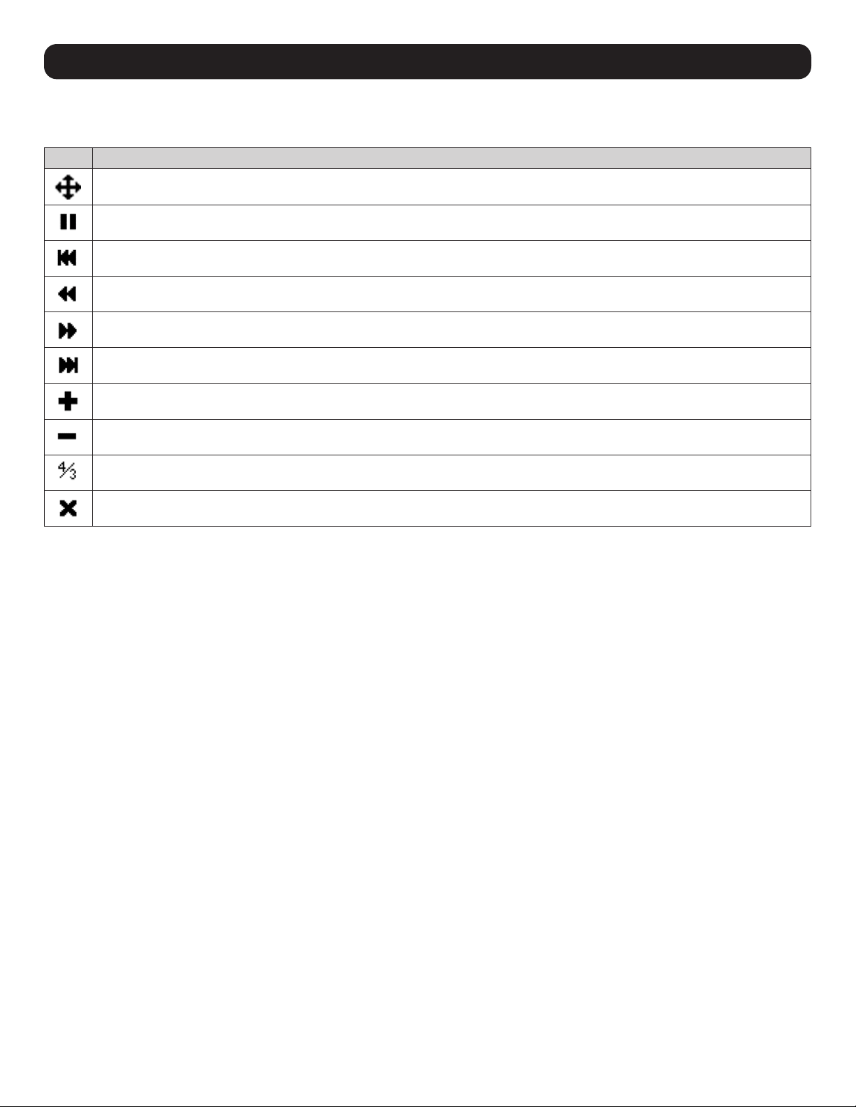
99
18. Remote Session Operation
18.3.1 Panel Array Toolbar Icons
The Panel Array Toolbar provides shortcut navigation and control of the panel array.
Icon Description
Click and drag any part of the toolbar that is not an icon to move the toolbar to another position on the screen.
Pauses panel scanning so the focus remains on the currently selected panel.
Moves the focus of the Panel Array scan backward four panels.
Moves the focus of the Panel Array scan to the previous panel.
Moves the focus of the Panel Array scan to the next panel.
Moves the focus of the Panel Array scan forward four panels.
Increases the number of panels in the array.
Decreases the number of panels in the array.
Toggles to a 4:3 aspect ratio.
Exits Panel Array mode.

100
19. Auto Scan Mode
The Auto Scan function automatically switches among all accessible ports at regular intervals so the user can monitor their activity without
having to manually switch between ports. The ports accessed in Auto Scan mode can be further filtered via the Filter section of the Port Access
page.
19.1 Setting the Scan Interval
The scan interval used during Auto Scan mode can be set in the User Settings menu (refer to User Preferences in 11.2 Port Access for more
information). The scan interval can be set from 1 to 255 seconds. The default is 5 seconds.
19.2 Initiating Auto Scan
Auto Scan Mode can be initiated in the Web Interface or a remote session. When in the Web Interface, initiate Auto Scan by clicking on the
Auto Scan button in the lower-left corner of the Port Access section. When in a remote session, initiate Auto Scan by opening the Remote
Session toolbar and tapping the A key. Once started, Auto Scan cycles through the ports in order, starting with the first accessible port on the
installation. During Auto Scan Mode, an S appears in front of the Port ID Display to indicate the port is being accessed under Auto Scan Mode.
19.3 Pausing Auto Scan
Auto Scan Mode can be paused in order to maintain focus on a particular computer by pressing the P key during an Auto Scan. When paused,
the S that displays in front of the Port ID will blink. Pausing to maintain focus on a particular computer may be more convenient than exiting
Auto Scan Mode. This is due to the user having to start from where they left off when they resume scanning. If exiting and then restarting Auto
Scan Mode, the scanning would start over from the first computer on the installation. To resume Auto Scan Mode after pausing, press any key
except [Esc] or [Spacebar], both of which will exit Auto Scan Mode completely.
19.4 Exiting Auto Scan
While Auto Scan Mode is in effect, ordinary keyboard functions are suspended. The user must exit Auto Scan Mode in order to regain normal
control of the keyboard. To exit Auto Scan Mode, press [Esc] or [Spacebar].
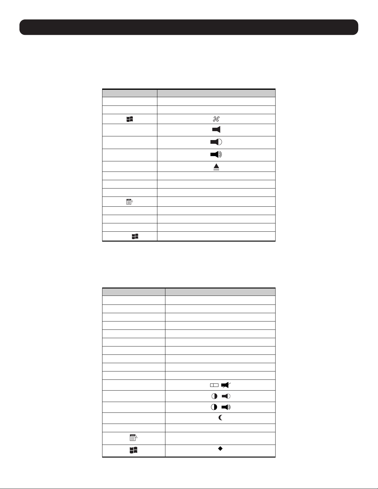
101
20. Appendix
20.1 Keyboard Emulation
20.1.1 Mac Keyboard
The PC compatible (101/104 key) keyboard can emulate the functions of the Mac keyboard. The emulation mappings are listed in the table
below.
PC Keyboard Mac Keyboard
[Shift] Shift
[Ctrl]
Ctrl
[Ctrl] [1]
[Ctrl] [2]
[Ctrl] [3]
[Ctrl] [4]
[Alt]
Alt
[Print Screen]
F13
[Scroll Lock]
F14
=
[Enter]
Return
[Backspace]
Delete
[Insert]
Help
[Ctrl]
F15
Note: When using key combinations, press and release (Ctrl), then press and release the activation key.
20.1.2 Sun Keyboard
The PC compatible (101/104 key) keyboard can emulate the functions of the Sun keyboard when Control [Ctrl] is used in conjunction with
another key. The corresponding functions are shown in the table below.
PC Keyboard Sun Keyboard
potS]T[ ]lrtC[
niagA]2F[ ]lrtC[
sporP]3F[ ]lrtC[
odnU]4F[ ]lrtC[
tnorF]5F[ ]lrtC[
ypoC]6F[ ]lrtC[
nepO]7F[ ]lrtC[
etsaP]8F[ ]lrtC[
dniF]9F[ ]lrtC[
tuC]01F[ ]lrtC[
[Ctrl] [1]
[Ctrl] [2]
[Ctrl] [3]
[Ctrl] [4]
pleH]H[ ]lrtC[
Compose
-
+
Note: When using key combinations, press and release (Ctrl), then press and release the activation key.

102
20. Appendix
20.2 Troubleshooting
20.2.1 General Operation
Problem Action
Erratic Operation. If a KVM switch is cascaded from it, the upper-level KVM must always be powered on before the
lower-level KVM. If the cascaded switch was turned on first, resetting it may resolve the issue. If
not, power off the installation and power everything on according to the installation instructions in
this manual.
• Reset the unit by pressing and holding the Reset button on the front of the unit for longer than
three seconds.
I can’t access the KVM, even though
I specified the IP address and port
number correctly.
If the KVM is behind a router, the router’s Port Forwarding (also referred to as Virtual Server) feature
must be configured.
Mouse and/or Keyboard not
responding.
• If accessing the KVM via local console, unplug and re-plug the cable(s) from the console port(s).
• Turn the connected computer/server off and then back on. All connected devices need to be
powered off when connecting to the KVM.
Sudden loss of network connection. Close your KVM connection. Wait approximately 30 seconds, then log in again.
No video display on the remote
console.
• Make sure the monitor resolution displaying the remote computer/server is higher than the
remote computer/server.
• Make sure the OSD toolbar is closed. Mouse movement is often required to bring the screen out
of sleep mode. If the OSD toolbar is open, your mouse input is not being received by the remote
computer/server.
When logging in from a browser, the
following message appears:
404 Object Not Found.
If a login string has been set (refer to 13.3 Login String for more information), make sure to
include the forward slash and correct login string when specifying the KVM’s IP address.
When I log in, the browser generates a
CA Root certificate is not trusted, or a
Certificate Error response.
The certificate can be trusted; you can proceed.
There are two mouse pointers after the
remote system is accessed.
The KVM automatically defaults to show both the local and remote mouse pointers. You can choose
to display both mouse pointers at the same time or only the remote mouse pointer.
The remote console display is distorted
and performing Autosync does not
resolve the problem.
• Switch to a port with a different resolution, then switch back.
• Lower the resolution and refresh rate for the computer/server connected to the port.
I have been given an account, but I
am unable to login
• Make sure you have correctly entered your username and password.
• Make sure your System Administrator has given you proper access to the KVM switch.
The Lock LEDs on the Control Panel do
not accurately reflect my Lock status
Click the Control Panel LEDs until they match those on your keyboard. Once matched up, changing
a Lock LED on the keyboard will also change it in the Control Panel and vice versa.
When I open a viewer, the web page
does not display properly and I receive
an error message that says “Problems
with this Web page might prevent it
from being displayed properly….”
• By default, IE6 and some versions of IE5 use the High security level for the Restricted Sites zone.
Windows Server 2003 uses High security for both the Restricted Sites and Internet zones. You
may need to enable Active Scripting, ActiveX Controls and Java Applets. To do this, follow these
steps: 1) In Internet Explorer, open the Tools menu and select Internet Options. 2) In the Internet
Options dialog box, click Security. 3) Click Default level, then click OK when prompted.
• Verify that Active Scripting, ActiveX Controls and Java Applets are not blocked. If some client
computers work and others does not, verify the Internet Explorer or another program (e.g.
antivirus, firewall, etc.) on your client computer are not configured to block Scripts, ActiveX
Controls or Java Applets.
• Verify your anti-virus program is not set to scan the Temporary Internet Files or Downloaded
Program Files folders.
• Delete all temporary internet related files by following these steps: 1) Open the Tools menu in
Internet Explorer and select Internet Options, 2) Click on the General tab, 3) Under Temporary
Internet Files, click Settings, 4) Click Delete Files and click OK when prompted, 5) Click Delete
Cookies and click OK when prompted, 6) Under History, click on Clear History, Yes and click OK
when prompted.
• Make sure you have the latest version of Microsoft DirectX installed.
• Make sure that you have the latest version of Java installed.

103
20. Appendix
20.2.2 Administration
Problem Action
After upgrading the firmware and
logging back in, the KVM appears to
still be using the old firmware version.
Clear your browser’s cache. Delete all temporary internet files and cookies. Close the browser and
reopen it to log in with a new session.
20.2.3 Mouse
Problem Action
Mouse movement is extremely slow. There is too much data transmission in your connection.
• If the remote computer’s wallpaper contains a substantial amount of graphics, switch it to a plain
wallpaper.
There are two mouse pointers on my
screen, how do I change this?
You can choose between three different pointer types. Refer to the Mouse Pointer section in 18.1
Control Panel for more information.
My mouse pointers do not sync.
Refer to the Mouse Pointer section in 18.1 Control Panel for more information.
20.2.4 AP Windows Client
Problem Action
Windows Client will not connect to the
KVM.
DirectX 8.0 or higher must be installed on your computer.
Remote mouse pointer is out of sync.
• Perform a Video Auto Sync (refer to Video Settings section in 18.1 Control Panel for more
information). This will usually sync the local and remote mouse pointers.
• Use the Adjust Mouse Hotkey command (refer to the Hotkeys section in 18.1 Control Panel for
more information).
• If this does not work, refer to the Mouse Pointer section in 18.1 Control Panel for more
information.
Part of the remote window is off my
monitor.
• If Keep Screen Size is not enabled (refer to the Screen Mode section for more information), try
performing a Video Auto Sync to sync the local and remote monitors. If this does not work, you
may have to manually adjust the Screen Position in the Video Settings screen.
• If Keep Screen Size is enabled, areas that are off the screen can be accessed by positioning the
mouse pointer on the far side of the area you want to scroll to.
The remote screen is rotated 90
degrees.
Enable Keep Screen Size (refer to 18.2 Control Panel for more information).
I cannot run Net Meeting when the
Windows Client is running.
Enable Keep Screen Size (refer to 18.2 Control Panel for more information).
My KVM is not showing up in the
device list when I open the AP
Windows Client.
• The port number entered into the Program field of your KVM’s Network page (refer to 7.6.2 IP
Installer for more information) must match the port number entered into the AP Windows Client’s
Port field. Only KVMs matching the port number entered into this field will show up in the device
list.
• The Enable Device List option must be checked on the Operating Mode page for your KVM switch
to show up in the Device List (refer to 11.12.2 Device Management for more information).
After upgrading the firmware to my
KVM switch, the AP Windows Client no
longer works.
The old .ocx file version was not deleted. Open Explorer and search for WinClient.ocx. Delete all
occurrences.

104
20. Appendix
20.2.5 WinClient ActiveX Viewer
Problem Action
The WinClient ActiveX Viewer will not
connect to the KVM switch.
DirectX 8.0 or higher must be installed on your client computer.
After upgrading the firmware to my
KVM switch, the WinClient ActiveX
Viewer no longer works.
The old .ocx file version was not deleted. Open Explorer and search for WinClient.ocx. Delete all
occurrences.
Part of the remote window is off my
monitor.
• If Keep Screen Size is not enabled (refer to 18.1 Control Panel for more information), try
performing a Video Auto Sync. If this does not work, you may have to manually adjust the video
via the Video Settings page.
• If Keep Screen Size is enabled, areas that are off the screen can be accessed by positioning the
mouse pointer on the far side of the area you want to scroll to.
The remote screen is rotated 90
degrees.
Enable the Keep Screen Size function (refer to 18.1 Control Panel for more information).
I cannot run Net Meeting when the
WinClient is running.
Enable the Keep Screen Size function (refer to 18.1 Control Panel for more information).
After logging in, I cannot open the
WinClient ActiveX viewer.
• You do not have the authority to install the WinClient Control Add-on on your client computer.
Have your system administrator run the program for you.
• Under Vista, you must also add the KVM switches URL to the list of trusted sites. Go to Tools >
Internet Options > Security > Trusted Sites > Sites.
When using Vista, I open the WinClient
ActiveX Viewer and try to mount a
driver or removable disk, but I am
receiving a message that says “Driver
not ready.”
This is due to Vista’s User Account Control (UAC). If you are the computer’s administrator, open your
browser by right-clicking and selecting Run as Administrator. If you are not the administrator, you
will need to have the administrator disable UAC.
20.2.6 Panel Array Mode
Problem Action
The video resolution is low quality. This occasionally occurs when the screens are scaled down to fit into each panel. Decrease the
number of panels displayed.
When multiple remote users are
logged in, some only receive a partial
image.
The first user to invoke Panel Array Mode should set it to display at least four panels.
20.2.7 Java Applet and AP Java Client
Problem Action
The AP Java Client won’t connect to
the KVM.
• Java Runtime Environment 6, Update 3 or higher must be installed on your computer.
• If a login string has been set, make sure to include the forward slash and correct string (refer to
13.3 Login String for more information) when specifying the KVM’s IP address.
• Try closing and reopening the Java client.
Pressing the Windows Menu key has
no effect.
Java does not support the Windows Menu key.
Java Client performance deteriorates. Exit the program and start again.
National language characters do not
appear.
You must set the appropriate keyboard language in the Port Properties tab of the Port Access page
(refer 11.2.1 Connections for more information).
After upgrading my KVM’s firmware and
logging into the OSD, my switch still
shows the old firmware version number.
You need to delete your Java temporary internet files. Open Control Panel > Java, and click on the
Settings button in Temporary Internet Files. In the Disk Space section, click on Delete Files. When
prompted, click OK.
When I try to add a folder to be
mounted as a Virtual Media Drive, I
am unable to select the folder. The
only option I have is desktop.
In the folder selection entry field, enter the root directory of the folder you want to add. After that,
the folders contained under the root directory will be displayed.

105
20. Appendix
20.2.8 Log Server
Problem Action
The Log Server program does not run. The Log Server requires the Microsoft Jet OLEDB 4.0 driver in order to access the database. This
driver is automatically installed with Windows ME, 2000 and XP. For Windows 98 or NT, go to the
Microsoft download site:
http://www.microsoft.com/data/download.htm to retrieve the driver file: MDAC 2.7 RTM Refresh
(2.70.9001.0).
Since this driver is used in Windows Office Suite, an alternate method of obtaining it is to install
Windows Office Suite. Once the driver file or Suite has been installed, the Log Server will run.
20.2.9 Sun Systems
Problem Action
Video display problems with HD15
interface systems (e.g. Sun Blade
1000 servers).*
• The display resolution should be set to 1024 x 768 @ 60 Hz:
Under Text Mode, go to OK mode and issue the following command:
setenv output-device screen:r1024x768x60 reset-all
Under XWindow:
1. Open a console and issue the following command:
m64config -res 1024x768x60
2. Log out
3. Log in
Video display problems with 13W3
interface systems (e.g. Sun Ultra
servers).*
• The display resolution should be set to 1024 x 768 @ 60 Hz:
Under Text Mode, go to OK mode and issue the following command:
setenv output-device screen:r1024x768x60 reset-all
Under XWindow:
1. Open a console and issue the following command:
m64config -res 1024x768x60
2. Log out
3. Log in
The local and remote mouse pointers
do not sync.
See Manual Sync Mode section in 18.1 Control Panel for more information.
* These solutions work for most common Sun VGA cards. If using them fails to resolve the problem, consult the Sun VGA card’s manual.

106
20. Appendix
20.3 Specifications
Model B030-008-17-IP B030-DP08-17DIP B030-DP16-17DIP
Model Description 8-Port 1U Rack-Mount Console
HDMI KVM Switch with 17 in. LCD
and IP Remote Access
8-Port 1U Rack-Mount Console
DisplayPort KVM Switch with
17 in. LCD and IP Remote
Access, Dual Rail
16-Port 1U Rack-Mount Console
DisplayPort KVM Switch with
17 in. LCD and IP Remote
Access, Dual Rail
Port Selection Methods Pushbutton, OSD,
Web Interface / Toolbar
Pushbutton, OSD, Hotkey,
Web Interface / Toolbar
Pushbutton, OSD, Hotkey,
Web Interface / Toolbar
External Console Ports HDMI (Female),
2 x USB-A (Female)
Displayport (Female),
2 x USB-A (Female)
Displayport (Female),
2 x USB-A (Female)
Computer Ports 8 8 16
RJ45 LAN Ports 1 1 1
Housing Metal, Dual-Rail Metal, Dual-Rail Metal, Dual-Rail
Power LEDs 1 x Green 1 x Green 1 x Green
Online LEDs 8 x Orange 8 x Orange 16 x Orange
Selected LEDs 8 x Green 8 x Green 16 x Green
Power Input Connector IEC-320-C14 IEC-320-C14 IEC-320-C14
I/P Rating 100-240V, 50/60 Hz 1A 100-240V, 50/60 Hz 1A 100-240V, 50/60 Hz 1A
On/Off Power Switch Yes Yes Yes
Additional USB Ports 1 (USB 1.1) 1 (USB 1.1) 1 (USB 1.1)
Reset Button Yes Yes Yes
Port Selection Pushbuttons 8 8 16
Keyboard/Mouse Emulation USB (PC, Mac, Sun) USB (PC, Mac, Sun) USB (PC, Mac, Sun)
Max Video Resolution
(Local and 2nd Console)
Remote Console does not
support HDCP
1920 x 1080 @ 60 Hz, DDC2B,
HDCP 1.4
1920 x 1080 @ 60 Hz, DDC2B,
HDCP 1.4
1920 x 1080 @ 60 Hz, DDC2B,
HDCP 1.4
Operating Temperature Range 32°F to 104°F / 0°C to 40°C 32°F to 104°F / 0°C to 40°C 32°F to 104°F / 0°C to 40°C
Storage Temperature Range -4°F to 140°F / -20°C to 60°C -4°F to 140°F / -20°C to 60°C -4°F to 140°F / -20°C to 60°C
Humidity 0 to 80% RH, Non-condensing 0 to 80% RH, Non-condensing 0 to 80% RH, Non-condensing
Dimensions (H x W x D) 1.74 x 18.9 x 26.77 in. /
44 x 480 x 680 mm
1.74 x 18.90 x 26.77 in. /
44 x 480 x 680 mm
1.74 x 18.9 x 26.77 in. /
44 x 480 x 680 mm
Weight 26 lb. / 11.8 kg 30.62 lb. / 13.89 kg 30.69 lb. / 13.92 kg
20.4 OSD Factory Default Settings
Setting B030-008-17-IP B030-DP08-17DIP B030-DP16-17DIP
OSD Hotkey [Scroll Lock] [Scroll Lock] [Scroll Lock] [Scroll Lock] [Scroll Lock] [Scroll Lock]
Port ID Display Duration 3 Seconds 3 Seconds 3 Seconds
Port ID Display Mode Port Number + Port Name Port Number + Port Name Port Number + Port Name
Scan Duration 5 Seconds 5 Seconds 5 Seconds
Screen Blanker 0 (Disabled) 0 (Disabled) 0 (Disabled)
Logout Timeout 30 Minutes 30 Minutes 30 Minutes
Beeper Y (Enabled) Y (Enabled) Y (Enabled)

107
21. Warranty and Product Registration
3-Year Limited Warranty
TRIPP LITE warrants its products to be free from defects in materials and workmanship for a period of three (3) years from the date of initial purchase.
TRIPP LITE’s obligation under this warranty is limited to repairing or replacing (at its sole option) any such defective products. To obtain service under this
warranty, you must obtain a Returned Material Authorization (RMA) number from TRIPP LITE or an authorized TRIPP LITE service center. Products must be
returned to TRIPP LITE or an authorized TRIPP LITE service center with transportation charges prepaid and must be accompanied by a brief description of the
problem encountered and proof of date and place of purchase. This warranty does not apply to equipment which has been damaged by accident, negligence or
misapplication or has been altered or modified in any way.
EXCEPT AS PROVIDED HEREIN, TRIPP LITE MAKES NO WARRANTIES, EXPRESS OR IMPLIED, INCLUDING WARRANTIES OF MERCHANTABILITY AND FITNESS FOR
A PARTICULAR PURPOSE. Some states do not permit limitation or exclusion of implied warranties; therefore, the aforesaid limitation(s) or exclusion(s) may not
apply to the purchaser.
EXCEPT AS PROVIDED ABOVE, IN NO EVENT WILL TRIPP LITE BE LIABLE FOR DIRECT, INDIRECT, SPECIAL, INCIDENTAL OR CONSEQUENTIAL DAMAGES ARISING
OUT OF THE USE OF THIS PRODUCT, EVEN IF ADVISED OF THE POSSIBILITY OF SUCH DAMAGE. Specifically, TRIPP LITE is not liable for any costs, such as lost
profits or revenue, loss of equipment, loss of use of equipment, loss of software, loss of data, costs of substitutes, claims by third parties, or otherwise.
PRODUCT REGISTRATION
Visit tripplite.com/warranty today to register your new Tripp Lite product. You’ll be automatically entered into a drawing for a chance to win a FREE Tripp Lite
product!*
* No purchase necessary. Void where prohibited. Some restrictions apply. See website for details.
Regulatory Compliance Identification Numbers
For the purpose of regulatory compliance certifications and identification, your Tripp Lite product has been assigned a unique series number. The series number
can be found on the product nameplate label, along with all required approval markings and information. When requesting compliance information for this
product, always refer to the series number. The series number should not be confused with the marketing name or model number of the product.
WEEE Compliance Information for Tripp Lite Customers and Recyclers (European Union)
Under the Waste Electrical and Electronic Equipment (WEEE) Directive and implementing regulations, when customers buy new electrical and electronic
equipment from Tripp Lite they are entitled to:
• Send old equipment for recycling on a one-for-one, like-for-like basis (this varies depending on the country)
• Send the new equipment back for recycling when this ultimately becomes waste
Tripp Lite has a policy of continuous improvement. Specifications are subject to change without notice. Photos and illustrations may differ slightly from actual
products.

108
22-03-426 93358C_RevD
1111 W. 35th Street, Chicago, IL 60609 USA • tripplite.com/support