
© 2022 Sony Corporation
Digital Motion Picture Camera
Operating Instructions
MPC-3628/MPC-3626
Firmware Version 1.0
VENICE 2
5-037-217-11 (1)
GB

2
Table of Contents
1. Overview
Features ............................................................ 3
System Configuration........................................8
Location and Function of Parts
..........................9
2. Preparation
Preparing a Power Supply ...............................17
Setting the Clock
..............................................18
Interchanging the Imager Block
.......................19
Attaching the VF Attachment and Handle
......20
Mounting a Lens and Adjusting the Flange Focal
Length
.......................................................21
Attaching a Viewfinder
................................... 24
Handling AXS Memory Cards
.......................... 26
Handling SD Cards for Saving Configuration
Data
..........................................................34
3. Camera Operations
Sub Display ..................................................... 35
Operations on the Home Screen of the Sub
Display
..................................................... 38
User Functions Screen
..................................... 48
Menu Operations
............................................ 54
Full Menu Operations
......................................64
Shooting Menu
...............................................65
Project Menu
................................................... 72
TC/Media Menu
.............................................. 76
Monitoring Menu
.............................................77
Audio Menu
....................................................84
Paint Menu
......................................................85
Technical Menu
............................................... 87
Maintenance Menu
......................................... 92
Clip Operations on the Sub Display ................93
Playback
..........................................................95
Operations on the Home Screen of the Mini
Display
.....................................................96
Clip Operations on the Mini Display................99
4. Network
Network Setup and Operations .................... 100
5. Shooting
Basic Operation .............................................. 107
Useful Functions
........................................... 108
6. Saving and Loading User Configuration
Data
User Configuration Data ..................................111
All Files
........................................................... 112
Scene Files
..................................................... 113
User Gamma Files
.......................................... 114
7. Connecting External Devices
Connecting a Remote Control Unit ................. 115
Connecting External Monitors and Recording
Devices
....................................................120
External Synchronization
............................... 121
8. Appendix
Usage Precautions .........................................122
Recording Formats and Output Signals
.........125
AXS Clip Recording/Playback Time
................ 135
Error/Warning Indications..............................137
Items Saved in Files
.......................................139
Recording and Output Metadata List
............ 146
Licenses..........................................................149
Specifications ................................................ 150

3
1. Overview
Features
New 8.6K 36 mm × 24 mm full frame
CMOS image sensor (MPC-3628)
The MPC-3628 is equipped with a newly
developed 36mm × 24mm full frame, 8.6K
CMOS image sensor and can record images
up to 8640×5760 pixels.* By switching the
imager mode, the unit supports standard
Super 35mm 24.1mm × 12.7mm, 5792×3056
pixel resolution and 6:5 anamorphic, Super
35mm 24.1mm × 20.2mm, 5792×4854 pixel
resolution.* This makes the unit effective not
only for 8K content production but also for
VFX compositing. It is also possible to produce
high-quality 4K content by oversampling from
8.6K resolution content.
* Full-Frame and Anamorphic modes require licenses
sold separately.
6K 36mm × 24mm full frame CMOS
image sensor (MPC-3626)
The MPC-3626 features the same image
sensor as VENICE (MPC-3610) and supports
image capture at resolutions up to 6048×4032
pixels.* By switching the imager mode, the
unit supports standard Super 35mm 24.3mm
× 12.8mm, 4096×2160 pixel resolution
(equivalent to 3-perforation motion picture
film) and 4:3 anamorphic, Super 35mm
24.3mm × 18.3mm, 4096 × 3024 pixel
resolution (equivalent to 4-perforation motion
picture film).*
* Full-Frame and Anamorphic modes require licenses
sold separately.
Two interchangeable image sensors
The 8.6K image sensor and 6K image sensor
both feature system compatibility, allowing
the user to interchange the image sensor used
for operation. The VENICE (MPC-3610) imager
block is also compatible and can be attached
to the MPC-3628/3626.
Wide latitude
The MPC-3628 supports 16 stops of latitude,
while the MPC-3626 supports 15+ stops
of latitude. It features very low noise for
delivering phenomenal images in conditions
from searing sunlight to almost no light,
allowing for unprecedented creative freedom
in grading.
Wide color space capture
Images can be captured in a color space that
exceeds DCI-P3. The degree of freedom in the
grading is dramatically improved when using
Sony’s S-Gamut3 and S-Gamut3.Cine color
space together with S-Log3.
Dual Base ISO
Two types of base sensitivity are supported.
Using the low Base ISO setting (MPC-3628:
ISO 800, MPC-3626: ISO 500) under normal
lighting conditions or the high Base ISO
setting (MPC-3628: ISO 3200, MPC-3626: ISO
2500) under low light conditions allows you
to maintain the latitude balance between
highlights and lowlights when shooting,
without graining (noise).
PL lens mount
Equipped with the industry-standard PL lens
mount. The lens mount supports Cooke /i
technology, and lens information is recorded
as metadata frame by frame. Lens distortion
and shading metadata are recorded,
compatible with Cooke’s /i third generation
metadata technology (/i
3
) and ZEISS eXtended
Data Technology.
E-mount lens support
E-mount lenses are supported by removing
the PL lens adaptor. E-mount lenses are
smaller and lighter than PL lenses, and are
available in a diverse lineup for expanded
possibilities in image reproduction.
Imager block extension
On the MPC-3626 equipped with a 6K image
sensor, the imager block can be extended
from the camera body by 2.7 m (8.9 ft) or
5.5 m (18 ft) by connecting the CBK-3610XS
Camera Extension System, which also enables
shooting with a more compact camera head.
8-position optical ND filter
Employs an 8-position optical ND filter. It
offers a wide ND range of 0.3ND (1/2 = 1 stop)
to 2.4ND (1/256 = 8 stops) that reduces time
lost on set changing external ND filters. The
ND filter mechanism is servo-controllable, and
can be controlled from a computer, tablet, or
RM/RCP controller.
High Frame Rate (HFR) shooting
The 8.6K image sensor can record X-OCN at
frame rates up to 90 FPS, while the 6K image
sensor can record X-OCN at up to 120 FPS.
X-OCN and 4K ProRes recording formats
Video can be recorded in 16-bit X-OCN or 4K
ProRes, as standard recording formats, to AXS
memory cards. X-OCN is a format that can be
handled natively by many NLEs and grading
tools, and is recorded at the full resolution of
each sensor in each mode. 4K ProRes is widely
used as a 4K video format, and the image
captured by each image sensor in each mode
is oversampled* and recorded in 4K ProRes.
* When using the 6K image sensor (MPC-3626) in 4K
17:9, 4K 16:9, or 4K 2.39:1 imager mode, the captured
4K image is recorded as-is.
Compact body and intuitive operation
A relatively compact design for a device
equipped with a large full-frame image
sensor, achieved using Sony’s miniaturization
technology, which allows easier shooting in
confined spaces or on drones. The position,
shape, and size of the control buttons reflect
the requirements of camera operators
for intuitive operation. They also feature
backlighting for ease of use in dark locations.
Engineered to survive
The chassis is made from magnesium alloy for
high robustness and durability. The ventilation
system is completely isolated from all
electronic components to prevent ingress of
dust, sand, and liquids.* The silent-running fan
can be removed and cleaned on-set quickly
and easily to maintain high readiness.
* Design protects against dust and rain, but cannot
completely prevent the ingress of dust and liquid.
Modular design
The design allows you to flexibly support
various rigs and peripheral equipment
according to the shooting application. The top
handle and viewfinder are easily adjustable to
maintain ergonomic balance and ease of use
with lenses.
Intuitive and familiar on-set menu
operation
The menu screen is available from both sides
of the camera, with the main control display
on the Assistant side of the camera for fast
access to the camera settings by the camera
assistant while shooting. An OLED mini display
on the Operator side allows the operator to
access commonly accessed features such
as ND filter position, shutter, white balance,
exposure index (EI), and frame rate (FPS),
1. Overview: Features
4
making it convenient for the operator to check
the status of the unit.
Paint control from RM/RCP and this unit
The unit supports control from an RM/
RCP remote control panel that can be used
with broadcast camcorders and system
cameras. Adjustment of various paint items is
supported. Paint control operations are also
supported using the full menu of the unit.
Effective Picture Size
The unit supports shooting in the following effective picture sizes.
MPC-3628
[Note]
A software license is required to shoot in 8.6K 3:2, 8.2K 17:9, 7.6K 16:9, and 5.8K 6:5.
8.6K 3:2
5.8K 6:5
5.8K 17:9
5.4K 16:9
7.6K 16:9
8.2K 17:9
1. Overview: Features
5
MPC-3626
[Note]
A software license is required to shoot in 6K 3:2, 6K 1.85:1, 6K 17:9, 6K 2.39:1, 5.7K 16:9, 4K 6:5, 4K 4:3, and 4K 4:3
Surround View.
6K 3:2
6K 1.85:1
6K 17:9
4K 6:5
4K 4:3
6K 2.39:1
4K 2.39:1
4K 17:9
(DCI 4K)
3.8K 16:9
(Ultra HD)
5.7K 16:9
Software Licenses
You can select software licenses (optional) according to the intended usage of the unit.
Software licenses are installed using Maintenance > License Options (page 92) in the full
menu.
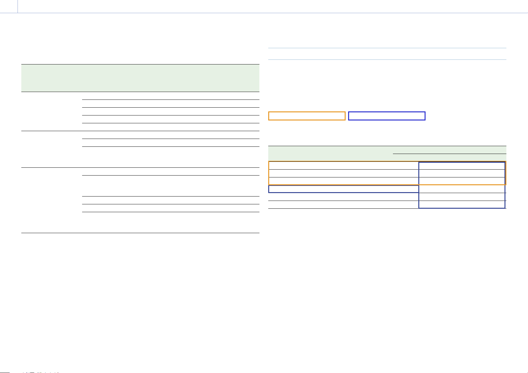
MPC-3628
Software license Imager
mode
Effective
number of
pixels
(Image pixels)
W × H (mm) Project frame rate
FULL-FRAME LICENSE
1)
8.6K 3:2 8640 × 5760 35.9 × 24.0 23, 24, 25, 29
8.2K 17:9 8192 × 4320 34.1 × 18.0 23, 24, 25, 29, 47, 50, 59
7.6K 16:9 7680 × 4320 32.0 × 18.0 23, 24, 25, 29, 50, 59
ANAMORPHIC LICENSE 5.8K 6:5 5792 × 4854 24.1 × 20.2 23, 24, 25, 29, 47
License not required
1)
5.8K 17:9 5792 × 3056 24.1 × 12.7 23, 24, 25, 29, 47, 50, 59
5.4K 16:9 5434 × 3056 22.6 × 12.7 23, 24, 25, 29, 50, 59
1) The Anamorphic License is required to enable ratio settings, other than Off(1.0×), for the de-squeeze function.
1. Overview: Features
6
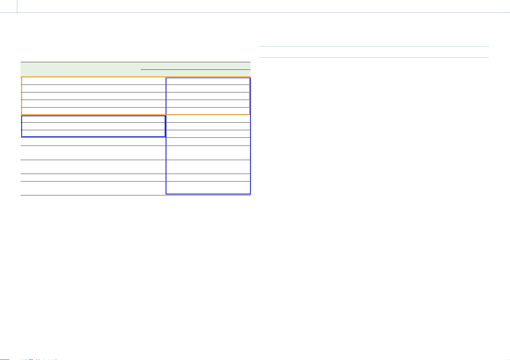
MPC-3626
Software license Imager
mode
Effective
number of
pixels
(Image pixels)
W × H (mm) Project frame rate
FULL-FRAME LICENSE
1)
6K 3:2 6048 × 4032 35.9 × 24.0 23, 24, 25, 29, 47, 50, 59
6K 1.85:1 6054 × 3272 36.0 × 19.4 23, 24, 25, 29, 47, 50, 59
6K 17:9 6054 × 3192 36.0 × 19.0 23, 24, 25, 29, 47, 50, 59
6K 2.39:1 6048 × 2534 35.9 × 15.0 23, 24, 25, 29, 47, 50, 59
5.7K 16:9 5674 × 3192 33.7 × 18.9 23, 24, 25, 29, 50, 59
ANAMORPHIC LICENSE 4K 6:5 4096 × 3432 24.3 × 20.4 23, 24, 25, 29, 47, 50, 59
4K 4:3 4096 × 3024 24.3 × 18.0 23, 24, 25, 29, 47, 50, 59
4K 4:3
Surround
View
4096 × 3024
(4552 × 3360)
24.3 × 18.0
(27.0 × 20.0)
23, 24, 25, 29
License not required
1)
4K 17:9 4096 × 2160 24.3 × 12.8 23, 24, 25, 29, 47, 50, 59
4K 17:9
Surround
View
4096 × 2160
(4552 × 2400)
24.3 × 12.8
(27.0 × 14.3)
23, 24, 25, 29
4K 2.39:1 4096 × 1716 24.3 × 10.3 23, 24, 25, 29, 47, 50, 59
3.8K 16:9 3840 × 2160 22.8 × 12.8 23, 24, 25, 29, 50, 59
3.8K 16:9
Surround
View
3840 × 2160
(4268 × 2400)
22.8 × 12.8
(25.4 × 14.3)
23, 24, 25, 29
1) The Anamorphic License is required to enable ratio settings, other than Off(1.0×), for the de-squeeze function.
Supported Shooting Frame Rates and De-Squeeze Values
The following table shows the supported shooting frame rates and De-Squeeze values
(page 72) in each imager mode.
[Note]
The following shows the supported shooting frame rates when the video format is X-OCN. For ProRes, the supported
maximum shooting frame rates are different (page 44).
FULL-FRAME LICENSE ANAMORPHIC LICENSE
MPC-3628
Imager mode Shooting frame rate De-Squeeze
Off(1.0×)
1.25× 1.3× 1.5× 1.65× 1.8×
2.0×
8.6K 3:2 1 to 30 Yes Yes Yes Yes Yes Yes Yes
8.2K 17:9 1 to 60 Yes Yes Yes – Yes Yes Yes
7.6K 16:9 1 to 60 Yes – – – – – –
5.8K 6:5 1 to 48 Yes – – – – – Yes
5.8K 17:9 1 to 60, 66, 72, 75, 88, 90 Yes Yes Yes – Yes Yes Yes
5.4K 16:9 1 to 60, 66, 72, 75, 88, 90 Yes – – – – – –
1. Overview: Features
7
MPC-3626
Imager mode Shooting frame rate De-Squeeze
Off(1.0×)
1.25× 1.3× 1.5× 1.65× 1.8×
2.0×
6K 3:2 1 to 60 Yes Yes Yes Yes Yes Yes Yes
6K 1.85:1 1 to 60, 66, 72 Yes – – – – – –
6K 17:9 1 to 60, 66, 72 Yes Yes Yes – Yes Yes Yes
6K 2.39:1 1 to 60, 66, 72, 75, 88, 90 Yes – – – – – –
5.7K 16:9 1 to 60, 66, 72 Yes – – – – – –
4K 6:5 1 to 60, 66, 72 Yes – – – – – Yes
4K 4:3 Surround 1 to 30 Yes – Yes – Yes Yes Yes
4K 4:3 1 to 60, 66, 72, 75 Yes – Yes – Yes Yes Yes
4K 17:9 Surround 1 to 48 Yes Yes Yes – Yes Yes Yes
4K 17:9 1 to 60, 66, 72, 75, 88, 90, 96,
100, 110
Yes Yes Yes – Yes Yes Yes
4K 2.39:1 1 to 60, 66, 72, 75, 88, 90, 96,
100, 110, 120
Yes – – – – – –
3.8K 16:9 Surround 1 to 48 Yes – – – – – –
3.8K 16:9 1 to 60, 66, 72, 75, 88, 90, 96,
100, 110
Yes – – – – – –
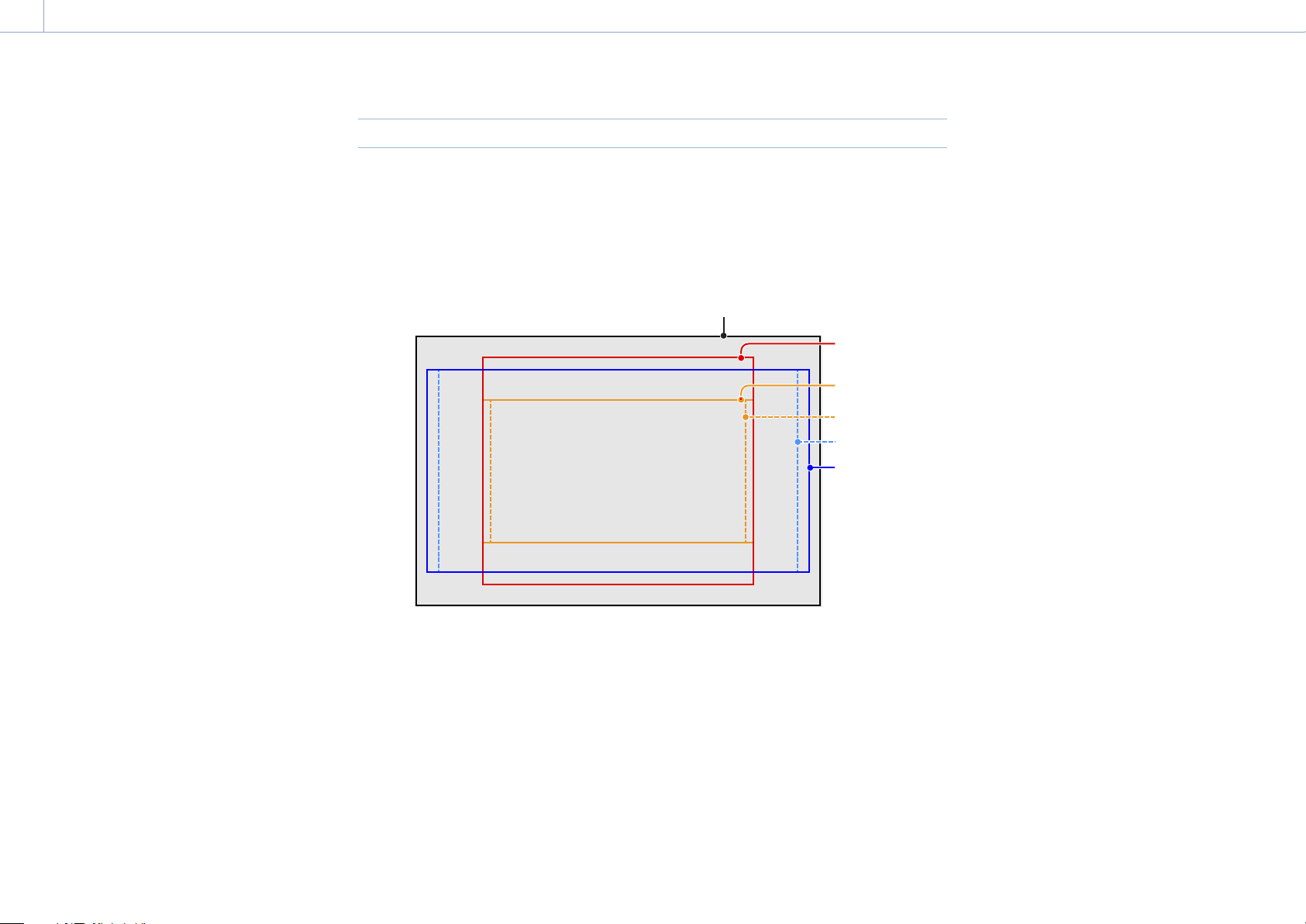
Surround View (MPC-3626)
Surround View is a mode available in the following imager modes that displays an image range
that includes a 5% outer region beyond the effective picture size (top/bottom/left/right) in the
viewfinder and SDI monitor output, allowing you to view a larger image range when shooting.
The recorded image area does not include the outer region.
4K 4:3
4K 17:9
3.8K 16:9
[Notes]
• In this mode, limitations on the maximum project frame rate setting may apply.
• In 4K 4:3 mode with de-squeeze ratio of 2.0×, the image area includes only 5% of the top and bottom outer
regions.
1. Overview
8
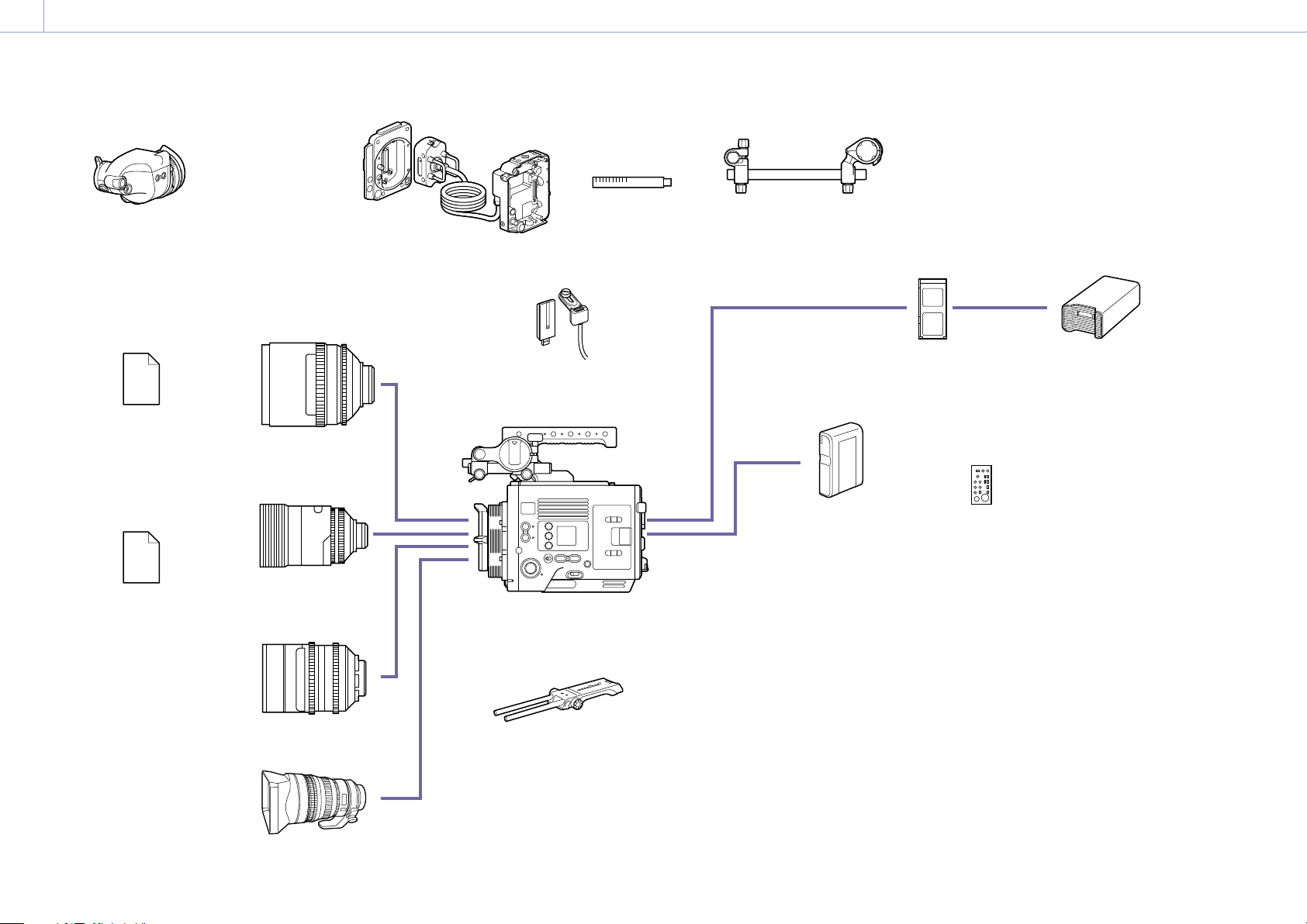
System Configuration
* Supported for 6K image sensor only
MPC-3628/
MPC-3626
VCT-FSA5
Shoulder Adaptor
DVF-EL200
Viewfinder
(VF cable A-2203-745-A (supplied
with unit) or 1-912-598-21 is required)
ECM-680S, ECM-678, ECM-674
Microphone
(EC-0.5X3F5M is required)
Microphone Holder base assembly (A-2182-620-B)
Rod clamp (A-2182-621-B)
Rod (4-684-612-01)
Microphone Holder assembly (X-2596-733-2)
Screws P2.6×8 (2) (7-627-556-98)
BP-GL95B
Battery Pack
SCL-PK6,
SCL-P11X15
S35 PL Lens
CBKZ-3620A,
CBKZ-3620AM,
CBKZ-3620AW
ANAMORPHIC
LICENSE
CBKZ-3620F,
CBKZ-3620FM,
CBKZ-3620FW
FULL-FRAME
LICENSE
Anamorphic Lens
(PL-mount / E-mount)
CBK-3610XS*
Camera Extension System
CBK-WA02
5 GHz/2.4 GHz Wireless LAN
Adaptor
Full-Frame Lens
(PL-mount / E-mount)
SELP28135G, SEL1224GM, SEL1635GM, SEL2470GM, SEL70200GM, SEL100400GM,
SEL24F14GM, SEL35F14GM, SEL50F12GM, SEL85F14GM, SEL100F28GM
E-mount lens
AXS-A512S24,
AXS-A512S48,
AXS-A1TS48,
AXS-A1TS66
AXS Memory Card
AXS-AR3
AXS Memory Card
Reader
RM-B170/B750
RCP-1000/1500/1530/3100/3500
RCP-1001/1501/3501
Remote Control Unit
1. Overview
9
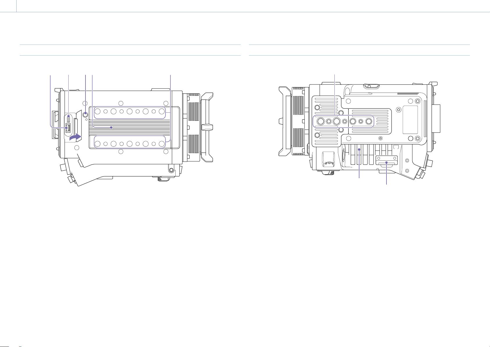
Location and Function of Parts
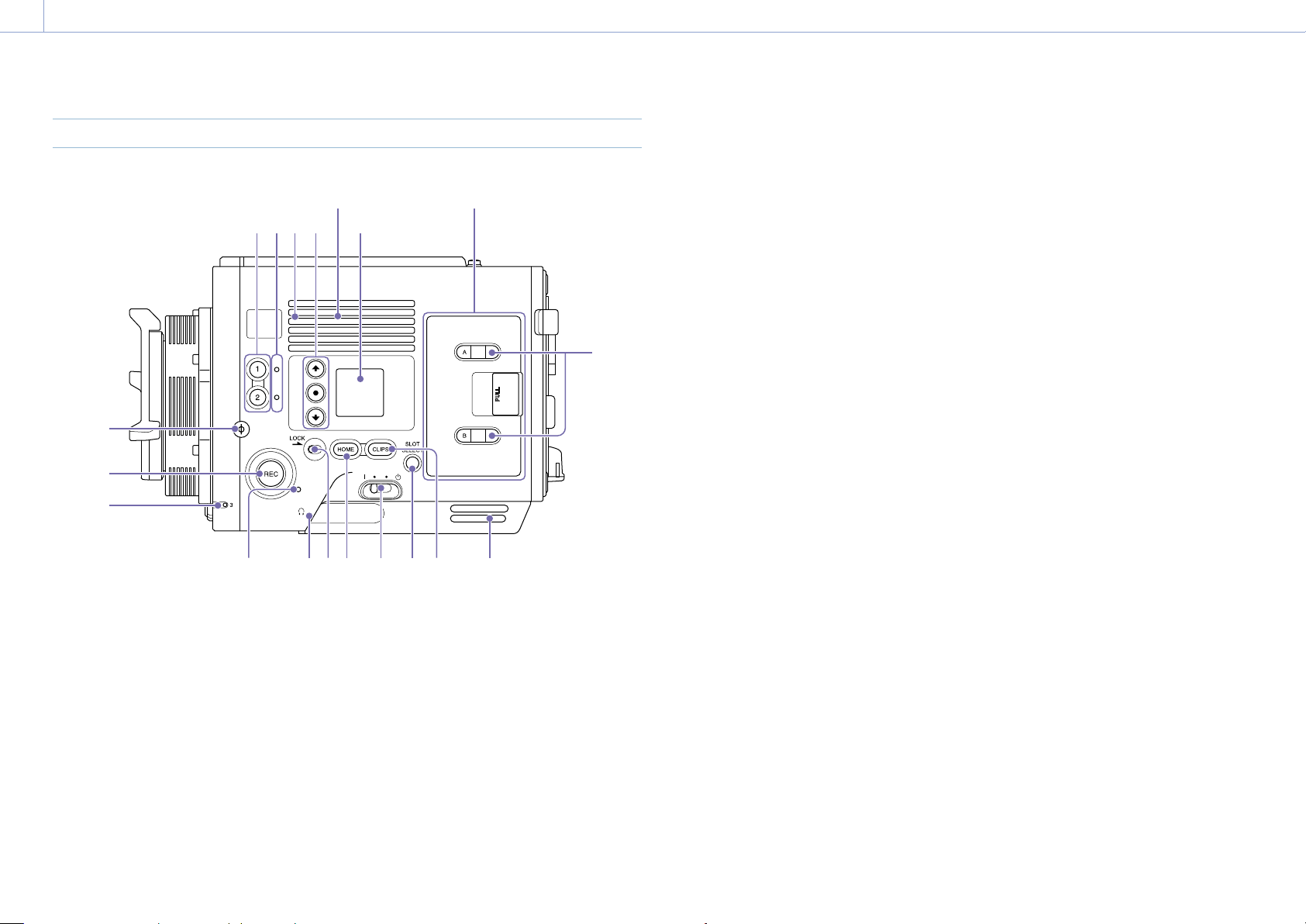
Operator Side
Air inlet
53
8 7910111213
15
16
14
1 2 4
6
Air inlet
AXS memory card slot
block (page 10)
[Note]
Do not operate with the air inlet blocked.
1. ASSIGN (assignable) buttons 1/2
(page 48)
Assign functions using the EDIT page of the
user functions screen (page 48).
The assigned function toggles between on/off
(enabled/disabled) or is activated with each
press.
2. ASSIGN (assignable) lamps 1/2
(page 48)
The lamp is lit orange when the assigned
function is on (enabled) or activated, and not
lit when the function is off (disabled).
3. Built-in speaker
You can monitor the input audio during
shooting/recording and playback sound
during playback. The speaker also sounds
alarms to reinforce visual warnings
(page 95).
If you connect earphones to the headphones
jack, the speaker output is suppressed
automatically.
[Note]
If configured such that the internal microphone captured
sound is audible from the built-in speaker, howling may
occur if the monitor volume is increased.
4. Mini display ITEM keys 1 to 3
Controls the operation of functions on the
mini display (page 96).
5. Mini display
Displays various setup items, such as
shutter angle, that you can check or modify
(page 96).
6. ACCESS lamps (SLOT A/B)
Each lamp is lit when the recording media in
AXS card slot A/B is the target for recording/
playback and when data is being written to or
read from the recording media in AXS card slot
A/B (page 26).
7. CLIPS button
Press to display the clip screen on the mini
display to enable clip operations (page 99).
Simultaneously, the clip list screen is displayed
on the sub display and can also be used for
clip operations.
To switch from playback mode to shooting
mode, press the HOME button.
8. SLOT SELECT (AXS memory card select)
button
Press to switch the active slot.
9. Power switch
Set to the (ON) position to turn the power on.
Set to the (OFF) position to turn the power
off.
[Notes]
• This unit uses a small amount of standby power
even when the power switch is set to OFF. Remove
the battery pack if the unit will not be used for a
prolonged period.
• When removing the battery pack or the DC IN
power, be sure to first set the power switch to the
OFF position. Interrupting the power supply during
recording or during memory card access could cause
a malfunction.
10. HOME button
Press to clear the item selection display and
return to the Home screen on the mini display.
If pressed when the unit is in playback
state, the unit transitions to shooting mode
(page 96).
11. LOCK switch
Locks the operation of the buttons on the
Operator side. When locked, the switch
background LED lights in orange.
12. Headphones connector (stereo mini jack)
Connect to earphones for audio monitoring.
You can monitor the input audio during
shooting/recording and playback sound
during playback (page 95).
[Notes]
• Use monaural (2-pole) or stereo (3-pole) type
earphones. The use of other devices may damage
the unit.
• Use 16-ohm impedance earphones.
13. REC ACTIVE lamp
The lamp is lit green when the REC button is
enabled.
14. ASSIGN (assignable) lamp 3 (page 48)
The lamp is lit orange when the assigned
function is on (enabled) or activated, and not
lit when the function is off (disabled).
15. REC (recording start/stop) button/lamp
Press to start recording, turning the REC lamp
on. Press again to stop recording, turning the
REC lamp off (page 107).
The REC lamp flashes when a device error or
warning occurs.
16. Ф (phi) mark
The Ф (phi) mark is on the same plane as the
image sensor.
To measure the precise distance between the
unit and the subject, use the
Ф
(phi) mark as a
reference.
1. Overview: Location and Function of Parts
10
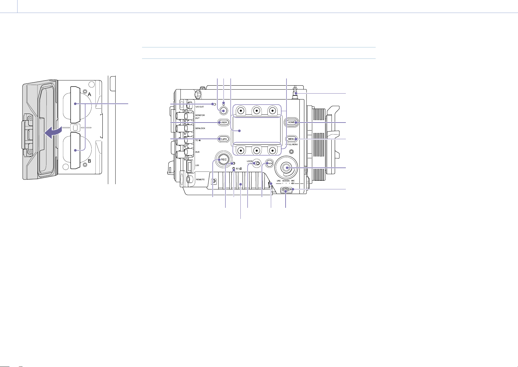
AXS memory card slot block (page 26)
The AXS memory card slots are located behind
the cover.
1
1. AXS memory card slots A/B
Assistant Side
1 2 3 4
6
5
7
8
9
1011
12
13
14
15
16
17
18
19
1 2 3
4 5 6
Air vent
1. ASSIGN (assignable) button 4 (page 48)
Assign functions using the EDIT page of the
user functions screen (page 48).
The assigned function toggles between on/off
(enabled/disabled) or is activated with each
press.
2. ASSIGN (assignable) lamp 4 (page 48)
The lamp is lit orange when the assigned
function is on (enabled) or activated, and not
lit when the function is off (disabled).
3. Sub display
Allows you to check the operation status
of the unit and make various settings
(page 36).
With the Home screen displayed, press and
hold the BACK button (page 11) and turn
the MENU dial to adjust the brightness of the
sub display and mini display.
The brightness can also be adjusted using
Technical > Panel Control > Brightness level
(page 89) in the full menu.
4. Sub display ITEM keys 1 to 6
Controls the operation of functions on the sub
display (page 54).
5. Tape measure hook
The tape measure hook is on the same plane
as the image sensor. To measure the precise
distance between the unit and the subject,
use the tape measure hook as a reference.
You can attach the end of a tape measure to
the hook, and measure the distance from the
subject.
6. HOME button
Press to clear the display and return to the
Home screen on the sub display
(page 38)
.
If pressed when the unit is in playback state,
the unit transitions to shooting mode.
7. MENU (menu display on/off) button
(pages 54, 64)
Press the MENU button to display the menu
screen on the sub display. Press and hold
the MENU button for 2 seconds or longer
to display the full menu screen on the sub
display.
You can also press the MENU button together
with the MENU dial to quickly display the full
menu screen.
Press the button during menu screen or full
menu screen display to return to the previous
screen display.
8. SEL/SET (select/set) dial (MENU dial)
Changes the item selection or a setting within
the menu (pages
38
,
54
,
64
).
9. +48V power lamp
Lights in green if the AUDIO IN switch is set to
MIC and +48 V phantom power is supplied on
the AUDIO IN connector. It is not lit if phantom
power is not supplied.
You can turn +48 V phantom power on/
off using Audio category > Audio Details >
Audio Configuration > Phantom Power +48V
(page 84) in the menu.
10.
AUDIO IN (audio selector) switch
Select the input signal type corresponding to
the audio source connected to the AUDIO IN
connector.
LINE: When connecting an external analog
audio signal source
AES/EBU: When connecting an external digital
audio signal source
MIC: When connecting a microphone
1. Overview: Location and Function of Parts
11
11. AUDIO IN connector (XLR 5-pin)
Input external microphone or audio
equipment signals.
When the audio source is set to LINE or MIC
using the AUDIO IN switch, this connector
functions as an AUDIO IN CH-1 and AUDIO IN
CH-2 connector.
When the audio source is set to AES/EBU
using the AUDIO IN switch, this connector
functions as the AUDIO IN CH-1/2 and AUDIO
IN CH-3/4 connector.
12. BACK button
Cancels the menu setting and moves up one
level in the menu hierarchy during menu
display.
Cancels the execution process or
pending process during process execution/
pending display (pages
38
,
54
,
64
).
13. LOCK switch
Locks the operation of the buttons on the
Assistant side. When locked, the switch
background LED lights in orange.
14. ACCESS (SD card access) lamp
(page 34)
15. REC ACTIVE lamp
The lamp is lit green when the REC button is
enabled.
16. REC (recording start/stop) button/lamp
Press to start recording, turning the REC lamp
on. Press again to stop recording, turning the
REC lamp off (page 107).
The REC lamp flashes when a device error or
warning occurs.
17. CLIPS button
Press to display the clip list screen on the sub
display to enable clip operations (page 93).
Simultaneously, the clip screen is displayed on
the mini display.
To switch from playback mode to shooting
mode, press the HOME button.
18. USER button
Press to display the user function list on the
sub display, and to operate the ITEM keys 1 to
5 user function buttons.
ITEM key 6 is the user function list EDIT button.
Press this button to display the function
selection screen for the user function buttons
and assignable buttons. Press again when the
user functions screen is displayed to return to
the previous display (page 48).
19. Internal microphone
Use to record audio.
Select the input channel for the internal
microphone using Audio > Audio Input >
Internal Mic Select (page 84) in the full
menu.
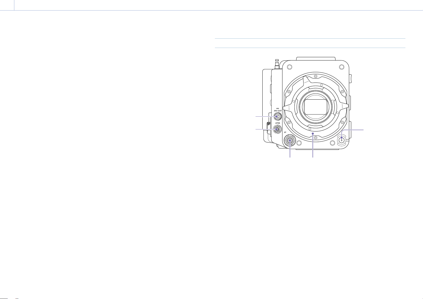
Front
1
23
4
5
1. ASSIGN (assignable) button 3 (page 48)
Assign functions using the EDIT page of the
user functions screen (page 48).
The assigned function toggles between on/off
(enabled/disabled) or is activated with each
press.
2. PL lens mount adaptor (page 21)
3. VF (viewfinder output) connector
(page 24)
4. LENS connector (12-pin)
Supports iris, focus, and zoom control from a
network-connected computer, smartphone, or
tablet.
5. 24V OUT connector (24 V DC output,
Fischer 3-pin)
24 V DC power supply output connector
(page 120).
The output voltage and maximum output
current of this connector vary depending on
the input voltage to the unit. The maximum
current includes the output current from
the 24V OUT connector on the rear panel
(page 12).
11 V to 17 V input
Output voltage: 24 V
Maximum output current: 1.0 A
22 V to 32 V input
Output voltage: Same as the input voltage
Maximum output current: 2.0 A
1. Overview: Location and Function of Parts
12
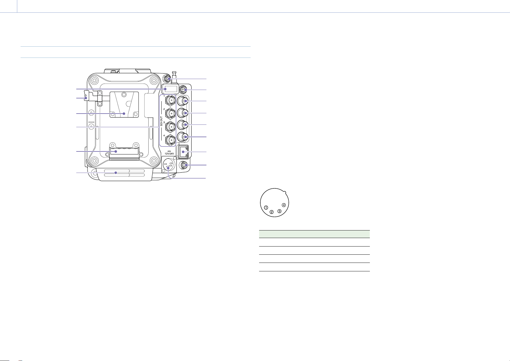
Rear
2
1
3
4
5
6
7
8
9
10
11
12
13
14
Air inlet
[Note]
Do not operate with the air inlet blocked.
1. 24V OUT connector (24 V DC output,
Fischer 3-pin)
24 V DC power supply output connector
(page 120).
The output voltage and maximum output
current of this connector vary depending on
the input voltage to the unit. The maximum
current includes the output current from
the 24V OUT connector on the front panel
(page 11).
11 V to 17 V input
Output voltage: 24 V
Maximum output current: 1.0 A
22 V to 32 V input
Output voltage: Same as the input voltage
Maximum output current: 2.0 A
2.
12V OUT connector (12 V DC output, LEMO
2-pin)
12 V DC power supply output connector
(page 120).
The output voltage and maximum output
current of this connector vary depending on
the input voltage to the unit.
11 V to 17 V input
Output voltage: Same as the input voltage
Maximum output current: 1.0 A
22 V to 32 V input
Output voltage: 16.8 V
Maximum output current: 1.0 A
3. MONITOR OUT connector (BNC type)
HD SDI monitor signal output connector
(page 120).
4. GENLOCK (genlock input) connector (BNC
type)
To genlock the unit to an external source or
to lock the timecode of the unit to an external
source, input an external reference signal.
Digital signal and analog signal input are
supported.
Digital signal: 1.5G HDSDI interlaced/
progressive signal
Analog signal: HD sync, SD sync
5. TC IN (timecode input) connector (BNC
type)
To lock the timecode of the unit to an external
source, input a reference timecode signal.
6. AUX connector (BNC type)
Outputs the timecode signal (page 120).
7. Network connector (RJ-45)
Connect to a wired LAN network using a LAN
cable (not supplied) for remote control of the
unit (page 100).
8. REMOTE (remote control) connector
(8-pin)
Connect to a remote control unit or other
external control device.
9. 12V/24V (DC power input) connector
(page 17)
DC power supply input connector for external
power supply to the unit. Supports 12 V and 24
V input voltages.
No. Signal
1 GND
2 NC
3 NC
4 DC IN (11 V to 17 V or 22 V to 32 V)
10. Battery attachment terminal (page 17)
11. SDI OUT 1 to 4 (serial digital output)
connectors (BNC type) (page 120)
12. Battery pack mount (page 17)
13. Battery release lever (page 17)
14. HDMI OUT connector (page 120)
1. Overview: Location and Function of Parts
13
Top
2 3 4
1
5
1. External device connector
Used for camera wireless remote control
(page 100) by connecting a CBK-WA02
Wireless LAN Adaptor (option).
2. Manufacturer calibration terminal
Manufacturer terminal for calibration and
servicing (cannot be used by users).
3. Release button (page 20)
4. Handle/VF attachment mount
(page 20)
5. Accessory mounting screw holes
Type of screw: 1/4-20UNC (8)
Type of screw: 3/8-16UNC (10)
Length of engagement: 10 mm (
13
/
32
inch) or
less
Bottom
2
1
Air vent
1. Tripod plate attachment holes
Type of screw: 1/4-20UNC (2)
Type of screw: 3/8-16UNC (4)
Length of engagement: 9 mm (
3
/
8
inch) or less
2. SD card slot (page 34)

1. Overview: Location and Function of Parts
14
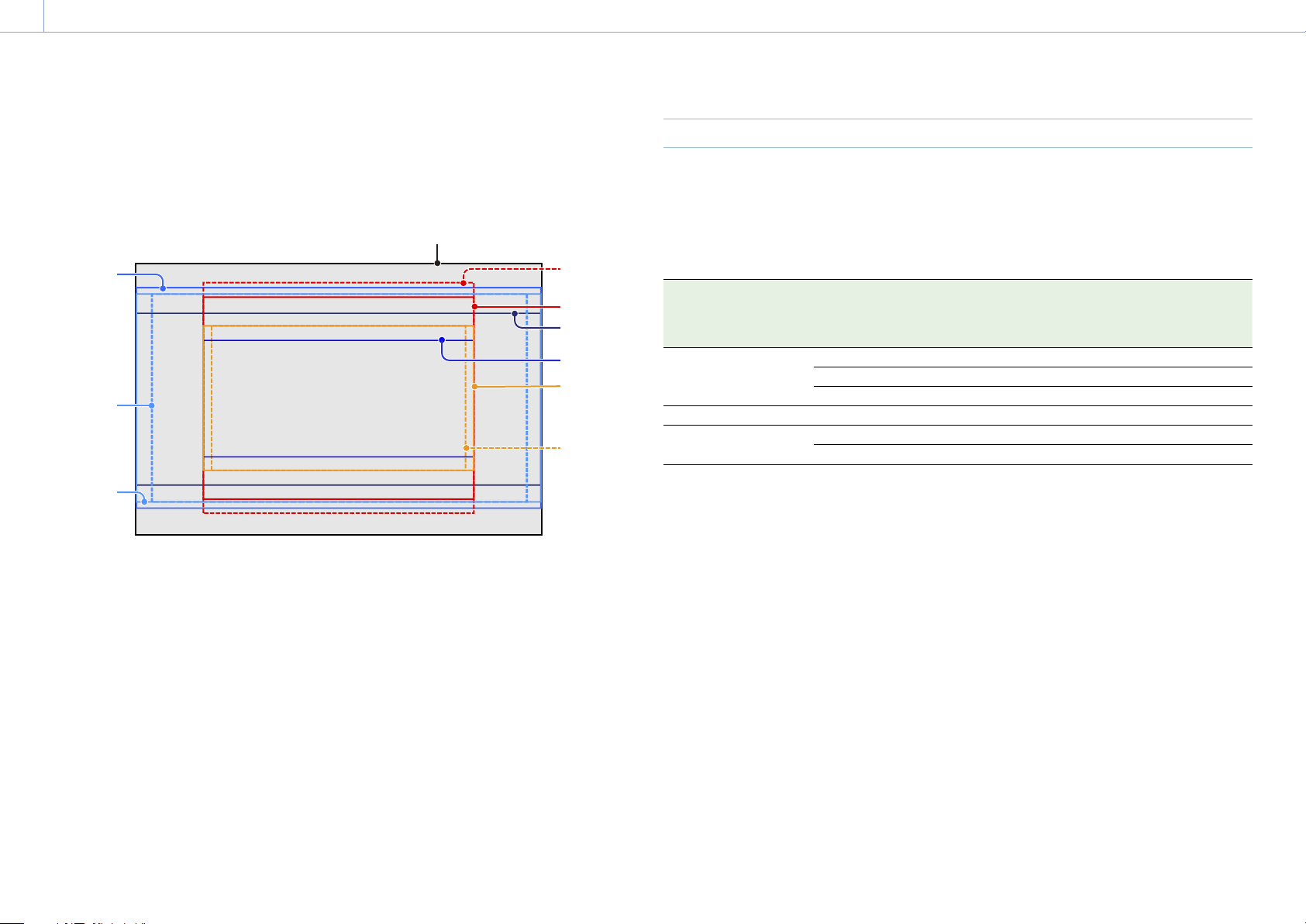
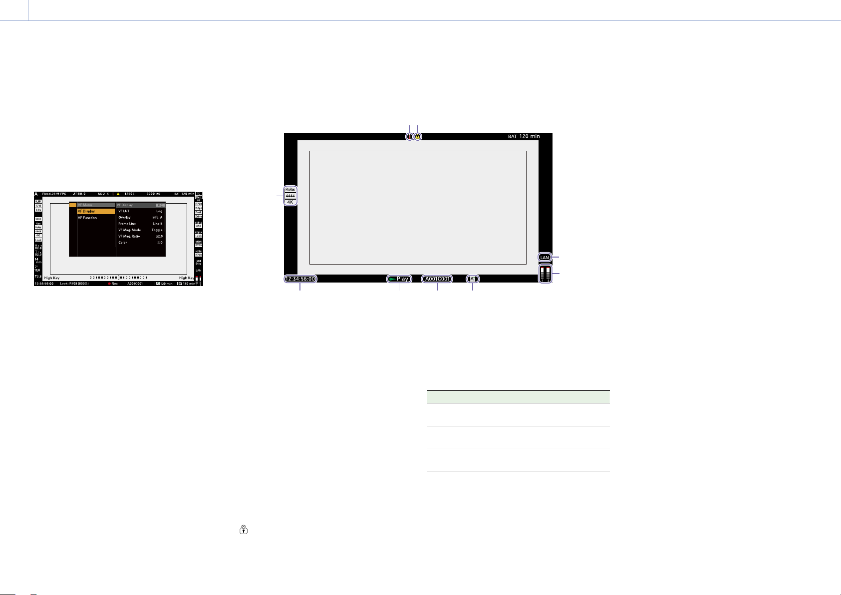
Viewfinder/Monitor Screen
During shooting (recording or standby) and playback, the information selected in Monitoring >
Overlays/Frame Line > Overlay A/B Setup (page 79) in the full menu is displayed.
Information displayed on the screen while recording
29
1 2 3 64 5 7 8
22232526 242728
10
9
11
14
15
16
17
18
19
21
12
13
20
35
30
31
32
34
33
36
37
1. Recording frame rate indicator
Displays the recording frame rate and project
frame rate.
2. Shutter angle/shutter speed indicator
Displays the shutter angle or shutter speed
of the electronic shutter, according to the
Technical > System Configuration (page 87)
setting in the full menu.
3. ND filter indicator
Displays the density of the ND filter. The
display value is a LOG (base 10) value
(page 66).
CLEAR
0.3 (1/2)
0.6 (1/4)
0.9 (1/8)
1.2 (1/16)
1.5 (1/32)
1.8 (1/64)
2.1 (1/128)
2.4 (1/256)
4. Thermometer icon
Displayed when a high temperature warning
message is issued.
The description is displayed in the Info
category in the menu.
5. Warning icon
Displayed when other than a high temperature
warning message is issued.
The description is displayed in the Info
category in the menu.
6. Exposure index (EI)/gain indicator
Displays the EI value, or the gain value (dB
units) set by an RM-B170 or other remote
control unit.
[Note]
The gain value is displayed only when Technical
> Special Configuration > RM/RCP Paint Control
(page 91) is set to On in the full menu.
7. Color temperature indicator
Displays the color temperature and Tint value
of the white balance.
8. Battery capacity/voltage indicator
Displays the following indicators according to
the type of battery power source.
Battery type Display
Sony Info battery Battery remaining capacity
and remaining recording
time
Anton/Bauer
battery
Remaining battery capacity
(% indicator)
Other batteries Input voltage
9. Timecode external lock indicator/Genlock
status indicator
Displays locked status when the timecode is
locked to an external source. Displays locked
status when genlocked.
10. VF LUT indicator
Displays the viewfinder LUT (page 70).
11. VF Double Speed Scan indicator
Displays the on/off state of the function for
doubling the frame rate of the viewfinder
display.
12. VF Peaking indicator
Displays the on/off state of the peaking
function of the viewfinder display.
13. VF Zebra indicator
Displays the on/off state of the zebra function
of the viewfinder display (page 52).
14. SDI OUT 1/2 connector LUT indicator
Displays the LUT setting of the SDI OUT 1/2
connectors (page 68).
15. SDI OUT 3/4 connector LUT indicator
Displays the LUT setting of the SDI OUT 3/4
connectors (page 69).
16. Monitor LUT indicator
Displays the LUT setting of the Monitor output
(page 69).
17. HDMI LUT indicator
Displays the LUT setting of the HDMI output
(page 70).
1. Overview: Location and Function of Parts
15
18. SDI output REC trigger indicator
Displays the SDI output REC trigger status.
State Display
Technical > System Configuration > SDI Rec
Remote Trigger in the full menu
Recording command
superimposed on the SDI output
Off – (Blank)
HD SDI Remote I/F Stop command Top: SDI
Bottom: Stop
Rec command Top: SDI
Bottom: REC
Parallel Rec Stop command Top: SDI-P
Bottom: Stop
Rec command Top: SDI-P
Bottom: REC
19. Network connection status indicator
Displays the network connection status (LAN
or Wi-Fi).
State Display
Disconnected or other error (valid
network connection settings)
Flashing
Connected (valid network connection
settings)
On
Network connection function not
used
Blank
20. High Key/Low Key indicator (Monitor
output)
Displayed when the Monitor output is High
Key (screen for checking blown-out highlights)
or Low Key (screen for checking blocked-out
shadows) (displayed for Monitor Out output).
21. Audio level meter indicators
Displays the levels of audio channels 1 and 2
while recording.
22. Recording media state/remaining
capacity indicator for each media slot
Displays the state and remaining capacity of
the media in AXS memory card slots A/B.
A
(recording active) icon on the left of “AXS”
indicates the recording target media.
An indicator
(active slot icon) on the upper
right of the slot A/B icon on the right of “AXS”
indicates the playback target media (green
indicator indicates media is being played).
A
(warning) icon is displayed for media if a
condition occurs that could impact recording.
23. Spirit level gauge graphical indicator
Displays the horizontal tilt of the unit in ±0.1°
increments, up to ±10°.
You can adjust the zero angle alignment of
the spirit level gauge by executing Technical
> Special Configuration > Level Gauge Adjust
(page 87) in the full menu.
24. Clip name display
Displays the first 8 characters of the name
of the next clip to be recorded in recording
standby mode.
Displays the first 8 characters of the name
of the clip currently being recorded when
recording.
25. Recording status indicator
Displays the following recording operation
states of the unit.
Display Description
Rec
(Rec)
Recording
Stby
(Stby)
Recording standby
Cache
(Cache)
Picture cache recording
standby
CALL
(CALL)
CALL command
incoming
When Monitoring > Overlays/Frame Line > VF,
SDI 1/2, SDI 3/4, Monitor, or HDMI > Overlay
(page 79) is set to Rec Ind. in the full menu,
the information display for the configured
output destination is set to display only the
recording operation status.
26. Look information display
Displays the selected Look
(page 67)
.
27. High Key/Low Key indicator (viewfinder
output)
Displayed when the viewfinder output is High
Key (screen for checking blown-out highlights)
or Low Key (screen for checking blocked-out
shadows) (displayed for viewfinder output).
28. Time data display
Displays the duration or timecode, depending
on the TC/Media category > TC Display setting
in the menu (page 56).
29. Iris position indicator
Displays the iris position (only when a lens
that is compatible with the iris setting display
function is attached).
The iris position indicator displays in 1/3 stop
increments when using an E-mount lens.
[Note]
The F-stop value is displayed instead of the T-stop value
if the T-stop value cannot be obtained.
30. Focus position indicator
Displays the focus position (only when a lens
that is compatible with the focus setting
display function is attached).
31. Zoom position indicator
Displays the focal length of the zoom
(displayed only when a lens that supports the
zoom setting indicator is attached).
32. Spirit level indicator
Displays horizontal level information
numerically.
R (Roll) indicates the left-to-right horizontal tilt
of the unit.
T (Tilt) indicates the front-to-rear vertical tilt of
the unit.
You can adjust the zero angle alignment of
the spirit level gauge by executing Technical
> Special Configuration > Level Gauge Adjust
(page 87) in the full menu.
33. Recording LUT indicator
Displays the LUT setting for recording.
34.
Recording media format (codec) indicator
Displays the format of the recording on an AXS
memory card.
35. Base ISO indicator
Displays the configured base sensitivity.
36. Effective picture size indicator
Displays the effective picture size and whether
anamorphic de-squeeze conversion is applied,
set using Project category > Imager Mode in
the menu. In Surround View mode, a “Sur.V”
icon is displayed below the anamorphic
conversion ratio icon (page 54).
A “Z 17:9” icon is displayed when Project
category > Zoom to Fit (page 55) is set to
17:9 in the menu. A “Z 16:9” icon is displayed
when Zoom to Fit is set to 16:9.
37. Camera ID indicator
Displays the Camera ID setting (page 76).
1. Overview: Location and Function of Parts
16
Menu display and settings on the
viewfinder screen
When a DVF-EL200 is attached to the unit,
press and hold the Menu button on the DVF-
EL200 to display the Monitoring > VF Display
(page 78) and VF Function (page 78)
setup menus on the viewfinder screen. This
allows you to configure these functions while
viewing the viewfinder screen.
Information displayed on the playback screen
The following information is displayed on the playback picture.
98
7
6
1
2
4
53
1. Playback media format (codec) indicator
Displays the recording format (codec) of the
playback clip.
2. Time data display
Displays the duration or timecode, depending
on the TC/Media category > TC Display setting
in the menu (page 56).
3. Playback status indicator
Displays the playback status.
Displays “CALL” when a CALL command is
received.
4. Playback clip name display
Displays the first 8 characters of the name of
the playback clip.
5. Playback media indicator
Displays the type of recording media being
played.
A
(protect) icon appears on the right if the
memory card is write-protected.
6. Audio level meter indicators
Displays the levels of audio channels 1 and 2
during playback.
7. Network connection status indicator
Displays the network connection status (LAN
or Wi-Fi).
State Display
Disconnected or other error (valid
network connection settings)
Flashing
Connected (valid network connection
settings)
On
Network connection function not
used
Blank
8. Thermometer icon
Displayed when a high temperature warning
message is issued.
The description is displayed in the Info
category in the menu.
9. Warning icon
Displayed when other than a high temperature
warning message is issued.
The description is displayed in the Info
category in the menu.

17
2. Preparation
Preparing a Power Supply
You can use a battery pack or AC power via an
AC adaptor.
For safety, use only the Sony battery packs
listed below.
Lithium-ion battery pack
BP-GL95B
AC adaptor
Adaptor that has a rating of 120 W or higher.
Using a Battery Pack
Insert the battery pack into the battery pack
mount (page 12) of the battery adaptor,
then slide the battery pack down to lock it in
place.
To remove it, unlock the battery pack by
sliding it up while pressing the battery release
lever (page 12), then remove it.
[Notes]
• Before use, charge the battery pack with the battery
charger.
• A warm battery pack immediately after use may not
be able to be fully recharged.
• Remove the battery adaptor while supporting the unit
by hand.
Checking the remaining battery charge
When recording or playback is in progress
using the battery pack, the current battery
remaining time and battery voltage are
displayed on the sub display screen
(page 36) and viewfinder/monitor screen
(page 14).
The unit indicates the remaining usage time in
minutes by calculating the available time with
the battery pack if operation is continued at
the current rate of power consumption.
If the remaining battery charge becomes
low
If the remaining battery charge decreases to a
certain level during operation, the remaining
battery capacity indicator flashes and the REC
lamp flashes to warn you.
If the remaining charge further decreases to a
level at which operation cannot be continued,
a battery-empty message appears.
Replace the battery pack with one that is fully
charged.
To change the message levels
Change levels using Technical > Batt./Voltage
Alarm (page 89) in the full menu.
Using AC Power (DC IN Power)
The unit works with AC power using a 120W
AC adaptor.
11V to 17V and 22V to 32V input voltage
ranges are supported.
[Notes]
• When switching to the DC IN power supply during
battery operation, use a power supply with a voltage
in the range 12V to 17V for safer power supply
switching.
• When using a 22V to 32V power supply, it is
recommended that you first set the power switch to
the OFF position before connecting the power supply.
• Do not switch the DC IN power supply voltage
directly from a 11V to 17V power supply to a 22V to
32V power supply, or vice versa. This may cause a
malfunction.
Using a Battery Pack and DC IN
Power Supply Together
Whenever an active power supply is applied
using a battery pack and a DC IN power
supply, the DC IN power supply takes
precedence.
[Note]
When the power supply switches from battery operation
to the DC IN power supply, operation of the unit may
stop if the following occurs.
• Chattering of the connector contacts when inserting
the DC connector
• Voltage drop when switching between power
supplies (more prevalent when the external load is
greater)

2. Preparation
18
Setting the Clock
When you use the unit for the first time, the
initial setup screen appears on the sub display
when the power is turned on.
Set the date and time of the built-in clock
using this display.
Time Zone
The value shows the time difference from UTC
(Coordinated Universal Time). Change the
setting if needed.
[Note]
When Time Zone is changed, the clock setting changes
according to the time difference.
Setting the Date and Time
Turn the MENU dial (page 10) to move the
cursor, then press the MENU dial to set each
menu item. When you press the MENU dial
when the cursor is on “Set,” the setting display
disappears and the clock setting is completed.
After the initial setup screen disappears, you
can change Time Zone and date/time settings
using Maintenance > Clock Set (page 92) in
the full menu.
[Notes]
• If the clock setting is cleared because the backup
battery fully discharged when no power was supplied
(no battery pack and no DC IN connection), the initial
setup display will be displayed when you next turn
the unit on.
• While the initial setup display is shown, no other
operation, except turning the power off, is permitted
until you finish the setting for this display.
2. Preparation
19
Interchanging the Imager Block
You can interchange the imager block.
This section describes the procedure for
interchanging the 8K imager block with the 6K
imager block as an example.
When attaching the 6K imager block, attach
the cover (MPC-3628: accessory, MPC-3626:
attached) for the 6K imager block.
[Note]
Before interchanging the imager block, turn off the
power for at least 10 minutes to allow the unit to cool.
Also, be careful of sharp edges when interchanging the
imager block.
1 Remove the two hex screws on the
bottom and four hex screws on the front,
and remove the 8K imager block.
Imager block
2 Attach the cover for the 6K imager block
with the side with engraved text facing
forward, and tighten with two screws
(tightening torque: 0.19N·m).
Cover for 6K
imager block
[Notes]
• If the cover for the 6K imager block is not
attached, the heat dissipation of the 6K imager
block will become poor.
• Remove the cover for the 6K imager block when
attaching the 8K imager block.
3 Attach the 6K imager block.
Make sure the imager block is straight,
and tighten the six hex screws removed in
step 1 (tightening torque: 1.4N·m).
Rebooting After Interchanging the
Imager Block
When the unit is turned on for the first time
after interchanging the imager block, startup
will take a bit longer because the unit needs
to reload sensor-specific data.
The unit will reboot automatically a few
minutes after being turned on when the
sensor-specific data has finished loading.
2. Preparation
20
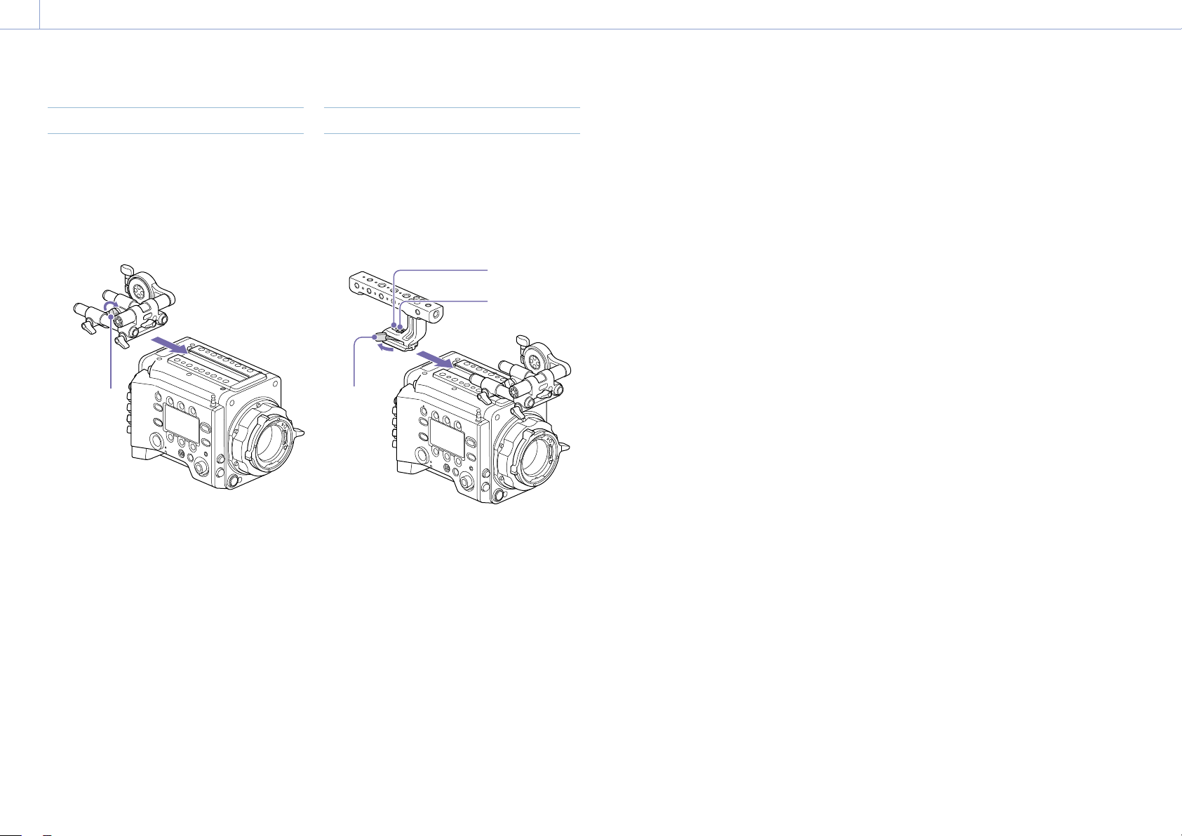
Attaching the VF Attachment
1 Slide the VF attachment on in the
direction of the arrow to attach it.
2 Position the VF attachment in the desired
front/rear position, then turn the lock
lever to secure it in position.
1
2
Lock
lever
[Notes]
• You can also attach the VF attachment in the
front/rear or left/right orientation.
• If the lock lever is difficult to tighten or loosen,
you can use a hex wrench (3mm) on the lock
screw on the top of the lock lever.
To remove the VF attachment
Turn the lock lever to loosen, press the release
button and slide the VF attachment off in the
reverse direction from when attaching it.
Attaching the Handle
1 Slide the handle on in the direction of the
arrow to attach it.
2 Position the handle in the desired front/
rear position, then turn the lock lever to
secure it in position.
2
1
Lock screw
Hex socket
bolt
Lock
lever
[Notes]
• You can also attach a lock screw using a hex
wrench (5 mm) to secure it in position.
• If the lock lever on the handle becomes loose
during use, you can secure the handle by
tightening a hex socket bolt (2 mm) beside the
lock screw.
• You can also attach the handle in the reverse
orientation.
To remove the handle
Turn the lock lever to loosen, press the release
button and slide the handle off in the reverse
direction from when attaching it.
Attaching the VF Attachment and Handle
2. Preparation
21
Recommended PL-mount lens (Super 35mm
size)
SCL-PK6/F, SCL-PK6/M (set of 6 lenses,
20mm/25mm/35mm/50mm/85mm/
135mm)
SCL-PK3/F, SCL-PK3/M (set of 3 lenses,
20mm/25mm/135mm)
SCL-P11X15
Recommended E-mount lens
SELP28135G, SEL1635GM, SEL2470GM,
SEL70200GM, SEL100400GM, SEL1224G,
SEL35F14Z, SEL50F14Z, SEL85F14GM,
SEL90M28G, SEL100F28GM
[Note]
Control may not be supported with some E-mount
lenses. Use a recommended lens.
For details about available lenses for the unit, contact a
Sony service representative.
[CAUTION]
Do not leave the lens facing the sun. Direct
sunlight can enter through the lens, be
focused in the unit, and cause fire.
[Notes]
• Turn the unit off before attaching or removing the
lens and adapter.
• A lens is a precision part. Do not place the lens down
with the mount side facing down. Attach the cap
supplied with the lens.
• The lens interface of the unit is configured by factory
default for an SCL-P11X15 and lenses with Cooke
type connector. To use an SCL-PK6, SCL-PK3, or other
lenses that do not have a Cooke type connector,
set Technical > Lens Configuration > PL-Mt Interface
Position (page 87) to Off in the full menu.
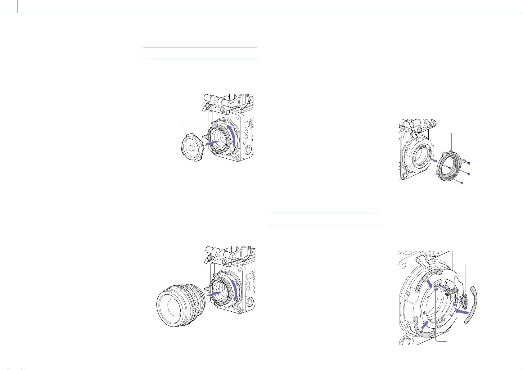
Attaching a PL-Mount Lens
1 Remove the mount cover from the lens
mount by turning the PL-mount lever
counterclockwise.
PL-mount
lever
[Note]
Turn the PL-mount lever counterclockwise to the
stopper position.
2 Insert the lens into the lens mount by
aligning the concave part of the lens with
the positioning pin on the upper right of
the lens mount.
3 Secure the lens by turning the PL-mount
lever clockwise while holding the lens.
[Note]
Do not turn the lens when attaching the PL-mount
lens. It may cause damage to the hot shoe pin.
To attach a Cooke /i lens
Align the contacts on the lens with the hot
shoe of the unit. There are two connectors on
the side of the lens adaptor, and either can be
used.
To remove the lens
1
Turn the PL-mount lever counterclockwise
while holding the lens from underneath.
2 Pull the lens forward.
[Notes]
• If another lens will not be attached soon,
carefully align the concave part of the mount
cover, then secure the mount cover by turning
the PL-mount lever clockwise.
• For correct I/F communication with the lens, set
the Technical > Lens Configuration (page 87)
settings in the full menu to match the lens in
use.
Adjusting the Flange Focal Length
The unit is shipped with the flange focal
length already adjusted. If you need to adjust
the flange focal length, remove the lens
mount, and change the shims with those of
the appropriate thickness. You can adjust the
thickness by ±0.1 mm in 0.01 mm increments.
Shims
The following shims are supplied with the unit.
0.05 mm × 1 (circular)
0.01 mm × 15 (1/3 arc)
1/3 arc shims should always be used as a set
of three shims. Insert shims to increase the
flange focal length. The unit is shipped with
the flange focal length already adjusted using
the following three types of shims.
0.10 mm (circular)
0.05 mm (circular)
0.01 mm (1/3 arc)
A seal is attached showing the shim thickness
when shipped.
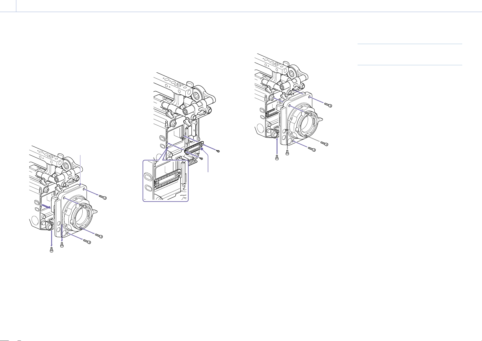
Adjusting the flange focal length
1 Remove the six Torx screws and remove
the PL-mount flange.
1
PL-mount flange
2 Loosen the four Phillips screws on both
sides of the PL connectors (two locations),
and remove the PL connectors and PL
connector plates.
3 Attach shims to the PL-mount adaptor
(three locations).
33
3
3
3
3
2
2
2
2
PL connectors
PL connector
plates
Mounting a Lens and Adjusting the Flange Focal Length
2. Preparation: Mounting a Lens and Adjusting the Flange Focal Length
22
When using 1/3 arc shims
Attach shims so that they have the same
thickness in all three locations.
Shims
When using circular shims
Attach with the surface that has markings
on it facing the front.
Markings
Markings
4 Reattach the PL connectors (two
locations) to their original positions, and
tighten the four Phillips screws with 0.18
N·m tightening torque.
5 Reattach the PL-mount flange in its
original position, and tighten the six Torx
screws to a tightening torque of 0.35 N·m
using a T8 torque wrench.
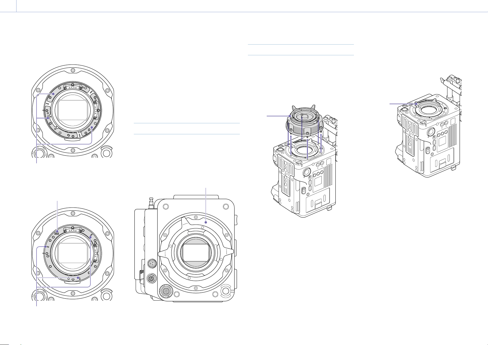
Cleaning the Filter
To clean the filter, first remove the adaptor.
Exercise care when wiping the adaptor
center part (shaded part) with a cloth or
other material to prevent fibers adhering to
surfaces. If fibers are adhering, wipe off using
a soft brush.
Adaptor
Removing the PL Lens Adaptor
Remove the PL lens adaptor when you
want to mount an E-mount lens to the unit.
Attachment/removal is performed with the
rear side of the unit facing down.
Loosen the six hex screws (2.5mm) and
remove the PL lens adaptor.
PL lens
adaptor
[Notes]
• Removing the battery and placing the rear side of the
unit face down provides stability.
• When attaching/removing the adaptor, take care not
to touch the connector contacts of the unit and PL
lens adaptor.
To attach the PL lens adaptor
1 Check that the mount lever is in the
locked position.
Mount
lever
2 Place the PL lens adaptor back in its
original position, insert the six hex screws
(2.5mm), and tighten the screws to a
tightening torque of 0.8 ± 0.12 N·m using
a hex wrench (2.5mm).

2. Preparation: Mounting a Lens and Adjusting the Flange Focal Length
23
Attaching an E-Mount Lens
1 Remove the PL lens adaptor (page 22).
2 Push the lock switch up, and turn the
mount lever clockwise to release the lock.
Mount lever
Lock switch
3 Align the mounting marks (white) on the
unit and lens mount, and then push the
lens into the mount.
4 Secure the lens by turning the mount
lever counterclockwise while holding the
lens.
Mounting marks
(white)
[Note]
When an E-mount lens is connected, operation using a
12-pin lens connector is not guaranteed.
To remove the lens
1 Push the lock switch up, and turn the
mount lever clockwise to release the lock.
2 Pull the lens forward.
[Note]
If another lens will not be attached soon, carefully
align the concave part of the mount cover, then
secure the mount cover by turning the mount lever
counterclockwise.
2. Preparation
24
Attaching a Viewfinder
Available viewfinders for the unit
DVF-EL200: OLED color viewfinder
Viewfinders are available separately.
This section describes attachment of the
DVF-EL200 as an example.
For details about attaching each viewfinder, refer to the
operating instructions of the viewfinder.
[CAUTION]
Do not leave the unit with the eyepiece of the
viewfinder facing the sun. Direct sunlight can
enter through the eyepiece, be focused in the
viewfinder, and cause fire.
[Notes]
Attach/remove the viewfinder while the unit is turned
off.
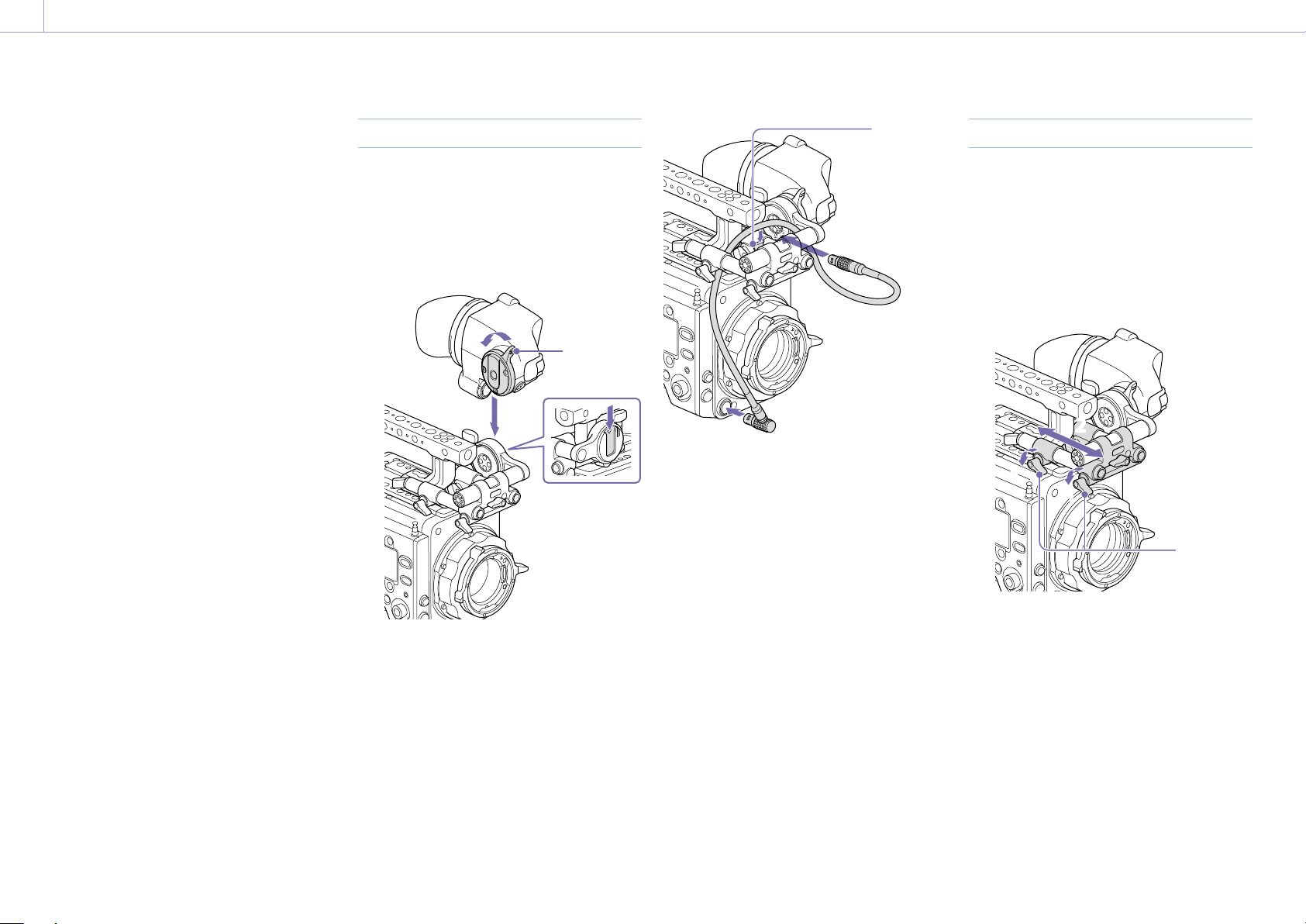
Attaching a Viewfinder
1 Align the viewfinder shoe with the groove
of the viewfinder mount on the VF
attachment, and attach the viewfinder.
2 Turn the viewfinder lock lever in the LOCK
direction to secure it in position.
2
1
Lock lever
3 Connect the viewfinder and unit using the
VF connection cable.
Viewfinder side:
Position the connector with the mark (red)
at the top, and fully insert the connector.
Camera side:
Alight the concave part of the VF
connector with the connector mark (red),
and fully insert the connector.
Clamper
[Note]
Secure the cable in the clamper as required.
To remove the viewfinder
1
Disconnect the VF connection cable from
the viewfinder and unit.
2 Turn the lock lever in the direction
opposite to LOCK, then remove the
viewfinder from the VF attachment.
Adjusting the Viewfinder Position
To adjust the front/rear position
1 Loosen one or both of the front/rear rod
lock levers of the VF attachment.
2 Slide the VF attachment forward/rearward
to adjust the viewfinder position.
11
11
2
2
Rod lock
levers
3 Tighten the rod lock levers.
[Note]
If a rod lock lever is difficult to turn, pull the lever
out, turn it to a position where it is easier to
operate, and then push the lever back in.
2. Preparation: Attaching a Viewfinder
25
To adjust the left/right position and
height (angle)
1 Loosen the rod lock lever at the front of
the VF attachment.
2 Slide the VF attachment rod left/right and
turn the rod up/down to adjust the
viewfinder position.
11
2
2
2
2
Lock screw
Rod lock
lever
3 Tighten the rod lock lever.
[Note]
When the rod lock lever is loosened, adjust the lock
screw using a hex wrench (3mm) to prevent the
viewfinder from falling down.
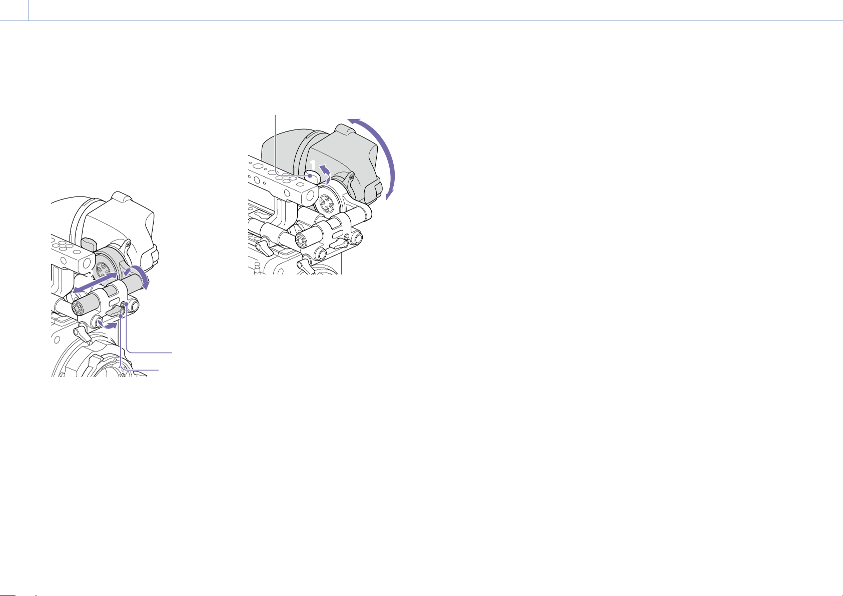
To adjust the viewfinder angle
You can adjust the angle of the viewfinder
while shooting.
1 Loosen the rotation lock lever on the
viewfinder mount.
2 Turn the viewfinder up/down to adjust
the angle.
11
2
2
Rotation lock lever
3 Tighten the rotation lock lever.

2. Preparation
26
This unit records audio and video on AXS
memory cards (optional) loaded in the card
slots.
About AXS Memory Cards
Use the following Sony AXS memory cards
with this unit.
S24
AXS-A1TS24 (1TB/2.4Gbps)
AXS-A256S24 (256GB/2.4Gbps)
AXS-A512S24 (512GB/2.4Gbps)
S48
AXS-A1TS48 (1TB/4.8Gbps)
AXS-A512S48 (512GB/4.8Gbps)
S66
AXS-A1TS66 (1TB/6.6Gbps)
Inserting an AXS Memory Card
1 Open the cover of the card slot block
(page 10).
2 Insert the AXS memory card into the slot
with the label facing to the right.
The ACCESS lamp (page 9) lights in
red then changes to green once the
memory card is ready for use.
3 Close the cover.
ACCESS lamp status
Card slots A and B each have an ACCESS lamp
that indicate the slot status.
Lamp Slot status
Lights in red Accessing the AXS memory
card (writing/reading data)
Lights in green Standby (ready for recording
or playback using the AXS
memory card)
Off
• No AXS memory card is
loaded.
• The loaded card is invalid.
• An AXS memory card is
loaded, but the other slot is
selected.
Removing an AXS Memory Card
1 Open the cover of the card slot block.
2 Pull out the AXS memory card.
[Note]
Data integrity is not guaranteed if the power is turned
off or a memory card is removed while it is being
accessed. Data on the card may be destroyed. Be sure
that its ACCESS lamp is lit in green or off when you turn
off the power or remove a memory card.
Switching Between AXS Memory
Cards
When AXS memory cards are loaded in both
slot A and slot B, you can press the SLOT
SELECT button (page 9) to select the
memory card to use.
If a card becomes full, recording continues
after automatically switching to the second
card.
[Note]
The SLOT SELECT button is disabled while recording/
playback is in progress. The memory cards are not
switched even if you press the button.
Formatting (Initializing) an AXS
Memory Card
When an unformatted AXS memory card or
an AXS memory card formatted in another
specification is loaded, a message notifying
you that the media has a different file system
appears. In this case, format the memory card
using the following procedure.
1 Select TC/Media category > Format Media
in the menu.
2 Select AXS Slot A (slot A) or AXS Slot B
(slot B), then press the MENU dial.
A confirmation screen prompting whether
to format the card appears.
3 Press and hold ITEM key 1 and ITEM key 3
for 3 seconds to execute formatting.
Formatting starts, a message is displayed
during execution, and the ACCESS lamp
lights in red.
When formatting ends, a completion
message appears. Press the MENU dial to
dismiss the message.
If formatting fails
A write-protected AXS memory card or
memory card that cannot be used with this
unit will not be formatted.
A warning message is displayed. Replace the
card with an appropriate AXS memory card,
according to the instructions in the message.
[Note]
All the data, including recorded pictures and setup files,
are erased when a memory card is formatted.
Handling AXS Memory Cards

2. Preparation: Handling AXS Memory Cards
27
Checking the Remaining
Recording Time
While shooting (recording or standby), you
can check the remaining capacity on the AXS
memory cards loaded in each slot using the
recording media remaining capacity indicator
on the Home screen of the sub display
(page 36) or the viewfinder/monitor screen
(page 14).
The available time for recording with the
current video format (recording bit rate) is
calculated according to the remaining space
on each card and displayed in time units of
minutes.
[Note]
A (protect) icon appears if a memory card is write-
protected.
Exchanging an AXS memory card
• If the total remaining time on the inserted
memory cards during recording becomes
less than the time set using Technical
> Alerts & Tally > Media Near Full Alarm
(page 89) in the full menu, the remaining
media capacity indicator flashes, the REC
lamp flashes, and a beep sound is emitted
to warn you. Replace the cards with those
that have sufficient space.
• If you continue recording, the message
“Media Full” appears, and recording stops
when the total remaining recording time
falls to 0.
[Notes]
• The maximum number of clips that can be recorded
on a single AXS memory card is given below.
S24/S48: Approximately 600
S66: Approximately 430 to 440
• The display of remaining recording time changes to
“0” and the message “Media Full” appears when the
clip limit is reached.
Restoring an AXS Memory Card
If for any reason an error should occur in
a memory card, the card must be restored
before use.
If an AXS memory card that needs to be
restored is loaded, a message prompting you
to execute the restore operation is displayed
on the sub display.
To start the restore process, select Run by
turning the MENU dial, then press the MENU
dial.
The restoration starts.
During execution, a message is displayed and
the ACCESS lamp lights in red.
When restoration ends, a completion message
appears. Press the MENU dial to dismiss the
message.
If restoration fails
• A write-protected AXS memory card or
one on which an error occurred cannot
be restored. For such a card, a warning
message is displayed. Release the write
protection or replace the AXS card,
according to the instructions in the
message.
• An AXS memory card on which an error
occurred may become usable again when
reformatted.
• In some cases, some clips can be restored
while others cannot. Playback of the
restored clips becomes possible again.
[Note]
For restoration of media recorded with this unit, be sure
to use this unit.
Media recorded with a device other than this unit or
with another unit of different version (even of the same
model) may not be restored using this unit.

2. Preparation: Handling AXS Memory Cards
28
Recording to an AXS Memory Card
You can select the format for recording to an AXS memory card using Project category > Recording Format (page 54) in the menu.
During AXS standalone recording, recording automatically switches to the second AXS memory card when the first card becomes full.
If using an S24, S48, or S66 AXS memory card, the following restrictions apply depending on the Recording Format and Imager Mode settings. If an S24 or S48 AXS memory card is detected for a
setting where S24 or S48 AXS memory cards are not supported, a warning message is displayed prompting you to use an S66 AXS memory card.
MPC-3628
Recording
Format
Imager Mode Shooting frame rate and S24/S48/S66 AXS memory card support
24 25 30 48 50 60 66 72 75 88 90 96 100 110 120
X-OCN XT 8.6K 3:2 S66 S66 S66 – – – – – – – – – – – –
8.2K 17:9
7.6K 16:9
S48/S66 S48/S66 S48/S66 –
1)
–
1)
–
1)
– – – – – – – – –
5.8K 6:5 S48/S66 S48/S66 S48/S66 S66 – – – – – – – – – – –
5.8K 17:9
5.4K 16:9
S24/S48/
S66
S24/S48/
S66
S24/S48/
S66
S48/S66 S48/S66 S48/S66 S66 S66 S66 –
1)
–
1)
– – – –
X-OCN ST 8.6K 3:2 S48/S66 S48/S66 S48/S66 – – – – – – – – – – – –
8.2K 17:9
7.6K 16:9
S48/S66 S48/S66 S48/S66 S66 S66 S66 – – – – – – – – –
5.8K 6:5 S24/S48/
S66
S24/S48/
S66
S48/S66 S48/S66 – – – – – – – – – – –
5.8K 17:9
5.4K 16:9
S24/S48/
S66
S24/S48/
S66
S24/S48/
S66
S48/S66 S48/S66 S48/S66 S48/S66 S48/S66 S48/S66 S66 S66 – – – –
X-OCN LT 8.6K 3:2 S24/S48/
S66
S24/S48/
S66
S48/S66 – – – – – – – – – – – –
8.2K 17:9
7.6K 16:9
S24/S48/
S66
S24/S48/
S66
S24/S48/
S66
S48/S66 S48/S66 S48/S66 – – – – – – – – –
5.8K 6:5 S24/S48/
S66
S24/S48/
S66
S24/S48/
S66
S24/S48/
S66
– – – – – – – – – – –
5.8K 17:9
5.4K 16:9
S24/S48/
S66
S24/S48/
S66
S24/S48/
S66
S24/S48/
S66
S24/S48/
S66
S24/S48/
S66
S24/S48/
S66
S24/S48/
S66
S24/S48/
S66
S48/S66 S48/S66 – – – –
4K ProRes
4444
8.2K 17:9 S24/S48/
S66
S24/S48/
S66
S24/S48/
S66
S48/S66 S48/S66 S48/S66 – – – – –
– – – –
5.8K 6:5 S24/S48/
S66
S24/S48/
S66
S24/S48/
S66
S48/S66 – – – – – – – – – – –
5.8K 17:9 S24/S48/
S66
S24/S48/
S66
S24/S48/
S66
S48/S66 S48/S66 S48/S66 – – – – – – – – –
2. Preparation: Handling AXS Memory Cards
29
Recording
Format
Imager Mode Shooting frame rate and S24/S48/S66 AXS memory card support
24 25 30 48 50 60 66 72 75 88 90 96 100 110 120
4K ProRes
422 HQ
8.2K 17:9 S24/S48/
S66
S24/S48/
S66
S24/S48/
S66
S24/S48/
S66
S24/S48/
S66
S24/S48/
S66
– – – – – – – – –
5.8K 6:5 S24/S48/
S66
S24/S48/
S66
S24/S48/
S66
S24/S48/
S66
– – – – – – – – – – –
5.8K 17:9 S24/S48/
S66
S24/S48/
S66
S24/S48/
S66
S24/S48/
S66
S24/S48/
S66
S24/S48/
S66
S24/S48/
S66
S48/S66 S48/S66 – – – – – –
QFHD
ProRes
4444
7.6K 16:9 S24/S48/
S66
S24/S48/
S66
S24/S48/
S66
S24/S48/
S66
S24/S48/
S66
S48/S66 – – – – – – – – –
5.4K 16:9 S24/S48/
S66
S24/S48/
S66
S24/S48/
S66
S24/S48/
S66
S24/S48/
S66
S48/S66 – – – – – – – – –
QFHD
ProRes 422
HQ
7.6K 16:9 S24/S48/
S66
S24/S48/
S66
S24/S48/
S66
S24/S48/
S66
S24/S48/
S66
S24/S48/
S66
– – – – – – – – –
5.4K 16:9 S24/S48/
S66
S24/S48/
S66
S24/S48/
S66
S24/S48/
S66
S24/S48/
S66
S24/S48/
S66
S24/S48/
S66
S24/S48/
S66
S24/S48/
S66
– – – – – –
1) When using S66 AXS memory cards, recording is supported by changing the recording format to X-OCN ST or LT. When using S48 AXS memory cards, recording is supported by changing the recording format to X-OCN LT.
2. Preparation: Handling AXS Memory Cards
30
MPC-3626
Recording
Format
Imager Mode Shooting frame rate and S24/S48/S66 AXS memory card support
24 25 30 48 50 60 66 72 75 88 90 96 100 110 120
X-OCN XT 6K 3:2 S48/S66 S48/S66 S48/S66 S66 S66 S66 – – – – – – – – –
6K 1.85:1 S24/S48/
S66
S24/S48/
S66
S48/S66 S48/S66 S48/S66 S66 S66 S66 – – – – – – –
6K 17:9
5.7K 16:9
S24/S48/
S66
S24/S48/
S66
S48/S66 S48/S66 S48/S66 S66 S66 S66 – – – – – – –
6K 2.39:1 S24/S48/
S66
S24/S48/
S66
S24/S48/
S66
S48/S66 S48/S66 S48/S66 S48/S66 S66 S66 S66 S66 – – – –
4K 6:5 S24/S48/
S66
S24/S48/
S66
S24/S48/
S66
S48/S66 S48/S66 S48/S66 S48/S66 S48/S66 – – – – – – –
4K 4:3
Surround View
S24/S48/
S66
S24/S48/
S66
S24/S48/
S66
– – – – – – – – – – – –
4K 4:3 S24/S48/
S66
S24/S48/
S66
S24/S48/
S66
S48/S66 S48/S66 S48/S66 S48/S66 S48/S66 S48/S66 – – – – – –
4K 17:9
Surround View
3.8K 16:9
Surround View
S24/S48/
S66
S24/S48/
S66
S24/S48/
S66
S24/S48/
S66
– – – – – – – – – – –
4K 17:9
3.8K 16:9
S24/S48/
S66
S24/S48/
S66
S24/S48/
S66
S24/S48/
S66
S24/S48/
S66
S24/S48/
S66
S48/S66 S48/S66 S48/S66 S48/S66 S48/S66 S48/S66 S48/S66 S48/S66 –
4K 2.39:1 S24/S48/
S66
S24/S48/
S66
S24/S48/
S66
S24/S48/
S66
S24/S48/
S66
S24/S48/
S66
S24/S48/
S66
S24/S48/
S66
S24/S48/
S66
S48/S66 S48/S66 S48/S66 S48/S66 S48/S66 S48/S66
2. Preparation: Handling AXS Memory Cards
31
Recording
Format
Imager Mode Shooting frame rate and S24/S48/S66 AXS memory card support
24 25 30 48 50 60 66 72 75 88 90 96 100 110 120
X-OCN ST 6K 3:2 S24/S48/
S66
S24/S48/
S66
S24/S48/
S66
S48/S66 S48/S66 S48/S66 – – – – – – – – –
6K 1.85:1 S24/S48/
S66
S24/S48/
S66
S24/S48/
S66
S48/S66 S48/S66 S48/S66 S48/S66 S48/S66 – – – – – – –
6K 17:9
5.7K 16:9
S24/S48/
S66
S24/S48/
S66
S24/S48/
S66
S48/S66 S48/S66 S48/S66 S48/S66 S48/S66 – – – – – – –
6K 2.39:1 S24/S48/
S66
S24/S48/
S66
S24/S48/
S66
S24/S48/
S66
S24/S48/
S66
S48/S66 S48/S66 S48/S66 S48/S66 S48/S66 S48/S66 – – – –
4K 6:5 S24/S48/
S66
S24/S48/
S66
S24/S48/
S66
S24/S48/
S66
S24/S48/
S66
S48/S66 S48/S66 S48/S66 – – – – – – –
4K 4:3
Surround View
S24/S48/
S66
S24/S48/
S66
S24/S48/
S66
– – – – – –
– – – – – –
4K 4:3 S24/S48/
S66
S24/S48/
S66
S24/S48/
S66
S24/S48/
S66
S24/S48/
S66
S24/S48/
S66
S48/S66 S48/S66 S48/S66 – – – – – –
4K 17:9
Surround View
3.8K 16:9
Surround View
S24/S48/
S66
S24/S48/
S66
S24/S48/
S66
S24/S48/
S66
– – – – – – – – – – –
4K 17:9
3.8K 16:9
S24/S48/
S66
S24/S48/
S66
S24/S48/
S66
S24/S48/
S66
S24/S48/
S66
S24/S48/
S66
S24/S48/
S66
S24/S48/
S66
S24/S48/
S66
S24/S48/
S66
S24/S48/
S66
S48/S66 S48/S66 S48/S66 –
4K 2.39:1 S24/S48/
S66
S24/S48/
S66
S24/S48/
S66
S24/S48/
S66
S24/S48/
S66
S24/S48/
S66
S24/S48/
S66
S24/S48/
S66
S24/S48/
S66
S24/S48/
S66
S24/S48/
S66
S24/S48/
S66
S24/S48/
S66
S24/S48/
S66
S48/S66

2. Preparation: Handling AXS Memory Cards
32
Recording
Format
Imager Mode Shooting frame rate and S24/S48/S66 AXS memory card support
24 25 30 48 50 60 66 72 75 88 90 96 100 110 120
X-OCN LT 6K 3:2 S24/S48/
S66
S24/S48/
S66
S24/S48/
S66
S24/S48/
S66
S24/S48/
S66
S48/S66 – – – – – – – – –
6K 1.85:1 S24/S48/
S66
S24/S48/
S66
S24/S48/
S66
S24/S48/
S66
S24/S48/
S66
S24/S48/
S66
S24/S48/
S66
S48/S66 – – – – – – –
6K 17:9
5.7K 16:9
S24/S48/
S66
S24/S48/
S66
S24/S48/
S66
S24/S48/
S66
S24/S48/
S66
S24/S48/
S66
S24/S48/
S66
S48/S66 – – – – – – –
6K 2.39:1 S24/S48/
S66
S24/S48/
S66
S24/S48/
S66
S24/S48/
S66
S24/S48/
S66
S24/S48/
S66
S24/S48/
S66
S24/S48/
S66
S24/S48/
S66
S24/S48/
S66
S48/S66 – – – –
4K 6:5 S24/S48/
S66
S24/S48/
S66
S24/S48/
S66
S24/S48/
S66
S24/S48/
S66
S24/S48/
S66
S24/S48/
S66
S24/S48/
S66
– – – – – – –
4K 4:3
Surround View
S24/S48/
S66
S24/S48/
S66
S24/S48/
S66
– – – – – – – – – – – –
4K 4:3 S24/S48/
S66
S24/S48/
S66
S24/S48/
S66
S24/S48/
S66
S24/S48/
S66
S24/S48/
S66
S24/S48/
S66
S24/S48/
S66
S24/S48/
S66
– – – – – –
4K 17:9
Surround View
3.8K 16:9
Surround View
S24/S48/
S66
S24/S48/
S66
S24/S48/
S66
S24/S48/
S66
– – – – – – – – – – –
4K 17:9
3.8K 16:9
S24/S48/
S66
S24/S48/
S66
S24/S48/
S66
S24/S48/
S66
S24/S48/
S66
S24/S48/
S66
S24/S48/
S66
S24/S48/
S66
S24/S48/
S66
S24/S48/
S66
S24/S48/
S66
S24/S48/
S66
S24/S48/
S66
S24/S48/
S66
–
4K 2.39:1 S24/S48/
S66
S24/S48/
S66
S24/S48/
S66
S24/S48/
S66
S24/S48/
S66
S24/S48/
S66
S24/S48/
S66
S24/S48/
S66
S24/S48/
S66
S24/S48/
S66
S24/S48/
S66
S24/S48/
S66
S24/S48/
S66
S24/S48/
S66
S24/S48/
S66
4K ProRes
4444
6K 17:9 S24/S48/
S66
S24/S48/
S66
S24/S48/
S66
S48/S66 S48/S66 S48/S66 – – – – – – – – –
6K 2.39:1 S24/S48/
S66
S24/S48/
S66
S24/S48/
S66
S48/S66 S48/S66 S48/S66 – – – – – – – – –
4K 6:5 S24/S48/
S66
S24/S48/
S66
S24/S48/
S66
S48/S66 S48/S66 S48/S66 – – – – – – – – –
4K 17:9
Surround View
S24/S48/
S66
S24/S48/
S66
S24/S48/
S66
S48/S66 – – – – – – – – – – –
4K 17:9 S24/S48/
S66
S24/S48/
S66
S24/S48/
S66
S48/S66 S48/S66 S48/S66 – – – – – – – – –
4K 2.39:1 S24/S48/
S66
S24/S48/
S66
S24/S48/
S66
S48/S66 S48/S66 S48/S66 – – – – – – – – –

2. Preparation: Handling AXS Memory Cards
33
Recording
Format
Imager Mode Shooting frame rate and S24/S48/S66 AXS memory card support
24 25 30 48 50 60 66 72 75 88 90 96 100 110 120
4K ProRes
422 HQ
6K 17:9 S24/S48/
S66
S24/S48/
S66
S24/S48/
S66
S24/S48/
S66
S24/S48/
S66
S24/S48/
S66
S24/S48/
S66
S48/S66 – – – – – – –
6K 2.39:1 S24/S48/
S66
S24/S48/
S66
S24/S48/
S66
S24/S48/
S66
S24/S48/
S66
S24/S48/
S66
S24/S48/
S66
S48/S66 S48/S66 – – – – – –
4K 6:5 S24/S48/
S66
S24/S48/
S66
S24/S48/
S66
S24/S48/
S66
S24/S48/
S66
S24/S48/
S66
S24/S48/
S66
S48/S66 – – – – – – –
4K 17:9
Surround View
S24/S48/
S66
S24/S48/
S66
S24/S48/
S66
S24/S48/
S66
– – – – – – – – – – –
4K 17:9 S24/S48/
S66
S24/S48/
S66
S24/S48/
S66
S24/S48/
S66
S24/S48/
S66
S24/S48/
S66
S24/S48/
S66
S48/S66 S48/S66 S48/S66 S48/S66 – – – –
4K 2.39:1 S24/S48/
S66
S24/S48/
S66
S24/S48/
S66
S24/S48/
S66
S24/S48/
S66
S24/S48/
S66
S24/S48/
S66
S48/S66 S48/S66 S48/S66 S48/S66 – – – –
QFHD
ProRes
4444
5.7K 16:9 S24/S48/
S66
S24/S48/
S66
S24/S48/
S66
S24/S48/
S66
S24/S48/
S66
S48/S66 – – – – – – – – –
3.8K 16:9
Surround View
S24/S48/
S66
S24/S48/
S66
S24/S48/
S66
S24/S48/
S66
– – – – – – – – – – –
3.8K 16:9 S24/S48/
S66
S24/S48/
S66
S24/S48/
S66
S24/S48/
S66
S24/S48/
S66
S48/S66 – – – – – – – – –
QFHD
ProRes 422
HQ
5.7K 16:9 S24/S48/
S66
S24/S48/
S66
S24/S48/
S66
S24/S48/
S66
S24/S48/
S66
S24/S48/
S66
S24/S48/
S66
S24/S48/
S66
– – – – – – –
3.8K 16:9
Surround View
S24/S48/
S66
S24/S48/
S66
S24/S48/
S66
S24/S48/
S66
– – – – – – – –
– – –
3.8K 16:9 S24/S48/
S66
S24/S48/
S66
S24/S48/
S66
S24/S48/
S66
S24/S48/
S66
S24/S48/
S66
S24/S48/
S66
S24/S48/
S66
S24/S48/
S66
S48/S66 S48/S66 – – – –

2. Preparation
34
Handling SD Cards for Saving Configuration Data
You can store the configuration file of the
camera on an SD card (optional). The stored
file can be loaded from the SD card.
Supported SD Cards
SDXC memory cards* (File System: exFAT,
Speed Class: 4 to 10, non-UHS, Capacity: 64GB
to 2TB)
SDHC memory cards* (File System: FAT32,
Speed Class: 4 to 10, non-UHS, Capacity: 4GB
to 32GB)
SD memory cards* (File System: FAT16,
Capacity: up to 2GB)
* Referred to as “SD cards” in this manual.
Inserting an SD Card
Insert an SD card into the SD card slot
(page 13).
The ACCESS lamp (page 11) lights in red
then changes to green once the memory card
is ready for use.
ACCESS lamp status
Lamp Slot status
Lights in red Accessing the SD card
(writing/reading data)
Off
• No SD card is loaded.
• The loaded card is invalid.
Removing an SD Card
Press the SD card in slightly, then remove the
card.
[Notes]
• Data integrity is not guaranteed if the power is turned
off or a memory card is removed while it is being
accessed. Data on the card may be destroyed. Be sure
that its ACCESS lamp is lit in green or off when you
turn off the power or remove a memory card.
• Make sure that the card does not pop out when
inserting or removing it.
Formatting (Initializing) an SD
Card
SD cards must be formatted the first time they
are used in the unit.
SD cards for use in the unit should be
formatted using the format function of the
unit. It is also necessary to format an SD
memory card if a caution message is displayed
when the card is loaded.
If an SD card that was formatted in an
unsupported format is loaded in the unit, a file
system mismatch message is displayed.
1 Select TC/Media category > Format Media
> SD Card in the menu, then press the
MENU dial.
A confirmation screen prompting whether
to format the card appears.
2 Press and hold ITEM key 1 and ITEM key 3
for 3 seconds to execute formatting.
Formatting starts, a message is displayed
during execution, and the ACCESS lamp
lights in red.
When formatting ends, a completion
message appears. Press the MENU dial to
dismiss the message.
[Note]
All data is erased when an SD card is formatted, and the
data cannot be restored.
To use media formatted with this unit in
the slots of other devices
Make a backup of the media, then format it
using the other device.
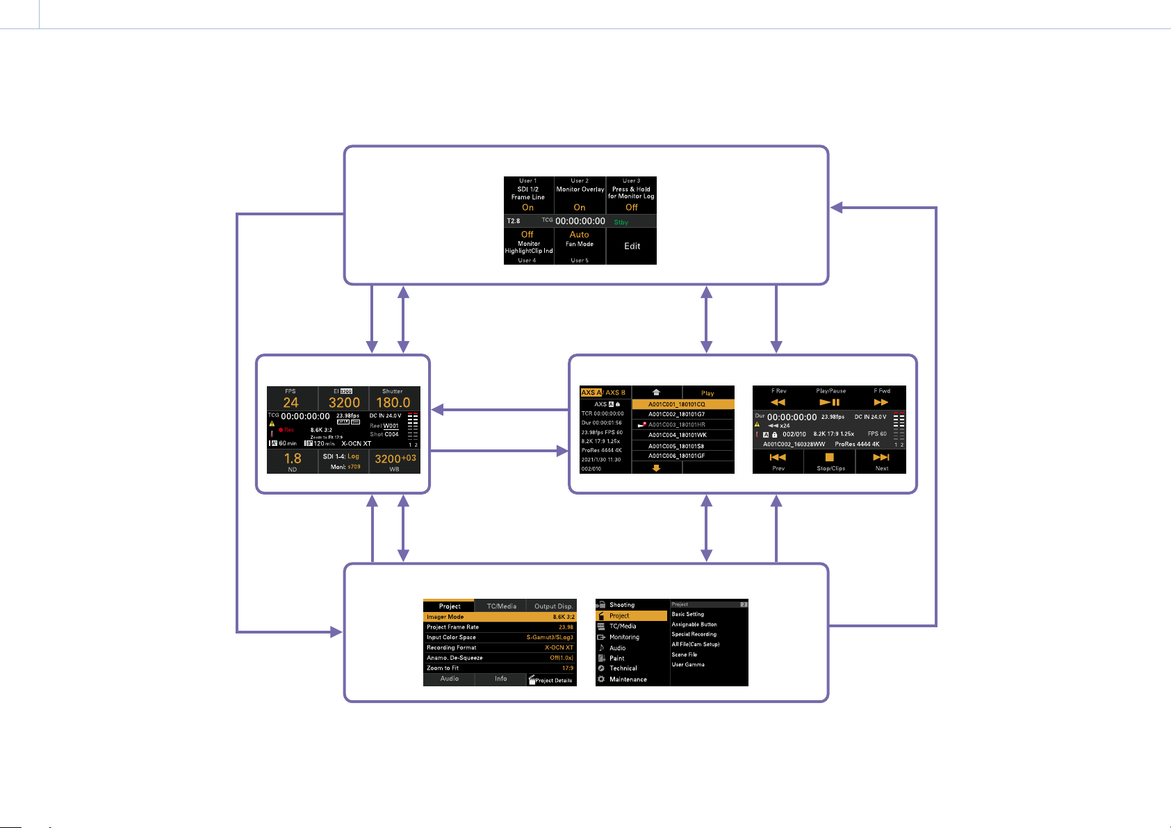
35
3. Camera Operations
Sub Display
The sub display displays the Home screen, clip list screen, playback screen, menu screen, full menu screen, and user functions screen.
You can switch between the screens on the sub display using the buttons on the Assistant side of the unit.
User functions screen
Home screen
Clip list screen
Menu screen Full menu screen
Playback screen
USER button
USER button
MENU button
HOME button
HOME button
HOME button
CLIPS button
CLIPS button
CLIPS button
USER button
MENU button
MENU button
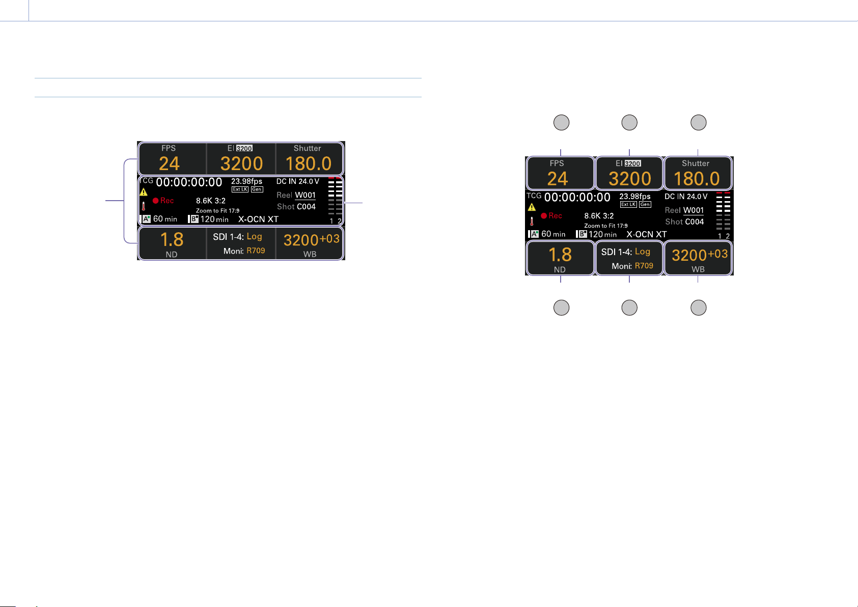
3. Camera Operations: Sub Display
36
Home Screen
Press the HOME button on the Assistant side to display the Home screen. You can check the
status of the unit and set basic settings for the unit on the Home screen.
Item name/
Setting value/
Function display
area
Status
display
area
Item name/Setting value/Function display area
1 2 3
4 5 6
ITEM key 4 ITEM key 5 ITEM key 6
ITEM key 3ITEM key 2ITEM key 1
[Note]
The areas labeled 1 to 6 correspond to ITEM keys 1
to 6 (page 48). Press an ITEM key to select the
corresponding item. The ITEM keys for functions
displayed in orange text color are enabled.
1. FPS
Displays and sets the video frame rate.
2. Exposure Index/Gain
Displays and sets the exposure index (EI) or
the gain set by an RM-B170 or other remote
control unit (top icon displays the base
sensitivity).
[Note]
The gain value is displayed only when Technical
> Special Configuration > RM/RCP Paint Control
(page 91) is set to On in the full menu.
3. Shutter
Displays and sets the shutter speed/shutter
angle of the electronic shutter.
4. ND Filter
Displays and sets the ND filter position.
5. LUT
Displays and sets the monitor LUT.
6. WB (White Balance)
Displays and sets the white balance.
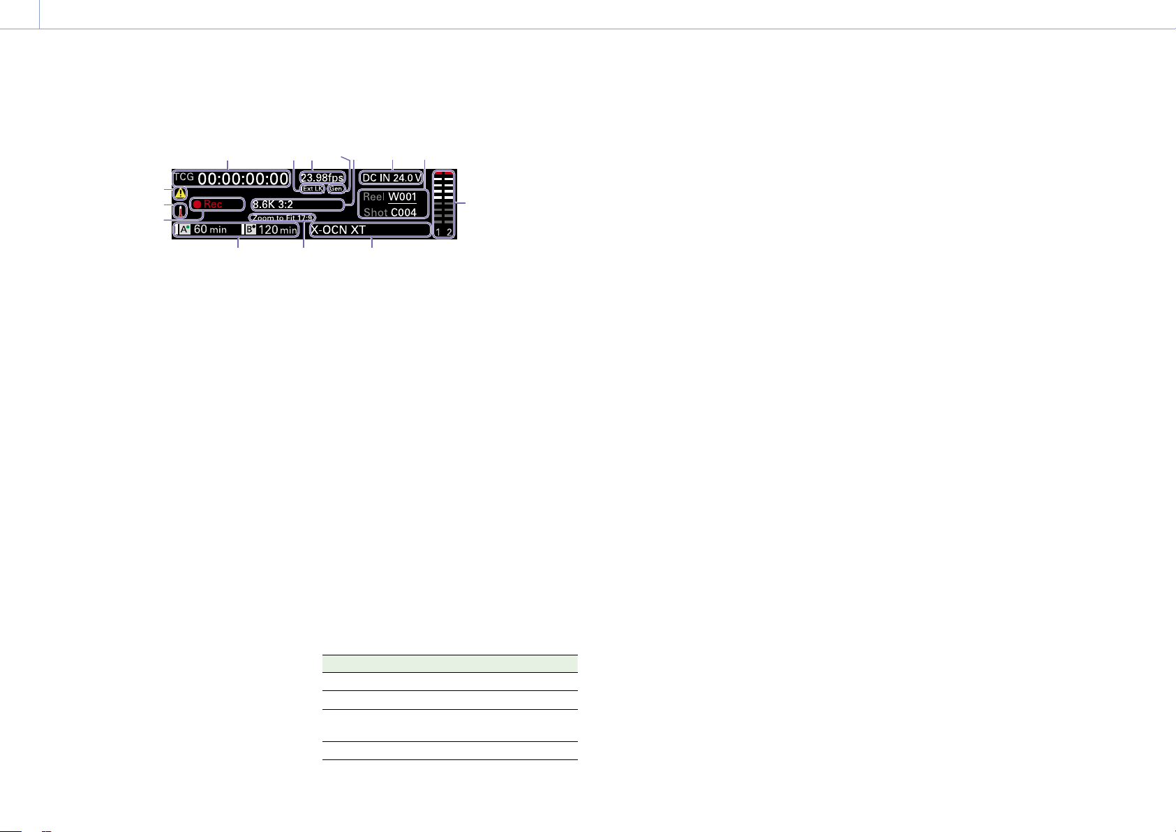
3. Camera Operations: Sub Display
37
Status display area
1 2 3 4 6 7
91011
5
8
14
13
12
1. Time data display
Displays the duration or timecode, depending
on the TC/Media category > TC Display setting
in the menu (page 56).
Displays the type of data currently shown in
the time data display, as follows.
TCG: Recorded timecode
TCR: Playback timecode
Dur: Duration
2. Ext-LK icon
Displayed when the internal timecode
generator is locked to an external signal input
to the TC IN (timecode input) connector.
3. Frame rate indicator
Displays the value of the Project category
> Project Frame Rate setting in the menu
(page 54).
4. Genlock icon
Displays locked status when genlocked.
5. Imager mode indicator
Displays the Project category > Imager
Mode setting in the menu, and de-squeeze
information.
6. Power supply voltage/Remaining battery
capacity indicator
Displays the power supply voltage or
remaining battery capacity.
7. Clip name display
Displays “Reel: Camera ID + Reel Number” and
“ShotNumber”.
8. Audio level meters
Displays the audio recording or playback
levels. The numbers 1 and 2 Indicate channels
1 and 2.
9. Recording format (codec) indicator
Displays the format of the recording on an AXS
memory card (page 59).
10. Zoom to Fit setting indicator
Displays the Project > Basic Setting > Zoom to
Fit (page 73) setting in the full menu.
[Note]
Not displayed when Zoom to Fit is set to Off or not
available.
11. Remaining media capacity indicator
Displays the active media icon, media type,
slot type (A/B), and remaining recording time
(when recording in the current recording
format).
It also displays the clip name during playback.
12. Recording status indicator
Displays the following recording operation
states of the unit.
Display Description
Stby
Recording standby
Rec
Recording
Cache
Picture cache recording
standby
CALL
CALL command incoming
13. Thermometer icon
Displayed when a high temperature warning
message is issued.
The description is displayed in the Info
category in the menu.
14. Warning icon
Displayed when other than a high temperature
warning message is issued.
The description is displayed in the Info
category in the menu.

38
3. Camera Operations
Operations on the Home Screen of the Sub Display
Basic Operation
1 Press the HOME button.
The Home screen appears.
2 Select the item to set using the ITEM keys
1 to 6.
The setting value for items that can be
changed are displayed in orange.
The following diagram shows an example
when ITEM key 3 is pressed.
3 Move the cursor to the item or setting
value to select using the
button (ITEM
key 2),
button (ITEM key 5), or MENU
dial.
4 Press the MENU dial or Set button (ITEM
key 3) to apply the setting.
Changing the brightness of the sub
display
You can change the brightness of the sub
display using Technical > Panel Control >
Brightness level (page 89) in the full menu.
On the Home screen, you can also press and
hold the BACK button and turn the MENU dial
clockwise to change the brightness of the sub
display in the sequence Minimum Low
Mid High with the current setting as the
base point.
You can also press and hold the BACK button
and turn the MENU dial counterclockwise
to change the brightness of the sub display
in the sequence High Mid Low
Minimum with the current setting as the base
point.
[Note]
The display brightness setting is common to both the
sub display and the mini display, and is reflected on
both displays simultaneously.
Display and operation when RM/RCP
Paint Control is enabled
• The gain value is displayed in the EI control
area when Technical > Special Configuration
> RM/RCP Paint Control (page 91) is set
to On in the full menu. In this mode, the EI
value cannot be changed, but the gain value
can be changed (page 39). However, the
Base ISO setting can be switched.
• The following control areas are grayed out
and cannot be operated when an RM-B170
or other remote control unit is connected
and Technical > Special Configuration > RM/
RCP Paint Control (page 91) is set to On
in the full menu. Set these using the remote
control unit (page 115).
• Shutter control area
• WB control area
• Gain control area
Step Edit Operation
You can change the settings available for
selection when “Step Edit” is displayed for
ITEM key 4 in step
2 in the basic operation. You
can add and delete settings on the settings
edit screen.
1 On the settings selection screen, move
the cursor to the setting you want to
change or delete, and press the Step Edit
button (ITEM key 4).
The settings edit screen appears.
2
To delete a setting, press the Delete button
(ITEM key 4).
[Note]
The selected setting can be deleted if the “Delete”
character string is displayed in orange.
3 Use the button (ITEM key 2), button
(ITEM key 5), or MENU dial to change the
setting.
4 When finished, press the Add button
(ITEM key 4).
The setting is added and the display
returns to the setting selection screen.
[Note]
A setting can be added if the “Add” character string
is displayed in orange.
When setting White Balance
On the White Balance settings edit screen, you
can press the Coarse/Fine button (ITEM key
1) to change the 1-step increment variation to
coarse or fine. You can also press the Temp/
Tint button (ITEM key 3) to switch the value
between color temperature (Temp) and color
tone (Tint).
FPS Operation
Press ITEM key 1 on the Home screen to
display the FPS operation screen. You can
press the Variable/Fixed button (ITEM key
4) to switch between “Fixed” for constant
speed shooting and “Variable (Select FPS)” for
variable speed shooting.
[Note]
Audio is not recorded in “Select FPS” mode.
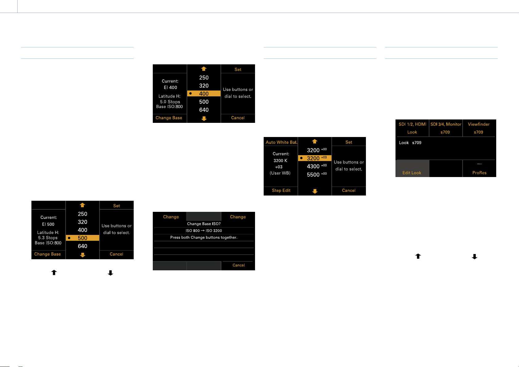
3. Camera Operations: Operations on the Home Screen of the Sub Display
39
EI Operation/Gain Operation
You can change the EI value. The gain value
is displayed instead of the EI value when
Technical > Special Configuration > RM/RCP
Paint Control (page 91) is set to On in the
full menu. You can change the gain value
when an RM-B170 or other remote control unit
is not connected.
Changing the EI value or gain value
[Note]
This section shows the display for when changing the EI
value as an example.
You can change the EI value or gain value
using ITEM key 2 on the Home screen.
1 Press ITEM key 2 on the Home screen.
The EI setup screen or Gain setup screen
appears.
2 Use the button (ITEM key 2), button
(ITEM key 5), or MENU dial to change the
setting.
3 Press the MENU dial or Set button (ITEM
key 3) to apply the setting.
Switching the Base ISO
You can switch the Base ISO by pressing ITEM
key 4 on the EI setup screen or Gain setup
screen.
1 Press ITEM key 4 on the EI setup screen or
Gain setup screen.
The Base ISO switching screen appears.
2 Press the two Change buttons (ITEM key 1
and ITEM key 3) simultaneously.
The Base ISO is changed (page 46).
AWB Operation
Press ITEM key 6 on the Home screen to
display the white balance operation screen.
Press the Auto White Bal. button (ITEM key
1) to execute white balance. After execution,
press the Add button (ITEM key 4) to add the
setting to a step. You can also press the Temp/
Tint button (ITEM key 3) to switch the value
between color temperature (Temp) and color
tone (Tint) to make fine adjustments to the
value before adding a value to a step.
[Note]
During AWB operation, shoot a white chart under
uniform lighting conditions.
LUT Operation
Setting a LUT
You can set a LUT for each output system
using ITEM key 5 on the Home screen.
1 Press ITEM key 5 on the Home screen.
The LUT selection screen appears.
[Note]
User gamma information is displayed on the LUT
selection screen when Project > Basic Setting >
Input Color Space (page 72) is set to Rec.2020/
User Gamma or Rec.709/User Gamma in the full
menu.
2 Select the output to set using ITEM keys 1,
2, 3, and 6.
The settings edit screen appears.
3 Use the button (ITEM key 2), button
(ITEM key 5), or MENU dial to change the
setting.
4 Press the MENU dial or Set button (ITEM
key 3) to apply the setting.
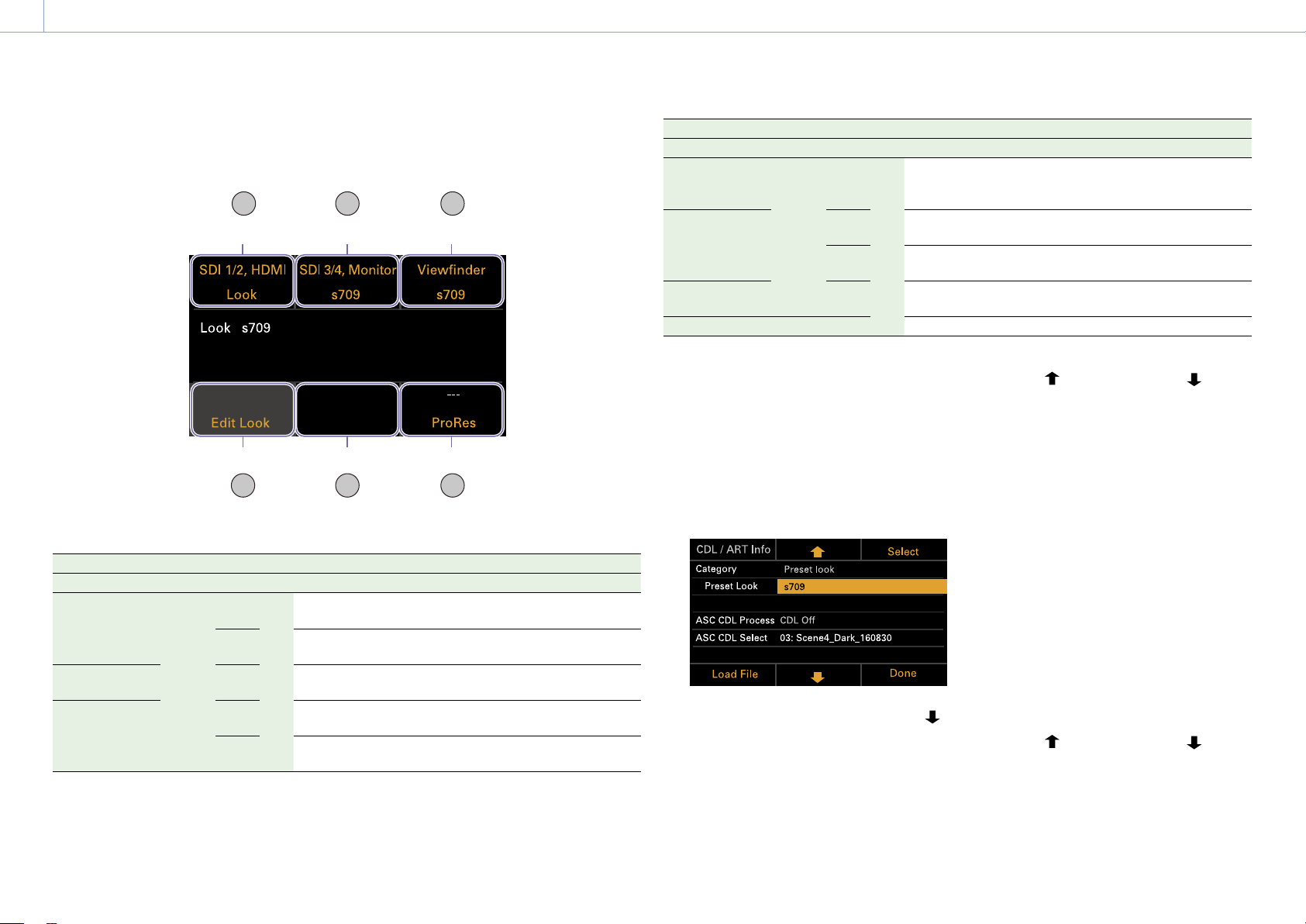
3. Camera Operations: Operations on the Home Screen of the Sub Display
40
LUT selection screen display items
The items displayed will vary depending on the Output Format setting.
1 2 3
54 6
ITEM key 5ITEM key 4 ITEM key 6
ITEM key 3ITEM key 2ITEM key 1
Output Format Display indication
SDI1/2 SDI3/4 Monitor HDMI VF ITEM key 1 ITEM key 2 ITEM key 3 ITEM key 5 ITEM key 6
4K/QFHD
12G/6G
FHD FHD 4K/
QFHD
FHD SDI 1/2,
HDMI
SDI 3/4,
Monitor
Viewfinder Blank
ProRes
1)
FHD SDI 1/2 SDI 3/4,
Moni, HDMI
Viewfinder Blank
ProRes
1)
4K/QFHD Square
Quad
FHD SDI 1/2/3/4 Blank Viewfinder Monitor,
HDMI
ProRes
1)
4K/QFHD 2SI Quad 4K/
QFHD
SDI 1-4,
HDMI
Blank Viewfinder Monitor
ProRes
1)
FHD SDI 1/2/3/4 Blank Viewfinder Monitor,
HDMI
ProRes
1)
Output Format Display indication
SDI1/2 SDI3/4 Monitor HDMI VF ITEM key 1 ITEM key 2 ITEM key 3 ITEM key 5 ITEM key 6
4K/QFHD
Square
Dual
FHD FHD FHD FHD SDI 1/2 SDI 3/4,
Moni, HDMI
Viewfinder Blank
ProRes
1)
4K/QFHD
2SI Dual
FHD 4K/
QFHD
SDI 1/2,
HDMI
SDI 3/4,
Monitor
Viewfinder Blank
ProRes
1)
FHD SDI 1/2 SDI 3/4,
Moni, HDMI
Viewfinder Blank
ProRes
1)
2K/FHD FHD FHD SDI 1/2 SDI 3/4 Viewfinder Monitor,
HDMI
ProRes
1)
FHD FHD – SD SDI 1/2 SDI 3/4 Viewfinder Monitor HDMI
1) Blank when Project > Basic Setting > Recording Format is set to X-OCN format in the full menu
Changing Preset Look
You can set a LUT when Look is selected on
the LUT selection screen using the Edit Look
button (ITEM key 4) on the LUT selection
screen.
1 Press the Edit Look button (ITEM key 4) on
the LUT selection screen.
The Look selection screen appears.
2 Select Category > Preset Look, use the
button (ITEM key 5) or MENU dial to move
the cursor to Preset Look, and press the
Select button (ITEM key 3).
The items that can be selected are
displayed.
3 Use the button (ITEM key 2), button
(ITEM key 5), or MENU dial to change the
setting.
4 Press the MENU dial or Set button (ITEM
key 3) to apply the setting.
Changing the LUT category
You can change the target category for LUT
operations to User 3D LUT, ART, ACES, or Preset
Look (page 66).
1 Press the Edit Look button (ITEM key 4) on
the LUT selection screen.
The Look selection screen appears.
2 Move the cursor to Category, and press
the MENU dial or the Select button (ITEM
key 3).
3 Use the button (ITEM key 2), button
(ITEM key 5), or MENU dial to select a
category (User 3D LUT, ART, ACES, or
Preset Look).
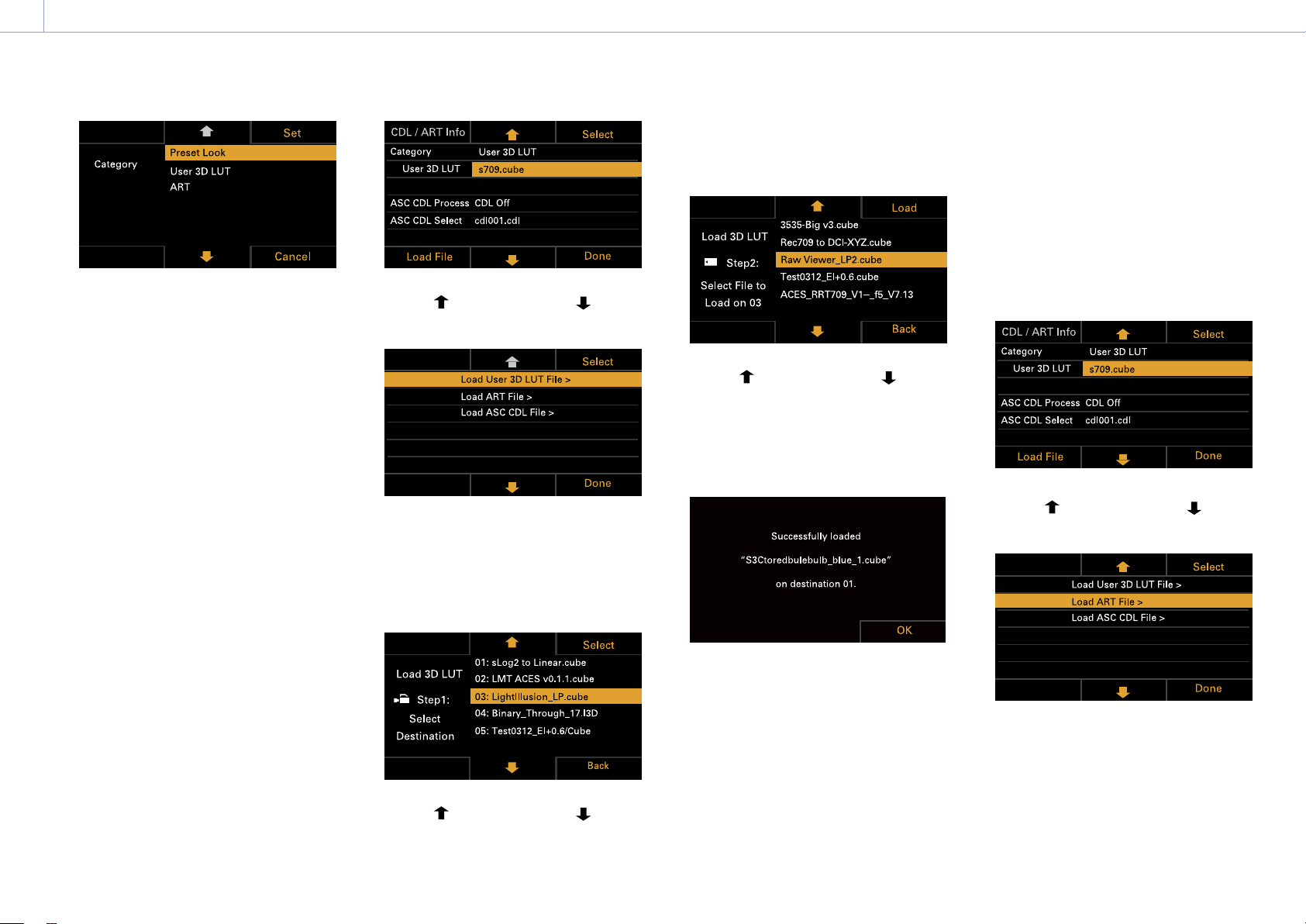
3. Camera Operations: Operations on the Home Screen of the Sub Display
41
[Note]
The selection options change as follows depending
on the Project > Basic Setting > Input Color Space
(page 72) setting in the full menu.
– S-Gamut3.Cine/SLog3 or S-Gamut3/SLog3:
Preset Look / User 3D LUT / ART
– ACEScct: Preset Look / ACEScct with User 3D /
ACESproxy with User 3D / ACES with ART
4 Press the MENU dial or Set button (ITEM
key 3) to apply the setting.
Loading a User 3D LUT file
You can load a User 3D LUT file stored on an
SD card into the unit.
You can also load a User 3D LUT file into the
unit via a network (page 104).
[Note]
Save the User 3D LUT file in the following directory on
the SD card (page 110).
PRIVATE\SONY\PRO\LUT\
1 Insert the SD card into the SD card slot
(page 13).
2 Press the Edit Look button (ITEM key 4) on
the LUT selection screen.
The Look selection screen appears.
3 Press the Load File button (ITEM key 4).
A file type selection screen appears.
4 Use the button (ITEM key 2), button
(ITEM key 5), or MENU dial to select Load
User 3D LUT File.
5 Press the MENU dial or the Select button
(ITEM key 3).
The load destination numbers (01 to 16)
are displayed.
A file name is displayed for loaded
numbers.
6 Use the button (ITEM key 2), button
(ITEM key 5), or MENU dial to select a load
destination number.
7 Press the MENU dial or the Select button
(ITEM key 3).
The file name of the User 3D LUT file
stored on the SD card is displayed.
8 Use the button (ITEM key 2), button
(ITEM key 5), or MENU dial to select a file.
9 Press the MENU dial or the Load button
(ITEM key 3).
When the file is loaded successfully,
“Successfully loaded” is displayed.
10 Press the OK button (ITEM key 6).
Loading an ART file
You can load an ART file stored on an SD card
into the unit.
You can also load an ART file into the unit via a
network (page 105).
[Note]
Save the ART file in the following directory on the SD
card (page 110).
MPC-3628:
PRIVATE\SONY\PRO\CAMERA\MPC3628
MPC-3626:
PRIVATE\SONY\PRO\CAMERA\MPC3626
1 Insert the SD card into the SD card slot
(page 13).
2 Press the Edit Look button (ITEM key 4) on
the LUT selection screen.
The Look selection screen appears.
3 Press the Load File button (ITEM key 4).
A file type selection screen appears.
4 Use the button (ITEM key 2), button
(ITEM key 5), or MENU dial to select Load
ART File.
5 Press the MENU dial or the Select button
(ITEM key 3).
The load destination numbers (01 to 16)
are displayed.
A file name is displayed for loaded
numbers.

3. Camera Operations: Operations on the Home Screen of the Sub Display
42
6 Use the button (ITEM key 2), button
(ITEM key 5), or MENU dial to select a load
destination number.
7 Press the MENU dial or the Select button
(ITEM key 3).
The file name of the ART file stored on
the SD card is displayed.
8 Use the button (ITEM key 2), button
(ITEM key 5), or MENU dial to select a file.
9 Press the MENU dial or the Load button
(ITEM key 3).
When the file is loaded successfully,
“Successfully loaded” is displayed.
10 Press the OK button (ITEM key 6).
Loading an ASC CDL file
You can load an ASC CDL file stored on an SD
card into the unit.
You can also load an ASC CDL file into the unit
via a network (page 105).
[Note]
Save the ASC CDL file in the following directory on the
SD card (page 110).
PRIVATE\SONY\PRO\CDL\
1 Insert the SD card into the SD card slot
(page 13).
2 Press the Edit Look button (ITEM key 4) on
the LUT selection screen.
The Look selection screen appears.
3 Press the Load File button (ITEM key 4).
A file type selection screen appears.
4 Select Load ASC CDL File, and press the
MENU dial or the Select button (ITEM key
3).
The file name of the ASC CDL file stored
on the SD card is displayed.
5 Use the button (ITEM key 2), button
(ITEM key 5), or MENU dial to select a file.
6 Press the MENU dial or the Load button
(ITEM key 3).
You can press the Load All Files button
(ITEM key 1) to load all files.
When the file is loaded successfully,
“Successfully loaded” is displayed.
7 Press the OK button (ITEM key 6).
Changing the User 3D LUT File
You can change the currently selected User 3D
LUT file.
1 Press the Edit Look button (ITEM key 4) on
the LUT selection screen.
The Look selection screen appears.
2 Move the cursor to Category, and press
the MENU dial or the Select button (ITEM
key 3) to select User 3D LUT.
3 Move the cursor to User 3D LUT, and
press the MENU dial or the Select button
(ITEM key 3).
4 Use the button (ITEM key 2), button
(ITEM key 5), or MENU dial to change the
User 3D LUT file.

3. Camera Operations: Operations on the Home Screen of the Sub Display
43
5 Press the MENU dial or Set button (ITEM
key 3) to apply the setting.
Changing the ART File
You can change the currently selected ART file.
1 Press the Edit Look button (ITEM key 4) on
the LUT selection screen.
The Look selection screen appears.
2 Move the cursor to Category, and press
the MENU dial or the Select button (ITEM
key 3) to select ART.
3 Move the cursor to ART, and press the
MENU dial or the Select button (ITEM key
3).
4 Use the button (ITEM key 2), button
(ITEM key 5), or MENU dial to change the
ART file.
5 Press the MENU dial or Set button (ITEM
key 3) to apply the setting.
Displaying ART file information
You can display information for the currently
selected ART file.
1 Press the Edit Look button (ITEM key 4) on
the LUT selection screen.
The Look selection screen appears.
2 Move the cursor to ART, and press the
CDL / ART Info button (ITEM key 1).
The ART file information is displayed.
Changing the ASC CDL File
You can change the currently selected ASC
CDL file.
1 Press the Edit Look button (ITEM key 4) on
the LUT selection screen.
The Look selection screen appears.
2 Select ASC CDL Select, and press the
MENU dial or the Select button (ITEM key
3).
3 Use the button (ITEM key 2), button
(ITEM key 5), or MENU dial to change the
ASC CDL file.
[Note]
Files that cannot be applied on the unit are grayed
out.
4 Press the MENU dial or Set button (ITEM
key 3) to apply the setting.
Specifying the ASC CDL file processing
order
You can specify the ASC CDL processing order
using ASC CDL Process on the Look selection
screen.
Displaying ASC CDL file information
You can display information for the currently
selected ASC CDL file.
1 Press the Edit Look button (ITEM key 4) on
the LUT selection screen.
The Look selection screen appears.
2 Move the cursor to ASC CDL Select, and
press the CDL / ART Info button (ITEM key
1).
The ASC CDL file information screen
appears.
You can change the Saturation setting on
the ASC CDL file information screen.

3. Camera Operations: Operations on the Home Screen of the Sub Display
44
Changing Saturation
1 Press the Edit button (ITEM key 4) on the
ASC CDL file information screen.
The Saturation edit screen appears.
2 Move the cursor to the digit to change
using the MENU dial, and press the MENU
dial.
3 Use the MENU dial to change the setting,
and press the MENU dial.
The Saturation setting range is 0.000 to
3.999.
[Note]
If you enter a value that exceeds the setting range
and press the MENU dial, the previous value is
restored.
4 Move the cursor to the Set button using
the MENU dial, and press the MENU dial to
apply the setting.
About the ASC CDL file setting ranges
The ASC CDL file setting ranges are shown
below. Files that exceed the ranges cannot be
loaded.
Slope: 0.000 to 3.999
Offset: –1.000 to 1.000
Power: 0.400 to 4.000
Saturation: 0.000 to 3.999
Home Screen Items on the Sub Display
The names of items and corresponding setting values are given below.
Default values are shown underlined and in
bold text.
Item Description
FPS Sets the shooting frame rate.
Variable/Fixed: Switch between variable speed and constant speed
shooting.
When “Fixed” is selected, the setting is determined by the Project category
> Project Frame Rate (page 54) setting in the menu.
Project Frame Rate Display
23.98 Fix 23.98
24 Fix 24.00
25 Fix 25.00
29.97 Fix 29.97
47.95 Fix 47.95
50 Fix 50.00
59.94 Fix 59.94
3. Camera Operations: Operations on the Home Screen of the Sub Display
45
Item Description
When “Variable” is selected, the settings change as follows depending on
the Project category > Imager Mode (page 72) and Recording Format
(page 72) settings in the menu.
X-OCN recording
MPC-3628
Imager Mode Shooting frame rate
8.6K 3:2 1 to 30FPS
8.2K 17:9
7.6K 16:9
1 to 60FPS
5.8K 6:5 1 to 48FPS
5.8K 17:9
5.4K 16:9
1 to 60, 66, 72, 75, 88, 90FPS
MPC-3626
Imager Mode Shooting frame rate
6K 3:2 1 to 60FPS
6K 1.85:1
6K 17:9
5.7K 16:9
1 to 60, 66, 72FPS
6K 2.39:1 1 to 60, 66, 72, 75, 88, 90FPS
4K 6:5 1 to 60, 66, 72FPS
4K 4:3 1 to 60, 66, 72, 75FPS
4K 4:3 Surround View 1 to 30FPS
4K 17:9
3.8K 16:9
1 to 60, 66, 72, 75, 88, 90, 96, 100,
110FPS
4K 17:9 Surround View
3.8K 16:9 Surround View
1 to 48FPS
4K 2.39:1 1 to 60, 66, 72, 75, 88, 90, 96, 100,
110, 120FPS
Item Description
ProRes recording
MPC-3628
Imager Mode Shooting frame rate
ProRes 4K / QFHD
4444 422 HQ
8.2K 17:9
7.6K 16:9
1 to 60FPS 1 to 60FPS
5.8K 6:5 1 to 48FPS 1 to 48FPS
5.8K 17:9
5.4K 16:9
1 to 60FPS 1 to 60, 66, 72, 75FPS
MPC-3626
Imager Mode Shooting frame rate
ProRes 4K / QFHD
4444 422 HQ
6K 17:9
5.7K 16:9
1 to 60FPS 1 to 60, 66, 72FPS
6K 2.39:1 1 to 60FPS 1 to 60, 66, 72, 75FPS
4K 6:5 1 to 60FPS 1 to 60, 66, 72FPS
4K 17:9
3.8K 16:9
1 to 60FPS 1 to 60, 66, 72, 75, 88,
90FPS
4K 17:9 Surround View
3.8K 16:9 Surround View
1 to 48FPS 1 to 48FPS
4K 2.39:1 1 to 60FPS 1 to 60, 66, 72, 75, 88,
90FPS
[Note]
Shooting frame rates of 7 or lower cannot be set in the following cases.
– When Base ISO is set to ISO 3200
– When Base ISO is set to ISO 2500 and the recording format is ProRes

3. Camera Operations: Operations on the Home Screen of the Sub Display
46
Item Description
Exposure Index
Sets the EI value. You can change the Base ISO setting by pressing the
Change Base button (ITEM key 4) and then simultaneously pressing the two
Change buttons (ITEM key 1 and ITEM key 3) on the subsequent screen. The
available settings vary as follows depending on the Base ISO setting.
MPC-3628
Base ISO 800:
200EI/250EI/320EI/400EI/500EI/640EI/
800EI/1000EI/1250EI/
1600EI/2000EI/2500EI/3200EI
Base ISO 3200:
800EI/1000EI/1250EI/1600EI/2000EI/2500EI/
3200EI/4000EI/
5000EI/6400EI/8000EI/10000EI/12800EI
MPC-3626
Base ISO 500:
125EI/160EI/200EI/250EI/320EI/400EI/500EI/640EI/800EI/1000EI/
1250EI/1600EI/2000EI
Base ISO 2500:
640EI/800EI/1000EI/1250EI/1600EI/2000EI/
2500EI/3200EI/4000EI/
5000EI/6400EI/8000EI/10000EI
Gain
Sets the base sensitivity.
–6dB/–3dB/
0dB/3dB/6dB/9dB/12dB/15dB/18dB
[Note]
Configurable only when an RM-B170 or other remote control unit is connected and
Technical > Special Configuration > RM/RCP Paint Control (page 91) is set to On in
the full menu.
Shutter Sets the electronic shutter angle/shutter speed.
Press the Step/Cont. button (ITEM key 1) to switch between step and
continuous selection methods.
Step: Select from up to 16 preset values registered as shutter steps. You can
press the Step Edit button (ITEM key 4) to change any setting from the
preset value after selection.
Displays the following selection options depending on the Technical >
System Configuration > Shutter Mode (page 87) setting in the full
menu.
Angle: Shutter angle indicator
Default selection options
360/180/172.8/144/90/45/22.5/11.2/5.6
Speed: Shutter speed indicator
Default selection options
1/24, 1/25, 1/30, 1/50, 1/60, 1/100, 1/120, 1/250, 1/500, 1/1000, 1/2000
1)
[Note]
The default speed values for different Project Frame Rate (page 54) settings
are given below.
23.98/24: 1/24, 25: 1/25, 29.97: 1/30, 47.95: 1/48, 50: 1/50, 59.94: 1/60
Cont.: Select an angle/speed within the supported range.
Item Description
ND Filter
Sets the ND filter position. The following settings are available.
Clear/0.3/0.6/0.9/1.2/1.5/1.8/2.1/2.4
LUT
Configures settings related to the LUT to apply to the output video. The
settings will vary depending on the Technical > Special Configuration > RM/
RCP Paint Control (page 91) setting in the full menu.
SDI 1/2
When RM/RCP Paint Control is set to Off: Log/
Look
Selects the LUT to apply to the SDI 1/2 output image.
When RM/RCP Paint Control is set to On:
Log/HLG(Natural)/HLG(Live)/
User Gamma
The SDI 1/2 output image setting is display only, because it is
determined by the Project category > Input Color Space setting in the
menu.
SDI 3/4
When RM/RCP Paint Control is set to Off: Log/
Look
Selects the LUT to apply to the SDI 3/4 output image.
When RM/RCP Paint Control is set to On:
Log/HLG(Natural)/HLG(Live)/
User Gamma
The SDI 3/4 output image setting is display only, because it is
determined by the Project category > Input Color Space setting in the
menu.
Monitor
When RM/RCP Paint Control is set to Off:
Selects the LUT to apply to the Monitor output image.
The settings change as follows depending on the Project category >
Input Color Space setting in the menu.
S-Gamut3.Cine/SLog3 or S-Gamut3/SLog3: Log/
s709/R709(800%)/
Look
ACEScct: Log/s709/R709(800%)/
Look
When RM/RCP Paint Control is set to On:
Selects the type of Monitor output image.
The settings change as follows depending on the Project category >
Input Color Space setting in the menu.
S-Gamut3.Cine/SLog3 or S-Gamut3/SLog3:
Log/R709(800%)
HLG(Natural):
HLG(Natural)/R709(800%)
HLG(Live):
HLG(Live)/R709(800%)
Rec.2020/User Gamma:
User Gamma/R709-Like
Rec.709/User Gamma: User Gamma

3. Camera Operations: Operations on the Home Screen of the Sub Display
47
Item Description
Viewfinder
When RM/RCP Paint Control is set to Off:
Selects the LUT to apply to the viewfinder/monitor screen output
image.
The settings change as follows depending on the Project category >
Input Color Space setting in the menu.
S-Gamut3.Cine/SLog3 or S-Gamut3/SLog3: Log/
s709/R709(800%)/
Look
ACEScct: Log/s709/R709(800%)/
Look
When RM/RCP Paint Control is set to On:
Selects the type of viewfinder/monitor screen output image.
The settings change as follows depending on the Project category >
Input Color Space setting in the menu.
S-Gamut3.Cine/SLog3 or S-Gamut3/SLog3: Log/R709(800%)
HLG(Natural): HLG(Natural)
HLG(Live): HLG(Live)
Rec.2020/User Gamma: User Gamma/
R709-Like
Rec.709/User Gamma: User Gamma
ProRes(Recording)
When RM/RCP Paint Control is set to Off: Log/
Look
Selects the LUT to apply to the ProRes recording image.
When RM/RCP Paint Control is set to On:
Log/HLG(Natural)/HLG(Live)/
User Gamma
The ProRes recording image setting is display only, because it is
determined by the Project category > Input Color Space setting in
the menu.
[Note]
Displayed and configurable when Project > Basic Setting > Recording Format
(page 72) is set to ProRes format in the full menu.
Edit Look
Sets a LUT to apply as a Look.
s709 / R709(800%) / S-Gamut3.Cine/SLog3 / S-Gamut3/SLog3 / User
3D LUT
WB (White Balance)
Sets the color temperature/color tone of the white balance.
Default selection options
3200K+00/4300K+00/5500K+00
You can press the Step Edit button (ITEM key 4) to change the white
balance preset value and Tint value.
Auto White Bal.: Execute auto white balance.
1) The options are 1/60 and subsequent values when the project frame rate is 59.94, 1/50 and subsequent values
when 50.0, 1/30 and subsequent values when 29.97, and 1/25 and subsequent values when 25.0.

48
3. Camera Operations
User Functions Screen
You can press the USER button (page 11)
to display the user functions screen on the
sub display and use the ITEM keys 1 to 5 as
assignable buttons (User 1 to 5).
There are also four assignable buttons (1 to
4) (pages 9, 10, 11) on the unit and
three assignable buttons (VF A to VF C) on
the viewfinder (DVF-EL200) to which you can
assign various functions.
Functions can be assigned to these buttons
using the user functions screen, in addition to
using Project > Assignable Button in the full
menu.
ITEM key 4 ITEM key 5 ITEM key 6
ITEM key 3ITEM key 2ITEM key 1
[Note]
When a lens that supports the iris setting display
function is attached, the iris position is displayed in the
center left of the user functions screen.
Changing Button Functions
The user functions selection screen is
displayed by pressing the Edit button (ITEM
key 6) on the user functions screen. You can
set the functions for the User 1 to 5 buttons,
assignable buttons 1 to 4, and viewfinder
assignable buttons A to C on the user
functions selection screen.
1 On the user functions selection screen,
move the cursor to the button you want
to change, and press the Select button
(ITEM key 3).
The functions that can be selected are
displayed.
2 Use the button (ITEM key 2), button
(ITEM key 5), or MENU dial to change the
setting.
3
When finished, press the Set button (ITEM
key 3).
The display returns to the user functions
screen, and displays the changed function.
The following table lists the functions that are assigned when the unit is shipped from the
factory.
Button Function Assignable Button setting
Assignable 1 Displays clipped highlight areas in red in the
viewfinder.
VF Highlight Clip Ind
Assignable 2 No assignment Not Assigned
Assignable 3 No assignment Not Assigned
Assignable 4 No assignment Not Assigned
ITEM key 1 No assignment Not Assigned
ITEM key 2 No assignment Not Assigned
ITEM key 3 No assignment Not Assigned
ITEM key 4 Displays clipped highlight areas in red on the
Monitor output.
Monitor Highlight Clip Ind
ITEM key 5 Sets the fan control mode. Fan Mode
Viewfinder
assignable A
Turns the focus magnifier function of the
viewfinder on/off.
VF Focus Magnifier
Viewfinder
assignable B
Turns the false color function display in a
viewfinder on/off.
VF False Color
Viewfinder
assignable C
Turns the information display on the
viewfinder/monitor screen output image on/
off.
VF Overlay
Functions that can be Assigned to ITEM Keys 1 to 5
Assignable Button
setting
Function State after rebooting
No Assign No assignment –
Fan Mode Sets the fan control mode.
Switches between Auto Max Off in Rec/
Auto Off in Rec/Max each time the key is
pressed.
Setting retained
Auto Pixel
Restoration
Executes auto pixel restoration. –
PL-Mt Interface
Position
Sets the interface position of the PL-mount
lens.
Switches between Top Side Off each
time the key is pressed.
Setting retained
3. Camera Operations: User Functions Screen
49
Assignable Button
setting
Function State after rebooting
SDI 1/2 Frame Line Turns superimposition of frame lines on the
SDI 1/2 output image on/off.
Setting retained
SDI 3/4 Frame Line Turns superimposition of frame lines on the
SDI 3/4 output image on/off.
Setting retained
SDI Overlay Turns display of information on the SDI output
image on/off.
Setting retained
Press&Hold for SDI12
Log
Disables the LUT applied to the SDI 1/2 output
image while the button is pressed, and sets
Log image quality without applying a LUT.
Setting not retained
Press&Hold for SDI34
Log
Disables the LUT applied to the SDI 3/4 output
image while the button is pressed, and sets
Log image quality without applying a LUT.
When the SDI 3/4 output and Monitor output
are linked, Press & Hold for Moni Log is also
enabled.
Setting not retained
Monitor Frame Line Turns superimposition of frame lines on the
Monitor output image on/off.
Setting retained
Monitor Overlay Turns display of information on the Monitor
output image on/off.
Setting retained
Press & Hold for Moni
Log
4)
Disables the LUT applied to the Monitor
output image while the key is pressed for
normal image quality without applying a LUT.
When the SDI 3/4 output and Monitor output
are linked, Press&Hold for SDI34 Log is also
enabled.
When the HDMI output and Monitor output
are linked, HDMI output is also enabled.
Setting not retained
Monitor Focus
Magnifier
2) 3)
Turns the focus magnifier function of the
Monitor output image on/off.
Setting not retained
Monitor Highlight
Clip Ind
1)
Turns the function that displays clipped
highlight areas in red on the Monitor output
image on/off.
Setting retained
Monitor False Color
1)
Turns the false color function display on a
monitor on/off.
Setting retained
Line A: Aspect Ratio
Disp.
Turns the Aspect Ratio display for Line A on/
off.
Setting retained
Line B: Aspect Ratio
Disp.
Turns the Aspect Ratio display for Line B on/
off.
Setting retained
Assignable Button
setting
Function State after rebooting
Line A: User Frame
Disp.
Turns the User Frame Line 1 and User Frame
Line 2 display for Line A on/off.
Each time the key is pressed, the display
switches between User Frame Line 1 and 2
display User Frame Line 1 display User
Frame Line 2 display User Frame Line 1 and
2 hidden.
Setting retained
Line B: User Frame
Disp.
Turns the User Frame Line 1 and User Frame
Line 2 display for Line B on/off.
Each time the key is pressed, the display
switches between User Frame Line 1 and 2
display User Frame Line 1 display User
Frame Line 2 display User Frame Line 1 and
2 hidden.
Setting retained
H & V Flip
7)
Flips the shooting mode image orientation. Setting retained
Anamorphic De-
Squeeze
Changes the Project > Basic Setting > Anamo.
De-Squeeze setting in the full menu.
Each time the key is pressed, the setting
changes to the next item in the list of menu
selection options.
Setting retained
Auto White Balance
5)
Executes auto white balance. –
Color Bars
5)
Turns color bars on/off. Setting retained
Picture Cache Rec Turns the picture cache recording function
on/off.
Setting retained
AXS Slot Change Switches the active slot when two AXS
memory cards are inserted.
Switches between A and B each time the key
is pressed.
Setting retained
Format Media AXS
Slot A
Formats media in AXS slot A. –
Format Media AXS
Slot B
Formats media in AXS slot B. –
Iris Open (1/16 stop)
6)
Opens the lens iris.
Press and hold to open the iris until fully
open.
This function is available when an E-mount
lens with power iris is attached.
The setting is in 1/16 stop increments,
whereas the iris indication is in units of 1/3
stop increments.
–
3. Camera Operations: User Functions Screen
50
Assignable Button
setting
Function State after rebooting
Iris Close (1/16 stop)
6)
Closes the lens iris.
Press and hold to close the iris until fully
closed.
This function is available when an E-mount
lens with power iris is attached.
The setting is in 1/16 stop increments,
whereas the iris indication is in units of 1/3
stop increments.
–
1) Does not function if the key is pressed when Technical > Special Configuration > RM/RCP Paint Control (page 91)
is set to On in the full menu.
2) Also applied to the HDMI output if the HDMI output has the same output format as the Monitor output. You can
check the setting using Monitoring > Overlays/Frame Line > HDMI (page 79) in the full menu. The HDMI output is
the same as the Monitor output if HDMI is set to “Same as Monitor”.
3) If the SDI output format is 1920×1080i, the focus magnifier function is off, and pressing the button performs no
function.
4) Switches to the same image as the main signal that is selected using Project > Basic Setting > Input Color Space
(page 72) in the full menu while the button is pressed.
5) Does not function if the key is pressed when an RM-B170 or other remote control unit is connected and Technical >
Special Configuration > RM/RCP Paint Control (page 91) is set to On in the full menu.
6) Does not function if the key is pressed when an RM-B170 or other remote control unit is connected.
7) Does not function if the key is pressed when Monitoring > Output Display > Flip Image (page 77) > H & V Flip in
the full menu is grayed out.
Functions that can be Assigned to Assignable Buttons 1 to 4
Assignable Button
setting
Function State after rebooting
No Assign No assignment –
SDI 1/2 Frame Line Turns superimposition of frame lines on the
SDI 1/2 output image on/off.
Setting retained
SDI 3/4 Frame Line Turns superimposition of frame lines on the
SDI 3/4 output image on/off.
Setting retained
SDI Overlay Turns display of information on the SDI output
image on/off.
Setting retained
Press&Hold for SDI12
Log
Disables the LUT applied to the SDI 1/2 output
image while the button is pressed, and sets
Log image quality without applying a LUT.
Setting not retained
Press&Hold for SDI34
Log
Disables the LUT applied to the SDI 3/4 output
image while the button is pressed, and sets
Log image quality without applying a LUT.
When the SDI 3/4 output and Monitor output
are linked, Press & Hold for Moni Log is also
enabled.
Setting not retained
Monitor Frame Line Turns superimposition of frame lines on the
Monitor output image on/off.
Setting retained
Monitor Overlay Turns display of information on the Monitor
output image on/off.
Setting retained
Press & Hold for Moni
Log
4)
Disables the LUT applied to the Monitor
output image while the key is pressed for
normal image quality without applying a LUT.
When the SDI 3/4 output and Monitor output
are linked, Press&Hold for SDI34 Log is also
enabled.
When the HDMI output and Monitor output
are linked, HDMI output is also enabled.
Setting not retained
Monitor Focus
Magnifier
2) 3)
Turns the focus magnifier function of the
Monitor output image on/off.
Setting not retained
Monitor Highlight
Clip Ind
1)
Turns the function that displays clipped
highlight areas in red on the Monitor output
image on/off.
Setting retained
3. Camera Operations: User Functions Screen
51
Assignable Button
setting
Function State after rebooting
Monitor High/Low
Key
1)
Selects the Monitor output mode.
Switches between High Key (screen for
checking for blown-out highlights) Low
Key (screen for checking for blocked-out
shadows) Off (normal display) each time
the button is pressed.
Setting not retained
Monitor False Color
1)
Turns the false color function display on a
monitor on/off.
Setting retained
VF Frame Line Turns superimposition of frame lines on the
viewfinder/monitor screen output image on/
off.
Setting retained
VF Overlay Turns the information display on the
viewfinder/monitor screen output image on/
off.
Setting retained
Press & Hold for VF
Log
6)
Disables the LUT applied to the viewfinder/
monitor screen output image while the
button is pressed for normal image quality
without applying a LUT.
Setting not retained
VF Focus Magnifier Turns the focus magnifier function of the
viewfinder on/off.
Setting not retained
VF Highlight Clip Ind
1)
Turns the function to display clipped highlight
areas in red in the viewfinder on/off.
Setting retained
VF High/Low Key
1)
Selects the viewfinder output mode.
Switches between High Key (screen for
checking for blown-out highlights) Low
Key (screen for checking for blocked-out
shadows) Off (normal display) each time
the button is pressed.
Setting not retained
VF False Color
1)
Turns the false color function display in a
viewfinder on/off.
Setting retained
VF Zebra Turns the zebra function of the viewfinder/
monitor screen output image on/off.
Setting retained
Line A: Aspect Ratio
Disp.
Turns the Aspect Ratio display for Line A on/
off.
Setting retained
Line B: Aspect Ratio
Disp.
Turns the Aspect Ratio display for Line B on/
off.
Setting retained
Assignable Button
setting
Function State after rebooting
Line A: User Frame
Disp.
Turns the User Frame Line 1 and User Frame
Line 2 display for Line A on/off.
Each time the button is pressed, the display
switches between User Frame Line 1 and 2
display User Frame Line 1 display User
Frame Line 2 display User Frame Line 1 and
2 hidden.
Setting retained
Line B: User Frame
Disp.
Turns the User Frame Line 1 and User Frame
Line 2 display for Line B on/off.
Each time the button is pressed, the display
switches between User Frame Line 1 and 2
display User Frame Line 1 display User
Frame Line 2 display User Frame Line 1 and
2 hidden.
Setting retained
H & V Flip
8)
Flips the shooting mode image orientation. Setting retained
Anamorphic De-
Squeeze
Changes the Project > Basic Setting > Anamo.
De-Squeeze setting in the full menu.
Each time the button is pressed, the setting
changes to the next item in the list of menu
selection options.
Setting retained
Auto White Balance
5)
Executes auto white balance. –
Color Bars
5)
Turns color bars on/off. Setting retained
Rec Starts/stops recording. –
Rec Review Executes the Rec Review function. Setting not retained
Picture Cache Rec Turns the picture cache recording function
on/off.
Setting retained
AXS Slot Change Switches the active slot when two AXS
memory cards are inserted.
Switches between A and B each time the
button is pressed.
Setting retained
ND +1stop Switches the ND filter one stop in the darker
direction.
–
ND -1stop Switches the ND filter one stop in the brighter
direction.
–
3. Camera Operations: User Functions Screen
52
Assignable Button
setting
Function State after rebooting
Iris Open (1/16 stop)
7)
Opens the lens iris.
Press and hold to open the iris until fully
open.
This function is available when an E-mount
lens with power iris is attached.
The setting is in 1/16 stop increments,
whereas the iris indication is in units of 1/3
stop increments.
–
Iris Close (1/16 stop)
7)
Closes the lens iris.
Press and hold to close the iris until fully
closed.
This function is available when an E-mount
lens with power iris is attached.
The setting is in 1/16 stop increments,
whereas the iris indication is in units of 1/3
stop increments.
–
1) Does not function if the button is pressed when Technical > Special Configuration > RM/RCP Paint Control
(page 91) is set to On in the full menu.
2) Also applied to the HDMI output if the HDMI output has the same output format as the Monitor output. You can
check the setting using Monitoring > Overlays/Frame Line > HDMI (page 79) in the full menu. The HDMI output is
the same as the Monitor output if HDMI is set to “Same as Monitor”.
3) If the SDI output format is 1920×1080i, the focus magnifier function is off, and pressing the button performs no
function.
4) Switches to the same image as the main signal that is selected using Project > Basic Setting > Input Color Space
(page 72) in the full menu while the button is pressed.
5) Does not function if the button is pressed when an RM-B170 or other remote control unit is connected and
Technical > Special Configuration > RM/RCP Paint Control (page 91) is set to On in the full menu.
6) When Technical > Special Configuration > RM/RCP Paint Control (page 91) is set to On and Shooting > LUT Select
> VF LUT (page 70) is set to R709(800%) or R709-Like in the full menu, this switches to the same image as the
main signal while the button is pressed. When RM/RCP Paint Control is set to Off and VF LUT is not set to Log, this
switches to the same image as the main signal while the button is pressed.
7) Does not function if the button is pressed when an RM-B170 or other remote control unit is connected.
8) Does not function if the button is pressed when Monitoring > Output Display > Flip Image (page 77) > H & V Flip
in the full menu is grayed out.
Functions that can be Assigned to Viewfinder (DVF-EL200) Assignable
Buttons A to C
Assignable Button
setting
Function State after rebooting
No Assign No assignment –
VF Frame Line Turns superimposition of frame lines on the
viewfinder/monitor screen output image on/
off.
Setting retained
VF Overlay Turns the information display on the
viewfinder/monitor screen output image on/
off.
Setting retained
Press & Hold for VF
Log
2)
Disables the LUT applied to the viewfinder/
monitor screen output image while the
button is pressed for normal image quality
without applying a LUT.
Setting not retained
VF Focus Magnifier Turns the focus magnifier function of the
viewfinder on/off.
Setting not retained
VF Highlight Clip Ind
3)
Turns the function to display clipped highlight
areas in red in the viewfinder on/off.
Setting retained
VF High/Low Key
3)
Selects the viewfinder output mode.
Switches between High Key (screen for
checking for blown-out highlights) Low
Key (screen for checking for blocked-out
shadows) Off (normal display) each time
the button is pressed.
Setting not retained
VF False Color
3)
Turns the false color function display in a
viewfinder on/off.
Setting retained
VF Zebra Turns the zebra function of the viewfinder/
monitor screen output image on/off.
Setting retained
Line A: Aspect Ratio
Disp.
Turns the Aspect Ratio display for Line A on/
off.
Setting retained
Line B: Aspect Ratio
Disp.
Turns the Aspect Ratio display for Line B on/
off.
Setting retained
Line A: User Frame
Disp.
Turns the User Frame Line 1 and User Frame
Line 2 display for Line A on/off.
Each time the button is pressed, the display
switches between User Frame Line 1 and 2
display User Frame Line 1 display User
Frame Line 2 display User Frame Line 1 and
2 hidden.
Setting retained
3. Camera Operations: User Functions Screen
53
Assignable Button
setting
Function State after rebooting
Line B: User Frame
Disp.
Turns the User Frame Line 1 and User Frame
Line 2 display for Line B on/off.
Each time the button is pressed, the display
switches between User Frame Line 1 and 2
display User Frame Line 1 display User
Frame Line 2 display User Frame Line 1 and
2 hidden.
Setting retained
H & V Flip
5)
Flips the shooting mode image orientation. Setting retained
Anamorphic De-
Squeeze
Changes the Project > Basic Setting > Anamo.
De-Squeeze setting in the full menu.
Each time the button is pressed, the setting
changes to the next item in the list of menu
selection options.
Setting retained
Color Bars
1)
Turns color bars on/off. Setting retained
Rec Starts/stops recording. –
Rec Review Executes the Rec Review function. Setting not retained
Picture Cache Rec Turns the picture cache recording function
on/off.
Setting retained
AXS Slot Change Switches the active slot when two AXS
memory cards are inserted.
Switches between A and B each time the
button is pressed.
Setting retained
ND +1stop Switches the ND filter one stop in the darker
direction.
–
ND -1stop Switches the ND filter one stop in the brighter
direction.
–
Iris Open (1/16 stop)
4)
Opens the lens iris.
Press and hold to open the iris until fully
open.
This function is available when an E-mount
lens with power iris is attached.
The setting is in 1/16 stop increments,
whereas the iris indication is in units of 1/3
stop increments.
–
Assignable Button
setting
Function State after rebooting
Iris Close (1/16 stop)
4)
Closes the lens iris.
Press and hold to close the iris until fully
closed.
This function is available when an E-mount
lens with power iris is attached.
The setting is in 1/16 stop increments,
whereas the iris indication is in units of 1/3
stop increments.
–
1) Does not function if the button is pressed when an RM-B170 or other remote control unit is connected and
Technical > Special Configuration > RM/RCP Paint Control (page 91) is set to On in the full menu.
2) Switches to the same image as the main signal that is selected using Project > Basic Setting > Input Color Space
(page 72) in the full menu while the button is pressed.
3) Does not function if the button is pressed when Technical > Special Configuration > RM/RCP Paint Control
(page 91) is set to On in the full menu.
4) Does not function if the button is pressed when an RM-B170 or other remote control unit is connected.
5) Does not function if the button is pressed when Monitoring > Output Display > Flip Image (page 77) > H & V Flip
in the full menu is grayed out.
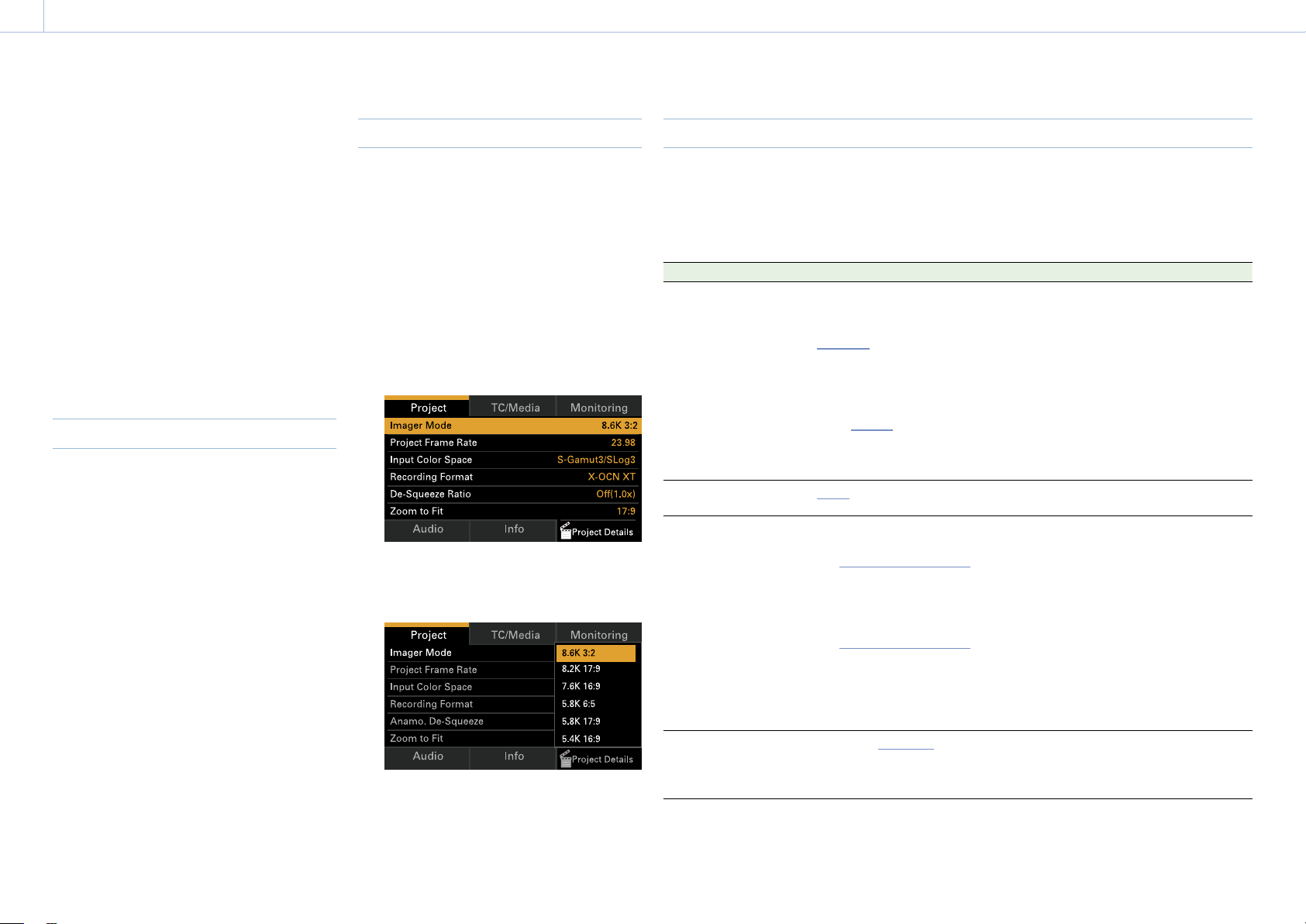
54
3. Camera Operations
Menu Operations
By pressing the MENU button while shooting
(during recording or recording standby) or
during playback, you can display and operate
the menu screen on the sub display.
• Project category: Basic settings and
recording format settings
• TC/Media category: Timecode value and TC
format settings
• Monitoring category: SDI/HDMI/Monitor
external signal output format, OSD, and
marker overlay status settings
• Audio category: Audio source and audio
level settings
• Info category: Camera, media, and battery
status information
Controls
MENU button (page 10)
Press to display the menu on the sub display.
ITEM key 1 to 6 (page 10)
Selects the category of the menu.
SEL/SET dial (MENU dial) (page 10)
Turn to move the cursor in the corresponding
direction to select setting items or setting
values.
Press the MENU dial to apply the selected
item.
BACK button (page 11)
Press to return to the previous menu.
Unconfirmed changes are canceled.
Basic Operation
1 Press the MENU button.
The menu screen appears.
2 Select the category to set using ITEM keys
1 to 6.
3 Turn the MENU dial to move the cursor to
the setting item to select.
For each setting item, the setting value is
displayed.
“Menu Item List” (page 54)
4 Press the MENU dial.
The setting value selection screen
appears next to the selected item.
5 Turn the MENU dial to move the cursor to
the setting value.
6 Press the MENU dial to apply the setting.
Menu Item List
The items available in each category are given below.
Project category
Default values are shown underlined and in bold text.
Item Setting Description
Imager Mode
MPC-3628
8.6K 3:2/8.2K 17:9/
7.6K 16:9/5.8K 6:5/
5.8K 17:9/5.4K 16:9
MPC-3626
6K 3:2/6K 1.85:1/6K 17:9/
6K 2.39:1/5.7K 16:9/4K 6:5/
4K 4:3/4K 4:3 Surround
View/
4K 17:9/
4K 17:9 Surround View/
4K 2.39:1/3.8K 16:9/
3.8K 16:9 Surround View
Sets the effective picture size.
[Notes]
• 5.8K 6:5 is displayed only when an Anamorphic
License is installed.
• 7.6K 16:9/8.2K 17:9/8.6K 3:2 are displayed only
when a Full-Frame License is installed.
• 6K 3:2/6K 1.85:1/6K 17:9/6K 2.39:1/5.7K 16:9
are displayed only when a Full-Frame License is
installed.
• 4K 6:5/4K 4:3/4K 4:3 Surround View are
displayed only when an Anamorphic License is
installed.
Project Frame Rate
23.98/24/25/29.97/47.95/
50/59.94
Sets the project frame rate.
Input Color Space
When RM/RCP Paint Control
(page 91) is set to Off:
S-Gamut3.Cine/SLog3 /
S-Gamut3/SLog3 /
ACEScct
When RM/RCP Paint Control
is set to On:
S-Gamut3.Cine/SLog3 /
S-Gamut3/SLog3 /
ACEScct / HLG(Natural) /
HLG(Live) / Rec.2020/
User Gamma / Rec.709/
User Gamma
Sets the color space.
[Note]
HLG(Natural) is equivalent to HLG BT.2100.
Recording Format
1)
X-OCN XT/X-OCN ST/X-OCN
LT/ProRes 4444 4K/ProRes
4444 QFHD/ProRes 422 HQ
4K/ProRes 422 HQ QFHD
Sets the recording format for AXS memory
cards.
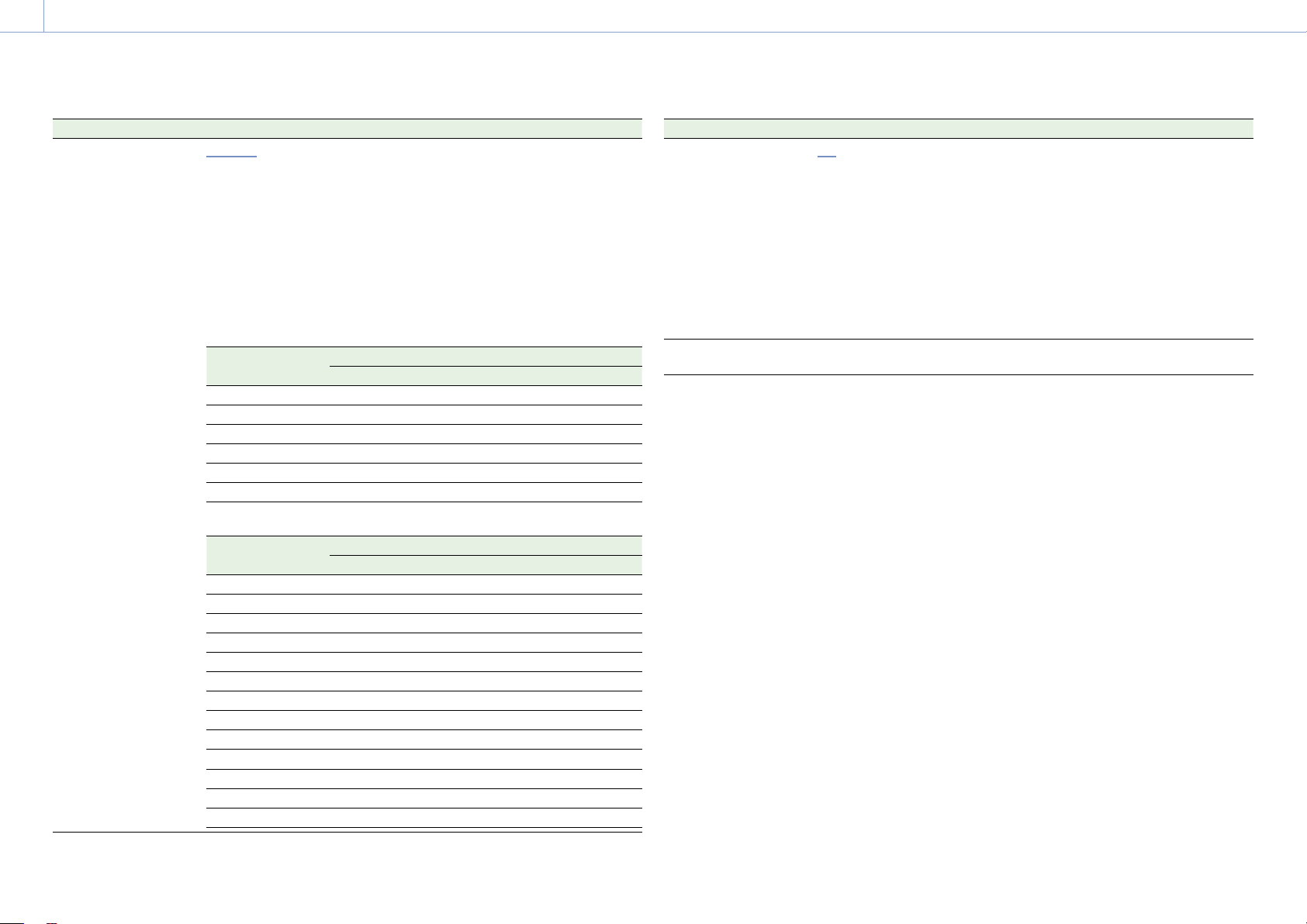
3. Camera Operations: Menu Operations
55
Item Setting Description
Anamo. De-Squeeze
Off(1.0×)/1.25×/1.3×/1.5×/
1.65×/1.8×/2.0×
Sets the de-squeeze processing for ProRes
recording signals and video output signals.
This setting is available when an
Anamorphic License is installed and Imager
Mode is set to 4K 4:3/4K 4:3 Surround
View/4K 6:5/4K 17:9/4K 17:9 Surround
View/5.8K 6:5/5.8K 17:9, or when an
Anamorphic License and Full-Frame License
are installed and Imager Mode is set to 6K
3:2/6K 17:9/8.2K 17:9/8.6K 3:2. The options
vary depending on the picture size.
MPC-3628
Imager Mode Anamo. De-Squeeze
Off(1.0×) 1.25× 1.3× 1.5× 1.65× 1.8× 2.0×
8.6K 3:2 Yes Yes Yes Yes Yes Yes Yes
8.2K 17:9 Yes Yes Yes – Yes Yes Yes
7.6K 16:9 Yes – – – – – –
5.8K 6:5 Yes – – – – – Yes
5.8K 17:9 Yes Yes Yes – Yes Yes Yes
5.4K 16:9 Yes – – – – – –
MPC-3626
Imager Mode Anamo. De-Squeeze
Off(1.0×) 1.25× 1.3× 1.5× 1.65× 1.8× 2.0×
6K 3:2 Yes Yes Yes Yes Yes Yes Yes
6K 1.85:1 Yes – – – – – –
6K 17:9 Yes Yes Yes – Yes Yes Yes
6K 2.39:1 Yes – – – – – –
5.7K 16:9 Yes – – – – – –
4K 6:5 Yes – – – – – Yes
4K 4:3 Surround Yes – Yes – Yes Yes Yes
4K 4:3 Yes – Yes – Yes Yes Yes
4K 17:9 Surround Yes Yes Yes – Yes Yes Yes
4K 17:9 Yes Yes Yes – Yes Yes Yes
4K 2.39:1 Yes – – – – – –
3.8K 16:9 Surround Yes – – – – – –
3.8K 16:9 Yes – – – – – –
Item Setting Description
Zoom to Fit
Off/17:9/16:9 You can set whether to cut out and magnify
the display of the recording image for the
viewfinder screen or Monitor output.
[Notes]
• Configurable under the following conditions.
Imager Mode: 8K 3:2/6K 3:2
Recording Format: X-OCN
Anamo. De-Squeeze: Off(1.0×)
• 16:9 cannot be selected when Project Frame
Rate is set to 47.95.
• If the setting is changed from 17:9 or 16:9 to
Off, the SDI output format returns to the default
setting.
Project Details (ITEM key
6)
Displays the contents of the Project menu
(page 72) in the full menu.
1) The recording formats available vary depending on the combination of the effective picture size and project frame
rate settings. For details about settings, see “Recording Format Settings” (page 59).
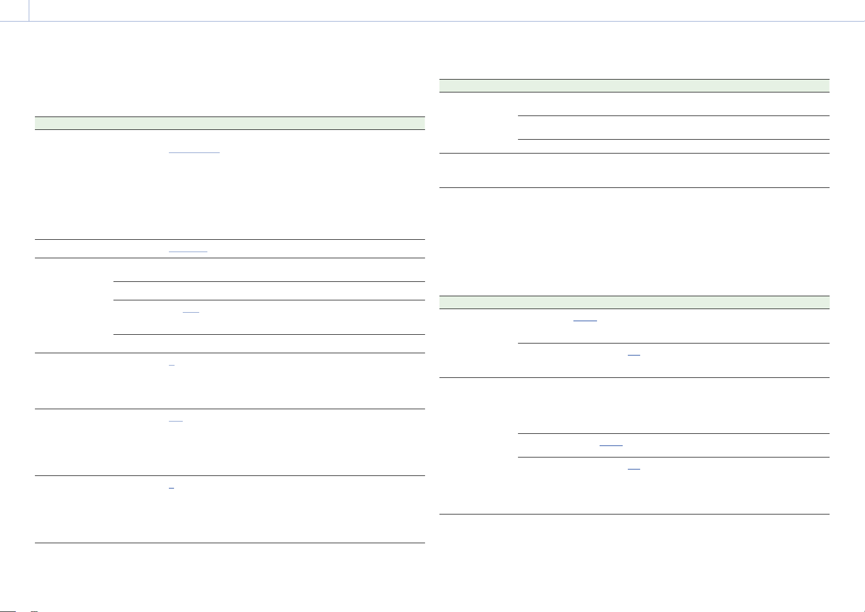
3. Camera Operations: Menu Operations
56
TC/Media category
Default values are shown underlined and in bold text.
Item Setting Description
TC Mode
Preset F-Run (Ext-Lk)/
Preset R-Run/Int Regen
Sets the timecode mode.
Preset F-Run (Ext-Lk): Timecode
advances continuously from specified
value, regardless of whether
recording or not.
Preset R-Run: Timecode advances
from specified value only when
recording.
Int Regen: Timecode continues from
that of the previous clip.
TC Display
Timecode/Duration Switches the time data indication.
TC Setting
(set when
switching to
another screen)
Setting
(H, M, S, F)
Sets the timecode to a desired value.
Reset Resets the timecode to 00:00:00:00.
TC Format
DF/NDF Sets the timecode format.
DF: Drop frame
NDF: Non drop frame
TC Source Internal/External Display only.
Camera ID
A to Z Sets the camera ID used when
generating clip names.
Clip name: Camera ID + Reel Number
+ Shot Number + date + random
string
Reel Number
001 to 999 Sets the numeric portion of the Reel
Number used when generating clip
names.
Clip name: Camera ID + Reel Number
+ Shot Number + date + random
string
Camera Position
C/L/R Sets the first character portion of the
Shot Number used when generating
clip names.
Clip name: Camera ID + Reel Number
+ Shot Number + date + random
string
Item Setting Description
Format Media
(executed when
switching to
another screen)
AXS Slot A Formats the AXS memory card in slot
A.
AXS Slot B Formats the AXS memory card in slot
B.
SD Card Formats the SD card.
Media Details
(ITEM key 6)
Displays the contents of the TC/
Media menu (page 76) in the full
menu.
Monitoring category
Default values are shown underlined and in bold text.
[Notes]
• The unit supports independent configuration of Status Info and Frame Line for each system. The display
information for the A and B output images is configured using the Monitoring menu (page 77).
• Info and Frame Line may not be displayed depending on the Output Format setting. In this case, “–” is displayed
and the setting cannot be changed.
Item Setting Description
VF Overlay
Info A/Info B/Rec Ind./Off Selects the information to display
superimposed on the viewfinder
image.
Frame Line
Line A/Line B/Off Selects the frame lines to display
superimposed on the viewfinder
image.
SDI 1/2 Output
Format
The available settings vary
according to the imager
mode, project frame rate,
and recording format
settings.
Selects the SDI 1/2 output format.
1)
Overlay
Info A/Info B/Rec Ind./Off Information display is not
superimposed on the SDI 1/2 output.
Frame Line
Line A/Line B/Off Selects the frame lines to display
superimposed on the SDI 1/2 output.
[Note]
Frame lines are only superimposed if the
output format is 4K/QFHD.
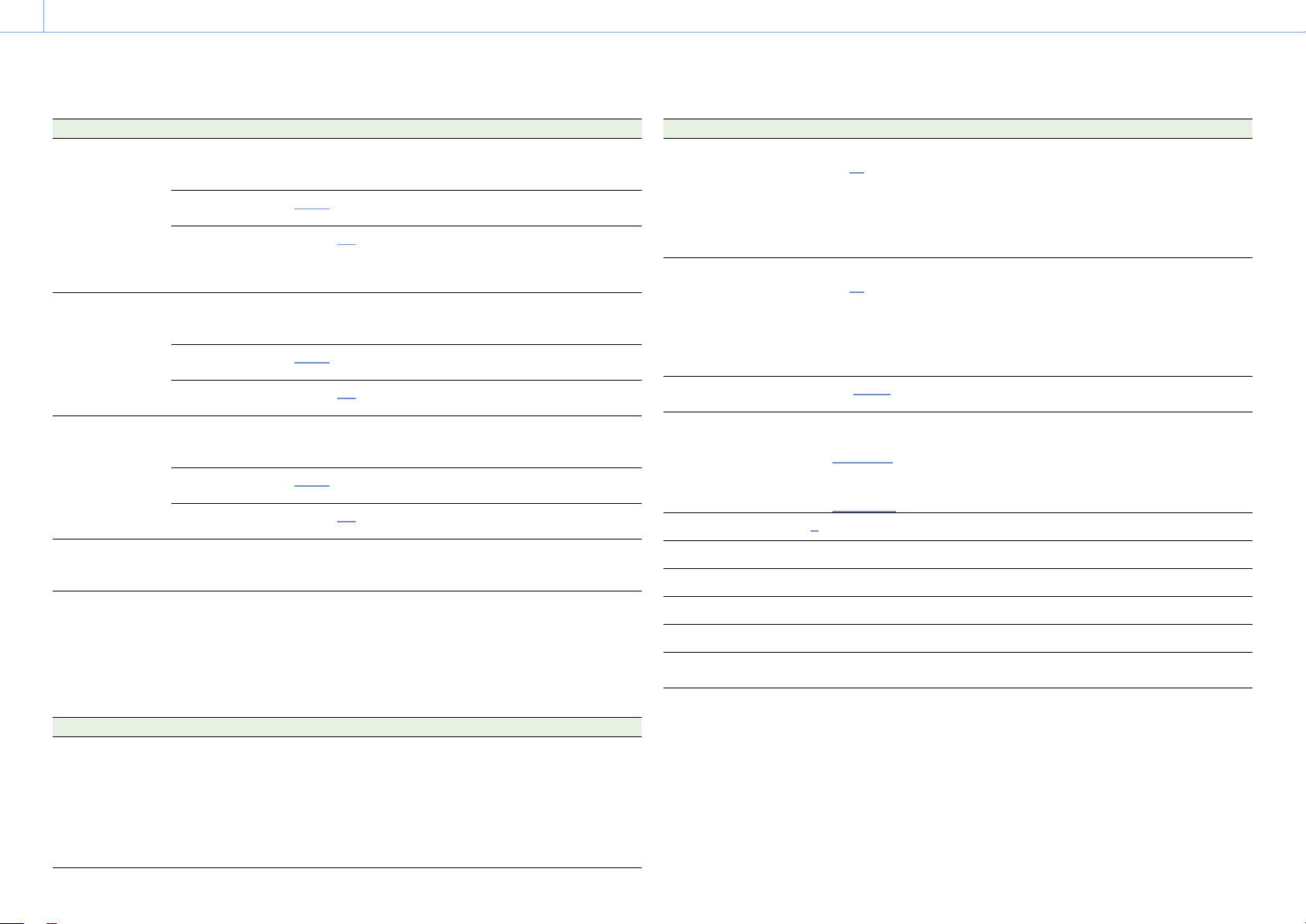
3. Camera Operations: Menu Operations
57
Item Setting Description
SDI 3/4
[Note]
Depending on the
Output Format
setting of SDI 1/2, the
Output Format, Info,
Frame Line settings
of SDI 3/4 may be
blank and cannot be
changed.
Output
Format
The available settings vary
depending on the SDI 1/2
setting.
Selects the SDI 3/4 output format.
1)
Overlay
Info A/Info B/Rec Ind./Off Selects the information to display
superimposed on the SDI 3/4 output.
Frame Line
Line A/Line B/Off Selects the frame lines to display
superimposed on the SDI 3/4 output.
Monitor Output
Format
The available settings vary
depending on the SDI 1/2
setting.
Selects the Monitor output format.
2)
Overlay
Info A/Info B/Rec Ind./Off Selects the information to display
superimposed on the Monitor output.
Frame Line
Line A/Line B/Off Selects the frame lines to display
superimposed on the Monitor output.
HDMI Output
Format
The available settings vary
depending on the SDI 1/2
setting.
Selects the HDMI output format.
2)
Overlay
Info A/Info B/Rec Ind./Off Selects the frame lines to display
superimposed on the HDMI output.
Frame Line
Line A/Line B/Off Selects the information to display
superimposed on the HDMI output.
Moni. Details (ITEM
key 6)
Displays the contents of the
Monitoring menu (page 77) in the
full menu.
1) For details about formats available for selection, see “SDI OUT Connector Output Formats” (page 125).
2) For details about formats available for selection, see “MONITOR OUT Connector/HDMI OUT Connector Output
Formats” (page 130).
Audio category
Default values are shown underlined and in bold text.
Item Setting Description
Source Switch LINE / AES/EBU / MIC Displays the position of the AUDIO IN switch
(page 10) that sets the CH-1 and CH-2
input source.
[Note]
When Audio > Audio Input > Internal Mic Select
(page 84) is set to CH-1/CH-2 in the full menu,
the Source Switch input source is applied to CH-3
and CH-4.
Item Setting Description
XLR Audio L Level
Auto/Manual/Fixed
–99 to
±0 to +99
Automatically adjusts the audio recording
when set to Auto.
The audio recording level is adjusted
manually when set to Manual.
[Note]
Fixed is selected when the Source Switch input
source is AES/EBU.
XLR Audio R Level
Auto/Manual/Fixed
–99 to
±0 to +99
Automatically adjusts the audio recording
when set to Auto.
The audio recording level is adjusted
manually when set to Manual.
[Note]
Fixed is selected when the Source Switch input
source is AES/EBU.
XLR Mic Reference
–60dB/–50dB/–40dB Selects the reference input level of the
microphone.
Monitor CH
When Monitor Output CH
Pair is set to CH-1/CH-2
CH-1/CH-2, CH-1, CH-2
When Monitor Output CH
Pair is set to CH-3/CH-4
CH-3/CH-4, CH-3, CH-4
Selects the audio channel that is output to
the headphones and speaker.
Monitor Level
0 to 99 Adjusts the monitor audio level.
CH1 Level Meter – Displays the CH1 level meter.
CH2 Level Meter – Displays the CH2 level meter.
CH3 Level Meter – Displays the CH3 level meter.
CH4 Level Meter – Displays the CH4 level meter.
Audio Details (ITEM key
6)
Displays the contents of the Audio menu
(page 84) in the full menu.

3. Camera Operations: Menu Operations
58
Checking the Status using the Info Category
You can check the status of media and the battery, and check the contents of warnings and
errors that are issued using the Info category. The contents of the display update in realtime as
the status of the unit changes.
The Info category consists of the following nine information pages. Turn the MENU dial to switch
the page.
No. Page Description
1 Camera Condition Displays warning messages and error messages. When
there are no messages, “All Systems are OK” is displayed at
the top of the display area.
2 Firmware Displays the serial number and firmware version of the unit.
3 License Displays the name and installation status/validity of option
software licenses. If an option is not added, “Not Installed”
or “Expired” is displayed for the installation status.
4 System Displays the following system information.
• Date and time
• Fan rotation speed
• Sensor detection temperature
• Hours meter
• IP Address
[Notes]
• If the sensor detection temperature reaches 65 °C (149 °F), a high
temperature warning message is issued.
• “0.0.0.0” is displayed if the IP address cannot be obtained.
5 Battery Displays the following battery information.
• Detected battery name or type
• Remaining capacity (%)
• Estimated remaining time
• Remaining capacity (Ah)
• Voltage (V)
• Number of times that the battery has been charged
• Power source
• Supplied power source voltage
6 Media Displays the remaining capacity, remaining recording time,
and lifespan data of AXS memory cards and SD cards.
No. Page Description
7 Lens Displays the following information for the lens attached to
the unit.
• Lens model name
• T value of iris
[Note]
The F-stop value is displayed instead of the T-stop value if the
T-stop value cannot be obtained.
• Focal length
• Focus distance
• Depth of field
• Serial number
8 Network Displays the network connection setup information.
• Status (LAN/Wireless Access Point/Wireless Station/Off)
• IP Address
• SSID
• MAC Address
[Note]
“0.0.0.0” is displayed if the IP address cannot be obtained.
9 False Color Setting Table Displays the following False Color setup information.
• Set color
• Setting minimum value to maximum value
• Description
[Note]
If the setting minimum value to maximum value is different from
the initial values, the text color becomes gray.
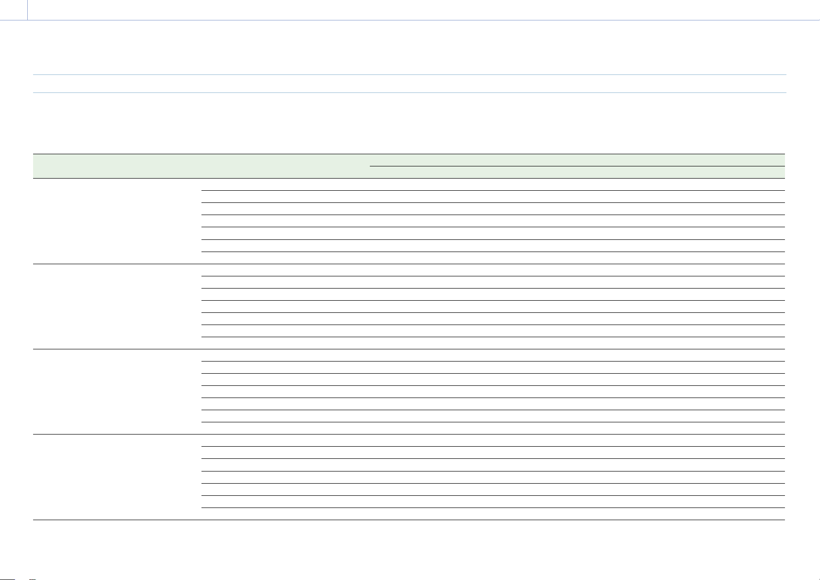
3. Camera Operations: Menu Operations
59
Recording Format Settings
The following recording formats can be selected for different combinations of effective picture size and project frame rate settings.
MPC-3628
Effective picture size (Imager Mode) Recording format Project Frame Rate
23.98 24.00 25.00 29.97 47.95 50.00 59.94
8.6K 3:2 X-OCN XT Yes Yes Yes Yes – – –
X-OCN ST Yes Yes Yes Yes – – –
X-OCN LT Yes Yes Yes Yes – – –
4K ProRes 4444 – – – – – – –
QFHD ProRes 4444 – – – – – – –
4K ProRes 422 HQ – – – – – – –
QFHD ProRes 422 HQ – – – – – – –
8.2K 17:9 X-OCN XT Yes Yes Yes Yes – – –
X-OCN ST Yes Yes Yes Yes Yes Yes Yes
X-OCN LT Yes Yes Yes Yes Yes Yes Yes
4K ProRes 4444 Yes Yes Yes Yes – Yes Yes
QFHD ProRes 4444 – – – – – – –
4K ProRes 422 HQ Yes Yes Yes Yes – Yes Yes
QFHD ProRes 422 HQ – – – – – – –
7.6K 16:9 X-OCN XT Yes Yes Yes Yes – – –
X-OCN ST
Yes Yes Yes Yes – Yes Yes
X-OCN LT Yes Yes Yes Yes – Yes Yes
4K ProRes 4444 – – – – – – –
QFHD ProRes 4444 Yes Yes Yes Yes – Yes Yes
4K ProRes 422 HQ – – – – – – –
QFHD ProRes 422 HQ Yes Yes Yes Yes – Yes Yes
5.8K 6:5 X-OCN XT Yes Yes Yes Yes Yes – –
X-OCN ST Yes Yes Yes Yes Yes – –
X-OCN LT Yes Yes Yes Yes Yes – –
4K ProRes 4444 Yes Yes Yes Yes – – –
QFHD ProRes 4444 – – – – – – –
4K ProRes 422 HQ Yes Yes Yes Yes – – –
QFHD ProRes 422 HQ – – – – – – –
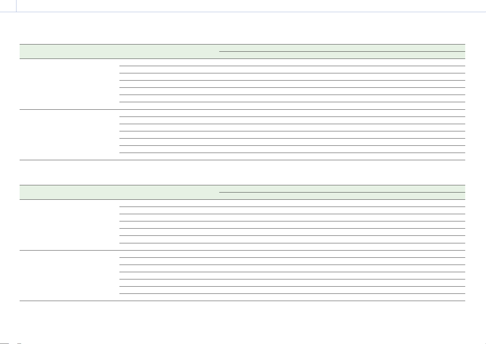
3. Camera Operations: Menu Operations
60
Effective picture size (Imager Mode) Recording format Project Frame Rate
23.98 24.00 25.00 29.97 47.95 50.00 59.94
5.8K 17:9 X-OCN XT Yes Yes Yes Yes Yes Yes Yes
X-OCN ST Yes Yes Yes Yes Yes Yes Yes
X-OCN LT Yes Yes Yes Yes Yes Yes Yes
4K ProRes 4444 Yes Yes Yes Yes – Yes Yes
QFHD ProRes 4444 – – – – – – –
4K ProRes 422 HQ Yes Yes Yes Yes – Yes Yes
QFHD ProRes 422 HQ – – – – – – –
5.4K 16:9 X-OCN XT Yes Yes Yes Yes – Yes Yes
X-OCN ST Yes Yes Yes Yes – Yes Yes
X-OCN LT Yes Yes Yes Yes – Yes Yes
4K ProRes 4444 – – – – – – –
QFHD ProRes 4444 Yes Yes Yes Yes – Yes Yes
4K ProRes 422 HQ – – – – – – –
QFHD ProRes 422 HQ Yes Yes Yes Yes – Yes Yes
MPC-3626
Effective picture size (Imager Mode) Recording format Project Frame Rate
23.98 24.00 25.00 29.97 47.95 50.00 59.94
6K 3:2 X-OCN XT Yes Yes Yes Yes Yes Yes Yes
X-OCN ST Yes Yes Yes Yes Yes Yes Yes
X-OCN LT Yes Yes Yes Yes Yes Yes Yes
4K ProRes 4444 – – – – – – –
QFHD ProRes 4444 – – – – – – –
4K ProRes 422 HQ – – – – – – –
QFHD ProRes 422 HQ – – – – – – –
6K 1.85:1 X-OCN XT Yes Yes Yes Yes Yes Yes Yes
X-OCN ST Yes Yes Yes Yes Yes Yes Yes
X-OCN LT Yes Yes Yes Yes Yes Yes Yes
4K ProRes 4444 – – – – – – –
QFHD ProRes 4444 – – – – – – –
4K ProRes 422 HQ – – – – – – –
QFHD ProRes 422 HQ – – – – – – –
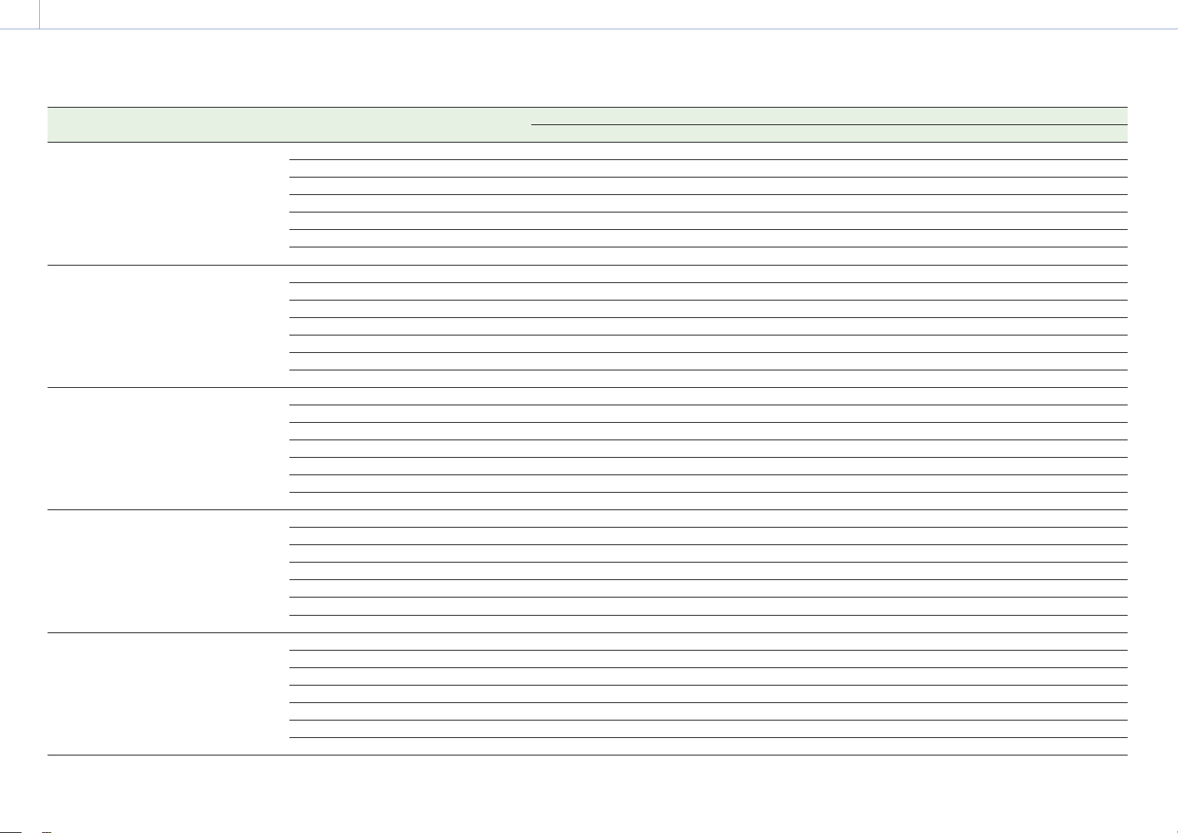
3. Camera Operations: Menu Operations
61
Effective picture size (Imager Mode) Recording format Project Frame Rate
23.98 24.00 25.00 29.97 47.95 50.00 59.94
6K 17:9 X-OCN XT Yes Yes Yes Yes Yes Yes Yes
X-OCN ST Yes Yes Yes Yes Yes Yes Yes
X-OCN LT Yes Yes Yes Yes Yes Yes Yes
4K ProRes 4444 Yes Yes Yes Yes – Yes Yes
QFHD ProRes 4444 – – – – – – –
4K ProRes 422 HQ Yes Yes Yes Yes – Yes Yes
QFHD ProRes 422 HQ – – – – – – –
6K 2.39:1 X-OCN XT Yes Yes Yes Yes Yes Yes Yes
X-OCN ST Yes Yes Yes Yes Yes Yes Yes
X-OCN LT Yes Yes Yes Yes Yes Yes Yes
4K ProRes 4444 Yes Yes Yes Yes – Yes Yes
QFHD ProRes 4444 – – – – – – –
4K ProRes 422 HQ Yes Yes Yes Yes – Yes Yes
QFHD ProRes 422 HQ – – – – – – –
5.7K 16:9 X-OCN XT Yes Yes Yes Yes – Yes Yes
X-OCN ST
Yes Yes Yes Yes – Yes Yes
X-OCN LT Yes Yes Yes Yes – Yes Yes
4K ProRes 4444 – – – – – – –
QFHD ProRes 4444 Yes Yes Yes Yes – Yes Yes
4K ProRes 422 HQ – – – – – – –
QFHD ProRes 422 HQ Yes Yes Yes Yes – Yes Yes
4K 6:5 X-OCN XT Yes Yes Yes Yes Yes Yes Yes
X-OCN ST Yes Yes Yes Yes Yes Yes Yes
X-OCN LT Yes Yes Yes Yes Yes Yes Yes
4K ProRes 4444 Yes Yes Yes Yes – Yes Yes
QFHD ProRes 4444 – – – – – – –
4K ProRes 422 HQ Yes Yes Yes Yes – Yes Yes
QFHD ProRes 422 HQ – – – – – – –
4K 4:3 X-OCN XT Yes Yes Yes Yes Yes Yes Yes
X-OCN ST Yes Yes Yes Yes Yes Yes Yes
X-OCN LT Yes Yes Yes Yes Yes Yes Yes
4K ProRes 4444 – – – –
– – –
QFHD ProRes 4444 – – – – – – –
4K ProRes 422 HQ – – – – – – –
QFHD ProRes 422 HQ – – – – – – –

3. Camera Operations: Menu Operations
62
Effective picture size (Imager Mode) Recording format Project Frame Rate
23.98 24.00 25.00 29.97 47.95 50.00 59.94
4K 4:3 Surround X-OCN XT Yes Yes Yes Yes – – –
X-OCN ST Yes Yes Yes Yes – – –
X-OCN LT Yes Yes Yes Yes – – –
4K ProRes 4444 – – – – – – –
QFHD ProRes 4444 – – – – – – –
4K ProRes 422 HQ – – – – – – –
QFHD ProRes 422 HQ – – – – – – –
4K 17:9 X-OCN XT Yes Yes Yes Yes Yes Yes Yes
X-OCN ST Yes Yes Yes Yes Yes Yes Yes
X-OCN LT Yes Yes Yes Yes Yes Yes Yes
4K ProRes 4444 Yes Yes Yes Yes – Yes Yes
QFHD ProRes 4444 – – – – – – –
4K ProRes 422 HQ Yes Yes Yes Yes – Yes Yes
QFHD ProRes 422 HQ – – – – – – –
4K 17:9 Surround X-OCN XT Yes Yes Yes Yes – – –
X-OCN ST
Yes Yes Yes Yes – – –
X-OCN LT Yes Yes Yes Yes – – –
4K ProRes 4444 Yes Yes Yes Yes – – –
QFHD ProRes 4444 – – – – – – –
4K ProRes 422 HQ Yes Yes Yes Yes – – –
QFHD ProRes 422 HQ – – – – – – –
4K 2.39:1 X-OCN XT Yes Yes Yes Yes Yes Yes Yes
X-OCN ST Yes Yes Yes Yes Yes Yes Yes
X-OCN LT Yes Yes Yes Yes Yes Yes Yes
4K ProRes 4444 Yes Yes Yes Yes – Yes Yes
QFHD ProRes 4444 – – – – – – –
4K ProRes 422 HQ Yes Yes Yes Yes – Yes Yes
QFHD ProRes 422 HQ – – – – – – –
3.8K 16:9 X-OCN XT Yes Yes Yes Yes – Yes Yes
X-OCN ST Yes Yes Yes Yes – Yes Yes
X-OCN LT Yes Yes Yes Yes – Yes Yes
4K ProRes 4444 – – – –
– – –
QFHD ProRes 4444 Yes Yes Yes Yes – Yes Yes
4K ProRes 422 HQ – – – – – – –
QFHD ProRes 422 HQ Yes Yes Yes Yes – Yes Yes
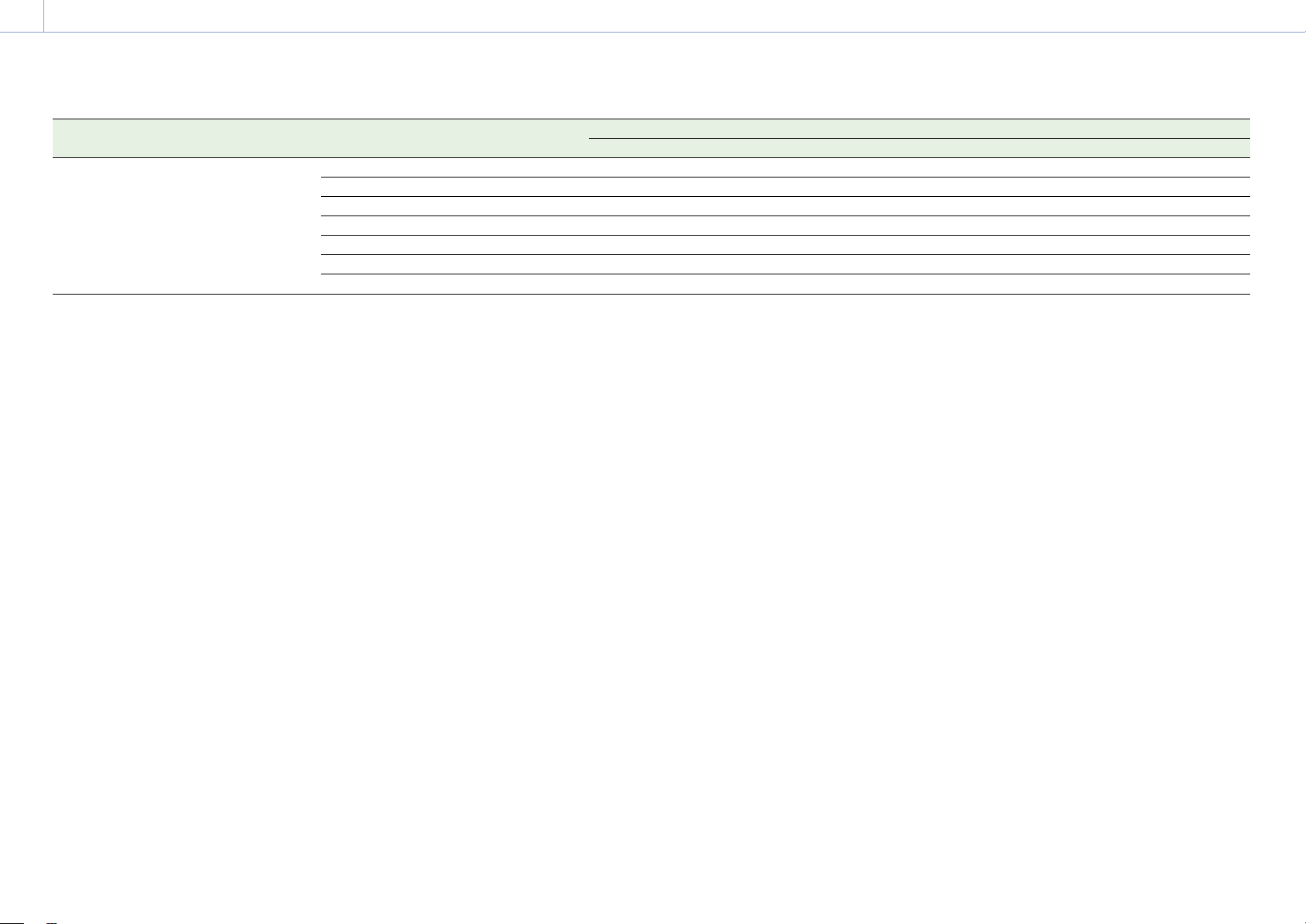
3. Camera Operations: Menu Operations
63
Effective picture size (Imager Mode) Recording format Project Frame Rate
23.98 24.00 25.00 29.97 47.95 50.00 59.94
3.8K 16:9 Surround X-OCN XT Yes Yes Yes Yes – – –
X-OCN ST Yes Yes Yes Yes – – –
X-OCN LT Yes Yes Yes Yes – – –
4K ProRes 4444 – – – – – – –
QFHD ProRes 4444 Yes Yes Yes Yes – – –
4K ProRes 422 HQ – – – – – – –
QFHD ProRes 422 HQ Yes Yes Yes Yes – – –

64
3. Camera Operations
Full Menu Operations
The full menu for configuring the required
settings for shooting and playback is
displayed on the sub display be pressing and
holding the MENU button for 2 seconds or
longer.
You can also press the MENU button together
with the MENU dial to quickly display the full
menu screen.
Menu Structure
Shooting menu
Menu used to make settings related to
shooting.
Project menu
Menu used to make basic settings for a
project.
TC/Media menu
Menu used to make settings related to
timecode and recording media.
Monitoring menu
Menu used to make settings related to video
output and viewfinder output.
Audio menu
Menu used to make settings related to audio.
Paint menu
Menu used to make settings related to paint
functions.
The Paint menu can be displayed and selected
only when Technical > Special Configuration >
RM/RCP Paint Control (page 91) is set to On
in the full menu.
Technical menu
Menu used to make settings related to
technical matters.
Maintenance menu
Menu used to make unit settings, such as the
clock and language settings.
Controls
MENU button (page 10)
Press and hold for 2 seconds or longer to
display the full menu on the sub display.
SEL/SET dial (MENU dial) (page 10)
Turn to move the cursor in the corresponding
direction to select setting items or setting
values.
Press the MENU dial to apply the selected
item.
BACK button (page 11)
Press to return to the previous menu.
Unconfirmed changes are canceled.
Setting Menu Items
Turn the MENU dial to move the cursor to the
menu item you want to set, then press the
MENU dial to select that item.
• The menu item selection area can show
a maximum of nine lines. When all the
selectable items cannot be displayed at one
time, you can scroll the display up or down
by moving the cursor.
• For items having a wide range of available
values (example: –99 to +99), the selection
area is not displayed. The current setting is
highlighted to indicate that the value can be
changed.
• If you select Run for an executable item, the
corresponding function is executed.
• When you select an item that you must
confirm before execution, a confirmation
message appears. Follow the instructions
in the message to execute or cancel the
operation.
65
3. Camera Operations
Shooting Menu
The functions and available settings of each menu item are given below.
Default values are shown underlined and in
bold text.
Shooting > FPS
Sets the shooting frame rate.
Menu item Setting Description
Fixed/Variable Select
Fixed/Variable Selects whether the FPS setting is set to
constant speed shooting or variable speed
shooting.
FPS Select When Fixed/Variable Select is
set to Fixed, one of the
following values is displayed.
Fixed 23.98/Fixed 24.00/
Fixed 25.00/Fixed 29.97/
Fixed 47.95/Fixed 50.00/
Fixed 59.94
Selects the shooting frame rate.
The default values vary as shown below
depending on the Project Frame Rate setting.
Project
Frame
Rate
Default when
Fixed/Variable
Select is
Variable
Display value
when Fixed/
Variable Select
is Fixed
59.94 60 Fixed 59.94
50 50 Fixed 50.00
47.95 48 Fixed 47.95
29.97 30 Fixed 29.97
25 25 Fixed 25.00
24 24 Fixed 24.00
23.97 24 Fixed 23.98
[Note]
Shooting frame rates of 7 or lower cannot be set in
the following cases.
– When Base ISO is set to ISO 3200
– When Base ISO is set to ISO 2500 and the
recording format is ProRes
Shooting > Shutter
Makes settings related to the electronic shutter.
[Note]
Shutter is grayed out and cannot be operated when an RM-B170 or other remote control unit is connected and
Technical > Special Configuration > RM/RCP Paint Control (page 91) is set to On in the full menu.
Menu item Setting Description
Shutter Select
When Shutter Mode
(page 87) is set to Speed
Default selection options
1/24, 1/25, 1/30, 1/48, 1/50,
1/60, 1/100, 1/120, 1/250,
1/500, 1/1000, 1/2000
1)
When Shutter Mode
(page 87) is set to Angle
Default selection options
360.0/
180.0/172.8/144.0/
90.0/45.0/22.5/11.2/5.6
When Step/Cont. Select is set
to Continuous, the selection
range is 360.0 to 4.2 (Angle) or
1/24
1)
to 1/8000
2)
(Speed).
Selects shutter angle or speed of the
electronic shutter.
The default speed values for different Project
Frame Rate (page 72) settings are given
below.
23.98/24: 1/24
25: 1/25
29.97: 1/30
47.95: 1/48
50: 1/50
59.94: 1/60
1) The options are 1/60 and subsequent values
when the project frame rate is 59.94, 1/50
and subsequent values when 50.0, 1/30 and
subsequent values when 29.97, and 1/25 and
subsequent values when 25.0.
2) The options are 1/7000 and preceding values
when the project frame rate is 50.0 or 25.0, and
1/6000 and preceding values when 24.0 or 23.98.
Step/Cont. Select
Step/Continuous Selects whether the electronic shutter values
are step values or continuous.
Add/Change Step Adds or edits a selection option available in
Shutter Select in Step mode.
Up to 16 selection options can be added.
Delete Step Deletes a selection option available in Shutter
Select in Step mode.
Shooting > Flicker Reduce
Makes settings related to flicker reduction.
Menu item Setting Description
Mode
On/Off Turns the flicker reduction function on/off.
Frequency
50Hz/60Hz Sets the power supply frequency of lighting
causing flicker.

3. Camera Operations: Shooting Menu
66
Shooting > ND
Sets the ND filter position.
Menu item Setting Description
ND Position
Clear/0.3/0.6/0.9/1.2/1.5/1.8/
2.1/2.4
Selects the density of the ND filter.
Shooting > Exposure Index
Sets the EI value.
[Note]
Exposure Index is grayed out and the setting cannot be changed when Technical > Special Configuration > RM/RCP
Paint Control (page 91) is set to On in the full menu.
Menu item Setting Description
EI Select
The settings change as follows
depending on the Project >
Basic Setting > Base ISO
(page 72) setting in the full
menu.
MPC-3628
Base ISO 800:
200EI/250EI/320EI/400EI/
500EI/640EI/
800EI/
1000EI/1250EI/1600EI/
2000EI/2500EI/3200EI
Base ISO 3200:
800EI/1000EI/1250EI/
1600EI/2000EI/2500EI/
3200EI/4000EI/5000EI/
6400EI/8000EI/10000EI/
12800EI
MPC-3626
ISO 500:
125EI/160EI/200EI/250EI/
320EI/400EI/
500EI/640EI/
800EI/1000EI/1250EI/
1600EI/2000EI
ISO 2500:
640EI/800EI/1000EI/
1250EI/1600EI/2000EI/
2500EI/3200EI/4000EI/
5000EI/6400EI/8000EI/
10000EI
Selects the EI value.
[Note]
The settings are fixed to the following values when
Technical > Special Configuration > RM/RCP Paint
Control (page 91) is set to On in the full menu.
When Base ISO is set to ISO500: 500EI
When Base ISO is set to ISO2500: 2500EI
When Base ISO is set to ISO800: 800EI
When Base ISO is set to ISO3200: 3200EI
Shooting > Gain
Makes settings related to the gain.
[Note]
Gain setting cannot be changed when an RM-B170 or other remote control unit is connected or Technical > Special
Configuration > RM/RCP Paint Control (page 91) is set to Off in the full menu.
Menu item Setting Description
Gain Select
–6dB/–3dB/0dB/3dB/6dB/
9dB/12dB/15dB/18dB
Sets the base sensitivity.
Shooting > White Balance
Makes settings related to white balance.
[Note]
White Balance is grayed out and cannot be operated when an RM-B170 or other remote control unit is connected
and Technical > Special Configuration > RM/RCP Paint Control (page 91) is set to On in the full menu.
Menu item Setting Description
Color Temp. Select
3200K+00/4300K+00/
5500K+00
+ other added options (up to
16)
Displays and selects the color temperature/
color tone of the white balance.
Add/Change Step Adds or edits a selection option by changing
the color temperature and tint value of white
balance.
Delete Step Deletes an added selection option.
Auto White Balance Run/Cancel Executes auto white balance (execute by
selecting Run).
Shooting > Look
Makes settings related to Preset Look.
[Note]
Look is grayed out and the setting cannot be changed when Technical > Special Configuration > RM/RCP Paint
Control (page 91) is set to On in the full menu.
Menu item Setting Description
Category
Preset Look/User 3D LUT/
ART/ACEScct with User 3D/
ACESproxy with User 3D/ACES
with ART
Selects the LUT category.
[Note]
ACEScct with User 3D/ACESproxy with User 3D/ACES
with ART can be selected only when Project > Basic
Setting > Input Color Space (page 72) is set to
ACEScct in the full menu.

3. Camera Operations: Shooting Menu
67
Shooting > Look
Makes settings related to Preset Look.
[Note]
Look is grayed out and the setting cannot be changed when Technical > Special Configuration > RM/RCP Paint
Control (page 91) is set to On in the full menu.
Menu item Setting Description
Preset Look Select
s709/R709(800%) /
S-Gamut3.Cine/SLog3 /
S-Gamut3/SLog3 /
ACESproxy / ACEScct /
ACES 1.0 Output-Rec.709
Selects the Preset Look.
Outputs images that are suitable as the
starting point for color grading or images that
are close to print film quality.
s709: Cinema color
R709(800%): Faithful color
S-Gamut3/SLog3: Wide color space
S-Gamut3.Cine/SLog3: Color space for digital
cinema
ACESproxy: Log curve of wide color space
(AP1) defined by the Academy.
ACEScct: Log curve of wide color space (AP1)
based on ACESproxy, with toe
characteristic that reduces contrast in the
curve near black.
ACES 1.0 Output-Rec.709: Rec.709 reference
Look defined by the Academy.
[Notes]
• Configurable only when Category is set to Preset
Look.
• S-Gamut3/SLog3 can be selected only when
Project > Basic Setting > Input Color Space
(page 72) is set to S-Gamut3/SLog3 in the full
menu.
• ACESproxy/ACEScct/ACES 1.0 Output-Rec.709 can
be selected only when Project > Basic Setting >
Input Color Space (page 72) is set to ACEScct in
the full menu.
User 3D LUT Select File name (01 to 16) of User 3D
LUT files stored in internal
memory
Selects the User 3D LUT file.
[Note]
Configurable only when Category is set to User 3D
LUT, ACEScct with User 3D, or ACESproxy with User
3D.
ART Select File name (01 to 16) of ART
files stored in internal memory
Selects the ART file.
[Note]
Configurable only when Category is set to ART or
ACES with ART.
Shooting > Look
Makes settings related to Preset Look.
[Note]
Look is grayed out and the setting cannot be changed when Technical > Special Configuration > RM/RCP Paint
Control (page 91) is set to On in the full menu.
Menu item Setting Description
ART Information Displays information from the ART file
selected by ART Select.
[Note]
Displayed only when Category is set to ART or ACES
with ART.
ASC CDL Process
CDL Off/Look-> CDL/CDL ->
Look/CDL On
Sets whether to apply ASC CDL to the output
video. When applying, specify the ASC CDL
processing sequence.
CDL Off: Do not apply ASC CDL to the output
video.
Look -> CDL: Apply CDL after applying Look.
CDL -> Look: Apply CDL before applying Look.
CDL On: Apply ASC CDL to the output video.
[Notes]
• ASC CDL is enabled for outputs for which Look is
selected in Shooting > LUT Select (page 68) in
the full menu.
• The conditions under which the ASC CDL Process
options are enabled are given in the following
table.
3. Camera Operations: Shooting Menu
68
Shooting > Look
Makes settings related to Preset Look.
[Note]
Look is grayed out and the setting cannot be changed when Technical > Special Configuration > RM/RCP Paint
Control (page 91) is set to On in the full menu.
Menu item Setting Description
ASC CDL Process
Shooting > Look
Project > Basic Setting >
Input Color Space
ASC CDL Process
available options
Category Preset Look Select
Preset Look s709 S-Gamut3/Slog3
S-Gamut3.Cine/Slog3
CDL Off
Look -> CDL
CDL -> Look
R709(800%)
S-Gamut3/Slog3
S-Gamut3/Slog3
S-Gamut3.Cine/Slog3
CDL Off
Look -> CDL
S-Gamut3.Cine/
Slog3
S-Gamut3/Slog3 CDL Off
Look -> CDL
S-Gamut3.Cine/Slog3 CDL Off
Look -> CDL
ACESproxy
ACEScct
ACES 1.0
Output-Rec.709
ACEScct CDL Off
CDL On
User 3D
LUT
– S-Gamut3/Slog3
S-Gamut3.Cine/Slog3
CDL Off
Look -> CDL
CDL -> Look
ART – S-Gamut3/Slog3
S-Gamut3.Cine/Slog3
CDL Off
Look -> CDL
CDL -> Look
ACEScct
with User
3D
ACESproxy
with User
3D
– ACEScct CDL Off
CDL -> Look
ACES with
ART
– ACEScct CDL Off
CDL -> Look
ASC CDL Select
No File/Not Selected Selects the ASC CDL registered in the unit.
ASC CDL Information Displays information from the ASC CDL file
selected by ASC CDL Select.
You can change the Saturation setting on the
displayed screen.
Shooting > Look File
Loads a User 3D LUT file into the unit.
[Note]
Look File is grayed out and the setting cannot be changed when Technical > Special Configuration > RM/RCP Paint
Control (page 91) is set to On in the full menu.
Menu item Setting Description
Load User 3D LUT Loads a User 3D LUT file stored on an SD card
into the unit.
Reset User 3D LUT Resets a User 3D LUT data setting.
Reset All User 3D
LUTs
Run/Cancel Resets all User 3D LUT data settings (execute
by selecting Run).
Load ART Loads an ART file stored on an SD card into
the unit.
Reset ART Resets an ART data setting.
Reset All ARTs Run/Cancel Resets all ART data settings (execute by
selecting Run).
Load ASC CDL Loads ASC CDL data from an SD card.
Reset ASC CDL Resets an ASC CDL data setting.
Reset All ASC CDLs Run/Cancel Resets all ASC CDL data settings (execute by
selecting Run).
Shooting > LUT Select
Makes settings related to the LUT to apply to the output image.
[Note]
The value of each menu item (excluding SDR Gain) varies depending on the Technical > Special Configuration > RM/
RCP Paint Control (page 91) setting in the full menu.
Menu item Setting Description
SDI 1/2
When RM/RCP Paint Control is
set to Off:
Log/
Look
Selects the LUT to apply to the SDI 1/2 output
image.
When RM/RCP Paint Control is
set to On:
Log/HLG(Natural)/
HLG(Live)/User Gamma
The SDI 1/2 output image setting is display
only, because it is determined by the Project >
Basic Setting > Input Color Space (page 72)
setting in the full menu.

3. Camera Operations: Shooting Menu
69
Shooting > LUT Select
Makes settings related to the LUT to apply to the output image.
[Note]
The value of each menu item (excluding SDR Gain) varies depending on the Technical > Special Configuration > RM/
RCP Paint Control (page 91) setting in the full menu.
Menu item Setting Description
SDI 3/4
When RM/RCP Paint Control is
set to Off:
Log/
Look
Selects the LUT to apply to the SDI 3/4 output
image.
[Note]
When SDI 1/2 output is the following, this is set to
the same value as SDI 1/2 (fixed).
– 4K/QFHD Quad output
– 4K/QFHD Dual output
When SDI 1/2 output is the following, this is set to
the same value as Monitor (fixed).
– 4K/QFHD 12G/6G output
– 4K/QFHD Dual output
When RM/RCP Paint Control is
set to On:
Log/HLG(Natural)/
HLG(Live)/User Gamma
The SDI 3/4 output image setting is display
only, because it is determined by the Project >
Basic Setting > Input Color Space (page 72)
setting in the full menu.
[Note]
When SDI 1/2 output is the following, this is set to
the same value as Monitor (fixed).
– 4K/QFHD 12G/6G output
– 4K/QFHD Dual output
When SDI 1/2 output is the following, this is set to
the same value as SDI 1/2 (fixed).
– 4K/QFHD Quad output
– 4K/QFHD Dual output
Shooting > LUT Select
Makes settings related to the LUT to apply to the output image.
[Note]
The value of each menu item (excluding SDR Gain) varies depending on the Technical > Special Configuration > RM/
RCP Paint Control (page 91) setting in the full menu.
Menu item Setting Description
Monitor
When RM/RCP Paint Control is
set to Off:
When Output Format > SDI
1/2 is set to 2K/HD:
Log/
s709/R709(800%)/
Look/---
When Output Format > SDI
1/2 is set to 4K/QFHD:
Log/s709/R709(800%)/
Look/---
Selects the LUT to apply to the Monitor output
image.
[Note]
There is no output and “---” (disabled) is displayed
when Technical > Special Configuration > SD HDMI
(page 91) is set to On in the full menu.
When RM/RCP Paint Control is
set to On, the settings change
as follows depending on the
Project > Basic Setting > Input
Color Space (page 72)
setting in the full menu.
S-Gamut3.Cine/SLog3 or
S-Gamut3/SLog3:
Log/R709(800%)
HLG(Natural):
HLG(Natural)/R709(800%)
HLG(Live):
HLG(Live)/R709(800%)
Rec.2020/User Gamma:
User Gamma/R709-Like
Rec.709/User Gamma:
User Gamma
Selects the type of Monitor output image.
[Notes]
• An SDR gain value (–12 dB) is applied to the
viewfinder/monitor output image.
• You can change the output gain using SDR Gain
when set to R709(800%) or R709-Like.
3. Camera Operations: Shooting Menu
70
Shooting > LUT Select
Makes settings related to the LUT to apply to the output image.
[Note]
The value of each menu item (excluding SDR Gain) varies depending on the Technical > Special Configuration > RM/
RCP Paint Control (page 91) setting in the full menu.
Menu item Setting Description
HDMI
When RM/RCP Paint Control is
set to Off (4K/QFHD output):
Log/
Look
Display only, because the HDMI output image
setting is the same as SDI 1/2.
When RM/RCP Paint Control is
set to Off (2K/HD output):
Log/
s709/R709(800%)/
Look
Display only, because the HDMI output image
setting is the same as Monitor.
[Note]
Set to Log (fixed) when Technical > Special
Configuration > SD HDMI (page 91) is set to On in
the full menu.
When RM/RCP Paint Control is
set to On (4K/QFHD output):
Log/HLG(Natural)/
HLG(Live)/User Gamma
Display only, because the HDMI output image
setting is the same as SDI 1/2.
When RM/RCP Paint Control is
set to On (2K/HD output):
Log/HLG(Natural)/
HLG(Live)/User Gamma/
R709(800%)/R709-Like
Display only, because the HDMI output image
setting is the same as Monitor.
Shooting > LUT Select
Makes settings related to the LUT to apply to the output image.
[Note]
The value of each menu item (excluding SDR Gain) varies depending on the Technical > Special Configuration > RM/
RCP Paint Control (page 91) setting in the full menu.
Menu item Setting Description
VF LUT
When RM/RCP Paint Control is
set to Off:
Log/
s709/R709(800%)/
Look
Selects the LUT to apply to the viewfinder/
monitor screen output image.
When RM/RCP Paint Control is
set to On:
The settings change as
follows depending on the
Project > Basic Setting >
Input Color Space
(page 72) setting in the
full menu.
S-Gamut3.Cine/SLog3 or
S-Gamut3/SLog3:
Log/
R709(800%)
HLG(Natural):
HLG(Natural)/
R709(800%)
HLG(Live):
HLG(Live)/
R709(800%)
Rec.2020/User Gamma:
User Gamma/
R709-Like
Rec.709/User Gamma:
User Gamma
Selects the type of viewfinder/monitor screen
output image.
[Notes]
• An SDR gain value (–12 dB) is applied to the
viewfinder/monitor output image.
• You can change the output gain using SDR Gain
when set to R709(800%) or R709-Like.
ProRes
When RM/RCP Paint Control is
set to Off:
Log/Look/---
Selects the LUT to apply to the ProRes
recording image.
[Note]
“---” (disabled) is displayed when Project > Basic
Setting > Recording Format (page 72) is set to
X-OCN format in the full menu.
When RM/RCP Paint Control is
set to On:
Log/HLG(Natural)/
HLG(Live)/User Gamma
The ProRes recording image setting is display
only, because it is determined by the Project >
Basic Setting > Input Color Space (page 72)
setting in the full menu.

3. Camera Operations: Shooting Menu
71
Shooting > LUT Select
Makes settings related to the LUT to apply to the output image.
[Note]
The value of each menu item (excluding SDR Gain) varies depending on the Technical > Special Configuration > RM/
RCP Paint Control (page 91) setting in the full menu.
Menu item Setting Description
SDR Gain
–15dB to 0dB (–12dB)
(1dB increments)
Sets the SDR output gain when RM/RCP Paint
Control is set to On.
You can use this to change the gain of the
Monitor or viewfinder output that is set to
R709(800%) or R709-Like.
[Note]
Configurable when Technical > Special Configuration
> RM/RCP Paint Control (page 91) is set to On in
the full menu.
72
3. Camera Operations
Project Menu
The functions and available settings of each menu item are given below.
Default values are shown underlined and in
bold text.
Project > Basic Setting
Makes settings related to picture size and project frame rate.
Menu item Setting Description
Imager Mode
MPC-3628
8.6K 3:2/8.2K 17:9/
7.6K 16:9/5.8K 6:5/
5.8K 17:9/5.4K 16:9
MPC-3626
6K 3:2/6K 1.85:1/6K
17:9/6K 2.39:1/5.7K
16:9/4K 6:5/4K 4:3/4K 4:3
Surround View/
4K 17:9/4K
17:9 Surround View/4K
2.39:1/3.8K 16:9/3.8K 16:9
Surround View
Selects the effective picture size.
[Notes]
• 5.8K 6:5 is displayed only when an Anamorphic
License is installed.
• 7.6K 16:9/8.2K 17:9/8.6K 3:2 are displayed only
when a Full-Frame License is installed.
• 6K 3:2/6K 1.85:1/6K 17:9/6K 2.39:1/5.7K 16:9
are displayed only when a Full-Frame License is
installed.
• 4K 6:5/4K 4:3/4K 4:3 Surround View are displayed
only when an Anamorphic License is installed.
Project Frame Rate
23.98/24/25/29.97/47.95/
50/59.94
Selects the project frame rate.
Input Color Space
When RM/RCP Paint Control
(page 91) is set to Off:
S-Gamut3.Cine/SLog3 /
S-Gamut3/SLog3 /
ACEScct
When RM/RCP Paint Control is
set to On:
S-Gamut3.Cine/SLog3 /
S-Gamut3/SLog3 /
ACEScct / HLG(Natural) /
HLG(Live) / Rec.2020/User
Gamma / Rec.709/User
Gamma
Sets the color space.
[Note]
HLG(Natural) is equivalent to HLG BT.2100.
Recording Format X-OCN XT/X-OCN ST/X-OCN
LT/ProRes 4444 4K/ProRes
4444 QFHD/ProRes 422 HQ
4K/ProRes 422 HQ QFHD
Selects the video format to be recorded on an
AXS memory card.
Base ISO
MPC-3628
ISO 800/ISO 3200
MPC-3626
ISO 500/ISO 2500
Sets the base sensitivity.
Project > Basic Setting
Makes settings related to picture size and project frame rate.
Menu item Setting Description
Anamo. De-Squeeze
Off(1.0×)/1.25×/1.3×/1.5×/
1.65×/1.8×/2.0×
Sets the de-squeeze processing for ProRes
recording signals and video output signals.
This setting is available when an Anamorphic
License is installed and Imager Mode is set to
4K 4:3/4K 4:3 Surround View/4K 6:5/4K
17:9/4K 17:9 Surround View/5.8K 6:5/5.8K
17:9, or when an Anamorphic License and Full-
Frame License are installed and Imager Mode
is set to 6K 3:2/6K 17:9/8.2K 17:9/8.6K 3:2. The
options vary depending on the picture size.
MPC-3628
Imager Mode Anamo. De-Squeeze
Off(1.0×) 1.25× 1.3× 1.5× 1.65× 1.8× 2.0×
8.6K 3:2 Yes Yes Yes Yes Yes Yes Yes
8.2K 17:9 Yes Yes Yes – Yes Yes Yes
7.6K 16:9 Yes – – – – – –
5.8K 6:5 Yes – – – – – Yes
5.8K 17:9 Yes Yes Yes – Yes Yes Yes
5.4K 16:9 Yes – – – – – –
MPC-3626
Imager Mode Anamo. De-Squeeze
Off(1.0×) 1.25× 1.3× 1.5× 1.65× 1.8× 2.0×
6K 3:2 Yes Yes Yes Yes Yes Yes Yes
6K 1.85:1 Yes – – – – – –
6K 17:9 Yes Yes Yes – Yes Yes Yes
6K 2.39:1 Yes – – – – – –
5.7K 16:9 Yes – – – – – –
4K 6:5 Yes – – – – – Yes
4K 4:3 Surround Yes – Yes – Yes Yes Yes
4K 4:3 Yes – Yes – Yes Yes Yes
4K 17:9 Surround Yes Yes Yes – Yes Yes Yes
4K 17:9 Yes Yes Yes – Yes Yes Yes
4K 2.39:1 Yes – – – – – –
3.8K 16:9 Surround Yes – – – – – –
3.8K 16:9 Yes – – – – – –
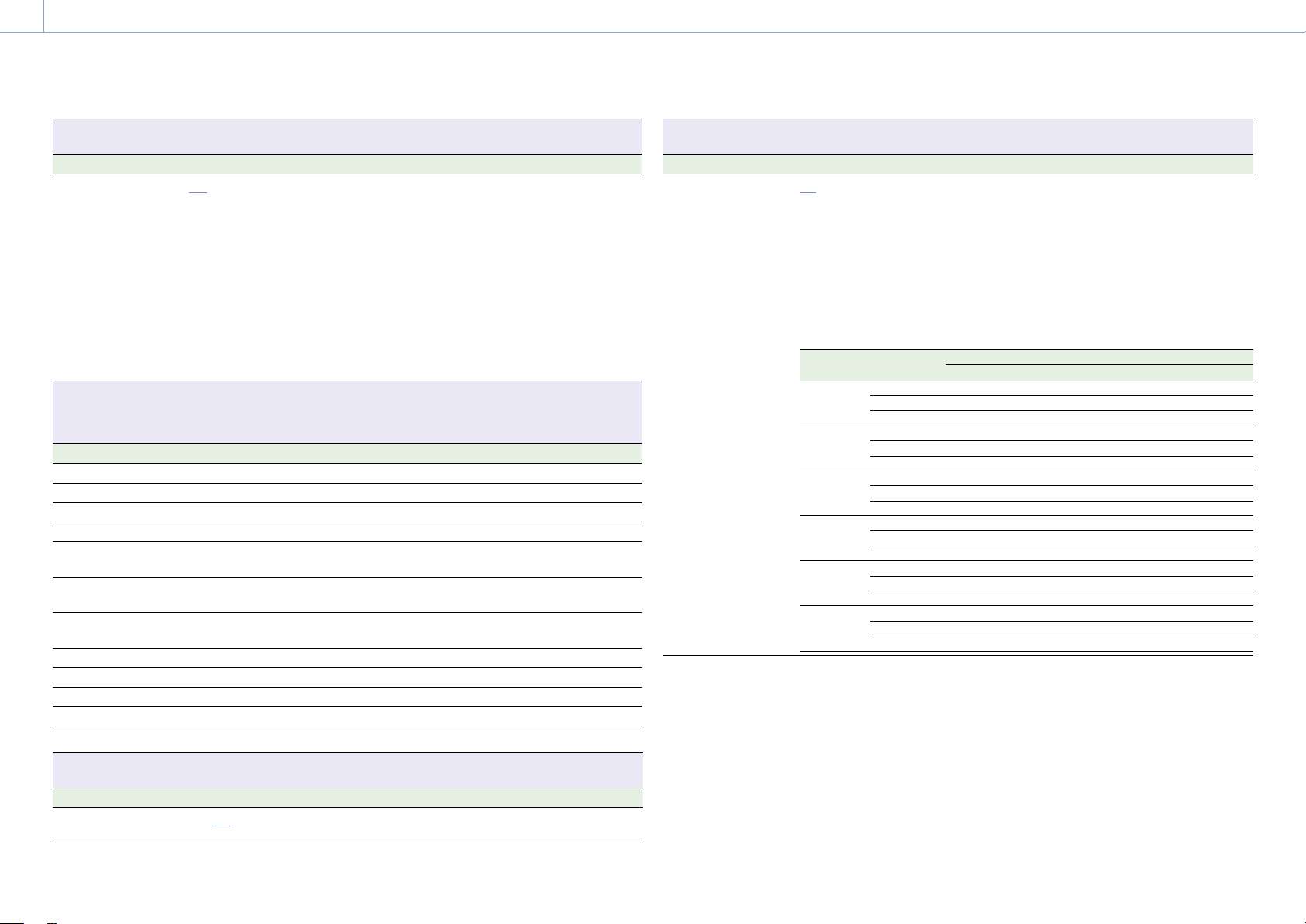
3. Camera Operations: Project Menu
73
Project > Basic Setting
Makes settings related to picture size and project frame rate.
Menu item Setting Description
Zoom to Fit
Off/17:9/16:9 You can set whether to cut out and magnify
the display of the recording image for the
viewfinder screen or Monitor output.
[Notes]
• Configurable under the following conditions.
Imager Mode: 8K 3:2/6K 3:2
Recording Format: X-OCN
Anamo. De-Squeeze: Off(1.0×)
• 16:9 cannot be selected when Project Frame Rate
is set to 47.95.
• If the setting is changed from 17:9 or 16:9 to
Off, the SDI output format returns to the default
setting.
Project > Assignable Button
Assigns functions to assignable buttons.
For details about assigning functions, see “User Functions Screen” (page 48).
Menu item Setting Description
<1> page 48 Assigns a function to assignable button 1.
<2> page 48 Assigns a function to assignable button 2.
<3> page 48 Assigns a function to assignable button 3.
<4> page 48 Assigns a function to assignable button 4.
<VF A> page 48 Assigns a function to assignable button A on
the viewfinder (DVF-EL200).
<VF B> page 48 Assigns a function to assignable button B on
the viewfinder (DVF-EL200).
<VF C> page 48 Assigns a function to assignable button C on
the viewfinder (DVF-EL200).
<User 1> page 48 Assigns a function to ITEM key 1.
<User 2> page 48 Assigns a function to ITEM key 2.
<User 3> page 48 Assigns a function to ITEM key 3.
<User 4> page 48 Assigns a function to ITEM key 4.
<User 5> page 48 Assigns a function to ITEM key 5.
Project > Special Recording
Makes settings related to picture cache recording.
Menu item Setting Description
Cache Rec Select
On/Off Turns the picture cache recording function
on/off.
Project > Special Recording
Makes settings related to picture cache recording.
Menu item Setting Description
Max Cache Rec
Duration
2 s/4 s/6 s/8 s/10 s/15 s/
24 s/30 s
Sets the playback duration of video to cache
in picture cache memory.
The maximum value that can be set for an
AXS memory card is given below.
[Note]
When FPS is set to Variable, the actual playback
duration will vary from the Max Cache Rec Duration
setting.
X-OCN recording
MPC-3628
Imager
Mode
Recording
Format
Project Frame Rate
23.98 24 25 29.97 47.95 50 59.94
8.6K 3:2 X-OCN XT 4 4 4 2 – – –
X-OCN ST 10 10 8 6 – – –
X-OCN LT 15 15 15 15 – – –
8.2K 17:9 X-OCN XT 8 8 8 6 – – –
X-OCN ST 15 15 15 10 4 4 2
X-OCN LT 30 30 30 24 10 10 8
7.6K 16:9 X-OCN XT 8 8 8 6 – – –
X-OCN ST 15 15 15 10 – 4 2
X-OCN LT 30 30 30 24 – 10 8
5.8K 6:5 X-OCN XT 10 10 10 8 2 – –
X-OCN ST 15 15 15 15 8 – –
X-OCN LT 30 30 30 30 15 – –
5.8K 17:9 X-OCN XT 24 24 24 15 8 8 6
X-OCN ST 30 30 30 30 15 15 10
X-OCN LT 30 30 30 30
30 30 24
5.4K 16:9 X-OCN XT 24 24 24 15 – 8 6
X-OCN ST 30 30 30 30 – 15 10
X-OCN LT 30 30 30 30 – 30 24
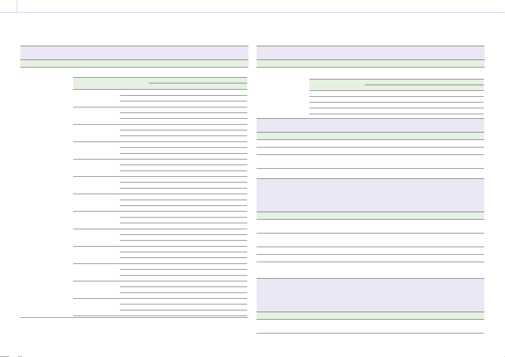
3. Camera Operations: Project Menu
74
Project > Special Recording
Makes settings related to picture cache recording.
Menu item Setting Description
MPC-3626
Imager Mode Recording
Format
Project Frame Rate
23.98 24 25 29.97 47.95 50 59.94
6K 3:2 X-OCN XT 15 15 15 10 4 4 2
X-OCN ST 24 24 24 15 10 10 6
X-OCN LT 30 30 30 30 15 15 15
6K 1.85:1 X-OCN XT 15 15 15 15 8 6 4
X-OCN ST 30 30 30 24 15 10 10
X-OCN LT 30 30 30 30 30 24 15
6K 17:9 X-OCN XT 15 15 15 15 8 8 4
X-OCN ST 30 30 30 24 15 10 10
X-OCN LT 30 30 30 30 30 24 15
6K 2.39:1 X-OCN XT 30 30 24 15 10 10 8
X-OCN ST 30 30 30 30 15 15 15
X-OCN LT 30 30 30 30 30 30 30
5.7K 16:9 X-OCN XT 15 15 15 15 – 8 4
X-OCN ST 30 30 30 24 – 10 10
X-OCN LT 30 30 30 30 –
24 15
4K 6:5 X-OCN XT 30 30 30 24 10 10 10
X-OCN ST 30 30 30 30 24 15 15
X-OCN LT 30 30 30 30 30 30 30
4K 4:3 X-OCN XT 30 30 30 30 15 15 10
X-OCN ST 30 30 30 30 24 24 15
X-OCN LT 30 30 30 30 30 30 30
4K 4:3 Surround X-OCN XT 30 30 30 30 – – –
X-OCN ST 30 30 30 30 – – –
X-OCN LT 30 30 30 30 – – –
4K 17:9 X-OCN XT 30 30 30 30 24 24 15
X-OCN ST 30 30 30 30 30 30 30
X-OCN LT 30 30 30 30 30 30 30
4K 17:9 Surround X-OCN XT 30 30 30 30 – – –
X-OCN ST 30 30 30 30 – – –
X-OCN LT 30 30 30 30 – – –
4K 2.39:1 X-OCN XT 30 30 30 30 30
30 24
X-OCN ST 30 30 30 30 30 30 30
X-OCN LT 30 30 30 30 30 30 30
3.8K(QFHD) 16:9 X-OCN XT 30 30 30 30 – 24 15
X-OCN ST 30 30 30 30 – 30 30
X-OCN LT 30 30 30 30 – 30 30
3.8K(QFHD) 16:9
Surround
X-OCN XT 30 30 30 30 – – –
X-OCN ST 30 30 30 30 – – –
X-OCN LT 30 30 30 30 – – –
Project > Special Recording
Makes settings related to picture cache recording.
Menu item Setting Description
ProRes recording
Recording Format Project Frame Rate
23.98 24 25 29.97 47.95 50 59.94
ProRes 4K 4444 30 30 30 30 – 15 10
ProRes 4K 422 HQ 30 30 30 30 – 24 15
ProRes QFHD 4444 30 30 30 30 – 15 10
ProRes QFHD 422 HQ 30 30 30 30 – 30 24
Project > All File(Cam Setup)
Makes settings related to All-settings files.
Menu item Setting Description
Load SD Card Load an All-settings file from an SD card.
Save SD Card Save an All-settings file on an SD card.
File ID Displays the file ID of the All-settings file for
editing.
Format SD Card Formats an SD card.
Project > Scene File
Makes settings related to scene files.
[Note]
Scene File can be displayed and selected only when Technical > Special Configuration > RM/RCP Paint Control
(page 91) is set to On in the full menu.
Menu item Setting Description
Recall Internal
Memory
Load a scene file from internal memory.
Store Internal
Memory
Save a scene file in internal memory.
Load SD Card Load a scene file from an SD card.
Save SD Card Save a scene file on an SD card.
File ID Displays the file ID of the scene file for
editing.
Project > User Gamma
Makes settings related to user gamma files.
[Note]
User Gamma can be displayed and selected only when Technical > Special Configuration > RM/RCP Paint Control
(page 91) is set to On in the full menu.
Menu item Setting Description
Current Settings Displays the name of the current user gamma
file in internal memory.
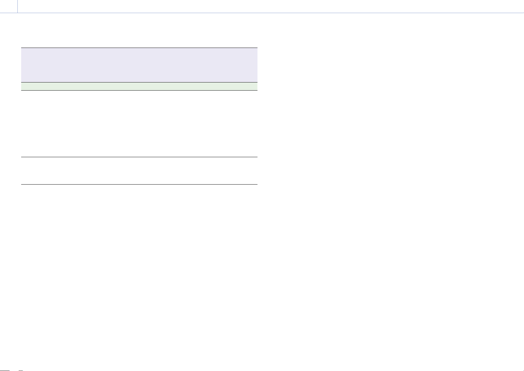
3. Camera Operations: Project Menu
75
Project > User Gamma
Makes settings related to user gamma files.
[Note]
User Gamma can be displayed and selected only when Technical > Special Configuration > RM/RCP Paint Control
(page 91) is set to On in the full menu.
Menu item Setting Description
Load SD Card Load user-defined gamma table data (user
gamma file) from an SD card to internal
memory.
Save user gamma files created using RAW
Viewer for use by the unit in the following
directory on the SD card.
MPC-3628:
PRIVATE\SONY\PRO\CAMERA\MPC3628
MPC-3626:
PRIVATE\SONY\PRO\CAMERA\MPC3626
Reset 1/2/3/4/5/All Reset the user gamma files in internal
memory to initial settings.
1 to 5: Reset individually
All: Reset all
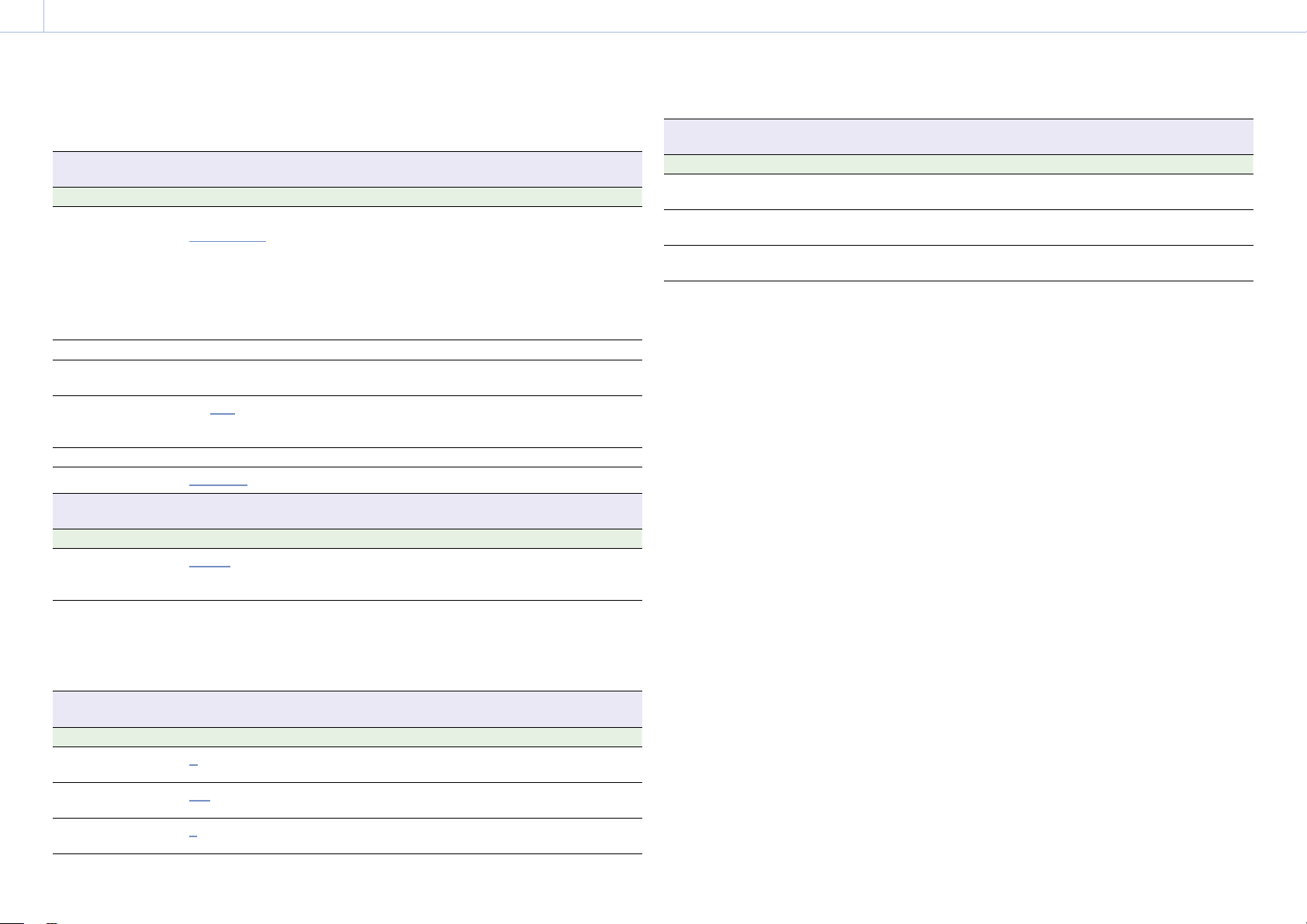
76
3. Camera Operations
TC/Media Menu
The functions and available settings of each menu item are given below.
Default values are shown underlined and in
bold text.
TC/Media > Timecode
Makes settings related to timecode.
Menu item Setting Description
Mode
Preset F-Run (Ext-Lk)/
Preset R-Run/Int Regen
Selects the timecode mode.
Preset F-Run (Ext-Lk): Timecode advances
continuously from specified value, in sync
with external input timecode.
Preset R-Run: Timecode advances from
specified value only when recording.
Int Regen: Timecode continues from that of
the previous clip.
Manual Setting 00:00:00:00 to 23:59:59:29 Sets an arbitrary timecode value.
Reset Run/Cancel Resets the timecode to 00:00:00:00 (execute
by selecting Run).
TC Format
DF/NDF Selects the timecode format.
DF: Drop frame
NDF: Non drop frame
TC Source Internal/External Displays the TCG sync source.
Time Data Display
Timecode/Duration Selects the time data to display.
TC/Media > Genlock
Makes settings related to genlock.
Menu item Setting Description
Input Source
HD SDI/Analog Selects the genlock input signal.
HD SDI: Digital
Analog: Analog
Reference Lock Type Internal/External(HD)/
External(SD)
Displays the genlock status. Displays the
signal type when genlocked.
Internal: Not genlocked.
External(HD): Genlocked by HD sync.
External(SD): Genlocked by SD sync.
TC/Media > Clip Name Format
Sets clip names. (Clip name: Camera ID + Reel Number + Shot Number + date + random string)
Menu item Setting Description
Camera ID
A to Z Sets the camera ID used when generating clip
names.
Reel Number
001 to 999 Sets the numeric portion of the Reel Number
used when generating clip names.
Camera Position
C/L/R Sets the first character portion of the Shot
Number used when generating clip names.
TC/Media > Format Media
Formats the media and updates the management file on the media.
Menu item Setting Description
AXS Slot A Run/Cancel Initializes the AXS memory card in slot A
(execute by selecting Run).
AXS Slot B Run/Cancel Initializes the AXS memory card in slot B
(execute by selecting Run).
SD Card Run/Cancel Initializes the SD card (execute by selecting
Run).
77
3. Camera Operations
Monitoring Menu
The functions and available settings of each menu item are given below.
Default values are shown underlined and in
bold text.
Monitoring > Output Format
Makes settings related to output format.
Menu item Setting Description
SDI 1/2 The available settings vary
according to the imager mode,
project frame rate, and
recording format settings.
Selects the SDI 1/2 output format.
Settings vary according to the recording
format (page 125).
SDI 3/4 The available settings vary
depending on the SDI 1/2
setting.
Selects the SDI 3/4 output format.
Settings vary according to the recording
format (page 125).
Monitor The available settings vary
depending on the SDI 1/2
setting.
Selects the Monitor output format.
Settings vary according to the recording
format (page 130).
HDMI The available settings vary
depending on the SDI 1/2
setting.
Selects the HDMI output format.
Settings vary according to the recording
format (page 130).
3G SDI 1/2/3/4
Output
Level A/Level B Selects whether the 3G SDI output format is
Level A or Level B.
Monitoring > Output Display
Makes settings related to monitor display.
Menu item Setting Description
Flip Image
Normal/Horizontal Flip/
Vertical Flip/H & V Flip
Sets the orientation of the shooting mode
image. When set to Normal, the image is not
flipped.
[Notes]
• AXS recording images are stored unflipped.
• When Vertical Flip or H & V Flip is selected, both
the video and audio signals are delayed by 1
frame at the imaging frame rate due to internal
processing.
Audio/Video Delay
Off/1frame Selects whether to enable the sync function
for synchronizing the audio and video with
another device that is flipping the image by
delaying the video signal and audio signal.
Off: No delay
1frame: Delay the video signal, audio signal,
and metadata (including the timecode) by
approximately 1 frame.
[Note]
Fixed to 1frame when Flip Image is set to Vertical Flip
or H & V Flip.
Monitoring > Output Display
Makes settings related to monitor display.
Menu item Setting Description
Monitor Magnifier
Mode
Toggle/Press & Hold Selects the method for turning the focus
magnifier function of the Monitor output
image on/off.
Toggle: Toggles the magnification on/off
each time you press an assignable button
assigned with Monitor Focus Magnifier.
Press & Hold: Turns the magnification on
while you press an assignable button
assigned with Monitor Focus Magnifier.
Monitor Magnifier
Ratio
×2.0 / ×4.0 / ×2.0/×4.0 Selects the focus magnification ratio for the
Monitor output image.
[Notes]
• Only ×2.0 can be selected when Project Frame
Rate (page 72) is set to 59.94 or 50.
• ×2.0/×4.0 cannot be selected when Monitor
Magnifier Mode is set to Press & Hold.
3. Camera Operations: Monitoring Menu
78
Monitoring > VF Display
Makes settings related to the viewfinder display.
Menu item Setting Description
VF LUT
[Note]
Linked to the Shooting
> LUT Select > VF LUT
(page 70) settings in
the full menu.
When Technical > Special
Configuration > RM/RCP Paint
Control (page 91) is set to
Off in the full menu:
Log/s709/R709(800%)/
Look
Selects the LUT to apply to the viewfinder/
monitor screen output image.
When RM/RCP Paint Control is
set to On:
The settings change as
follows depending on the
Project > Basic Setting >
Input Color Space
(page 72) setting in the
full menu.
S-Gamut3.Cine/SLog3 or
S-Gamut3/SLog3:
Log/
R709(800%)
HLG(Natural):
HLG(Natural)/
R709(800%)
HLG(Live):
HLG(Live)/
R709(800%)
Rec.2020/User Gamma:
User Gamma/
R709-Like
Rec.709/User Gamma:
User Gamma
Selects the type of viewfinder/monitor screen
output image.
[Notes]
• An SDR gain value (–12 dB) is applied to the
viewfinder/monitor output image.
• You can change the output gain using SDR Gain
when set to R709(800%) or R709-Like.
Overlay
Info. A/Info. B/Rec Ind./Off Selects the information to display
superimposed on the viewfinder/monitor
screen output image.
Frame Line
Frame Line A/Frame Line B/
Off
Selects the frame lines to display
superimposed on the viewfinder/monitor
screen output image.
VF Magnifier Mode
Toggle/Press & Hold Selects the method for turning the focus
magnifier function of the viewfinder on/off.
Toggle: Toggles the magnification on/off
each time you press an assignable button
assigned with VF Focus Magnifier.
Press & Hold: Turns the magnification on
while you press an assignable button
assigned with VF Focus Magnifier.
Monitoring > VF Display
Makes settings related to the viewfinder display.
Menu item Setting Description
VF Magnifier Ratio
×2.0 / ×4.0 / ×2.0/×4.0 Selects the focus magnification ratio for the
viewfinder.
[Note]
×2.0/×4.0 cannot be selected when VF Magnifier
Mode is set to Press & Hold.
Color
–99 to ±0 to +99 Adjusts the color depth of the viewfinder
image.
SDR Gain
–15dB to 0dB (–12dB)
(1dB increments)
Sets the SDR output gain when RM/RCP Paint
Control is set to On.
You can use this to change the gain of the
Monitor or viewfinder output that is set to
R709(800%) or R709-Like.
[Notes]
• Linked to the Shooting > LUT Select > SDR Gain
(page 71) settings in the full menu.
• Configurable when Technical > Special
Configuration > RM/RCP Paint Control
(page 91) is set to On in the full menu.
Monitoring > VF Function
Makes settings related to viewfinder functions.
Menu item Setting Description
Double Speed Scan
On/Off Turns the viewfinder double speed scan
function on/off.
Peaking Frequency
Normal/High Selects whether the peaking frequency is
normal or high during peaking.
[Note]
The peaking level is set using the viewfinder menu.
Assign<VF A> page 48 Assigns a function to assignable button A on
the viewfinder (DVF-EL200).
Assign<VF B> page 48 Assigns a function to assignable button B on
the viewfinder (DVF-EL200).
Assign<VF C> page 48 Assigns a function to assignable button C on
the viewfinder (DVF-EL200).
Zebra
On/Off Turns the zebra function on/off.
Zebra Select
1/2/Both Selects the zebra pattern type (Zebra 1, Zebra
2, Both).
Zebra1 Level
0% to 107% (41%) Sets the display level of zebra 1.
Zebra1 Aperture
Level
1% to 20% (10%) Sets the aperture level of zebra 1.
3. Camera Operations: Monitoring Menu
79
Monitoring > VF Function
Makes settings related to viewfinder functions.
Menu item Setting Description
Zebra2 Level
0% to 109% (61%) Sets the display level of zebra 2.
Monitoring > Overlays/Frame Line
Makes settings related to information and frame lines superimposed on each output signal.
On/Off setting is selected using a checkbox (excluding Frame Line on Playback).
On: Checkbox selected
Off: Checkbox cleared
Menu item Setting Description
VF
Overlay (On/Off,
Info. A/Info. B/Rec Ind.)
Selects the information to display
superimposed on the viewfinder/monitor
screen output image.
Frame Line (On/Off,
Line A/Line B)
Selects the frame lines to display
superimposed on the viewfinder/monitor
screen output image.
SDI 1/2
Overlay (On/Off,
Info. A/
Info. B/Rec Ind.)
Selects the information to display
superimposed on the SDI 1/2 output signal.
Frame Line (On/Off,
Line A/
Line B)
Selects the frame lines to display
superimposed on the SDI 1/2 output signal.
SDI 3/4
Overlay (On/Off,
Info. A/
Info. B/Rec Ind.)
Selects the information to display
superimposed on the SDI 3/4 output signal.
Frame Line (On/Off,
Line A/
Line B)
Selects the frame lines to display
superimposed on the SDI 3/4 output signal.
Same as Monitor Selects whether the information displayed
superimposed on the SDI 3/4 output signal is
the same as for the Monitor output.
Monitor
Overlay (On/Off,
Info. A/
Info. B/Rec Ind.)
Selects the information to display
superimposed on the Monitor output signal.
Frame Line (On/Off,
Line A/
Line B)
Selects the frame lines to display
superimposed on the Monitor output signal.
HDMI
Overlay (On/Off,
Info. A/Info. B/Rec Ind.)
Selects the information to display
superimposed on the HDMI output signal.
Frame Line (On/Off,
Line A/
Line B)
Selects the frame lines to display
superimposed on the HDMI output signal.
Same as SDI 1/2/3/4 / Same
as SDI 1/2 / Same as Monitor
Selects whether the information displayed
superimposed on the HDMI output signal is
the same as for the corresponding output.
Monitoring > Overlays/Frame Line
Makes settings related to information and frame lines superimposed on each output signal.
On/Off setting is selected using a checkbox (excluding Frame Line on Playback).
On: Checkbox selected
Off: Checkbox cleared
Menu item Setting Description
Overlay A/B Setup
Project
Info. A (
On/Off)
Info. B (
On/Off)
Selects whether to display the project
information in the output information set for
Overlay A and Overlay B.
Camera ID Status
Info. A (
On/Off)
Info. B (On/
Off)
Selects whether to display the camera ID
information in the output information set for
Overlay A and Overlay B.
TC/Genlock Status
Info. A (On/
Off)
Info. B (On/
Off)
Selects whether to display the timecode
external lock status and genlock status
information in the output information set for
Overlay A and Overlay B.
Timecode
Info. A (On/
Off)
Info. B (
On/Off)
Selects whether to display the timecode
information in the output information set for
Overlay A and Overlay B.
Audio Level Meter
Info. A (On/
Off)
Info. B (On/
Off)
Selects whether to display an audio level
meter in the output information set for
Overlay A and Overlay B.
Look Status
Info. A (On/
Off)
Info. B (On/
Off)
Selects whether to display the type of
selected Look in the output information set
for Overlay A and Overlay B.
Output LUT
Info. A (On/
Off)
Info. B (
On/Off)
Selects whether to display the output LUT
information in the output information set for
Overlay A and Overlay B.
Rec Format/LUT
Info. A (
On/Off)
Info. B (
On/Off)
Selects whether to display the recording
format and recording LUT information in the
output information set for Overlay A and
Overlay B.
VF Status
Info. A (
On/Off)
Info. B (On/
Off)
Selects whether to display the viewfinder
status information in the output information
set for Overlay A and Overlay B.
Roll/Tilt Value
Info. A (
On/Off)
Info. B (On/Off)
Selects whether to display the spirit level
information numerically in the output
information set for Overlay A and Overlay B.
[Note]
Roll/Tilt Value is grayed out and cannot be operated
when a CBK-3610XS is connected to the unit.
3. Camera Operations: Monitoring Menu
80
Monitoring > Overlays/Frame Line
Makes settings related to information and frame lines superimposed on each output signal.
On/Off setting is selected using a checkbox (excluding Frame Line on Playback).
On: Checkbox selected
Off: Checkbox cleared
Menu item Setting Description
Level Gauge
Info. A (
On/Off)
Info. B (On/
Off)
Selects whether to display the spirit level
information graphically in the output
information set for Overlay A and Overlay B.
[Note]
Level Gauge is grayed out and cannot be operated
when a CBK-3610XS is connected to the unit.
Lens Status
Info. A (
On/Off)
Info. B (
On/Off)
Option (Meter/
Feet)
Selects whether to display the lens
information in the output information set for
Overlay A and Overlay B.
Selects the focus position display units.
Remote Control Status
Info. A (
On/Off)
Info. B (On/
Off)
Selects whether to display the remote control
status information in the output information
set for Overlay A and Overlay B.
Monitoring > Overlays/Frame Line
Makes settings related to information and frame lines superimposed on each output signal.
On/Off setting is selected using a checkbox (excluding Frame Line on Playback).
On: Checkbox selected
Off: Checkbox cleared
Menu item Setting Description
Frame Line A/B
Setup
Color
Option (
White/Yellow/
Cyan/Green/Magenta/
Red/Blue)
Sets the display color of frame lines.
Center Marker
Line A (
On/Off)
Line B (
On/Off)
Option (
Cross/Open
Cross/Dot)
Selects whether to display the center marker
in the output information set for Frame Line A
and Frame Line B.
Selects the display form (Cross/Open Cross/
Dot) of the center marker.
Picture Area
Line A (
On/Off)
Line B (
On/Off)
Selects whether to display the picture area in
the output information set for Frame Line A
and Frame Line B.
Aspect Ratio
Line A (
On/Off)
Line B (
On/Off)
Option (17:9/
16:9/15:9/
14:9/13:9/9:16/4:3/1:1/
1.43:1/1.66:1/1.85:1/2:1/
2.35:1/2.39:1)
Selects whether to display the aspect ratio
marker in the output information set for
Frame Line A and Frame Line B.
Selects the mode (17:9/16:9/15:9/14:9/13:9/
9:16/4:3/1:1/1.43:1/1.66:1/1.85:1/2:1/2.35:1/
2.39:1) when displaying the aspect ratio
marker.
Aspect Ratio Type
Option (
Line/Mask/
Line&Mask)
Selects the display form of the aspect ratio
marker.
Line: Displays lines with color set by Color.
Mask: Displays a lower video signal level for
areas outside the marker area.
Line&Mask: Displays lines with color set by
Color and a lower video signal level for
areas outside the marker area.
Surround View Type
Option (
Line/Mask/
Line&Mask)
Selects the display form of the Surround View
marker.
Line: Displays the recording area using lines.
Mask: Displays the recording area by masking
(reducing) the video signal level outside
the recording area.
Line&Mask: Displays the recording area using
lines and by masking (reducing) the video
signal level outside the recording area.
Mask Level
Option (0 to 15 (12))
Selects the brightness of the image outside
the marker when Aspect Ratio Type or
Surround View Type is set to Mask.
3. Camera Operations: Monitoring Menu
81
Monitoring > Overlays/Frame Line
Makes settings related to information and frame lines superimposed on each output signal.
On/Off setting is selected using a checkbox (excluding Frame Line on Playback).
On: Checkbox selected
Off: Checkbox cleared
Menu item Setting Description
Safety Zone
Line A (On/
Off)
Line B (On/
Off)
Option
(80%/
90%/92.5%/95%)
Selects whether to display the safety zone in
the output information set for Frame Line A
and Frame Line B.
Selects the range (80%/90%/92.5%/95%) of
the safety zone.
Aspect Safety Zone
Line A (On/
Off)
Line B (On/
Off)
Option
(80%/
90%/92.5%/95%)
Selects whether to display the aspect safety
zone in the output information set for Frame
Line A and Frame Line B.
Selects the size (percentage of the entire
screen) of the aspect safety zone marker.
User Frame Line 1
Line A (On/
Off)
Line B (On/
Off)
Option
(Preset/
Variable)
Selects whether to display user frame line 1 in
the output information set for Frame Line A
and Frame Line B.
Selects whether to display user frame line 1 or
fixed aspect ratio.
User Frame Line 2
Line A (On/
Off)
Line B (On/
Off)
Option
(Preset/
Variable)
Selects whether to display user frame line 2 in
the output information set for Frame Line A
and Frame Line B.
Selects whether to display user frame line 2 or
fixed aspect ratio.
Frame Line on Playback
Option (
On/Off)
Turns the function to superimpose frame lines
during playback on/off.
Monitoring > Frame Line Setup
Makes settings related to lines and markers displayed on the output image.
Menu item Setting Description
Color
White/Yellow/Cyan/Green/
Magenta/Red/Blue
Selects the display color of frame lines.
Center Marker
Cross/Open Cross/Dot Selects the display form of the center marker.
Aspect Ratio
17:9/16:9/15:9/14:9/13:9/
9:16/4:3/1:1/1.43:1/1.66:1/
1.85:1/2:1/2.35:1/2.39:1
Selects the mode when displaying the aspect
ratio marker.
Monitoring > Frame Line Setup
Makes settings related to lines and markers displayed on the output image.
Menu item Setting Description
Aspect Ratio Type
Line/Mask/Line&Mask Selects the display form of the aspect ratio
marker.
Line: Displays lines with color set by Color.
Mask: Displays a lower video signal level for
areas outside the marker area.
Line&Mask: Displays lines with color set by
Color and a lower video signal level for
areas outside the marker area.
Surround View Type
Line/Mask/Line&Mask Selects the display form of the Surround View
marker.
Line: Displays the recording area using lines.
Mask: Displays the recording area by masking
(reducing) the video signal level outside
the recording area.
Line&Mask: Displays the recording area using
lines and by masking (reducing) the video
signal level outside the recording area.
Mask Level
0 to 15 (12) Selects the brightness of the image outside
the marker when Aspect Ratio Type or
Surround View Type is set to Mask.
Safety Zone
80%/90%/92.5%/95% Selects the safety zone range.
Aspect Safety Zone
80%/90%/92.5%/95% Selects the size (percentage of the entire
screen) of the aspect safety zone marker.
Frame Line on
Playback
On/Off Turns the function to superimpose frame lines
during playback on/off.
Monitoring > User Frame Line 1
Makes settings related to user frame line 1.
Menu item Setting Description
Select
Preset/Variable Selects whether to display user frame line 1 or
fixed aspect ratio.
Preset: Displays the aspect ratio set by Preset
Aspect Ratio, Scaling, and Preset Aspect
Ratio Type.
Variable: Displays an arbitrary rectangular
frame set by Width, Height, H Position, V
Position, and Variable Aspect Type.

3. Camera Operations: Monitoring Menu
82
Monitoring > User Frame Line 1
Makes settings related to user frame line 1.
Menu item Setting Description
Preset Aspect Ratio
17:9/16:9/15:9/14:9/13:9/
9:16/4:3/1:1/1.43:1/1.66:1/
1.85:1/2:1/2.35:1/2.39:1/
1.90:1 (W34)*
* Frame line with the same
horizontal picture size as when
1.43:1 is set. In 6K 3:2 mode,
the horizontal picture size is
approximately 34 mm.
Selects the mode when displaying a fixed
aspect ratio.
[Note]
Configurable only when Select is set to Preset.
Scaling
1% to 100%/--- Sets the scale factor for a fixed aspect ratio.
[Notes]
• Configurable only when Select is set to Preset.
• “---” is displayed when Preset Aspect Ratio is set
to 1.90:1 (W34), and configuration is not possible.
Preset Aspect Ratio
Type
Line/Mask/Line&Mask Selects the display form for a fixed aspect
ratio.
Line: Displays using lines.
Mask: Displays a lower video signal level for
areas outside the marker area.
Line&Mask: Displays lines and a lower video
signal level for areas outside the marker
area.
[Note]
Configurable only when Select is set to Preset.
Aspect Ratio(Pixels) Aspect ratio (number of pixels,
anamorphic ratio)
Displays the aspect ratio of user frame line 1,
number of pixels, and anamorphic ratio for
the effective picture size.
[Note]
The number of pixels is the value for the effective
picture size before anamorphic de-squeeze
conversion.
Width
3 to 480 (240) Sets the user frame line 1 width (distance from
the center to the left and right edges).
[Note]
Configurable only when Select is set to Variable.
Height
3 to 270 (135) Sets the user frame line 1 height (distance
from the center to the top and bottom edges).
[Note]
Configurable only when Select is set to Variable.
Monitoring > User Frame Line 1
Makes settings related to user frame line 1.
Menu item Setting Description
H Position
Max. –477 to 477 (±0) Sets the horizontal position of the center of
user frame line 1.
The setting range becomes narrower as the
Width setting increases above 3.
[Note]
Configurable only when Select is set to Variable.
V Position Max. –267 to 267 (±0) Sets the vertical position of the center of user
frame line 1.
The setting range becomes narrower as the
Height setting increases above 3.
[Note]
Configurable only when Select is set to Variable.
Variable Aspect Type Line Displays the type of the user frame line 1
display.
[Note]
Displayed only when Select is set to Variable.
Monitoring > User Frame Line 2
Makes settings related to user frame line 2.
Menu item Setting Description
Select
Preset/Variable Selects whether to display user frame line 2 or
fixed aspect ratio.
Preset: Displays the aspect ratio set by Preset
Aspect Ratio, Scaling, and Preset Aspect
Ratio Type.
Variable: Displays an arbitrary rectangular
frame set by Width, Height, H Position, V
Position, and Variable Aspect Type.
Preset Aspect Ratio
17:9/16:9/15:9/14:9/13:9/
9:16/4:3/1:1/1.43:1/1.66:1/
1.85:1/2:1/2.35:1/2.39:1/
1.90:1 (W34)*
* Frame line with the same
horizontal picture size as when
1.43:1 is set. In 6K 3:2 mode,
the horizontal picture size is
approximately 34 mm.
Selects the mode when displaying a fixed
aspect ratio.
[Note]
Configurable only when Select is set to Preset.
3. Camera Operations: Monitoring Menu
83
Monitoring > User Frame Line 2
Makes settings related to user frame line 2.
Menu item Setting Description
Scaling
1% to 100%/--- Sets the scale factor for a fixed aspect ratio.
[Notes]
• Configurable only when Select is set to Preset.
• “---” is displayed when Preset Aspect Ratio is set
to 1.90:1 (W34), and configuration is not possible.
Preset Aspect Ratio
Type
Line Displays the display form for a fixed aspect
ratio.
[Note]
Displayed only when Select is set to Preset.
Aspect Ratio(Pixels) Aspect ratio (number of pixels,
anamorphic ratio)
Displays the aspect ratio of user frame line 2,
number of pixels, and anamorphic ratio for
the effective picture size.
[Note]
The number of pixels is the value for the effective
picture size before anamorphic de-squeeze
conversion.
Width 3 to 480 (240) Sets the user frame line 2 width (distance
from the center to the left and right edges).
[Note]
Configurable only when Select is set to Variable.
Height 3 to 270 (135) Sets the user frame line 2 height (distance
from the center to the top and bottom edges).
[Note]
Configurable only when Select is set to Variable.
H Position Max. –477 to 477 (±0) Sets the horizontal position of the center of
user frame line 2.
The setting range becomes narrower as the
Width setting increases above 3.
[Note]
Configurable only when Select is set to Variable.
V Position Max. –267 to 267 (±0) Sets the vertical position of the center of user
frame line 2.
The setting range becomes narrower as the
Height setting increases above 3.
[Note]
Configurable only when Select is set to Variable.
Monitoring > User Frame Line 2
Makes settings related to user frame line 2.
Menu item Setting Description
Variable Aspect Type Line Displays the type of the user frame line 2
display.
[Note]
Displayed only when Select is set to Variable.
84
3. Camera Operations
Audio Menu
The functions and available settings of each menu item are given below.
Default values are shown underlined and in
bold text.
Audio > Audio Input
Makes settings related to audio recording levels.
[Note]
The audio recording level with AES/EBU signal selected is fixed.
Menu item Setting Description
Internal Mic Select
Off / CH-1/CH-2 / CH-3/CH-4 Selects the input channel of the internal
microphone.
XLR Audio L Select
Auto/Manual Automatically adjusts the audio recording
when set to Auto.
XLR Audio R Select
Auto/Manual Automatically adjusts the audio recording
when set to Auto.
XLR Audio L Level
–99 to ±0 to +99 Adjusts the audio recording level when CH-1
Audio Select is set to Manual.
XLR Audio R Level
–99 to ±0 to +99 Adjusts the audio recording level when CH-2
Audio Select is set to Manual.
XLR Mic Reference
–60dB/–50dB/–40dB Selects the reference input level of the
microphone.
Audio > Audio Monitor
Makes settings related to audio monitoring.
Menu item Setting Description
Monitor CH
When Monitor Output CH Pair
is set to CH-1/CH-2
CH-1/CH-2, CH-1, CH-2
When Monitor Output CH Pair
is set to CH-3/CH-4
CH-3/CH-4, CH-3, CH-4
Selects the audio channel that is output to the
headphones and speaker.
CH-1/CH-2 (CH-3/CH-4): Channel 1+2 (Channel
3+4)
CH-1 (CH-3): Channel 1 (Channel 3) only
CH-2 (CH-4): Channel 2 (Channel 4) only
Monitor Level
0 to 99 Adjusts the monitor audio level.
[Note]
If configured such that the internal microphone
captured sound is audible from the built-in speaker,
howling may occur if the monitor volume is
increased.
Audio > Audio Configuration
Makes settings related to audio input/output.
Menu item Setting Description
Alarm Level
0 to 99 Adjusts the alarm audio level.
Input Limiter Mode
Off/–6dB/–9dB/–12dB/
–15dB/–17dB
Selects the limiter characteristic (saturation
level) for large input signals when adjusting
the audio input level manually. Select Off if
not using the limiter.
Audio > Audio Configuration
Makes settings related to audio input/output.
Menu item Setting Description
AGC Level
–6dB/–9dB/–12dB/
–15dB/–17dB
Selects the AGC characteristic (saturation
level).
AGC Mono/Stereo
Mono/Stereo Automatically adjusts the input level of
analog audio signals recorded on channels 1
and 2, and selects whether to make the
adjustments separately for each channel
(Mono) or in stereo mode (Stereo).
MIC Input Mono/
Stereo
Mono/Stereo Selects whether the front microphone is
monaural (Mono) or stereo (Stereo).
Phantom Power
+48V
On/Off Turns the function to supply a +48 V external
source (phantom power) to the microphone
on/off.
Monitor Output CH
Pair
CH-1/CH-2, CH-3/CH-4 Sets the audio output channels to either
channels 1 and 2 or channels 3 and 4.
Headphone Mono/ST
Mono/Stereo Sets the headphones output to monaural
(Mono) or stereo (Stereo).

85
3. Camera Operations
Paint Menu
The functions and available settings of each menu item are given below.
[Note]
Technical > Special Configuration > RM/RCP Paint Control (page 91) must be set to On in the full menu to enable
the setting of Paint menu items.
Default values are shown underlined and in
bold text.
Paint > Black
Makes settings related to black level.
Menu item Setting Description
Master Black
–99 to ±0 to +99 Sets the master black level.
R Black
–99 to ±0 to +99 Sets the R black level.
B Black
–99 to ±0 to +99 Sets the B black level.
Paint > Flare
Makes settings related to flare correction.
Menu item Setting Description
Setting
On/Off Turns the flare correction function on/off.
Master Flare
–99 to ±0 to +99 Sets the master flare user adjustment of the
flare correction required by the unit.
R Flare
–99 to ±0 to +99 Sets the R flare user adjustment of the flare
correction required by the unit.
G Flare
–99 to ±0 to +99 Sets the G flare user adjustment of the flare
correction required by the unit.
B Flare
–99 to ±0 to +99 Sets the B flare user adjustment of the flare
correction required by the unit.
Paint > Gamma
Makes settings related to gamma correction.
Menu item Setting Description
Setting
On/Off Turns the gamma correction function on/off.
Gamma Category S-Log3/HLG(Natural)/
HLG(Live)/User
The gamma category setting is display only,
because it is determined by the Project >
Basic Setting > Input Color Space (page 72)
setting in the full menu.
Paint > Gamma
Makes settings related to gamma correction.
Menu item Setting Description
Gamma Select
When Gamma Category is set
to S-Log3:
S-Log3
When Gamma Category is set
to HLG(Natural):
HLG(Natural)
When Gamma Category is set
to HLG(Live):
HLG(Live)
When Gamma Category is set
to User:
User 1/User 2/User 3/
User 4/User 5
Selects the gamma table used for gamma
correction.
Paint > Black Gamma
Makes settings related to black gamma correction.
[Note]
Black Gamma is grayed out and cannot be operated when Project > Basic Setting > Input Color Space (page 72) is
set to S-Gamut3.Cine/SLog3 or S-Gamut3/SLog3 in the full menu.
Menu item Setting Description
Setting
On/Off Turns the black gamma correction function
on/off.
Range
Low/L.Mid/H.Mid Selects the effective range of black gamma
correction.
Low: 0% to 3.6%
L.Mid: 0% to 7.2%
H.Mid: 0% to 14.4%
Master Black Gamma
–99 to ±0 to +99 Sets the master black gamma level.
Paint > Knee
Makes settings related to knee correction.
[Note]
Knee is grayed out and cannot be operated when Project > Basic Setting > Input Color Space (page 72) is set to
S-Gamut3.Cine/SLog3 or S-Gamut3/SLog3 in the full menu.
Menu item Setting Description
Setting
On/Off Turns the knee correction function on/off.
Point
–99 to ±0 to +99 Sets the knee point.
Slope
–99 to ±0 to +99 Sets the knee slope.
3. Camera Operations: Paint Menu
86
Paint > White Clip
Makes settings related to white clip adjustment.
[Note]
White Clip is grayed out and cannot be operated when Project > Basic Setting > Input Color Space (page 72) is set
to S-Gamut3.Cine/SLog3 or S-Gamut3/SLog3 in the full menu.
Menu item Setting Description
Setting
On/Off Turns the white clip adjustment function on/
off.
Level
60.0% to 108.0% to 109.0% Sets the white clip level.
Paint > Detail
Makes settings related to detail adjustment.
Menu item Setting Description
Setting
On/Off Turns the detail adjustment function on/off.
Level
–99 to ±0 to +99 Sets the detail level.
H/V Ratio
–99 to ±0 to +99 Sets the mix ratio of the H detail level and V
detail level.
Crispening
–99 to ±0 to +99 Sets the crispening level.
Level Depend
On/Off Turns the level dependence adjustment
function on/off.
Level Depend Level
–99 to ±0 to +99 Sets the level dependence level.
Frequency
–99 to ±0 to +99 Sets the center frequency of the H detail
signal (larger values give finer detail).
Knee Aperture
On/Off Turns the knee aperture correction function
on/off.
Knee Aperture Level
–99 to ±0 to +99 Sets the knee aperture level.
Limit
–99 to ±0 to +99 Sets the detail limiter for both the white side
and black side.
White Limit
–99 to ±0 to +99 Sets the detail limiter for the white side.
Black Limit
–99 to ±0 to +99 Sets the detail limiter for the black side.
Paint > Matrix
Makes settings related to matrix correction.
Menu item Setting Description
Setting
On/Off Turns the matrix correction function on/off.
User Matrix
On/Off Turns the user matrix correction function on/
off.
User Matrix R-G
–99 to ±0 to +99 Sets matrix coefficients individually for fine
adjustment of the color of the whole image.
User Matrix R-B
–99 to ±0 to +99
User Matrix G-R
–99 to ±0 to +99
User Matrix G-B
–99 to ±0 to +99
User Matrix B-R
–99 to ±0 to +99
User Matrix B-G
–99 to ±0 to +99
Paint > Multi Matrix
Makes settings related to multi matrix correction.
[Note]
Multi Matrix is grayed out and cannot be operated when Matrix is set to Off.
Menu item Setting Description
Setting
On/Off Turns multi-matrix correction function on/off
for setting the saturation in 16-axis hue space.
Area Indication
On/Off Turns the display of a zebra pattern in the
color area of the screen targeted for multi
matrix correction on/off.
Reset Run/Cancel Sets all [Hue] and [Saturation] values on each
axis to default values (execute by selecting
Run).
Axis
B/B+/MG–/MG/MG+/R/R+/
YL–/YL/YL+/G–/G/G+/CY/
CY+/B–
Sets the color targeted for multi matrix
correction (16-axis mode)
Hue
–99 to ±0 to +99 Sets the hue of the color targeted for multi
matrix correction for each of the 16 axes.
Saturation
–99 to ±0 to +99 Sets the saturation of the color targeted for
multi matrix correction for each of the 16 axes.
87
3. Camera Operations
Technical Menu
The functions and available settings of each menu item are given below.
Default values are shown underlined and in
bold text.
Technical > System Configuration
Makes settings related to control of the unit.
Menu item Setting Description
Fan Control
Auto / Max /
Off in Rec/Auto /
Off in Rec/Max
Selects the fan control mode.
Auto: Controls the fan automatically in
response to the internal temperature.
Max: Fan rotates at maximum speed.
Off in Rec/Auto: The fan is silent when
recording, and operates automatically in
response to the internal temperature
when not recording.
Off in Rec/Max: The fan is silent when
recording, and rotates at maximum speed
when not recording.
Shutter Mode
Speed/Angle Selects the operating mode of the electronic
shutter.
SDI Rec Remote
Trigger
Off / HD SDI Remote I/F /
Parallel Rec
Selects the SDI remote mode control method.
Off: Disables remote control.
HD SDI Remote I/F: Uses HD SDI Remote
control method.
Parallel Rec: Uses valid flag control method.
Level Gauge Adjust Run/Cancel Execute the zero adjustment of the spirit level
gauge (execute by selecting Run).
Level Gauge Reset Run/Cancel Reset the zero adjustment value of the spirit
level gauge (execute by selecting Run).
Technical > Lens Configuration
Makes settings related to lenses.
Menu item Setting Description
PL-Mt Interface
Position
Top/Side/Off Sets the interface position of the PL-mount
lens.
[Note]
Set before attaching a lens, according to the lens
to attach. If changing this setting while the lens is
attached to the unit, reboot the unit.
PL-Mt Voltage
8 V 24 V/24 V
Sets the powering method of the PL-mount lens.
Focus Distance
Format
Meter/Feet
Selects the focus position display units.
Lens 12pin On/Off Turns the 12-pin lens interface on/off.
[Note]
If changing this setting while the lens is attached to
the unit, reboot the unit.
Technical > Lens Configuration
Makes settings related to lenses.
Menu item Setting Description
E-Mount Shading
Comp.
Auto/Off Sets whether to compensate for a drop in
peripheral lighting when a compatible lens is
attached.
E-Mt Chro. Aber.
Comp.
Auto/Off Sets whether to compensate for chromatic
aberration in peripheral lighting when a
compatible lens is attached.
Technical > Auto Pixel Restore
Executes Auto Pixel Restoration (auto adjustment of the image sensor).
Menu item Setting Description
Auto Pixel
Restoration
Run/Cancel Executes the automatic pixel noise reduction
function (execute by selecting Run).
Reset Run/Cancel Deletes white flecks added by execution of
the APR function (execute by selecting Run).
Technical > Authentication
Makes basic settings related to network authentication.
Menu item Setting Description
User Name (Displays the current user
name.)
Sets the user name to use for access
authentication.
Set to “admin” by factory default.
Password (*******) Sets the password to use for access
authentication (8 or more alphanumeric
characters containing at least one alphabetic
and one numeric character).
When entering a password, the asterisk
characters displayed are replaced by the
entered characters while the sub display ITEM
key 1 is pressed.
Technical > Network
Makes settings related to the network.
Menu item Setting Description
Setting
LAN/Wireless/Off Sets the network connection method.
[Note]
Grayed out and cannot be changed if a password is
not configured using Technical > Authentication >
Password (page 87) in the full menu.
3. Camera Operations: Technical Menu
88
Technical > Network
Makes settings related to the network.
Menu item Setting Description
LAN
DHCP (On/Off) Sets DHCP.
When set to On, an IP address is automatically
assigned to the unit. To enter the IP address
of the unit manually, set to Off.
IP Address (DHCP/On: obtain
automatically
, DHCP/Off:
192.168.2.50)
Enter the IP address of the unit.
Enabled when DHCP is set to Off.
Subnet Mask (DHCP/On:
obtain automatically, DHCP/
Off:
255.255.255.0)
Enter the subnet mask of the unit.
Enabled when DHCP is set to Off.
Wireless
Network Mode (Access Point/
Station)
Sets the network mode for wireless
connections.
Scan Networks (Run/Cancel) Scans for access points for connection
destinations (execute by selecting Run).
[Note]
Configurable only when Network Mode is set to
Station.
SSID When Network Mode is set to Access Point
Displays the SSID for the wireless
connection to the unit.
When Network Mode is set to Station
Displays/configures the SSID of the
connection destination access point.
[Note]
Valid characters for display and entry:
Alphabetic (A to Z, a to z)
Numeric (0 to 9 -.@—_())
Symbols (!"#$%&'*+,/:;<=>?[\]^`{|}~)
Technical > Network
Makes settings related to the network.
Menu item Setting Description
Password When Network Mode is set to Access Point
Displays the password for wireless
connection to the unit.
When Network Mode is set to Station
Configures the password of the
connection destination access point.
When entering a password, the asterisk
characters displayed are replaced by the
entered characters while the sub display
ITEM key 1 is pressed.
[Note]
Valid characters for display and entry:
Alphabetic (A to Z, a to z)
Numeric (0 to 9 -.@—_())
Symbols (!"#$%&'*+,/:;<=>?[\]^`{|}~)
WPS (Run/Cancel) Starts connection setup using WPS (execute
by selecting Run).
Channel (Auto(5GHz)/Auto/
CH1/CH2/CH3/CH4/CH5/CH6/
CH7/CH8/CH9/CH10/CH11)
Sets the channel of the access point.
[Notes]
• Configurable only when Network Mode is set to
Access Point.
• Auto(5GHz) may not be displayed, depending
on the wireless LAN module being used. Check
whether use of the wireless LAN module is
supported in your country/region. For details,
refer to the operating instructions of the wireless
LAN module.
DHCP (On/Off) Sets DHCP.
When set to On, an IP address is automatically
assigned to the unit. To enter the IP address
of the unit manually, set to Off.
[Note]
Configurable only when Network Mode is set to
Station.
IP Address (DHCP/On: obtain
automatically
, DHCP/Off:
192.168.1.50)
Enter the IP address of the unit.
Enabled when DHCP is set to Off.
[Note]
Configurable only when Network Mode is set to
Station.
3. Camera Operations: Technical Menu
89
Technical > Network
Makes settings related to the network.
Menu item Setting Description
Subnet Mask (DHCP/On:
obtain automatically, DHCP/
Off:
255.255.255.0)
Enter the subnet mask of the unit.
Enabled when DHCP is set to Off.
[Note]
Configurable only when Network Mode is set to
Station.
MAC Address Displays the MAC address of the wireless LAN
adaptor connected to the unit.
Regenerate Password (Run/
Cancel)
Regenerates the password (execute by
selecting Run).
[Note]
Executable only when Network Mode is set to Access
Point.
Technical > Alerts & Tally
Makes settings related to the REC button and media capacity alerts.
Menu item Setting Description
Rec Light
On/Off Turns the REC lamp on/off.
Rec Start/Stop Beep
0 to 99 Adjusts the volume of the beep sound
emitted when recording starts and stops.
Media Near Full
Alarm
1min/3min/5min Sets the alarm threshold for notification that
the remaining media is low.
Technical > Batt./Voltage Alarm
Makes settings related to batteries and external DC power supply voltage alarms.
Menu item Setting Description
Near End:Info Battery
5% to 100% (5% increments) Sets the threshold value at which the
remaining battery capacity indicator starts
flashing when using a Sony Info battery.
End:Info Battery
0% to 5% Sets the threshold value for displaying the
“Battery End” warning when using a Sony Info
battery.
Near End:Sony
Battery
11.5V to 17V (0.1V increments) Sets the threshold value at which the
remaining battery capacity indicator starts
flashing when using a Sony non-Info battery.
End:Sony Battery
11.0V to 12.5V (0.1V
increments)
Sets the threshold value for displaying the
“Battery End” warning when using a Sony
non-Info battery.
Near End:Other
Battery
11.5V to 17V (11.8V) (0.1V
increments)
Sets the threshold value at which the
remaining battery capacity indicator starts
flashing when using a non-Sony battery.
Technical > Batt./Voltage Alarm
Makes settings related to batteries and external DC power supply voltage alarms.
Menu item Setting Description
End:Other Battery
11.0V to 14V (0.1V increments) Sets the threshold value for displaying the
“Battery End” warning when using a non-Sony
battery.
Detected Battery Sony Info Battery/Sony
Battery/Other Battery/DC IN
(12V)/DC IN (24V)
Displays the result of automatic battery pack
type detection.
DC Low Voltage1 11.5V to 17V (0.1V increments) Sets the threshold value for displaying a low
voltage warning when using an external
power source connected to the DC IN
connector.
DC Low Voltage2
11.0V to 14V (0.1V increments) Sets the threshold value for displaying an
undervoltage warning when using an external
power source connected to the DC IN
connector.
DC(24V) Low
Voltage1
22.5V to 34.0V (0.1V
increments)
Sets the threshold value for displaying a low
voltage warning when using a 24 V external
power source connected to the DC IN
connector.
DC(24V) Low
Voltage2
22.0V to 28.0V (0.1V
increments)
Sets the threshold value for displaying an
undervoltage warning when using a 24 V
external power source connected to the DC IN
connector.
Technical > Panel Control
Makes settings related to the displays.
Menu item Setting Description
Brightness level
High/Mid/Low/Minimum Adjusts the brightness of the sub display and
mini display.
Lock Operator Side
without Rec Button /
without Assign3 Button /
without Rec/Assign3 /
with Rec/Assign3 Button
Sets whether to lock the REC button or
Assign3 button operation when buttons are
locked using the LOCK switch on the Operator
side.
Lock Assistant Side
without Rec Button /
with Rec Button
Sets whether to lock the REC button operation
when buttons are locked using the LOCK
switch on the Assistant side.
3. Camera Operations: Technical Menu
90
Technical > False Color
Makes settings related to false colors.
[Note]
False Color is grayed out and the setting cannot be changed when Technical > Special Configuration > RM/RCP Paint
Control (page 91) is set to On in the full menu.
Menu item Setting Description
Level
Preset/Manual Sets whether to use the preset on/off setting
and threshold of each false color in the
viewfinder/monitor output or to set colors
manually.
When Manual is selected, the following items
can be configured.
Red
On/Off Turns the display of red on/off.
Red Upper Limit
0.0% to 109.0% (96.1%)
(0.1% increments)
Sets the upper limit for display in red.
Red Lower Limit
0.0% to 109.0% (93.4%)
(0.1% increments)
Sets the lower limit for display in red.
Yellow
On/Off Turns the display of yellow on/off.
Yellow Upper Limit
0.0% to 109.0% (93.4%)
(0.1% increments)
Sets the upper limit for display in yellow.
Yellow Lower Limit
0.0% to 109.0% (91.3%)
(0.1% increments)
Sets the lower limit for display in yellow.
Orange
On/Off Turns the display of orange on/off.
Orange Upper Limit
0.0% to 109.0% (90.6%)
(0.1% increments)
Sets the upper limit for display in orange.
Orange Lower Limit
0.0% to 109.0% (87.7%)
(0.1% increments)
Sets the lower limit for display in orange.
Pink
On/Off Turns the display of pink on/off.
Pink Upper Limit
0.0% to 109.0% (58.0%)
(0.1% increments)
Sets the upper limit for display in pink.
Pink Lower Limit
0.0% to 109.0% (54.3%)
(0.1% increments)
Sets the lower limit for display in pink.
Light Pink
On/Off Turns the display of light pink on/off.
Light Pink Upper
Limit
0.0% to 109.0% (50.8%)
(0.1% increments)
Sets the upper limit for display in light pink.
Light Pink Lower
Limit
0.0% to 109.0% (47.8%)
(0.1% increments)
Sets the lower limit for display in light pink.
Cyan
On/Off Turns the display of cyan on/off.
Cyan Upper Limit
0.0% to 109.0% (46.5%)
(0.1% increments)
Sets the upper limit for display in cyan.
Cyan Lower Limit
0.0% to 109.0% (43.8%)
(0.1% increments)
Sets the lower limit for display in cyan.
Technical > False Color
Makes settings related to false colors.
[Note]
False Color is grayed out and the setting cannot be changed when Technical > Special Configuration > RM/RCP Paint
Control (page 91) is set to On in the full menu.
Menu item Setting Description
Green
On/Off Turns the display of green on/off.
Green Upper Limit
0.0% to 109.0% (42.2%)
(0.1% increments)
Sets the upper limit for display in green.
Green Lower Limit
0.0% to 109.0% (38.9%)
(0.1% increments)
Sets the lower limit for display in green.
Light Blue
On/Off Turns the display of light blue on/off.
Light Blue Upper
Limit
0.0% to 109.0% (34.4%)
(0.1% increments)
Sets the upper limit for display in light blue.
Light Blue Lower
Limit
0.0% to 109.0% (24.6%)
(0.1% increments)
Sets the lower limit for display in light blue.
Blue
On/Off Turns the display of blue on/off.
Blue Upper Limit
0.0% to 109.0% (5.6%)
(0.1% increments)
Sets the upper limit for display in blue.
Blue Lower Limit
0.0% to 109.0% (3.5%)
(0.1% increments)
Sets the lower limit for display in blue.
Purple
On/Off Turns the display of purple on/off.
Purple Upper Limit
0.0% to 109.0% (3.5%)
(0.1% increments)
Sets the upper limit for display in purple.
Purple Lower Limit
–7.3% to 109.0% (–7.3%)
(0.1% increments)
Sets the lower limit for display in purple.
Reset Run/Cancel Resets the on/off setting and threshold of
each color (execute by selecting Run).
Technical > Test Signals
Makes settings related to color bars.
Menu item Setting Description
Color Bars
On/Off Turns color bars on/off.
[Notes]
• When an RM-B170 or other remote control unit is
connected, the setting from the remote control
unit is displayed and grayed out.
• Color bars are not recorded, even when turned on.
The captured image is recorded.
Color Bar Type
ARIB/SMPTE Selects the type of color bars.
1kHz Tone on Color
Bars
On/Off Turns the function to output a 1 kHz test
signal in color bars mode on/off.
Test Saw
On/Off Turns the test signal on/off.
3. Camera Operations: Technical Menu
91
Technical > Test Signals
Makes settings related to color bars.
Menu item Setting Description
Test Saw Type
Saw/Step Saw Selects the type of test signal.
Saw: Output a saw wave as the test signal.
Step Saw: Output a step wave as the test
signal.
Technical > Special Configuration
Makes settings related to control of the unit.
Menu item Setting Description
RM/RCP Paint
Control
On/Off Turns the paint functions of an RM-B170 or
other remote control unit on/off.
[Note]
All settings on the unit are initialized when the RM/
RCP Paint Control setting is changed. However, RM/
RCP Paint Control and some other settings, such as
network settings, are not initialized.
NR(4K 17:9/16:9)
On/Off Turns the 4K 17:9/16:9 recording image noise
reduction on/off.
[Note]
Set to Off (fixed) when the following functions are
enabled.
• Select FPS
• Anamo. De-Squeeze: Settings other than Off(1.0×)
• Flip Image: Settings other than Normal
SD HDMI
On/Off Turns the function to set the HDMI output
signal to SD format on/off.
[Note]
Can be set to On when all the following conditions
are satisfied.
Imager Mode: 16:9 (including when Zoom to Fit is
set to 16:9)
Recording Format: X-OCN ST
Project Frame Rate: 50 or 59.94
360° Shutter Setting
Pre Shutter On/Pre Shutter
Off
Turns the pre-shutter function on/off when
using 360° shutter angle (shutter off).
Pre Shutter On: Turn pre-shutter on.
Pre Shutter Off: Turn pre-shutter off.
[Note]
When set to Pre Shutter Off, an afterimage may
remain for one frame when an excessive amount of
light is incident, such as when shooting with a flash.
92
3. Camera Operations
Maintenance Menu
The functions and available settings of each menu item are given below.
Default values are shown underlined and in
bold text.
Maintenance > Language
Selects the display language for menus and messages.
Menu item Setting Description
Select
English/
Selects the display language for the full menu
and messages.
Maintenance > Clock Set
Makes settings related to the built-in clock.
Menu item Setting Description
Time Zone
UTC + 14:00 to UTC Greenwich
to UTC – 12:00 (30-minute
increments)
Selects the difference in time from UTC
(Greenwich Mean Time) in increments of 30
minutes.
Date Mode
YYMMDD/MMDDYY/
DDMMYY
Selects the display format for dates.
YYMMDD: Year, month, day
MMDDYY: Month, day, year
DDMMYY: Day, month, year
Date Sets the current date (apply by pressing Set).
Time Sets the current time (apply by pressing Set).
Maintenance > Hours Meter
Displays the accumulated usage time.
Menu item Setting Description
Hours (System) Displays the accumulated time of use of the
unit (cannot be reset).
Hours (Resettable)
Displays the accumulated time of use of the
unit (can be reset).
Reset Run/Cancel Resets the Hours (Resettable) display to 0
(execute by selecting Run).
Maintenance > Reset to Default
Returns the unit to factory default state.
Menu item Setting Description
Reset Run/Cancel Initializes all unit settings (execute by
selecting Run).
Maintenance > Network Reset
Returns the network-related settings to factory default state.
Menu item Setting Description
Reset Run/Cancel Initializes all network-related settings
(execute by selecting Run).
Maintenance > License Options
Installs software options.
Menu item Setting Description
Install: <target_
license>
Run/Cancel Installs software options (execute by selecting
Run).
Anamorphic XX days Remaining (Y keys)/
Permanent License Installed/
Not Installed/Expired
Displays whether the Anamorphic option is
enabled.
XX days Remaining (Y keys): Expiration of
timed license
Permanent License Installed: Permanent
license is installed
Not Installed: Not installed
Expired: Timed license has expired
Full-Frame XX days Remaining (Y keys)/
Permanent License Installed/
Not Installed/Expired
Displays whether the full-frame option is
enabled.
XX days Remaining (Y keys): Expiration of
timed license
Permanent License Installed: Permanent
license is installed
Not Installed: Not installed
Expired: Timed license has expired
Unique Device ID Displays the ID used for issuing the software
option license key.
Maintenance > Firmware
Displays the version of the unit and updates the firmware of the unit.
Menu item Setting Description
Version Displays the firmware version of the unit (Vx.
xx).
Firmware Update Run/Cancel Updates the unit (execute by selecting Run).
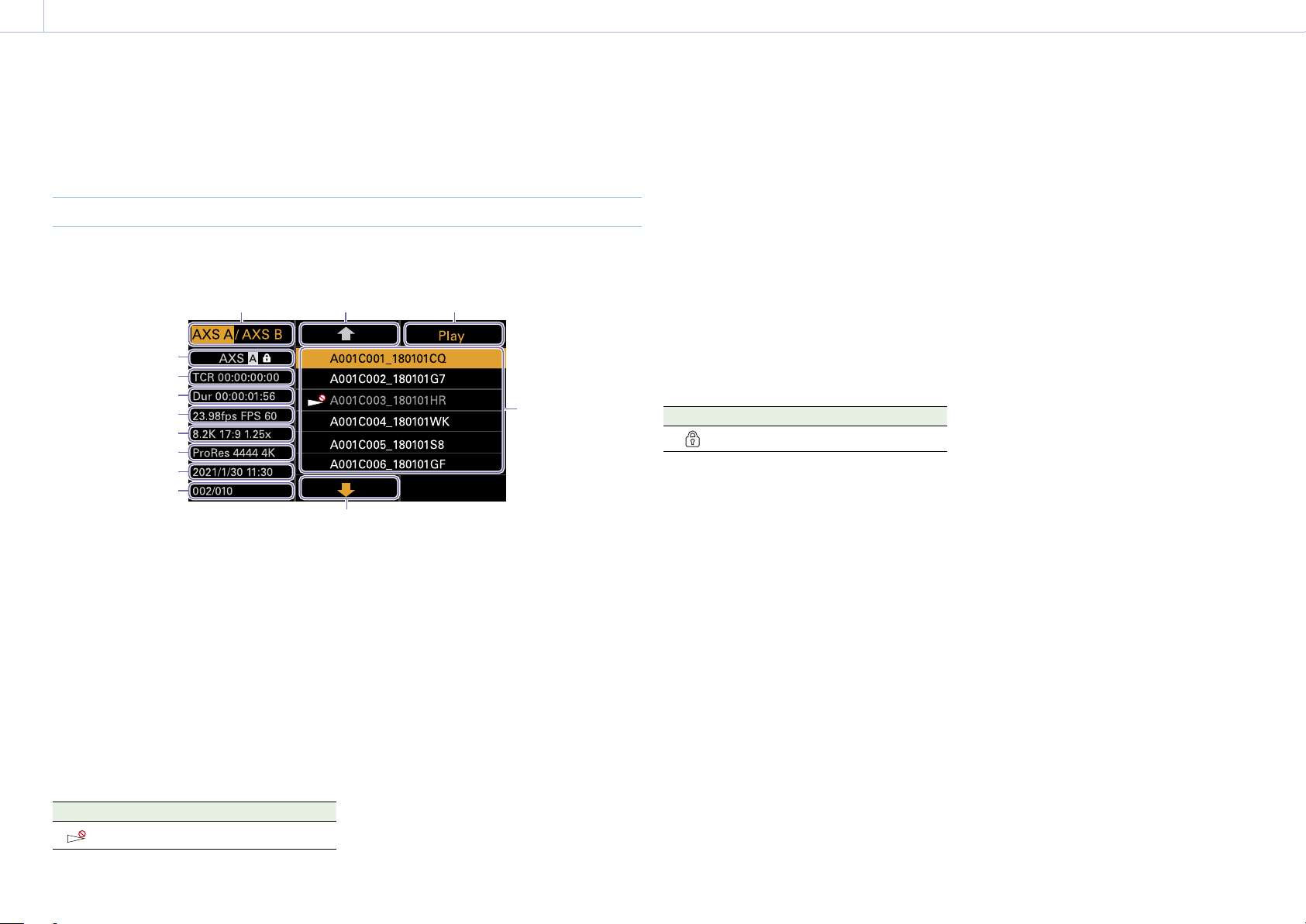
93
3. Camera Operations
Clip Operations on the Sub Display
Clip operations are performed using the clip list screen and the playback screen. You can play a
clip by selecting the clip to play from the clip list screen displayed on the sub display.
Clip List Screen
Press the CLIPS button (page 11) on the Assistant side to display the clip list screen for
playable media on the sub display.
5
4
1 2 3
13
12
11
10
9
8
7
6
1. Media select button
Press ITEM key 1 to switch the media slot for
playback.
2. Cursor up button
Press ITEM key 2 to select the clip to play from
the clip list.
3. Playback start button
Press ITEM key 3 to display the playback
screen (page 16) and start playback.
4. Clip list
Displays a list of clips on the active playback
media. It also displays the clips status using
icons.
Icon Meaning
(Non-playable)
Clip cannot be played
5. Cursor down button
Press ITEM key 5 to select the clip to play from
the clip list.
6. Clip position in playback media
Displays the number of the clip indicated by
the cursor and total number of clips.
7. Creation date and time
Displays the creation date and time of the clip
indicated by the cursor.
8. Format (codec)
Displays the recording format (codec) of the
clip indicated by the cursor.
9. Picture size indicator
Displays the effective picture size when the
clip indicated by the cursor was recorded.
10. Project frame rate/special recording
mode indicator
Displays the project frame rate and special
recording mode of the clip indicated by the
cursor.
11. Duration (Dur)
Displays the duration of the clip indicated by
the cursor.
12. Timecode (TCR)
Displays the timecode of the first frame of the
clip indicated by the cursor.
13. Active playback media
Displays the active playback media of the
displayed list. Displays the media status using
icons.
Icon Meaning
(protect)
Write-protected media
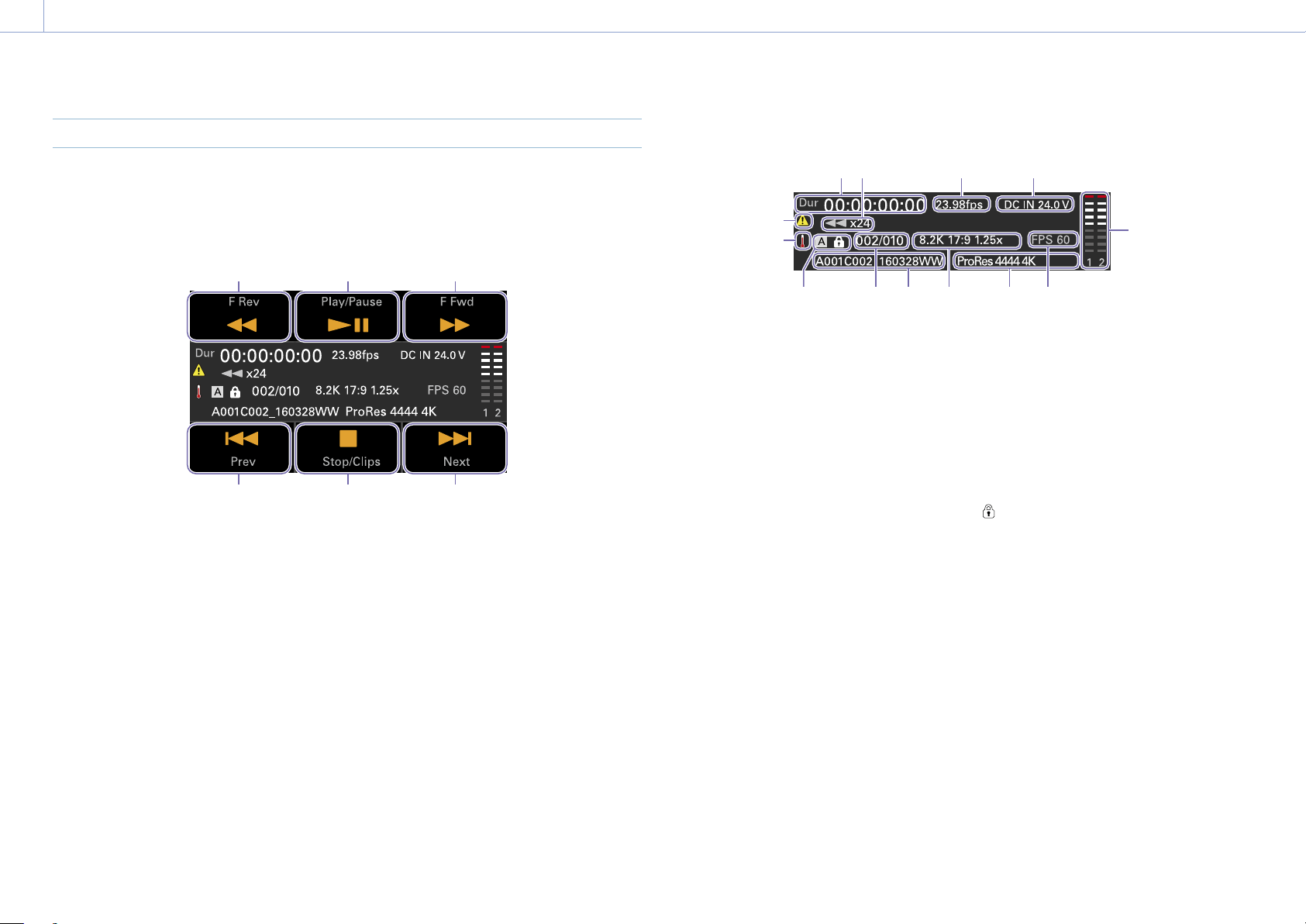
3. Camera Operations: Clip Operations on the Sub Display
94
Playback Screen
The playback screen is displayed when you select a clip to play on the clip list screen and press
the MENU dial or Play button (ITEM key 3).
Function display area
1 2 3
4 5 6
1. F Rev button
Play back at high speed in the reverse
direction.
2. Play/Pause button
Play a clip or pause playback.
3. F Fwd button
Play back at high speed in the forward
direction.
4. Prev button
Skip to the start of the previous clip.
5. Stop/Clips button
Stop playback and return to the clip list screen.
6. Next button
Skip to the start of the next clip.
Status display area
1 2 3 4
5
13
67911
12
810
1. Time data display
Displays the timecode of the playback
position.
2. Playback status indicator
Displays the playback status.
Displays “CALL” when a CALL command is
received.
3. Frame rate indicator
Displays the project frame rate.
4. Power supply voltage/Remaining battery
capacity indicator
Displays the power supply voltage or
remaining battery capacity.
5. Audio level meters
Displays the playback audio level.
6. Special recording mode indicator
Displays the special recording mode
information of the playback clip.
7. Playback clip format (codec) indicator
Displays the format (codec) of the playback
clip.
8. Imager mode indicator
Displays the picture size.
9. Clip name indicator
Displays the name of the clip.
10. Clip number
Displays the Current playback clip number/
Total number of playable clips.
11. Media indicator
Displays the media being played.
A
(protect) icon appears on the right if the
memory card is write-protected.
12. Thermometer icon
Displayed when a high temperature warning
message is issued.
The description is displayed in the Info
category in the menu.
13. Warning icon
Displayed when other than a high temperature
warning message is issued.
The description is displayed in the Info
category in the menu.

95
3. Camera Operations
Playback
You can play recorded clips while the unit is in
standby mode.
[Notes]
• When playing a clip recorded in ProRes, the LUT
configured using LUT Select (page 68) in the
Shooting menu is not applied.
• The playback controls appear on ITEM keys 1 to
6 (page 10). Press an ITEM key to select the
corresponding item.
1 Insert the AXS memory card to play.
2 Press the CLIPS button (page 11) on
the Assistant side.
The clip list on the active playback media
appears on the sub display.
3 Use the button (ITEM key 2), button
(ITEM key 5), or MENU dial to select a clip
to play.
4 Press the MENU dial or the Play button
(ITEM key 3).
The playback image appears on the
viewfinder/monitor screen.
Playback operations
Playback operation is performed using the
buttons on the sub display (page 94).
Play/Pause button: Pause playback. To resume
playback, press this button again.
F Fwd button/F Rev button: Fast forward/
reverse. To return to normal playback,
press the Play/Pause button.
Stop/Clips button: Stop playback and return to
the clip list screen.
Monitoring audio
In normal playback mode, you can monitor the
recorded audio through the built-in speaker
(page 9) or connected headphones.
When headphones are connected to the
headphones connector (page 9), the built-
in speaker is turned off.
You can select the channel to monitor and
adjust the volume using Audio category >
Monitor CH and Monitor Level (page 57) in
the menu.
Cueing up
To play from the start of a clip, press the Prev
button on the sub display (page 94).
You can skip clips and cue-up another clip
by pressing the Prev button or Next button
repeatedly.
Switching between AXS memory cards
When two AXS memory cards are loaded,
press the SLOT SELECT button (page 9) to
switch memory cards. When the clip list screen
is displayed on the sub display, you can also
press ITEM key 1 on the sub display to switch.
[Note]
You cannot switch AXS memory cards during playback.
Continuous playback of cards in slots A and B is not
possible.
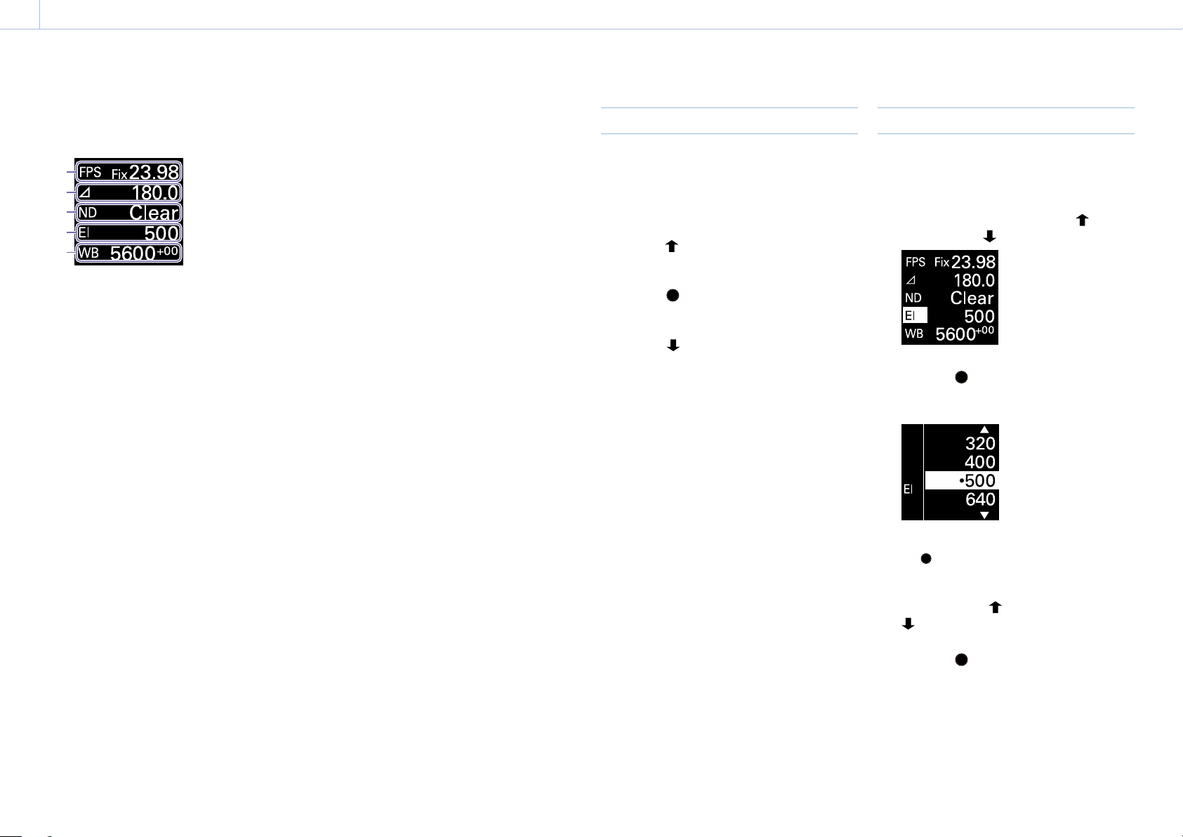
96
3. Camera Operations
Operations on the Home Screen of the Mini Display
You can check the status of the unit and set
basic settings for the unit on the Home screen
of the mini display.
1
2
3
4
5
1. FPS
Sets the shooting frame rate.
2. Shutter
Displays and sets the shutter speed/shutter
angle of the electronic shutter.
3. ND Filter
Displays and sets the density of the ND filter.
4. Exposure Index/Gain
Displays and sets the exposure index (EI), or
displays and sets the gain value (dB units) set
by an RM-B170 or other remote control unit.
[Note]
The gain value is displayed only when Technical
> Special Configuration > RM/RCP Paint Control
(page 91) is set to On in the full menu.
5. WB (White Balance)
Displays and sets the white balance.
Display and operation when RM/RCP
Paint Control is enabled
• The gain value is displayed instead of the
Exposure Index when Technical > Special
Configuration > RM/RCP Paint Control
(page 91) is set to On in the full menu. In
this mode, the EI value cannot be changed,
but the gain value can be changed.
• The following items cannot be operated
when an RM-B170 or other remote control
unit is connected and Technical > Special
Configuration > RM/RCP Paint Control
(page 91) is set to On in the full menu.
Set these using the remote control unit
(page 116).
• Shutter
• WB (White Balance)
Controls
HOME button (page 9)
Press to return to the Home screen.
Unconfirmed changes are canceled.
ITEM key 1 ( (up)) (page 9)
Press to select items on the Home screen.
ITEM key 2 ( (apply)) (page 9)
Press to apply the selected item.
ITEM key 3 ( (down)) (page 9)
Press to select items on the Home screen.
Basic Operation
1 Press ITEM key 1, 2, or 3.
The cursor appears.
2 Select the item to set using the button
(ITEM key 1) or
button (ITEM key 3).
3 Press the (apply) button (ITEM key 2).
The setting value selection screen
appears for the selected item.
[Note]
The (bullet) mark indicates the current setting.
4 Move the cursor to the item or setting
value using the
button (ITEM key 1) or
button (ITEM key 3).
5 Press the (apply) button (ITEM key 2) to
apply the setting.
6 Press the HOME button to hide the cursor.
3. Camera Operations: Operations on the Home Screen of the Mini Display
97
Home Screen Items on the Mini Display
The names of items and corresponding setting values are given below.
Default values are shown underlined and in
bold text.
Item Description
FPS Sets the shooting frame rate.
Variable/Fixed: Switch between variable speed and constant speed
shooting on the Home screen (page 44) of the sub display.
When “Fixed” is selected, the setting is determined by the Project category
> Project Frame Rate (page 54) setting in the menu.
Project Frame Rate Display
23.98
Fix 23.98
24
Fix 24.00
25
Fix 25.00
29.97
Fix 29.97
47.95
Fix 47.95
50
Fix 50.00
59.94
Fix 59.94
When “Variable” is selected, the settings change as follows depending on
the Project category > Imager Mode (page 72) and Recording Format
(page 72) settings in the menu.
X-OCN recording
MPC-3628
Imager Mode Shooting frame rate
8.6K 3:2 1 to 30FPS
8.2K 17:9
7.6K 16:9
1 to 60FPS
5.8K 6:5 1 to 48FPS
5.8K 17:9
5.4K 16:9
1 to 60, 66, 72, 75, 88, 90FPS
Item Description
MPC-3626
Imager Mode Setting
6K 3:2 1 to 60FPS
6K 1.85:1
6K 17:9
5.7K 16:9
1 to 60, 66, 72FPS
6K 2.39:1 1 to 60, 66, 72, 75, 88, 90FPS
4K 6:5 1 to 60, 66, 72FPS
4K 4:3 1 to 60, 66, 72, 75FPS
4K 4:3 Surround View 1 to 30FPS
4K 17:9
3.8K 16:9
1 to 60, 66, 72, 75, 88, 90, 96, 100, 110FPS
4K 17:9 Surround View
3.8K 16:9 Surround View
1 to 48FPS
4K 2.39:1 1 to 60, 66, 72, 75, 88, 90, 96, 100, 110, 120FPS
ProRes recording
MPC-3628
Imager Mode Shooting frame rate
ProRes 4K / QFHD
4444 422 HQ
8.2K 17:9
7.6K 16:9
1 to 60FPS 1 to 60FPS
5.8K 6:5 1 to 48FPS 1 to 48FPS
5.8K 17:9
5.4K 16:9
1 to 60FPS 1 to 60, 66, 72, 75FPS
3. Camera Operations: Operations on the Home Screen of the Mini Display
98
Item Description
MPC-3626
Imager Mode Shooting frame rate
ProRes 4K / QFHD
4444 422 HQ
6K 17:9
5.7K 16:9
1 to 60FPS 1 to 60, 66, 72FPS
6K 2.39:1 1 to 60FPS 1 to 60, 66, 72, 75FPS
4K 6:5 1 to 60FPS 1 to 60, 66, 72FPS
4K 17:9
3.8K 16:9
1 to 60FPS 1 to 60, 66, 72, 75, 88,
90FPS
4K 17:9 Surround View
3.8K 16:9 Surround View
1 to 48FPS 1 to 48FPS
4K 2.39:1 1 to 60FPS 1 to 60, 66, 72, 75, 88,
90FPS
[Note]
Shooting frame rates of 7 or lower cannot be set in the following cases.
– When Base ISO is set to ISO 3200
– When Base ISO is set to ISO 2500 and the recording format is ProRes
Exposure Index Sets the EI value. The settings change as follows depending on the Project
> Basic Setting > Base ISO (page 72) setting in the full menu.
MPC-3628
Base ISO 800:
200EI/250EI/320EI/400EI/500EI/640EI/800EI/1000EI/1250EI/1600EI/
2000EI/2500EI/3200EI
Base ISO 3200:
800EI/1000EI/1250EI/1600EI/2000EI/2500EI/
3200EI/4000EI/5000EI/
6400EI/8000EI/10000EI/12800EI
MPC-3626
ISO 500:
125EI/160EI/200EI/250EI/320EI/400EI/500EI/640EI/800EI/1000EI/
1250EI/1600EI/2000EI
ISO 2500:
640EI/800EI/1000EI/1250EI/1600EI/2000EI/
2500EI/3200EI/4000EI/
5000EI/6400EI/8000EI/10000EI
Gain
Sets the base sensitivity.
–6dB/–3dB/
0dB/3dB/6dB/9dB/12dB/15dB/18dB
[Note]
Configurable only when an RM-B170 or other remote control unit is connected and
Technical > Special Configuration > RM/RCP Paint Control (page 91) is set to On in
the full menu.
Item Description
Shutter
Sets the electronic shutter angle/shutter speed.
Select from preset values registered as shutter steps.
[Note]
Not available when the electronic shutter operation is set to Continuous.
Displays the following selection options depending on the Technical >
System Configuration > Shutter Mode (page 87) setting in the full menu.
Angle (Δ): Shutter angle indicator
360.0/
180.0/172.8/144.0/90.0/45.0/22.5/11.2/5.6
1)
Speed (SS): Shutter speed indicator
1/24, 1/25, 1/30, 1/48, 1/50, 1/60, 1/100, 1/120, 1/250, 1/500, 1/1000,
1/2000
1)
ND Filter
Sets the density of the ND filter. The following settings are available.
Clear/0.3/0.6/0.9/1.2/1.5/1.8/2.1/2.4
WB (White Balance)
Sets the color temperature of the white balance.
Select from preset values registered as WB steps.
3200K+00/4300K+00/5500K+00
1)
1) The selection options can be changed using Step Edit on the Home screen of the sub display.
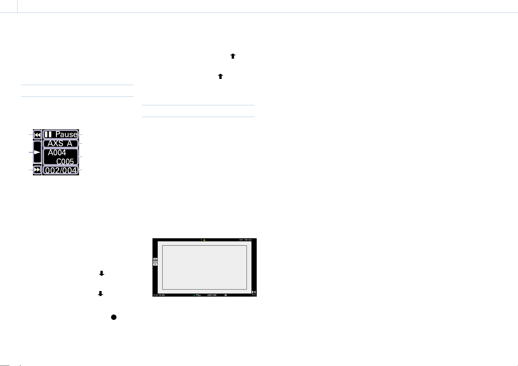
99
3. Camera Operations
Clip Operations on the Mini Display
You can play a clip by selecting the clip to play
from the clip screen displayed on the mini
display.
Clip Screen
Press the CLIPS button (page 9) on the
Operator side to display the clip screen for
playable media on the mini display.
7
6
5
1
2
3
4
1. Playback status indicator
Displays the clip playback status.
2. Active playback media
Displays the active playback media of the
selected clip.
3. Clip name indicator
Displays the clip name of the selected clip.
4. Clip position in playback media
Displays the clip number/total number of the
selected clip.
5. F Fwd/Next button
Jumps to the next clip when the
button
(ITEM key 3) is pressed while playback is
paused.
Fast forwards the clip when the
button
(ITEM key 3) is pressed during playback.
6. Play/Pause button
Plays/pauses clip playback when the
button (ITEM key 2) is pressed.
7. F Rev/Prev button
Jumps to the previous clip when the
button
(ITEM key 1) is pressed while playback is
paused.
Fast reverses the clip when the
button
(ITEM key 1) is pressed during playback.
Playback
You can play recorded clips while the unit is in
standby mode.
1 Insert the AXS memory card to play.
2 Press the CLIPS button (page 9) on
the Operator side.
The active playback clip appears on the
mini display.
3 Use the Prev button (ITEM key 1) or Next
button (ITEM key 3) to select a clip to play.
4 Press the Play/Pause button (ITEM key 2).
The playback image appears on the
viewfinder/monitor screen.
Playback operations
Playback operation is performed using the
buttons on the mini display (page 99).
Play/Pause button: Pause playback. To resume
playback, press this button again.
F Fwd button/F Rev button: Fast forward/
reverse. To return to normal playback, press
the Play/Pause button.
Monitoring audio
In normal playback mode, you can monitor the
recorded audio through the built-in speaker
(page 9) or connected headphones.
When headphones are connected to the
headphones connector (page 9), the built-
in speaker is turned off.
You can select the channel to monitor and
adjust the volume using Audio category >
Monitor CH and Monitor Level (page 57) in
the menu.
Switching between AXS memory cards
When two AXS memory cards are loaded,
press the SLOT SELECT button (page 9) to
switch memory cards. When the clip list screen
is displayed on the sub display, you can also
press ITEM key 1 on the sub display to switch.
[Note]
You cannot switch AXS memory cards during playback.
Continuous playback of cards in slots A and B is not
possible.
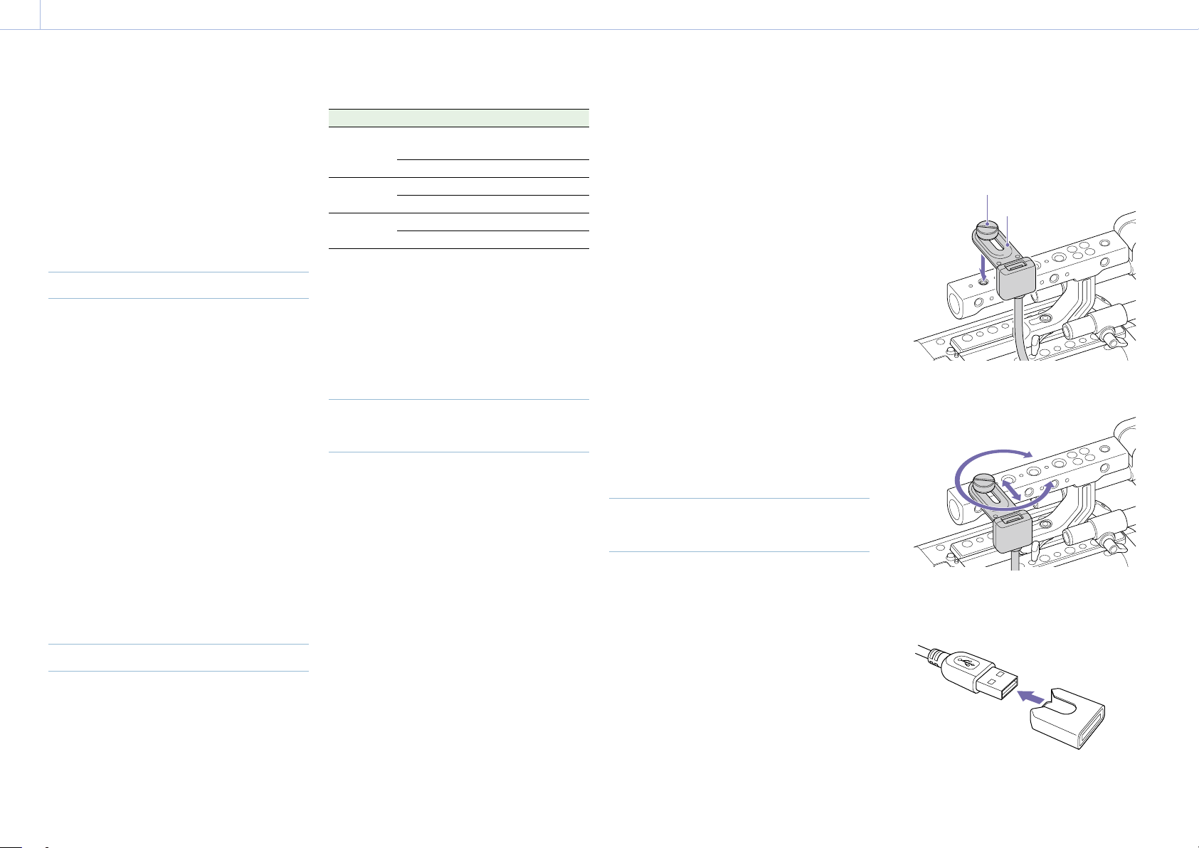
100
4. Network
Network Setup and Operations
Connecting the unit to a network allows you
to control various settings of the unit from a
computer, smartphone, tablet, or other device
and to display information about the unit.
[Note]
When connecting to the Internet, connect via a router,
a device with a router function, or a firewall to avoid
external attack.
Overview of Network Function
When the unit and a device are connected
via wired LAN or wireless LAN, the unit can
be accessed from a browser on the device,
displaying the web remote control and
enabling the following operations.
• Control recording on the unit (page 103)
• Control playback on the unit (page 103)
• Configure shooting settings on the unit
(page 103)
• Control the lens attached to the unit
(page 104)
• Configure and operate assignable buttons
on the unit (page 104)
Using the web remote control allows you to
start/stop recording or configure settings
remotely, and is useful in applications where
the unit is fixed in a remote location or
mounted on a crane, for example.
Compatible Devices
You can use a computer, smartphone, or tablet
to configure and operate the unit. The verified
devices, OS, and browsers are shown in the
following table.
Device OS Browser
Computer Microsoft Windows
10/11
Chrome
macOS 11.x Safari
Smartphone
Android 10.x/11.x Chrome
iOS 14.x/15 Safari
Tablet Android 10.x/11.x Chrome
iPadOS 14.x Safari
[Note]
The controls may not be displayed normally, depending
on the version of the browser you are using. Operation
in the following versions of the browsers has been
verified.
Safari: 14/15
Chrome: 93
Connecting the Unit and Device
via Wired LAN
You can connect the unit to a device via a
wired LAN connection or via a router using the
network connector of the unit.
1 Connect the network connector
(page 12) of the unit and computer
using a LAN cable. Or connect the network
connector of the unit and router using a
LAN cable.
2 Set Technical > Network > Setting
(page 87) in the full menu to LAN.
[Note]
Grayed out and cannot be changed if a password is
not configured using Technical > Authentication >
Password (page 87) in the full menu.
3 Configure the unit.
To obtain the IP address of the unit
automatically:
Set Technical > Network > LAN > DHCP
(page 88) in the full menu to On, then
select Set to apply the setting.
To enter the IP address of the unit
manually:
Set Technical > Network > LAN > DHCP in
the full menu to Off, enter the specified IP
address using LAN > IP Address, and
select Set to apply the setting.
[Note]
Select Set on the Technical > Network > LAN setup
screen in the full menu. If Set is not selected, the
configured settings are not applied.
When the wired LAN connection is
enabled, the LAN icon of the network
connection status indicator (page 15) is
displayed on the viewfinder/monitor
screen.
Connecting the Unit and Device
via Wireless LAN
The unit can connect to devices using wireless
LAN connection by attaching the CBK-WA02
Wireless LAN Adaptor (option) to the unit.
Attaching the CBK-WA02
[Note]
Always turn the unit off before connecting the CBK-
WA02.
1 Attach the USB extension adaptor to the
point shown in the following diagram, and
turn the retaining screw clockwise to
secure it in position.
Retaining screw
USB extension adaptor
You can adjust the position of the USB
extension adaptor over the range shown
in the following diagram.
2 Attach the protective cap (supplied) to the
USB connector of the USB extension
adaptor.
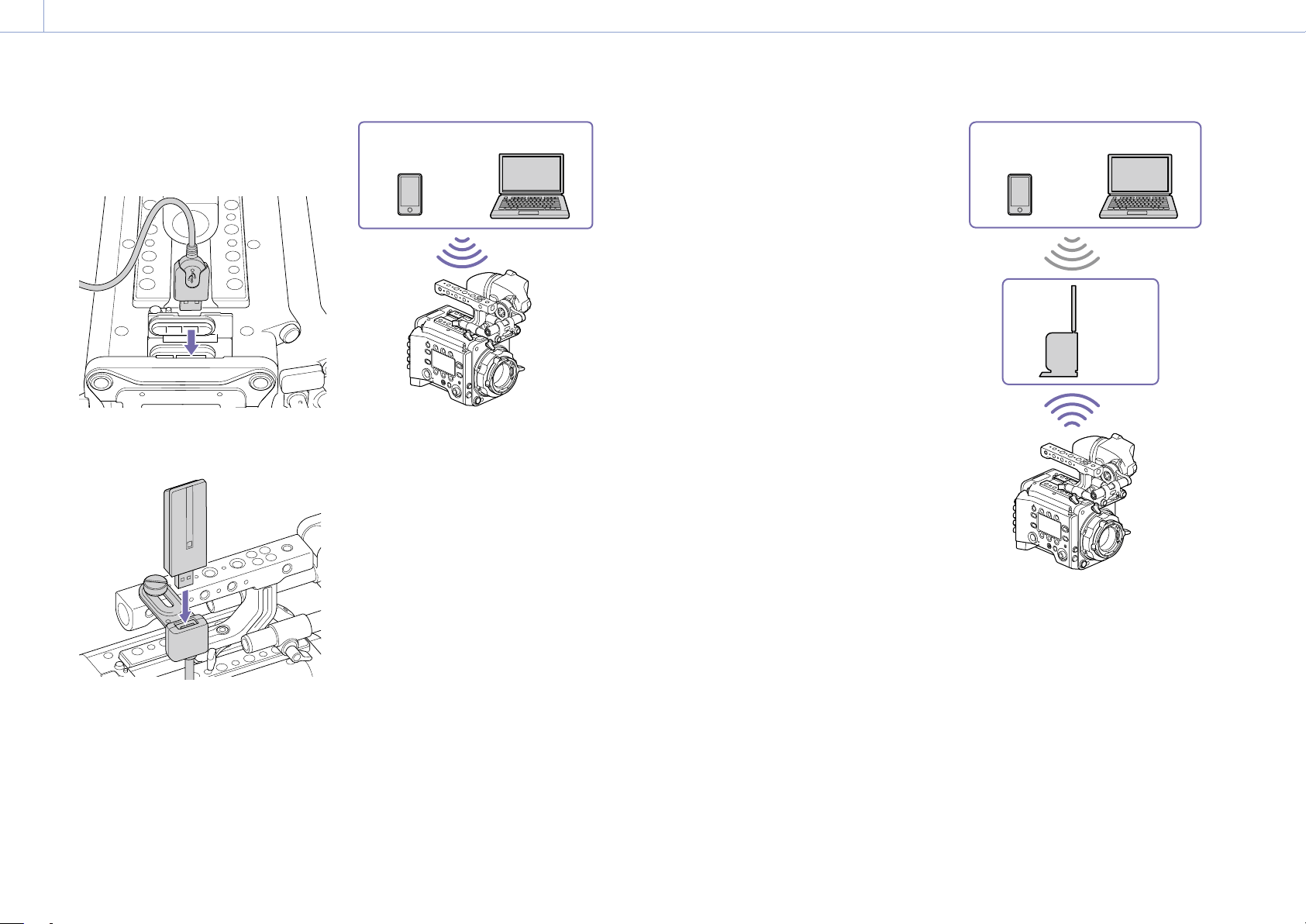
4. Network: Network Setup and Operations
101
3 Open the cover of the external device
connector block, and insert the USB
connector of the USB extension adaptor
into the external device connector.
4 Insert the CBK-WA02 into the USB
connector of the USB extension adaptor.
Connecting in access point mode
The unit can connect to devices that are set up
as an access point via wireless LAN.
Smartphone/
Tablet
Computer
Connecting using WPS-equipped devices
Devices that support WPS can be connected
using WPS.
1 Set Technical > Network > Setting
(page 87) in the full menu to Wireless.
[Note]
Grayed out and cannot be changed if a password is
not configured using Technical > Authentication >
Password (page 87) in the full menu.
2 Set Technical > Network > Wireless >
Network Mode (page 88) in the full
menu to Access Point.
3 Select Technical > Network > Wireless >
WPS (page 88) in the full menu.
4 Select Run by turning the MENU dial, then
press the MENU dial.
5 Open the device Network Settings or
Wi-Fi Settings, and turn Wi-Fi on.
6 Press the WPS push button in the device
Network Settings or Wi-Fi Settings
preferences.
[Note]
The steps will vary depending on the device used.
Connecting using SSID and password on the
device
Connect by entering the SSID and password
on the device.
1 Set Technical > Network > Setting
(page 87) in the full menu to Wireless.
[Note]
Grayed out and cannot be changed if a password is
not configured using Technical > Authentication >
Password (page 87) in the full menu.
2 Set Technical > Network > Wireless >
Network Mode (page 88) in the full
menu to Access Point.
3 Open the device Network Settings or
Wi-Fi Settings, and turn Wi-Fi on.
4 Select the unit’s SSID from the Wi-Fi
network SSID list, then enter a password
to connect.
For the unit’s SSID and password, see
Technical > Network > Wireless > SSID and
Password (page 88) in the full menu.
[Note]
The steps will vary depending on the device used.
Connecting in station mode
The unit can connect to existing wireless LAN
access points as a client.
The device connects via the access point.
Smartphone/
Tablet
Computer
Access
point
Connecting to an access point using WPS
If an access point supports the WPS function,
you can connect using a basic setting.
1 Turn the access point on.
2 Turn the unit on.
3 Set Technical > Network > Setting
(page 87) in the full menu to Wireless.
[Note]
Grayed out and cannot be changed if a password is
not configured using Technical > Authentication >
Password (page 87) in the full menu.

4. Network: Network Setup and Operations
102
4 Set Technical > Network > Wireless >
Network Mode (page 88) in the full
menu to Station.
5 Select Technical > Network > Wireless >
WPS (page 88) in the full menu.
6 Select Run by turning the MENU dial, then
press the MENU dial.
7 Press the access point WPS button.
For details about WPS button operation,
refer to the instruction manual for the
access point.
[Note]
If the connection fails, perform the procedure again from
step
1.
Connecting by entering a SSID and password
Connect by entering the SSID and password
on the unit.
1 Set Technical > Network > Setting
(page 87) in the full menu to Wireless.
[Note]
Grayed out and cannot be changed if a password is
not configured using Technical > Authentication >
Password (page 87) in the full menu.
2 Set Technical > Network > Wireless >
Network Mode (page 88) in the full
menu to Station.
3 Set the following items in Technical >
Network > Wireless (page 88) in the full
menu.
• SSID
• Password
• DHCP
• IP Address
• Subnet Mask
4 Select Set to confirm.
[Note]
Always use Set to confirm the settings. If the settings are
not confirmed using Set, the configured settings are not
applied.
Connecting using access point auto detection
The unit can connect by detecting connection
access points automatically, without having to
enter the SSID manually.
1 Set Technical > Network > Setting
(page 87) in the full menu to Wireless.
[Note]
Grayed out and cannot be changed if a password is
not configured using Technical > Authentication >
Password (page 87) in the full menu.
2 Set Technical > Network > Wireless >
Network Mode (page 88) in the full
menu to Station.
3 Select Technical > Network > Wireless >
Scan Networks (page 88) in the full
menu.
4 Select Run by turning the MENU dial, then
press the MENU dial.
The unit starts auto detection of
connection access points. When auto
detection finishes, networks available for
connection are displayed in a list.
5 Select the network to be connected by
turning the MENU dial, then press the
MENU dial.
6 Select Set to confirm.
A password input screen appears.
7 Enter the password, then select Done.
The Wireless preferences screen appears.
8 Set the following items in Technical >
Network > Wireless in the full menu, then
select Set to confirm.
• DHCP
• IP Address
• Subnet Mask
[Note]
Always use Set to confirm the settings. If the settings are
not confirmed using Set, the configured settings are not
applied.
Displaying the Web Remote
Control
The web remote control is displayed when
the unit is accessed from the browser of a
device. The web remote control screen is
automatically resized to match the screen size
of the connected device.
1 Connect the unit and device as described
in “Connecting the Unit and Device via
Wired LAN” or “Connecting the Unit and
Device via Wireless LAN”.
2 Launch a browser on the device and enter
“http://IP address of unit/rm.html” in the
URL bar.
You can check the IP address of the unit
using Info category > System > IP Address
(page 58) in the menu.
For example, if the IP address is
192.168.1.1, enter “http://192.168.1.1/
rm.html” in the URL bar.
3 Enter the user name and password
(Technical > Authentication (page 87)
in the full menu) on the browser screen.
When connection is successful, the web
remote control screen appears on the
device.
[Note]
The page may not be displayed correctly on a
smartphone or other device if the viewing mode is set
to mobile pages. Change the viewing mode to desktop
pages.
Web Remote Control Screen
Global Menu
Select (Global Menu) at the top left of
the web remote control screen to display the
Global Menu. Select the item you want to
configure.
Camera Control screen
The Camera Control screen contains the
Camera screen, Lens screen, and Info screen.
Select the Camera tab to display the Camera
screen, the Lens tab to display the Lens
screen, and the Info tab to display the Info
screen.
Various display items and operation buttons
are displayed on the Camera Control screen
(common to Camera screen, Lens screen, Info
screen, and playback screen).
• Network connection status (Connected/
Disconnected)
• Camera ID*
• Rec button
• Assignable buttons (1 to 4, A to C)
* The Camera ID text color is the same color set using
Frame Line A/B Setup > Color.
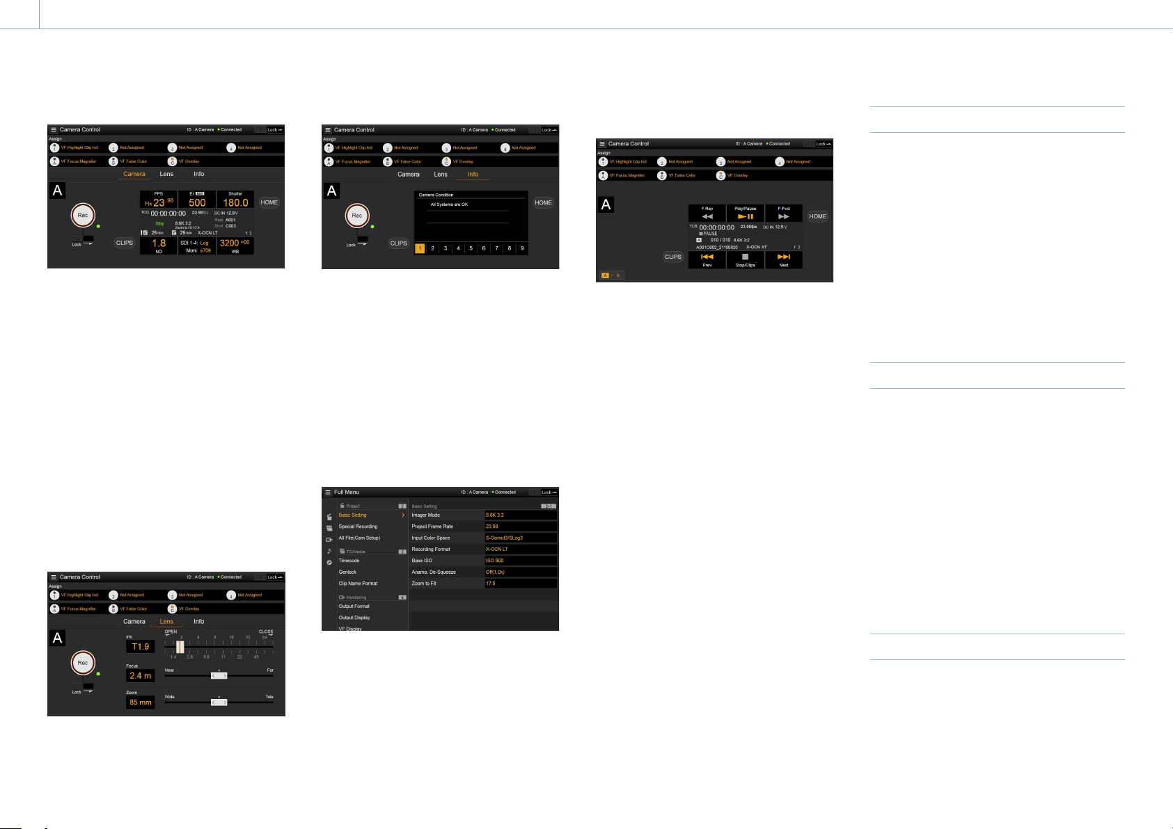
4. Network: Network Setup and Operations
103
Camera screen
You can configure the same items that are
displayed on the Home screen of the sub
display on the Camera screen.
[Note]
Similarly as for the sub display screen, the EI display
area switches to become the Gain display area and
restrictions apply to the items (page 38) that can be
operated when Technical > Special Configuration > RM/
RCP Paint Control (page 91) is set to On in the full
menu.
• Shooting settings (page 36)
FPS, EI, Shutter, ND, LUT, WB
• Camera status display (page 37)
Operating status, time data, audio level
meter, clip name, recording format,
media status/free space, battery voltage/
remaining battery capacity
Lens screen
Lens controls for zoom, focus, and iris are
displayed on the Lens screen.
Info screen
The Info screen displays the same contents
as the Info category (page 58) of the sub
display menu screen, allowing you to check
the status of the camera, media, and battery.
Full Menu screen
Select Full Menu in the Global Menu to display
the full menu screen in order to configure
items (page 64).
[Note]
Some items may not be configurable from the web
remote control.
OSS (Open Source Software) Information
screen
Select OSS Information in the Global Menu to
display the open source software information.
Playback screen
You can play clips on the playback screen.
Information about the playback clip is also
displayed in the status display area on the
screen.
• Function display (page 94)
F Rev, Play/Pause, F Fwd, Prev, Stop/Clips,
Next
• Playback status display (page 94)
Time data, clip number, frame rate/playback
clip picture size, special recording mode,
audio level meter, playback clip format
(codec), icon (protection), clip name,
playback media, and playback status.
HOME button
Press the HOME button to return to the
Camera screen.
When the camera is in playback mode,
pressing the HOME button returns to the
camera shooting status even when the
playback screen is displayed on the web
remote control screen.
CLIPS button
Press the CLIPS button to return to the
playback screen. (The unit switches to the clip
list screen (page 93).)
Recording
Press the Rec button on the Camera Control
screen to start recording and to display the
REC lamp in red. Click again to stop recording.
The Rec button is enabled when the REC
ACTIVE lamp below and to the right of the Rec
button is green.
To lock the Rec button
Slide the Lock slider below the Rec button to
the right to disable the Rec button operation.
Playback
Press the CLIPS button on the Camera screen
to return to the playback screen in playback
state. (The sub display on the unit displays the
clip list screen (page 93).)
Select the clip you want to play on the
playback screen, and use the playback
controls to play the clip.
To switch between playback media
Press the media select button to switch the
media slot for playback.
Configuring Shooting Settings
You can configure and operate the same items
that are displayed on the Home screen of the
sub display of the unit on the Camera screen.
[Note]
Step Edit operation for Shutter is not supported.
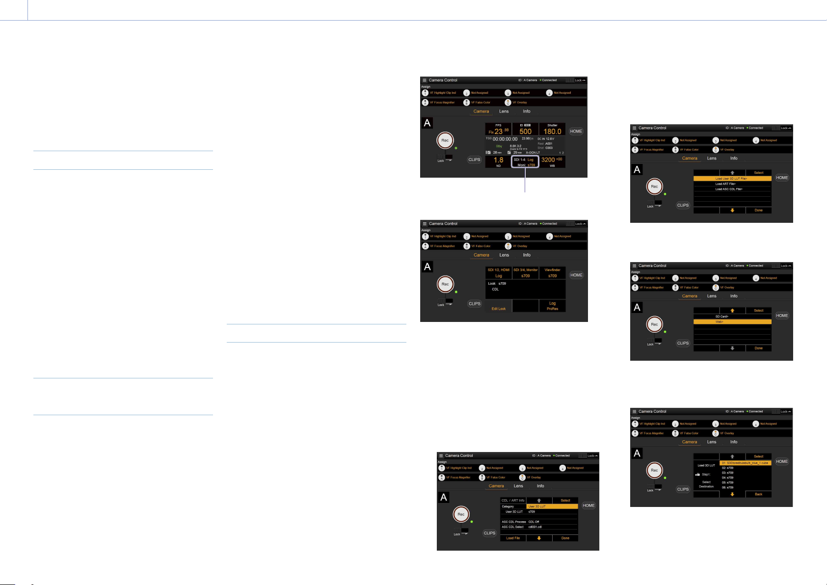
4. Network: Network Setup and Operations
104
The operation is the same as on the Home
screen of the sub display.
“Operations on the Home Screen of the Sub Display”
(page 38)
Controlling the Lens
You can check the status of E-mount lens
settings (zoom, focus, iris) on the Lens
screen, and also control the zoom, focus,
and iris using sliders if the attached lens is
controllable.
PL-mount Cooke lens communication control
is supported on the Lens screen.
Also, 12-pin lens communication control is
supported on the Lens screen.
[Note]
The sliders are grayed out and cannot be operated when
an RM-B170 or other remote control unit is connected
and Technical > Special Configuration > RM/RCP Paint
Control (page 91) is set to On in the full menu. The
focus and zoom sliders are grayed out when remote
control of focus and zoom, respectively, are enabled.
Configuring/Operating Assignable
Buttons
Assignable buttons 1 to 4 and viewfinder
assignable buttons A to C are displayed on the
Camera Control screen.
Press assignable buttons 1 to 4 and DVF-
EL200 assignable buttons A to C to toggle the
assigned functions between on/off (enabled/
disabled) or to activate the assigned functions
in the same way as assignable buttons on the
unit.
Select the function name of an assignable
button to display selection options in a pull-
down. Select an option to change the function
assigned to the assignable button.
“Functions that can be Assigned to Assignable Buttons 1 to
4” (page 50)
“Functions that can be Assigned to Viewfinder
(DVF-EL200) Assignable Buttons A to C” (page 52)
[Note]
Functions assigned to assignable switches that are
enabled only while a button is pressed or are enabled
by a long press cannot be operated from the assignable
buttons of the web remote control. These comprise the
following functions.
– Press&Hold for SDI12 Log
– Press&Hold for SDI34 Log
– Press & Hold for Moni Log
– Press & Hold for VF Log
– Iris Open (1/16 stop)
– Iris Close (1/16 stop)
– Monitor Focus Magnifier (when Monitor Magnifier
Mode is set to Press & Hold)
– VF Focus Magnifier (when VF Magnifier Mode is set
to Press & Hold)
Loading Various Files
You can load a User 3D LUT file, ART file,
or ASC CDL file into the unit using the LUT
selection screen of the Camera screen.
Displaying the LUT selection screen
Click/tap the LUT selection area on the Home
screen of the sub display of the Camera
screen.
LUT selection area
The LUT selection screen appears.
Loading a User 3D LUT file
You can load a User 3D LUT file into the unit
from a network-connected device.
1 Click/tap the Edit Look button on the LUT
selection screen.
The Look selection screen appears.
2 Click/tap the Load File button.
A file type selection screen appears.
3 Move the cursor to Load User 3D LUT File
and click/tap the Select button.
A load destination selection screen
appears.
4 Move the cursor to Web and click/tap the
Select button.
The load destination numbers (01 to 16)
are displayed.
A file name is displayed for loaded
numbers.
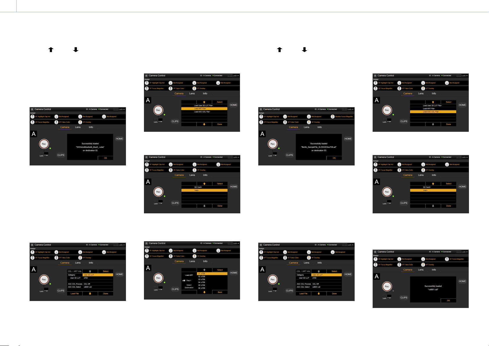
4. Network: Network Setup and Operations
105
5 Use the button, button, or direct
touch to move the cursor to a load
destination number and then click/tap
the Select button.
6 Open a folder on the network-connected
device and select the file to load.
When the file is loaded successfully,
“Successfully loaded” is displayed.
Loading an ART file
You can load an ART file into the unit from a
network-connected device.
1 Click/tap the Edit Look button on the LUT
selection screen.
The Look selection screen appears.
2 Click/tap the Load File button.
A file type selection screen appears.
3 Move the cursor to Load ART File and
click/tap the Select button.
A load destination selection screen
appears.
4 Move the cursor to Web and click/tap the
Select button.
The load destination numbers (01 to 16)
are displayed.
A file name is displayed for loaded
numbers.
5 Use the button, button, or direct
touch to move the cursor to a load
destination number and then click/tap
the Select button.
6 Open a folder on the network-connected
device and select the file to load.
When the file is loaded successfully,
“Successfully loaded” is displayed.
Loading an ASC CDL file
You can load an ASC CDL file into the unit from
a network-connected device.
1 Click/tap the Edit Look button on the LUT
selection screen.
The Look selection screen appears.
2 Click/tap the Load File button.
A file type selection screen appears.
3 Move the cursor to Load ASC CDL File and
click/tap the Select button.
A load destination selection screen
appears.
4 Move the cursor to Web and click/tap the
Select button.
5 Open a folder on the network-connected
device and select the file to load.
When the file is loaded successfully,
“Successfully loaded” is displayed.
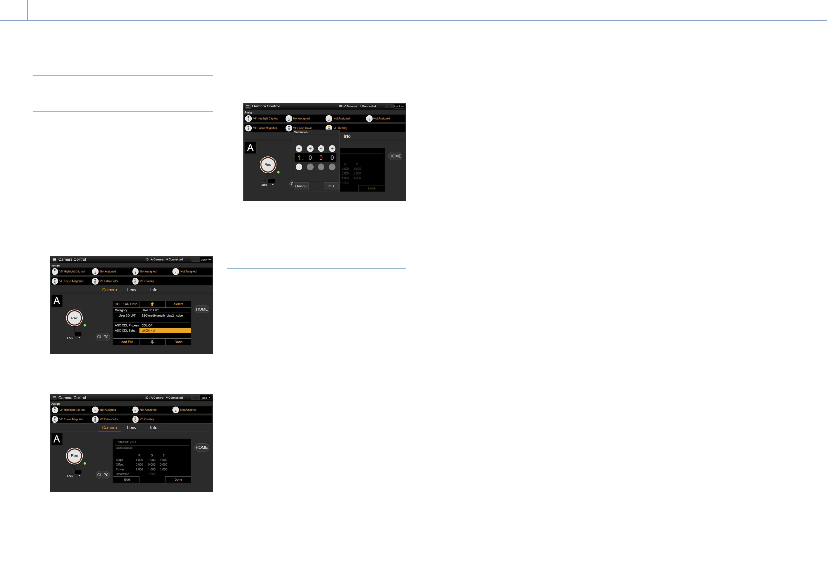
4. Network: Network Setup and Operations
106
Changing Saturation in an ASC
CDL file
You can change the Saturation setting in an
ASC CDL file using the LUT selection screen of
the Camera screen.
1 Click/tap the Edit Look button on the LUT
selection screen.
The Look selection screen appears.
2 Move the cursor to ASC CDL Select, and
click/tap CDL/ART Info.
The ASC CDL file information screen
appears.
3 Click/tap the Edit button.
The Saturation edit screen appears.
4 Click/tap the + button or – button to
change the setting.
5 Click/tap the OK button to apply the
setting.
Locking the Web Remote Control
Screen
You can disable web remote control screen
operation by sliding the Lock slider to the right
on the top right of the web remote control
screen.

107
5. Shooting
Basic Operation
Basic recording can be performed with the
following procedures.
1 Make sure that the necessary devices are
attached to the unit and power is supplied
to them.
2 Set the power switch (page 9) to the
ON position.
The recording screen is displayed on the
viewfinder screen.
3 Load the memory card(s).
If you load two AXS memory cards,
recording is continued by automatically
switching to the second card when the
first card becomes full.
4 Press the REC button (pages
9
,
11
).
The REC lamp lights and recording begins.
[Note]
If the unit cannot start recording immediately after
the pressing the REC button, the REC lamp flashes.
The REC lamp lights when recording starts.
5 To stop recording, press the REC button
again.
Recording stops and the unit enters STBY
(recording standby) mode.
When you stop recording, the video,
audio, and subsidiary data from the start
to the end of the recording are recorded
as a single clip.
Clip names
Clip names are recorded using the “Cam ID
+ Reel#” format. The clip name is created
according to the following rules.
• When there is already a clip that is stored
using the “Cam ID + Reel#” name format on
the inserted AXS memory card, the new file
inherits from the last file.
Example: If “B002C003_XXXXXXXX” exists on
the AXS memory card, the next created clip
will be named “B002C004_XXXXXXXX.”
• If the inserted AXS memory card has no
files, “1” is added to the Reel Number of the
clip that was recorded last.
Example: If you record on empty card 2 after
recording up to “D001CXXX_XXXXXXXX” on
card 1, the next created clip will be named
“D002C001_XXXXXXXX.” The clip name is
displayed underlined until recording starts.
• If you set Camera ID and Reel Number using
the TC/Media category in the menu, that
information is applied.
Example: If you change Camera ID to “F”
and Reel Number to “001” in the menu for
the AXS memory card that has recorded up
to “E003CXXX_XXXXXXXX,” the next clip will
be named “F001CXXX_XXXXXXXX.” When
you change Camera ID only, Reel Number is
changed to “001.”

108
5. Shooting
Useful Functions
User Frame Line Display
You can select whether to display arbitrarily
configured user frame lines or a fixed aspect
ratio.
User Frame Line 1 and User Frame Line 2 can
be set for user frame lines.
To set user-configured lines, select Variable
using Monitoring > User Frame Line 1
(page 81) or User Frame Line 2 (page 82)
> Select in the full menu, and specify the
Width, Height, H Position, and V Position menu
items.
To set a fixed aspect ratio, select Preset using
Monitoring > User Frame Line 1 (page 81) or
User Frame Line 2 (page 82) > Select in the
full menu, and specify the Preset Aspect Ratio,
Scaling, and Preset Aspect Ratio Type menu
items.
You can check the aspect ratio, number of
pixels, and anamorphic ratio of configured
user frame lines for both user-configured
lines or a fixed aspect ratio using Aspect
Ratio(Pixels) (page 82).
[Notes]
• The User Frame Line 2 > Preset Aspect Ratio Type
setting is set to Line (fixed).
• The anamorphic ratio is not displayed for effective
picture size (Imager Mode) settings for which the
anamorphic ratio cannot be configured.
Assignable button operations
You can show/hide User Frame Line 1 and
User Frame Line 2 configured for Line A by
assigning Line A: User Frame Disp. to any
of assignable buttons 1 to 4, viewfinder
assignable buttons A to C, and ITEM keys 1 to 5
(page 48).
Each time the assignable button is pressed,
the display switches between User Frame Line
1 and 2 display User Frame Line 1 display
User Frame Line 2 display User Frame Line 1
and 2 hidden.
Similarly, you can show/hide User Frame Line
1 and User Frame Line 2 configured for Line
B by assigning Line B: User Frame Disp. to an
assignable button or key.
You can also show/hide Aspect Ratio
configured for Line A or Line B by assigning
Line A: Aspect Ratio Disp. or Line B: Aspect
Ratio Disp. to any of assignable buttons 1 to
4, viewfinder assignable buttons A to C, and
ITEM keys 1 to 5. Each time the assignable
button is pressed, the display switches
between Aspect Ratio display and Aspect
Ratio hidden.
Picture Cache Recording
The unit always maintains a cache of video
and audio data in memory when shooting,
allowing you to record several seconds of
footage before the start of recording.
When you start recording with Project
> Special Recording > Cache Rec Select
(page 73) set to On in the full menu, video
of duration set by Project > Special Recording
> Max Cache Rec Duration (page 73) is
recorded retroactively.
You can also turn picture cache recording on/
off using an assignable button assigned with
the Picture Cache Rec function.
[Notes]
• Restrictions to the Max Cache Rec Duration setting
may apply, depending on the project frame rate,
recording format, and recording media. For details,
see page 73.
• Changing system settings, such as the recording
format, clears all images stored in memory.
Consequently, images shot just before changing
settings cannot be recorded, if recording is started
immediately after changing settings. Picture cache
mode is automatically released.
• The picture cache settings cannot be changed during
recording.
Recording Review (Rec Review)
You can review the last recorded clip on
the screen by assigning the Rec Review
function to one of assignable buttons 1 to 4
(page 48).
When you stop recording and press the button
assigned with Rec Review, the clip is played at
normal speed starting from the first frame.
The clip is played to the end, then Rec Review
ends and the unit returns to STBY (recording
standby) mode.
If the HOME button is pressed on the Operator
side or Assistant side during playback,
playback stops and the unit switches to
shooting mode.
Zoom to Fit
When shooting and recording a scene that
is wider than the actual desired picture size,
you can enlarge the recorded image to the
desired picture size on the viewfinder screen
or monitor screen.
Configure using the Project > Basic Setting
> Zoom to Fit (page 73) setting in the full
menu.
[Note]
During playback, the Zoom to Fit function is disabled.

5. Shooting: Useful Functions
109
High-Definition Focus Magnifier
Function
You can magnify the display for the viewfinder
screen or Monitor output.
By pressing the FOCUS MAG button of the
viewfinder (DVF-EL200, DVF-L700) attached
to the unit, or pressing an assignable button
assigned with the VF Focus Magnifier function,
you can expand the center part of the
viewfinder screen, making it is easier to adjust
the focus. By pressing an assignable button
assigned with the Monitor Focus Magnifier
function, you can expand the center part of
the Monitor output image, making it is easier
to adjust the focus.
The magnified display does not affect the
recorded image or other output signals, other
than the Monitor output.
Normal focus magnification reduces the
resolution because it simply magnifies a
part of the displayed image. However, the
two-times (×2) focusing by the unit provides
focus magnification while maintaining the
display resolution by cutting out the portion
to magnify from the 4K image instead of the
recorded image or other output signals, other
than the Monitor output.
Four-times (×4) focus magnification selection
is also supported using the 4K image cutout
function.
The following focus magnification functions
can be assigned to an assignable button
(page 48).
Viewfinder focus magnifier function: VF Focus
Magnifier
Monitor output focus magnifier function:
Monitor Focus Magnifier
The magnification sequence of the FOCUS
MAG button and assignable buttons assigned
with a focus magnification function is set
using the following items.
Viewfinder screen: Monitoring > VF Display >
VF Magnifier Ratio (page 78) in the full
menu
Monitor output: Monitoring > Output Display >
Monitor Magnifier Ratio (page 77) in the
full menu
When VF Magnifier Ratio is set to ×2.0/×4.0,
the magnification sequence each time you
press an assignable button assigned with VF
Focus Magnifier is ×2.0 ×4.0 ×1.0
×2.0.
Similarly, when Monitor Magnifier Ratio is set
to ×2.0/×4.0, the magnification changes each
time you press an assignable button assigned
with Monitor Focus Magnifier.
[Notes]
• In High Frame Rate mode (shooting frame rate of
61 fps or higher), the ×2/×4 focus display image
resolution decreases because cutout display from a
4K image is not supported.
• When Project Frame Rate is set to 59.94 or 50 and
the Monitor output setting is 1920×1080P, Monitor
Magnifier Ratio cannot be set to ×4.0 or ×2.0/×4.0.
When the Monitor output setting is 1920×1080i,
Monitor Focus Magnifier does not function.
• Monitor Focus Magnifier is also applied to the HDMI
output if the HDMI output has the same output
format as the Monitor output. You can check the
setting using Monitoring > Overlays/Frame Line >
HDMI (page 79) in the full menu. The HDMI output
is the same as the Monitor output if HDMI is set to
“Same as Monitor”.
Operation of assignable buttons
assigned with focus magnifier functions
You can set whether an assignable button
assigned with a focus magnifier function
will toggle the function on/off each time the
button is pressed or turn the function on only
while the button is pressed.
Viewfinder screen: Monitoring > VF Display
> VF Magnifier Mode (page 78) in the full
menu
Monitor output: Monitoring > Output Display
> Monitor Magnifier Mode (page 77) in the
full menu
Highlight Clip Indicator
You can display clipped highlight areas in red
in the Monitor output image and viewfinder
output image.
Press the assignable buttons (pages 48,
50) assigned with Monitor Highlight Clip
Ind and VF Highlight Clip Ind to switch the
highlight clip indicators on/off.
[Note]
Highlight clip indicators do not function when Technical
> Special Configuration > RM/RCP Paint Control
(page 91) is set to On in the full menu.
High Key / Low Key
You can check for blown-out highlights and
blocked-out shadows in the Monitor output
image and viewfinder output image.
Enable High Key to differentiate areas of high
luminance, making them easier to see, to
check for blown-out highlights.
Enable Low Key to differentiate areas of low
luminance, making them easier to see, to
check for blocked-out shadows.
Press assignable buttons 1 to 4 (page 50)
assigned with Monitor High/Low Key and VF
High/Low Key to switch the high key and low
key settings.
[Note]
High/Low key does not function when Technical
> Special Configuration > RM/RCP Paint Control
(page 91) is set to On in the full menu.
False Color Display
You can display false color in the viewfinder by
pressing the B/False Color button (DVF-EL200)
or SPARE button (DVF-L700) on the viewfinder
attached to the unit.
You can also display false color on the monitor
output.
Display
color
Signal level
S-Log3 (default)
S-Log2 (PMW-F55
reference value)
Red 93.4% to 96.1% 105.5% to 109.5%
Yellow 91.3% to 93.4% 102.5% to 105.5%
Orange 87.7% to 90.6%
97.4% to 101.5%
Pink 54.3% to 58.0% 50.2% to 55.2%
Light
pink
47.8% to 50.8%
(18% gray + 1 stop)
41.5% to 45.4%
(18% gray + 1 stop)
Cyan 43.8% to 46.5% 36.3% to 39.6%
Green
38.9% to 42.2%
(18% gray)
30.4% to 34.4%
(18% gray)
Light
blue
24.6% to 34.4% 15.5% to 25.2%
Blue 3.5% to 5.6% 3.0% to 4.0%
Purple –7.3% to 3.5% –7.3% to 3.0%
• You can set whether to use the preset on/
off setting and threshold of each false color
in the viewfinder and monitor output, or to
set colors manually using Technical > False
Color (page 90).
• You can turn the false color function display
in a viewfinder on/off by pressing an
assignable button assigned with VF False
Color.
• You can turn the false color function
display on a monitor on/off by pressing an
assignable button assigned with Monitor
False Color.
[Note]
The false color function does not operate when
Technical > Special Configuration > RM/RCP Paint Control
(page 91) is set to On in the full menu.

5. Shooting: Useful Functions
110
Viewfinder Double Speed Scan
Function
If the project frame rate is 23.98P, 24P, 25P, or
29.97P, the image may become blurred and
hard to see due to low frame frequency when
you shoot while swaying the unit to the right
and the left.
In this case, you can decrease image blur
and make it easier to see by activating the
viewfinder double speed scan function.
To activate the function, set Monitoring > VF
Function > Double Speed Scan (page 78) in
the full menu to On.
[Notes]
• When this function is activated, the shutter angle
of the electronic shutter function is limited to 180
degrees or lower.
• This function is set to Off during variable speed
shooting.
• This function is enabled for the following
combinations of image size and project frame rate.
MPC-3628:
5.8K 6:5 (23.98p, 24p)
5.8K 17:9 (23.98p, 24p, 25p, 29.97p)
5.4K 16:9 (23.98p, 24p, 25p, 29.97p)
MPC-3626:
4K 4:3 (23.98p, 24p)
4K 17:9 (23.98p, 24p, 25p, 29.97p)
4K 17:9 Surround View (23.98p, 24p)
4K 2.39:1 (23.98p, 24p, 25p, 29.97p)
3.8K 16:9 (23.98p, 24p, 25p, 29.97p)
3.8K 16:9 Surround View (23.98p, 24p)
User 3D LUT
You can load a CUBE file (*.cube) for a
17-point, 33-point, or 65-point 3D LUT created
using RAW Viewer or DaVinci Resolve (by
Blackmagic Design Pty. Ltd.) (page 41).
You can also load a User 3D LUT file into the
unit via a network (page 104).
Set Input Color Space to match the input color
space of when the CUBE file was created.
If the file was created using S-Gamut3.Cine/
SLog3, set Project category > Basic Setting >
Input Color Space (page 72) in the menu to
S-Gamut3.Cine/SLog3.
Save the User 3D LUT file in the following
directory on the SD card.
PRIVATE\SONY\PRO\LUT\
[Note]
A 65-point cube data is reduced to a 33-point cube and
then loaded.
ART
You can import ART (Advanced Rendering
Transform) files (*.art) created using RAW
Viewer into the camcorder (page 41).
You can also load an ART file into the unit via a
network (page 105).
An ART file is a Sony proprietary Look file
created in a binary format. Using an ART file
supports higher quality monitor output than
importing a user 3D LUT into the unit.
Save the created ART file for the unit in the
following directory on the SD card.
MPC-3628:
PRIVATE\SONY\PRO\CAMERA\MPC3628
MPC-3626:
PRIVATE\SONY\PRO\CAMERA\MPC3626
[Note]
MPC-3610 ART files are not compatible.
ASC CDL
You can import ASC CDL (The American
Society of Cinematographers Color Decision
List) files (*.cdl) created by external tools into
the unit (page 42).
You can also load an ASC CDL file into the unit
via a network (page 105).
This allows you shoot with ASC CDL
parameters applied to the Look.
Save the ASC CDL file in the following directory
on the SD card.
PRIVATE\SONY\PRO\CDL\
You can also change ASC CDL parameters
via a web browser and control them using
Livegrade from Pomfort.

111
6. Saving and Loading User Configuration Data
User Configuration Data
You can save/load full menu settings in
internal memory and on SD cards. This allows
you to quickly recall an appropriate set of
menu settings for the current situation.
To save configuration data on an SD card,
insert a writable SD card (page 34) into the
SD card slot (page 13) before proceeding.
For details about the settings saved in each
file, see “Items Saved in Files” (page 139).
All Files
All-settings files are used to save/load the
configuration data of all menus.
You can save up to 64 files on an SD card.
[Note]
Device specific data (shading, output levels, and other
data that requires adjustment for the specific device) is
not saved.
Scene Files
Scene files are used to save/load adjustments
to paint items for the purpose of shooting a
particular scene. You can save up to five files
in internal memory and up to 64 files on an SD
card.
Settings can be saved or loaded when
Technical > Special Configuration > RM/RCP
Paint Control (page 91) is set to On in the
full menu.
Scene files allow you to save the following
types of data.
• Values set in the Paint menu
• Shutter, ND filter, Gain, Base ISO, Input Color
Space, and NR settings
• White balance data
User Gamma Files
You can save up to five user-defined user
gamma files in internal memory.
Can be saved when Technical > Special
Configuration > RM/RCP Paint Control
(page 91) is set to On in the full menu.

112
6. Saving and Loading User Configuration Data
All Files
Saving Configuration Data as an
All File
1 Select Project > All File(Cam Setup) > Save
SD Card (page 74) in the full menu.
A screen for selecting an All file save
destination appears.
2 Select a save destination by turning the
MENU dial, then press the MENU dial.
You can save files in rows with a File ID of
“No File.”
Selecting a row with a specified File ID
name will overwrite the selected file.
The File ID is generated automatically, but
you can modify it.
3 Select Run on the confirmation screen by
turning the MENU dial, then press the
MENU dial.
If an error message appears
One of the following error messages may
appear during or after operation. In this case,
the file is not saved.
Error
message
Problem Solution
File Access
NG
No recordable
SD card is
inserted.
Insert a
recordable SD
card.
Changing the File ID
1 Select Project > All File(Cam Setup) > File
ID (page 74) in the full menu.
A screen for editing the File ID appears.
2 Select characters and enter the File ID.
3 Select Done by turning the MENU dial,
then press the MENU dial.
The File ID is updated.
Loading Configuration Data
1 Select Project > All File(Cam Setup) > Load
SD Card (page 74) in the full menu.
An All file list screen appears.
2 Select the file to load by turning the
MENU dial, then press the MENU dial.
A confirmation screen appears.
3 Select Run by turning the MENU dial, then
press the MENU dial.
[Notes]
• When you load a file from an SD card, the data saved
in internal memory is overwritten.
• Do not load a file on a device that is an older version
than the device from which the file was saved. Doing
so could cause a malfunction.
• The unit will reboot automatically after loading
configuration data.
• The MPC-3628 cannot load an MPC-3626 All file. Also,
the MPC-3626 cannot load an MPC-3628 All file.
If a file cannot be loaded
One of the following error messages may
appear during or after operation. In this case,
the file is not loaded.
Error
message
Problem Solution
File Access
NG
• File loading
terminated
abnormally
• Data in the
corresponding
file on the SD
card is
corrupted
• Try loading
again
• Insert the SD
card again
• Save a valid
file to the SD
card
[Note]
A file saved by a unit with a software option installed
cannot be loaded into a unit without the corresponding
software option installed.
Restoring All Current Settings to
Default Values
1 Select Maintenance > Reset to Default
(page 92) in the full menu.
A confirmation screen appears.
2 Select Run by turning the MENU dial, then
press the MENU dial.
[Note]
The unit will reboot automatically after executing.

113
6. Saving and Loading User Configuration Data
Scene Files
Saving a Scene File in Internal
Memory
1 Select Project > Scene File > Store Internal
Memory (page 74) in the full menu.
A scene file list screen appears.
If the File ID is set to “Standard”
destination, preconfigured standard
settings are saved.
2 Select a save destination by turning the
MENU dial, then press the MENU dial.
The scene file is saved, overwriting any
existing file, in the selected destination.
3 Select Run on the confirmation screen by
turning the MENU dial, then press the
MENU dial.
Saving a Scene File on an SD Card
1 Select Project > Scene File > Save SD Card
(page 74) in the full menu.
A screen for selecting a scene file save
destination appears.
2 Select a save destination by turning the
MENU dial, then press the MENU dial.
You can save files in rows with a File ID of
“No File.”
Selecting a row with a specified File ID
name will overwrite the selected file.
The File ID is generated automatically, but
you can modify it.
3 Select Run on the confirmation screen by
turning the MENU dial, then press the
MENU dial.
Changing the File ID
1 Select Project > Scene File > File ID
(page 74) in the full menu.
A screen for editing the File ID appears.
2 Select characters and enter the File ID.
3 Select Done by turning the MENU dial,
then press the MENU dial.
The File ID is updated.
Loading a Scene File from Internal
Memory
1 Select Project > Scene File > Recall Internal
Memory (page 74) in the full menu.
A scene file list screen appears.
2 Select the file to load by turning the
MENU dial, then press the MENU dial.
A confirmation screen appears.
3 Select Run by turning the MENU dial, then
press the MENU dial.
[Note]
The MPC-3628 cannot load an MPC-3626 scene file. Also,
the MPC-3626 cannot load an MPC-3628 scene file.
Loading a Scene File from an SD
Card
1 Select Project > Scene File > Load SD Card
(page 74) in the full menu.
A scene file list screen appears.
2 Select the file to load by turning the
MENU dial, then press the MENU dial.
A confirmation screen appears.
3 Select Run by turning the MENU dial, then
press the MENU dial.
[Note]
The MPC-3628 cannot load an MPC-3626 scene file. Also,
the MPC-3626 cannot load an MPC-3628 scene file.
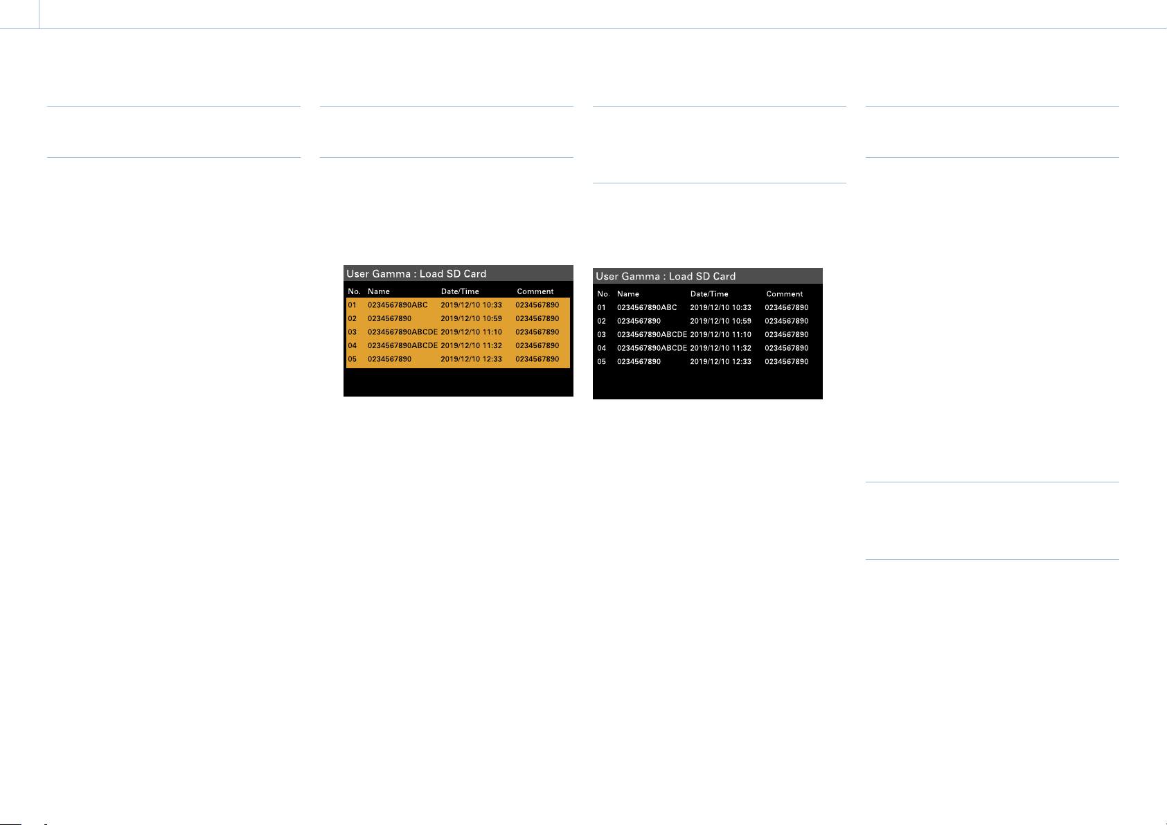
114
6. Saving and Loading User Configuration Data
User Gamma Files
Using User Gamma Files Created
with RAW Viewer V4.0 or Later
You can use user gamma files created with
RAW Viewer V4.0 or later.
Save the created files in the following
directory on an SD card.
MPC-3628:
PRIVATE\SONY\PRO\CAMERA\MPC3628
MPC-3626:
PRIVATE\SONY\PRO\CAMERA\MPC3626
For details about RAW Viewer V4.0 or later,
contact your Sony dealer or a Sony service
representative.
To perform load, check, reset, or other
operations on user gamma files, set Technical
> Special Configuration > RM/RCP Paint
Control (page 91) to On in the full menu to
enable the paint functions.
Loading a User Gamma File from
an SD Card
1 Select Project > User Gamma > Load SD
Card (page 75) in the full menu.
A user gamma file list screen appears.
You can select up to five files on the user
gamma file list screen.
[Note]
The five load operations are performed together.
Files cannot be selected and loaded individually.
2 Press the MENU dial.
A confirmation screen appears.
3 Select Run by turning the MENU dial, then
press the MENU dial.
The five files are loaded into internal
memory.
Checking User Gamma Files
Currently Stored in Internal
Memory
Select Project > User Gamma > Current
Settings (page 74) in the full menu to
display a list of the user gamma files currently
stored in internal memory.
[Note]
Before loading user gamma files from an SD card,
“709(800%)” is displayed under “Name” when Project >
Basic Setting > Input Color Space (page 72) is set to
Rec.709/User Gamma in the full menu. “HLG(Natural)” is
displayed for settings other than Rec.709/User Gamma.
Setting User Gamma Files Stored
in Internal Memory
1 Set Project > Basic Setting > Input Color
Space (page 72) to Rec.2020/User
Gamma or Rec.709/User Gamma in the
full menu.
[Note]
Rec.2020/User Gamma and Rec.709/User Gamma
can be selected only when Technical > Special
Configuration > RM/RCP Paint Control (page 91)
is set to On in the full menu.
2 Select one of User 1 to User 5 in Paint >
Gamma > Gamma Select (page 85) in
the full menu.
[Note]
The User 1 to User 5 options in Gamma Select
correspond to numbers 1 to 5 on the user gamma
file list screen.
Resetting User Gamma Files
Stored in Internal Memory to
Default State
1 Select Project > User Gamma > Reset
(page 75) in the full menu.
A gamma file number reset selection
screen appears.
2 Turn the MENU dial to select the number
of the gamma file to reset (1 to 5).
To reset all gamma files, select All.
A confirmation screen appears.
3 Select Run by turning the MENU dial, then
press the MENU dial.

115
7. Connecting External Devices
Connecting a Remote Control Unit
When an RM-B170 Remote Control Unit,
RCP-1001/1501/3100/3501 Remote Control
Panel, or other control unit is connected, some
functions can be controlled from that unit.
Connecting a Remote Control Unit
Connect the camera connector of the control
unit to the REMOTE connector (8-pin) of the
unit using a remote control cable.
When you turn on the unit after making the
connection, the unit enters remote control
mode, enabling menu operations and
shooting operations.
[Notes]
• Do not connect or disconnect the remote control unit
when the unit is on.
• A remote control cable is not supplied with the RCP-
1001/1501/3100/3501 Remote Control Panel.
Releasing Remote Control Mode
Turn off the unit, and disconnect the remote
control unit.
Setting the Paint Function
Technical > Special Configuration > RM/RCP
Paint Control (page 91) must be set to On in
the full menu to enable the paint function.

7. Connecting External Devices: Connecting a Remote Control Unit
116
Main Functions Controllable using the RCP-1001/1501/3100/3501 or RM-B170/B750
Table legend
The following indicate remote control support on the display.
Yes: Control supported
–: Control not supported
Item Sub-item Sub-item Selection option RCP-1001 RCP-1501/3501 RCP-3100 RM-B170 RM-B750
Shooting FPS Fixed/Variable Select On/Off – Yes – Yes
1)
Yes
FPS Select 1FPS to 120FPS – Yes – Yes
1)
Yes
Shutter Select
2)
Shutter ON/OFF On/Off – Yes Yes Yes Yes
ECS ON/OFF On/Off – Yes Yes Yes Yes
Shutter Speed Values registered for Step.
The following values can be
displayed.
1/32
1/33
1/48
1/50
1/60
1/96
1/100
1/120
1/125
1/250
1/500
1/1000
1/2000
1/3000
1/4000
1/5000
– Yes Yes Yes Yes
ECS Frequency – – Yes Yes Yes Yes
ND ND Position 1: (CLEAR)
2: (0.3 density)
3: (0.6 density)
4: (0.9 density)
5: (1.2 density)
6: (1.5 density)
7: (1.8 density)
8: (2.1 density)
9: (2.4 density)
Yes Yes Yes Yes Yes

7. Connecting External Devices: Connecting a Remote Control Unit
117
Item Sub-item Sub-item Selection option RCP-1001 RCP-1501/3501 RCP-3100 RM-B170 RM-B750
Gain
2)
Gain(Step)
–6dB/–3dB/0dB/3dB/6dB/9dB/
12dB/15dB/18dB
Yes Yes Yes
1)
Yes Yes
White Balance
2)
Color Temp 2000K to 15000K
3)
– Yes Yes
1)
– Yes
Color Temp Balance (Tint
equivalent)
–99 to ±0 to +99
4)
– Yes Yes
1)
– Yes
R Gain –99 to ±0 to +99 Yes Yes – Yes Yes
B Gain –99 to ±0 to +99 Yes Yes – Yes Yes
Auto White Balance – Yes Yes Yes Yes Yes
Project Scene File
2) 5)
– – – Yes Yes – Yes
Standard File
6)
– – Yes Yes – – Yes
Paint
2)
Switch Status Gamma On/Off – Yes Yes
1)
Yes
1)
Yes
Black Gamma
7)
On/Off – Yes Yes
1)
Yes
1)
Yes
Matrix On/Off – Yes Yes
1)
– Yes
Knee
7)
On/Off – Yes Yes
1)
Yes
1)
Yes
White Clip
7)
On/Off – Yes Yes
1)
– Yes
Detail On/Off –
Yes Yes
1)
– Yes
Flare On/Off – Yes Yes Yes
1)
Yes
Test Saw
8)
On/Off – Yes Yes Yes
1)
Yes
Black Master Black –99 to ±0 to +99 Yes Yes Yes Yes Yes
R Black –99 to ±0 to +99 Yes Yes Yes Yes Yes
B Black –99 to ±0 to +99 Yes Yes Yes Yes Yes
Flare Setting On/Off – Yes Yes Yes
1)
Yes
Master Flare –99 to ±0 to +99 – Yes Yes Yes
1)
–
R Flare –99 to ±0 to +99 – Yes Yes – Yes
G Flare –99 to ±0 to +99 – Yes Yes – Yes
B Flare –99 to ±0 to +99 – Yes Yes – Yes
Gamma Setting On/Off – Yes Yes
1)
Yes
1)
Yes
Gamma Category
(display only)
9)
User – Yes – – Yes
Gamma Select User 1/User 2/User 3/User 4/User 5 – Yes – – Yes
Black Gamma
7)
Setting On/Off – Yes Yes
1)
Yes
1)
Yes
Range Low/L.Mid/H.Mid – Yes – – Yes
Master Black Gamma –99 to ±0 to +99 – Yes Yes
1)
Yes
1)
Yes
Knee
7) 10)
Setting On/Off Yes Yes Yes
1)
Yes Yes
Point –99 to ±0 to +99 Yes Yes Yes
1)
Yes Yes
Slope –99 to ±0 to +99 Yes Yes Yes
1)
– Yes

7. Connecting External Devices: Connecting a Remote Control Unit
118
Item Sub-item Sub-item Selection option RCP-1001 RCP-1501/3501 RCP-3100 RM-B170 RM-B750
White Clip
7)
Setting On/Off – Yes Yes
1)
– Yes
Level –99 to ±0 to +99 – Yes – – Yes
Detail Setting On/Off – Yes Yes
1)
– Yes
Level –99 to ±0 to +99 – Yes Yes
1)
– Yes
H/V Ratio –99 to ±0 to +99 – Yes – – Yes
Crispening –99 to ±0 to +99 – Yes – – Yes
Level Depend On/Off – Yes – – Yes
Level Depend Level –99 to ±0 to +99 – Yes – – Yes
Frequency –99 to ±0 to +99 – Yes – – Yes
Knee Aperture On/Off – Yes – – Yes
Knee Aperture Level –99 to ±0 to +99 – Yes – – Yes
Limit –99 to ±0 to +99 – Yes – – Yes
White Limit –99 to ±0 to +99 – Yes – – Yes
Black Limit –99 to ±0 to +99 – Yes – – Yes
Matrix Setting On/Off – Yes Yes
1)
– Yes
User Matrix On/Off – Yes – – Yes
User Matrix R-G –99 to ±0 to +99 – Yes –
– Yes
User Matrix R-B –99 to ±0 to +99 – Yes – – Yes
User Matrix G-R –99 to ±0 to +99 – Yes – – Yes
User Matrix G-B –99 to ±0 to +99 – Yes – – Yes
User Matrix B-R –99 to ±0 to +99 – Yes – – Yes
User Matrix B-G –99 to ±0 to +99 – Yes – – Yes
Multi Matrix Setting On/Off – Yes – – Yes
Area Indication On/Off – Yes – – Yes
Reset Run/Cancel – Yes – – Yes
Axis B/B+/MG–/MG/MG+/R/R+/YL–/YL/
YL+/G–/G/G+/CY/CY+/B–
– Yes – – Yes
Hue –99 to ±0 to +99 – Yes – – Yes
Saturation –99 to ±0 to +99 – Yes – – Yes
Technical Test Signals Color Bars On/Off On/Off Yes Yes Yes Yes Yes
Test Saw
8)
On/Off – Yes Yes Yes
1)
Yes
Rec – – – – – – Yes Yes
Play – – – – – – Yes Yes
Stop – – – – – – Yes Yes
F.Rev – – – – – – Yes
Yes
F.Fwd – – – – – – Yes Yes
Rec Review – – – – – – Yes Yes
Next – – – – – – Yes –

7. Connecting External Devices: Connecting a Remote Control Unit
119
Item Sub-item Sub-item Selection option RCP-1001 RCP-1501/3501 RCP-3100 RM-B170 RM-B750
Prev. – – – – – – Yes –
White Mode
2)
Preset ON/OFF – On/Off – – – Yes Yes
Iris Iris Level – (Control range of target lens) Yes Yes Yes Yes Yes
Close – On/Off Yes Yes Yes – Yes
Zoom
11)
Remote – On/Off – Yes
1)
Yes
1)
Yes
1)
–
Speed – – – – – – –
Tele to Wide – – – Yes
1)
Yes
1)
Yes
1)
–
Zoom Value[%] – – – Yes
1)
Yes
1)
Yes
1)
–
Focal Length[mm] – – – Yes
1)
Yes
1)
Yes
1)
–
Focus
11)
Remote – On/Off – Yes
1)
Yes
1)
Yes
1)
–
Focus Position – – – Yes
1)
Yes
1)
Yes
1)
–
Focus Value[%] – – – Yes
1)
Yes
1)
Yes
1)
–
Focus Length[m] – – – Yes
1)
Yes
1)
Yes
1)
–
Call – – – Yes Yes Yes Yes Yes
1) Controllable when assigned to operation block of controller.
2) Controllable only when Technical > Special Configuration > RM/RCP Paint Control (page 91) is set to On in the full menu.
3) Since Color Temp is clipped at 2000K and 15000K during R/B Gain operation, it may not be possible to display the correct Color Temp value for the R/B Gain value.
4) Since Color Temp Balance is clipped at ±99, it may not be possible to display the correct Color Temp Balance value for the R/B Gain value.
5) Scene files 1 to 5 can be selected or deselected only after they have been loaded into the unit.
6) Allows you to restore the settings of the unit to standard state from the controller without any scene files loaded.
7) Configurable only when Project > Basic Setting > Input Color Space (page 72) is set to HLG(Natural), HLG(Live), Rec.2020/User Gamma, or Rec.709/User Gamma in the full menu.
8) The test signal cannot be switched on/of during auto white balance execution.
9) May not be displayed depending on the controller model and version.
10) The normal Knee function of the unit controls the high-luminance knee equivalent of HDR Knee.
11) The zoom and focus drive instructions from a remote control unit are disabled when an E-mount lens is attached.

120
7. Connecting External Devices
Connecting External Monitors and Recording Devices
To display the recording/playback image on
an external monitor, select the output signal
and use an appropriate cable for the monitor
to be connected.
The output signal from the unit can be
recorded by connecting a recording device,
such as a VTR.
The same status information and menus can
be displayed on the external monitor as those
on the viewfinder screen. Set the content
to display, according to the output signal
for the monitor, using the Monitoring menu
(page 77).
[Note]
When FPS is set to Variable, horizontal image shift may
occur with 4K output only. This phenomenon may be
noticeable for faster frame rates (FPS). However, this
does not affect the recorded image, and the playback
image is displayed correctly.
SDI OUT Connector (BNC Type)
Set the output format using the Monitoring
menu
(page 77)
.
Use a commercially available 75-ohm coaxial
cable for connection.
[Note]
Check that the ground connection between the unit
and external device is securely grounded before turning
the power on. (We recommend turning on the unit and
external device after connecting a 75-ohm coaxial cable.)
When connecting an external device to the unit
while the unit is turned on, connect to the unit after
connecting a 75-ohm coaxial cable to the external
device.
To start synchronized recording on an
external device
With SDI signal output selected, synchronized
recording is possible by feeding a REC
trigger signal to an external recording device
connected to the SDI OUT connector. Enable
synchronized recording by setting Technical
> System Configuration > SDI Rec Remote
Trigger (page 87) in the menu to HD SDI
Remote I/F or Parallel Rec.
[Notes]
• If a connected external device does not support a REC
trigger signal, the device cannot be operated.
• When outputting a monitor signal on SDI 3/4, the REC
trigger signal is not output.
• When SDI 1/2 output is the following, the monitor
signal is output on SDI 3/4.
– 4K/QFHD 12G/6G output
– 4K/QFHD Dual output
MONITOR OUT Connector (BNC
Type)
Outputs an HD SDI signal.
Set the output format using the Monitoring
menu (page 77).
Use a commercially available 75-ohm coaxial
cable for connection.
[Note]
Audio and timecode are not superimposed on this
output.
HDMI OUT Connector (Type A
Connector)
Set the output format using the Monitoring
menu (page 77).
Use a commercially available HDMI cable for
connection.
If the output format has the same resolution
as the MONITOR OUT connector signal, the
same video signal is output.
12V OUT Connector (12 V DC
Output, LEMO 2-pin)
Supplies 12 V DC power to an accessory when
the power switch is set to ON.
No. Signal I/O Specification
1 UNREG GND – GND
2 UNREG +12 V
OUT
OUT +11V to +17V DC
output
11 V to 17 V input
Output voltage:
Same as the input
voltage
Maximum output
current: 1.0A
22 V to 32 V input
Output voltage:
16.8V
Maximum output
current: 1.0A
24V OUT Connector (24 V DC
Output, Fischer 3-pin)
Supplies 24V DC power to an accessory when
the power switch is set to ON. You can input
a REC Trigger signal through the 24V OUT
connector.
No. Signal Specification
1 GND
2 24V-OUT
11 V to 17 V input
Output voltage: 24 V
Maximum output
current: 1.0 A
22 V to 32 V input
Output voltage: Same as
the input voltage
Maximum output
current: 2.0 A
3 REC
TRIGGER IN
Open or +5V DC: Normal
GND: Active (REC)
AUX connector (BNC Type)
Outputs the timecode signal or a clock
signal for adjustment during manufacturing/
servicing.
• TC OUT
• Factory Use
Use a commercially available 75-ohm coaxial
cable for connection.
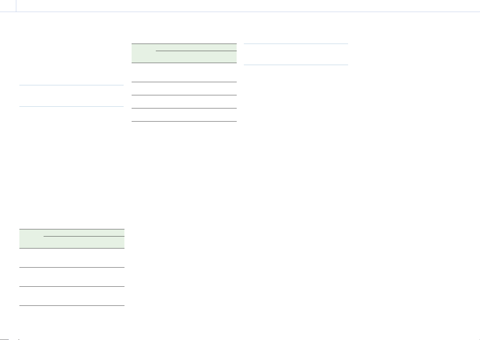
121
7. Connecting External Devices
When shooting with multiple units,
synchronized recording can be performed
using a specific reference signal to
synchronize the timecode among all the units.
Synchronizing the Phase of the
Video Signal (Genlock)
Genlock operation is enabled by supplying
one of the following reference signals to the
GENLOCK IN connector (page 12) of the
unit.
• HDSDI 1.5G digital (Interlaced/PsF/
Progressive)
• HD Y analog (Interlaced/Progressive)
• SD VBS analog
Set the genlock input signal using TC/Media >
Genlock > Input Source (page 76) in the full
menu.
You can also check the genlock status using
TC/Media > Genlock > Reference Lock Type
(page 76) in the full menu, the Home
screen of the sub display (page 36), and the
genlock status indicator (page 14).
Valid input reference signals vary depending
on the project frame rate setting.
Project
frame
rate
Valid reference signal
Analog Digital
23.98 1920×1080 47.95i
(23.98PsF)
1920×1080 23.98P
1920×1080
23.98PsF
1920×1080 23.98P
24 1920×1080 48i
(24PsF)
1920×1080 24P
1920×1080 24PsF
1920×1080 24P
25 1920×1080 50i
720×576 50i
1920×1080 25P
1920×1080 50i
1920×1080 25PsF
1920×1080 25P
Project
frame
rate
Valid reference signal
Analog Digital
29.97 1920×1080 59.94i
720×486 59.94i
1920×1080 29.97P
1920×1080 59.94i
1920×1080 29.97PsF
1920×1080 29.97P
47.95 1920×1080 47.95i
(23.98PsF)
1920×1080
23.98PsF
50 1920×1080 50i
720×576 50i
1920×1080 50i
59.94 1920×1080 59.94i
720×486 59.94i
1920×1080 59.94i
You can check the genlock status using TC/
Media > Genlock > Reference Lock Type
(page 76) in the menu.
[Notes]
• If the reference signal is unstable, genlock is not
possible.
• The subcarrier is not synchronized.
Synchronizing the Timecode with
Another Device
Set the unit that supplies the timecode to a
mode in which the timecode output keeps
advancing (Free Run mode).
1 Set TC/Media > Timecode > Mode
(page 76) in the menu to Preset F-Run
(Ext-Lk).
2 Supply an HD or SD reference video signal
to the GENLOCK IN connector (page 12)
and a reference timecode synchronized
with that signal to the TC IN (page 12)
connector.
The built-in timecode generator of your unit
locks to the reference timecode, and the
message “Ext-Lk” is displayed on the Home
screen of the sub display.
Once about ten seconds have elapsed after
the timecode locks, the external lock state
is maintained even if the external timecode
source is disconnected.
[Notes]
• Check that the reference timecode and the reference
video signal are in a phase relationship that complies
with the SMPTE timecode standards.
• When you finish the above procedure, the timecode
is immediately synchronized with the external
timecode, and the time data indication will show the
value of the external timecode. However, wait for a
few seconds until the timecode generator stabilizes
before recording.
• If the frequency of the reference video signal and the
frame frequency are not the same, lock cannot be
acquired, and the unit will not operate properly. If this
occurs, the timecode will not acquire successful lock
with the external timecode.
• When the connection is removed, the timecode
advance may shift one frame per hour with respect to
the reference timecode.
To release external lock
Change the TC/Media > Timecode > Mode
(page 76) setting in the menu.
External Synchronization

122
8. Appendix
Usage Precautions
Read this section in conjunction with the
information provided in the supplied “Before
Using This Unit” document.
Use and Storage
Do not subject the unit to severe shock
The internal mechanism may be damaged or
the body warped.
Do not cover the unit while operating
Putting a cloth, for example, over the unit can
cause excessive internal heat build-up.
After use
Always set the power switch to OFF.
Before storing the unit for a long period
Remove the battery pack.
Do not leave the unit with the lens
facing the sun
Direct sunlight can enter through the lens, be
focused in the unit, and cause fire.
Shipping
• Remove the memory cards before
transporting the unit.
• If sending the unit by truck, ship, air or
other transportation service, pack it in the
shipping carton of the unit.
Care of the Unit
If the body of the unit is dirty, clean it with a
soft, dry cloth. In extreme cases, use a cloth
moistened in a little neutral detergent, then
wipe dry.
Do not use organic solvents, such as alcohol or
thinners, as these may cause discoloration or
other damage to the finish of the unit.
Refrain from cleaning with high air pressure
equipment, such as an air duster, as these
may damage optical components.
In the event of operating problems
If you should experience problems with the
unit, contact your Sony dealer.
Periodic Replacement of Fan and
Battery
The fan and battery are consumable parts that
will need periodic replacement.
When operating at room temperature, a
normal replacement cycle will be about
5 years. However, this replacement cycle
represents only a general guideline and does
not imply that the life expectancy of these
parts is guaranteed. For details on parts
replacement, contact your dealer.
Life Expectancy of the Electrolytic
Capacitor
The life expectancy of the electrolytic
capacitor is about 5 years under normal
operating temperatures and normal usage (8
hours per day; 25 days per month).
If usage exceeds the above normal usage
frequency, the life expectancy may be reduced
correspondingly.
Note about the Battery Terminal
The battery terminal of this unit (the connector
for battery packs and AC adaptors) is a
consumable part.
Power may not be supplied to the unit
properly if the pins of the battery terminal are
bent or deformed by shock or vibrations, or
if they become corroded due to prolonged
outdoor use.
Periodic inspections are recommended to
keep the unit working properly and to prolong
its usable lifetime. Contact a Sony service or
sales representative for more information
about inspections.
Use and Storage Locations
Store in a level, ventilated place.
Avoid using or storing the unit in the following
places.
• In excessive heat or cold (operating
temperature range: 0 °C to 40 °C (32 °F to
104 °F))
Remember that in summer in warm climates
the temperature inside a car with the
windows closed can easily exceed 50 °C (122
°F).
• In damp or dusty locations
• Locations where the unit may be exposed
to rain
• Locations subject to violent vibration
• Near strong magnetic fields
• Close to radio or TV transmitters producing
strong electromagnetic fields.
• In direct sunlight or close to heaters for
extended periods
To prevent electromagnetic interference
from portable communications devices
The use of portable telephones and other
communications devices near this unit can
result in malfunctions and interference with
audio and video signals.
It is recommended that the portable
communications devices near this unit be
powered off.
Note on laser beams
Laser beams may damage the CMOS image
sensor. If you shoot a scene that includes
a laser beam, be careful not to let the laser
beam be directed into the lens of the unit.
Specifically, high-power laser beams from
medical devices or other devices may cause
damage due to reflected light and scattered
light.
About the Screens
• Do not leave the screens facing direct
sunlight, as this may damage the screens.
• Do not press/swipe the screens forcefully,
or leave objects on the screens, as it may
cause a malfunction, such as picture
irregularity, etc.
• The screens may become warm in use. This
is not a malfunction.

8. Appendix: Usage Precautions
123
LCD Panels
The LCD panel fitted to this unit is
manufactured with high precision technology,
giving a functioning pixel ratio of at least
99.99%. Thus a very small proportion of pixels
may be “stuck”, either always off (black),
always on (red, green, or blue), or flashing. In
addition, over a long period of use, because
of the physical characteristics of the liquid
crystal display, such “stuck” pixels may appear
spontaneously.
These problems are not a malfunction.
Note that any such problems have no effect
on recorded data.
OLED Panels
The OLED panel fitted to this unit is
manufactured with high precision technology,
giving a functioning pixel ratio of at least
99.99%. Thus a very small proportion of pixels
may be “stuck”, either always off (black),
always on, or flashing. In addition, over a
long period of use, because of the physical
characteristics of the organic light-emitting
diode, such “stuck” pixels may appear
spontaneously. These problems are not a
malfunction. Note that any such problems
have no effect on recorded data.
Due to the characteristics of the material used
in the OLED panel, permanent burn-in or
reduction in brightness may occur.
These problems are not a malfunction.
On Condensation
If the unit is suddenly taken from a cold to
a warm location, or if ambient temperature
suddenly rises, moisture may form on the
outer surface of the unit and/or inside of
the unit. This is known as condensation. If
condensation occurs, turn off the unit and
wait until the condensation clears before
operating the unit. Operating the unit while
condensation is present may damage the unit.
Phenomena Specific to CMOS
Image Sensors
The following phenomena that may appear in
images are specific to CMOS (Complementary
Metal Oxide Semiconductor) image sensors.
They do not indicate malfunctions.
White flecks
Although the CMOS image sensors are
produced with high-precision technologies,
fine white flecks may be generated on the
screen in rare cases, caused by cosmic rays,
etc. This is related to the principle of image
sensors and is not a malfunction.
The white flecks especially tend to be seen in
the following cases.
• When operating at high environmental
temperatures
Aliasing
When fine patterns, stripes, or lines are shot,
they may appear jagged or flicker.
Focal plane
Owing to the characteristics of the pickup
elements (CMOS sensors) for reading video
signals, subjects that quickly move across the
screen may appear slightly skewed.
Flashbanding
The luminance at the top and bottom of the
screen may change when shooting a flashlight
beam or a light source that quickly flashes.
Flicker
If recording is made under lighting produced
by discharge tubes, such as fluorescent,
sodium, or mercury-vapor lamps, the screen
may flicker, colors may vary, or horizontal
stripes may appear distorted.
The flicker can be reduced using the flicker
reduction function of the unit (page 65).
Notes on the Display
• Pictures on the viewfinder screen and
outputs may be distorted by the following
operations.
– Changing the video format
– Changing the FPS frame rate
– When genlock is applied
• When you change the line of sight in the
viewfinder, you may see primary colors red,
green, and blue, but this is not a defect
of the unit. These primary colors are not
recorded on any recording media.
Fragmentation
If pictures cannot be recorded/reproduced
properly, try formatting the recording
medium. While repeating picture recording/
playback with a certain recording media for
an extended period, files in the media may
be fragmented, disabling proper recording/
storage. In such a case, make a backup of
clips in the media then perform formatting
of the media using TC/Media > Format Media
(page 76) in the menu.

8. Appendix: Usage Precautions
124
Output Voltages of the Unit
The total output power that can be supplied
to peripheral devices from the unit varies
depending on the input voltage to the unit
and the state of the connected accessories.
The maximum output capacity ratings of the
following connectors that can supply power
may not be achieved depending on the
conditions.
LENS connector: 1 A max.
12V OUT connector (2-pin): 1 A max.
24V OUT connector (3-pin):
2 A max. (Input voltage: 22 V to 32 V)
1 A max. (Input voltage: 11 V to 17 V)
The power delivery rating available for
accessories (DVF-EL200 and CBK-3610XS) and
peripheral devices is limited depending on the
input voltage to the unit.
Voltage of power supply to the unit: X[V]
Total power rating of peripheral devices:
Y[W]
Power consumption of the unit: Z[W]
1)
Power consumption of the DVF-EL200:
Approx. 2.5 W
Power consumption of the CBK-3610XS:
Approx. 3.9 W
Y [W] = X [V] × 9.0 [A]
*
– (Z + + ) [W]
* If X [V] × 9.0 [A] exceeds 220 [W], perform the
calculation using 220 [W].
When supplying power to the above attached
accessories and peripheral devices, make sure
that the value Y given by the equation above
does not become negative. It is recommended
that the maximum power consumption value
of the unit be used for the power consumption
of the unit.
1)
(Note that the equation does not apply if the
calculated result Y exceeds the sum of the
maximum allowable output power of each
power output connector.)
1) MPC-3628:
Unit nominal power consumption: Approx. 76W (8.6K
3:2, 24 FPS, X-OCN XT recording)
Unit maximum power consumption: Approx. 100W
(8.2K 17:9, 60 FPS, X-OCN ST recording, 40°C (104°F)
environment, 32V DC input)
MPC-3626:
Unit nominal power consumption: Approx. 73W (6K
3:2, 24 FPS, X-OCN XT recording)
Unit maximum power consumption: Approx. 94W
(6K 3:2, 60 FPS, X-OCN ST recording, 40°C (104°F)
environment, 32V DC input)
Notes on Security
• SONY WILL NOT BE LIABLE FOR DAMAGES
OF ANY KIND RESULTING FROM A FAILURE
TO IMPLEMENT PROPER SECURITY
MEASURES ON TRANSMISSION DEVICES,
UNAVOIDABLE DATA LEAKS RESULTING
FROM TRANSMISSION SPECIFICATIONS, OR
SECURITY PROBLEMS OF ANY KIND.
• Depending on the operating environment,
unauthorized third parties on the network
may be able to access the unit. When
connecting the unit to the network, be sure
to confirm that the network is protected
securely.
• From a safety standpoint, when using
the unit connected with the network, it
is strongly recommended to access the
Control window via a Web browser and
change the access limitation settings from
the factory preset values (page 87).
Changing the password regularly is also
recommended.
• Do not browse any other website in the
Web browser while making settings or after
making settings. Since the login status
remains in the Web browser, close the Web
browser when you complete the settings
to prevent unauthorized third parties from
using the unit or harmful programs from
running.
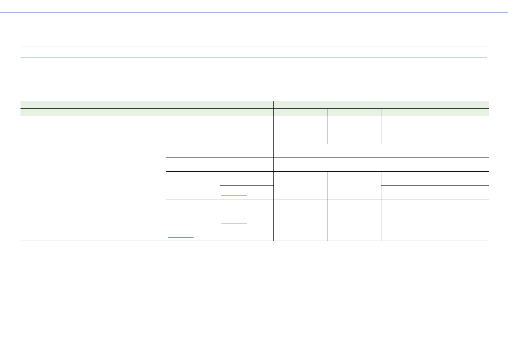
125
8. Appendix
SDI OUT Connector Output Formats
The serial digital signal from an SDI OUT connector is output according to the Project category and Monitoring category settings in the menu.
For details about Project category settings combinations, see “Recording Format Settings” (page 59).
You can set the 3G SDI output format to Level A or Level B using Monitoring > Output Format > 3G SDI 1/2/3/4 Output (page 77) in the full menu.
Default values are shown underlined and in
bold text.
Project Monitoring > Output Format Output format
Project Frame Rate Imager Mode Recording Format SDI 1/2 SDI 3/4 SDI 1 SDI 2 SDI 3 SDI 4
59.94/50 8.2K 17:9/
6K 3:2/
6K 1.85:1/
6K 17:9/
6K 2.39:1/
5.8K 6:5/
5.8K 17:9/
4K 6:5/
4K 4:3/
4K 17:9/
4K 2.39:1
X-OCN XT
X-OCN ST
X-OCN LT
ProRes 4444 4K
ProRes 422 HQ 4K
4096×2160P 12G
1920×1080P Level A
1)
4096×2160P
YPbPr 12G
4096×2160P
YPbPr 12G
1920×1080P
YPbPr 3G Level A
1920×1080P
YPbPr 3G Level A
1920×1080i
1920×1080i
YPbPr 1.5G
1920×1080i
YPbPr 1.5G
4096×2160P
Square Level B
2)
4096×2160P
Square Level B
2)
4096×2160P YPbPr 3G Square Level B
4096×2160P
2SI Level B
2)
4096×2160P
2SI Level B
2)
4096×2160P YPbPr 3G 2SI Level B
2048×1080P Level B
2)
1920×1080P Level B
2)
2048×1080P
YPbPr 3G Level B
2048×1080P
YPbPr 3G Level B
1920×1080P
YPbPr 3G Level B
1920×1080P
YPbPr 3G Level B
1920×1080i
1920×1080i
YPbPr 1.5G
1920×1080i
YPbPr 1.5G
1920×1080P Level B
2)
1920×1080P Level B
2)
1920×1080P
YPbPr 3G Level B
1920×1080P
YPbPr 3G Level B
1920×1080P
YPbPr 3G Level B
1920×1080P
YPbPr 3G Level B
1920×1080i
1920×1080i
YPbPr 1.5G
1920×1080i
YPbPr 1.5G
1920×1080i
1920×1080i
1920×1080i
YPbPr 1.5G
1920×1080i
YPbPr 1.5G
1920×1080i
YPbPr 1.5G
1920×1080i
YPbPr 1.5G
Recording Formats and Output Signals
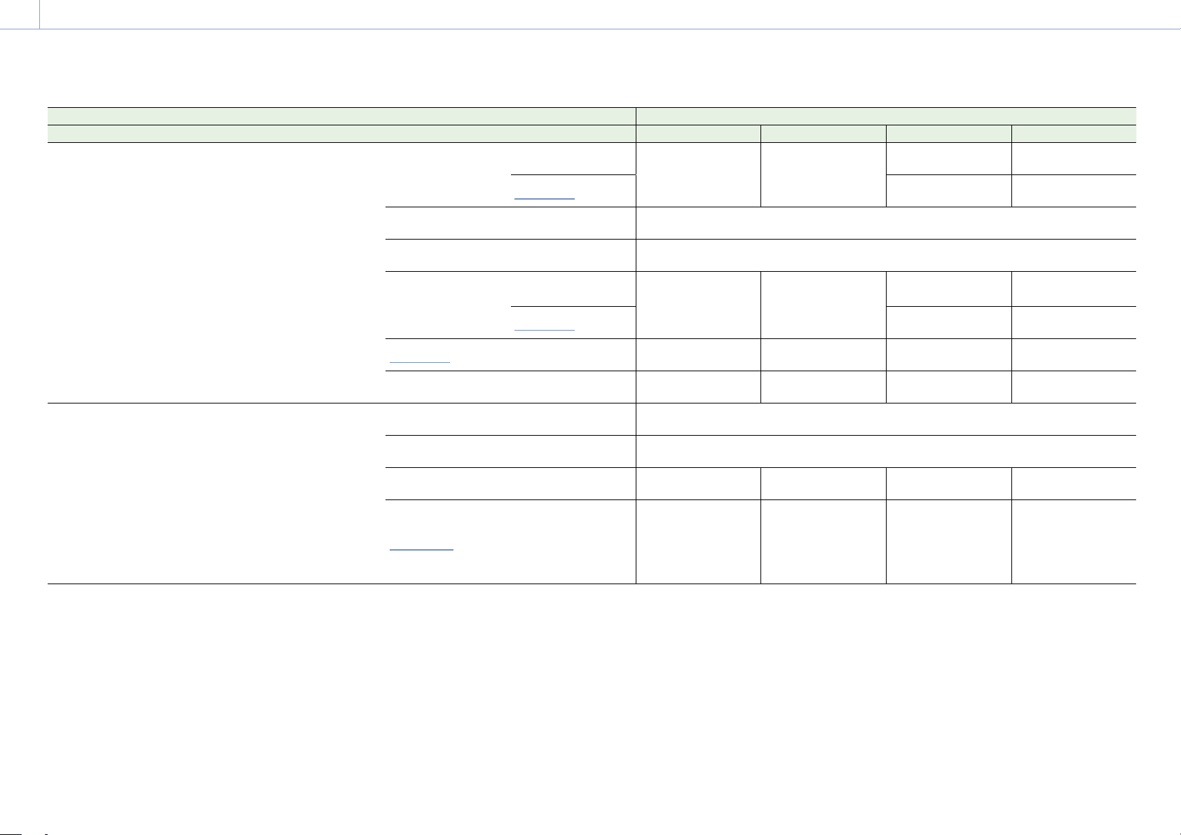
8. Appendix: Recording Formats and Output Signals
126
Project Monitoring > Output Format Output format
Project Frame Rate Imager Mode Recording Format SDI 1/2 SDI 3/4 SDI 1 SDI 2 SDI 3 SDI 4
59.94/50 7.6K 16:9/
5.7K 16:9/
5.4K 16:9/
3.8K 16:9
X-OCN XT
X-OCN ST
X-OCN LT
ProRes 4444 QFHD
ProRes 422 HQ QFHD
3840×2160P 12G
1920×1080P Level A
1)
3840×2160P
YPbPr 12G
3840×2160P
YPbPr 12G
1920×1080P
YPbPr 3G Level A
1920×1080P
YPbPr 3G Level A
1920×1080i
1920×1080i
YPbPr 1.5G
1920×1080i
YPbPr 1.5G
3840×2160P
Square Level B
2)
3840×2160P
Square Level B
2)
3840×2160P YPbPr 3G Square Level B
3840×2160P
2SI Level B
2)
3840×2160P
2SI Level B
2)
3840×2160P YPbPr 3G 2SI Level B
1920×1080P Level B
2)
1920×1080P Level B
2)
1920×1080P
YPbPr 3G Level B
1920×1080P
YPbPr 3G Level B
1920×1080P
YPbPr 3G Level B
1920×1080P
YPbPr 3G Level B
1920×1080i
1920×1080i
YPbPr 1.5G
1920×1080i
YPbPr 1.5G
1920×1080i
1920×1080i
1920×1080i
YPbPr 1.5G
1920×1080i
YPbPr 1.5G
1920×1080i
YPbPr 1.5G
1920×1080i
YPbPr 1.5G
1920×1080i
3)
1920×1080i
3)
1920×1080i
YPbPr 1.5G
1920×1080i
YPbPr 1.5G
1920×1080i
YPbPr 1.5G
1920×1080i
YPbPr 1.5G
47.95 8.2K 17:9/
6K 3:2/
6K 1.85:1/
6K 17:9/
6K 2.39:1/
5.8K 6:5/
5.8K 17:9/
4K 6:5/
4K 4:3/
4K 17:9/
4K 2.39:1
3.8K 16:9
X-OCN XT
X-OCN ST
X-OCN LT
4096×2160P
Square Level B
2)
4096×2160P
Square Level B
2)
4096×2160P YPbPr 3G Square Level B
4096×2160P
2SI Level B
2)
4096×2160P
2SI Level B
2)
4096×2160P YPbPr 3G 2SI Level B
2048×1080P Level B
2)
1920×1080P
2048×1080P
YPbPr 3G Level B
2048×1080P
YPbPr 3G Level B
1920×1080P
YPbPr 1.5G
1920×1080P
YPbPr 1.5G
1920×1080P
1920×1080P
1920×1080P
YPbPr 1.5G
1920×1080P
YPbPr 1.5G
1920×1080P
YPbPr 1.5G
1920×1080P
YPbPr 1.5G

8. Appendix: Recording Formats and Output Signals
127
Project Monitoring > Output Format Output format
Project Frame Rate Imager Mode Recording Format SDI 1/2 SDI 3/4 SDI 1 SDI 2 SDI 3 SDI 4
29.97/25 8.6K 3:2/
8.2K 17:9/
6K 3:2/
6K 1.85:1/
6K 17:9/
6K 2.39:1/
5.8K 6:5/
5.8K 17:9/
4K 6:5/
4K 4:3/
4K 17:9/
4K 2.39:1
X-OCN XT
X-OCN ST
X-OCN LT
ProRes 4444 4K
ProRes 422 HQ 4K
4096×2160P 6G
1920×1080P
4096×2160P
YPbPr 6G 2SI
4096×2160P
YPbPr 6G 2SI
1920×1080P
YPbPr 1.5G
1920×1080P
YPbPr 1.5G
1920×1080PsF
1920×1080PsF
YPbPr 1.5G
1920×1080PsF
YPbPr 1.5G
4096×2160P Square 4096×2160P Square 4096×2160P YPbPr 1.5G Square
4096×2160P 2SI
1920×1080P
4096×2160P YPbPr 3G 2SI
1920×1080P
YPbPr 1.5G
1920×1080P
YPbPr 1.5G
1920×1080PsF
1920×1080PsF
YPbPr 1.5G
1920×1080PsF
YPbPr 1.5G
2048×1080PsF
1920×1080P
2048×1080PsF
YPbPr 1.5G
2048×1080PsF
YPbPr 1.5G
1920×1080P
YPbPr 1.5G
1920×1080P
YPbPr 1.5G
1920×1080PsF
1920×1080PsF
YPbPr 1.5G
1920×1080PsF
YPbPr 1.5G
1920×1080P 1920×1080P
1920×1080P
YPbPr 1.5G
1920×1080P
YPbPr 1.5G
1920×1080P
YPbPr 1.5G
1920×1080P
YPbPr 1.5G
1920×1080PsF
1920×1080PsF
1920×1080PsF
YPbPr 1.5G
1920×1080PsF
YPbPr 1.5G
1920×1080PsF
YPbPr 1.5G
1920×1080PsF
YPbPr 1.5G
7.6K 16:9/
5.7K 16:9/
5.4K 16:9/
3.8K 16:9
X-OCN XT
X-OCN ST
X-OCN LT
ProRes 4444 QFHD
ProRes 422 QFHD
3840×2160P 6G
1920×1080P
3840×2160P
YPbPr 6G 2SI
3840×2160P
YPbPr 6G 2SI
1920×1080P
YPbPr 1.5G
1920×1080P
YPbPr 1.5G
1920×1080PsF
1920×1080PsF
YPbPr 1.5G
1920×1080PsF
YPbPr 1.5G
3840×2160P Square 3840×2160P Square 3840×2160P YPbPr 1.5G Square
3840×2160P 2SI
1920×1080P
3840×2160P YPbPr 3G 2SI
1920×1080P
YPbPr 1.5G
1920×1080P
YPbPr 1.5G
1920×1080PsF
1920×1080PsF
YPbPr 1.5G
1920×1080PsF
YPbPr 1.5G
1920×1080P 1920×1080P
1920×1080P
YPbPr 1.5G
1920×1080P
YPbPr 1.5G
1920×1080P
YPbPr 1.5G
1920×1080P
YPbPr 1.5G
1920×1080PsF
1920×1080PsF
1920×1080PsF
YPbPr 1.5G
1920×1080PsF
YPbPr 1.5G
1920×1080PsF
YPbPr 1.5G
1920×1080PsF
YPbPr 1.5G
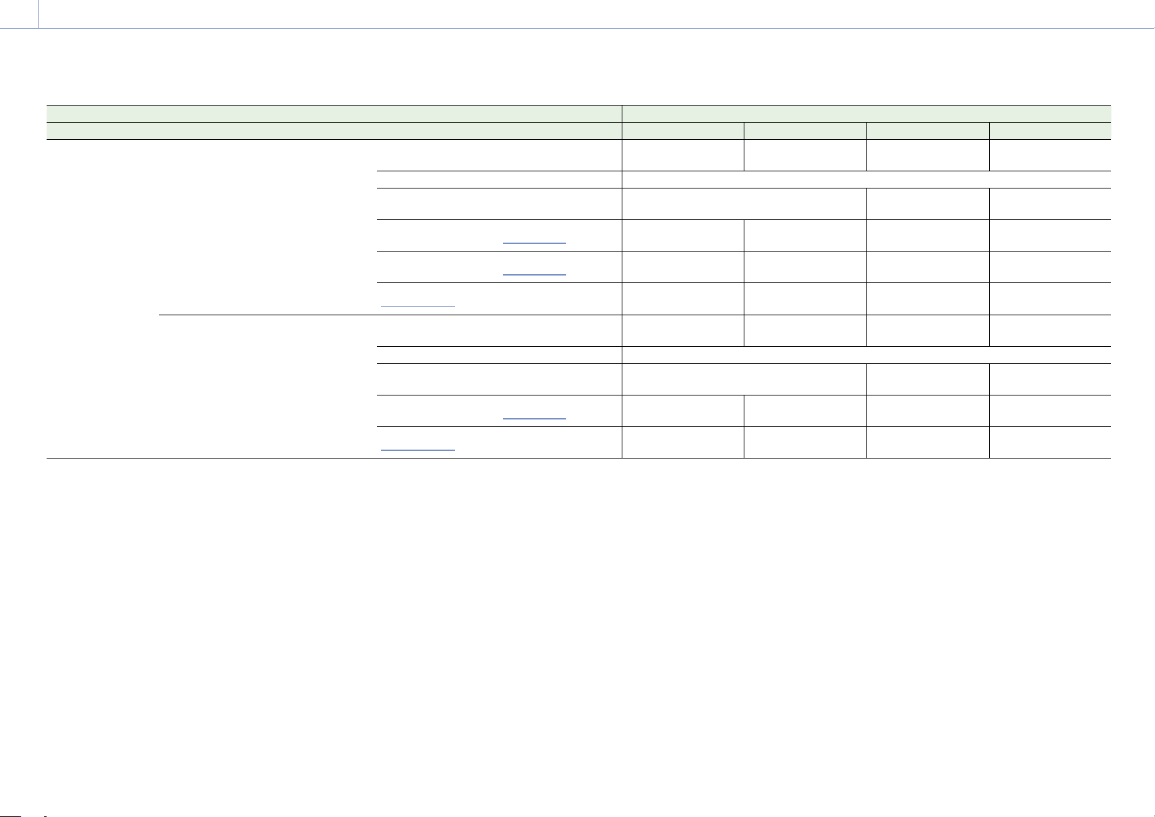
8. Appendix: Recording Formats and Output Signals
128
Project Monitoring > Output Format Output format
Project Frame Rate Imager Mode Recording Format SDI 1/2 SDI 3/4 SDI 1 SDI 2 SDI 3 SDI 4
24 8.6K 3:2/
8.2K 17:9/
6K 3:2/
6K 1.85:1/
6K 17:9/
6K 2.39:1/
5.8K 6:5/
5.8K 17:9/
4K 6:5/
4K 4:3/
4K 17:9/
4K 2.39:1
X-OCN XT
X-OCN ST
X-OCN LT
ProRes 4444 4K
ProRes 422 HQ 4K
4096×2160P 6G 1920×1080P
4096×2160P
YPbPr 6G 2SI
4096×2160P
YPbPr 6G 2SI
1920×1080P
YPbPr 1.5G
1920×1080P
YPbPr 1.5G
4096×2160P Square 4096×2160P Square 4096×2160P YPbPr 1.5G Square
4096×2160P 2SI 1920×1080P 4096×2160P YPbPr 3G 2SI
1920×1080P
YPbPr 1.5G
1920×1080P
YPbPr 1.5G
2048×1080PsF
1920×1080P
2048×1080PsF
YPbPr 1.5G
2048×1080PsF
YPbPr 1.5G
1920×1080P
YPbPr 1.5G
1920×1080P
YPbPr 1.5G
1920×1080P
1920×1080P
1920×1080P
YPbPr 1.5G
1920×1080P
YPbPr 1.5G
1920×1080P
YPbPr 1.5G
1920×1080P
YPbPr 1.5G
1920×1080PsF
1920×1080P
1920×1080PsF
YPbPr 1.5G
1920×1080PsF
YPbPr 1.5G
1920×1080P
YPbPr 1.5G
1920×1080P
YPbPr 1.5G
7.6K 16:9/
5.7K 16:9/
5.4K 16:9/
3.8K 16:9
X-OCN XT
X-OCN ST
X-OCN LT
ProRes 4444 QFHD
ProRes 422 QFHD
3840×2160P 6G 1920×1080P
3840×2160P
YPbPr 6G 2SI
3840×2160P
YPbPr 6G 2SI
1920×1080P
YPbPr 1.5G
1920×1080P
YPbPr 1.5G
3840×2160P Square 3840×2160P Square 3840×2160P YPbPr 1.5G Square
3840×2160P 2SI 1920×1080P 3840×2160P YPbPr 3G 2SI
1920×1080P
YPbPr 1.5G
1920×1080P
YPbPr 1.5G
1920×1080P
1920×1080P
1920×1080P
YPbPr 1.5G
1920×1080P
YPbPr 1.5G
1920×1080P
YPbPr 1.5G
1920×1080P
YPbPr 1.5G
1920×1080PsF
1920×1080P
1920×1080PsF
YPbPr 1.5G
1920×1080PsF
YPbPr 1.5G
1920×1080P
YPbPr 1.5G
1920×1080P
YPbPr 1.5G
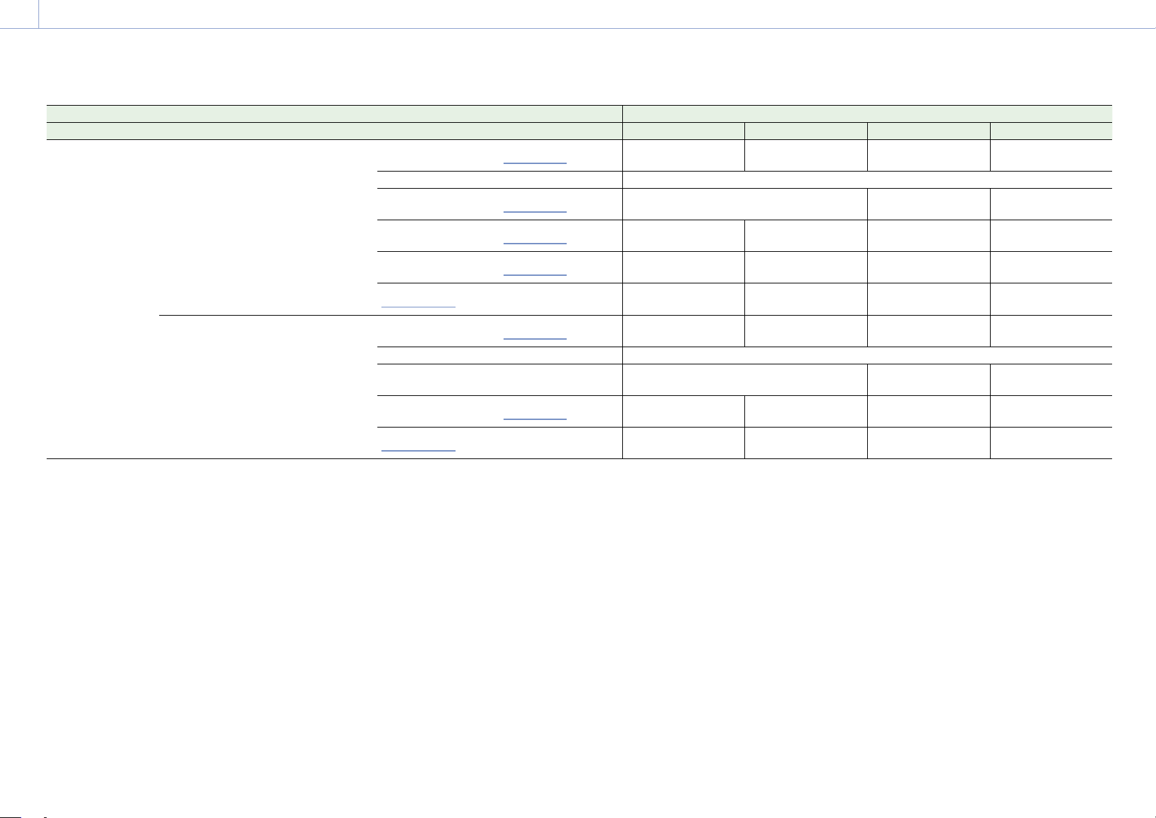
8. Appendix: Recording Formats and Output Signals
129
Project Monitoring > Output Format Output format
Project Frame Rate Imager Mode Recording Format SDI 1/2 SDI 3/4 SDI 1 SDI 2 SDI 3 SDI 4
23.98 8.6K 3:2/
8.2K 17:9/
6K 3:2/
6K 1.85:1/
6K 17:9/
6K 2.39:1/
5.8K 6:5/
5.8K 17:9/
4K 6:5/
4K 4:3/
4K 17:9/
4K 2.39:1
X-OCN XT
X-OCN ST
X-OCN LT
ProRes 4444 4K
ProRes 422 HQ 4K
4096×2160P 6G
1920×1080P
4096×2160P
YPbPr 6G 2SI
4096×2160P
YPbPr 6G 2SI
1920×1080P
YPbPr 1.5G
1920×1080P
YPbPr 1.5G
4096×2160P Square 4096×2160P Square 4096×2160P YPbPr 1.5G Square
4096×2160P 2SI
1920×1080P
4096×2160P YPbPr 3G 2SI
1920×1080P
YPbPr 1.5G
1920×1080P
YPbPr 1.5G
2048×1080PsF
1920×1080P
2048×1080PsF
YPbPr 1.5G
2048×1080PsF
YPbPr 1.5G
1920×1080P
YPbPr 1.5G
1920×1080P
YPbPr 1.5G
1920×1080P
1920×1080P
1920×1080P
YPbPr 1.5G
1920×1080P
YPbPr 1.5G
1920×1080P
YPbPr 1.5G
1920×1080P
YPbPr 1.5G
1920×1080PsF
1920×1080P
1920×1080PsF
YPbPr 1.5G
1920×1080PsF
YPbPr 1.5G
1920×1080P
YPbPr 1.5G
1920×1080P
YPbPr 1.5G
7.6K 16:9/
5.7K 16:9/
5.4K 16:9/
3.8K 16:9
X-OCN XT
X-OCN ST
X-OCN LT
ProRes 4444 QFHD
ProRes 422 QFHD
3840×2160P 6G
1920×1080P
3840×2160P
YPbPr 6G 2SI
3840×2160P
YPbPr 6G 2SI
1920×1080P
YPbPr 1.5G
1920×1080P
YPbPr 1.5G
3840×2160P Square 3840×2160P Square 3840×2160P YPbPr 1.5G Square
3840×2160P 2SI 1920×1080P 3840×2160P YPbPr 3G 2SI
1920×1080P
YPbPr 1.5G
1920×1080P
YPbPr 1.5G
1920×1080P
1920×1080P
1920×1080P
YPbPr 1.5G
1920×1080P
YPbPr 1.5G
1920×1080P
YPbPr 1.5G
1920×1080P
YPbPr 1.5G
1920×1080PsF
1920×1080P
1920×1080PsF
YPbPr 1.5G
1920×1080PsF
YPbPr 1.5G
1920×1080P
YPbPr 1.5G
1920×1080P
YPbPr 1.5G
1) The Level A signal is output even when Monitoring > Output Format > 3G SDI 1/2/3/4 Output (page 77) is set to Level B in the full menu.
2) The menu setting changes to Level A and the Level A signal is output when Monitoring > Output Format > 3G SDI 1/2/3/4 Output is set to Level A in the full menu.
3) Set when Technical > Special Configuration > SD HDMI (page 91) is set to On in the full menu.
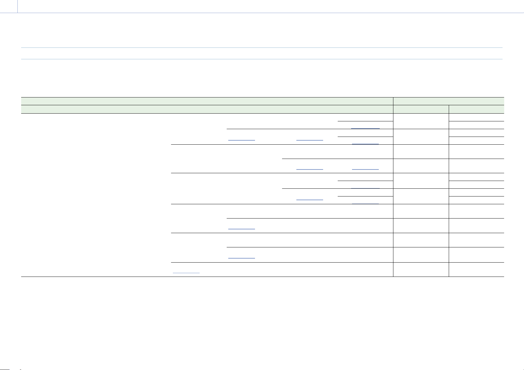
8. Appendix: Recording Formats and Output Signals
130
MONITOR OUT Connector/HDMI OUT Connector Output Formats
The digital signal from the MONITOR OUT and HDMI OUT connectors is output according to the Project category and Monitoring category settings in the menu.
For details about Project category settings combinations, see “Recording Format Settings” (page 59).
Default values are shown underlined and in
bold text.
Project Monitoring > Output Format Output format
Project Frame Rate Imager Mode Recording Format SDI 1/2 SDI 3/4 Monitor HDMI Monitor Out HDMI
59.94/50 8.2K 17:9/
6K 3:2/
6K 1.85:1/
6K 17:9/
6K 2.39:1/
5.8K 6:5/
5.8K 17:9/
4K 6:5/
4K 4:3/
4K 17:9/
4K 2.39:1
X-OCN XT
X-OCN ST
X-OCN LT
ProRes 4444 4K
ProRes 422 HQ 4K
4096×2160P 12G
1920×1080P Level A
1)
1920×1080P Level A
4096×2160P
1920×1080P
YPbPr 3G Level A
4096×2160P
1920×1080P
1920×1080P
1920×1080i 1920×1080i
4096×2160P
1920×1080P
YPbPr 3G Level A
4096×2160P
1920×1080i
1920×1080i
4096×2160P
Square Level B
2)
4096×2160P
Square Level B
2)
1920×1080P Level A 1920×1080P
1920×1080P
YPbPr 3G Level A
1920×1080P
1920×1080i 1920×1080i
1920×1080i
YPbPr 1.5G
1920×1080i
4096×2160P 2SI Level
B
2)
4096×2160P 2SI Level
B
2)
1920×1080P Level A
4096×2160P
1920×1080P
YPbPr 3G Level A
4096×2160P
1920×1080P
1920×1080P
1920×1080i
4096×2160P
1920×1080i
YPbPr 1.5G
4096×2160P
1920×1080i
1920×1080i
2048×1080P Level B
2)
1920×1080P Level B
2)
1920×1080P Level A 1920×1080P
1920×1080P
YPbPr 3G Level A
1920×1080P
1920×1080i
1920×1080i 1920×1080i
1920×1080i
YPbPr 1.5G
1920×1080i
1920×1080P Level B
2)
1920×1080P Level B
2)
1920×1080P Level A 1920×1080P
1920×1080P
YPbPr 3G Level A
1920×1080P
1920×1080i
1920×1080i 1920×1080i
1920×1080i
YPbPr 1.5G
1920×1080i
1920×1080i
1920×1080i 1920×1080i 1920×1080i
1920×1080i
YPbPr 1.5G
1920×1080i
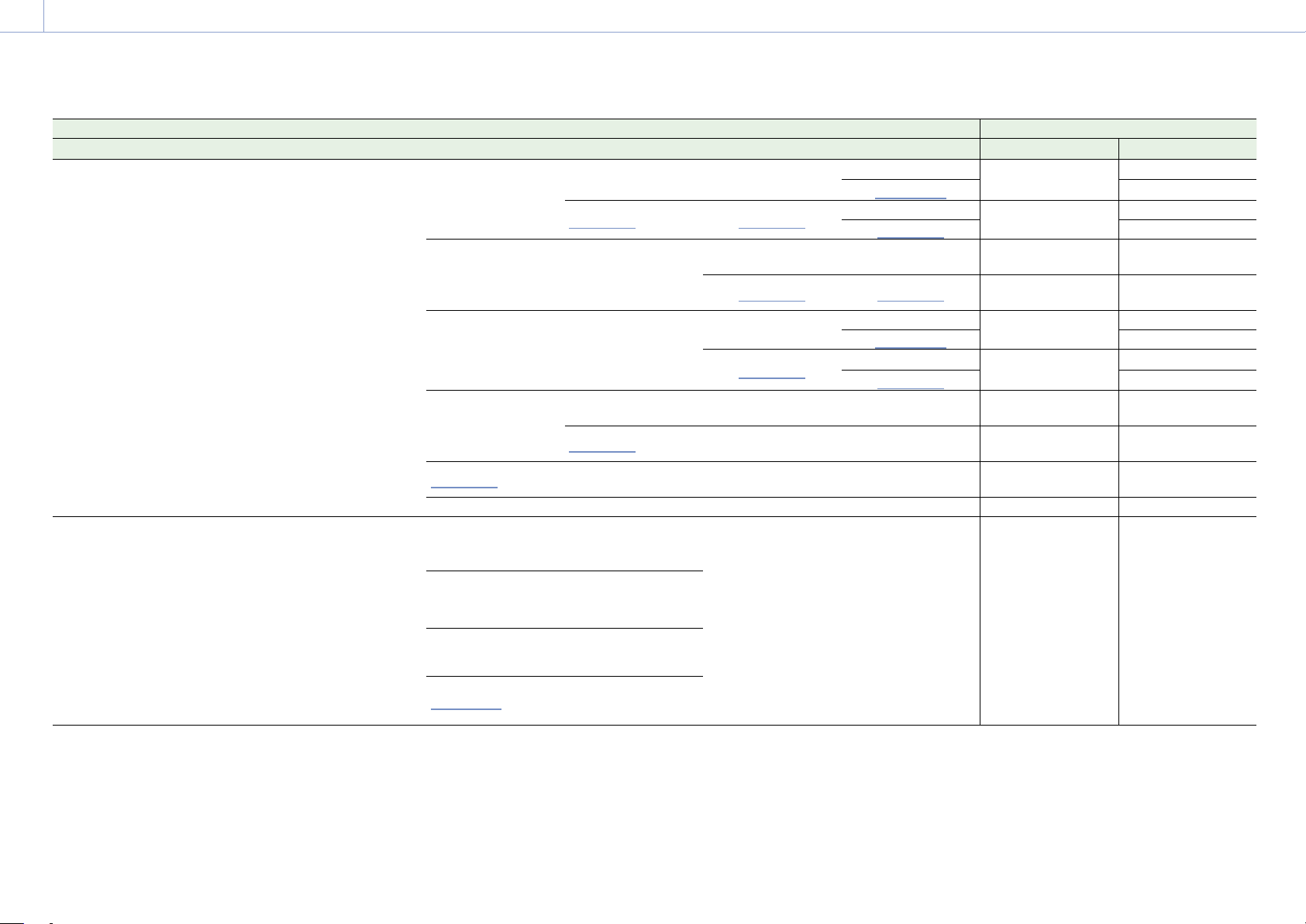
8. Appendix: Recording Formats and Output Signals
131
Project Monitoring > Output Format Output format
Project Frame Rate Imager Mode Recording Format SDI 1/2 SDI 3/4 Monitor HDMI Monitor Out HDMI
59.94/50 7.6K 16:9/
5.7K 16:9/
5.4K 16:9/
3.8K 16:9
X-OCN XT
X-OCN ST
X-OCN LT
ProRes 4444 QFHD
ProRes 422 HQ QFHD
3840×2160P 12G
1920×1080P Level A
1)
1920×1080P Level A
3840×2160P
1920×1080P
YPbPr 3G Level A
3840×2160P
1920×1080P
1920×1080P
1920×1080i 1920×1080i
3840×2160P
1920×1080P
YPbPr 3G Level A
3840×2160P
1920×1080i
1920×1080i
3840×2160P
Square Level B
2)
3840×2160P
Square Level B
2)
1920×1080P Level A 1920×1080P
1920×1080P
YPbPr 3G Level A
1920×1080P
1920×1080i 1920×1080i
1920×1080i
YPbPr 1.5G
1920×1080i
3840×2160P
2SI Level B
2)
3840×2160P
2SI Level B
2)
1920×1080P Level A
3840×2160P
1920×1080P
YPbPr 3G Level A
3840×2160P
1920×1080P
1920×1080P
1920×1080i
3840×2160P
1920×1080i
YPbPr 1.5G
3840×2160P
1920×1080i
1920×1080i
1920×1080P Level B
2)
1920×1080P Level B
2)
1920×1080P Level A 1920×1080P
1920×1080P
YPbPr 3G Level A
1920×1080P
1920×1080i
1920×1080i 1920×1080i
1920×1080i
YPbPr 1.5G
1920×1080i
1920×1080i
1920×1080i 1920×1080i 1920×1080i
1920×1080i
YPbPr 1.5G
1920×1080i
1920×1080i
3)
1920×1080i
3)
– 720×480P
3)
– 720×480P
3) 4)
47.95 8.2K 17:9/
6K 3:2/
6K 1.85:1/
6K 17:9/
6K 2.39:1/
5.8K 6:5/
5.8K 17:9/
4K 6:5/
4K 4:3/
4K 17:9/
4K 2.39:1/
3.8K 16:9
X-OCN XT
X-OCN ST
X-OCN LT
4096×2160P
Square Level B
2)
4096×2160P
Square Level B
2)
1920×1080P 1920×1080P
1920×1080P
YPbPr 1.5G
1920×1080P
4096×2160P
2SI Level B
2)
4096×2160P
2SI Level B
2)
2048×1080P Level B
2)
1920×1080P
1920×1080P
1920×1080P
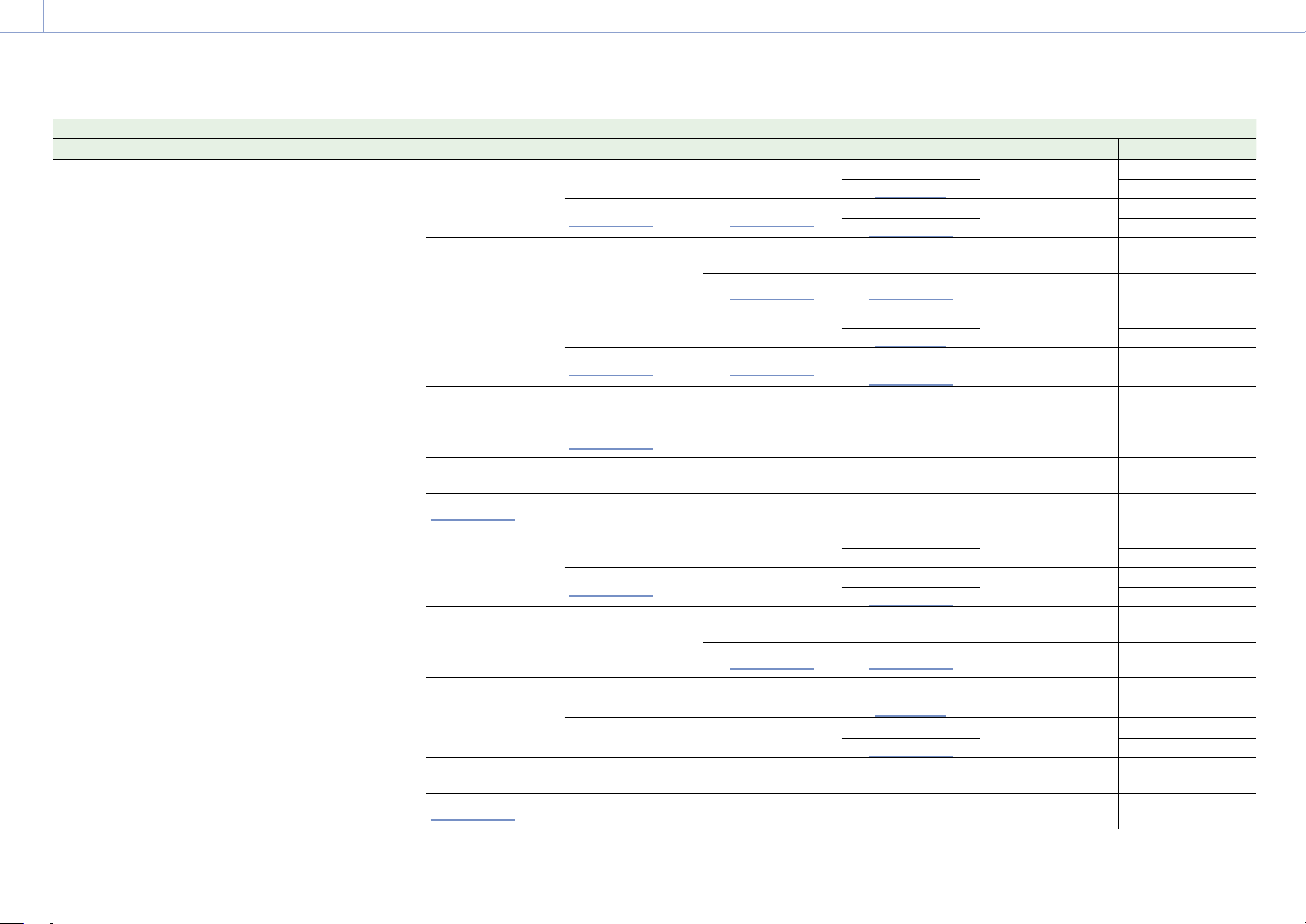
8. Appendix: Recording Formats and Output Signals
132
Project Monitoring > Output Format Output format
Project Frame Rate Imager Mode Recording Format SDI 1/2 SDI 3/4 Monitor HDMI Monitor Out HDMI
29.97/25 8.6K 3:2/
8.2K 17:9/
6K 3:2/
6K 1.85:1/
6K 17:9/
6K 2.39:1/
5.8K 6:5/
5.8K 17:9/
4K 6:5/
4K 4:3/
4K 17:9/
4K 2.39:1
X-OCN XT
X-OCN ST
X-OCN LT
ProRes 4444 4K
ProRes 422 HQ 4K
4096×2160P 6G
1920×1080P 1920×1080P
4096×2160P
1920×1080P
YPbPr 1.5G
4096×2160P
1920×1080P
1920×1080P
1920×1080PsF 1920×1080PsF
4096×2160P
1920×1080P
YPbPr 1.5G
4096×2160P
1920×1080PsF
1920×1080PsF
4096×2160P Square 4096×2160P Square
1920×1080P 1920×1080P
1920×1080P
YPbPr 1.5G
1920×1080P
1920×1080PsF 1920×1080PsF
1920×1080PsF
YPbPr 1.5G
1920×1080PsF
4096×2160P 2SI
1920×1080P 1920×1080P
4096×2160P
1920×1080P
YPbPr 1.5G
4096×2160P
1920×1080P
1920×1080P
1920×1080PsF 1920×1080PsF
4096×2160P
1920×1080P
YPbPr 1.5G
4096×2160P
1920×1080PsF
1920×1080PsF
2048×1080PsF
1920×1080P 1920×1080P 1920×1080P
1920×1080P
YPbPr 1.5G
1920×1080P
1920×1080PsF
1920×1080PsF 1920×1080PsF
1920×1080PsF
YPbPr 1.5G
1920×1080PsF
1920×1080P 1920×1080P 1920×1080P 1920×1080P
1920×1080P
YPbPr 1.5G
1920×1080P
1920×1080PsF
1920×1080PsF 1920×1080PsF 1920×1080PsF
1920×1080PsF
YPbPr 1.5G
1920×1080PsF
7.6K 16:9/
5.7K 16:9/
5.4K 16:9/
3.8K 16:9
X-OCN XT
X-OCN ST
X-OCN LT
ProRes 4444 QFHD
ProRes 422 QFHD
3840×2160P 6G
1920×1080P 1920×1080P
3840×2160P
1920×1080P
YPbPr 1.5G
3840×2160P
1920×1080P
1920×1080P
1920×1080PsF
1920×1080PsF
3840×2160P
1920×1080P
YPbPr 1.5G
3840×2160P
1920×1080PsF
1920×1080PsF
3840×2160P Square 3840×2160P Square
1920×1080P 1920×1080P
1920×1080P
YPbPr 1.5G
1920×1080P
1920×1080PsF 1920×1080PsF
1920×1080PsF
YPbPr 1.5G
1920×1080PsF
3840×2160P 2SI
1920×1080P 1920×1080P
3840×2160P
1920×1080P
YPbPr 1.5G
3840×2160P
1920×1080P
1920×1080P
1920×1080PsF 1920×1080PsF
3840×2160P
1920×1080P
YPbPr 1.5G
3840×2160P
1920×1080PsF
1920×1080PsF
1920×1080P 1920×1080P 1920×1080P 1920×1080P
1920×1080P
YPbPr 1.5G
1920×1080P
1920×1080PsF
1920×1080PsF 1920×1080PsF 1920×1080PsF
1920×1080PsF
YPbPr 1.5G
1920×1080PsF
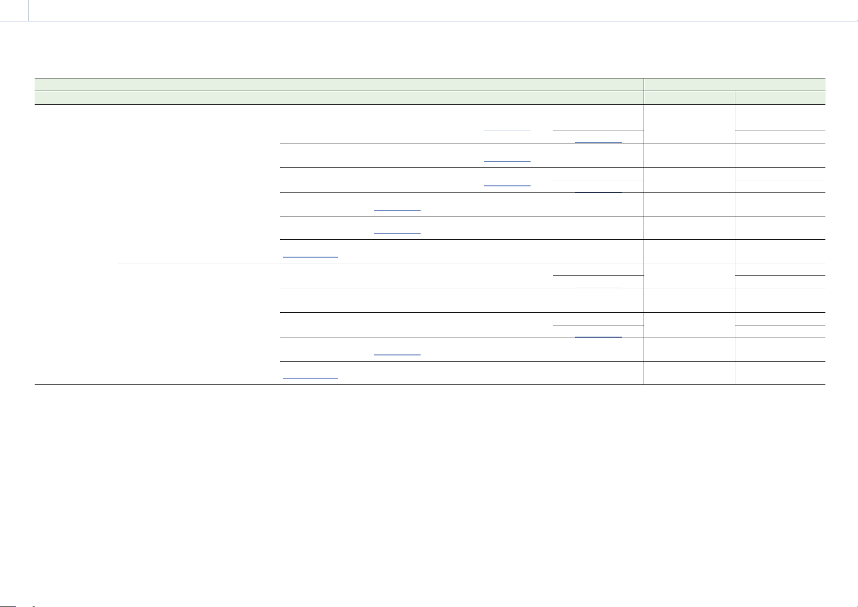
8. Appendix: Recording Formats and Output Signals
133
Project Monitoring > Output Format Output format
Project Frame Rate Imager Mode Recording Format SDI 1/2 SDI 3/4 Monitor HDMI Monitor Out HDMI
24 8.6K 3:2/
8.2K 17:9/
6K 3:2/
6K 1.85:1/
6K 17:9/
6K 2.39:1/
5.8K 6:5/
5.8K 17:9/
4K 6:5/
4K 4:3/
4K 17:9/
4K 2.39:1
X-OCN XT
X-OCN ST
X-OCN LT
ProRes 4444 4K
ProRes 422 HQ 4K
4096×2160P 6G 1920×1080P
1920×1080P
4096×2160P
1920×1080P
YPbPr 1.5G
4096×2160P
1920×1080P
1920×1080P
4096×2160P Square 4096×2160P Square
1920×1080P
1920×1080P
1920×1080P
YPbPr 1.5G
1920×1080P
4096×2160P 2SI 1920×1080P
1920×1080P
4096×2160P
1920×1080P
YPbPr 1.5G
4096×2160P
1920×1080P
1920×1080P
2048×1080PsF
1920×1080P
1920×1080P 1920×1080P
1920×1080P
YPbPr 1.5G
1920×1080P
1920×1080P
1920×1080P
1920×1080P 1920×1080P
1920×1080P
YPbPr 1.5G
1920×1080P
1920×1080PsF
1920×1080P 1920×1080P 1920×1080P
1920×1080P
YPbPr 1.5G
1920×1080P
7.6K 16:9/
5.7K 16:9/
5.4K 16:9/
3.8K 16:9
X-OCN XT
X-OCN ST
X-OCN LT
ProRes 4444 QFHD
ProRes 422 QFHD
3840×2160P 6G 1920×1080P 1920×1080P
3840×2160P
1920×1080P
YPbPr 1.5G
3840×2160P
1920×1080P
1920×1080P
3840×2160P Square 3840×2160P Square 1920×1080P 1920×1080P
1920×1080P
YPbPr 1.5G
1920×1080P
3840×2160P 2SI 1920×1080P 1920×1080P
3840×2160P
1920×1080P
YPbPr 1.5G
3840×2160P
1920×1080P
1920×1080P
1920×1080P
1920×1080P
1920×1080P 1920×1080P
1920×1080P
YPbPr 1.5G
1920×1080P
1920×1080PsF
1920×1080P 1920×1080P 1920×1080P
1920×1080P
YPbPr 1.5G
1920×1080P
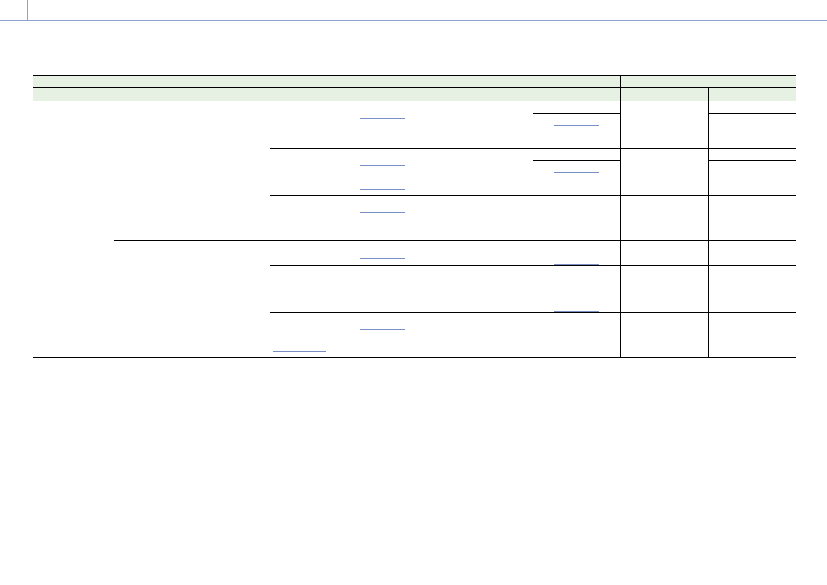
8. Appendix: Recording Formats and Output Signals
134
Project Monitoring > Output Format Output format
Project Frame Rate Imager Mode Recording Format SDI 1/2 SDI 3/4 Monitor HDMI Monitor Out HDMI
23.98 8.6K 3:2/
8.2K 17:9/
6K 3:2/
6K 1.85:1/
6K 17:9/
6K 2.39:1/
5.8K 6:5/
5.8K 17:9/
4K 6:5/
4K 4:3/
4K 17:9/
4K 2.39:1
X-OCN XT
X-OCN ST
X-OCN LT
ProRes 4444 4K
ProRes 422 HQ 4K
4096×2160P 6G
1920×1080P
1920×1080P
4096×2160P
1920×1080P
YPbPr 1.5G
4096×2160P
1920×1080P
1920×1080P
4096×2160P Square 4096×2160P Square 1920×1080P 1920×1080P
1920×1080P
YPbPr 1.5G
1920×1080P
4096×2160P 2SI
1920×1080P
1920×1080P
4096×2160P
1920×1080P
YPbPr 1.5G
4096×2160P
1920×1080P
1920×1080P
2048×1080PsF
1920×1080P
1920×1080P 1920×1080P
1920×1080P
YPbPr 1.5G
1920×1080P
1920×1080P
1920×1080P
1920×1080P 1920×1080P
1920×1080P
YPbPr 1.5G
1920×1080P
1920×1080PsF
1920×1080P 1920×1080P 1920×1080P
1920×1080P
YPbPr 1.5G
1920×1080P
7.6K 16:9/
5.7K 16:9/
5.4K 16:9/
3.8K 16:9
X-OCN XT
X-OCN ST
X-OCN LT
ProRes 4444 QFHD
ProRes 422 QFHD
3840×2160P 6G
1920×1080P
1920×1080P
3840×2160P
1920×1080P
YPbPr 1.5G
3840×2160P
1920×1080P
1920×1080P
3840×2160P Square 3840×2160P Square 1920×1080P 1920×1080P
1920×1080P
YPbPr 1.5G
1920×1080P
3840×2160P 2SI 1920×1080P 1920×1080P
3840×2160P
1920×1080P
YPbPr 1.5G
3840×2160P
1920×1080P
1920×1080P
1920×1080P
1920×1080P
1920×1080P 1920×1080P
1920×1080P
YPbPr 1.5G
1920×1080P
1920×1080PsF
1920×1080P 1920×1080P 1920×1080P
1920×1080P
YPbPr 1.5G
1920×1080P
1) The Level A signal is output even when Monitoring > Output Format > 3G SDI 1/2/3/4 Output (page 77) is set to Level B in the full menu.
2) The menu setting changes to Level A and the Level A signal is output when Monitoring > Output Format > 3G SDI 1/2/3/4 Output is set to Level A in the full menu.
3) Set when Technical > Special Configuration > SD HDMI (page 91) is set to On in the full menu.
4) Configurable when Imager Mode or Zoom to Fit is set to 16:9 and Recording Format is set to X-OCN ST. The HDMI output is 720×576P when the project frame rate is set to 50.
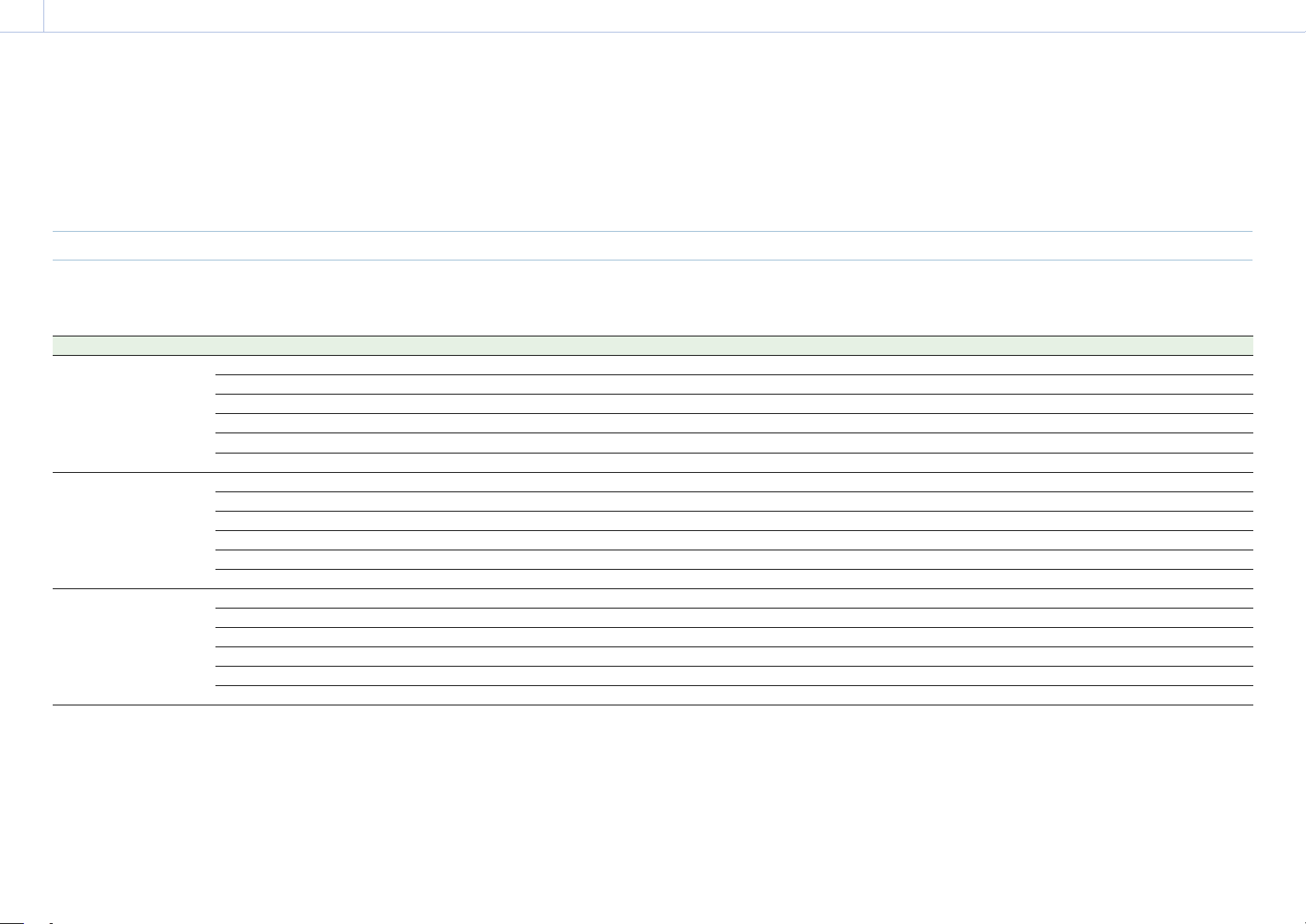
135
8. Appendix
AXS Clip Recording/Playback Time
The following tables show the recording/playback time when using AXS-A1TS66 (Unit: minutes).
[Note]
The recording and playback times are for a continuous recording as a single clip. The actual times may be shorter, depending on the number of clips recorded. The recording/playback time may vary due to usage conditions and memory
characteristics.
X-OCN Recording/Playback Time
MPC-3628
Recording Format Project Frame Rate 8.6K 3:2 8.2K 17:9 7.6K 17:9 5.8K 6:5 5.8K 17:9 5.4K 16:9
X-OCN XT 23.98/24 23 32 32 41 65 65
25 22 31 31 39 62 62
29.97 18 25 25 33 52 52
47.95 – – – 20 32 –
50 – – – – 31 31
59.94 – – – – 26 26
X-OCN ST 23.98/24 34 47 47 60 95 95
25 32 45 45 57 91 91
29.97 27 37 37 48 76 76
47.95 – 23 – 30 47 –
50 – 22 22 – 45 45
59.94 – 18 18 – 38 38
X-OCN LT 23.98/24 58 80 80 102 160 160
25 55 77 77 98 154 154
29.97 46 64 64 81 128 128
47.95 – 40 – 51 80 –
50 – 38 38 – 77 77
59.94 – 32 32
– 64 64
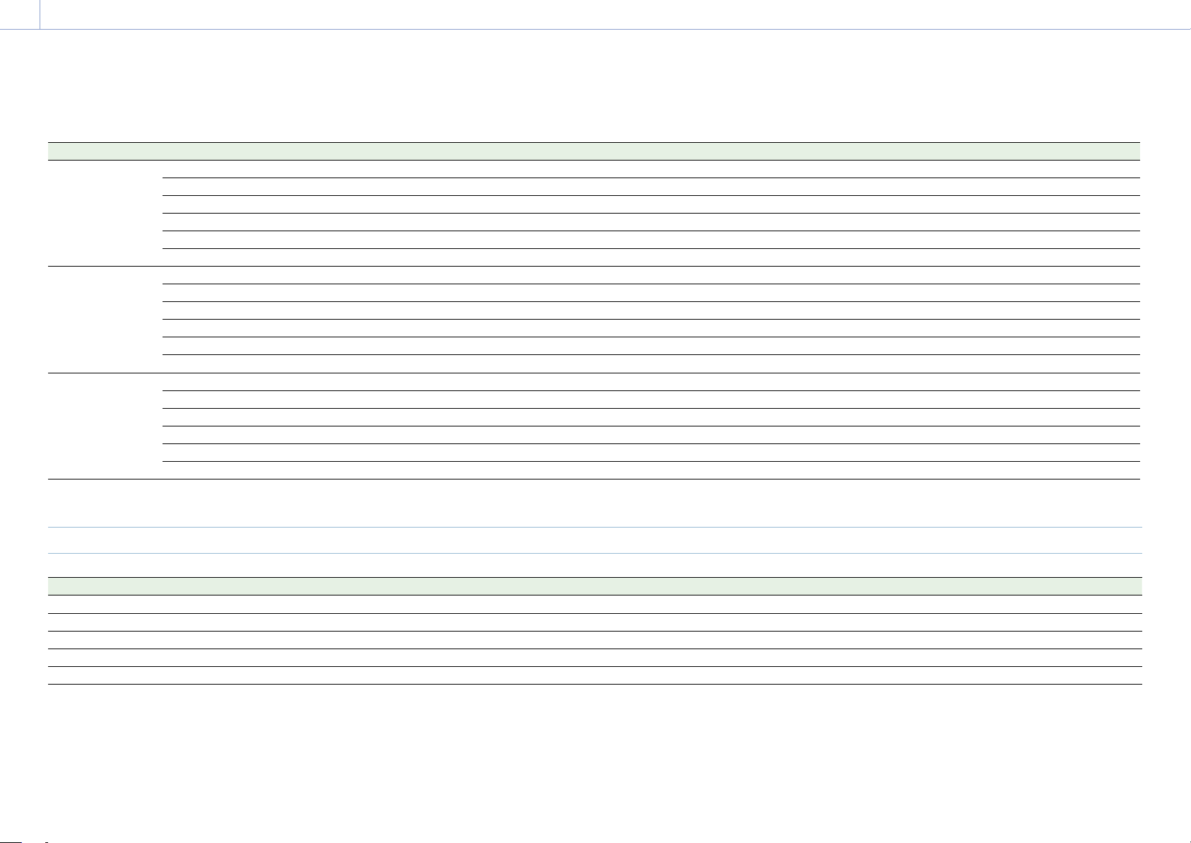
8. Appendix: AXS Clip Recording/Playback Time
136
MPC-3626
Recording Format Project Frame Rate 6K 3:2 6K 1.85:1 6K 17:9 6K 2.39:1 5.7K 16:9 4K 6:5 4K 4:3 4K 17:9 4K 2.39:1 3.8K 16:9
X-OCN XT 23.98/24 47 58 59 75 59 81 93 129 161 129
25 45 56 57 72 57 78 89 124 155 124
29.97 38 46 47 60 47 65 74 103 129 103
47.95 23 29 29 37 – 41 46 64 81 –
50 22 28 28 36 28 39 44 62 77 62
59.94 19 23 23 30 23 32 37 51 64 51
X-OCN ST 23.98/24 69 85 87 109 87 119 135 188 235 188
25 66 81 83 105 83 114 130 180 225 180
29.97 55 68 69 87 69 95 108 150 188 150
47.95 34 42 43 54 – 59 68 94 118 –
50 33 40 42 52 42 57 65 90 113
90
59.94 27 34 35 43 35 47 54 75 94 75
X-OCN LT 23.98/24 117 144 147 185 147 201 229 316 395 316
25 112 138 141 177 141 193 220 304 380 304
29.97 94 115 118 148 118 161 183 254 317 254
47.95 58 72 74 92 – 101 115 159 199 –
50 56 69 71 89 71 97 110 153 191 153
59.94 47 57 59 74 59 81 92 127 159 127
ProRes Recording/Playback Time
Project Frame Rate 4K 4444 4K 422 HQ QFHD 4444 QFHD 422 HQ
23.98/24 98 146 104 156
25 94 140 100 150
29.97 78 117 83 125
50 47 70 50 75
59.94 39 58 41 62
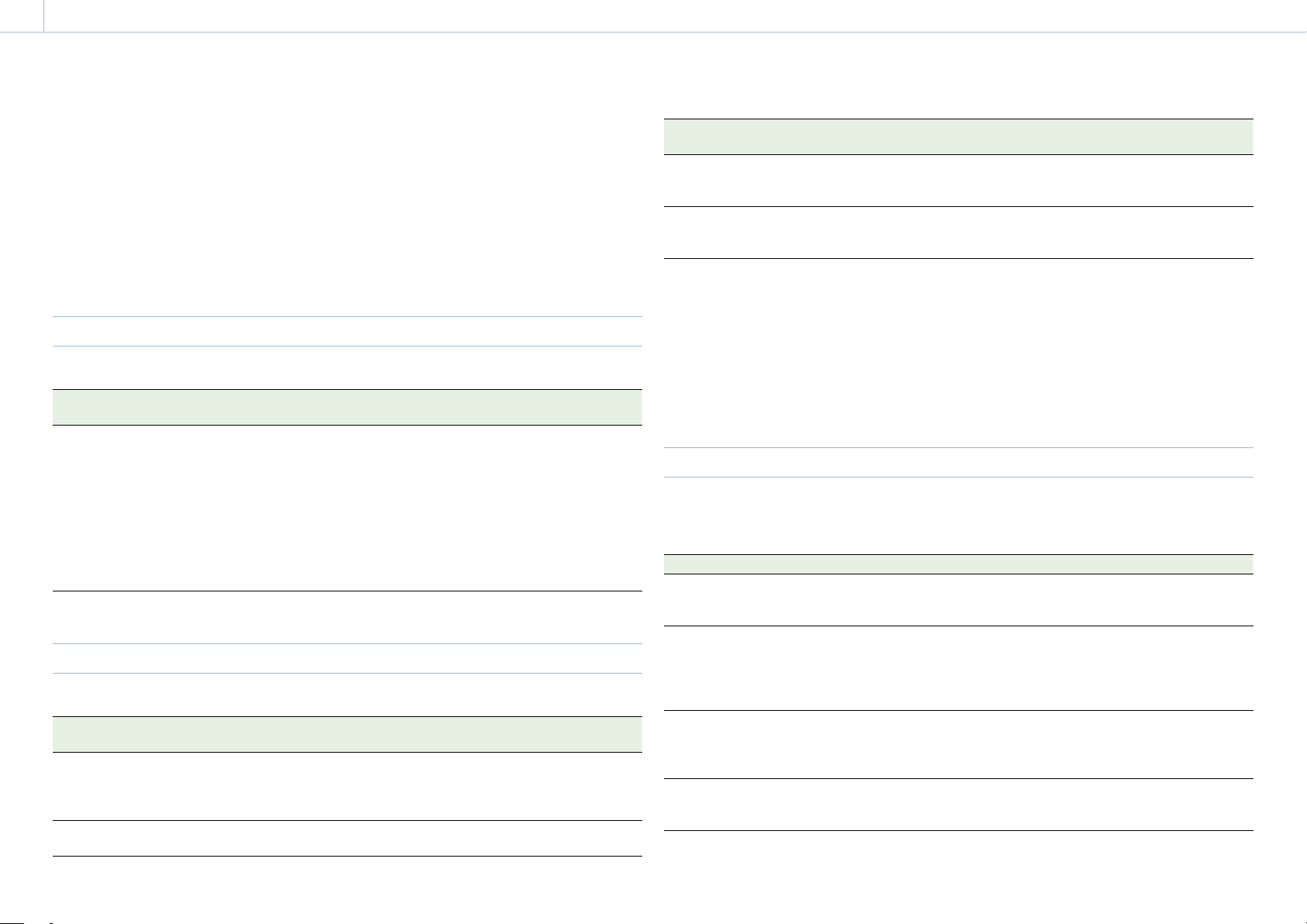
137
8. Appendix
Error/Warning Indications
If a warning, caution, or operating condition that requires confirmation occurs on the unit, a
message is displayed on the sub display, the REC lamp starts flashing, and a warning sound is
emitted.
The buzzer is output to the built-in speaker or to the headphones connected via the headphone
connector.
When the unit is turned on, a message appears on the sub display screen prompting you
to execute Auto Pixel Restoration if the auto adjustment for the image sensor (Auto Pixel
Restoration) has not been performed for a certain period of time. In this case, follow the on-
screen instructions to execute Auto Pixel Restoration (page 87).
Error Display
The unit will stop operation when the following kind of display occurs.
Error display
indication
Buzzer REC lamp Cause and Solution
E + Error code Intermittent High-speed
flashing
The unit may be defective. Recording stops even
if REC is displayed on the viewfinder/monitor
screen.
Turn off the power and check the connected
equipment, cables, and media. If the error
persists when the unit is turned on again,
contact your Sony service representative. (If
power cannot be turned off by setting the power
switch to OFF, remove the battery pack or the DC
IN source.)
Warning Display
When one of the following messages occurs, use the following table to resolve the problem.
Warning display
indication
Buzzer REC lamp Cause and Solution
Media Full
1)
Continuous High-speed
flashing
Clips could not be recorded, copied, or split
because there is no remaining capacity on the
AXS memory card.
Replace immediately.
Battery End
1)
Continuous High-speed
flashing
The battery pack is dead. Recording is disabled.
Stop operation and recharge the battery pack.
Warning display
indication
Buzzer REC lamp Cause and Solution
Temperature High
1)
Intermittent Flashing The internal temperature is high.
Turn off the unit and allow it to cool down before
operating it again.
Insufficient Voltage
1)
Continuous High-speed
flashing
The DC IN voltage is too low. Recording is
disabled.
Connect another power source.
1) Message is not displayed on the monitor screen.
About temperature warnings
The Temperature High warning may be displayed when operating within the guaranteed
operating temperature of the unit, depending on the operating mode and usage environment.
Recording does not immediately stop when these messages are displayed, but the suggestions
given in the Cause and Solution column of the table should be implemented promptly.
Caution and Operation Confirmation Display
The following caution and operation confirmation messages may appear on the monitor screen
or sub display, and warning icons may be displayed and messages displayed in the Info category
> Camera Condition in the menu. Follow the instructions provided to resolve the issue.
Display indication Cause and Solution
Backup Battery End
Please Change
The remaining capacity of the backup battery is
insufficient.
Replace the backup battery.
Cannot Use AXS(A)*
Please Change
A memory card that has been partitioned or a
memory card containing more clips that can be
handled by the unit was inserted.
The card cannot be used in the unit, and must be
replaced.
Cannot Use AXS(A)*
Unsupported File System
A card using a different file system or an
unformatted card was inserted.
The card cannot be used in the unit, and must be
replaced or formatted using the unit.
Media Error
AXS(A)* Needs to be Restored
An error occurred with the memory card. The card
requires restoration.
Restore the card.
8. Appendix: Error/Warning Indications
138
Display indication Cause and Solution
AXS(A)* Error
Recording Stopped
Playback Stopped
Recording or playback stopped because an error
occurred on the memory card.
If the problem persists, replace the memory card.
Input AES/EBU is Invalid Emphasis AES/EBU signal with unsupported emphasis was
input.
The unit only supports signals with 50 μs + 15 μs
emphasis.
Input AES/EBU is not Pro Use A signal other than Professional Use was input to
the AES/EBU input.
The unit is compatible with Professional Use only.
Fan Stopped The fan in the unit has stopped.
Avoid use under high temperature conditions.
Turn the unit off and contact a Sony service
representative.
XXXX License Y days Remaining
(XXXX: Type of license, Y: Number of days
remaining)
There are 2 days remaining before the license for
the software option will expire.
Lens I/F Error A fault was detected in the lens I/F
communication when an E-mount lens is
attached.
Check the connection to the E-mount lens.
Set the "Password" of "Authentication". Technical > Authentication > Password
(page 87) has not been configured yet.
Configure the setting.
* “AXS(A)” is displayed for the AXS memory card in slot A, and “AXS(B)” is displayed for the AXS memory card in slot B.
139
8. Appendix
Items Saved in Files
Table legend
Yes: Saved
No: Not saved
–: Not saved (temporary setting)
Shooting Menu
Item Sub-item File type
All Scene
FPS Fixed/Variable Select Yes No
FPS Select Yes No
Shutter
1)
Shutter Select Yes Yes
Step/Cont. Select Yes Yes
Add/Change Step – –
Delete Step – –
Flicker Reduce Mode Yes No
Frequency Yes No
ND ND Position Yes Yes
Exposure Index EI Select Yes Yes
Gain Gain Select Yes Yes
White Balance
1)
Color Temp. Select Yes Yes
Add/Change Step – –
Delete Step – –
Auto White Balance – –
Look Category Yes No
Preset Look Select Yes No
User 3D LUT Select Yes No
ART Select Yes No
ART Information – –
ASC CDL Process Yes No
ASC CDL Select Yes No
ASC CDL Information – –
Item Sub-item File type
All Scene
Look File Load User 3D LUT – –
Reset User 3D LUT – –
Reset All User 3D LUTs – –
Load ART – –
Reset ART – –
Reset All ARTs – –
Load ASC CDL – –
Reset ASC CDL – –
Reset All ASC CDLs – –
LUT Select SDI 1/2 Yes –
SDI 3/4 Yes No
Monitor Yes No
HDMI – –
VF LUT Yes No
ProRes Yes No
SDR Gain Yes No
1) Selection options added or edited by a user are also saved.
8. Appendix: Items Saved in Files
140
Project Menu
Item Sub-item File type
All Scene
Basic Setting Imager Mode Yes No
Project Frame Rate Yes No
Input Color Space Yes Yes
Recording Format Yes No
Base ISO Yes Yes
Anamo. De-Squeeze Yes No
Zoom to Fit Yes No
Assignable Button <1> Yes No
<2> Yes No
<3> Yes No
<4> Yes No
<VF A> Yes No
<VF B> Yes No
<VF C> Yes No
<User 1> Yes No
<User 2> Yes No
<User 3> Yes No
<User 4> Yes No
<User 5> Yes No
Special Recording Cache Rec Select Yes No
Max Cache Rec Duration Yes No
All File(Cam Setup) Load SD Card – –
Save SD Card – –
File ID Yes No
Format SD Card – –
Scene File Recall Internal Memory – –
Store Internal Memory – –
Load SD Card – –
Save SD Card – –
File ID No Yes
User Gamma Current Settings – –
Load SD Card – –
Reset – –
TC/Media Menu
Item Sub-item File type
All Scene
Timecode Mode Yes No
Manual Setting – –
Reset – –
TC Format Yes No
TC Source – –
Time Data Display Yes No
Genlock Input Source Yes No
Reference Lock Type – –
Clip Name Format Camera ID
1)
Yes No
Reel Number
1)
Yes No
Camera Position
1)
Yes No
Format Media AXS Slot A – –
AXS Slot B – –
SD Card – –
1) When you load an All file, the data saved in internal memory is not overwritten.
8. Appendix: Items Saved in Files
141
Monitoring Menu
Item Sub-item File type
All Scene
Output Format SDI 1/2 Yes No
SDI 3/4 Yes No
Monitor Yes No
HDMI Yes No
3G SDI 1/2/3/4 Output Yes No
Output Display Flip Image Yes No
Audio/Video Delay Yes No
Monitor Magnifier Mode Yes No
Monitor Magnifier Ratio Yes No
VF Display VF LUT Yes No
Overlay Yes No
Frame Line Yes No
VF Magnifier Mode Yes No
VF Magnifier Ratio Yes No
Color Yes No
SDR Gain Yes No
VF Function Double Speed Scan Yes No
Peaking Frequency Yes No
Assign<VF A> Yes No
Assign<VF B> Yes No
Assign<VF C> Yes No
Zebra Yes No
Zebra Select Yes No
Zebra1 Level Yes No
Zebra1 Aperture Level Yes No
Zebra2 Level Yes No
Overlays/Frame Line VF Yes No
SDI 1/2 Yes No
SDI 3/4 Yes No
Monitor Yes No
HDMI – –
Overlay A/B Setup Yes No
Frame Line A/B Setup Yes No
Item Sub-item File type
All Scene
Frame Line Setup Color Yes No
Center Marker Yes No
Aspect Ratio Yes No
Aspect Ratio Type Yes No
Surround View Type Yes No
Mask Level Yes No
Safety Zone Yes No
Aspect Safety Zone Yes No
Frame Line on Playback Yes No
User Frame Line 1 Select Yes No
Preset Aspect Ratio Yes No
Scaling Yes No
Preset Aspect Ratio Type Yes No
Aspect Ratio(Pixels) – –
Width Yes No
Height Yes No
H Position Yes No
V Position Yes No
Variable Aspect Type – –
User Frame Line 2 Select Yes No
Preset Aspect Ratio Yes No
Scaling Yes No
Preset Aspect Ratio Type – –
Aspect Ratio(Pixels) – –
Width Yes No
Height Yes No
H Position Yes No
V Position Yes No
Variable Aspect Type – –

8. Appendix: Items Saved in Files
142
Audio Menu
Item Sub-item File type
All Scene
Audio Input Internal Mic Select Yes No
XLR Audio L Select Yes No
XLR Audio R Select Yes No
XLR Audio L Level Yes No
XLR Audio R Level Yes No
XLR Mic Reference Yes No
Audio Monitor Monitor CH Yes No
Monitor Level Yes No
Audio Configuration Alarm Level Yes No
Input Limiter Mode Yes No
AGC Level Yes No
AGC Mono/Stereo Yes No
MIC Input Mono/Stereo Yes No
Phantom Power +48V Yes No
Monitor Output CH Pair Yes No
Headphone Mono/ST Yes No
Paint Menu
Item Sub-item File type
All Scene
Black Master Black Yes Yes
R Black Yes Yes
B Black Yes Yes
Flare Setting Yes Yes
Master Flare Yes Yes
R Flare Yes Yes
G Flare Yes Yes
B Flare Yes Yes
Gamma Setting Yes Yes
Gamma Category – –
Gamma Select Yes Yes
Black Gamma Setting Yes Yes
Range Yes Yes
Master Black Gamma Yes Yes
Knee Setting Yes Yes
Point Yes Yes
Slope Yes Yes
White Clip Setting Yes Yes
Level Yes Yes
Detail Setting Yes Yes
Level Yes Yes
H/V Ratio Yes Yes
Crispening Yes Yes
Level Depend Yes Yes
Level Depend Level Yes Yes
Frequency Yes Yes
Knee Aperture Yes Yes
Knee Aperture Level Yes Yes
Limit Yes Yes
White Limit Yes Yes
Black Limit Yes Yes
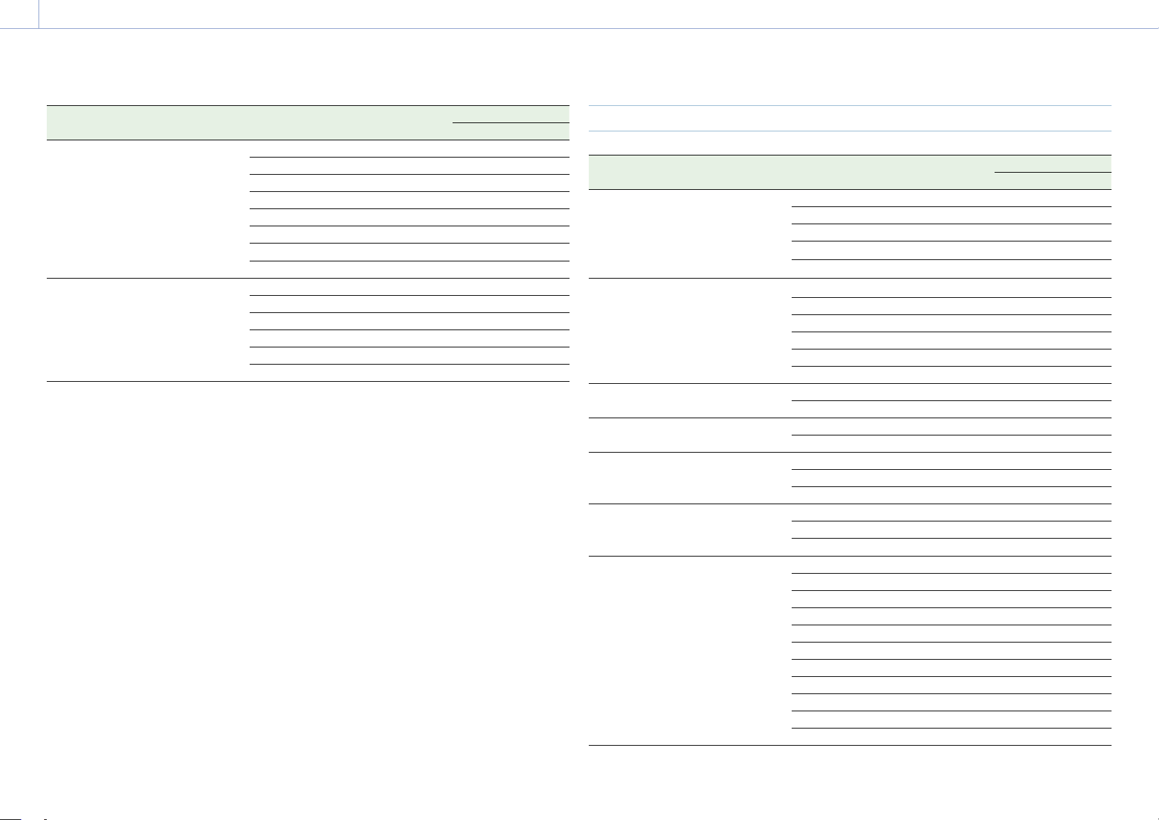
8. Appendix: Items Saved in Files
143
Item Sub-item File type
All Scene
Matrix Setting Yes Yes
User Matrix Yes Yes
User Matrix R-G Yes Yes
User Matrix R-B Yes Yes
User Matrix G-R Yes Yes
User Matrix G-B Yes Yes
User Matrix B-R Yes Yes
User Matrix B-G Yes Yes
Multi Matrix Setting Yes Yes
Area Indication No No
Reset – –
Axis No No
Hue Yes Yes
Saturation Yes Yes
Technical Menu
Item Sub-item File type
All Scene
System Configuration Fan Control Yes No
Shutter Mode Yes Yes
SDI Rec Remote Trigger Yes No
Level Gauge Adjust – –
Level Gauge Reset – –
Lens Configuration PL-Mt Interface Position Yes No
PL-Mt Voltage Yes No
Focus Distance Format Yes No
Lens 12pin Yes No
E-Mount Shading Comp. Yes No
E-Mt Chro. Aber. Comp. Yes No
Auto Pixel Restore Auto Pixel Restoration – –
Reset – –
Authentication User Name No No
Password No No
Network Setting Yes No
LAN Yes No
Wireless Yes
1)
No
Alerts & Tally Rec Light Yes No
Rec Start/Stop Beep Yes No
Media Near Full Alarm Yes No
Batt./Voltage Alarm Near End:Info Battery Yes No
End:Info Battery Yes No
Near End:Sony Battery Yes No
End:Sony Battery Yes No
Near End:Other Battery Yes No
End:Other Battery Yes No
Detected Battery – –
DC Low Voltage1 Yes No
DC Low Voltage2 Yes No
DC(24V) Low Voltage1 Yes No
DC(24V) Low Voltage2 Yes No
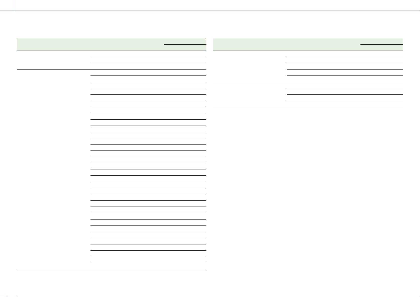
8. Appendix: Items Saved in Files
144
Item Sub-item File type
All Scene
Panel Control Brightness level Yes No
Lock Operator Side Yes No
Lock Assistant Side Yes No
False Color Level Yes No
Red Yes No
Red Upper Limit Yes No
Red Lower Limit Yes No
Yellow Yes No
Yellow Upper Limit Yes No
Yellow Lower Limit Yes No
Orange Yes No
Orange Upper Limit Yes No
Orange Lower Limit Yes No
Pink Yes No
Pink Upper Limit Yes No
Pink Lower Limit Yes No
Light Pink Yes No
Light Pink Upper Limit Yes No
Light Pink Lower Limit Yes No
Cyan Yes No
Cyan Upper Limit Yes No
Cyan Lower Limit Yes No
Green Yes No
Green Upper Limit Yes No
Green Lower Limit Yes No
Light Blue Yes No
Light Blue Upper Limit Yes No
Light Blue Lower Limit Yes No
Blue Yes No
Blue Upper Limit Yes No
Blue Lower Limit Yes No
Purple Yes No
Purple Upper Limit Yes No
Purple Lower Limit Yes No
Reset – –
Item Sub-item File type
All Scene
Test Signals Color Bars Yes No
Color Bar Type Yes No
1kHz Tone on Color Bars Yes No
Test Saw Yes No
Test Saw Type Yes No
Special Configuration RM/RCP Paint Control Yes No
NR(4K 17:9/16:9) Yes Yes
SD HDMI Yes No
360˚ Shutter Setting Yes No
1) The following items are not saved.
• Scan Networks
• SSID
• Password
• WPS
• MAC Address
• Regenerate Password
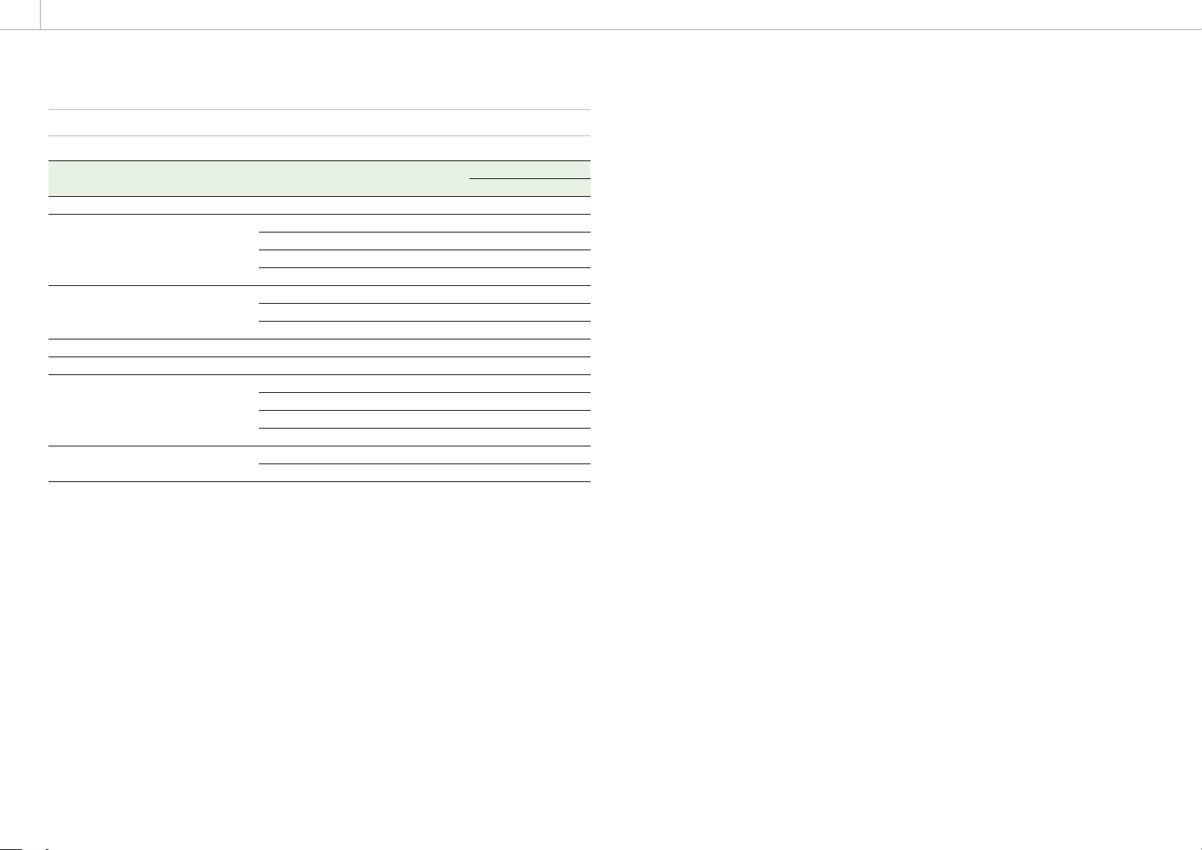
8. Appendix: Items Saved in Files
145
Maintenance Menu
Item Sub-item File type
All Scene
Language Select Yes No
Clock Set Time Zone Yes No
Date Mode Yes No
Date – –
Time – –
Hours Meter Hours (System) – –
Hours (Resettable) – –
Reset – –
Reset to Default Reset – –
Network Reset Reset – –
License Options Install: xxx – –
Anamorphic – –
Full-Frame – –
Unique Device ID – –
Firmware Version – –
Firmware Update – –
[Note]
When Technical > Special Configuration > RM/RCP Paint Control (page 91) is set to On in the full menu, the
following remote control unit items (page 116) are also saved in an All file.
• Black
• Flare
• Gamma
1)
• Black Gamma
1)
• Gain
1) Except when set to S-Log3.
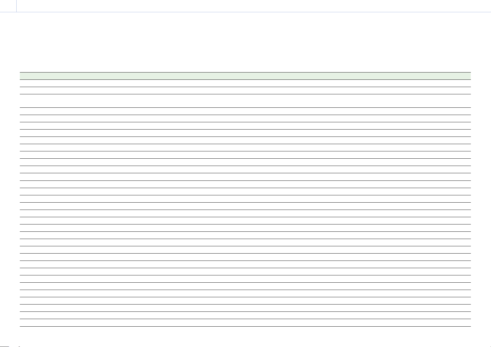
146
8. Appendix
Recording and Output Metadata List
Table legend
Opt: Included if information is available (optional)
Yes: Defined
–: Not defined
Item Notation example in RAW Viewer RAW/X-OCN MXF RAW/X-OCN XML ProRes MXF ProRes XML HD-SDI
Creation Date 2021-10-29 11:04:05 Yes Yes Yes Yes –
Last Update 2021-10-30 11:04:05 – Yes Yes Yes –
UMID 060A2B340101010501010D4313000000070BF4
1D2F494EB7A16DD045A68CDF2E
Yes Yes Yes Yes –
Start 03:36:29:20 Yes Yes Yes Yes –
End 03:36:32:19 Yes Yes Yes Yes –
Duration 00:00:03:00 Yes Yes Yes Yes –
Poster Frame – – – – –
Recording Mode – Yes – Yes –
Drop Frame NDF Yes Yes Yes Yes –
Camera VENICE/CineAltaV Yes Yes Yes Yes –
Video Codec X-OCN XT Yes Yes Yes Yes –
Resolution 6048×4032 Yes Yes Yes Yes –
Aspect Ratio 3:2 Yes Yes Yes Yes –
Format FPS 23.98p Yes Yes Yes Yes –
Capture FPS 23.98p Yes Yes Yes Yes –
Pixel Aspect 1:1 – Yes – – –
Flip normal – Yes – – –
Number of Audio Channels 4 Yes Yes Yes Yes –
Audio Codec
LPCM Yes Yes Yes Yes –
Audio Bit Depth 24 Yes Yes Yes Yes –
Audio Sampling Rate 48000 Yes Yes Yes Yes –
Auto Exposure Mode ManualExposureMode Yes – Yes – Yes
Exposure Index 500 Yes Yes Yes Yes Yes
Auto Focus Sensing Area Setting ManualFocusMode Opt – Opt – Opt
ND Filter Wheel 1/4 Yes Yes Yes Yes Yes
Image Sensor Dimension Effective Width 35925um Yes – Yes – Yes
Image Sensor Dimension Effective Height 23950um Yes – Yes – Yes
Image Sensor Readout Mode ProgressiveFrame Yes Yes Yes Yes Yes
Shutter Speed Angle 172.50deg Yes Yes Yes Yes Yes
Shutter Speed Time 1/50sec Yes – Yes – Yes
Camera Master Gain Adjustment 0.00dB Yes – Yes – Yes
ISO Sensitivity 500 Yes Yes Yes Yes Yes
Electrical Extender Magnification 100% Yes – Yes – Yes

8. Appendix: Recording and Output Metadata List
147
Item Notation example in RAW Viewer RAW/X-OCN MXF RAW/X-OCN XML ProRes MXF ProRes XML HD-SDI
Auto White Balance Mode PresetWhiteBalanceSetup Yes – Yes – Yes
White Balance 5500 Yes Yes Yes Yes Yes
Tint Correction 0.00000 Yes – Yes Yes Yes
Camera Master Black Level 3.0% – – Yes – Yes
Capture Gamma Equation scene-linear Yes Yes Yes Yes Yes
Gamma for CDL rec709 Yes Yes Yes Yes Yes
Color Primaries (Capture Color Primaries) – – Yes Yes Yes
Camera Attributes MPC-36289999999Version5.00 Yes Yes Yes Yes Yes
Effective Marker Aspect Ratio 6048:3202 Yes Yes Yes Yes Yes
User Frame Line 1 1920×1080+0+0 Yes – Yes – Yes
User Frame Line 2 1920×1080+0+0 Yes – Yes – Yes
Active Area Aspect Ratio 6048:4032 Yes Yes Yes Yes Yes
Pixel Aspect Ratio 1:1 Yes Yes Yes Yes Yes
Image Orientation normal Yes – Yes Yes Yes
Raw Black Code 512 Yes Yes – – –
Raw Gray Code 1504 Yes Yes – – –
Raw White Code 5472 Yes Yes – – –
Gamma for Look s-log3-cine Yes Yes Yes Yes Yes
Color for Look s-gamut3-cine
Yes Yes Yes Yes Yes
Pre-CDL Transform LUT:SL3SG3Ctos709.cube Yes Yes Yes Yes Yes
Post-CDL Transform none Yes Yes Yes Yes Yes
Look Process Baked false Yes Yes Yes Yes Yes
Monitoring Characteristics rec709 Yes Yes Yes Yes Yes
Monitoring Base Curve rec709 Yes Yes Yes Yes Yes
Monitoring Color Primaries rec709 Yes Yes Yes Yes Yes
Monitoring Coding Equations rec709 Yes Yes Yes Yes Yes
Monitoring Descriptions LUT:SL3SG3Ctos709.cube Yes Yes Yes Yes Yes
Camera Tilt Angle 2.70000 Yes – Yes – Yes
Camera Roll Angle 1.30000 Yes – Yes – Yes
Focus Distance 2296mm Opt – Opt – Opt
Aperture Value 3.14 Opt – Opt – Opt
Aperture Ring T Stop Position 2.8 + 3/10 Opt – Opt – Opt
Current Focal Length 0mm Opt – Opt – Opt
Hyperfocal Distance 219224mm Opt – Opt – Opt
Near Focus Distance 2273mm Opt – Opt – Opt
Far Focus Distance 2319mm Opt – Opt – Opt
Horizontal Field of View 27.9deg Opt – Opt – Opt

8. Appendix: Recording and Output Metadata List
148
Item Notation example in RAW Viewer RAW/X-OCN MXF RAW/X-OCN XML ProRes MXF ProRes XML HD-SDI
Entrance Pupil Position +51mm Opt – Opt – Opt
Normalised Zoom Value 0.000 Opt – Opt – Opt
Lens Serial Number xxxxxxxx Opt – Opt – Opt
Iris F-Number 2.87 Opt – Opt – Opt
Iris T-Number 3.1 Opt – Opt – Opt
Iris Ring Position Opt – Opt – Opt
Focus Position from Image Plane 2.296m Opt – Opt – Opt
Focus Ring Position Opt – Opt – Opt
Macro Setting OFF Opt – Opt – Opt
Lens Zoom 35mm Still Camera Equivalent 85mm Opt – Opt – Opt
Lens Zoom Actual Focal Length 85mm Opt – Opt – Opt
Zoom Ring Position Opt – Opt – Opt
Anamorphic Lens Squeeze Ratio Opt – Opt – Opt
Optical Extender Magnification 100% Opt – Opt – Opt
Lens Attributes xxxxxxxx Opt Opt Opt Opt Opt
Cooke /i technology Opt – Opt – Opt
Cooke /i2 technology Opt – Opt – Opt
Cooke /i3 technology Opt – Opt – Opt
Zeiss eXtended metadata Opt – Opt – Opt
Description –
– – – –
Circle – – – – –
Project – – – – –
Director Name – – – – –
Director of Photography Name – – – – –
Production – – – – –
Camera Index – Yes – Yes –
Reel – Yes – Yes –
Scene – – – – –
Cut – – – – –
Take – – – – –
Shot – Yes – Yes –
Mark In – – – – –
Mark Out – – – – –

149
8. Appendix
Licenses
On Accessing Software to which
the GPL/LGPL Applies
This product uses software to which the
GPL/LGPL applies. This informs you that you
have a right to have access to, modify, and
redistribute source code for these software
programs under the conditions of the GPL/
LGPL.
The source code is provided on the internet.
Use the following URL and follow the
download instructions.
http://www.sony.net/Products/Linux/
common/search.html
We would prefer that you do not contact us
about the contents of the source code.
For the content of these licenses, connect
the unit to a network and view the OSS
Information screen (page 103) on the web
remote control screen.
Open Source Software Licenses
On the basis of license contracts between
Sony and the software copyright holders, this
product uses open software.
To meet the requirements of the software
copyright holders, Sony is obligated to inform
you of the content of these licenses.
For the content of these licenses, connect
the unit to a network and view the OSS
Information screen (page 103) on the web
remote control screen.

150
8. Appendix
Specifications
General Specifications
Mass MPC-3628: Approx. 4.3 kg (9 lb 7.7 oz)
MPC-3626: Approx. 4.2 kg (9 lb 4.2 oz)
(excluding handle, VF attachment)
Dimensions
See page 152.
Power requirements
12V DC (11V to 17V)
24V DC (22V to 32V)
Power consumption
MPC-3628:
Unit nominal power consumption:
Approx. 76W (8.6K 3:2, 24 FPS,
X-OCN XT recording, excluding
viewfinder and peripheral
devices)
Unit maximum power
consumption: Approx. 100W (8.2K
17:9, 60 FPS, X-OCN ST recording,
40°C (104°F) environment, 32V
DC input, excluding viewfinder
and peripheral devices)
Total maximum power
consumption: Approx. 220W
(22V to 32V DC input, including
viewfinder and peripheral
devices)
MPC-3626:
Unit nominal power consumption:
Approx. 73W (6K 3:2, 24 FPS,
X-OCN XT recording, excluding
viewfinder and peripheral
devices)
Unit maximum power
consumption: Approx. 94W (6K
3:2, 60 FPS, X-OCN ST recording,
40°C (104°F) environment, 32V
DC input, excluding viewfinder
and peripheral devices)
Total maximum power
consumption: Approx. 220W
(22V to 32V DC input, including
viewfinder and peripheral
devices)
Operating temperature
0°C to 40°C (32 °F to 104 °F)
Storage temperature
–20°C to +60°C (–4 °F to +140 °F)
Continuous operating time
Approx. 35 minutes (when using
BP-GL95B)
Recording format (video)
X-OCN XT
X-OCN ST
X-OCN LT
ProRes 4444 4K
ProRes 4444 QFHD
ProRes 422 HQ 4K
ProRes 422 HQ QFHD
Recording format (audio)
LPCM 8CH (2CH recording/playback), 24-bit,
48kHz
Recording project frame rate
X-OCN XT/ST/LT (MPC-3628):
8.6K 3:2
29.97P/25P/24P/23.98P
8.2K 17:9/5.8K 17:9
59.94P/50P/47.95P/29.97P/25P/
24P/23.98P
7.6K 16:9/5.4K 16:9
59.94P/50P/29.97P/25P/24P/
23.98P
5.8K 6:5
47.95P/29.97P/25P/24P/23.98P
X-OCN XT/ST/LT (MPC-3626):
6K 3:2/6K 1.85:1/6K 17:9/6K 2.39:1/4K
6:5/4K 4:3/4K 17:9/4K 2.39:1
59.94P/50P/47.95P/29.97P/25P/
24P/23.98P
5.7K 16:9/3.8K 16:9
59.94P/50P/29.97P/25P/24P/
23.98P
4K 4:3 Surround/4K 17:9
Surround/3.8K 16:9 Surround
29.97P/25P/24P/23.98P
ProRes 4444
4K: 4096×2160
59.94P/50P/29.97P/25P/24P/
23.98P
QFHD: 3840×2160
59.94P/50P/29.97P/25P/24P/
23.98P
ProRes 422 HQ
4K: 4096×2160
59.94P/50P/29.97P/25P/24P/
23.98P
QFHD: 3840×2160
59.94P/50P/29.97P/25P/24P/
23.98P
Recording/playback time
See page 135.
Camera
Imaging device
35 mm full size, single-chip CMOS
image sensor
Number of pixels
MPC-3628: 50.0 M (total)
MPC-3626: 24.8 M (total)
Built-in filters
ND filter A
Clear 0.3
(1/2)
0.6
(1/4)
ND filter B Clear Clear 0.3
(1/2)
0.6
(1/4)
0.9
(1/8)
0.9
(1/8)
1.2
(1/16)
1.5
(1/32)
1.8
(1/64)
1.8
(1/64)
2.1
(1/128)
2.4
(1/256)
ISO sensitivity
MPC-3628:
ISO 800
ISO 3200
MPC-3626:
ISO 500
ISO 2500
Lens mount
PL-mount (with lens mount adaptor)
E-mount (without lens mount
adaptor)
Flange focal length
PL-mount: 52mm
E-mount: 18mm
Latitude MPC-3628: 16 stops
MPC-3626: 15+ stops
Input/Output
Audio input
CH-1/CH-2: XLR-type 5-pin (female)
(1), LINE / AES/EBU / MIC /
MIC+48V selectable
DC input XLR-type 4-pin (male) (1), 11V to 17V
or 22V to 32V DC

8. Appendix: Specifications
151
DC output (12V)
LEMO 2-pin (1),
11V to 17V DC (Output voltage:
Same as input voltage, Maximum
output current: 1.0 A),
22V to 32V DC (Output voltage:
16.8V, Maximum output current:
1.0A), Using battery adaptor
[Note]
Connect to the 12V OUT connector only devices with
current consumption of 1.0A or lower.
DC output (24V)
Fischer 3-pin (2),
11V to 17V DC (Output voltage:
24V, Maximum output current:
1.0A),
22V to 32V DC (Output voltage:
Same as input voltage, Maximum
output current: 2.0A)
[Note]
Connect to the 24V OUT connector only devices with
current consumption of 1.0A or lower when the input
voltage is 11V to 17V, or 2.0A or lower when the input
voltage is 22V to 32V.
SDI output BNC type (4)
3G-SDI: SMPTE ST424/425
Level B-DL/DS
HD SDI: SMPTE ST292 compliant
AUX BNC type (1)
Viewfinder output
LEMO 26-pin (1)
Network RJ45 type (1)
Remote control
8-pin (1)
MONITOR output
BNC type (1)
HD SDI: SMPTE ST292 compliant
Timecode input
TC IN: BNC type (1)
GENLOCK input
BNC type (1)
HDMI output
Type A (1)
External device connector
USB host: Type A (1)
Headphones output
Stereo mini jack (1)
Speaker output
Monaural
Media Slots
Type AXS-A card (2)
SD card (1)
Supplied Accessories
VF attachment (1)
Handle (1)
VF cable (1) (A-2203-745-A)
Shim (circular) (1) (4-730-328-11)
Shim (1/3 arc) (15) (4-730-328-21)
E-mount lens cap (1)
PL-mount lens cap (1)
Cover for 6K imager block (1) (A-5040-737-A)
(MPC-3628 only)
Before Using This Unit (1)
Related Accessories
0.7-inch type viewfinder
DVF-EL200, DVF-L700
Camera Extension System
CBK-3610XS
Wireless LAN Adaptor
CBK-WA02
Remote Control Unit
RM-B170/B750
RCP-1000/1500/1530/3500
RCP-1001/1501/3100/3501
Card Reader
AXS-AR3
Shoulder Adaptor (attaches to VCT-14 using V
shoe)
VCT-FSA5
E-mount lens
SELP28135G, SEL1224GM, SEL1635GM,
SEL2470GM, SEL70200GM,
SEL100400GM, SEL24F14GM,
SEL35F14GM, SEL50F12GM,
SEL85F14GM, SEL100F28GM
Battery Pack
BP-GL95B
Microphone
ECM-680S, ECM-678*, ECM-674*
* EC-0.5X3F5M 3-pin XLR to 5-pin XLR
adaptor cable required
Dual Battery Adaptor
BKW-L200 (connection via battery
connection adaptor)
SDI/HDMI Monitor
BVM series, PVM series, LMD series
Design and specifications are subject to
change without notice.
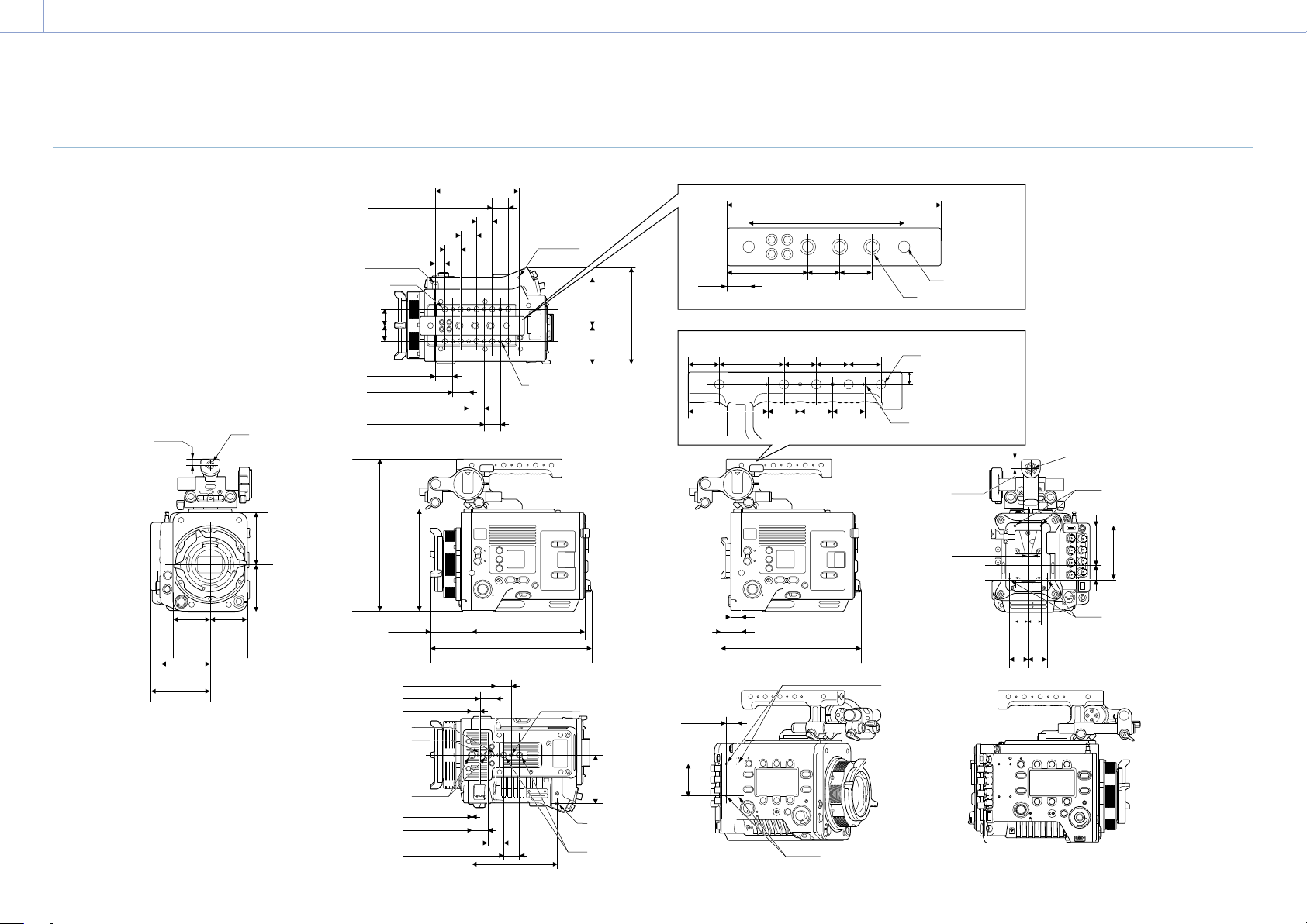
8. Appendix: Specifications
152
Dimensions
27.7 (1
1
/
8
)
13 (
17
/
32
)
Ø5.2, Depth: 5
UNC 1/4-20, Depth: 9
2-UNC 3/8-16,
Depth: 9
M3, Depth: 5.5
2-UNC 3/8-16,
Depth: 9
UNC 1/4-20, Depth: 9
0.5 (
1
/
32
)
25 (1)
25 (1)
25 (1)
25 (1)
15.2 (
5
/
8
)
25 (1)
25 (1)
25 (1)
25 (1)
25 (1)
25 (1)
25 (1)
25 (1)
25 (1)
25 (1)
77 (3
1
/
8
)
77
(3
1
/
8
)
16.5
(
21
/
32
)
61.5
(2
1
/
2
)
61.5
(2
1
/
2
)
4.45
(
11
/
64
)
14
(
9
/
16
)
84
(3
3
/
8
)
22.6 (
29
/
32
)
61.4 (2
1
/
2
)
25
(1)
25
(1)
25
(1)
25
(1)
25
(1)
8.75
(
11
/
32
)
50
(2)
24
(
31
/
32
)
25
(1)
25
(1)
25
(1)
61.1
(2
1
/
2
)
20
(
13
/
16
)
20
(
13
/
16
)
30
(1
3
/
16
)
30.6 (1
1
/
4
)
18 (
23
/
32
)
30
(1
3
/
16
)
M2.6, Depth: 8.5
(Counterbore Ø2.75, Depth: 3.3)
10-UNC 3/8-16,
Depth: 10
10-UNC 1/4-20,
Depth: 10
M3, Depth: 5.5
64.6 (2
5
/
8
)
176.3 (7)
250 (9
7
/
8
)
216 (8
5
/
8
)
19 (
3
/
4
)
2-M3, Depth: 5
4-M3, Depth:
5.5
4-M3, Depth:
5.5
2-M3, Depth: 5
Unit: mm
(inches)
135 (5
3
/
8
)
UNC 1/4-20,
Depth: 9
UNC 3/8-16,
Depth: 7
9.25
(
3
/
8
)
2-UNC 1/4-20
3-UNC 3/8-16
10-UNC 1/4-20,
Depth: 11
8-M3, Depth: 5
152
(6)
120 (4
3
/
4
)
165 (6
1
/
2
)
134 (5
3
/
8
)
57.1
(2
1
/
4
)
57.1
(2
1
/
4
)
76 (3)
91.1
(3
5
/
8
)
80
(3
1
/
4
)
50.2
(2)
73
(2
7
/
8
)
236.5
(9
3
/
8
)
158
(6
1
/
4
)

8. Appendix: Specifications
153
Trademarks
• The terms HDMI and HDMI High-Definition
Multimedia Interface, and the HDMI Logo
are trademarks or registered trademarks of
HDMI Licensing Administrator, Inc. in the
United States and other countries.
• All system names and product names are
registered trademarks or trademarks of
their respective owners. Trademarked items
are not indicated by ® or ™ symbols in this
document.