
Network Speed Dome PTZ Camera Web
5.0
User's Manual
ZHEJIANG DAHUA VISION TECHNOLOGY CO., LTD. V1.0.2

I
Foreword
General
This manual introduces the functions and operations of the Network Speed Dome PTZ Camera
(hereinafter referred to as "the Camera"). Read carefully before using the device, and keep the
manual safe for future reference.
Safety Instructions
The following signal words might appear in the manual.
Signal Words Meaning
Indicates a high potential hazard which, if not avoided, will result in
death or serious injury.
Indicates a medium or low potential hazard which, if not avoided,
could result in slight or moderate injury.
Indicates a potential risk which, if not avoided, could result in
property damage, data loss, reductions in performance, or
unpredictable results.
Provides methods to help you solve a problem or save time.
Provides additional information as a supplement to the text.
Revision History
Revision Version Revision Content Release Time
V1.0.2 Modified the address information. April 2023
V1.0.1 Added cellular network function. August 2022
V1.0.0 First release. September 2021
Privacy Protection Notice
As the device user or data controller, you might collect the personal data of others such as their face,
fingerprints, and car plate number. You need to be in compliance with your local privacy protection
laws and regulations to protect the legitimate rights and interests of other people by implementing
measures which include but are not limited: Providing clear and visible identification to inform
people of the existence of the surveillance area and provide required contact information.
Interface Declaration
This manual mainly introduces the relevant functions of the device. The interfaces used in its
manufacture, the procedures for returning the device to the factory for inspection and for locating
its faults are not described in this manual. Please contact technical support if you need information
on these interfaces.
About the Manual
●
The manual is for reference only. Slight differences might be found between the manual and the

II
product.
●
We are not liable for losses incurred due to operating the product in ways that are not in
compliance with the manual.
●
The manual will be updated according to the latest laws and regulations of related jurisdictions.
For detailed information, see the paper user’s manual, use our CD-ROM, scan the QR code or visit
our official website. The manual is for reference only. Slight differences might be found between
the electronic version and the paper version.
●
All designs and software are subject to change without prior written notice. Product updates
might result in some differences appearing between the actual product and the manual. Please
contact customer service for the latest program and supplementary documentation.
●
There might be errors in the print or deviations in the description of the functions, operations
and technical data. If there is any doubt or dispute, we reserve the right of final explanation.
●
Upgrade the reader software or try other mainstream reader software if the manual (in PDF
format) cannot be opened.
●
All trademarks, registered trademarks and company names in the manual are properties of their
respective owners.
●
Please visit our website, contact the supplier or customer service if any problems occur while
using the device.
●
If there is any uncertainty or controversy, we reserve the right of final explanation.

III
Important Safeguards and Warnings
This section introduces content covering the proper handling of the Camera, hazard prevention, and
prevention of property damage. Read carefully before using the Device, comply with the guidelines
when using it, and keep the manual safe for future reference.
Operation Requirements
●
Make sure that the power supply of the device works properly before use.
●
Do not pull out the power cable of the device while it is powered on.
●
Only use the device within the rated power range.
●
Transport, use and store the device under allowed humidity and temperature conditions.
●
Prevent liquids from splashing or dripping on the device. Make sure that there are no objects
filled with liquid on top of the device to avoid liquids flowing into it.
●
Do not disassemble the device.
Installation Requirements
●
Connect the device to the adapter before power on.
●
Strictly abide by local electrical safety standards, and make sure that the voltage in the area is
steady and conforms to the power requirements of the device.
●
Do not connect the device to more than one power supply. Otherwise, the device might become
damaged.
●
Observe all safety procedures and wear required protective equipment provided for your use
while working at heights.
●
Do not expose the device to direct sunlight or heat sources.
●
Do not install the device in humid, dusty or smoky places.
●
Install the device in a well-ventilated place, and do not block the ventilator of the device.
●
Use the power adapter or case power supply provided by the device manufacturer.
●
The power supply must conform to the requirements of ES1 in IEC 62368-1 standard and be no
higher than PS2. Note that the power supply requirements are subject to the device label.
●
Connect class I electrical appliances to a power socket with protective earthing.

IV
Table of Contents
Foreword
........................................................................................................................................................................................................I
Important Safeguards and Warnings
............................................................................................................................................ III
1 Overview
................................................................................................................................................................................................... 1
1.1 Introduction
................................................................................................................................................................................. 1
1.2 Functions
....................................................................................................................................................................................... 1
1.2.1 Basic Functions
................................................................................................................................................................ 1
1.2.2 AI Functions
....................................................................................................................................................................... 2
2 Configuration Flow
.............................................................................................................................................................................. 4
3 Device Initialization
............................................................................................................................................................................ 5
4 Setting
........................................................................................................................................................................................................ 8
4.1 Device Login
................................................................................................................................................................................. 8
4.2 Local
............................................................................................................................................................................................... 10
4.3 Camera
.......................................................................................................................................................................................... 12
4.3.1 Setting Image Parameters
........................................................................................................................................ 12
4.3.1.1 Page Layout
.......................................................................................................................................................... 12
4.3.1.2 Configuring Operating Mode
...................................................................................................................... 13
4.3.1.3 Adjusting Image
................................................................................................................................................. 14
4.3.1.4 Exposure
................................................................................................................................................................. 15
4.3.1.5 Backlight
................................................................................................................................................................ 17
4.3.1.6 White Balance
...................................................................................................................................................... 18
4.3.1.7 Day/Night
............................................................................................................................................................... 19
4.3.1.8 Focus & Zoom
....................................................................................................................................................... 20
4.3.1.9 Illuminator
............................................................................................................................................................. 22
4.3.1.10 Defog
..................................................................................................................................................................... 24
4.3.2 Setting Encode Parameters
..................................................................................................................................... 24
4.3.2.1 Encode
..................................................................................................................................................................... 24
4.3.2.2 Overlay
.................................................................................................................................................................... 26
4.3.2.2.1 Privacy Masking
....................................................................................................................................... 26
4.3.2.2.2 Channel Title
............................................................................................................................................. 27
4.3.2.2.3 Time Title
..................................................................................................................................................... 28
4.3.2.2.4 OSD Info
....................................................................................................................................................... 28
4.3.2.2.5 Font Properties
........................................................................................................................................ 29
4.3.2.2.6 Picture Overlay
......................................................................................................................................... 30
4.3.2.2.7 Custom Title
............................................................................................................................................... 30
4.3.2.2.8 Exception Overlay
................................................................................................................................... 31

V
4.3.2.2.9 Longitude & Latitude
............................................................................................................................ 31
4.3.2.2.10 Target Statistics
.................................................................................................................................... 32
4.3.2.2.11 Face Statistics
......................................................................................................................................... 33
4.3.2.3 ROI
............................................................................................................................................................................. 33
4.3.3 Audio
................................................................................................................................................................................... 34
4.4 Network
........................................................................................................................................................................................ 35
4.4.1 TCP/IP
.................................................................................................................................................................................. 35
4.4.2 Port
....................................................................................................................................................................................... 38
4.4.3 PPPoE
.................................................................................................................................................................................. 40
4.4.4 DDNS
................................................................................................................................................................................... 41
4.4.5 Email
.................................................................................................................................................................................... 42
4.4.6 UPnP
.................................................................................................................................................................................... 44
4.4.7 SNMP
................................................................................................................................................................................... 45
4.4.8 Bonjour
.............................................................................................................................................................................. 48
4.4.9 Multicast
............................................................................................................................................................................ 49
4.4.10 Register
........................................................................................................................................................................... 50
4.4.11 QoS
.................................................................................................................................................................................... 50
4.4.12 Cellular Network
......................................................................................................................................................... 51
4.4.12.1 Dial-up Settings
............................................................................................................................................... 51
4.4.12.2 Mobile Settings
................................................................................................................................................ 53
4.4.13 Platform Access
........................................................................................................................................................... 54
4.4.13.1 P2P
.......................................................................................................................................................................... 54
4.4.13.2 ONVIF
.................................................................................................................................................................... 55
4.4.13.3 RTMP
...................................................................................................................................................................... 56
4.4.14 Basic Service
................................................................................................................................................................. 57
4.5 PTZ
.................................................................................................................................................................................................. 58
4.5.1 Configuring Presets
..................................................................................................................................................... 58
4.5.2 Configuring Tour
........................................................................................................................................................... 59
4.5.3 Configuring Scan
........................................................................................................................................................... 60
4.5.4 Configuring Pattern
..................................................................................................................................................... 60
4.5.5 Configuring Pan
............................................................................................................................................................. 61
4.5.6 Configuring PTZ Speed
.............................................................................................................................................. 61
4.5.7 Configuring Idle Motion
............................................................................................................................................ 62
4.5.8 Configuring Power Up
................................................................................................................................................ 63
4.5.9 Configuring PTZ Rotation Limit
............................................................................................................................. 64
4.5.10 Configuring Scheduled Task
................................................................................................................................ 65
4.5.11 Configuring PTZ Maintenance
............................................................................................................................. 66
4.5.12 Configuring Protocol
................................................................................................................................................ 66

VI
4.6 Event
.............................................................................................................................................................................................. 67
4.6.1 Setting Alarm Linkage
................................................................................................................................................ 67
4.6.1.1 Setting Alarm-in
................................................................................................................................................. 67
4.6.1.2 Alarm Linkage
...................................................................................................................................................... 68
4.6.1.2.1 Adding Schedule
..................................................................................................................................... 69
4.6.1.2.2 Record Linkage
......................................................................................................................................... 70
4.6.1.2.3 Snapshot Linkage
................................................................................................................................... 71
4.6.1.2.4 Alarm-out Linkage
.................................................................................................................................. 71
4.6.1.2.5 Email Linkage
............................................................................................................................................ 72
4.6.1.3 Alarm Linkage
...................................................................................................................................................... 72
4.6.1.4 Subscribing to Alarm
....................................................................................................................................... 73
4.6.1.4.1 Alarm Types
............................................................................................................................................... 73
4.6.1.4.2 Subscribing to Alarm Information
.................................................................................................. 73
4.6.2 Setting Exception
......................................................................................................................................................... 74
4.6.2.1 Setting SD Card Exception
............................................................................................................................ 74
4.6.2.2 Setting Network Exception
........................................................................................................................... 75
4.6.2.3 Setting Tampering Detection
...................................................................................................................... 76
4.6.3 Setting Video Detection
............................................................................................................................................ 77
4.6.3.1 Setting Motion Detection
.............................................................................................................................. 77
4.6.3.2 Setting Video Tampering
............................................................................................................................... 79
4.6.3.3 Setting Scene Changing
................................................................................................................................. 80
4.6.4 Setting Audio Detection
............................................................................................................................................ 80
4.7 Storage
.......................................................................................................................................................................................... 81
4.8 System
........................................................................................................................................................................................... 82
4.8.1 General
............................................................................................................................................................................... 83
4.8.1.1 Basic
.......................................................................................................................................................................... 83
4.8.1.2 Date & Time
........................................................................................................................................................... 83
4.8.2 Account
.............................................................................................................................................................................. 84
4.8.2.1 Adding User
.......................................................................................................................................................... 85
4.8.2.2 Resetting Password
.......................................................................................................................................... 88
4.8.2.3 Adding User Group
........................................................................................................................................... 89
4.8.2.4 ONVIF User
............................................................................................................................................................ 91
4.8.3 Peripheral Management
........................................................................................................................................... 92
4.8.4 Manager
............................................................................................................................................................................ 92
4.8.4.1 Requirements
...................................................................................................................................................... 92
4.8.4.2 Maintenance
......................................................................................................................................................... 93
4.8.4.3 Import/Export
...................................................................................................................................................... 93
4.8.4.4 Default
..................................................................................................................................................................... 94

VII
4.8.5 Upgrade
............................................................................................................................................................................. 94
4.9 System Information
................................................................................................................................................................ 95
4.9.1 Version
............................................................................................................................................................................... 95
4.9.2 Online User
....................................................................................................................................................................... 95
4.9.3 Durability Statistics
..................................................................................................................................................... 95
4.9.4 Legal Info
.......................................................................................................................................................................... 95
4.10 Setting Log
............................................................................................................................................................................... 95
4.10.1 Log
..................................................................................................................................................................................... 95
4.10.2 Remote Log
................................................................................................................................................................... 96
5 Live
............................................................................................................................................................................................................. 98
5.1 Live Page
...................................................................................................................................................................................... 98
5.2 Configuring Encoding
........................................................................................................................................................... 99
5.3 Live View Function Bar
.......................................................................................................................................................... 99
5.4 Window Adjustment Bar
................................................................................................................................................... 100
5.4.1 Adjustment
................................................................................................................................................................... 100
5.4.2 PTZ Control
................................................................................................................................................................... 101
5.4.3 PTZ Function
................................................................................................................................................................ 102
5.4.4 OSD Information
........................................................................................................................................................ 103
5.4.5 Peripheral Management
........................................................................................................................................ 104
5.4.6 Image Adjustment
..................................................................................................................................................... 104
5.5 Display Mode
.......................................................................................................................................................................... 105
6 Record
................................................................................................................................................................................................... 108
6.1 Playback
.................................................................................................................................................................................... 108
6.1.1 Playing Back Video
.................................................................................................................................................... 108
6.1.2 Clipping Video
............................................................................................................................................................. 111
6.1.3 Downloading Video
.................................................................................................................................................. 111
6.2 Setting Record Control
...................................................................................................................................................... 112
6.3 Setting Record Plan
............................................................................................................................................................. 113
6.4 Storage
....................................................................................................................................................................................... 115
6.4.1 Local Storage
............................................................................................................................................................... 116
6.4.2 Network Storage
........................................................................................................................................................ 116
6.4.2.1 FTP
.......................................................................................................................................................................... 116
6.4.2.2 NAS
......................................................................................................................................................................... 118
7 Picture
................................................................................................................................................................................................... 119
7.1 Playback
.................................................................................................................................................................................... 119
7.1.1 Playing Back Image
................................................................................................................................................... 119
7.1.2 Downloading Image
................................................................................................................................................. 120
7.2 Setting Snapshot Parameters
................................................................................................................................
......... 121

VIII
7.3 Setting Snapshot Plan
........................................................................................................................................................ 122
7.4 Storage
....................................................................................................................................................................................... 124
7.4.1 Local Storage
............................................................................................................................................................... 125
7.4.2 Network Storage
........................................................................................................................................................ 125
7.4.2.1 FTP
.......................................................................................................................................................................... 126
7.4.2.2 NAS
......................................................................................................................................................................... 127
8 AI
.............................................................................................................................................................................................................. 128
8.1 Configuring Smart Plan
..................................................................................................................................................... 128
8.2 Configuring Smart Function Rule
................................................................................................................................. 128
8.2.1 Configuring Face Recognition
............................................................................................................................. 128
8.2.1.1 Configuring Face Recognition Rule
....................................................................................................... 129
8.2.1.2 Configuring Face Database
........................................................................................................................ 131
8.2.1.2.1 Creating Face Database
.................................................................................................................... 131
8.2.1.2.2 Adding Face Images
............................................................................................................................ 132
8.2.1.2.3 Managing Face Images
...................................................................................................................... 135
8.2.1.2.4 Face Modeling
....................................................................................................................................... 136
8.2.1.3 Configuring Arming Alarm
........................................................................................................................ 137
8.2.1.4 Viewing Face Recognition Result
............................................................................................................ 138
8.2.2 Configuring IVS
........................................................................................................................................................... 138
8.2.2.1 Global Configuration
.................................................................................................................................... 139
8.2.2.2 Rule Configuration
......................................................................................................................................... 140
8.2.3 Configuring Video Metadata
............................................................................................................................... 145
8.2.3.1 Global Configuration
.................................................................................................................................... 145
8.2.3.2 Rule Configuration
......................................................................................................................................... 146
8.2.3.3 Viewing Video Metadata Report
............................................................................................................. 148
8.3 Configuring Tour Plan
........................................................................................................................................................ 149
9 Security
................................................................................................................................................................................................. 151
9.1 Security Status
....................................................................................................................................................................... 151
9.2 System Service
....................................................................................................................................................................... 152
9.2.1 802.1x
.............................................................................................................................................................................. 152
9.2.2 HTTPS
............................................................................................................................................................................... 153
9.3 Attack Defense
....................................................................................................................................................................... 154
9.3.1 Firewall
............................................................................................................................................................................ 154
9.3.2 Account Lockout
........................................................................................................................................................ 155
9.3.3 Anti-DoS Attack
.......................................................................................................................................................... 156
9.4 CA Certificate
.......................................................................................................................................................................... 156
9.4.1 Installing Device Certificate
................................................................................................................................. 156
9.4.1.1 Creating Certificate
........................................................................................................................................ 156

IX
9.4.1.2 Applying for and Importing CA Certificate
........................................................................................ 157
9.4.1.3 Installing Existing Certificate
.................................................................................................................... 158
9.4.2 Installing Trusted CA Certificate
........................................................................................................................ 159
9.5 A/V Encryption
....................................................................................................................................................................... 160
9.6 Security Warning
.................................................................................................................................................................. 161
10 Report
................................................................................................................................................................................................. 162
Appendix 1 Cybersecurity Recommendations
..................................................................................................................... 163

1
1 Overview
1.1 Introduction
Network Speed Dome PTZ Camera is a combination of traditional camera and network technology.
Users can remotely connect to the Camera through the network for configuration and management.
Get the camera IP address before visiting PTZ Camera through network, which can be searched by
ConfigTool.
Figure 1-1 Connected through network cable
Figure 1-2 Connected through network router or switch
1.2 Functions
Functions might be different depending on the model.
1.2.1 Basic Functions
Real-time Monitoring
●
Live view.
●
Displays human face, human body, non-motor vehicle, motor-vehicle and other metadata during
live view.
●
When watching the live view, you can enable audio, and talk to people in the monitoring area to
quickly process exceptions.
●
Adjust the image to the proper position by PTZ.

2
●
Take a snapshot or three snapshots of the abnormal monitoring image for subsequent viewing
and processing.
●
Record the abnormal monitoring image for subsequent viewing and processing.
●
Configure encoding parameters, and adjust live view.
Recording
●
Auto recording as scheduled.
●
Play back recorded videos and images.
●
Download recorded videos and images.
●
Record videos when an alarm is triggered.
Account Management
●
Add, edit and delete user groups, and manage user authorities by user group.
●
Add, edit and delete users, and configure user authorities.
●
Change user password.
1.2.2 AI Functions
Alarm
●
Set alarm prompt mode and tone by alarm type.
●
View alarm messages.
Video Detection
●
Supports motion detection, video tampering detection, defocus detection and scene changing
detection.
●
When an alarm is triggered, the system performs linkages such as video recording, alarm output,
email sending, PTZ operation and snapshot taking.
Smart Motion Detection
●
Supports smart motion detection and the movement range of people, non-motor vehicle and
motor vehicle in the image.
●
When an alarm is triggered, the system performs linkages such as video recording, alarm output,
email sending and snapshot taking.
Audio Detection
●
Detects audio input exception and audio intensity change.
●
When an alarm is triggered, the system performs linkages such as video recording, alarm output,
email sending, PTZ operation and snapshot taking.
IVS
●
Supports crossing fence detection, tripwire, intrusion, abandoned object, moving object, fast
moving, parking detection, people gathering, loitering detection, and more.
●
When an alarm is triggered, the system performs linkages such as video recording, alarm output,
email sending and snapshot taking.

3
Face detection
●
Supports human face detection and display the related attributes on the
Live
page.
●
When an alarm is triggered, the system performs linkages such as video recording, alarm output,
email sending and snapshot taking.
Face Recognition
●
Detects human faces, compares them with face images in the database, and links alarm output.
●
When an alarm is triggered, the system performs linkages such as video recording, alarm output,
email sending and snapshot taking.
People Counting
●
Support counting of people number (including the people flow enter/exit the detection area and
people stay in the area) and queuing data, and generate report.
●
When an alarm is triggered, the system performs linkages such as video recording, alarm output,
email sending and snapshot taking.
Video Metadata
●
Supports the detection of people, non-motor vehicles, and motor vehicles in the captured video,
and displays the related attributes and characteristics on the
Live
page.
●
When an alarm is triggered, the system performs linkages such as alarm output.
Alarm Setting
●
Alarms are triggered when an external alarm input device outputs alarms.
●
When an alarm is triggered, the system performs linkages such as video recording, alarm output,
email sending, PTZ operation and snapshot taking.
Exception Processing
●
Supports SD card error detection, network abnormality detection, illegal access detection,
security exception detection, PTZ exception detection and battery detection.
●
When SD card error, illegal access and security exception alarm is triggered, the system performs
linkages such as alarm output and email delivery.
●
When network abnormality alarm is triggered, the system performs linkages such as video
recording and alarm output.
●
When PTZ abnormality alarm is triggered, the system performs linkages such as alarm output.
●
When the battery is over-temperature, the system performs linkages such as alarm output, email
sending and playing audio.

4
2 Configuration Flow
Configure the device as needed.
Figure 2-1 Configuration flow
Table 2-1 Flow description
Configuration Description Reference
Initialization
Initialize the camera when you use
it for the first time.
"3 Device
Initialization"
Login
Open the browser and enter the IP
address to log in to the web page.
The camera IP address is
192.168.1.108 by default.
"4.1 Device Login"
Configure basic functions
Configure camera parameters,
network parameters, general events
and more.
"4 Setting"
Configure AI functions
Configure detection rules for AI
events.
"8 AI"

5
3 Device Initialization
Device initialization is required for first-time use. This manual is focused on the operation on the web
page. You can also initialize the device through ConfigTool, NVR (Network Video Recorder), or
platforms such as DSS Pro.
●
To ensure device safety, protect your password after initialization and regularly change it.
●
When initializing the device, keep the PC IP and Camera IP on the same segment.
●
We recommend using Internet Explorer or Google Chrome.
Step 1 Open the browser, enter the IP address of the Camera in the address bar, and then press
the Enter key.
The IP is 192.168.1.108 by default.
Step 2 Select the area, language, and video standard according to the actual situation, and then
click
Next
.
Figure 3-1 Region setting
Step 3 Select the
I have read and agree to the terms of the Software License Agreement and
Privacy Policy
check box, and then click
Next
.

6
Figure 3-2 Disclaimer
Step 4 Configure the time parameters, and then click
Next
.
Figure 3-3 Time zone setting
Step 5 Set the password for admin account.
Figure 3-4 Password setting
Table 3-1 Description of password configuration
Parameter Description
Username The default username is admin.

7
Parameter Description
New Password The password must consist of 8 to 32 non-blank characters and
contain at least two types of characters among upper case, lower
case, number, and special character (excluding ' " ; : &). Set a high
security level password according to the password security notice.
Confirm Password
Email Address
Enter an email address for password reset. It is selected by default.
When you need to reset the password of the admin account, a
security code for password reset will be sent to the reserved email
address.
Step 6 Click
Next
, and the
P2P
page is displayed.
Figure 3-5 P2P
Step 7 Click
Next
, and then click
End
to complete initialization.
Figure 3-6 Online update

8
4 Setting
This chapter introduces the basic settings of the Camera, including the configuration of local
parameters, camera, network, PTZ, event, storage, system information, log, and more.
You can configure the camera, event and system through two methods. This section uses method 1
as an example.
●
Method 1: Click , and then select the corresponding item.
●
Method 2: Click the corresponding icon on the main page
4.1 Device Login
Log in to the device web page through a browser.
Prerequisites
●
You need to initialize the Camera before logging in to the web page. For details, see"3 Device
Initialization".
●
When logging in to the web page, keep the PC IP and device IP on the same network.
Procedure
Step 1 Open the browser, enter the device IP address (192.168.1.108 by default) in the address
box, and then press Enter key.
Step 2 Enter the username and password.
The username is admin by default.
Click
Forgot password?
to reset the password through the email address that is set during
the initialization. For details, see "4.8.2.2 Resetting Password".

9
Figure 4-1 Login
Step 3 Click
Login
.
The
Live
page is displayed. For details, see"5.1 Live Page".
Click on the left-upper corner of the page to display the main page.
Figure 4-2 Main page
For first-time login, you need to install the plug-in. Follow the on-screen instructions to
complete download and installation.

10
Table 4-1 Description of main page
No. Button Description
1 Display the main page.
2
Subscribe to alarm messages. For details, see "4.6.1.4.2 Subscribing
to Alarm Information".
3 Set the skin.
4
Set the language.
5
●
Click and select
Restart
, and the camera restarts.
●
Click and select
Logout
to go back to the login page.
6 Configure the basic parameters. For details, see "4 Setting".
7
●
Click the button to enter full screen mode.
●
Click to exit full screen mode.
8 Main page
The main page includes the following modules. Click on
the bottom of the page to switch between multiple pages.
●
Live: View the real-time monitoring image.
The
Live
view page supports multi-channel display.
●
AI: Configure AI functions of the camera.
●
Camera: Configure camera parameters, including image
parameters, encoder parameters, and audio parameters.
●
PTZ: Configure PTZ functions.
●
Event: Configure alarm linkage parameters of general events.
●
System: Configure basic system parameters, manage users and
peripherals, maintain and upgrade the system.
●
Security: Check the device security status and set security
functions.
●
Record: Configure record functions, play back or download
recorded videos.
When playing back multi-channel recordings, you can choose
channel No. to play back.
●
Picture: Configure image functions, play back or download
image files.
When playing back multi-channel images, you can choose
channel No. to play back.
●
Report: Search the AI event report and system report.
4.2 Local
You can select protocol and configure the storage path for live snapshot, live record, playback
snapshot, playback download, and video clips.
Procedure
Step 1 Select >
Local
.

11
Figure 4-3 Local
Step 2 Configure play parameters.
Protocol: Network transport protocol type, supporting TCP (Transmission Control Protocol)
port, UDP (User Datagram Protocol) port and multicast.
Before selecting
Multicast
, you need to configure multicast parameters in advance. For
details, see "4.4.9 Multicast".
Step 3 Click
Browse
to select the storage path for live snapshot, live record, playback snapshot,
playback download, and video clips.
Table 4-2 Description of local parameter
Parameter Description
Protocol
You can select the network transmission protocol from
TCP
,
UDP
and
Multicast
.
Before selecting
Multicast
, make sure that you have set the
Multicast
parameters.
Live Record
The recorded video of
Live
page.
The default path is
C:\Users\admin\WebDownload\LiveRecord.
Admin in the path
refers to the account
being used.
Playback
Download
The downloaded video of playback page.
The default path is
C:\Users\admin\WebDownload\PlaybackRecord.
Video Clips
The clipped video of playback page.
C:\Users\admin\WebDownload\VideoClips.
Live Snapshot
The snapshot of
Live
page.
The default path is
C:\Users\admin\WebDownload\LiveSnapshot.

12
Parameter Description
Playback Snapshot
The snapshot of playback page.
The default path is
C:\Users\admin\WebDownload\PlaybackSnapshot.
Step 4 Click
Apply
.
Related Operations
●
Click
Refresh
to refresh the parameters of the current page.
●
Click
Default
to restore the default parameter values.
4.3 Camera
This section introduces camera configuration, including configuring image parameters, encoder
parameters, and audio parameters.
Camera parameters might differ depending on the device.
4.3.1 Setting Image Parameters
Configure image parameters according to the actual situation, including image, exposure, backlight,
white balance, Day/Night, and more.
4.3.1.1 Page Layout
Configure camera parameters to improve the image clarity, and ensure that surveillance goes well.
Camera supports two working modes:
Self-adaptive
and
Customized scene
. You can select 9
configuration file types, including day, night, general and front light, to set and view the
configuration parameters and effects under the corresponding type, including image, exposure and
backlight.
Figure 4-4 Camera conditions (common camera)

13
4.3.1.2 Configuring Operating Mode
Select working mode as needed, including self-adaptive and customized scene.
Step 1 Click on the upper-right corner of the page, and then select
Camera
>
Image
.
Step 2 Select the camera that needs to be configured from the
Channel
drop-down list and then
select working mode on the top of the page.
●
Self-adaptive: Camera automatically matches the appropriate configuration file type
according to different environments.
If you select
Self-adaptive
, go straight to Step5.
●
Customized scene: Camera monitors according to the settings of the profile type at
different times.
If you select
Customized scene
, go straight to Step3.
Step 3 Select configuration file type.
You can select 9 configuration file types, including
general
,
day
,
night
,
front light
and
backlight
to set and view the configuration parameters and effects under the
corresponding type, including image, exposure and backlight.
Step 4 Set time plans.
You can set daily schedule by month.
Figure 4-5 Time plan settings
1) Click
Time Plan Settings
or to open time plan.
2) Click to configure file type, for example
general
, left-drag on the timeline to set the
time period using
general
type.
In the same way, you can set up separate time periods when applying other file types,
including
Day
,
Night
and
Front Light
.
Time period is set as
Day
and
Night
by default. Click
Delete
or
Clear
before you start
setting time period.
3) (Optional) Click
Copy
; select a month, then click
Apply
.
Time plan for the current month can be quickly copied to other months.
Step 5 Click
Apply
.

14
4.3.1.3 Adjusting Image
You can configure image parameters. The actual parameters of the camera can be adjusted here.
Step 1 Click on the upper-right corner of the page, and then select
Camera
>
Image
>
Image
.
Step 2 Select the camera that needs to be configured from the
Channel
drop-down list and then
configure parameters.
Figure 4-6 Image
Table 4-3 Description of image parameters
Parameter Description
Style
Select the image style from soft, standard and vivid.
●
Standard: Default image style, which displays the actual color of the
image.
●
Soft: The hue of the image is weaker than the actual one, and
contrast is smaller.
●
Vivid: The image is more vivid than the actual one.
Brightness
Change the overall brightness of the image. The higher the value, the
brighter the image. The image might be hazy if the value is configured
too high.
Contrast
Change the contrast of the image. The higher the value, the greater the
contrast between bright and dark areas. If the value is too big, the dark
area will be too dark and the bright area will more vulnerable to
overexposure. The image might be hazy if the value is set too small.
Saturation
Set the intensity of colors. The higher the value, the deeper the color.
Saturation value does not change image brightness.
Chroma Gain
Suppression
Reduce the image color and prevents it from being too strong. The
higher the value, the stronger the effect.
This parameter takes effect only when the Camera is in an environment
with low luminance.
Sharpness
Change the sharpness of image edges. The higher the value, the clearer
the image edges. If the value is too high, image noise is more likely to
appear.

15
Parameter Description
Sharpness
Suppression
Change the sharpness NCT level of the Camera. The higher the value, the
stronger the sharpness CNT.
This parameter takes effect only when the Camera is in an environment
with low luminance.
Gamma
Change the image brightness and contrast in a non-linear way. The
higher the value, the brighter the image.
Flip
Change the display direction of the image.
●
Normal: The normal display of the image.
●
Reflection: The image flips up and down.
OIS
Optical Image Stabilization (OLS) is used to effectively solve the problem
of image shaking during use through ISP algorithm and optical
technology, thus presenting clearer images. It is
On
by default.
●
This function is available on select models.
●
Optical image stabilization and electronic image stabilization cannot
be enabled at the same time.
EIS
Electronic image stabilization (EIS) is used to effectively solve the
problem of image shaking during use, thus presenting clearer images. It
is
Off
by default.
●
This parameter takes effect only when the Device is in an
environment with low luminance.
●
This function is available on select models.
●
Optical image stabilization and electronic image stabilization cannot
be enabled at the same time.
Image Freeze
After enabling this function, the image at the called preset is displayed
directly if you call a preset or tour, and no images during the rotation of
the camera are displayed.
Step 3 Click
Apply
.
4.3.1.4 Exposure
Configure iris and shutter to improve image clarity.
Cameras with WDR do not support long exposure when WDR is enabled in
Backlight
.
Step 1 Click on the upper-right corner of the page, and then select
Camera
>
Image
>
Exposure
.
Step 2 Select the camera that needs to be configured from the
Channel
drop-down list and then
configure parameters.

16
Figure 4-7 Exposure
Table 4-4 Description of exposure parameters
Parameter Description
Anti-flicker
You can select
50Hz
,
60Hz
, or
Outdoor
from the list.
●
50Hz
: The system adjusts the exposure according to ambient light
automatically to ensure that stripes do not appear.
●
60Hz
: The system adjusts the exposure according to ambient light
automatically to ensure that stripes do not appear.
●
Outdoor
: If you select
Outdoor
, the exposure mode can be set to
Gain
Priority
,
Shutter Priority
and
Iris Priority
. Different devices support
different exposure modes.
Mode
Set the exposure modes. You can select
Auto
,
Manual
,
Iris Priority
,
Shutter
Priority
and
Gain Priority
. The
Auto
mode is selected by default.
●
Auto
: Exposure is automatically adjusted according to scene brightness if
the overall brightness of images is in the normal exposure range.
●
Manual
: You can adjust the
Gain
,
Shutter
, and
Iris
value manually.
●
Iris Priority
: You can set the iris to a fixed value, and the Camera will adjust
the shutter value. If the image brightness is not high enough and the
shutter value has reached its upper or lower limit, the system adjusts gain
value automatically to ensure the image is at an ideal brightness.
●
Shutter Priority
: You can customize the shutter range. The Camera
automatically adjusts the aperture and gain according to the scene
brightness.
●
Gain Priority
: Gain value and exposure compensation value can be
adjusted manually.
Gain
If you select
Gain Priority
or
Manual
, you can set gain range to automatically
increase the gain of the device when the illumination is low, thus obtaining a
clear image.
Shutter
Set the effective exposure time. The smaller the value, the shorter the exposure
time.
Shutter range
If you select
Shutter Priority
or
Manual
, and select
Shutter
as
Custom
, you
can set the shutter range in ms unit
。

17
Parameter Description
Iris
You can set the camera luminous flux. The larger the Iris value, the brighter the
image.
Exposure
Compensation
You can set the exposure compensation value. The value ranges from 0 to 100.
The higher the value is, the brighter the image will be.
Exposure
adjustment
speed
You can set the exposure adjustment speed. The value ranges from 0 to 100.
Upper gain
threshold
You can set the upper gain threshold of exposure. The value ranges from 0 to
100.
Low-speed
shutter
In a low luminance environment, snapping images by expending the automatic
exposure time effectively reduces image noise, but images of moving objects
may be blurred.
Lower
threshold of
low-speed
shutter
You can set the lower threshold of the camera low-speed shutter. The lower the
value, the faster the shutter.
AE Recovery
Automatic exposure is an automated digital camera system that adjusts the
aperture and/or shutter speed, based on the external lighting conditions for
images and videos. If you have selected an
AE Recovery
time, the exposure
mode will be restored to the previous mode after you adjust the Iris value.
There are five options: Off, 5 min, 15 min, 1 hour, and 2 hour.
2D NR
Average the pixel of a single frame image with other pixels to reduce image
noise. The higher the level is, the lower the noise will be, and images appear to
be blurrier.
3D NR
Reduce the noise of multiple-frame (at least two frames) images by using inter-
frame information between two adjacent frames in a video. The higher the level
is, the lower the noise will be, and the larger the trailing smear will be.
Level
Noise reduction grade. The value ranges from 0 to 100. The larger the value is,
the less the noise will be.
Advanced NR
You can suppress noise in the time-domain
and space-domain based on the video filter
method.
Some models do not
support advanced noise
reduction, time domain
grade, or space domain
grade.
Time domain
grade
You can set the time domain grade. The value
ranges from 0 to 100.
Space domain
grade
You can set the space domain grade. The
value ranges from 0 to 100.
Step 3 Click
Apply
.
4.3.1.5 Backlight
You can select backlight mode from BLC, WDR and HLS
Step 1 Click on the upper-right corner of the page, and then select
Camera
>
Image
>
Backlight
.
Step 2 Select the camera that needs to be configured from the
Channel
drop-down list and then
select a backlight mode from the list.

18
Figure 4-8 Backlight mode
Table 4-5 Description of backlight parameters
Parameter Description
BLC
Enable BLC, the camera can get a clearer image of the dark areas on the
target when shooting against light. You can select default mode or
customized mode.
●
When in default mode, the system automatically adjusts exposure
according to ambient lighting conditions to ensure the clarity of the
darkest area.
●
When in customized mode, the system auto adjusts exposure only
to the set area according to ambient lighting conditions to ensure
the image of the set area is at its ideal brightness.
WDR
The system dims bright areas and compensates for dark areas to ensure
the clarity of all areas. The higher the value is, the stronger the darkness
will be, but the more intense the noise will be.
There might be a few seconds of video loss when the device is
switching to WDR mode from other modes.
HLC
Enable HLC when extremely strong light is in the environment (such as a
toll station or parking lot). The Camera dims strong lights, and reduce
the size of Halo zone to lower the brightness of the whole image, so that
the camera can capture human faces or car plate details clearly. The
larger the value is, the more obvious the HLS effect will be.
Step 3 Click
Apply
.
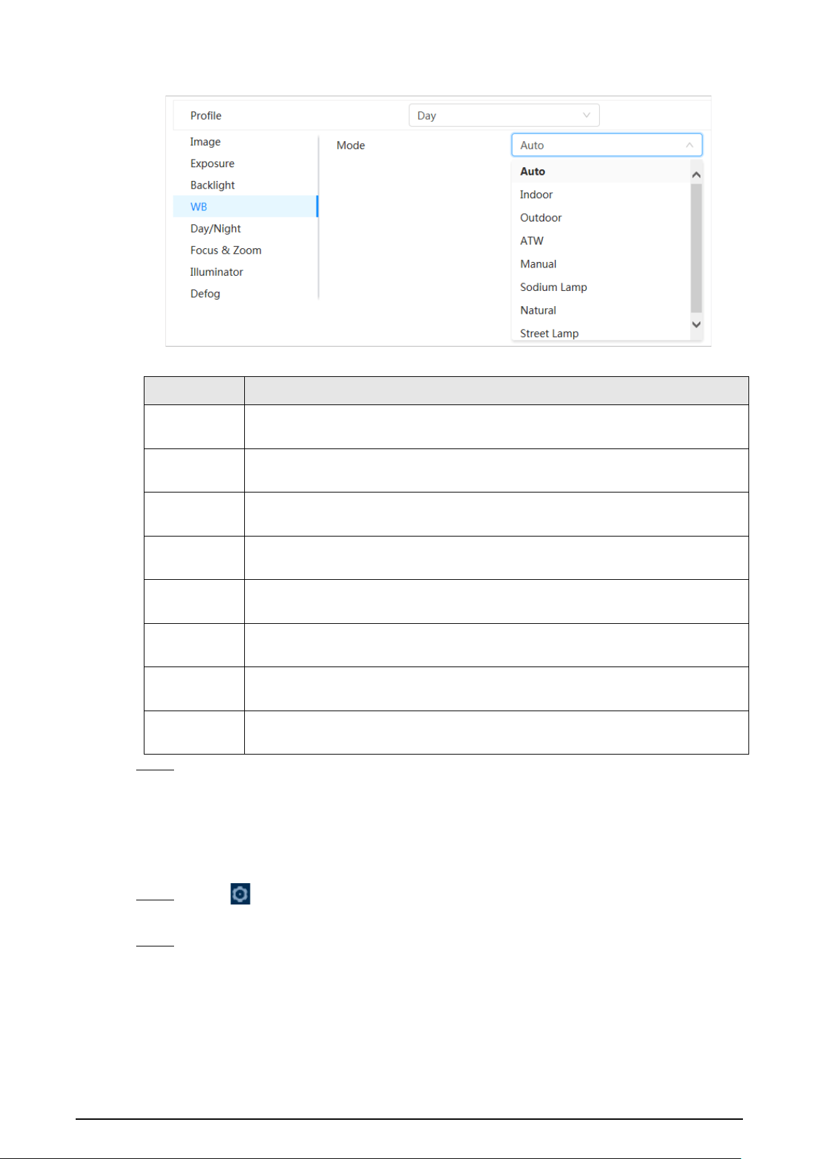
4.3.1.6 White Balance
The white balance function can correct the color deviation to ensure color precision. When in WB
mode, white objects are displayed in a white color depending on the environment.
Step 1 Click on the upper-right corner of the page, and then select
Camera
>
Image
>
WB
.
Step 2 Select the camera that needs to be configured from the
Channel
drop-down list and then
configure
White Balance Mode
.
19
Figure 4-9 White balance
Table 4-6 Description of white balance parameters
Parameter Description
Auto
The system compensates WB according to color temperature to ensure color
precision.
Indoor
The system compensates WB for the general situation of indoor lighting to
ensure color precision.
Outdoor
The system auto compensates WB to most outdoor environments with natural or
artificial light to ensure color precision.
ATW
When the device is tracked, the system auto compensates WB to ensure color
precision.
Manual
Configure red gain and blue gain manually. The system auto compensates WB
according to color temperature.
Sodium
Lamp
The system compensates WB to sodium lamp to ensure color precision.
Natural Light
The system auto compensates WB to environments without artificial light to
ensure color precision.
Street Lamp
The system compensates WB to ensure color precision in outdoor scenes at
night.
Step 3 Click
Apply
.
4.3.1.7 Day/Night
Configure the display mode of the image. The system switches between color and black-and-white
mode according to the actual condition.
Step 1 Click on the upper-right corner of the page, and then select
Camera
>
Image
>
Day/Night
.
Step 2 Select the camera that needs to be configured from the
Channel
drop-down list and then
configure parameters.

20
Figure 4-10 Day/Night mode
Table 4-7 Description of Day/Night mode parameters
Parameter Description
Mode
You can select device display mode from
Color
,
Auto
, and
B/W
.
Day/Night
configuration is independent from
Profile
management
configuration.
●
Color
: The system displays the image in color.
●
Auto
: The system switches between color and black-and-white according to
actual conditions.
●
B/W
: The system displays black-and-white image.
Sensitivity
This configuration is available only when you set
Auto
in
Mode
. You can
configure camera sensitivity when switching between color and black-and-
white mode. The higher the sensitivity, the easier it is for the switch to be
triggered.
Delay
This configuration is available only when you set
Auto
in
Mode
. You can
configure the delay when camera switching between color and black-and-white
mode. The lower the value is, the faster the camera switches between color and
black-and-white mode.
Step 3 Click
Apply
.
4.3.1.8 Focus & Zoom
Focus & Zoom (digital zoom) refers to capturing a part of the image to magnify it. The higher the
magnification is, the blurrier the images will become.
Step 1 Click on the upper-right corner of the page, and then select
Camera
>
Image
>
Focus
& Zoom
.
Step 2 Select the camera that needs to be configured from the
Channel
drop-down list and then
configure focus & zoom parameters.

21
Figure 4-11 Focus & Zoom
Table 4-8 Description of focus & zoom parameters
Parameter Description
Digital Zoom
Click to enable Digital Zoom function. You can use the
digital zoom to continue zooming operation even if the optical
zoom is at its maximum value.
Zoom Speed
Adjust the zoom speed of the camera. The larger the value, the
faster the zoom speed.
Focus Mode
Set focus mode.
●
Auto
: Once there is any movement or change of an object on
the video image and the image turns blurry, the camera will
focus again automatically.
●
Semi-Auto
: The camera will focus automatically when you
click
Focus
or
Zoom
or when a preset change or PTZ switch is
detected.
●
Manual
: The Device cannot focus automatically. You need to
adjust the focus manually.
Near Focus Limit
Set the near focus limit of the camera. If the focus limit is too small,
the camera might get the camera focus on its dome. By changing
the focus limit, the focus speed can be changed.
Sensitivity
Trigger the focusing sensitivity of the camera. The higher the
sensitivity, the easier to trigger focus.
PFA
Enable
PFA
. When moving the image, the camera automatically
focuses for a clear image.
Expert Mode
Enable
Expert mode
. Train the camera to rotate and focus on the
specified route.
Lens Initialization
Click this button, and the lens will be initialized automatically. The
lens will be extended to calibrate the zoom and focus.
Step 3 (Optional) Configure expert mode.
1) Enable
Expert mode
, click
Add
to add a new scene.

22
Figure 4-12 Expert Mode
2) Click to adjust the video screen and draw the training region on the screen.
Only supports closed model area (triangle and polygons above).
3) Double-click
Lens Magnification
to set focus magnification.
4) Click
Apply
to save settings.
5) Click
Start Scene Focusing Training
.
The scene rotates and automatically focuses to the specified position. After the training
is complete, the scene status is displayed as
Complete
.
Step 4 Click
Apply
.
4.3.1.9 Illuminator
This configuration is available only when the device is equipped with illuminator. Common
illuminators are classified into IR lights, white light, laser lights, and full-spectrum lights. Different
device models support different types of illuminators. This manual is for reference only, and might
differ from the actual page.
Step 1 Click on the upper-right corner of the page, and then select
Camera
>
Image
>
Illuminator
.
Step 2 Select the camera that needs to be configured from the
Channel
drop-down list and then
configure illuminator mode.
Figure 4-13 Illuminator

23
Table 4-9 Description of illuminator parameters
Parameter Description
Fill Light
When the camera is equipped with illuminator, it supports setting
illumination mode for illuminator, including
IR Mode
,
White Light
Mode
and
Soft Light Mode
.
●
IR Mode
: Enable the IR illuminator, and the white light is
disabled. You can only capture black and white images after
enabling this function.
●
White Light Mode
: Enable the white light, and the IR illuminator
is disabled. You can capture clear scene image after enabling this
function.
●
Soft Light Mode
: Enable both IR illuminator and white light at
the same time, and adjust the brightness of the two illuminators
to get clear images.
Mode
Manual
Adjust the brightness of illuminator manually, and then the system
will illuminate the image accordingly.
Auto
The system adjusts the illuminator intensity according to the ambient
lighting condition. Some devices support setting the brightness
upper limit and sensitivity of the illuminator.
●
Sensitivity: The higher the sensitivity setting, the higher the
brightness can turn on the illuminator when the actual scene
darkens. When the actual scene becomes bright, a higher
brightness is required to turn off the illuminator.
●
Brightness upper limit: If the filling light is too bright, the center
of the image may be overexposed. We recommend adjusting to
adjust the brightness upper limit according to the actual scene.
The value range is 0-100, and the default is 100.
SmartIR
The system adjusts the illumination intensity according to the
ambient lighting condition.
Only IR illuminator supports the smart IR mode.
Zoom
Priority
The system adjusts the illuminator intensity automatically according
to the change of the ambient light. You can configure light
Compensation
manually to fine-tune the brightness of the
illuminator.
●
When the ambient light turns darker, the system turns on the low
beam lights first, if the brightness is still not enough, it turns on
the high beam lights.
●
When the ambient light turns brighter, the system dims high
beam lights until they are off, and then the low beam lights.
●
When the focus reaches certain wide angle, the system will not
turn on high beam light in order to avoid over-exposure in short
distance.
Some devices support setting the sensitivity of the illuminator.

24
Parameter Description
Off Illuminator is off.
Step 3 Click
Apply
.
4.3.1.10 Defog
The image quality is compromised in foggy or hazy environment, and defog can be used to improve
image clarity.
Step 1 Select >
Camera
>
Image
>
Defog
.
Figure 4-14 Defog
Step 2 Configure defog parameters.
Table 4-10 Description of defog parameters
Defog Description
Manual
Configure function intensity and atmospheric light mode manually, and
then the system adjusts image clarity accordingly. Atmospheric light mode
can be adjusted automatically or manually.
Auto The system adjusts image clarity according to the actual condition.
Off Defog function is disabled.
Step 3 Click
Apply
.
4.3.2 Setting Encode Parameters
This section introduces video parameters, such as video, snapshot, overlay, ROI (region of interest)
and path.
Click
Default
, and the device is restored to default configuration. Click
Refresh
to view the latest
configuration.
4.3.2.1 Encode
Configure video stream parameters, such as compression, resolution, frame rate, bit rate type, bit
rate, I frame interval, SVC (Scalable Video Coding) and watermark.

25
Step 1 Select >
Camera
>
Encode
>
Encode
.
Figure 4-15 Encode
Step 2 Configure encode parameters.
Table 4-11 Description of encode parameters
Parameter Description
Sub Stream
Click to enable sub stream, it is enabled by default.
You can enable multiple sub streams simultaneously.
Compression
Select encode mode.
●
H.264
: It includes
H.264B
(baseline profile encode mode),
H.264
(main profile encode mode) and
H.264H
(high profile
encode mode).
Under the same image quality, the bandwidth of the three
decreases in turn.
●
H.265
: Main profile encode mode. Compared with H.264, it
requires smaller bandwidth.
●
MJPEG
: Under this mode, the image requires high bit rate to
ensure clarity, you are recommended to set the
Bit Rate
to the
biggest value in the
Reference Bit Rate
.
Smart Codec
Click to enable smart codec to improve video compressibility
and save storage space.
After smart codec is enabled, the device would stop supporting the
third bit stream, ROI, and smart event detection.
Resolution
The resolution of the video. The higher the value is, the clearer the
image will be, but the bigger the required bandwidth will be.
Frame Rate (FPS)
The number of frame in one second of video. The higher the value is,
the clearer and smoother the video will be.

26
Parameter Description
Bit Rate Type
The bit rate control type during video data transmission. You can
select bit rate type from:
●
CBR
(Constant Bit Rate): The bit rate changes a little and keeps
close to the defined bit rate value.
●
VBR
(Variable Bit Rate): The bit rate changes as monitoring
scene changes.
The
Bit Rate Type
can only be set as
CBR
when
Encode Mode
is set
as
MJPEG
.
Quality
This parameter can be configured only when the
Bit Rate Type
is set
as
VBR
. The better the quality is, but the bigger the required
bandwidth will be.
Reference Bit Rate
The most suitable bit rate value range recommended to user
according to the defined resolution and frame rate.
Max Bit Rate
This parameter can be configured only when the
Bit Rate Type
is set
as
VBR
. You can select the value of the
Max Bit Rate
according to
the
Reference Bit Rate
value. The bit rate then changes as
monitoring scene changes, but the max bit rate keeps close to the
defined value.
Bit Rate
This parameter can be configured only when the
Bit Rate Type
is set
as
CBR
. Select bit rate value in the list according to actual condition.
I Frame Interval
The number of P frames between two I frames, and the
I Frame
Interval
range changes as
FPS
changes. It is recommended to set
I
Frame Interval
twice as big as
FPS
.
SVC
Scaled video coding, is able to encode a high quality video bit
stream that contains one or more subset bit streams. When sending
stream, to improve fluency, the system will quit some data of related
lays according to the network status.
●
1: The default value, which means that there is no layered
coding.
●
2, 3 and 4: The lay number that the video stream is packed.
Watermark You can verify the watermark to check if the video has been
tampered.
●
Click to enable watermark function.
●
Enter watermark string. The string is DigitalCCTV by default.
Watermark String
Step 3 Click
Apply
.
4.3.2.2 Overlay
Configure overlay information, and it will be displayed on the
Live
page.
4.3.2.2.1 Privacy Masking
You can enable this function when you need to protect the privacy of some area on the video image.
Step 1 Select >
Camera
>
Encode
>
Privacy Masking
.
Step 2 Select
Enable
.

27
Step 3 Click
Add
, select
Color Block
or
Mosaic
, and then draw the blocks on the screen.
●
You can draw 8 blocks at most. The same screen can add up to 4 mosaic blocks.
●
Click
Clear
to delete all blocks; select the block you want to delete, click to delete
the corresponding block.
Figure 4-16 Privacy masking
Step 4 Adjust block size to protect the privacy.
Step 5 Click
Apply
.
4.3.2.2.2 Channel Title
You can enable this function when you need to display channel title in the video image.
Step 1 Select >
Camera
>
Encode
>
Overlay
>
Channel Title
.
Step 2 Select
Enable
.
Step 3 Configure channel title, and then select the text alignment.
Click
+
to add the channel title, and you can add 1 line at most.
Figure 4-17 Channel title
Step 4 Move the title box to the position that you want in the image.
Step 5 Click
Apply
.

28
4.3.2.2.3 Time Title
You can enable this function when you need to display time title in the video image.
Step 1 Select >
Camera
>
Encode
>
Overlay
>
Time Title
.
Step 2 Select
Enable
.
Step 3 (Optional) Select
Week Display
to display the day of week on the video image.
Step 4 Move the time box to the position that you want on the image.
Figure 4-18 Time title
Step 5 Click
Apply
.
4.3.2.2.4 OSD Info
If you want to represent such information in video images as preset dots, PTZ/geography location,
zoom and touring pattern, you can enable this function.
Step 1 Select >
Camera
>
Encode
>
Overlay
>
OSD Info
.
Figure 4-19 OSD info
Step 2 Configure OSD information.

29
Table 4-12 Description of OSD information parameter
Parameter Description
Presets
Select
Enable
, and the preset name is displayed on the image
when the camera turns to the preset, and it will disappear 3 s
later.
PTZ Coordinates
Select
Enable
, and the PTZ coordinates information is displayed
on the image.
Zoom
Select
Enable
and the zoom information is displayed on the
image.
North
Select
Enable
, and the north direction is displayed on the image.
When you enable the due north orientation function, the system
will prompt you to restart the PTZ.
Pattern
Select
Enable
, and the pattern information is displayed on the
image.
RS485
Select
Enable
, and the RS485 information is displayed on the
image.
Location
Select
Enable
, and the geographical location is displayed in the
text.
Text Alignment
Set the alignment mode of the displayed information on the
image.
Step 3 Move the OSD box to the position that you want on the image.
Step 4 Click
Apply
.
4.3.2.2.5 Font Properties
You can enable this function if you need to adjust the font size in the video image.
Step 1 Select >
Camera
>
Encode
>
Overlay
>
Font Properties
.
Step 2 Select the font color and size.
You can set the RGB value to customize the font color.
Figure 4-20 Font properties
Step 3 Click
Apply
to complete the settings.
After saving the settings, the color and size of the font in the video image change
accordingly.

30
4.3.2.2.6 Picture Overlay
You can enable this function if you need to display image information on the video image.
Text overlay and picture overlay cannot work at the same time.
Step 1 Select >
Camera
>
Encode
>
Overlay
>
Picture Overlay
.
Step 2 Select channel and then select
Enable
.
Step 3 Click
Upload
, and then select the overlaid image.
The image shows in the
Picture Preview
.
Figure 4-21 Picture overlay
Step 4 You can move the overlaid image to the position you want in the image.
Step 5 Click
Apply
.
4.3.2.2.7 Custom Title
You can enable this function if you need to display custom information on the video image.
Step 1 Select >
Camera
>
Encode
>
Overlay
>
Custom Title
.
Step 2 Select
Enable
.
Step 3 Configure custom overlay, and then select the text alignment.
Click
+
to add the custom overlay, and you can add 1 line at most.

31
Figure 4-22 Custom title
Step 4 Move the custom box to the position that you want in the image.
Step 5 Click
Apply
.
4.3.2.2.8 Exception Overlay
You can enable this function to display the overlaid abnormal information of the cameras on the
screen.
Step 1 Select >
Camera
>
Encode
>
Overlay
>
Exception Overlay
.
Figure 4-23 Exception overlay
Step 2 Select
Enable
, and then click
Apply
.
4.3.2.2.9 Longitude & Latitude
You can enable this function to display the latitude and longitude information of the cameras on the
screen.
Step 1 Select >
Camera
>
Encode
>
Longitude & Latitude
.

32
Figure 4-24 Longitude & latitude
Step 2 Enable
Longitude & Latitude
, and then click
Apply
.
4.3.2.2.10 Target Statistics
After configuring the target statistics, the number of target statistics will be displayed in the image.
Step 1 Select >
Camera
>
Encode
>
Target Statistics
.
Step 2 Select
Enable
.
Step 3 Select the statistics type, and then select the text alignment.
Click
Reset
to clear the statistics data.
Figure 4-25 Target statistics
Step 4 Move the target statistics box to the position that you want in the image.
Step 5 Click
Apply
.
The overlaid information will be displayed after enabling video metadata function.

33
4.3.2.2.11 Face Statistics
Procedure
Step 1 Select >
Camera
>
Encode
>
Face Statistics
.
Figure 4-26 Face statistics
Step 2 Select
Enable
, and then select
Statistics Type
.
●
Face detection: The screen displays the quantity information of face detection.
●
Face recognition: The screen displays the quantity information of face recognition.
Step 3 Select the text alignment, and then move the face statistics box to the position that you
want in the image.
Step 4 Click
Apply
.
Related Operations
Click
Reset
to clear the statistics data and start counting again.
4.3.2.3 ROI
Select ROI (region of interest) on the image and configure the image quality of ROI, and then the
selected image is display at defined quality.
Step 1 Select >
Camera
>
Encode
>
ROI
.
Step 2 Select channel, and then select
Enable
.
Step 3 Click
Add
, draw an area on the image, and then configure the image quality of ROI.
●
You can draw 4 area boxes at most.
●
The higher the image quality value is, the better the quality will be.
●
Click
Clear
to delete all the area boxes; select one box, and then click to delete it.

34
Figure 4-27 ROI
Step 4 Click
Apply
.
4.3.3 Audio
Configure the noise filter and sampling frequency of the Camera. When enabling audio encoding,
the network stream contains both audio and video, otherwise, it is only video stream.
You need to click on the upper-right corner of the page, and then select
Camera
>
Encode
>
Encode
to enable the video stream of Sub Stream before enabling the audio.
Step 1 Click on the upper-right corner of the page, and then select
Camera
>
Audio
.
Step 2 Select
Main Stream
or
Sub Stream
to enable audio encoding.
For the cameras with multiple channels, select the channel number.
Please carefully activate the audio acquisition function according to the actual
requirements of the application scenario.
Figure 4-28 Audio
Step 3 Configure audio parameters.

35
Table 4-13 Description of audio parameters
Parameter Description
Compression
Configure audio compression. The configured audio encode mode applies
to both audio and intercom. The default value is recommended.
Sampling
Frequency
Sampling number per second. The higher the sampling frequency is, the
more the sample in a second will be, and the more accuracy the restored
signal will be.
Noise Filter Enable this function, and the system automatically filters ambient noise.
Microphone
Volume
Adjusts microphone volume.
Speaker Volume Adjusts speaker volume.
Step 4 Click
Apply
.
4.4 Network
This section introduces network configuration.
4.4.1 TCP/IP
You can configure IP address and DNS (Domain Name System) server and other information
according to network planning to ensure the device is properly connected to other devices in the
network.
Prerequisites
The camera has connected to the network.
Procedure
Step 1 Select >
Network
>
TCP/IP
.
Step 2 Configure TCP/IP parameters.

36
Figure 4-29 TCP/IP
Table 4-14 Description of TCP/IP parameters
Parameter Description
Host Name
Enter the host name.
The maximum length is 32 characters.
ARP/Ping
Click to enable ARP/Ping to set IP address service. Get the
camera MAC address, and then you can change and configure the
device IP address with ARP (Address Resolution Protocol) /ping
command. This is enabled by default. During restart, you will have no
more than 2 minutes to configure the device IP address by a ping
packet with certain length, the server will be turned off in 2 minutes,
or it will be turned off immediately after the IP address is successfully
configured. If this is not enabled, the IP address cannot be configured
with ping packet.
NIC
Select the Ethernet card that need to be configured, and the default
one is
Wire
.

37
Parameter Description
Mode
The mode that the camera gets IP:
●
Static
Configure
IP Address
,
Subnet Mask
, and
Default Gateway
manually, and then click
Save
, the login page with the configured
IP address is displayed.
●
DHCP
(Dynamic Host Configuration Protocol)
When there is DHCP server in the network, select
DHCP
, and the
camera acquires IP address automatically.
MAC Address Displays host MAC (Media Access Control) address.
IP Version Select
IPv4
or
IPv6
.
IP Address
When you select
Static
as
Mode
, enter the IP address and subnet
mask according to the network plan.
●
IPv6 does not have a subnet mask.
●
The default gateway must be on the same network segment with
the IP address.
Subnet Mask
Default Gateway
Preferred DNS IP address of the preferred DNS.
Alternate DNS IP address of the alternate DNS.
Step 3 Click
Apply
.
Related Operations
Configuring IP address with ARP/Ping
1. Keep the camera that needs to be configured and the PC within the same local network, and
then get a usable IP address.
2. Get the MAC address of the camera from device label.
3. Open command editor on the PC and enter the following command.

38
Figure 4-30 Edit command
4. Restart the camera.
5. Check the PC command line, if information such as
Reply from 192.168.0.125…
is displayed, the
configuration succeeds.
6. Enter http://(IP address) in the browser address bar to log in.
4.4.2 Port
Configure the port numbers and the maximum number of users (includes web, platform client and
mobile phone client) that can connect to the device simultaneously.
Step 1 Select >
Network
>
Port
.
Step 2 Configure port parameters.
●
The configuration of
Max Connection
,
RTSP Port
,
RTMP Port
,
HTTPS Port
take effect
immediately, and others will take effect after reboot.
●
0–1024, 1900, 3800, 5000, 5050, 9999, 37776, 37780–37880, 39999, 42323 are occupied
for specific uses, do not use them.
●
Do not use the same value of any other port during port configuration.

39
Figure 4-31 Port
Table 4-15 Description of port parameters
Parameter Description
Max Connection
The max number of users (web client, platform client or mobile phone
client) that can connect to the device simultaneously. The value is 10
by default.
TCP Port Transmission Control Protocol port. The value is 37777 by default.
UDP Port User Datagram Protocol Port. The value is 37778 by default.
HTTP Port
Hyper Text Transfer Protocol Port. The value is 80 by default. If it is
configured to another value, you need to add the new port number to
the IP address when logging in to the system using a browser.

40
Parameter Description
RTSP Port
●
Real Time Streaming Protocol Port, and the value is 554 by default.
If you play live view with QuickTime, VLC (Video LAN Client) or
Blackberry smart phone, the following URL (Uniform Resource
Locator) format is available.
●
When the URL format requires RTSP, you need to specify channel
number and bit stream type in the URL, and also username and
password if needed.
●
When playing live view with Blackberry smart phone, you need to
turn off the audio, and then set the codec mode to H.264B and
resolution to CIF.
URL format example:
rtsp://username:password@ip:port/cam/realmonitor?channel=1&subty
pe=0
Among that:
●
Username: The username, such as admin.
●
Password: The password, such as admin.
●
IP: The device IP, such as 192.168.1.112.
●
Port: Leave it as default (554).
●
Channel: The channel number, which starts from 1. For example, if
you are using channel 2, then the channel=2.
●
Subtype: The bit stream type; 0 means main stream (Subtype=0)
and 1 means sub stream (Subtype=1).
Example: If you require the sub stream of channel 2 from a certain
device, then the URL should be:
rtsp://admin:[email protected]:554/cam/realmonitor?channel=21&=1
If username and password are not needed, then the URL can be:
rtsp://ip:port/cam/realmonitor?channel=11&=0
RTMP Port
Real Time Messaging Protocol Port. This is the port that RTMP provides
service. It is 1935 by default.
HTTPS Port
Hyper Text Transfer Protocol over Secure Socket Layer Port. It is 443 by
default.
Step 3 Click
Apply
.
4.4.3 PPPoE
Point-to-Point Protocol over Ethernet, is one of the protocols that device uses to connect to the
internet. Get the PPPoE username and password from the internet service provider, and then set up
network connection through PPPoE, the camera will acquire a WAN dynamic IP address.
Prerequisites
●
The camera has connected to the network.
●
You have gotten the account and password from ISP (Internet Service Provider).
Procedure
Step 1 Select >
Network
>
PPPoE
.

41
Step 2 Click , and then enter username and password.
Figure 4-32 PPPoE
●
Disable UPnP while using PPPoE.
●
After making PPPoE connection, the device IP address cannot be modified through
web page.
Step 3 Click
Apply
.
The success prompt box is displayed, and then the real-time WAN IP address is displayed.
You can visit camera through the IP address.
4.4.4 DDNS
Properly configure DDNS (Dynamic Domain Name System), and then the domain name on the DNS
server matches your IP address and the matching relation refreshes in real time. You can always
access the camera with the same domain name no matter how the IP address changes.
Prerequisites
Check the type of DNS server supported by the camera.
Procedure
Step 1 Select >
Network
>
DDNS
.
●
Third-party server might collect your device information after DDNS is enabled.
●
Register and log in to the DDNS website, and then you can view the information of all
the connected devices in your account.
Step 2 Click to enable the function.
Step 3 Configure DDNS parameters.
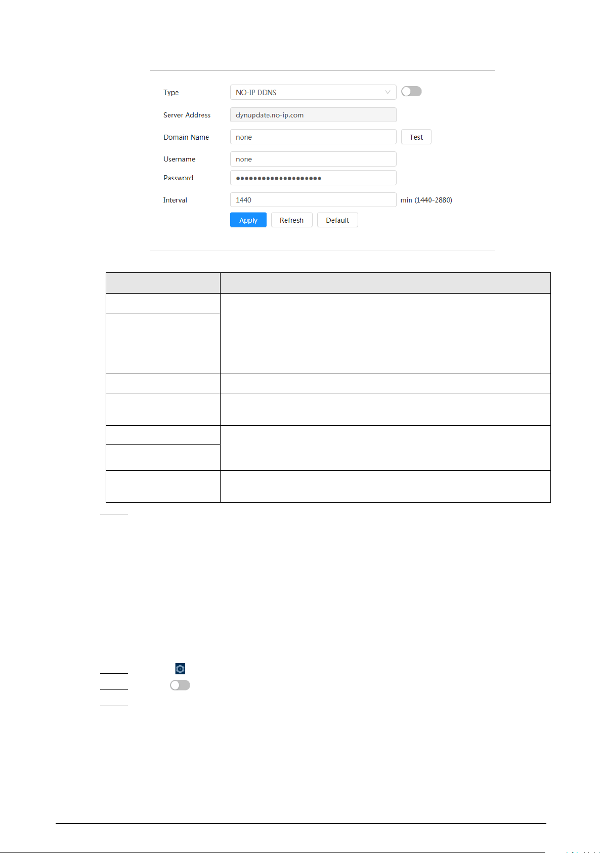
42
Figure 4-33 DDNS
Table 4-16 Description of DDNS parameters
Parameter Description
Type The name and web address of the DDNS service provider, see the
matching relationship below:
●
CN99 DDNS web address: www.3322.org
●
NO-IP DDNS web address: dynupdate.no-ip.com
●
Dyndns DDNS web address: members.dyndns.org
Server Address
Domain Name The domain name you registered on the DDNS website.
Test
Only when selecting
NO-IP DDNS
type, you can click
Test
to check
whether the domain name registration is successful.
Username Enter the username and password that you got from the DDNS server
provider. You need to register an account (includes username and
password) on the DDNS server provider's website.
Password
Interval
The update cycle of the connection between the device and the server,
and the time is 10 minutes by default.
Step 4 Click
Apply
.
Result
Open the browser on PC, enter the domain name at the address bar, and then press
Enter
, the login
page is displayed.
4.4.5 Email
Configure email parameter and enable email linkage. The system sends email to the defined address
when the corresponding alarm is triggered.
Step 1 Select >
Network
>
Email
.
Step 2 Click to enable the function.
Step 3 Configure email parameters.

43
Figure 4-34 Email
Table 4-17 Description of email parameters
Parameter Description
SMTP Server
SMTP (Simple Mail Transfer
Protocol) server address.
For details, see Table 4-18.
Port
The port number of the SMTP
server.
Username The account of SMTP server.
Password The password of SMTP server.
Anonymous Click , and the sender's information is not displayed in the email.
Sender Sender’s email address.
Encryption Type
Select from
None
,
SSL (Secure Sockets Layer)
and
TLS (Transport
Layer Security)
.
For details, see Table 4-18.
Subject
Enter maximum 63 characters in Chinese, English, and Arabic numbers.
Click to select title type, including
Device Name
,
Device ID
, and
Event Type
, and you can set maximum 2 titles.
Attachment Select the checkbox to support attachment in the email.
Receiver
●
Receiver’s email address. Supports 3 addresses at most.
●
After entering the receiver's email address, click
Test
to test
whether the emails can be sent and received successfully.

44
Parameter Description
Health Mail The system sends test mail to check if the connection is successfully
configured. Click and configure the
Sending Interval
, and then
the system sends test mail as the set interval.
Sending interval of health mail ranges from 1 second to 3,600 seconds.
Sending Interval
Table 4-18 Description of major mailbox configuration
Mailb
ox
SMTP server
Authenticat
ion
Port Description
gmail smtp.gmail.com
SSL 465
You need to enable SMTP service in
your mailbox.
TLS 587
Sina smtp.sina.com
SSL 465
None 25
126 smtp.126.com None 25
163 smtp.163.com
SSL 465/994
●
You need to enable SMTP service
in your mailbox.
●
The password should be
"Authentication Password".
Password for email login is
invalid.
Authentication Password:
Authentication Password is
obtained when the SMTP service is
enabled.
TLS 25
None 25
QQ smtp.qq.com
SSL 465 ●
None
cannot be selected for
authentication.
●
You need to enable SMTP service
in your mailbox.
●
The password should be
"Authentication Password".
Password for email login is
invalid.
Authentication Password:
Authentication Password is
obtained when the SMTP service is
enabled.
TLS 587
Step 4 Click
Apply
.
4.4.6 UPnP
UPnP (Universal Plug and Play) is a protocol that establishes mapping relation between local area

45
and wide area networks. This function enables you to visit local area device through wide area IP
address.
Prerequisites
●
Make sure the UPnP service is installed in the system.
●
Log in to the router, and then configure WAN IP address to set up internet connection.
●
Enable UPnP in the router.
●
Connect your device to the LAN port of the router.
●
Select >
Network
>
TCP/IP
, in
IP Address
, enter the local area IP address of the router or
select
DHCP
and then the system acquires IP address automatically.
Procedure
Step 1 Select >
Network
>
UPnP
.
Step 2 Click next to
Enable
, and there are two mapping modes:
Custom
and
Default
.
Figure 4-35 UPnP
●
Select
Custom
, click and then you can change external port.
●
Select
Default
, and then the system finishes mapping with unoccupied port
automatically, and you cannot edit mapping relation.
●
Select
Enable Device Discovery
to search for the device through the PC's online
neighbors. The device name is the serial number.
Step 3 Click
Apply
.
Open web browser on PC, enter http:// wide area IP address: external port number, and then
you can visit the local area device with corresponding port.
4.4.7 SNMP
SNMP (Simple Network Management Protocol) can be used to enable software such as MIB Builder
and MG-SOFT MIB Browser to connect to the camera, and then manage and monitor the camera.
Prerequisites
●
Install SNMP monitoring and managing tools such as MIB Builder and MG-SOFT MIB Browser.
●
Get the MIB file of the matched version from technical support.
Procedure
Step 1 Select >
Network
>
SNMP
.
Step 2 Select SNMP version to enable SNMP.
●
Select
V1
, and the system can only process information of V1 version.
●
Select
V2
, and the system can only process information of V2 version.

46
●
Select
V3 (Recommended)
, and then
V1
and
V2
become unavailable. You can
configure username, password and authentication type. It requires corresponding
username, password and authentication type to visit your device from the server.
Using
V1
and
V2
might cause data leakage, and
V3
is recommended.
Step 3 In
Trap Address
, enter the IP address of the PC that has MIB Builder and MG-SOFT MIB
Browser installed, and leave other parameters as default.
Figure 4-36 SNMP (1)

47
Figure 4-37 SNMP (2)
Table 4-19 Description of SNMP parameters
Parameter Description
SNMP Port The listening port of the software agent in the device.
Read Community The read and write community string that the software agent
supports.
You can enter number, letter, underline and dash to form the
name.
Write Community
Trap Address
The target address of the Trap information sent by the software
agent in the device.
Trap Port
The target port of the Trap information sent by the software agent
in the device.
Read-only Username
Set the read-only username accessing device, and it is
public
by
default.
You can enter number, letter, and underline to form the name.

48
Parameter Description
Read/Write Username
Set the read/write username access device, and it is
private
by
default.
You can enter number, letter, and underline to form the name.
Authentication Type You can select from
MD5
and
SHA
. The default type is
MD5
.
Authentication Password It should be no less than 8 digits.
Encryption Type The default is CBC-DES.
Encryption Password It should be no less than 8 digits.
Step 4 Click
Apply
.
Result
View device configuration through MIB Builder or MG-SOFT MIB Browser.
1. Run MIB Builder and MG-SOFT MIB Browser.
2. Compile the two MIB files with MIB Builder.
3. Load the generated modules with MG-SOFT MIB Browser.
4. Enter the IP address of the device you need to manage in the MG-SOFT MIB Browser, and then
select version to search.
5. Unfold all the tree lists displayed in the MG-SOFT MIB Browser, and then you can view the
configuration information, video channel amount, audio channel amount, and software version.
Use PC with Windows and disable SNMP Trap service. The MG-SOFT MIB Browser will display prompt
when alarm is triggered.
4.4.8 Bonjour
Enable this function, and the OS and clients that support Bonjour would find the camera
automatically. You can have quick visit to the camera with Safari browser. When the device is
automatically detected by Bonjour, the name is displayed as the defined server name.
Bonjour is enabled by default.
Procedure
Step 1 Select >
Network
>
Bonjour
.
Step 2 Click , and then configure server name.
Figure 4-38 Bonjour
Step 3 Click
Apply
.

49
Result
In the OS and clients that support Bonjour, follow the steps below to visit the network camera with
Safari browser.
1. Click
Show All Bookmarks
in Safari.
2. Enable
Bonjour
. The OS or client automatically detects the network cameras with Bonjour
enabled in the LAN.
3. Click the camera to visit the corresponding web page.
4.4.9 Multicast
When multiple users are viewing the device video image simultaneously through network, it might
fail due to the limited bandwidth. You can solve this problem by setting up a multicast IP (224.0.0.0–
239.255.255.255) for the camera and adopt the multicast protocol.
Step 1 Select >
Network
>
Multicast
.
Step 2 Click , and then enter IP address and port number.
Figure 4-39 Multicast
Table 4-20 Description of multicast parameters
Parameter Description
Multicast Address
The multicast IP address of
Main Stream
/
Sub Stream
is 224.1.2.4
by default, and the range is 224.0.0.0–239.255.255.255.
Port
The range of multicast port is 1025–65500.
●
Single-channel device: The multicast port of corresponding
stream:
Main Stream
: 40000;
Sub Stream1
: 40016;
Sub
Stream2
: 40032.
●
Multi-channel device:
1. Channel 1: The multicast port of corresponding stream:
Main Stream
: 40000;
Sub Stream1
: 40016;
Sub Stream2
:
40032.
2. Channel 2: The multicast port of corresponding stream:
Main Stream
: 40048;
Sub Stream1
: 40064;
Sub Stream2
:
40080.
3. Channel 3: The multicast port of corresponding stream:
Main Stream
: 40096;
Sub Stream1
: 40112;
Sub Stream2
:
40128.
4. Channel 4: The multicast port of corresponding stream:
Main Stream
: 40144;
Sub Stream1
: 40160;
Sub Stream2
:
40176.
Step 3 Click
Apply
.

50
Result
●
In the web page, click and then select
local
. In the
Play Parameter
area, select
Protocol
as
Multicast.
●
Click
Live
on the main page of the web page, and then monitor the video image of
corresponding stream in a multicast form on the
Live
page.
4.4.10 Register
After you enable this function, when the camera is connected into Internet, it will report the current
location to the specified server which acts as the transit to make it easier for the client software to
access the camera.
Step 1 Select >
Network
>
Register
.
Step 2 Click , and then configure
Server Address
,
Port
and
Sub-Device ID
.
Figure 4-40 Register
Table 4-21 Description of register parameters
Parameter Description
Server Address The IP address or domain name of the server to be registered.
Port The port number of the server to be registered.
Sub-Device ID The custom ID for the camera.
Step 3 Click
Apply
.
4.4.11 QoS
You can solve problems such as network delay and congestion with QoS (Quality of Service)
function. It helps to assure bandwidth, reduce transmission delay, packet loss rate, and delay jitter to
improve experience.
Step 1 Select >
Network
>
QoS
.
Step 2 Configure QoS parameters.

51
Figure 4-41 QoS
Table 4-22 Description of QoS parameters
Parameter Description
Real-time Monitoring
Configure the priority of the data packets that used for network
surveillance. 0 for the lowest and 63 the highest.
Operation Command
Configure the priority of the data packets that are used for configure
or checking. 0 for the lowest and 63 the highest.
Step 3 Click
Apply
.
4.4.12 Cellular Network
After the device is installed with the Subscriber Identification Module (SIM) card, the device can be
connected to the 5G network through dial-up settings or mobile settings, and then you can remotely
preview the real-time video of the device through the platform client or mobile phone client.
●
Dial-up setting: Connects the device to the 5G network within a specified time period.
●
Mobile setting: Connects the device to the 5G network by sending messages or making calls
through mobile phones, and alarm information can be received through messages.
4.4.12.1 Dial-up Settings
Connects the device to the 5G network through dial-up settings.
Step 1 Select >
Network
>
Cellular Network
>
Dial-up
.
After the SIM card is installed, the module information, network status and network signal
are displayed.
Step 2 Select
Network Type
, and then click to enable the 5G dial-up function.

52
Figure 4-42 Dial-up Setting
Step 3 Configure dial-up parameters.
Table 4-23 Description of dial-up setting parameters
Parameter Description
Network Type
The network types are as follows:
●
4G (TD-LTE)
: Dial (For China Mobile/Telecom/Unicom SIM
card).
●
4G (FDD-LTE)
: Dial (For Telecom/Unicom SIM card).
●
Auto
: We recommend you use the auto mode, and then the
system automatically selects the signal type.
●
5G (NR)
: Dial, text, call (For China Mobile/Telecom/Unicom
special network card).
APN
For ordinary cards, the APN (Access Point Name) of telecom is ctlte,
the mobile is cmnet, and the Unicom is 3gnet. The APN of special
network cards varies from card to card.
Authentication Type
For ordinary cards, the authentication type of telecom is CHAP
(Challenge Handshake Authentication Protocol) or PAP (Password
Authentication Protocol). The mobile and Unicom have no
authentication type. The authentication type of special network
cards varies from card to card.
Dial-up No.
For ordinary cards, the dial-up number of telecom is #777, the
mobile is *98*1#, and the Unicom is *99#. The dial-up number of
special network cards varies from card to card.

53
Parameter Description
Username
For ordinary cards, the username of telecom is [email protected] or
card. The mobile and Unicom have no username. The username of
special network cards varies from card to card.
Password
For ordinary cards, the password of telecom is vnet.mobi or card.
The mobile and Unicom have no password. The password of special
network cards varies from card to card.
Keep Alive Interval
It refers to the connection time for the mobile user to activate the
device to access the 5G network outside the set time period. The
default value is 30 seconds, and the value ranges from 0 seconds to
7,200 seconds. After the
Keep Alive Interval
ends, the device
actively disconnects the network to achieve the purpose of saving
traffic.
Schedule
Configure the dial-up time period, and then the device will connect
to the 5G network within this specified time period. If the added
schedule does not meet requirements, click
Add Schedule
to add a
new schedule. For details, see "4.6.1.2.1 Adding Schedule".
Network
Status
Dial-up
Status
After the dial-up succeeds, the obtained information, such as the IP
address, is displayed.
●
IMSI: Displays international mobile subscriber identity.
●
IMEI: Displays international mobile equipment identity.
●
ICCID: Displays integrate circuit card identity.
SIM Status
Working
Mode
IP Address
Subnet Mask
Default
Gateway
Frequency
Band
IMSI
IMEI
ICCID
Step 4 Click
Apply
.
4.4.12.2 Mobile Settings
Connects the device to the 5G network by sending messages or making calls through mobile
phones, and alarm information can be received through messages.
●
Send SMS: Set the mobile phone number of the receiver, and then all kinds of alarms can be
linked with the Platform to send alarm SMS to the receiver.
●
Activate by SMS: Set the mobile phone number of the sender, and the sender can send an
activation command SMS to the device to enable the device to connect to the network,
disconnect from the network, or reboot.
◇
Send SMS command "on": means to connect the device to the network.
◇
Send SMS command "off": means to disconnect the device from the network.
◇
Send SMS command "reboot": means to reboot the device.
●
Activate by phone: Set the mobile phone of the caller, and then the caller can call the device and

54
activate the device to access the network.
Step 1 Select >
Network
>
Cellular Network
>
Mobile
.
Step 2 Enable
Send SMS
,
Activation by SMS
, or
Activation by phone
according to actual needs.
Figure 4-43 Mobile Setting
Step 3 Enter the phone numbers of receiver, sender and caller, and then click
Add
to add the
mobile phone users to the list.
●
Click to delete the user number.
●
When setting SMS, you can modify the title of the SMS message.
Step 4 Click
Apply
.
4.4.13 Platform Access
4.4.13.1 P2P
P2P (peer-to-peer) technology enables users to manage devices easily without requiring DDNS, port
mapping or transit server.
Scan the QR code with your smartphone, and then you can add and manage more devices on the
mobile phone client.
Step 1 Select >
Network
>
Platform Access
>
P2P
.

55
Figure 4-44 P2P
●
When P2P is enabled, remote management on device is supported.
●
When P2P is enabled and the device accesses to the network, the status shows online.
The information of the IP address, MAC address, device name, and device SN will be
collected. The collected information is for remote access only. You can cancel
Enable
selection to reject the collection.
Step 2 Log in to mobile phone client and tap
Device management
.
Step 3 Tap
+
at the upper-right corner.
Step 4 Scan the QR code on the
P2P
page.
Step 5 Follow the instructions to finish the settings.
4.4.13.2 ONVIF
The ONVIF verification is enabled by default, which allows the network video products (including
video recording device and other recording devices) from other manufacturers to connect to your
device.
ONVIF is enabled by default.
Step 1 Select >
Network
>
Platform Access
>
ONVIF
.
Step 2 Click next to
Login Verification
.
Figure 4-45 ONVIF
Step 3 Click
Apply
.

56
4.4.13.3 RTMP
Through RTMP, you can access a third-party platform (such as Ali and YouTube) to realize video live
view.
●
RTMP can be configured by admin only.
●
RTMP supports the H.264, H.264 B and H.264H video formats, and the AAC (Advanced Audio
Coding) audio format only.
Step 1 Select >
Network
>
Platform Access
>
RTMP
.
Step 2 Click .
Make sure that the IP address is trustable when enabling RTMP.
Step 3 Configure RTMP parameters.
Figure 4-46 RTMP
Table 4-24 Description of RTMP parameters
Parameter Description
Stream Type
The stream for live view. Make sure that the video format is H.264,
H.264 B or H.264H, and the audio format is AAC.
Address Type
●
Non-custom
: Enter the server IP and domain name.
●
Custom
: Enter the path allocated by the server.
Encryption Click to enable encryption function.
IP Address
When selecting
Non-custom
, you need to enter server IP address
and port.
●
IP address
: Support IPv4 or domain name.
●
Port
: Keep the default value.
Port
Custom Address
When selecting
Custom
, you need to enter the path allocated by
the server.
Step 4 Click
Apply
.

57
4.4.14 Basic Service
Configure the IP hosts (devices with IP address) that are allowed to visit the device. Only the hosts in
the trusted sites list can log in to the web page. This is to enhance network and data security.
Step 1 Select >
Network
>
Basic Service
.
Step 2 Enable the basic service according to the actual needs.
Figure 4-47 Basic service
Table 4-25 Description of basic service parameters
Parameter Description
SSH
You can enable SSH (Secure Shell) authentication to perform
safety management. This function is disabled by default.
Multicast/Broadcast Search
Enable this function, and then when multiple users are viewing
the device video image simultaneously through network, they
can find your device with multicast/broadcast protocol.
CGI
Enable this function, and then other devices can access through
this service. The function is enabled by default. CGI: Common
Gateway Interface.
ONVIF
Genetec
Mobile Push Notification
Enable this function, and then alarm capture picture triggered by
the Camera is sent to your mobile phone. This is enabled by
default.
Private Protocol
Authentication Mode
Select the authentication mode from
Security Mode
and
Compatible Mode
. Security mode is recommended.
RTSP Login Mode
Compatible with the old platform login mode. The default is
digest mode.
Step 3 Click
Apply
.

58
4.5 PTZ
This section introduces the configuration of PTZ parameters, such as preset, tour, and PTZ speed.
●
The panorama camera channel and the detail camera channel support different functions, and
might differ from the actual page.
●
Some models of panorama camera channels do not support focus, zoom and iris adjustment
functions, and might differ from the actual page.
You can enter the page of
PTZ
through two methods. The following content of the chapter uses the
button entry from the upper right corner of the page as an example.
●
Click
PTZ
on the main web page.
●
Click on the upper right corner of the page, and then click
PTZ
.
4.5.1 Configuring Presets
The camera saves parameters (such as current status of PTZ pan/tilt, focus) to the memory, so that
you can quickly call these parameters and adjust the PTZ to the correct position.
Procedure
Step 1 Click and then select
PTZ
>
Preset
.
Step 2 Set step length and click the direction buttons to adjust PTZ Direction. Click the
to adjust zoom, focus and iris to adjust the camera to the proper
position.
Step 3 Click
Add Preset
.
Add the current position to be a preset, and the preset is displayed in preset list.
Figure 4-48 Add preset
Step 4 Double-click
Preset Title
to change the name of the corresponding preset in the screen.
Step 5 Click to save the preset.
Related Operations
●
Delete preset: Click to delete corresponding preset.
●
Clear all presets: Click
Clear
to delete all added presets.

59
4.5.2 Configuring Tour
Configure Tour and the PTZ camera repeats performing tours among the configured presets after
configuration.
Prerequisites
You need to setup several preset points in advance.
Procedure
Step 1 Click and then select
PTZ
>
Tour
.
Step 2 Click
Add Tour Group
, and then double click
Name
to change the name of tour.
Step 3 Select tour group and then select the presets from the
Preset Point
drop-down list on the
left.
Repeat this step to add several presets for the tour group.
Step 4 Configure
Stay Time(S)
and
Speed
to set the stay time of the Camera at the preset point
and its rotating speed.
Stay time is measured in seconds. The value ranges from 15 seconds to 3600 seconds.
Figure 4-49 Tour group
Step 5 Select Tour mode.
●
Original Path: The camera rotates in the order of selected preset points.
●
Shortest path: The camera rearranges the preset points according to distance, and then
rotates them according to the shortest path.
This function is available on select models.
Step 6 Click
Apply
to complete settings.
Step 7 Click to start tour.
●
The ongoing tour stops if any operation is made to the PTZ.
●
Click to stop tour.

60
Related Operations
●
Delete tour group: Click to delete corresponding tour group.
●
Clear all tour groups: Click
Clear
to delete all added tour groups.
4.5.3 Configuring Scan
Scan means the Camera moves horizontally at a certain speed between the defined left and right
boundaries.
Procedure
Step 1 Click and then select
PTZ
>
Scan
.
Step 2 Click
Add Scan
, and then double click
Name
to change the name of scan.
Step 3 Configure the left and right boundaries of the scan.
1) Adjust the direction of the camera to the left edge of the scan and click on the
Left
Limit
to set the current position to the
Left Limit
of the camera.
2) Adjust the direction of the camera to the right edge of the scan and click on the
Right Limit
to set the current position to the
Right Limit
of the camera.
Figure 4-50 Scan
Step 4 Click to start scanning.
Click to stop scanning.
Related Operations
●
Delete scan: Click to delete corresponding scan.
●
Clear all scans: Click
Clear
to delete all added scans.
4.5.4 Configuring Pattern
Pattern records a series of operations that makes to the Camera. The operations include horizontal
and vertical movements, zoom and preset calling. After recording and saving the operations, you
can call the pattern path directly.
Procedure
Step 1 Click and then select
PTZ
>
Pattern
.
Step 2 Click
Add Pattern
, and then double click
Name
to change the name of pattern.
Step 3 Click to adjust the direction, focus, zoom and other parameters according to actual
needs.
Step 4 Click to complete records.

61
Figure 4-51 Pattern
Step 5 Click to start pattern.
Click to stop pattern.
Related Operations
●
Delete pattern: Click to delete the corresponding pattern.
●
Clear all patterns: Click
Clear
to delete all added patterns.
4.5.5 Configuring Pan
Pan refers to the continuous 360° rotation of the Camera in a horizontal way at a certain speed.
Step 1 Click , and then select
PTZ
>
Pan
.
Step 2 Configure the rotation speed.
●
Click
Start
and PTZ starts horizontal rotation.
●
Click
Stop
to stop the pan.
Figure 4-52 Pan
4.5.6 Configuring PTZ Speed
Configure the rotation speed when manually controlling the PTZ.
Step 1 Click and then select
PTZ
>
PTZ Speed
.

62
Figure 4-53 PTZ Speed
Step 2 Select PTZ speed, and then click
Apply
.
4.5.7 Configuring Idle Motion
Idle motion refers to a preset motion when the PTZ does not receive any valid command within a
certain period.
Prerequisites
You have set PTZ motions such as preset, tour, scan and pattern in advance.
Procedure
Step 1 Click and then select
PTZ
>
PTZ Speed
.
Step 2 Click to enable idle motion.
Step 3 Configure idle interval time, and then select idle motion type.

63
Figure 4-54 Idle motion
Step 4 Click
Apply
.
4.5.8 Configuring Power Up
After configuring PowerUp, the camera will automatically perform the set motion after being
powered up.
Prerequisites
You have set PTZ motions such as preset, tour, scan and pattern in advance.
Procedure
Step 1 Click and then select
PTZ
>
PowerUp
.
Step 2 Click to enable PowerUp function.
Step 3 Select PowerUp type.
Select
Auto
and the system will implement the last action performed for more than 20
seconds before the Camera is shut down.

64
Figure 4-55 PowerUp
Step 4 Click
Apply
.
4.5.9 Configuring PTZ Rotation Limit
Configure PTZ rotation limit to enable the Camera to move only within the defined PTZ area, and to
rotate only within the limit range when calling functions such as tour and pan.
Step 1 Click and then select
PTZ
>
PTZ Rotation Limit
.
Step 2 Adjust the device direction to the
Up Limit
, and then click up limit
Setting
to set the
current position to the up limit.
Step 3 Adjust the device direction to the
Down Limit
, and then click down limit
Setting
to set the
current position to the down limit.
Step 4 Click
Go to
to preview the defined up/down limit.

65
Figure 4-56 PTZ rotation limit
Step 5 Select the elevation value from the drop-down list of
Max Elevation Angle
.
This function is available on select models.
Step 6 Click
Enable
to enable
PTZ Rotation Limit
.
4.5.10 Configuring Scheduled Task
After setting scheduled task, the Camera performs the relevant motions during the set period.
Prerequisites
You have set PTZ motions such as preset, tour, scan and pattern in advance.
Procedure
Step 1 Click and then select
PTZ
>
Scheduled Task
.
Step 2 Click
Add Scheduled Task
.
Step 3 Select
Task Action
.
Some task actions need to select corresponding action number.
Step 4 Select
Time Plan
or click
Add Schedule
. Configure the name and time of the scheduled
task in the pop-up page, and then click
Apply
.
To configure arming/disarming period, see"4.6.1.2.1 Adding Schedule".

66
Figure 4-57 Scheduled task
Step 5 Set the time for
Auto Home
.
Auto Home
: When the scheduled task is interrupted by an artificial call to the PTZ, the
device will automatically resume the scheduled task after the auto home time.
Step 6 Click
Apply
.
4.5.11 Configuring PTZ Maintenance
PTZ Maintenance includes
PTZ Restart
and
Default
.
Step 1 Click and then select
PTZ
>
PTZ Maintenance
.
Step 2 Click
PTZ Restart
to restart PTZ or click
Default
to restore PTZ to defaults.
Default PTZ will restore the Camera to defaults. Think twice before clicking
Default
.
4.5.12 Configuring Protocol
Configure parameters for RS-485.
Step 1 Click and then select
PTZ
>
Protocol
.

67
Figure 4-58 Configure protocol
Step 2 Click
Apply
.
4.6 Event
Click
Event
to configure general events, including alarm linkage, exception, video detection, and
audio detection.
You can go to the
Event
page through two methods. This following section uses method 1 as an
example.
●
Method 1: Click on the right-upper corner of the main page, and then click
Event
.
●
Method 2: Click
Event
on the page.
4.6.1 Setting Alarm Linkage
4.6.1.1 Setting Alarm-in
When an alarm is triggered by the device connected to the alarm-in port, the system performs the
defined alarm linkage.
Step 1 Select >
Event
>
Alarm
.
Step 2 Click next to
Enable
to enable alarm linkage.

68
Figure 4-59 Alarm linkage
Step 3 Select an alarm-in port and a sensor type.
●
Anti-Dither
: Only record one alarm event during the anti-dither period.
●
Sensor Type:
NO
or
NC
.
Step 4 Select the schedule and arming periods and alarm linkage action. For details, see "4.6.1.2
Alarm Linkage".
If the exiting schedules cannot meet the scene requirement, you can click
Add Schedule
to add new schedule. For details, see "4.6.1.2.1 Adding Schedule".
Step 5 Click
Apply
.
4.6.1.2 Alarm Linkage
When configuring alarm events, select alarm linkages (such as record, snapshot). When the
corresponding alarm is triggered in the defined arming period, the system will trigger alarm linkage.
Select >
Event
>
Alarm
, and then click next to
Enable
to enable alarm linkage.

69
Figure 4-60 Alarm linkage
4.6.1.2.1 Adding Schedule
Configure arming schedule. The system only performs corresponding linkage action in the defined
period.
Step 1 Click
Add Schedule
next to
Schedule
.
Step 2 Click
Time Plan Table
.
You can set up multiple time plan tables for selection.
Step 3 Configure the name of the
Time Plan Table
.
Step 4 Configure arming periods.
1) Press and drag the left mouse button on the timeline to set arming periods. The green
area on the timeline means that this time period has been armed.

70
Figure 4-61 Configuring arming period
2) Click the selected time period, and then enter the specific time in the text box to
configure exact arming period.
Figure 4-62 Configuring exact arming period
Step 5 (Optional) Click
Copy
, select weeks, and then click
Apply
.
Time plans for the current week can be quickly copied to other weeks.
Step 6 Click
Apply
.
4.6.1.2.2 Record Linkage
After enabling
Record Linkage
, the system can link record channel when an alarm event occurs.
After the alarm, the system stops recording after an extended time period according to the
Post-
Record
setting.

71
Prerequisites
●
Enable the corresponding alarm type (
Normal
,
Motion
, or
Alarm
) before the record channel
links recording. For details, see "6.3 Setting Record Plan".
●
Enable auto record mode before the record linkage takes effect. For details, see "6.2 Setting
Record Control".
Setting Record Linkage
On the
Alarm
page, click to enable record linkage, select the channel, and then set
Post-
Record
to set alarm linkage and record delay.
After
Post-Record
is configured, alarm recording continues for an extended period after the alarm
ends.
Figure 4-63 Record linkage
4.6.1.2.3 Snapshot Linkage
After snapshot linkage is configured, the system can automatically alarm and take snapshots when
an alarm is triggered.
Prerequisites
Enable the corresponding alarm type (
Normal
,
Motion
, or
Alarm
) before the snapshot channel links
capturing. For details, see "6.3 Setting Record Plan".
Setting record linkage
On the
Alarm
page, click to enable snapshot linkage, and select the channel
Figure 4-64 Snapshot linkage
4.6.1.2.4 Alarm-out Linkage
When an alarm is triggered, the system can automatically link with alarm-out device.
On the
Alarm
page, click to enable alarm-out linkage, select the channel and then configure
Post alarm
.
When alarm delay is configured, alarm continues for an extended period after the alarm ends.
If the Camera has multiple alarm-out channels, you need to select the linkage alarm-out channel.
Figure 4-65 Alarm-out linkage

72
4.6.1.2.5 Email Linkage
When an alarm is triggered, the system will automatically send an email to defined users.
Prerequisites
Email linkage takes effect only when SMTP is configured. For details, see "4.4.5 Email".
Setting Email Linkage
On the
Alarm
page, click to enable email linkage.
Figure 4-66 Email linkage
4.6.1.3 Alarm Linkage
When configuring alarm events, select alarm linkages (such as record, snapshot). When the
corresponding alarm is triggered in the defined arming period, the system will trigger alarm linkage.
Step 1 Select >
Event
>
Alarm
, and then click next to
Enable
to enable alarm
linkage.
Step 2 Click
Apply
.
Figure 4-67 Alarm linkage

73
4.6.1.4 Subscribing to Alarm
4.6.1.4.1 Alarm Types
Following are the alarm types and preparations of alarm events.
Table 4-26 Description of alarm types
Alarm Type Description Preparation
Motion Detection
The alarm is triggered when a
moving object is detected.
Motion detection is enabled. For
details, see "4.6.3.1 Setting Motion
Detection".
Disk Full
The alarm is triggered when the
free space of SD card is less than
the configured value.
Insufficient SD card space detection
is enabled. For details, see "4.6.2.1
Setting SD Card Exception".
Disk Error
The alarm is triggered when
there is a failure or malfunction
in the SD card.
SD card failure detection is enabled.
For details, see "4.6.2.1 Setting SD
Card Exception".
Video Tampering
The alarm is triggered when the
camera lens is covered or there is
a defocus in video images.
Video tampering is enabled. For
details, see "4.6.3.2 Setting Video
Tampering".
External Alarm
The alarm is triggered when
there is an external alarm input.
The device has alarm input port
and external alarm function is
enabled. For details, see "4.6.1.1
Setting Alarm-in".
Security Warning
The alarm is triggered when
there is a security warning.
Security warning is enabled. For
details, see "9.6 Security Warning"
Audio Detection
The alarm is triggered when
there is an audio connection
problem.
Abnormal audio detection is
enabled. For details, see "4.6.4
Setting Audio Detection".
IVS
The alarm is triggered when an
intelligent rule is triggered.
IVS, face detection, people
counting, or other intelligent
functions is enabled.
Scene Changing
The alarm is triggered when the
device monitoring scene
changes.
Scene changing detection is
enabled. For details, see "4.6.3.3
Setting Scene Changing".
Voltage Detection
The alarm is triggered when the
device detects abnormal voltage
input.
Voltage detection is enabled. For
details, see "4.6.2.3 Setting
Tampering Detection".
Security Exception
The alarm is triggered when the
device detects malicious attack.
Voltage detection is enabled. For
details, see "9.1 Security Status".
4.6.1.4.2 Subscribing to Alarm Information
You can subscribe alarm event. When a subscribed alarm event is triggered, the system records
detailed alarm information on the bottom of the page.
Functions of different devices might vary.
Step 1 Click on the right-upper corner of the main page.

74
Step 2 Click next to
Alarm
to enable alarm subscription, and then the system prompts and
records alarm information according to actual conditions.
●
When the subscribed alarm event is triggered and the alarm subscription page is not
displayed, a number is displayed on , and the alarm information is recorded
automatically. Click to view the details in the alarm list. You can click
Clear
to clear
the record.
●
When the subscribed alarm event is triggered and the system is in the alarm page, the
corresponding alarm information will be displayed in the alarm list below.
Figure 4-68 Alarm (subscription)
Step 3 Click next to
Play Alarm Tone
, and then select the tone path.
The system will play the selected audio file when the subscribed alarm is triggered.
4.6.2 Setting Exception
Abnormality includes SD card exception, network exception and tampering detection.
Only the device with SD card function has exception setting functions, including
No SD Card
,
SD
Card Error
, and
Low SD card space
.
4.6.2.1 Setting SD Card Exception
In case of SD card exception, the system performs alarm linkage. The event types include
No SD

75
Card
,
Low SD Card Space
, and
SD Card Error
. Functions might vary with different models.
Step 1 Select >
Event
>
Exception
>
SD Card Exception
.
Step 2 Select event type, and then enable SD card exception detection.
When the event type is
Low SD card space
, you can configure
Free Space
. When the
remaining free space is less than this value, an alarm is triggered.
Figure 4-69 SD card exception
Step 3 Click to enable the SD card detection functions.
When
Low SD Card Space
is enabled, set
Capacity Limit
. When the remaining space of SD
card is less than this value, the alarm is triggered.
Step 4 Set alarm linkage actions. For details, see "4.6.1.2 Alarm Linkage".
Step 5 Click
Apply
.
4.6.2.2 Setting Network Exception
In case of network exception, the system performs alarm linkage. The event types include
Offline
and
IP Conflict
.
Step 1 Select >
Event
>
Exception
>
Network Exception
.

76
Figure 4-70 Network exception
Step 2 Click to enable the network exception detection.
Step 3 Set alarm linkage actions. For details, see "4.6.1.2 Alarm Linkage".
Step 4 Click
Apply
.
4.6.2.3 Setting Tampering Detection
Step 1 Select >
Event
>
Exception
>
Tampering Detection
.
Step 2 Click to enable the tampering detection function.
Step 3 Configure alarm parameters.

77
Figure 4-71 Setting tampering detection
Step 4 Click
Apply
.
4.6.3 Setting Video Detection
Check whether there are considerable changes on the video by analyzing video images. In case of
any considerable change on the video (such as moving object, fuzzy image), the system performs an
alarm linkage.
4.6.3.1 Setting Motion Detection
The system performs an alarm linkage when a moving object appears in the image and its moving
speed reaches the defined sensitivity.
●
If you enable motion detection and smart motion detection simultaneously, and configure the
linked activities, the linked activities take effect as follows:
◇
When motion detection is triggered, the camera will record videos and take snapshots, but
other configured linkages such as sending emails, PTZ operation will not take effect.
◇
When smart motion detection is triggered, all the configured linkages take effect.
●
If you only enable motion detection, all the configured linkages take effect when motion
detection is triggered.
Step 1 Select >
Event
>
Video Detection
>
Motion Detection
.

78
Figure 4-72 Motion detection
Step 2 Click to enable the motion detection function.
Step 3 Set the area for motion detection.
1) Click
Setting
next to
Area
.
Figure 4-73 Area
2) Select a color and set the region name. Select an effective area for motion detection in
the image and set
Sensitivity
and
Threshold
.
●
Select a color on to set different detection parameters for each

79
region.
●
Sensitivity: Sensitive degree of outside changes. The higher sensitivity is, the easier
to trigger the alarm.
●
Threshold: Effective area threshold for Motion Detection. The smaller the threshold
is, the easier the alarm is triggered.
●
The whole video image is the effective area for Motion Detection by default. Select
color blocks to configure different detection parameters for different regions.
●
The red line in the waveform indicates that the Motion Detection is triggered, and
the green line indicates that there is no motion is detected. Adjust sensitivity and
threshold according to the waveform.
3) Click
OK
.
Step 4 Set arming periods and alarm linkage action. For details, see "4.6.1.2 Alarm Linkage".
If the exiting schedules cannot meet the scene requirement, you can click
Add Schedule
to add a new schedule. For details, see "4.6.1.2.1 Adding Schedule".
Anti-dither: After the
Anti-dither
time is set, the system only records one motion detection
event in the period.
Step 5 Click
Apply
.
4.6.3.2 Setting Video Tampering
The system performs alarm linkage when the lens is covered or video output is mono-color caused
by light and other reasons.
Step 1 Select >
Event
>
Video Detection
>
Video Tampering
.
Step 2 Select
Channel
and then click to enable the video tampering detection.
Figure 4-74 Video tampering
Step 3 Set arming periods and alarm linkage action. For details, see "4.6.1.2 Alarm Linkage".
If the exiting schedules cannot meet the scene requirement, you can click
Add Schedule

80
to add a new schedule. For details, see "4.6.1.2.1 Adding Schedule".
Anti-dither: After the
Anti-dither
time is set, the system only records one motion detection
event in the period.
Step 4 Click
Apply
.
4.6.3.3 Setting Scene Changing
The system performs alarm linkage when the image switches from the current scene to another one.
Step 1 Select >
Event
>
Video Detection
>
Scene Changing
.
Step 2 Select
Channel
and then click to enable the scene changing detection.
Figure 4-75 Scene changing
Step 3 Set arming periods and alarm linkage action. For details, see "4.6.1.2 Alarm Linkage".
If the exiting schedules cannot meet the scene requirement, you can click
Add Schedule
to add a new schedule. For details, see "4.6.1.2.1 Adding Schedule".
Anti-dither: After the
Anti-dither
time is set, the system only records one motion detection
event in the period.
Step 4 Click
Apply
.
4.6.4 Setting Audio Detection
The system performs alarm linkage when vague voice, tone change, or rapid change of sound
intensity is detected.
Step 1 Select >
Event
>
Audio Detection
.
Step 2 (Optional) Select audio channels.
When the camera supports multiple audio channels, you can select different audio
channels.
Step 3 Configure parameters of audio detection.
●
Input abnormal: Click to enable
Audio Exception
, and the alarm is triggered

81
when the system detects abnormal sound input.
●
Intensity change: Click to enable
Intensity Change
and then configure
Sensitivity
and
Threshold
. The alarm is triggered when the system detects that the
sound intensity exceeds the configured threshold.
◇
The alarm is easier to be triggered with higher sensitivity or smaller threshold. Set a
high threshold for noisy environment.
◇
The red line in the waveform indicates audio detection is triggered, and the green
one indicates no audio is detected. Adjust sensitivity and threshold according to the
waveform.
Figure 4-76 Audio detection
Step 4 Set arming periods and alarm linkage action. For details, see "4.6.1.2 Alarm Linkage".
If the exiting schedules cannot meet the scene requirement, you can click
Add Schedule
to add a new schedule. For details, see "4.6.1.2.1 Adding Schedule".
Anti-dither: After the
Anti-dither
time is set, the system only records one motion detection
event in the period.
Step 5 Click
Apply
.
4.7 Storage
Display the information of the local SD card. You can set it as read only or read & write; you can also

82
hot swap and format SD card.
Background Information
●
If you enter an incorrect password for five consecutive times during authentication, password
change or password clearing, the account will be locked for five minutes.
●
Before using the recording and playback function, ensure that the SD card has been
authenticated.
●
The health status of the SD card is classified as follows.
◇
Green: The SD card status is optimal.
◇
Blue: The SD card status is good.
◇
Orange: The SD card status is moderate.
◇
Red: The SD card status is bad. Change the SD card in time.
●
If the capacity of the SD card is obviously smaller than the nominal capacity when it is read by the
computer, it means the SD card has been formatted to a private file system. You need to
download DiskManager from Dahua Tool Manager to read the SD card. For details, contact
Dahua technical personnel.
●
Functions might vary with different models.
Procedure
Step 1 Select >
Storage
.
Step 2 Select the SD card to be configured, and then perform the following operations as needed.
●
Click
Read-Only
, and then the SD card is set to read only.
●
Click
Read & Write
, and then the SD card is set to read & write.
●
Click
Hot Swap
, and then you can pull out the SD card.
●
Click
Format
, and you can format the SD card.
Click
OK
in the pop-up dialog box to format the SD card.
Figure 4-77 Storage
4.8 System
This section introduces system configurations, including general, date & time, account, peripheral
management, manager and upgrade.
You can go to the
System
page through two methods. This following section uses method 1 as an
example.
●
Method 1: Click on the right-upper corner of the main page, and then click
System
.
●
Method 2: Click
System
on the main page.

83
4.8.1 General
4.8.1.1 Basic
You can configure device name and video standard.
Step 1 Select >
System
>
General
>
Basic
.
Figure 4-78 Basic
Step 2 Configure general parameters.
Table 4-27 Description of general parameters
Parameter Description
Name
Enter the device name. When a device is added by another device,
the device name is displayed as the defined device name.
Different devices have different names.
Video Standard Select video standard from
PAL
and
NTSC
.
Analog Output
This function is available only for devices that support analog
output.
●
Some devices automatically turn off AI function when enabling
analog output, and automatically turn off analog output when
enabling AI function.
●
Some devices support SDI (Serial Digital Interface) and HDCVI
(High Definition Composite Video Interface) function.
Step 3 Click
Apply
.
4.8.1.2 Date & Time
You can configure date and time format, time zone, current time, DST (Daylight Saving Time) or NTP
(Network Time Protocol) server.
Step 1 Select >
System
>
General
>
Date & Time
.

84
Figure 4-79 Date and time
Step 2 Configure date and time parameters.
Table 4-28 Description of date and time parameters
Parameter Description
Time
●
Manually Setting
: Configure the parameters manually.
●
NTP
: When selecting NTP, the system then syncs time with the
internet server in real time.
You can also enter the IP address, time zone, port, and interval of a
PC running NTP server to use NTP.
System Time
Configure system time.
Click
Sync with PC
, and the system time changes to the PC time.
Time Format Configure the time format.
Time Zone Configure the time zone that the camera is at.
DST
Enable DST as needed.
Click , and then configure start time and end time of DST with
Date
or
Week
.
Step 3 Click
Apply
.
4.8.2 Account
You can manage users, such as add, delete, or edit them. Users include admin, added users and
ONVIF users.
Only administrator users can manage users and groups. The operations include adding or deleting
users and user groups, modifying user information.

85
●
The max. length of the user or group name is 31 characters which consist of number, letter,
underline, dash, dot and @.
●
The password must consist of 8–32 non-blank characters and contain at least two types of the
following characters: Uppercase, lowercase, numbers, and special characters (excluding ' " ; : &).
●
You can have up to 18 users (excluding the admin user) and 1 anonymous user, and you can have
six user groups (excluding the admin and user groups).
●
You can manage users through a single user or group, and duplicate usernames or group names
are not allowed. A user can only be in one group at a time, and the group users can only own
authorities within the group authority range.
●
Online users cannot edit their own authority.
●
The default user name of the system is admin, which has the highest authority.
●
Select
Anonymous Login
, and then log in with only IP address instead of username and
password. Anonymous users only have preview authorities. During anonymous login, click
Logout
to log in with other username.
4.8.2.1 Adding User
You are admin user by default. You can add users and configure different authorities.
Procedure
Step 1 Select >
System
>
Account
>
User
.
Figure 4-80 User
Step 2 Click
Add
.

86
Figure 4-81 Add user (system)
Figure 4-82 Add user (live)
Figure 4-83 Add user (search)

87
Figure 4-84 Add user (restricted log)
Step 3 Configure user parameters.
Table 4-29 Description of user parameters
Parameter Description
Username
User’s unique identification. You cannot use existing user name.
The max. length of the user or group name is 31 characters which
consist of number, letter, underline, dash, dot and @.
Password Enter password and confirm it again.
The password must consist of 8–32 non-blank characters and
contain at least two types of the following characters: Uppercase,
lowercase, numbers, and special characters (excluding ' " ; : &). Set
a high-security password based on the password strength
prompt.
Confirm Password
Group
The group that users belong to. Each group has different
authorities.
Remarks Describe the user.
System
Select system authorities as needed.
We recommend giving fewer authorities to normal users than
premium users.
Live Select the live view authority for the user to be added.
Search Select the search authority for the user to be added.

88
Parameter Description
Restricted Login
Set the PC address that allows the defined user to log in to the
camera and the validity period and time range. You can log in to
the web page with the defined IP in the defined time range of
validity period. Set as follows:
●
Enable
IP address
, select IP type and then configure IP
address.
◇
IP address: Enter the IP address of the host to be added.
◇
IP segment: Enter the start address and end address of the
host to be added.
●
Enable
Validity Period
, and then configure start and end
time.
●
Enable
Period
, and then click
Time Plan
to set the login
period.
Step 4 Click
Apply
.
The newly added user is displayed in the user list.
Related Operations
●
Modify user group information.
Click to edit password, group, remarks or authorities.
For admin account, you can only edit the password.
●
Delete user group.
Click to delete the added user group.
The admin account and user group cannot be deleted.
4.8.2.2 Resetting Password
When you need to reset the password for the admin account, there will be a security code sent to
the linked email address which can be used to reset the password.
Step 1 Select >
System
>
Account
>
User
.
Figure 4-85 Resetting password
Step 2 Click to enable
Password Reset
.
If the function is not enabled, you can only reset the password by resetting the camera.
Step 3 Enter the reserved email address.
After configuring the reserved email address, you can set a new password by clicking
Forgot password?
on the login interface.

89
Step 4 Click
Apply
.
4.8.2.3 Adding User Group
You have two groups named admin and user by default, and you can add new group, delete added
group or edit group authority and remarks.
Step 1 Select >
System
>
Account
>
Group
.
Figure 4-86 Group name
Step 2 Click
Add
.
Step 3 Enter the user group name and remarks, and then select the system, preview and playback
authorities for the user group.
The max length of the user or group name is 31 characters which consist of number, letter,
underline, dash, dot and @.
Figure 4-87 Add group
Table 4-30 Description of user group parameters
Group Authority Admin User Functions
System YES NA
System time setting
and more.
System Info YES NA
Version information,
system logs and
more.
Manual Control YES NA PTZ settings.
File Backup YES NA File backup.

90
Group Authority Admin User Functions
Storage YES NA
Storage point
configuration,
snapshot recording
time configuration,
SFTP configuration
and more.
Event YES NA
Video detection
settings, audio
detection settings,
alarm settings and
more.
Network YES NA
IP settings, SMTP
settings, SNMP
settings, AP Hotspot
settings and more.
Peripheral YES NA
External light, wiper
and serial port
settings.
Camera YES NA
Camera property
settings, audio and
video settings and
more.
PTZ YES NA
Preset settings, tour
settings and more.
Security YES NA
HTTPS settings, RTSP
over TLS settings and
more.
Maintenance YES NA
Automatic
maintenance settings
and more.
●
Any user in the
Admin
group has
User
authorities to modify group authorities. The
User
group does not have this authority.
●
The functions of the device correspond to the authority control respectively. Only user
with specified authority can use corresponding function; the
Admin
group has all the
authorities.
Step 4 Enter the group name and remarks, and then select group authorities.
Step 5 Click
OK
to finish configuration.
The newly added group displays in the group name list.
Related Operations
●
Modify user group information.
Click to edit password, group, remarks or authorities.
For admin account, you can only edit the password.
●
Delete user group.

91
Click to delete the added users.
The admin account and user group cannot be deleted.
4.8.2.4 ONVIF User
You can add, delete ONVIF user, and change their passwords. The default ONVIF user is admin.
Step 1 Select >
System
>
Account
>
ONVIF User
.
Figure 4-88 ONVIF user
Step 2 Click
Add
.
Figure 4-89 Add ONVIF user
Step 3 Configure user parameters.
Table 4-31 Description of ONVIF user parameters
Parameter Description
Username
User’s unique identification. You cannot use existed username.
The max length of the user or group name is 31 characters which
consist of number, letter, underline, dash, dot and @.
Password Enter password and confirm it again.
The password must consist of 8 to 32 non-blank characters and
contain at least two types of characters among upper case, lower
case, number, and special character (excluding ' " ; : &).
Confirm Password
Group Name
The group that users belong to. Each group has different
authorities.
Step 4 Click
OK
.
The newly added user displays in the username list.
Related Operations
●
Modify user group information.
Click to edit password, group, remarks or authorities.

92
For admin account, you can only edit the password.
●
Delete user group.
Click to delete the added users.
The admin account cannot be deleted.
4.8.3 Peripheral Management
Step 1 Select >
System
>
Peripheral
> >
Wiper
.
Step 2 Configure working mode of wipers.
Figure 4-90 Wiper
Table 4-32 Configure parameters of wiper
Parameter Description
Mode
Select the start mode of wiper. Only manual mode is supported at
present.
Interval Time
The interval time between stop mode and start mode. For
example, set the time to 10 s, and the wiper will work every 10 s.
Duration Limit
Enable
Duration Limit
and configure
Max Running Time
, and
then the wiper will automatically turn off when it runs up to this
time.
Max Running Time
Step 3 Click
Apply
.
4.8.4 Manager
4.8.4.1 Requirements
To make sure the system runs normally, maintain it as the following requirements:
●
Check surveillance images regularly.
●
Clear regularly user and user group information that is not frequently used.
●
Change the password every three months. For details, see "4.8.2 Account".
●
View system logs and analyze them, and process the abnormity in time.

93
●
Back up the system configuration regularly.
●
Restart the device and delete the old files regularly.
●
Update firmware in time.
4.8.4.2 Maintenance
You can restart the system manually, and then set the time of auto reboot and auto deleting old files.
This function is disabled by default.
Step 1 Select >
System
>
Manager
>
Maintenance
.
Figure 4-91 Maintenance
Step 2 Configure auto maintain parameters.
●
Click next to
Auto Reboot
in
Restart System
, and set the reboot time, the
system automatically restarts at the set time every week.
●
Click next to
Auto Delete
in
Delete Old Files
, and set the time, the system
automatically deletes old files at the set time. The time range is 1 to 31 days.
When you enable and confirm the
Auto Delete
function, the deleted files cannot be
restored. Operate it carefully.
Step 3 Click
Apply
.
4.8.4.3 Import/Export
●
Export the system configuration file to back up the system configuration.
●
Import system configuration file to make quick configuration or recover system configuration.
Step 1 Select >
System
>
Manager
>
Import/Export
.

94
Figure 4-92 Import/export
Step 2 Import and export.
●
Import: Select local configuration file, and click
Import File
to import the local system
configuration file to the system.
●
Export: Click
Export Configuration file
to export the system configuration file to local
storage.
4.8.4.4 Default
Restore the device to default configuration or factory settings.
This function will restore the device to default configuration or factory settings. Operate it carefully.
Select >
System
>
Manager
>
Default
●
Click
Default
, and then all the configurations except IP address and account are recovered to
default.
●
Click
Factory Default
, and all the configurations are restored to factory settings.
Figure 4-93 Default
4.8.5 Upgrade
Upgrading to the latest system can refine camera functions and improve stability.
If wrong upgrade file has been used, restart the device; otherwise some functions might not work
properly.
Step 1 Select >
System
>
Upgrade
.

95
Figure 4-94 Upgrade
Step 2 Click
Browse
, and then upload upgrade file.
The upgrade file should be a .bin file.
Step 3 Click
Upgrade
.
The upgrade starts.
4.9 System Information
You can view the information, including version, log and online user, and back up or clear log.
4.9.1 Version
View the
ONVIF Version
,
System Version
,
Web Version
and other information of the camera.
Select >
System Info
>
Version
to view the version information of the camera.
4.9.2 Online User
View all the current users logging into the web.
Select >
System Info
>
Online User
to view all the current users logging into the device.
4.9.3 Durability Statistics
View the
Total Working Time
,
Update Times
,
Last Upgrade Date
of the camera.
Select >
System Info
>
Durability Statistics
to view the durability statistics of the camera.
4.9.4 Legal Info
View the
Software License Agreement
,
Privacy Policy
,
Open Source Software Notice
of the
camera.
Select >
System Info
>
Legal Info
to view the legal information of the camera.
4.10 Setting Log
4.10.1 Log
You can view and back up logs.
Step 1 Select >
Log
>
Log
.
Step 2 Configure
Start Time
and
End Time
, and then select the log type.

96
The start time should be no earlier than January 1, 2000, and the end time should be no
later than December 31, 2037.
The log type includes
All
,
System
,
Setting
,
Data
,
Event
,
Record
,
Account
, and
Security
●
System
: Includes program start, abnormal close, close, program reboot, device
closedown, device reboot, system reboot, and system upgrade.
●
Setting
: Includes saving configuration and deleting configuration file.
●
Data
: Includes configuring disk type, clearing data, hot swap, FTP state, and record
mode.
●
Event
(records events such as video detection, smart plan, alarm and abnormality):
Includes event start and event end.
●
Record
: Includes file access, file access error, and file search.
●
Account
: Includes login, logout, adding user, deleting user, editing user, adding group,
deleting group, and editing group.
●
Security
: Includes password resetting and IP filter.
Step 3 Click
Search
.
●
Click or click a certain log to view the detailed information in
Details
area.
●
Click
Backup
to back up all found logs to local PC.
Figure 4-95 Log
4.10.2 Remote Log
Configure remote log, and then you can get the related log by accessing the set address.
Step 1 Select >
Log
>
Remote Log
.
Step 2 Click to enable remote log function.
Step 3 Configure address, port and device number.
Step 4 Click
Apply
.

97
Figure 4-96 Remote log

98
5 Live
This chapter introduces the layout of the page and function configuration.
5.1 Live Page
This section respectively describes the
Live
page for single-channel and multi-channel devices.
Click
Live
on the main web page to enter
Live
page.
Pages might vary with different models.
Figure 5-1 Live (single-channel)
Figure 5-2 Live (multi-channel)
Table 5-1 The description of live page
Number Function Description
1 Display mode
Switches the video display mode. It includes general
mode, face mode and metadata mode. For details, see
"5.5 Display Mode".
2 Channel list
Displays all channels. You can select the channel and set
the stream type.

99
Number Function Description
3
Image adjustment
Adjusts the images in the live viewing. For details, see
"5.4 Window Adjustment Bar".
4
5 Live view Displays the real-time monitoring image.
6
Live view function
bar
Displays the shortcut for available functions. Among
them, some shortcut buttons of multi-channel devices
are in the upper-right corner of the channel screen. For
details, see "5.3 Live View Function Bar".
5.2 Configuring Encoding
On the left side of the
Live
page, click on the right side of the video channel to select the video
stream.
Figure 5-3 Configure video stream
●
Main Stream
: It has large bit stream value and image with high resolution, but also requires large
bandwidth. This option can be used for storage and monitoring. For details, see "4.3.2.1 Encode".
●
Sub Stream
: It has small bit stream value and smooth image, and requires less bandwidth. This
option is normally used to replace main stream when bandwidth is not enough. For details, see
"4.3.2.1 Encode".
●
means the current stream is main stream; means the current stream is sub stream 1;
means the current stream is sub stream 2.
Click this icon to choose whether to display the video image.
5.3 Live View Function Bar
This section introduces the shortcuts supported when viewing live video.
●
Whether it is single-channel or multi-channel, the icons of "Force Alarm", "Aux Focus" and "Talk"
are the same, all above
Live
page.
●
Icons for other functions are on the top of the
Live
page for single-channel devices and on the
top right corner of the
Live
page for multi-channel devices.

100
Table 5-2 Description of live view function bar
Icon Function Description
Force
Alarm
Displays alarm output state of the corresponding channel. When
the alarm output page is connected to the alarm output device,
click the icon to force to enable or disable alarm output.
●
Red: Alarm output enabled.
●
Black: Alarm output disabled.
,
Digital
Zoom
Zoom in the selected area, drag the screen in the zoomed-in
status to view other areas.
You can zoom video image through two operations.
●
Click the icon, and then select an area in the live image to
zoom in; right-click on the image to resume the original size.
●
Click the icon, and then scroll the mouse wheel in the video
image to zoom in or out.
, Snapshot
Capture one image of the current screen, and it will be saved to
the configured storage path.
For details of viewing or configuring storage path, see"4.2 Local".
,
Triple
Snapshot
Capture three images of the current screen, and they will be
saved to the configured storage path.
For details of viewing or configuring storage path, see"4.2 Local".
, Record
Record video, and it will be saved to the configured storage path.
For details of viewing or configuring storage path, see"4.2 Local".
Manual
Position
Select the area in the panorama camera screen, and the detail
camera screen will be automatically positioned to the selected
area.
, Sound Enable or disable audio output of corresponding channel.
Talk Enable or disable the audio talk.
AR Mark
Mark the objects in the screen. Mark points do not move as the
screen moves.
5.4 Window Adjustment Bar
5.4.1 Adjustment
This section introduces the adjustment of image.

101
Table 5-3 Description of adjustment bar
Icon Function Description
Original Size
Only single-channel devices display this icon. Click this icon
and when the icon changes to , the actual size of the
screen is displayed. Click the icon again to restore the
screen to the appropriate size
W:H
Click the icon to resume original ratio or change ratio. It
supports
Original
and
Adaptive
.
Fluency Adjustment
Click the icon to adjust the fluency of the image. It supports
Realtime
,
Fluent
and
General
.
●
Realtime
: Guarantees the real time of the image. When
the bandwidth is not enough, the image might not be
smooth.
●
Fluent
: Guarantees the fluency of the image. There
might be delay between live view image and real-time
image.
●
General
: It is between Realtime and Fluent.
AI Rule
Click the icon, and then select
Enable
to display AI rules
and detection box; select
Disable
to stop the display. It is
enabled by default.
Anti-aliasing Click this icon to enable or disable anti-aliasing function.
5.4.2 PTZ Control
You can rotate device, zoom image, and adjust iris through PTZ control.
On the
Live
page, click the
PTZ control
on the lower left corner to adjust the current video screen.
Figure 5-4 PTZ Control
Table 5-4 Description of PTZ control functions
Function Description
Control device toward eight directions, including up, down, left, right, left up,
right up, left down and right down. Click , and then select an area in the
monitor frame, the PTZ will rotate and zoom quickly to the specified area.

102
Function Description
Speed: The speed value changes device rotate speed. The bigger the value is,
the faster the device rotates. For example, the rotation with a speed of 8 is
much faster than that of 1.
Zoom: Adjust the zooming of images.
Focus: Adjust the focal length of the Camera.
Iris: Adjust the brightness of images.
PTZ Menu: Click to enter PTZ menu. Configure the camera setting, PTZ
setting, system management and other functions according to the actual
page.
Area Focus: Focus on the selected area. Select the
Live
page, click the icon,
and select the area on the
Live
page. Then the device will automatically focus
on this area.
Manual Track: Select a tracking target on the
Live
page, and then the device
tracks the selected object.
5.4.3 PTZ Function
On the
Live
page, click the
PTZ Function
on the lower left corner of the page. Before using PTZ
function, see "4.5 PTZ" to configure PTZ function.
The value range of the PTZ function (such as preset and tour) depends on the specific PTZ protocol.
Figure 5-5 PTZ function
Table 5-5 Description of PTZ function
Parameter Description
Scan
Configure the scan number. Click
Start
, and the device will scan
back and forth at a certain speed according to the set boundary.
Click
Stop
to finish scan.
Preset
Configure preset number, and then click
View
to position the device
to the corresponding point. The preset contains PTZ's horizontal
angle, tilt angle, lens focal length and other parameters.

103
Parameter Description
Tour
Configure tour number. Click
Start
and the device automatically
rotates back and forth in the order of the set preset points. Click
Stop
to finish tour.
Pattern
Configure pattern number. Click
Start
and the device automatically
rotates back and forth according to the set operating record. Click
Stop
to finish pattern. The operation record includes the manual
operations that the performed to the PTZ, and the changes in focus
and zoom.
Pan
Click
Start
, and then the Camera starts continuous 360° rotation in a
horizontal way at a certain speed.
Go to
Configure horizontal angle, vertical angel and zoom. Click
Go to
to
pinpoint to a point.
5.4.4 OSD Information
If you want to represent such information in video images as preset dots, PTZ/geography location,
zoom and touring pattern, you can enable this function.
Step 1 Select >
Camera
>
Encode
>
Overlay
>
OSD Info
.
Figure 5-6 OSD info
Step 2 Configure OSD Information.
Table 5-6 Description of OSD information parameter
Parameter Description
Preset
Click to enable preset function. The preset name is
displayed on the image when the camera turns to the preset, and
it will disappear 3 s later.
PTZ Coordinate
Click to enable PTZ coordinate function, and the PTZ
coordinates information is displayed on the image.
Zoom
Click to enable zoom function, and the zooming
information is displayed on the image.
North
Click to enable north function, and the north direction is
displayed on the image. When you enable the due north
orientation function, the system will prompt you to restart the
PTZ.

104
Parameter Description
Pattern
Click to enable pattern function, and the pattern
information is displayed on the image.
RS485
Click to enable RS485 function, and the RS485 information
is displayed on the image.
Temperature
Click to enable temperature function, and the internal
temperature of the current device is displayed.
Location
Click to enable location function, and the geographical
location is displayed in the text.
Text Alignment
Set the alignment mode of the displayed information on the
image.
Input text Enter text, and the text is displayed on the image.
Step 3 Move the OSD box to the position that you want on the image.
Step 4 Click
Apply
.
5.4.5 Peripheral Management
Manage peripherals of PTZ Camera.
Step 1 On the
Live
page, click the
Peripheral Management
on the lower left corner of the page.
Figure 5-7 Peripheral management
Step 2 Click to enable or disable wiper function.
5.4.6 Image Adjustment
Click
Image Adjustment
on the lower-left corner of
Live
page, and click
+
or
–
icon, or drag the
slider to adjust image parameters, including brightness, contrast, hue and saturation.

105
The adjustment is only available on the web page, and it does not adjust the camera parameters.
Figure 5-8 Image adjustment
●
(Brightness adjustment): Adjusts the overall image brightness, and changes the value when
the image is too bright or too dark. The bright and dark areas will have equal changes.
●
(Contrast adjustment): Changes the value when the image brightness is proper but contrast is
not enough.
●
(Saturation adjustment): Adjusts the image saturation, this value does not change image
brightness.
●
(Hue adjustment): Makes the color deeper or lighter. The default value is made by the light
sensor, and it is recommended.
Click
Reset
to restore focus to default value.
You can restore the zoom if the image has poor clarity or has been zoomed too frequently.
5.5 Display Mode
It includes general mode, face mode and metadata mode. For general mode, see "5.1 Live Page".
Before previewing with face mode and metadata mode, configure corresponding AI function in
advance.
Preview Mode
●
Select
Face Mode
on the upper left corner of the
Live
page, and then the page turns into face
mode.

106
Figure 5-9 Face mode page
●
Select
Metadata Mode
on the upper left corner of the
Live
page, and then the page turns into
metadata mode.
Figure 5-10 Metadata mode page
Table 5-7 Description of display mode
Number Function Description
1 Live view
Displays the real-time monitoring image. For details, see
"5.4.1 Adjustment".
2 Details Displays the captured image and details.
3 Captured image
Enable statistics of people faces, human bodies, motor
vehicles and non-motor vehicles.
●
Click the image to view its detailed information in the
Captured image
.
●
Click to change the properties shown in the
Captured image
. For details, see "Configuring Display
Properties".
Configuring Display Properties
Under face mode or metadata mode, click at the right lower corner. Select the properties to be

107
displayed on the
Live
page, and then click
Apply
. Properties shown in blue boxes indicate that they
are selected, and properties shown in gray boxes indicate that they are not selected. Properties of
different modes are different.
Figure 5-11 Configuring detection properties (face mode)
Figure 5-12 Configuring detection properties (metadata mode)

108
6 Record
This chapter introduces the functions of video playback and operations of record control, record
plan and record storage.
6.1 Playback
This section describes the operations of video playback and management. It supports editing and
downloading videos.
6.1.1 Playing Back Video
Query and playback video files stored in the SD card
Prerequisites
●
This function is available on the camera with SD card.
●
Before playing back video, configure record time range, record storage method, record schedule
and record control. For details, see "6.2 Setting Record Control", "6.3 Setting Record Plan", and
"6.4 Storage".
Procedure
Step 1 Select
Record
>
Search Video
.
Step 2 Select the channel, the record type, and record time, and then click
Search
.
●
Click
All
, and then select the record type from the drop-down list, you can select from
All
,
General
,
Event
,
Alarm
, and
Manual
.
When selecting
Event
as the record type, you can select the specific event types, such
as
Motion Detection
,
Video Tamper
and
Scene Changing
.
●
The dates with blue dots indicate there are videos recorded on those days.

109
Figure 6-1 Search video
Step 3 Point to the searched video, and then click to play back the selected video.
Figure 6-2 Video playback
Table 6-1 Description of video playback page
No Icon Function Description
1 Recorded video list
Displays all searched recorded video files.
Click any files to view the recording.
Click
Back
at the upper-left corner to go to
the
Search Video
page.

110
No Icon Function Description
2
Digital Zoom
You can zoom in or out video image of the
selected area through two operations.
●
Click the icon, and then select an area in
the video image to zoom in; right-click on
the image to resume the original size. In
zoom in state, drag the image to check
other area.
●
Click the icon, and then scroll the mouse
wheel in the video image to zoom in or
out.
AI Rule
Click the icon, and then select
Enable
to
display AI rules and detection box; select
Disable
to stop displaying AI rules. It is
disabled by default.
AI rules are valid only when you enabled the
rule during recording.
Play control bar
Controls playback.
●
: Click the icon to play the previous
recorded video in the recorded video list.
●
: Click the icon to slow down the
playback.
●
: Click the icon to stop playing recorded
videos.
The icon changes to , click the icon to
play recorded videos.
●
: Click the icon to speed up the
playback.
●
: Click the icon to play the next
recorded video in the recorded video list.
●
: Click the icon to play the next frame.
Sound
Controls the sound during playback.
●
: Mute mode.
●
: Vocal state. You can adjust the sound.
Snapshot
Click to capture one image of the current
screen, and it will be saved to the configured
storage path.
About viewing or configuring storage path,
see "6.4.1 Local Storage".
Video clip
Click , and clip a certain recorded video and
save it. For details, see "6.1.2 Clipping Video".
Full screen
Click , and the image is displayed in full-
screen; double-click the image or press Esc
key to exit.

111
No Icon Function Description
3 Progress bar —
Displays the record type and the
corresponding period.
●
Click any point in the colored area, and
the system will play back the recorded
video from the selected moment.
●
Each record type has its own color, and
you can see their relations in
Record Type
bar.
6.1.2 Clipping Video
Step 1 Click below the video during playback.
Step 2 Drag the clipping box on the progress bar to select the start time and end time of the
target video.
Figure 6-3 Clipping video
Step 3 Click
OK
to download the video.
Step 4 Select the download format and storage path.
Figure 6-4 Clipping video
Step 5 Click
Start Download
.
The playback stops and the clipped file is saved in the configured storage path. For details
of storage path, see "4.2 Local".
6.1.3 Downloading Video
Download videos to a defined path. You can download a single video, or download videos in
batches.

112
●
Playback and download at the same time is not supported.
●
Operations might vary with different browsers.
●
For details of viewing or setting storage path, see "4.2 Local".
Step 1 Select
Record
>
Search Video
.
Step 2 Select the channel, the record type, and record time, and then click
Search
.
Step 3 Select videos to be downloaded.
●
Select at the upper-right corner of each video file to select one or more videos. The
icon at the upper left corner of the selected file changes to .
●
Select next to
Select All
to select all searched videos.
Figure 6-5 Selecting video file
Step 4 Click
Download
.
Step 5 Select the download format and storage path.
Figure 6-6 Downloading video
Step 6 Click
Start Download
.
The system starts to download the video and displays the download progress. After the
video is downloaded successfully, the video file is saved in the configured storage path.
6.2 Setting Record Control
Set parameters such as pack duration, pre-event record, disk full, record mode and record stream.

113
When a Dahua smart SD card is inserted into a device that supports Dahua smart SD card, make sure
that the SD card has been authenticated before using the video recording function. For details, see
"4.2 Local".
Step 1 Click
Record
in the main page, and then click the
Record Control
tab.
Figure 6-7 Record control
Step 2 Set parameters.
Table 6-2 Description of record control parameters
Parameter Description
Max Duration The time for packing each video file.
Pre-Record
The time to record the video in advance of a triggered alarm. For
example, if the pre-event record is set to be 5 s, the system saves
the recorded video 5 s before the alarm.
When an alarm or motion detection links recording, and the
recording is not enabled, the system saves the recording within the
pre-event record time to the video file.
Record Mode
●
Manual
: the system starts recording.
●
Auto
: the system starts recording in the configured time period
of record plan.
●
Off
: the system does not record.
Record Stream Select record stream, including
Main Stream
and
Sub Stream
.
Step 3 Click
Apply
.
6.3 Setting Record Plan
Configure daily and holiday record plan, After the corresponding alarm type (
General
,
Event
, and
Alarm
) is enabled, the record channel links recording.
Background Information
Set certain days as holiday, and when the
Record
is selected in the holiday schedule, the system
records video as the holiday schedule.
Procedure
Step 1 Click
Record
on the main page, and then click the
Time Plan
tab.
Step 2 Select record channel and then set record plan.

114
●
Green represents normal record plan (such as timing recording).
●
Yellow represents motion record plan (such as recording triggered by intelligent
events).
●
Red represents alarm record plan (such as recording triggered by alarm-in).
1) Select a record type, and left-click and drag on the timeline to set the recording period
of each event.
Record plan from top to bottom are respectively normal record plan, motion record
plan and alarm record plan.
Figure 6-8 Configure through timeline
2) Click the selected time range and then set an accurate start and end time.
Figure 6-9 Configure accurate time period
●
Click
Copy
, and select the days that you want to copy to in the prompt page.
●
Select the
Select All
checkbox to select all day to copy the configuration.
●
You can set 6 time periods per day.
Step 3 Click
Apply
.
Step 4 Click
Holiday
to set holiday record plan.

115
Figure 6-10 Holiday plan
●
Click to enable the holiday plan, and select the days that you need to set as
holiday.
The selected dates are shown in blue.
●
Click
Clear
to cancel the selection.
When holiday schedule setting is not the same as the general setting, holiday schedule
setting is prior to the general setting. For example, with holiday schedule enabled, if the
day is holiday, the system snapshots or records as holiday schedule setting; otherwise, the
system captures or records as general setting.
Step 5 Click
OK
.
6.4 Storage
This section introduces the configuration of the storage method for the recorded videos.
Step 1 Select
Record
>
Storage
.
Figure 6-11 Live
Step 2 Select the storage method that you need for different types of recorded videos.

116
Figure 6-12 Storage
Table 6-3 Description of storage parameters
Parameter Description
Event Type
Select from
General
,
Event
and
Alarm
.
Disk Full
Recording strategy when the disk is full.
●
Overwrite
: Overwrite the earliest video when the disk is full.
●
Stop
: Stop recording when the disk is full.
Storage Method
Select from
Local storage
and
Network storage
●
Local storage
: Save the recorded videos in the internal SD card.
Local storage
is displayed only on models that support SD card.
●
Network storage
: Save the recorded videos on the FTP (File
Transfer Protocol) server or NAS (Network Attached Storage).
Step 3 Click
Apply
.
6.4.1 Local Storage
Step 1 Select
Record
>
Storage
.
Step 2 Select the recording strategy in
Disk Full
.
Step 3 Select
Local storage
in
Storage Method
to save the recorded videos in the internal SD
card.
Figure 6-13 Local storage
Step 4 Click
Apply
.
6.4.2 Network Storage
You can select from
FTP
and
NAS
.
When the network does not work, you can save all the files to the internal SD card for emergency.
6.4.2.1 FTP
Enable this function, and you can save all the files in the FTP server.

117
Step 1 Select
Record
>
Storage
.
Step 2 Select the recording strategy in
Disk Full
.
●
Overwrite
: Cyclically overwrite the earliest video when the disk is full.
●
Stop
: Stop recording when the disk is full.
Step 3 Select
Network storage
in
Storage Method
, and select
FTP
to save the recorded videos in
FTP server.
Step 4 Select
FTP
or
SFPT
from the drop-down list.
SFPT
is recommended to enhance network
security.
Step 5 Click next to
Enable
to enable the FTP function.
Figure 6-14 FTP
Step 6 Configure FTP parameters.
Table 6-4 Description of FTP parameters
Parameter Description
Server IP The IP address of the FTP server.
Port The port number of the FTP server.
Username The username to log in to the FTP server.
Password The password to log in to the FTP server.
Storage Path The storage path in the FTP server.
Directory Structure
Select a directory level for the storage path and then set the
directory name for the level.
Urgently store to local
Click , and when the FTP server does not work, all the files are
saved to the internal SD card.
Step 7 Click
Apply
.
Step 8 Click
Test
to test whether FTP function works normally.

118
6.4.2.2 NAS
Enable this function, and you can save all the files in the NAS.
Step 1 Select
Record
>
Storage
.
Step 2 Select the recording strategy in
Disk Full
.
●
Overwrite
: Cyclically overwrite the earliest video when the disk is full.
●
Stop
: Stop recording when the disk is full.
Step 3 Select
Network storage
in
Storage Method
, and select
NAS
to save the recorded videos
in NAS server.
Step 4 Select NAS protocol type.
●
NFS
(Network File System): A file system which enables computers in the same network
share files through TCP/IP.
●
SMB
(Server Message Block): Provides shared access for clients and servers.
Figure 6-15 NAS
Step 5 Select to enable NAS function, and then configure NAS parameters.
Table 6-5 Description of NAS parameters
Parameter Description
Server IP The IP address of the NAS server.
Storage Path The destination path in the NAS server.
Password
Password for logging in to the NAS server.
This is required when the protocol type is SMB.
Username
Username for logging in to the NAS server.
This is required when the protocol type is SMB.
Step 6 Click
Apply
.
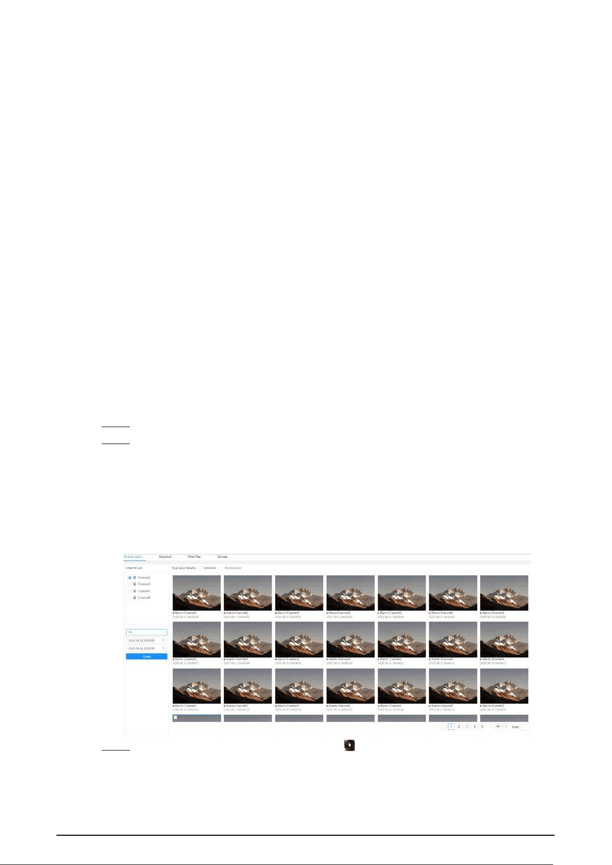
119
7 Picture
This chapter introduces the related functions and operations of image playback, including
configuring snapshot parameters, configuring snapshot plan and snapshot storage.
7.1 Playback
This section describes playing back and downloading images.
7.1.1 Playing Back Image
This section introduces the operation of image playback.
Prerequisites
●
This function is available on the camera with SD card.
●
Before playing back image, configure snapshot time range, snapshot storage method, snapshot
plan. For details, see"7.2 Setting Snapshot Parameters", "7.3 Setting Snapshot Plan" and "7.4
Storage".
Procedure
Step 1 Select
Record
>
Picture Query
.
Step 2 Select the channel, the snapshot type and snapshot time, and then click
Query
.
●
Click
All
, and select the snapshot type from the drop-down list, you can select from
All
,
General
,
Event
, and
Alarm
.
When selecting
Event
as the snapshot type, you can select the specific event types,
such as
Motion Detection
,
Video Tamper
and
Scene Changing
.
●
The dates with blue dots indicate there are snapshots on those days.
Figure 7-1 Image query
Step 3 Point to the searched image, and then click to play back the selected image.

120
Figure 7-2 Playback image
Table 7-1 Description of playback page
No Function Description
1 Snapshot list
Displays all searched snapshots. Click any files to play back
it.
Click
Back
at the upper-left corner to go to the
Picture
Query
page.
2 Manual display
●
Click to display the previous snapshot in the
snapshot list.
●
Click to display the next snapshot in the snapshot
list.
3 Slide show
Click to display the snapshots list one by one in
slide show mode.
4 Full screen
Click , and the snapshot is displayed in full-screen mode;
double-click the image or press Esc to exit full-screen
mode.
7.1.2 Downloading Image
Download images to a defined path. You can download a single image, or download images in
batches.
●
Operations might vary with different browsers.
●
For details of viewing or setting storage path, see "4.2 Local".
Step 1 Select
Picture
>
Picture Query
.
Step 2 Select the channel, the snapshot type, and snapshot time, and then click
Query
.
Step 3 Select the images to be downloaded.
●
Select at the upper-right corner of each image file to select one or multiple images.
The icon in the upper left corner of the selected file changes to .
●
Select next to
All
to select all searched images.

121
Figure 7-3 Selecting image file
Step 4 Click
Download
.
Step 5 Select the download format and storage path.
Figure 7-4 Downloading image
Step 6 Click
Start Download
.
The downloaded images are saved in the configured storage path. For details of storage
path, see "4.2 Local".
7.2 Setting Snapshot Parameters
Set the snapshot parameters, including type, size, quality and Interval.
Step 1 Select
Picture
>
Snapshot
.
Step 2 Select the channel, and then set the parameters.

122
Figure 7-5 Snapshot
Table 7-2 Description of snapshot parameters
Parameter Description
Type
You can select from
Scheduled
and
Event
.
●
Scheduled
: Capture images in the defined period. For details, see "7.3
Setting Snapshot Plan".
●
Event
: Capture images when configured event is triggered, such as
Motion Detection
,
Video Tamper
and
Scene Changing
.
Make sure that you have enabled the corresponding event detection
and the snapshot function.
Size
Set the size of the snapshot. It is the same with the resolution of the main
stream.
Quality Set the quality of the snapshot. The higher the value, the better the quality.
Interval Set the frequency of snapshot. You can select
Custom
to set the frequency.
Step 3 Click
Apply
.
7.3 Setting Snapshot Plan
Configure daily and holiday snapshot plan. After the corresponding alarm type (
General
,
Event
, and
Alarm
) is enabled, the snapshot channel links snapshot.
Background Information
Set certain days as holiday, and when the
Snapshot
is selected in the holiday schedule, the system
records video as the holiday schedule.
Procedure
Step 1 Click
Picture
on the main page, and then click the
Time Plan
tab.
Step 2 Select snapshot channel and then set snapshot plan.
●
Green represents normal snapshot plan (such as timing snapshot).
●
Yellow represents motion snapshot plan (such as snapshot triggered by intelligent
events).
●
Red represents alarm snapshot plan (such as snapshot triggered by alarm-in).
1) Select a snapshot type, and left-click and drag on the timeline to set the snapshot

123
period of each event.
Snapshot plan from top to bottom are respectively normal snapshot plan, motion
snapshot plan and alarm snapshot plan.
Figure 7-6 Configure through timeline
2) Click the selected time range and then set an accurate start and end time.
Figure 7-7 Configure accurate time period
●
Click
Copy
, and select the days that you want to copy to in the prompt page.
●
Select the
Select All
checkbox to select all day to copy the configuration.
●
You can set 6 time periods per day.
Step 3 Click
Apply
.
Step 4 Click
Holiday
to set holiday snapshot plan.

124
Figure 7-8 Holiday plan
●
Click to enable the holiday plan, and select the days that you need to set as
holiday.
The selected dates are shown in blue.
●
Click
Clear
to cancel the selection.
When holiday schedule setting is not the same as the general setting, holiday schedule
setting is prior to the general setting. For example, with holiday schedule enabled, if the
day is holiday, the system snapshots or records as holiday schedule setting; otherwise, the
system captures or records as general setting.
Step 5 Click
OK
.
7.4 Storage
This section introduces the configuration of the storage method for the snapshot.
Step 1 Select
Picture
>
Storage
.
Step 2 Select the storage method that you need for different types of snapshots.

125
Figure 7-9 Storage
Table 7-3 Description of storage parameters
Parameter Description
Event Type
Select from
General
,
Event
and
Alarm
.
Disk Full
Recording strategy when the disk is full.
●
Overwrite
: Cyclically overwrite the earliest video when the disk is
full.
●
Stop
: Stop recording when the disk is full.
Storage Method
Select from
Local storage
and
Network storage
●
Local storage
: Save the snapshots in the internal SD card.
Local storage
is displayed only on models that support SD card.
●
Network storage
: Save the snapshots in the FTP server or NAS.
Step 3 Click
Apply
.
7.4.1 Local Storage
Step 1 Select
Picture
>
Storage
.
Step 2 Select the snapshot strategy in
Disk Full
.
●
Overwrite
: Cyclically overwrite the earliest snapshot when the disk is full.
●
Stop
: Stop recording when the disk is full.
Step 3 Select
Local storage
in
Storage Method
to save the snapshots in the internal SD card.
Figure 7-10 Local storage
Step 4 Click
Apply
.
7.4.2 Network Storage
You can select from
FTP
and
NAS
.
When the network does not work, you can save all the files to the internal SD card for emergency.

126
7.4.2.1 FTP
Enable this function, and you can save all the files in the FTP server.
Step 1 Select
Picture
>
Storage
.
Step 2 Select the snapshot strategy in
Disk Full
.
●
Overwrite
: Cyclically overwrite the earliest snapshot when the disk is full.
●
Stop
: Stop snapshot when the disk is full.
Step 3 Select
Network storage
in
Storage Method
, and select
FTP
to save the snapshots in FTP
server.
You select
FTP
or
SFPT
from the drop-down list.
SFPT
is recommended.
Step 4 Click next to
Enable
to enable the FTP function.
Figure 7-11 FTP
Step 5 Configure FTP parameters.
Table 7-4 Description of FTP parameters
Parameter Description
Server IP The IP address of the FTP server.
Port The port number of the FTP server.
Username The username to log in to the FTP server.
Password The password to log in to the FTP server.
Storage Path The storage path in the FTP server.
Directory Structure
Select a directory level for the storage path and then set the
directory name for the level.
Urgently store to local
Click , and when the FTP server does not work, all the files are
saved to the internal SD card.

127
Step 6 Click
Apply
.
Step 7 Click
Test
to test whether FTP function works normally.
7.4.2.2 NAS
Enable this function, and you can save all the files in the NAS.
Step 1 Select
Picture
>
Storage
.
Step 2 Select the snapshot strategy in
Disk Full
.
●
Overwrite
: Cyclically overwrite the earliest snapshot when the disk is full.
●
Stop
: Stop snapshot when the disk is full.
Step 3 Select
Network storage
in
Storage Method
, and select
NAS
to save the snapshots in NAS
server.
Step 4 Select NAS protocol type.
●
NFS
(Network File System): A file system which enables computers in the same network
share files through TCP/IP.
●
SMB
(Server Message Block): Provides shared access for clients and servers.
Figure 7-12 NAS
Step 5 Select to enable NAS function, and then configure NAS parameters.
Table 7-5 Description of NAS parameters
Parameter Description
Server IP The IP address of the NAS server.
Storage Path The destination path in the NAS server.
Username
Username for logging in to the NAS server.
This is required when the protocol type is SMB.
Password
Password for logging in to the NAS server.
This is required when the protocol type is SMB.
Step 6 Click
Apply
.

128
8 AI
This chapter describes how to configure device AI events, including face recognition, IVS and video
metadata.
8.1 Configuring Smart Plan
Smart plans include face recognition, intelligence behavior analysis, video metadata and so on. The
smart functions of the camera cannot take effect until the smart plan has been enabled.
Step 1 Click
AI
>
AI Config
>
Smart Plan
.
Step 2 Enable the smart functions of the global and preset plan based on actual needs and then
click
Next
.
Before configuring the preset plan, please add the appropriate presets in advance. For
details of adding presets, see "4.5.1 Configuring Presets".
Step 3 Enable the intelligent functions of the
Global
and
Preset
as required, and then click
Next
.
Figure 8-1 Enable AI function
Step 4 Configure smart function rule as required. For details, see "8.2 Configuring Smart Function
Rule".
8.2 Configuring Smart Function Rule
8.2.1 Configuring Face Recognition
When a face is detected or recognized in the detection area, the system performs alarm linkage.
●
Face detection: When a face is detected in the area, the system performs alarm linkage, such as
recording and sending emails.
●
Face recognition: When a face is detected in the area, the system compares the captured face

129
image with the information in the face database, and links alarm according to the comparison
result.
Figure 8-2 Face recognition flowchart
8.2.1.1 Configuring Face Recognition Rule
When a face is detected or recognized in the detection area, the system performs alarm linkage.
Step 1 Click
AI
>
AI Config
>
Smart Plan
.
Step 2 Click
Rule Config
and then select
Face Recognition
.
Step 3 (Optional) Click the icon on the right of the screen to draw detection area, exclusion area
and filtering target model on the monitoring screen.
●
Click to draw a face detection area in the image, and right-click to finish the
drawing.
The default detection area is the whole screen.
●
Click to draw an exclusion area for face detection in the image, and right-click to
finish the drawing.
●
Click to draw the minimum size of the target, and click to draw the maximum
size of the target. Only when the target size is between the maximum size and the
minimum size, can the alarm be triggered.
●
Click , and then press and hold the left mouse button to draw a rectangle, the pixel
size is displayed.
●
Click to delete the detection line.
Step 4 Configure relevant parameter of face detection.

130
Figure 8-3 Configuring face recognition rule
Table 8-1 Description of face recognition parameters
Parameter Description
Face Enhancement
Select
Face Enhancement
to preferably guarantee clear faces with
low stream.
Target Box Overlay
You can add a bounding box to the face in the captured image to
highlight the face. The captured face image is saved in SD card or
the
Snapshot Path
. For the
Snapshot Path
see "4.2 Local".
Face Cutout
Set a range for the captured face image, including face and one-
inch image. It supports custom setting. When selecting
Custom
,
click on the right side, configure the parameters on the prompt
page, and then click
Apply
.
●
Customized width: Set snapshot width; enter the times of the
original face width. The value ranges from 1 to 5.
●
Customized face height: Set face height in snapshot; enter the
times of the original face height. The value ranges from 1 to 2.
●
Customized body height: Set body height in snapshot; enter
the times of the original body height. The value ranges from 0
to 4.
When the value is 0, it cuts out the face image only.
Snap Mode
●
Recognition Priority: The device takes snapshot immediately
when it detects faces.
●
Optimized Snapshot: The device captures the clearest images
within the optimized duration after it detects faces.
Optimized duration is configured in the
Advanced
below.
Property
Click
Property
to enable the properties display during face
recognition.
Advanced
Optimized Duration: Set a time period to capture the clearest image
after the camera detects face.
Step 5 Set arming periods and alarm linkage action.
●
Click
Add Schedule
to add time plan. For details, see "4.6.1.2.1 Adding Schedule".

131
●
Click
+ Event Linkage
to set the linkage action and configure linkage parameters. For
details, see "4.6.1.2 Alarm Linkage"
Step 6 Click
Apply
.
8.2.1.2 Configuring Face Database
By configuring face database, the face database information can be used to compare with the face
captured. The configuration process includes creating face database, adding face image, and face
modeling.
The operations for configuring face databases are all performed on
Face Database Config
.
8.2.1.2.1 Creating Face Database
Face database is the management center of face data information, including face image and face
data. It also provides comparison data for the captured face images.
Procedure
Step 1 Click
AI
>
AI Config
>
Smart Plan
.
Step 2 Click
Rule Config
and then select
Face Recognition
, and then
Step 3 Click
Face Database Config
to enter the face database configuration page.
Step 4 Click
Add
to configure the name of face database.
Figure 8-4 Adding face database
Step 5 Click
OK
.
The added face database information is displayed on the page.
Figure 8-5 Face database
Related Operations
●
Change the name of face database.
Click the text box under the name to change the name of face database.
●
Arm alarm.
Click to configure relevant parameters of face database control and alarm. For details,
see"8.2.1.3 Configuring Arming Alarm".
●
Managing face database.
Click to manage face database. You can set search conditions, register people, modify
people information and face modeling.
●
Deleting face database.

132
Click to delete face database.
8.2.1.2.2 Adding Face Images
Add face images to the created face database. You can add them one by one or in batches.
Requirements on face images:
●
A single image size is 50 KB–150 KB in JPEG format. The resolution is less than 1920 × 1080.
●
Face size is 30%–60% of the whole image. There must be at least 100 pixels between the ears.
●
Taken in full-face view directly facing the camera without makeup, filters, glasses, and fringe.
Eyebrow, mouth and other face features must be visible.
Single Adding
Add face images one by one. Select this way when you need to add a small number of face images.
Step 1 Click
AI
>
AI Config
>
Smart Plan
.
Step 2 Click
Rule Config
and then select
Face Recognition
.
Step 3 Click
Face Database Config
to enter the face database configuration page, and then click
next to the face database to be configured.
Step 4 Click
Register
.
Step 5 Click
Upload
to select the face image you want to upload, and then click
Open
.
After uploading the image, select a face area and click
OK
to save the face image. If there
are multiple faces in an image, select the target face and click
OK
to save the face image.
Figure 8-6 Add images
Step 6 Enter the information about face image according to the actual situation, and then click

133
Add to task list
.
Step 7 Click at the upper-right corner, and then click
Operation
.
●
If image adds successfully, it shows
Stored successfully. Modeling successful
.
●
If adding user fails, the error code is displayed on the page. View the fail reason
according to error code table. For details. see "Description of error code"
●
If image modeling fails, the error code is displayed on the page. Please modify the
image and remodel the image. For face modeling operation, see "8.2.1.2.4 Face
Modeling".
Table 8-2 Description of error code
Parameter Error Description
0x1134000C
Image importing
error
The image is too large, and the upper limit is 150 KB.
0x1134000E The number of the added images is to the upper limit.
0x11340019
The space of the face database exceeds the upper
limit.
1
Image modeling
error
The image format is not correct. Import the image in
JPG format.
2
No face in the image or the face is not clear. Change
the image.
3 Multiple faces in the image. Change the image.
4 Failed to decode the image. Change the image.
5
The image is not suitable to be imported to the face
database. Change the image.
6
Database operation error. Restart the camera and
model faces again.
7 Fails to get the image. Import the image again.
8
System error. Restart the camera and model faces
again.
Batch Adding
Import face images in batches when you need to add a large number of face images.
Prerequisites
Before importing images in batches, name face image in a format of "Name#SGender#BDate of
Birth#NRegion#PProvince#CCity#TCredentials Type#MID No.jpg" (for example, "John#S1#B1990-01-
01#NCN#PZhejiang#CHangzhou#T1#M000000199001010000).
●
The max size of a single face image is 150 KB, and the resolution is less than 1920p× 1080p.
●
When naming images,
Name
is required, and others are optional.
Table 8-3 Description of batch importing parameters
Parameters Description
Name Enter the corresponding name.
Gender "1" is male and "2" female.

134
Parameters Description
Date of Birth Format: yyyy-mm-dd, such as 2020-10-23.
Region
Enter the abbreviation name of the country or region, such as CN (for China),
BR (for Brazil).
Province
Enter the corresponding name of the province. Supports letters (capitalize
the initial letter), but do not support Chinese characters.
City Enter the corresponding name of the city.
Credential Type 1" is ID card, "2" is passport, “3” is Officer Card and“4” is others.
ID number Enter ID number.
Procedure
Step 1 Click
AI
>
AI Config
>
Smart Plan
.
Step 2 Click
Rule Config
and then select
Face Recognition
.
Step 3 Click
Face Database Config
to enter the face database configuration page
Step 4 Click next to the face database to be configured.
Step 5 Click
Batch Register
.
Step 6 Click
Select Picture
, and select storage path of the file.
Figure 8-7 Task list
Step 7 Click
Import
to import the face images.
After the importing is completed, the result will be displayed.
●
If the image is imported successfully, click
Next
to do modeling operation.
●
If the image importing failed, click
Query
to view the details of the images and error
code. For details, see "Description of error code".
Click
Export
to export the error details. Modify and reimport the face image according
to the error prompt.
Step 8 Click
Next
to do modeling operation.
The modeling result is displayed. If modeling failed, click
Query
and the failure details will
be displayed in the list. Point to the modeling status to view the details. Then you can
change image according to the failure reason. For modeling details, see "8.2.1.2.4 Face

135
Modeling".
8.2.1.2.3 Managing Face Images
Add face images to face database, and then manage and maintain face images to ensure the
information is correct.
Modifying Face Information
Step 1 Click
AI
>
AI Config
>
Smart Plan
.
Step 2 Click
Rule Config
and then select
Face Recognition
.
Step 3 Click
Face Database Config
to enter the face database configuration page.
Step 4 Click next to the face database to be configured.
Step 5 Click
Query
, set the criteria as needed, and then click
Search
.
Step 6 Select the row where the image or the personnel information is located, and then click .
Step 7 Edit face information according to the actual need. Click
Add to task list
.
Figure 8-8 Face information registration
Step 8 Click , and then click
Operation.
.
Deleting Face Data
Step 1 Click
AI
>
AI Config
>
Smart Plan
.
Step 2 Click
Rule Config
and then select
Face Recognition
.
Step 3 Click
Face Database Config
to enter the face database configuration page.
Step 4 Click next to the face database to be configured.
Step 5 Click
Query
, and then set the search criteria. Click
Search
, and then select the face
information that needs to be deleted and delete it.

136
●
Single delete: Select the row where the face image or the personnel information is
located, and click to delete the face image.
●
Delete in batches: Select at the upper-right corner of the face image or of the
row where the personnel information is located.. Select the information, click
Delete
,
then click .Click
Operation
to delete the selected face images.
●
Delete all: When viewing face images in a list, click of the row where the serial
number is located; when viewing by thumbnail, select
All
to select all face images. Click
Delete
, then click , and then click
Operation
to delete all face images.
8.2.1.2.4 Face Modeling
Extract and import the relevant information of face images through face modeling, and create a face
feature model for smart detection such as face recognition.
●
The more face images you select, the longer the face modeling process will take.
●
During the modeling process, some smart detection functions (such as face comparison) are
temporarily unavailable and can be resumed after the modeling is completed.
Step 1 Click
AI
>
AI Config
>
Smart Plan
.
Step 2 Click
Rule Config
and then select
Face Recognition
.
Step 3 Click
Face Database Config
to enter the face database configuration page.
Step 4 Click next to the face database to be configured.
Step 5 Start modeling.
●
Modeling some images: Select the face images to be modeled, and then click
Modeling
.
If there are many face images in the face database, you can set search criteria to select
the images that need to be modeled.
●
Modeling all images: Click
Modeling All
, and the face images in invalid state in the face
database are modeled
Step 6 View the modeling result.
When the modeling failed, click
Query
to view the details.
Figure 8-9 Modeling result
Click to view the face image in list format; click to view the face image in
thumbnail format.
●
When the modeling status is
Valid
in the list or is displayed at the lower-left corner of
the thumbnail, it means the modeling is successful.
●
When the modeling status is
Invalid
in the list or is displayed at the lower-left corner of

137
the thumbnail, it means the modeling failed. Point to the modeling status in the list to
view the details of the failure. Change the images according to the reasons.
Figure 8-10 Modeling status (list)
8.2.1.3 Configuring Arming Alarm
When face recognition succeeded or failed, the device outputs alarms.
Step 1 Click
AI
>
AI Config
>
Smart Plan
.
Step 2 Click
Rule Config
and then select
Face Recognition
.
Step 3 Click
Face Database Config
to enter the face database configuration page.
Step 4 Click next to the face database to be configured.
Step 5 Arm face database.
1) Click to enable arm function.
The snapshot will be compared to the images in the armed face database.
2) Set similarity.
The detected face will only match the face features in the face database when the
defined similarity is reached. After successful match, the comparison result is displayed
on the
Live
page.
Figure 8-11 Arm alarm
Step 6 Select
Alarm Mode
.
●
All
: The camera outputs alarms whether the detected face matches the face picture in
the database or not.
●
General:
The camera outputs alarms when the detected face matches that in the face
database.
●
Stranger
: The camera outputs alarms when the detected face fails to match that in the

138
face database.
●
Select none
: The camera does not output alarms whether the detected face matches
the face picture in the database or not.
Step 7 Set arming periods and alarm linkage action.
●
Click
Add Schedule
to add time plan. For details, see "4.6.1.2.1 Adding Schedule".
●
Set the linkage action and configure linkage parameters. For details, see "4.6.1.2 Alarm
Linkage"
Step 8 Click
Apply
.
8.2.1.4 Viewing Face Recognition Result
On the
Live
page, select
Face Mode
from the display mode drop-down list on the upper-right
corner to view the
Live
page of face recognition.
●
The live image is displayed at the left side, and the captured face images and attribute
information are displayed at the right side. When the recognition is successful, the captured face
images, images in the database and the similarity of the face images and images in the database
are displayed at the right side; the snapshot count and thumbnails are displayed at the bottom of
the live image.
●
Click to set the attributes. For details, see "Configuring Display Properties".
Figure 8-12 Face recognition result
8.2.2 Configuring IVS
This section introduces scene selection requirements, rule configuration, and global configuration
for IVS (intelligent video surveillance).
Here are the basic requirements on the scene.
●
The target should occupy no more than 10% of the whole image.
●
The target size in the image should be no more than 10 × 10 pixels. The size of abandoned object
in the image should be no less than 15 × 15 pixels (CIF image). The target height and width
should no more than a third of the image height and width. The recommended target height is
10% of the image height.
●
The brightness difference of the target and the background should be no less than 10 gray levels.
●
The target should be continuously present in the image for no less than 2 seconds, and the

139
moving distance should be larger its width and no less than 15 pixels (CIF image) at the same
time.
●
Reduce the complexity of surveillance scene as much as you can. Intelligent analysis functions
are not recommended to be used in scene with dense targets and frequent illumination change.
●
Avoid areas such as glass, reflective ground, water surface, and areas interfered by branch,
shadow and mosquito. Avoid backlight scene and direct light.
8.2.2.1 Global Configuration
Set global rules for IVS, including calibration drawing, calibration verification and sensitivity.
Background Information
Determine corresponding relationship between 2D image captured by the camera and 3D actual
object according to one horizontal ruler and three vertical rulers calibrated by the user and the
corresponding actual distance. Here are the applicable scenes.
●
Medium or distant view with installation height of more than three meters. Scenes with parallel
view or ceiling-mounted are not supported.
●
Calibrate horizontal plane, not vertical walls or sloping surfaces.
●
This function is not applicable to scenes with distorted view, such as the distorted views captured
by super wide-angle camera.
Pay attention to the following points.
●
Calibration Drawing
◇
Calibration area: The calibration area drawn should be on one horizontal plane.
◇
Vertical ruler: The bottom of three vertical rulers should be on the same horizontal plane.
Select three reference objects with fixed height in triangular distribution as vertical rulers,
such as vehicle parked at roadside or road lamp poles. Arrange three persons to draw at each
of the three positions in the monitoring scene.
◇
Horizontal ruler: Select reference object with known length on the ground, such as sign on
the road, or use a tape to measure the actual length.
●
Calibration Verification
After setting the ruler, draw a straight line on the image, check the estimated value of the straight
line, and then compare this value with the value measured in the actual scene to verify
calibration accuracy. In case of major difference between the estimated value and the actual one,
fine-tune or reset parameters until the error requirement is met.
Procedure
Step 1 Click
AI
>
AI Config
>
Smart Plan
.
Step 2 Click
Rule Config
, and then select
IVS
.
Step 3 Click
Global Config
.
Step 4 Configure calibration area and rulers on the left screen.
1) Click and draw a calibration area in the image, and right-click to finish the drawing.
2) Click the ruler icon to draw one horizontal ruler and three vertical rulers in the
calibration area.
●
indicates vertical ruler, and indicates horizontal ruler.
●
Select an added ruler, and click to delete the ruler.
3) Configure the actual length.
Step 5 Configure parameters for the IVS of global configuration.

140
Sensitivity: Adjust the filter sensitivity. With higher value, it is easier to trigger an alarm
when low-contrast object and small object are captured, and the false detection rate is
higher.
Figure 8-13 Global configuration (IVS)
Step 6 Click
Apply
.
Related Operations
1. Select the verification type, and then click
Calibration Verification
.
To verify vertical ruler and horizontal ruler, respectively select
Height Verification
and
Width
Verification
.
2. Draw a straight line in the image to verify whether the rulers are correctly set.
In case of major difference between the estimated value and the actual one, fine-tune or reset
parameters until the error requirement is met.
8.2.2.2 Rule Configuration
This section introduces the rules used on IVS, including tripwire, intrusion, abandoned object,
missing object, fast moving, parking detection, crowd gathering, crossing virtual fence and loitering
detection.
Prerequisites
The global configuration for IVS has been completed.
Background Information
The roles and applicable scenes of various rules are as follows. The following section uses tripwire as
an example to introduce the rule configuration of IVS.
Table 8-4 Description of IVS functions
Rule Functions Applicable Scene
crossing
virtual fence
When a target crosses the fence
toward the defined direction, the
alarm is triggered and the linkage is
executed.
Scenes such as roads, airports and
other isolation zones.
Tripwire
When a target crosses the line toward
the defined direction, the alarm is
triggered and the linkage is executed.
Scenes with sparse targets and no
occlusion among targets, such as the
perimeter protection of unattended

141
Rule Functions Applicable Scene
Intrusion
When the target enters, leaves, or
appears in the detection area, an alarm
is triggered, and the system performs
defined alarm linkages.
area.
Abandoned
object
When an object is abandoned in the
detection area over the defined time,
an alarm is triggered, and then the
system performs defined alarm
linkages.
Scenes with sparse targets and
without obvious and frequent light
change. Simple scene in the detection
area is recommended.
●
Missed alarm might increase in
the scenes with dense targets,
frequent occlusion, and people
staying.
●
In scenes with complex
foreground and background, false
alarm might be triggered for
abandoned or missing object.
Missing
object
When an object is taken out of the
detection area over the defined time,
an alarm is triggered, and then the
system performs defined alarm
linkages.
Fast moving
When the motion speed is higher than
the defined speed, an alarm is
triggered, and then the system
performs defined alarm linkages.
Scenes with sparse targets and less
occlusion. The camera should be
installed right above the monitoring
area. The light direction should be
vertical to the motion direction.
Parking
detection
When the target stays over the defined
time, an alarm is triggered, and then
the system performs defined alarm
linkages.
Road monitoring and traffic
management.
Crowd
gathering
When the crowd gathers or the crowd
density is large, an alarm is triggered,
and then the system performs defined
alarm linkages.
Scenes with medium or long distance,
such as outdoor plaza, government
entrance, station entrance and exit. It
is not suitable for short-distance view
analysis.
Loitering
detection
When the target loiters over the
shortest alarm time, an alarm is
triggered, and then the system
performs defined alarm linkages. After
alarm is triggered, if the target stays in
the area within the time interval of
alarm, then alarm will be triggered
again.
Scenes such as park and hall.
Procedure
Step 1 Click
AI
>
AI Config
>
Smart Plan
.
Step 2 Click
Rule Config
and then select
IVS
.
Step 3 Click
Rule Config
.
Step 4 Click
Add Rule
on the
Rule Config
page, and then select
Tripwire
from the drop-down
list.
The added rules are displayed in the drop-down list. Click the name, and you can edit the
rule name; the rule is enabled by default.

142
Figure 8-14 Tripwire
Step 5 Click to draw rule lines in the image. Right-click to finish drawing.
Different rules have slightly different drawing requirements. After drawing rules, drag
corners of the detection area to adjust the area range.
Figure 8-15 Drawing rule
Table 8-5 Description of IVS analysis drawing rules
Rule Description
Crossing virtual
fence
Draw a detection line.
Tripwire
Intrusion Draw a detection area.
●
During the detection of abandoned objects, the alarm is also triggered
if pedestrian or vehicle stays for a long time. If the abandoned object is
smaller than pedestrian and vehicle, set the target size to filter
pedestrian and vehicle or properly extend duration to avoid false alarm
triggered by transient staying of pedestrian.
●
During the detection of crowd gathering, false alarm might be
triggered by low installation height, large percentage of single person
in an image or obvious target occlusion, continuous shaking of the
camera, shaking of leaves and tree shade, frequent opening or closing
of retractable door, or dense traffic or people flow.
Abandoned object
Missing object
Fast moving
Parking detection
Crowd gathering
Loitering detection

143
Table 8-6 Description of IVS analysis drawing rules
Rule Description
Crossing virtual
fence
Draw a detection line.
Tripwire
Intrusion Draw a detection area.
●
During the detection of abandoned objects, the alarm is also triggered
if pedestrian or vehicle stays for a long time. If the abandoned object is
smaller than pedestrian and vehicle, set the target size to filter
pedestrian and vehicle or properly extend duration to avoid false alarm
triggered by transient staying of pedestrian.
●
During the detection of crowd gathering, false alarm might be
triggered by low installation height, large percentage of single person
in an image or obvious target occlusion, continuous shaking of the
camera, shaking of leaves and tree shade, frequent opening or closing
of retractable door, or dense traffic or people flow.
Abandoned object
Missing object
Fast moving
Parking detection
Crowd gathering
Loitering detection
Step 6 (Optional) Click other icons at the right side of the image to filter targets in the image.
●
Click to draw the minimum size of the detection target and click to draw the
maximum size of the detection target. Only when the target size is between the
maximum size and the minimum size, can the alarm be triggered.
●
When the rule of crowd gathering is configured, you need to draw the minimum
gathering area. Click to draw the minimum gathering area in the scene. The alarm
is triggered when the number of people in the detection area exceeds the minimum
and the time exceeds the duration.
●
Click , and then press and hold the left mouse button to draw a rectangle, the pixel
size is displayed.
●
Click to delete the detection line.
Step 7 Set rule parameters for IVS.

144
Figure 8-16 IVS parameters
Table 8-7 Description of IVS parameters
Parameter Description
Direction
Set the direction of rule detection.
●
When setting tripwire, select
A->B
,
B->
A, or
A<->B
.
●
When setting intrusion, select
Enter
,
Exit
, or
Both
.
Target Filter
After enabling
Target filter
, effective targets are not detected and alarms
will not be triggered. This function is currently supported by tripwire,
intrusion and fast moving.
Effective targets include
Human
and
Motor Vehicle
. Among them,
non-
motor vehicle
belongs to the category of
People
.
Effective Target
Action When setting intrusion action, select
Appear
or
Cross
.
Duration
●
For abandoned object, the duration is the shortest time for triggering an
alarm after an object is abandoned.
●
For missing object, the duration is the shortest time for triggering an
alarm after an object is missing.
●
For parking detection, crowd gathering, or loitering detection, the
duration is the shortest time for triggering an alarm after an object
appears in the area.

145
Parameter Description
Sensitivity
●
For fast moving, sensitivity is related to the triggering speed. Lower
sensitivity requires faster moving speed to trigger the alarm.
●
For crowd gathering, sensitivity is related to the alarm triggering time. It
is easier to trigger the alarm with higher sensitivity.
Step 8 Set arming periods and alarm linkage action.
●
Click
Add Schedule
to add time plan. For details, see "4.6.1.2.1 Adding Schedule".
●
Click
+ Event Linkage
to set the linkage action and configure linkage parameters. For
details, see "4.6.1.2 Alarm Linkage".
Step 9 Click
Apply
.
If you need to click on the upper-right corner of the page to view alarm information,
you need to subscribe relevant alarm event. For details, see "4.6.1.4.2 Subscribing to Alarm
Information".
8.2.3 Configuring Video Metadata
Classify people, non-motor vehicles and motor vehicles in the captured video, and display the
relevant attributes on the
Live
page.
8.2.3.1 Global Configuration
Configure global rules for video metadata, including global parameters for faces and scenes.
Step 1 Select
AI
>
AI Config
>
Smart Plan
.
Step 2 Click
Rule Config
, and then select
Video Metadata
.
Step 3 Click
Global Config
.
Step 4 Configure global configuration parameters.
Figure 8-17 Global configuration

146
Table 8-8 Description of global configuration parameter
Parameter Description
Target Box Overlay
Overlay target box on the captured images to mark the target
position.
Four types of target boxes are supported. Select the target box as
needed.
The captured images are stored in SD card or the configured
storage path. For details, see "4.2 Local".
Face Enhancement
Enable
Face Enhancement
to preferably guarantee clear face with
low stream.
Face Cutout
Set a range for matting face image, including face image and one-
inch image.
Picture mode
●
Default: Apply default image parameters to capture images.
●
Number Plate Priority: Apply the image parameters
corresponding to the number plate to capture the image.
●
Face Priority: Apply the image parameters corresponding to the
face to capture the image.
Step 5 Click
Apply
.
8.2.3.2 Rule Configuration
Configure detection scenes and rules, including the rule configuration of people, non-motor vehicles
and motor vehicle.
Prerequisites
Global configuration for video metadata has been completed.
Procedure
Step 1 Select
AI
>
AI Config
>
Smart Plan
.
Step 2 Click
Rule Config
, and then select
Video Metadata
.
Step 3 Click
Rule Config
.
Step 4 Click
Add Rule
and then select rule type from the drop-down list.
The added rules are displayed in the drop-down list. Click the text box under
Name
to edit
the rule name. The rule is enabled by default.
Figure 8-18 Rule configuration (video metadata)
Step 5 Configure image information.
1) Click the after the corresponding rule.
2) Configure overlay information and adjust its position.
This section uses the configuration of non-motor vehicle as an example.

147
Figure 8-19 Configure image parameters (non-motor vehicle)
3) Click
Apply
.
Step 6 (Optional) Click the icon on the right of the screen to draw detection area, exclusion area
and filtering target model on the monitoring screen.
●
After enabling the rule, the detection area is displayed in the monitoring screen. Click
, and then drag any corner of the box to adjust the size of the area
●
Click to draw an area exclusion area for face detection in the image, and right-click
to finish the drawing.
●
Click to draw the minimum size of the detection target and click to draw the
maximum size of the detection target. Only when the target size is between the
maximum size and the minimum size, can the alarm be triggered.
●
Click to delete the drawn filtering rule detection line or area.
Step 7 Configure the rule parameters of video metadata.

148
Figure 8-20 Configuring rule parameters (traffic flow statistics)
Table 8-9 Description of video metadata parameter
Parameter Description
People Flow
Statistics
Click next to
People Flow Statistics
to count the number of people in
the detection area.
Traffic Flow
Statistics (Non-
motor Vehicles)
Click next to
Traffic Flow Statistics (Non-motor Vehicles)
to count
the number of non-motor vehicles in the detection area.
Traffic Flow
Statistics
Click next to
Traffic Flow Statistics
to count the number of motor
vehicles in the detection area.
Snapshot Mode
●
Optimized: Capture the images until the vehicle disappears from the
image, and upload the clearest image.
●
Tripwire: Capture the images when the vehicle triggers tripwire as the
configured direction. The steps are as follows:
1. Select
Tripwire
.
2. Select the direction from
A to B
,
B to A
and
Both.
3. Adjust the position of rule line as needed.
Step 8 Set arming periods and alarm linkage action.
●
Click
Add Schedule
to add time plan. For details, see "4.6.1.2.1 Adding Schedule".
●
Click
+ Event Linkage
to set the linkage action and configure linkage parameters. For
details, see "4.6.1.2 Alarm Linkage"
Step 9 Click
Apply
.
8.2.3.3 Viewing Video Metadata Report
Select
Metadata Mode
on the upper-left corner of the
Live
page to view the live video image of

149
video metadata.
●
The left side displays real-time live screen; the right side displays large view of the snapshot and
detailed attribute information; the bottom displays the face, human body, non-motor vehicle and
motor vehicle snapshot statistics and snapshot thumbnails.
●
Click to change the attributes shown in the image. For details, see "Configuring Display
Properties".
Figure 8-21 Video metadata report
8.3 Configuring Tour Plan
You can configure the tour mode and time plan for different periods.
Step 1 Select
AI
>
Tour Plan
.
Step 2 Select
Enable
to enable tour plan function.
Step 3 Select tour mode and idle interval.
●
Tour mode Select
: It only supports
Scene Priority
at present. The Camera tours
according to the set duration of the scene.
●
Idle Interval
: The time between the user manually operate the Camera and the Camera
automatically rotates to the smart plan scene.
Step 4 Configure tour plan.
1) Set the start time and end time of the tour.
2) Select period, and then click
Setting
to configure multi-scenario tour.

150
Figure 8-22 Multi-scenario tour
Table 8-10 Description of multi-scenario tour parameter
Parameter Description
Stay Time
Set the time that the Camera stays in the
scene. Double-click the stay time to modify the
time.
Priority Sorting
Set the priority of multiple scenes. Click or
to adjust the order.
Delete Click to delete the scene.
Add Scenario Click
Add Scenario
to add a new tour scene.
3) Click
OK
to complete the configuration of multi-scenario tour.
Step 5 (Optional) Click
Copy
to copy the configuration to the selected date.
Step 6 Click
OK
.

151
9 Security
9.1 Security Status
Background Information
Detect the user and service, and scan the security modules to check the security status of the
Camera, so that when abnormality appears, you can process it timely.
●
User and service detection: Detect login authentication, user status, and configuration security to
check whether the current configuration meet requirement.
●
Security modules scanning: Scan the running status of security modules, such as audio/video
transmission, trusted protection, securing warning and attack defense, but not detect whether
they are enabled.
Procedure
Step 1 Select
Security
>
Security Status
.
Step 2 Click
Rescan
to scan the security status of the Camera.
During the scanning, the icon is grey. When the icon turns blue, the scanning is complete.
Figure 9-1 Security status
Related Operations
After scanning, different results will be displayed in different color. Yellow indicates that the security
modules are abnormal, and green indicates that the security modules are normal.
1. Click
Details
to view the details of the scanning result.
2. Click
Ignore
to ignore the exception, and it will not be scanned in next scanning.
3. Click
Optimize
, and the corresponding page is displayed. You can edit the configuration to clear
the exception.

152
Figure 9-2 Security status
9.2 System Service
Service functions can be used only after system services are enabled.
9.2.1 802.1x
Cameras can connect to LAN after passing 802.1x authentication.
Step 1 Select
Security
>
System Service
>
802.1x
.
Step 2 Select the NIC name as needed, and click to enable it.
Step 3 Select the authentication mode, and then configure parameters.
●
PEAP (Protected EAP protocol).
1. Select PEAP as the authentication mode.
2. Enter the username and password that has been authenticated on the server.
3. (Optional) Click next to CA certificate, and select the trusted CA certificate in
list.
If there is no certificate in the list, click
Certificate Management
at the left
navigation bar. For details, see "9.4.2 Installing Trusted CA Certificate".
Figure 9-3 802.1x (PEAP)
●
TLS (Transport Layer Security). It is applied in two communication application programs
to guarantee the security and integrity of the data.
1. Select TLS as the authentication mode.
2. Enter the username.

153
3. Select the certificate from the certificate list on the
Device Certificate
page.
If there is no certificate in the list, click
Certificate Management
at the left
navigation bar. For details, see "9.4.1 Installing Device Certificate".
4. (Optional) Click next to CA certificate, and select the trusted CA certificate in
list.
If there is no certificate in the list, click
Certificate Management
at the left
navigation bar. For details, see "9.4.2 Installing Trusted CA Certificate".
Figure 9-4 802.1x (TLS)
Step 4 Click
Apply
.
9.2.2 HTTPS
Create a certificate or upload an authenticated certificate, and then you can log in through HTTPS
with your PC. The HTTPS can protect page authenticity on all types of websites, secure accounts, and
keep user communications, identity, and web browsing private.
●
We recommend enabling the HTTPS. Otherwise, the device data may be leaked.
●
After HTTPS is enabled, TLSv1.1 and earlier versions are supported by default. However, earlier
version of TLS might have security risks. Please select carefully.
Procedure
Step 1 Select
Security
>
System Service
>
HTTPS
.
Step 2 Click to enable HTTPS.
Step 3 Select the certificate.
If there is no certificate in the list, click
Certificate Management
at the left navigation bar.
For details, see "9.4.1 Installing Device Certificate".

154
Figure 9-5 HTTPS
Step 4 Click
Apply
.
Related Operations
Enter https://IPaddress in the browser.
●
If you have already installed the certificate, the normal login page will be displayed.
●
If you have not installed the certificate, the browser displays a certificate error message.
9.3 Attack Defense
9.3.1 Firewall
Configure firewall to limit access to the camera.
Step 1 Select
Security
>
Attack Defense
>
Firewall
.
Step 2 Click to enable the firewall function.
Figure 9-6 Firewall
Step 3 Select
Allowlist
or
Blocklist
as the mode.
●
Allowlist
: Only when the IP/MAC address of your PC is in the allowlist, can you access
the camera. Ports are the same.
●
Blocklist
: When the IP/MAC address of your PC is in the blocklist, you cannot access the
camera. Ports are the same.
Step 4 Click
Add
to add the host IP/MAC address to
Allowlist
or
Blocklist
, and then click
OK
.

155
Figure 9-7 Firewall
Step 5 Click
Apply
.
Related Operations
●
Click to edit the host information.
●
Click to delete the host information.
9.3.2 Account Lockout
If you consecutively enter a wrong password more than the configured value, the account will be
locked.
Step 1 Select
Security
>
Attack Defense
>
Account Lockout
.
Step 2 Configure the login attempt and lock time for device account and ONVIF user.
●
Login attempt: Upper limit of login attempts. If you consecutively enter a wrong
password more than the defined value, the account will be locked.
●
Lock time: The period during which you cannot log in after the login attempts reaches
upper limit.
Figure 9-8 Account lockout
Step 3 Click
Apply
.

156
9.3.3 Anti-DoS Attack
You can enable
SYN Flood Attack Defense
and
ICMP Flood Attack Defense
to defend the device
against DoS (Denial of Service) attack.
Step 1 Select
Security
>
Attack Defense
>
Anti-DoS Attack
.
Step 2 Select
SYN Flood Attack Defense
or
ICMP Flood Attack Defense
to defend the device
against Dos attack.
Figure 9-9 Anti-DoS attack
9.4 CA Certificate
9.4.1 Installing Device Certificate
Create a certificate or upload an authenticated certificate, for example when you log in through
HTTPS with your PC, you need to verify device certificate.
9.4.1.1 Creating Certificate
Creating certificate in the device.
Procedure
Step 1 Select
Security
>
CA Certificate
>
Device Certificate
.
Step 2 Select
Install Device Certificate
.
Step 3 Select
Create Certificate
, and click
Next
.
Step 4 Enter the certificate information.
IP or domain name of the device is automatically entered in
IP/Domain Name
.

157
Figure 9-10 Certificate information (1)
Step 5 Click
Create and install certificate
.
After the certificate is created successfully, you can view the created certificate on the
Device Certificate
page.
Related Operations
●
Click
Enter Edit Mode
, you can edit the custom name of the certificate.
●
Click to download the certificate.
●
Click to delete the certificate.
9.4.1.2 Applying for and Importing CA Certificate
Import the third-party CA certificate to the camera.
Procedure
Step 1 Select
Security
>
CA Certificate
>
Device Certificate
.
Step 2 Select
Installing Device Certificate
.
Step 3 Click
Apply for CA Certificate and Import (Recommended)
, and then click
Next
.
Step 4 Enter the certificate information.
IP or domain name of the device is automatically entered in
IP/Domain Name
.

158
Figure 9-11 Certificate information (2)
Step 5 Click
Create and Download
.
Save the request file to your PC.
Step 6 Apply for the CA certificate from the third-party certificate authority.
Step 7 Import the signed CA certificate.
1) Save the CA certificate to the PC.
2) Select
Install Device Certificate
, click
Apply for CA Certificate and Import
(Recommended)
, and then click
Next
.
3) Click
Browse
to select the signed CA certificate.
4) Click
Install and Import
.
After the certificate is created successfully, you can view the created certificate on the
Device Certificate
page.
●
Click
Recreate
to create the request file again.
●
Click
Import Later
to import the certificate next time.
Related Operations
●
Click
Enter Edit Mode
, you can edit the custom name of the certificate.
●
Click to download the certificate.
●
Click to delete the certificate.
9.4.1.3 Installing Existing Certificate
Import the existing third-party certificate to the Camera. When apply for the third-party certificate,
you also need to apply for the private key file and private key password.
Step 1 Select
Security
>
CA Certificate
>
Device Certificate
.
Step 2 Select
Install Device Certificate
.
Step 3 Select
Install Existing Certificate
, and click
Next
.
Step 4 Click
Browse
to select the certificate and private key file, and enter the private key

159
password.
Figure 9-12 Certificate and private key
Step 5 Click
Import and Install
.
After the certificate is created successfully, you can view the created certificate on the
Device Certificate
page.
Related Operations
●
Click
Enter Edit Mode
, you can edit the custom name of the certificate.
●
Click to download the certificate.
●
Click to delete the certificate.
9.4.2 Installing Trusted CA Certificate
CA certificate is a digital certificate for the legal identity of the camera. For example, when the
camera accesses the LAN through 802.1x, the CA certificate is required.
Step 1 Select
Security
>
CA Certificate
>
Trusted CA Certificates
.
Step 2 Select
Install Trusted Certificate
.
Step 3 Click
Browse
to select the certificate.
Figure 9-13 Installing trusted certificate
Step 4 Click
OK
.
After the certificate is created successfully, you can view the created certificate on the
Trusted CA Certificate
page.

160
Related Operations
●
Click
Enter Edit Mode
, you can edit the custom name of the certificate.
●
Click to download the certificate.
●
Click to delete the certificate.
9.5 A/V Encryption
The device supports audio and video encryption during data transmission.
We recommend you to enable A/V Encryption function. There might be safety risk if this function is
disabled.
Step 1 Select
Security
>
A/V Encryption
.
Step 2 Configure the parameters.
Figure 9-14 A/V encryption
Table 9-1 A/V encryption parameter
Area Parameter Description
Private Protocol
Enable
Enables stream frame encryption by
using private protocol.
There might be safety risk if this
service is disabled.
Encryption Type Use the default setting.
Update Period of Secret Key
Secret key update period.
Value range: 0–720 hours. 0 means
never update the secret key.
Default value: 12.
RTSP over TLS Enable
Enables RTSP stream encryption by
using TLS.
There might be safety risk if this
service is disabled.

161
Area Parameter Description
Select a device certificate
Select a device certificate for RTSP
over TLS.
Certificate Management
For details about certificate
management, see "9.4.1 Installing
Device Certificate".
Step 3 Click
Apply
.
9.6 Security Warning
When security exception event is detected, the camera sends a warning to remind you to process it
timely, to avoid security risk.
Step 1 Select
Security
>
Security Warning
.
Step 2 Click to enable security warning.
Step 3 Configure the parameters.
Figure 9-15 Security warning
Step 4 Set arming periods and alarm linkage action. For details, see "4.6.1.2 Alarm Linkage".
Click
+ Event Linkage
to set the linkage action.
Step 5 Click
Apply
.

162
10 Report
View the statistics result of video metadata in report form.
Procedure
Step 1 Click
Report
>
Report
>
Video Metadata
.
Step 2 Set the period for the report.
For multi-channel camera, select the channel first.
Step 3 Click
Search
.
Figure 1-1 Video metadata report
Related Operations
●
Select the report form.
◇
Click to display the report in line chart.
◇
Click to display the report in bar chart.
●
Select the statistics type on the upper-right corner.
The statistics result of unselected types will not be displayed.
●
Export reports.
Select the file format, and then click
Export
.
◇
Select
png
: Displays the report in image format.
◇
Select
csv
: Displays the report in list format.

163
Appendix 1 Cybersecurity Recommendations
Cybersecurity is more than just a buzzword: it’s something that pertains to every device that is
connected to the internet. IP video surveillance is not immune to cyber risks, but taking basic steps
toward protecting and strengthening networks and networked appliances will make them less
susceptible to attacks. Below are some tips and recommendations from Dahua on how to create a
more secured security system.
Mandatory actions to be taken for basic device network security:
1. Use Strong Passwords
Please refer to the following suggestions to set passwords.
The length should not be less than 8 characters.
Include at least two types of characters; character types include upper and lower case
letters, numbers and symbols.
Do not contain the account name or the account name in reverse order.
Do not use continuous characters, such as 123, abc, etc.
Do not use overlapped characters, such as 111, aaa, etc.
2. Update Firmware and Client Software in Time
According to the standard procedure in Tech-industry, we recommend to keep your device
(such as NVR, DVR, IP camera, etc.) firmware up-to-date to ensure the system is equipped
with the latest security patches and fixes. When the device is connected to the public
network, it is recommended to enable the “auto-check for updates” function to obtain
timely information of firmware updates released by the manufacturer.
We suggest that you download and use the latest version of client software.
"Nice to have" recommendations to improve your device network security:
1. Physical Protection
We suggest that you perform physical protection to device, especially storage devices. For
example, place the device in a special computer room and cabinet, and implement well-done
access control permission and key management to prevent unauthorized personnel from
carrying out physical contacts such as damaging hardware, unauthorized connection of
removable device (such as USB flash disk, serial port), etc.
2. Change Passwords Regularly
We suggest that you change passwords regularly to reduce the risk of being guessed or cracked.
3. Set and Update Passwords Reset Information Timely
The device supports password reset function. Please set up related information for password
reset in time, including the end user’s mailbox and password protection questions. If the
information changes, please modify it in time. When setting password protection questions, it is
suggested not to use those that can be easily guessed.
4. Enable Account Lock
The account lock feature is enabled by default, and we recommend you to keep it on to guarantee
the account security. If an attacker attempts to log in with the wrong password several times, the
corresponding account and the source IP address will be locked.
5. Change Default HTTP and Other Service Ports
We suggest you to change default HTTP and other service ports into any set of numbers between
1024–65535, reducing the risk of outsiders being able to guess which ports you are using.
6. Enable HTTPS
We suggest you to enable HTTPS, so that you visit Web service through a secure communication
channel.
7. MAC Address Binding
We recommend you to bind the IP and MAC address of the gateway to the device, thus reducing
the risk of ARP spoofing.
8. Assign Accounts and Privileges Reasonably
According to business and management requirements, reasonably add users and assign a
minimum set of permissions to them.
9. Disable Unnecessary Services and Choose Secure Modes

164
If not needed, it is recommended to turn off some services such as SNMP, SMTP, UPnP, etc., to
reduce risks.
If necessary, it is highly recommended that you use safe modes, including but not limited to the
following services:
SNMP: Choose SNMP v3, and set up strong encryption passwords and authentication
passwords.
SMTP: Choose TLS to access mailbox server.
FTP: Choose SFTP, and set up strong passwords.
AP hotspot: Choose WPA2-PSK encryption mode, and set up strong passwords.
10. Audio and Video Encrypted Transmission
If your audio and video data contents are very important or sensitive, we recommend that you
use encrypted transmission function, to reduce the risk of audio and video data being stolen
during transmission.
Reminder: encrypted transmission will cause some loss in transmission efficiency.
11. Secure Auditing
Check online users: we suggest that you check online users regularly to see if the device is
logged in without authorization.
Check device log: By viewing the logs, you can know the IP addresses that were used to log
in to your devices and their key operations.
12. Network Log
Due to the limited storage capacity of the device, the stored log is limited. If you need to save the
log for a long time, it is recommended that you enable the network log function to ensure that
the critical logs are synchronized to the network log server for tracing.
13. Construct a Safe Network Environment
In order to better ensure the safety of device and reduce potential cyber risks, we recommend:
Disable the port mapping function of the router to avoid direct access to the intranet devices
from external network.
The network should be partitioned and isolated according to the actual network needs. If
there are no communication requirements between two sub networks, it is suggested to use
VLAN, network GAP and other technologies to partition the network, so as to achieve the
network isolation effect.
Establish the 802.1x access authentication system to reduce the risk of unauthorized access
to private networks.
Enable IP/MAC address filtering function to limit the range of hosts allowed to access the
device.
More information
Please visit Dahua official website security emergency response center for security announcements
and the latest security recommendations.

165